Embed Size (px)
Citation preview
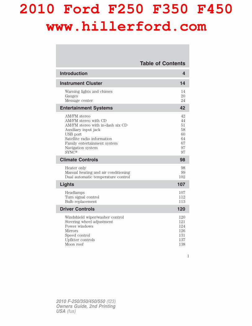
Introduction 4
Instrument Cluster 14
Warning lights and chimes 14Gauges 20Message center 24
Entertainment Systems 42
AM/FM stereo 42AM/FM stereo with CD 44AM/FM stereo with in-dash six CD 51Auxiliary input jack 58USB port 60Satellite radio information 64Family entertainment system 67Navigation system 97SYNC� 97
Climate Controls 98
Heater only 98Manual heating and air conditioning 99Dual automatic temperature control 102
Lights 107
Headlamps 107Turn signal control 112Bulb replacement 113
Driver Controls 120
Windshield wiper/washer control 120Steering wheel adjustment 121Power windows 124Mirrors 126Speed control 131Upfitter controls 137Moon roof 138
Table of Contents
1
2010 F-250/350/450/550 (f23)Owners Guide, 2nd PrintingUSA (fus)
2010 Ford F250 F350 F450www.hillerford.com
Locks and Security 148
Keys 148Locks 148Anti-theft system 159
Seating and Safety Restraints 164
Seating 164Safety restraints 173Airbags 185Child restraints 195
Tires, Wheels and Loading 217
Tire information 219Tire inflation 221Tire Pressure Monitoring System (TPMS) 237Vehicle loading 244Trailer towing 251Trailer brake controller-integrated 256Recreational towing 262
Driving 264
Starting 264Brakes 269Traction Control™ 271Transmission operation 275Reverse sensing system 280Rear-view camera system 282
Roadside Emergencies 303
Getting roadside assistance 303Hazard flasher control 304Fuel pump shut-off switch 305Fuses and relays 306Changing tires 315Wheel lug nut torque 330Jump starting 331Wrecker towing 336
Table of Contents
2
2010 F-250/350/450/550 (f23)Owners Guide, 2nd PrintingUSA (fus)
Customer Assistance 338
Reporting safety defects (U.S. only) 344Reporting safety defects (Canada only) 344
Cleaning 345
Maintenance and Specifications 355
Engine compartment 357Engine oil 360Battery 363Engine coolant 365Fuel information 371Air filter(s) 389Part numbers 390Maintenance product specifications and capacities 391Engine data 395
Accessories 398
Ford Extended Service Plan 400
Index 403
All rights reserved. Reproduction by any means, electronic or mechanicalincluding photocopying, recording or by any information storage and retrievalsystem or translation in whole or part is not permitted without writtenauthorization from Ford Motor Company. Ford may change the contents withoutnotice and without incurring obligation.
Copyright © 2009 Ford Motor Company
Table of Contents
3
2010 F-250/350/450/550 (f23)Owners Guide, 2nd PrintingUSA (fus)
CONGRATULATIONSCongratulations on acquiring your new Ford. Please take the time to getwell acquainted with your vehicle by reading this handbook. The moreyou know and understand about your vehicle, the greater the safety andpleasure you will derive from driving it.
For more information on Ford Motor Company and its products visit thefollowing website:
• In the United States: www.ford.com
• In Canada: www.ford.ca
• In Australia: www.ford.com.au
• In Mexico: www.ford.com.mx
Additional owner information is given in separate publications.
This Owner’s Guide describes every option and model variant availableand therefore some of the items covered may not apply to yourparticular vehicle. Furthermore, due to printing cycles it may describeoptions before they are generally available.
Remember to pass on this Owner’s Guide when reselling the vehicle. It isan integral part of the vehicle.
WARNING: Fuel pump shut-off switch: In the event of anaccident the safety switch will automatically cut off the fuel
supply to the engine. The switch can also be activated through suddenvibration (e.g. collision when parking). To reset the switch, refer to theFuel pump shut-off switch in the Roadside Emergencies chapter.
Introduction
4
2010 F-250/350/450/550 (f23)Owners Guide, 2nd PrintingUSA (fus)
SAFETY AND ENVIRONMENT PROTECTION
Warning symbols in this guide
How can you reduce the risk of personal injury to yourself or others? Inthis guide, answers to such questions are contained in commentshighlighted by the warning triangle symbol. These comments should beread and observed.
Warning symbols on your vehicle
When you see this symbol, it isimperative that you consult therelevant section of this guide beforetouching or attempting adjustmentof any kind.
Protecting the environmentWe must all play our part inprotecting the environment. Correctvehicle usage and the authorizeddisposal of waste, cleaning andlubrication materials are significantsteps towards this aim. Information in this respect is highlighted in thisguide with the tree symbol.
CALIFORNIA Proposition 65 Warning
WARNING: Engine exhaust, some of its constituents, andcertain vehicle components contain or emit chemicals known to
the State of California to cause cancer and birth defects or otherreproductive harm. In addition, certain fluids contained in vehicles andcertain products of component wear contain or emit chemicals knownto the State of California to cause cancer and birth defects or otherreproductive harm.
Introduction
5
2010 F-250/350/450/550 (f23)Owners Guide, 2nd PrintingUSA (fus)
PERCHLORATE MATERIALCertain components of this vehicle such as airbag modules, seat beltpretensioners, and button cell batteries may contain Perchlorate Material –Special handling may apply for service or vehicle end of life disposal. Seewww.dtsc.ca.gov/hazardouswaste/perchlorate.
BREAKING-IN YOUR VEHICLEYour vehicle does not need an extensive break-in. Try not to drivecontinuously at the same speed for the first 1,000 miles (1,600 km) ofnew vehicle operation. Vary your speed frequently in order to give themoving parts a chance to break in.
Drive your new vehicle at least 1,000 miles (1,600 km) before towing atrailer. For more detailed information about towing a trailer, refer toTrailer towing in the Tires, Wheels and Loading chapter.
Do not add friction modifier compounds or special break-in oils sincethese additives may prevent piston ring seating. See Engine oil in theMaintenance and Specifications chapter for more information on oilusage.
SPECIAL NOTICES
New Vehicle Limited WarrantyFor a detailed description of what is covered and what is not covered byyour vehicle’s New Vehicle Limited Warranty, refer to the WarrantyGuide/Customer Information Guide that is provided to you along withyour Owner’s Guide.
Special instructionsFor your added safety, your vehicle is fitted with sophisticated electroniccontrols.
WARNING: Please read the section Airbag SupplementalRestraint System (SRS) in the Seating and Safety Restraints
chapter. Failure to follow the specific warnings and instructions couldresult in personal injury.
WARNING: Front seat mounted rear-facing child or infant seatsshould NEVER be placed in front of an active passenger airbag.
Introduction
6
2010 F-250/350/450/550 (f23)Owners Guide, 2nd PrintingUSA (fus)
Notice to owners of diesel-powered vehiclesRead the 6.0 and 6.4 Liter Power Stroke Direct Injection Turbo DieselOwner’s Guide Supplement for information regarding correct operationand maintenance of your Diesel-powered light truck.
Notice to owners of pickup trucks and utility type vehicles
WARNING: Utility vehicles have a significantly higher rolloverrate than other types of vehicles.
Before you drive your vehicle, please read this Owner’s Guide carefully.Your vehicle is not a passenger car. As with other vehicles of this type,failure to operate this vehicle correctly may result in loss of vehiclecontrol, vehicle rollover, personal injury or death.
Using your vehicle with a snowplowFor more information and guidelines for using your vehicle with asnowplow, refer to the Driving chapter.
Using your vehicle as an ambulanceIf your light truck is equipped with the Ford Ambulance PreparationPackage, it may be utilized as an ambulance. Ford urges ambulancemanufacturers to follow the recommendations of the Ford IncompleteVehicle Manual, Ford Truck Body Builder’s Layout Book and theQualified Vehicle Modifiers (QVM) Guidelines as well as pertinentsupplements. For additional information, please contact the Truck BodyBuilders Advisory Service at http://www.fleet.ford.com/truckbbas/ andthen by selecting “Contact Us” or by phone at 1–877–840–4338.
Use of your Ford light truck as an ambulance, without the FordAmbulance Preparation Package voids the Ford New Vehicle LimitedWarranty and may void the Emissions Warranties. In addition, ambulanceusage without the preparation package could cause high underbodytemperatures, overpressurized fuel and a risk of spraying fuel whichcould lead to fires.
If your vehicle is equipped with the Ford Ambulance PreparationPackage, it will be indicated on the Safety Compliance CertificationLabel. The label is located on the driver’s side door pillar or on the rearedge of the driver’s door. You can determine whether the ambulancemanufacturer followed Ford’s recommendations by directly contactingthat manufacturer. Ford Ambulance Preparation Package is only availableon certain Diesel engine equipped vehicles.
Introduction
7
2010 F-250/350/450/550 (f23)Owners Guide, 2nd PrintingUSA (fus)
Using your vehicle as a stationary power source (PTO)Refer to the Driving chapter for more information and guidelines foroperating a vehicle equipped with an aftermarket power take-off system.
DATA RECORDING
Service Data RecordingService data recorders in your vehicle are capable of collecting andstoring diagnostic information about your vehicle. This potentiallyincludes information about the performance or status of various systemsand modules in the vehicle, such as engine, throttle, steering or brakesystems. In order to properly diagnose and service your vehicle, FordMotor Company, Ford of Canada, and service and repair facilities mayaccess or share among them vehicle diagnostic information receivedthrough a direct connection to your vehicle when diagnosing or servicingyour vehicle. For U.S. only (if equipped), if you choose to use the SYNC�Vehicle Health Report, you consent that certain diagnostic informationmay also be accessed electronically by Ford Motor Company and Fordauthorized service facilities, and that the diagnostic information may beused for any purpose. See your SYNC� supplement for more information.
Event Data RecordingOther modules in your vehicle — event data recorders — arecapable of collecting and storing data during a crash or nearcrash event. The recorded information may assist in theinvestigation of such an event. The modules may recordinformation about both the vehicle and the occupants, potentiallyincluding information such as:
• how various systems in your vehicle were operating;
• whether or not the driver and passenger seatbelts werebuckled;
• how far (if at all) the driver was depressing the acceleratorand/or the brake pedal;
• how fast the vehicle was traveling;
• where the driver was positioning the steering wheel; and
• longitude and latitude of vehicle at last location, using GPStechnology and advanced vehicle sensors.
Introduction
8
2010 F-250/350/450/550 (f23)Owners Guide, 2nd PrintingUSA (fus)
To access this information, special equipment must be directlyconnected to the recording modules. Ford Motor Company andFord of Canada do not access event data recorder informationwithout obtaining consent, unless pursuant to court order orwhere required by law enforcement, other government authoritiesor other third parties acting with lawful authority. Other partiesmay seek to access the information independently of Ford MotorCompany and Ford of Canada. To the extent that any lawpertaining to Event Data Recording applies to SYNC� or itsfeatures, please note the following: Once 911 Assist (if equipped)is enabled (set ON), 911 Assist may, through any paired andconnected cell phone, disclose to emergency services that thevehicle has been in a crash involving the deployment of an airbagor, in certain vehicles, the activation of the fuel pump shut-off.Certain versions or updates to 911 Assist may also be capable ofelectronically or verbally disclosing to 911 operators the vehiclelocation, and/or other details about the vehicle or crash to assist911 operators to provide the most appropriate emergencyservices. If you do not want to disclose this information, do notactivate the feature. See your SYNC� supplement for moreinformation. Additionally, when you connect to Traffic, Directionsand Information (if equipped, U.S. only), the service uses GPStechnology and advanced vehicle sensors to collect the vehicle’scurrent location, travel direction, and speed (“vehicle travelinformation”) only to help provide you with the directions, trafficreports, or business searches you request. If you do not wantFord or its vendors to receive this information, do not activatethe service. Ford Motor Company and the vendors it uses toprovide you with this information do not store your vehicle travelinformation. For more information, see Traffic, Directions andInformation, Terms and Conditions. See your SYNC� supplementfor more information.
Introduction
9
2010 F-250/350/450/550 (f23)Owners Guide, 2nd PrintingUSA (fus)
Vehicle Modification Data RecordingSome aftermarket products may cause severe engine and/or transmissiondamage; refer to the What is not covered section in The new vehiclelimited warranty for your vehicle chapter of your vehicle’s WarrantyGuide for more information. Some vehicles are equipped withPowertrain Control Systems that can detect and store information aboutvehicle modifications that, for example, increase horsepower and torqueoutput; this information cannot be erased and will stay in the system’smemory even if the modification is removed. When a dealer or repairfacility works on your vehicle, it may be necessary for them to access theinformation in the Powertrain Control System. This information will likelyidentify if any unauthorized modifications have been made to the system,which may be used to determine if the warranty has been violated and ifrepairs will be covered by warranty.
CELL PHONE USEThe use of Mobile Communications Equipment has become increasinglyimportant in the conduct of business and personal affairs. However,drivers must not compromise their own or others’ safety when usingsuch equipment. Mobile Communications can enhance personal safetyand security when appropriately used, particularly in emergencysituations. Safety must be paramount when using mobile communicationsequipment to avoid negating these benefits.
Mobile Communication Equipment includes, but is not limited to cellularphones, pagers, portable email devices, in-vehicle communicationssystems, telematics devices and portable two-way radios.
WARNING: Driving while distracted can result in loss of vehiclecontrol, accident and injury. Ford strongly recommends that
drivers use extreme caution when using any device that may take theirfocus off the road. The driver’s primary responsibility is the safeoperation of their vehicle. Only use cell phones and other devices notessential to the driving task when it is safe to do so.
Introduction
10
2010 F-250/350/450/550 (f23)Owners Guide, 2nd PrintingUSA (fus)
EXPORT UNIQUE (NON–UNITED STATES/CANADA) VEHICLESPECIFIC INFORMATIONFor your particular global region, your vehicle may be equipped withfeatures and options that are different from the features and options thatare described in this Owner’s Guide. A market unique supplement maybe supplied that complements this book. By referring to the marketunique supplement, if provided, you can properly identify those features,recommendations and specifications that are unique to your vehicle. ThisOwner’s Guide is written primarily for the U.S. and Canadian Markets.Features or equipment listed as standard may be different on units builtfor Export. Refer to this Owner’s Guide for all other requiredinformation and warnings.
Introduction
11
2010 F-250/350/450/550 (f23)Owners Guide, 2nd PrintingUSA (fus)
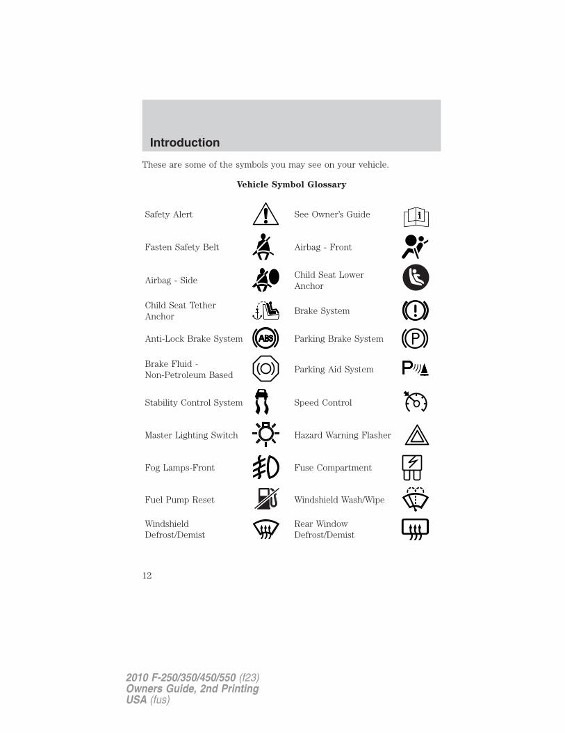
These are some of the symbols you may see on your vehicle.
Vehicle Symbol Glossary
Safety Alert See Owner’s Guide
Fasten Safety Belt Airbag - Front
Airbag - SideChild Seat LowerAnchor
Child Seat TetherAnchor
Brake System
Anti-Lock Brake System Parking Brake System
Brake Fluid -Non-Petroleum Based
Parking Aid System
Stability Control System Speed Control
Master Lighting Switch Hazard Warning Flasher
Fog Lamps-Front Fuse Compartment
Fuel Pump Reset Windshield Wash/Wipe
WindshieldDefrost/Demist
Rear WindowDefrost/Demist
Introduction
12
2010 F-250/350/450/550 (f23)Owners Guide, 2nd PrintingUSA (fus)
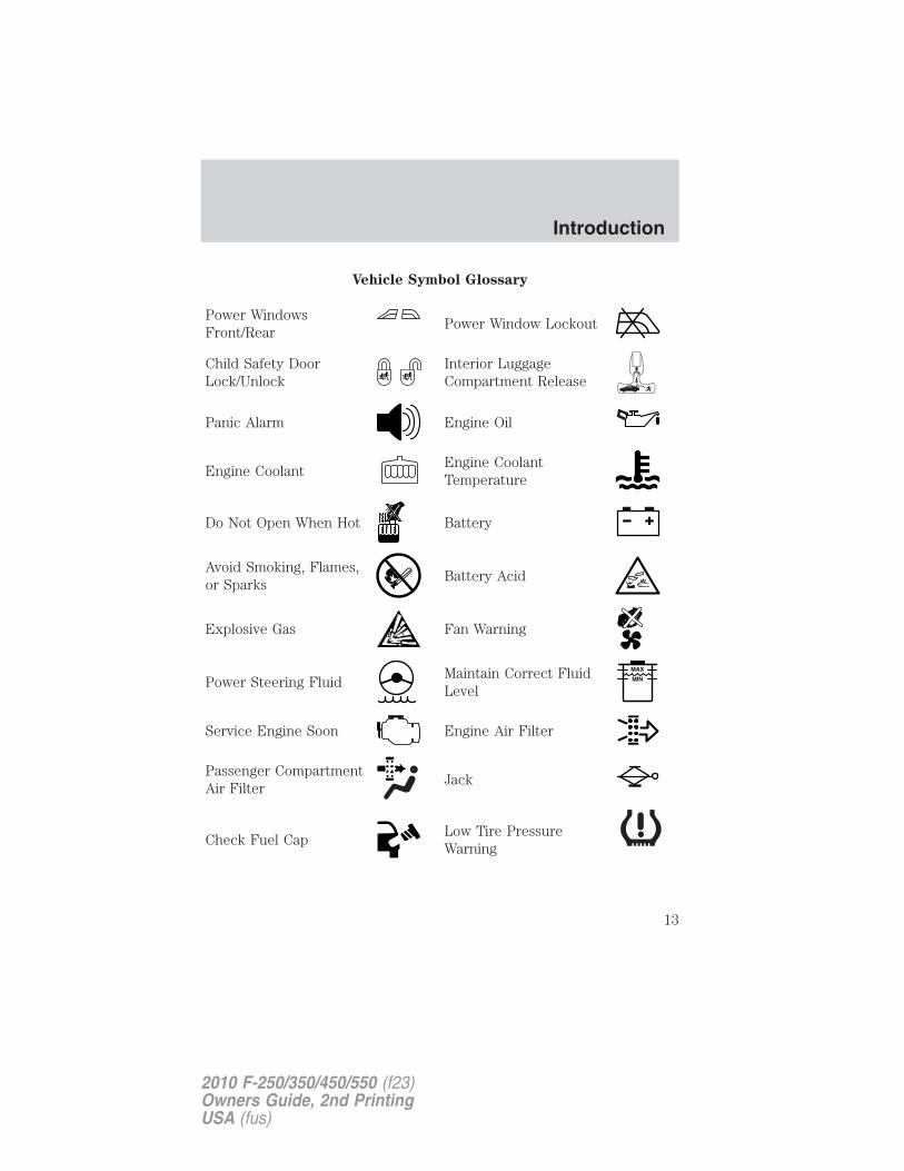
Vehicle Symbol Glossary
Power WindowsFront/Rear
Power Window Lockout
Child Safety DoorLock/Unlock
Interior LuggageCompartment Release
Panic Alarm Engine Oil
Engine CoolantEngine CoolantTemperature
Do Not Open When Hot Battery
Avoid Smoking, Flames,or Sparks
Battery Acid
Explosive Gas Fan Warning
Power Steering FluidMaintain Correct FluidLevel
MAX
MIN
Service Engine Soon Engine Air Filter
Passenger CompartmentAir Filter
Jack
Check Fuel CapLow Tire PressureWarning
Introduction
13
2010 F-250/350/450/550 (f23)Owners Guide, 2nd PrintingUSA (fus)
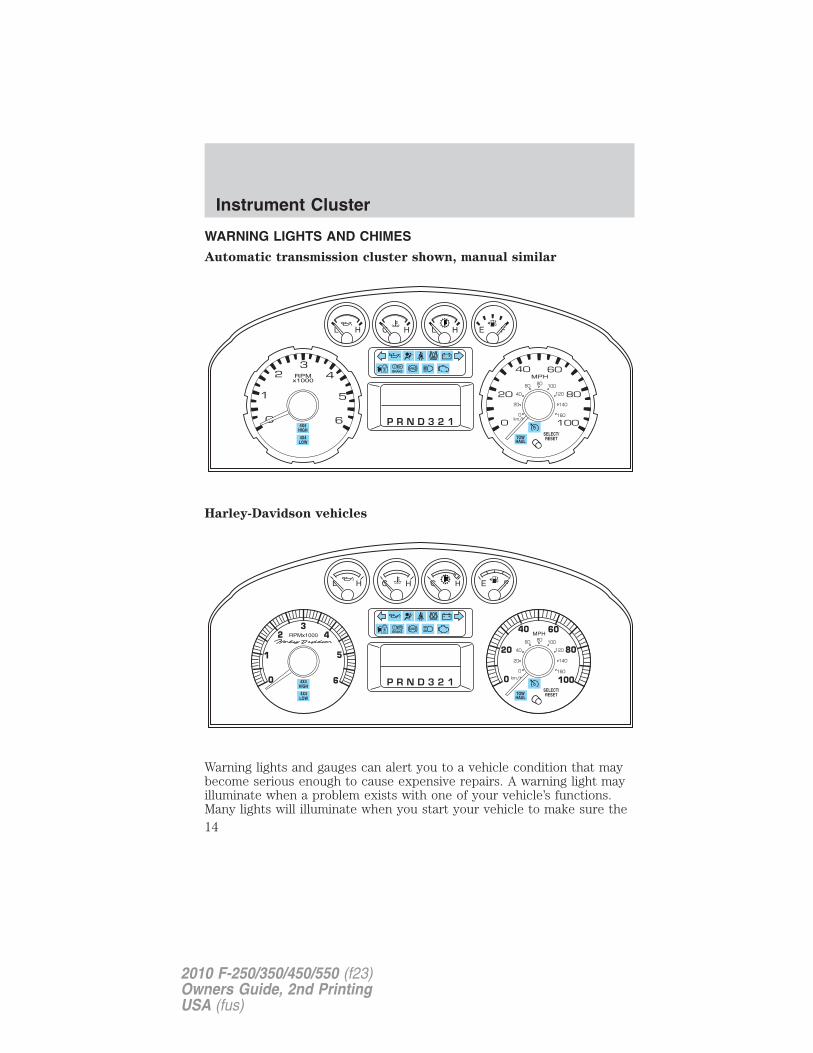
WARNING LIGHTS AND CHIMES
Automatic transmission cluster shown, manual similar
Harley-Davidson vehicles
Warning lights and gauges can alert you to a vehicle condition that maybecome serious enough to cause expensive repairs. A warning light mayilluminate when a problem exists with one of your vehicle’s functions.Many lights will illuminate when you start your vehicle to make sure the
Instrument Cluster
14
2010 F-250/350/450/550 (f23)Owners Guide, 2nd PrintingUSA (fus)
bulbs work. If any light remains on after starting the vehicle, refer to therespective system warning light description for additional information.
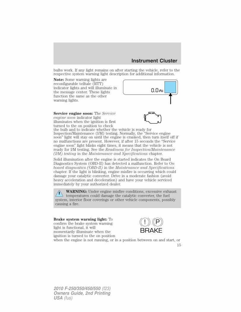
Note: Some warning lights arereconfigurable telltale (RTT)indicator lights and will illuminate inthe message center. These lightsfunction the same as the otherwarning lights.
Service engine soon: The Serviceengine soon indicator lightilluminates when the ignition is firstturned to the on position to checkthe bulb and to indicate whether the vehicle is ready forInspection/Maintenance (I/M) testing. Normally, the “Service enginesoon” light will stay on until the engine is cranked, then turn itself off ifno malfunctions are present. However, if after 15 seconds the “Serviceengine soon” light blinks eight times, it means that the vehicle is notready for I/M testing. See the Readiness for Inspection/Maintenance(I/M) testing in the Maintenance and Specifications chapter.
Solid illumination after the engine is started indicates the On BoardDiagnostics System (OBD-II) has detected a malfunction. Refer to Onboard diagnostics (OBD-II) in the Maintenance and Specificationschapter. If the light is blinking, engine misfire is occurring which coulddamage your catalytic converter. Drive in a moderate fashion (avoidheavy acceleration and deceleration) and have your vehicle servicedimmediately by your authorized dealer.
WARNING: Under engine misfire conditions, excessive exhausttemperatures could damage the catalytic converter, the fuel
system, interior floor coverings or other vehicle components, possiblycausing a fire.
Brake system warning light: Toconfirm the brake system warninglight is functional, it willmomentarily illuminate when theignition is turned to the on positionwhen the engine is not running, or in a position between on and start, or
P!BRAKE
Instrument Cluster
15
2010 F-250/350/450/550 (f23)Owners Guide, 2nd PrintingUSA (fus)
by applying the parking brake when the ignition is turned to the onposition. If the brake system warning light does not illuminate at thistime, seek service immediately from your authorized dealer. Illuminationafter releasing the parking brake indicates low brake fluid level and thebrake system should be inspected immediately by your servicingauthorized dealer.
WARNING: Driving a vehicle with the brake system warninglight on is dangerous. A significant decrease in braking
performance may occur. It will take you longer to stop the vehicle.Have the vehicle checked by your authorized dealer immediately.Driving extended distances with the parking brake engaged can causebrake failure and the risk of personal injury.
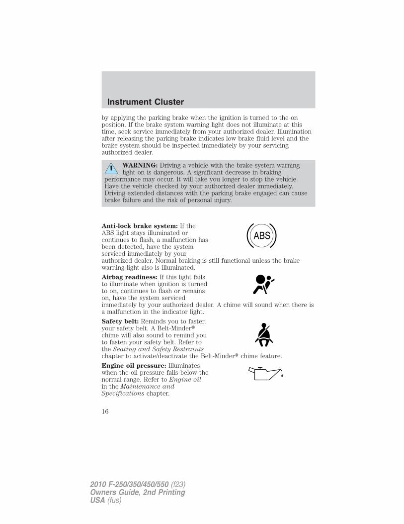
Anti-lock brake system: If theABS light stays illuminated orcontinues to flash, a malfunction hasbeen detected, have the systemserviced immediately by yourauthorized dealer. Normal braking is still functional unless the brakewarning light also is illuminated.
Airbag readiness: If this light failsto illuminate when ignition is turnedto on, continues to flash or remainson, have the system servicedimmediately by your authorized dealer. A chime will sound when there isa malfunction in the indicator light.
Safety belt: Reminds you to fastenyour safety belt. A Belt-Minder�chime will also sound to remind youto fasten your safety belt. Refer tothe Seating and Safety Restraintschapter to activate/deactivate the Belt-Minder� chime feature.
Engine oil pressure: Illuminateswhen the oil pressure falls below thenormal range. Refer to Engine oilin the Maintenance andSpecifications chapter.
ABS
Instrument Cluster
16
2010 F-250/350/450/550 (f23)Owners Guide, 2nd PrintingUSA (fus)
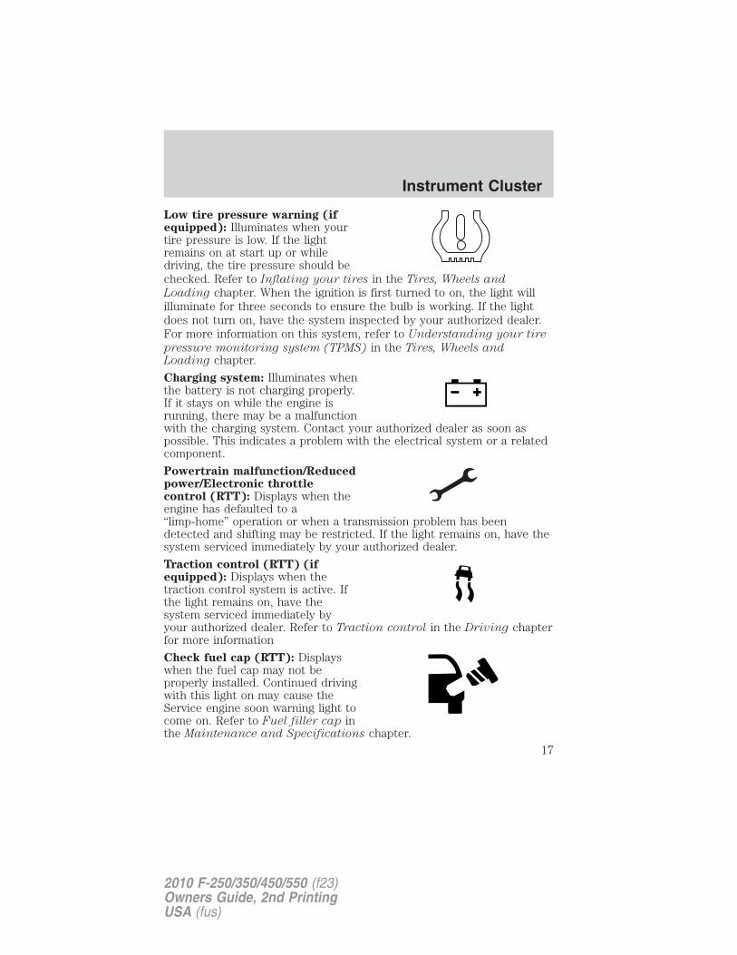
Low tire pressure warning (ifequipped): Illuminates when yourtire pressure is low. If the lightremains on at start up or whiledriving, the tire pressure should bechecked. Refer to Inflating your tires in the Tires, Wheels and
Loading chapter. When the ignition is first turned to on, the light willilluminate for three seconds to ensure the bulb is working. If the lightdoes not turn on, have the system inspected by your authorized dealer.For more information on this system, refer to Understanding your tire
pressure monitoring system (TPMS) in the Tires, Wheels andLoading chapter.
Charging system: Illuminates whenthe battery is not charging properly.If it stays on while the engine isrunning, there may be a malfunctionwith the charging system. Contact your authorized dealer as soon aspossible. This indicates a problem with the electrical system or a relatedcomponent.
Powertrain malfunction/Reducedpower/Electronic throttlecontrol (RTT): Displays when theengine has defaulted to a“limp-home” operation or when a transmission problem has beendetected and shifting may be restricted. If the light remains on, have thesystem serviced immediately by your authorized dealer.
Traction control (RTT) (ifequipped): Displays when thetraction control system is active. Ifthe light remains on, have thesystem serviced immediately byyour authorized dealer. Refer to Traction control in the Driving chapterfor more information
Check fuel cap (RTT): Displayswhen the fuel cap may not beproperly installed. Continued drivingwith this light on may cause theService engine soon warning light tocome on. Refer to Fuel filler cap inthe Maintenance and Specifications chapter.
Instrument Cluster
17
2010 F-250/350/450/550 (f23)Owners Guide, 2nd PrintingUSA (fus)
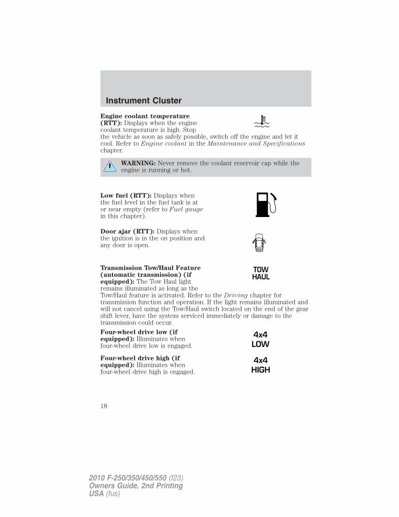
Engine coolant temperature(RTT): Displays when the enginecoolant temperature is high. Stopthe vehicle as soon as safely possible, switch off the engine and let itcool. Refer to Engine coolant in the Maintenance and Specificationschapter.
WARNING: Never remove the coolant reservoir cap while theengine is running or hot.
Low fuel (RTT): Displays whenthe fuel level in the fuel tank is ator near empty (refer to Fuel gaugein this chapter).
Door ajar (RTT): Displays whenthe ignition is in the on position andany door is open.
Transmission Tow/Haul Feature(automatic transmission) (ifequipped): The Tow Haul lightremains illuminated as long as theTow/Haul feature is activated. Refer to the Driving chapter fortransmission function and operation. If the light remains illuminated andwill not cancel using the Tow/Haul switch located on the end of the gearshift lever, have the system serviced immediately or damage to thetransmission could occur.
Four-wheel drive low (ifequipped): Illuminates whenfour-wheel drive low is engaged.
Four-wheel drive high (ifequipped): Illuminates whenfour-wheel drive high is engaged.
4x4LOW
4x4HIGH
Instrument Cluster
18
2010 F-250/350/450/550 (f23)Owners Guide, 2nd PrintingUSA (fus)
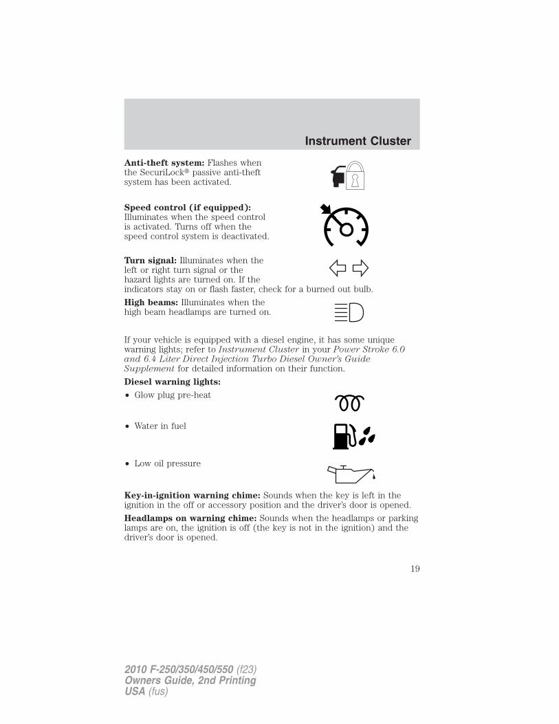
Anti-theft system: Flashes whenthe SecuriLock� passive anti-theftsystem has been activated.
Speed control (if equipped):Illuminates when the speed controlis activated. Turns off when thespeed control system is deactivated.
Turn signal: Illuminates when theleft or right turn signal or thehazard lights are turned on. If theindicators stay on or flash faster, check for a burned out bulb.
High beams: Illuminates when thehigh beam headlamps are turned on.
If your vehicle is equipped with a diesel engine, it has some uniquewarning lights; refer to Instrument Cluster in your Power Stroke 6.0and 6.4 Liter Direct Injection Turbo Diesel Owner’s GuideSupplement for detailed information on their function.
Diesel warning lights:
• Glow plug pre-heat
• Water in fuel
• Low oil pressure
Key-in-ignition warning chime: Sounds when the key is left in theignition in the off or accessory position and the driver’s door is opened.
Headlamps on warning chime: Sounds when the headlamps or parkinglamps are on, the ignition is off (the key is not in the ignition) and thedriver’s door is opened.
Instrument Cluster
19
2010 F-250/350/450/550 (f23)Owners Guide, 2nd PrintingUSA (fus)
Parking brake on warning chime: Sounds when the parking brake isset, the engine is running and the vehicle is driven more than 3 mph(5 km/h). If the warning remains on after the parking brake is off,contact your authorized dealer as soon as possible.
Turn signal chime: Sounds when the turn signal lever has beenactivated to signal a turn and not turned off after the vehicle is drivenmore than 2 miles (3.2 km).
Message center activation chime: Sounds when some warningmessages appears in the message center display for the first time.
Overspeed chime (if equipped): Sounds when the vehicle speedreaches 75 mph (120 km/h) or higher.
Airbag secondary warning chime: Sounds to inform the driver, in theevent that the airbag readiness warning lamp is inoperable, that there isa fault in the supplemental restraint system.
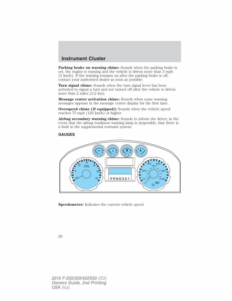
GAUGES
Speedometer: Indicates the current vehicle speed.
Instrument Cluster
20
2010 F-250/350/450/550 (f23)Owners Guide, 2nd PrintingUSA (fus)
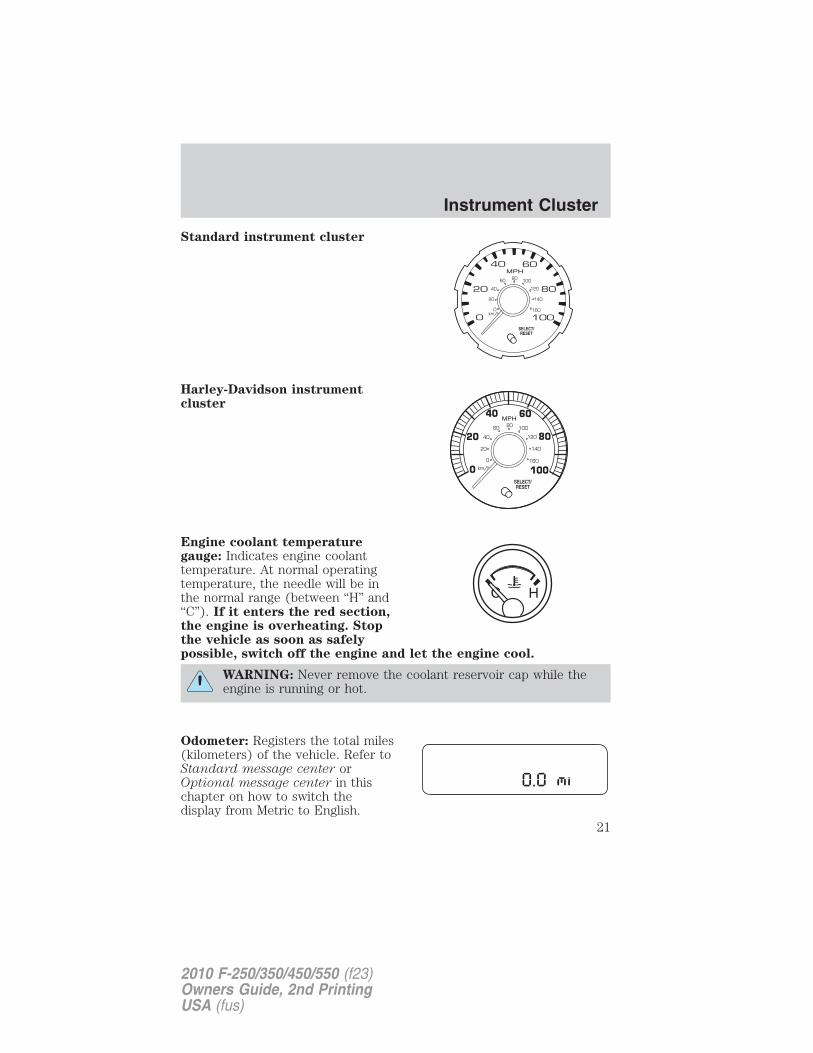
Standard instrument cluster
Harley-Davidson instrumentcluster
Engine coolant temperaturegauge: Indicates engine coolanttemperature. At normal operatingtemperature, the needle will be inthe normal range (between “H” and“C”). If it enters the red section,the engine is overheating. Stopthe vehicle as soon as safelypossible, switch off the engine and let the engine cool.
WARNING: Never remove the coolant reservoir cap while theengine is running or hot.
Odometer: Registers the total miles(kilometers) of the vehicle. Refer toStandard message center orOptional message center in thischapter on how to switch thedisplay from Metric to English.
Instrument Cluster
21
2010 F-250/350/450/550 (f23)Owners Guide, 2nd PrintingUSA (fus)
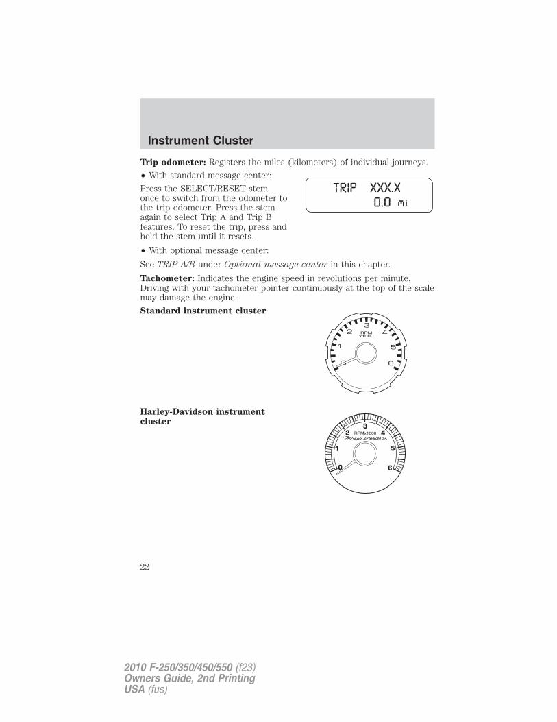
Trip odometer: Registers the miles (kilometers) of individual journeys.
• With standard message center:
Press the SELECT/RESET stemonce to switch from the odometer tothe trip odometer. Press the stemagain to select Trip A and Trip Bfeatures. To reset the trip, press andhold the stem until it resets.
• With optional message center:
See TRIP A/B under Optional message center in this chapter.
Tachometer: Indicates the engine speed in revolutions per minute.Driving with your tachometer pointer continuously at the top of the scalemay damage the engine.
Standard instrument cluster
Harley-Davidson instrumentcluster
Instrument Cluster
22
2010 F-250/350/450/550 (f23)Owners Guide, 2nd PrintingUSA (fus)
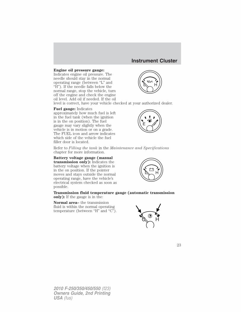
Engine oil pressure gauge:Indicates engine oil pressure. Theneedle should stay in the normaloperating range (between “L” and“H”). If the needle falls below thenormal range, stop the vehicle, turnoff the engine and check the engineoil level. Add oil if needed. If the oillevel is correct, have your vehicle checked at your authorized dealer.
Fuel gauge: Indicatesapproximately how much fuel is leftin the fuel tank (when the ignitionis in the on position). The fuelgauge may vary slightly when thevehicle is in motion or on a grade.The FUEL icon and arrow indicateswhich side of the vehicle the fuelfiller door is located.
Refer to Filling the tank in the Maintenance and Specificationschapter for more information.
Battery voltage gauge (manualtransmission only): Indicates thebattery voltage when the ignition isin the on position. If the pointermoves and stays outside the normaloperating range, have the vehicle’selectrical system checked as soon aspossible.
Transmission fluid temperature gauge (automatic transmissiononly): If the gauge is in the:
Normal area– the transmissionfluid is within the normal operatingtemperature (between “H” and “C”).
Instrument Cluster
23
2010 F-250/350/450/550 (f23)Owners Guide, 2nd PrintingUSA (fus)
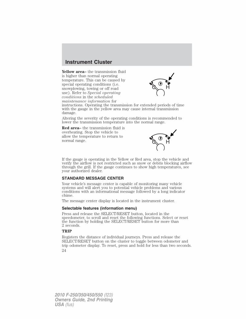
Yellow area– the transmission fluidis higher than normal operatingtemperature. This can be caused byspecial operating conditions (i.e.snowplowing, towing or off roaduse). Refer to Special operatingconditions in the scheduledmaintenance information forinstructions. Operating the transmission for extended periods of timewith the gauge in the yellow area may cause internal transmissiondamage.Altering the severity of the operating conditions is recommended tolower the transmission temperature into the normal range.
Red area– the transmission fluid isoverheating. Stop the vehicle toallow the temperature to return tonormal range.
If the gauge is operating in the Yellow or Red area, stop the vehicle andverify the airflow is not restricted such as snow or debris blocking airflowthrough the grill. If the gauge continues to show high temperatures, seeyour authorized dealer.
STANDARD MESSAGE CENTERYour vehicle’s message center is capable of monitoring many vehiclesystems and will alert you to potential vehicle problems and variousconditions with an informational message followed by a long indicatorchime.The message center display is located in the instrument cluster.
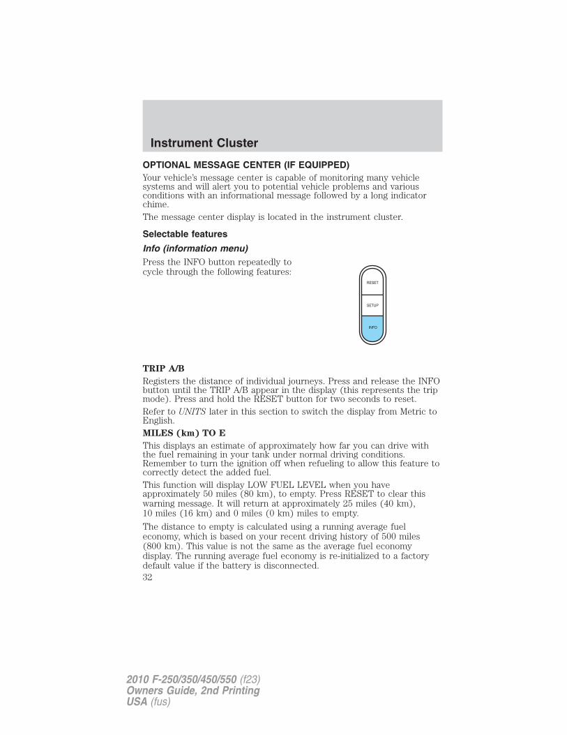
Selectable features (information menu)Press and release the SELECT/RESET button, located in thespeedometer, to scroll and reset the following functions. Select or resetthe function by holding the SELECT/RESET button for more than2 seconds.
TRIP
Registers the distance of individual journeys. Press and release theSELECT/RESET button on the cluster to toggle between odometer andtrip odometer display. To reset, press and hold for less than two seconds.
Instrument Cluster
24
2010 F-250/350/450/550 (f23)Owners Guide, 2nd PrintingUSA (fus)
ENG HRS
Registers the accumulated time the engine has been running.MILES (km) TO E
This displays an estimate of approximately how far you can drive withthe fuel remaining in your tank under normal driving conditions.Remember to turn the ignition off when refueling to allow this feature tocorrectly detect the added fuel.
This function will display LOW FUEL LEVEL when you haveapproximately 50 miles (80 km), to empty. Press RESET to clear thiswarning message. It will return at approximately 25 miles (40 km),10 miles (16 km) and 0 miles (0 km) to empty.
The distance to empty is calculated using a running average fueleconomy, which is based on your recent driving history of 500 miles(800 km). This value is not the same as the average fuel economydisplay. The running average fuel economy is re-initialized to a factorydefault value if the battery is disconnected.
XX.X MPG (L/100km)
Average fuel economy displays your average fuel economy in miles/gallonor liters/100 km.
If you calculate your average fuel economy by dividing distance traveledby gallons of fuel used (liters of fuel used by 100 kilometers traveled),your figure may be different than displayed for the following reasons:
• Your vehicle was not perfectly level during fill-up
• Differences in the automatic shut-off points on the fuel pumps atservice stations
• Variations in top-off procedure from one fill-up to another
• Rounding of the displayed values to the nearest 0.1 gallon (liter)
1. Drive the vehicle at least 5 miles (8 km) with the speed controlsystem engaged to display a stabilized average.
2. Record the highway fuel economy for future reference.
It is important to press the SELECT/RESET button (press and hold theSELECT/RESET button for two seconds in order to reset the function)after setting the speed control to get accurate highway fuel economyreadings.
TBC GAIN (if equipped)
Displays the level of trailer brake gain or if the trailer is not connected.
Instrument Cluster
25
2010 F-250/350/450/550 (f23)Owners Guide, 2nd PrintingUSA (fus)
Setup menu (vehicle customization and vehicle system check)HOLD RESET FOR SETUP MENU
Press and hold the SELECT/RESET button to get into the setup menusequence for the following displays:Note: When returning to the setup menu and a non-English languagehas been selected, HOLD RESET FOR ENGLISH will be displayed tochange back to English. Press and hold the SELECT/RESET button tochange back to English.OIL LIFE
This displays the remaining oil life.An oil change is required whenever indicated by the message center andaccording to the recommended maintenance schedule. USE ONLYRECOMMENDED ENGINE OILS.To reset the oil monitoring system to 100% after each oil change(approximately 7,500 miles [12,000 km] or 12 months) perform thefollowing:1. Press and release the setup button to display “OIL LIFE XXX% HOLDRESET = NEW”.2. Press and hold the SELECT/RESET stem for two seconds and releaseto reset the oil life to 100%.Note: To change oil life 100% miles value from 7,500 miles (12,000 km)or 12 months to another value, proceed to Step 3.
3. Once “OIL LIFE SET TO XXX%” is displayed, release and press theSELECT/RESET stem to change the Oil Life Start Value. Each releaseand press will reduce the value by 10%.
Note: Oil life start value of 100% equals 7,500 miles (12,000 km) or12 months. For example, setting oil life start value to 60% sets the oillife start value to 4,500 miles (7,200 km) and 219 days.
UNITS
Displays the current units English or Metric.
Press and hold the SELECT/RESET button to change from English toMetric.
Press the SELECT/RESET button for the next setup menu item or waitfor more than four seconds to return to the info menu.
PARK AID (if equipped)
This feature sounds a warning tone to warn the driver of obstacles nearthe rear bumper, and functions only when R (Reverse) gear is selected.
Instrument Cluster
26
2010 F-250/350/450/550 (f23)Owners Guide, 2nd PrintingUSA (fus)
Press and hold the SELECT/RESET stem to turn this feature on or off.(You can also choose to turn this feature on/off when the vehicle isplaced in reverse.)Press the SELECT/RESET stem for the next setup menu item or wait formore than four seconds to return to the info menu.LANGUAGE = ENGLISH / SPANISH / FRENCH
Allows you to choose which language the message center will display in.Selectable languages are English, Spanish, or French.Note: When entering the setup menu and a non-English language hasbeen selected, “PRESS RESET FOR ENGLISH” will be displayed tochange back to English.Press and hold the SELECT/RESET button to select a new language.Selectable languages are English, Spanish and FrenchPress and hold the SELECT/RESET button for two seconds to set thelanguage choice.Press the SELECT/RESET button for the next setup menu item or waitfor more than four seconds to return to the info menu.
HOLD RESET FOR SYSTEM CHECK
Press and hold the SELECT/RESET button to select SYSTEM CHECKwhen HOLD RESET FOR SYSTEM CHECK is displayed in the messagecenter. For each of the monitored systems, the message center willindicate either an OK message or a warning message for two seconds.Pressing the SELECT/RESET button cycles the message center througheach of the systems being monitored.
The sequence of the system check report and how it appears in themessage center is as follows:
1. XXX% OIL LIFE
2. ENGINE HOURS
3. ENGINE IDLE HOURS (Diesel engine only)
4. CHARGING SYSTEM
5. DOOR AJAR
6. BRAKE SYSTEM
7. XX MILES TO E FUEL LEVEL XXX
System warningsSystem warnings alert you to possible problems or malfunctions in yourvehicle’s operating systems.
Instrument Cluster
27
2010 F-250/350/450/550 (f23)Owners Guide, 2nd PrintingUSA (fus)
In the event of a multiple warning situation, the message center willcycle the display to show all warnings by displaying each one for fourseconds.The message center will display the last selected feature if there are nomore warning messages.Types of messages and warnings:• Some messages will appear briefly to inform you of something you
may need to take action on or be informed of.
• Some messages will appear once and then again when the vehicle isrestarted.
• Some messages will reappear after clearing or being reset if a problemor condition is still present and needs your attention.
• Some messages can be acknowledged and reset by pressing theSELECT/RESET button. This allows you to use the full messagecenter functionality by clearing the message.
PARK BRAKE ENGAGED — Displayed when the parking brake isapplied (or not fully released).
CHECK BRAKE SYSTEM — Displayed when a fault has been detectedby the ABS module.
DRIVER DOOR AJAR — Displayed when the driver’s door is notcompletely closed.
PASSENGER DOOR AJAR — Displayed when the passenger’s door isnot completely closed.
REAR LEFT DOOR AJAR — Displayed when the rear left door is notcompletely closed.
REAR RIGHT DOOR AJAR — Displayed when the rear right door isnot completely closed.
XXX MILES TO E FUEL LEVEL LOW — Displayed as an earlyreminder of a low fuel condition.
CHECK PARK AID (if equipped) — Displayed when the transmissionis in R (Reverse) and the reverse sensing system (park aid) is disabled.
TO STOP ALARM START VEHICLE (if equipped) — Displayedwhen the perimeter alarm system is armed and the vehicle is enteredusing the key on the driver’s side door. In order to prevent the perimeteralarm system from triggering, the ignition must be turned to start or onbefore the 12–second chime expires. See Perimeter alarm system in theLocks and Security chapter.
Instrument Cluster
28
2010 F-250/350/450/550 (f23)Owners Guide, 2nd PrintingUSA (fus)
WIRING FAULT ON TRAILER (if equipped) — Displayed if thereare certain faults in the vehicle wiring and trailer wiring/brake system.Refer to Trailer towing in the Tires, Wheels and Loading chapter formore information.TRAILER BRAKE MODULE FAULT (if equipped) — Displayed andaccompanied by a single chime, in response to faults sensed by the TBC.Refer to Trailer towing in the Tires, Wheels and Loading chapter formore information.
TRAILER DISCONNECTED (if equipped) — Displayed when atrailer connection becomes disconnected, either intentionally orunintentionally, and has been sensed during a given ignition cycle. Referto Trailer towing in the Tires, Wheels and Loading chapter for moreinformation.
BRAKE FLUID LEVEL LOW — Indicates the brake fluid level is lowand the brake system should be inspected immediately. Refer to Brakefluid in the Maintenance and Specifications chapter.
LOW TIRE PRESSURE (if equipped) — Displayed when one or moretires on your vehicle have low tire pressure. Refer to Inflating yourtires in the Tires, Wheels and Loading chapter.
TIRE PRESSURE MONITOR FAULT (if equipped) — Displayedwhen the Tire Pressure Monitoring System is malfunctioning. If thewarning stays on or continues to come on, contact your authorizeddealer as soon as possible.
TIRE PRESSURE SENSOR FAULT (if equipped) — Displayed whena tire pressure sensor is malfunctioning, or your spare tire is in use. Formore information on how the system operates under these conditions,refer to Understanding Your Tire Pressure Monitoring System(TPMS) in the Tires, Wheels and Loading chapter. If the warning stayson or continues to come on, contact your authorized dealer as soon aspossible.
ENGINE WARMING PLEASE WAIT XX (Diesel engine only) —Displayed in extremely cold weather, typically below –15°F (–26°C), ifthe engine block heater is not utilized. The engine will not respond toaccelerator pedal movement for 30 seconds; this is done so the engine oilcan be properly circulated to avoid engine damage from lack oflubrication. A timer will begin a countdown from 30 seconds. Once thecounter has reached 0 (zero) seconds, OK TO DRIVE will be displayedand the engine will respond to accelerator pedal movement. Refer toyour Power Stroke 6.0 and 6.4 Liter Direct Injection Turbo DieselOwner’s Guide Supplement for more information.
Instrument Cluster
29
2010 F-250/350/450/550 (f23)Owners Guide, 2nd PrintingUSA (fus)
OK TO DRIVE (Diesel engine only) — Displayed when the timecounter has reached 0 (zero) and the engine is sufficiently warm enoughto drive in extremely cold weather (refer to the engine warming pleasewait message description mentioned previously). Refer to your PowerStroke 6.0 and 6.4 Liter Direct Injection Turbo Diesel Owner’s GuideSupplement for more information.DRAIN WATER SEPARATOR (Diesel engine only) — Displayedwhen the water separator has reached a predetermined capacity andneeds to be drained. Refer to your Power Stroke 6.0 and 6.4 LiterDirect Injection Turbo Diesel Owner’s Guide Supplement for moreinformation.ENGINE TURNS OFF IN XX (Diesel engine only) — Displayedwhen the vehicle is in the final 30 seconds of a countdown to where theengine will intentionally be turned off by the PCM. The diesel engineshutdown is a (regulatory) requirement which may be required of aparticular diesel vehicle for sale in states requiring this feature. Refer toyour Power Stroke 6.0 and 6.4 Liter Direct Injection Turbo DieselOwner’s Guide Supplement for more information.
ENGINE TURNED OFF (Diesel engine only) — Displayed after the30 second countdown. Refer to your Power Stroke 6.0 and 6.4 LiterDirect Injection Turbo Diesel Owner’s Guide Supplement for moreinformation.
DRIVE TO CLEAN EXHAUST FILTER (Diesel engine only) —Displayed when the Diesel Particulate Filter (DPF) is full of particles(exhaust soot) and the vehicle is not being operated in a manner toallow normal cleaning. This message will stay on until the exhaust filtercleaning has begun, at which time the CLEANING EXHAUST FILTERmessage will be displayed. It is recommended the vehicle operator drivethe vehicle above 30 mph (48 km/h) until the CLEANING EXHAUSTFILTER message turns off. This message is NORMAL. Refer to yourPower Stroke 6.0 and 6.4 Liter Direct Injection Turbo Diesel Owner’sGuide Supplement for more information.Note: If this message is ignored, your vehicle will continue to fill theDiesel Particulate Filter (DPF) with particles (exhaust soot). If cleaningis not permitted, the light will illuminate and engine power may belimited. If the vehicle is still not operated in a manner to allow cleaning,the service engine soon light will illuminate and engine power willbe further limited. Dealer service will then be required to restore yourvehicle to full-power operation.
Note: Diesel Particulate Filter (DPF) regeneration will not initiate at idleor in Power-Take-Off (PTO) mode. When DRIVE TO CLEAN EXHAUST
Instrument Cluster
30
2010 F-250/350/450/550 (f23)Owners Guide, 2nd PrintingUSA (fus)
FILTER is displayed in the message center, PTO and/or StationaryElevated Idle Control (SEIC) must be disengaged/inactive in order toproperly clean the DPF. The vehicle must be driven until the CLEANINGEXHAUST FILTER message turns off.CLEANING EXHAUST FILTER (Diesel engine only) — Displayedwhen the vehicle has entered the cleaning mode. Various engine actionswill raise the exhaust temperature in the Diesel Particulate Filter (DPF)system to burn off the particles (exhaust soot). After the particles areburned off, the exhaust temperature will fall back to normal levels. Thismessage is NORMAL. Refer to your Power Stroke 6.0 and 6.4 LiterDirect Injection Turbo Diesel Owner’s Guide Supplement for moreinformation.
WARNING: When the CLEANING EXHAUST FILTER messageappears in the message center, do not park near flammable
materials, vapors or structures until filter cleaning is complete.
EXHAUST FILTER DRIVE COMPLETE (Diesel engine only) —Displayed when the Diesel Particulate Filter (DPF) has been adequatelycleaned after the DRIVE TO CLEAN EXHAUST FILTER followed byCLEANING EXHAUST FILTER messages have been displayed. Thismessage is NORMAL. Refer to your Power Stroke 6.0 and 6.4 LiterDirect Injection Turbo Diesel Owner’s Guide Supplement for moreinformation.
STOP SAFELY NOW (Diesel engine only) — Displayed and a chimesounds when the vehicle exhaust system temperature exceeds intendedoperating range. If this warning occurs, engine power is reduced and theengine will shut down when the vehicle speed is below 3 mph (5 km/h).Stop the vehicle as soon as safely possible and contact yourauthorized dealer. Depending on the severity of the over-temperaturecondition, the vehicle may not restart after cycling the ignition off. If thevehicle restarts, there may be limited power. If the exhaustover-temperature condition reoccurs, the message center will displaySTOP SAFELY NOW, the chime will sound, and engine power will bereduced again and shut down below 3 mph (5 km/h). Refer to yourPower Stroke 6.0 and 6.4 Liter Direct Injection Turbo Diesel Owner’sGuide Supplement for more information.
ENGINE OIL CHANGE SOON (Gas engine only) — Displayed whenthe engine oil life remaining is 5% or less.
OIL CHANGE REQUIRED (Gas engine only) — Displayed when theoil life left reaches 0%. OIL LIFE OK displays after you have changed theoil.
Instrument Cluster
31
2010 F-250/350/450/550 (f23)Owners Guide, 2nd PrintingUSA (fus)
OPTIONAL MESSAGE CENTER (IF EQUIPPED)Your vehicle’s message center is capable of monitoring many vehiclesystems and will alert you to potential vehicle problems and variousconditions with an informational message followed by a long indicatorchime.The message center display is located in the instrument cluster.
Selectable features
Info (information menu)Press the INFO button repeatedly tocycle through the following features:
TRIP A/B
Registers the distance of individual journeys. Press and release the INFObutton until the TRIP A/B appear in the display (this represents the tripmode). Press and hold the RESET button for two seconds to reset.Refer to UNITS later in this section to switch the display from Metric toEnglish.MILES (km) TO E
This displays an estimate of approximately how far you can drive withthe fuel remaining in your tank under normal driving conditions.Remember to turn the ignition off when refueling to allow this feature tocorrectly detect the added fuel.This function will display LOW FUEL LEVEL when you haveapproximately 50 miles (80 km), to empty. Press RESET to clear thiswarning message. It will return at approximately 25 miles (40 km),10 miles (16 km) and 0 miles (0 km) miles to empty.
The distance to empty is calculated using a running average fueleconomy, which is based on your recent driving history of 500 miles(800 km). This value is not the same as the average fuel economydisplay. The running average fuel economy is re-initialized to a factorydefault value if the battery is disconnected.
RESET
SETUP
INFO
Instrument Cluster
32
2010 F-250/350/450/550 (f23)Owners Guide, 2nd PrintingUSA (fus)
XX.X MPG (L/100km)
Average fuel economy displays your average fuel economy in miles/gallonor liters/100 km.
If you calculate your average fuel economy by dividing distance traveledby gallons of fuel used (liters of fuel used by 100 kilometers traveled),your figure may be different than displayed for the following reasons:
• Your vehicle was not perfectly level during fill-up
• Differences in the automatic shut-off points on the fuel pumps atservice stations
• Variations in top-off procedure from one fill-up to another
• Rounding of the displayed values to the nearest 0.1 gallon (liter)
1. Drive the vehicle at least 5 miles (8 km) with the speed controlsystem engaged to display a stabilized average.
2. Record the highway fuel economy for future reference.
It is important to press the RESET button (press and hold RESET fortwo seconds in order to reset the function) after setting the speedcontrol to get accurate highway fuel economy readings.
TIMER
Timer displays the trip elapsed drive time.
To operate, do the following:
1. Press and release RESET in order to start the timer.
2. Press and release RESET to pause the timer.
3. Press and hold RESET until the timer resets.
TBC GAIN (if equipped)
Displays the level of trailer brake gain or if the trailer is not connected.
Instrument Cluster
33
2010 F-250/350/450/550 (f23)Owners Guide, 2nd PrintingUSA (fus)
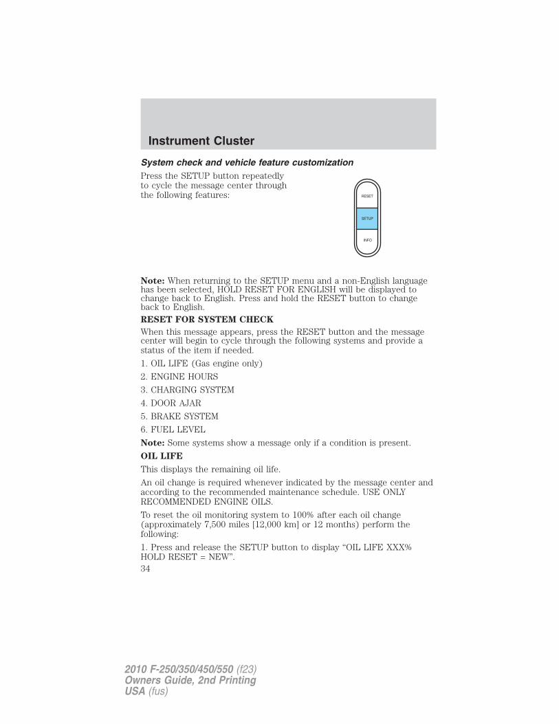
System check and vehicle feature customizationPress the SETUP button repeatedlyto cycle the message center throughthe following features:
Note: When returning to the SETUP menu and a non-English languagehas been selected, HOLD RESET FOR ENGLISH will be displayed tochange back to English. Press and hold the RESET button to changeback to English.RESET FOR SYSTEM CHECK
When this message appears, press the RESET button and the messagecenter will begin to cycle through the following systems and provide astatus of the item if needed.
1. OIL LIFE (Gas engine only)
2. ENGINE HOURS
3. CHARGING SYSTEM
4. DOOR AJAR
5. BRAKE SYSTEM
6. FUEL LEVEL
Note: Some systems show a message only if a condition is present.
OIL LIFE
This displays the remaining oil life.
An oil change is required whenever indicated by the message center andaccording to the recommended maintenance schedule. USE ONLYRECOMMENDED ENGINE OILS.
To reset the oil monitoring system to 100% after each oil change(approximately 7,500 miles [12,000 km] or 12 months) perform thefollowing:
1. Press and release the SETUP button to display “OIL LIFE XXX%HOLD RESET = NEW”.
RESET
SETUP
INFO
Instrument Cluster
34
2010 F-250/350/450/550 (f23)Owners Guide, 2nd PrintingUSA (fus)
2. Press and hold the RESET button for two seconds and release to resetthe oil life to 100%.
Note: To change oil life 100% miles value from 7,500 miles (12,000 km)or 12 months to another value, proceed to Step 3.
3. Once “OIL LIFE SET TO XXX%” is displayed, release and press theRESET button to change the Oil Life Start Value. Each release and presswill reduce the value by 10%.
Note: Oil life start value of 100% equals 7,500 miles (12,000 km) or12 months. For example, setting oil life start value to 60% sets the oillife start value to 4,500 miles (7,200 km) and 219 days.
UNITS
Displays the current units English or Metric.
Press the RESET button to change from English to Metric.
AUTOLAMP (SEC)
This feature keeps your headlights on for up to three minutes after theignition is switched off.
Press the RESET control to select the new Autolamp delay values of 0,10, 20, 30, 60, 90, 120 or 180 seconds.
AUTOLOCK
This feature automatically locks all vehicle doors when the vehicle isshifted into any gear, putting the vehicle in motion.
Press the RESET control to turn autolock on or off.
AUTOUNLOCK
This feature automatically unlocks all vehicle doors when the driver’sdoor is opened within 10 minutes of the ignition being turned off.
Press RESET to turn it off or on.
ZONE <XX> RESET = CHANGE
The compass heading is displayed as one of N, NE, E, SE, S, SW, W andNW in the message center display.
The compass reading may be affected when you drive near largebuildings, bridges, power lines and powerful broadcast antenna. Magneticor metallic objects placed in, on or near the vehicle may also affectcompass accuracy.
Usually, when something affects the compass readings, the compass willcorrect itself after a few days of operating your vehicle in normal
Instrument Cluster
35
2010 F-250/350/450/550 (f23)Owners Guide, 2nd PrintingUSA (fus)
conditions. If the compass still appears to be inaccurate, a manualcalibration may be necessary. Refer to Compass zone/calibrationadjustment.
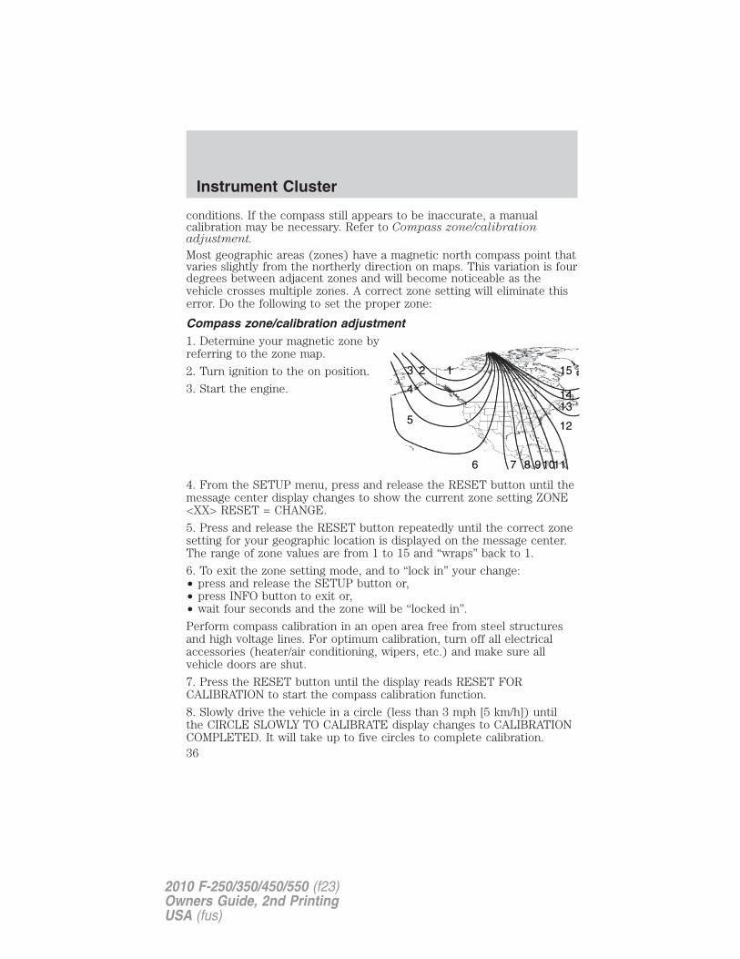
Most geographic areas (zones) have a magnetic north compass point thatvaries slightly from the northerly direction on maps. This variation is fourdegrees between adjacent zones and will become noticeable as thevehicle crosses multiple zones. A correct zone setting will eliminate thiserror. Do the following to set the proper zone:
Compass zone/calibration adjustment1. Determine your magnetic zone byreferring to the zone map.
2. Turn ignition to the on position.
3. Start the engine.
4. From the SETUP menu, press and release the RESET button until themessage center display changes to show the current zone setting ZONE<XX> RESET = CHANGE.
5. Press and release the RESET button repeatedly until the correct zonesetting for your geographic location is displayed on the message center.The range of zone values are from 1 to 15 and “wraps” back to 1.
6. To exit the zone setting mode, and to “lock in” your change:• press and release the SETUP button or,• press INFO button to exit or,• wait four seconds and the zone will be “locked in”.
Perform compass calibration in an open area free from steel structuresand high voltage lines. For optimum calibration, turn off all electricalaccessories (heater/air conditioning, wipers, etc.) and make sure allvehicle doors are shut.
7. Press the RESET button until the display reads RESET FORCALIBRATION to start the compass calibration function.
8. Slowly drive the vehicle in a circle (less than 3 mph [5 km/h]) untilthe CIRCLE SLOWLY TO CALIBRATE display changes to CALIBRATIONCOMPLETED. It will take up to five circles to complete calibration.
123
4
5
6 7 8 91011
12
1314
15
Instrument Cluster
36
2010 F-250/350/450/550 (f23)Owners Guide, 2nd PrintingUSA (fus)
9. The compass is now calibrated.Note: If the RESET button is pressed or three minutes has expired, thedisplay will go back to the INFO menu and will show CAL instead of thecompass heading until the compass is calibrated.PARK AID (if equipped)
This feature sounds a warning tone to warn the driver of obstacles nearthe rear bumper, and functions only when R (Reverse) gear is selected.Press and hold the SELECT/RESET stem to turn this feature on or off.(You can also choose to turn this feature on/off when the vehicle isplaced in reverse.)Press the SELECT/RESET stem for the next setup menu item or wait formore than four seconds to return to the info menu.LANGUAGE = ENGLISH / SPANISH / FRENCH
Allows you to choose which language the message center will display in.Selectable languages are English, Spanish, or French.Waiting four seconds or pressing the RESET button cycles the messagecenter through each of the language choices.Press and hold the RESET button for two seconds to set the languagechoice.
System warningsSystem warnings alert you to possible problems or malfunctions in yourvehicle’s operating systems.In the event of a multiple warning situation, the message center willcycle the display to show all warnings by displaying each one for fourseconds.
The message center will display the last selected feature if there are nomore warning messages.
Types of messages and warnings:
• Some messages will appear briefly to inform you of something youmay need to take action on or be informed of.
• Some messages will appear once and then again when the vehicle isrestarted.
• Some messages will reappear after clearing or being reset if a problemor condition is still present and needs your attention.
• Some messages can be acknowledged and reset by pressing RESET.This allows you to use the full message center functionality by clearingthe message.
Instrument Cluster
37
2010 F-250/350/450/550 (f23)Owners Guide, 2nd PrintingUSA (fus)
PARK BRAKE ENGAGED — Displayed when the parking brake isapplied (or not fully released).CHECK BRAKE SYSTEM — Displayed when a fault has been detectedby the ABS module.DRIVER DOOR AJAR — Displayed when the driver’s door is notcompletely closed.PASSENGER DOOR AJAR — Displayed when the passenger’s door isnot completely closed.REAR LEFT DOOR AJAR — Displayed when the rear left door is notcompletely closed.REAR RIGHT DOOR AJAR — Displayed when the rear right door isnot completely closed.XXX MILES TO E FUEL LEVEL LOW — Displayed as an earlyreminder of a low fuel condition.CHECK PARK AID (if equipped) — Displayed when the transmissionis in R (Reverse) and the reverse sensing system (park aid) is disabled.TO STOP ALARM START VEHICLE (if equipped) — Displayedwhen the perimeter alarm system is armed and the vehicle is enteredusing the key on the driver’s side door. In order to prevent the perimeteralarm system from triggering, the ignition must be turned to start or onbefore the 12–second chime expires. See Perimeter alarm system in theLocks and Security chapter.
WIRING FAULT ON TRAILER (if equipped) — Displayed andaccompanied by a single chime if there are certain faults in the vehiclewiring and trailer wiring/brake system. Refer to Trailer towing in theTires, Wheels and Loading chapter for more information.
TRAILER BRAKE MODULE FAULT (if equipped) — Displayed andaccompanied by a single chime in response to faults sensed by the TBC.Refer to Trailer towing in the Tires, Wheels and Loading chapter formore information.
TRAILER CONNECTED (if equipped) — Displayed when a correcttrailer connection (a trailer with electric trailer brakes) is sensed duringa given ignition cycle. Refer to Trailer towing in the Tires, Wheels andLoading chapter for more information.
TRAILER DISCONNECTED (if equipped) — Displayed andaccompanied by a single chime when a trailer connection becomesdisconnected, either intentionally or unintentionally, and has been sensedduring a given ignition cycle. Refer to Trailer towing in the Tires,Wheels and Loading chapter for more information.
Instrument Cluster
38
2010 F-250/350/450/550 (f23)Owners Guide, 2nd PrintingUSA (fus)
BRAKE FLUID LEVEL LOW — Indicates the brake fluid level is lowand the brake system should be inspected immediately. Refer to Brakefluid in the Maintenance and Specifications chapter.
LOW TIRE PRESSURE (if equipped) — Displayed when one or moretires on your vehicle have low tire pressure. Refer to Inflating yourtires in the Tires, Wheels and Loading chapter.
TIRE PRESSURE MONITOR FAULT (if equipped) — Displayedwhen the Tire Pressure Monitoring System is malfunctioning. If thewarning stays on or continues to come on, contact your authorizeddealer as soon as possible.
TIRE PRESSURE SENSOR FAULT (if equipped) — Displayed whena tire pressure sensor is malfunctioning, or your spare tire is in use. Formore information on how the system operates under these conditions,refer to Understanding Your Tire Pressure Monitoring System(TPMS) in the Tires, Wheels and Loading chapter. If the warning stayson or continues to come on, contact your authorized dealer as soon aspossible.
ENGINE WARMING PLEASE WAIT XX (Diesel engine only) —Displayed in extremely cold weather, typically below –15°F (–26°C), ifthe engine block heater is not utilized. The engine will not respond toaccelerator pedal movement for 30 seconds; this is done so the engine oilcan be properly circulated to avoid engine damage from lack oflubrication. A timer will begin a countdown from 30 seconds. Once thecounter has reached 0 (zero) seconds, OK TO DRIVE will be displayedand the engine will respond to accelerator pedal movement. Refer toyour Power Stroke 6.0 and 6.4 Liter Direct Injection Turbo DieselOwner’s Guide Supplement for more information.
OK TO DRIVE (Diesel engine only) — Displayed when the timecounter has reached 0 (zero) and the engine is sufficiently warm enoughto drive in extremely cold weather (refer to the engine warming pleasewait message description mentioned previously). Refer to your PowerStroke 6.0 and 6.4 Liter Direct Injection Turbo Diesel Owner’s GuideSupplement for more information.
DRAIN WATER SEPARATOR (Diesel engine only) — Displayedwhen the water separator has reached a predetermined capacity andneeds to be drained. Refer to your Power Stroke 6.0 and 6.4 LiterDirect Injection Turbo Diesel Owner’s Guide Supplement for moreinformation.
Instrument Cluster
39
2010 F-250/350/450/550 (f23)Owners Guide, 2nd PrintingUSA (fus)
ENGINE TURNS OFF IN XX (Diesel engine only) — Displayedwhen the vehicle is in the final 30 seconds of a countdown to where theengine will intentionally be turned off by the PCM. The diesel engineshutdown is a (regulatory) requirement which may be required of aparticular diesel vehicle for sale in states requiring this feature. Refer toyour Power Stroke 6.0 and 6.4 Liter Direct Injection Turbo DieselOwner’s Guide Supplement for more information.ENGINE TURNED OFF (Diesel engine only) — Displayed after the30 second countdown. Refer to your Power Stroke 6.0 and 6.4 LiterDirect Injection Turbo Diesel Owner’s Guide Supplement for moreinformation.DRIVE TO CLEAN EXHAUST FILTER (Diesel engine only) —Displayed when the Diesel Particulate Filter (DPF) is full of particles(exhaust soot) and the vehicle is not being operated in a manner toallow normal cleaning. This message will stay on until the exhaust filtercleaning has begun, at which time the CLEANING EXHAUST FILTERmessage will be displayed. It is recommended the vehicle operator drivethe vehicle above 30 mph (48 km/h) until the CLEANING EXHAUSTFILTER message turns off. This message is NORMAL. Refer to yourPower Stroke 6.0 and 6.4 Liter Direct Injection Turbo Diesel Owner’sGuide Supplement for more information.Note: If this message is ignored, your vehicle will continue to fill theDiesel Particulate Filter (DPF) with particles (exhaust soot). If cleaningis not permitted, the light will illuminate and engine power may belimited. If the vehicle is still not operated in a manner to allow cleaning,the service engine soon light will illuminate and engine power willbe further limited. Dealer service will then be required to restore yourvehicle to full-power operation.
Note: Diesel Particulate Filter (DPF) regeneration will not initiate at idleor in Power-Take-Off (PTO) mode. When DRIVE TO CLEAN EXHAUSTFILTER is displayed in the message center, PTO and/or StationaryElevated Idle Control (SEIC) must be disengaged/inactive in order toproperly clean the DPF. The vehicle must be driven until the CLEANINGEXHAUST FILTER message turns off.
CLEANING EXHAUST FILTER (Diesel engine only) — Displayedwhen the vehicle has entered the cleaning mode. Various engine actionswill raise the exhaust temperature in the Diesel Particulate Filter (DPF)system to burn off the particles (exhaust soot). After the particles areburned off, the exhaust temperature will fall back to normal levels. Thismessage is NORMAL. Refer to your Power Stroke 6.0 and 6.4 LiterDirect Injection Turbo Diesel Owner’s Guide Supplement for moreinformation.
Instrument Cluster
40
2010 F-250/350/450/550 (f23)Owners Guide, 2nd PrintingUSA (fus)
WARNING: When the CLEANING EXHAUST FILTER messageappears in the message center, do not park near flammable
materials, vapors or structures until filter cleaning is complete.
EXHAUST FILTER DRIVE COMPLETE (Diesel engine only) —Displayed when the Diesel Particulate Filter (DPF) has been adequatelycleaned after the DRIVE TO CLEAN EXHAUST FILTER followed byCLEANING EXHAUST FILTER messages have been displayed. Thismessage is NORMAL. Refer to your Power Stroke 6.0 and 6.4 LiterDirect Injection Turbo Diesel Owner’s Guide Supplement for moreinformation.
STOP SAFELY NOW (Diesel engine only) — Displayed and a chimesounds when the vehicle exhaust system temperature exceeds intendedoperating range. If this warning occurs, engine power is reduced and theengine will shut down when the vehicle speed is below 3 mph (5 km/h).Stop the vehicle as soon as safely possible and contact yourauthorized dealer. Depending on the severity of the over-temperaturecondition, the vehicle may not restart after cycling the ignition off. If thevehicle restarts, there may be limited power. If the exhaustover-temperature condition reoccurs, the message center will displaySTOP SAFELY NOW, the chime will sound, and engine power will bereduced again and shut down below 3 mph (5 km/h). Refer to yourPower Stroke 6.0 and 6.4 Liter Direct Injection Turbo Diesel Owner’sGuide Supplement for more information.
ENGINE OIL CHANGE SOON (Gas engine only) — Displayed whenthe engine oil life remaining is 5% or less.
OIL CHANGE REQUIRED (Gas engine only) — Displayed when theoil life left reaches 0%. OIL LIFE OK displays after you have changed theoil.
Instrument Cluster
41
2010 F-250/350/450/550 (f23)Owners Guide, 2nd PrintingUSA (fus)
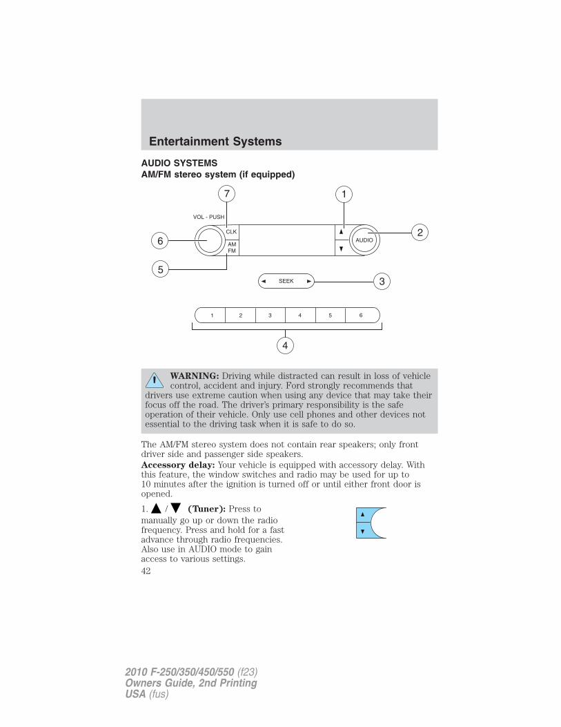
AUDIO SYSTEMSAM/FM stereo system (if equipped)
WARNING: Driving while distracted can result in loss of vehiclecontrol, accident and injury. Ford strongly recommends that
drivers use extreme caution when using any device that may take theirfocus off the road. The driver’s primary responsibility is the safeoperation of their vehicle. Only use cell phones and other devices notessential to the driving task when it is safe to do so.
The AM/FM stereo system does not contain rear speakers; only frontdriver side and passenger side speakers.Accessory delay: Your vehicle is equipped with accessory delay. Withthis feature, the window switches and radio may be used for up to10 minutes after the ignition is turned off or until either front door isopened.
1. / (Tuner): Press tomanually go up or down the radiofrequency. Press and hold for a fastadvance through radio frequencies.Also use in AUDIO mode to gainaccess to various settings.
Entertainment Systems
42
2010 F-250/350/450/550 (f23)Owners Guide, 2nd PrintingUSA (fus)
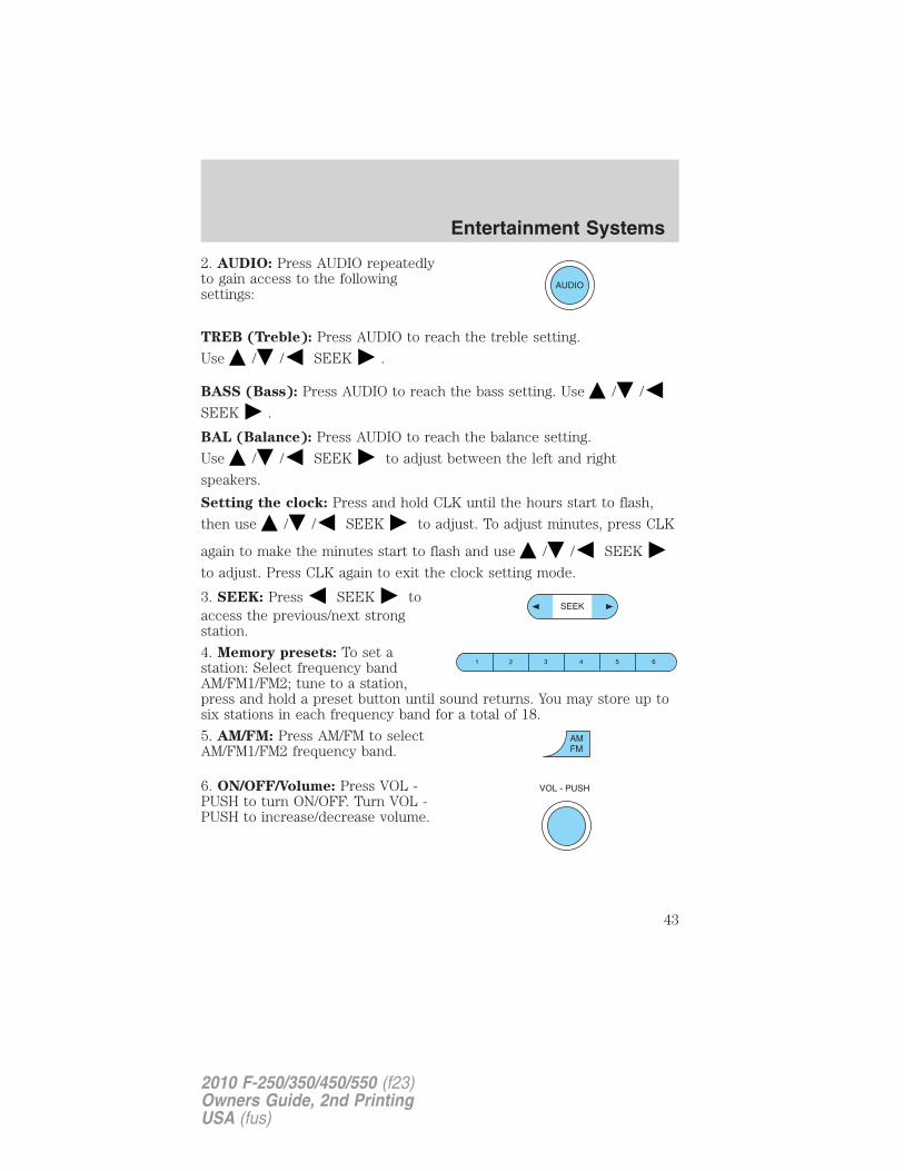
2. AUDIO: Press AUDIO repeatedlyto gain access to the followingsettings:
TREB (Treble): Press AUDIO to reach the treble setting.
Use / / SEEK .
BASS (Bass): Press AUDIO to reach the bass setting. Use / /
SEEK .
BAL (Balance): Press AUDIO to reach the balance setting.
Use / / SEEK to adjust between the left and right
speakers.
Setting the clock: Press and hold CLK until the hours start to flash,
then use / / SEEK to adjust. To adjust minutes, press CLK
again to make the minutes start to flash and use / / SEEK
to adjust. Press CLK again to exit the clock setting mode.
3. SEEK: Press SEEK toaccess the previous/next strongstation.
4. Memory presets: To set astation: Select frequency bandAM/FM1/FM2; tune to a station,press and hold a preset button until sound returns. You may store up tosix stations in each frequency band for a total of 18.
5. AM/FM: Press AM/FM to selectAM/FM1/FM2 frequency band.
6. ON/OFF/Volume: Press VOL -PUSH to turn ON/OFF. Turn VOL -PUSH to increase/decrease volume.
Entertainment Systems
43
2010 F-250/350/450/550 (f23)Owners Guide, 2nd PrintingUSA (fus)
7. CLK (Clock): Press CLK totoggle between the clock and radiofrequency.
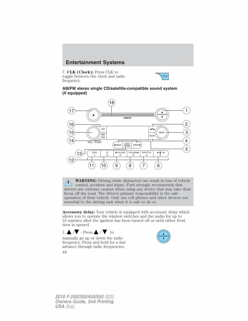
AM/FM stereo single CD/satellite-compatible sound system(if equipped)
WARNING: Driving while distracted can result in loss of vehiclecontrol, accident and injury. Ford strongly recommends that
drivers use extreme caution when using any device that may take theirfocus off the road. The driver’s primary responsibility is the safeoperation of their vehicle. Only use cell phones and other devices notessential to the driving task when it is safe to do so.
Accessory delay: Your vehicle is equipped with accessory delay whichallows you to operate the window switches and the audio for up to10 minutes after the ignition has been turned off or until either frontdoor is opened.
1. / : Press / to
manually go up or down the radiofrequency. Press and hold for a fastadvance through radio frequencies.
Entertainment Systems
44
2010 F-250/350/450/550 (f23)Owners Guide, 2nd PrintingUSA (fus)
In satellite radio mode (if equipped), press / to tune to thenext/previous channel.Satellite radio is available only with a valid SIRIUS� radiosubscription. Check with your authorized dealer for availability.
2. (Phone): If your vehicle isequipped with SYNC�, press toaccess SYNC PHONE features. Forfurther information, please refer to your SYNC� supplement.If your vehicle is not equipped with SYNC�, the display will read NOPHONE.
3. MENU: Press MENU repeatedlyto access to the following settings:
Setting the clock: Press MENU until SET HOUR or SET MINUTES isdisplayed. Use / / SEEK, SEEK to adjust thehours/minutes.SATELLITE RADIO MENU (if equipped): Press MENU when satelliteradio mode is active to access. Press OK to enter into the satellite radiomenu. Press / to cycle through the following options:
• CATEGORY: Press OK to enter category mode. Press / toscroll through the list of available SIRIUS� channel Categories (Pop,Rock, News, etc.) Press OK when the desired category appears in thedisplay. After a category is selected, press SEEK to search for thatspecific category of channels only (i.e. ROCK). You may also selectCATEGORY ALL to seek all available SIRIUS� categories and channels.Press OK to close and return to the main menu.
• SAVE SONG: Press OK to save the currently playing song title in thesystem’s memory. (If you try to save something other than a song,CANT SAVE will appear in the display.) When the chosen song isplaying on any satellite radio channel, the system will alert you withan audible prompt. Press OK while SONG ALERT is in the display andthe system will take you to the channel playing the desired song. Youcan save up to 20 song titles. If you attempt to save a song when thesystem is full, the display will read REPLACE SONG? Press OK toaccess the saved songs and press / to cycle through the savedsongs. When the song appears in the display that you would like toreplace, press OK. SONG REPLACED will appear in the display.
Entertainment Systems
45
2010 F-250/350/450/550 (f23)Owners Guide, 2nd PrintingUSA (fus)
• DELETE SONG: Press OK to delete a song title from the system’smemory. Press / to cycle through the saved songs. When thesong title appears in the display that you would like to delete, pressOK. The song will appear in the display for confirmation. Press OKagain and the display will read SONG DELETED. If you do not wantto delete the currently listed song, press / to select eitherRETURN or CANCEL.Note: If there are no songs presently saved, the display will read NOSONGS.
• DELETE ALL SONGS: Press OK to delete all songs from thesystem’s memory. The display will read ARE YOU SURE? Press OK toconfirm deletion of all saved songs and the display will read ALLDELETED.Note: If there are no songs presently saved, the display will read NOSONGS.
• ENABLE ALERTS / DISABLE ALERTS: Press OK to enable/disablethe satellite alert status which alerts you when your selected songs areplaying on a satellite radio channel. (The system default is disabled.)SONG ALERTS ENABLED/DISABLED will appear in the display. Themenu listing will display the opposite state. For example, if you havechosen to enable the song alerts, the menu listing will read DISABLEas the alerts are currently on, so your other option is to turn them off.
Satellite radio is available only with a valid SIRIUS� radiosubscription. Check with your authorized dealer for availability.
AUTOSET: Press MENU until the display reads AUTOSET. Autosetallows you to set the strongest local radio stations without losing youroriginal manually set preset stations for AM/FM1/FM2. Use / /SEEK, SEEK to turn on/off.When the six strongest stations are filled, the station stored in preset 1will begin playing. If there are less than six strong stations, the systemwill store the last one in the remaining presets.
BASS: Press MENU to reach the bass setting. Use / / SEEK,
SEEK to adjust.
TREB (Treble): Press MENU to reach the treble setting.
Use / / SEEK, SEEK to adjust.
BAL (Balance): Press MENU to reach the balance setting.
Use / / SEEK, SEEK to adjust the audio between the left
(L) and right (R) speakers.
Entertainment Systems
46
2010 F-250/350/450/550 (f23)Owners Guide, 2nd PrintingUSA (fus)
FADE: Press MENU to reach the fade setting. Use / / SEEK,
SEEK to adjust the audio between the back (B) and front (F)speakers.
SPEEDVOL (Speed sensitive volume, if equipped): Press MENU toreach the SPEEDVOL setting. Radio volume automatically gets louderwith increasing vehicle speed to compensate for road and wind noise.
Use / / SEEK, SEEK to adjust.
The default setting is off; increasing your vehicle speed will not changethe volume level.
Adjust 1–7: Increasing this setting from 1 (lowest setting) to 7 (highestsetting) allows the radio volume to automatically change slightly withvehicle speed to compensate for road and wind noise.
Recommended level is 1–3; SPEED OFF turns the feature off and level 7is the maximum setting.
Track/Folder mode: Available only on MP3 discs in CD mode. In Trackmode, pressing SEEK, SEEK will scroll through all tracks on thediscIn Folder mode, pressing SEEK, SEEK will scroll only throughtracks within the selected folder.Press FOLDER, FOLDER to access the previous/next folder (ifavailable).
COMPRESS (Compression): Available only in CD/MP3 mode. PressMENU until COMPRESS ON/OFF appears in the display.
Use / / SEEK, SEEK to toggle ON/OFF. When COMPRESS
is ON, the system will bring the soft and loud CD passages together for amore consistent listening level.
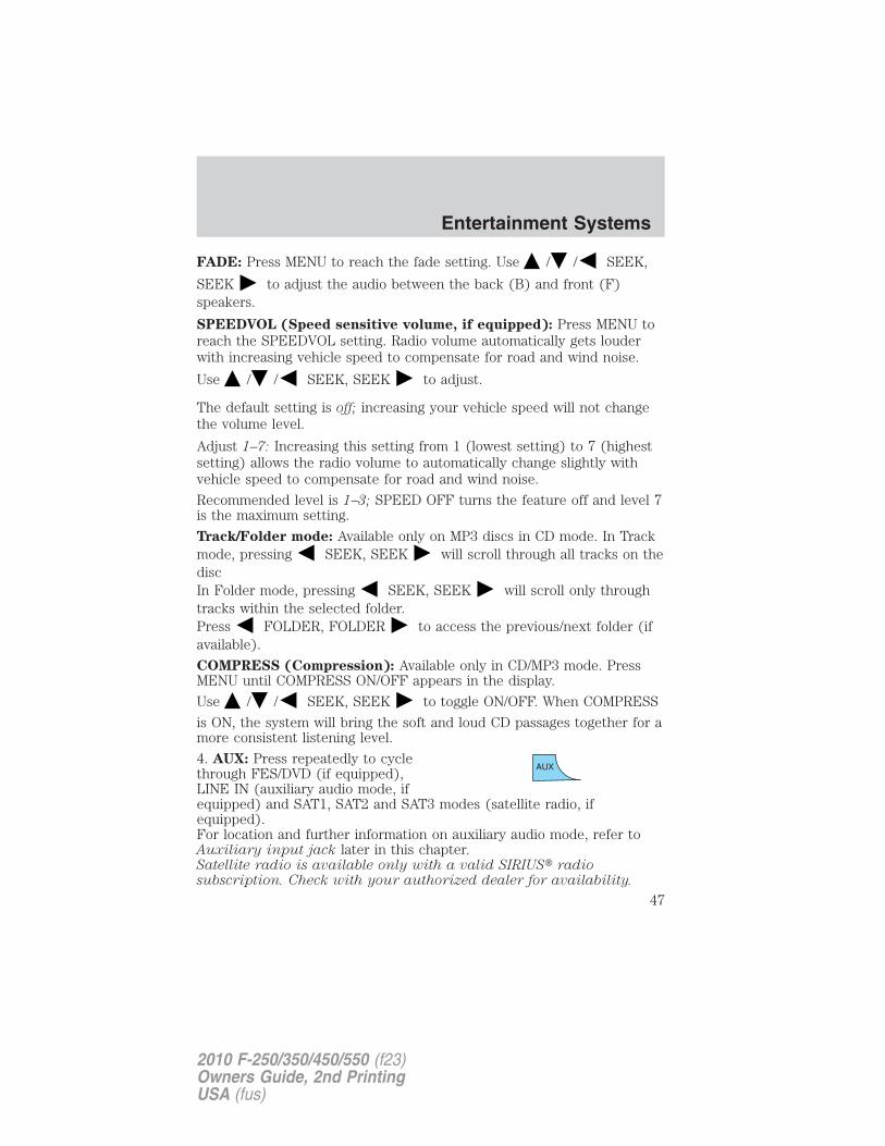
4. AUX: Press repeatedly to cyclethrough FES/DVD (if equipped),LINE IN (auxiliary audio mode, ifequipped) and SAT1, SAT2 and SAT3 modes (satellite radio, ifequipped).For location and further information on auxiliary audio mode, refer toAuxiliary input jack later in this chapter.Satellite radio is available only with a valid SIRIUS� radiosubscription. Check with your authorized dealer for availability.
Entertainment Systems
47
2010 F-250/350/450/550 (f23)Owners Guide, 2nd PrintingUSA (fus)
5. SEEK: In radio mode,
press / to access theprevious/next strong station.
In CD/MP3 mode, press /to access the previous/next CD/MP3 track.
In satellite radio mode (if equipped), press SEEK, SEEK toseek to the previous/next channel. If a specific category is selected,(Jazz, Rock, News, etc.), press SEEK, SEEK to seek to the
previous/next channel in the selected category. Press and holdSEEK, SEEK to fast seek through the previous /next channels.
In TEXT MODE, press SEEK, SEEK to view theprevious/additional display text.In CATEGORY MODE, press SEEK, SEEK to select a category.Satellite radio is available only with a valid SIRIUS� radio
subscription. Check with your authorized dealer for availability.
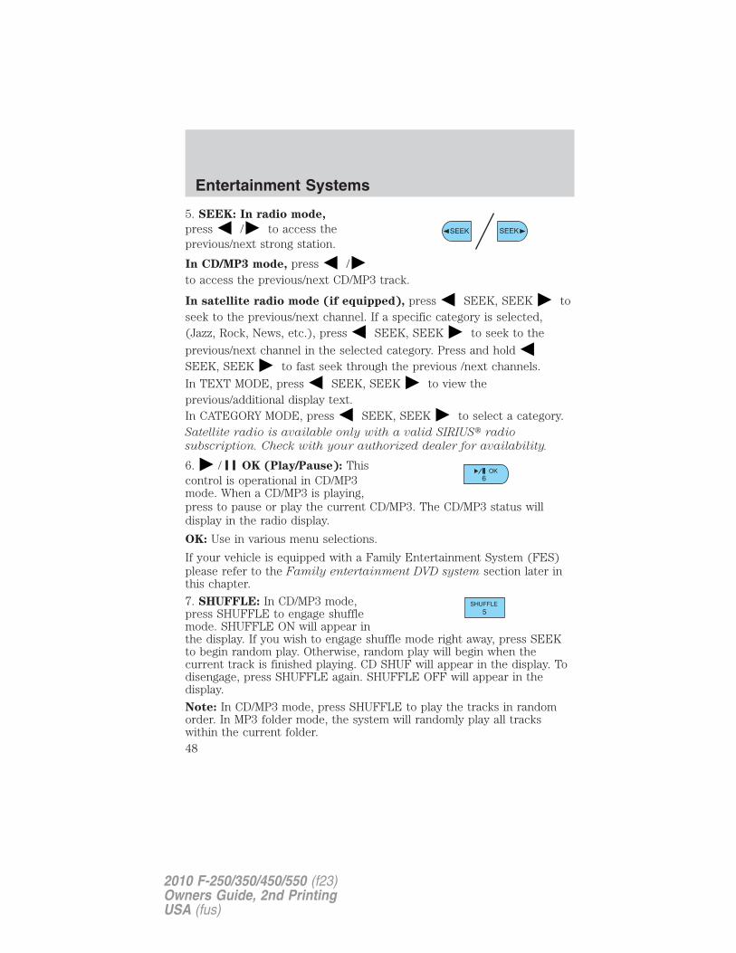
6. / OK (Play/Pause): Thiscontrol is operational in CD/MP3mode. When a CD/MP3 is playing,press to pause or play the current CD/MP3. The CD/MP3 status willdisplay in the radio display.
OK: Use in various menu selections.
If your vehicle is equipped with a Family Entertainment System (FES)please refer to the Family entertainment DVD system section later inthis chapter.
7. SHUFFLE: In CD/MP3 mode,press SHUFFLE to engage shufflemode. SHUFFLE ON will appear inthe display. If you wish to engage shuffle mode right away, press SEEKto begin random play. Otherwise, random play will begin when thecurrent track is finished playing. CD SHUF will appear in the display. Todisengage, press SHUFFLE again. SHUFFLE OFF will appear in thedisplay.
Note: In CD/MP3 mode, press SHUFFLE to play the tracks in randomorder. In MP3 folder mode, the system will randomly play all trackswithin the current folder.
Entertainment Systems
48
2010 F-250/350/450/550 (f23)Owners Guide, 2nd PrintingUSA (fus)
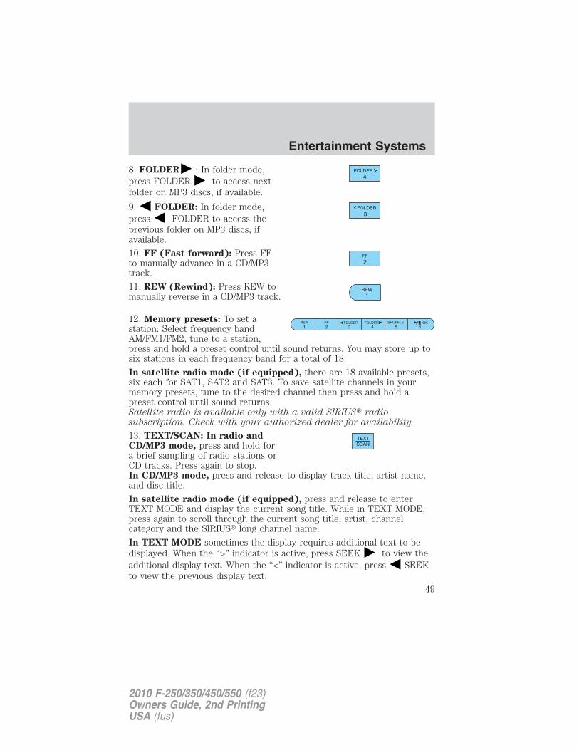
8. FOLDER : In folder mode,press FOLDER to access nextfolder on MP3 discs, if available.
9. FOLDER: In folder mode,press FOLDER to access theprevious folder on MP3 discs, ifavailable.
10. FF (Fast forward): Press FFto manually advance in a CD/MP3track.
11. REW (Rewind): Press REW tomanually reverse in a CD/MP3 track.
12. Memory presets: To set astation: Select frequency bandAM/FM1/FM2; tune to a station,press and hold a preset control until sound returns. You may store up tosix stations in each frequency band for a total of 18.
In satellite radio mode (if equipped), there are 18 available presets,six each for SAT1, SAT2 and SAT3. To save satellite channels in yourmemory presets, tune to the desired channel then press and hold apreset control until sound returns.Satellite radio is available only with a valid SIRIUS� radiosubscription. Check with your authorized dealer for availability.
13. TEXT/SCAN: In radio andCD/MP3 mode, press and hold fora brief sampling of radio stations orCD tracks. Press again to stop.In CD/MP3 mode, press and release to display track title, artist name,and disc title.
In satellite radio mode (if equipped), press and release to enterTEXT MODE and display the current song title. While in TEXT MODE,press again to scroll through the current song title, artist, channelcategory and the SIRIUS� long channel name.
In TEXT MODE sometimes the display requires additional text to bedisplayed. When the “>” indicator is active, press SEEK to view theadditional display text. When the “<” indicator is active, press SEEKto view the previous display text.
Entertainment Systems
49
2010 F-250/350/450/550 (f23)Owners Guide, 2nd PrintingUSA (fus)
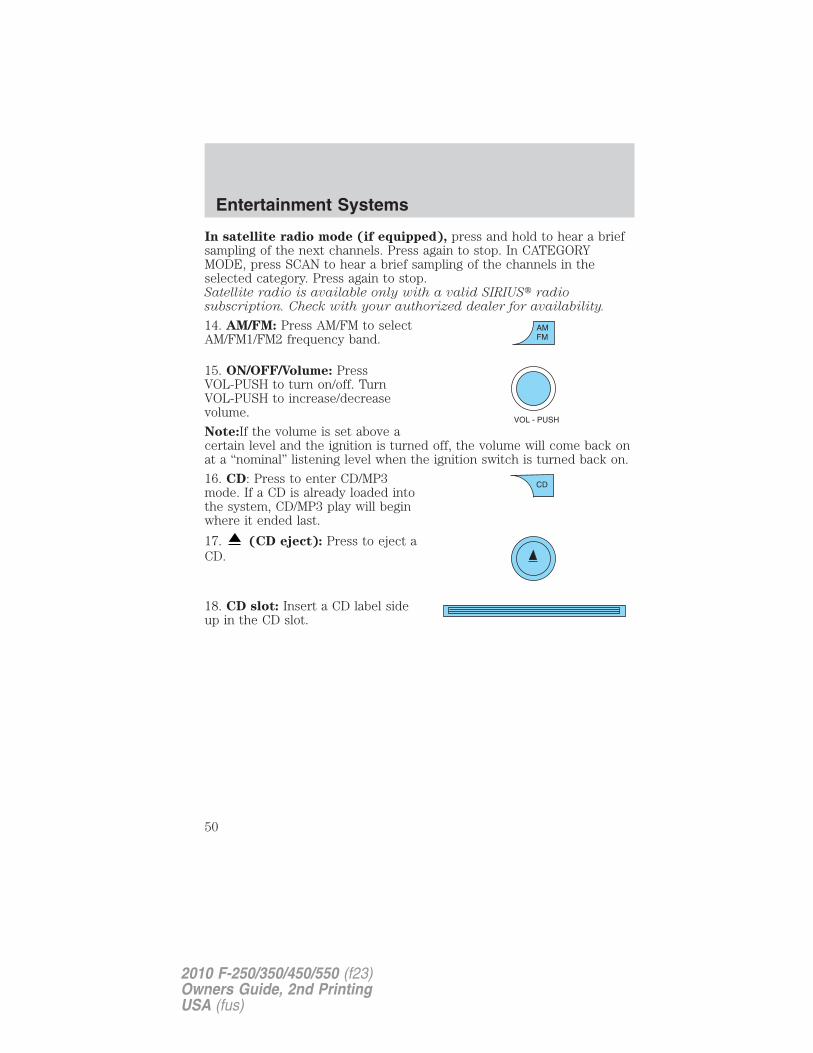
In satellite radio mode (if equipped), press and hold to hear a briefsampling of the next channels. Press again to stop. In CATEGORYMODE, press SCAN to hear a brief sampling of the channels in theselected category. Press again to stop.Satellite radio is available only with a valid SIRIUS� radiosubscription. Check with your authorized dealer for availability.
14. AM/FM: Press AM/FM to selectAM/FM1/FM2 frequency band.
15. ON/OFF/Volume: PressVOL-PUSH to turn on/off. TurnVOL-PUSH to increase/decreasevolume.
Note:If the volume is set above acertain level and the ignition is turned off, the volume will come back onat a “nominal” listening level when the ignition switch is turned back on.
16. CD: Press to enter CD/MP3mode. If a CD is already loaded intothe system, CD/MP3 play will beginwhere it ended last.
17. (CD eject): Press to eject aCD.
18. CD slot: Insert a CD label sideup in the CD slot.
Entertainment Systems
50
2010 F-250/350/450/550 (f23)Owners Guide, 2nd PrintingUSA (fus)
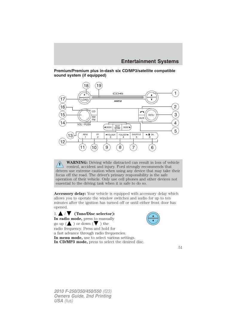
Premium/Premium plus in-dash six CD/MP3/satellite compatiblesound system (if equipped)
WARNING: Driving while distracted can result in loss of vehiclecontrol, accident and injury. Ford strongly recommends that
drivers use extreme caution when using any device that may take theirfocus off the road. The driver’s primary responsibility is the safeoperation of their vehicle. Only use cell phones and other devices notessential to the driving task when it is safe to do so.
Accessory delay: Your vehicle is equipped with accessory delay whichallows you to operate the window switches and audio for up to tenminutes after the ignition has turned off or until either front door hasopened.
1. / (Tune/Disc selector):
In radio mode, press to manuallygo up ( ) or down ( ) theradio frequency. Press and hold fora fast advance through radio frequencies.In menu mode, use to select various settings.In CD/MP3 mode, press to select the desired disc.
Entertainment Systems
51
2010 F-250/350/450/550 (f23)Owners Guide, 2nd PrintingUSA (fus)
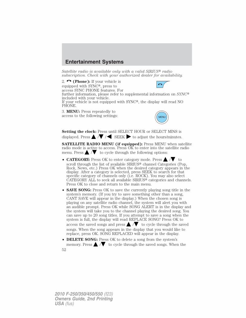
Satellite radio is available only with a valid SIRIUS� radiosubscription. Check with your authorized dealer for availability.
2. (Phone): If your vehicle isequipped with SYNC�, press toaccess SYNC PHONE features. Forfurther information, please refer to supplemental information on SYNC�included with your vehicle.If your vehicle is not equipped with SYNC�, the display will read NOPHONE.
3. MENU: Press repeatedly toaccess to the following settings:
Setting the clock: Press until SELECT HOUR or SELECT MINS isdisplayed. Press / / SEEK to adjust the hours/minutes.
SATELLITE RADIO MENU (if equipped): Press MENU when satelliteradio mode is active to access. Press OK to enter into the satellite radiomenu. Press / to cycle through the following options:
• CATEGORY: Press OK to enter category mode. Press / toscroll through the list of available SIRIUS� channel Categories (Pop,Rock, News, etc.) Press OK when the desired category appears in thedisplay. After a category is selected, press SEEK to search for thatspecific category of channels only (i.e. ROCK). You may also selectCATEGORY ALL to seek all available SIRIUS� categories and channels.Press OK to close and return to the main menu.
• SAVE SONG: Press OK to save the currently playing song title in thesystem’s memory. (If you try to save something other than a song,CANT SAVE will appear in the display.) When the chosen song isplaying on any satellite radio channel, the system will alert you withan audible prompt. Press OK while SONG ALERT is in the display andthe system will take you to the channel playing the desired song. Youcan save up to 20 song titles. If you attempt to save a song when thesystem is full, the display will read REPLACE SONG? Press OK toaccess the saved songs and press / to cycle through the savedsongs. When the song appears in the display that you would like toreplace, press OK. SONG REPLACED will appear in the display.
• DELETE SONG: Press OK to delete a song from the system’smemory. Press / to cycle through the saved songs. When the
Entertainment Systems
52
2010 F-250/350/450/550 (f23)Owners Guide, 2nd PrintingUSA (fus)
song appears in the display that you would like to delete, press OK.The song will appear in the display for confirmation. Press OK againand the display will read SONG DELETED. If you do not want todelete the currently listed song, press / to select eitherRETURN or CANCEL.Note: If there are no songs presently saved, the display will read NOSONGS.
• DELETE ALL SONGS: Press OK to delete all songs from thesystem’s memory. The display will read ARE YOU SURE ? Press OK toconfirm deletion of all saved songs and the display will read ALLDELETED.Note: If there are no songs presently saved, the display will read NOSONGS.
• ENABLE ALERTS / DISABLE ALERTS: Press OK to enable/disablethe satellite alert status which alerts you when your selected songs areplaying on a satellite radio channel. (The system default is disabled.)SONG ALERTS ENABLED/DISABLED will appear in the display. Themenu listing will display the opposite state. For example, if you havechosen to enable the song alerts, the menu listing will read DISABLEas the alerts are currently on, so your other option is to turn them off.
Satellite radio is available only with a valid SIRIUS� radiosubscription. Check with your authorized dealer for availability.
AUTOSET: Press MENU until the display reads AUTOSET. Autosetallows you to set the strongest local radio stations without losing youroriginal manually set preset stations for AM/FM1/FM2. Use / /SEEK, SEEK to turn on/off.When the six strongest stations are filled, the station stored in preset 1will begin playing. If there are less than six strong stations, the systemwill store the last one in the remaining presets.RBDS: Available only in FM mode. This feature allows you to searchRBDS-equipped stations for a certain category of music format:CLASSIC, COUNTRY, INFORM, JAZZ/RB, ROCK, etc.To activate, press MENU repeatedly until RBDS (ON/OFF) appears inthe display. Use / / SEEK to toggle RBDS ON/OFF. When
RBDS is OFF, you will not be able to search for RBDS equipped stationsor view the station name or type.
To search for specific RBDS music categories: When the desiredcategory appears in the display, press / to find the desired type,
then press and release SEEK, SEEK or press and hold SCAN tobegin the search.
Entertainment Systems
53
2010 F-250/350/450/550 (f23)Owners Guide, 2nd PrintingUSA (fus)
To view the station name or type: When the desired category appearsin the display, press TEXT/SCAN to toggle between displaying the stationtype (COUNTRY, ROCK, etc.) or the station name (WYCD, WXYZ, etc.).
BASS: Press MENU to reach the bass setting. Use / / SEEK,SEEK to adjust.
TREB (Treble): Press MENU to reach the treble setting.
Use / / SEEK, SEEK to adjust.
BAL (Balance): Press MENU to reach the balance setting.
Use / / SEEK, SEEK to adjust the audio between the left
(L) and right (R) speakers.
FADE: Press MENU to reach the fade setting. Use / / SEEK,
SEEK to adjust the audio between the back (B) and front (F)speakers.
ALL SEATS (Occupancy mode) (Available on Audiophile radios only):
Press MENU repeatedly to access. Press / / SEEK to
optimize sound for ALL SEATS, DRIVERS SEAT or REAR SEATS.
SPEEDVOL (Speed sensitive volume, if equipped): Press MENU toreach the SPEEDVOL setting. Radio volume automatically gets louderwith increasing vehicle speed to compensate for road and wind noise.
Use / / SEEK, SEEK to adjust.
The default setting is off; increasing your vehicle speed will not changethe volume level.
Adjust 1–7: Increasing this setting from 1 (lowest setting) to 7 (highestsetting) allows the radio volume to automatically change slightly withvehicle speed to compensate for road and wind noise.
Recommended level is1–3; SPEED OFF turns the feature off and level 7is the maximum setting.
Track/Folder Mode: Available only on MP3 discs in CD mode. In TrackMode, pressing SEEK will scroll through all tracks on the disc.
In Folder mode, pressing SEEK will scroll only through trackswithin the selected folder.Press FOLDER, FOLDER to access the previous/next folder (ifavailable).
Entertainment Systems
54
2010 F-250/350/450/550 (f23)Owners Guide, 2nd PrintingUSA (fus)
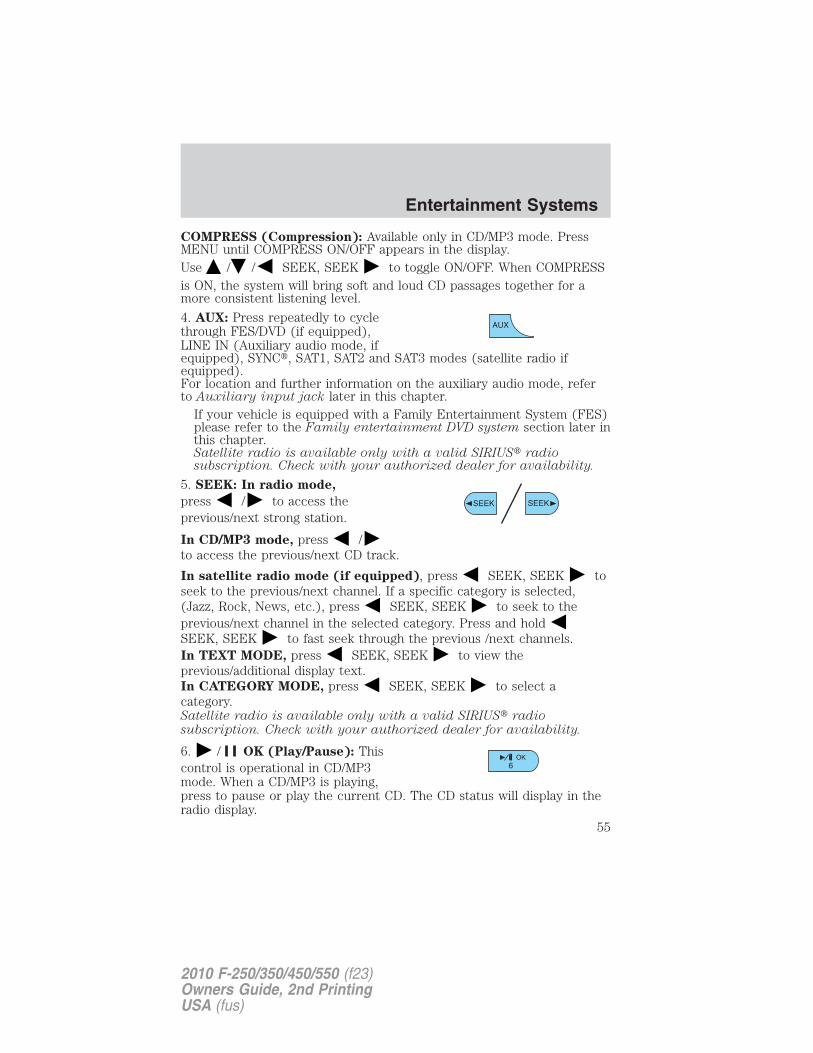
COMPRESS (Compression): Available only in CD/MP3 mode. PressMENU until COMPRESS ON/OFF appears in the display.Use / / SEEK, SEEK to toggle ON/OFF. When COMPRESSis ON, the system will bring soft and loud CD passages together for amore consistent listening level.
4. AUX: Press repeatedly to cyclethrough FES/DVD (if equipped),LINE IN (Auxiliary audio mode, ifequipped), SYNC�, SAT1, SAT2 and SAT3 modes (satellite radio ifequipped).For location and further information on the auxiliary audio mode, referto Auxiliary input jack later in this chapter.
If your vehicle is equipped with a Family Entertainment System (FES)please refer to the Family entertainment DVD system section later inthis chapter.Satellite radio is available only with a valid SIRIUS� radiosubscription. Check with your authorized dealer for availability.
5. SEEK: In radio mode,
press / to access theprevious/next strong station.
In CD/MP3 mode, press /to access the previous/next CD track.
In satellite radio mode (if equipped), press SEEK, SEEK toseek to the previous/next channel. If a specific category is selected,(Jazz, Rock, News, etc.), press SEEK, SEEK to seek to theprevious/next channel in the selected category. Press and holdSEEK, SEEK to fast seek through the previous /next channels.In TEXT MODE, press SEEK, SEEK to view theprevious/additional display text.In CATEGORY MODE, press SEEK, SEEK to select acategory.Satellite radio is available only with a valid SIRIUS� radiosubscription. Check with your authorized dealer for availability.
6. / OK (Play/Pause): Thiscontrol is operational in CD/MP3mode. When a CD/MP3 is playing,press to pause or play the current CD. The CD status will display in theradio display.
Entertainment Systems
55
2010 F-250/350/450/550 (f23)Owners Guide, 2nd PrintingUSA (fus)
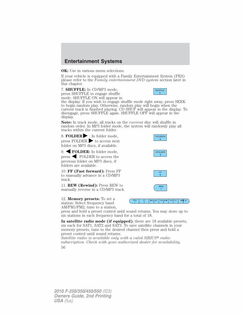
OK: Use in various menu selections.If your vehicle is equipped with a Family Entertainment System (FES)please refer to the Family entertainment DVD system section later inthis chapter.
7. SHUFFLE: In CD/MP3 mode,press SHUFFLE to engage shufflemode. SHUFFLE ON will appear inthe display. If you wish to engage shuffle mode right away, press SEEKto begin random play. Otherwise, random play will begin when thecurrent track is finished playing. CD SHUF will appear in the display. Todisengage, press SHUFFLE again. SHUFFLE OFF will appear in thedisplay.Note: In track mode, all tracks on the current disc will shuffle inrandom order. In MP3 folder mode, the system will randomly play alltracks within the current folder.
8. FOLDER : In folder mode,press FOLDER to access nextfolder on MP3 discs, if available.
9. FOLDER: In folder mode,press FOLDER to access theprevious folder on MP3 discs, iffolders are available.
10. FF (Fast forward): Press FFto manually advance in a CD/MP3track.
11. REW (Rewind): Press REW tomanually reverse in a CD/MP3 track.
12. Memory presets: To set astation: Select frequency bandAM/FM1/FM2; tune to a station,press and hold a preset control until sound returns. You may store up tosix stations in each frequency band for a total of 18.
In satellite radio mode (if equipped), there are 18 available presets,six each for SAT1, SAT2 and SAT3. To save satellite channels in yourmemory presets, tune to the desired channel then press and hold apreset control until sound returns.Satellite radio is available only with a valid SIRIUS� radiosubscription. Check with your authorized dealer for availability.
Entertainment Systems
56
2010 F-250/350/450/550 (f23)Owners Guide, 2nd PrintingUSA (fus)
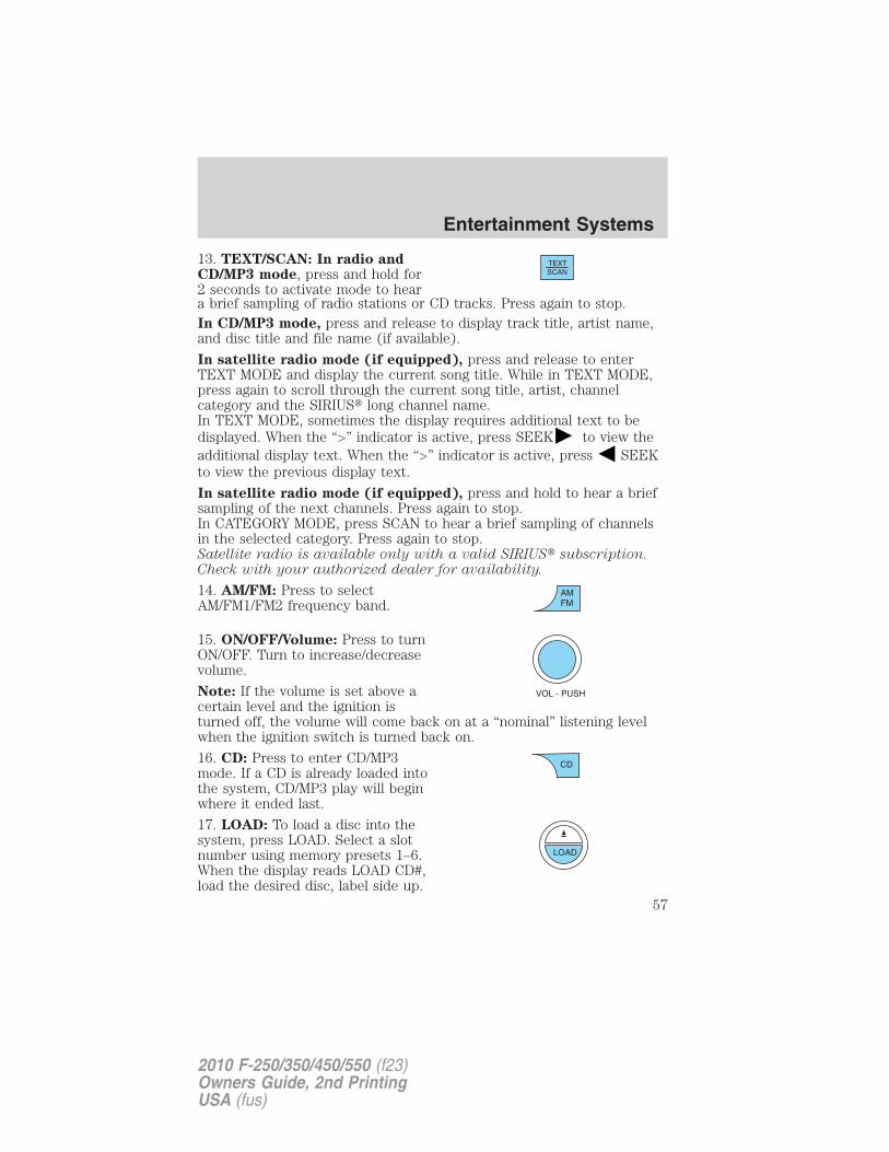
13. TEXT/SCAN: In radio andCD/MP3 mode, press and hold for2 seconds to activate mode to heara brief sampling of radio stations or CD tracks. Press again to stop.In CD/MP3 mode, press and release to display track title, artist name,and disc title and file name (if available).
In satellite radio mode (if equipped), press and release to enterTEXT MODE and display the current song title. While in TEXT MODE,press again to scroll through the current song title, artist, channelcategory and the SIRIUS� long channel name.In TEXT MODE, sometimes the display requires additional text to bedisplayed. When the “>” indicator is active, press SEEK to view theadditional display text. When the “>” indicator is active, press SEEKto view the previous display text.
In satellite radio mode (if equipped), press and hold to hear a briefsampling of the next channels. Press again to stop.In CATEGORY MODE, press SCAN to hear a brief sampling of channelsin the selected category. Press again to stop.Satellite radio is available only with a valid SIRIUS� subscription.Check with your authorized dealer for availability.
14. AM/FM: Press to selectAM/FM1/FM2 frequency band.
15. ON/OFF/Volume: Press to turnON/OFF. Turn to increase/decreasevolume.
Note: If the volume is set above acertain level and the ignition isturned off, the volume will come back on at a “nominal” listening levelwhen the ignition switch is turned back on.
16. CD: Press to enter CD/MP3mode. If a CD is already loaded intothe system, CD/MP3 play will beginwhere it ended last.
17. LOAD: To load a disc into thesystem, press LOAD. Select a slotnumber using memory presets 1–6.When the display reads LOAD CD#,load the desired disc, label side up.
Entertainment Systems
57
2010 F-250/350/450/550 (f23)Owners Guide, 2nd PrintingUSA (fus)
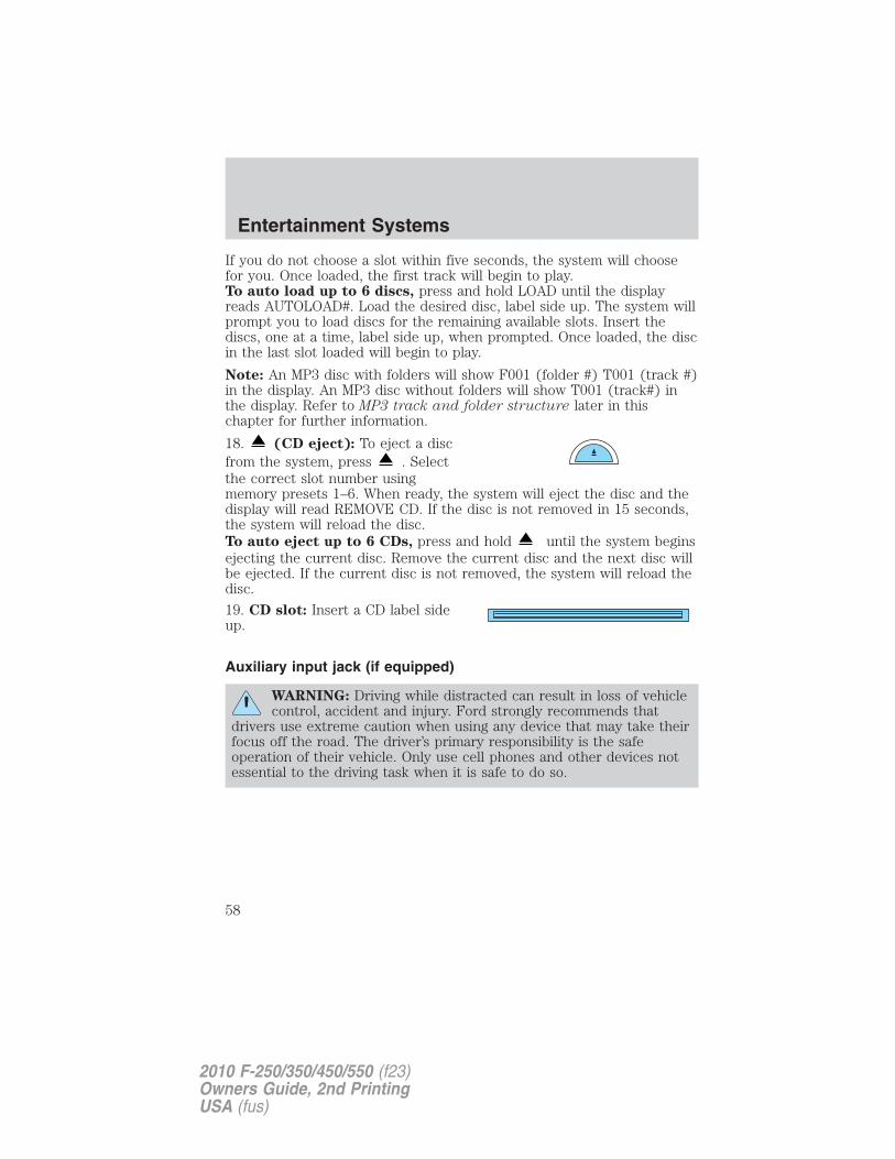
If you do not choose a slot within five seconds, the system will choosefor you. Once loaded, the first track will begin to play.To auto load up to 6 discs, press and hold LOAD until the displayreads AUTOLOAD#. Load the desired disc, label side up. The system willprompt you to load discs for the remaining available slots. Insert thediscs, one at a time, label side up, when prompted. Once loaded, the discin the last slot loaded will begin to play.
Note: An MP3 disc with folders will show F001 (folder #) T001 (track #)in the display. An MP3 disc without folders will show T001 (track#) inthe display. Refer to MP3 track and folder structure later in thischapter for further information.
18. (CD eject): To eject a discfrom the system, press . Selectthe correct slot number usingmemory presets 1–6. When ready, the system will eject the disc and thedisplay will read REMOVE CD. If the disc is not removed in 15 seconds,the system will reload the disc.To auto eject up to 6 CDs, press and hold until the system beginsejecting the current disc. Remove the current disc and the next disc willbe ejected. If the current disc is not removed, the system will reload thedisc.
19. CD slot: Insert a CD label sideup.
Auxiliary input jack (if equipped)
WARNING: Driving while distracted can result in loss of vehiclecontrol, accident and injury. Ford strongly recommends that
drivers use extreme caution when using any device that may take theirfocus off the road. The driver’s primary responsibility is the safeoperation of their vehicle. Only use cell phones and other devices notessential to the driving task when it is safe to do so.
Entertainment Systems
58
2010 F-250/350/450/550 (f23)Owners Guide, 2nd PrintingUSA (fus)
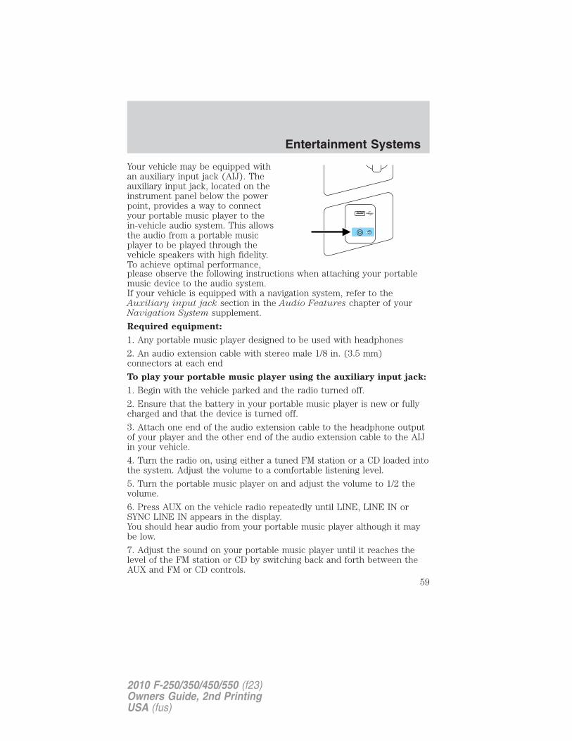
Your vehicle may be equipped withan auxiliary input jack (AIJ). Theauxiliary input jack, located on theinstrument panel below the powerpoint, provides a way to connectyour portable music player to thein-vehicle audio system. This allowsthe audio from a portable musicplayer to be played through thevehicle speakers with high fidelity.To achieve optimal performance,please observe the following instructions when attaching your portablemusic device to the audio system.If your vehicle is equipped with a navigation system, refer to theAuxiliary input jack section in the Audio Features chapter of yourNavigation System supplement.
Required equipment:
1. Any portable music player designed to be used with headphones
2. An audio extension cable with stereo male 1/8 in. (3.5 mm)connectors at each end
To play your portable music player using the auxiliary input jack:
1. Begin with the vehicle parked and the radio turned off.
2. Ensure that the battery in your portable music player is new or fullycharged and that the device is turned off.
3. Attach one end of the audio extension cable to the headphone outputof your player and the other end of the audio extension cable to the AIJin your vehicle.
4. Turn the radio on, using either a tuned FM station or a CD loaded intothe system. Adjust the volume to a comfortable listening level.
5. Turn the portable music player on and adjust the volume to 1/2 thevolume.
6. Press AUX on the vehicle radio repeatedly until LINE, LINE IN orSYNC LINE IN appears in the display.You should hear audio from your portable music player although it maybe low.
7. Adjust the sound on your portable music player until it reaches thelevel of the FM station or CD by switching back and forth between theAUX and FM or CD controls.
Entertainment Systems
59
2010 F-250/350/450/550 (f23)Owners Guide, 2nd PrintingUSA (fus)
Troubleshooting:
1. Do not connect the audio input jack to a line level output. Line leveloutputs are intended for connection to a home stereo and are notcompatible with the AIJ. The AIJ will only work correctly with devicesthat have a headphone output with a volume control.
2. Do not set the portable music player’s volume level higher than isnecessary to match the volume of the CD or FM radio in your audiosystem as this will cause distortion and will reduce sound quality. Manyportable music players have different output levels, so not all playersshould be set at the same levels. Some players will sound best at fullvolume and others will need to be set at a lower volume.
3. If the music sounds distorted at lower listening levels, turn theportable music player volume down. If the problems persist, replace orrecharge the batteries in the portable music player.
4. The portable music player must be controlled in the same mannerwhen it is used with headphones as the AIJ does not provide control(play, pause, etc.) over the attached portable music player.
5. For safety reasons, connecting or adjusting the settings on yourportable music player should not be attempted while the vehicle ismoving. Also, the portable music player should be stored in a securelocation, such as the center console or the glove box, when the vehicle isin motion. The audio extension cable must be long enough to allow theportable music player to be safely stored while the vehicle is in motion.
USB port (if equipped)
WARNING: Driving while distracted can result in loss of vehiclecontrol, accident and injury. Ford strongly recommends that
drivers use extreme caution when using any device that may take theirfocus off the road. The driver’s primary responsibility is the safeoperation of their vehicle. Only use cell phones and other devices notessential to the driving task when it is safe to do so.
Entertainment Systems
60
2010 F-250/350/450/550 (f23)Owners Guide, 2nd PrintingUSA (fus)
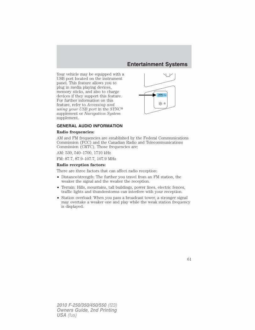
Your vehicle may be equipped with aUSB port located on the instrumentpanel. This feature allows you toplug in media playing devices,memory sticks, and also to chargedevices if they support this feature.For further information on thisfeature, refer to Accessing andusing your USB port in the SYNC�supplement or Navigation Systemsupplement.
GENERAL AUDIO INFORMATIONRadio frequencies:
AM and FM frequencies are established by the Federal CommunicationsCommission (FCC) and the Canadian Radio and TelecommunicationsCommission (CRTC). Those frequencies are:
AM: 530, 540–1700, 1710 kHz
FM: 87.7, 87.9–107.7, 107.9 MHz
Radio reception factors:
There are three factors that can affect radio reception:
• Distance/strength: The further you travel from an FM station, theweaker the signal and the weaker the reception.
• Terrain: Hills, mountains, tall buildings, power lines, electric fences,traffic lights and thunderstorms can interfere with your reception.
• Station overload: When you pass a broadcast tower, a stronger signalmay overtake a weaker one and play while the weak station frequencyis displayed.
Entertainment Systems
61
2010 F-250/350/450/550 (f23)Owners Guide, 2nd PrintingUSA (fus)
CD/CD player care
Do:
• Handle discs by their edges only.(Never touch the playingsurface).
• Inspect discs before playing.
• Clean only with an approved CDcleaner.
• Wipe discs from the center out.
Don’t:
• Expose discs to direct sunlight or heat sources for extended periodsof time.
• Clean using a circular motion.
CD units are designed to play commercially pressed 4.75 in(12 cm) audio compact discs only. Due to technicalincompatibility, certain recordable and re-recordable compactdiscs may not function correctly when used in Ford CD players.
Do not use any irregular shapedCDs or discs with a scratchprotection film attached.
Entertainment Systems
62
2010 F-250/350/450/550 (f23)Owners Guide, 2nd PrintingUSA (fus)
CDs with homemade paper(adhesive) labels should not beinserted into the CD player asthe label may peel and cause theCD to become jammed. It isrecommended that homemadeCDs be identified withpermanent felt tip marker ratherthan adhesive labels. Ballpoint pens may damage CDs. Pleasecontact your authorized dealer for further information.
Audio system warranty and service
Refer to the Warranty Guide/Customer Information Guide for audiosystem warranty information. If service is necessary, see your dealer orqualified technician.
MP3 track and folder structure
Your MP3 system recognizes MP3 individual tracks and folder structureas follows:
• There are two different modes for MP3 disc playback: MP3 track mode(system default) and MP3 folder mode. For more information on trackand folder mode, refer to Sample MP3 structure in the followingsection.
• MP3 track mode ignores any folder structure on the MP3 disc. Theplayer numbers each MP3 track on the disc (noted by the .mp3 fileextension) from T001 to a maximum of T255.Note: The maximum number of playable MP3 files may be lessdepending on the structure of the CD and exact model of radiopresent.
• MP3 folder mode represents a folder structure consisting of one levelof folders. The CD player numbers all MP3 tracks on the disc (notedby the .mp3 file extension) and all folders containing MP3 files, fromF001 (folder) T001 (track) to F253 T255.
• Creating discs with only one level of folders will help with navigationthrough the disc files.
Entertainment Systems
63
2010 F-250/350/450/550 (f23)Owners Guide, 2nd PrintingUSA (fus)
Sample MP3 structure
If you are burning your own MP3discs, it is important to understandhow the system will read thestructures you create. While variousfiles may be present, (files withextensions other than mp3), onlyfiles with the .mp3 extension will beplayed. Other files will be ignoredby the system. This enables you touse the same MP3 disc for a varietyof tasks on your work computer,home computer and your in vehiclesystem.
In track mode, the system will display and play the structure as if it wereonly one level deep (all .mp3 files will be played, regardless of being in aspecific folder). In folder mode, the system will only play the .mp3 filesin the current folder.Satellite radio information (if equipped)Satellite radio channels: SIRIUS� broadcasts a variety of music, news,sports, weather, traffic and entertainment satellite radio channels. Formore information and a complete list of SIRIUS� satellite radio channels,visit www.sirius.com in the United States, www.sirius-canada.ca inCanada, or call SIRIUS� at 1–888–539–7474.Satellite radio reception factors: To receive the satellite signal, yourvehicle has been equipped with a satellite radio antenna located on theroof of your vehicle. The vehicle roof provides the best location for anunobstructed, open view of the sky, a requirement of a satellite radiosystem. Like AM/FM, there are several factors that can affect satelliteradio reception performance:• Antenna obstructions: For optimal reception performance, keep the
antenna clear of snow and ice build-up and keep luggage and othermaterial as far away from the antenna as possible.
11
2
.mp3
2.mp3
3.mp3
3 4.mp3
64 .mp3
7.mp3
.doc
.ppt
.xls
5.mp3
Entertainment Systems
64
2010 F-250/350/450/550 (f23)Owners Guide, 2nd PrintingUSA (fus)
• Terrain: Hills, mountains, tall buildings, bridges, tunnels, freewayoverpasses, parking garages, dense tree foliage and thunderstorms caninterfere with your reception.
• Station overload: When you pass a ground based broadcast repeatingtower, a stronger signal may overtake a weaker one and result in anaudio mute.
Unlike AM/FM audible static, you will hear an audio mute when there isa satellite radio signal interference. Your radio display may display NOSIGNAL to indicate the interference.
SIRIUS� satellite radio service: SIRIUS� satellite radio is asubscription based satellite radio service that broadcasts music, sports,news and entertainment programming. A service fee is required in orderto receive SIRIUS� service. Vehicles that are equipped with a factoryinstalled SIRIUS� satellite radio system include hardware and a limitedsubscription term, which begins on the date of sale or lease of thevehicle.
For information on extended subscription terms, the online media playerand other SIRIUS� features, please contact SIRIUS� at 1–888–539–7474.
Note: SIRIUS� reserves the unrestricted right to change, rearrange, addor delete programming including canceling, moving or adding particularchannels, and its prices, at any time, with or without notice to you. FordMotor Company shall not be responsible for any such programmingchanges.
Satellite radio electronic serial number (ESN): This 12–digitSatellite Serial Number is needed to activate, modify or track yoursatellite radio account. You will need this number when communicatingwith SIRIUS�. While in satellite radio mode, you can view this number onthe radio display by pressing the AUX and preset 1 controlssimultaneously.
Entertainment Systems
65
2010 F-250/350/450/550 (f23)Owners Guide, 2nd PrintingUSA (fus)
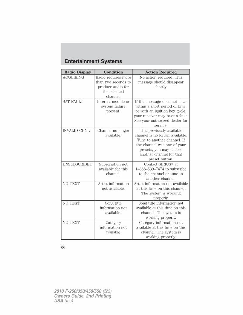
Radio Display Condition Action Required
ACQUIRING Radio requires morethan two seconds to
produce audio forthe selected
channel.
No action required. Thismessage should disappear
shortly.
SAT FAULT Internal module orsystem failure
present.
If this message does not clearwithin a short period of time,or with an ignition key cycle,
your receiver may have a fault.See your authorized dealer for
service.INVALID CHNL Channel no longer
available.This previously available
channel is no longer available.Tune to another channel. Ifthe channel was one of your
presets, you may chooseanother channel for that
preset button.UNSUBSCRIBED Subscription not
available for thischannel.
Contact SIRIUS� at1–888–539–7474 to subscribe
to the channel or tune toanother channel.
NO TEXT Artist informationnot available.
Artist information not availableat this time on this channel.
The system is workingproperly.
NO TEXT Song titleinformation not
available.
Song title information notavailable at this time on this
channel. The system isworking properly.
NO TEXT Categoryinformation not
available.
Category information notavailable at this time on this
channel. The system isworking properly.
Entertainment Systems
66
2010 F-250/350/450/550 (f23)Owners Guide, 2nd PrintingUSA (fus)
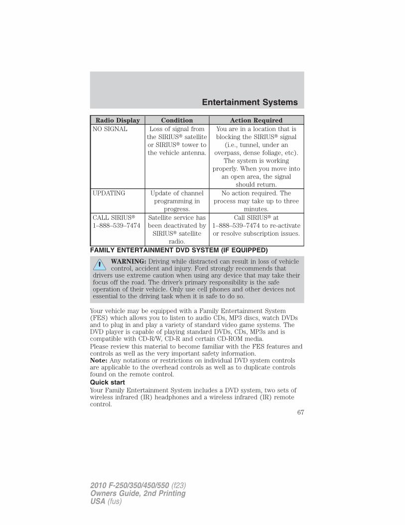
Radio Display Condition Action Required
NO SIGNAL Loss of signal fromthe SIRIUS� satelliteor SIRIUS� tower tothe vehicle antenna.
You are in a location that isblocking the SIRIUS� signal
(i.e., tunnel, under anoverpass, dense foliage, etc).
The system is workingproperly. When you move into
an open area, the signalshould return.
UPDATING Update of channelprogramming in
progress.
No action required. Theprocess may take up to three
minutes.CALL SIRIUS�1–888–539–7474
Satellite service hasbeen deactivated by
SIRIUS� satelliteradio.
Call SIRIUS� at1–888–539–7474 to re-activateor resolve subscription issues.
FAMILY ENTERTAINMENT DVD SYSTEM (IF EQUIPPED)
WARNING: Driving while distracted can result in loss of vehiclecontrol, accident and injury. Ford strongly recommends that
drivers use extreme caution when using any device that may take theirfocus off the road. The driver’s primary responsibility is the safeoperation of their vehicle. Only use cell phones and other devices notessential to the driving task when it is safe to do so.
Your vehicle may be equipped with a Family Entertainment System(FES) which allows you to listen to audio CDs, MP3 discs, watch DVDsand to plug in and play a variety of standard video game systems. TheDVD player is capable of playing standard DVDs, CDs, MP3s and iscompatible with CD-R/W, CD-R and certain CD-ROM media.Please review this material to become familiar with the FES features andcontrols as well as the very important safety information.Note: Any notations or restrictions on individual DVD system controlsare applicable to the overhead controls as well as to duplicate controlsfound on the remote control.Quick startYour Family Entertainment System includes a DVD system, two sets ofwireless infrared (IR) headphones and a wireless infrared (IR) remotecontrol.
Entertainment Systems
67
2010 F-250/350/450/550 (f23)Owners Guide, 2nd PrintingUSA (fus)
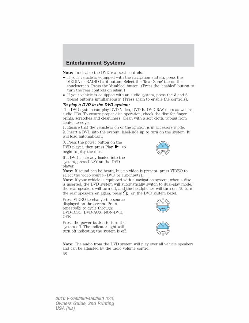
Note: To disable the DVD rear-seat controls:• If your vehicle is equipped with the navigation system, press the
MEDIA or RADIO hard button. Select the ’Rear Zone’ tab on thetouchscreen. Press the ’disabled’ button. (Press the ’enabled’ button toturn the rear controls on again.)
• If your vehicle is equipped with an audio system, press the 3 and 5preset buttons simultaneously. (Press again to enable the controls).
To play a DVD in the DVD system:The DVD system can play DVD-Video, DVD-R, DVD-R/W discs as well asaudio CDs. To ensure proper disc operation, check the disc for fingerprints, scratches and cleanliness. Clean with a soft cloth, wiping fromcenter to edge.1. Ensure that the vehicle is on or the ignition is in accessory mode.2. Insert a DVD into the system, label-side up to turn on the system. Itwill load automatically.
3. Press the power button on theDVD player, then press Play tobegin to play the disc.
If a DVD is already loaded into thesystem, press PLAY on the DVDplayer.Note: If sound can be heard, but no video is present, press VIDEO toselect the video source (DVD or aux-inputs).Note: If your vehicle is equipped with a navigation system, when a discis inserted, the DVD system will automatically switch to dual-play mode;the rear speakers will turn off, and the headphones will turn on. To turnthe rear speakers on again, press on the DVD system bezel.
Press VIDEO to change the sourcedisplayed on the screen. Pressrepeatedly to cycle through:DVD-DISC, DVD-AUX, NON-DVD,OFF.
Press the power button to turn thesystem off. The indicator light willturn off indicating the system is off.
Note: The audio from the DVD system will play over all vehicle speakersand can be adjusted by the radio volume control.
Entertainment Systems
68
2010 F-250/350/450/550 (f23)Owners Guide, 2nd PrintingUSA (fus)
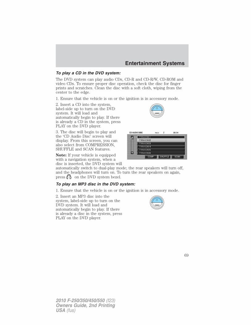
To play a CD in the DVD system:
The DVD system can play audio CDs, CD-R and CD-R/W, CD-ROM andvideo CDs. To ensure proper disc operation, check the disc for fingerprints and scratches. Clean the disc with a soft cloth, wiping from thecenter to the edge.
1. Ensure that the vehicle is on or the ignition is in accessory mode.
2. Insert a CD into the system,label-side up to turn on the DVDsystem. It will load andautomatically begin to play. If thereis already a CD in the system, pressPLAY on the DVD player.
3. The disc will begin to play andthe ‘CD Audio Disc’ screen willdisplay. From this screen, you canalso select from COMPRESSION,SHUFFLE and SCAN features.
Note: If your vehicle is equippedwith a navigation system, when adisc is inserted, the DVD system willautomatically switch to dual-play mode; the rear speakers will turn off,and the headphones will turn on. To turn the rear speakers on again,press on the DVD system bezel.
To play an MP3 disc in the DVD system:
1. Ensure that the vehicle is on or the ignition is in accessory mode.
2. Insert an MP3 disc into thesystem, label-side up to turn on theDVD system. It will load andautomatically begin to play. If thereis already a disc in the system, pressPLAY on the DVD player.
Entertainment Systems
69
2010 F-250/350/450/550 (f23)Owners Guide, 2nd PrintingUSA (fus)
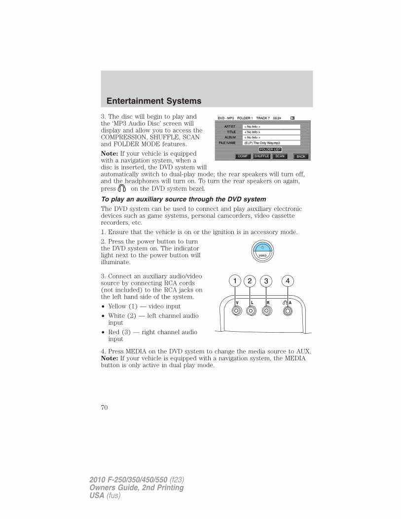
3. The disc will begin to play andthe ‘MP3 Audio Disc’ screen willdisplay and allow you to access theCOMPRESSION, SHUFFLE, SCANand FOLDER MODE features.
Note: If your vehicle is equippedwith a navigation system, when adisc is inserted, the DVD system willautomatically switch to dual-play mode; the rear speakers will turn off,and the headphones will turn on. To turn the rear speakers on again,press on the DVD system bezel.
To play an auxiliary source through the DVD systemThe DVD system can be used to connect and play auxiliary electronicdevices such as game systems, personal camcorders, video cassetterecorders, etc.
1. Ensure that the vehicle is on or the ignition is in accessory mode.
2. Press the power button to turnthe DVD system on. The indicatorlight next to the power button willilluminate.
3. Connect an auxiliary audio/videosource by connecting RCA cords(not included) to the RCA jacks onthe left hand side of the system.
• Yellow (1) — video input
• White (2) — left channel audioinput
• Red (3) — right channel audioinput
4. Press MEDIA on the DVD system to change the media source to AUX.Note: If your vehicle is equipped with a navigation system, the MEDIAbutton is only active in dual play mode.
Entertainment Systems
70
2010 F-250/350/450/550 (f23)Owners Guide, 2nd PrintingUSA (fus)
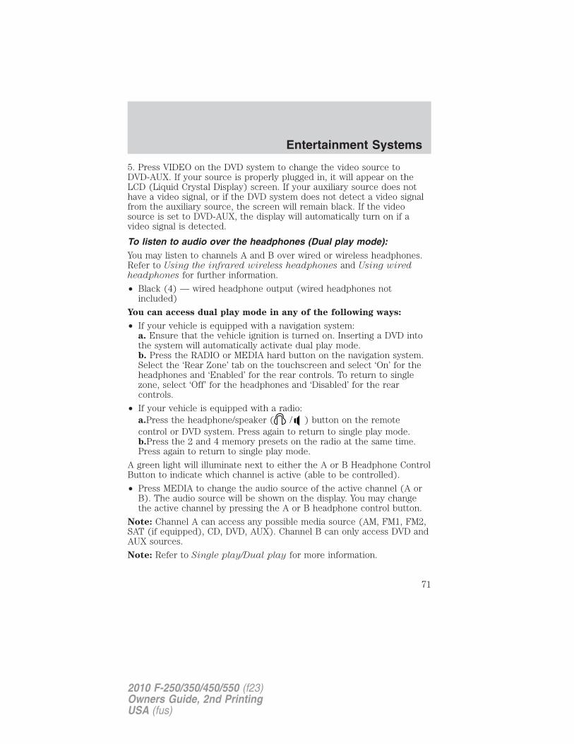
5. Press VIDEO on the DVD system to change the video source toDVD-AUX. If your source is properly plugged in, it will appear on theLCD (Liquid Crystal Display) screen. If your auxiliary source does nothave a video signal, or if the DVD system does not detect a video signalfrom the auxiliary source, the screen will remain black. If the videosource is set to DVD-AUX, the display will automatically turn on if avideo signal is detected.
To listen to audio over the headphones (Dual play mode):You may listen to channels A and B over wired or wireless headphones.Refer to Using the infrared wireless headphones and Using wiredheadphones for further information.
• Black (4) — wired headphone output (wired headphones notincluded)
You can access dual play mode in any of the following ways:
• If your vehicle is equipped with a navigation system:a. Ensure that the vehicle ignition is turned on. Inserting a DVD intothe system will automatically activate dual play mode.b. Press the RADIO or MEDIA hard button on the navigation system.Select the ‘Rear Zone’ tab on the touchscreen and select ‘On’ for theheadphones and ‘Enabled’ for the rear controls. To return to singlezone, select ‘Off’ for the headphones and ‘Disabled’ for the rearcontrols.
• If your vehicle is equipped with a radio:a.Press the headphone/speaker ( / ) button on the remotecontrol or DVD system. Press again to return to single play mode.b.Press the 2 and 4 memory presets on the radio at the same time.Press again to return to single play mode.
A green light will illuminate next to either the A or B Headphone ControlButton to indicate which channel is active (able to be controlled).
• Press MEDIA to change the audio source of the active channel (A orB). The audio source will be shown on the display. You may changethe active channel by pressing the A or B headphone control button.
Note: Channel A can access any possible media source (AM, FM1, FM2,SAT (if equipped), CD, DVD, AUX). Channel B can only access DVD andAUX sources.
Note: Refer to Single play/Dual play for more information.
Entertainment Systems
71
2010 F-250/350/450/550 (f23)Owners Guide, 2nd PrintingUSA (fus)
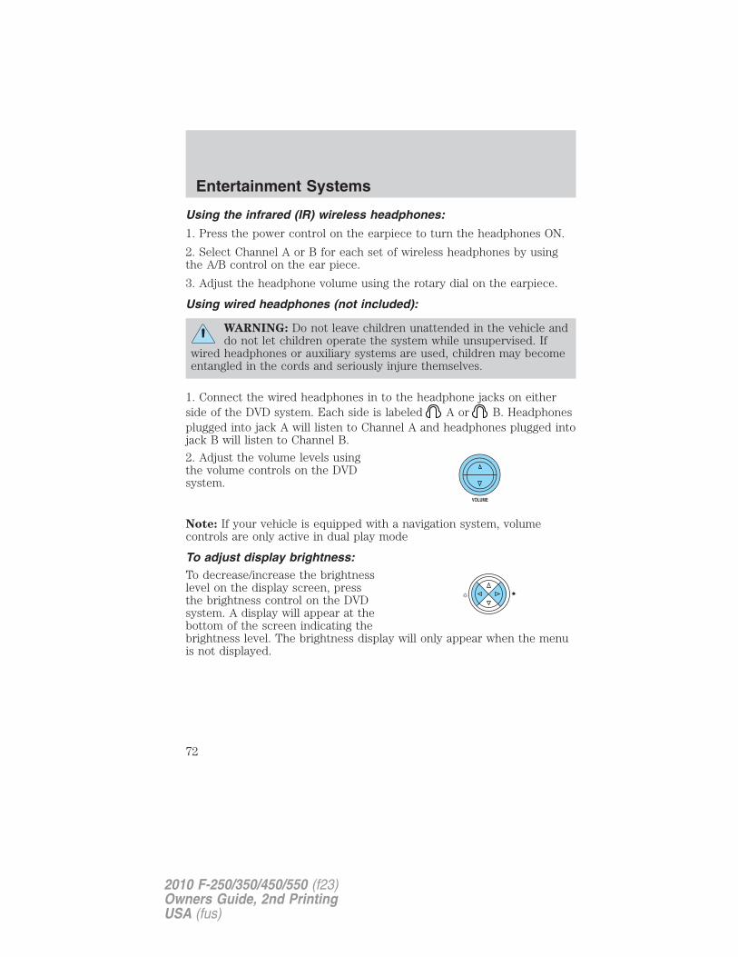
Using the infrared (IR) wireless headphones:
1. Press the power control on the earpiece to turn the headphones ON.
2. Select Channel A or B for each set of wireless headphones by usingthe A/B control on the ear piece.
3. Adjust the headphone volume using the rotary dial on the earpiece.
Using wired headphones (not included):
WARNING: Do not leave children unattended in the vehicle anddo not let children operate the system while unsupervised. If
wired headphones or auxiliary systems are used, children may becomeentangled in the cords and seriously injure themselves.
1. Connect the wired headphones in to the headphone jacks on eitherside of the DVD system. Each side is labeled A or B. Headphonesplugged into jack A will listen to Channel A and headphones plugged intojack B will listen to Channel B.
2. Adjust the volume levels usingthe volume controls on the DVDsystem.
Note: If your vehicle is equipped with a navigation system, volumecontrols are only active in dual play mode
To adjust display brightness:To decrease/increase the brightnesslevel on the display screen, pressthe brightness control on the DVDsystem. A display will appear at thebottom of the screen indicating thebrightness level. The brightness display will only appear when the menuis not displayed.
Entertainment Systems
72
2010 F-250/350/450/550 (f23)Owners Guide, 2nd PrintingUSA (fus)
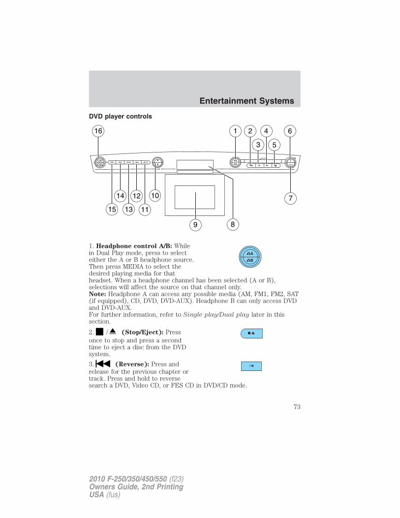
DVD player controls
1. Headphone control A/B: Whilein Dual Play mode, press to selecteither the A or B headphone source.Then press MEDIA to select thedesired playing media for thatheadset. When a headphone channel has been selected (A or B),selections will affect the source on that channel only.Note: Headphone A can access any possible media (AM, FM1, FM2, SAT(if equipped), CD, DVD, DVD-AUX). Headphone B can only access DVDand DVD-AUX.For further information, refer to Single play/Dual play later in thissection.
2. / (Stop/Eject): Pressonce to stop and press a secondtime to eject a disc from the DVDsystem.
3. (Reverse): Press andrelease for the previous chapter ortrack. Press and hold to reversesearch a DVD, Video CD, or FES CD in DVD/CD mode.
A
B VIDEO
VOLUME
MEDIARETURNMENUENTER
1
7
2
3
4
5
6
9
10
11
12
13
14
15
16
8
Entertainment Systems
73
2010 F-250/350/450/550 (f23)Owners Guide, 2nd PrintingUSA (fus)
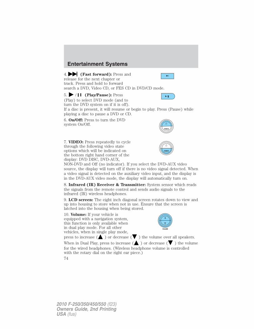
4. (Fast forward): Press andrelease for the next chapter ortrack. Press and hold to forwardsearch a DVD, Video CD, or FES CD in DVD/CD mode.
5. / (Play/Pause): Press(Play) to select DVD mode (and toturn the DVD system on if it is off).If a disc is present, it will resume or begin to play. Press (Pause) whileplaying a disc to pause a DVD or CD.
6. On/Off: Press to turn the DVDsystem On/Off.
7. VIDEO: Press repeatedly to cyclethrough the following video stateoptions which will be indicated onthe bottom right hand corner of thedisplay: DVD DISC, DVD-AUX,NON-DVD and Off (no indicator). If you select the DVD-AUX videosource, the display will turn off if there is no video signal detected. Whena video signal is detected on the auxiliary video input, and the display isin the DVD-AUX video mode, the display will automatically turn on.
8. Infrared (IR) Receiver & Transmitter: System sensor which readsthe signals from the remote control and sends audio signals to theinfrared (IR) wireless headphones.
9. LCD screen: The eight inch diagonal screen rotates down to view andup into housing to store when not in use. Ensure that the screen islatched into the housing when being stored.
10. Volume: If your vehicle isequipped with a navigation system,this function is only available whenin dual play mode. For all othervehicles, when in single play mode,press to increase ( ) or decrease ( ) the volume over all speakers.
When in Dual Play, press to increase ( ) or decrease ( ) the volumefor the wired headphones. (Wireless headphone volume is controlledwith the rotary dial on the right ear piece.)
Entertainment Systems
74
2010 F-250/350/450/550 (f23)Owners Guide, 2nd PrintingUSA (fus)
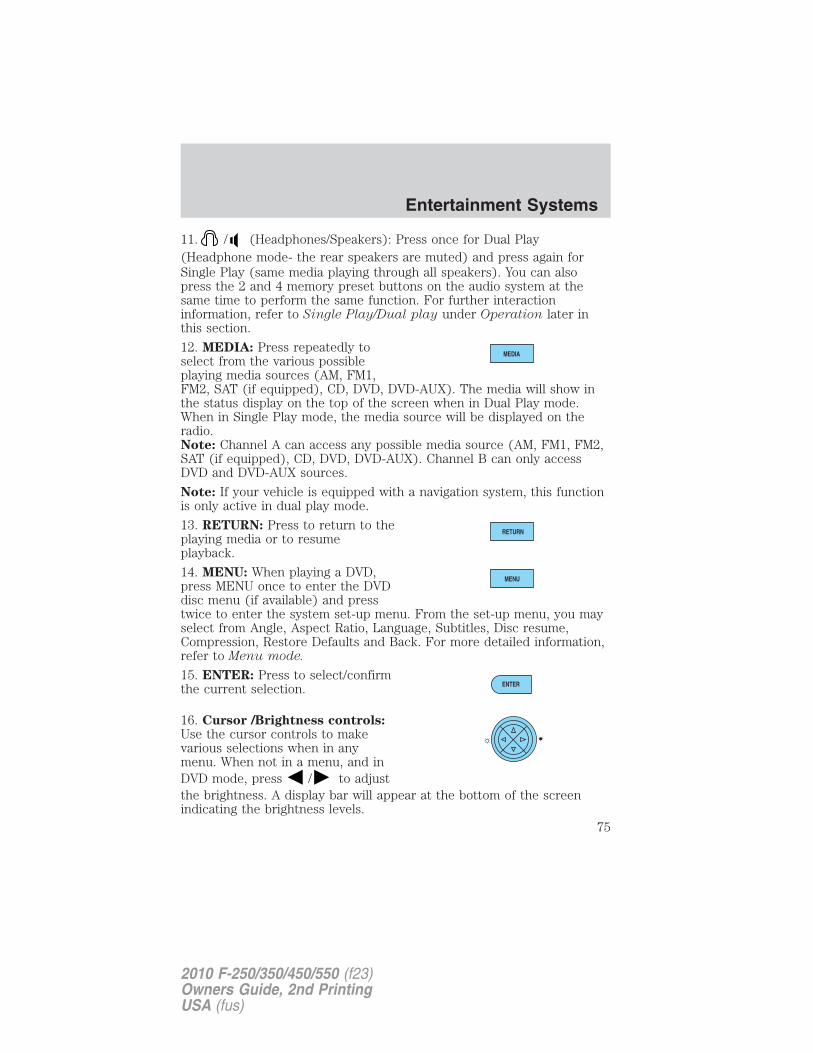
11. / (Headphones/Speakers): Press once for Dual Play(Headphone mode- the rear speakers are muted) and press again forSingle Play (same media playing through all speakers). You can alsopress the 2 and 4 memory preset buttons on the audio system at thesame time to perform the same function. For further interactioninformation, refer to Single Play/Dual play under Operation later inthis section.
12. MEDIA: Press repeatedly toselect from the various possibleplaying media sources (AM, FM1,FM2, SAT (if equipped), CD, DVD, DVD-AUX). The media will show inthe status display on the top of the screen when in Dual Play mode.When in Single Play mode, the media source will be displayed on theradio.Note: Channel A can access any possible media source (AM, FM1, FM2,SAT (if equipped), CD, DVD, DVD-AUX). Channel B can only accessDVD and DVD-AUX sources.
Note: If your vehicle is equipped with a navigation system, this functionis only active in dual play mode.
13. RETURN: Press to return to theplaying media or to resumeplayback.
14. MENU: When playing a DVD,press MENU once to enter the DVDdisc menu (if available) and presstwice to enter the system set-up menu. From the set-up menu, you mayselect from Angle, Aspect Ratio, Language, Subtitles, Disc resume,Compression, Restore Defaults and Back. For more detailed information,refer to Menu mode.
15. ENTER: Press to select/confirmthe current selection.
16. Cursor /Brightness controls:Use the cursor controls to makevarious selections when in anymenu. When not in a menu, and inDVD mode, press / to adjustthe brightness. A display bar will appear at the bottom of the screenindicating the brightness levels.
Entertainment Systems
75
2010 F-250/350/450/550 (f23)Owners Guide, 2nd PrintingUSA (fus)
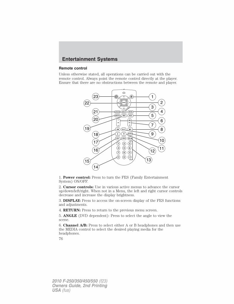
Remote control
Unless otherwise stated, all operations can be carried out with theremote control. Always point the remote control directly at the player.Ensure that there are no obstructions between the remote and player.
1. Power control: Press to turn the FES (Family EntertainmentSystem) ON/OFF.
2. Cursor controls: Use in various active menus to advance the cursorup/down/left/right. When not in a Menu, the left and right cursor controlsdecrease and increase the display brightness.
3. DISPLAY: Press to access the on-screen display of the FES functionsand adjustments.
4. RETURN: Press to return to the previous menu screen.
5. ANGLE (DVD dependent): Press to select the angle to view thescene.
6. Channel A/B: Press to select either A or B headphones and then usethe MEDIA control to select the desired playing media for theheadphones.
Entertainment Systems
76
2010 F-250/350/450/550 (f23)Owners Guide, 2nd PrintingUSA (fus)
7. VOL (Volume): When in Single Play, press to increase ( ) ordecrease ( ) the volume over all speakers. When in Dual Play, press toincrease ( ) or decrease ( ) the volume for the wired headphones.(Wireless headphone volume is controlled with the rotary dial on theright ear piece.)8. Fast Forward/Next: In DVD mode, press and hold for a quickadvance within the DVD. Press and release to advance to the nextchapter. In CD/MP3 mode, press to access the next track.9. Play/Pause: Press to play or pause a DVD.10. SHUFFLE: Press to play all tracks on the current CD/MP3 disc inrandom order.11. STOP: Press to stop the current DVD or CD/MP3.
12. / Speaker/Headphone (Single/Dual Play): Press to togglebetween Single Play (same media playing through all speakers) and DualPlay (headphone mode — the rear speakers are muted). You can alsopress the 2 and 4 memory presets on the audio system at the same timeto perform the same function.
13. Numeric Keypad: Use the numeric controls to enter in a specificCD/MP3 track or DVD chapter to be played.
14. C (Cancel): Press to cancel/clear the numeric input (i.e. chapternumber).
15. MEDIA: Press to cycle through the possible media sources: AM,FM1, FM2, SAT (if equipped), CD, DVD, LINE IN (if equipped),DVD-AUX.Channel B can only access DVD and AUX sources.
16. VIDEO: Press to cycle through video states: DVD-DISC, DVD-AUX,NON-DVD, Off.
17. EJECT: Press to eject a disc from the FES.
18. Fast reverse/Previous: When a DVD is playing, press and hold for aquick reverse within the DVD. Press and release for the previouschapter. Press PLAY to resume normal playback speed and volume.In CD/MP3 mode, press to access the previous track.
19. MENU: Press to access the DVD disc menu for selections. PressMENU again when in the DVD disc menu to access the system set-upmenu.
20. SUBTITLE (DVD dependent): Press to turn the subtitle feature ONor OFF.
Entertainment Systems
77
2010 F-250/350/450/550 (f23)Owners Guide, 2nd PrintingUSA (fus)
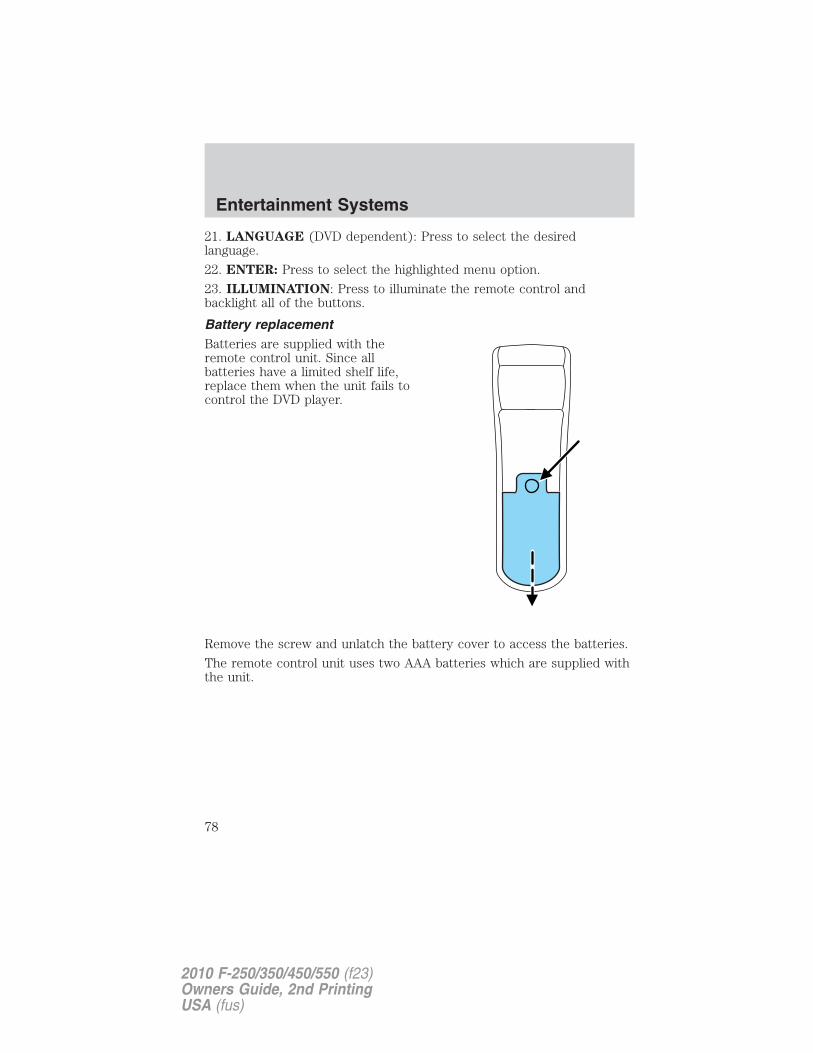
21. LANGUAGE (DVD dependent): Press to select the desiredlanguage.
22. ENTER: Press to select the highlighted menu option.
23. ILLUMINATION: Press to illuminate the remote control andbacklight all of the buttons.
Battery replacementBatteries are supplied with theremote control unit. Since allbatteries have a limited shelf life,replace them when the unit fails tocontrol the DVD player.
Remove the screw and unlatch the battery cover to access the batteries.
The remote control unit uses two AAA batteries which are supplied withthe unit.
Entertainment Systems
78
2010 F-250/350/450/550 (f23)Owners Guide, 2nd PrintingUSA (fus)
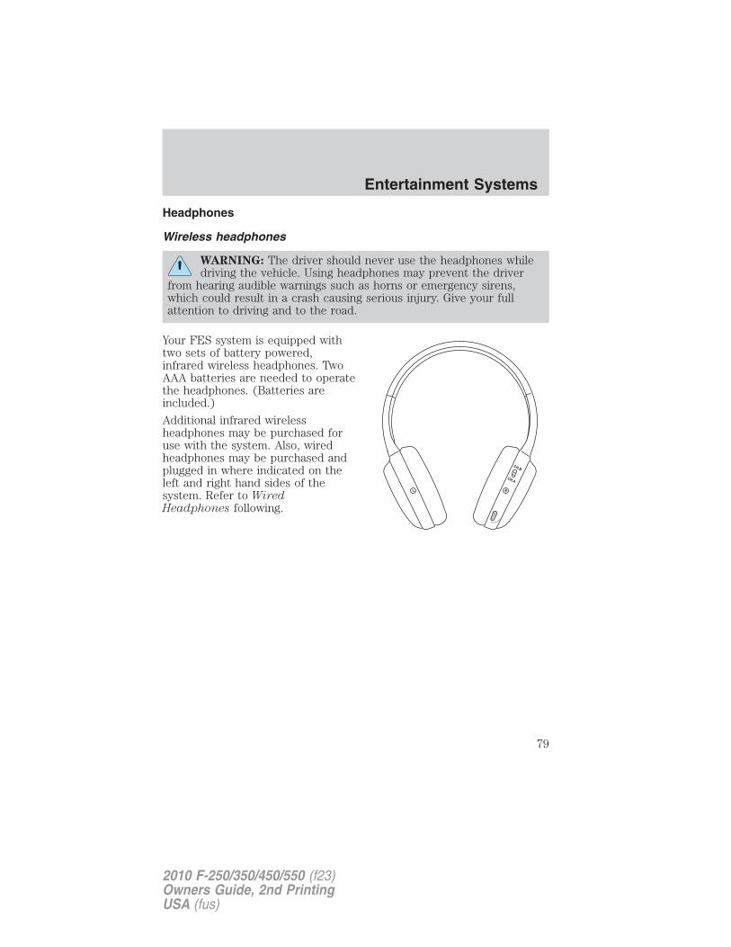
Headphones
Wireless headphones
WARNING: The driver should never use the headphones whiledriving the vehicle. Using headphones may prevent the driver
from hearing audible warnings such as horns or emergency sirens,which could result in a crash causing serious injury. Give your fullattention to driving and to the road.
Your FES system is equipped withtwo sets of battery powered,infrared wireless headphones. TwoAAA batteries are needed to operatethe headphones. (Batteries areincluded.)
Additional infrared wirelessheadphones may be purchased foruse with the system. Also, wiredheadphones may be purchased andplugged in where indicated on theleft and right hand sides of thesystem. Refer to WiredHeadphones following.
Entertainment Systems
79
2010 F-250/350/450/550 (f23)Owners Guide, 2nd PrintingUSA (fus)
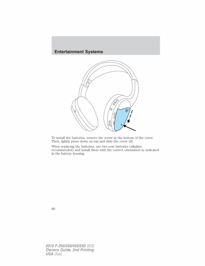
To install the batteries, remove the screw at the bottom of the cover.Then, lightly press down on top and slide the cover off.
When replacing the batteries, use two new batteries (alkalinerecommended) and install them with the correct orientation as indicatedin the battery housing.
Entertainment Systems
80
2010 F-250/350/450/550 (f23)Owners Guide, 2nd PrintingUSA (fus)
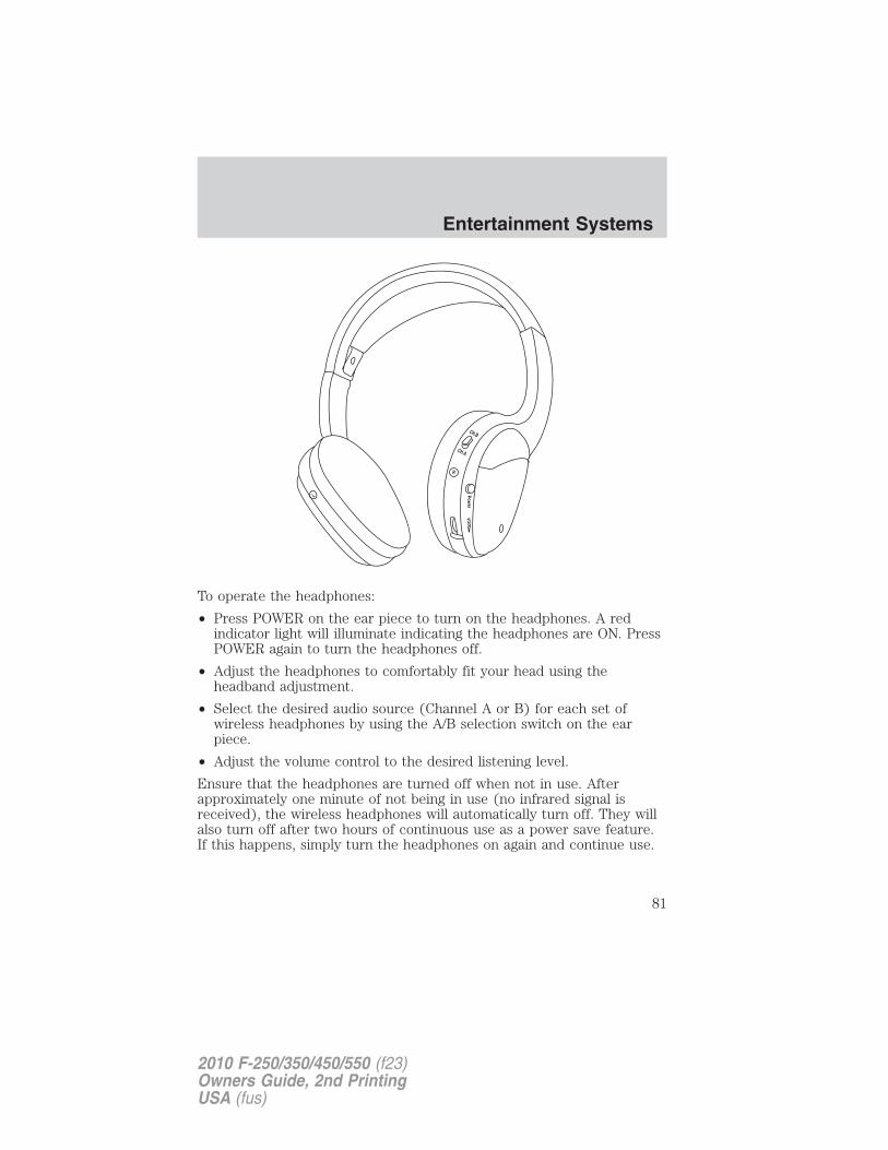
To operate the headphones:
• Press POWER on the ear piece to turn on the headphones. A redindicator light will illuminate indicating the headphones are ON. PressPOWER again to turn the headphones off.
• Adjust the headphones to comfortably fit your head using theheadband adjustment.
• Select the desired audio source (Channel A or B) for each set ofwireless headphones by using the A/B selection switch on the earpiece.
• Adjust the volume control to the desired listening level.
Ensure that the headphones are turned off when not in use. Afterapproximately one minute of not being in use (no infrared signal isreceived), the wireless headphones will automatically turn off. They willalso turn off after two hours of continuous use as a power save feature.If this happens, simply turn the headphones on again and continue use.
Entertainment Systems
81
2010 F-250/350/450/550 (f23)Owners Guide, 2nd PrintingUSA (fus)
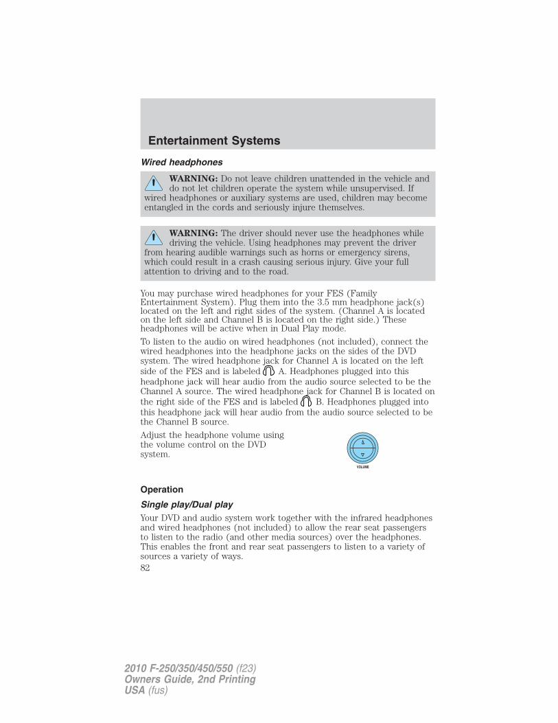
Wired headphones
WARNING: Do not leave children unattended in the vehicle anddo not let children operate the system while unsupervised. If
wired headphones or auxiliary systems are used, children may becomeentangled in the cords and seriously injure themselves.
WARNING: The driver should never use the headphones whiledriving the vehicle. Using headphones may prevent the driver
from hearing audible warnings such as horns or emergency sirens,which could result in a crash causing serious injury. Give your fullattention to driving and to the road.
You may purchase wired headphones for your FES (FamilyEntertainment System). Plug them into the 3.5 mm headphone jack(s)located on the left and right sides of the system. (Channel A is locatedon the left side and Channel B is located on the right side.) Theseheadphones will be active when in Dual Play mode.
To listen to the audio on wired headphones (not included), connect thewired headphones into the headphone jacks on the sides of the DVDsystem. The wired headphone jack for Channel A is located on the leftside of the FES and is labeled A. Headphones plugged into thisheadphone jack will hear audio from the audio source selected to be theChannel A source. The wired headphone jack for Channel B is located onthe right side of the FES and is labeled B. Headphones plugged intothis headphone jack will hear audio from the audio source selected to bethe Channel B source.
Adjust the headphone volume usingthe volume control on the DVDsystem.
Operation
Single play/Dual playYour DVD and audio system work together with the infrared headphonesand wired headphones (not included) to allow the rear seat passengersto listen to the radio (and other media sources) over the headphones.This enables the front and rear seat passengers to listen to a variety ofsources a variety of ways.
Entertainment Systems
82
2010 F-250/350/450/550 (f23)Owners Guide, 2nd PrintingUSA (fus)
Single Play: Single play consists of all occupants in the vehicle listeningto the same playing media over the front and rear speakers. When theDVD system is on, and the same source is playing through the front andrear speakers, SINGLE PLAY will appear in the front radio display.
Dual Play: Dual play is when the rear seat passengers choose to listento a different playing media than the front seat passengers. With theDVD and Rear Seat Controls turned ON, the rear seat passengers maychoose to listen to the radio, CD, MP3, DVD, DVD-AUX or SYNC� (ifequipped) media sources over headphones while the front speakers playthe chosen selection for the front audio system, they may listen toanother over the headphones. DUAL PLAY will appear in the radiodisplay.
When both the front seat passengers and the rear seat passengers listento the same audio source, SHARED MODE will appear on the radio.
Note: If the front seat passengers are listening to the radio, the rear seatpassengers can also listen to the radio; however, they will be limited tolistening to the same radio channel.
You can access dual play mode in any of the following ways:
• If your vehicle is equipped with a navigation system:a. Ensure that the vehicle ignition is turned on. Inserting a DVD intothe system will automatically activate dual play mode.b. Press the RADIO or MEDIA hard button on the navigation system.Select the ‘Rear Zone’ tab on the touchscreen and select ‘On’ for theheadphones and ‘Enabled’ for the rear controls. To return to singlezone, select ‘Off’ for the headphones and ‘Disabled’ for the rearcontrols.
• If your vehicle is equipped with a radio:a.Press the headphone/speaker ( / ) button on the remotecontrol or DVD system. Press again to return to single play mode.b.Press the 2 and 4 memory presets on the radio at the same time.Press again to return to single play mode.
The headphone control will now be active and a green light next to theA or B headphone control buttons will illuminate. The system can outputtwo different audio sources over the headphones. These are calledChannel A and Channel B. Both Channel A and Channel B can belistened to on the wired headphones (not included) or on the infrared(IR) wireless headphones.
Entertainment Systems
83
2010 F-250/350/450/550 (f23)Owners Guide, 2nd PrintingUSA (fus)
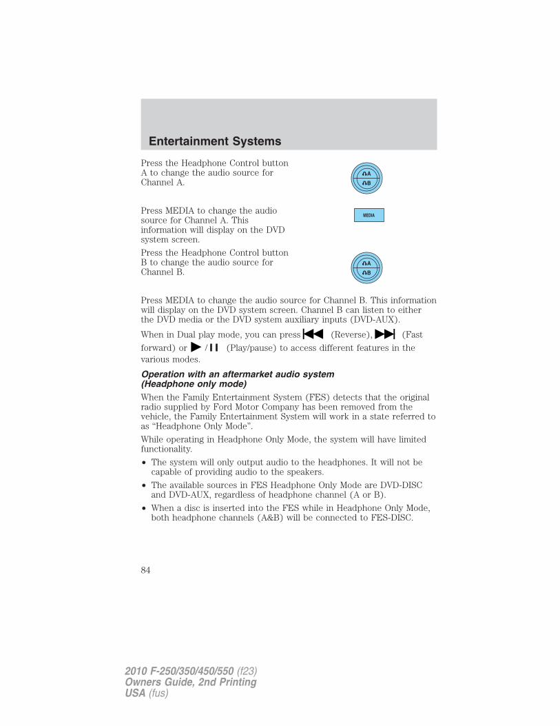
Press the Headphone Control buttonA to change the audio source forChannel A.
Press MEDIA to change the audiosource for Channel A. Thisinformation will display on the DVDsystem screen.
Press the Headphone Control buttonB to change the audio source forChannel B.
Press MEDIA to change the audio source for Channel B. This informationwill display on the DVD system screen. Channel B can listen to eitherthe DVD media or the DVD system auxiliary inputs (DVD-AUX).
When in Dual play mode, you can press (Reverse), (Fast
forward) or / (Play/pause) to access different features in thevarious modes.
Operation with an aftermarket audio system(Headphone only mode)When the Family Entertainment System (FES) detects that the originalradio supplied by Ford Motor Company has been removed from thevehicle, the Family Entertainment System will work in a state referred toas “Headphone Only Mode”.
While operating in Headphone Only Mode, the system will have limitedfunctionality.
• The system will only output audio to the headphones. It will not becapable of providing audio to the speakers.
• The available sources in FES Headphone Only Mode are DVD-DISCand DVD-AUX, regardless of headphone channel (A or B).
• When a disc is inserted into the FES while in Headphone Only Mode,both headphone channels (A&B) will be connected to FES-DISC.
Entertainment Systems
84
2010 F-250/350/450/550 (f23)Owners Guide, 2nd PrintingUSA (fus)
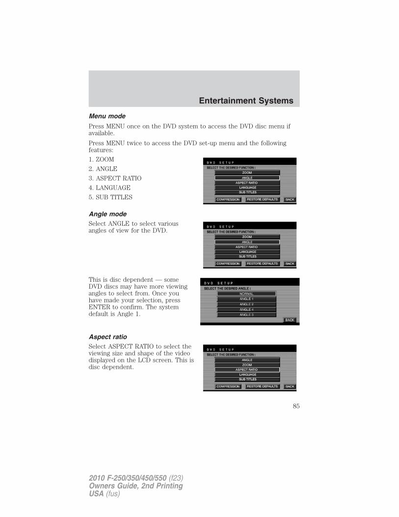
Menu mode
Press MENU once on the DVD system to access the DVD disc menu ifavailable.
Press MENU twice to access the DVD set-up menu and the followingfeatures:
1. ZOOM
2. ANGLE
3. ASPECT RATIO
4. LANGUAGE
5. SUB TITLES
Angle modeSelect ANGLE to select variousangles of view for the DVD.
This is disc dependent — someDVD discs may have more viewingangles to select from. Once youhave made your selection, pressENTER to confirm. The systemdefault is Angle 1.
Aspect ratioSelect ASPECT RATIO to select theviewing size and shape of the videodisplayed on the LCD screen. This isdisc dependent.
Entertainment Systems
85
2010 F-250/350/450/550 (f23)Owners Guide, 2nd PrintingUSA (fus)
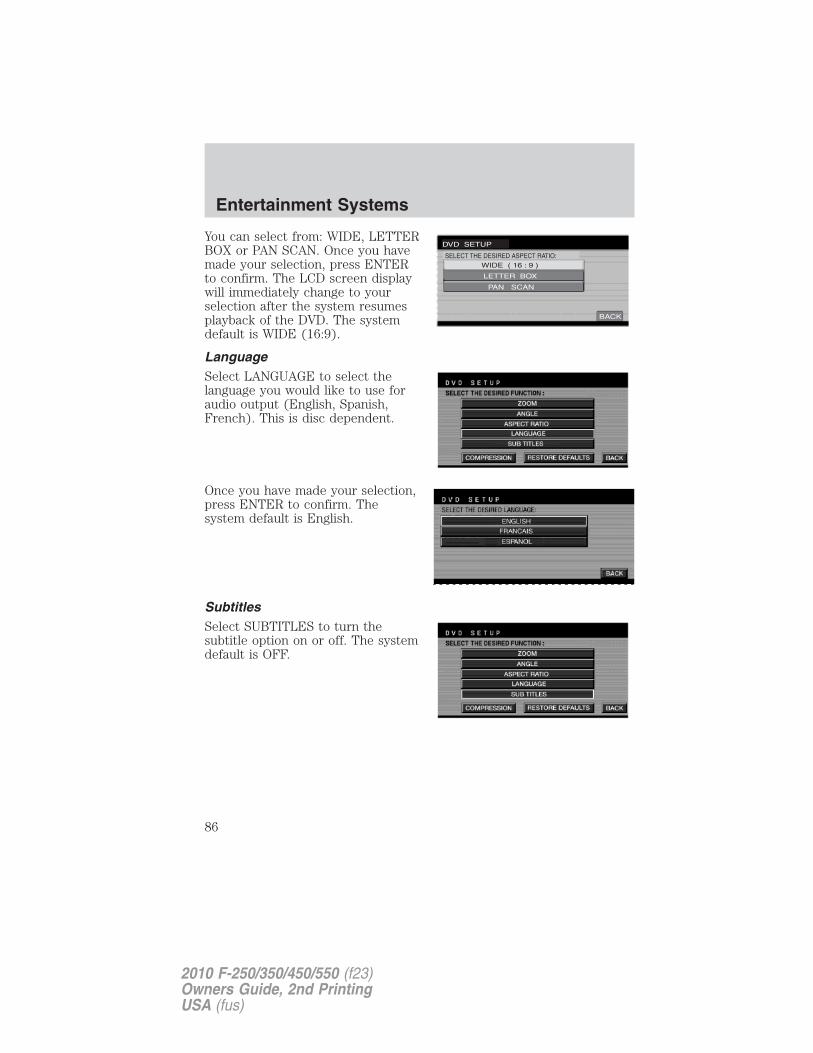
You can select from: WIDE, LETTERBOX or PAN SCAN. Once you havemade your selection, press ENTERto confirm. The LCD screen displaywill immediately change to yourselection after the system resumesplayback of the DVD. The systemdefault is WIDE (16:9).
LanguageSelect LANGUAGE to select thelanguage you would like to use foraudio output (English, Spanish,French). This is disc dependent.
Once you have made your selection,press ENTER to confirm. Thesystem default is English.
SubtitlesSelect SUBTITLES to turn thesubtitle option on or off. The systemdefault is OFF.
Entertainment Systems
86
2010 F-250/350/450/550 (f23)Owners Guide, 2nd PrintingUSA (fus)
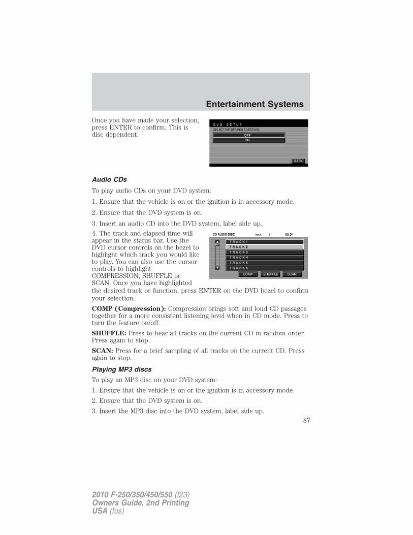
Once you have made your selection,press ENTER to confirm. This isdisc dependent.
Audio CDs
To play audio CDs on your DVD system:
1. Ensure that the vehicle is on or the ignition is in accessory mode.
2. Ensure that the DVD system is on.
3. Insert an audio CD into the DVD system, label side up.
4. The track and elapsed time willappear in the status bar. Use theDVD cursor controls on the bezel tohighlight which track you would liketo play. You can also use the cursorcontrols to highlightCOMPRESSION, SHUFFLE orSCAN. Once you have highlightedthe desired track or function, press ENTER on the DVD bezel to confirmyour selection.
COMP (Compression): Compression brings soft and loud CD passagestogether for a more consistent listening level when in CD mode. Press toturn the feature on/off.
SHUFFLE: Press to hear all tracks on the current CD in random order.Press again to stop.
SCAN: Press for a brief sampling of all tracks on the current CD. Pressagain to stop.
Playing MP3 discs
To play an MP3 disc on your DVD system:
1. Ensure that the vehicle is on or the ignition is in accessory mode.
2. Ensure that the DVD system is on.
3. Insert the MP3 disc into the DVD system, label side up.
Entertainment Systems
87
2010 F-250/350/450/550 (f23)Owners Guide, 2nd PrintingUSA (fus)
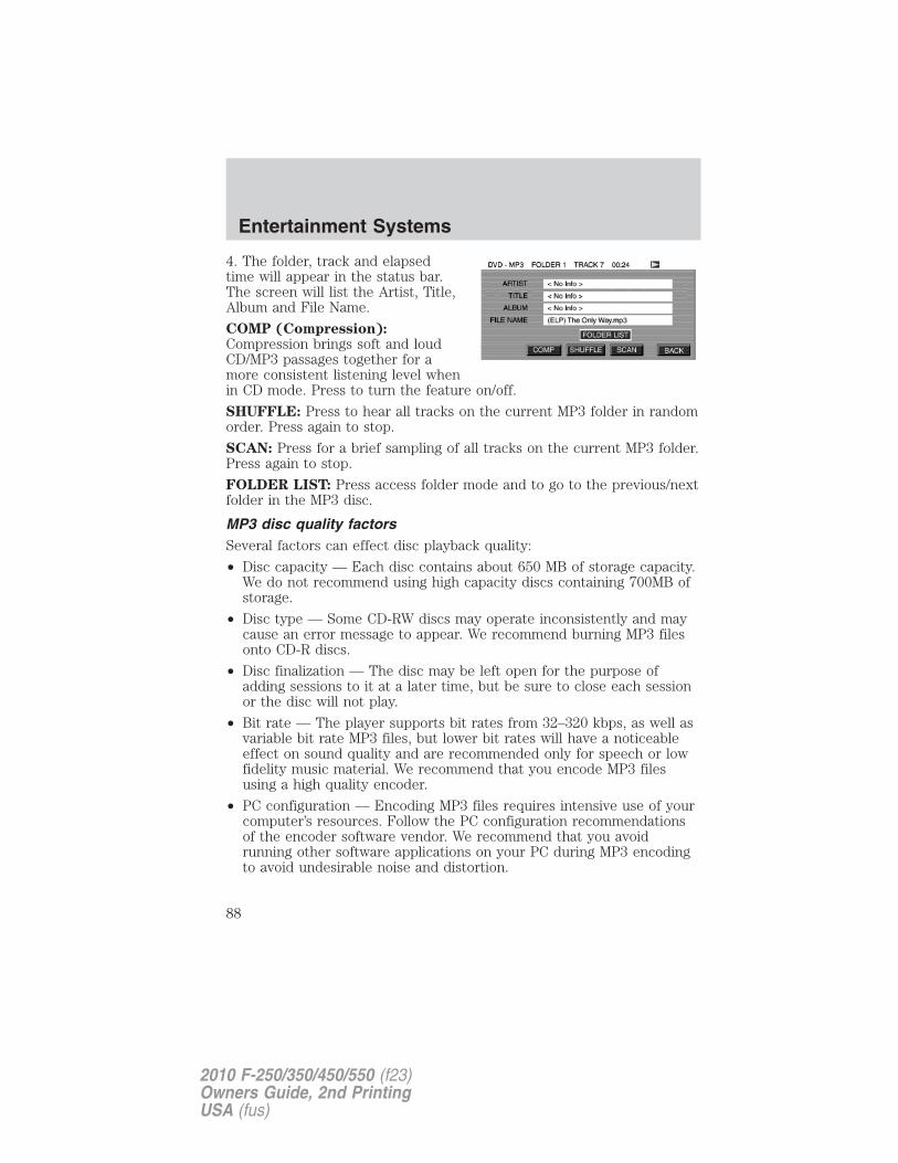
4. The folder, track and elapsedtime will appear in the status bar.The screen will list the Artist, Title,Album and File Name.
COMP (Compression):Compression brings soft and loudCD/MP3 passages together for amore consistent listening level whenin CD mode. Press to turn the feature on/off.
SHUFFLE: Press to hear all tracks on the current MP3 folder in randomorder. Press again to stop.
SCAN: Press for a brief sampling of all tracks on the current MP3 folder.Press again to stop.
FOLDER LIST: Press access folder mode and to go to the previous/nextfolder in the MP3 disc.
MP3 disc quality factorsSeveral factors can effect disc playback quality:
• Disc capacity — Each disc contains about 650 MB of storage capacity.We do not recommend using high capacity discs containing 700MB ofstorage.
• Disc type — Some CD-RW discs may operate inconsistently and maycause an error message to appear. We recommend burning MP3 filesonto CD-R discs.
• Disc finalization — The disc may be left open for the purpose ofadding sessions to it at a later time, but be sure to close each sessionor the disc will not play.
• Bit rate — The player supports bit rates from 32–320 kbps, as well asvariable bit rate MP3 files, but lower bit rates will have a noticeableeffect on sound quality and are recommended only for speech or lowfidelity music material. We recommend that you encode MP3 filesusing a high quality encoder.
• PC configuration — Encoding MP3 files requires intensive use of yourcomputer’s resources. Follow the PC configuration recommendationsof the encoder software vendor. We recommend that you avoidrunning other software applications on your PC during MP3 encodingto avoid undesirable noise and distortion.
Entertainment Systems
88
2010 F-250/350/450/550 (f23)Owners Guide, 2nd PrintingUSA (fus)
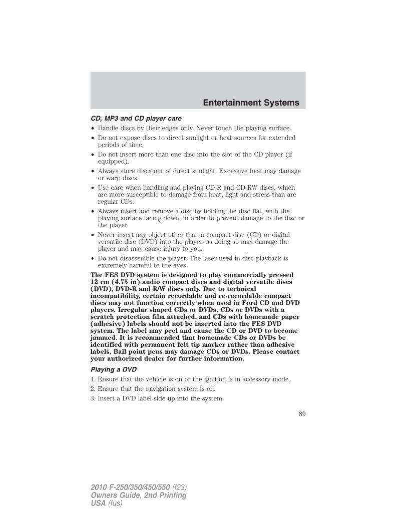
CD, MP3 and CD player care• Handle discs by their edges only. Never touch the playing surface.
• Do not expose discs to direct sunlight or heat sources for extendedperiods of time.
• Do not insert more than one disc into the slot of the CD player (ifequipped).
• Always store discs out of direct sunlight. Excessive heat may damageor warp discs.
• Use care when handling and playing CD-R and CD-RW discs, whichare more susceptible to damage from heat, light and stress than areregular CDs.
• Always insert and remove a disc by holding the disc flat, with theplaying surface facing down, in order to prevent damage to the disc orthe player.
• Never insert any object other than a compact disc (CD) or digitalversatile disc (DVD) into the player, as doing so may damage theplayer and may cause injury to you.
• Do not disassemble the player. The laser used in disc playback isextremely harmful to the eyes.
The FES DVD system is designed to play commercially pressed12 cm (4.75 in) audio compact discs and digital versatile discs(DVD), DVD-R and R/W discs only. Due to technicalincompatibility, certain recordable and re-recordable compactdiscs may not function correctly when used in Ford CD and DVDplayers. Irregular shaped CDs or DVDs, CDs or DVDs with ascratch protection film attached, and CDs with homemade paper(adhesive) labels should not be inserted into the FES DVDsystem. The label may peel and cause the CD or DVD to becomejammed. It is recommended that homemade CDs or DVDs beidentified with permanent felt tip marker rather than adhesivelabels. Ball point pens may damage CDs or DVDs. Please contactyour authorized dealer for further information.
Playing a DVD1. Ensure that the vehicle is on or the ignition is in accessory mode.
2. Ensure that the navigation system is on.
3. Insert a DVD label-side up into the system.
Entertainment Systems
89
2010 F-250/350/450/550 (f23)Owners Guide, 2nd PrintingUSA (fus)
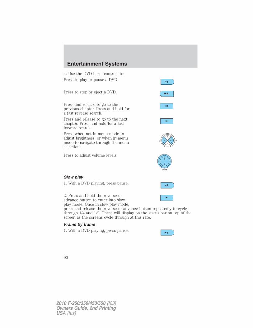
4. Use the DVD bezel controls to:
Press to play or pause a DVD.
Press to stop or eject a DVD.
Press and release to go to theprevious chapter. Press and hold fora fast reverse search.
Press and release to go to the nextchapter. Press and hold for a fastforward search.
Press when not in menu mode toadjust brightness, or when in menumode to navigate through the menuselections.
Press to adjust volume levels.
Slow play1. With a DVD playing, press pause.
2. Press and hold the reverse oradvance button to enter into slowplay mode. Once in slow play mode,press and release the reverse or advance button repeatedly to cyclethrough 1/4 and 1/2. These will display on the status bar on top of thescreen as the screens cycle through at this rate.
Frame by frame1. With a DVD playing, press pause.
Entertainment Systems
90
2010 F-250/350/450/550 (f23)Owners Guide, 2nd PrintingUSA (fus)
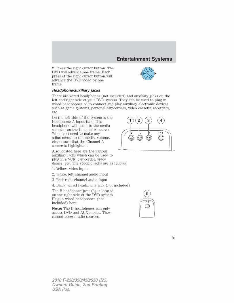
2. Press the right cursor button. TheDVD will advance one frame. Eachpress of the right cursor button willadvance the DVD video by oneframe.
Headphone/auxiliary jacksThere are wired headphones (not included) and auxiliary jacks on theleft and right side of your DVD system. They can be used to plug inwired headphones or to connect and play auxiliary electronic devicessuch as game systems, personal camcorders, video cassette recorders,etc.
On the left side of the system is theHeadphone A input jack. Thisheadphone will listen to the mediaselected on the Channel A source.When you need to make anyadjustments to the media, volume,etc, ensure that the Channel Asource is highlighted.
Also located here are the variousauxiliary jacks which can be used toplug in a VCR, camcorder, videogames, etc. The specific jacks are as follows:
1. Yellow: video input
2. White: left channel audio input
3. Red: right channel audio input
4. Black: wired headphone jack (not included)
The B headphone jack (5) is locatedon the right side of the DVD system.Plug in wired headphones (notincluded) here.
Note: The B headphones can onlyaccess DVD and AUX modes. Theycannot access radio sources.
Entertainment Systems
91
2010 F-250/350/450/550 (f23)Owners Guide, 2nd PrintingUSA (fus)
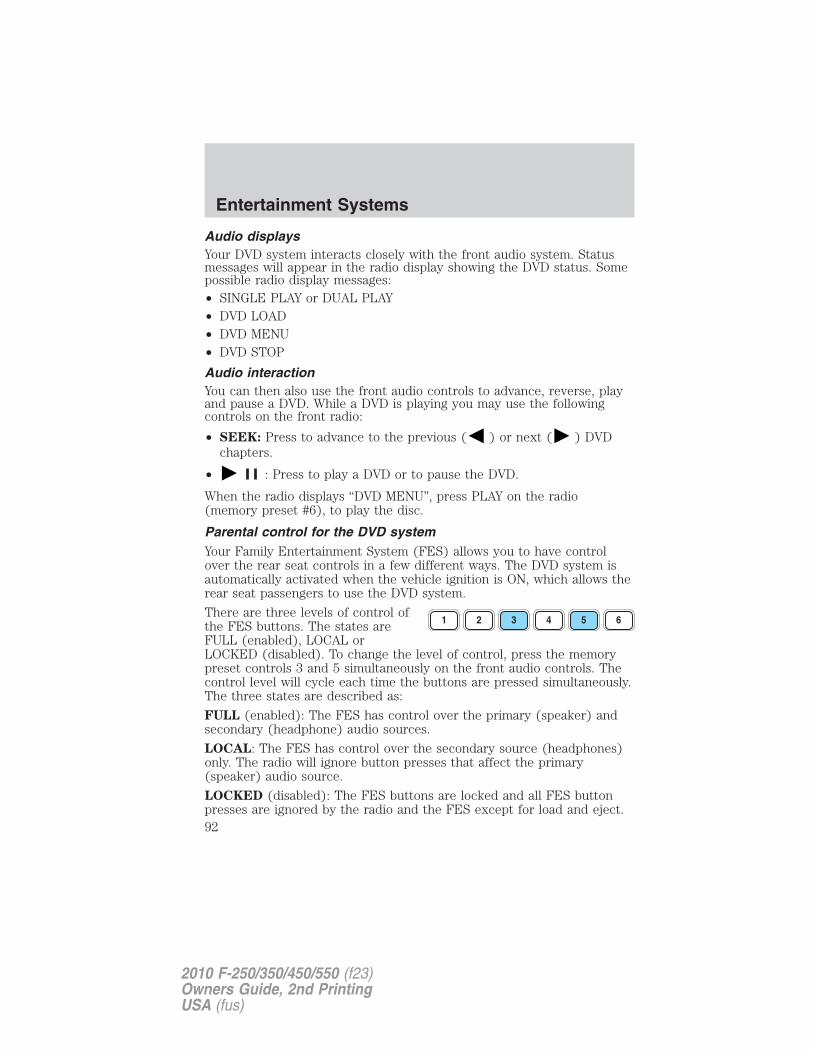
Audio displaysYour DVD system interacts closely with the front audio system. Statusmessages will appear in the radio display showing the DVD status. Somepossible radio display messages:• SINGLE PLAY or DUAL PLAY• DVD LOAD• DVD MENU• DVD STOP
Audio interactionYou can then also use the front audio controls to advance, reverse, playand pause a DVD. While a DVD is playing you may use the followingcontrols on the front radio:
• SEEK: Press to advance to the previous ( ) or next ( ) DVDchapters.
• : Press to play a DVD or to pause the DVD.
When the radio displays “DVD MENU”, press PLAY on the radio(memory preset #6), to play the disc.
Parental control for the DVD systemYour Family Entertainment System (FES) allows you to have controlover the rear seat controls in a few different ways. The DVD system isautomatically activated when the vehicle ignition is ON, which allows therear seat passengers to use the DVD system.
There are three levels of control ofthe FES buttons. The states areFULL (enabled), LOCAL orLOCKED (disabled). To change the level of control, press the memorypreset controls 3 and 5 simultaneously on the front audio controls. Thecontrol level will cycle each time the buttons are pressed simultaneously.The three states are described as:
FULL (enabled): The FES has control over the primary (speaker) andsecondary (headphone) audio sources.
LOCAL: The FES has control over the secondary source (headphones)only. The radio will ignore button presses that affect the primary(speaker) audio source.
LOCKED (disabled): The FES buttons are locked and all FES buttonpresses are ignored by the radio and the FES except for load and eject.
Entertainment Systems
92
2010 F-250/350/450/550 (f23)Owners Guide, 2nd PrintingUSA (fus)
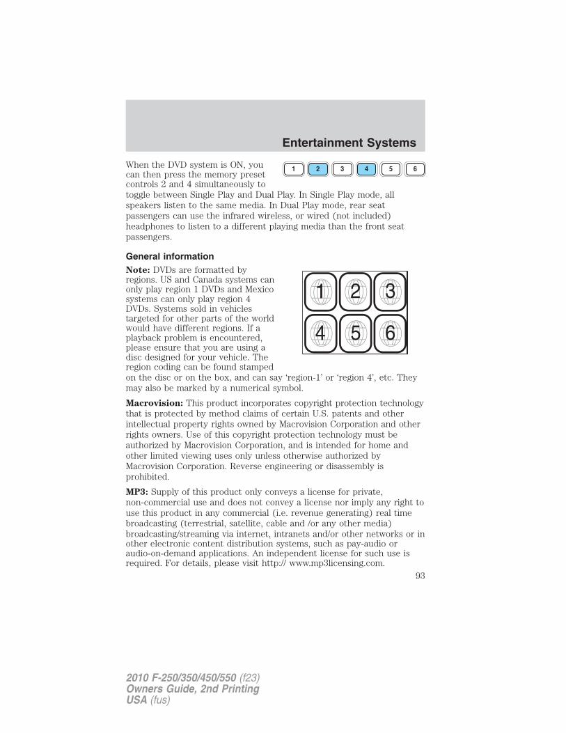
When the DVD system is ON, youcan then press the memory presetcontrols 2 and 4 simultaneously totoggle between Single Play and Dual Play. In Single Play mode, allspeakers listen to the same media. In Dual Play mode, rear seatpassengers can use the infrared wireless, or wired (not included)headphones to listen to a different playing media than the front seatpassengers.
General informationNote: DVDs are formatted byregions. US and Canada systems canonly play region 1 DVDs and Mexicosystems can only play region 4DVDs. Systems sold in vehiclestargeted for other parts of the worldwould have different regions. If aplayback problem is encountered,please ensure that you are using adisc designed for your vehicle. Theregion coding can be found stampedon the disc or on the box, and can say ‘region-1’ or ‘region 4’, etc. Theymay also be marked by a numerical symbol.
Macrovision: This product incorporates copyright protection technologythat is protected by method claims of certain U.S. patents and otherintellectual property rights owned by Macrovision Corporation and otherrights owners. Use of this copyright protection technology must beauthorized by Macrovision Corporation, and is intended for home andother limited viewing uses only unless otherwise authorized byMacrovision Corporation. Reverse engineering or disassembly isprohibited.
MP3: Supply of this product only conveys a license for private,non-commercial use and does not convey a license nor imply any right touse this product in any commercial (i.e. revenue generating) real timebroadcasting (terrestrial, satellite, cable and /or any other media)broadcasting/streaming via internet, intranets and/or other networks or inother electronic content distribution systems, such as pay-audio oraudio-on-demand applications. An independent license for such use isrequired. For details, please visit http:// www.mp3licensing.com.
1 2 3 4 5 6
Entertainment Systems
93
2010 F-250/350/450/550 (f23)Owners Guide, 2nd PrintingUSA (fus)
Safety information
WARNING: Driving while distracted can result in loss of vehiclecontrol, accident and injury. Ford strongly recommends that
drivers use extreme caution when using any device that may take theirfocus off the road. The driver’s primary responsibility is the safeoperation of their vehicle. Only use cell phones and other devices notessential to the driving task when it is safe to do so.
Read all of the safety and operating instructions before operating thesystem and retain for future reference.
Do not attempt to service, repair or modify the Family EntertainmentSystem (FES). See your dealer.
Do not insert foreign objects into the DVD compartment.
WARNING: Do not leave children unattended in the vehicle anddo not let children operate the system while unsupervised. If
wired headphones or auxiliary systems are used, children may becomeentangled in the cords and seriously injure themselves.
WARNING: The front glass on the liquid crystal display (LCD)flip-down screen may break when hit with a hard surface. If the
glass breaks, do not touch the liquid crystalline material. In case ofcontact with skin, wash immediately with soap and water.
WARNING: The driver should not attempt to operate anyfunction of the DVD system while the vehicle is in motion. Give
full attention to driving and to the road. Pull off the road in a safeplace before inserting or extracting DVDs from the system. A remotecontrol is included in the system to allow the rear seat occupants tooperate the FES functions without distracting the driver.
Do not expose the liquid crystal display (LCD) flip-down screento direct sunlight or intensive ultraviolet rays for extensiveperiods of time. Ultraviolet rays deteriorate the liquid crystal.
Be sure to review User Manuals for video games and video gameequipment when used as auxiliary inputs for your Family EntertainmentSystem (FES).
Entertainment Systems
94
2010 F-250/350/450/550 (f23)Owners Guide, 2nd PrintingUSA (fus)
Do not operate video games or video equipment if the power cordsand/or cables are broken, split or damaged. Carefully place cords and/orcables where they will not be stepped on or interfere with the operationof seats and/or compartments.
Disconnect video games and video equipment power cords and/or cableswhen not in use.
Avoid touching auxiliary input jacks with your fingers. Do not blow onthem or allow them to get wet or dirty.
Do not clean any part of the DVD player with benzene, lacquer thinner,acetone, or any other solvent.
Federal Communication Commission (FCC) ComplianceChanges or modifications not approved by Ford Lincoln-Mercury couldvoid user’s authority to operate the equipment. This equipment has beentested and found to comply with the limits for a Class B digital device,pursuant to Part 15 of the FCC Rules. These limits are designed toprovide reasonable protection against harmful interference in aresidential installation. This equipment generates, uses and can radiateradio frequency energy and, if not installed and used in accordance withthe instructions, may cause harmful interference and radiocommunications.
However, there is no guarantee that interference will not occur in aparticular installation. If this equipment does cause harmful interferenceto radio or television reception, which can be determined by turning theequipment off and on, the user is encouraged to consult the dealer or anexperienced radio/TV technician for help.
Care and service of the DVD player
Environmental extremesDVD players which are subjected to harsh environmental conditions maybe damaged or perform at less than maximum capability. To avoid theseoutcomes, whenever possible avoid exposing your DVD player to:
• extremely hot or cold temperatures.
• direct sunlight.
• high humidity.
• a dusty environment.
• locations where strong magnetic fields are generated.
Entertainment Systems
95
2010 F-250/350/450/550 (f23)Owners Guide, 2nd PrintingUSA (fus)
Temperature extremesWhen the vehicle is parked under direct sunlight or in an extremely coldplace for a long period of time, wait until the cabin temperature of thevehicle is at normal temperature before operating the system.
Humidity and moisture condensationMoisture in the air will condense in the DVD player under extremelyhumid conditions or when moving from a cold place to a warm one.Moisture condensation may cause damage to the DVD and/or player. Ifmoisture condensation occurs, do not insert a CD or DVD into theplayer. If one is already in the player, remove it. Turn the DVD player ONto dry the moisture before inserting a DVD. This could take an hour ormore.
Foreign substancesExercise care to prevent dirt and foreign objects from entering the DVDplayer compartment. Be especially careful not to spill liquids of any kindonto the media controls or into the system. If liquid is accidentallyspilled onto the system, immediately turn the system OFF and consult aqualified service technician.
Cleaning the liquid crystal display (LCD) flip-down screenClean the display screen by applying a small amount of water or anyammonia-based household glass cleaner directly to a soft cloth. Rub thescreen gently until the dust, dirt or fingerprints are removed. Do notspray the screen directly with water or glass cleaning solvents. Oversprayfrom these fluids could drip down into the internal electronics of thescreen and cause damage. Do not apply excessive pressure whilecleaning the screen.
Cleaning DVD and CD discsInspect all discs for contamination before playing. If necessary, cleandiscs only with an approved DVD and CD cleaner and wipe from thecenter out to the edge. Do not use circular motion.
Entertainment Systems
96
2010 F-250/350/450/550 (f23)Owners Guide, 2nd PrintingUSA (fus)
Compatibility with aftermarket audio systems(headphone only mode)When the Family Entertainment System (FES) detects that the originalradio supplied by Ford Motor Company has been removed from thevehicle, the FES will work in a state referred to as “Headphone OnlyMode.” This mode allows the FES to operate as a standalone system,without interface to the radio.
While operating in Headphone Only Mode, the system will have limitedfunctionality.
• The system will only output audio to the headphones. It will not becapable of providing audio to the speakers.
• The available sources in FES Headphone Only Mode are DVD-DISCand DVD-AUX, regardless of headphone channel (A or B).
• When a disc is inserted into the FES while in Headphone Only Mode,both headphone channels (A and B) will be connected to FES-DISC.
NAVIGATION SYSTEM (IF EQUIPPED)Your vehicle may be equipped with a navigation system. Refer to theNavigation System supplement for further information.
SYNC� (IF EQUIPPED)Your vehicle may be equipped with SYNC�, a hands-free communicationsand entertainment system with special phone and media features. Formore information, please refer to the SYNC� supplement or to theSYNC� section in the Navigation System supplement (if equipped).
Entertainment Systems
97
2010 F-250/350/450/550 (f23)Owners Guide, 2nd PrintingUSA (fus)
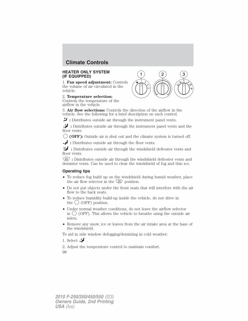
HEATER ONLY SYSTEM(IF EQUIPPED)1. Fan speed adjustment: Controlsthe volume of air circulated in thevehicle.
2. Temperature selection:Controls the temperature of theairflow in the vehicle.3. Air flow selections: Controls the direction of the airflow in thevehicle. See the following for a brief description on each control.
: Distributes outside air through the instrument panel vents.
: Distributes outside air through the instrument panel vents and thefloor vents.
(OFF): Outside air is shut out and the climate system is turned off.
: Distributes outside air through the floor vents.
: Distributes outside air through the windshield defroster vents andfloor vents.
: Distributes outside air through the windshield defroster vents anddemister vents. Can be used to clear the windshield of fog and thin ice.
Operating tips• To reduce fog build up on the windshield during humid weather, place
the air flow selector in the position.
• Do not put objects under the front seats that will interfere with the airflow to the back seats.
• To reduce humidity build-up inside the vehicle, do not drive inthe (OFF) position.
• Under normal weather conditions, do not leave the airflow selectorin (OFF). This allows the vehicle to breathe using the outside airinlets.
• Remove any snow, ice or leaves from the air intake area at the base ofthe windshield.
To aid in side window defogging/demisting in cold weather:
1. Select .
2. Adjust the temperature control to maintain comfort.
Climate Controls
98
2010 F-250/350/450/550 (f23)Owners Guide, 2nd PrintingUSA (fus)
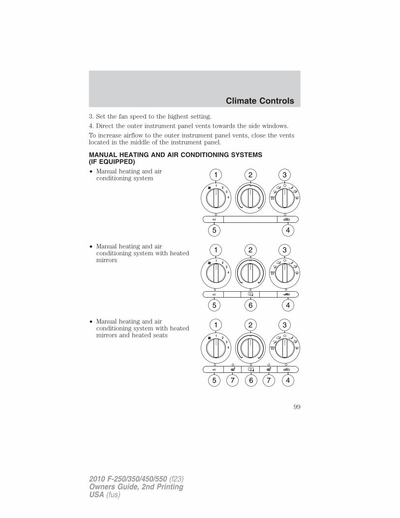
3. Set the fan speed to the highest setting.
4. Direct the outer instrument panel vents towards the side windows.
To increase airflow to the outer instrument panel vents, close the ventslocated in the middle of the instrument panel.
MANUAL HEATING AND AIR CONDITIONING SYSTEMS(IF EQUIPPED)• Manual heating and air
conditioning system
• Manual heating and airconditioning system with heatedmirrors
• Manual heating and airconditioning system with heatedmirrors and heated seats
Climate Controls
99
2010 F-250/350/450/550 (f23)Owners Guide, 2nd PrintingUSA (fus)
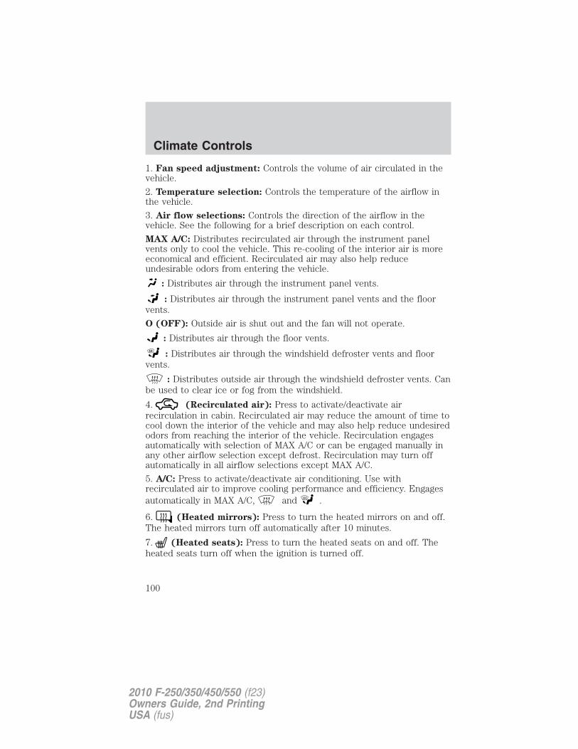
1. Fan speed adjustment: Controls the volume of air circulated in thevehicle.
2. Temperature selection: Controls the temperature of the airflow inthe vehicle.
3. Air flow selections: Controls the direction of the airflow in thevehicle. See the following for a brief description on each control.
MAX A/C: Distributes recirculated air through the instrument panelvents only to cool the vehicle. This re-cooling of the interior air is moreeconomical and efficient. Recirculated air may also help reduceundesirable odors from entering the vehicle.
: Distributes air through the instrument panel vents.
: Distributes air through the instrument panel vents and the floorvents.
O (OFF): Outside air is shut out and the fan will not operate.
: Distributes air through the floor vents.
: Distributes air through the windshield defroster vents and floorvents.
: Distributes outside air through the windshield defroster vents. Canbe used to clear ice or fog from the windshield.
4. (Recirculated air): Press to activate/deactivate airrecirculation in cabin. Recirculated air may reduce the amount of time tocool down the interior of the vehicle and may also help reduce undesiredodors from reaching the interior of the vehicle. Recirculation engagesautomatically with selection of MAX A/C or can be engaged manually inany other airflow selection except defrost. Recirculation may turn offautomatically in all airflow selections except MAX A/C.
5. A/C: Press to activate/deactivate air conditioning. Use withrecirculated air to improve cooling performance and efficiency. Engagesautomatically in MAX A/C, and .
6. (Heated mirrors): Press to turn the heated mirrors on and off.The heated mirrors turn off automatically after 10 minutes.
7. (Heated seats): Press to turn the heated seats on and off. Theheated seats turn off when the ignition is turned off.
Climate Controls
100
2010 F-250/350/450/550 (f23)Owners Guide, 2nd PrintingUSA (fus)
Operating tips
• To reduce fog build up on the windshield during humid weather, placethe air flow selector in the position.
• To reduce humidity build up inside the vehicle, do not drive with theair flow selector in the O (Off) position.
• Do not put objects under the front seats that will interfere with theairflow to the rear seats.
• Remove any snow, ice or leaves from the air intake area at the base ofthe windshield.
• To improve the A/C cool down, drive with the windows slightly openfor 2–3 minutes after start up or until the vehicle has been “aired out.”
During extreme high ambient temperatures when idling stationary forextended periods of time in gear, it is recommended to run the A/C inthe MAX A/C position, reduce blower fan speed from the highest settingand put the vehicle’s transmission into the P (PARK) gear position(automatic transmission only) to continue to receive cool air from yourA/C system.
For maximum cooling performance in MAX A/C mode:
1. Move the temperature control to the coolest setting.
2. Set the fan to the highest speed initially, then adjust in order tomaintain comfort.
To aid in side window defogging and demisting in cold weather:
1. Select .
2. Select A/C.
3. Set the temperature control to maintain comfort.
4. Set the fan speed to highest setting.
5. Direct the outer instrument panel vents towards the side windows.
Climate Controls
101
2010 F-250/350/450/550 (f23)Owners Guide, 2nd PrintingUSA (fus)
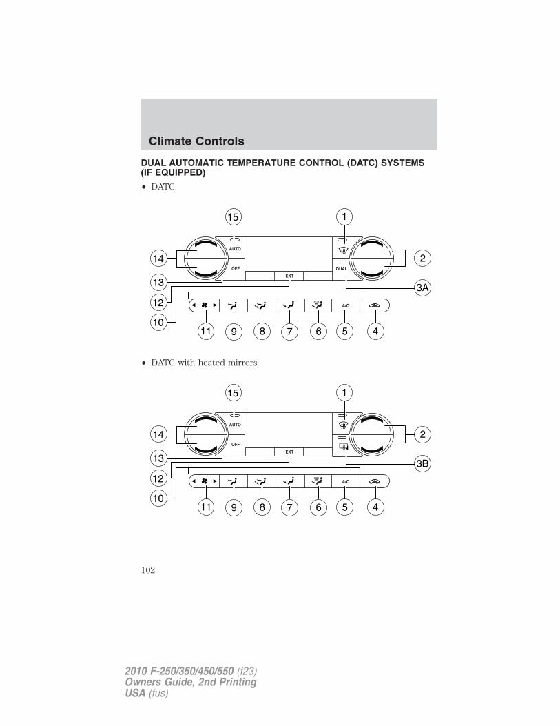
DUAL AUTOMATIC TEMPERATURE CONTROL (DATC) SYSTEMS(IF EQUIPPED)
• DATC
• DATC with heated mirrors
Climate Controls
102
2010 F-250/350/450/550 (f23)Owners Guide, 2nd PrintingUSA (fus)
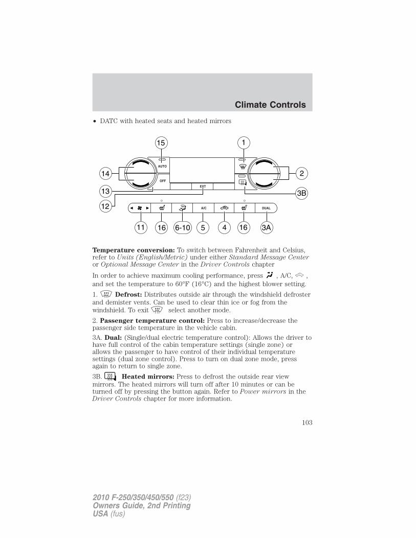
• DATC with heated seats and heated mirrors
Temperature conversion: To switch between Fahrenheit and Celsius,refer to Units (English/Metric) under either Standard Message Centeror Optional Message Center in the Driver Controls chapter
In order to achieve maximum cooling performance, press , A/C, ,and set the temperature to 60°F (16°C) and the highest blower setting.
1. Defrost: Distributes outside air through the windshield defrosterand demister vents. Can be used to clear thin ice or fog from thewindshield. To exit select another mode.
2. Passenger temperature control: Press to increase/decrease thepassenger side temperature in the vehicle cabin.
3A. Dual: (Single/dual electric temperature control): Allows the driver tohave full control of the cabin temperature settings (single zone) orallows the passenger to have control of their individual temperaturesettings (dual zone control). Press to turn on dual zone mode, pressagain to return to single zone.
3B. Heated mirrors: Press to defrost the outside rear viewmirrors. The heated mirrors will turn off after 10 minutes or can beturned off by pressing the button again. Refer to Power mirrors in theDriver Controls chapter for more information.
Climate Controls
103
2010 F-250/350/450/550 (f23)Owners Guide, 2nd PrintingUSA (fus)
4. Recirculation control: Press to activate/deactivate airrecirculation in cabin. Recirculated air may reduce the amount of time tocool down the interior of the vehicle and may also help reduce undesiredodors from reaching the interior of the vehicle. Recirculation can beengaged manually in any other airflow selection except (defrost).Recirculation may turn off automatically in all airflow selections exceptMAX A/C.
5. A/C control: Press to activate/deactivate air conditioning. Use withrecirculated air to improve cooling performance and efficiency. Engagesautomatically in AUTO, (defrost) and (floor/defrost).
6. Manual override controls: Press this control to manually selectwhere you want the airflow directed. To return to full automatic control,press AUTO.
7. : Distributes air through the windshield defroster vents and floorvents.
8. : Distributes air through the floor vents.
9. : Distributes air through the instrument panel vents and the floorvents.
10. : Distributes air through the instrument panel vents.
11. Fan speed control: Press to manually increase or decrease thefan speed. To return to automatic fan operation, press AUTO.
12. EXT: Press to display outside temperature. Press again to displaycabin temperature settings.
13. OFF: Outside air is shut out and the fan will not operate.
14. Driver temperature control: Press to increase/decrease the driverside temperature in the vehicle cabin.
15. AUTO: To engage automatic temperature control, press AUTO andselect the desired temperature using the temperature control. Thesystem will automatically determine fan speed, airflow location, A/C onor off, and outside or recirculated air, to heat or cool the vehicle to reachthe desired temperature.
16. Heated seat controls: Press to turn the heated seats on and off.The heated seats turn off when the ignition is turned off.
Climate Controls
104
2010 F-250/350/450/550 (f23)Owners Guide, 2nd PrintingUSA (fus)
Operating tips• To reduce fog build up on the windshield during humid weather, place
the air flow selector in the position.
• To reduce humidity build up inside the vehicle, do not drive with thesystem off, or with recirculated air engaged and A/C off.
• Do not put objects under the front seats that will interfere with theairflow to the back seats.
• Remove any snow, ice or leaves from the air intake area at the base ofthe windshield.
• To improve the A/C cool down, drive with the windows slightly openfor 2-3 minutes after start up or until the vehicle has been “aired out”.
During extreme high ambient temperatures when idling stationary forextended periods of time in gear, it is recommended to run the A/C inthe max A/C position, reduce blower fan speed from the highest settingand put the vehicle’s transmission into the P (PARK) gear position(automatic transmission only) to continue to receive cool air from yourA/C system.
For maximum cooling performance (MAX A/C):
Automatic operation:
1. Press AUTO for full automatic operation.
2. Do not override A/C or (recirculated air).
3. Set the temperature to 60°F (16°C).
Override operation:
1. Select air distribution.
2. Select A/C and (recirculated air). Use (recirculated air) withA/C to provide colder airflow.
3. Set the temperature to 60°F (16°C).
4. Set highest fan speed initially, then adjust to maintain comfort.
Climate Controls
105
2010 F-250/350/450/550 (f23)Owners Guide, 2nd PrintingUSA (fus)
In (panel) or (panel/floor) modes:
1. Move temperature control to full cold.
2. Select A/C and (recirculated air). Use recirculated air with A/C toprovide colder airflow.
3. Set highest fan speed initially, then adjust to maintain comfort.
To aid in side window defogging/demisting in cold weather:
1. Select .
2. Select A/C.
3. Adjust the temperature control to maintain comfort.
4. Set the fan speed to the highest setting.
5. Direct the outer instrument panel vents towards the side windows.
To increase airflow to the outer instrument panel vents, close the ventslocated in the middle of the instrument panel.
Climate Controls
106
2010 F-250/350/450/550 (f23)Owners Guide, 2nd PrintingUSA (fus)
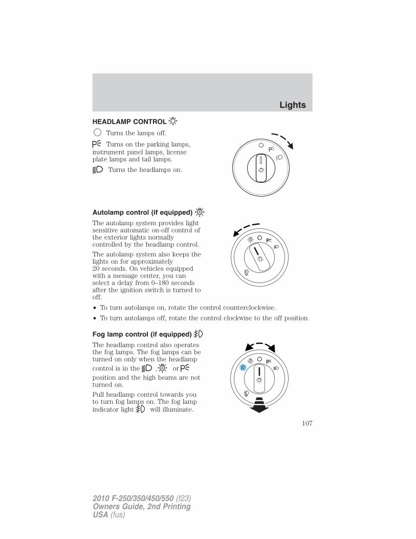
HEADLAMP CONTROL
Turns the lamps off.
Turns on the parking lamps,instrument panel lamps, licenseplate lamps and tail lamps.
Turns the headlamps on.
Autolamp control (if equipped)
The autolamp system provides lightsensitive automatic on-off control ofthe exterior lights normallycontrolled by the headlamp control.
The autolamp system also keeps thelights on for approximately20 seconds. On vehicles equippedwith a message center, you canselect a delay from 0–180 secondsafter the ignition switch is turned tooff.
• To turn autolamps on, rotate the control counterclockwise.
• To turn autolamps off, rotate the control clockwise to the off position.
Fog lamp control (if equipped)
The headlamp control also operatesthe fog lamps. The fog lamps can beturned on only when the headlampcontrol is in the , orposition and the high beams are notturned on.
Pull headlamp control towards youto turn fog lamps on. The fog lampindicator light will illuminate.
Lights
107
2010 F-250/350/450/550 (f23)Owners Guide, 2nd PrintingUSA (fus)
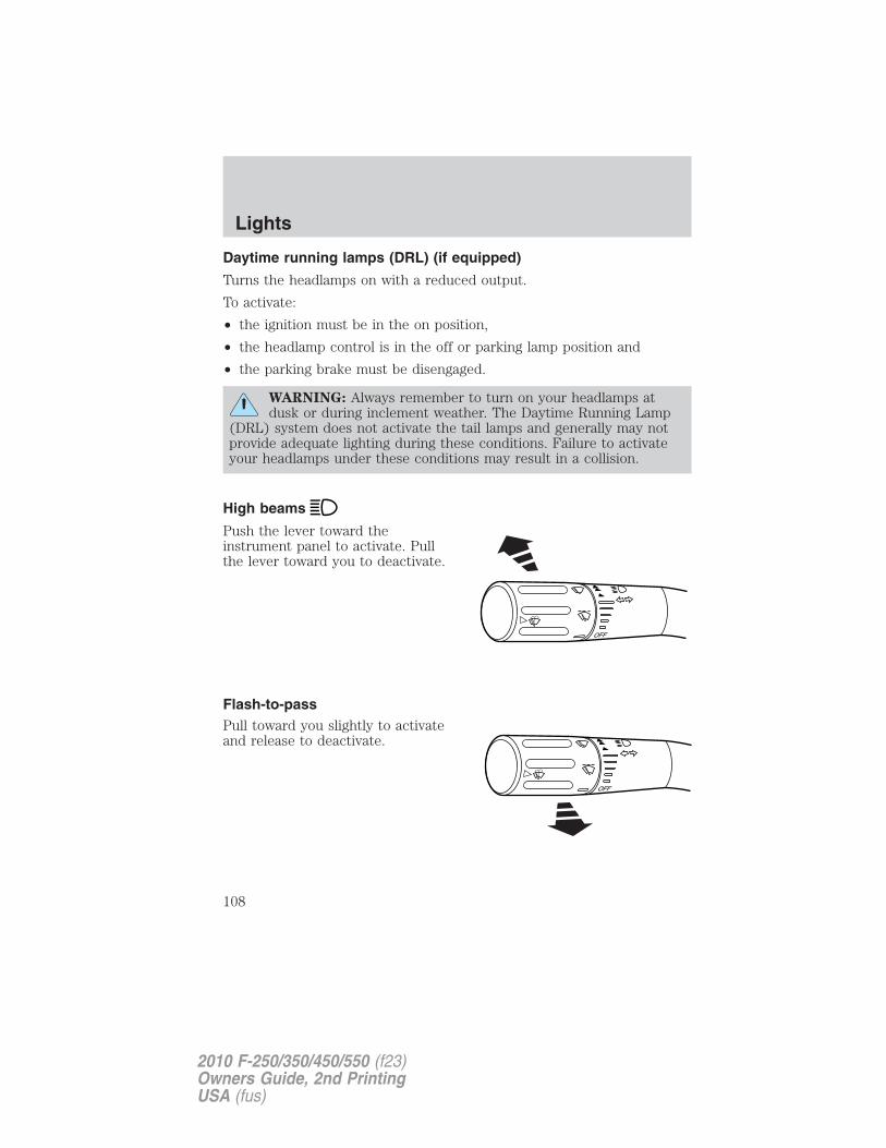
Daytime running lamps (DRL) (if equipped)
Turns the headlamps on with a reduced output.
To activate:
• the ignition must be in the on position,
• the headlamp control is in the off or parking lamp position and
• the parking brake must be disengaged.
WARNING: Always remember to turn on your headlamps atdusk or during inclement weather. The Daytime Running Lamp
(DRL) system does not activate the tail lamps and generally may notprovide adequate lighting during these conditions. Failure to activateyour headlamps under these conditions may result in a collision.
High beams
Push the lever toward theinstrument panel to activate. Pullthe lever toward you to deactivate.
Flash-to-passPull toward you slightly to activateand release to deactivate.
OFF
Lights
108
2010 F-250/350/450/550 (f23)Owners Guide, 2nd PrintingUSA (fus)
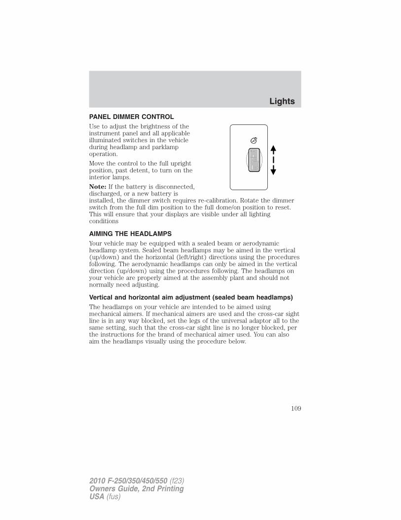
PANEL DIMMER CONTROLUse to adjust the brightness of theinstrument panel and all applicableilluminated switches in the vehicleduring headlamp and parklampoperation.
Move the control to the full uprightposition, past detent, to turn on theinterior lamps.
Note: If the battery is disconnected,discharged, or a new battery isinstalled, the dimmer switch requires re-calibration. Rotate the dimmerswitch from the full dim position to the full dome/on position to reset.This will ensure that your displays are visible under all lightingconditions
AIMING THE HEADLAMPSYour vehicle may be equipped with a sealed beam or aerodynamicheadlamp system. Sealed beam headlamps may be aimed in the vertical(up/down) and the horizontal (left/right) directions using the proceduresfollowing. The aerodynamic headlamps can only be aimed in the verticaldirection (up/down) using the procedures following. The headlamps onyour vehicle are properly aimed at the assembly plant and should notnormally need adjusting.
Vertical and horizontal aim adjustment (sealed beam headlamps)The headlamps on your vehicle are intended to be aimed usingmechanical aimers. If mechanical aimers are used and the cross-car sightline is in any way blocked, set the legs of the universal adaptor all to thesame setting, such that the cross-car sight line is no longer blocked, perthe instructions for the brand of mechanical aimer used. You can alsoaim the headlamps visually using the procedure below.
Lights
109
2010 F-250/350/450/550 (f23)Owners Guide, 2nd PrintingUSA (fus)
To adjust the headlamps:
1. Park your vehicle on a levelsurface about 25 feet (7.6 meters)away from a vertical plain surface(3). Check your headlamp alignmentat night or in a dark area so thatyou can see the headlamp beampattern.
• (1) 8 feet (2.4 meters)
• (2) Center height of lamp toground
• (3) 25 feet (7.6 meters)
• (4) Horizontal reference line
• (5) Center of headlamps
• (6) Center line of the vehicle
2. The center of the headlamp is marked either on the lens (a circle orcross marker) or on the bulb shield, internal to the lamp (mark orfeature). Measure the height from the center of your headlamp to theground (2) and mark an 8 foot (2.4 meter) long horizontal line on thewall or screen (1) at this height (masking tape works well).
3. Turn on the low beam headlampsand open the hood.
4. Locate the high intensity area ofthe beam pattern and place the topedge of the intensity zone even withthe horizontal reference line (4). Ifthe top edge of the high intensityarea is not even with the horizontalline, follow the next step to adjustit.
Lights
110
2010 F-250/350/450/550 (f23)Owners Guide, 2nd PrintingUSA (fus)
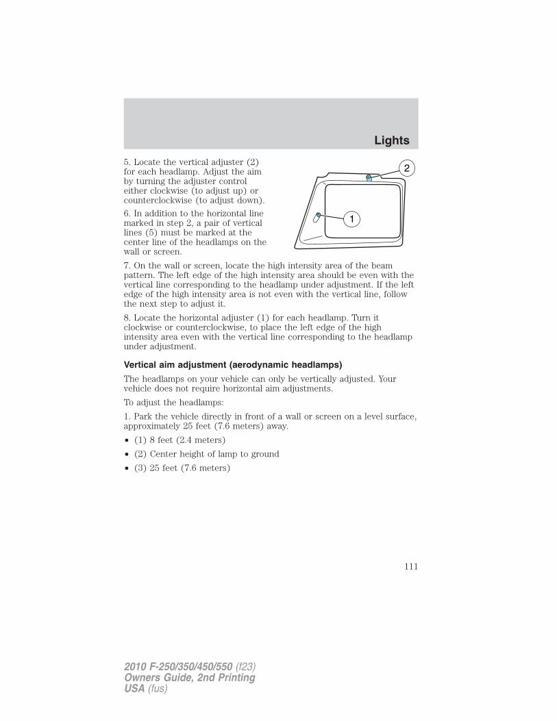
5. Locate the vertical adjuster (2)for each headlamp. Adjust the aimby turning the adjuster controleither clockwise (to adjust up) orcounterclockwise (to adjust down).
6. In addition to the horizontal linemarked in step 2, a pair of verticallines (5) must be marked at thecenter line of the headlamps on thewall or screen.
7. On the wall or screen, locate the high intensity area of the beampattern. The left edge of the high intensity area should be even with thevertical line corresponding to the headlamp under adjustment. If the leftedge of the high intensity area is not even with the vertical line, followthe next step to adjust it.
8. Locate the horizontal adjuster (1) for each headlamp. Turn itclockwise or counterclockwise, to place the left edge of the highintensity area even with the vertical line corresponding to the headlampunder adjustment.
Vertical aim adjustment (aerodynamic headlamps)
The headlamps on your vehicle can only be vertically adjusted. Yourvehicle does not require horizontal aim adjustments.
To adjust the headlamps:
1. Park the vehicle directly in front of a wall or screen on a level surface,approximately 25 feet (7.6 meters) away.
• (1) 8 feet (2.4 meters)
• (2) Center height of lamp to ground
• (3) 25 feet (7.6 meters)
Lights
111
2010 F-250/350/450/550 (f23)Owners Guide, 2nd PrintingUSA (fus)
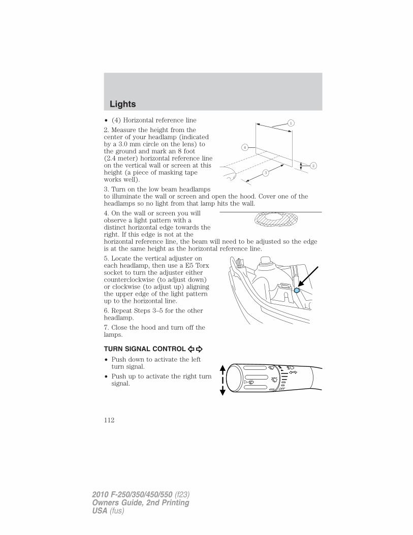
• (4) Horizontal reference line
2. Measure the height from thecenter of your headlamp (indicatedby a 3.0 mm circle on the lens) tothe ground and mark an 8 foot(2.4 meter) horizontal reference lineon the vertical wall or screen at thisheight (a piece of masking tapeworks well).
3. Turn on the low beam headlampsto illuminate the wall or screen and open the hood. Cover one of theheadlamps so no light from that lamp hits the wall.
4. On the wall or screen you willobserve a light pattern with adistinct horizontal edge towards theright. If this edge is not at thehorizontal reference line, the beam will need to be adjusted so the edgeis at the same height as the horizontal reference line.
5. Locate the vertical adjuster oneach headlamp, then use a E5 Torxsocket to turn the adjuster eithercounterclockwise (to adjust down)or clockwise (to adjust up) aligningthe upper edge of the light patternup to the horizontal line.
6. Repeat Steps 3–5 for the otherheadlamp.
7. Close the hood and turn off thelamps.
TURN SIGNAL CONTROL
• Push down to activate the leftturn signal.
• Push up to activate the right turnsignal.
Lights
112
2010 F-250/350/450/550 (f23)Owners Guide, 2nd PrintingUSA (fus)
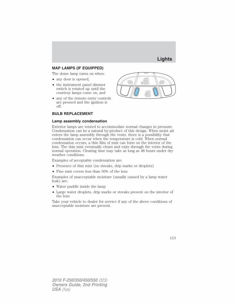
MAP LAMPS (IF EQUIPPED)The dome lamp turns on when:
• any door is opened,
• the instrument panel dimmerswitch is rotated up until thecourtesy lamps come on, and
• any of the remote entry controlsare pressed and the ignition isoff.
BULB REPLACEMENT
Lamp assembly condensationExterior lamps are vented to accommodate normal changes in pressure.Condensation can be a natural by-product of this design. When moist airenters the lamp assembly through the vents, there is a possibility thatcondensation can occur when the temperature is cold. When normalcondensation occurs, a thin film of mist can form on the interior of thelens. The thin mist eventually clears and exits through the vents duringnormal operation. Clearing time may take as long as 48 hours under dryweather conditions.
Examples of acceptable condensation are:
• Presence of thin mist (no streaks, drip marks or droplets)
• Fine mist covers less than 50% of the lens
Examples of unacceptable moisture (usually caused by a lamp waterleak) are:
• Water puddle inside the lamp
• Large water droplets, drip marks or streaks present on the interior ofthe lens
Take your vehicle to dealer for service if any of the above conditions ofunacceptable moisture are present.
Lights
113
2010 F-250/350/450/550 (f23)Owners Guide, 2nd PrintingUSA (fus)
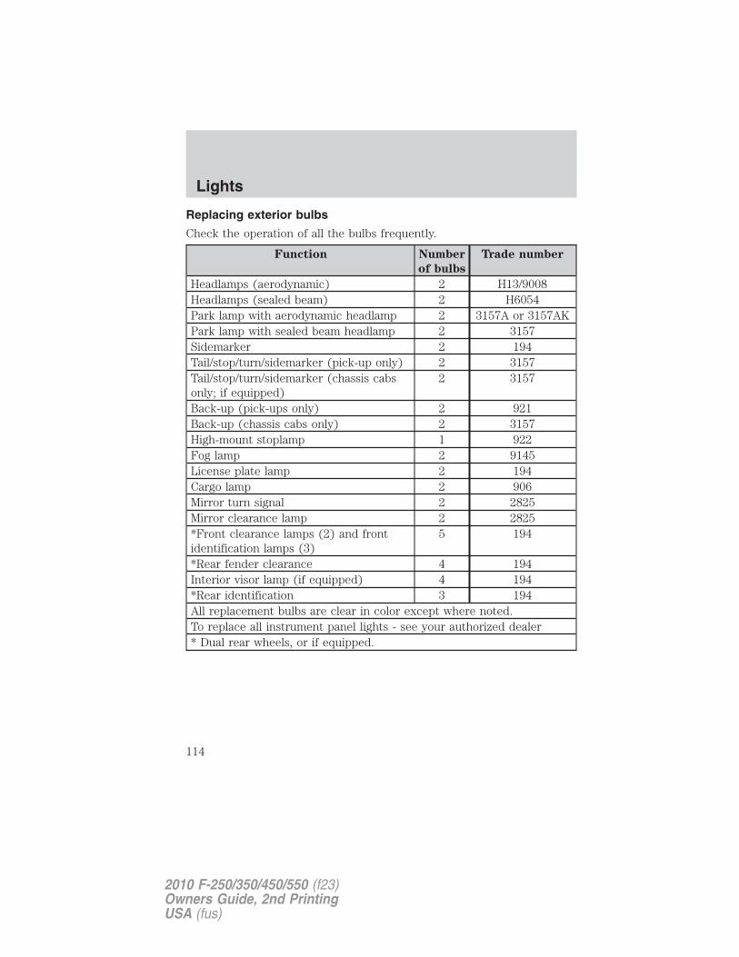
Replacing exterior bulbs
Check the operation of all the bulbs frequently.
Function Number
of bulbs
Trade number
Headlamps (aerodynamic) 2 H13/9008Headlamps (sealed beam) 2 H6054Park lamp with aerodynamic headlamp 2 3157A or 3157AKPark lamp with sealed beam headlamp 2 3157Sidemarker 2 194Tail/stop/turn/sidemarker (pick-up only) 2 3157Tail/stop/turn/sidemarker (chassis cabsonly; if equipped)
2 3157
Back-up (pick-ups only) 2 921Back-up (chassis cabs only) 2 3157High-mount stoplamp 1 922Fog lamp 2 9145License plate lamp 2 194Cargo lamp 2 906Mirror turn signal 2 2825Mirror clearance lamp 2 2825*Front clearance lamps (2) and frontidentification lamps (3)
5 194
*Rear fender clearance 4 194Interior visor lamp (if equipped) 4 194*Rear identification 3 194All replacement bulbs are clear in color except where noted.To replace all instrument panel lights - see your authorized dealer* Dual rear wheels, or if equipped.
Lights
114
2010 F-250/350/450/550 (f23)Owners Guide, 2nd PrintingUSA (fus)
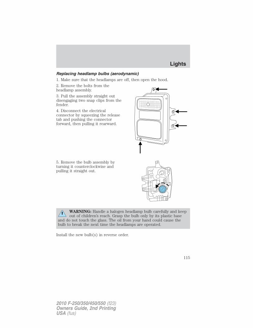
Replacing headlamp bulbs (aerodynamic)1. Make sure that the headlamps are off, then open the hood.
2. Remove the bolts from theheadlamp assembly.
3. Pull the assembly straight outdisengaging two snap clips from thefender.
4. Disconnect the electricalconnector by squeezing the releasetab and pushing the connectorforward, then pulling it rearward.
5. Remove the bulb assembly byturning it counterclockwise andpulling it straight out.
WARNING: Handle a halogen headlamp bulb carefully and keepout of children’s reach. Grasp the bulb only by its plastic base
and do not touch the glass. The oil from your hand could cause thebulb to break the next time the headlamps are operated.
Install the new bulb(s) in reverse order.
Lights
115
2010 F-250/350/450/550 (f23)Owners Guide, 2nd PrintingUSA (fus)
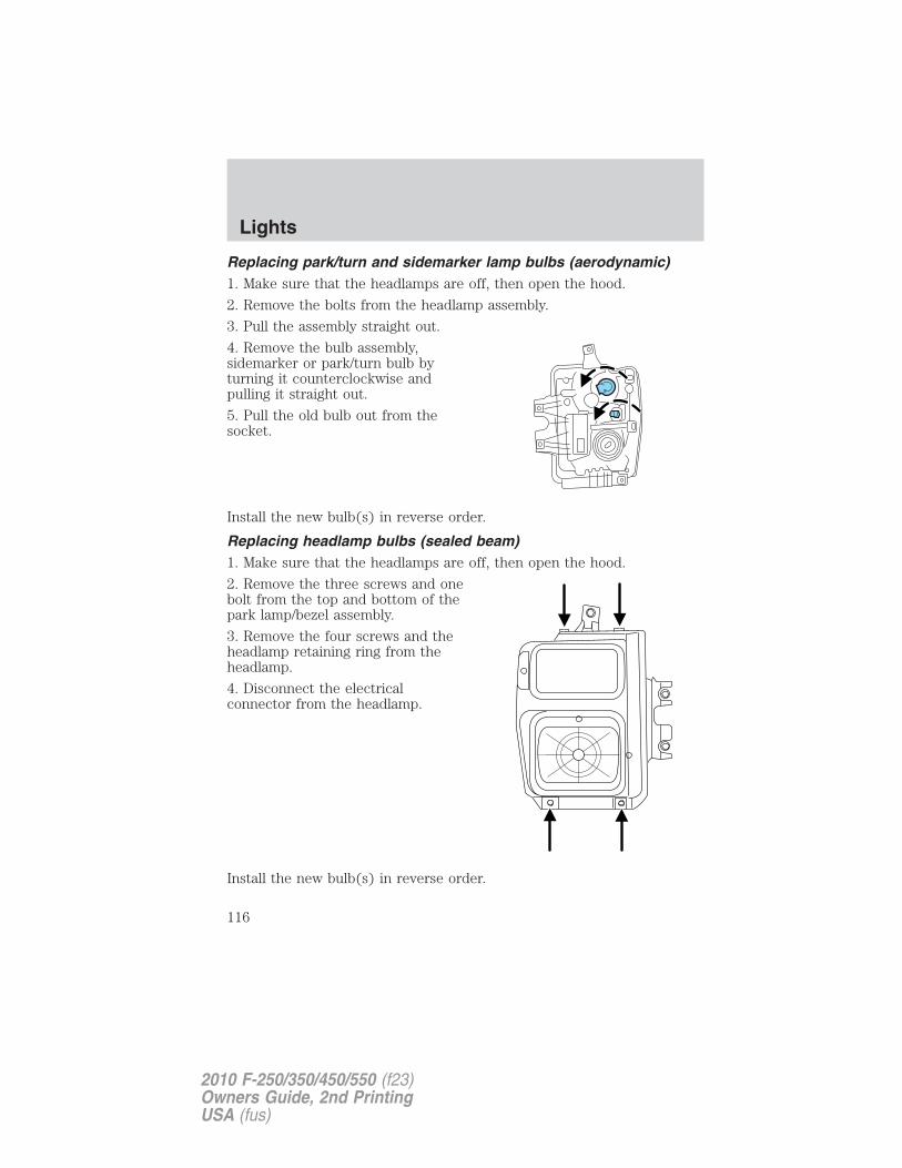
Replacing park/turn and sidemarker lamp bulbs (aerodynamic)1. Make sure that the headlamps are off, then open the hood.
2. Remove the bolts from the headlamp assembly.
3. Pull the assembly straight out.
4. Remove the bulb assembly,sidemarker or park/turn bulb byturning it counterclockwise andpulling it straight out.
5. Pull the old bulb out from thesocket.
Install the new bulb(s) in reverse order.
Replacing headlamp bulbs (sealed beam)1. Make sure that the headlamps are off, then open the hood.
2. Remove the three screws and onebolt from the top and bottom of thepark lamp/bezel assembly.
3. Remove the four screws and theheadlamp retaining ring from theheadlamp.
4. Disconnect the electricalconnector from the headlamp.
Install the new bulb(s) in reverse order.
Lights
116
2010 F-250/350/450/550 (f23)Owners Guide, 2nd PrintingUSA (fus)
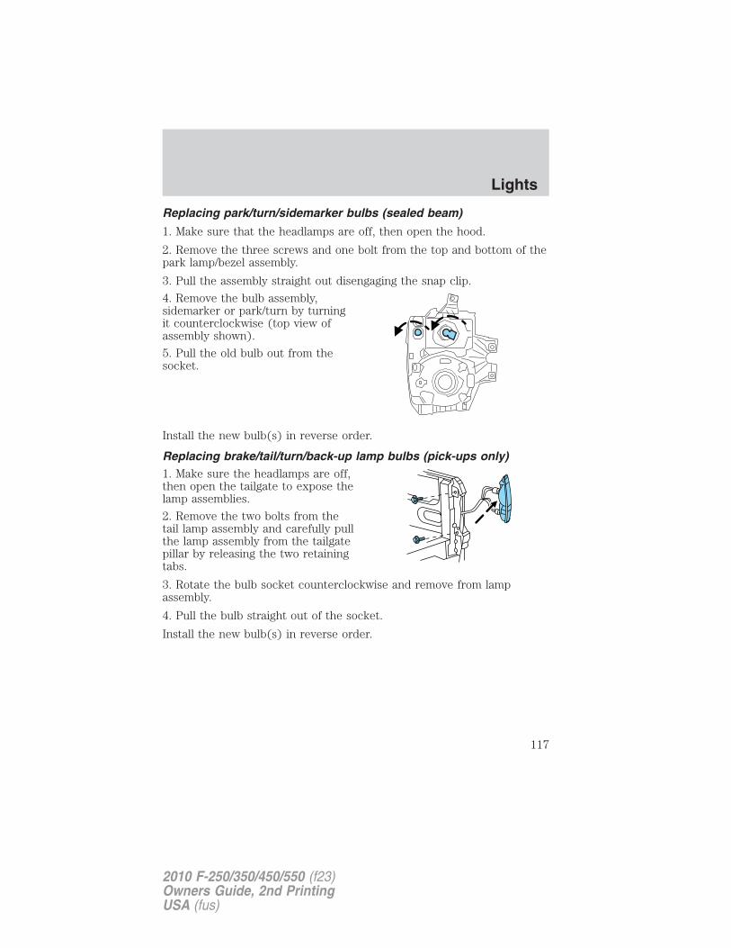
Replacing park/turn/sidemarker bulbs (sealed beam)
1. Make sure that the headlamps are off, then open the hood.
2. Remove the three screws and one bolt from the top and bottom of thepark lamp/bezel assembly.
3. Pull the assembly straight out disengaging the snap clip.
4. Remove the bulb assembly,sidemarker or park/turn by turningit counterclockwise (top view ofassembly shown).
5. Pull the old bulb out from thesocket.
Install the new bulb(s) in reverse order.
Replacing brake/tail/turn/back-up lamp bulbs (pick-ups only)1. Make sure the headlamps are off,then open the tailgate to expose thelamp assemblies.
2. Remove the two bolts from thetail lamp assembly and carefully pullthe lamp assembly from the tailgatepillar by releasing the two retainingtabs.
3. Rotate the bulb socket counterclockwise and remove from lampassembly.
4. Pull the bulb straight out of the socket.
Install the new bulb(s) in reverse order.
Lights
117
2010 F-250/350/450/550 (f23)Owners Guide, 2nd PrintingUSA (fus)
Replacing brake/tail/turn/back-up lamp bulbs (chassis cabs only)(if equipped)1. Make sure the headlamps are off.
2. Remove the four screws and thelamp lens from lamp assembly.
3. Carefully pull the bulb straightout of the socket and push in thenew bulb.
Replacing cargo lamp and high-mount brakelamp bulbs1. Make sure the headlamps are off.
2. Remove the screws and lampassembly from the vehicle as wiringpermits.
3. Remove the bulb socket byrotating it counterclockwise.
4. Pull the bulb straight out of thesocket.
Lights
118
2010 F-250/350/450/550 (f23)Owners Guide, 2nd PrintingUSA (fus)
Replacing front clearance and identification lamp bulbs1. Make sure the headlamps are off.
2. Remove the screw and lens fromthe lamp assembly.
3. Pull the bulb straight out of thesocket.
Install the bulb(s) in reverse order.
Replacing fog lamp bulbs (if equipped)1. Make sure the headlamps are off.
2. Remove the bulb socket from thefog lamp by turning itcounterclockwise.
3. Disconnect the electricalconnector from the fog lamp bulb.
Install the new bulb(s) in reverse order.
Replacing license plate lamp bulbsThe license plate bulbs are locatedbehind the rear bumper. To changethe license plate lamp bulbs:
1. Reach behind the rear bumper tolocate the bulb.
2. Twist the bulb socketcounterclockwise and carefully pullto remove it from the lampassembly.
3. Pull out the old bulb from thesocket and push in the new bulb.
4. Install the bulb socket in lamp assembly by turning it clockwise.
Lights
119
2010 F-250/350/450/550 (f23)Owners Guide, 2nd PrintingUSA (fus)
MULTI-FUNCTION LEVERWindshield wiper: Rotate the endof the control away from you toincrease the speed of the wipers;rotate towards you to decrease thespeed of the wipers.
Speed dependent wipers: When the wiper control is set on theintermittent settings, the speed of the wipers will automatically adjustwith the vehicle speed. The faster your vehicle is travelling the faster thewipers will go.
Windshield washer: Press the endof the stalk:
• briefly: causes a single swipe ofthe wipers without washer fluid.
• a quick press and hold: thewipers will swipe three times withwasher fluid.
• a long press and hold: the wipersand washer fluid will be activatedfor up to 10 seconds.
Courtesy wipe feature: One extra wipe will occur a few seconds afterwashing the front window to clear any excess washer fluid remaining onthe windshield.Note: Do not operate the washer when the washer reservoir is empty.This may cause the washer pump to overheat. Check the washer fluidlevel frequently. Do not operate the wipers when the windshield is dry.This may scratch the glass, damage the wiper blades and cause the wipermotor to burn out. Before operating the wiper on a dry windshield,always use the windshield washer. In freezing weather, be sure the wiperblades are not frozen to the windshield before operating the wipers.Windshield wiper rainlamp feature (if equipped with Autolamp)When the windshield wipers are turned on during daylight, and theheadlamp control is in the autolamp position, the exterior lamps will turnon after a brief delay and will remain on until the wipers are turned off.
Driver Controls
120
2010 F-250/350/450/550 (f23)Owners Guide, 2nd PrintingUSA (fus)
TILT STEERING WHEEL1. Pull and hold the steering wheelrelease control toward you.
2. Move the steering up or downuntil you find the desired location.
3. Release the steering wheelrelease control. This will lock thesteering wheel in position.
WARNING: Never adjust the steering column when the vehicleis moving.
ILLUMINATED VISOR MIRROR (IF EQUIPPED)Lift the mirror cover to turn on thevisor mirror lamp.
OVERHEAD CONSOLE (IF EQUIPPED)
The appearance of your vehicle’s overhead console will vary according toyour option package. If your vehicle is equipped with a moon roof, referto Moon roof later in this chapter for information on its operation.
Driver Controls
121
2010 F-250/350/450/550 (f23)Owners Guide, 2nd PrintingUSA (fus)
Storage compartment (if equipped)Press the release on the door toopen the storage compartment.
The storage compartment may beused to secure sunglasses or asimilar object and the front tab canbe used for holding tickets, paper,envelopes, etc. The front bin may beused to store small objects.
CENTER CONSOLE (IF EQUIPPED)
Your vehicle may be equipped with a variety of console features. Theseinclude:
• Utility compartment withcassette/CD holder
• Coin holder
• Pen holder
• Writing surface
• A power point inside the utilitycompartment and on the rear ofthe console
• Laptop storage
• Hanging file folder supports
• Rear cupholders (Crew Cab only)
WARNING: Use only soft cups in the cupholder. Hard objectscan injure you in a collision.
Center console/under-seat storage – Cabela’s Edition (if equipped)
Your vehicle may be equipped with a lockable compartment in the centerconsole and a lockable storage area under the rear seats.
Driver Controls
122
2010 F-250/350/450/550 (f23)Owners Guide, 2nd PrintingUSA (fus)
Center console storage
Use the vehicle’s ignition key tolock/unlock the compartment.
Under-seat storage
Flip the rear seat cushion up toaccess the rear under-seat storagearea. See Seating in the Seatingand Safety Restraints chapter formore information.
Use the vehicle’s ignition key tolock/unlock the compartment.Release the lid latches to open thestorage area.
AUXILIARY POWER POINT (12VDC)Power outlets are designed for accessory plugs only. Do not insertany other object in the power outlet for this will damage theoutlet and blow the fuse. Do not hang any type of accessory oraccessory bracket from the plug. Improper use of the poweroutlet can cause damage not covered by your warranty.
Auxiliary power points can be found in the following locations:
• On the instrument panel
Driver Controls
123
2010 F-250/350/450/550 (f23)Owners Guide, 2nd PrintingUSA (fus)
• On the rear of the center console (if equipped) (SuperCab and CrewCab models)
Do not use the power point for operating the cigarette lighter element (ifequipped).To prevent the fuse from being blown, do not use the power point(s)over the vehicle capacity of 12 VDC/180W. If the power point or cigarlighter socket is not working, a fuse may have blown. Refer to Fuses andrelays in the Roadside Emergencies chapter for information onchecking and replacing fuses.To have full capacity usage of your power point, the engine is required tobe running to avoid unintentional discharge of the battery. To preventthe battery from being discharged:• do not use the power point longer than necessary when the engine is
not running,• do not leave battery chargers, video game adapters, computers and
other devices plugged in overnight or when the vehicle is parked forextended periods.
Always keep the power point caps closed when not being used.POWER WINDOWS (IF EQUIPPED)
WARNING: Do not leave children unattended in the vehicle anddo not let children play with the power windows. They may
seriously injure themselves.
WARNING: When closing the power windows, you should verifythey are free of obstructions and ensure that children and/or
pets are not in the proximity of the window openings.
Press and pull the window switchesto open and close windows.
• Press down (to the first detent)and hold the switch to open.
• Pull up (to the first detent) andhold the switch to close.
Rear Window Buffeting: When one or both of the rear windows areopen, the vehicle may demonstrate a wind throb or buffeting noise. Thisnoise can be alleviated by lowering a front window approximately two tothree inches.
Driver Controls
124
2010 F-250/350/450/550 (f23)Owners Guide, 2nd PrintingUSA (fus)
One-touch downAllows the driver’s window to openfully without holding the controldown. Press the switch completelydown to the second detent andrelease quickly. The window willopen fully. Momentarily press theswitch to any position to stop thewindow operation.
Window lock (if equipped)The window lock feature allows onlythe driver to operate the powerwindows.
To lock out all the window controls(except for the driver’s) press theright side of the control. Press theleft side to restore the windowcontrols.
Power rear slider window (if equipped)
WARNING: Do not leave children unattended in the vehicle anddo not let children play with the power windows. They may
seriously injure themselves.
WARNING: When closing the power windows, you should verifythey are free of obstructions and ensure that children and/or
pets are not in the proximity of the window openings.
If your vehicle is equipped with apower rear slide window, the switchis located on the instrument panelbehind the right-hand side of thesteering wheel.
• Press the right side of the controlto open the window.
• Pull the right side of the controlto close the window.
Driver Controls
125
2010 F-250/350/450/550 (f23)Owners Guide, 2nd PrintingUSA (fus)
Accessory delay
With accessory delay, the window switches may be used for up to10 minutes after the ignition switch is turned to the off position or untileither front door is opened.
INTERIOR MIRROR
The interior rear view mirror has two pivot points on the support armwhich lets you adjust the mirror up or down and from side to side.
WARNING: Do not adjust the mirror while the vehicle is inmotion.
Automatic dimming interior rear view mirror (if equipped)
Your vehicle may be equipped with an interior rear view mirror whichhas an auto-dimming function. The electronic day/night mirror willchange from the normal (high reflective) state to the non-glare(darkened) state when bright lights (glare) reach the mirror. When themirror detects bright light from behind the vehicle, it will automaticallyadjust (darken) to minimize glare.
The mirror will automatically return to the normal state whenever thevehicle is placed in R (Reverse) to ensure a bright clear view whenbacking up.
Do not block the sensors on the front and back of the interiorrear view mirror since this may impair proper mirrorperformance.
Do not clean the housing or glass of any mirror with harshabrasives, fuel or other petroleum-based cleaning products.
Note: If equipped with a rearview camera system, a video image will bedisplayed in the mirror or the navigation system (if equipped) when thevehicle is put in R (Reverse). As you shift into any other gear from R(Reverse), the image will remain for a few seconds and then turn off.Refer to Rearview camera system in the Driving chapter.
Driver Controls
126
2010 F-250/350/450/550 (f23)Owners Guide, 2nd PrintingUSA (fus)
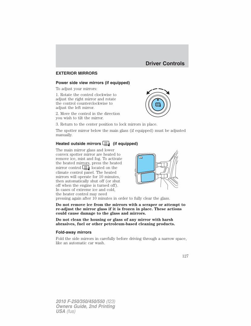
EXTERIOR MIRRORS
Power side view mirrors (if equipped)To adjust your mirrors:
1. Rotate the control clockwise toadjust the right mirror and rotatethe control counterclockwise toadjust the left mirror.
2. Move the control in the directionyou wish to tilt the mirror.
3. Return to the center position to lock mirrors in place.
The spotter mirror below the main glass (if equipped) must be adjustedmanually.
Heated outside mirrors (if equipped)
The main mirror glass and lowerconvex spotter mirror are heated toremove ice, mist and fog. To activatethe heated mirrors, press the heatedmirror control located on theclimate control panel. The heatedmirrors will operate for 10 minutes,then automatically shut off (or shutoff when the engine is turned off).In cases of extreme ice and cold,the heater control may needpressing again after 10 minutes in order to fully clear the glass.
Do not remove ice from the mirrors with a scraper or attempt tore-adjust the mirror glass if it is frozen in place. These actionscould cause damage to the glass and mirrors.
Do not clean the housing or glass of any mirror with harshabrasives, fuel or other petroleum-based cleaning products.
Fold-away mirrors
Fold the side mirrors in carefully before driving through a narrow space,like an automatic car wash.
Driver Controls
127
2010 F-250/350/450/550 (f23)Owners Guide, 2nd PrintingUSA (fus)
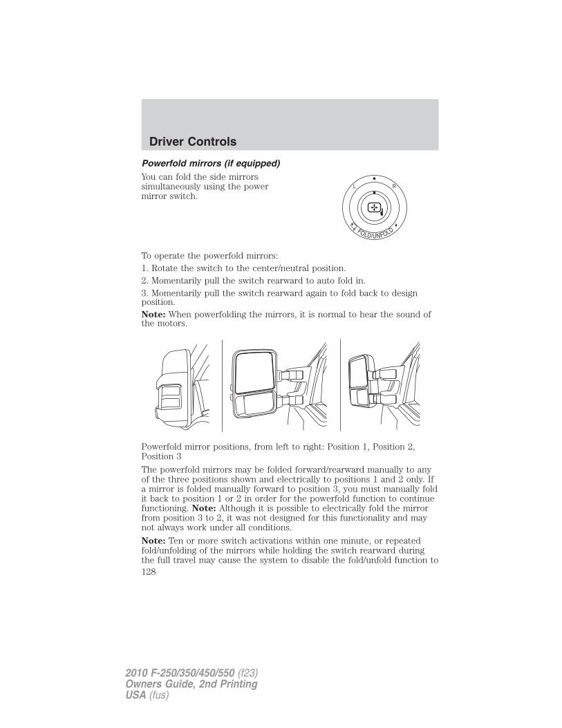
Powerfold mirrors (if equipped)You can fold the side mirrorssimultaneously using the powermirror switch.
To operate the powerfold mirrors:1. Rotate the switch to the center/neutral position.2. Momentarily pull the switch rearward to auto fold in.3. Momentarily pull the switch rearward again to fold back to designposition.Note: When powerfolding the mirrors, it is normal to hear the sound ofthe motors.
Powerfold mirror positions, from left to right: Position 1, Position 2,Position 3
The powerfold mirrors may be folded forward/rearward manually to anyof the three positions shown and electrically to positions 1 and 2 only. Ifa mirror is folded manually forward to position 3, you must manually foldit back to position 1 or 2 in order for the powerfold function to continuefunctioning. Note: Although it is possible to electrically fold the mirrorfrom position 3 to 2, it was not designed for this functionality and maynot always work under all conditions.
Note: Ten or more switch activations within one minute, or repeatedfold/unfolding of the mirrors while holding the switch rearward duringthe full travel may cause the system to disable the fold/unfold function to
Driver Controls
128
2010 F-250/350/450/550 (f23)Owners Guide, 2nd PrintingUSA (fus)
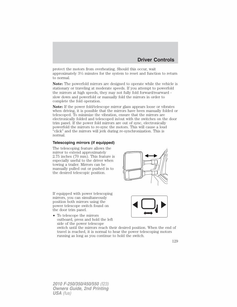
protect the motors from overheating. Should this occur, waitapproximately 31⁄2 minutes for the system to reset and function to returnto normal.
Note: The powerfold mirrors are designed to operate while the vehicle isstationary or traveling at moderate speeds. If you attempt to powerfoldthe mirrors at high speeds, they may not fully fold forward/rearward -slow down and powerfold or manually fold the mirrors in order tocomplete the fold operation.
Note: If the power fold/telescope mirror glass appears loose or vibrateswhen driving, it is possible that the mirrors have been manually folded ortelescoped. To minimize the vibration, ensure that the mirrors areelectronically folded and telescoped in/out with the switches on the doortrim panel. If the power fold mirrors are out of sync, electronicallypowerfold the mirrors to re-sync the motors. This will cause a loud“click” and the mirrors will jerk during re-synchronization. This isnormal.
Telescoping mirrors (if equipped)The telescoping feature allows themirror to extend approximately2.75 inches (70 mm). This feature isespecially useful to the driver whentowing a trailer. Mirrors can bemanually pulled out or pushed in tothe desired telescopic position.
If equipped with power telescopingmirrors, you can simultaneouslyposition both mirrors using thepower telescope switch found onthe door trim panel.
• To telescope the mirrorsoutboard, press and hold the leftside of the power telescopeswitch until the mirrors reach their desired position. When the end oftravel is reached, it is normal to hear the power telescoping motorsrunning as long as you continue to hold the switch.
Driver Controls
129
2010 F-250/350/450/550 (f23)Owners Guide, 2nd PrintingUSA (fus)
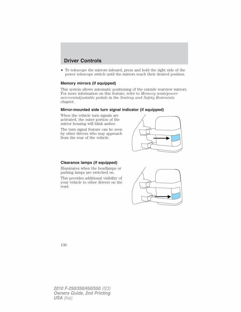
• To telescope the mirrors inboard, press and hold the right side of thepower telescope switch until the mirrors reach their desired position.
Memory mirrors (if equipped)
This system allows automatic positioning of the outside rearview mirrors.For more information on this feature, refer to Memory seats/powermirrors/adjustable pedals in the Seating and Safety Restraintschapter.
Mirror-mounted side turn signal indicator (if equipped)When the vehicle turn signals areactivated, the outer portion of themirror housing will blink amber.
The turn signal feature can be seenby other drivers who may approachfrom the rear of the vehicle.
Clearance lamps (if equipped)Illuminates when the headlamps orparking lamps are switched on.
This provides additional visibility ofyour vehicle to other drivers on theroad.
Driver Controls
130
2010 F-250/350/450/550 (f23)Owners Guide, 2nd PrintingUSA (fus)
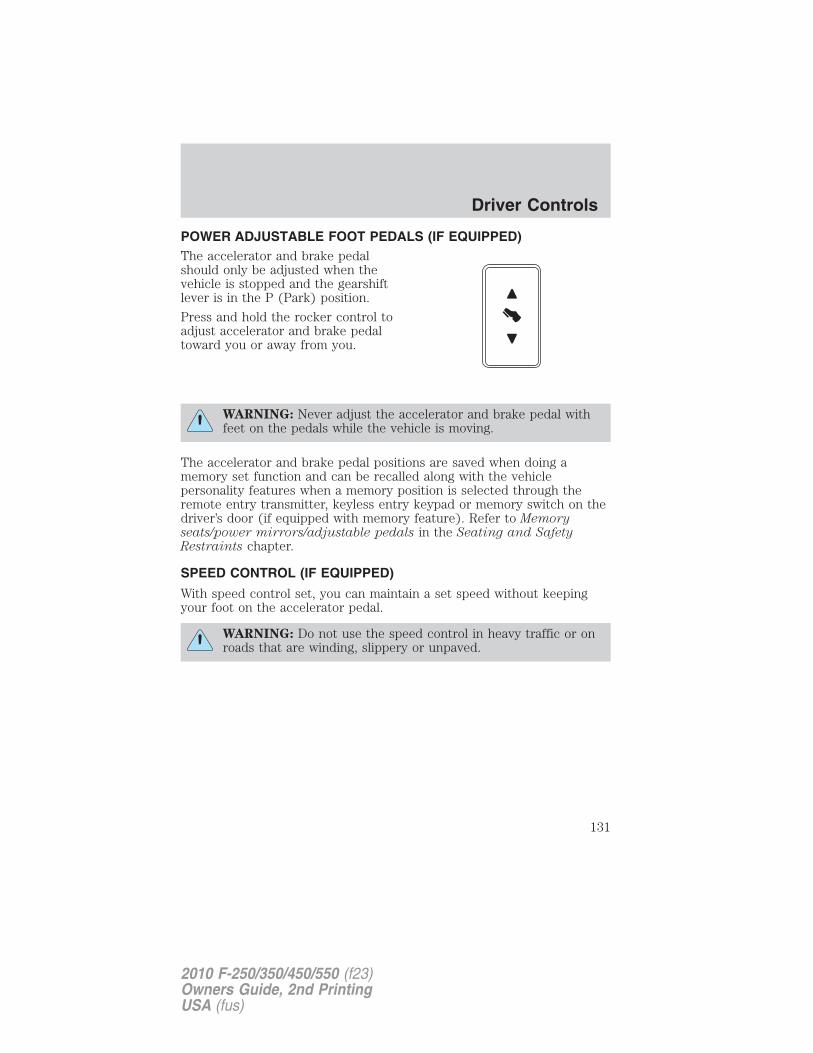
POWER ADJUSTABLE FOOT PEDALS (IF EQUIPPED)The accelerator and brake pedalshould only be adjusted when thevehicle is stopped and the gearshiftlever is in the P (Park) position.
Press and hold the rocker control toadjust accelerator and brake pedaltoward you or away from you.
WARNING: Never adjust the accelerator and brake pedal withfeet on the pedals while the vehicle is moving.
The accelerator and brake pedal positions are saved when doing amemory set function and can be recalled along with the vehiclepersonality features when a memory position is selected through theremote entry transmitter, keyless entry keypad or memory switch on thedriver’s door (if equipped with memory feature). Refer to Memoryseats/power mirrors/adjustable pedals in the Seating and SafetyRestraints chapter.
SPEED CONTROL (IF EQUIPPED)
With speed control set, you can maintain a set speed without keepingyour foot on the accelerator pedal.
WARNING: Do not use the speed control in heavy traffic or onroads that are winding, slippery or unpaved.
Driver Controls
131
2010 F-250/350/450/550 (f23)Owners Guide, 2nd PrintingUSA (fus)
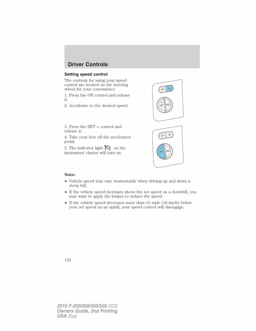
Setting speed controlThe controls for using your speedcontrol are located on the steeringwheel for your convenience.
1. Press the ON control and releaseit.
2. Accelerate to the desired speed.
3. Press the SET + control andrelease it.
4. Take your foot off the acceleratorpedal.
5. The indicator light on theinstrument cluster will turn on.
Note:
• Vehicle speed may vary momentarily when driving up and down asteep hill.
• If the vehicle speed increases above the set speed on a downhill, youmay want to apply the brakes to reduce the speed.
• If the vehicle speed decreases more than 10 mph (16 km/h) belowyour set speed on an uphill, your speed control will disengage.
Driver Controls
132
2010 F-250/350/450/550 (f23)Owners Guide, 2nd PrintingUSA (fus)
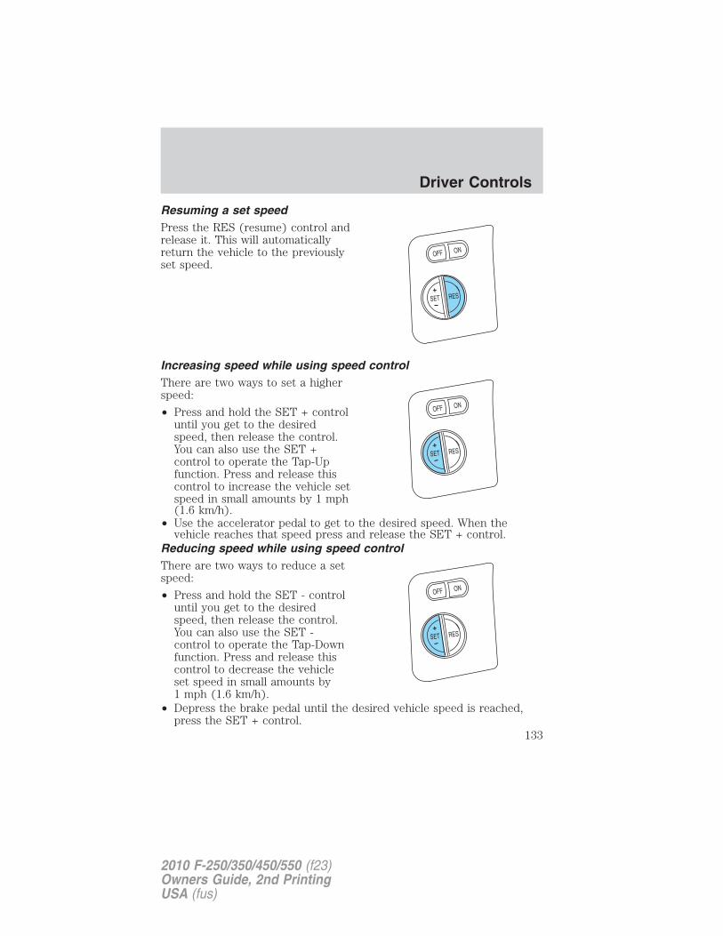
Resuming a set speedPress the RES (resume) control andrelease it. This will automaticallyreturn the vehicle to the previouslyset speed.
Increasing speed while using speed controlThere are two ways to set a higherspeed:
• Press and hold the SET + controluntil you get to the desiredspeed, then release the control.You can also use the SET +control to operate the Tap-Upfunction. Press and release thiscontrol to increase the vehicle setspeed in small amounts by 1 mph(1.6 km/h).
• Use the accelerator pedal to get to the desired speed. When thevehicle reaches that speed press and release the SET + control.
Reducing speed while using speed controlThere are two ways to reduce a setspeed:
• Press and hold the SET - controluntil you get to the desiredspeed, then release the control.You can also use the SET -control to operate the Tap-Downfunction. Press and release thiscontrol to decrease the vehicleset speed in small amounts by1 mph (1.6 km/h).
• Depress the brake pedal until the desired vehicle speed is reached,press the SET + control.
Driver Controls
133
2010 F-250/350/450/550 (f23)Owners Guide, 2nd PrintingUSA (fus)
Turning off speed control
There are two ways to turn off the speed control:
• Depress the brake pedal. This will not erase your vehicle’s previouslyset speed.
• Press the speed control OFFcontrol.
Note: When you turn off the speedcontrol or the ignition, your speedcontrol set speed memory is erased.
STEERING WHEEL CONTROLS (IF EQUIPPED)
These controls allow you to operate some radio and climate controlfeatures.
Audio control featuresPress MEDIA to select:
• AM, FM1, FM2
• CD (if equipped)
• DVD (if equipped)
• SAT1, SAT2 or SAT3 (SatelliteRadio mode, if equipped).
• LINE IN (Auxiliary input jack)
Driver Controls
134
2010 F-250/350/450/550 (f23)Owners Guide, 2nd PrintingUSA (fus)
In AM, FM1, or FM2 mode:
• Press SEEK toselect preset stations within theselected radio band or press andhold to select the next/previousradio frequency.
In Satellite radio mode (ifequipped):
• Press SEEK toadvance through preset channels or subscribed channels.
In CD mode:
• Press SEEK to select the next selection on the CD orpress and hold to forward or reverse the CD.
In any mode:
• Press VOL + or − to adjustvolume.
Navigation system hands freecontrol features (if equipped)
Press and hold VOICE briefly untilthe voice icon appears on thenavigation display to use the voicecommand feature.
Press VOICE to complete a voicecommand.
For further information on theNavigation system, refer to theNavigation System supplement.
Driver Controls
135
2010 F-250/350/450/550 (f23)Owners Guide, 2nd PrintingUSA (fus)
SYNC� system hands freecontrol feature (if equipped)
Press VOICE briefly until thevoice icon appears on the displayto use the voice command feature.You will hear a tone and LISTENINGwill appear in the radio display.Press and hold VOICE to exit voicecommand.
Press to activate phone mode oranswer a phone call. Press and hold to end call or exit phone mode.
Press to scroll through various menus and selections. PressOK to confirm your selection.
For further information on the SYNC� system, refer to the SYNC�supplement.
Navigation system/SYNC� handsfree control features (ifequipped)
Press VOICE briefly until thevoice icon appears on thenavigation display to use the voicecommand feature.
Press to activate phone mode oranswer a phone call. Press andhold to exit phone mode or endcall.
For further information on the Navigation system/SYNC� system, refer tothe Navigation System and SYNC� supplements.
Driver Controls
136
2010 F-250/350/450/550 (f23)Owners Guide, 2nd PrintingUSA (fus)
UPFITTER CONTROLS (IF EQUIPPED)Your vehicle may be equipped withthe Upfitter option package whichwill provide four switches, mountedin the center of the instrumentpanel, labeled AUX 1, AUX 2, AUX 3and AUX 4. These switches will onlyoperate while the ignition is in theon position, whether the engine isrunning or not. It is, however, recommended that the engine remainrunning to maintain battery charge when using the Upfitter switches forextended duration or higher current draws. (This is even more importantfor vehicles with diesel engines since the glow plugs are also drainingbattery power when the ignition key is in the on position.)
When switched on by the operator they provide 10 amps, 15 amps or30 amps of electrical battery power for a variety of personal orcommercial uses.
If your vehicle is equipped with this option, there will also be a relay boxlocated on the driver side end of the instrument panel. See yourauthorized dealer for service.
The relays are coded as shown inthe accompanying illustration.
RELAY1
RELAY2
RELAY3
RELAY4
Driver Controls
137
2010 F-250/350/450/550 (f23)Owners Guide, 2nd PrintingUSA (fus)
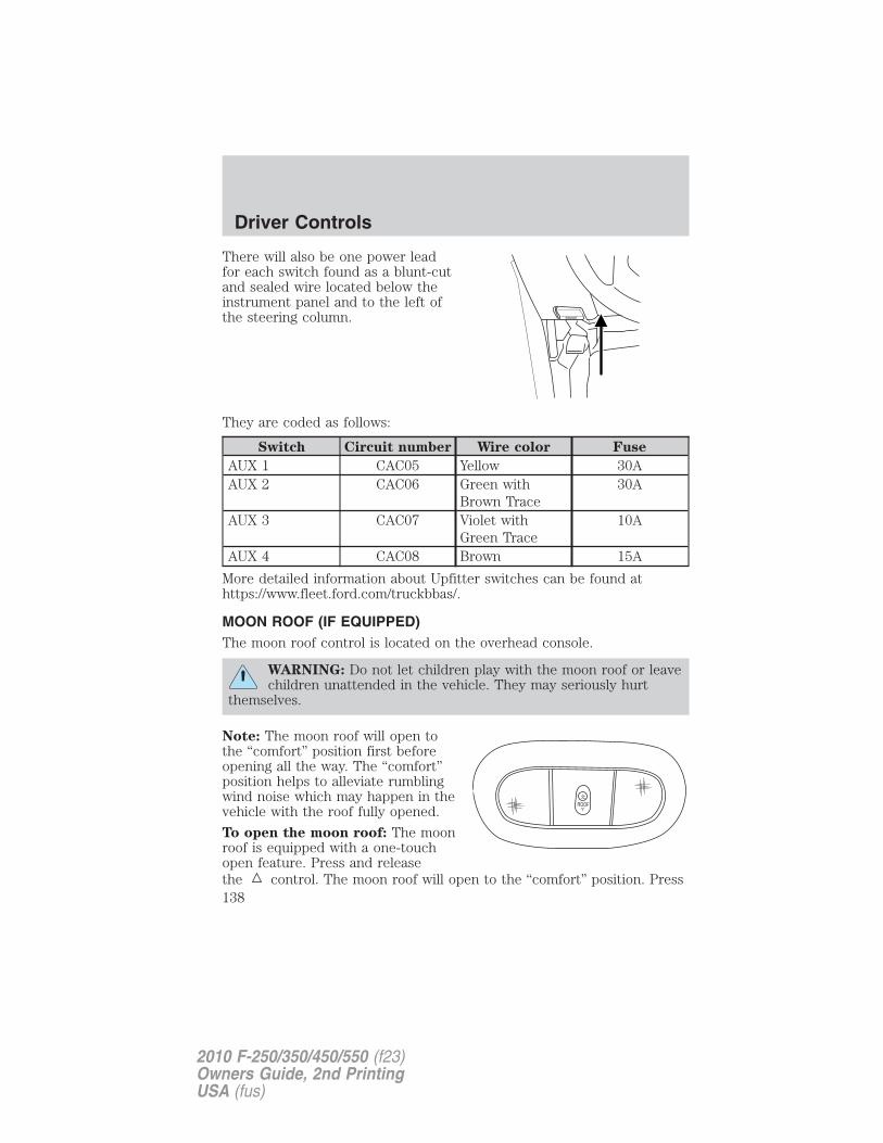
There will also be one power leadfor each switch found as a blunt-cutand sealed wire located below theinstrument panel and to the left ofthe steering column.
They are coded as follows:
Switch Circuit number Wire color Fuse
AUX 1 CAC05 Yellow 30AAUX 2 CAC06 Green with
Brown Trace30A
AUX 3 CAC07 Violet withGreen Trace
10A
AUX 4 CAC08 Brown 15A
More detailed information about Upfitter switches can be found athttps://www.fleet.ford.com/truckbbas/.
MOON ROOF (IF EQUIPPED)The moon roof control is located on the overhead console.
WARNING: Do not let children play with the moon roof or leavechildren unattended in the vehicle. They may seriously hurt
themselves.
Note: The moon roof will open tothe “comfort” position first beforeopening all the way. The “comfort”position helps to alleviate rumblingwind noise which may happen in thevehicle with the roof fully opened.
To open the moon roof: The moonroof is equipped with a one-touchopen feature. Press and releasethe control. The moon roof will open to the “comfort” position. Press
Driver Controls
138
2010 F-250/350/450/550 (f23)Owners Guide, 2nd PrintingUSA (fus)
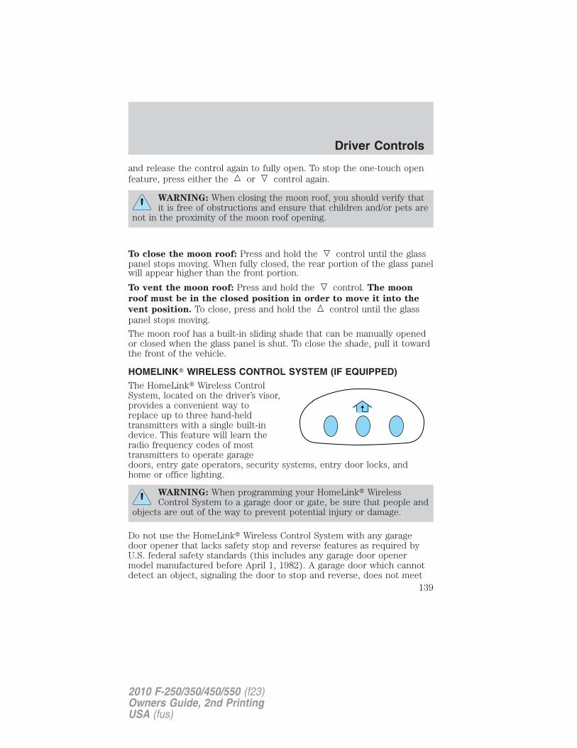
and release the control again to fully open. To stop the one-touch openfeature, press either the or control again.
WARNING: When closing the moon roof, you should verify thatit is free of obstructions and ensure that children and/or pets are
not in the proximity of the moon roof opening.
To close the moon roof: Press and hold the control until the glasspanel stops moving. When fully closed, the rear portion of the glass panelwill appear higher than the front portion.
To vent the moon roof: Press and hold the control. The moon
roof must be in the closed position in order to move it into the
vent position. To close, press and hold the control until the glasspanel stops moving.
The moon roof has a built-in sliding shade that can be manually openedor closed when the glass panel is shut. To close the shade, pull it towardthe front of the vehicle.
HOMELINK� WIRELESS CONTROL SYSTEM (IF EQUIPPED)The HomeLink� Wireless ControlSystem, located on the driver’s visor,provides a convenient way toreplace up to three hand-heldtransmitters with a single built-indevice. This feature will learn theradio frequency codes of mosttransmitters to operate garagedoors, entry gate operators, security systems, entry door locks, andhome or office lighting.
WARNING: When programming your HomeLink� WirelessControl System to a garage door or gate, be sure that people and
objects are out of the way to prevent potential injury or damage.
Do not use the HomeLink� Wireless Control System with any garagedoor opener that lacks safety stop and reverse features as required byU.S. federal safety standards (this includes any garage door openermodel manufactured before April 1, 1982). A garage door which cannotdetect an object, signaling the door to stop and reverse, does not meet
Driver Controls
139
2010 F-250/350/450/550 (f23)Owners Guide, 2nd PrintingUSA (fus)
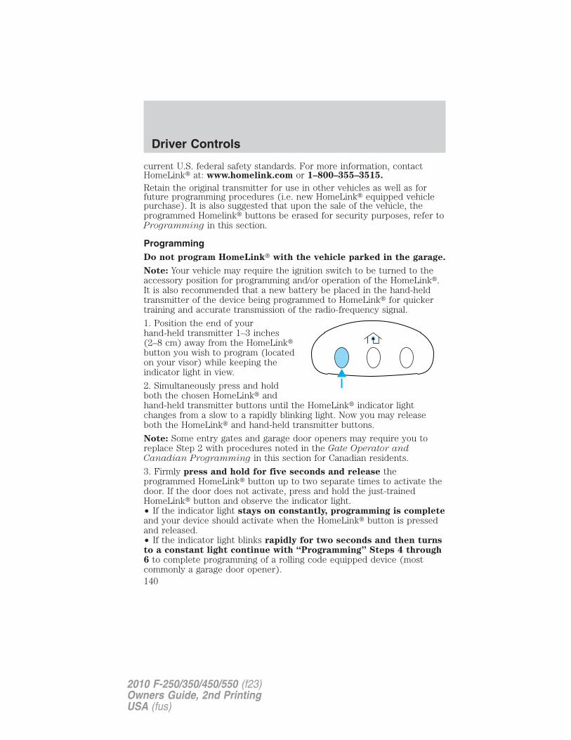
current U.S. federal safety standards. For more information, contactHomeLink� at: www.homelink.com or 1–800–355–3515.
Retain the original transmitter for use in other vehicles as well as forfuture programming procedures (i.e. new HomeLink� equipped vehiclepurchase). It is also suggested that upon the sale of the vehicle, theprogrammed Homelink� buttons be erased for security purposes, refer toProgramming in this section.
ProgrammingDo not program HomeLink� with the vehicle parked in the garage.
Note: Your vehicle may require the ignition switch to be turned to theaccessory position for programming and/or operation of the HomeLink�.It is also recommended that a new battery be placed in the hand-heldtransmitter of the device being programmed to HomeLink� for quickertraining and accurate transmission of the radio-frequency signal.
1. Position the end of yourhand-held transmitter 1–3 inches(2–8 cm) away from the HomeLink�button you wish to program (locatedon your visor) while keeping theindicator light in view.
2. Simultaneously press and holdboth the chosen HomeLink� andhand-held transmitter buttons until the HomeLink� indicator lightchanges from a slow to a rapidly blinking light. Now you may releaseboth the HomeLink� and hand-held transmitter buttons.
Note: Some entry gates and garage door openers may require you toreplace Step 2 with procedures noted in the Gate Operator andCanadian Programming in this section for Canadian residents.
3. Firmly press and hold for five seconds and release theprogrammed HomeLink� button up to two separate times to activate thedoor. If the door does not activate, press and hold the just-trainedHomeLink� button and observe the indicator light.• If the indicator light stays on constantly, programming is completeand your device should activate when the HomeLink� button is pressedand released.• If the indicator light blinks rapidly for two seconds and then turnsto a constant light continue with “Programming” Steps 4 through6 to complete programming of a rolling code equipped device (mostcommonly a garage door opener).
Driver Controls
140
2010 F-250/350/450/550 (f23)Owners Guide, 2nd PrintingUSA (fus)
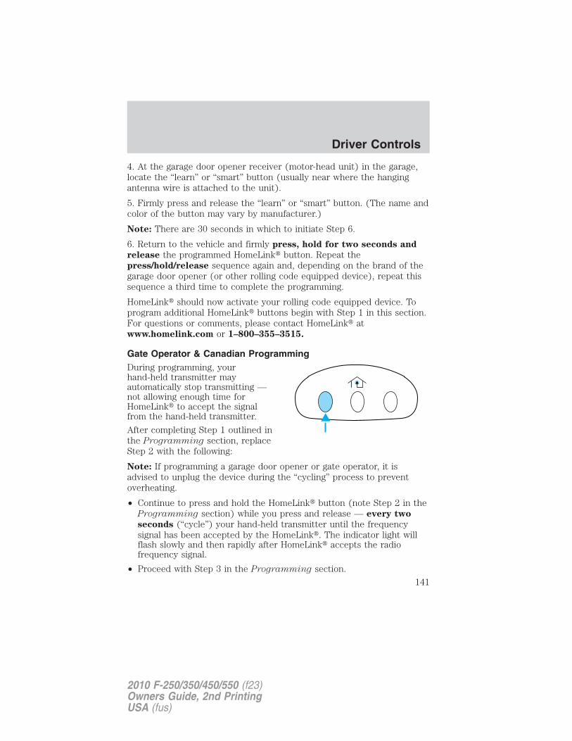
4. At the garage door opener receiver (motor-head unit) in the garage,locate the “learn” or “smart” button (usually near where the hangingantenna wire is attached to the unit).
5. Firmly press and release the “learn” or “smart” button. (The name andcolor of the button may vary by manufacturer.)
Note: There are 30 seconds in which to initiate Step 6.
6. Return to the vehicle and firmly press, hold for two seconds and
release the programmed HomeLink� button. Repeat thepress/hold/release sequence again and, depending on the brand of thegarage door opener (or other rolling code equipped device), repeat thissequence a third time to complete the programming.
HomeLink� should now activate your rolling code equipped device. Toprogram additional HomeLink� buttons begin with Step 1 in this section.For questions or comments, please contact HomeLink� atwww.homelink.com or 1–800–355–3515.
Gate Operator & Canadian ProgrammingDuring programming, yourhand-held transmitter mayautomatically stop transmitting —not allowing enough time forHomeLink� to accept the signalfrom the hand-held transmitter.
After completing Step 1 outlined inthe Programming section, replaceStep 2 with the following:
Note: If programming a garage door opener or gate operator, it isadvised to unplug the device during the “cycling” process to preventoverheating.
• Continue to press and hold the HomeLink� button (note Step 2 in theProgramming section) while you press and release — every two
seconds (“cycle”) your hand-held transmitter until the frequencysignal has been accepted by the HomeLink�. The indicator light willflash slowly and then rapidly after HomeLink� accepts the radiofrequency signal.
• Proceed with Step 3 in the Programming section.
Driver Controls
141
2010 F-250/350/450/550 (f23)Owners Guide, 2nd PrintingUSA (fus)
Operating the HomeLink� Wireless Control SystemTo operate, simply press and releasethe appropriate HomeLink� button.Activation will now occur for thetrained product (garage door, gateoperator, security system, entrydoor lock, or home or office lightingetc.). For convenience, thehand-held transmitter of the devicemay also be used at any time. In the event that there are stillprogramming difficulties, contact HomeLink� at www.homelink.com or1–800–355–3515.
Erasing HomeLink� buttonsTo erase the three programmedbuttons (individual buttons cannotbe erased):
• Press and hold the two outerHomeLink� buttons until theindicator light begins toflash-after 20 seconds. Releaseboth buttons. Do not hold forlonger that 30 seconds.
HomeLink� is now in the train (or learning) mode and can beprogrammed at any time beginning with Step 1 in the Programming
section.
Reprogramming a single HomeLink� button
To program a device to HomeLink� using a HomeLink� button previouslytrained, follow these steps:
1. Press and hold the desired HomeLink� button. Do NOT release thebutton.
2. The indicator light will begin to flash after 20 seconds. Withoutreleasing the HomeLink� button, follow Step 1 in the Programming
section.
For questions or comments, contact HomeLink� at www.homelink.comor 1–800–355–3515.
Driver Controls
142
2010 F-250/350/450/550 (f23)Owners Guide, 2nd PrintingUSA (fus)
TAILGATE LOCK (IF EQUIPPED)Your vehicle may be equipped with atailgate lock designed to helpprevent theft of the tailgate.
• Insert ignition key and turn to theright to engage lock.
• Turn ignition key to the left tounlock.
Tailgate removal
Your tailgate is removable to allow more room for loading.
WARNING: Always properly secure cargo to prevent shiftingcargo or cargo falling from vehicle, which could result in
compromised vehicle stability and serious personal injury to vehicleoccupants or others.
Note: If equipped with a rearview camera system, do Steps 1 through 3before removing the tailgate.
1. Before removal of the tailgate,locate and disconnect the tailgatein-line connector under the pickupbox on the passenger side of thevehicle near the spare tire.
2. Install a protective cap (locatedin the glove box) onto the in-linerearview camera system connectorthat remains under the pickup box.
3. Partially lower tailgate andcarefully feed tailgate harness up through the gap between the pickupbox and the bumper. Place the tailgate harness out of the way under thepickup box.
Driver Controls
143
2010 F-250/350/450/550 (f23)Owners Guide, 2nd PrintingUSA (fus)
4. Lower the tailgate.
5. Using a screwdriver, gently prythe spring clip (on each connector)past the head of the support screw.Disconnect cable.
6. Disconnect the other cable.
7. Lift tailgate to a 45-degree anglefrom horizontal.
8. Lift right side off of its hinge.9. Lift tailgate to a 80-degree angle from horizontal.10. Remove tailgate from left side hinge by sliding tailgate to the right.To install, follow the removal procedures in reverse order.
Tailgate step (if equipped)Your vehicle may be equipped with a feature that allows easier entry intothe truck bed. To open the tailgate step:
1. Flip down the tailgate.
2. Pull the yellow latch lever to theunlock positon ( ) to release thegrab handle from its stowed postionand raise the handle upright untilyou feel it latch and see the latchlever in the lock positon ( ). Theyellow lever only needs to be usedwhen releasing the grab handle.
3. Rotate the center molding tounlatch the tailgate step and pull ittowards you to extend it.
4. Flip open the step panel to widenthe step.
Note: To reduce risk of falling:
• Operate step only when thevehicle is on level surface.
• Operate step only in areas withsufficient lighting
• Always open flip panel to widen step.
Driver Controls
144
2010 F-250/350/450/550 (f23)Owners Guide, 2nd PrintingUSA (fus)
• Always use grab handle when stepping up and down.
• Step not intended for bare-footed use.
• Keep step clean from contamination before use (e.g. snow, mud)
• Keep the step load (you + load) below 350 lb (159 kg).
• Never drive with step deployed.
To close the tailgate step:
1. Close the step panel, then lift and fully close the tailgate step into thetailgate.
2. Slide the latch at the bottom of the handle, then lower the handle.
Note:
• Fully close and latch the tailgate step before moving the vehicle.
• Never drive with the step or grab handle deployed.
• Replace slip resistance tape (serviceable item) if worn out.
• Replace handle molding (serviceable item) if damaged.
• Do not tow with grab handle or step frame.
Bed extender (if equipped)
Your vehicle may be equipped with a cargo management feature in thetruck bed.
Note: This feature is not intended for off-road usage.
To open the bed extender into tailgate mode:
1. Pull the locking pin toward thecenter of the vehicle.
Driver Controls
145
2010 F-250/350/450/550 (f23)Owners Guide, 2nd PrintingUSA (fus)
2. Open the latches to release thepanels.
3. Rotate the panels toward thetailgate.
Repeat Steps 1–3 for the other side of the bed extender.
4. Connect the two panels, then rotate both knobs a quarter-turnclockwise to secure the panels.
Driver Controls
146
2010 F-250/350/450/550 (f23)Owners Guide, 2nd PrintingUSA (fus)
5. Ensure the latch rod is insertedinto the tailgate hole and the lockingpins on both sides are engaged intotheir holes in the pick-up box.
6. Reverse steps for storage of thebed extender.
Note: When the vehicle is in motion, ensure the locking pins and knobsare fully engaged.
Note: Ensure all cargo is secured.
Note: When the vehicle is in motion, the tailgate load must not exceed150 lb (68 kg).
Note: The bed extender should always be kept in the grocery mode orstowed position with the tailgate closed when not being used for thepurpose of restraining cargo in the tailgate mode.
To open the bed extender into grocery mode, follow Steps 1–4 byrotating the panels away from the tailgate. Close the tailgate.
Driver Controls
147
2010 F-250/350/450/550 (f23)Owners Guide, 2nd PrintingUSA (fus)
KEYS
The key operates all locks on your vehicle. You should always carry asecond key with you in a safe place in case you require it in anemergency.
If your vehicle is equipped with the SecuriLock� Passive Anti-theftsystem, your keys are electronically coded to your vehicle; using anon-coded key will not permit your vehicle to start. If you lose yourdealer supplied keys, replacement keys are available through yourauthorized dealer.
POWER DOOR LOCKS (IF EQUIPPED)Press control to unlock all doors.
Press control to lock all doors.
Smart locks (if equipped)This feature prevents you from locking yourself out of the vehicle if yourkey is still in the ignition.
When you open the driver’s door and you lock the vehicle with thepower door lock control, all the doors will lock, then the driver’s doorwill automatically unlock reminding you that your key is still in theignition.
The vehicle can still be locked, with the key in the ignition, using themanual lock button on the door, locking the driver’s door with a key, bysimultaneously pressing button 7 • 8 and the 9 • 0 controls on theremote entry keypad (if equipped), or using the button on theremote entry transmitter (if equipped).
Locks and Security
148
2010 F-250/350/450/550 (f23)Owners Guide, 2nd PrintingUSA (fus)
Autolock feature (if equipped)The autolock feature will lock all the doors when:• all the doors are closed,• the ignition is in the on position,
• you shift into any gear putting the vehicle in motion, and
• the vehicle attains a speed greater than 12 mph (20 km/h) for greaterthan two seconds.
The autolock feature repeats when:
• any door is opened then closed while the ignition is in the on positionand the vehicle speed is 9 mph (15 km/h) or lower, and
• the vehicle then attains a speed greater than 12 mph (20 km/h) forgreater than two seconds.
Deactivating/activating autolock featureThere are four methods to enable/disable this feature:
• Through your authorized dealer,
• by using a power door unlock/lock procedure,
• using a keypad procedure (if equipped), or
• or by using the instrument cluster message center (if equipped). Referto Message center in the Instrument Cluster chapter.
Note: The autolock feature can be activated/deactivated independentlyof the autounlock feature.
Power door lock switch autolock enable/disable procedureBefore starting, ensure the ignition is in the off position and all vehicledoors are closed. You must complete Steps 1–5 within 30 seconds or theprocedure will have to be repeated. If the procedure needs to berepeated, wait a minimum of 30 seconds before beginning again.
1. Place the key in the ignition andturn the ignition to the on position.
2. Press the power door unlockcontrol on the door panel threetimes.
3. Turn the ignition from the onposition to the off position.
4. Press the power door unlock control on the door panel three times.
Locks and Security
149
2010 F-250/350/450/550 (f23)Owners Guide, 2nd PrintingUSA (fus)
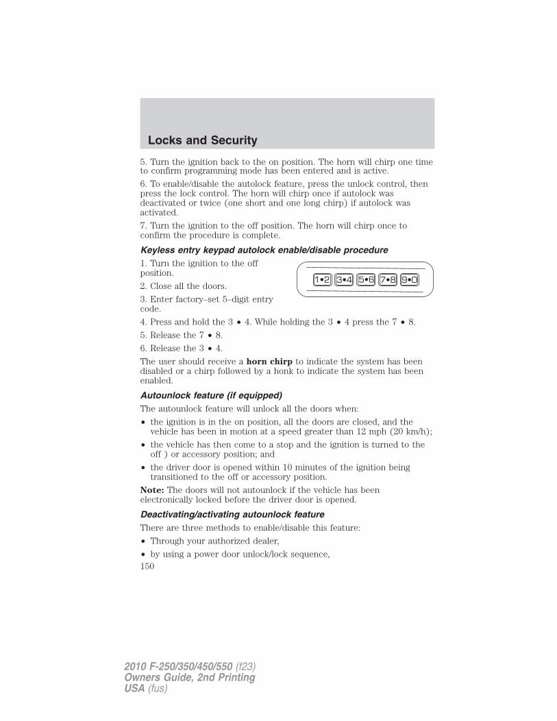
5. Turn the ignition back to the on position. The horn will chirp one timeto confirm programming mode has been entered and is active.
6. To enable/disable the autolock feature, press the unlock control, thenpress the lock control. The horn will chirp once if autolock wasdeactivated or twice (one short and one long chirp) if autolock wasactivated.
7. Turn the ignition to the off position. The horn will chirp once toconfirm the procedure is complete.
Keyless entry keypad autolock enable/disable procedure1. Turn the ignition to the offposition.
2. Close all the doors.
3. Enter factory–set 5–digit entrycode.
4. Press and hold the 3 • 4. While holding the 3 • 4 press the 7 • 8.
5. Release the 7 • 8.
6. Release the 3 • 4.
The user should receive a horn chirp to indicate the system has beendisabled or a chirp followed by a honk to indicate the system has beenenabled.
Autounlock feature (if equipped)The autounlock feature will unlock all the doors when:
• the ignition is in the on position, all the doors are closed, and thevehicle has been in motion at a speed greater than 12 mph (20 km/h);
• the vehicle has then come to a stop and the ignition is turned to theoff ) or accessory position; and
• the driver door is opened within 10 minutes of the ignition beingtransitioned to the off or accessory position.
Note: The doors will not autounlock if the vehicle has beenelectronically locked before the driver door is opened.
Deactivating/activating autounlock featureThere are three methods to enable/disable this feature:
• Through your authorized dealer,
• by using a power door unlock/lock sequence,
Locks and Security
150
2010 F-250/350/450/550 (f23)Owners Guide, 2nd PrintingUSA (fus)
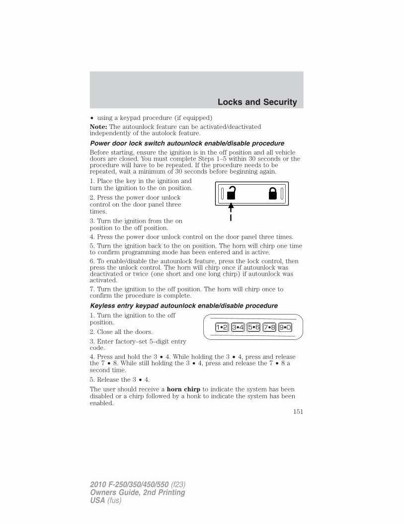
• using a keypad procedure (if equipped)Note: The autounlock feature can be activated/deactivatedindependently of the autolock feature.
Power door lock switch autounlock enable/disable procedureBefore starting, ensure the ignition is in the off position and all vehicledoors are closed. You must complete Steps 1–5 within 30 seconds or theprocedure will have to be repeated. If the procedure needs to berepeated, wait a minimum of 30 seconds before beginning again.
1. Place the key in the ignition andturn the ignition to the on position.
2. Press the power door unlockcontrol on the door panel threetimes.
3. Turn the ignition from the onposition to the off position.4. Press the power door unlock control on the door panel three times.5. Turn the ignition back to the on position. The horn will chirp one timeto confirm programming mode has been entered and is active.6. To enable/disable the autounlock feature, press the lock control, thenpress the unlock control. The horn will chirp once if autounlock wasdeactivated or twice (one short and one long chirp) if autounlock wasactivated.7. Turn the ignition to the off position. The horn will chirp once toconfirm the procedure is complete.
Keyless entry keypad autounlock enable/disable procedure1. Turn the ignition to the offposition.
2. Close all the doors.
3. Enter factory–set 5–digit entrycode.4. Press and hold the 3 • 4. While holding the 3 • 4, press and releasethe 7 • 8. While still holding the 3 • 4, press and release the 7 • 8 asecond time.
5. Release the 3 • 4.
The user should receive a horn chirp to indicate the system has beendisabled or a chirp followed by a honk to indicate the system has beenenabled.
Locks and Security
151
2010 F-250/350/450/550 (f23)Owners Guide, 2nd PrintingUSA (fus)
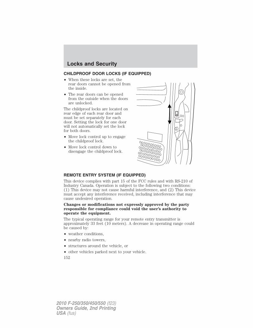
CHILDPROOF DOOR LOCKS (IF EQUIPPED)• When these locks are set, the
rear doors cannot be opened fromthe inside.
• The rear doors can be openedfrom the outside when the doorsare unlocked.
The childproof locks are located onrear edge of each rear door andmust be set separately for eachdoor. Setting the lock for one doorwill not automatically set the lockfor both doors.
• Move lock control up to engagethe childproof lock.
• Move lock control down todisengage the childproof lock.
REMOTE ENTRY SYSTEM (IF EQUIPPED)This device complies with part 15 of the FCC rules and with RS-210 ofIndustry Canada. Operation is subject to the following two conditions:(1) This device may not cause harmful interference, and (2) This devicemust accept any interference received, including interference that maycause undesired operation.
Changes or modifications not expressly approved by the partyresponsible for compliance could void the user’s authority tooperate the equipment.
The typical operating range for your remote entry transmitter isapproximately 33 feet (10 meters). A decrease in operating range couldbe caused by:
• weather conditions,
• nearby radio towers,
• structures around the vehicle, or
• other vehicles parked next to your vehicle.
Locks and Security
152
2010 F-250/350/450/550 (f23)Owners Guide, 2nd PrintingUSA (fus)
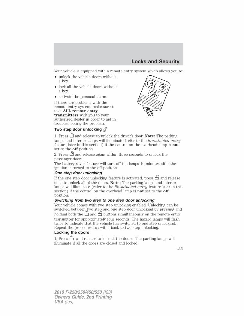
Your vehicle is equipped with a remote entry system which allows you to:
• unlock the vehicle doors withouta key.
• lock all the vehicle doors withouta key.
• activate the personal alarm.
If there are problems with theremote entry system, make sure totake ALL remote entrytransmitters with you to yourauthorized dealer in order to aid introubleshooting the problem.
Two step door unlocking
1. Press and release to unlock the driver’s door. Note: The parkinglamps and interior lamps will illuminate (refer to the Illuminated entryfeature later in this section) if the control on the overhead lamp is notset to the off position.2. Press and release again within three seconds to unlock thepassenger doors.The battery saver feature will turn off the lamps 10 minutes after theignition is turned to the off position.One step door unlockingIf the one step door unlocking feature is activated, press and releaseonce to unlock all of the doors. Note: The parking lamps and interiorlamps will illuminate (refer to the Illuminated entry feature later in thissection) if the control on the overhead lamp is not set to the offposition.Switching from two step to one step door unlockingYour vehicle comes with two step unlocking enabled. Unlocking can beswitched between two step and one step door unlocking by pressing andholding both the and buttons simultaneously on the remote entrytransmitter for approximately four seconds. The hazard lamps will flashtwice to indicate that the vehicle has switched to one step unlocking.Repeat the procedure to switch back to two-step unlocking.Locking the doors
1. Press and release to lock all the doors. The parking lamps willilluminate if all the doors are closed and locked.
Locks and Security
153
2010 F-250/350/450/550 (f23)Owners Guide, 2nd PrintingUSA (fus)
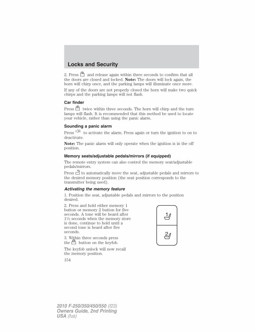
2. Press and release again within three seconds to confirm that allthe doors are closed and locked. Note: The doors will lock again, thehorn will chirp once, and the parking lamps will illuminate once more.
If any of the doors are not properly closed the horn will make two quickchirps and the parking lamps will not flash.
Car finder
Press twice within three seconds. The horn will chirp and the turnlamps will flash. It is recommended that this method be used to locateyour vehicle, rather than using the panic alarm.
Sounding a panic alarm
Press to activate the alarm. Press again or turn the ignition to on todeactivate.
Note: The panic alarm will only operate when the ignition is in the offposition.
Memory seats/adjustable pedals/mirrors (if equipped)The remote entry system can also control the memory seat/adjustablepedals/mirrors.
Press to automatically move the seat, adjustable pedals and mirrors tothe desired memory position (the seat position corresponds to thetransmitter being used).
Activating the memory feature1. Position the seat, adjustable pedals and mirrors to the positiondesired.
2. Press and hold either memory 1button or memory 2 button for fiveseconds. A tone will be heard after11⁄2 seconds when the memory storeis done, continue to hold until asecond tone is heard after fiveseconds.
3. Within three seconds pressthe button on the keyfob.
The keyfob unlock will now recallthe memory position.
Locks and Security
154
2010 F-250/350/450/550 (f23)Owners Guide, 2nd PrintingUSA (fus)
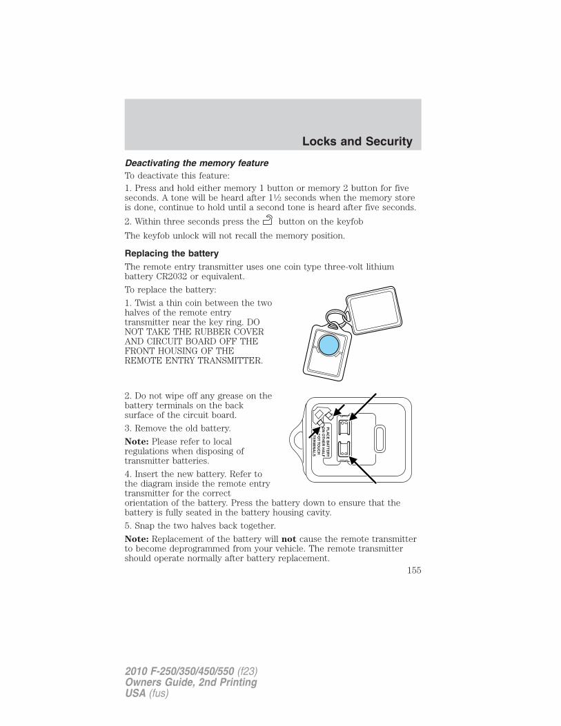
Deactivating the memory featureTo deactivate this feature:1. Press and hold either memory 1 button or memory 2 button for fiveseconds. A tone will be heard after 11⁄2 seconds when the memory storeis done, continue to hold until a second tone is heard after five seconds.
2. Within three seconds press the button on the keyfob
The keyfob unlock will not recall the memory position.
Replacing the batteryThe remote entry transmitter uses one coin type three-volt lithiumbattery CR2032 or equivalent.
To replace the battery:
1. Twist a thin coin between the twohalves of the remote entrytransmitter near the key ring. DONOT TAKE THE RUBBER COVERAND CIRCUIT BOARD OFF THEFRONT HOUSING OF THEREMOTE ENTRY TRANSMITTER.
2. Do not wipe off any grease on thebattery terminals on the backsurface of the circuit board.
3. Remove the old battery.
Note: Please refer to localregulations when disposing oftransmitter batteries.
4. Insert the new battery. Refer tothe diagram inside the remote entrytransmitter for the correctorientation of the battery. Press the battery down to ensure that thebattery is fully seated in the battery housing cavity.
5. Snap the two halves back together.
Note: Replacement of the battery will not cause the remote transmitterto become deprogrammed from your vehicle. The remote transmittershould operate normally after battery replacement.
Locks and Security
155
2010 F-250/350/450/550 (f23)Owners Guide, 2nd PrintingUSA (fus)
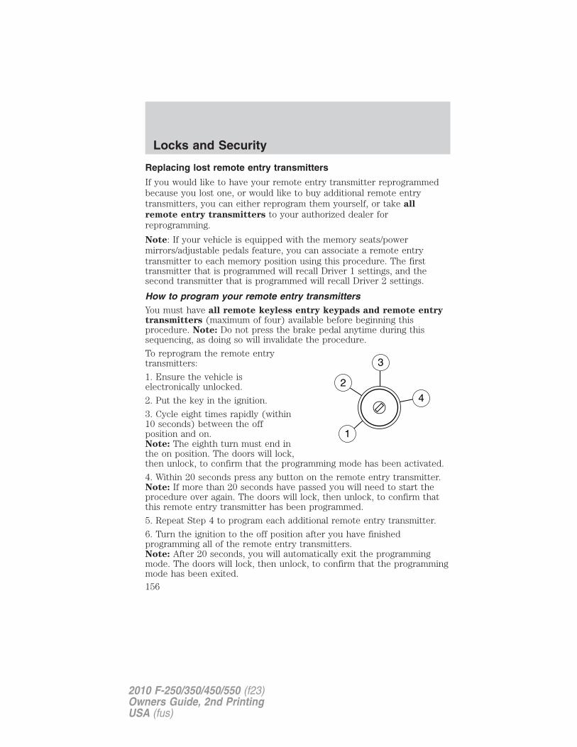
Replacing lost remote entry transmitters
If you would like to have your remote entry transmitter reprogrammedbecause you lost one, or would like to buy additional remote entrytransmitters, you can either reprogram them yourself, or take all
remote entry transmitters to your authorized dealer forreprogramming.
Note: If your vehicle is equipped with the memory seats/powermirrors/adjustable pedals feature, you can associate a remote entrytransmitter to each memory position using this procedure. The firsttransmitter that is programmed will recall Driver 1 settings, and thesecond transmitter that is programmed will recall Driver 2 settings.
How to program your remote entry transmittersYou must have all remote keyless entry keypads and remote entrytransmitters (maximum of four) available before beginning thisprocedure. Note: Do not press the brake pedal anytime during thissequencing, as doing so will invalidate the procedure.
To reprogram the remote entrytransmitters:
1. Ensure the vehicle iselectronically unlocked.
2. Put the key in the ignition.
3. Cycle eight times rapidly (within10 seconds) between the offposition and on.Note: The eighth turn must end inthe on position. The doors will lock,then unlock, to confirm that the programming mode has been activated.
4. Within 20 seconds press any button on the remote entry transmitter.Note: If more than 20 seconds have passed you will need to start theprocedure over again. The doors will lock, then unlock, to confirm thatthis remote entry transmitter has been programmed.
5. Repeat Step 4 to program each additional remote entry transmitter.
6. Turn the ignition to the off position after you have finishedprogramming all of the remote entry transmitters.Note: After 20 seconds, you will automatically exit the programmingmode. The doors will lock, then unlock, to confirm that the programmingmode has been exited.
Locks and Security
156
2010 F-250/350/450/550 (f23)Owners Guide, 2nd PrintingUSA (fus)
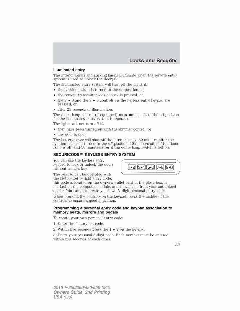
Illuminated entryThe interior lamps and parking lamps illuminate when the remote entrysystem is used to unlock the door(s).The illuminated entry system will turn off the lights if:• the ignition switch is turned to the on position, or• the remote transmitter lock control is pressed, or• the 7 • 8 and the 9 • 0 controls on the keyless entry keypad are
pressed, or• after 25 seconds of illumination.The dome lamp control (if equipped) must not be set to the off positionfor the illuminated entry system to operate.The lights will not turn off if:• they have been turned on with the dimmer control, or• any door is open.The battery saver will shut off the interior lamps 30 minutes after theignition has been turned to the off position, 10 minutes after if the domelamp is off, and 30 minutes after if the dome lamp switch is left on.
SECURICODE™ KEYLESS ENTRY SYSTEMYou can use the keyless entrykeypad to lock or unlock the doorswithout using a key.
The keypad can be operated withthe factory set 5–digit entry code;this code is located on the owner’s wallet card in the glove box, ismarked on the computer module, and is available from your authorizeddealer. You can also create your own 5–digit personal entry code.
When pressing the controls on the keypad, press the middle of thecontrols to ensure a good activation.
Programming a personal entry code and keypad association tomemory seats, mirrors and pedalsTo create your own personal entry code:
1. Enter the factory set code.
2. Within five seconds press the 1 • 2 on the keypad.
3. Enter your personal 5-digit code. Each number must be enteredwithin five seconds of each other.
Locks and Security
157
2010 F-250/350/450/550 (f23)Owners Guide, 2nd PrintingUSA (fus)
4. To associate the entry code with a memory setting, enter a sixth digitto indicate which driver should be set in a memory recalled by thepersonal entry code:
• Pressing 1 • 2 recalls Driver 1 settings.
• Pressing 3 • 4 recalls Driver 2 settings.
• Pressing other keypad buttons or not pressing a keypad button as asixth digit does not set a driver and will not recall a memory setting.Note: The factory-set code cannot be associated with a memorysetting.
5. The doors will again lock then unlock to confirm that your personalkeycode has been programmed to the module.
Tips:
• Do not set a code that uses five of the same number.
• Do not use five numbers in sequential order.
• The factory set code will work even if you have set your own personalcode.
Erasing personal code1. Enter the factory set 5–digit code.
2. Within five seconds, press the 1 • 2 on the keypad and release.
3. Press and hold the 1 • 2 for two seconds. This must be done withinfive seconds of completing Step 2.
Your personal code is now erased and only the factory set 5–digit codewill work.
Anti-scan featureIf an incorrect code has been entered seven times (35 consecutivebutton presses), the keypad will go into an anti-scan mode. This modedisables the keypad for one minute and the keypad lamp will flash duringthis time.
The anti-scan feature will turn off after:
• one minute of keypad inactivity.
• pressing the control on the remote entry transmitter.
• the ignition is turned to the on position.
Locks and Security
158
2010 F-250/350/450/550 (f23)Owners Guide, 2nd PrintingUSA (fus)
Unlocking and locking the doors using keyless entry
To unlock the driver’s door, enter the factory set 5-digit code or yourpersonal code. Each number must be pressed within five seconds of eachother. The interior lamps will illuminate after entering a valid keypadentry code.
To unlock all doors, press the 3 • 4 control within five seconds.
To lock all doors, press the 7 • 8 and the 9 • 0 at the same time. Youdo not need to enter the keypad code first. Note: The interior lampswill turn off.
SECURILOCK� PASSIVE ANTI-THEFT SYSTEM (IF EQUIPPED)
SecuriLock� passive anti-theft system is an engine immobilizationsystem. This system is designed to help prevent the engine from beingstarted unless a coded key programmed to your vehicle is used. Theuse of the wrong type of coded key may lead to a “no-start” condition.
Your vehicle comes with two coded keys; additional coded keys may bepurchased from your authorized dealer. The authorized dealer canprogram your spare keys to your vehicle or you can program the keysyourself. Refer to Programming spare keys for instructions on how toprogram the coded key.
Note: The SecuriLock� passive anti-theft system is not compatible withnon-Ford aftermarket remote start systems. Use of these systems mayresult in vehicle starting problems and a loss of security protection.
Note: Large metallic objects, electronic devices that are used topurchase gasoline or similar items, or a second coded key on the samekey chain may cause vehicle starting issues. You need to prevent theseobjects from touching the coded key while starting the engine. Theseobjects will not cause damage to the coded key, but may cause amomentary issue if they are too close to the key when starting theengine. If a problem occurs, turn the ignition off, remove all objects onthe key chain away from the coded key and restart the engine.
Note: Do not leave a duplicate coded key in the vehicle. Alwaystake your keys and lock all doors when leaving the vehicle.
Locks and Security
159
2010 F-250/350/450/550 (f23)Owners Guide, 2nd PrintingUSA (fus)
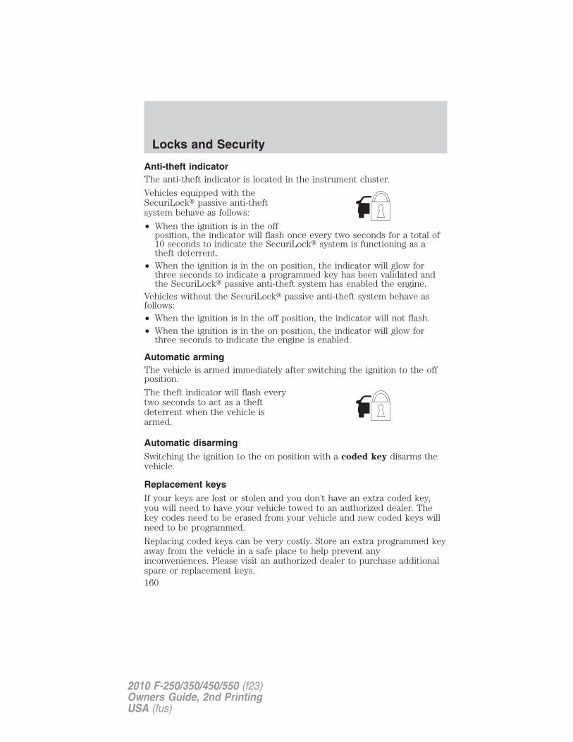
Anti-theft indicatorThe anti-theft indicator is located in the instrument cluster.
Vehicles equipped with theSecuriLock� passive anti-theftsystem behave as follows:
• When the ignition is in the offposition, the indicator will flash once every two seconds for a total of10 seconds to indicate the SecuriLock� system is functioning as atheft deterrent.
• When the ignition is in the on position, the indicator will glow forthree seconds to indicate a programmed key has been validated andthe SecuriLock� passive anti-theft system has enabled the engine.
Vehicles without the SecuriLock� passive anti-theft system behave asfollows:• When the ignition is in the off position, the indicator will not flash.• When the ignition is in the on position, the indicator will glow for
three seconds to indicate the engine is enabled.
Automatic armingThe vehicle is armed immediately after switching the ignition to the offposition.
The theft indicator will flash everytwo seconds to act as a theftdeterrent when the vehicle isarmed.
Automatic disarmingSwitching the ignition to the on position with a coded key disarms thevehicle.
Replacement keysIf your keys are lost or stolen and you don’t have an extra coded key,you will need to have your vehicle towed to an authorized dealer. Thekey codes need to be erased from your vehicle and new coded keys willneed to be programmed.
Replacing coded keys can be very costly. Store an extra programmed keyaway from the vehicle in a safe place to help prevent anyinconveniences. Please visit an authorized dealer to purchase additionalspare or replacement keys.
Locks and Security
160
2010 F-250/350/450/550 (f23)Owners Guide, 2nd PrintingUSA (fus)
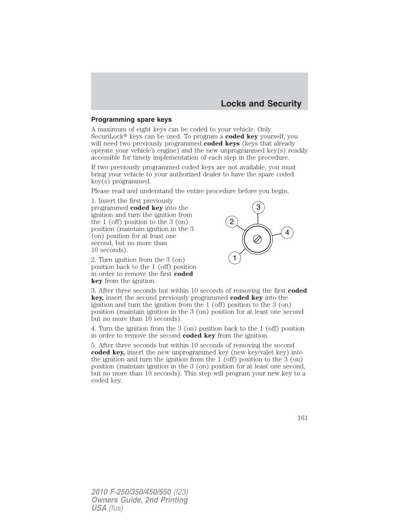
Programming spare keysA maximum of eight keys can be coded to your vehicle. OnlySecuriLock� keys can be used. To program a coded key yourself, youwill need two previously programmed coded keys (keys that alreadyoperate your vehicle’s engine) and the new unprogrammed key(s) readilyaccessible for timely implementation of each step in the procedure.
If two previously programmed coded keys are not available, you mustbring your vehicle to your authorized dealer to have the spare codedkey(s) programmed.
Please read and understand the entire procedure before you begin.
1. Insert the first previouslyprogrammed coded key into theignition and turn the ignition fromthe 1 (off) position to the 3 (on)position (maintain ignition in the 3(on) position for at least onesecond, but no more than10 seconds).
2. Turn ignition from the 3 (on)position back to the 1 (off) positionin order to remove the first codedkey from the ignition.
3. After three seconds but within 10 seconds of removing the first codedkey, insert the second previously programmed coded key into theignition and turn the ignition from the 1 (off) position to the 3 (on)position (maintain ignition in the 3 (on) position for at least one secondbut no more than 10 seconds).
4. Turn the ignition from the 3 (on) position back to the 1 (off) positionin order to remove the second coded key from the ignition.
5. After three seconds but within 10 seconds of removing the secondcoded key, insert the new unprogrammed key (new key/valet key) intothe ignition and turn the ignition from the 1 (off) position to the 3 (on)position (maintain ignition in the 3 (on) position for at least one second,but no more than 10 seconds). This step will program your new key to acoded key.
Locks and Security
161
2010 F-250/350/450/550 (f23)Owners Guide, 2nd PrintingUSA (fus)
6. To program additional new unprogrammed key(s), repeat Steps 1through 5.
If successful, the new coded key(s) will start the vehicle’s engine and thetheft indicator will illuminate for three seconds and then go out.
If not successful, the new coded key(s) will not start the vehicle’s engineand the theft indicator will flash on and off and you may repeat Steps 1through 5. If failure repeats, bring your vehicle to your authorized dealerto have the new spare key(s) programmed.
PERIMETER ALARM SYSTEM (IF EQUIPPED)The perimeter anti-theft system will warn you in the event of anunauthorized entry to your vehicle.
If there is any potential perimeter anti-theft problem with your vehicle,ensure ALL remote entry transmitters are taken to the authorizeddealer to aid in troubleshooting.
Arming the systemWhen armed, this system will respond if unauthorized entry isattempted. When unauthorized entry occurs, the system will flash thepark/turn lamps and will sound the horn.
The system is ready to arm whenever the key is removed from theignition. Either of the following actions will prearm the alarm system:
• Press the control on the remote entry transmitter.
• Open a door and press the power door lock control to lock all thedoors, and then close the door.
• Press and hold the 7 • 8 and 9 • 0 controls on the keyless entry padat the same time to lock the doors (driver’s door must be closed).
There is a 20 second countdown when any of the above actions occurbefore the vehicle becomes armed.
Each door and the hood is armed individually, and if any are open, theymust be closed before the open entry point can enter the 20 secondcountdown.
The turn signal lamps will flash once when all doors and the hood areclosed indicating the vehicle is locked and entering the 20 secondcountdown.
Locks and Security
162
2010 F-250/350/450/550 (f23)Owners Guide, 2nd PrintingUSA (fus)
Disarming the systemYou can disarm the system by any of the following actions:
• Unlock the doors by pressing the control on your remote entrytransmitter.
• Turn the ignition to the on position with a programmed coded ignitionkey.
Triggering the anti-theft systemThe armed system will be triggered if any door or hood is openedwithout using the key or the remote entry transmitter.
Locks and Security
163
2010 F-250/350/450/550 (f23)Owners Guide, 2nd PrintingUSA (fus)
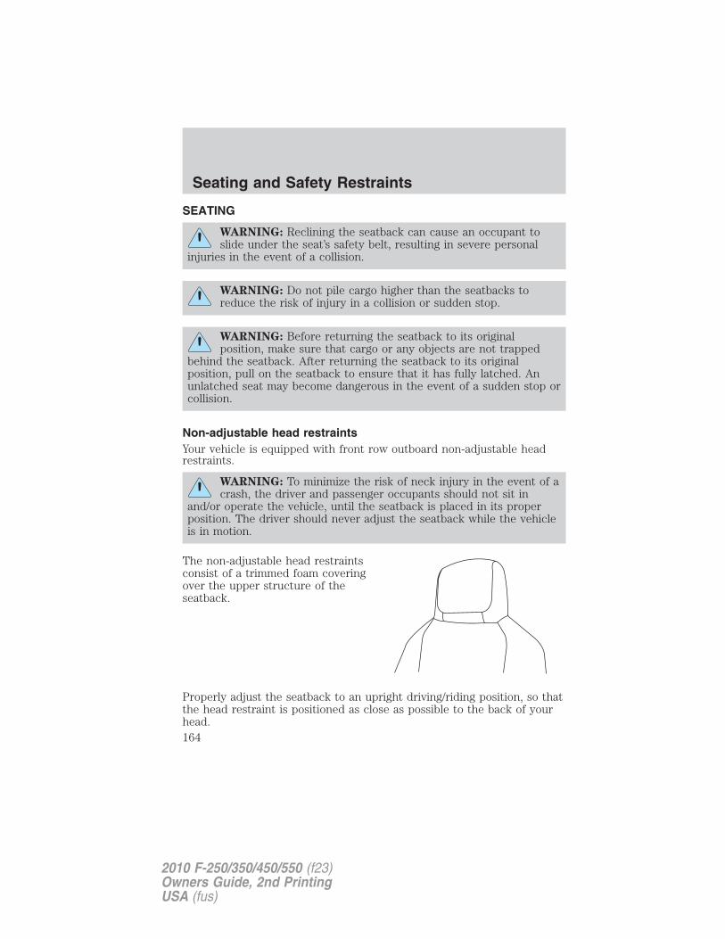
SEATING
WARNING: Reclining the seatback can cause an occupant toslide under the seat’s safety belt, resulting in severe personal
injuries in the event of a collision.
WARNING: Do not pile cargo higher than the seatbacks toreduce the risk of injury in a collision or sudden stop.
WARNING: Before returning the seatback to its originalposition, make sure that cargo or any objects are not trapped
behind the seatback. After returning the seatback to its originalposition, pull on the seatback to ensure that it has fully latched. Anunlatched seat may become dangerous in the event of a sudden stop orcollision.
Non-adjustable head restraintsYour vehicle is equipped with front row outboard non-adjustable headrestraints.
WARNING: To minimize the risk of neck injury in the event of acrash, the driver and passenger occupants should not sit in
and/or operate the vehicle, until the seatback is placed in its properposition. The driver should never adjust the seatback while the vehicleis in motion.
The non-adjustable head restraintsconsist of a trimmed foam coveringover the upper structure of theseatback.
Properly adjust the seatback to an upright driving/riding position, so thatthe head restraint is positioned as close as possible to the back of yourhead.
Seating and Safety Restraints
164
2010 F-250/350/450/550 (f23)Owners Guide, 2nd PrintingUSA (fus)
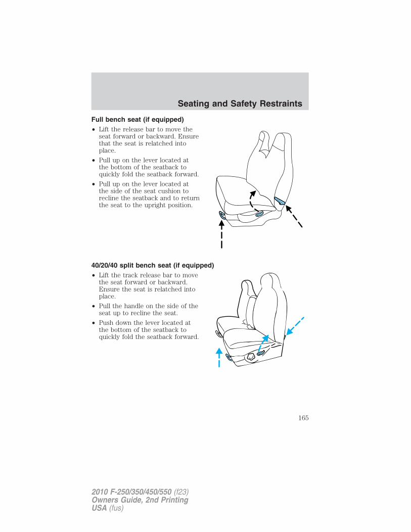
Full bench seat (if equipped)• Lift the release bar to move the
seat forward or backward. Ensurethat the seat is relatched intoplace.
• Pull up on the lever located atthe bottom of the seatback toquickly fold the seatback forward.
• Pull up on the lever located atthe side of the seat cushion torecline the seatback and to returnthe seat to the upright position.
40/20/40 split bench seat (if equipped)• Lift the track release bar to move
the seat forward or backward.Ensure the seat is relatched intoplace.
• Pull the handle on the side of theseat up to recline the seat.
• Push down the lever located atthe bottom of the seatback toquickly fold the seatback forward.
Seating and Safety Restraints
165
2010 F-250/350/450/550 (f23)Owners Guide, 2nd PrintingUSA (fus)
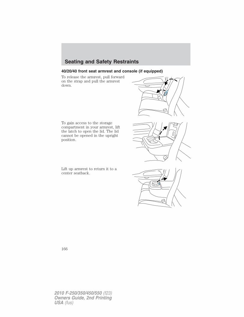
40/20/40 front seat armrest and console (if equipped)To release the armrest, pull forwardon the strap and pull the armrestdown.
To gain access to the storagecompartment in your armrest, liftthe latch to open the lid. The lidcannot be opened in the uprightposition.
Lift up armrest to return it to acenter seatback.
Seating and Safety Restraints
166
2010 F-250/350/450/550 (f23)Owners Guide, 2nd PrintingUSA (fus)
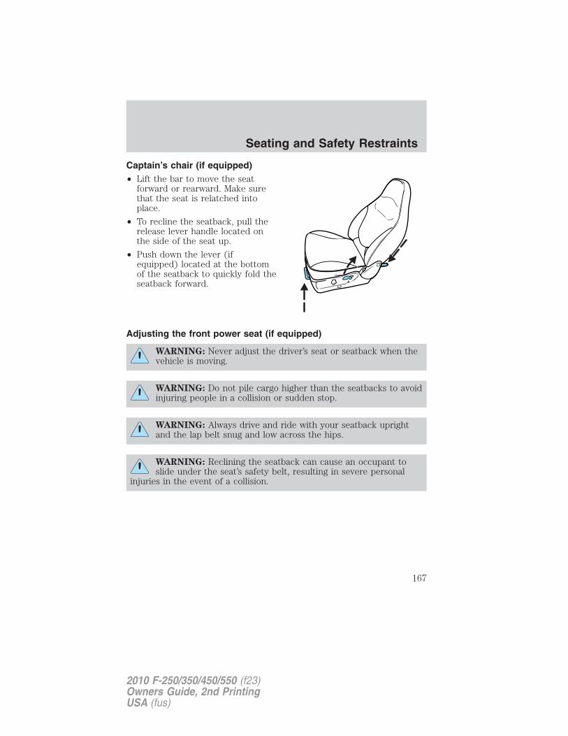
Captain’s chair (if equipped)• Lift the bar to move the seat
forward or rearward. Make surethat the seat is relatched intoplace.
• To recline the seatback, pull therelease lever handle located onthe side of the seat up.
• Push down the lever (ifequipped) located at the bottomof the seatback to quickly fold theseatback forward.
Adjusting the front power seat (if equipped)
WARNING: Never adjust the driver’s seat or seatback when thevehicle is moving.
WARNING: Do not pile cargo higher than the seatbacks to avoidinjuring people in a collision or sudden stop.
WARNING: Always drive and ride with your seatback uprightand the lap belt snug and low across the hips.
WARNING: Reclining the seatback can cause an occupant toslide under the seat’s safety belt, resulting in severe personal
injuries in the event of a collision.
Seating and Safety Restraints
167
2010 F-250/350/450/550 (f23)Owners Guide, 2nd PrintingUSA (fus)
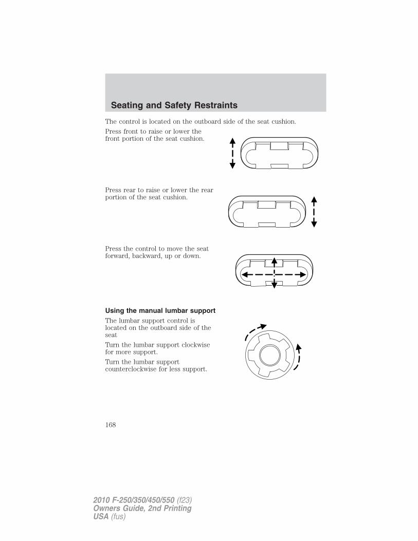
The control is located on the outboard side of the seat cushion.
Press front to raise or lower thefront portion of the seat cushion.
Press rear to raise or lower the rearportion of the seat cushion.
Press the control to move the seatforward, backward, up or down.
Using the manual lumbar supportThe lumbar support control islocated on the outboard side of theseat
Turn the lumbar support clockwisefor more support.
Turn the lumbar supportcounterclockwise for less support.
Seating and Safety Restraints
168
2010 F-250/350/450/550 (f23)Owners Guide, 2nd PrintingUSA (fus)
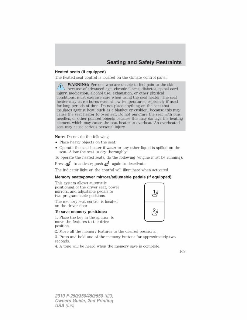
Heated seats (if equipped)The heated seat control is located on the climate control panel.
WARNING: Persons who are unable to feel pain to the skinbecause of advanced age, chronic illness, diabetes, spinal cord
injury, medication, alcohol use, exhaustion, or other physicalconditions, must exercise care when using the seat heater. The seatheater may cause burns even at low temperatures, especially if usedfor long periods of time. Do not place anything on the seat thatinsulates against heat, such as a blanket or cushion, because this maycause the seat heater to overheat. Do not puncture the seat with pins,needles, or other pointed objects because this may damage the heatingelement which may cause the seat heater to overheat. An overheatedseat may cause serious personal injury.
Note: Do not do the following:• Place heavy objects on the seat.• Operate the seat heater if water or any other liquid is spilled on the
seat. Allow the seat to dry thoroughly.To operate the heated seats, do the following (engine must be running):
Press to activate; push again to deactivate.
The indicator light on the control will illuminate when activated.
Memory seats/power mirrors/adjustable pedals (if equipped)This system allows automaticpositioning of the driver seat, powermirrors, and adjustable pedals totwo programmable positions.
The memory seat control is locatedon the driver door.
To save memory positions:
1. Place the key in the ignition tomove the features to the driveposition.2. Move all the memory features to the desired positions.3. Press and hold one of the memory buttons for approximately twoseconds.4. A tone will be heard when the memory save is complete.
Seating and Safety Restraints
169
2010 F-250/350/450/550 (f23)Owners Guide, 2nd PrintingUSA (fus)
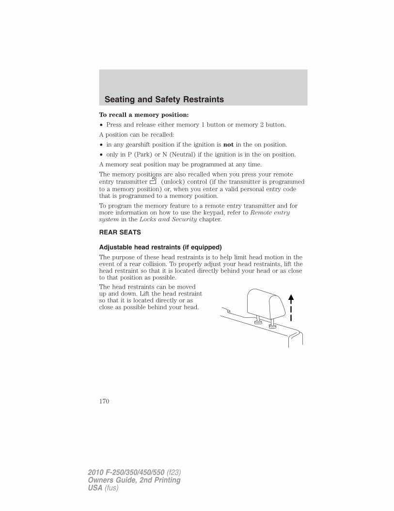
To recall a memory position:
• Press and release either memory 1 button or memory 2 button.
A position can be recalled:
• in any gearshift position if the ignition is not in the on position.
• only in P (Park) or N (Neutral) if the ignition is in the on position.
A memory seat position may be programmed at any time.
The memory positions are also recalled when you press your remoteentry transmitter (unlock) control (if the transmitter is programmedto a memory position) or, when you enter a valid personal entry codethat is programmed to a memory position.
To program the memory feature to a remote entry transmitter and formore information on how to use the keypad, refer to Remote entrysystem in the Locks and Security chapter.
REAR SEATS
Adjustable head restraints (if equipped)
The purpose of these head restraints is to help limit head motion in theevent of a rear collision. To properly adjust your head restraints, lift thehead restraint so that it is located directly behind your head or as closeto that position as possible.
The head restraints can be movedup and down. Lift the head restraintso that it is located directly or asclose as possible behind your head.
Seating and Safety Restraints
170
2010 F-250/350/450/550 (f23)Owners Guide, 2nd PrintingUSA (fus)
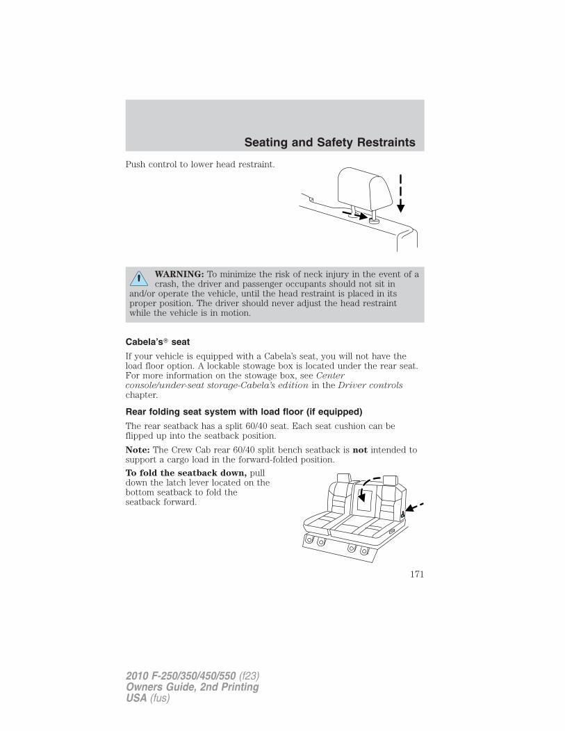
Push control to lower head restraint.
WARNING: To minimize the risk of neck injury in the event of acrash, the driver and passenger occupants should not sit in
and/or operate the vehicle, until the head restraint is placed in itsproper position. The driver should never adjust the head restraintwhile the vehicle is in motion.
Cabela’s� seat
If your vehicle is equipped with a Cabela’s seat, you will not have theload floor option. A lockable stowage box is located under the rear seat.For more information on the stowage box, see Centerconsole/under-seat storage-Cabela’s edition in the Driver controlschapter.
Rear folding seat system with load floor (if equipped)
The rear seatback has a split 60/40 seat. Each seat cushion can beflipped up into the seatback position.
Note: The Crew Cab rear 60/40 split bench seatback is not intended tosupport a cargo load in the forward-folded position.
To fold the seatback down, pulldown the latch lever located on thebottom seatback to fold theseatback forward.
Seating and Safety Restraints
171
2010 F-250/350/450/550 (f23)Owners Guide, 2nd PrintingUSA (fus)
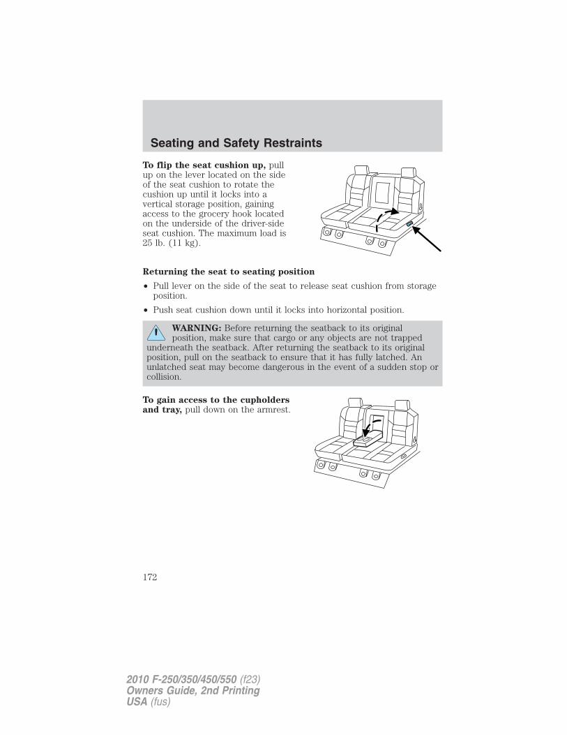
To flip the seat cushion up, pullup on the lever located on the sideof the seat cushion to rotate thecushion up until it locks into avertical storage position, gainingaccess to the grocery hook locatedon the underside of the driver-sideseat cushion. The maximum load is25 lb. (11 kg).
Returning the seat to seating position
• Pull lever on the side of the seat to release seat cushion from storageposition.
• Push seat cushion down until it locks into horizontal position.
WARNING: Before returning the seatback to its originalposition, make sure that cargo or any objects are not trapped
underneath the seatback. After returning the seatback to its originalposition, pull on the seatback to ensure that it has fully latched. Anunlatched seat may become dangerous in the event of a sudden stop orcollision.
To gain access to the cupholdersand tray, pull down on the armrest.
Seating and Safety Restraints
172
2010 F-250/350/450/550 (f23)Owners Guide, 2nd PrintingUSA (fus)
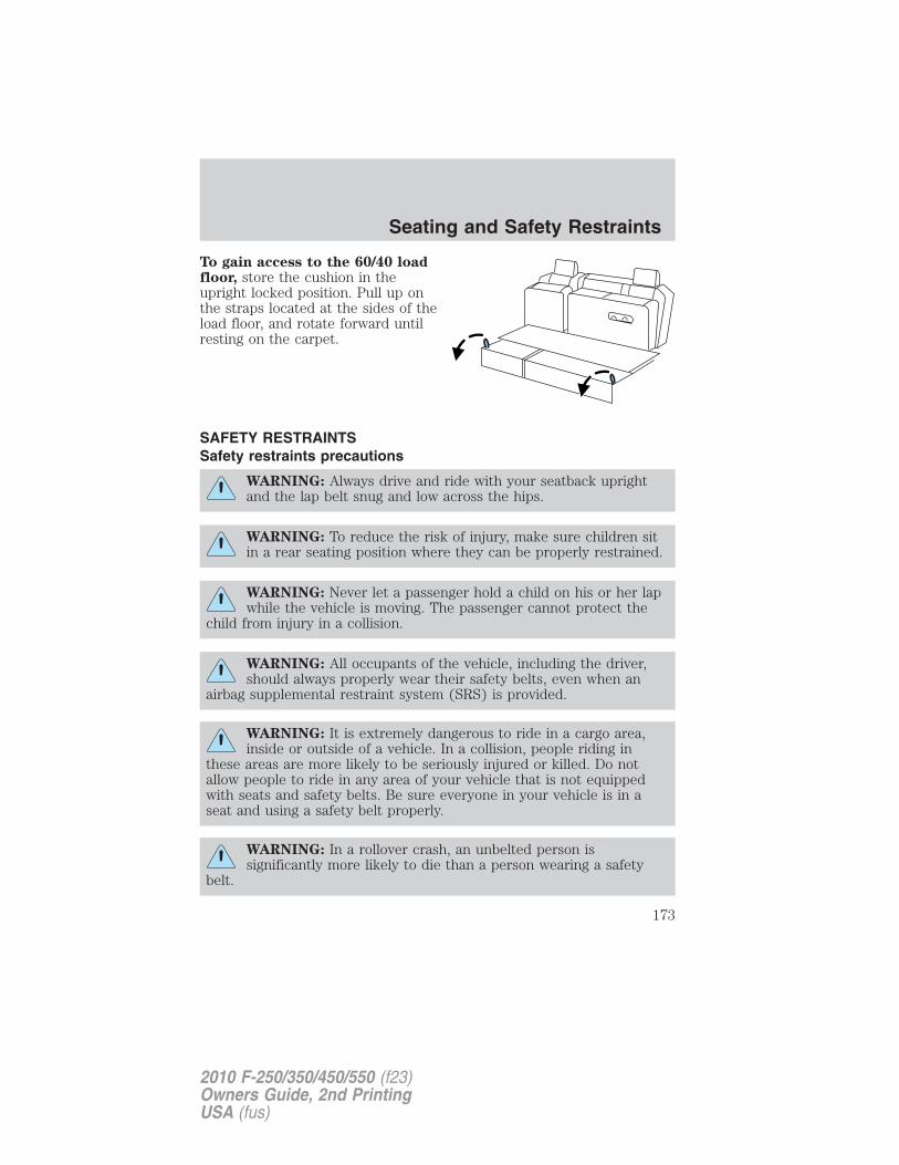
To gain access to the 60/40 loadfloor, store the cushion in theupright locked position. Pull up onthe straps located at the sides of theload floor, and rotate forward untilresting on the carpet.
SAFETY RESTRAINTSSafety restraints precautions
WARNING: Always drive and ride with your seatback uprightand the lap belt snug and low across the hips.
WARNING: To reduce the risk of injury, make sure children sitin a rear seating position where they can be properly restrained.
WARNING: Never let a passenger hold a child on his or her lapwhile the vehicle is moving. The passenger cannot protect the
child from injury in a collision.
WARNING: All occupants of the vehicle, including the driver,should always properly wear their safety belts, even when an
airbag supplemental restraint system (SRS) is provided.
WARNING: It is extremely dangerous to ride in a cargo area,inside or outside of a vehicle. In a collision, people riding in
these areas are more likely to be seriously injured or killed. Do notallow people to ride in any area of your vehicle that is not equippedwith seats and safety belts. Be sure everyone in your vehicle is in aseat and using a safety belt properly.
WARNING: In a rollover crash, an unbelted person issignificantly more likely to die than a person wearing a safety
belt.
Seating and Safety Restraints
173
2010 F-250/350/450/550 (f23)Owners Guide, 2nd PrintingUSA (fus)
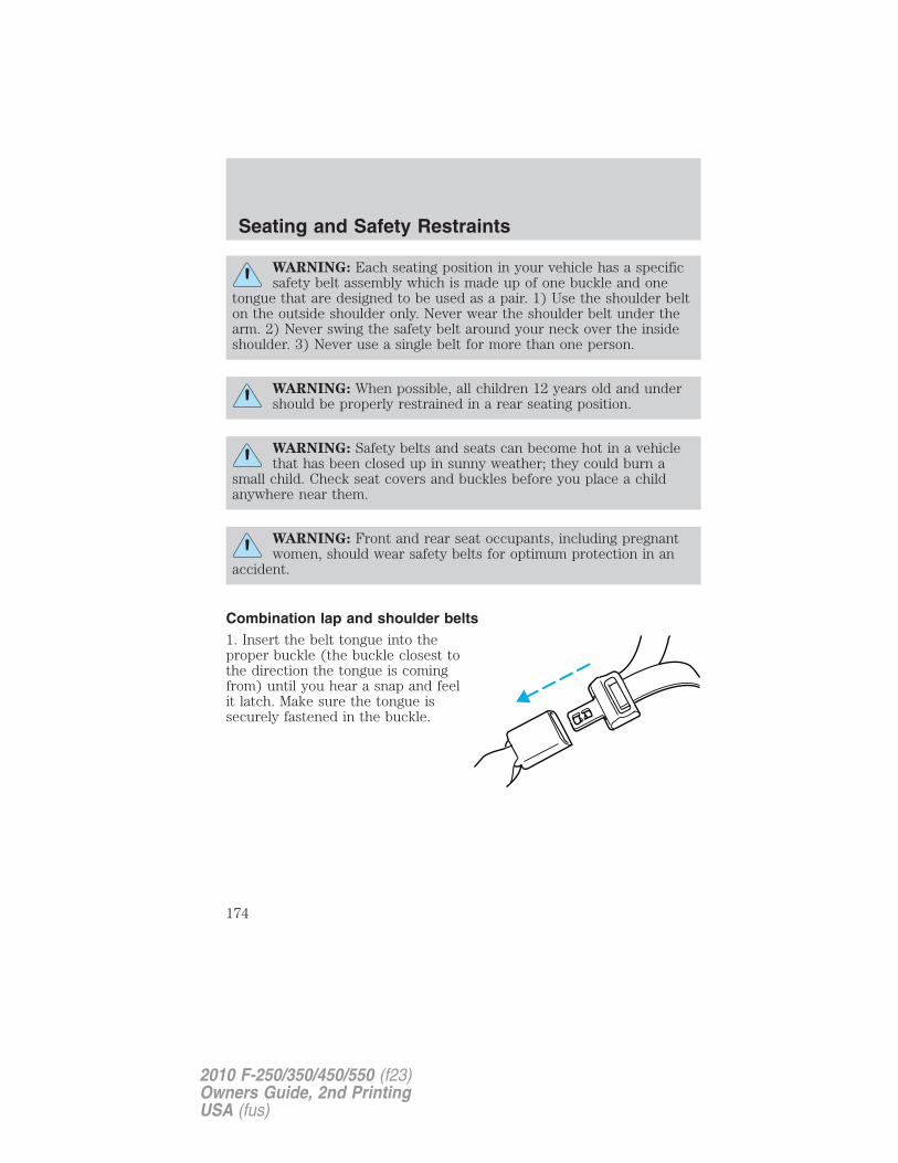
WARNING: Each seating position in your vehicle has a specificsafety belt assembly which is made up of one buckle and one
tongue that are designed to be used as a pair. 1) Use the shoulder belton the outside shoulder only. Never wear the shoulder belt under thearm. 2) Never swing the safety belt around your neck over the insideshoulder. 3) Never use a single belt for more than one person.
WARNING: When possible, all children 12 years old and undershould be properly restrained in a rear seating position.
WARNING: Safety belts and seats can become hot in a vehiclethat has been closed up in sunny weather; they could burn a
small child. Check seat covers and buckles before you place a childanywhere near them.
WARNING: Front and rear seat occupants, including pregnantwomen, should wear safety belts for optimum protection in an
accident.
Combination lap and shoulder belts1. Insert the belt tongue into theproper buckle (the buckle closest tothe direction the tongue is comingfrom) until you hear a snap and feelit latch. Make sure the tongue issecurely fastened in the buckle.
Seating and Safety Restraints
174
2010 F-250/350/450/550 (f23)Owners Guide, 2nd PrintingUSA (fus)
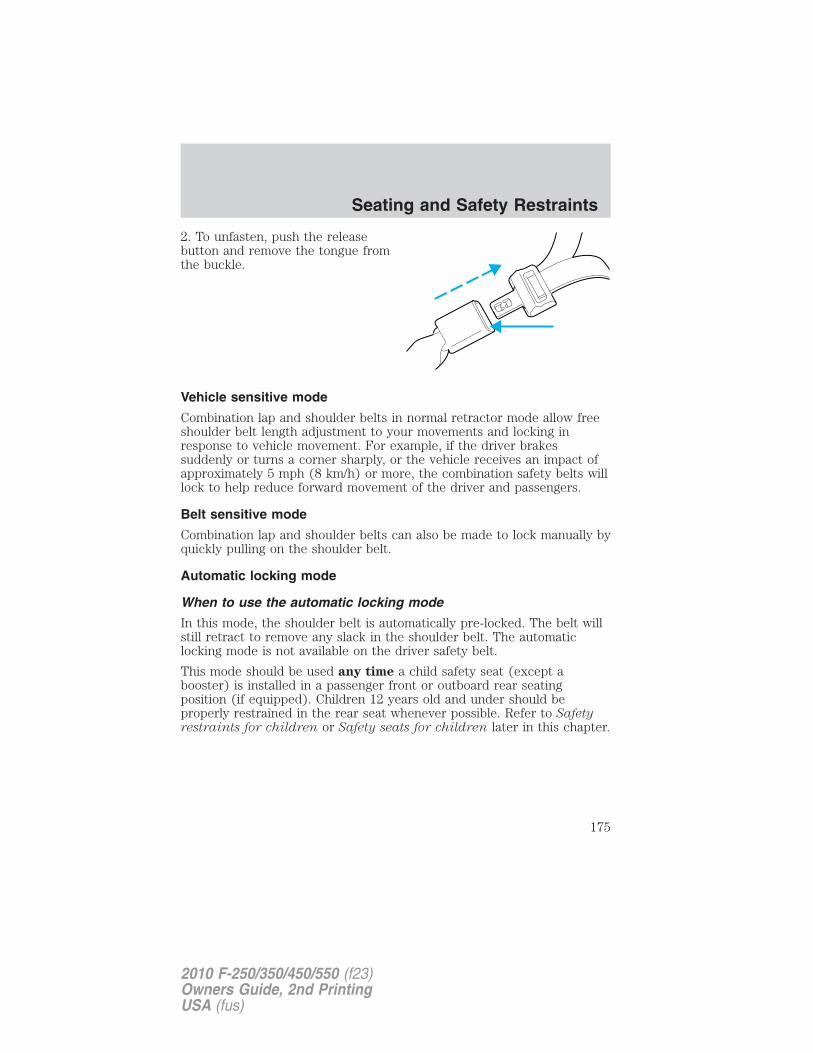
2. To unfasten, push the releasebutton and remove the tongue fromthe buckle.
Vehicle sensitive mode
Combination lap and shoulder belts in normal retractor mode allow freeshoulder belt length adjustment to your movements and locking inresponse to vehicle movement. For example, if the driver brakessuddenly or turns a corner sharply, or the vehicle receives an impact ofapproximately 5 mph (8 km/h) or more, the combination safety belts willlock to help reduce forward movement of the driver and passengers.
Belt sensitive mode
Combination lap and shoulder belts can also be made to lock manually byquickly pulling on the shoulder belt.
Automatic locking mode
When to use the automatic locking mode
In this mode, the shoulder belt is automatically pre-locked. The belt willstill retract to remove any slack in the shoulder belt. The automaticlocking mode is not available on the driver safety belt.
This mode should be used any time a child safety seat (except abooster) is installed in a passenger front or outboard rear seatingposition (if equipped). Children 12 years old and under should beproperly restrained in the rear seat whenever possible. Refer to Safetyrestraints for children or Safety seats for children later in this chapter.
Seating and Safety Restraints
175
2010 F-250/350/450/550 (f23)Owners Guide, 2nd PrintingUSA (fus)
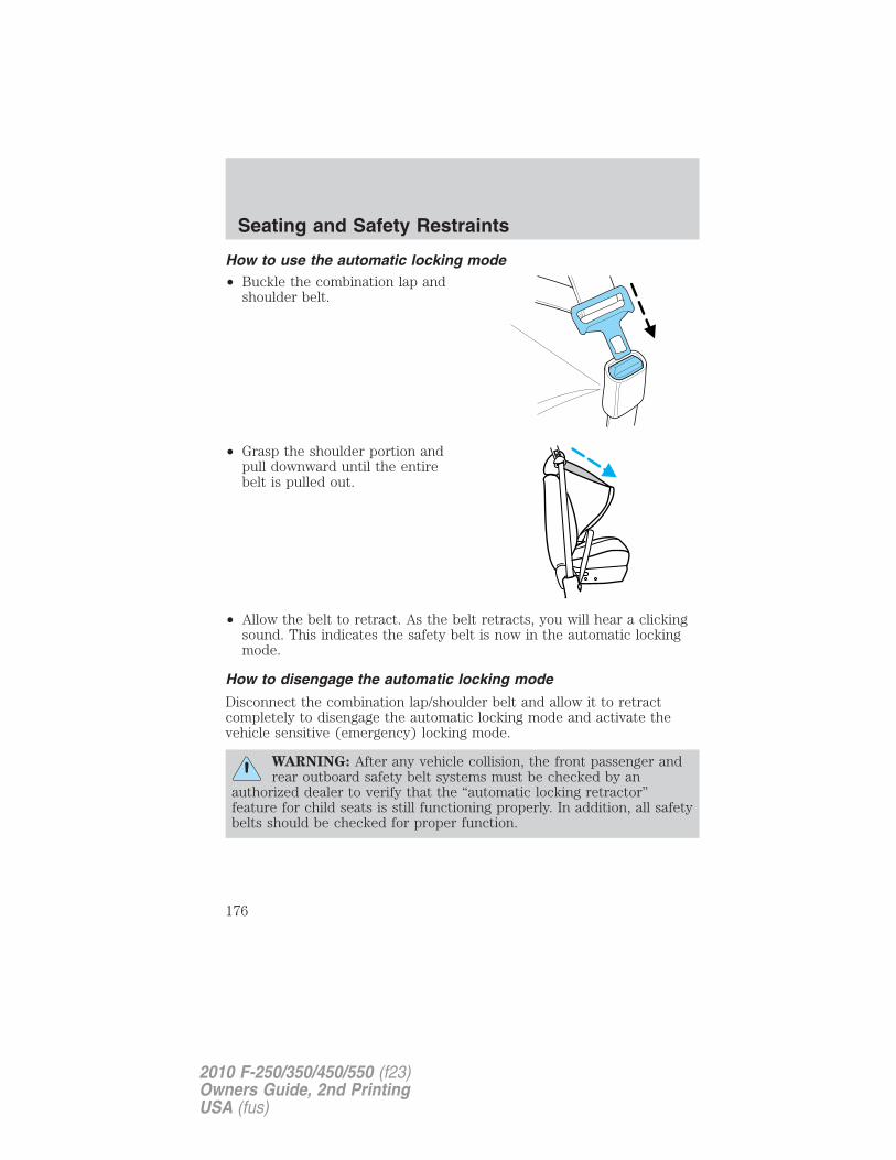
How to use the automatic locking mode• Buckle the combination lap and
shoulder belt.
• Grasp the shoulder portion andpull downward until the entirebelt is pulled out.
• Allow the belt to retract. As the belt retracts, you will hear a clickingsound. This indicates the safety belt is now in the automatic lockingmode.
How to disengage the automatic locking mode
Disconnect the combination lap/shoulder belt and allow it to retractcompletely to disengage the automatic locking mode and activate thevehicle sensitive (emergency) locking mode.
WARNING: After any vehicle collision, the front passenger andrear outboard safety belt systems must be checked by an
authorized dealer to verify that the “automatic locking retractor”feature for child seats is still functioning properly. In addition, all safetybelts should be checked for proper function.
Seating and Safety Restraints
176
2010 F-250/350/450/550 (f23)Owners Guide, 2nd PrintingUSA (fus)
WARNING: BELT AND RETRACTOR ASSEMBLY MUST BEREPLACED if the safety belt assembly “automatic locking
retractor” feature or any other safety belt function is not operatingproperly when checked by an authorized dealer. Failure to replace thebelt and retractor assembly could increase the risk of injury incollisions.
Energy management feature• This vehicle has a safety belt system with an energy management
feature at the front outboard seating positions to help further reducethe risk of injury in the event of a head-on collision.
• The front outboard safety belt systems have a retractor assembly thatis designed to pay out webbing in a controlled manner. This feature isdesigned to help reduce the belt force acting on the occupant’s chest.
Safety belt pretensionerYour vehicle is equipped with safety belt retractor pretensioners at thedriver and front outboard passenger seating positions.
The driver and front outboard passenger safety belt pretensioners aredesigned to activate only during certain frontal or near-frontal collisionswith sufficient longitudinal deceleration. A safety belt pretensioner is adevice which tightens the webbing of the lap and shoulder belts duringsome collisions in such a way that they fit more snugly against the body.
The driver and front outboard passenger safety belt system (includingretractors, buckles and height adjusters) must be replaced if the vehicleis involved in a collision that results in the activation of the safety beltpretensioners. Refer to the Child restraint and safety beltmaintenance section in this chapter.
WARNING: Failure to replace the safety belt assembly underthe above conditions could result in severe personal injuries in
the event of a collision.
Front safety belt height adjustmentThe front outboard seating positions are equipped with safety belt heightadjusters.
Adjust the height of the shoulder belt so the belt rests across the middleof your shoulder.
Seating and Safety Restraints
177
2010 F-250/350/450/550 (f23)Owners Guide, 2nd PrintingUSA (fus)
WARNING: Position the safety belt height adjusters so that thebelt rests across the middle of your shoulder. Failure to adjust
the safety belt properly could reduce the effectiveness of the seat beltand increase the risk of injury in a collision.
To adjust the shoulder belt height,push the button and slide the heightadjuster up or down. Release thebutton and pull down on the heightadjuster to make sure it is locked inplace.
Safety belt with cinch tongue (Regular cab center seating positionand Super Cab/Crew Cab rear center seating positions)The cinch tongue will slide up and down the belt webbing when the beltis stowed or while putting safety belts on. When the lap/shoulder safetybelt is buckled, the cinch tongue will allow the lap portion to beshortened, but pinches the webbing to keep the lap portion from gettinglonger. The cinch tongue is designed to slip during a crash, so alwayswear the shoulder belt properly and don’t allow any slack in either thelap or shoulder portions.
Before you can reach and latch a combination lap and shoulder belthaving a cinch tongue into the buckle, you may have to lengthen the lapbelt portion of it.
1. To lengthen the lap belt, pullsome webbing out of the shoulderbelt retractor.
2. While holding the webbing belowthe tongue, grasp the tip (metalportion) of the tongue so that it isparallel to the webbing and slide thetongue upward.
3. Provide enough lap belt length so that the tongue can reach thebuckle.
Seating and Safety Restraints
178
2010 F-250/350/450/550 (f23)Owners Guide, 2nd PrintingUSA (fus)
How to fasten the cinch tongue (Regular cab center seatingposition and Super Cab/Crew Cab rear center seating positions)
1. Pull the combination lap and shoulder belt from the retractor so thatthe shoulder belt portion of the safety belt crosses your shoulder andchest.
2. Be sure the belt is not twisted. If the belt is twisted, remove the twist.
3. Insert the belt tongue into the proper buckle for your seating positionuntil you hear a snap and feel it latch.
4. Make sure the tongue is securely fastened to the buckle by pulling onthe tongue.
WARNING: The lap belt should fit snugly and as low as possiblearound the hips, not across the waist.
While you are fastened in the safety belt, the combination lap/shoulderbelt with a cinch tongue adjusts to your movement. However, if youbrake hard, turn hard, or if your vehicle receives an impact of 5 mph(8 km/h) or more, the safety belt will become locked and help reduceyour forward movement.
Lap belts
Adjusting the lap belt
WARNING: The lap belt should fit snugly and as low as possiblearound the hips, not across the waist.
• 1st row center seating position on SuperCab and Crew Cab
The lap belt does not adjust automatically.
Seating and Safety Restraints
179
2010 F-250/350/450/550 (f23)Owners Guide, 2nd PrintingUSA (fus)
Insert the tongue into the correctbuckle (the buckle closest to thedirection the tongue is comingfrom). To lengthen the belt, turn thetongue at a right angle to the beltand pull across your lap until itreaches the buckle. To tighten thebelt, pull the loose end of the beltthrough the tongue until it fitssnugly across the hips.
Shorten and fasten the belt whennot in use.
Safety belt warning light and indicator chime
The safety belt warning light illuminates in the instrument cluster and achime sounds to remind the occupants to fasten their safety belts.
Seating and Safety Restraints
180
2010 F-250/350/450/550 (f23)Owners Guide, 2nd PrintingUSA (fus)
Conditions of operation
If... Then...
The driver’s safety belt is notbuckled before the ignition switchis turned to the on position...
The safety belt warning lightilluminates 1-2 minutes and thewarning chime sounds4-8 seconds.
The driver’s safety belt is buckledwhile the indicator light isilluminated and the warning chimeis sounding...
The safety belt warning light andwarning chime turn off.
The driver’s safety belt is buckledbefore the ignition switch is turnedto the on position...
The safety belt warning light andindicator chime remain off.
Belt-Minder�The Belt-Minder� feature is a supplemental warning to the safety beltwarning function. This feature provides additional reminders to thedriver that the driver’s safety belt is unbuckled by intermittentlysounding a chime and illuminating the safety belt warning lamp in theinstrument cluster.
If... Then...
The driver’s safety belt is notbuckled before the vehicle hasreached at least 3 mph (5 km/h)and 1-2 minutes have elapsedsince the ignition switch has beenturned to the on position...
The Belt-Minder� feature isactivated - the safety belt warninglight illuminates and the warningchime sounds for six secondsevery 30 seconds, repeating forapproximately five minutes or untilsafety belt is buckled.
The driver’s safety belt is buckledwhile the safety belt indicator lightis illuminated and the safety beltwarning chime is sounding...
The Belt-Minder� feature will notactivate.
The driver’s safety belt is buckledbefore the ignition switch is turnedto the on position...
The Belt-Minder� feature will notactivate.
Seating and Safety Restraints
181
2010 F-250/350/450/550 (f23)Owners Guide, 2nd PrintingUSA (fus)
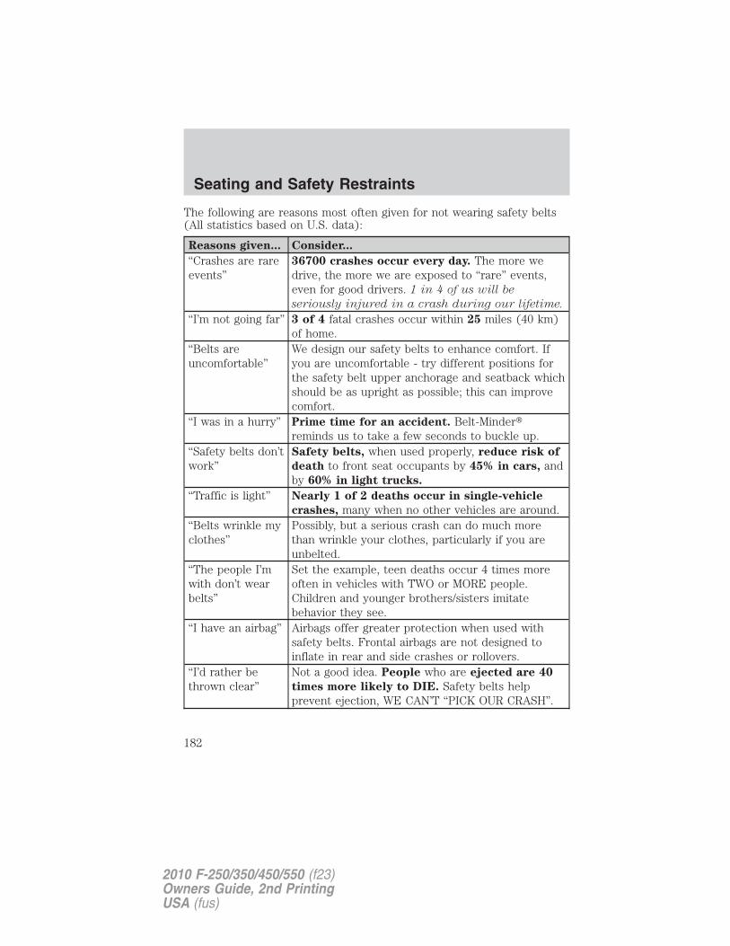
The following are reasons most often given for not wearing safety belts(All statistics based on U.S. data):
Reasons given... Consider...
“Crashes are rareevents”
36700 crashes occur every day. The more wedrive, the more we are exposed to “rare” events,even for good drivers. 1 in 4 of us will be
seriously injured in a crash during our lifetime.
“I’m not going far” 3 of 4 fatal crashes occur within 25 miles (40 km)of home.
“Belts areuncomfortable”
We design our safety belts to enhance comfort. Ifyou are uncomfortable - try different positions forthe safety belt upper anchorage and seatback whichshould be as upright as possible; this can improvecomfort.
“I was in a hurry” Prime time for an accident. Belt-Minder�reminds us to take a few seconds to buckle up.
“Safety belts don’twork”
Safety belts, when used properly, reduce risk of
death to front seat occupants by 45% in cars, andby 60% in light trucks.
“Traffic is light” Nearly 1 of 2 deaths occur in single-vehicle
crashes, many when no other vehicles are around.“Belts wrinkle myclothes”
Possibly, but a serious crash can do much morethan wrinkle your clothes, particularly if you areunbelted.
“The people I’mwith don’t wearbelts”
Set the example, teen deaths occur 4 times moreoften in vehicles with TWO or MORE people.Children and younger brothers/sisters imitatebehavior they see.
“I have an airbag” Airbags offer greater protection when used withsafety belts. Frontal airbags are not designed toinflate in rear and side crashes or rollovers.
“I’d rather bethrown clear”
Not a good idea. People who are ejected are 40
times more likely to DIE. Safety belts helpprevent ejection, WE CAN’T “PICK OUR CRASH”.
Seating and Safety Restraints
182
2010 F-250/350/450/550 (f23)Owners Guide, 2nd PrintingUSA (fus)
WARNING: Do not sit on top of a buckled safety belt or insert alatchplate into the buckle to avoid the Belt-Minder� chime. To
do so may adversely affect the performance of the vehicle’s airbagsystem.
One-time disableAny time the safety belt is buckled and then unbuckled during anignition on cycle, the Belt-Minder� will be disabled for that ignition cycleonly.
Deactivating/activating the Belt-Minder� feature (Driver only)The Belt-Minder� feature can be deactivated/activated by performing thefollowing procedure:
Before following the procedure, make sure that the following conditionsare met:
• the parking brake is set
• the gearshift is in P (Park)
• the ignition switch is in the off position
• all vehicle doors are closed
• the driver’s safety belt is unbuckled
• the parklamps/headlamps are in the off position
WARNING: While the design allows you to deactivate yourBelt-Minder�, this system is designed to improve your chances of
being safely belted and surviving an accident. We recommend youleave the Belt-Minder� system activated for yourself and others whomay use the vehicle. To reduce the risk of injury, do notdeactivate/activate the Belt-Minder� feature while driving the vehicle.
Belt-Minder� activation and deactivation procedure
1. Turn the ignition switch to the on position. (DO NOT START THEENGINE)
2. Wait until the safety belt warning light turns off. (approximately oneminute)
• Step 3 must be completed within 60 seconds after the safety beltwarning light turns off.
Seating and Safety Restraints
183
2010 F-250/350/450/550 (f23)Owners Guide, 2nd PrintingUSA (fus)
3. Buckle then unbuckle the safety belt nine times at a moderate speed,ending with the safety belt in the unbuckled state.
• After Step 3 is complete, the safety belt warning light will be turnedon for three seconds.
• If Step 4 does not occur within 10 seconds at the end of Step 3,Belt-Minder� will automatically exit programming mode withoutchanging its enable status.
4. Within 7 seconds of the light turning on, at a moderate speed, bucklethen unbuckle the safety belt.
• This will disable the Belt-Minder� feature if it is currently enabled. Asconfirmation, the safety belt warning light will flash four times persecond for three seconds.
• This will enable the Belt-Minder� feature if it is currently disabled. Asconfirmation, the safety belt warning light will flash four times persecond for three seconds, followed by three seconds with the light off,then followed by the safety belt warning light flashing four times persecond for three seconds again.
5. After receiving confirmation, the deactivation/activation procedure iscomplete.
Safety belt extension assembly
If the safety belt is too short when fully extended, there is an 8 inch(20 cm) safety belt extension assembly that can be added (part number611C22). This assembly can be obtained from an authorized dealer.
Use only extensions manufactured by the same supplier as the safetybelt. Manufacturer identification is located at the end of the webbing onthe label. Also, use the safety belt extension only if the safety belt is tooshort for you when fully extended.
WARNING: Do not use extensions to change the fit of theshoulder belt across the torso.
Seating and Safety Restraints
184
2010 F-250/350/450/550 (f23)Owners Guide, 2nd PrintingUSA (fus)
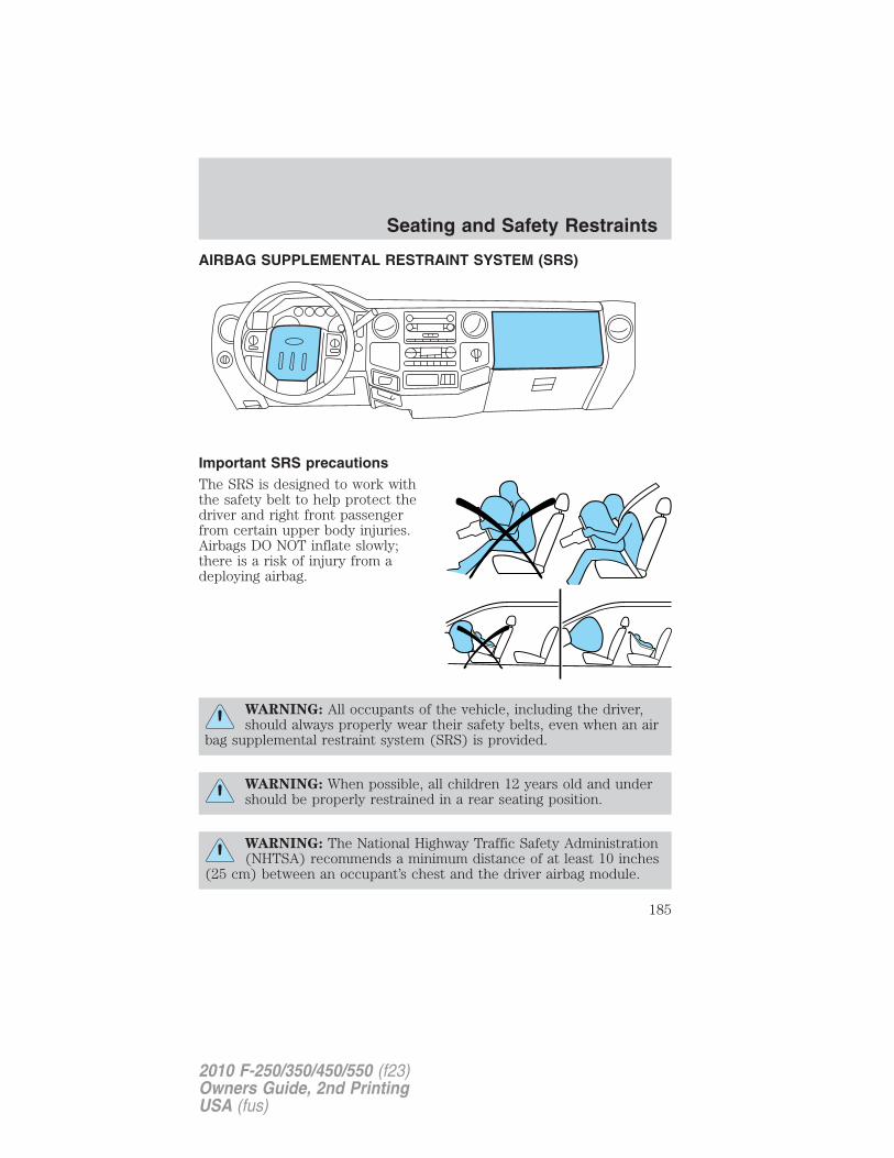
AIRBAG SUPPLEMENTAL RESTRAINT SYSTEM (SRS)
Important SRS precautionsThe SRS is designed to work withthe safety belt to help protect thedriver and right front passengerfrom certain upper body injuries.Airbags DO NOT inflate slowly;there is a risk of injury from adeploying airbag.
WARNING: All occupants of the vehicle, including the driver,should always properly wear their safety belts, even when an air
bag supplemental restraint system (SRS) is provided.
WARNING: When possible, all children 12 years old and undershould be properly restrained in a rear seating position.
WARNING: The National Highway Traffic Safety Administration(NHTSA) recommends a minimum distance of at least 10 inches
(25 cm) between an occupant’s chest and the driver airbag module.
Seating and Safety Restraints
185
2010 F-250/350/450/550 (f23)Owners Guide, 2nd PrintingUSA (fus)
WARNING: Never place your arm over the airbag module as adeploying airbag can result in serious arm fractures or other
injuries.
To properly position yourself away from the airbag:• Move your seat to the rear as far as you can while still reaching the
pedals comfortably.• Recline the seat slightly one or two degrees from the upright position.
WARNING: Do not put anything on or over the airbag module.Placing objects on or over the airbag inflation area may cause
those objects to be propelled by the airbag into your face and torsocausing serious injury.
WARNING: Do not attempt to service, repair, or modify theairbag supplemental restraint systems or its fuses. Contact your
authorized dealer as soon as possible.
WARNING: The front passenger airbag is not designed to offerprotection to an occupant in the center front seating position.
WARNING: Modifying or adding equipment to the front end ofthe vehicle (including frame, bumper, front end body structure
and tow hooks) may affect the performance of the airbag system,increasing the risk of injury. Do not modify the front end of thevehicle.
WARNING: Additional equipment such as snowplow equipmentmay effect the performance of the airbag sensors increasing the
risk of injury. Please refer to the Body Builders Layout Book forinstructions about the appropriate installation of additional equipment.
Children and airbagsFor additional important safety information, read all information onsafety restraints in this guide.
Children must always be properly restrained. Failure to follow theseinstructions may increase the risk of injury in a collision.
Seating and Safety Restraints
186
2010 F-250/350/450/550 (f23)Owners Guide, 2nd PrintingUSA (fus)
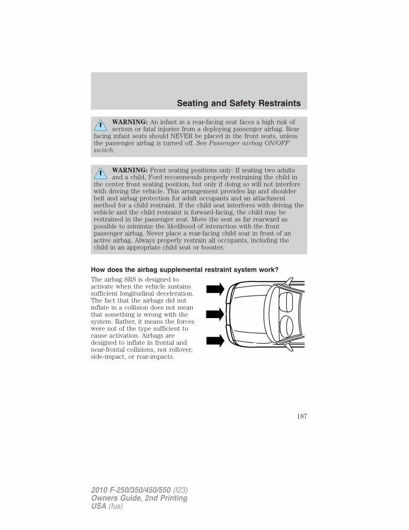
WARNING: An infant in a rear-facing seat faces a high risk ofserious or fatal injuries from a deploying passenger airbag. Rear
facing infant seats should NEVER be placed in the front seats, unlessthe passenger airbag is turned off. See Passenger airbag ON/OFFswitch.
WARNING: Front seating positions only: If seating two adultsand a child, Ford recommends properly restraining the child in
the center front seating position, but only if doing so will not interferewith driving the vehicle. This arrangement provides lap and shoulderbelt and airbag protection for adult occupants and an attachmentmethod for a child restraint. If the child seat interferes with driving thevehicle and the child restraint is forward-facing, the child may berestrained in the passenger seat. Move the seat as far rearward aspossible to minimize the likelihood of interaction with the frontpassenger airbag. Never place a rear-facing child seat in front of anactive airbag. Always properly restrain all occupants, including thechild in an appropriate child seat or booster.
How does the airbag supplemental restraint system work?The airbag SRS is designed toactivate when the vehicle sustainssufficient longitudinal deceleration.The fact that the airbags did notinflate in a collision does not meanthat something is wrong with thesystem. Rather, it means the forceswere not of the type sufficient tocause activation. Airbags aredesigned to inflate in frontal andnear-frontal collisions, not rollover,side-impact, or rear-impacts.
Seating and Safety Restraints
187
2010 F-250/350/450/550 (f23)Owners Guide, 2nd PrintingUSA (fus)
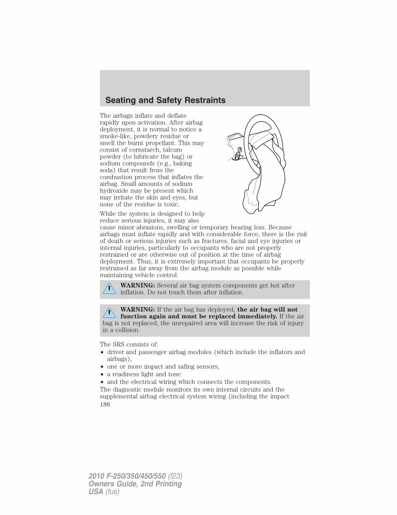
The airbags inflate and deflaterapidly upon activation. After airbagdeployment, it is normal to notice asmoke-like, powdery residue orsmell the burnt propellant. This mayconsist of cornstarch, talcumpowder (to lubricate the bag) orsodium compounds (e.g., bakingsoda) that result from thecombustion process that inflates theairbag. Small amounts of sodiumhydroxide may be present whichmay irritate the skin and eyes, butnone of the residue is toxic.
While the system is designed to helpreduce serious injuries, it may alsocause minor abrasions, swelling or temporary hearing loss. Becauseairbags must inflate rapidly and with considerable force, there is the riskof death or serious injuries such as fractures, facial and eye injuries orinternal injuries, particularly to occupants who are not properlyrestrained or are otherwise out of position at the time of airbagdeployment. Thus, it is extremely important that occupants be properlyrestrained as far away from the airbag module as possible whilemaintaining vehicle control.
WARNING: Several air bag system components get hot afterinflation. Do not touch them after inflation.
WARNING: If the air bag has deployed, the air bag will notfunction again and must be replaced immediately. If the air
bag is not replaced, the unrepaired area will increase the risk of injuryin a collision.
The SRS consists of:• driver and passenger airbag modules (which include the inflators and
airbags),• one or more impact and safing sensors,• a readiness light and tone• and the electrical wiring which connects the components.The diagnostic module monitors its own internal circuits and thesupplemental airbag electrical system wiring (including the impact
Seating and Safety Restraints
188
2010 F-250/350/450/550 (f23)Owners Guide, 2nd PrintingUSA (fus)

sensors), the system wiring, the airbag system readiness light, the airbagback up power and the airbag ignitors.
Determining if the system is operational
The SRS uses a readiness light in the instrument cluster or a tone toindicate the condition of the system. Refer to the Warning lights andchimes section in the Instrument Cluster chapter. Routine maintenanceof the airbag is not required.
A difficulty with the system is indicated by one or more of the following:
• The readiness light will eitherflash or stay lit.
• The readiness light will notilluminate immediately afterignition is turned on.
• A series of five beeps will be heard. The tone pattern will repeatperiodically until the problem and/or light are repaired.
If any of these things happen, even intermittently, contact yourauthorized dealer as soon as possible. Unless serviced, the system maynot function properly in the event of a collision.
SOS Post-Crash Alert System™
The system automatically flashes the turn signal lamps and sounds thehorn three times at four second intervals in the event of a serious impactthat deploys an airbag (front, side, side curtain or Safety Canopy�) orthe safety belt pretensioners.
The system can be turned off when any one of the following actions aretaken by the driver or any other person:
• pressing the hazard control button,
• or pressing the panic button on the remote entry transmitter.
The feature will continue to operate until the vehicle runs out of power.
Disposal of airbags and airbag equipped vehicles
See authorized dealer. Airbags MUST BE disposed of by qualifiedpersonnel.
Seating and Safety Restraints
189
2010 F-250/350/450/550 (f23)Owners Guide, 2nd PrintingUSA (fus)
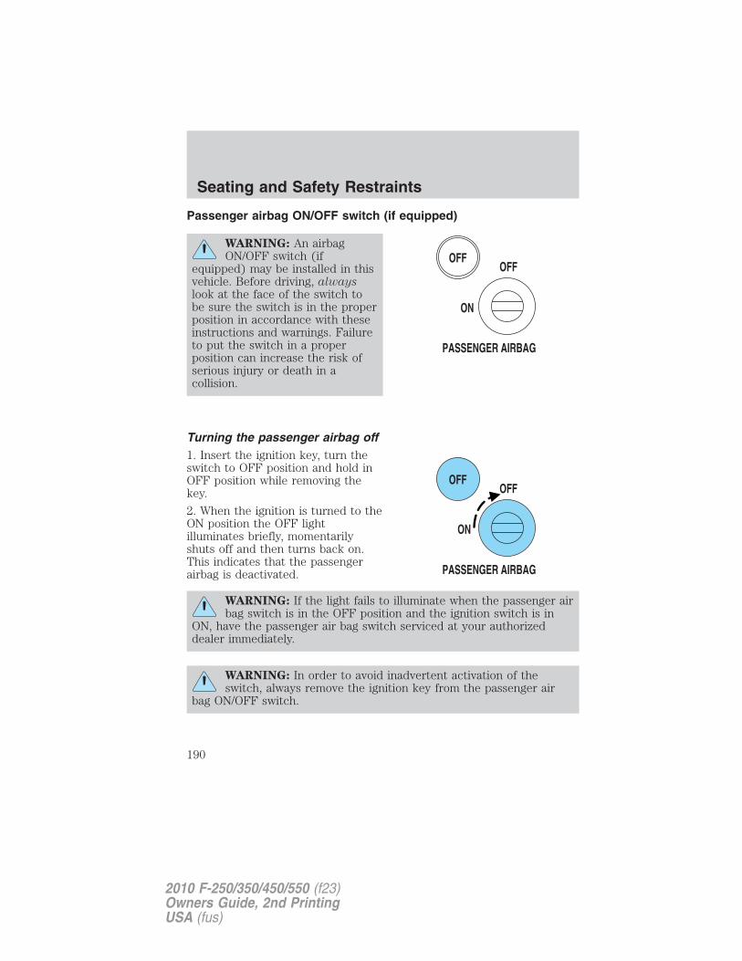
Passenger airbag ON/OFF switch (if equipped)
WARNING: An airbagON/OFF switch (if
equipped) may be installed in thisvehicle. Before driving, alwayslook at the face of the switch tobe sure the switch is in the properposition in accordance with theseinstructions and warnings. Failureto put the switch in a properposition can increase the risk ofserious injury or death in acollision.
Turning the passenger airbag off1. Insert the ignition key, turn theswitch to OFF position and hold inOFF position while removing thekey.
2. When the ignition is turned to theON position the OFF lightilluminates briefly, momentarilyshuts off and then turns back on.This indicates that the passengerairbag is deactivated.
WARNING: If the light fails to illuminate when the passenger airbag switch is in the OFF position and the ignition switch is in
ON, have the passenger air bag switch serviced at your authorizeddealer immediately.
WARNING: In order to avoid inadvertent activation of theswitch, always remove the ignition key from the passenger air
bag ON/OFF switch.
Seating and Safety Restraints
190
2010 F-250/350/450/550 (f23)Owners Guide, 2nd PrintingUSA (fus)
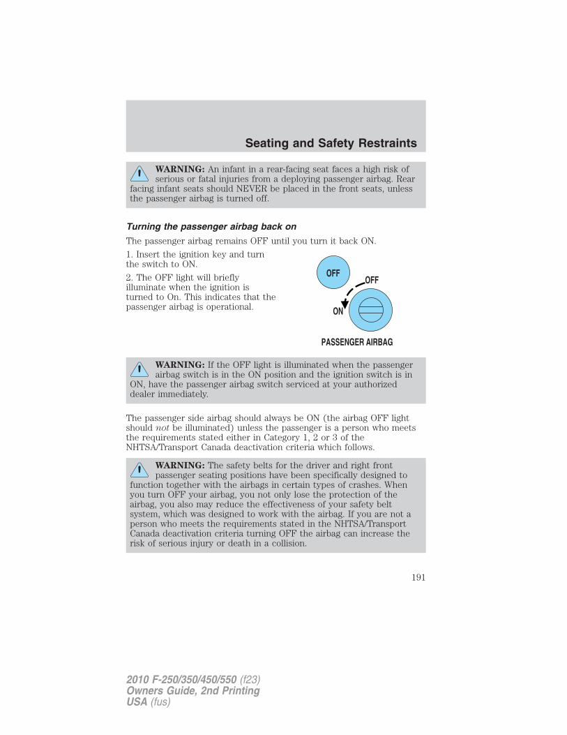
WARNING: An infant in a rear-facing seat faces a high risk ofserious or fatal injuries from a deploying passenger airbag. Rear
facing infant seats should NEVER be placed in the front seats, unlessthe passenger airbag is turned off.
Turning the passenger airbag back on
The passenger airbag remains OFF until you turn it back ON.
1. Insert the ignition key and turnthe switch to ON.
2. The OFF light will brieflyilluminate when the ignition isturned to On. This indicates that thepassenger airbag is operational.
WARNING: If the OFF light is illuminated when the passengerairbag switch is in the ON position and the ignition switch is in
ON, have the passenger airbag switch serviced at your authorizeddealer immediately.
The passenger side airbag should always be ON (the airbag OFF lightshould not be illuminated) unless the passenger is a person who meetsthe requirements stated either in Category 1, 2 or 3 of theNHTSA/Transport Canada deactivation criteria which follows.
WARNING: The safety belts for the driver and right frontpassenger seating positions have been specifically designed to
function together with the airbags in certain types of crashes. Whenyou turn OFF your airbag, you not only lose the protection of theairbag, you also may reduce the effectiveness of your safety beltsystem, which was designed to work with the airbag. If you are not aperson who meets the requirements stated in the NHTSA/TransportCanada deactivation criteria turning OFF the airbag can increase therisk of serious injury or death in a collision.
Seating and Safety Restraints
191
2010 F-250/350/450/550 (f23)Owners Guide, 2nd PrintingUSA (fus)
WARNING: If your vehicle has rear seats, always transportchildren who are 12 and younger in the rear seat. Always use
safety belts and child restraints properly. DO NOT place a child in arear facing infant seat in the front seat unless your vehicle is equippedwith an airbag ON/OFF switch and the passenger airbag is turned OFF.This is because the back of the infant seat is too close to the inflatingairbag and the risk of a fatal injury to the infant when the airbaginflates is substantial.
The vast majority of drivers and passengers are much safer with anairbag than without. To do their job and reduce the risk of lifethreatening injuries, airbags must open with great force, and this forcecan pose a potentially deadly risk in some situations, particularly when afront seat occupant is not properly buckled up. The most effective wayto reduce the risk of unnecessary airbag injuries without reducing theoverall safety of the vehicle is to make sure all occupants are properlyrestrained in the vehicle, especially in the front seat. This provides theprotection of safety belts and permits the airbags to provide theadditional protection they were designed to provide. If you choose todeactivate your airbag, you are losing the very significant risk reducingbenefits of the airbag and you are also reducing the effectiveness of thesafety belts, because safety belts in modern vehicles are designed towork as a safety system with the airbags.Read all airbag warning labels in the vehicle as well as the otherimportant airbag instructions and warnings in this Owner’s Guide.
NHTSA deactivation criteria (excluding Canada)1. Infant. An infant (less than 1 year old) must ride in the front seatbecause:• the vehicle has no rear seat;• the vehicle has a rear seat too small to accommodate a rear-facing
infant seat; or• the infant has a medical condition which, according to the infant’s
physician, makes it necessary for the infant to ride in the front so thatthe driver can constantly monitor the child’s condition.
2. Child age 1 to 12. A child age 1 to 12 must ride in the front seatbecause:
• the vehicle has no rear seat;
• although children ages 1 to 12 ride in the rear seat(s) wheneverpossible, children ages 1 to 12 sometimes must ride in the frontbecause no space is available in the rear seat(s) of the vehicle; or
Seating and Safety Restraints
192
2010 F-250/350/450/550 (f23)Owners Guide, 2nd PrintingUSA (fus)
• the child has a medical condition which, according to the child’sphysician, makes it necessary for the child to ride in the front seat sothat the driver can constantly monitor the child’s condition.
3. Medical condition. A passenger has a medical condition which,according to his or her physician:
• causes the passenger airbag to pose a special risk for the passenger;and
• makes the potential harm from the passenger airbag in a crash greaterthan the potential harm from turning OFF the airbag and allowing thepassenger, even if belted, to hit the dashboard or windshield in acrash.
WARNING: This vehicle has special energy management safetybelts for the driver and right front passenger. These particular
belts are specifically designed to work with airbags to help reduce therisk of injury in a collision. The energy management safety belt isdesigned to give or release additional belt webbing in some accidentsto reduce concentration of force on an occupant’s chest and reduce therisk of certain bone fractures and injuries to underlying organs. In acrash, if the airbag is turned OFF, this energy management safety beltmight permit the person wearing the belt to move forward enough toincur a serious or fatal injury. The more severe the crash, and theheavier the occupant, the greater the risk is. Be sure the airbag isturned ON for any person who does not qualify under the NHTSAdeactivation criteria.
Transport Canada deactivation criteria (Canada Only)1. Infant: An infant (less than 1 year old) must ride in the front seatbecause:
• my vehicle has no rear seat;
• the rear seat in my vehicle cannot accommodate a rear-facing infantseat; or
• the infant has a medical condition which, according to the infant’sphysician, makes it necessary for the infant to ride in the front seat sothat the driver can monitor the infant’s condition.
Seating and Safety Restraints
193
2010 F-250/350/450/550 (f23)Owners Guide, 2nd PrintingUSA (fus)
2. Child age 12 or under: A child age 12 or under must ride in thefront seat because:
• my vehicle has no rear seat;
• although children age 12 and under ride in the rear seat wheneverpossible, children age 12 and under have no option but to sometimesride in the front seat because rear seat space is insufficient; or
• the child has a medical condition that, according to the child’sphysician, makes it necessary for the child to ride in the front seat sothat the driver can monitor the child’s condition.
3. Medical condition: A passenger has a medical condition that,according to his or her physician:
• poses a special risk for the passenger if the airbag deploys; and
• makes the potential harm from the passenger airbag deploymentgreater than the potential harm from turning OFF the airbag andexperiencing a crash without the protection offered by the airbag
WARNING: This vehicle has special energy management safetybelts for the driver and right front passenger. These particular
belts are specifically designed to work with airbags to help reduce therisk of injury in a collision. The energy management safety belt isdesigned to give or release additional belt webbing in some accidentsto reduce concentration of force on an occupant’s chest and reduce therisk of certain bone fractures and injuries to underlying organs. In acrash, if the airbag is turned OFF, this energy management safety beltmight permit the person wearing the belt to move forward enough toincur a serious or fatal injury. The more severe the crash, and theheavier the occupant, the greater the risk is. Be sure the airbag isturned ON for any person who does not qualify under the NHTSAdeactivation criteria.
Seating and Safety Restraints
194
2010 F-250/350/450/550 (f23)Owners Guide, 2nd PrintingUSA (fus)
SAFETY RESTRAINTS FOR CHILDRENSee the following sections for directions on how to properly use safetyrestraints for children. Also see Airbag supplemental restraint system(SRS) in this chapter for special instructions about using airbags.
Important child restraint precautions
WARNING: Always make sure your child is secured properly ina device that is appropriate for their height, age and weight.
Child safety restraints must be purchased separately from the vehicle.Failure to follow these instructions and guidelines may result in anincreased risk of serious injury or death to your child.
WARNING: All children are shaped differently. TheRecommendations for Safety Restraints are based on probable
child height, age and weight thresholds from NHTSA and other safetyorganizations or are the minimum requirements of law. Fordrecommends checking with a NHTSA Certified Child Passenger SafetyTechnician (CPST) and your pediatrician to make sure your child seatis appropriate for your child, and is compatible with and properlyinstalled in the vehicle. To locate a child seat fitting station and CPSTcontact the NHTSA toll free at 1-888-327-4236 or on the internet athttp://www.nhtsa.dot.gov. Failure to properly restrain children in safetyseats made especially for their height, age, and weight may result in anincreased risk of serious injury or death to your child.
Seating and Safety Restraints
195
2010 F-250/350/450/550 (f23)Owners Guide, 2nd PrintingUSA (fus)
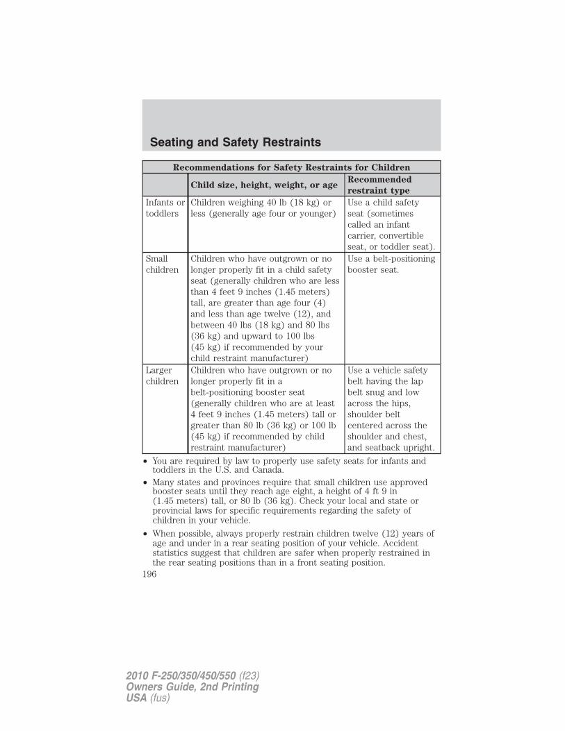
Recommendations for Safety Restraints for Children
Child size, height, weight, or ageRecommended
restraint type
Infants ortoddlers
Children weighing 40 lb (18 kg) orless (generally age four or younger)
Use a child safetyseat (sometimescalled an infantcarrier, convertibleseat, or toddler seat).
Smallchildren
Children who have outgrown or nolonger properly fit in a child safetyseat (generally children who are lessthan 4 feet 9 inches (1.45 meters)tall, are greater than age four (4)and less than age twelve (12), andbetween 40 lbs (18 kg) and 80 lbs(36 kg) and upward to 100 lbs(45 kg) if recommended by yourchild restraint manufacturer)
Use a belt-positioningbooster seat.
Largerchildren
Children who have outgrown or nolonger properly fit in abelt-positioning booster seat(generally children who are at least4 feet 9 inches (1.45 meters) tall orgreater than 80 lb (36 kg) or 100 lb(45 kg) if recommended by childrestraint manufacturer)
Use a vehicle safetybelt having the lapbelt snug and lowacross the hips,shoulder beltcentered across theshoulder and chest,and seatback upright.
• You are required by law to properly use safety seats for infants andtoddlers in the U.S. and Canada.
• Many states and provinces require that small children use approvedbooster seats until they reach age eight, a height of 4 ft 9 in(1.45 meters) tall, or 80 lb (36 kg). Check your local and state orprovincial laws for specific requirements regarding the safety ofchildren in your vehicle.
• When possible, always properly restrain children twelve (12) years ofage and under in a rear seating position of your vehicle. Accidentstatistics suggest that children are safer when properly restrained inthe rear seating positions than in a front seating position.
Seating and Safety Restraints
196
2010 F-250/350/450/550 (f23)Owners Guide, 2nd PrintingUSA (fus)
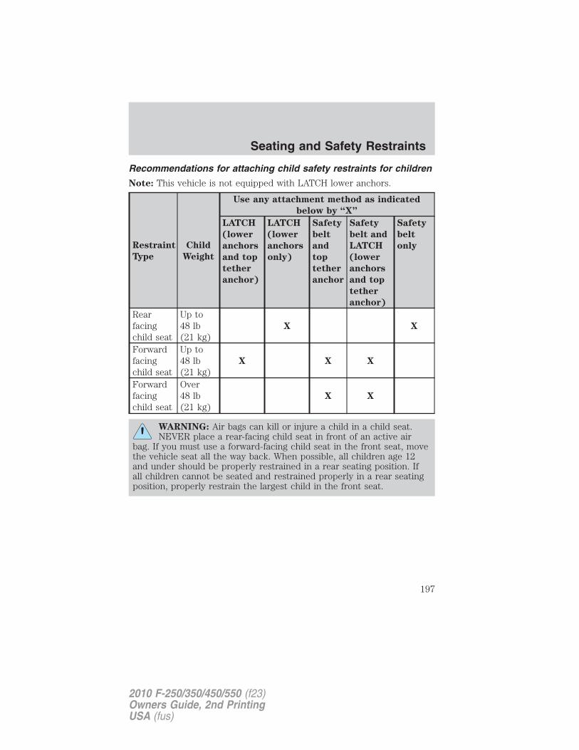
Recommendations for attaching child safety restraints for children
Note: This vehicle is not equipped with LATCH lower anchors.
Restraint
Type
Child
Weight
Use any attachment method as indicated
below by “X”
LATCH
(lower
anchors
and top
tether
anchor)
LATCH
(lower
anchors
only)
Safety
belt
and
top
tether
anchor
Safety
belt and
LATCH
(lower
anchors
and top
tether
anchor)
Safety
belt
only
Rearfacingchild seat
Up to48 lb(21 kg)
X X
Forwardfacingchild seat
Up to48 lb(21 kg)
X X X
Forwardfacingchild seat
Over48 lb(21 kg)
X X
WARNING: Air bags can kill or injure a child in a child seat.NEVER place a rear-facing child seat in front of an active air
bag. If you must use a forward-facing child seat in the front seat, movethe vehicle seat all the way back. When possible, all children age 12and under should be properly restrained in a rear seating position. Ifall children cannot be seated and restrained properly in a rear seatingposition, properly restrain the largest child in the front seat.
Seating and Safety Restraints
197
2010 F-250/350/450/550 (f23)Owners Guide, 2nd PrintingUSA (fus)
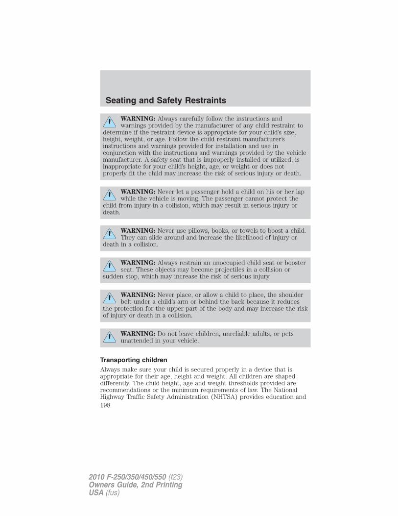
WARNING: Always carefully follow the instructions andwarnings provided by the manufacturer of any child restraint to
determine if the restraint device is appropriate for your child’s size,height, weight, or age. Follow the child restraint manufacturer’sinstructions and warnings provided for installation and use inconjunction with the instructions and warnings provided by the vehiclemanufacturer. A safety seat that is improperly installed or utilized, isinappropriate for your child’s height, age, or weight or does notproperly fit the child may increase the risk of serious injury or death.
WARNING: Never let a passenger hold a child on his or her lapwhile the vehicle is moving. The passenger cannot protect the
child from injury in a collision, which may result in serious injury ordeath.
WARNING: Never use pillows, books, or towels to boost a child.They can slide around and increase the likelihood of injury or
death in a collision.
WARNING: Always restrain an unoccupied child seat or boosterseat. These objects may become projectiles in a collision or
sudden stop, which may increase the risk of serious injury.
WARNING: Never place, or allow a child to place, the shoulderbelt under a child’s arm or behind the back because it reduces
the protection for the upper part of the body and may increase the riskof injury or death in a collision.
WARNING: Do not leave children, unreliable adults, or petsunattended in your vehicle.
Transporting childrenAlways make sure your child is secured properly in a device that isappropriate for their age, height and weight. All children are shapeddifferently. The child height, age and weight thresholds provided arerecommendations or the minimum requirements of law. The NationalHighway Traffic Safety Administration (NHTSA) provides education and
Seating and Safety Restraints
198
2010 F-250/350/450/550 (f23)Owners Guide, 2nd PrintingUSA (fus)
training to ensure that all children ages 0 to 16 are properly restrained inthe correct restraint system. Ford recommends checking with a NHTSACertified Child Passenger Safety Technician (CPST) and yourpediatrician to make sure your seat is appropriate for your child andproperly installed in the vehicle. To locate a child seat fitting station andCPST contact the NHTSA toll free at 1-888-327-4236 or on the internetat http://www.nhtsa.dot.gov.
Follow all the safety restraint and airbag precautions that apply to adultpassengers in your vehicle.
If the child is the proper height, age, and weight (as specified by yourchild safety seat or booster manufacturer), fits the restraint and can berestrained properly, then restrain the child in the child safety seat orwith the belt-positioning booster. Remember that child seats andbelt-positioning boosters vary and may be designed to fit children ofdifferent heights, ages and weights. Children who are too large for childsafety seats or belt-positioning boosters (as specified by your child safetyseat manufacturer) should always properly wear safety belts.
SAFETY SEATS FOR CHILDREN
Infant and/or toddler seatsUse a safety seat that is recommended for the size and weight of thechild.
When installing a child safety seat:
• Review and follow the informationpresented in the Airbagsupplemental restraint system(SRS) section in this chapter.
• Carefully follow all of themanufacturer’s instructionsincluded with the safety seat youput in your vehicle. If you do notinstall and use the safety seatproperly, the child may be injuredin a sudden stop or collision.
Airbags can kill or injure a child in a child seat. NEVER place arear-facing child seat in front of an active airbag. If you must use aforward-facing child seat in the front seat, move the vehicle seat all theway back.
Seating and Safety Restraints
199
2010 F-250/350/450/550 (f23)Owners Guide, 2nd PrintingUSA (fus)
Children 12 and under should be properly restrained in a rear seatingposition whenever possible. If all children cannot be seated andrestrained properly in a rear seating position, properly restrain thelargest child in the front seat.
Installing child safety seats with automatic locking modecombination lap and shoulder belts(front passenger and rear outboard seating positions)Check to make sure the child seat is properly secured before each use.Children 12 and under should be properly restrained in a rear seatingposition whenever possible. If all children cannot be seated andrestrained properly in a rear seating position, properly restrain thelargest child in the front seat.
When installing a child safety seat with combination lap/shoulder belts:
• Use the correct safety belt buckle for that seating position.
• Insert the belt tongue into the proper buckle until you hear a snapand feel it latch. Make sure the tongue is securely fastened in thebuckle.
• Keep the buckle release button pointing up and away from the safetyseat, with the tongue between the child seat and the release button,to prevent accidental unbuckling.
• Place vehicle seat back in upright position.
• This vehicle does not require the use of a locking clip.
WARNING: Depending on where you secure a child restraint,and depending on the child restraint design, you may block
access to certain safety belt buckle assemblies and/or LATCH loweranchors, rendering those features potentially unusable. To avoid risk ofinjury, occupants should only use seating positions where they are ableto be properly restrained.
Seating and Safety Restraints
200
2010 F-250/350/450/550 (f23)Owners Guide, 2nd PrintingUSA (fus)
Installing the child safety seat
Perform the following steps when installing the child seat in theoutboard combination lap/shoulder belts:
Note: Although the child seat illustrated is a forward facing child seat,the steps are the same for installing a rear facing child seat.
1. Position the child safety seat in aseat with a combination lap andshoulder belt.
WARNING: An airbag can kill or injure a child in a child seat.Child seats should NEVER be placed in the front seats, unless
the passenger airbag switch is turned off, See Passenger airbag on/offswitch.
WARNING: Rear facing child seats should NEVER be placed inthe front seats unless the passenger airbag switch is turned off.
2. Pull down on the shoulder beltand then grasp the shoulder beltand lap belt together.
Seating and Safety Restraints
201
2010 F-250/350/450/550 (f23)Owners Guide, 2nd PrintingUSA (fus)
3. While holding the shoulder andlap belt portions together, route thetongue through the child seataccording to the child seatmanufacturer’s instructions. Be surethe belt webbing is not twisted.
4. Insert the belt tongue into theproper buckle (the buckle closest tothe direction the tongue is comingfrom) for that seating position untilyou hear and feel the latch engage.Make sure the tongue is latchedsecurely by pulling on it.
5. Put the safety belt in theautomatic locking mode. To do so,grasp the shoulder portion of thebelt and pull downward until all ofthe belt is pulled out.
6. Allow the belt to retract to remove slack. The belt will click as itretracts to indicate it is in the automatic locking mode.
7. Try to pull the belt out of the retractor to make sure the retractor isin the automatic locking mode (you should not be able to pull more beltout). If the retractor is not locked, repeat Steps 5 and 6.
Seating and Safety Restraints
202
2010 F-250/350/450/550 (f23)Owners Guide, 2nd PrintingUSA (fus)
8. Remove remaining slack from thebelt. Force the seat down with extraweight, e.g., by pressing down orkneeling on the child restraint whilepulling up on the shoulder belt inorder to force slack from the belt.This is necessary to remove theremaining slack that will exist oncethe additional weight of the child isadded to the child restraint. It alsohelps to achieve the propersnugness of the child seat to thevehicle. Sometimes, a slight leantowards the buckle will additionallyhelp to remove remaining slack from the belt.
9. Attach the tether strap (if thechild seat is equipped). Refer toAttaching child safety seats withtether straps later in this chapter.
10. Before placing the child in theseat, forcibly move the seat forwardand back to make sure the seat issecurely held in place. To checkthis, grab the seat at the belt pathand attempt to move it side to sideand forward. There should be nomore than one inch (2.5 cm) of movement for proper installation.11. Ford recommends checking with a NHTSA Certified Child PassengerSafety Technician (CPST) to make certain the child restraint is properlyinstalled. In Canada, check with your local St. John Ambulance office forreferral to a CPST.
Installing child safety seats in cinch tongue combination lap andshoulder belt seating positions (Regular Cab front center andSuper/Crew cab rear center positions)The belt webbing below the tongue is the lap portion of the combinationlap/shoulder belt, and the belt webbing above the tongue is the shoulderbelt portion of the combination lap/shoulder belt.
WARNING: Always use both lap and shoulder safety belt in theRegular Cab center seating position if applicable.
Seating and Safety Restraints
203
2010 F-250/350/450/550 (f23)Owners Guide, 2nd PrintingUSA (fus)
Note: Although the child seat illustrated is a forward facing child seat,the steps are the same for installing a rear facing child seat.
1. Position the child safety seat inthe center seat.
WARNING: Airbags can kill or injure a child in a child seat. Ifyou must use a forward-facing child seat in the front seat, move
seat all the way back.
WARNING: Rear facing child seats should NEVER be placed infront of an active airbag.
2. Slide the tongue up the webbing.
3. While holding both shoulder andlap portions next to the tongue,route the tongue and webbingthrough the child seat according tothe child seat manufacturer’sinstructions. Be sure that the beltwebbing is not twisted.
Seating and Safety Restraints
204
2010 F-250/350/450/550 (f23)Owners Guide, 2nd PrintingUSA (fus)
4. Insert the belt tongue into theproper buckle for that seatingpositions until you hear a snap andfeel it latch. Make sure the tongue issecurely latched to the buckle bypulling on the tongue.
5. Remove remaining slack from thebelt. Force the seat down with extraweight, e.g., by pressing down orkneeling on the child restraint whilepulling up on the shoulder belt inorder to force slack from the belt.This is necessary to remove theremaining slack that will exist oncethe additional weight of the child isadded to the child restraint. It alsohelps to achieve the propersnugness of the child seat to the vehicle. Sometimes, a slight leantowards the buckle will additionally help to remove remaining slack fromthe belt.
6. Attach the tether strap (if the child seat is equipped). Refer toAttaching child safety seats with tether straps later in this chapter.
Seating and Safety Restraints
205
2010 F-250/350/450/550 (f23)Owners Guide, 2nd PrintingUSA (fus)
7. Before placing the child in theseat, forcibly move the seat forwardand back to make sure the seat issecurely held in place. To checkthis, grab the seat at the belt pathand attempt to move it side to sideand forward. There should be nomore than one inch (2.5 cm) ofmovement for proper installation.
8. Ford recommends checking with a NHTSA Certified Child PassengerSafety Technician (CPST) to make certain the child restraint is properlyinstalled. In Canada, check with your local St. John Ambulance office forreferral to a CPST.Installing child safety seats in the front row lap belt seatingpositions (Super Cab and Crew Cab)
WARNING: Installing a child safety seat in the front row lapseating position should be avoided if at all possible.
WARNING: Never place a rear-facing child seat in the frontcenter seating position of a vehicle with rear seating positions.
WARNING: Front seating positions only: If seating two adultsand a child, Ford recommends properly restraining the child in
the center front seating position, but only if doing so will not interferewith driving the vehicle. This arrangement provides lap and shoulderbelt and airbag protection for adult occupants and an attachmentmethod for a child restraint. If the child seat interferes with driving thevehicle and the child restraint is forward-facing, the child may berestrained in the passenger seat. Move the seat as far rearward aspossible to minimize the likelihood of interaction with the frontpassenger airbag. Never place a rear-facing child seat in front of anactive airbag. All occupants of the vehicle should always properly weartheir safety belts. Ensure the child is properly restrained in anappropriate child seat or with the use of a booster.
1. Lengthen the lap belt. To lengthen the belt, hold the tongue so that itsbottom is perpendicular to the direction of webbing while sliding thetongue up the webbing.
Seating and Safety Restraints
206
2010 F-250/350/450/550 (f23)Owners Guide, 2nd PrintingUSA (fus)
2. Place the child safety seat in the center seating position.3. Route the tongue and webbing through the child seat according to thechild seat manufacturer’s instructions.4. Insert the belt tongue into the proper buckle for the center seatingposition until you hear a snap and feel it latch. Make sure the tongue issecurely fastened to the buckle by pulling on the tongue.5. Push down on the child seat while pulling on the loose end of the lapbelt webbing to tighten the belt.
6. Before placing the child into the child seat, forcibly tilt the child seatfrom side to side and in forward direction to make sure that the seat issecurely held in place. To check this, grab the seat at the belt path andattempt to move it side to side and forward and back. There should beno more than one inch (2.5 cm) of movement for proper installation.
7. Ford recommends checking with a NHTSA Certified Child PassengerSafety Technician (CPST) to make certain the child restraint is properlyinstalled. In Canada, check with your local St. John Ambulance office forreferral to a CPST.
Note: For Super Cab and Crew Cab there is no top tether anchor for thefront center seating position. See Attaching child safety seats withtether straps later in this chapter.
Attaching child safety seats with LATCH(Lower Anchors and Tethers for CHildren) attachmentsThe LATCH system is composed of three vehicle anchor points: two (2)lower anchors located where the vehicle seat back and seat cushion meet(called the “seat bight”) and one (1) top tether anchor located behindthat seating position. Your vehicle is not equipped with the lower anchorpoints in the seat bight. For this vehicle use the vehicle safety belt andupper tether to secure a child seat. See Attaching child safety seatswith tether straps and Recommendations for attaching safetyrestraints for children in this chapter for more information.
Attaching child safety seats with tether strapsMany forward-facing child safety seats include a tether strap whichextends from the back of the child safety seat and hooks to an anchoringpoint called the top tether anchor. Tether straps are available as anaccessory for many older safety seats. Contact the manufacturer of yourchild seat for information about ordering a tether strap, or to obtain alonger tether strap if the tether strap on your safety seat does not reachthe appropriate top tether anchor in the vehicle.
Seating and Safety Restraints
207
2010 F-250/350/450/550 (f23)Owners Guide, 2nd PrintingUSA (fus)
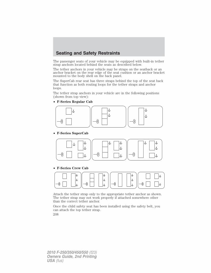
The passenger seats of your vehicle may be equipped with built-in tetherstrap anchors located behind the seats as described below.The tether anchors in your vehicle may be straps on the seatback or ananchor bracket on the rear edge of the seat cushion or an anchor bracketmounted to the body shell on the back panel.
The SuperCab rear seat has three straps behind the top of the seat backthat function as both routing loops for the tether straps and anchorloops.
The tether strap anchors in your vehicle are in the following positions(shown from top view):
• F-Series Regular Cab
• F-Series SuperCab
• F-Series Crew Cab
Attach the tether strap only to the appropriate tether anchor as shown.The tether strap may not work properly if attached somewhere otherthan the correct tether anchor.
Once the child safety seat has been installed using the safety belt, youcan attach the top tether strap.
Seating and Safety Restraints
208
2010 F-250/350/450/550 (f23)Owners Guide, 2nd PrintingUSA (fus)
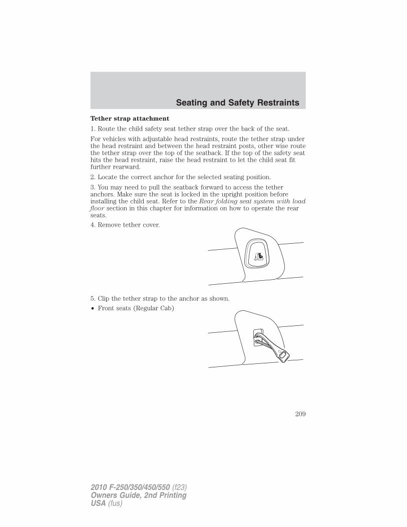
Tether strap attachment
1. Route the child safety seat tether strap over the back of the seat.
For vehicles with adjustable head restraints, route the tether strap underthe head restraint and between the head restraint posts, other wise routethe tether strap over the top of the seatback. If the top of the safety seathits the head restraint, raise the head restraint to let the child seat fitfurther rearward.
2. Locate the correct anchor for the selected seating position.
3. You may need to pull the seatback forward to access the tetheranchors. Make sure the seat is locked in the upright position beforeinstalling the child seat. Refer to the Rear folding seat system with loadfloor section in this chapter for information on how to operate the rearseats.
4. Remove tether cover.
5. Clip the tether strap to the anchor as shown.
• Front seats (Regular Cab)
Seating and Safety Restraints
209
2010 F-250/350/450/550 (f23)Owners Guide, 2nd PrintingUSA (fus)
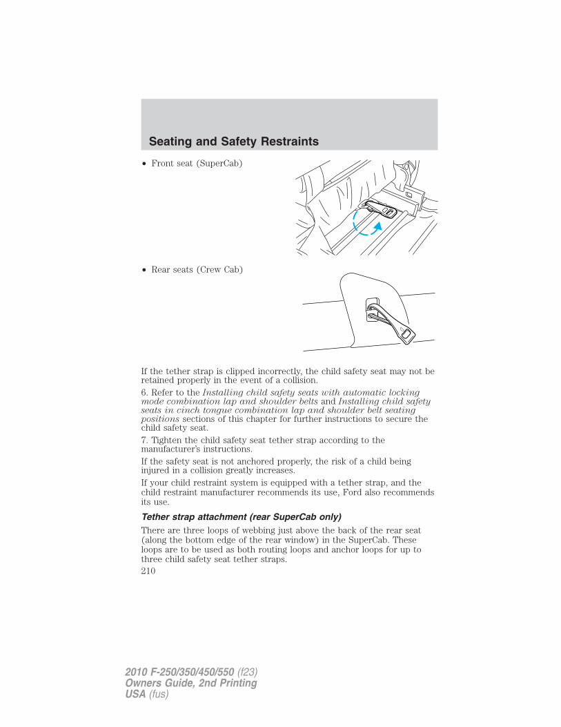
• Front seat (SuperCab)
• Rear seats (Crew Cab)
If the tether strap is clipped incorrectly, the child safety seat may not beretained properly in the event of a collision.6. Refer to the Installing child safety seats with automatic lockingmode combination lap and shoulder belts and Installing child safetyseats in cinch tongue combination lap and shoulder belt seatingpositions sections of this chapter for further instructions to secure thechild safety seat.7. Tighten the child safety seat tether strap according to themanufacturer’s instructions.If the safety seat is not anchored properly, the risk of a child beinginjured in a collision greatly increases.If your child restraint system is equipped with a tether strap, and thechild restraint manufacturer recommends its use, Ford also recommendsits use.
Tether strap attachment (rear SuperCab only)There are three loops of webbing just above the back of the rear seat(along the bottom edge of the rear window) in the SuperCab. Theseloops are to be used as both routing loops and anchor loops for up tothree child safety seat tether straps.
Seating and Safety Restraints
210
2010 F-250/350/450/550 (f23)Owners Guide, 2nd PrintingUSA (fus)
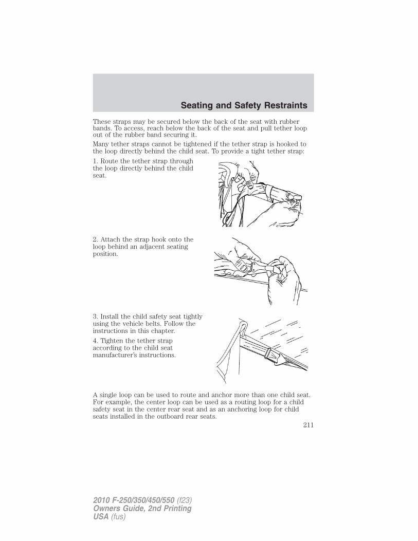
These straps may be secured below the back of the seat with rubberbands. To access, reach below the back of the seat and pull tether loopout of the rubber band securing it.Many tether straps cannot be tightened if the tether strap is hooked tothe loop directly behind the child seat. To provide a tight tether strap:
1. Route the tether strap throughthe loop directly behind the childseat.
2. Attach the strap hook onto theloop behind an adjacent seatingposition.
3. Install the child safety seat tightlyusing the vehicle belts. Follow theinstructions in this chapter.
4. Tighten the tether strapaccording to the child seatmanufacturer’s instructions.
A single loop can be used to route and anchor more than one child seat.For example, the center loop can be used as a routing loop for a childsafety seat in the center rear seat and as an anchoring loop for childseats installed in the outboard rear seats.
Seating and Safety Restraints
211
2010 F-250/350/450/550 (f23)Owners Guide, 2nd PrintingUSA (fus)
Child booster seatsThe belt-positioning booster (booster seat) is used to improve the fit ofthe vehicle safety belt. Children outgrow a typical child seat (e.g.,convertible or toddler seat) when they weigh about 40 lb (18 kg) and arearound four (4) years of age. Consult your child safety seat owner guidefor the weight, height, and age limits specific to your child safety seat.Keep your child in the child safety seat if it properly fits the child,remains appropriate for their weight, height and age AND if properlysecured to the vehicle.
Although the lap/shoulder belt will provide some protection, childrenwho have outgrown a typical child seat are still too small for lap/shoulderbelts to fit properly, and wearing an improperly fitted vehicle safety beltcould increase the risk of serious injury in a crash. To improve the fit ofboth the lap and shoulder belt on children who have outgrown childsafety seats, Ford Motor Company recommends use of a belt-positioningbooster.
Booster seats position a child so that vehicle lap/shoulder safety belts fitbetter. They lift the child up so that the lap belt rests low across the hipsand the knees bend comfortably at the edge of the cushion, whileminimizing slouching. Booster seats may also make the shoulder belt fitbetter and more comfortably. Try to keep the belt near the middle of theshoulder and across the center of the chest. Moving the child closer (afew centimeters or inches) to the center of the vehicle, but remaining inthe same seating position, may help provide a good shoulder belt fit.
When children should use booster seatsChildren need to use booster seats from the time they outgrow thetoddler seat until they are big enough for the vehicle seat andlap/shoulder belt to fit properly. Generally this is when they reach aheight of at least 4 feet 9 inches (1.45 meters) tall (around age eight toage twelve and between 40 lb (18 kg) and 80 lb (36 kg) or upward to100 lb (45 kg) if recommended by your child restraint manufacturer).Many state and provincial laws require that children use approvedbooster seats until they reach age eight, a height of 4 feet 9 inches(1.45 meters) tall, or 80 lb (36 kg).
Seating and Safety Restraints
212
2010 F-250/350/450/550 (f23)Owners Guide, 2nd PrintingUSA (fus)
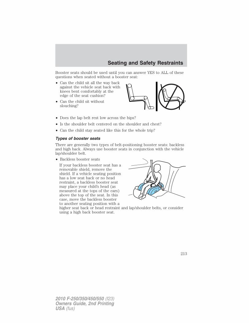
Booster seats should be used until you can answer YES to ALL of thesequestions when seated without a booster seat:
• Can the child sit all the way backagainst the vehicle seat back withknees bent comfortably at theedge of the seat cushion?
• Can the child sit withoutslouching?
• Does the lap belt rest low across the hips?
• Is the shoulder belt centered on the shoulder and chest?
• Can the child stay seated like this for the whole trip?
Types of booster seats
There are generally two types of belt-positioning booster seats: backlessand high back. Always use booster seats in conjunction with the vehiclelap/shoulder belt.
• Backless booster seats
If your backless booster seat has aremovable shield, remove theshield. If a vehicle seating positionhas a low seat back or no headrestraint, a backless booster seatmay place your child’s head (asmeasured at the tops of the ears)above the top of the seat. In thiscase, move the backless boosterto another seating position with ahigher seat back or head restraint and lap/shoulder belts, or considerusing a high back booster seat.
Seating and Safety Restraints
213
2010 F-250/350/450/550 (f23)Owners Guide, 2nd PrintingUSA (fus)
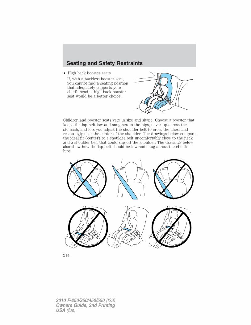
• High back booster seats
If, with a backless booster seat,you cannot find a seating positionthat adequately supports yourchild’s head, a high back boosterseat would be a better choice.
Children and booster seats vary in size and shape. Choose a booster thatkeeps the lap belt low and snug across the hips, never up across thestomach, and lets you adjust the shoulder belt to cross the chest andrest snugly near the center of the shoulder. The drawings below comparethe ideal fit (center) to a shoulder belt uncomfortably close to the neckand a shoulder belt that could slip off the shoulder. The drawings belowalso show how the lap belt should be low and snug across the child’ships.
Seating and Safety Restraints
214
2010 F-250/350/450/550 (f23)Owners Guide, 2nd PrintingUSA (fus)
If the booster seat slides on the vehicle seat, placing a rubberized meshsold as shelf or carpet liner under the booster seat may improve thiscondition. Do not introduce any item thicker than this under the boosterseat. Check with the booster seat manufacturer’s instructions.
The importance of shoulder beltsUsing a booster without a shoulder belt increases the risk of a child’shead hitting a hard surface in a collision. For this reason, you shouldnever use a booster seat with a lap belt only. It is generally best to use abooster seat with lap/shoulder belts in the back seat.
Move a child to a different seating location if the shoulder belt does notstay positioned on the shoulder during use.
Follow all instructions provided by the manufacturer of the booster seat.
WARNING: Never place, or allow a child to place, the shoulderbelt under a child’s arm or behind the back because it reduces
the protection for the upper part of the body and may increase the riskof injury or death in a collision.
Child restraint and safety belt maintenanceInspect the vehicle safety belts and child safety seat systems periodicallyto make sure they work properly and are not damaged. Inspect thevehicle and child seat safety belts to make sure there are no nicks, tearsor cuts. Replace if necessary. All vehicle safety belt assemblies, includingretractors, buckles, front safety belt buckle assemblies, buckle supportassemblies (slide bar-if equipped), shoulder belt height adjusters (ifequipped), shoulder belt guide on seatback (if equipped), child safetyseat LATCH and tether anchors, and attaching hardware, should beinspected after a collision. Refer to the child restraint manufacturer’sinstructions for additional inspection and maintenance informationspecific to the child restraint. Ford Motor Company recommends that allsafety belt assemblies in use in vehicles involved in a collision bereplaced. However, if the collision was minor and an authorized dealerfinds that the belts do not show damage and continue to operateproperly, they do not need to be replaced. Safety belt assemblies not inuse during a collision should also be inspected and replaced if eitherdamage or improper operation is noted.
Seating and Safety Restraints
215
2010 F-250/350/450/550 (f23)Owners Guide, 2nd PrintingUSA (fus)
For proper care of soiled safety belts, refer to Interior in the Cleaningchapter.
WARNING: Failure to inspect and if necessary replace thesafety belt assembly or child restraint system under the above
conditions could result in severe personal injuries in the event of acollision.
Seating and Safety Restraints
216
2010 F-250/350/450/550 (f23)Owners Guide, 2nd PrintingUSA (fus)
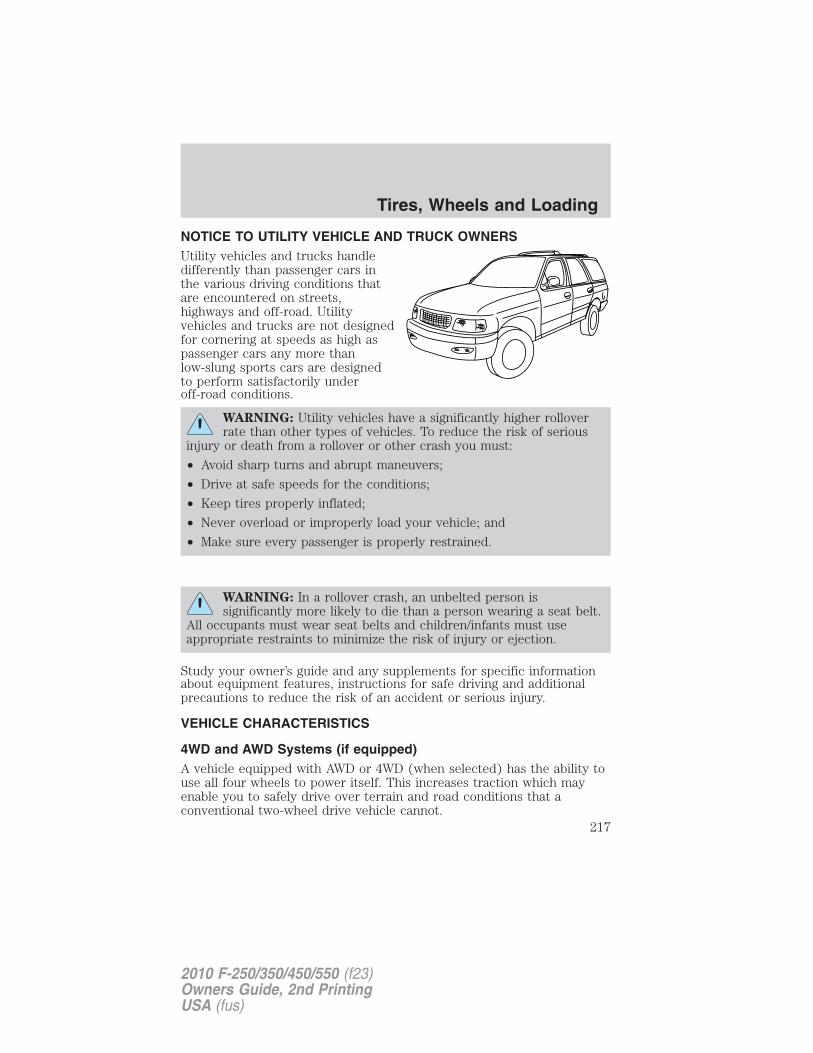
NOTICE TO UTILITY VEHICLE AND TRUCK OWNERSUtility vehicles and trucks handledifferently than passenger cars inthe various driving conditions thatare encountered on streets,highways and off-road. Utilityvehicles and trucks are not designedfor cornering at speeds as high aspassenger cars any more thanlow-slung sports cars are designedto perform satisfactorily underoff-road conditions.
WARNING: Utility vehicles have a significantly higher rolloverrate than other types of vehicles. To reduce the risk of serious
injury or death from a rollover or other crash you must:
• Avoid sharp turns and abrupt maneuvers;
• Drive at safe speeds for the conditions;
• Keep tires properly inflated;
• Never overload or improperly load your vehicle; and
• Make sure every passenger is properly restrained.
WARNING: In a rollover crash, an unbelted person issignificantly more likely to die than a person wearing a seat belt.
All occupants must wear seat belts and children/infants must useappropriate restraints to minimize the risk of injury or ejection.
Study your owner’s guide and any supplements for specific informationabout equipment features, instructions for safe driving and additionalprecautions to reduce the risk of an accident or serious injury.
VEHICLE CHARACTERISTICS
4WD and AWD Systems (if equipped)A vehicle equipped with AWD or 4WD (when selected) has the ability touse all four wheels to power itself. This increases traction which mayenable you to safely drive over terrain and road conditions that aconventional two-wheel drive vehicle cannot.
Tires, Wheels and Loading
217
2010 F-250/350/450/550 (f23)Owners Guide, 2nd PrintingUSA (fus)
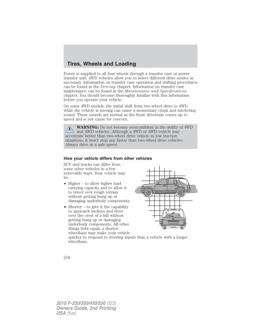
Power is supplied to all four wheels through a transfer case or powertransfer unit. 4WD vehicles allow you to select different drive modes asnecessary. Information on transfer case operation and shifting procedurescan be found in the Driving chapter. Information on transfer casemaintenance can be found in the Maintenance and Specificationschapter. You should become thoroughly familiar with this informationbefore you operate your vehicle.
On some 4WD models, the initial shift from two-wheel drive to 4WDwhile the vehicle is moving can cause a momentary clunk and ratchetingsound. These sounds are normal as the front drivetrain comes up tospeed and is not cause for concern.
WARNING: Do not become overconfident in the ability of 4WDand AWD vehicles. Although a 4WD or AWD vehicle may
accelerate better than two-wheel drive vehicle in low tractionsituations, it won’t stop any faster than two-wheel drive vehicles.Always drive at a safe speed.
How your vehicle differs from other vehiclesSUV and trucks can differ fromsome other vehicles in a fewnoticeable ways. Your vehicle maybe:
• Higher – to allow higher loadcarrying capacity and to allow itto travel over rough terrainwithout getting hung up ordamaging underbody components.
• Shorter – to give it the capabilityto approach inclines and driveover the crest of a hill withoutgetting hung up or damagingunderbody components. All otherthings held equal, a shorterwheelbase may make your vehiclequicker to respond to steering inputs than a vehicle with a longerwheelbase.
Tires, Wheels and Loading
218
2010 F-250/350/450/550 (f23)Owners Guide, 2nd PrintingUSA (fus)
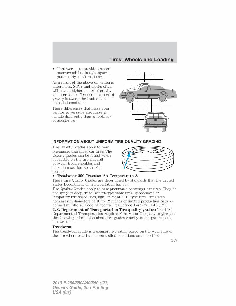
• Narrower — to provide greatermaneuverability in tight spaces,particularly in off-road use.
As a result of the above dimensionaldifferences, SUV’s and trucks oftenwill have a higher center of gravityand a greater difference in center ofgravity between the loaded andunloaded condition.
These differences that make yourvehicle so versatile also make ithandle differently than an ordinarypassenger car.
INFORMATION ABOUT UNIFORM TIRE QUALITY GRADINGTire Quality Grades apply to newpneumatic passenger car tires. TheQuality grades can be found whereapplicable on the tire sidewallbetween tread shoulder andmaximum section width. Forexample:• Treadwear 200 Traction AA Temperature A
These Tire Quality Grades are determined by standards that the UnitedStates Department of Transportation has set.Tire Quality Grades apply to new pneumatic passenger car tires. They donot apply to deep tread, winter-type snow tires, space-saver ortemporary use spare tires, light truck or “LT” type tires, tires withnominal rim diameters of 10 to 12 inches or limited production tires asdefined in Title 49 Code of Federal Regulations Part 575.104(c)(2).U.S. Department of Transportation-Tire quality grades: The U.S.Department of Transportation requires Ford Motor Company to give youthe following information about tire grades exactly as the governmenthas written it.TreadwearThe treadwear grade is a comparative rating based on the wear rate ofthe tire when tested under controlled conditions on a specified
Tires, Wheels and Loading
219
2010 F-250/350/450/550 (f23)Owners Guide, 2nd PrintingUSA (fus)
government test course. For example, a tire graded 150 would wear oneand one-half (11⁄2) times as well on the government course as a tiregraded 100. The relative performance of tires depends upon the actualconditions of their use, however, and may depart significantly from thenorm due to variations in driving habits, service practices, anddifferences in road characteristics and climate.Traction AA A B CThe traction grades, from highest to lowest are AA, A, B, and C. Thegrades represent the tire’s ability to stop on wet pavement as measuredunder controlled conditions on specified government test surfaces ofasphalt and concrete. A tire marked C may have poor tractionperformance.
WARNING: The traction grade assigned to this tire is based onstraight-ahead braking traction tests, and does not include
acceleration, cornering, hydroplaning or peak traction characteristics.
Temperature A B CThe temperature grades are A (the highest), B and C, representing thetire’s resistance to the generation of heat and its ability to dissipate heatwhen tested under controlled conditions on a specified indoor laboratorytest wheel. Sustained high temperature can cause the material of the tireto degenerate and reduce tire life, and excessive temperature can lead tosudden tire failure. The grade C corresponds to a level of performancewhich all passenger car tires must meet under the Federal Motor VehicleSafety Standard No. 139. Grades B and A represent higher levels ofperformance on the laboratory test wheel than the minimum required bylaw.
WARNING: The temperature grade for this tire is establishedfor a tire that is properly inflated and not overloaded. Excessive
speed, underinflation, or excessive loading, either separately or incombination, can cause heat buildup and possible tire failure.
TIRESTires are designed to give many thousands of miles of service, but theymust be maintained in order to get the maximum benefit from them.Glossary of tire terminology• Tire label: A label showing the OE (Original Equipment) tire sizes,
recommended inflation pressure and the maximum weight the vehiclecan carry.
Tires, Wheels and Loading
220
2010 F-250/350/450/550 (f23)Owners Guide, 2nd PrintingUSA (fus)
• Tire Identification Number (TIN): A number on the sidewall ofeach tire providing information about the tire brand andmanufacturing plant, tire size and date of manufacture. Also referredto as DOT code.
• Inflation pressure: A measure of the amount of air in a tire.
• Standard load: A class of P-metric or Metric tires designed to carry amaximum load at 35 psi [37 psi (2.5 bar) for Metric tires]. Increasingthe inflation pressure beyond this pressure will not increase the tire’sload carrying capability.
• Extra load: A class of P-metric or Metric tires designed to carry aheavier maximum load at 41 psi [43 psi (2.9 bar) for Metric tires].Increasing the inflation pressure beyond this pressure will not increasethe tire’s load carrying capability.
• kPa: Kilopascal, a metric unit of air pressure.
• PSI: Pounds per square inch, a standard unit of air pressure.
• Cold inflation pressure: The tire pressure when the vehicle hasbeen stationary and out of direct sunlight for an hour or more andprior to the vehicle being driven for 1 mile (1.6 km).
• Recommended inflation pressure: The cold inflation pressure foundon the Safety Compliance Certification Label or Tire Label located onthe B-Pillar or the edge of the driver’s door.
• B-pillar: The structural member at the side of the vehicle behind thefront door.
• Bead area of the tire: Area of the tire next to the rim.
• Sidewall of the tire: Area between the bead area and the tread.
• Tread area of the tire: Area of the perimeter of the tire thatcontacts the road when mounted on the vehicle.
• Rim: The metal support (wheel) for a tire or a tire and tube assemblyupon which the tire beads are seated.
INFLATING YOUR TIRESSafe operation of your vehicle requires that your tires are properlyinflated. Remember that a tire can lose up to half of its air pressurewithout appearing flat.
Every day before you drive, check your tires. If one looks lower than theothers, use a tire gauge to check pressure of all tires and adjust ifrequired.
Tires, Wheels and Loading
221
2010 F-250/350/450/550 (f23)Owners Guide, 2nd PrintingUSA (fus)
At least once a month and before long trips, inspect each tire and checkthe tire pressure with a tire gauge (including spare, if equipped). Inflateall tires to the inflation pressure recommended by Ford Motor Company.You are strongly urged to buy a reliable tire pressure gauge, as automaticservice station gauges may be inaccurate. Ford recommends the use of adigital or dial-type tire pressure gauge rather than a stick-type tirepressure gauge.
Use the recommended cold inflation pressure for optimum tireperformance and wear. Under-inflation or over-inflation may causeuneven treadwear patterns.
WARNING: Under-inflation is the most common cause of tirefailures and may result in severe tire cracking, tread separation
or �blowout�, with unexpected loss of vehicle control and increased riskof injury. Under-inflation increases sidewall flexing and rollingresistance, resulting in heat buildup and internal damage to the tire. Italso may result in unnecessary tire stress, irregular wear, loss ofvehicle control and accidents. A tire can lose up to half of its airpressure and not appear to be flat!
Always inflate your tires to the Ford recommended inflation pressureeven if it is less than the maximum inflation pressure information foundon the tire. The Ford recommended tire inflation pressure is found onthe Safety Compliance Certification Label or Tire Label which is locatedon the B-Pillar or the edge of the driver’s door. Failure to follow the tirepressure recommendations can cause uneven treadwear patterns andadversely affect the way your vehicle handles.
Note: Do not reduce tire pressure to change the ride characteristics ofthe vehicle. If you do not maintain the inflation pressure at the levelsspecified by Ford, your vehicle may experience a condition known as�shimmy�. Shimmy is a severe vibration and oscillation in the steeringwheel after the vehicle travels over a bump or dip in the road that doesnot dampen out by itself. Shimmy may result from significantunder-inflation of the tires, improper tires (load range, size, or type), orvehicle modifications such as lift-kits. In the event that your vehicleexperiences shimmy, you should slowly reduce speed by either lifting offthe accelerator pedal or lightly applying the brakes. The shimmy willcease as the vehicle speed decreases.
Maximum Permissible Inflation Pressure is the tire manufacturer’smaximum permissible pressure and/or the pressure at which themaximum load can be carried by the tire. This pressure is normally
Tires, Wheels and Loading
222
2010 F-250/350/450/550 (f23)Owners Guide, 2nd PrintingUSA (fus)
higher than the manufacturer’s recommended cold inflation pressurewhich can be found on the Safety Compliance Certification Label or TireLabel which is located on the B-Pillar or the edge of the driver’s door.The cold inflation pressure should never be set lower than therecommended pressure on the Safety Compliance Certification Label orTire Label.When weather temperature changes occur, tire inflation pressures alsochange. A 10°F (6°C) temperature drop can cause a corresponding dropof 1 psi (7 kPa) in inflation pressure. Check your tire pressuresfrequently and adjust them to the proper pressure which can be foundon the Safety Compliance Certification Label or Tire Label.To check the pressure in your tire(s):1. Make sure the tires are cool, meaning they are not hot from drivingeven a mile.If you are checking tire pressure when the tire is hot, (i.e. driven morethan 1 mile [1.6 km]), never “bleed” or reduce air pressure. The tires arehot from driving and it is normal for pressures to increase aboverecommended cold pressures. A hot tire at or below recommended coldinflation pressure could be significantly under-inflated.Note: If you have to drive a distance to get air for your tire(s), checkand record the tire pressure first and add the appropriate air pressurewhen you get to the pump. It is normal for tires to heat up and the airpressure inside to go up as you drive.2. Remove the cap from the valve on one tire, then firmly press the tiregauge onto the valve and measure the pressure.3. Add enough air to reach the recommended air pressure.Note: If you overfill the tire, release air by pushing on the metal stem inthe center of the valve. Then recheck the pressure with your tire gauge.4. Replace the valve cap.
5. Repeat this procedure for each tire, including the spare.
Note: Some spare tires operate at a higher inflation pressure than theother tires. For T-type/mini-spare tires (see the Dissimilar sparetire/wheel information section for description): Store and maintain at60 psi (4.15 bar). For Full Size and Dissimilar spare tires (see theDissimilar spare tire/wheel information section for description): Storeand maintain at the higher of the front and rear inflation pressure asshown on the Tire Label.
6. Visually inspect the tires to make sure there are no nails or otherobjects embedded that could poke a hole in the tire and cause an airleak.
Tires, Wheels and Loading
223
2010 F-250/350/450/550 (f23)Owners Guide, 2nd PrintingUSA (fus)
7. Check the sidewalls to make sure there are no gouges, cuts or bulges.
Tire inflation information
All tires with Steel Carcass Plies (if equipped):
This type of tire utilizes steel cords in the sidewalls. As such, theycannot be treated like normal light truck tires. Tire service, includingadjusting tire pressure, must be performed by personnel trained,supervised and equipped according to Federal Occupational Safety andHealth Administration (OSHA) regulations. For example, during anyprocedure involving tire inflation, the technician or individual mustutilize a remote inflation device, and ensure that all persons are clear ofthe trajectory area.
WARNING: An inflated tire and rim can be very dangerous ifimproperly used, serviced or maintained. To reduce the risk of
serious injury, never attempt to re-inflate a tire which has been run flator seriously under-inflated without first removing the tire from thewheel assembly for inspection. Do not attempt to add air to tires orreplace tires or wheels without first taking precautions to protectpersons and property.
Tires, Wheels and Loading
224
2010 F-250/350/450/550 (f23)Owners Guide, 2nd PrintingUSA (fus)
WARNING: Stay out of the trajectory (1) as indicated in theillustration.
TIRE CARE
Inspecting your tires and wheel valve stemsPeriodically inspect the tire treads for uneven or excessive wear andremove objects such as stones, nails or glass that may be wedged in thetread grooves. Check the tire and valve stems for holes, cracks, or cutsthat may permit air leakage and repair or replace the tire and replacethe valve stem. Inspect the tire sidewalls for cracking, cuts, bruises andother signs of damage or excessive wear. If internal damage to the tire issuspected, have the tire demounted and inspected in case it needs to berepaired or replaced. For your safety, tires that are damaged or showsigns of excessive wear should not be used because they are more likelyto blow out or fail.
Tires, Wheels and Loading
225
2010 F-250/350/450/550 (f23)Owners Guide, 2nd PrintingUSA (fus)
Improper or inadequate vehicle maintenance can cause tires to wearabnormally. Inspect all your tires, including the spare, frequently, andreplace them if one or more of the following conditions exist:
Tire wearWhen the tread is worn down to1/16th of an inch (2 mm), tires mustbe replaced to help prevent yourvehicle from skidding andhydroplaning. Built-in treadwearindicators, or “wear bars”, whichlook like narrow strips of smoothrubber across the tread will appearon the tire when the tread is worndown to 1/16th of an inch (2 mm).When the tire tread wears down tothe same height as these “wear bars”, the tire is worn out and must bereplaced.
DamagePeriodically inspect the tire treads and sidewalls for damage (such asbulges in the tread or sidewalls, cracks in the tread groove andseparation in the tread or sidewall). If damage is observed or suspectedhave the tire inspected by a tire professional. Tires can be damagedduring off-road use, so inspection after off-road use is alsorecommended.
WARNING: AgeTires degrade over time depending on many factors such as
weather, storage conditions, and conditions of use (load, speed,inflation pressure, etc.) the tires experience throughout their lives.In general, tires should be replaced after six years regardless of treadwear. However, heat caused by hot climates or frequent high loadingconditions can accelerate the aging process and may require tires to bereplaced more frequently.You should replace your spare tire when you replace the road tires orafter six years due to aging even if it has not been used.
Tires, Wheels and Loading
226
2010 F-250/350/450/550 (f23)Owners Guide, 2nd PrintingUSA (fus)
U.S. DOT Tire Identification Number (TIN)Both U.S. and Canada Federal regulations require tire manufacturers toplace standardized information on the sidewall of all tires. Thisinformation identifies and describes the fundamental characteristics ofthe tire and also provides a U.S. DOT Tire Identification Number forsafety standard certification and in case of a recall.
This begins with the letters “DOT” and indicates that the tire meets allfederal standards. The next two numbers or letters are the plant codedesignating where it was manufactured, the next two are the tire sizecode and the last four numbers represent the week and year the tire wasbuilt. For example, the numbers 317 mean the 31st week of 1997. After2000 the numbers go to four digits. For example, 2501 means the 25thweek of 2001. The numbers in between are identification codes used fortraceability. This information is used to contact customers if a tire defectrequires a recall.
Tire Replacement RequirementsYour vehicle is equipped with tires designed to provide a safe ride andhandling capability.
WARNING: Only use replacement tires and wheels that are thesame size, load index, speed rating and type (such as P-metric
versus LT-metric or all-season versus all-terrain) as those originallyprovided by Ford. The recommended tire and wheel size may be foundon either the Safety Compliance Certification Label or the Tire Labelwhich is located on the B-Pillar or edge of the driver’s door. If thisinformation is not found on these labels then you should contact yourauthorized dealer as soon as possible. Use of any tire or wheel notrecommended by Ford can affect the safety and performance of yourvehicle, which could result in an increased risk of loss of vehiclecontrol, vehicle rollover, personal injury and death. Additionally the useof non-recommended tires and wheels could cause steering,suspension, axle or transfer case/power transfer unit failure. If youhave questions regarding tire replacement, contact your authorizeddealer as soon as possible.
Tires, Wheels and Loading
227
2010 F-250/350/450/550 (f23)Owners Guide, 2nd PrintingUSA (fus)
WARNING: When mounting replacement tires and wheels, youshould not exceed the maximum pressure indicated on the
sidewall of the tire to set the beads without additional precautionslisted below. If the beads do not seat at the maximum pressureindicated, re-lubricate and try again.When inflating the tire for mounting pressures up to 20 psi (138 kPa)greater than the maximum pressure on the tire sidewall, the followingprecautions must be taken to protect the person mounting the tire:
1. Make sure that you have the correct tire and wheel size.
2. Lubricate the tire bead and wheel bead seat area again.
3. Stand at a minimum of 12 ft. (3.66 m) away from the tire wheelassembly.
4. Use both eye and ear protection.For a mounting pressure more than 20 psi (138 kPa) greater than themaximum pressure, a Ford Dealer or other tire service professionalshould do the mounting.Always inflate steel carcass tires with a remote air fill with the personinflating standing at a minimum of 12 ft. (3.66 m) away from the tirewheel assembly.
Important: Remember to replace the wheel valve stems when the roadtires are replaced on your vehicle.It is recommended that the two front tires or two rear tires generally bereplaced as a pair.The tire pressure sensors mounted in the wheels are not designed to beused in aftermarket wheels.The use of wheels or tires not recommended by Ford Motor Companymay affect the operation of your Tire Pressure Monitoring System (ifequipped).If the TPMS indicator is flashing, your TPMS is malfunctioning. Yourreplacement tire might be incompatible with your TPMS, or somecomponent of the TPMS may be damaged (if equipped).
Safety practicesDriving habits have a great deal to do with your tire mileage and safety.
• Observe posted speed limits
• Avoid fast starts, stops and turns
• Avoid potholes and objects on the road
Tires, Wheels and Loading
228
2010 F-250/350/450/550 (f23)Owners Guide, 2nd PrintingUSA (fus)
• Do not run over curbs or hit the tire against a curb when parking
WARNING: If your vehicle is stuck in snow, mud, sand, etc., donot rapidly spin the tires; spinning the tires can tear the tire and
cause an explosion. A tire can explode in as little as three to fiveseconds.
WARNING: Do not spin the wheels at over 35 mph (56 km/h).The tires may fail and injure a passenger or bystander.
Highway hazardsNo matter how carefully you drive there’s always the possibility that youmay eventually have a flat tire on the highway. Drive slowly to theclosest safe area out of traffic. This may further damage the flat tire, butyour safety is more important.If you feel a sudden vibration or ride disturbance while driving, or yoususpect your tire or vehicle has been damaged, immediately reduce yourspeed. Drive with caution until you can safely pull off the road. Stop andinspect the tires for damage. If a tire is under-inflated or damaged,deflate it, remove wheel and replace it with your spare tire and wheel. Ifyou cannot detect a cause, have the vehicle towed to the nearest repairfacility or tire dealer to have the vehicle inspected.
Tire and wheel alignmentA bad jolt from hitting a curb or pothole can cause the front end of yourvehicle to become misaligned or cause damage to your tires. If yourvehicle seems to pull to one side when you’re driving, the wheels may beout of alignment. Have an authorized dealer check the wheel alignmentperiodically.Wheel misalignment in the front or the rear can cause uneven and rapidtreadwear of your tires and should be corrected by an authorized dealer.Front wheel drive (FWD) vehicles and those with an independent rearsuspension (if equipped) may require alignment of all four wheels.
The tires should also be balanced periodically. An unbalanced tire andwheel assembly may result in irregular tire wear.
Tire rotationRotating your tires at the recommended interval (as indicated in thescheduled maintenance information that comes with your vehicle) willhelp your tires wear more evenly, providing better tire performance andlonger tire life.
Tires, Wheels and Loading
229
2010 F-250/350/450/550 (f23)Owners Guide, 2nd PrintingUSA (fus)
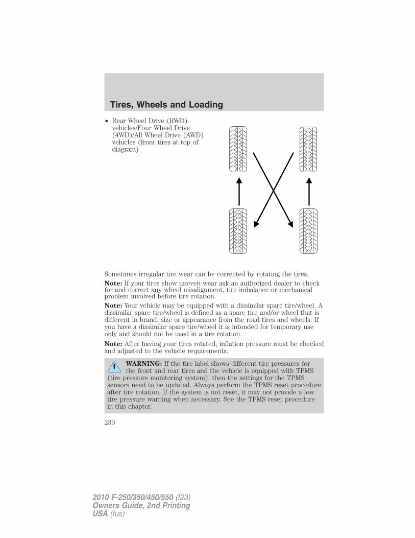
• Rear Wheel Drive (RWD)vehicles/Four Wheel Drive(4WD)/All Wheel Drive (AWD)vehicles (front tires at top ofdiagram)
Sometimes irregular tire wear can be corrected by rotating the tires.Note: If your tires show uneven wear ask an authorized dealer to checkfor and correct any wheel misalignment, tire imbalance or mechanicalproblem involved before tire rotation.Note: Your vehicle may be equipped with a dissimilar spare tire/wheel. Adissimilar spare tire/wheel is defined as a spare tire and/or wheel that isdifferent in brand, size or appearance from the road tires and wheels. Ifyou have a dissimilar spare tire/wheel it is intended for temporary useonly and should not be used in a tire rotation.
Note: After having your tires rotated, inflation pressure must be checkedand adjusted to the vehicle requirements.
WARNING: If the tire label shows different tire pressures forthe front and rear tires and the vehicle is equipped with TPMS
(tire pressure monitoring system), then the settings for the TPMSsensors need to be updated. Always perform the TPMS reset procedureafter tire rotation. If the system is not reset, it may not provide a lowtire pressure warning when necessary. See the TPMS reset procedurein this chapter.
Tires, Wheels and Loading
230
2010 F-250/350/450/550 (f23)Owners Guide, 2nd PrintingUSA (fus)
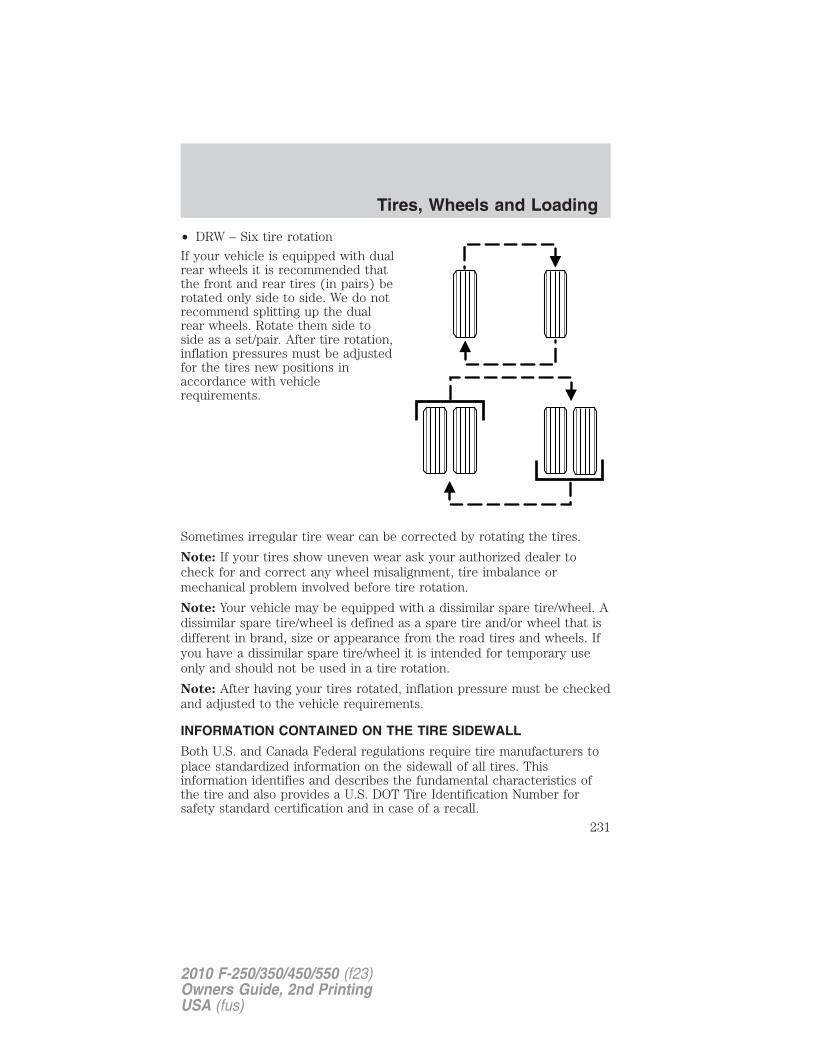
• DRW – Six tire rotation
If your vehicle is equipped with dualrear wheels it is recommended thatthe front and rear tires (in pairs) berotated only side to side. We do notrecommend splitting up the dualrear wheels. Rotate them side toside as a set/pair. After tire rotation,inflation pressures must be adjustedfor the tires new positions inaccordance with vehiclerequirements.
Sometimes irregular tire wear can be corrected by rotating the tires.
Note: If your tires show uneven wear ask your authorized dealer tocheck for and correct any wheel misalignment, tire imbalance ormechanical problem involved before tire rotation.
Note: Your vehicle may be equipped with a dissimilar spare tire/wheel. Adissimilar spare tire/wheel is defined as a spare tire and/or wheel that isdifferent in brand, size or appearance from the road tires and wheels. Ifyou have a dissimilar spare tire/wheel it is intended for temporary useonly and should not be used in a tire rotation.
Note: After having your tires rotated, inflation pressure must be checkedand adjusted to the vehicle requirements.
INFORMATION CONTAINED ON THE TIRE SIDEWALL
Both U.S. and Canada Federal regulations require tire manufacturers toplace standardized information on the sidewall of all tires. Thisinformation identifies and describes the fundamental characteristics ofthe tire and also provides a U.S. DOT Tire Identification Number forsafety standard certification and in case of a recall.
Tires, Wheels and Loading
231
2010 F-250/350/450/550 (f23)Owners Guide, 2nd PrintingUSA (fus)
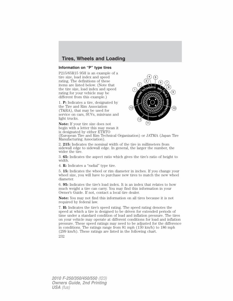
Information on “P” type tiresP215/65R15 95H is an example of atire size, load index and speedrating. The definitions of theseitems are listed below. (Note thatthe tire size, load index and speedrating for your vehicle may bedifferent from this example.)
1. P: Indicates a tire, designated bythe Tire and Rim Association(T&RA), that may be used forservice on cars, SUVs, minivans andlight trucks.
Note: If your tire size does notbegin with a letter this may mean itis designated by either ETRTO(European Tire and Rim Technical Organization) or JATMA (Japan TireManufacturing Association).2. 215: Indicates the nominal width of the tire in millimeters fromsidewall edge to sidewall edge. In general, the larger the number, thewider the tire.3. 65: Indicates the aspect ratio which gives the tire’s ratio of height towidth.4. R: Indicates a “radial” type tire.
5. 15: Indicates the wheel or rim diameter in inches. If you change yourwheel size, you will have to purchase new tires to match the new wheeldiameter.
6. 95: Indicates the tire’s load index. It is an index that relates to howmuch weight a tire can carry. You may find this information in yourOwner’s Guide. If not, contact a local tire dealer.
Note: You may not find this information on all tires because it is notrequired by federal law.
7. H: Indicates the tire’s speed rating. The speed rating denotes thespeed at which a tire is designed to be driven for extended periods oftime under a standard condition of load and inflation pressure. The tireson your vehicle may operate at different conditions for load and inflationpressure. These speed ratings may need to be adjusted for the differencein conditions. The ratings range from 81 mph (130 km/h) to 186 mph(299 km/h). These ratings are listed in the following chart.
Tires, Wheels and Loading
232
2010 F-250/350/450/550 (f23)Owners Guide, 2nd PrintingUSA (fus)
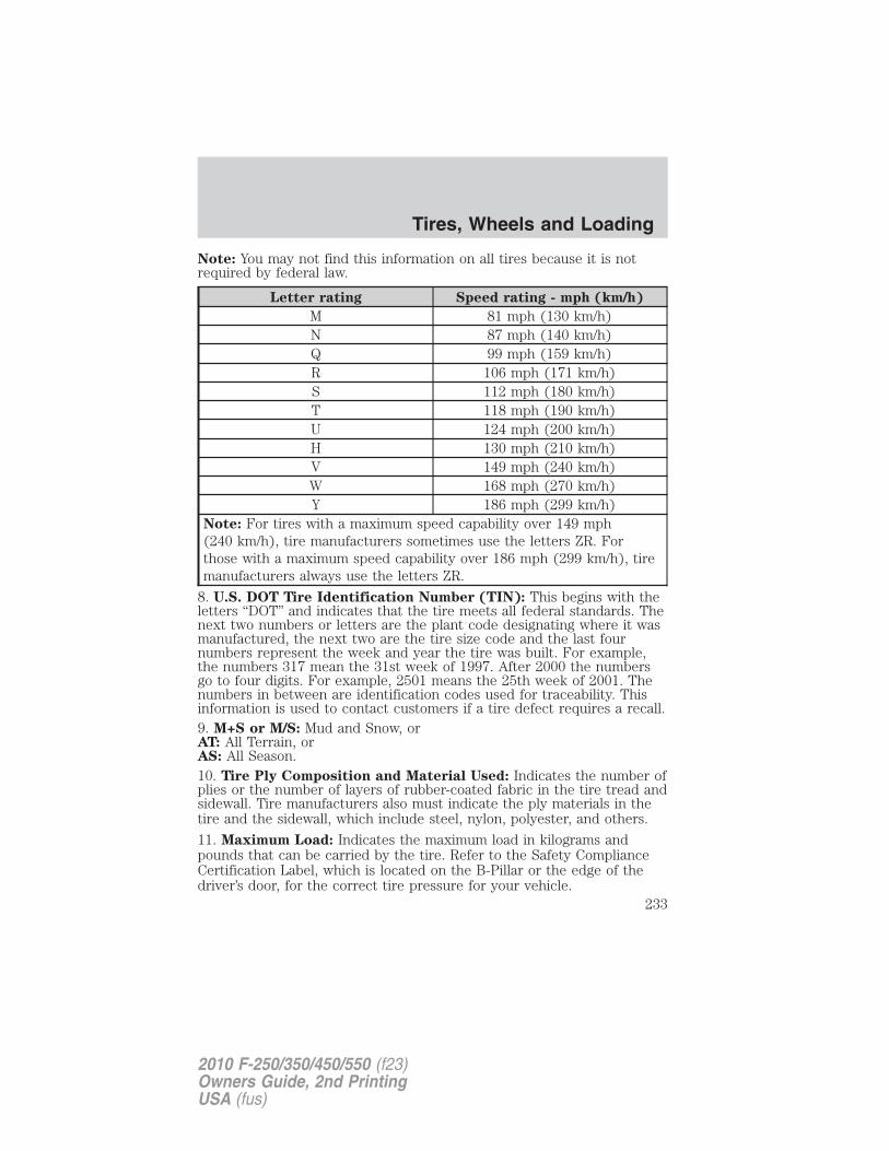
Note: You may not find this information on all tires because it is notrequired by federal law.
Letter rating Speed rating - mph (km/h)
M 81 mph (130 km/h)N 87 mph (140 km/h)Q 99 mph (159 km/h)R 106 mph (171 km/h)S 112 mph (180 km/h)T 118 mph (190 km/h)U 124 mph (200 km/h)H 130 mph (210 km/h)V 149 mph (240 km/h)W 168 mph (270 km/h)Y 186 mph (299 km/h)
Note: For tires with a maximum speed capability over 149 mph(240 km/h), tire manufacturers sometimes use the letters ZR. Forthose with a maximum speed capability over 186 mph (299 km/h), tiremanufacturers always use the letters ZR.
8. U.S. DOT Tire Identification Number (TIN): This begins with theletters “DOT” and indicates that the tire meets all federal standards. Thenext two numbers or letters are the plant code designating where it wasmanufactured, the next two are the tire size code and the last fournumbers represent the week and year the tire was built. For example,the numbers 317 mean the 31st week of 1997. After 2000 the numbersgo to four digits. For example, 2501 means the 25th week of 2001. Thenumbers in between are identification codes used for traceability. Thisinformation is used to contact customers if a tire defect requires a recall.9. M+S or M/S: Mud and Snow, orAT: All Terrain, orAS: All Season.10. Tire Ply Composition and Material Used: Indicates the number ofplies or the number of layers of rubber-coated fabric in the tire tread andsidewall. Tire manufacturers also must indicate the ply materials in thetire and the sidewall, which include steel, nylon, polyester, and others.
11. Maximum Load: Indicates the maximum load in kilograms andpounds that can be carried by the tire. Refer to the Safety ComplianceCertification Label, which is located on the B-Pillar or the edge of thedriver’s door, for the correct tire pressure for your vehicle.
Tires, Wheels and Loading
233
2010 F-250/350/450/550 (f23)Owners Guide, 2nd PrintingUSA (fus)
12. Treadwear, Traction and Temperature Grades
• Treadwear: The treadwear grade is a comparative rating based on thewear rate of the tire when tested under controlled conditions on aspecified government test course. For example, a tire graded 150would wear one and one-half (11⁄2) times as well on the governmentcourse as a tire graded 100.
• Traction: The traction grades, from highest to lowest are AA, A, B,and C. The grades represent the tire’s ability to stop on wet pavementas measured under controlled conditions on specified government testsurfaces of asphalt and concrete. A tire marked C may have poortraction performance.
• Temperature: The temperature grades are A (the highest), B and C,representing the tire’s resistance to the generation of heat and itsability to dissipate heat when tested under controlled conditions on aspecified indoor laboratory test wheel.
13. Maximum Permissible Inflation Pressure: Indicates the tiremanufacturers’ maximum permissible pressure and/or the pressure atwhich the maximum load can be carried by the tire. This pressure isnormally higher than the manufacturer’s recommended cold inflationpressure which can be found on the Safety Compliance CertificationLabel or Tire Label which is located on the B-Pillar or the edge of thedriver’s door. The cold inflation pressure should never be set lower thanthe recommended pressure on the vehicle label.
The tire suppliers may have additional markings, notes or warnings suchas standard load, radial tubeless, etc.
Tires, Wheels and Loading
234
2010 F-250/350/450/550 (f23)Owners Guide, 2nd PrintingUSA (fus)
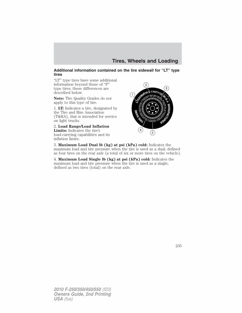
Additional information contained on the tire sidewall for “LT” typetires“LT” type tires have some additionalinformation beyond those of “P”type tires; these differences aredescribed below.
Note: Tire Quality Grades do notapply to this type of tire.
1. LT: Indicates a tire, designated bythe Tire and Rim Association(T&RA), that is intended for serviceon light trucks.
2. Load Range/Load InflationLimits: Indicates the tire’sload-carrying capabilities and itsinflation limits.
3. Maximum Load Dual lb (kg) at psi (kPa) cold: Indicates themaximum load and tire pressure when the tire is used as a dual; definedas four tires on the rear axle (a total of six or more tires on the vehicle).
4. Maximum Load Single lb (kg) at psi (kPa) cold: Indicates themaximum load and tire pressure when the tire is used as a single;defined as two tires (total) on the rear axle.
Tires, Wheels and Loading
235
2010 F-250/350/450/550 (f23)Owners Guide, 2nd PrintingUSA (fus)
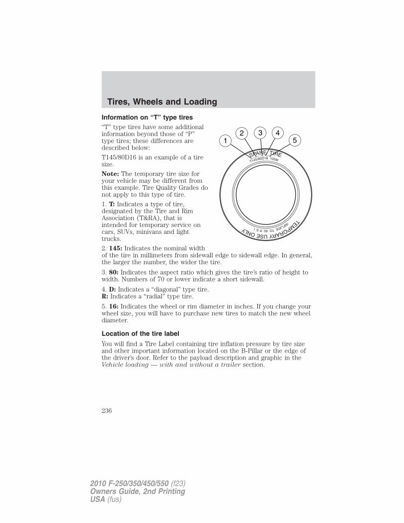
Information on “T” type tires“T” type tires have some additionalinformation beyond those of “P”type tires; these differences aredescribed below:
T145/80D16 is an example of a tiresize.
Note: The temporary tire size foryour vehicle may be different fromthis example. Tire Quality Grades donot apply to this type of tire.
1. T: Indicates a type of tire,designated by the Tire and RimAssociation (T&RA), that isintended for temporary service oncars, SUVs, minivans and lighttrucks.
2. 145: Indicates the nominal widthof the tire in millimeters from sidewall edge to sidewall edge. In general,the larger the number, the wider the tire.
3. 80: Indicates the aspect ratio which gives the tire’s ratio of height towidth. Numbers of 70 or lower indicate a short sidewall.
4. D: Indicates a “diagonal” type tire.R: Indicates a “radial” type tire.
5. 16: Indicates the wheel or rim diameter in inches. If you change yourwheel size, you will have to purchase new tires to match the new wheeldiameter.
Location of the tire label
You will find a Tire Label containing tire inflation pressure by tire sizeand other important information located on the B-Pillar or the edge ofthe driver’s door. Refer to the payload description and graphic in theVehicle loading — with and without a trailer section.
Tires, Wheels and Loading
236
2010 F-250/350/450/550 (f23)Owners Guide, 2nd PrintingUSA (fus)
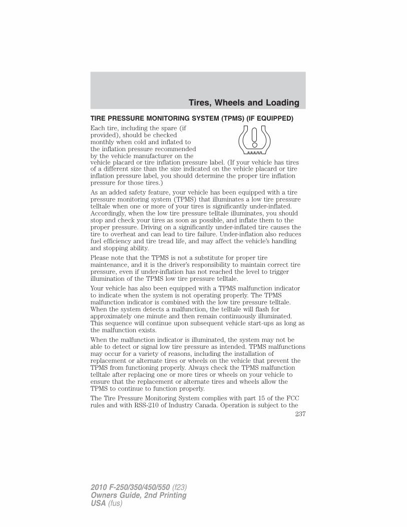
TIRE PRESSURE MONITORING SYSTEM (TPMS) (IF EQUIPPED)Each tire, including the spare (ifprovided), should be checkedmonthly when cold and inflated tothe inflation pressure recommendedby the vehicle manufacturer on thevehicle placard or tire inflation pressure label. (If your vehicle has tiresof a different size than the size indicated on the vehicle placard or tireinflation pressure label, you should determine the proper tire inflationpressure for those tires.)
As an added safety feature, your vehicle has been equipped with a tirepressure monitoring system (TPMS) that illuminates a low tire pressuretelltale when one or more of your tires is significantly under-inflated.Accordingly, when the low tire pressure telltale illuminates, you shouldstop and check your tires as soon as possible, and inflate them to theproper pressure. Driving on a significantly under-inflated tire causes thetire to overheat and can lead to tire failure. Under-inflation also reducesfuel efficiency and tire tread life, and may affect the vehicle’s handlingand stopping ability.
Please note that the TPMS is not a substitute for proper tiremaintenance, and it is the driver’s responsibility to maintain correct tirepressure, even if under-inflation has not reached the level to triggerillumination of the TPMS low tire pressure telltale.
Your vehicle has also been equipped with a TPMS malfunction indicatorto indicate when the system is not operating properly. The TPMSmalfunction indicator is combined with the low tire pressure telltale.When the system detects a malfunction, the telltale will flash forapproximately one minute and then remain continuously illuminated.This sequence will continue upon subsequent vehicle start-ups as long asthe malfunction exists.
When the malfunction indicator is illuminated, the system may not beable to detect or signal low tire pressure as intended. TPMS malfunctionsmay occur for a variety of reasons, including the installation ofreplacement or alternate tires or wheels on the vehicle that prevent theTPMS from functioning properly. Always check the TPMS malfunctiontelltale after replacing one or more tires or wheels on your vehicle toensure that the replacement or alternate tires and wheels allow theTPMS to continue to function properly.
The Tire Pressure Monitoring System complies with part 15 of the FCCrules and with RSS-210 of Industry Canada. Operation is subject to the
Tires, Wheels and Loading
237
2010 F-250/350/450/550 (f23)Owners Guide, 2nd PrintingUSA (fus)
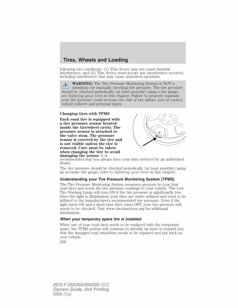
following two conditions: (1) This device may not cause harmfulinterference, and (2) This device must accept any interference received,including interference that may cause undesired operation.
WARNING: The Tire Pressure Monitoring System is NOT asubstitute for manually checking tire pressure. The tire pressure
should be checked periodically (at least monthly) using a tire gauge,see Inflating your tires in this chapter. Failure to properly maintainyour tire pressure could increase the risk of tire failure, loss of control,vehicle rollover and personal injury.
Changing tires with TPMS
Each road tire is equipped witha tire pressure sensor locatedinside the tire/wheel cavity. Thepressure sensor is attached tothe valve stem. The pressuresensor is covered by the tire andis not visible unless the tire isremoved. Care must be takenwhen changing the tire to avoiddamaging the sensor. It isrecommended that you always have your tires serviced by an authorizeddealer.The tire pressure should be checked periodically (at least monthly) usingan accurate tire gauge, refer to Inflating your tires in this chapter.
Understanding your Tire Pressure Monitoring System (TPMS)The Tire Pressure Monitoring System measures pressure in your fourroad tires and sends the tire pressure readings to your vehicle. The LowTire Warning Lamp will turn ON if the tire pressure is significantly low.Once the light is illuminated, your tires are under inflated and need to beinflated to the manufacturer’s recommended tire pressure. Even if thelight turns ON and a short time later turns OFF, your tire pressure stillneeds to be checked. Visit www.checkmytires.org for additionalinformation.
When your temporary spare tire is installedWhen one of your road tires needs to be replaced with the temporaryspare, the TPMS system will continue to identify an issue to remind youthat the damaged road wheel/tire needs to be repaired and put back onyour vehicle.
Tires, Wheels and Loading
238
2010 F-250/350/450/550 (f23)Owners Guide, 2nd PrintingUSA (fus)
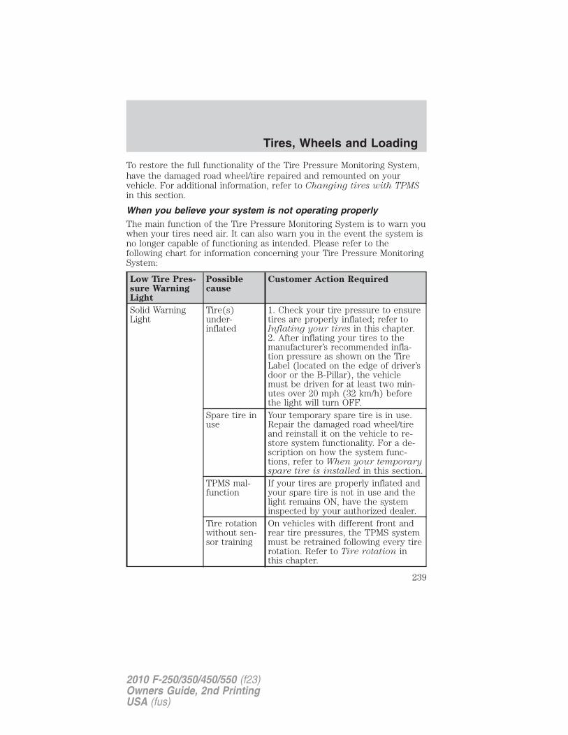
To restore the full functionality of the Tire Pressure Monitoring System,have the damaged road wheel/tire repaired and remounted on yourvehicle. For additional information, refer to Changing tires with TPMSin this section.
When you believe your system is not operating properlyThe main function of the Tire Pressure Monitoring System is to warn youwhen your tires need air. It can also warn you in the event the system isno longer capable of functioning as intended. Please refer to thefollowing chart for information concerning your Tire Pressure MonitoringSystem:
Low Tire Pres-sure WarningLight
Possiblecause
Customer Action Required
Solid WarningLight
Tire(s)under-inflated
1. Check your tire pressure to ensuretires are properly inflated; refer toInflating your tires in this chapter.2. After inflating your tires to themanufacturer’s recommended infla-tion pressure as shown on the TireLabel (located on the edge of driver’sdoor or the B-Pillar), the vehiclemust be driven for at least two min-utes over 20 mph (32 km/h) beforethe light will turn OFF.
Spare tire inuse
Your temporary spare tire is in use.Repair the damaged road wheel/tireand reinstall it on the vehicle to re-store system functionality. For a de-scription on how the system func-tions, refer to When your temporaryspare tire is installed in this section.
TPMS mal-function
If your tires are properly inflated andyour spare tire is not in use and thelight remains ON, have the systeminspected by your authorized dealer.
Tire rotationwithout sen-sor training
On vehicles with different front andrear tire pressures, the TPMS systemmust be retrained following every tirerotation. Refer to Tire rotation inthis chapter.
Tires, Wheels and Loading
239
2010 F-250/350/450/550 (f23)Owners Guide, 2nd PrintingUSA (fus)
Low Tire Pres-sure WarningLight
Possiblecause
Customer Action Required
Flashing WarningLight
Spare tire inuse
Your temporary spare tire is in use.Repair the damaged road wheel andre-mount it on the vehicle to restoresystem functionality. For a descrip-tion of how the system functions un-der these conditions, refer to Whenyour temporary spare tire is in-stalled in this section.
TPMS mal-function
If your tires are properly inflated andyour spare tire is not in use and theTPMS warning light still flashes, havethe system inspected by your autho-rized dealer.
When inflating your tires
When putting air into your tires (such as at a gas station or in yourgarage), the Tire Pressure Monitoring System may not respondimmediately to the air added to your tires.
It may take up to two minutes of driving over 20 mph (32 km/h) for thelight to turn OFF after you have filled your tires to the recommendedinflation pressure.
How temperature affects your tire pressureThe Tire Pressure Monitoring System (TPMS) monitors tire pressure ineach pneumatic tire. While driving in a normal manner, a typicalpassenger tire inflation pressure may increase approximately 2 to 4 psi(14 to 28 kPa) from a cold start situation. If the vehicle is stationaryover night with the outside temperature significantly lower than thedaytime temperature, the tire pressure may decrease approximately 3 psi(20.7 kPa) for a drop of 30°F (16.6°C) in ambient temperature. Thislower pressure value may be detected by the TPMS as being significantlylower than the recommended inflation pressure and activate the TPMSwarning for low tire pressure. If the low tire pressure warning light isON, visually check each tire to verify that no tire is flat. (If one or moretires are flat, repair as necessary.) Check air pressure in the road tires. Ifany tire is under-inflated, carefully drive the vehicle to the nearestlocation where air can be added to the tires. Inflate all the tires to therecommended inflation pressure.
Tires, Wheels and Loading
240
2010 F-250/350/450/550 (f23)Owners Guide, 2nd PrintingUSA (fus)
TPMS reset procedure
The TPMS reset procedure needs to be performed after each tire
rotation on vehicles that require different recommended tire
pressures in the front tires as compared to the rear tires.
WARNING: To determine the required pressure(s) for yourvehicle – refer to the Safety Compliance Certification Label or
Tire Label located on the B-Pillar or the edge of the driver’s door. SeeVehicle loading in this chapter for more information.
OverviewTo provide the vehicle’s load carrying capability, some vehicles requiredifferent recommended tire pressures in the front tires as compared tothe rear tires. The Tire Pressure Monitoring System (TPMS) equipped onthese vehicles is designed to illuminate the Low Tire Pressure Warningindicator at two different pressures; one for the front tires and one forthe rear tires.
Since tires need to be rotated to provide consistent performance andmaximum tire life, the Tire Pressure Monitoring System needs to knowwhen the tires are rotated to determine which set of tires are on thefront and which are on the rear. With this information, the system candetect and properly warn of low tire pressures.
TPMS reset tips:
• To reduce the chances of interference from another vehicle, the TPMSreset procedure should be performed at least 3 feet (1 meter) awayfrom another Ford Motor Company vehicle undergoing the TPMS resetprocedure at the same time.
• Do not wait more than two (2) minutes between resetting each tiresensor or the system will timeout and the entire procedure will haveto be repeated on all four wheels.
• A double horn chirp indicates the need to repeat the procedure.
Performing the TPMS reset procedureIt is recommended that you read the entire procedure before attempting.
1. Drive the vehicle above 20 mph (32 km/h) for at least 2 minutes andthen park in a safe location where you can easily get to all four tires andhave access to an air pump.
2. Place the ignition in the off position and keep the key in the ignition.
Tires, Wheels and Loading
241
2010 F-250/350/450/550 (f23)Owners Guide, 2nd PrintingUSA (fus)
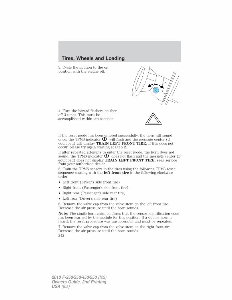
3. Cycle the ignition to the onposition with the engine off.
4. Turn the hazard flashers on thenoff 3 times. This must beaccomplished within ten seconds.
If the reset mode has been entered successfully, the horn will soundonce, the TPMS indicator will flash and the message center (ifequipped) will display TRAIN LEFT FRONT TIRE. If this does notoccur, please try again starting at Step 2.If after repeated attempts to enter the reset mode, the horn does notsound, the TPMS indicator does not flash and the message center (ifequipped) does not display TRAIN LEFT FRONT TIRE, seek servicefrom your authorized dealer.5. Train the TPMS sensors in the tires using the following TPMS resetsequence starting with the left front tire in the following clockwiseorder:
• Left front (Driver’s side front tire)
• Right front (Passenger’s side front tire)
• Right rear (Passenger’s side rear tire)
• Left rear (Driver’s side rear tire)
6. Remove the valve cap from the valve stem on the left front tire.Decrease the air pressure until the horn sounds.
Note: The single horn chirp confirms that the sensor identification codehas been learned by the module for this position. If a double horn isheard, the reset procedure was unsuccessful, and must be repeated.
7. Remove the valve cap from the valve stem on the right front tire.Decrease the air pressure until the horn sounds.
Tires, Wheels and Loading
242
2010 F-250/350/450/550 (f23)Owners Guide, 2nd PrintingUSA (fus)
8. Remove the valve cap from the valve stem on the right rear tire.Decrease the air pressure until the horn sounds.
9. Remove the valve cap from the valve stem on the left rear tire.Decrease the air pressure until the horn sounds.
Training is complete after the horn sounds for the last tire trained(driver’s side rear tire), the TPMS tell tale stops flashing, and themessage center (if equipped) displays:TRAINING COMPLETE.
10. Turn the ignition off. If two short horn beeps are heard, the resetprocedure was unsuccessful and must be repeated.
If after repeating the procedure and two short beeps are heard when theignition is turned to off, seek assistance from your authorized dealer.
11. Set all four tires to the recommended air pressure as indicated onthe Safety Compliance Certification Label or Tire Label located on theB-Pillar or the edge of the driver’s door. See Vehicle loading - with andwithout a trailer in this chapter for more information.
SNOW TIRES AND CHAINS
WARNING: Snow tires must be the same size, load index, speedrating as those originally provided by Ford. Use of any tire or
wheel not recommended by Ford can affect the safety andperformance of your vehicle, which could result in an increased risk ofloss of vehicle control, vehicle rollover, personal injury and death.Additionally, the use of non-recommended tires and wheels couldcause steering, suspension, axle or transfer case/power transfer unitfailure.
Note: Do not use snow chains on vehicles with 20 inch wheels and tires.
The tires on your vehicle have all weather treads to provide traction inrain and snow. However, in some climates, you may need to use snowtires and chains. If you need to use chains, it is recommended that steelwheels (of the same size and specifications) be used, as chains may chipaluminum wheels.
Tires, Wheels and Loading
243
2010 F-250/350/450/550 (f23)Owners Guide, 2nd PrintingUSA (fus)
Follow these guidelines when using snow tires and chains:
• Use only SAE Class S chains.
• Install chains securely, verifying that the chains do not touch anywiring, brake lines or fuel lines.
• Drive cautiously. If you hear the chains rub or bang against yourvehicle, stop and re-tighten the chains. If this does not work, removethe chains to prevent damage to your vehicle.
• If possible, avoid fully loading your vehicle.
• Remove the tire chains when they are no longer needed. Do not usetire chains on dry roads.
• The suspension insulation and bumpers will help prevent vehicledamage. Do not remove these components from your vehicle whenusing snow tires and chains.
VEHICLE LOADING – WITH AND WITHOUT A TRAILER
This section will guide you in the proper loading of your vehicle and/ortrailer, to keep your loaded vehicle weight within its design ratingcapability, with or without a trailer. Properly loading your vehicle willprovide maximum return of vehicle design performance. Before loadingyour vehicle, familiarize yourself with the following terms for determiningyour vehicle’s weight ratings, with or without a trailer, from the vehicle’sTire Label or Safety Compliance Certification Label:
Base Curb Weight – is the weight of the vehicle including a full tank offuel and all standard equipment. It does not include passengers, cargo, oroptional equipment.
Vehicle Curb Weight – is the weight of your new vehicle when youpicked it up from your authorized dealer plus any aftermarketequipment.
Tires, Wheels and Loading
244
2010 F-250/350/450/550 (f23)Owners Guide, 2nd PrintingUSA (fus)
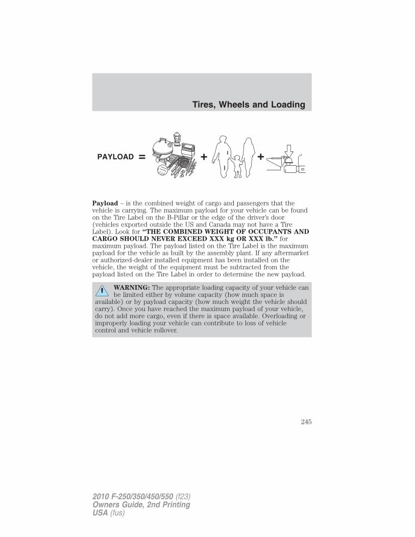
Payload – is the combined weight of cargo and passengers that thevehicle is carrying. The maximum payload for your vehicle can be foundon the Tire Label on the B-Pillar or the edge of the driver’s door(vehicles exported outside the US and Canada may not have a TireLabel). Look for “THE COMBINED WEIGHT OF OCCUPANTS ANDCARGO SHOULD NEVER EXCEED XXX kg OR XXX lb.” formaximum payload. The payload listed on the Tire Label is the maximumpayload for the vehicle as built by the assembly plant. If any aftermarketor authorized-dealer installed equipment has been installed on thevehicle, the weight of the equipment must be subtracted from thepayload listed on the Tire Label in order to determine the new payload.
WARNING: The appropriate loading capacity of your vehicle canbe limited either by volume capacity (how much space is
available) or by payload capacity (how much weight the vehicle shouldcarry). Once you have reached the maximum payload of your vehicle,do not add more cargo, even if there is space available. Overloading orimproperly loading your vehicle can contribute to loss of vehiclecontrol and vehicle rollover.
Tires, Wheels and Loading
245
2010 F-250/350/450/550 (f23)Owners Guide, 2nd PrintingUSA (fus)
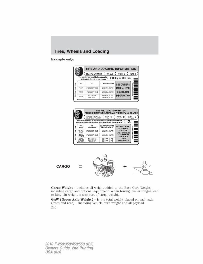
Example only:
Cargo Weight – includes all weight added to the Base Curb Weight,including cargo and optional equipment. When towing, trailer tongue loador king pin weight is also part of cargo weight.
GAW (Gross Axle Weight) – is the total weight placed on each axle(front and rear) – including vehicle curb weight and all payload.
Tires, Wheels and Loading
246
2010 F-250/350/450/550 (f23)Owners Guide, 2nd PrintingUSA (fus)
GAWR (Gross Axle Weight Rating) – is the maximum allowableweight that can be carried by a single axle (front or rear). Thesenumbers are shown on the Safety Compliance Certification Labellocated on the B-Pillar or the edge of the driver’s door. The totalload on each axle must never exceed its GAWR.
Note: For trailer towing information refer to Trailer towing found inthis chapter or the RV and Trailer Towing Guide provided by yourauthorized dealer.
GVW (Gross Vehicle Weight) – is the Vehicle Curb Weight + cargo +passengers.
GVWR (Gross Vehicle Weight Rating) – is the maximum allowableweight of the fully loaded vehicle (including all options, equipment,passengers and cargo). The GVWR is shown on the SafetyCompliance Certification Label located on the B-Pillar or theedge of the driver’s door. The GVW must never exceed the GVWR.
Tires, Wheels and Loading
247
2010 F-250/350/450/550 (f23)Owners Guide, 2nd PrintingUSA (fus)
• Example only:
WARNING: Exceeding the Safety Compliance Certification Labelvehicle weight rating limits could result in substandard vehicle
handling or performance, engine, transmission and/or structuraldamage, serious damage to the vehicle, loss of control and personalinjury.
Tires, Wheels and Loading
248
2010 F-250/350/450/550 (f23)Owners Guide, 2nd PrintingUSA (fus)
GCW (Gross Combined Weight) – is the weight of the loaded vehicle(GVW) plus the weight of the fully loaded trailer.GCWR (Gross Combined Weight Rating) – is the maximum allowableweight of the vehicle and the loaded trailer – including all cargo andpassengers – that the vehicle can handle without risking damage.(Important: The towing vehicle’s braking system is rated for operation atGVWR, not at GCWR.) Separate functional brakes should be used forsafe control of towed vehicles and for trailers where the GCW of thetowing vehicle plus the trailer exceed the GVWR of the towing vehicle.The GCW must never exceed the GCWR.
Maximum Loaded Trailer Weight – is the highest possible weight of afully loaded trailer the vehicle can tow. It assumes a vehicle with onlymandatory options, no cargo (internal or external), a tongue load of10–15% (conventional trailer) or king pin weight of 15–25% (fifth wheeltrailer), and driver only (150 lb. [68 kg]). Consult your authorizeddealer (or the RV and Trailer Towing Guide provided by yourauthorized dealer) for more detailed information.
Tongue Load or Fifth Wheel King Pin Weight – refers to the amountof the weight that a trailer pushes down on a trailer hitch.
Examples: For a 5,000 lb. (2,268 kg) conventional trailer, multiply 5,000by 0.10 and 0.15 to obtain a proper tongue load range of 500 to 750 lb.(227 to 340 kg). For an 11,500 lb. (5,216 kg) fifth wheel trailer, multiplyby 0.15 and 0.25 to obtain a proper king pin load range of 1,725 to2,875 lb. (782 to 1,304 kg)
WARNING: Do not exceed the GVWR or the GAWR specified onthe Safety Compliance Certification Label.
WARNING: Do not use replacement tires with lower loadcarrying capacities than the original tires because they may
lower the vehicle’s GVWR and GAWR limitations. Replacement tireswith a higher limit than the original tires do not increase the GVWRand GAWR limitations.
Tires, Wheels and Loading
249
2010 F-250/350/450/550 (f23)Owners Guide, 2nd PrintingUSA (fus)
WARNING: Exceeding any vehicle weight rating limitation couldresult in serious damage to the vehicle and/or personal injury.
Steps for determining the correct load limit:
1. Locate the statement “The combined weight of occupants and cargoshould never exceed XXX kg or XXX lb.” on your vehicle’s placard.
2. Determine the combined weight of the driver and passengers that willbe riding in your vehicle.
3. Subtract the combined weight of the driver and passengers from XXXkg or XXX lb.
4. The resulting figure equals the available amount of cargo and luggageload capacity. For example, if the “XXX” amount equals 1,400 lb. andthere will be five 150 lb. passengers in your vehicle, the amount ofavailable cargo and luggage load capacity is 650 lb. (1400-750 (5 x 150) =650 lb.). In metric units (635-340 (5 x 68) = 295 kg.)
5. Determine the combined weight of luggage and cargo being loaded onthe vehicle. That weight may not safely exceed the available cargo andluggage load capacity calculated in Step 4.
6. If your vehicle will be towing a trailer, load from your trailer will betransferred to your vehicle. Consult this manual to determine how thisreduces the available cargo and luggage load capacity of your vehicle.
The following gives you a few examples on how to calculate the availableamount of cargo and luggage load capacity:
• Another example for your vehicle with 1,400 lb. (635 kg) of cargo andluggage capacity. You decide to go golfing. Is there enough loadcapacity to carry you, 4 of your friends and all the golf bags? You andfour friends average 220 lb. (99 kg) each and the golf bags weighapproximately 30 lb. (13.5 kg) each. The calculation would be: 1400 -(5 x 220) - (5 x 30) = 1400 - 1100 - 150 = 150 lb. Yes, you haveenough load capacity in your vehicle to transport four friends andyour golf bags. In metric units, the calculation would be: 635 kg - (5 x99 kg) - (5 x 13.5 kg) = 635 - 495 - 67.5 = 72.5 kg.
• A final example for your vehicle with 1,400 lb. (635 kg) of cargo andluggage capacity. You and one of your friends decide to pick upcement from the local home improvement store to finish that patioyou have been planning for the past 2 years. Measuring the inside ofthe vehicle with the rear seat folded down, you have room for12-100 lb. (45 kg) bags of cement. Do you have enough load capacity
Tires, Wheels and Loading
250
2010 F-250/350/450/550 (f23)Owners Guide, 2nd PrintingUSA (fus)
to transport the cement to your home? If you and your friend eachweigh 220 lb. (99 kg), the calculation would be: 1400 - (2 x 220) - (12x 100) = 1400 - 440 - 1200 = - 240 lb. No, you do not have enoughcargo capacity to carry that much weight. In metric units, thecalculation would be: 635 kg - (2 x 99 kg) - (12 x 45 kg) = 635 - 198 -540 = -103 kg. You will need to reduce the load weight by at least240 lb. (104 kg). If you remove 3-100 lb. (45 kg) cement bags, thenthe load calculation would be:1400 - (2 x 220) - (9 x 100) = 1400 - 440 - 900 = 60 lb. Now you havethe load capacity to transport the cement and your friend home. Inmetric units, the calculation would be: 635 kg - (2 x 99 kg) - (9 x45 kg) = 635 - 198 - 405 = 32 kg.
The above calculations also assume that the loads are positioned in yourvehicle in a manner that does not overload the Front or the Rear GrossAxle Weight Rating specified for your vehicle on the Safety ComplianceCertification Label found on the edge of the driver’s door.
Special loading instructions for owners of pickup trucks andutility-type vehicles
WARNING: For important information regarding safe operationof this type of vehicle, see the Preparing to drive your vehicle
section in the Driving chapter of this Owner’s Guide.
WARNING: Loaded vehicles may handle differently thanunloaded vehicles. Extra precautions, such as slower speeds and
increased stopping distance, should be taken when driving a heavilyloaded vehicle.
Your vehicle can haul more cargo and people than most passenger cars.Depending upon the type and placement of the load, hauling cargo andpeople may raise the center of gravity of the vehicle.
TRAILER TOWINGNote: The trailer towing charts in this section apply to vehicles equippedwith gasoline engines; for vehicles equipped with diesel engines, refer toyour Power Stroke Direct Injection Turbo Diesel Owner’s GuideSupplement.
Your vehicle may tow a Conventional/Class IV trailer or fifth wheel trailerprovided the maximum trailer weight is less than or equal to themaximum trailer weight listed for your engine and rear axle ratio on thefollowing charts.
Tires, Wheels and Loading
251
2010 F-250/350/450/550 (f23)Owners Guide, 2nd PrintingUSA (fus)
To calculate your maximum trailer weight:
For pickup trucks: Take curb weight, hitch hardware and the driver’sweight, then subtract them from the GCWR listed for your vehicle series,engine, transmission and drive axle ratio (refer to the chart/table in thefollowing text). This calculation will give you the maximum trailerweight possible for your vehicle.
For chassis cabs and pickup trucks with aftermarket equipment:Weigh your vehicle at a certified scale and subtract this actual curbweight, hitch hardware, and the driver’s weight from the GCWR listed foryour vehicle series, engine, transmission and drive axle ratio (refer tothe chart/table in the following text). This calculation will give you themaximum trailer weight possible for your vehicle.
The weight of all additional cargo and passengers must be subtractedfrom the maximum trailer weight calculated above.
Further trailer/hitch restrictions and limitations exist depending on thetype of trailer and hitch used. These additional maximum trailer weightand tongue load limitations are listed in the chart/table that follows thelisting of GCWRs.
Towing a trailer places an additional load on your vehicle’s engine,transmission, axle, brakes, tires and suspension. Inspect thesecomponents carefully prior to and after any towing operation. Refer toTransmission fluid temperature gauge in the Instrument Clusterchapter for the transmission fluid temperature information.
Note: Do not exceed the GCWR listed for your vehicle on the followingchart/table, or the GVWR, GAWR or tire ratings specified on the TireLabel or Safety Compliance Certification Label.
WARNING: Towing trailers beyond the maximum recommendedtrailer weight which exceeds the limit of the vehicle’s GCWR,
GVWR, GAWR or tire ratings could result in engine damage,transmission damage, structural damage, loss of vehicle control, vehiclerollover and personal injury.
Tires, Wheels and Loading
252
2010 F-250/350/450/550 (f23)Owners Guide, 2nd PrintingUSA (fus)
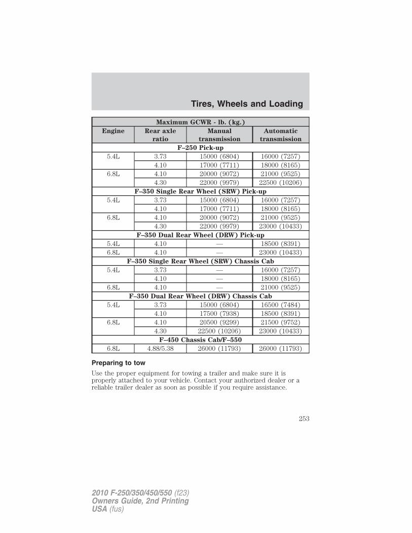
Maximum GCWR - lb. (kg.)
Engine Rear axle
ratio
Manual
transmission
Automatic
transmission
F–250 Pick-up
5.4L 3.73 15000 (6804) 16000 (7257)4.10 17000 (7711) 18000 (8165)
6.8L 4.10 20000 (9072) 21000 (9525)4.30 22000 (9979) 22500 (10206)
F–350 Single Rear Wheel (SRW) Pick-up
5.4L 3.73 15000 (6804) 16000 (7257)4.10 17000 (7711) 18000 (8165)
6.8L 4.10 20000 (9072) 21000 (9525)4.30 22000 (9979) 23000 (10433)
F–350 Dual Rear Wheel (DRW) Pick-up
5.4L 4.10 — 18500 (8391)6.8L 4.10 — 23000 (10433)
F–350 Single Rear Wheel (SRW) Chassis Cab
5.4L 3.73 — 16000 (7257)4.10 — 18000 (8165)
6.8L 4.10 — 21000 (9525)F–350 Dual Rear Wheel (DRW) Chassis Cab
5.4L 3.73 15000 (6804) 16500 (7484)4.10 17500 (7938) 18500 (8391)
6.8L 4.10 20500 (9299) 21500 (9752)4.30 22500 (10206) 23000 (10433)
F–450 Chassis Cab/F–550
6.8L 4.88/5.38 26000 (11793) 26000 (11793)
Preparing to tow
Use the proper equipment for towing a trailer and make sure it isproperly attached to your vehicle. Contact your authorized dealer or areliable trailer dealer as soon as possible if you require assistance.
Tires, Wheels and Loading
253
2010 F-250/350/450/550 (f23)Owners Guide, 2nd PrintingUSA (fus)
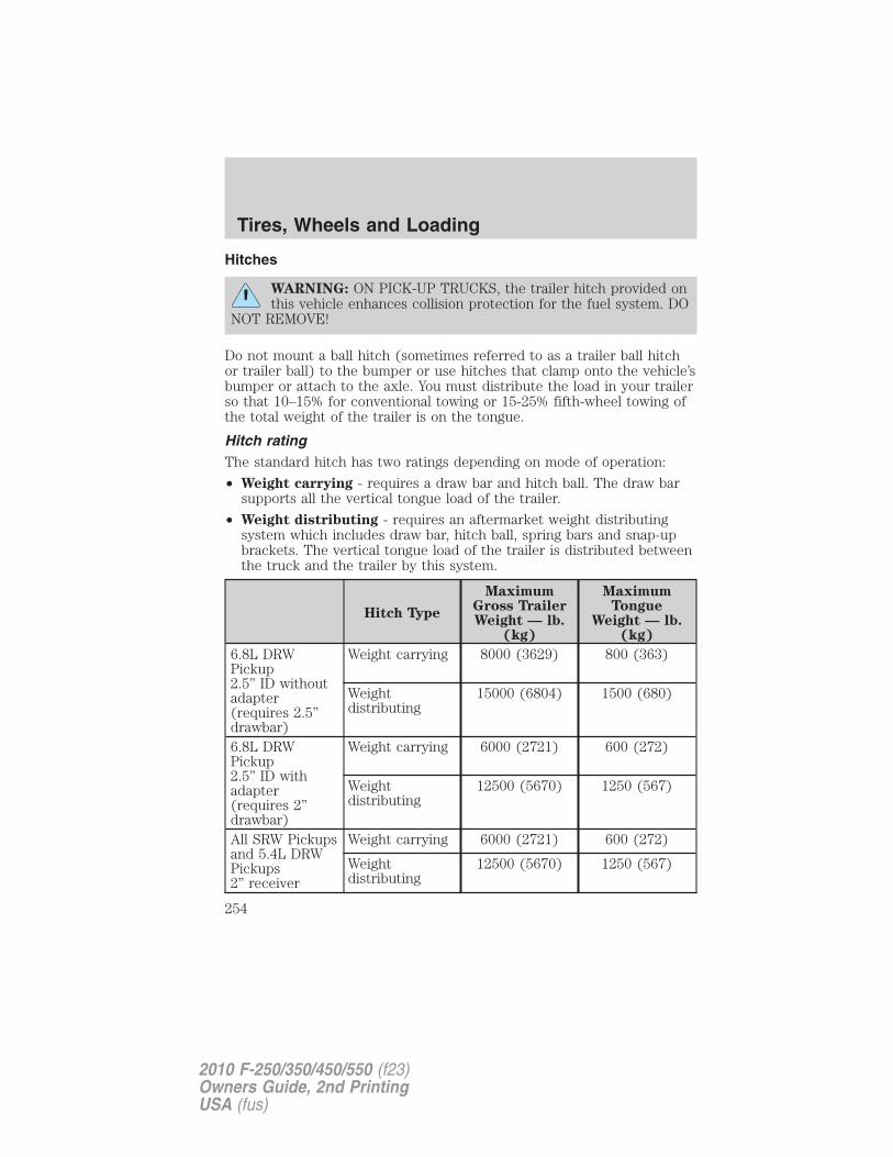
Hitches
WARNING: ON PICK-UP TRUCKS, the trailer hitch provided onthis vehicle enhances collision protection for the fuel system. DO
NOT REMOVE!
Do not mount a ball hitch (sometimes referred to as a trailer ball hitchor trailer ball) to the bumper or use hitches that clamp onto the vehicle’sbumper or attach to the axle. You must distribute the load in your trailerso that 10–15% for conventional towing or 15-25% fifth-wheel towing ofthe total weight of the trailer is on the tongue.
Hitch ratingThe standard hitch has two ratings depending on mode of operation:
• Weight carrying - requires a draw bar and hitch ball. The draw barsupports all the vertical tongue load of the trailer.
• Weight distributing - requires an aftermarket weight distributingsystem which includes draw bar, hitch ball, spring bars and snap-upbrackets. The vertical tongue load of the trailer is distributed betweenthe truck and the trailer by this system.
Hitch Type
MaximumGross TrailerWeight — lb.
(kg)
MaximumTongue
Weight — lb.(kg)
6.8L DRWPickup2.5” ID withoutadapter(requires 2.5”drawbar)
Weight carrying 8000 (3629) 800 (363)
Weightdistributing
15000 (6804) 1500 (680)
6.8L DRWPickup2.5” ID withadapter(requires 2”drawbar)
Weight carrying 6000 (2721) 600 (272)
Weightdistributing
12500 (5670) 1250 (567)
All SRW Pickupsand 5.4L DRWPickups2” receiver
Weight carrying 6000 (2721) 600 (272)
Weightdistributing
12500 (5670) 1250 (567)
Tires, Wheels and Loading
254
2010 F-250/350/450/550 (f23)Owners Guide, 2nd PrintingUSA (fus)
WARNING: Towing trailers beyond the maximum tongue weightexceeds the limit of the towing system and could result in
vehicle structural damage, loss of vehicle control and personal injury.
Weight-distributing hitch
When hooking-up a trailer using a load-equalizing hitch, always use thefollowing procedure:
1. Park the unloaded vehicle on a level surface. With the ignition on andall doors closed, allow the vehicle to stand for several minutes so that itcan level.
2. Measure the height of a reference point on the front and rear bumpersat the center of the vehicle.
3. Attach the trailer to the vehicle and adjust the hitch equalizers so thatthe front bumper height is within 1⁄2” (13 mm) of the reference point.After proper adjustment, the rear bumper should be no higher than inStep 2.
WARNING: Do not adjust a weight-distributing hitch to anyposition where the rear bumper of the vehicle is higher than it
was before attaching the trailer. Doing so will defeat the function ofthe weight-distributing hitch, which may cause unpredictable handling,and could result in serious personal injury.
Safety chains
Always connect the trailer’s safety chains to the frame or hook retainersof the vehicle hitch. To connect the trailer’s safety chains, cross thechains under the trailer tongue and allow slack for turning corners.
If you use a rental trailer, follow the instructions that the rental agencygives to you.
Do not attach safety chains to the bumper.
Trailer brakesElectric brakes and manual, automatic or surge-type trailer brakes aresafe if installed properly and adjusted to the manufacturer’sspecifications. The trailer brakes must meet local and Federalregulations.
Tires, Wheels and Loading
255
2010 F-250/350/450/550 (f23)Owners Guide, 2nd PrintingUSA (fus)
WARNING: If you own a trailer with a hydraulic brake system,do not connect the trailer’s hydraulic brake system directly to
your vehicle’s brake system. The vehicle’s brake system is onlydesigned to carry the appropriate amount of brake fluid for the vehiclealone. Connecting a hydraulic trailer braking system could adverselyaffect your vehicle’s braking performance.
The braking system of the tow vehicle is rated for operation at theGVWR not GCWR.
Integrated trailer brake controller (if equipped)Your vehicle may be equipped with a fully integrated electronic trailerbrake controller (TBC). When used properly, the TBC helps ensuresmooth and effective trailer braking by powering the trailer’s electricbrakes with a proportional output based on the towing vehicle’s brakepressure.
WARNING: The Ford TBC has only been verified to becompatible with trailers having electric-actuated drum brakes
(one to four axles) and not hydraulic surge or electric-over-hydraulictypes. It is the responsibility of the customer to ensure that the trailerbrakes are adjusted appropriately, functioning normally and all electricconnections are properly made.
The TBC user interface consists ofthe following:
1. +/- (GAIN adjustmentbuttons): Pressing these buttonswill adjust the TBC’s power outputto the trailer brakes (in0.5 increments). The GAIN settingcan be increased to a maximum of10.0 or decreased to a minimum of 0 (no trailer braking). Pressing andholding a button will raise or lower the setting continuously. The gainsetting will display in the message center as follows: TBC GAIN = XX.X.
The trailer brake controller (TBC) is designed to display three items ofinformation in the instrument cluster message center. These are: gainsetting, output bar graph, and trailer connectivity status. They willappear as follows in the message center.
• TBC GAIN = XX.X NO TRAILER: The instrument cluster messagecenter will display the current gain setting during a given ignition
Tires, Wheels and Loading
256
2010 F-250/350/450/550 (f23)Owners Guide, 2nd PrintingUSA (fus)
cycle and when adjusting the gain. This message is also displayedduring manual activation without a trailer connected or when gainadjustments are made with no trailer connected.
• TBC GAIN = XX.X OUTPUT = //////: When the vehicle’s brake pedalis pushed, or when the manual control is activated, bar indicators willilluminate in the instrument cluster message center to indicate theamount of power going to the trailer brakes relative to the brake pedalor manual control input. One bar indicates the least amount of outputwith six bars indicating maximum output.
• TRAILER CONNECTED: This message is displayed when a correcttrailer wiring connection (a trailer with electric trailer brakes) hasbeen sensed during a given ignition cycle.
• TRAILER DISCONNECTED: This message is displayed andaccompanied by a single chime, when a trailer connection wasdetermined and then a disconnection, either intentionally orunintentionally, has been sensed during a given ignition cycle. It is alsodisplayed if a truck or trailer wiring fault occurs causing the trailer toappear disconnected. This message is also displayed during manualactivation without a trailer connected.
2. Manual control lever: Slide the control lever to the left to activatepower to the trailer’s electric brakes independent of the tow vehicle’sbrakes (see the following Procedure for adjusting GAIN section forinstructions on proper use of this feature). If the manual control isactivated while the brake is also applied, the greater of the two inputsdetermines the power sent to the trailer brakes.
• Stop Lamps: Activating the TBC manual control lever will illuminateboth the trailer brake lamps and the tow vehicle brake lamps exceptthe center high-mount stop lamp (presuming proper trailer electricalconnection). Pressing the vehicle brake pedal will also illuminate bothtrailer and vehicle brake lamps.
Procedure for adjusting GAIN:
The GAIN setting is used to set the TBC for the specific towingcondition and should be changed as towing conditions change. Changesto towing conditions include trailer load, vehicle load, road conditionsand weather.
The GAIN should be set to provide the maximum trailer brakingassistance while ensuring the trailer wheels do not lock when braking.Locked trailer wheels may lead to trailer instability.
Note: This should only be performed in a traffic free environment atspeeds of approximately 20–25 mph (30–40 km/h).
Tires, Wheels and Loading
257
2010 F-250/350/450/550 (f23)Owners Guide, 2nd PrintingUSA (fus)
1. Make sure the trailer brakes are in good working condition,functioning normally, and properly adjusted. See your trailer dealer ifnecessary.2. Hook up the trailer and make the electrical connections according tothe trailer manufacturer’s instructions.3. When a trailer with electric brakes is plugged in, the TRAILERCONNECTED message will display in the instrument cluster messagecenter.4. Use the GAIN adjustment (+/-) buttons to increase or decrease theGAIN setting to the desired starting point. A GAIN setting of 6.0 is agood starting point for heavier loads.5. In a traffic-free environment, tow the trailer on a dry, level surface ata speed of 20–25 mph (30–40 km/h) and squeeze the manual controllever completely.6. If the trailer wheels lock-up (indicated by squealing tires), reduce theGAIN setting; if the trailer wheels turn freely, increase the GAIN setting.Repeat Steps 5 and 6 until the GAIN setting is at a point just belowtrailer wheel lock-up. If towing a heavier trailer, trailer wheel lockup maynot be attainable even with the maximum GAIN setting of 10.Explanation of instrument cluster warning messages:
The TBC interacts with the instrument cluster message center to displaythe following messages:TRAILER BRAKE MODULE FAULT: This message is displayed andaccompanied by a single chime, in response to faults sensed by the TBC.In the event this message is seen, please contact your authorized dealeras soon as possible for diagnosis and repair. The TBC may still function,but performance may be degraded.WIRING FAULT ON TRAILER: This message is displayed when aShort circuit on the electric brake output wire has occurred. If theWIRING FAULT ON TRAILER message is displayed and accompaniedby a single chime, with no trailer connected, the problem is with thevehicle wiring from the TBC to the 7–pin connector in the bumper. If themessage is only displayed with a trailer connected, the problem is relatedto the trailer wiring; consult your trailer dealer for assistance. This canbe a short to ground (i.e., chaffed wire) or a short to voltage (i.e., pulledpin on trailer emergency break-away battery) or trailer brakes drawingtoo much current.
Note: Your TBC can be diagnosed by your authorized dealer todetermine exactly which trailer fault has occurred; however, if the faultis with the trailer this diagnosis is not covered under your Fordwarranty.
Tires, Wheels and Loading
258
2010 F-250/350/450/550 (f23)Owners Guide, 2nd PrintingUSA (fus)
Points to Remember:
• Remember to adjust gain setting before using the TBC for the firsttime.
• Readjust GAIN setting on the TBC (according to procedure above)whenever road, weather and trailer or vehicle loading conditionschange from those that existed when the gain was initially set.
• The sliding lever on the TBC should be used only for manualactivation of trailer brakes to assist with proper adjustment of theGAIN. Misuse, such as application during trailer sway, could causeinstability of trailer and/or tow vehicle.
• Avoid towing in adverse weather conditions. The TBC does notprovide anti-lock control of the trailer wheels. Trailer wheels canlock-up on slippery surfaces, resulting in reduced stability of trailerand tow vehicle.
• The TBC interacts with the brake system of the vehicle, includingABS, in order to reduce the likelihood of trailer wheel lockup.Therefore, if these systems are not functioning properly the TBC maynot function at full performance.
• When the vehicle is turned off, the TBC Output is disabled and thedisplay is shut down. Reactivation of the ignition from OFF to ON willawaken the TBC module.
• The TBC is only a factory or dealer installed item. Ford is notresponsible for warranty or performance of the TBC due to misuse orcustomer installation.
• Do not attempt removal of the TBC without consulting theWorkshop Manual. Damage to the unit may result.
Trailer lampsTrailer lamps are required on most towed vehicles. Make sure all runninglights, brake lights, turn signals and hazard lights are working. Contactyour authorized dealer or trailer rental agency for proper instructionsand equipment for hooking-up trailer lamps.
Driving while you towWhen towing a trailer:
• Do not drive faster than 70 mph (113 km/h) during the first 500 miles(800 km) of trailer towing and don’t make full-throttle starts.
• Consult your local motor vehicle speed regulations for towing a trailer.
Tires, Wheels and Loading
259
2010 F-250/350/450/550 (f23)Owners Guide, 2nd PrintingUSA (fus)
• Turn off the speed control. The speed control may shut offautomatically when you are towing on long, steep grades.
• To eliminate excessive transmission shifting, activate the Tow/Haulfeature. This will also assist in transmission cooling. For additionalinformation, refer to Automatic transmission operation in theDriving chapter.
• Anticipate stops and brake gradually.
• Do not exceed the GCWR rating or transmission damage may occur.
• Your vehicle may be equipped with a temporary or conventional sparetire. If the spare tire is different in size (diameter and/or width), treadtype (All-Season or All-Terrain) or is from a different manufacturerother than the road tires on your vehicle, your spare tire is considered“temporary”. Consult information on the spare Tire Label or SafetyCompliance Certification Label for limitations when using.
Servicing after towingIf you tow a trailer for long distances, your vehicle will require morefrequent service intervals. Refer to your scheduled maintenanceinformation for more information.
Trailer towing safety tips
General• Ensure that the trailer, safety chains and 7–pin electrical connectors
are securely fastened.
• Make sure the truck receiver, draw bar, and coupler are properlyconnected and adjusted.
• Check rear view and side mirrors for proper visibility especially whentowing trailer wider than the truck.
• When turning make wide turns to allow trailer tires to properly clearany obstacles.
• When towing, operate the vehicle at lower speeds than you wouldwhen not towing a trailer. The likelihood of trailer sway is greater athigher speeds.
• Be prepared for trailer sway due to buffeting when larger vehiclespass in either direction.
• If you will be towing a trailer frequently in hot weather, hillyconditions, at GCWR, or any combination of these factors, considerrefilling your rear axle with synthetic gear lubricant if not already so
Tires, Wheels and Loading
260
2010 F-250/350/450/550 (f23)Owners Guide, 2nd PrintingUSA (fus)
equipped. Refer to Maintenance product specifications andcapacities in the Maintenance and Specifications chapter for theproper axle lubricant. Remember that regardless of the rear axlelubricant used, do not tow a trailer for the first 500 miles (800 km) ofa new vehicle, and that the first 500 miles (800 km) of towing be doneat no faster than 70 mph (113 km/h) with no full-throttle starts.
Loading• Trailer loads should be evenly distributed front to back and left to
right.
• The load distribution within the trailer should be such that 10–15% ofthe trailer weight is on the hitch (15–25% for fifth-wheel or goosenecktowing).
• Never exceed truck, trailer, receiver, ball, tongue, tire or couplerloading recommendations.
• Keep the center-of-gravity low for best handling.
Braking• Anticipate the need to stop; allow much more distance and time to
stop than normal.
• Do not apply the trailer brakes for extended periods of time as theycan overheat and lose effectiveness.
• The trailer brakes must be inspected and serviced at intervalsspecified by the manufacturer. This includes the shoes, drum andtrailer brake magnets.
• Electric brakes also require periodic adjustment to keep the shoesproperly spaced. If the brakes get hot when driving or if they will nothold, chances are that they need adjustment.
Backing-up• Practice backing-up, particularly if you are a novice. Turn the steering
wheel to the right to move the trailer’s rear end to the right.
• Sharp steering movements may cause the trailer to jackknife or go outof control.
Tires• Select tires that meet the trailer loading requirements.
• All trailer tires should be of the same size, and construction.
• Always check tow vehicle and trailer tire pressure before towing.
Tires, Wheels and Loading
261
2010 F-250/350/450/550 (f23)Owners Guide, 2nd PrintingUSA (fus)
Launching or retrieving a boatDisconnect the wiring to the trailer before backing the trailerinto the water. Reconnect the wiring to the trailer after thetrailer is removed from the water.
When backing down a ramp during boat launching or retrieval:
• do not allow the static water level to rise above the bottom edge ofthe rear bumper.
• do not allow waves to break higher than 6 inches (15 cm) above thebottom edge of the rear bumper.
Exceeding these limits may allow water to enter vehicle components:
• causing internal damage to the components.
• affecting driveability, emissions and reliability.
Replace the rear axle lubricant any time the axle has been submerged inwater. Rear axle lubricant quantities are not to be checked or changedunless a leak is suspected or repair required.
RECREATIONAL TOWINGFollow these guidelines if you have a need for recreational (RV) towing.An example of recreational towing would be towing your vehicle behinda motorhome. These guidelines are designed to ensure that yourtransmission is not damaged.
Note: Put your climate control system in recirculated air mode toprevent exhaust fumes from entering the vehicle. Refer to the ClimateControls chapter for more information.
Tires, Wheels and Loading
262
2010 F-250/350/450/550 (f23)Owners Guide, 2nd PrintingUSA (fus)
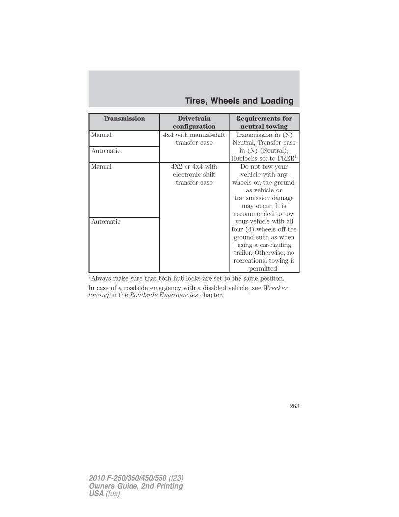
Transmission Drivetrain
configuration
Requirements for
neutral towing
Manual 4x4 with manual-shifttransfer case
Transmission in (N)Neutral; Transfer case
in (N) (Neutral);Hublocks set to FREE1
Automatic
Manual 4X2 or 4x4 withelectronic-shifttransfer case
Do not tow yourvehicle with any
wheels on the ground,as vehicle or
transmission damagemay occur. It is
recommended to towyour vehicle with all
four (4) wheels off theground such as when
using a car-haulingtrailer. Otherwise, norecreational towing is
permitted.
Automatic
1Always make sure that both hub locks are set to the same position.
In case of a roadside emergency with a disabled vehicle, see Wreckertowing in the Roadside Emergencies chapter.
Tires, Wheels and Loading
263
2010 F-250/350/450/550 (f23)Owners Guide, 2nd PrintingUSA (fus)
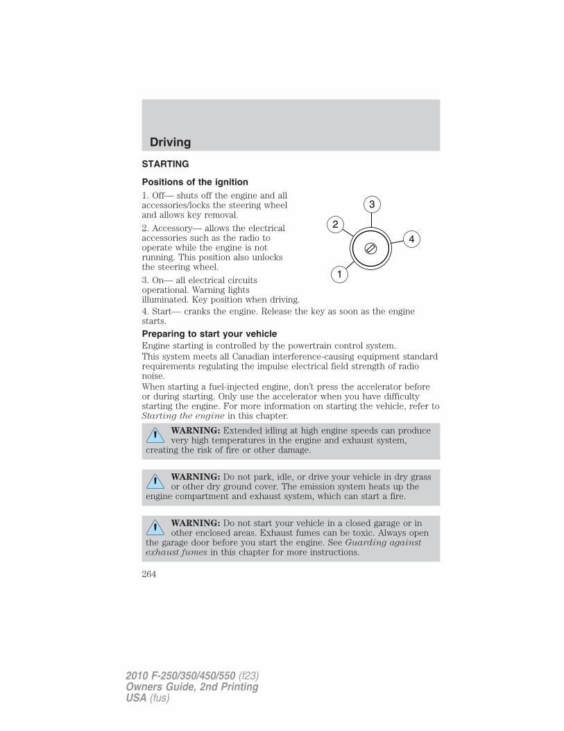
STARTING
Positions of the ignition1. Off— shuts off the engine and allaccessories/locks the steering wheeland allows key removal.
2. Accessory— allows the electricalaccessories such as the radio tooperate while the engine is notrunning. This position also unlocksthe steering wheel.
3. On— all electrical circuitsoperational. Warning lightsilluminated. Key position when driving.4. Start— cranks the engine. Release the key as soon as the enginestarts.
Preparing to start your vehicleEngine starting is controlled by the powertrain control system.This system meets all Canadian interference-causing equipment standardrequirements regulating the impulse electrical field strength of radionoise.When starting a fuel-injected engine, don’t press the accelerator beforeor during starting. Only use the accelerator when you have difficultystarting the engine. For more information on starting the vehicle, refer toStarting the engine in this chapter.
WARNING: Extended idling at high engine speeds can producevery high temperatures in the engine and exhaust system,
creating the risk of fire or other damage.
WARNING: Do not park, idle, or drive your vehicle in dry grassor other dry ground cover. The emission system heats up the
engine compartment and exhaust system, which can start a fire.
WARNING: Do not start your vehicle in a closed garage or inother enclosed areas. Exhaust fumes can be toxic. Always open
the garage door before you start the engine. See Guarding againstexhaust fumes in this chapter for more instructions.
Driving
264
2010 F-250/350/450/550 (f23)Owners Guide, 2nd PrintingUSA (fus)
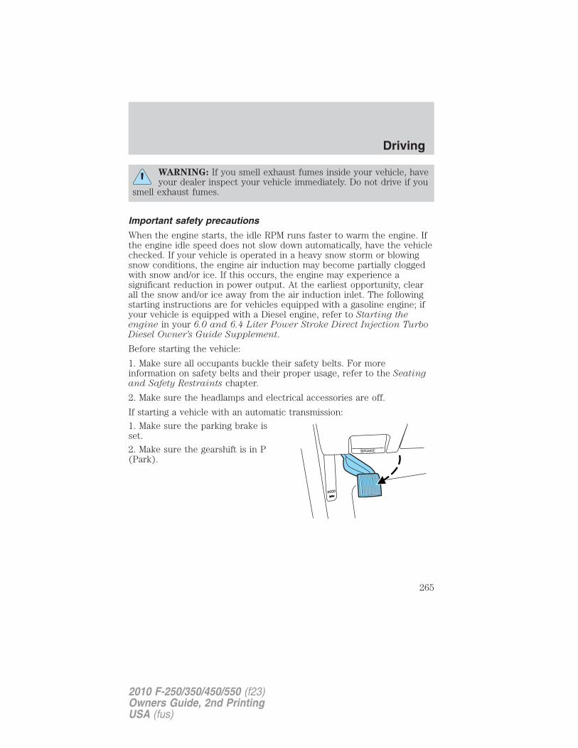
WARNING: If you smell exhaust fumes inside your vehicle, haveyour dealer inspect your vehicle immediately. Do not drive if you
smell exhaust fumes.
Important safety precautions
When the engine starts, the idle RPM runs faster to warm the engine. Ifthe engine idle speed does not slow down automatically, have the vehiclechecked. If your vehicle is operated in a heavy snow storm or blowingsnow conditions, the engine air induction may become partially cloggedwith snow and/or ice. If this occurs, the engine may experience asignificant reduction in power output. At the earliest opportunity, clearall the snow and/or ice away from the air induction inlet. The followingstarting instructions are for vehicles equipped with a gasoline engine; ifyour vehicle is equipped with a Diesel engine, refer to Starting theengine in your 6.0 and 6.4 Liter Power Stroke Direct Injection TurboDiesel Owner’s Guide Supplement.
Before starting the vehicle:
1. Make sure all occupants buckle their safety belts. For moreinformation on safety belts and their proper usage, refer to the Seatingand Safety Restraints chapter.
2. Make sure the headlamps and electrical accessories are off.
If starting a vehicle with an automatic transmission:
1. Make sure the parking brake isset.
2. Make sure the gearshift is in P(Park).
Driving
265
2010 F-250/350/450/550 (f23)Owners Guide, 2nd PrintingUSA (fus)
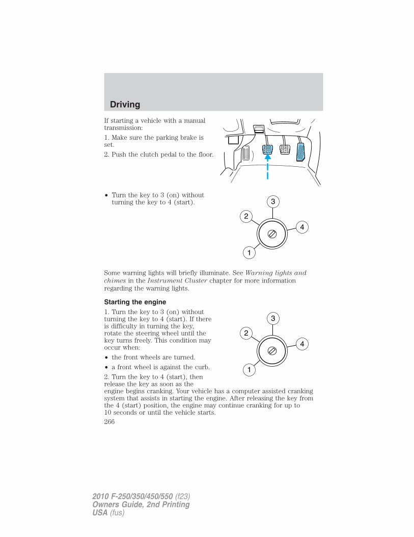
If starting a vehicle with a manualtransmission:
1. Make sure the parking brake isset.
2. Push the clutch pedal to the floor.
• Turn the key to 3 (on) withoutturning the key to 4 (start).
Some warning lights will briefly illuminate. See Warning lights and
chimes in the Instrument Cluster chapter for more informationregarding the warning lights.
Starting the engine1. Turn the key to 3 (on) withoutturning the key to 4 (start). If thereis difficulty in turning the key,rotate the steering wheel until thekey turns freely. This condition mayoccur when:
• the front wheels are turned.
• a front wheel is against the curb.
2. Turn the key to 4 (start), thenrelease the key as soon as theengine begins cranking. Your vehicle has a computer assisted crankingsystem that assists in starting the engine. After releasing the key fromthe 4 (start) position, the engine may continue cranking for up to10 seconds or until the vehicle starts.
Driving
266
2010 F-250/350/450/550 (f23)Owners Guide, 2nd PrintingUSA (fus)
Note: Cranking may be stopped at any time by turning the key to the offposition.3. After idling for a few seconds, release the parking brake, apply thebrake, shift into gear and drive.Note: If the engine does not start on the first try, turn the key to the offposition, wait 10 seconds and try Step 2 again. If the engine still fails tostart, press the accelerator to the floor and try Step 2 again, keeping theaccelerator on the floor until the engine begins to accelerate abovecranking speeds; this will allow the engine to crank with the fuel shut offin case the engine is flooded with fuel.
Guarding against exhaust fumesCarbon monoxide is present in exhaust fumes. Take precautions to avoidits dangerous effects.
WARNING: If you smell exhaust fumes inside your vehicle, haveyour dealer inspect your vehicle immediately. Do not drive if you
smell exhaust fumes.
Important ventilating informationIf the engine is idling while the vehicle is stopped for a long period oftime, open the windows at least 1 inch (2.5 cm) or adjust the heating orair conditioning to bring in fresh air.
ENGINE BLOCK HEATERAn engine block heater warms the engine coolant which aids in startingand allows the heater/defroster system to respond quickly. If your vehicleis equipped with this system, your equipment includes a heater elementwhich is installed in your engine block and a wire harness which allowsthe user to connect the system to a grounded 120 volt A/C electricalsource. The block heater system is most effective when outdoortemperatures reach below 0°F (-18°C).
WARNING: Failure to follow engine block heater instructionscould result in property damage or physical harm.
WARNING: To reduce the risk of electrical shock, do not useyour heater with ungrounded electrical systems or two-pronged
(cheater) adapters.
Driving
267
2010 F-250/350/450/550 (f23)Owners Guide, 2nd PrintingUSA (fus)
Prior to using the engine block heater, follow these recommendations forproper and safe operation:
• For your safety, use an outdoor extension cord that is productcertified by Underwriter’s laboratory (UL) or Canadian StandardsAssociation (CSA). Use only an extension cord that can be usedoutdoors, in cold temperatures, and is clearly marked �Suitable for Usewith Outdoor Appliances.� Never use an indoor extension cordoutdoors; it could result in an electric shock or fire hazard.
• Use a 16 gauge outdoor extension cord, minimum.
• Use as short an extension cord as possible.
• Do not use multiple extension cords. Instead, use one extension cordwhich is long enough to reach from the engine block heater cord tothe outlet without stretching.
• Make certain that the extension cord is in excellent condition (notpatched or spliced). Store your extension cord indoors attemperatures above 32°F (0°C). Outdoor conditions can deteriorateextension cords over a period of time.
• To reduce the risk of electrical shock, do not use your heater withungrounded electrical systems or two pronged (cheater) adapters.Also ensure that the block heater, especially the cord, is in goodcondition before use.
• Make sure that when in operation, the extension cord plug /engineblock heater cord plug connection is free and clear of water in orderto prevent possible shock or fire.
• Be sure that areas where the vehicle is parked are clean and clear ofall combustibles such as petroleum products, dust, rags, paper andsimilar items.
• Be sure that the engine block heater, heater cord and extension cordare solidly connected. A poor connection can cause the cord tobecome very hot and may result in an electrical shock or fire. Be sureto check for heat anywhere in the electrical hookup once the systemhas been operating for approximately a half hour.
• Finally, have the engine block heater system checked during your falltune-up to be sure it’s in good working order.
Driving
268
2010 F-250/350/450/550 (f23)Owners Guide, 2nd PrintingUSA (fus)
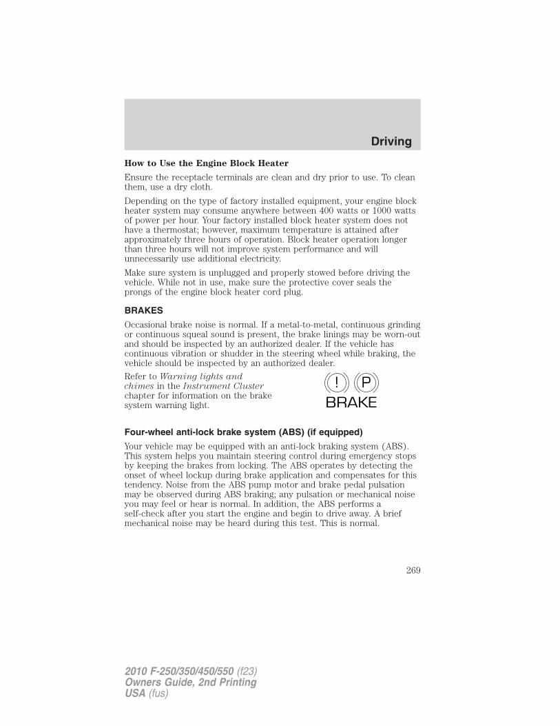
How to Use the Engine Block Heater
Ensure the receptacle terminals are clean and dry prior to use. To cleanthem, use a dry cloth.
Depending on the type of factory installed equipment, your engine blockheater system may consume anywhere between 400 watts or 1000 wattsof power per hour. Your factory installed block heater system does nothave a thermostat; however, maximum temperature is attained afterapproximately three hours of operation. Block heater operation longerthan three hours will not improve system performance and willunnecessarily use additional electricity.
Make sure system is unplugged and properly stowed before driving thevehicle. While not in use, make sure the protective cover seals theprongs of the engine block heater cord plug.
BRAKES
Occasional brake noise is normal. If a metal-to-metal, continuous grindingor continuous squeal sound is present, the brake linings may be worn-outand should be inspected by an authorized dealer. If the vehicle hascontinuous vibration or shudder in the steering wheel while braking, thevehicle should be inspected by an authorized dealer.
Refer to Warning lights andchimes in the Instrument Clusterchapter for information on the brakesystem warning light.
Four-wheel anti-lock brake system (ABS) (if equipped)
Your vehicle may be equipped with an anti-lock braking system (ABS).This system helps you maintain steering control during emergency stopsby keeping the brakes from locking. The ABS operates by detecting theonset of wheel lockup during brake application and compensates for thistendency. Noise from the ABS pump motor and brake pedal pulsationmay be observed during ABS braking; any pulsation or mechanical noiseyou may feel or hear is normal. In addition, the ABS performs aself-check after you start the engine and begin to drive away. A briefmechanical noise may be heard during this test. This is normal.
P!BRAKE
Driving
269
2010 F-250/350/450/550 (f23)Owners Guide, 2nd PrintingUSA (fus)
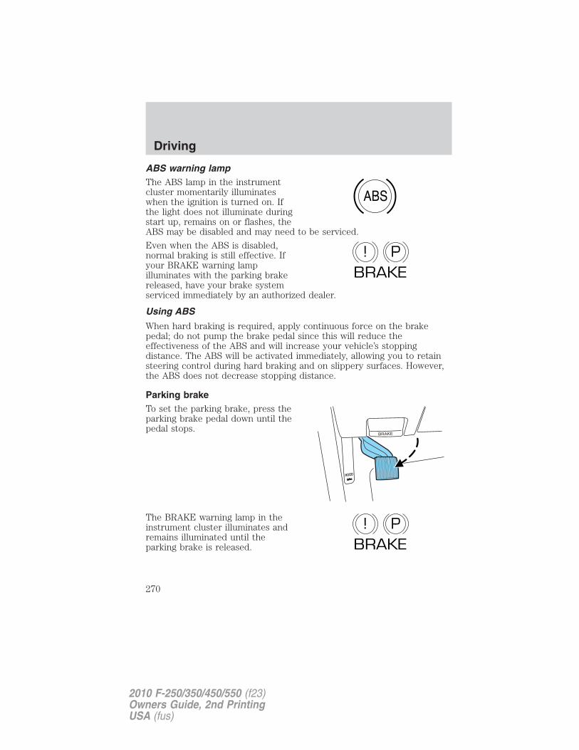
ABS warning lampThe ABS lamp in the instrumentcluster momentarily illuminateswhen the ignition is turned on. Ifthe light does not illuminate duringstart up, remains on or flashes, theABS may be disabled and may need to be serviced.
Even when the ABS is disabled,normal braking is still effective. Ifyour BRAKE warning lampilluminates with the parking brakereleased, have your brake systemserviced immediately by an authorized dealer.
Using ABS
When hard braking is required, apply continuous force on the brakepedal; do not pump the brake pedal since this will reduce theeffectiveness of the ABS and will increase your vehicle’s stoppingdistance. The ABS will be activated immediately, allowing you to retainsteering control during hard braking and on slippery surfaces. However,the ABS does not decrease stopping distance.
Parking brakeTo set the parking brake, press theparking brake pedal down until thepedal stops.
The BRAKE warning lamp in theinstrument cluster illuminates andremains illuminated until theparking brake is released.
ABS
P!BRAKE
P!BRAKE
Driving
270
2010 F-250/350/450/550 (f23)Owners Guide, 2nd PrintingUSA (fus)
Pull the release lever to release theparking brake. To prevent the pedalfrom releasing too quickly, placeyour left foot on the service brakepedal, then slowly pull the releaselever until the pedal slowly releases.Make sure that the pedal is fullyreleased. You may want to pull therelease lever again to make sure theparking brake is fully released.
WARNING: Always set the parking brake fully and make surethat the gearshift is securely latched in P (Park) (automatic
transmission) or in 1 (First) (manual transmission).
Note: If your vehicle is equipped with a manual transmission, the enginemay be required to run while power accessories operate and the parkingbrake is set. It is recommended that wheel chocks be used during thisoperation.If you’re parking your vehicle on a grade or with a trailer, press and holdthe brake pedal down, then set the parking brake. There may be a littlevehicle movement as the parking brake sets to hold the vehicle’s weight.This is normal and should be no reason for concern. If needed, press andhold the service brake pedal down, then try reapplying the parkingbrake. Chock the wheels if required. If the parking brake cannot hold theweight of the vehicle, the parking brake may need to be serviced or thevehicle may be overloaded.
TRACTION CONTROL (IF EQUIPPED)This system helps you maintain the stability and steerability of yourvehicle, especially on slippery road surfaces such as snow- or ice-coveredroads and gravel roads. The system will allow your vehicle to makebetter use of available traction in these conditions.
During traction control operation,the traction control light willilluminate and the engine will not“rev-up” when you press further onthe accelerator. This is normalsystem behavior and should be noreason for concern. Also, if traction control is on when the vehicle is putinto four-wheel drive mode (if equipped), the traction control system will
Driving
271
2010 F-250/350/450/550 (f23)Owners Guide, 2nd PrintingUSA (fus)
be automatically disabled. Traction control operation will resume whenthe vehicle is placed back into two-wheel drive mode.
WARNING: Aggressive driving in any road conditions can causeyou to lose control of your vehicle increasing the risk of severe
personal injury or property damage. The occurrence of a tractioncontrol event is an indication that at least some of the tires haveexceeded their ability to grip the road; this may lead to an increasedrisk of loss of vehicle control, vehicle rollover, personal injury anddeath. If you experience a severe road event, SLOW DOWN.
The traction control switch, locatedon the instrument panel to the leftof the climate control system, hasan indicator light that illuminateswhen the system is off. The tractioncontrol system will automaticallyturn on every time the ignition isturned off and on. The tractioncontrol system should normally be left on.If you should become stuck in snow or ice or on a very slippery roadsurface, try switching the traction control system off. This may allowexcess wheel spin to “dig” the vehicle out and enable a successful“rocking” maneuver.If a system fault is detected, the traction control active light willilluminate, the traction control button will not turn the system on or offand your vehicle should be serviced by an authorized dealer.
STEERINGTo help prevent damage to the power steering system:• Never hold the steering wheel at its furthest turning points (until it
stops) for more than three to five seconds when the engine is running.• Do not operate the vehicle with a low power steering pump fluid level
(below the MIN mark on the reservoir).• Some noise is normal during operation. If excessive, check for low
power steering pump fluid level before seeking service by your dealer.• Heavy or uneven efforts may be caused by low power steering fluid.
Check for low power steering pump fluid level before seeking serviceby your dealer.
• Do not fill the power steering pump reservoir above the MAX mark onthe reservoir, as this may result in leaks from the reservoir.
Driving
272
2010 F-250/350/450/550 (f23)Owners Guide, 2nd PrintingUSA (fus)
If the power steering system breaks down (or if the engine is turnedoff), you can steer the vehicle manually, but it takes more effort.If the steering wanders or pulls, check for:• an improperly inflated tire• uneven tire wear• loose or worn suspension components• loose or worn steering components• improper steering alignmentIf any steering components are serviced or replaced, install newfasteners (many are coated with thread adhesive or have prevailingtorque features which may not be re-used). Never re-use a bolt or nut.Torque fasteners to specifications in Workshop Manual.A high crown in the road or high crosswinds may also make the steeringseem to wander/pull.LIMITED-SLIP AXLE (IF EQUIPPED)This axle provides added traction on slippery surfaces, particularly whenone wheel is on a poor traction surface. Under normal conditions, theLimited-slip axle functions like a standard rear axle. The axle mayexhibit a slight noise or vibration in tight turns with low vehicle speed.This is normal behavior and indicates the axle is working.PREPARING TO DRIVE
WARNING: Utility vehicles have a significantly higher rolloverrate than other types of vehicles.
WARNING: In a rollover crash, an unbelted person issignificantly more likely to die than a person wearing a seat belt.
Utility vehicles and trucks have larger tires and increased groundclearance, giving the vehicle a higher center of gravity than a passengercar.
WARNING: Vehicles with a higher center of gravity such asutility vehicles and trucks handle differently than vehicles with a
lower center of gravity. Utility vehicles and trucks are not designed forcornering at speeds as high as passenger cars any more than low-slungsports cars are designed to perform satisfactorily under off-roadconditions. Avoid sharp turns, excessive speed or abrupt maneuvers inthese vehicles. Failure to drive cautiously could result in an increasedrisk of loss of vehicle control, vehicle rollover, personal injury anddeath.
Driving
273
2010 F-250/350/450/550 (f23)Owners Guide, 2nd PrintingUSA (fus)
WARNING: Loaded vehicles, with a higher center of gravity,may handle differently than unloaded vehicles. Do not overload
your vehicle and use extra precautions, such as driving at slowerspeeds, avoiding abrupt steering changes and allowing for increasedstopping distance, when driving a heavily loaded vehicle. Over-loadingor loading the vehicle improperly can deteriorate handling capabilityand contribute to loss of vehicle control and vehicle rollover.
BRAKE-SHIFT INTERLOCKThis vehicle is equipped with a brake-shift interlock feature that preventsthe gearshift lever from being moved from P (Park) when the ignition isin the 3 (on) position and the brake pedal is not pressed.
If you cannot move the gearshift lever out of P (Park) with ignition inthe on position and the brake pedal pressed, it is possible that a fuse hasblown or the vehicle’s brakelamps are not operating properly. Refer toFuses and relays in the Roadside Emergencies chapter.
If the fuse is not blown and the brakelamps are working properly, thefollowing procedure will allow you to move the gearshift lever from P(Park):
1. Apply the parking brake. Turn theignition key to 1 (off), then removethe key. Locate the access coverplate for the brake-shift interlockoverride. It is located on top of thesteering column shroud.
2. Apply the brake. Use a tool (or asmall screwdriver) to pry out theaccess cover. Insert the tool into theaccess hole and slide the whiteoverride button towards the left.Move the gear shift lever into N(Neutral) while holding the whiteoverride disc towards the left.
3. Start the vehicle.
Driving
274
2010 F-250/350/450/550 (f23)Owners Guide, 2nd PrintingUSA (fus)
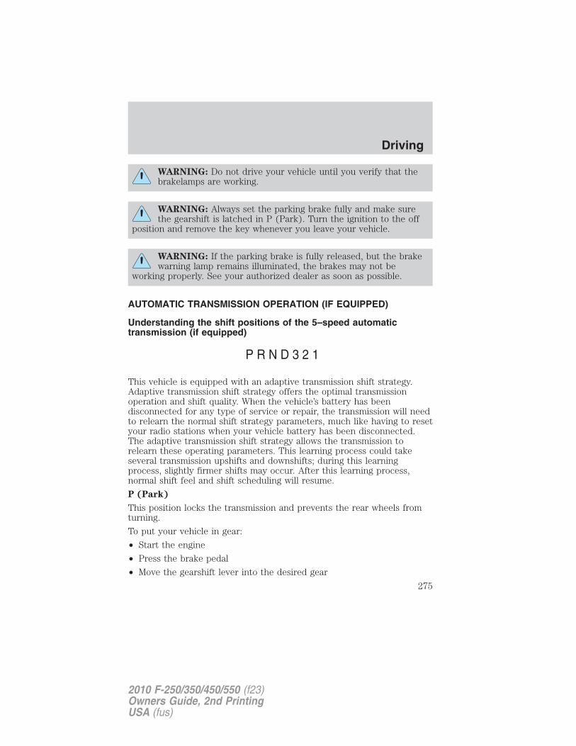
WARNING: Do not drive your vehicle until you verify that thebrakelamps are working.
WARNING: Always set the parking brake fully and make surethe gearshift is latched in P (Park). Turn the ignition to the off
position and remove the key whenever you leave your vehicle.
WARNING: If the parking brake is fully released, but the brakewarning lamp remains illuminated, the brakes may not be
working properly. See your authorized dealer as soon as possible.
AUTOMATIC TRANSMISSION OPERATION (IF EQUIPPED)
Understanding the shift positions of the 5–speed automatictransmission (if equipped)
This vehicle is equipped with an adaptive transmission shift strategy.Adaptive transmission shift strategy offers the optimal transmissionoperation and shift quality. When the vehicle’s battery has beendisconnected for any type of service or repair, the transmission will needto relearn the normal shift strategy parameters, much like having to resetyour radio stations when your vehicle battery has been disconnected.The adaptive transmission shift strategy allows the transmission torelearn these operating parameters. This learning process could takeseveral transmission upshifts and downshifts; during this learningprocess, slightly firmer shifts may occur. After this learning process,normal shift feel and shift scheduling will resume.
P (Park)
This position locks the transmission and prevents the rear wheels fromturning.
To put your vehicle in gear:
• Start the engine
• Press the brake pedal
• Move the gearshift lever into the desired gear
Driving
275
2010 F-250/350/450/550 (f23)Owners Guide, 2nd PrintingUSA (fus)
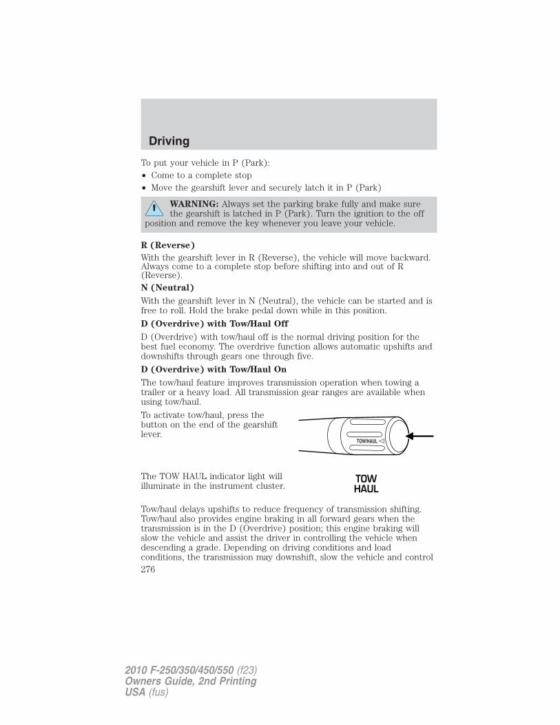
To put your vehicle in P (Park):• Come to a complete stop• Move the gearshift lever and securely latch it in P (Park)
WARNING: Always set the parking brake fully and make surethe gearshift is latched in P (Park). Turn the ignition to the off
position and remove the key whenever you leave your vehicle.
R (Reverse)
With the gearshift lever in R (Reverse), the vehicle will move backward.Always come to a complete stop before shifting into and out of R(Reverse).N (Neutral)
With the gearshift lever in N (Neutral), the vehicle can be started and isfree to roll. Hold the brake pedal down while in this position.
D (Overdrive) with Tow/Haul Off
D (Overdrive) with tow/haul off is the normal driving position for thebest fuel economy. The overdrive function allows automatic upshifts anddownshifts through gears one through five.
D (Overdrive) with Tow/Haul On
The tow/haul feature improves transmission operation when towing atrailer or a heavy load. All transmission gear ranges are available whenusing tow/haul.
To activate tow/haul, press thebutton on the end of the gearshiftlever.
The TOW HAUL indicator light willilluminate in the instrument cluster.
Tow/haul delays upshifts to reduce frequency of transmission shifting.Tow/haul also provides engine braking in all forward gears when thetransmission is in the D (Overdrive) position; this engine braking willslow the vehicle and assist the driver in controlling the vehicle whendescending a grade. Depending on driving conditions and loadconditions, the transmission may downshift, slow the vehicle and control
Driving
276
2010 F-250/350/450/550 (f23)Owners Guide, 2nd PrintingUSA (fus)
the vehicle speed when descending a hill, without the accelerator pedalbeing pressed. The amount of downshift braking provided will vary basedupon the amount the brake pedal is depressed.To deactivate the tow/haul feature and return to normal driving mode,press the button on the end of the gearshift lever. The TOW HAUL lightwill no longer be illuminated.When you shut-off and restart the engine, the transmission willautomatically return to normal D (Overdrive) mode (Tow/Haul OFF).
WARNING: Do not use the tow/haul feature when driving in icyor slippery conditions as the increased engine braking can cause
the rear wheels to slide and the vehicle to swing around with thepossible loss of vehicle control.
3 (Third)
Transmission starts and operates in third gear only.Used for improved traction on slippery roads. Selecting 3 (Third)provides engine braking.2 (Second)
Use 2 (Second) to start-up on slippery roads or to provide additionalengine braking on downgrades.1 (First)
• Provides maximum engine braking.• Allows upshifts by moving gearshift lever.• The transmission will not downshift into 1 (First) at high speeds; it
will downshift to a lower gear and then shift into 1 (First) when thevehicle reaches slower speeds.
Forced downshifts
• Allowed in D (Overdrive) or D (Drive).
• Press the accelerator to the floor.
• Allows transmission to select an appropriate gear.
If your vehicle gets stuck in mud or snowIf your vehicle gets stuck in mud or snow, it may be rocked out byshifting between forward and reverse gears, stopping between shifts in asteady pattern. Press lightly on the accelerator in each gear.
Do not rock the vehicle if the engine is not at normal operatingtemperature or damage to the transmission may occur.
Driving
277
2010 F-250/350/450/550 (f23)Owners Guide, 2nd PrintingUSA (fus)
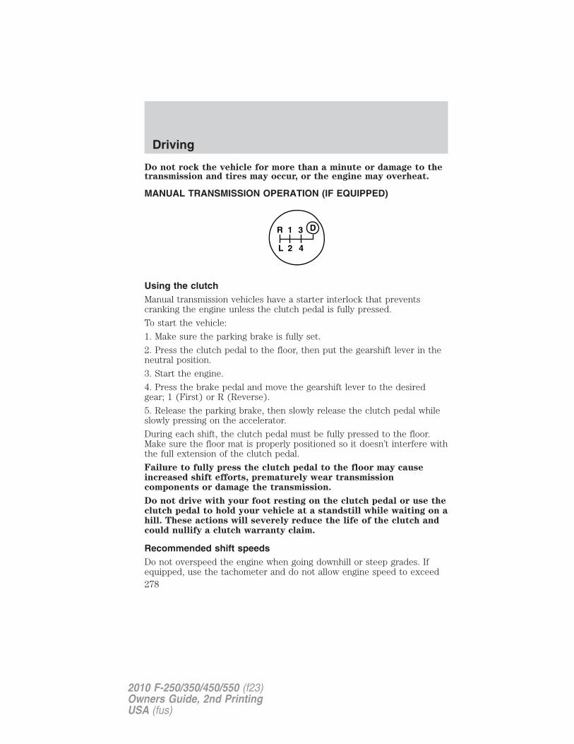
Do not rock the vehicle for more than a minute or damage to thetransmission and tires may occur, or the engine may overheat.
MANUAL TRANSMISSION OPERATION (IF EQUIPPED)
Using the clutchManual transmission vehicles have a starter interlock that preventscranking the engine unless the clutch pedal is fully pressed.
To start the vehicle:
1. Make sure the parking brake is fully set.
2. Press the clutch pedal to the floor, then put the gearshift lever in theneutral position.
3. Start the engine.
4. Press the brake pedal and move the gearshift lever to the desiredgear; 1 (First) or R (Reverse).
5. Release the parking brake, then slowly release the clutch pedal whileslowly pressing on the accelerator.
During each shift, the clutch pedal must be fully pressed to the floor.Make sure the floor mat is properly positioned so it doesn’t interfere withthe full extension of the clutch pedal.
Failure to fully press the clutch pedal to the floor may causeincreased shift efforts, prematurely wear transmissioncomponents or damage the transmission.
Do not drive with your foot resting on the clutch pedal or use theclutch pedal to hold your vehicle at a standstill while waiting on ahill. These actions will severely reduce the life of the clutch andcould nullify a clutch warranty claim.
Recommended shift speedsDo not overspeed the engine when going downhill or steep grades. Ifequipped, use the tachometer and do not allow engine speed to exceed
1
2 4
R
L
3 D
Driving
278
2010 F-250/350/450/550 (f23)Owners Guide, 2nd PrintingUSA (fus)
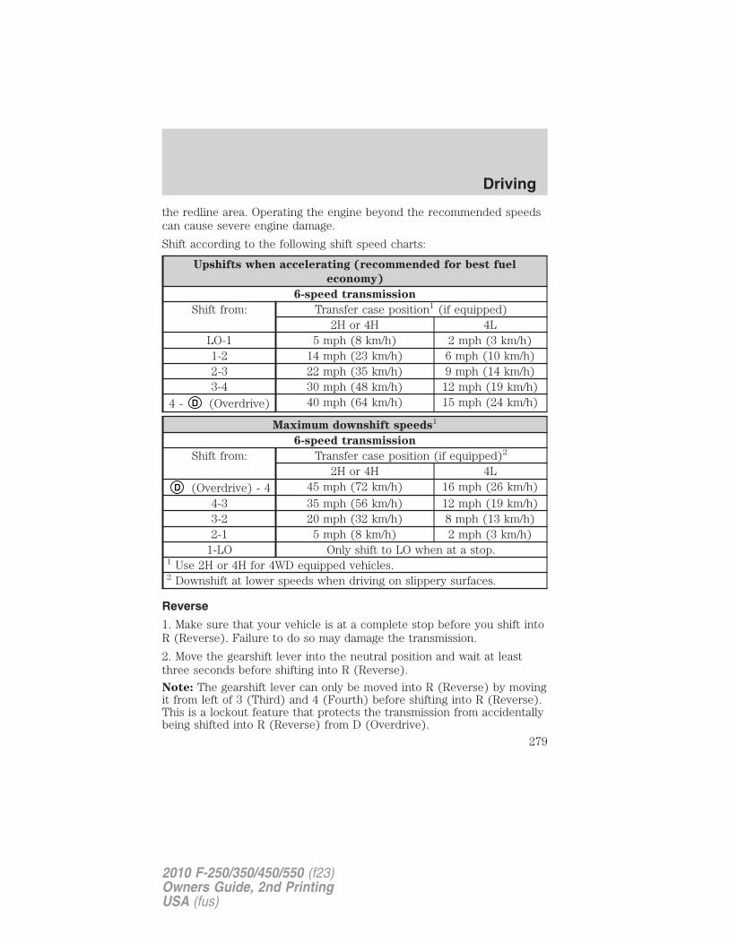
the redline area. Operating the engine beyond the recommended speedscan cause severe engine damage.
Shift according to the following shift speed charts:
Upshifts when accelerating (recommended for best fuel
economy)
6-speed transmission
Shift from: Transfer case position1 (if equipped)2H or 4H 4L
LO-1 5 mph (8 km/h) 2 mph (3 km/h)1-2 14 mph (23 km/h) 6 mph (10 km/h)2-3 22 mph (35 km/h) 9 mph (14 km/h)3-4 30 mph (48 km/h) 12 mph (19 km/h)
4 - D (Overdrive) 40 mph (64 km/h) 15 mph (24 km/h)
Maximum downshift speeds1
6-speed transmission
Shift from: Transfer case position (if equipped)2
2H or 4H 4LD (Overdrive) - 4 45 mph (72 km/h) 16 mph (26 km/h)
4-3 35 mph (56 km/h) 12 mph (19 km/h)3-2 20 mph (32 km/h) 8 mph (13 km/h)2-1 5 mph (8 km/h) 2 mph (3 km/h)
1-LO Only shift to LO when at a stop.1 Use 2H or 4H for 4WD equipped vehicles.2 Downshift at lower speeds when driving on slippery surfaces.
Reverse
1. Make sure that your vehicle is at a complete stop before you shift intoR (Reverse). Failure to do so may damage the transmission.
2. Move the gearshift lever into the neutral position and wait at leastthree seconds before shifting into R (Reverse).
Note: The gearshift lever can only be moved into R (Reverse) by movingit from left of 3 (Third) and 4 (Fourth) before shifting into R (Reverse).This is a lockout feature that protects the transmission from accidentallybeing shifted into R (Reverse) from D (Overdrive).
Driving
279
2010 F-250/350/450/550 (f23)Owners Guide, 2nd PrintingUSA (fus)
Parking your vehicle
1. Apply the brake and shift into the neutral position.
2. Fully apply the parking brake, then shift into 1 (First).
3. Turn the ignition off.
WARNING: Do not park your vehicle in Neutral, it may moveunexpectedly and injure someone. Use 1 (First) gear and set the
parking brake fully.
REVERSE SENSING SYSTEM (IF EQUIPPED)
The reverse sensing system (RSS) sounds a tone to warn the driver ofobstacles near the rear bumper when the R (Reverse) is selected and thevehicle is moving at speeds less than 3 mph (5 km/h). The system is noteffective at speeds above 3 mph (5 km/h) and may not detect certainangular or moving objects.
WARNING: To help avoid personal injury, please read andunderstand the limitations of the reverse sensing system as
contained in this section. Reverse sensing is only an aid for some(generally large and fixed) objects when moving in reverse on a flatsurface at “parking speeds”. Inclement weather may also affect thefunction of the RSS; this may include reduced performance or a falseactivation.
WARNING: To help avoid personal injury, always use cautionwhen in reverse and when using the RSS.
WARNING: This system is not designed to prevent contact withsmall or moving objects. The system is designed to provide a
warning to assist the driver in detecting large stationary objects toavoid damaging the vehicle. The system may not detect smallerobjects, particularly those close to the ground.
WARNING: Certain add-on devices such as large trailer hitches,bike or surfboard racks and any device that may block the
normal detection zone of the RSS system may create false beeps.
Driving
280
2010 F-250/350/450/550 (f23)Owners Guide, 2nd PrintingUSA (fus)
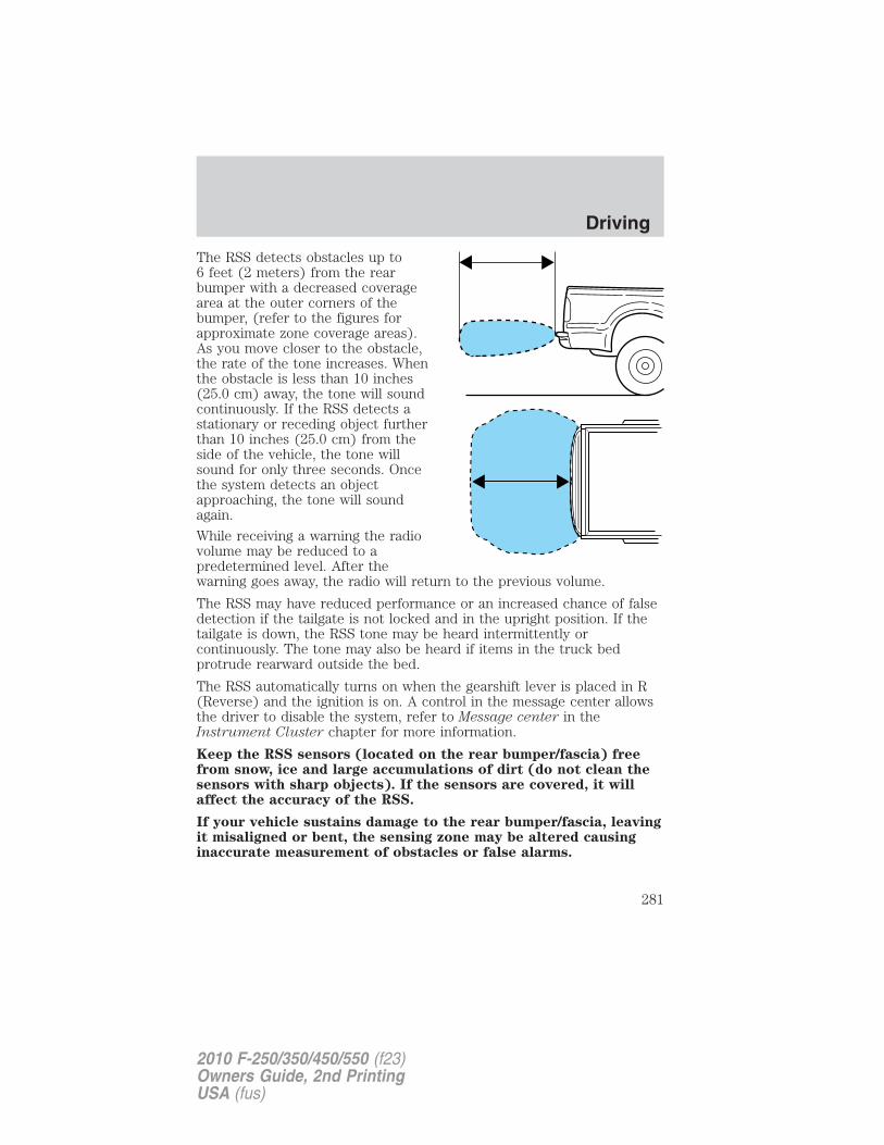
The RSS detects obstacles up to6 feet (2 meters) from the rearbumper with a decreased coveragearea at the outer corners of thebumper, (refer to the figures forapproximate zone coverage areas).As you move closer to the obstacle,the rate of the tone increases. Whenthe obstacle is less than 10 inches(25.0 cm) away, the tone will soundcontinuously. If the RSS detects astationary or receding object furtherthan 10 inches (25.0 cm) from theside of the vehicle, the tone willsound for only three seconds. Oncethe system detects an objectapproaching, the tone will soundagain.
While receiving a warning the radiovolume may be reduced to apredetermined level. After thewarning goes away, the radio will return to the previous volume.
The RSS may have reduced performance or an increased chance of falsedetection if the tailgate is not locked and in the upright position. If thetailgate is down, the RSS tone may be heard intermittently orcontinuously. The tone may also be heard if items in the truck bedprotrude rearward outside the bed.
The RSS automatically turns on when the gearshift lever is placed in R(Reverse) and the ignition is on. A control in the message center allowsthe driver to disable the system, refer to Message center in theInstrument Cluster chapter for more information.
Keep the RSS sensors (located on the rear bumper/fascia) freefrom snow, ice and large accumulations of dirt (do not clean thesensors with sharp objects). If the sensors are covered, it willaffect the accuracy of the RSS.
If your vehicle sustains damage to the rear bumper/fascia, leavingit misaligned or bent, the sensing zone may be altered causinginaccurate measurement of obstacles or false alarms.
Driving
281
2010 F-250/350/450/550 (f23)Owners Guide, 2nd PrintingUSA (fus)
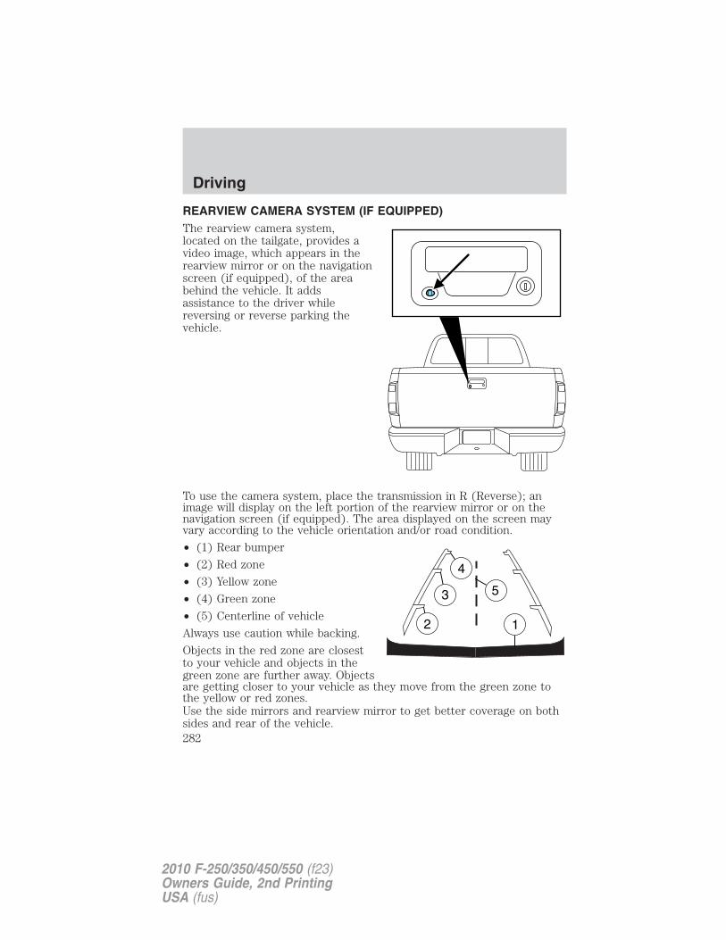
REARVIEW CAMERA SYSTEM (IF EQUIPPED)The rearview camera system,located on the tailgate, provides avideo image, which appears in therearview mirror or on the navigationscreen (if equipped), of the areabehind the vehicle. It addsassistance to the driver whilereversing or reverse parking thevehicle.
To use the camera system, place the transmission in R (Reverse); animage will display on the left portion of the rearview mirror or on thenavigation screen (if equipped). The area displayed on the screen mayvary according to the vehicle orientation and/or road condition.
• (1) Rear bumper
• (2) Red zone
• (3) Yellow zone
• (4) Green zone
• (5) Centerline of vehicle
Always use caution while backing.
Objects in the red zone are closestto your vehicle and objects in thegreen zone are further away. Objectsare getting closer to your vehicle as they move from the green zone tothe yellow or red zones.Use the side mirrors and rearview mirror to get better coverage on bothsides and rear of the vehicle.
Driving
282
2010 F-250/350/450/550 (f23)Owners Guide, 2nd PrintingUSA (fus)
When shifting out of R (Reverse) and into any other gear, the image willremain on for a few seconds before it shuts off to assist in parking ortrailer hookup.If equipped with the navigation system, after shifting out of R (Reverse)and into any gear other than P (Park), the image will remain until thevehicle speed reaches 5 mph (8 km/h), only if the rear camera delayfeature is on, or until any navigation radio button is pressed.Note: The default setting for the rear camera delay is off. Press the“Settings” button found on the navigation screen (if equipped) to set therear camera delay feature to on or off.When towing, the camera system will only see what is being towedbehind the vehicle; this might not provide adequate coverage as itusually provides in normal operation and some objects might not beseen.The camera lens for the camera is located on the tailgate, near thetailgate handle. Keep the lens clean so the video image remains clear andundistorted. Clean the lens with a soft, lint-free cloth and non-abrasivecleaner.
Note: If the camera system image is not clear or seems distorted, it maybe covered with water droplets, snow, mud or any other substance. Ifthis occurs, clean the camera lens before using the camera system.
WARNING: The camera system is a reverse aid supplementdevice that still requires the driver to use it in conjunction with
the rearview mirror and the side mirrors for maximum coverage.
WARNING: Objects that are close to either corner of thebumper or under the bumper, might not be seen on the screen
due to the limited coverage of the camera system.
WARNING: Backup as slow as possible since higher speedsmight limit your reaction time to stop the vehicle.
WARNING: Do not use the camera system with the tailgateopen.
If the back end of the vehicle is hit or damaged, then check with yourauthorized dealer to have your rear video system checked for propercoverage and operation.
Driving
283
2010 F-250/350/450/550 (f23)Owners Guide, 2nd PrintingUSA (fus)
Night time and dark area use
At night time or in dark areas, the camera system relies on the reverselamp lighting to produce an image. Therefore it is necessary that bothreverse lamps are operating in order to get a clear image in the dark. Ifeither of the lamps are not operating, stop using the camera system, atleast in the dark, until the lamp(s) are replaced and functioning.
Servicing
• If the image comes on while the vehicle is not in R (Reverse), havethe system inspected by your authorized dealer.
• If the image is not clear, then check if there is anything covering thelens such as dirt, mud, ice, snow, etc. If the image is still not clearafter cleaning, have your system inspected by your authorized dealer.
FOUR-WHEEL DRIVE (4WD) OPERATION (IF EQUIPPED)
WARNING: For important information regarding safe operationof this type of vehicle, see Preparing to drive your vehicle in
this chapter.
When four–wheel drive (4WD) is engaged, power is supplied to all fourwheels through a transfer case. 4WD can be selected when additionaldriving power is desired.
4WD operation is not recommended on dry pavement. Doing so couldresult in difficult disengagement of the transfer case, increased tire wearand decreased fuel economy.
Manual Shift On Stop (MSOS) 4x4 system (if equipped)The 4WD system is engaged ordisengaged by rotating the controlfor both front wheel hub locks fromthe FREE or LOCK position, thenmanually engaging or disengagingthe transfer case with thefloor-mounted shifter. For increasedfuel economy in 2WD, rotate bothhub locks to the FREE position.
Driving
284
2010 F-250/350/450/550 (f23)Owners Guide, 2nd PrintingUSA (fus)
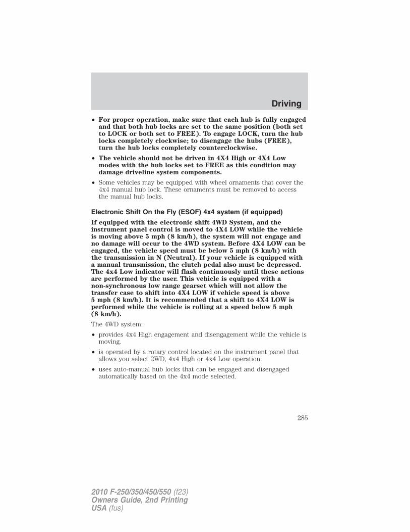
• For proper operation, make sure that each hub is fully engagedand that both hub locks are set to the same position (both setto LOCK or both set to FREE). To engage LOCK, turn the hublocks completely clockwise; to disengage the hubs (FREE),turn the hub locks completely counterclockwise.
• The vehicle should not be driven in 4X4 High or 4X4 Lowmodes with the hub locks set to FREE as this condition maydamage driveline system components.
• Some vehicles may be equipped with wheel ornaments that cover the4x4 manual hub lock. These ornaments must be removed to accessthe manual hub locks.
Electronic Shift On the Fly (ESOF) 4x4 system (if equipped)
If equipped with the electronic shift 4WD System, and theinstrument panel control is moved to 4X4 LOW while the vehicleis moving above 5 mph (8 km/h), the system will not engage andno damage will occur to the 4WD system. Before 4X4 LOW can beengaged, the vehicle speed must be below 5 mph (8 km/h) withthe transmission in N (Neutral). If your vehicle is equipped witha manual transmission, the clutch pedal also must be depressed.The 4x4 Low indicator will flash continuously until these actionsare performed by the user. This vehicle is equipped with anon-synchronous low range gearset which will not allow thetransfer case to shift into 4X4 LOW if vehicle speed is above5 mph (8 km/h). It is recommended that a shift to 4X4 LOW isperformed while the vehicle is rolling at a speed below 5 mph(8 km/h).
The 4WD system:
• provides 4x4 High engagement and disengagement while the vehicle ismoving.
• is operated by a rotary control located on the instrument panel thatallows you select 2WD, 4x4 High or 4x4 Low operation.
• uses auto-manual hub locks that can be engaged and disengagedautomatically based on the 4x4 mode selected.
Driving
285
2010 F-250/350/450/550 (f23)Owners Guide, 2nd PrintingUSA (fus)
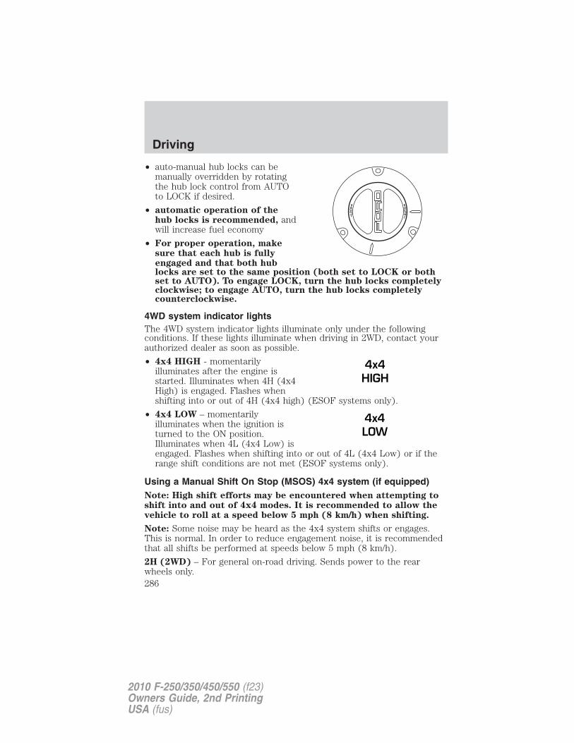
• auto-manual hub locks can bemanually overridden by rotatingthe hub lock control from AUTOto LOCK if desired.
• automatic operation of thehub locks is recommended, andwill increase fuel economy
• For proper operation, makesure that each hub is fullyengaged and that both hublocks are set to the same position (both set to LOCK or bothset to AUTO). To engage LOCK, turn the hub locks completelyclockwise; to engage AUTO, turn the hub locks completelycounterclockwise.
4WD system indicator lightsThe 4WD system indicator lights illuminate only under the followingconditions. If these lights illuminate when driving in 2WD, contact yourauthorized dealer as soon as possible.
• 4x4 HIGH - momentarilyilluminates after the engine isstarted. Illuminates when 4H (4x4High) is engaged. Flashes whenshifting into or out of 4H (4x4 high) (ESOF systems only).
• 4x4 LOW – momentarilyilluminates when the ignition isturned to the ON position.Illuminates when 4L (4x4 Low) isengaged. Flashes when shifting into or out of 4L (4x4 Low) or if therange shift conditions are not met (ESOF systems only).
Using a Manual Shift On Stop (MSOS) 4x4 system (if equipped)Note: High shift efforts may be encountered when attempting toshift into and out of 4x4 modes. It is recommended to allow thevehicle to roll at a speed below 5 mph (8 km/h) when shifting.
Note: Some noise may be heard as the 4x4 system shifts or engages.This is normal. In order to reduce engagement noise, it is recommendedthat all shifts be performed at speeds below 5 mph (8 km/h).
2H (2WD) – For general on-road driving. Sends power to the rearwheels only.
4x4HIGH
4x4LOW
Driving
286
2010 F-250/350/450/550 (f23)Owners Guide, 2nd PrintingUSA (fus)
4H (4x4 High) – For winter and off-road conditions. Sends power tofront and rear wheels. This mode is not intended for use on drypavement.
N (Neutral) – Only used when towing the vehicle.
4L (4x4 Low) – For low-speed off-road applications that require extrapower such as steep grades, deep sand or pulling a boat out of the water.Sends power to front and rear wheels. This mode is not intended foruse on dry pavement.
Shifting from 2H (2WD) to 4H (4x4 High)Engage the locking hubs by rotatingthe hub lock control from FREE toLOCK, then move the transfer caselever from 2H (2WD) to 4H (4x4High) at a stop or a vehicle speedbelow 5 mph (8 km/h).
• For proper operation, makesure that both indicatorarrows on the hub are aligned,and that both hubs are set toLOCK.
• Do not shift into 4H (4x4High) with the rear wheelsslipping.
2H4H
4LN
Driving
287
2010 F-250/350/450/550 (f23)Owners Guide, 2nd PrintingUSA (fus)
Shifting from 2H (2WD) to 4H (4x4 High)Engage the locking hubs by rotatingthe hub lock control from FREE toLOCK, then move the transfer caselever from 2H (2WD) to 4H (4x4High) at a stop or a vehicle speedbelow 3 mph (5 km/h).
• For proper operation, makesure that both indicatorarrows on the hub are aligned,and that both hubs are set toLOCK.
• Do not shift into 4H (4x4High) with the rear wheelsslipping.
Shifting from 4H (4x4 High) to 2H (2WD)Move the transfer case lever to 2H(2WD) at a stop or a vehicle speedbelow 5 mph (8 km/h).
With the vehicle at complete stop,disengage the locking hubs(optional) by rotating the hub lockcontrol from LOCK to FREE.
• For proper operation, makesure that both indicator arrows on the hub are aligned, andthat both hubs are set to FREE
Shifting from 4H (4x4 High) to 4L (4x4 Low)
1. Bring the vehicle to a stop or a speed below 5 mph (8 km/h).
2. Place the gearshift lever in N (Neutral). If the vehicle is equipped witha manual transmission, also depress the clutch pedal.
2H4H
4LN
2H4H
4LN
Driving
288
2010 F-250/350/450/550 (f23)Owners Guide, 2nd PrintingUSA (fus)
3. Move the transfer case shift leverthrough N (Neutral) directly to 4L(4x4 Low).
4. If the shift lever does not, or onlypartially moves to the 4L (4x4 Low)position, perform a shift with thetransmission in N (Neutral) (orclutch pedal depressed) and thevehicle rolling at a speed below 5 mph (8 km/h). This will ensure thetransfer case is fully engaged into 4L (4x4 Low).
Shifting from 4L (4x4 Low) to 4H (4x4 High) or 2H (2WD)
1. Bring the vehicle to a stop or a speed below 5 mph (8 km/h).
2. Place the gearshift lever in N (Neutral). If the vehicle is equipped witha manual transmission, also depress the clutch pedal.
3. Move the transfer case shift leverthrough N (Neutral) directly to 4H(4x4 High) or 2H (2WD).
4. If the transfer case will notengage into 4H (4x4 High) or 2H(2WD), perform a shift with thetransmission in N (Neutral) (orclutch pedal depressed) and thevehicle rolling at a speed below 5 mph (8 km/h).
5. If shifting to 2H (2WD) with the vehicle at a complete stop, disengagethe locking hubs (optional) by rotating the hub lock control from LOCKto FREE.
Using the N (Neutral) positionThe transfer case neutralposition overrides thetransmission and puts thevehicle in neutral regardless oftransmission gearshift leverposition. The vehicle can moveforward or backwards.
This position should only be usedwhen towing the vehicle.
2H4H
4LN
2H4H
4LN
2H4H
4LN
Driving
289
2010 F-250/350/450/550 (f23)Owners Guide, 2nd PrintingUSA (fus)
WARNING: Do not leave the vehicle unattended with thetransfer case in the N (Neutral) position. Always set the parking
brake fully and turn off the ignition when leaving the vehicle.
Using the Electronic Shift On the Fly (ESOF) 4x4 system(if equipped)
Positions of the electronic shift system
Note: Some noise may be heard as the 4WD system shifts or engages.This is normal.
2WD – For general on-road driving. Sends power to the rear wheels only.
4x4 HIGH – For winter and off-road conditions. Sends power to frontand rear wheels. This mode is not intended for use on drypavement.
4x4 LOW – For low-speed off-road applications that require extra powersuch as steep grades, deep sand or pulling a boat out of the water. Sendspower to front and rear wheels. This mode is not intended for use ondry pavement.
Shifting from 2WD to 4x4 HIGHRotate the 4x4 control to the 4x4HIGH position at speeds up to55 mph (88 km/h).
• The electronic shift 4x4system is designed to engage4x4 HIGH when the vehicle ismoving. If shifted to 4x4HIGH while at complete stop,4x4 may not engage and the4x4 indicator may flashcontinuously until the vehicleis allowed to move at a speed above 1 mph (1.6 km/h).
• Do not shift into 4x4 HIGH with the rear wheels slipping.
Driving
290
2010 F-250/350/450/550 (f23)Owners Guide, 2nd PrintingUSA (fus)
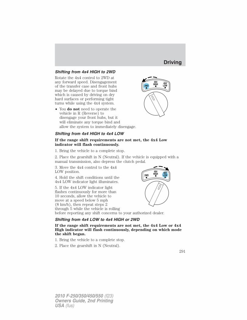
Shifting from 4x4 HIGH to 2WDRotate the 4x4 control to 2WD atany forward speed. Disengagementof the transfer case and front hubsmay be delayed due to torque bindwhich is caused by driving on dryhard surfaces or performing tightturns while using the 4x4 system.
• You do not need to operate thevehicle in R (Reverse) todisengage your front hubs, but itwill eliminate any torque bind andallow the system to immediately disengage.
Shifting from 4x4 HIGH to 4x4 LOW
If the range shift requirements are not met, the 4x4 Low
indicator will flash continuously.
1. Bring the vehicle to a complete stop.
2. Place the gearshift in N (Neutral). If the vehicle is equipped with amanual transmission, also depress the clutch pedal.
3. Move the 4x4 control to the 4x4LOW position.
4. Hold the shift conditions until the4x4 LOW indicator light illuminates.
5. If the 4x4 LOW indicator lightflashes continuously for more than10 seconds, allow the vehicle tomove at a speed below 5 mph(8 km/h), then repeat steps 2through 5 while the vehicle is rollingbefore reporting any shift concerns to your authorized dealer.
Shifting from 4x4 LOW to 4x4 HIGH or 2WDIf the range shift requirements are not met, the 4x4 Low or 4x4High indicator will flash continuously, depending on which modethe shift began.
1. Bring the vehicle to a complete stop.
2. Place the gearshift in N (Neutral).
Driving
291
2010 F-250/350/450/550 (f23)Owners Guide, 2nd PrintingUSA (fus)
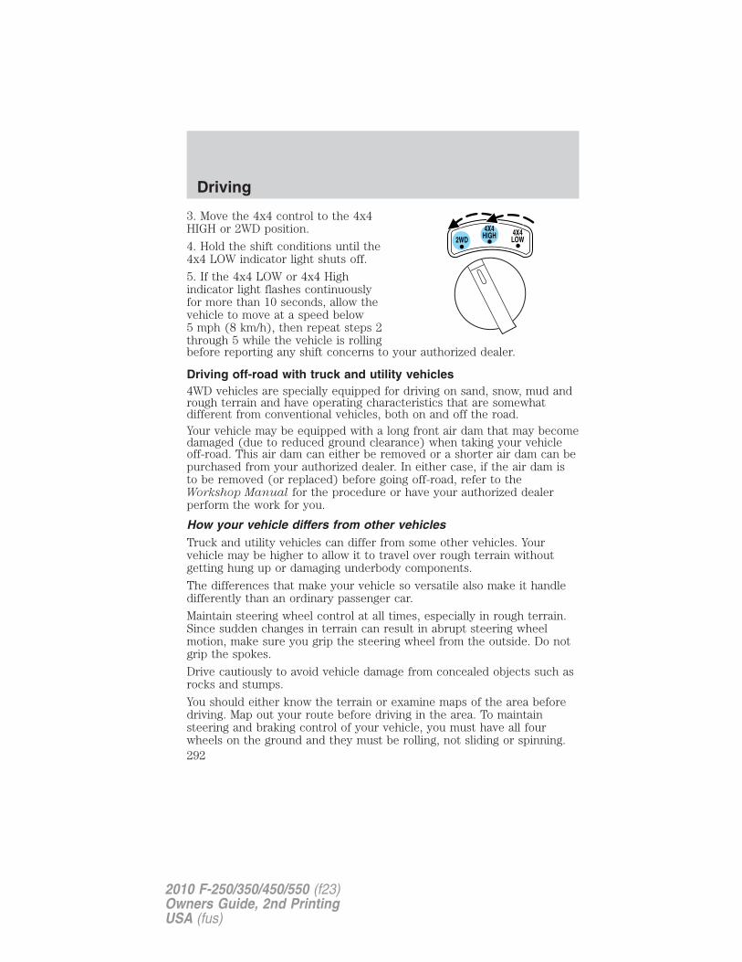
3. Move the 4x4 control to the 4x4HIGH or 2WD position.
4. Hold the shift conditions until the4x4 LOW indicator light shuts off.
5. If the 4x4 LOW or 4x4 Highindicator light flashes continuouslyfor more than 10 seconds, allow thevehicle to move at a speed below5 mph (8 km/h), then repeat steps 2through 5 while the vehicle is rollingbefore reporting any shift concerns to your authorized dealer.
Driving off-road with truck and utility vehicles4WD vehicles are specially equipped for driving on sand, snow, mud andrough terrain and have operating characteristics that are somewhatdifferent from conventional vehicles, both on and off the road.Your vehicle may be equipped with a long front air dam that may becomedamaged (due to reduced ground clearance) when taking your vehicleoff-road. This air dam can either be removed or a shorter air dam can bepurchased from your authorized dealer. In either case, if the air dam isto be removed (or replaced) before going off-road, refer to theWorkshop Manual for the procedure or have your authorized dealerperform the work for you.
How your vehicle differs from other vehiclesTruck and utility vehicles can differ from some other vehicles. Yourvehicle may be higher to allow it to travel over rough terrain withoutgetting hung up or damaging underbody components.
The differences that make your vehicle so versatile also make it handledifferently than an ordinary passenger car.
Maintain steering wheel control at all times, especially in rough terrain.Since sudden changes in terrain can result in abrupt steering wheelmotion, make sure you grip the steering wheel from the outside. Do notgrip the spokes.
Drive cautiously to avoid vehicle damage from concealed objects such asrocks and stumps.
You should either know the terrain or examine maps of the area beforedriving. Map out your route before driving in the area. To maintainsteering and braking control of your vehicle, you must have all fourwheels on the ground and they must be rolling, not sliding or spinning.
Driving
292
2010 F-250/350/450/550 (f23)Owners Guide, 2nd PrintingUSA (fus)
Basic operating principles• Do not use 4WD on dry, hard surfaced roads. Doing so will produce
excessive noise, increase tire wear and may damage drive components.4WD modes are only intended for consistently slippery or loosesurfaces.
• Drive slower in strong crosswinds which can affect the normal steeringcharacteristics of your vehicle.
• Be extremely careful when driving on pavement made slippery byloose sand, water, gravel, snow or ice.
If your vehicle goes off the edge of the pavement• If your vehicle goes off the edge of the pavement, slow down, but
avoid severe brake application, ease the vehicle back onto thepavement only after reducing your speed. Do not turn the steeringwheel too sharply while returning to the road surface.
• It may be safer to stay on the apron or shoulder of the road and slowdown gradually before returning to the pavement. You may losecontrol if you do not slow down or if you turn the steering wheel toosharply or abruptly.
• It often may be less risky to strike small objects, such as highwayreflectors, with minor damage to your vehicle rather than attempt asudden return to the pavement which could cause the vehicle to slidesideways out of control or roll over. Remember, your safety and thesafety of others should be your primary concern.
WARNING: Vehicles with a higher center of gravity such asutility and four-wheel drive vehicles handle differently than
vehicles with a lower center of gravity. Utility and four-wheel drivevehicles are not designed for cornering at speeds as high as passengercars any more than low-slung sports cars are designed to performsatisfactorily under off-road conditions. Avoid sharp turns, excessivespeed and abrupt maneuvers in these vehicles. Failure to drivecautiously could result in an increased risk of loss of vehicle control,vehicle rollover, personal injury and death.
If your vehicle gets stuckIf your vehicle gets stuck in mud or snow it may be rocked out byshifting between forward and reverse gears, stopping between shifts, in asteady pattern. Press lightly on the accelerator in each gear.
Do not rock the vehicle if the engine is not at normal operatingtemperature or damage to the transmission may occur.
Driving
293
2010 F-250/350/450/550 (f23)Owners Guide, 2nd PrintingUSA (fus)
Do not rock the vehicle for more than a few minutes or damageto the transmission and tires may occur or the engine mayoverheat.
WARNING: Do not spin the wheels at over 35 mph (56 km/h).The tires may fail and injure a passenger or bystander.
Refer to Transmission fluid temperature gauge in the InstrumentCluster chapter for transmission fluid temperature information.
Emergency maneuvers• In an unavoidable emergency situation where a sudden sharp turn
must be made, remember to avoid “over-driving” your vehicle, i.e.,turn the steering wheel only as rapidly and as far as required to avoidthe emergency. Excessive steering will result in less vehicle control,not more. Additionally, smooth variations of the accelerator and/orbrake pedal pressure should be utilized if changes in vehicle speed arecalled for. Avoid abrupt steering, acceleration or braking which couldresult in an increased risk of loss of vehicle control, vehicle rolloverand/or personal injury. Use all available road surface to return thevehicle to a safe direction of travel.
• In the event of an emergency stop, avoid skidding the tires and do notattempt any sharp steering wheel movements.
WARNING: Vehicles with a higher center of gravity such asutility and four-wheel drive vehicles handle differently than
vehicles with a lower center of gravity. Utility and four-wheel drivevehicles are not designed for cornering at speeds as high as passengercars any more than low-slung sports cars are designed to performsatisfactorily under off-road conditions. Avoid sharp turns, excessivespeed and abrupt maneuvers in these vehicles. Failure to drivecautiously could result in an increased risk of loss of vehicle control,vehicle rollover, personal injury and death.
• If the vehicle goes from one type of surface to another (i.e., fromconcrete to gravel) there will be a change in the way the vehicleresponds to a maneuver (steering, acceleration or braking). Again,avoid these abrupt inputs.
ParkingOn some 4WD vehicles, when the transfer case is in the N (Neutral)position, the engine and transmission are disconnected from the rest of
Driving
294
2010 F-250/350/450/550 (f23)Owners Guide, 2nd PrintingUSA (fus)
the driveline. Therefore, the vehicle is free to roll even if the automatictransmission is in P (Park) or the manual transmission is in gear. Do notleave the vehicle unattended with the transfer case in the N (Neutral)position. Always set the parking brake fully and turn off the ignitionwhen leaving the vehicle.
WARNING: Always set the parking brake fully and make surethe gearshift is latched in P (Park). Turn the ignition to the off
position and remove the key whenever you leave your vehicle.
WARNING: If the parking brake is fully released, but the brakewarning lamp remains illuminated, the brakes may not be
working properly. See your authorized dealer.
4WD Systems4WD (when you select a 4WD mode), uses all four wheels to power thevehicle. This increases traction, enabling you to drive over terrain androad conditions that a conventional two-wheel drive vehicle cannot.Power is supplied to all four wheels through a transfer case. On 4WDvehicles, the transfer case allows you to select 4WD when necessary.Information on transfer case operation and shifting procedures can befound in the Driving chapter. Information on transfer case maintenancecan be found in the Maintenance and Specifications chapter. Youshould become thoroughly familiar with this information before youoperate your vehicle.
Normal characteristicsOn some 4WD models, the initial shift from two-wheel drive to 4x4 whilethe vehicle is moving can cause some momentary clunk and ratchetingsounds. This is the front drivetrain coming up to speed and theautomatic locking hubs engaging and is not cause for concern.
SandWhen driving over sand, try to keep all four wheels on the most solidarea of the trail. Avoid reducing the tire pressures but shift to a lowergear and drive steadily through the terrain. Apply the accelerator slowlyand avoid spinning the wheels.
Avoid excessive speed because vehicle momentum can work against youand cause the vehicle to become stuck to the point that assistance maybe required from another vehicle. Remember, you may be able to backout the way you came if you proceed with caution.
Driving
295
2010 F-250/350/450/550 (f23)Owners Guide, 2nd PrintingUSA (fus)
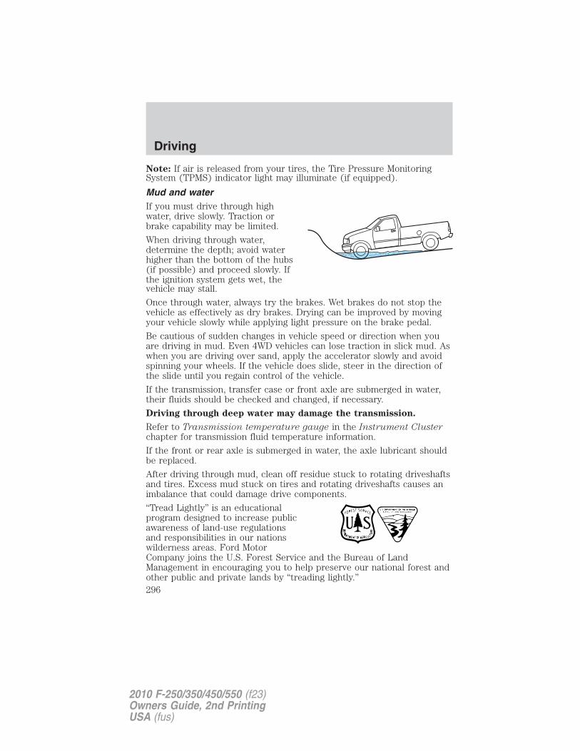
Note: If air is released from your tires, the Tire Pressure MonitoringSystem (TPMS) indicator light may illuminate (if equipped).
Mud and waterIf you must drive through highwater, drive slowly. Traction orbrake capability may be limited.
When driving through water,determine the depth; avoid waterhigher than the bottom of the hubs(if possible) and proceed slowly. Ifthe ignition system gets wet, thevehicle may stall.
Once through water, always try the brakes. Wet brakes do not stop thevehicle as effectively as dry brakes. Drying can be improved by movingyour vehicle slowly while applying light pressure on the brake pedal.
Be cautious of sudden changes in vehicle speed or direction when youare driving in mud. Even 4WD vehicles can lose traction in slick mud. Aswhen you are driving over sand, apply the accelerator slowly and avoidspinning your wheels. If the vehicle does slide, steer in the direction ofthe slide until you regain control of the vehicle.
If the transmission, transfer case or front axle are submerged in water,their fluids should be checked and changed, if necessary.
Driving through deep water may damage the transmission.
Refer to Transmission temperature gauge in the Instrument Clusterchapter for transmission fluid temperature information.
If the front or rear axle is submerged in water, the axle lubricant shouldbe replaced.
After driving through mud, clean off residue stuck to rotating driveshaftsand tires. Excess mud stuck on tires and rotating driveshafts causes animbalance that could damage drive components.
“Tread Lightly” is an educationalprogram designed to increase publicawareness of land-use regulationsand responsibilities in our nationswilderness areas. Ford MotorCompany joins the U.S. Forest Service and the Bureau of LandManagement in encouraging you to help preserve our national forest andother public and private lands by “treading lightly.”
Driving
296
2010 F-250/350/450/550 (f23)Owners Guide, 2nd PrintingUSA (fus)
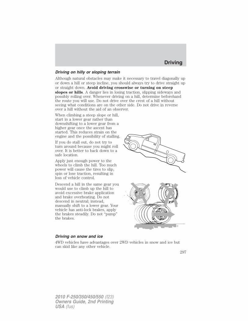
Driving on hilly or sloping terrain
Although natural obstacles may make it necessary to travel diagonally upor down a hill or steep incline, you should always try to drive straight upor straight down. Avoid driving crosswise or turning on steep
slopes or hills. A danger lies in losing traction, slipping sideways andpossibly rolling over. Whenever driving on a hill, determine beforehandthe route you will use. Do not drive over the crest of a hill withoutseeing what conditions are on the other side. Do not drive in reverseover a hill without the aid of an observer.
When climbing a steep slope or hill,start in a lower gear rather thandownshifting to a lower gear from ahigher gear once the ascent hasstarted. This reduces strain on theengine and the possibility of stalling.
If you do stall out, do not try toturn around because you might rollover. It is better to back down to asafe location.
Apply just enough power to thewheels to climb the hill. Too muchpower will cause the tires to slip,spin or lose traction, resulting inloss of vehicle control.
Descend a hill in the same gear youwould use to climb up the hill toavoid excessive brake applicationand brake overheating. Do notdescend in neutral; instead,manually shift to a lower gear. Yourvehicle has anti-lock brakes, applythe brakes steadily. Do not “pump”the brakes.
Driving on snow and ice4WD vehicles have advantages over 2WD vehicles in snow and ice butcan skid like any other vehicle.
Driving
297
2010 F-250/350/450/550 (f23)Owners Guide, 2nd PrintingUSA (fus)
Should you start to slide while driving on snowy or icy roads, turn thesteering wheel in the direction of the slide until you regain control.Avoid sudden applications of power and quick changes of direction onsnow and ice. Apply the accelerator slowly and steadily when startingfrom a full stop.Avoid sudden braking as well. Although a 4WD vehicle may acceleratebetter than a two-wheel drive vehicle in snow and ice, it won’t stop anyfaster, because as in other vehicles, braking occurs at all four wheels. Donot become overconfident as to road conditions.Make sure you allow sufficient distance between you and other vehiclesfor stopping. Drive slower than usual and consider using one of the lowergears. In emergency stopping situations, avoid locking of the wheels. Usea “squeeze” technique, push on the brake pedal with a steadily increasingforce which allows the wheels to brake yet continue to roll so that youmay steer in the direction you want to travel. If you lock the wheels,release the brake pedal and repeat the squeeze technique. If your vehicleis equipped with a Four Wheel Anti-Lock Brake System (ABS), apply thebrake steadily. Do not “pump” the brakes. Refer to the Brakes section ofthis chapter for additional information on the operation of the anti-lockbrake system.
WARNING: If you are driving in slippery conditions that requiretire cables, then it is critical that you drive cautiously. Keep
speeds down, allow for longer stopping distances and avoid aggressivesteering to reduce the chances of a loss of vehicle control which canlead to serious injury or death. If the rear end of the vehicle slideswhile cornering, steer in the direction of the slide until you regaincontrol of the vehicle.
Maintenance and ModificationsThe suspension and steering systems on your vehicle have been designedand tested to provide predictable performance whether loaded or emptyand durable load carrying capability. For this reason, Ford MotorCompany strongly recommends that you do not make modifications suchas adding or removing parts (such as lift kits or stabilizer bars) or byusing replacement parts not equivalent to the original factory equipment.
Any modifications to a vehicle that raise the center of gravity can makeit more likely the vehicle will roll over as a result of a loss of control.Ford Motor Company recommends that caution be used with any vehicleequipped with a high load or device (such as ladder racks or pickup boxcover).
Driving
298
2010 F-250/350/450/550 (f23)Owners Guide, 2nd PrintingUSA (fus)
Failure to maintain your vehicle properly may void the warranty, increaseyour repair cost, reduce vehicle performance and operational capabilitiesand adversely affect driver and passenger safety. Frequent inspection ofvehicle chassis components is recommended if the vehicle is subjected toheavy off-road usage.
VEHICLE USED AS A STATIONARY POWER SOURCEAuxiliary equipment called power take-off, or PTO, is often added to theengine or transmission to operate utility equipment. Examples include awheel-lift for tow trucks, cranes, tools for construction or tire service,and pumping fluids. PTO applications draw auxiliary horsepower fromthe powertrain, often while the vehicle is stationary. In this condition,there is limited cooling air flow through the radiator and around thevehicle that normally occurs when a vehicle is moving. The aftermarketPTO system installer, having the most knowledge of the final application,is responsible for determining whether additional chassis heat protectionor powertrain cooling is required, and alerting the user to the safe andproper operation.
Ford Super Duty Vehicles are qualified for use as a stationary powersource, within limits detailed in the Ford Truck Body Builders LayoutBook, found at www.fleet.ford.com/truckbbas, and through the FordTruck Body Builders Advisory Service.
Gas engine vehicles are qualified for up to 10 minutes of continuousoperation as a stationary power source, due to the potential for thenormal venting of fuel vapors. For stationary PTO operation of extendedduration (beyond 10 minutes), diesel engine is recommended. Furtherconsult your aftermarket PTO installer, since the duration of operationlimit for the aftermarket PTO may be less than the vehicle is capable of.
DRIVING THROUGH WATERIf driving through deep or standingwater is unavoidable, proceed veryslowly especially when the depth isnot known. Never drive throughwater that is higher than the bottomof the wheel rims (for cars) or thebottom of the hubs (for trucks).
When driving through water, traction or brake capability may be limited.Also, water may enter your engine’s air intake and severely damage yourengine or your vehicle may stall. Driving through deep water where
Driving
299
2010 F-250/350/450/550 (f23)Owners Guide, 2nd PrintingUSA (fus)
the transmission vent tube is submerged may allow water into thetransmission and cause internal transmission damage.
Once through the water, always dry the brakes by moving yourvehicle slowly while applying light pressure on the brake pedal.Wet brakes do not stop the vehicle as quickly as dry brakes.
SNOWPLOWINGFord recommends that the Super Duty F-Series used for snow removalinclude the Snow Plow Package Option.
Installing the snowplowWeight limits and guidelines for selecting and installing the snowplow canbe found in the Ford Truck Body Builders Layout Book, Snowplowsection, found at www.fleet.ford.com/truckbbas. A typical installationaffects the following:
• Certification to government safety laws such as occupant protectionand airbag deployment, braking, and lighting. Look for an “Alterer’sLabel” on the vehicle from the snowplow installer certifying that theinstallation meets all applicable Federal Motor Vehicle SafetyStandards (FMVSS).
• The Total Accessory Reserve Capacity (TARC) is shown on the lowerright side of the vehicle’s Safety Compliance Certification Label. Thisapplies to Ford-completed vehicles of 10,000 lb. (4,536 kg) GVWR orless. This is the weight of permanently-attached auxiliary equipment,such as snowplow frame-mounting hardware, that can be added to thevehicle and satisfy Ford compliance certification to FMVSS. Exceedingthis weight may require the auxiliary equipment installer additionalsafety certification responsibility. The Front Accessory ReserveCapacity (FARC) is added for customer convenience.
• Rear ballast weight behind the rear axle may be required to preventexceeding the FGAWR, and provide front-to-rear weight balance forproper braking and steering.
• Front wheel toe may require re-adjustment to prevent prematureuneven tire wear. Specifications are found in the Ford WorkshopManual.
• Headlight aim may require re-adjustment.
• The tire air pressures recommended for general driving are found onthe vehicle’s Safety Certification Label. The maximum cold inflationpressure for the tire and associated load rating is imprinted on the tire
Driving
300
2010 F-250/350/450/550 (f23)Owners Guide, 2nd PrintingUSA (fus)
sidewall. Tire air pressure may require re-adjustment within thesepressure limits to accommodate the additional weight of the snowplowinstallation.
• Federal and some local regulations require additional exterior lampsfor snowplow-equipped vehicles. Consult your authorized dealer foradditional information.
• The snow plow prep package includes a unique powertrain controlstrategy which is required for diesel engine cooling during highwaydriving with the snowplow raised.
Operating the vehicle with the snowplow attachedDo not use your vehicle for snow removal until it has been driven atleast 500 miles (800 km).
The attached snowplow blade restricts airflow to the radiator, and maycause the engine to run at a higher temperature: Attention to enginetemperature is especially important when outside temperatures areabove freezing. Angle the blade to maximize airflow to the radiator andmonitor engine temperature to determine whether a left or right angleprovides the best performance.
Follow the severe duty schedule in your scheduled maintenanceinformation for engine oil and transmission fluid change intervals.
Snowplowing with your airbag-equipped vehicleYour vehicle is equipped with a driver and passenger airbagSupplemental Restraint System (SRS) The SRS is designed to activate incertain frontal and offset frontal collisions when the vehicle sustainssufficient longitudinal deceleration.
Careless or high speed driving while plowing snow which results insufficient vehicle decelerations can deploy the airbag. Such driving alsoincreases the risk of accidents.
WARNING: All occupants of the vehicle, including the driver,should always properly wear their safety belts, even when an air
bag supplemental restraint system (SRS) is provided.
Never remove or defeat the “tripping mechanisms” designed into thesnow removal equipment by its manufacturer. Doing so may causedamage to the vehicle and the snow removal equipment as well aspossible airbag deployment.
Driving
301
2010 F-250/350/450/550 (f23)Owners Guide, 2nd PrintingUSA (fus)
WARNING: Do not attempt to service, repair, or modify the airbag supplemental restraint system (SRS) or its fuses. See your
Ford or Lincoln Mercury dealer.
WARNING: Additional equipment such as snowplow equipmentmay effect the performance of the airbag sensors increasing the
risk of injury. Please refer to the Body Builders Layout Book forinstructions about the appropriate installation of additional equipment.
Transmission operation while plowingOperate the vehicle with the automatic transmission gearshift lever inthe D (Overdrive) position and Tow/Haul off.
• Shift transfer case to 4x4 LOW (4WD Low) when plowing in smallareas at speeds below 5 mph (8 km/h).
• Shift transfer case to 4x4 HIGH (4WD High) when plowing largerareas or light snow at higher speeds. Do not exceed 15 mph(24 km/h).
• Do not shift the transmission from a forward gear to R (Reverse) untilthe engine is at idle and the wheels are stopped.
• If the vehicle is stuck, shift the transmission in a steady motionbetween forward and reverse gears. Do not rock the vehicle for morethan a few minutes. The transmission and tires may be damaged orthe engine can overheat.
Do not rock the vehicle if the engine is not at normal operatingtemperature. Do not rock the vehicle for more than a minute. Thetransmission and tires may be damaged or the engine mayoverheat.
Refer to Transmission temperature gauge in the Instrument Clusterchapter for transmission fluid temperature information.
WARNING: Do not spin the wheels at over 35 mph (55 km/h).The tires may fail and injure a passenger or bystander.
Driving
302
2010 F-250/350/450/550 (f23)Owners Guide, 2nd PrintingUSA (fus)
ROADSIDE ASSISTANCE
Getting roadside assistanceTo fully assist you should you have a vehicle concern, Ford MotorCompany offers a complimentary roadside assistance program. Thisprogram is separate from the New Vehicle Limited Warranty. The serviceis available:
• 24-hours, seven days a week
• for the coverage period listed on the Roadside Assistance Cardincluded in your Owner Guide portfolio.
Roadside assistance will cover:
• a flat tire change with a good spare (except vehicles that have beensupplied with a tire inflation kit)
• battery jump start
• lock-out assistance (key replacement cost is the customer’sresponsibility)
• fuel delivery – Independent Service Contractors, if not prohibited bystate, local or municipal law shall deliver up to 2.0 gallons (7.5L) ofgasoline or 5.0 gallons (18.9L) of diesel fuel to a disabled vehicle. Fueldelivery service is limited to two no-charge occurrences within a12-month period.
• winch out – available within 100 feet (30.5 meters) of a paved orcounty maintained road, no recoveries.
• towing – Ford/Mercury/Lincoln eligible vehicle towed to an authorizeddealer within 35 miles (56 km) of the disablement location or to thenearest authorized dealer. If a member requests to be towed to anauthorized dealer more than 35 miles (56 km) from the disablementlocation, the member shall be responsible for any mileage costs inexcess of 35 miles (56 km).
Trailers shall be covered up to $200 if the disabled eligible vehiclerequires service at the nearest authorized dealer. If the trailer is disabled,but the towing vehicle is operational, the trailer does not qualify for anyroadside services.
Canadian customers refer to your Customer Information Guidefor information on:
• coverage period
• exact fuel amounts
Roadside Emergencies
303
2010 F-250/350/450/550 (f23)Owners Guide, 2nd PrintingUSA (fus)
• towing of your disabled vehicle• emergency travel expense reimbursement• travel planning benefitsIn Canada, for uninterrupted Roadside Assistance coverage, you maypurchase extended coverage prior to your Basic Warranty’s RoadsideAssistance expiring. For more information and enrollment, contact1-877-294-2582 or visit our website at www.ford.ca.
Using roadside assistanceComplete the roadside assistance identification card and place it in yourwallet for quick reference. In the United States, this card is found in theOwner Guide portfolio in the glove compartment. In Canada, the card isfound in the Customer Information Guide in the glove compartment.
U.S. Ford, Mercury and Lincoln vehicle customers who require RoadsideAssistance, call 1-800-241-3673.
Canadian customers who require roadside assistance, call1-800-665-2006.
If you need to arrange roadside assistance for yourself, Ford MotorCompany will reimburse a reasonable amount for towing to the nearestdealership within 35 miles (56 km). To obtain reimbursementinformation, U.S. Ford, Mercury and Lincoln vehicle customers call1-800-241-3673. Customers will be asked to submit their originalreceipts.
Canadian customers who need to obtain reimbursement information, call1-800-665-2006.
HAZARD FLASHER CONTROLThe hazard flasher is located on thesteering column, just behind thesteering wheel. The hazard flasherswill operate when the ignition is inany position or if the key is not inthe ignition.
Press in the flasher control and allfront and rear direction signals willflash. Press the flasher control againto turn them off. Use it when yourvehicle is disabled and is creating asafety hazard for other motorists.
Roadside Emergencies
304
2010 F-250/350/450/550 (f23)Owners Guide, 2nd PrintingUSA (fus)
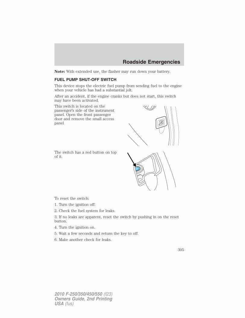
Note: With extended use, the flasher may run down your battery.
FUEL PUMP SHUT-OFF SWITCH
This device stops the electric fuel pump from sending fuel to the enginewhen your vehicle has had a substantial jolt.
After an accident, if the engine cranks but does not start, this switchmay have been activated.
This switch is located on thepassenger’s side of the instrumentpanel. Open the front passengerdoor and remove the small accesspanel
The switch has a red button on topof it.
To reset the switch:
1. Turn the ignition off.
2. Check the fuel system for leaks.
3. If no leaks are apparent, reset the switch by pushing in on the resetbutton.
4. Turn the ignition on.
5. Wait a few seconds and return the key to off.
6. Make another check for leaks.
Roadside Emergencies
305
2010 F-250/350/450/550 (f23)Owners Guide, 2nd PrintingUSA (fus)
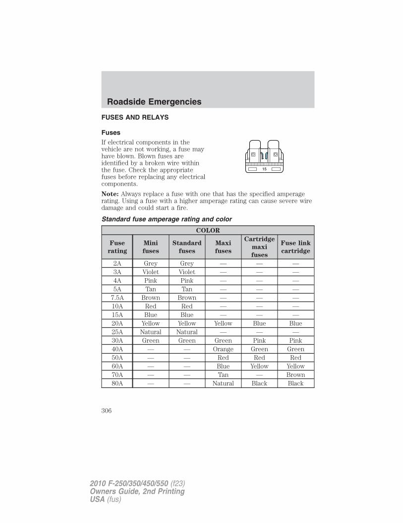
FUSES AND RELAYS
FusesIf electrical components in thevehicle are not working, a fuse mayhave blown. Blown fuses areidentified by a broken wire withinthe fuse. Check the appropriatefuses before replacing any electricalcomponents.
Note: Always replace a fuse with one that has the specified amperagerating. Using a fuse with a higher amperage rating can cause severe wiredamage and could start a fire.
Standard fuse amperage rating and color
COLOR
Fuse
rating
Mini
fuses
Standard
fuses
Maxi
fuses
Cartridge
maxi
fuses
Fuse link
cartridge
2A Grey Grey — — —3A Violet Violet — — —4A Pink Pink — — —5A Tan Tan — — —
7.5A Brown Brown — — —10A Red Red — — —15A Blue Blue — — —20A Yellow Yellow Yellow Blue Blue25A Natural Natural — — —30A Green Green Green Pink Pink40A — — Orange Green Green50A — — Red Red Red60A — — Blue Yellow Yellow70A — — Tan — Brown80A — — Natural Black Black
15
Roadside Emergencies
306
2010 F-250/350/450/550 (f23)Owners Guide, 2nd PrintingUSA (fus)
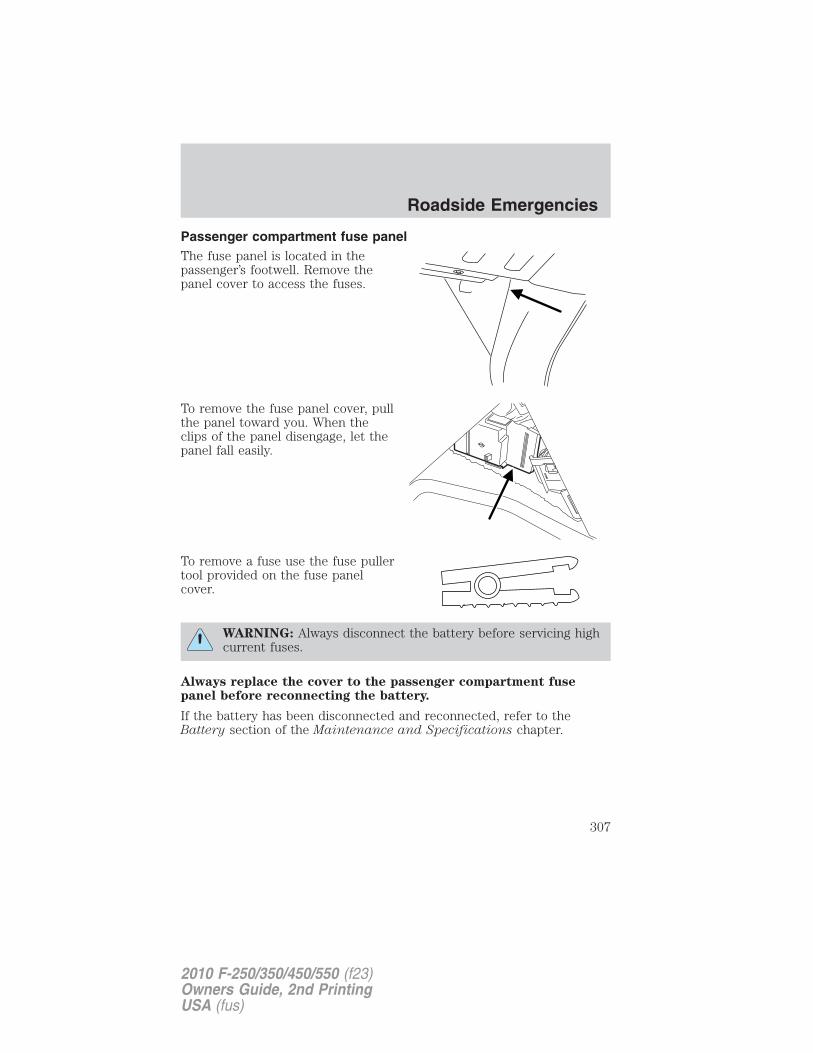
Passenger compartment fuse panelThe fuse panel is located in thepassenger’s footwell. Remove thepanel cover to access the fuses.
To remove the fuse panel cover, pullthe panel toward you. When theclips of the panel disengage, let thepanel fall easily.
To remove a fuse use the fuse pullertool provided on the fuse panelcover.
WARNING: Always disconnect the battery before servicing highcurrent fuses.
Always replace the cover to the passenger compartment fusepanel before reconnecting the battery.
If the battery has been disconnected and reconnected, refer to theBattery section of the Maintenance and Specifications chapter.
Roadside Emergencies
307
2010 F-250/350/450/550 (f23)Owners Guide, 2nd PrintingUSA (fus)
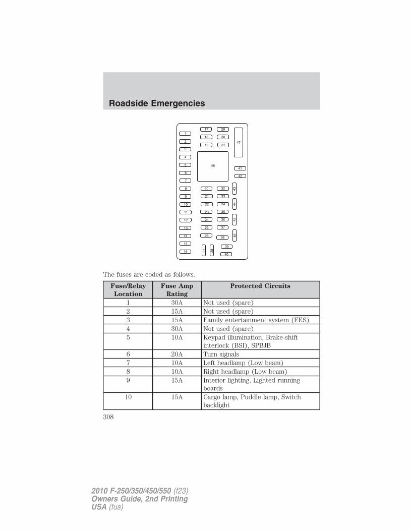
The fuses are coded as follows.
Fuse/Relay
Location
Fuse Amp
Rating
Protected Circuits
1 30A Not used (spare)2 15A Not used (spare)3 15A Family entertainment system (FES)4 30A Not used (spare)5 10A Keypad illumination, Brake-shift
interlock (BSI), SPBJB6 20A Turn signals7 10A Left headlamp (Low beam)8 10A Right headlamp (Low beam)9 15A Interior lighting, Lighted running
boards10 15A Cargo lamp, Puddle lamp, Switch
backlight
Roadside Emergencies
308
2010 F-250/350/450/550 (f23)Owners Guide, 2nd PrintingUSA (fus)
Fuse/Relay
Location
Fuse Amp
Rating
Protected Circuits
11 10A Not used (spare)12 7.5A Power mirror switch, Driver power
seat (Memory)13 5A Not used (spare)14 10A Upfitter relay #3 feed15 10A Climate control head16 15A Upfitter relay #4 Feed17 20A All lock motor feeds18 20A Heated seat relay feed19 25A Not used (spare)20 15A Adjustable pedals, Datalink21 15A Fog lamp relay feed, Cornering lamps22 15A Park lamp relay feed23 15A High beam headlight relay feed24 20A Horn relay feed25 10A Power telescoping mirror switch,
Demand lamps - underhood andilluminated visor (battery saver)
26 10A Cluster27 20A Ignition switch feed, Passenger
compartment fuses 28, 42, 43, 44, and45, Engine compartment starter relaycoil #57 (Diesel engine), Accessoryshutoff control module (if equipped)(Diesel engine), Engine compartmentstarter relay diode (gasoline engines)
28 5A Radio29 5A Not used (spare)30 5A Not used (spare)31 10A Not used (spare)
Roadside Emergencies
309
2010 F-250/350/450/550 (f23)Owners Guide, 2nd PrintingUSA (fus)
Fuse/Relay
Location
Fuse Amp
Rating
Protected Circuits
32 10A Restraints control module (RCM),Passenger airbag deactivationindicator
33 10A Trailer tow brake controller, Trailertow battery charge relay coil
34 5A Not used (spare)35 10A Reverse sensing system (RSS), 4x4
module, 4x4 solenoid, Traction controlswitch, Tow/Haul switch (Dieselengine)
36 5A Passive anti-theft system (PATS)transceiver, Cluster control
37 10A Climate control, PTC control38 20A Subwoofer39 20A Radio, Navigation radio and amplifier40 20A 4x4 module, Satellite radio module,
SYNC�, GPS41 15A Radio, Auto dimming rear view mirror,
Lock switch illumination42 10A Heated seat relay coil, Upfitter switch
relay coils, Heated mirror relay coil43 10A Fuel tank selector switch, 4x4 module44 10A Run customer access feed (PTO)45 5A Front wiper logic, Blower motor relay
coil46 7.5A Not used (spare)47 30A Circuit
BreakerPower windows, Moon roof, Powerrear sliding window
48 Relay Delayed accessory
Power distribution boxThe power distribution box is located in the engine compartment. Thepower distribution box contains high-current fuses that protect yourvehicle’s main electrical systems from overloads.
Roadside Emergencies
310
2010 F-250/350/450/550 (f23)Owners Guide, 2nd PrintingUSA (fus)
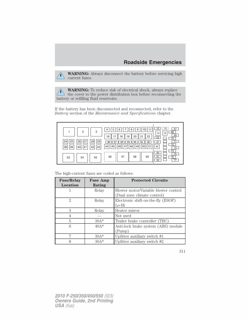
WARNING: Always disconnect the battery before servicing highcurrent fuses.
WARNING: To reduce risk of electrical shock, always replacethe cover to the power distribution box before reconnecting the
battery or refilling fluid reservoirs.
If the battery has been disconnected and reconnected, refer to theBattery section of the Maintenance and Specifications chapter.
The high-current fuses are coded as follows:
Fuse/Relay
Location
Fuse Amp
Rating
Protected Circuits
1 Relay Blower motor/Variable blower control(Dual zone climate control)
2 Relay Electronic shift-on-the-fly (ESOF)Lo-Hi
3 Relay Heater mirror4 — Not used5 30A* Trailer brake controller (TBC)6 40A* Anti-lock brake system (ABS) module
(Pump)7 30A* Upfitter auxiliary switch #18 30A* Upfitter auxiliary switch #2
Roadside Emergencies
311
2010 F-250/350/450/550 (f23)Owners Guide, 2nd PrintingUSA (fus)
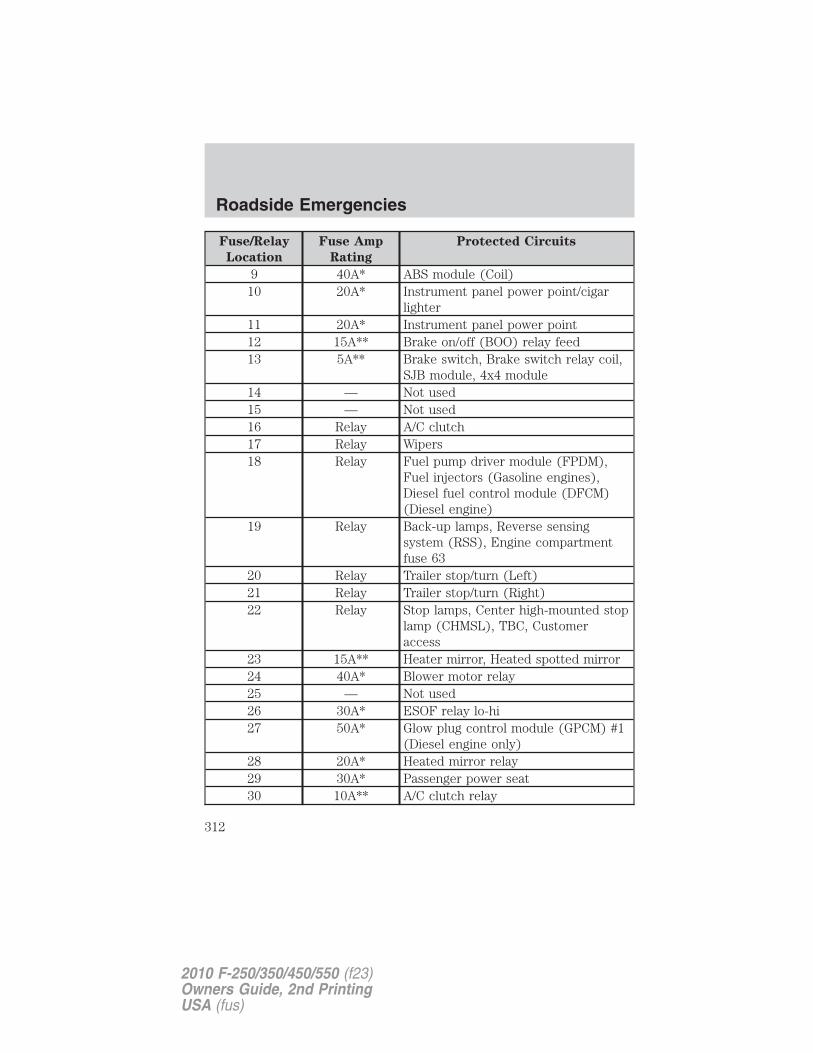
Fuse/Relay
Location
Fuse Amp
Rating
Protected Circuits
9 40A* ABS module (Coil)10 20A* Instrument panel power point/cigar
lighter11 20A* Instrument panel power point12 15A** Brake on/off (BOO) relay feed13 5A** Brake switch, Brake switch relay coil,
SJB module, 4x4 module14 — Not used15 — Not used16 Relay A/C clutch17 Relay Wipers18 Relay Fuel pump driver module (FPDM),
Fuel injectors (Gasoline engines),Diesel fuel control module (DFCM)(Diesel engine)
19 Relay Back-up lamps, Reverse sensingsystem (RSS), Engine compartmentfuse 63
20 Relay Trailer stop/turn (Left)21 Relay Trailer stop/turn (Right)22 Relay Stop lamps, Center high-mounted stop
lamp (CHMSL), TBC, Customeraccess
23 15A** Heater mirror, Heated spotted mirror24 40A* Blower motor relay25 — Not used26 30A* ESOF relay lo-hi27 50A* Glow plug control module (GPCM) #1
(Diesel engine only)28 20A* Heated mirror relay29 30A* Passenger power seat30 10A** A/C clutch relay
Roadside Emergencies
312
2010 F-250/350/450/550 (f23)Owners Guide, 2nd PrintingUSA (fus)
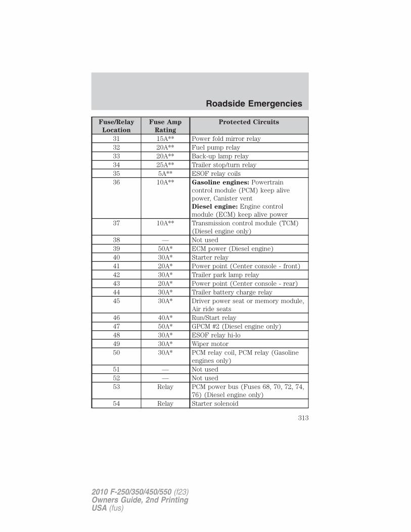
Fuse/Relay
Location
Fuse Amp
Rating
Protected Circuits
31 15A** Power fold mirror relay32 20A** Fuel pump relay33 20A** Back-up lamp relay34 25A** Trailer stop/turn relay35 5A** ESOF relay coils36 10A** Gasoline engines: Powertrain
control module (PCM) keep alivepower, Canister ventDiesel engine: Engine controlmodule (ECM) keep alive power
37 10A** Transmission control module (TCM)(Diesel engine only)
38 — Not used39 50A* ECM power (Diesel engine)40 30A* Starter relay41 20A* Power point (Center console - front)42 30A* Trailer park lamp relay43 20A* Power point (Center console - rear)44 30A* Trailer battery charge relay45 30A* Driver power seat or memory module,
Air ride seats46 40A* Run/Start relay47 50A* GPCM #2 (Diesel engine only)48 30A* ESOF relay hi-lo49 30A* Wiper motor50 30A* PCM relay coil, PCM relay (Gasoline
engines only)51 — Not used52 — Not used53 Relay PCM power bus (Fuses 68, 70, 72, 74,
76) (Diesel engine only)54 Relay Starter solenoid
Roadside Emergencies
313
2010 F-250/350/450/550 (f23)Owners Guide, 2nd PrintingUSA (fus)
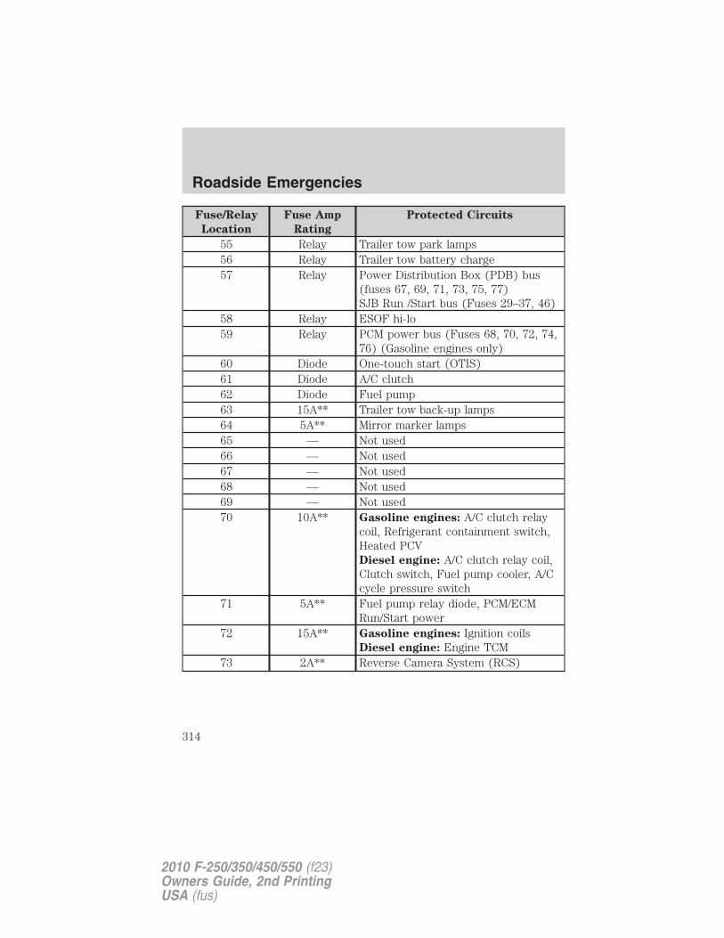
Fuse/Relay
Location
Fuse Amp
Rating
Protected Circuits
55 Relay Trailer tow park lamps56 Relay Trailer tow battery charge57 Relay Power Distribution Box (PDB) bus
(fuses 67, 69, 71, 73, 75, 77)SJB Run /Start bus (Fuses 29–37, 46)
58 Relay ESOF hi-lo59 Relay PCM power bus (Fuses 68, 70, 72, 74,
76) (Gasoline engines only)60 Diode One-touch start (OTIS)61 Diode A/C clutch62 Diode Fuel pump63 15A** Trailer tow back-up lamps64 5A** Mirror marker lamps65 — Not used66 — Not used67 — Not used68 — Not used69 — Not used70 10A** Gasoline engines: A/C clutch relay
coil, Refrigerant containment switch,Heated PCVDiesel engine: A/C clutch relay coil,Clutch switch, Fuel pump cooler, A/Ccycle pressure switch
71 5A** Fuel pump relay diode, PCM/ECMRun/Start power
72 15A** Gasoline engines: Ignition coilsDiesel engine: Engine TCM
73 2A** Reverse Camera System (RCS)
Roadside Emergencies
314
2010 F-250/350/450/550 (f23)Owners Guide, 2nd PrintingUSA (fus)
Fuse/Relay
Location
Fuse Amp
Rating
Protected Circuits
74 20A** Gasoline engines: Vehicle power(VPWR): Heated exhaust gas oxygensensor, CMS, Mass air flow sensor,Electronic vapor management valve,CMCV, Variable cam timing, IMTVDiesel engine: VPWR: Engine loads
75 5A** Back-up relay coil power76 20A** Gasoline engines: VPWR: PCM
Diesel engine: VPWR: ECM77 10A** ABS module logic
* Cartridge fuses ** Mini fuses
CHANGING A FLAT TIREIf you get a flat tire while driving:
• do not brake heavily.
• gradually decrease the vehicle’s speed.
• hold the steering wheel firmly.
• slowly move to a safe place on the side of the road.
Your vehicle may be equipped with a conventional spare tire that isdifferent in one or more of the following: type, brand, size, speed ratingand tread design. If this is the case, this dissimilar spare tire is still ratedfor your vehicle loads (GAWR and GVWR). Temporary spare tires are notequipped with Tire Pressure Monitor System (TPMS) sensors if thesystem is present.
WARNING: The use of tire sealant may damage your TirePressure Monitoring System (if equipped) and should not be
used.
WARNING: If your vehicle is equipped with a Tire PressureMonitoring System, refer to Tire Pressure Monitoring System
(TPMS) in the Tires, Wheels and Loading chapter for moreinformation. If the tire pressure monitor sensor becomes damaged, itwill no longer function.
Roadside Emergencies
315
2010 F-250/350/450/550 (f23)Owners Guide, 2nd PrintingUSA (fus)
Dissimilar spare tire/wheel information
WARNING: Failure to follow these guidelines could result in anincreased risk of loss of vehicle control, injury or death.
If you have a dissimilar spare tire/wheel, then it is intended fortemporary use only. This means that if you need to use it, you shouldreplace it as soon as possible with a road tire/wheel that is the same sizeand type as the road tires and wheels that were originally provided byFord. If the dissimilar spare tire or wheel is damaged, it should bereplaced rather than repaired.A dissimilar spare tire/wheel is defined as a spare tire and/or wheel thatis different in brand, size or appearance from the road tires and wheelsand can be one of three types:1. T-type mini-spare: This spare tire begins with the letter “T” for tiresize and may have “Temporary Use Only” molded in the sidewall2. Full-size dissimilar spare with label on wheel: This spare tire hasa label on the wheel that states: “THIS TIRE AND WHEEL FORTEMPORARY USE ONLY”When driving with one of the dissimilar spare tires listed above, do not:
• Exceed 50 mph (80 km/h)• Load the vehicle beyond maximum vehicle load rating listed on the
Safety Compliance Label• Use snow chains on the end of the vehicle with the dissimilar spare
tire• Use more than one dissimilar spare tire at a time• Use commercial car washing equipment• Try to repair the dissimilar spare tireUse of one of the dissimilar spare tires listed above at any one wheellocation can lead to impairment of the following:• Handling, stability and braking performance• Comfort and noise• Ground clearance and parking at curbs• Winter weather driving capability• Wet weather driving capabilityIt is not recommended that the vehicle be operated in 4WD modes witha temporary emergency spare tire. If 4WD operation is necessary, do notoperate above speeds of 10 mph (16 km/h) or for distances above50 miles (80 km).
Roadside Emergencies
316
2010 F-250/350/450/550 (f23)Owners Guide, 2nd PrintingUSA (fus)
3. Full-size dissimilar spare without label on wheel
When driving with the full-size dissimilar spare tire/wheel, do not:
• Exceed 70 mph (113 km/h)
• Use more than one dissimilar spare tire/wheel at a time
• Use commercial car washing equipment
• Use snow chains on the end of the vehicle with the dissimilar sparetire/wheel
The usage of a full-size dissimilar spare tire/wheel can lead toimpairment of the following:
• Handling, stability and braking performance
• Comfort and noise
• Ground clearance and parking at curbs
• Winter weather driving capability
• Wet weather driving capability
• All-Wheel driving capability (if applicable)
• Load leveling adjustment (if applicable)
When driving with the full-size dissimilar spare tire/wheel additionalcaution should be given to:
• Towing a trailer
• Driving vehicles equipped with a camper body
• Driving vehicles with a load on the cargo rack
Drive cautiously when using a full-size dissimilar spare tire/wheel andseek service as soon as possible.
Spare tire information
Note: If your vehicle is equipped the tire pressure monitoring system(TPMS), the system indicator light will illuminate when the spare is inuse. To restore the full functionality of the TPMS system, all road wheelsequipped with the tire pressure monitoring sensors must be mounted onthe vehicle.
If your vehicle is equipped with TPMS, have a flat tire serviced by anauthorized dealer in order to prevent damage to the TPMS sensor; referto Tire Pressure Monitoring System (TPMS) in the Tires, Wheel andLoading chapter. Replace the spare tire with the road tire as soon aspossible.
Roadside Emergencies
317
2010 F-250/350/450/550 (f23)Owners Guide, 2nd PrintingUSA (fus)
Stopping and securing the vehicle
WARNING: To help prevent the vehicle from moving when youchange a tire, be sure the parking brake is set, then block (in
both directions) the wheel that is diagonally opposite to the tire beingchanged.
Refer to the instruction sheet (located in the glove box) for detailed tirechange instructions.
Park on a level surface, activatehazard flashers and set the parkingbrake.
• Automatic transmission: Placegearshift lever in P (Park).
• Manual transmission: Placegearshift lever in R (Reverse).
• Electronic Shift-On-the-Fly(ESOF) 4x4: Place transfer casein 4x4 HIGH or 4x4 LOW beforeturning off the engine.
• Manual shift transfer case 4x4: Place transfer case in 4H or 4L.
Location of the spare tire and tools
If your vehicle is equipped with a spare tire, jack and associated tools,refer to the following table for their locations:
Tool Location
Spare tire (pick-up trucks only) Under the vehicle, just forward ofthe rear bumper
Jack Regular cab and Crew Cab:Fastened to floor pan behindrearmost seat on passenger sideSuperCab: Under rear bench seaton passenger side
Roadside Emergencies
318
2010 F-250/350/450/550 (f23)Owners Guide, 2nd PrintingUSA (fus)
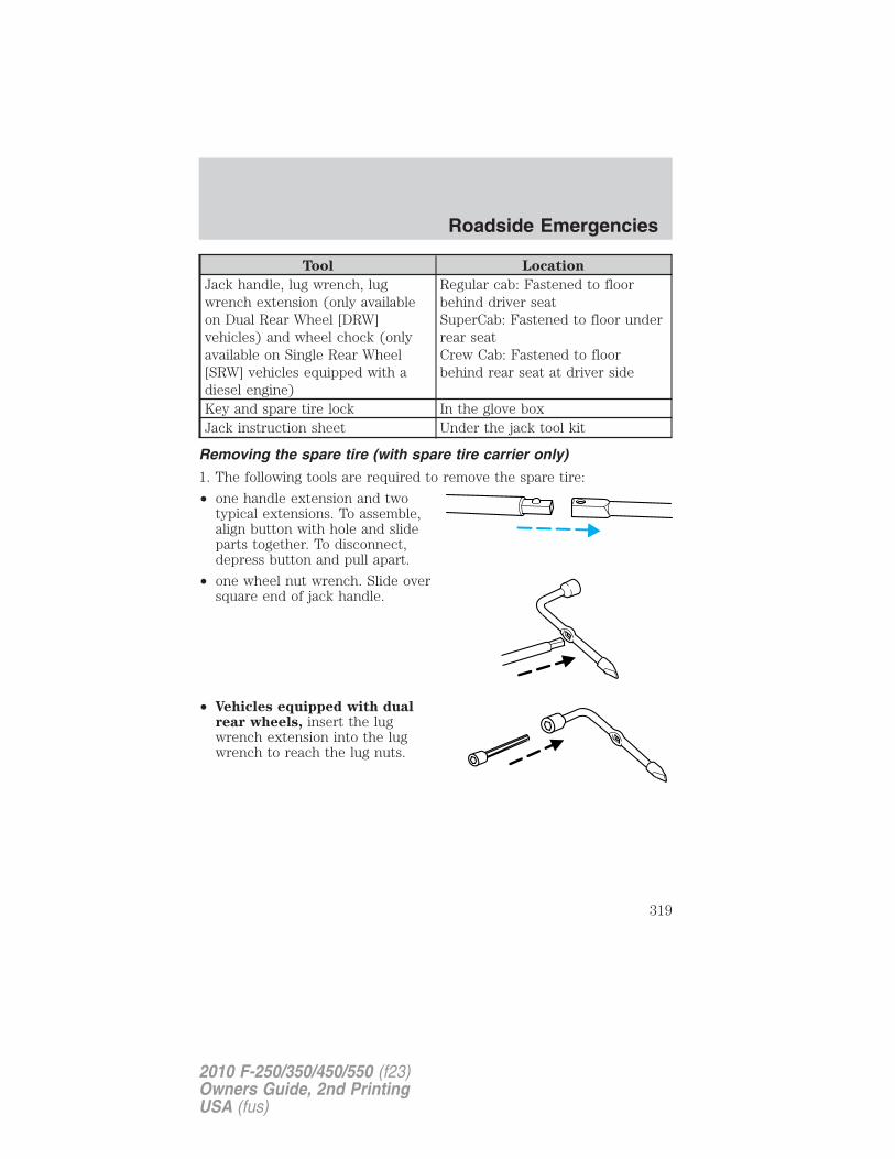
Tool Location
Jack handle, lug wrench, lugwrench extension (only availableon Dual Rear Wheel [DRW]vehicles) and wheel chock (onlyavailable on Single Rear Wheel[SRW] vehicles equipped with adiesel engine)
Regular cab: Fastened to floorbehind driver seatSuperCab: Fastened to floor underrear seatCrew Cab: Fastened to floorbehind rear seat at driver side
Key and spare tire lock In the glove boxJack instruction sheet Under the jack tool kit
Removing the spare tire (with spare tire carrier only)
1. The following tools are required to remove the spare tire:
• one handle extension and twotypical extensions. To assemble,align button with hole and slideparts together. To disconnect,depress button and pull apart.
• one wheel nut wrench. Slide oversquare end of jack handle.
• Vehicles equipped with dualrear wheels, insert the lugwrench extension into the lugwrench to reach the lug nuts.
Roadside Emergencies
319
2010 F-250/350/450/550 (f23)Owners Guide, 2nd PrintingUSA (fus)
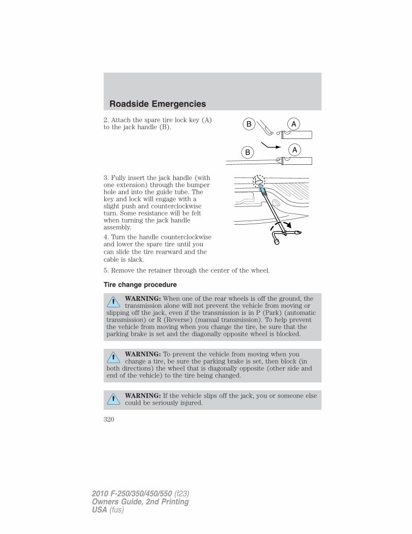
2. Attach the spare tire lock key (A)to the jack handle (B).
3. Fully insert the jack handle (withone extension) through the bumperhole and into the guide tube. Thekey and lock will engage with aslight push and counterclockwiseturn. Some resistance will be feltwhen turning the jack handleassembly.
4. Turn the handle counterclockwiseand lower the spare tire until youcan slide the tire rearward and thecable is slack.
5. Remove the retainer through the center of the wheel.
Tire change procedure
WARNING: When one of the rear wheels is off the ground, thetransmission alone will not prevent the vehicle from moving or
slipping off the jack, even if the transmission is in P (Park) (automatictransmission) or R (Reverse) (manual transmission). To help preventthe vehicle from moving when you change the tire, be sure that theparking brake is set and the diagonally opposite wheel is blocked.
WARNING: To prevent the vehicle from moving when youchange a tire, be sure the parking brake is set, then block (in
both directions) the wheel that is diagonally opposite (other side andend of the vehicle) to the tire being changed.
WARNING: If the vehicle slips off the jack, you or someone elsecould be seriously injured.
Roadside Emergencies
320
2010 F-250/350/450/550 (f23)Owners Guide, 2nd PrintingUSA (fus)
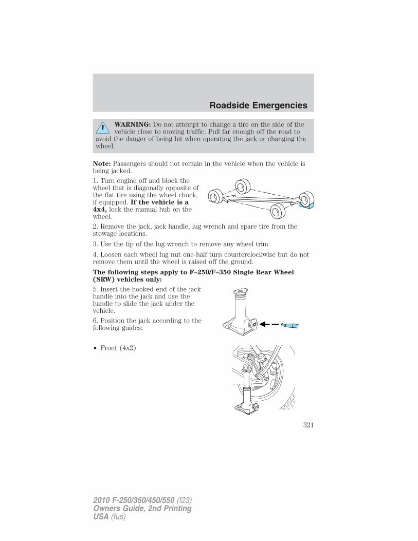
WARNING: Do not attempt to change a tire on the side of thevehicle close to moving traffic. Pull far enough off the road to
avoid the danger of being hit when operating the jack or changing thewheel.
Note: Passengers should not remain in the vehicle when the vehicle isbeing jacked.
1. Turn engine off and block thewheel that is diagonally opposite ofthe flat tire using the wheel chock,if equipped. If the vehicle is a4x4, lock the manual hub on thewheel.
2. Remove the jack, jack handle, lug wrench and spare tire from thestowage locations.
3. Use the tip of the lug wrench to remove any wheel trim.
4. Loosen each wheel lug nut one-half turn counterclockwise but do notremove them until the wheel is raised off the ground.
The following steps apply to F–250/F–350 Single Rear Wheel(SRW) vehicles only:
5. Insert the hooked end of the jackhandle into the jack and use thehandle to slide the jack under thevehicle.
6. Position the jack according to thefollowing guides:
• Front (4x2)
Roadside Emergencies
321
2010 F-250/350/450/550 (f23)Owners Guide, 2nd PrintingUSA (fus)
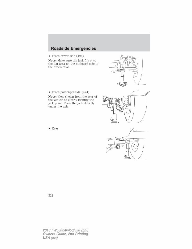
• Front driver side (4x4)
Note: Make sure the jack fits ontothe flat area on the outboard side ofthe differential.
• Front passenger side (4x4)
Note: View shown from the rear ofthe vehicle to clearly identify thejack point. Place the jack directlyunder the axle.
• Rear
Roadside Emergencies
322
2010 F-250/350/450/550 (f23)Owners Guide, 2nd PrintingUSA (fus)
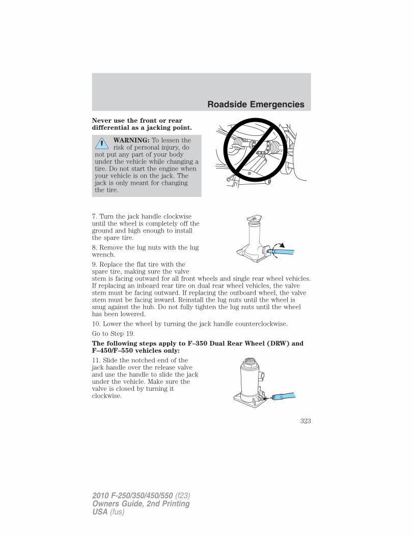
Never use the front or reardifferential as a jacking point.
WARNING: To lessen therisk of personal injury, do
not put any part of your bodyunder the vehicle while changing atire. Do not start the engine whenyour vehicle is on the jack. Thejack is only meant for changingthe tire.
7. Turn the jack handle clockwiseuntil the wheel is completely off theground and high enough to installthe spare tire.
8. Remove the lug nuts with the lugwrench.
9. Replace the flat tire with thespare tire, making sure the valvestem is facing outward for all front wheels and single rear wheel vehicles.If replacing an inboard rear tire on dual rear wheel vehicles, the valvestem must be facing outward. If replacing the outboard wheel, the valvestem must be facing inward. Reinstall the lug nuts until the wheel issnug against the hub. Do not fully tighten the lug nuts until the wheelhas been lowered.
10. Lower the wheel by turning the jack handle counterclockwise.
Go to Step 19.
The following steps apply to F–350 Dual Rear Wheel (DRW) andF–450/F–550 vehicles only:
11. Slide the notched end of thejack handle over the release valveand use the handle to slide the jackunder the vehicle. Make sure thevalve is closed by turning itclockwise.
Roadside Emergencies
323
2010 F-250/350/450/550 (f23)Owners Guide, 2nd PrintingUSA (fus)
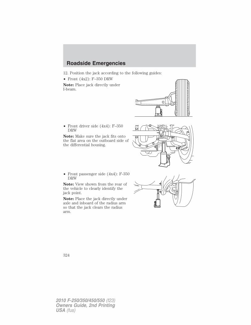
12. Position the jack according to the following guides:
• Front (4x2): F–350 DRW
Note: Place jack directly underI-beam.
• Front driver side (4x4): F–350DRW
Note: Make sure the jack fits ontothe flat area on the outboard side ofthe differential housing.
• Front passenger side (4x4): F-350DRW
Note: View shown from the rear ofthe vehicle to clearly identify thejack point.
Note: Place the jack directly underaxle and inboard of the radius armso that the jack clears the radiusarm.
Roadside Emergencies
324
2010 F-250/350/450/550 (f23)Owners Guide, 2nd PrintingUSA (fus)
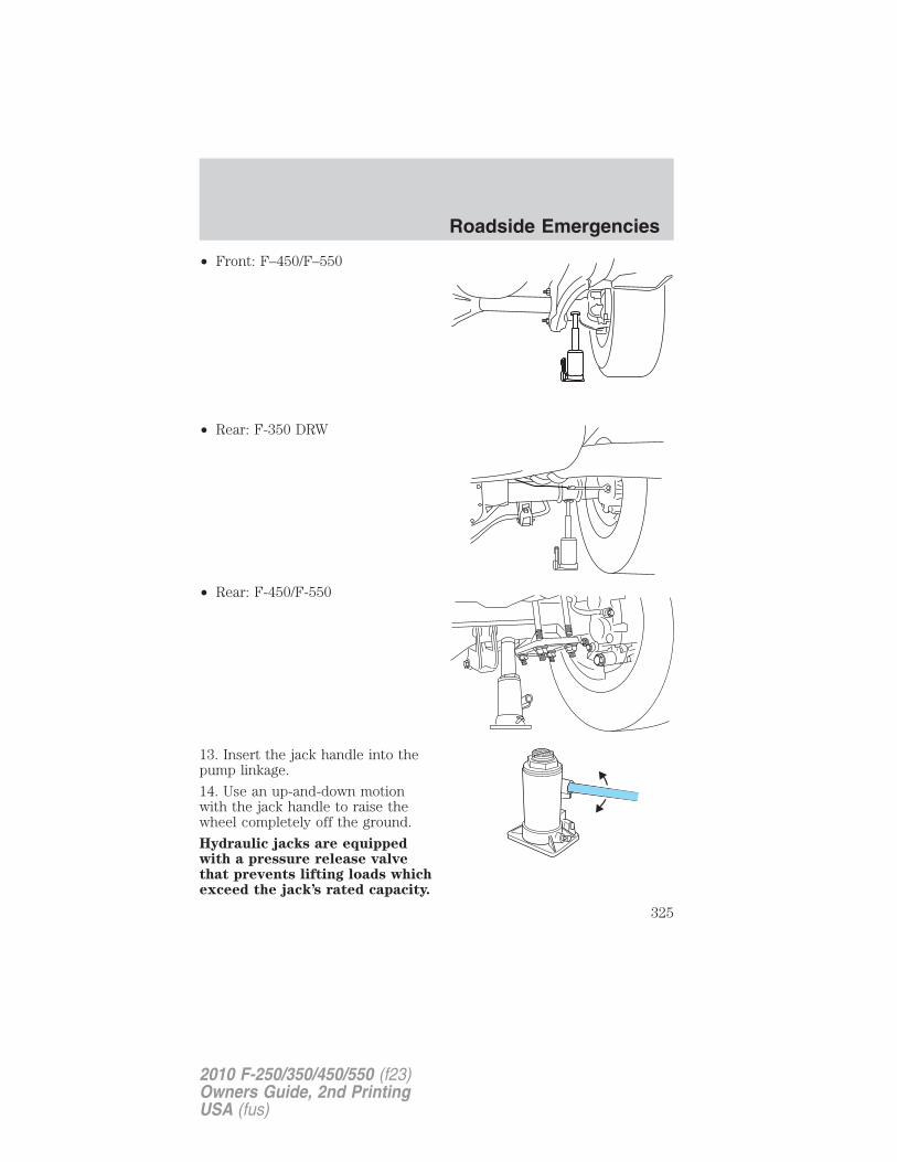
• Front: F–450/F–550
• Rear: F-350 DRW
• Rear: F-450/F-550
13. Insert the jack handle into thepump linkage.
14. Use an up-and-down motionwith the jack handle to raise thewheel completely off the ground.
Hydraulic jacks are equippedwith a pressure release valvethat prevents lifting loads whichexceed the jack’s rated capacity.
Roadside Emergencies
325
2010 F-250/350/450/550 (f23)Owners Guide, 2nd PrintingUSA (fus)
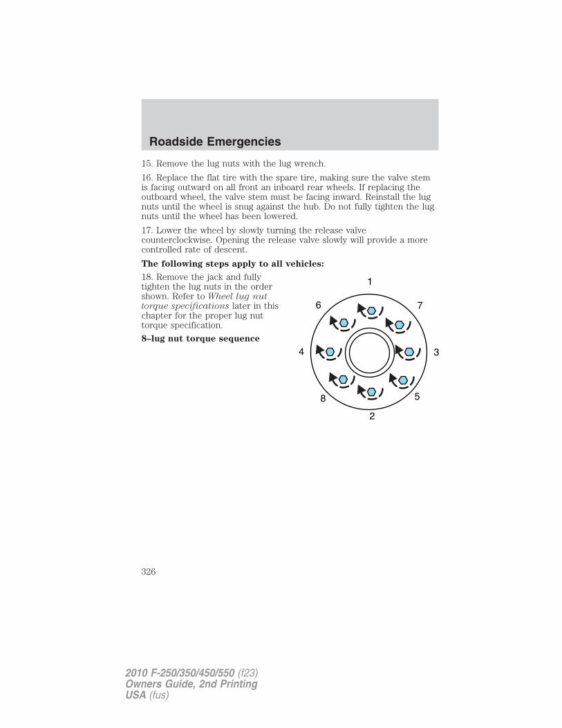
15. Remove the lug nuts with the lug wrench.
16. Replace the flat tire with the spare tire, making sure the valve stemis facing outward on all front an inboard rear wheels. If replacing theoutboard wheel, the valve stem must be facing inward. Reinstall the lugnuts until the wheel is snug against the hub. Do not fully tighten the lugnuts until the wheel has been lowered.
17. Lower the wheel by slowly turning the release valvecounterclockwise. Opening the release valve slowly will provide a morecontrolled rate of descent.
The following steps apply to all vehicles:
18. Remove the jack and fullytighten the lug nuts in the ordershown. Refer to Wheel lug nuttorque specifications later in thischapter for the proper lug nuttorque specification.
8–lug nut torque sequence
Roadside Emergencies
326
2010 F-250/350/450/550 (f23)Owners Guide, 2nd PrintingUSA (fus)
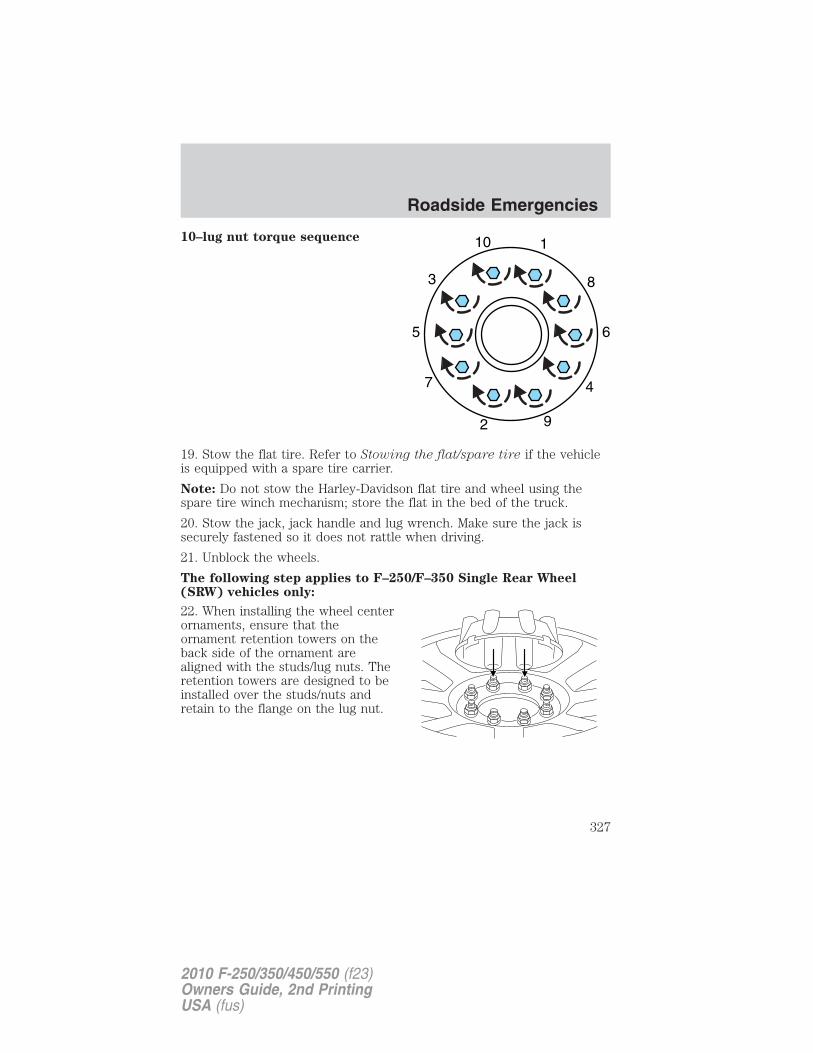
10–lug nut torque sequence
19. Stow the flat tire. Refer to Stowing the flat/spare tire if the vehicleis equipped with a spare tire carrier.
Note: Do not stow the Harley-Davidson flat tire and wheel using thespare tire winch mechanism; store the flat in the bed of the truck.
20. Stow the jack, jack handle and lug wrench. Make sure the jack issecurely fastened so it does not rattle when driving.
21. Unblock the wheels.
The following step applies to F–250/F–350 Single Rear Wheel(SRW) vehicles only:
22. When installing the wheel centerornaments, ensure that theornament retention towers on theback side of the ornament arealigned with the studs/lug nuts. Theretention towers are designed to beinstalled over the studs/nuts andretain to the flange on the lug nut.
Roadside Emergencies
327
2010 F-250/350/450/550 (f23)Owners Guide, 2nd PrintingUSA (fus)
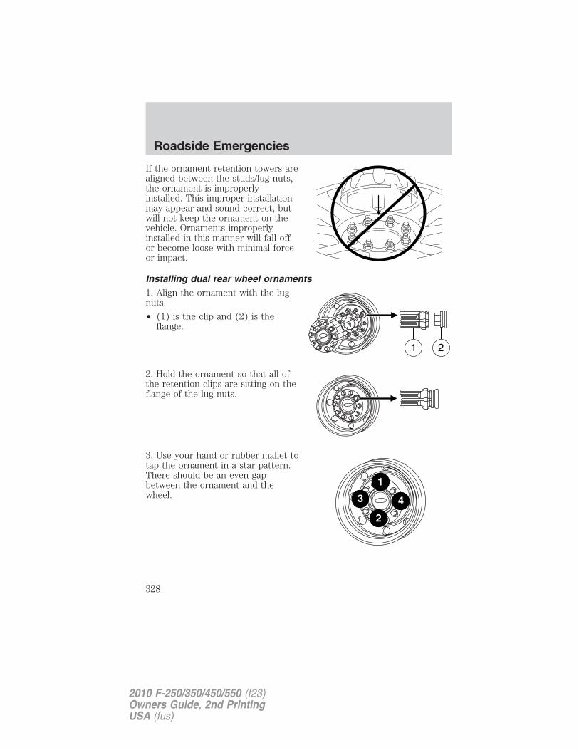
If the ornament retention towers arealigned between the studs/lug nuts,the ornament is improperlyinstalled. This improper installationmay appear and sound correct, butwill not keep the ornament on thevehicle. Ornaments improperlyinstalled in this manner will fall offor become loose with minimal forceor impact.
Installing dual rear wheel ornaments1. Align the ornament with the lugnuts.
• (1) is the clip and (2) is theflange.
2. Hold the ornament so that all ofthe retention clips are sitting on theflange of the lug nuts.
3. Use your hand or rubber mallet totap the ornament in a star pattern.There should be an even gapbetween the ornament and thewheel.
1 2
Roadside Emergencies
328
2010 F-250/350/450/550 (f23)Owners Guide, 2nd PrintingUSA (fus)

4. Be sure to install all the clips on the nuts over the flanges so thatthere is an even gap all around and the retention clips are fully seated.
Stowing the flat/spare tireNote: Failure to follow spare tire stowage instructions may result infailure of cable or loss of spare tire.1. Lay the tire on the ground with the valve stem facing in the directionspecified on the Tire Changing Instructions located in the glove box.2. Slide the wheel partially under the vehicle and install the retainerthrough the wheel center. Pull on the cable to align the components atthe end of the cable.3. Turn the jack handle clockwise until the tire is raised to its stowedposition underneath the vehicle. The effort to turn the jack handleincreases significantly and the spare tire carrier ratchets or slips whenthe tire is raised to the maximum tightness. Tighten to the best of yourability, to the point where the ratchet/slip occurs, if possible. The sparetire carrier will not allow you to overtighten. If the spare tire carrierratchets or slips with little effort, take the vehicle to your authorizeddealer for assistance at your earliest convenience.
4. Check that the tire lies flat against the frame and is properlytightened. Try to push or pull, then turn the tire to be sure it will notmove. Loosen and retighten, if necessary. Failure to properly stow thespare tire may result in failure of the winch cable and loss of the tire.
Roadside Emergencies
329
2010 F-250/350/450/550 (f23)Owners Guide, 2nd PrintingUSA (fus)
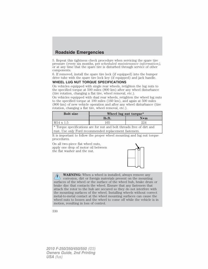
5. Repeat this tightness check procedure when servicing the spare tirepressure (every six months, per scheduled maintenance information),or at any time that the spare tire is disturbed through service of othercomponents.6. If removed, install the spare tire lock (if equipped) into the bumperdrive tube with the spare tire lock key (if equipped) and jack handle.WHEEL LUG NUT TORQUE SPECIFICATIONSOn vehicles equipped with single rear wheels, retighten the lug nuts tothe specified torque at 500 miles (800 km) after any wheel disturbance(tire rotation, changing a flat tire, wheel removal, etc.).On vehicles equipped with dual rear wheels, retighten the wheel lug nutsto the specified torque at 100 miles (160 km), and again at 500 miles(800 km) of new vehicle operation and after any wheel disturbance (tirerotation, changing a flat tire, wheel removal, etc.).
Bolt size Wheel lug nut torque*
lb.ft. N•m
M14 x 1.5 165 224* Torque specifications are for nut and bolt threads free of dirt andrust. Use only Ford recommended replacement fasteners.
It is important to follow the proper wheel mounting and lug nut torqueprocedures.
On all two-piece flat wheel nuts,apply one drop of motor oil betweenthe flat washer and the nut.
WARNING: When a wheel is installed, always remove anycorrosion, dirt or foreign materials present on the mounting
surfaces of the wheel or the surface of the wheel hub, brake drum orbrake disc that contacts the wheel. Ensure that any fasteners thatattach the rotor to the hub are secured so they do not interfere withthe mounting surfaces of the wheel. Installing wheels without correctmetal-to-metal contact at the wheel mounting surfaces can cause thewheel nuts to loosen and the wheel to come off while the vehicle is inmotion, resulting in loss of control.
Roadside Emergencies
330
2010 F-250/350/450/550 (f23)Owners Guide, 2nd PrintingUSA (fus)
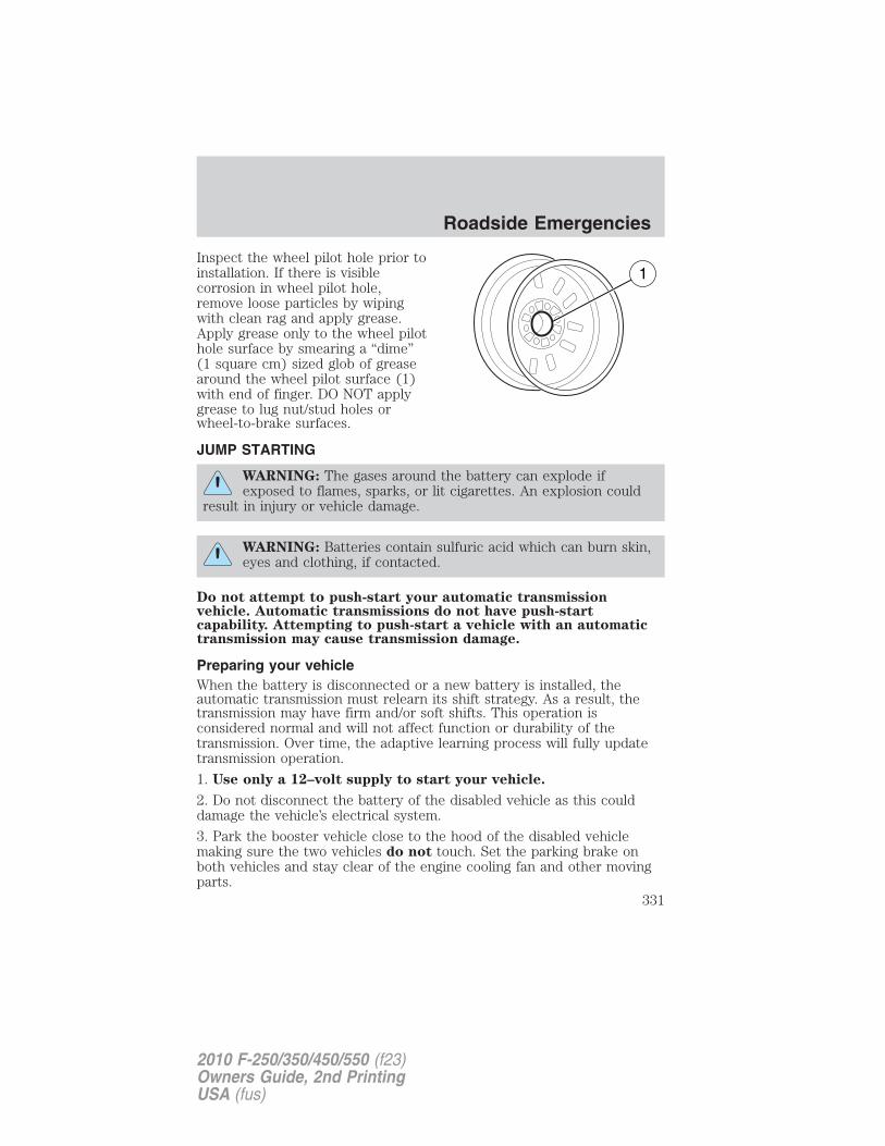
Inspect the wheel pilot hole prior toinstallation. If there is visiblecorrosion in wheel pilot hole,remove loose particles by wipingwith clean rag and apply grease.Apply grease only to the wheel pilothole surface by smearing a “dime”(1 square cm) sized glob of greasearound the wheel pilot surface (1)with end of finger. DO NOT applygrease to lug nut/stud holes orwheel-to-brake surfaces.
JUMP STARTING
WARNING: The gases around the battery can explode ifexposed to flames, sparks, or lit cigarettes. An explosion could
result in injury or vehicle damage.
WARNING: Batteries contain sulfuric acid which can burn skin,eyes and clothing, if contacted.
Do not attempt to push-start your automatic transmissionvehicle. Automatic transmissions do not have push-startcapability. Attempting to push-start a vehicle with an automatictransmission may cause transmission damage.
Preparing your vehicleWhen the battery is disconnected or a new battery is installed, theautomatic transmission must relearn its shift strategy. As a result, thetransmission may have firm and/or soft shifts. This operation isconsidered normal and will not affect function or durability of thetransmission. Over time, the adaptive learning process will fully updatetransmission operation.
1. Use only a 12–volt supply to start your vehicle.
2. Do not disconnect the battery of the disabled vehicle as this coulddamage the vehicle’s electrical system.
3. Park the booster vehicle close to the hood of the disabled vehiclemaking sure the two vehicles do not touch. Set the parking brake onboth vehicles and stay clear of the engine cooling fan and other movingparts.
Roadside Emergencies
331
2010 F-250/350/450/550 (f23)Owners Guide, 2nd PrintingUSA (fus)
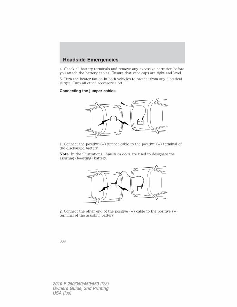
4. Check all battery terminals and remove any excessive corrosion beforeyou attach the battery cables. Ensure that vent caps are tight and level.
5. Turn the heater fan on in both vehicles to protect from any electricalsurges. Turn all other accessories off.
Connecting the jumper cables
1. Connect the positive (+) jumper cable to the positive (+) terminal ofthe discharged battery.
Note: In the illustrations, lightning bolts are used to designate theassisting (boosting) battery.
2. Connect the other end of the positive (+) cable to the positive (+)terminal of the assisting battery.
+–
+–
+–+–
Roadside Emergencies
332
2010 F-250/350/450/550 (f23)Owners Guide, 2nd PrintingUSA (fus)
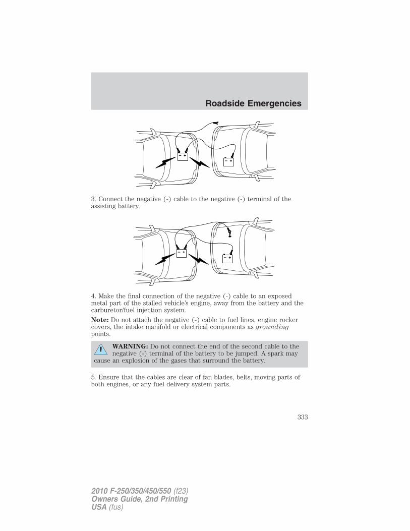
3. Connect the negative (-) cable to the negative (-) terminal of theassisting battery.
4. Make the final connection of the negative (-) cable to an exposedmetal part of the stalled vehicle’s engine, away from the battery and thecarburetor/fuel injection system.
Note: Do not attach the negative (-) cable to fuel lines, engine rockercovers, the intake manifold or electrical components as groundingpoints.
WARNING: Do not connect the end of the second cable to thenegative (-) terminal of the battery to be jumped. A spark may
cause an explosion of the gases that surround the battery.
5. Ensure that the cables are clear of fan blades, belts, moving parts ofboth engines, or any fuel delivery system parts.
+–
+–
+–
+–
Roadside Emergencies
333
2010 F-250/350/450/550 (f23)Owners Guide, 2nd PrintingUSA (fus)
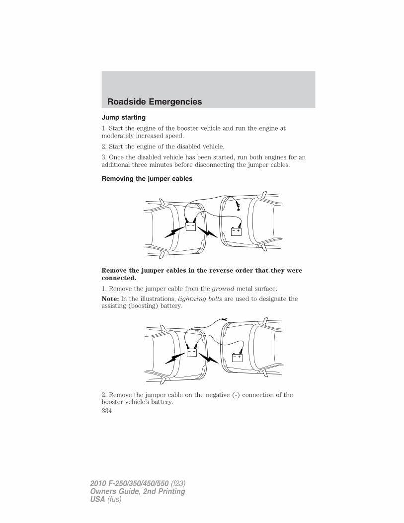
Jump starting
1. Start the engine of the booster vehicle and run the engine atmoderately increased speed.
2. Start the engine of the disabled vehicle.
3. Once the disabled vehicle has been started, run both engines for anadditional three minutes before disconnecting the jumper cables.
Removing the jumper cables
Remove the jumper cables in the reverse order that they were
connected.
1. Remove the jumper cable from the ground metal surface.
Note: In the illustrations, lightning bolts are used to designate theassisting (boosting) battery.
2. Remove the jumper cable on the negative (-) connection of thebooster vehicle’s battery.
+–
+–
+–
+–
Roadside Emergencies
334
2010 F-250/350/450/550 (f23)Owners Guide, 2nd PrintingUSA (fus)
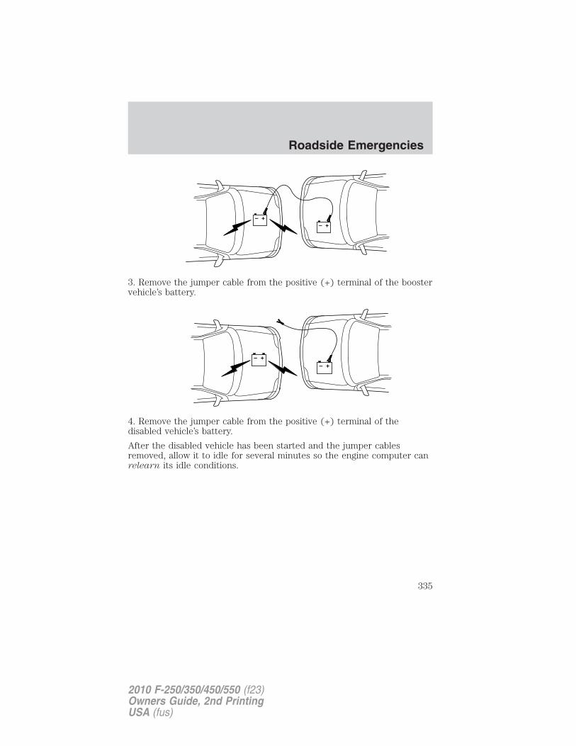
3. Remove the jumper cable from the positive (+) terminal of the boostervehicle’s battery.
4. Remove the jumper cable from the positive (+) terminal of thedisabled vehicle’s battery.
After the disabled vehicle has been started and the jumper cablesremoved, allow it to idle for several minutes so the engine computer canrelearn its idle conditions.
+–
+–
+–
+–
Roadside Emergencies
335
2010 F-250/350/450/550 (f23)Owners Guide, 2nd PrintingUSA (fus)
WRECKER TOWING
If you need to have your vehicle towed, contact a professional towingservice or, if you are a member of a roadside assistance program, yourroadside assistance service provider.
It is recommended that the vehicle be towed with a wheel lift or flatbedequipment. Do not tow with a slingbelt. Ford Motor Company has notapproved a slingbelt towing procedure.
On 4x2 vehicles, it is acceptable to tow the vehicle with the front wheelson the ground and the rear wheels off the ground using a wheel lift
On 4x4 vehicles, it is recommended that your vehicle be towed usingflatbed equipment with all the wheels off the ground. However, a wheellift may be used to lift the rear of the vehicle so long as, depending onvehicle configurations, the following preparations are met:
• On Electronic Shift-On-the-Fly (ESOF) vehicles, the 4x4 control isturned to the 2WD position prior to towing.
• On manual-shift transfer case vehicles, the front wheel hub locks arein the FREE position prior to towing.
Roadside Emergencies
336
2010 F-250/350/450/550 (f23)Owners Guide, 2nd PrintingUSA (fus)
Note: Towing an ESOF 4x4 vehicle with the front wheels on the groundwithout disengaging the front hubs may cause damage to the automatictransmission.
Note: Towing a 4x2 or an ESOF 4x4 vehicle with the rear wheels on theground for more than 50 miles (80 km) and/or in excess of 35 mph(56 km/h) may cause damage to the automatic transmission.
Note: On Dual Rear Wheel (DRW) vehicles, an outer rear wheel must beremoved prior to using a wheel lift wrecker.
Ford Motor Company produces a towing manual for all authorized towtruck operators. Have your tow truck operator refer to this manual forproper hook-up and towing procedures for your vehicle.
If the vehicle is towed by other means or incorrectly, vehicledamage may occur.
Emergency towingIn case of a roadside emergency with a disabled vehicle (without accessto wheel dollies, car hauling trailer, or flatbed transport vehicle) yourvehicle (regardless of transmission powertrain configuration) can be flattowed (all wheels on the ground) under the following conditions:
• Vehicle is facing forward so that it is being towed in a forwarddirection.
• Place the transmission in N (Neutral). Refer to Brake-shift interlockin the Driving chapter for specific instructions if you cannot move thegear shift lever into N (Neutral).
• Maximum speed is not to exceed 35 mph (56 km/h).
• Maximum distance is 50 miles (80 km).
Roadside Emergencies
337
2010 F-250/350/450/550 (f23)Owners Guide, 2nd PrintingUSA (fus)
GETTING THE SERVICES YOU NEEDWarranty repairs to your vehicle must be performed by an authorizedFord, Lincoln, or Mercury dealer. While any authorized dealer handlingyour vehicle line will provide warranty service, we recommend youreturn to your selling authorized dealer who wants to ensure yourcontinued satisfaction.
Please note that certain warranty repairs require special training and/orequipment, so not all authorized dealers are authorized to perform allwarranty repairs. This means that, depending on the warranty repairneeded, you may have to take your vehicle to another authorized dealer.
A reasonable time must be allowed to perform a repair after taking yourvehicle to the authorized dealer. Repairs will be made using Ford orMotorcraft� parts, or remanufactured or other parts that are authorizedby Ford.
Away from homeIf you are away from home when your vehicle needs service, contact theFord Customer Relationship Center or use the online resources listedbelow to find the nearest authorized dealer.
In the United States:
Mailing addressFord Motor CompanyCustomer Relationship CenterP.O. Box 6248Dearborn, MI 48121
Telephone1-800-392-3673 (FORD)(TDD for the hearing impaired: 1-800-232-5952)
OnlineAdditional information and resources are available online atwww.genuineservice.com.
• U.S. dealer locator by Dealer Name, City/State, or Zip Code
• Owner Guides
• Maintenance Schedules
• Recalls
• Ford Extended Service Plans
• Ford Genuine Accessories
Customer Assistance
338
2010 F-250/350/450/550 (f23)Owners Guide, 2nd PrintingUSA (fus)
• Service specials and promotions.In Canada:Mailing address (Ford vehicles)Customer Relationship CentreFord Motor Company of Canada, LimitedP.O. Box 2000Oakville, Ontario L6J 5E4Telephone1-800-565-3673 (FORD)Onlinewww.ford.caMailing address (Lincoln vehicles)Lincoln CentreFord Motor Company of Canada, LimitedP.O. Box 2000Oakville, Ontario L6J 5E4Telephone1-800-387-9333Onlinewww.lincolncanada.com
Additional assistanceIf you have questions or concerns, or are unsatisfied with the service youare receiving, follow these steps:1. Contact your Sales Representative or Service Advisor at yourselling/servicing authorized dealer.2. If your inquiry or concern remains unresolved, contact the SalesManager, Service Manager or Customer Relations Manager.3. If you require assistance or clarification on Ford Motor Companypolicies, please contact the Ford Customer Relationship CenterIn order to help you serve you better, please have the followinginformation available when contacting a Customer Relationship Center:• Vehicle Identification Number (VIN)• Your telephone number (home and business)• The name of the authorized dealer and city where located• The vehicle’s current odometer reading
In some states, you must directly notify Ford in writing before pursuingremedies under your state’s warranty laws. Ford is also allowed a finalrepair attempt in some states.
Customer Assistance
339
2010 F-250/350/450/550 (f23)Owners Guide, 2nd PrintingUSA (fus)
In the United States, a warranty dispute must be submitted to the BBBAUTO LINE before taking action under the Magnuson-Moss WarrantyAct, or to the extent allowed by state law, before pursuing replacementor repurchase remedies provided by certain state laws. This disputehandling procedure is not required prior to enforcing state created rightsor other rights which are independent of the Magnuson-Moss WarrantyAct or state replacement or repurchase laws.
IN CALIFORNIA (U.S. ONLY)California Civil Code Section 1793.2(d) requires that, if a manufactureror its representative is unable to repair a motor vehicle to conform to thevehicle’s applicable express warranty after a reasonable number ofattempts, the manufacturer shall be required to either replace thevehicle with one substantially identical or repurchase the vehicle andreimburse the buyer in an amount equal to the actual price paid orpayable by the consumer (less a reasonable allowance for consumeruse). The consumer has the right to choose whether to receive a refundor replacement vehicle.California Civil Code Section 1793.22(b) presumes that the manufacturerhas had a reasonable number of attempts to conform the vehicle to itsapplicable express warranties if, within the first 18 months of ownershipof a new vehicle or the first 18,000 miles (29,000 km), whichever occursfirst:1. Two or more repair attempts are made on the same non-conformitylikely to cause death or serious bodily injury OR2. Four or more repair attempts are made on the same nonconformity (adefect or condition that substantially impairs the use, value or safety ofthe vehicle) OR3. The vehicle is out of service for repair of nonconformities for a total ofmore than 30 calendar days (not necessarily all at one time)In the case of 1 or 2 above, the consumer must also notify themanufacturer of the need for the repair of the nonconformity at thefollowing address:
Ford Motor Company16800 Executive Plaza DriveMail Drop 3NE-BDearborn, MI 48126
THE BETTER BUSINESS BUREAU (BBB) AUTO LINE PROGRAM(U.S. ONLY)Your satisfaction is important to Ford Motor Company and to your dealer.If a warranty concern has not been resolved using the three-step
Customer Assistance
340
2010 F-250/350/450/550 (f23)Owners Guide, 2nd PrintingUSA (fus)
procedure outlined on the first page of the Customer Assistance section,you may be eligible to participate in the BBB AUTO LINE program.The BBB AUTO LINE program consists of two parts – mediation andarbitration. During mediation, a representative of the BBB will contactboth you and Ford Motor Company to explore options for settlement ofthe claim. If an agreement is not reached during mediation and yourclaim is eligible, you may participate in the arbitration process. Anarbitration hearing will be scheduled so that you can present your casein an informal setting before an impartial person. The arbitrator willconsider the testimony provided and make a decision after the hearing.You are not bound by the decision, but should you choose to accept theBBB AUTO LINE decision, Ford must abide by the accepted decision aswell. Disputes submitted to the BBB AUTO LINE program are usuallydecided within forty days after you file your claim with the BBB.BBB AUTO LINE Application: Using the information provided below,please call or write to request a program application. You will be askedfor your name and address, general information about your new vehicle,information about your warranty concerns, and any steps you havealready taken to try to resolve them. A Customer Claim Form will bemailed that will need to be completed, signed and returned to the BBBalong with proof of ownership. Upon receipt, the BBB will review theclaim for eligibility under the Program Summary Guidelines.
You can get more information by calling BBB AUTO LINE at1-800-955-5100, or writing to:
BBB AUTO LINE4200 Wilson Boulevard, Suite 800Arlington, Virginia 22203–1833
BBB AUTO LINE applications can also be requested by calling the FordMotor Company Customer Relationship Center at 1-800-392-3673.
Note: Ford Motor Company reserves the right to change eligibilitylimitations, modify procedures, or to discontinue this process at any timewithout notice and without obligation.
UTILIZING THE MEDIATION/ARBITRATION PROGRAM(CANADA ONLY)For vehicles delivered to authorized Canadian dealers. In those caseswhere you continue to feel that the efforts by Ford of Canada and theauthorized dealer to resolve a factory-related vehicle service concernhave been unsatisfactory, Ford of Canada participates in an impartialthird party mediation/arbitration program administered by the CanadianMotor Vehicle Arbitration Plan (CAMVAP).
Customer Assistance
341
2010 F-250/350/450/550 (f23)Owners Guide, 2nd PrintingUSA (fus)
The CAMVAP program is a straight-forward and relatively speedyalternative to resolve a disagreement when all other efforts to produce asettlement have failed. This procedure is without cost to you and isdesigned to eliminate the need for lengthy and expensive legalproceedings.
In the CAMVAP program, impartial third-party arbitrators conducthearings at mutually convenient times and places in an informalenvironment. These impartial arbitrators review the positions of theparties, make decisions and, when appropriate, render awards to resolvedisputes. CAMVAP decisions are fast, fair, and final as the arbitrator’saward is binding both to you and Ford of Canada.
CAMVAP services are available in all territories and provinces. For moreinformation, without charge or obligation, call your CAMVAP ProvincialAdministrator directly at 1-800-207-0685.
GETTING ASSISTANCE OUTSIDE THE U.S. AND CANADABefore exporting your vehicle to a foreign country, contact theappropriate foreign embassy or consulate. These officials can inform youof local vehicle registration regulations and where to find unleaded fuel.
If you cannot find unleaded fuel or can only get fuel with an anti-knockindex lower than is recommended for your vehicle, contact a regionaloffice or owner relations/customer relationship office.
The use of leaded fuel in your vehicle without proper conversion maydamage the effectiveness of your emission control system and may causeengine knocking or serious engine damage. Ford Motor Company/Ford ofCanada is not responsible for any damage caused by use of improperfuel. Using leaded fuel may also result in difficulty importing your vehicleback into the U.S.
If your vehicle must be serviced while you are traveling or living inCentral America, the Caribbean, or the Middle East, contact the nearestauthorized dealer. If the authorized dealer cannot help you, contact:
FORD MOTOR COMPANYFORD EXPORT OPERATIONS1555 Fairlane DriveFairlane Business Park #3Allen Park, Michigan 48101U.S.A.Telephone: (313) 594-4857FAX: (313) 390-0804Email: [email protected]
Customer Assistance
342
2010 F-250/350/450/550 (f23)Owners Guide, 2nd PrintingUSA (fus)
If you are in another foreign country, contact the nearest authorizeddealer. If the authorized dealer employees cannot help you, they candirect you to the nearest Ford affiliate office.
If you buy your vehicle in North America and then relocate outside ofthe U.S. or Canada, register your vehicle identification number (VIN) andnew address with Ford Motor Company Export Operations.
Customers in the U.S. should call 1-800-392-3673.
ORDERING ADDITIONAL OWNER’S LITERATURETo order the publications in this portfolio, contact Helm, Incorporated at:
HELM, INCORPORATEDP.O. Box 07150Detroit, Michigan 48207
Or to order a free publication catalog, call toll free: 1-800-782-4356
Monday-Friday 8:00 a.m. - 6:00 p.m. EST
Helm, Incorporated can also be reached by their website:www.helminc.com.
(Items in this catalog may be purchased by credit card, check ormoney order.)
Obtaining a French Owner’s GuideFrench Owner’s Guides can be obtained from your authorized dealer orby writing to:Ford Motor Company of Canada, LimitedService Publications CHQ202The Canadian RoadP.O. Box 2000Oakville, ON, CanadaL6J 5E4
Customer Assistance
343
2010 F-250/350/450/550 (f23)Owners Guide, 2nd PrintingUSA (fus)
REPORTING SAFETY DEFECTS (U.S. ONLY)If you believe that your vehicle hasa defect which could cause a crashor could cause injury or death, youshould immediately inform theNational Highway Traffic SafetyAdministration (NHTSA) in addition to notifying Ford Motor Company.
If NHTSA receives similar complaints, it may open an investigation, andif it finds that a safety defect exists in a group of vehicles, it may order arecall and remedy campaign. However, NHTSA cannot become involvedin individual problems between you, your dealer, or Ford MotorCompany.
To contact NHTSA, you may call the Vehicle Safety Hotline toll-free at1–888–327–4236 (TTY: 1–800–424–9153); go to http://www.safercar.gov;or write to:
Administrator1200 New Jersey Avenue, SoutheastWashington, D.C. 20590
You can also obtain other information about motor vehicle safety fromhttp://www.safercar.gov.
REPORTING SAFETY DEFECTS (CANADA ONLY)If you believe that your vehicle has a defect which could cause a crash orcould cause injury or death, you should immediately inform TransportCanada, using their toll-free number: 1–800–333–0510.
Customer Assistance
344
2010 F-250/350/450/550 (f23)Owners Guide, 2nd PrintingUSA (fus)
WASHING THE EXTERIORWash your vehicle regularly with cool or lukewarm water and a neutralpH shampoo, such as Motorcraft� Detail Wash (ZC-3-A), which isavailable from your authorized dealer.
• Never use strong household detergents or soap, such as dish washingor laundry liquid. These products can discolor and spot paintedsurfaces.
• Never wash a vehicle that is “hot to the touch” or during exposure tostrong, direct sunlight.
• Always use a clean sponge or car wash mitt with plenty of water forbest results.
• Dry the vehicle with a chamois or soft terry cloth towel in order toeliminate water spotting.
• It is especially important to wash the vehicle regularly during thewinter months, as dirt and road salt are difficult to remove and causedamage to the vehicle.
• Immediately remove items such as gasoline, diesel fuel, bird droppingsand insect deposits because they can cause damage to the vehicle’spaintwork and trim over time. Use Motorcraft� Bug and Tar Remover(ZC-42), which is available from your authorized dealer.
• Remove any exterior accessories, such as antennas, before entering acar wash.
• Suntan lotions and insect repellents can damage any paintedsurface; if these substances come in contact with your vehicle,wash off as soon as possible.
• If your vehicle is equipped with running boards, do not userubber, plastic and vinyl protectant products on the runningboard surface, as the area may become slippery.
Exterior chrome
• Wash the vehicle first, using cool or lukewarm water and a neutral pHshampoo, such as Motorcraft� Detail Wash (ZC-3-A).
• Use Motorcraft� Custom Bright Metal Cleaner (ZC-15), available fromyour authorized dealer. Apply the product as you would a wax toclean bumpers and other chrome parts; allow the cleaner to dry for afew minutes, then wipe off the haze with a clean, dry rag.
• Never use abrasive materials such as steel wool or plastic padsas they can scratch the chrome surface.
Cleaning
345
2010 F-250/350/450/550 (f23)Owners Guide, 2nd PrintingUSA (fus)
WAXING• Wash the vehicle first.
• Do not use waxes that contain abrasives; use Motorcraft� PremiumLiquid Wax (ZC-53-A), which is available from your authorized dealer,or an equivalent quality product.
• Do not allow paint sealant to come in contact with any non-body(low-gloss black) colored trim, such as grained door handles, roofracks, bumpers, side moldings, mirror housings or the windshield cowlarea. The paint sealant will “gray” or stain the parts over time.
PAINT CHIPSYour authorized dealer has touch-up paint to match your vehicle’s color.Take your color code (printed on a sticker in the driver’s door jamb) toyour authorized dealer to ensure you get the correct color.
• Remove particles such as bird droppings, tree sap, insect deposits, tarspots, road salt and industrial fallout before repairing paint chips.
• Always read the instructions before using the products.
ALUMINUM WHEELS AND WHEEL COVERSAluminum wheels and wheel covers are coated with a clearcoat paintfinish. In order to maintain their shine:
• Clean weekly with Motorcraft� Wheel and Tire Cleaner (ZC-37-A),which is available from your authorized dealer. Heavy dirt and brakedust accumulation may require agitation with a sponge. Rinsethoroughly with a strong stream of water.
• Never apply any cleaning chemical to hot or warm wheel rims orcovers.
• Some automatic car washes may cause damage to the finish on yourwheel rims or covers. Chemical-strength cleaners, or cleaningchemicals, in combination with brush agitation to remove brake dustand dirt, could wear away the clearcoat finish over time.
• Do not use hydrofluoric acid-based or high caustic-based wheelcleaners, steel wool, fuels or strong household detergent.
• To remove tar and grease, use Motorcraft� Bug and Tar Remover(ZC-42), available from your authorized dealer.
Cleaning
346
2010 F-250/350/450/550 (f23)Owners Guide, 2nd PrintingUSA (fus)
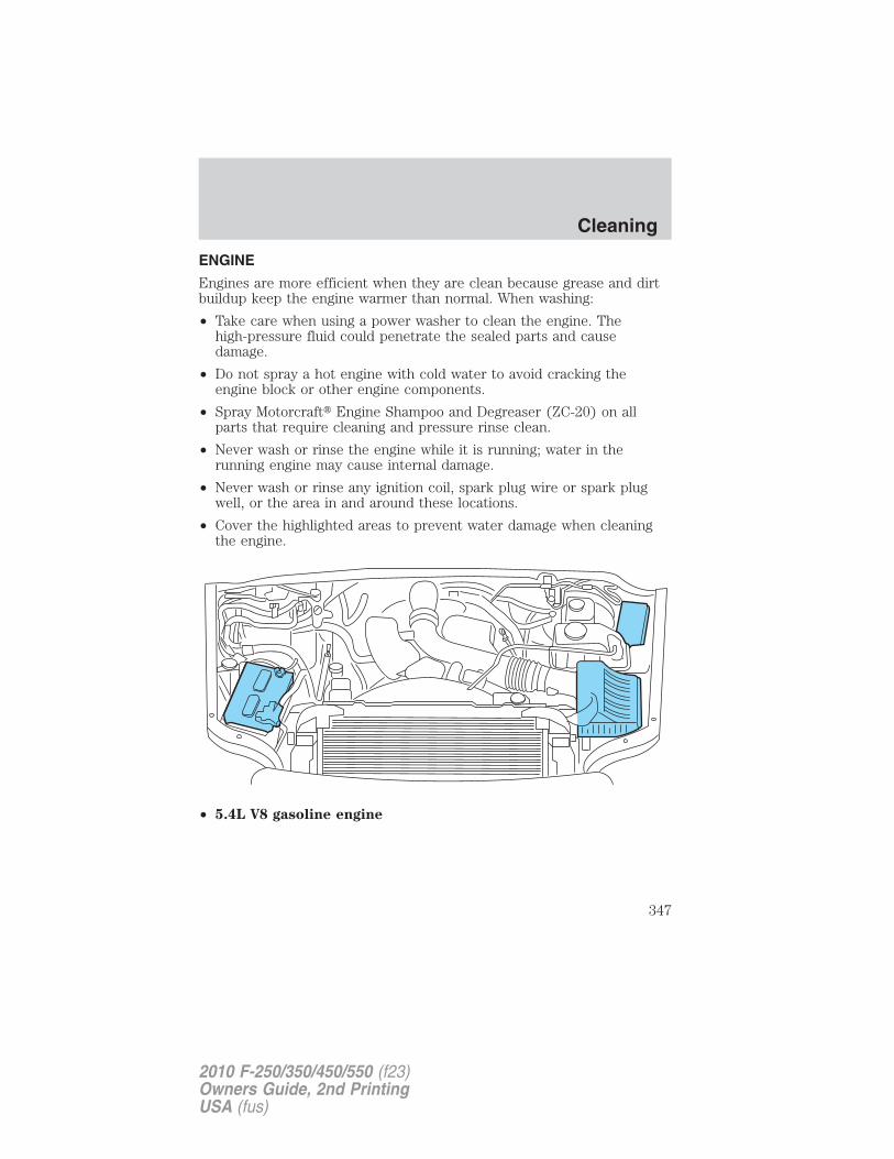
ENGINE
Engines are more efficient when they are clean because grease and dirtbuildup keep the engine warmer than normal. When washing:
• Take care when using a power washer to clean the engine. Thehigh-pressure fluid could penetrate the sealed parts and causedamage.
• Do not spray a hot engine with cold water to avoid cracking theengine block or other engine components.
• Spray Motorcraft� Engine Shampoo and Degreaser (ZC-20) on allparts that require cleaning and pressure rinse clean.
• Never wash or rinse the engine while it is running; water in therunning engine may cause internal damage.
• Never wash or rinse any ignition coil, spark plug wire or spark plugwell, or the area in and around these locations.
• Cover the highlighted areas to prevent water damage when cleaningthe engine.
• 5.4L V8 gasoline engine
Cleaning
347
2010 F-250/350/450/550 (f23)Owners Guide, 2nd PrintingUSA (fus)
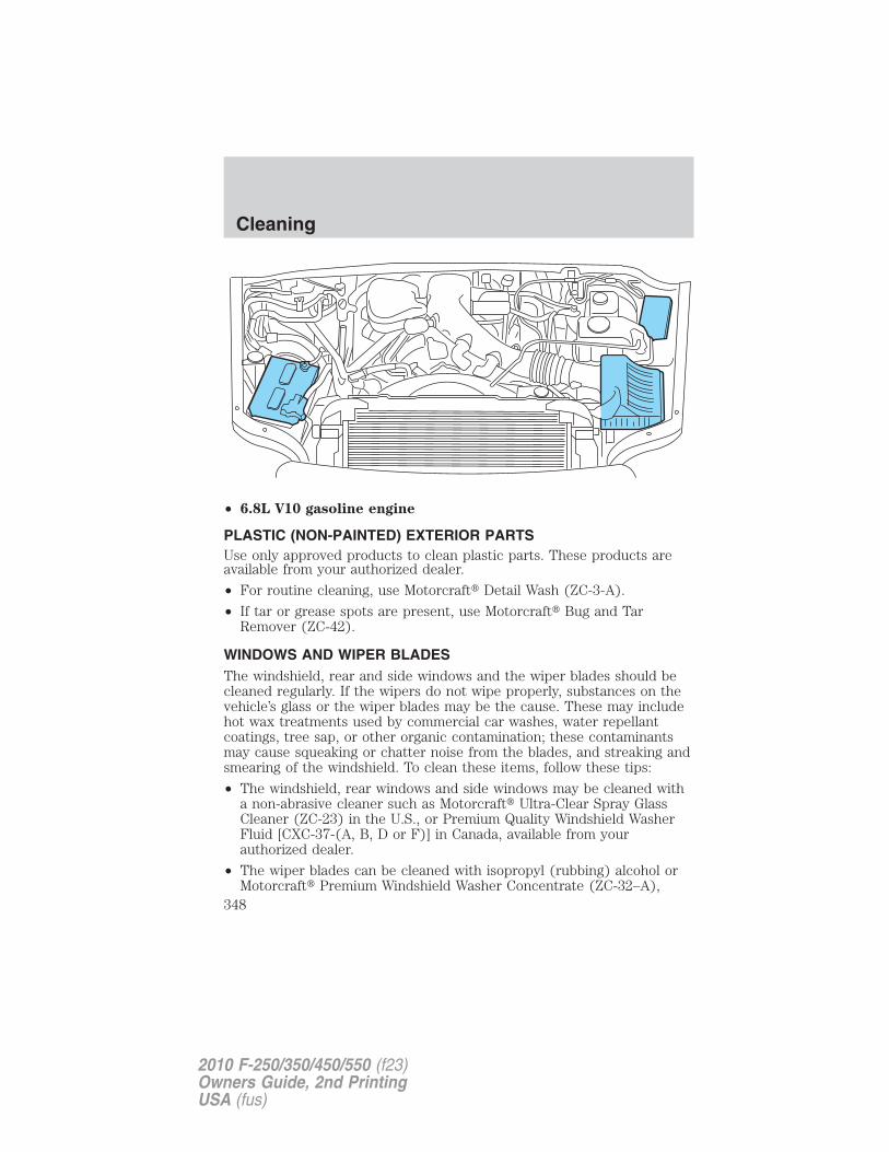
• 6.8L V10 gasoline engine
PLASTIC (NON-PAINTED) EXTERIOR PARTSUse only approved products to clean plastic parts. These products areavailable from your authorized dealer.
• For routine cleaning, use Motorcraft� Detail Wash (ZC-3-A).
• If tar or grease spots are present, use Motorcraft� Bug and TarRemover (ZC-42).
WINDOWS AND WIPER BLADESThe windshield, rear and side windows and the wiper blades should becleaned regularly. If the wipers do not wipe properly, substances on thevehicle’s glass or the wiper blades may be the cause. These may includehot wax treatments used by commercial car washes, water repellantcoatings, tree sap, or other organic contamination; these contaminantsmay cause squeaking or chatter noise from the blades, and streaking andsmearing of the windshield. To clean these items, follow these tips:
• The windshield, rear windows and side windows may be cleaned witha non-abrasive cleaner such as Motorcraft� Ultra-Clear Spray GlassCleaner (ZC-23) in the U.S., or Premium Quality Windshield WasherFluid [CXC-37-(A, B, D or F)] in Canada, available from yourauthorized dealer.
• The wiper blades can be cleaned with isopropyl (rubbing) alcohol orMotorcraft� Premium Windshield Washer Concentrate (ZC-32–A),
Cleaning
348
2010 F-250/350/450/550 (f23)Owners Guide, 2nd PrintingUSA (fus)
available from your authorized dealer. This washer fluid containsspecial solution in addition to alcohol which helps to remove the hotwax deposited on the wiper blade and windshield from automated carwash facilities. Be sure to replace wiper blades when they appearworn or do not function properly.
• Do not use abrasives, as they may cause scratches.• Do not use fuel, kerosene, or paint thinner to clean any parts.
INSTRUMENT PANEL/INTERIOR TRIM AND CLUSTER LENS(EXCEPT HARLEY-DAVIDSON)Clean the instrument panel, interior trim areas and cluster lens with aclean and damp, white cotton cloth, then with a clean and dry, whitecotton cloth.• Avoid cleaners or polishes that increase the gloss of the upper portion
of the instrument panel. The dull finish in this area helps protect thedriver from undesirable windshield reflection.
• Be certain to wash or wipe your hands clean if you have been incontact with certain products such as insect repellent and suntanlotion in order to avoid possible damage to the interior paintedsurfaces.
• Do not use household or glass cleaners as these may damage thefinish of the instrument panel, interior trim and cluster lens.
WARNING: Do not use chemical solvents or strong detergentswhen cleaning the steering wheel or instrument panel to avoid
contamination of the airbag system.
If a staining liquid like coffee/juice has been spilled on the instrumentpanel or on interior trim surfaces, clean as follows:
1. Wipe up spilled liquid using a clean white cotton cloth.
2. Wipe the surface with a damp, clean, white cotton cloth. For morethorough cleaning, use a mild soap and water solution. If the spot cannotbe completely cleaned by this method, the area may be cleaned using acommercially available cleaning product designed for automotiveinteriors.
3. If necessary, apply more soap and water solution or cleaning productto a clean, white, cotton cloth and press the cloth onto the soiledarea–allow this to set at room temperature for 30 minutes.
4. Remove the soaked cloth, and if it is not soiled badly, use this cloth toclean the area by using a rubbing motion for 60 seconds.
Cleaning
349
2010 F-250/350/450/550 (f23)Owners Guide, 2nd PrintingUSA (fus)
5. Following this, wipe area dry with a clean, white, cotton cloth.
INSTRUMENT PANEL AND CONSOLE (HARLEY-DAVIDSON ONLY)Your vehicle’s instrument panel and console are uniquely painted withboth high and low gloss paints that require special care. The high glossarea is similar to that of the vehicle’s exterior; the low gloss area isdesigned to help protect the driver from undesirable windshieldreflection.
High gloss paint area
In order to maintain the finish of the instrument panel and console, thehigh gloss areas should be treated similar to the that of exterior paint orglossy plastic surfaces. When cleaning the high gloss areas:
• Do not use paper towels or newspaper.
• Do not use silicone or Teflont� (PTFE)-based products.
Dust the high gloss areas with a clean, dry cloth, or use Motorcraft�Dusting Cloth (ZC-24 or ZC-25) or Motorcraft� Dusting Cloth Mitts(ZC-47).
For general cleaning, use mild, soapy water and a soft, damp cloth, thendry with a clean, dry cloth; or Motorcraft� Ultra-Clear Spray GlassCleaner (ZC-23).
For removal of fine scuffs and scratches, use Scotch-Brite MicrofiberCloth or cheese cloth along with Motorcraft� Premium Liquid Wax(ZC-53-A), Motorcraft� Paint Sealant (ZC-45), or Motorcraft� CustomClear Coat Polish (ZC-8-A). Note: Removal of deep scuffs and scratchesshould be performed by an authorized dealer or an experienced repairfacility.
Low gloss paint area
The low gloss area of the instrument panel’s upper dash should becleaned with mild, soapy water and a soft, damp cloth, then dried with aclean, dry cloth. When cleaning the low gloss areas:
• Do not use paper towels or newspaper.
• Do not use silicone or Teflont� (PTFE)-based products.
• Do not use exterior paint waxes or sealants.
Dust the low gloss areas with a clean, dry cloth, or use Motorcraft�Dusting Cloth (ZC-24 or ZC-25) or Motorcraft� Dusting Cloth Mitts(ZC-47).
Cleaning
350
2010 F-250/350/450/550 (f23)Owners Guide, 2nd PrintingUSA (fus)
INTERIORFor fabric, carpets, cloth seats and safety belts:• Remove dust and loose dirt with a vacuum cleaner.• Remove light stains and soil with Motorcraft� Professional Strength
Carpet & Upholstery Cleaner (ZC-54).• If grease or tar is present on the material, spot-clean the area first
with Motorcraft� Spot and Stain Remover (ZC-14). In Canada, useMotorcraft� Multi-Purpose Cleaner (CXC-101).
• If a ring forms on the fabric after spot cleaning, clean the entire areaimmediately (but do not oversaturate) or the ring will set.
• Do not use household cleaning products or glass cleaners, which canstain and discolor the fabric and affect the flame retardant abilities ofthe seat materials.
WARNING: Do not use cleaning solvents, bleach or dye on thevehicle’s seatbelts, as these actions may weaken the belt
webbing.
LEATHER SEATS (IF EQUIPPED, EXCEPT FOR THE KING RANCHF–250 AND F–350 CREW CAB)Your leather seating surfaces have a clear, protective coating over theleather.
For King Ranch F-250 and F-350 Crew Cab leather seats, refer toseparate section in this chapter.
• For routine cleaning, wipe the surface with a soft, damp cloth. Formore thorough cleaning, wipe the surface with a mild soap and watersolution. In Canada, use Motorcraft� Vinyl Cleaner (CXC-93). Dry thearea with a soft cloth.
• If the leather cannot be completely cleaned using a mild soap andwater solution, the leather may be cleaned using a commerciallyavailable cleaning product designed for automotive interiors.
• Do not use household cleaning products, alcohol solutions, solvents orcleaners intended for rubber, vinyl and plastics, or oil/petroleum-basedleather conditioners. These products may cause premature wearing ofthe clear, protective coating on the seat.
Note: In some instances, color or dye transfer can occur when wetclothing comes in contact with leather upholstery. If this occurs, theleather should be cleaned immediately to avoid permanent staining.
Cleaning
351
2010 F-250/350/450/550 (f23)Owners Guide, 2nd PrintingUSA (fus)
LEATHER SEATS FOR THE KING RANCH F-250 AND F-350 CREWCAB ONLY (IF EQUIPPED)Your vehicle is equipped with seating covered in premium, top-grainleather which is extremely durable, but still requires special care andmaintenance in order to ensure longevity and comfort.
Regular cleaning and conditioning will maintain the appearance of theleather. Failure to care for the leather can result in drying out and fadingof the material.
Note: In some instances, color or dye transfer can occur when wetclothing comes in contact with leather upholstery. If this occurs, theleather should be cleaned immediately to avoid permanent staining.
Cleaning
For dirt, use a vacuum cleaner then use a clean, damp cloth or softbrush.
For routine cleaning, wipe the surface with a soft, damp cloth. For morethorough cleaning, wipe the surface with a mild soap. If the leathercannot be completely cleaned using a mild soap and water solution, theleather may be cleaned using a commercially available cleaning product“Tanners Preserve Leather Cleaner” and a 3M “Type T” scrubbing pad.
• Clean spills as quickly as possible.
• Test any cleaner or stain remover on an inconspicuous part of theleather as cleaners may darken the leather. For more specific cleaninginformation, contact the King Ranch Saddle Shop at 1–800–282–KING(5464).
• Do not spill coffee, ketchup, mustard, orange juice or oil-basedproducts on the leather as they may permanently stain the leather.
• Do not use household cleaning products, alcohol solutions, solvents orcleaners intended for rubber, vinyl or plastics.
Scratches
Natural Markings - Because the leather in the seat comes from genuinesteer hides, there will be evidence of naturally occurring markings, suchas small scars. These markings give character to the seating covers andshould be considered as proof of a genuine leather product.
In order to lessen the appearance of certain scratches and other wearmarks, apply conditioner on the affected area following the sameinstructions as in the Conditioning section.
Cleaning
352
2010 F-250/350/450/550 (f23)Owners Guide, 2nd PrintingUSA (fus)
Conditioning
Bottles of King Ranch Leather Conditioner are available at the KingRanch Saddle Shop. Visit the Web site at www.krsaddleshop.com, ortelephone (in the United States) 1–800–282–KING (5464). If you areunable to obtain King Ranch Leather Conditioner, use another premiumleather conditioner.• Apply your first conditioning treatment within six months of taking
delivery of your vehicle. Condition twice yearly in order to replenishlost oils and revitalize the aroma, suppleness and resilience of theleather.
• Clean the surfaces using the steps outlined in the Cleaning section.• Ensure the leather is dry then apply a nickel-sized amount of
conditioner to a clean, dry cloth
• Rub the conditioner into leather until it disappears. Allow theconditioner to dry and repeat the process for the entire interior. If afilm appears, wipe off film with a dry, clean cloth.
UNDERBODYFlush the complete underside of your vehicle frequently. Keep body anddoor drain holes free from packed dirt.
Note: Use care when using a power washer to clean the driveline,especially the driveshaft and interfacing components. The high-pressurefluid could penetrate the sealed parts and cause damage.
FORD, LINCOLN AND MERCURY CAR CARE PRODUCTSYour authorized dealer has many quality products available to clean yourvehicle and protect its finishes. These quality products have beenspecifically engineered to fulfill your automotive needs; they are customdesigned to complement the style and appearance of your vehicle. Eachproduct is made from high quality materials that meet or exceed rigidspecifications. For best results, use the following products or products ofequivalent quality:
Motorcraft� Bug and Tar Remover (ZC-42)
Motorcraft� Car Care Kit (ZC-26)
Motorcraft� Custom Bright Metal Cleaner (ZC-15)
Motorcraft� Custom Clear Coat Polish (ZC–8–A)
Motorcraft� Detail Wash (ZC-3–A)
Motorcraft� Dusting Cloth (ZC-24)
Cleaning
353
2010 F-250/350/450/550 (f23)Owners Guide, 2nd PrintingUSA (fus)
Motorcraft� Engine Shampoo and Degreaser (U.S only) (ZC-20)
Motorcraft� Engine Shampoo (Canada only) (CXC-66-A)
Motorcraft� Multi-Purpose Cleaner (Canada only) (CXC-101)
Motorcraft� Premium Car Wash Concentrate (U.S. only) (ZC-17-B)
Motorcraft� Premium Glass Cleaner (Canada only) (CXC-100)
Motorcraft� Premium Liquid Wax (ZC-53–A)
Motorcraft� Professional Strength Carpet & Upholstery Cleaner (ZC-54)
Motorcraft� Spot and Stain Remover (U.S. only) (ZC-14)
Motorcraft� Tire Clean and Shine (ZC-28)
Motorcraft� Ultra-Clear Spray Glass Cleaner (ZC-23)
Motorcraft� Vinyl Cleaner (Canada only) (CXC-93)
Motorcraft� Vinyl Conditioner (Canada only) (CXC-94)
Motorcraft� Wheel and Tire Cleaner (ZC-37–A)
Cleaning
354
2010 F-250/350/450/550 (f23)Owners Guide, 2nd PrintingUSA (fus)
SERVICE RECOMMENDATIONSTo help you service your vehicle, we provide scheduled maintenanceinformation which makes tracking routine service easy.
If your vehicle requires professional service, your authorized dealer canprovide the necessary parts and service. Check your WarrantyGuide/Customer Information Guide to find out which parts andservices are covered.
Use only recommended fuels, lubricants, fluids and service partsconforming to specifications. Motorcraft� parts are designed and built toprovide the best performance in your vehicle.
PRECAUTIONS WHEN SERVICING YOUR VEHICLE• Do not work on a hot engine.
• Make sure that nothing gets caught in moving parts.
• Do not work on a vehicle with the engine running in an enclosedspace, unless you are sure you have enough ventilation.
• Keep all open flames and other burning material (such as cigarettes)away from the battery and all fuel related parts.
Working with the engine off1. For vehicles equipped with an automatic transmission, set the parkingbrake and shift to P (Park). For vehicles equipped with a manualtransmission, set the parking brake, press and hold the clutch pedal,place the gearshift in 1 (First), and release the clutch pedal.
2. Turn off the engine and remove the key.
3. Block the wheels.
Working with the engine on1. For vehicles equipped with an automatic transmission, set the parkingbrake and shift to P (Park). For vehicles equipped with a manualtransmission, set the parking brake, press and hold the clutch pedal,place the gearshift in N (Neutral), and release the clutch pedal.
2. Block the wheels.
WARNING: To reduce the risk of vehicle damage and/orpersonal burn injuries, do not start your engine with the air
cleaner removed and do not remove it while the engine is running.
Maintenance and Specifications
355
2010 F-250/350/450/550 (f23)Owners Guide, 2nd PrintingUSA (fus)
OPENING THE HOOD
1. Inside the vehicle, pull the hoodrelease handle located under thebottom left corner of the instrumentpanel.
2. Go to the front of the vehicle andrelease the auxiliary latch locatedbelow the passenger side of thegrille, next to the headlamp. Slidethe handle to release the auxiliarylatch.
3. Lift the hood until the liftcylinders hold it open.
Maintenance and Specifications
356
2010 F-250/350/450/550 (f23)Owners Guide, 2nd PrintingUSA (fus)
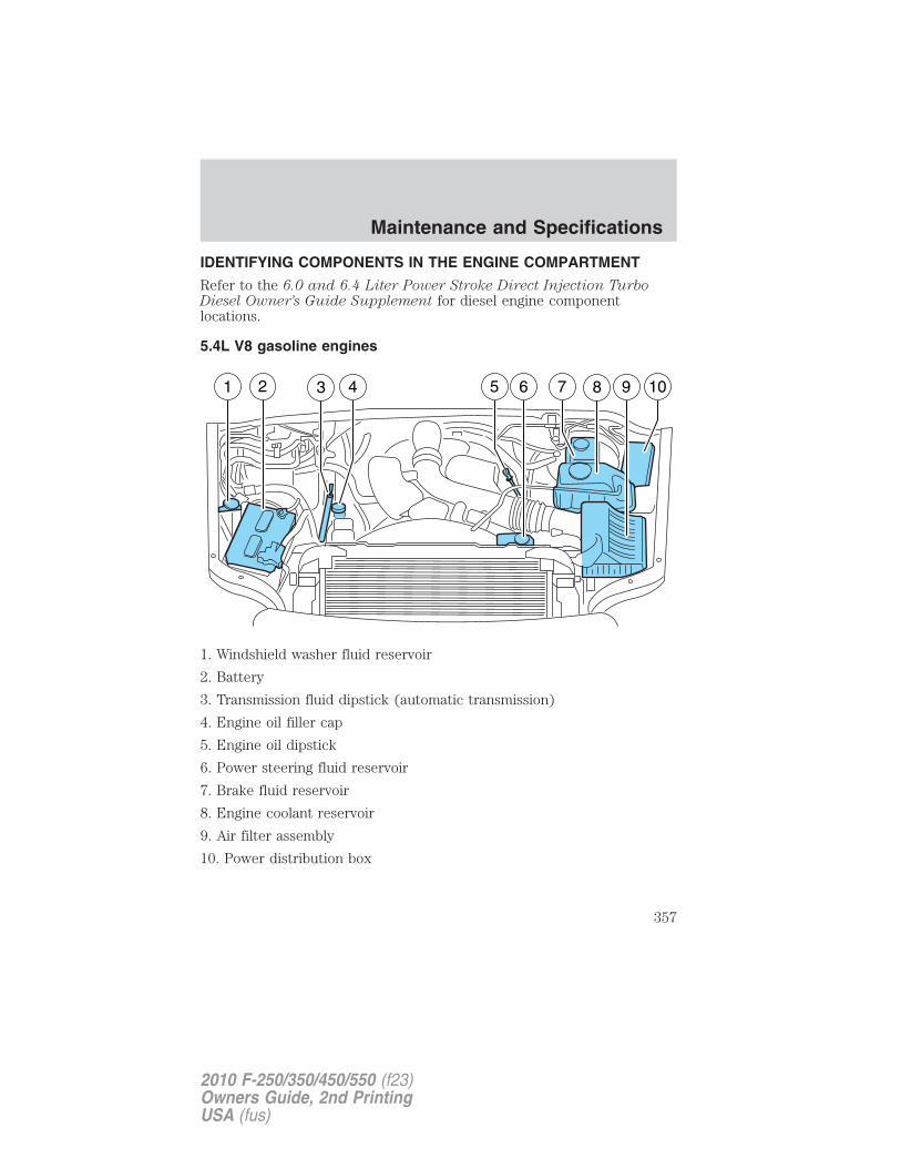
IDENTIFYING COMPONENTS IN THE ENGINE COMPARTMENT
Refer to the 6.0 and 6.4 Liter Power Stroke Direct Injection TurboDiesel Owner’s Guide Supplement for diesel engine componentlocations.
5.4L V8 gasoline engines
1. Windshield washer fluid reservoir
2. Battery
3. Transmission fluid dipstick (automatic transmission)
4. Engine oil filler cap
5. Engine oil dipstick
6. Power steering fluid reservoir
7. Brake fluid reservoir
8. Engine coolant reservoir
9. Air filter assembly
10. Power distribution box
Maintenance and Specifications
357
2010 F-250/350/450/550 (f23)Owners Guide, 2nd PrintingUSA (fus)
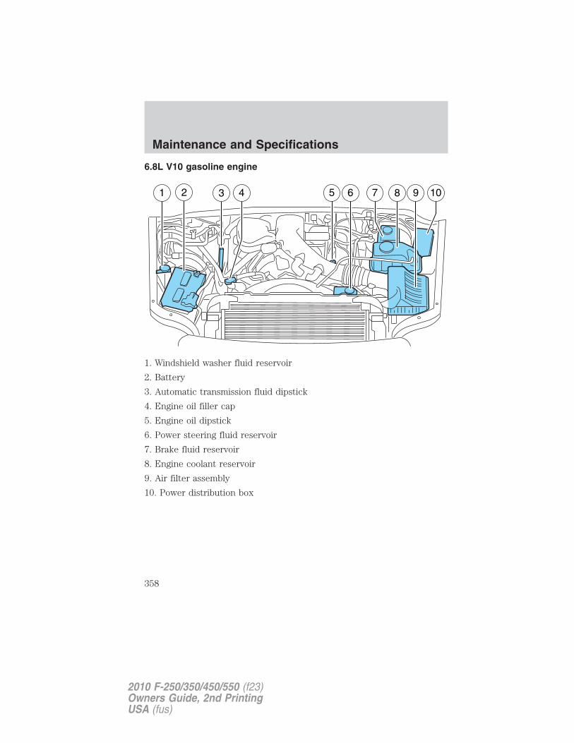
6.8L V10 gasoline engine
1. Windshield washer fluid reservoir
2. Battery
3. Automatic transmission fluid dipstick
4. Engine oil filler cap
5. Engine oil dipstick
6. Power steering fluid reservoir
7. Brake fluid reservoir
8. Engine coolant reservoir
9. Air filter assembly
10. Power distribution box
Maintenance and Specifications
358
2010 F-250/350/450/550 (f23)Owners Guide, 2nd PrintingUSA (fus)
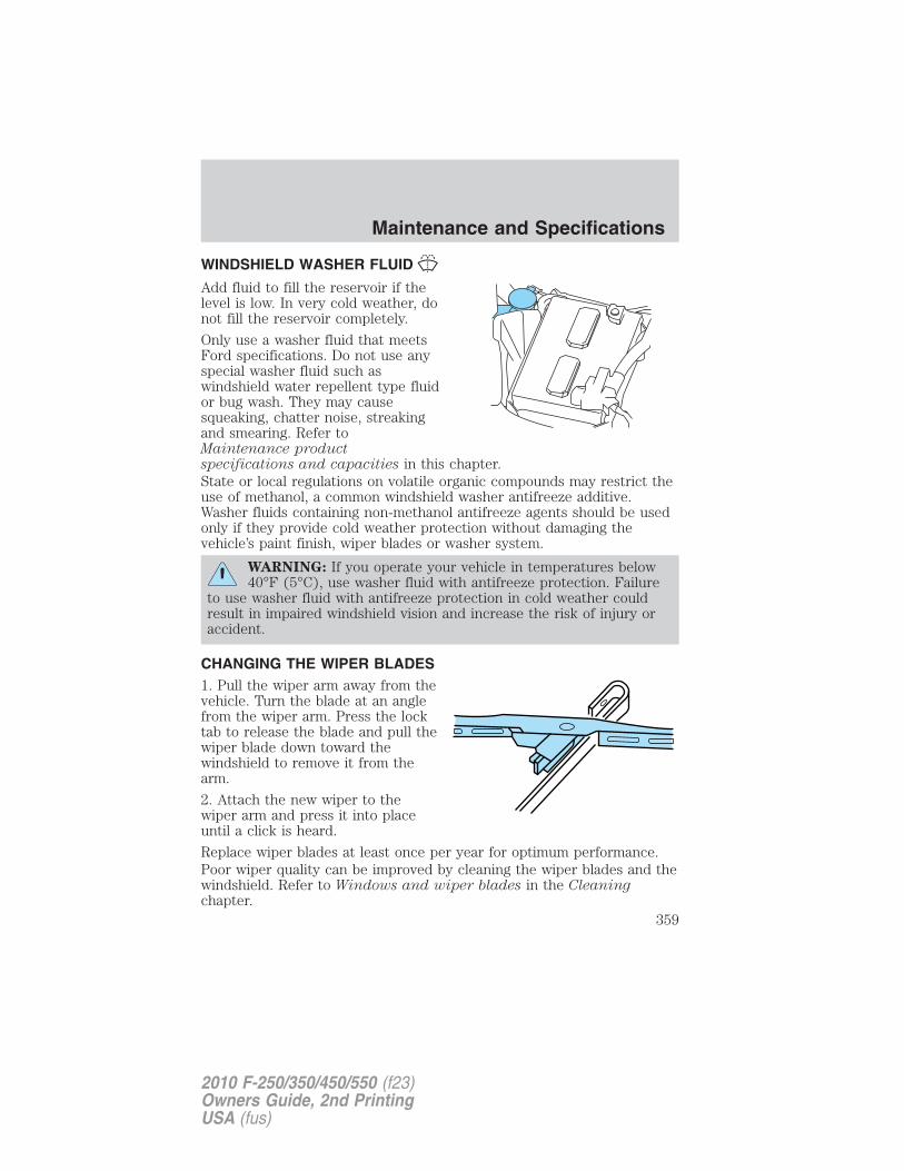
WINDSHIELD WASHER FLUID
Add fluid to fill the reservoir if thelevel is low. In very cold weather, donot fill the reservoir completely.
Only use a washer fluid that meetsFord specifications. Do not use anyspecial washer fluid such aswindshield water repellent type fluidor bug wash. They may causesqueaking, chatter noise, streakingand smearing. Refer toMaintenance productspecifications and capacities in this chapter.State or local regulations on volatile organic compounds may restrict theuse of methanol, a common windshield washer antifreeze additive.Washer fluids containing non-methanol antifreeze agents should be usedonly if they provide cold weather protection without damaging thevehicle’s paint finish, wiper blades or washer system.
WARNING: If you operate your vehicle in temperatures below40°F (5°C), use washer fluid with antifreeze protection. Failure
to use washer fluid with antifreeze protection in cold weather couldresult in impaired windshield vision and increase the risk of injury oraccident.
CHANGING THE WIPER BLADES1. Pull the wiper arm away from thevehicle. Turn the blade at an anglefrom the wiper arm. Press the locktab to release the blade and pull thewiper blade down toward thewindshield to remove it from thearm.
2. Attach the new wiper to thewiper arm and press it into placeuntil a click is heard.
Replace wiper blades at least once per year for optimum performance.Poor wiper quality can be improved by cleaning the wiper blades and thewindshield. Refer to Windows and wiper blades in the Cleaningchapter.
Maintenance and Specifications
359
2010 F-250/350/450/550 (f23)Owners Guide, 2nd PrintingUSA (fus)
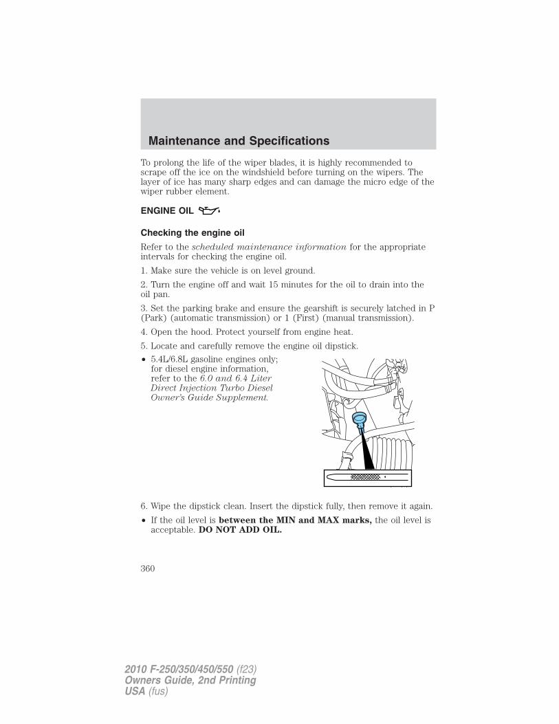
To prolong the life of the wiper blades, it is highly recommended toscrape off the ice on the windshield before turning on the wipers. Thelayer of ice has many sharp edges and can damage the micro edge of thewiper rubber element.
ENGINE OIL
Checking the engine oil
Refer to the scheduled maintenance information for the appropriateintervals for checking the engine oil.
1. Make sure the vehicle is on level ground.
2. Turn the engine off and wait 15 minutes for the oil to drain into theoil pan.
3. Set the parking brake and ensure the gearshift is securely latched in P(Park) (automatic transmission) or 1 (First) (manual transmission).
4. Open the hood. Protect yourself from engine heat.
5. Locate and carefully remove the engine oil dipstick.
• 5.4L/6.8L gasoline engines only;for diesel engine information,refer to the 6.0 and 6.4 LiterDirect Injection Turbo DieselOwner’s Guide Supplement.
6. Wipe the dipstick clean. Insert the dipstick fully, then remove it again.
• If the oil level is between the MIN and MAX marks, the oil level isacceptable. DO NOT ADD OIL.
Maintenance and Specifications
360
2010 F-250/350/450/550 (f23)Owners Guide, 2nd PrintingUSA (fus)
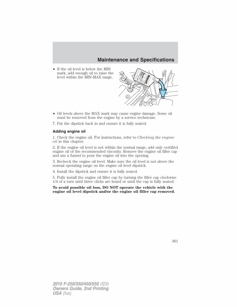
• If the oil level is below the MINmark, add enough oil to raise thelevel within the MIN-MAX range.
• Oil levels above the MAX mark may cause engine damage. Some oilmust be removed from the engine by a service technician.
7. Put the dipstick back in and ensure it is fully seated.
Adding engine oil
1. Check the engine oil. For instructions, refer to Checking the engineoil in this chapter.
2. If the engine oil level is not within the normal range, add only certifiedengine oil of the recommended viscosity. Remove the engine oil filler capand use a funnel to pour the engine oil into the opening.
3. Recheck the engine oil level. Make sure the oil level is not above thenormal operating range on the engine oil level dipstick.
4. Install the dipstick and ensure it is fully seated.
5. Fully install the engine oil filler cap by turning the filler cap clockwise1/4 of a turn until three clicks are heard or until the cap is fully seated.
To avoid possible oil loss, DO NOT operate the vehicle with theengine oil level dipstick and/or the engine oil filler cap removed.
Maintenance and Specifications
361
2010 F-250/350/450/550 (f23)Owners Guide, 2nd PrintingUSA (fus)
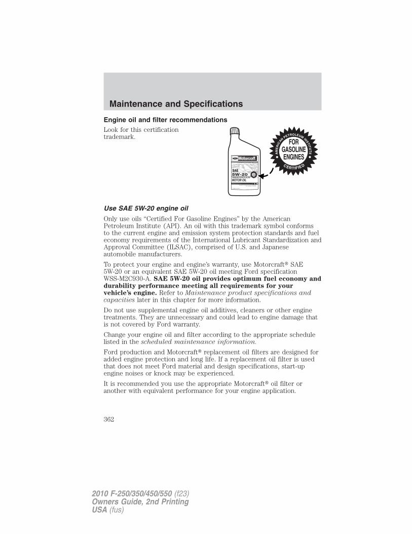
Engine oil and filter recommendationsLook for this certificationtrademark.
Use SAE 5W-20 engine oil
Only use oils “Certified For Gasoline Engines” by the AmericanPetroleum Institute (API). An oil with this trademark symbol conformsto the current engine and emission system protection standards and fueleconomy requirements of the International Lubricant Standardization andApproval Committee (ILSAC), comprised of U.S. and Japaneseautomobile manufacturers.
To protect your engine and engine’s warranty, use Motorcraft� SAE5W-20 or an equivalent SAE 5W-20 oil meeting Ford specificationWSS-M2C930-A. SAE 5W-20 oil provides optimum fuel economy anddurability performance meeting all requirements for yourvehicle’s engine. Refer to Maintenance product specifications andcapacities later in this chapter for more information.
Do not use supplemental engine oil additives, cleaners or other enginetreatments. They are unnecessary and could lead to engine damage thatis not covered by Ford warranty.
Change your engine oil and filter according to the appropriate schedulelisted in the scheduled maintenance information.
Ford production and Motorcraft� replacement oil filters are designed foradded engine protection and long life. If a replacement oil filter is usedthat does not meet Ford material and design specifications, start-upengine noises or knock may be experienced.
It is recommended you use the appropriate Motorcraft� oil filter oranother with equivalent performance for your engine application.
Maintenance and Specifications
362
2010 F-250/350/450/550 (f23)Owners Guide, 2nd PrintingUSA (fus)
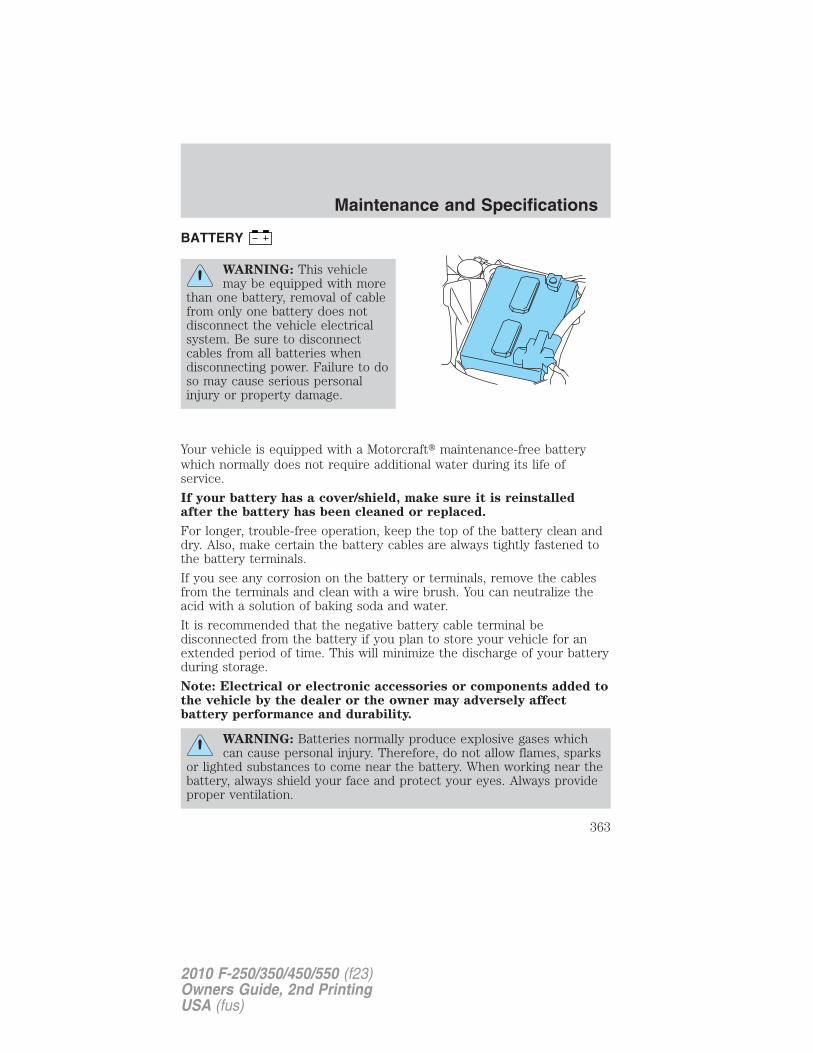
BATTERY
WARNING: This vehiclemay be equipped with more
than one battery, removal of cablefrom only one battery does notdisconnect the vehicle electricalsystem. Be sure to disconnectcables from all batteries whendisconnecting power. Failure to doso may cause serious personalinjury or property damage.
Your vehicle is equipped with a Motorcraft� maintenance-free batterywhich normally does not require additional water during its life ofservice.
If your battery has a cover/shield, make sure it is reinstalledafter the battery has been cleaned or replaced.
For longer, trouble-free operation, keep the top of the battery clean anddry. Also, make certain the battery cables are always tightly fastened tothe battery terminals.
If you see any corrosion on the battery or terminals, remove the cablesfrom the terminals and clean with a wire brush. You can neutralize theacid with a solution of baking soda and water.
It is recommended that the negative battery cable terminal bedisconnected from the battery if you plan to store your vehicle for anextended period of time. This will minimize the discharge of your batteryduring storage.
Note: Electrical or electronic accessories or components added tothe vehicle by the dealer or the owner may adversely affectbattery performance and durability.
WARNING: Batteries normally produce explosive gases whichcan cause personal injury. Therefore, do not allow flames, sparks
or lighted substances to come near the battery. When working near thebattery, always shield your face and protect your eyes. Always provideproper ventilation.
Maintenance and Specifications
363
2010 F-250/350/450/550 (f23)Owners Guide, 2nd PrintingUSA (fus)
WARNING: When lifting a plastic-cased battery, excessivepressure on the end walls could cause acid to flow through the
vent caps, resulting in personal injury and/or damage to the vehicle orbattery. Lift the battery with a battery carrier or with your hands onopposite corners.
WARNING: Keep batteries out of reach of children. Batteriescontain sulfuric acid. Avoid contact with skin, eyes or clothing.
Shield your eyes when working near the battery to protect againstpossible splashing of acid solution. In case of acid contact with skin oreyes, flush immediately with water for a minimum of 15 minutes andget prompt medical attention. If acid is swallowed, call a physicianimmediately.
WARNING: Battery posts, terminals and related accessoriescontain lead and lead compounds. Wash hands after handling.
Because your vehicle’s engine is also electronically controlled by acomputer, some control conditions are maintained by power from thebattery. When the battery is disconnected or a new battery is installed,the engine must relearn its idle and fuel trim strategy for optimumdriveability and performance. To begin this process:1. With the vehicle at a complete stop, set the parking brake.2. Put the gearshift in P (Park) (automatic transmission) or the neutralposition (manual transmission), turn off all accessories and start theengine.3. Run the engine until it reaches normal operating temperature.4. Allow the engine to idle for at least one minute.5. Turn the A/C on and allow the engine to idle for at least one minute.6. Drive the vehicle to complete the relearning process.• The vehicle may need to be driven 10 miles (16 km) or more to
relearn the idle and fuel trim strategy.• If you do not allow the engine to relearn its idle trim, the idle
quality of your vehicle may be adversely affected until the idletrim is eventually relearned.
If the battery has been disconnected or a new battery has been installed,the clock and the preset radio stations must be reset once the battery isreconnected.
Maintenance and Specifications
364
2010 F-250/350/450/550 (f23)Owners Guide, 2nd PrintingUSA (fus)
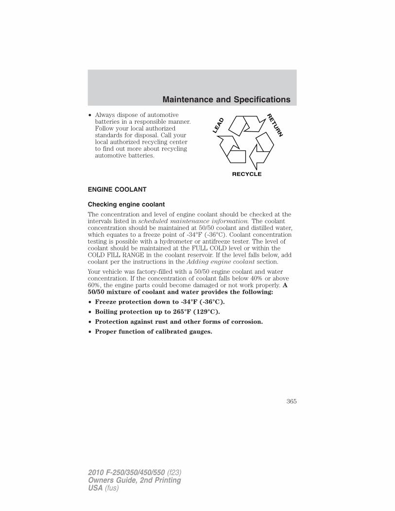
• Always dispose of automotivebatteries in a responsible manner.Follow your local authorizedstandards for disposal. Call yourlocal authorized recycling centerto find out more about recyclingautomotive batteries.
ENGINE COOLANT
Checking engine coolant
The concentration and level of engine coolant should be checked at theintervals listed in scheduled maintenance information. The coolantconcentration should be maintained at 50/50 coolant and distilled water,which equates to a freeze point of -34°F (-36°C). Coolant concentrationtesting is possible with a hydrometer or antifreeze tester. The level ofcoolant should be maintained at the FULL COLD level or within theCOLD FILL RANGE in the coolant reservoir. If the level falls below, addcoolant per the instructions in the Adding engine coolant section.
Your vehicle was factory-filled with a 50/50 engine coolant and waterconcentration. If the concentration of coolant falls below 40% or above60%, the engine parts could become damaged or not work properly. A50/50 mixture of coolant and water provides the following:
• Freeze protection down to -34°F (-36°C).
• Boiling protection up to 265°F (129°C).
• Protection against rust and other forms of corrosion.
• Proper function of calibrated gauges.
LE
AD
RE
TU
RN
RECYCLE
Maintenance and Specifications
365
2010 F-250/350/450/550 (f23)Owners Guide, 2nd PrintingUSA (fus)
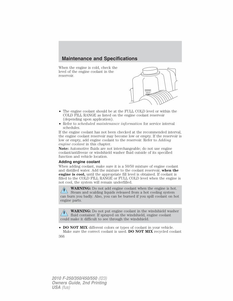
When the engine is cold, check thelevel of the engine coolant in thereservoir.
• The engine coolant should be at the FULL COLD level or within theCOLD FILL RANGE as listed on the engine coolant reservoir(depending upon application).
• Refer to scheduled maintenance information for service intervalschedules.
If the engine coolant has not been checked at the recommended interval,the engine coolant reservoir may become low or empty. If the reservoir islow or empty, add engine coolant to the reservoir. Refer to Addingengine coolant in this chapter.Note: Automotive fluids are not interchangeable; do not use enginecoolant/antifreeze or windshield washer fluid outside of its specifiedfunction and vehicle location.
Adding engine coolantWhen adding coolant, make sure it is a 50/50 mixture of engine coolantand distilled water. Add the mixture to the coolant reservoir, when theengine is cool, until the appropriate fill level is obtained. If coolant isfilled to the COLD FILL RANGE or FULL COLD level when the engine isnot cool, the system will remain underfilled.
WARNING: Do not add engine coolant when the engine is hot.Steam and scalding liquids released from a hot cooling system
can burn you badly. Also, you can be burned if you spill coolant on hotengine parts.
WARNING: Do not put engine coolant in the windshield washerfluid container. If sprayed on the windshield, engine coolant
could make it difficult to see through the windshield.
• DO NOT MIX different colors or types of coolant in your vehicle.Make sure the correct coolant is used. DO NOT MIX recycled coolant
Maintenance and Specifications
366
2010 F-250/350/450/550 (f23)Owners Guide, 2nd PrintingUSA (fus)
and virgin coolant together in the vehicle. Mixing of engine coolantsmay harm your engine’s cooling system. The use of an impropercoolant may harm engine and cooling system components and mayvoid the warranty. Refer to Maintenance product specifications andcapacities in this chapter.
Note: Do not use stop leak pellets or cooling system sealants/additivesas they can cause damage to the engine cooling and/or heating systems.This damage would not be covered under your vehicle’s warranty.• A large amount of water without engine coolant may be added, in case
of emergency, to reach a vehicle service location. In this instance, thecooling system must be drained and refilled with a 50/50 mixture ofengine coolant and distilled water as soon as possible. Water alone(without engine coolant) can cause engine damage from corrosion,overheating or freezing.
• Do not use alcohol, methanol, brine or any engine coolantsmixed with alcohol or methanol antifreeze (coolant). Alcoholand other liquids can cause engine damage from overheating orfreezing.
• Do not add extra inhibitors or additives to the coolant. Thesecan be harmful and compromise the corrosion protection of the enginecoolant.
For vehicles with overflow coolant systems with a non-pressurized capon the coolant recovery system, add coolant to the coolant recoveryreservoir when the engine is cool. Add the proper mixture of coolant andwater to the FULL COLD level. For all other vehicles which have acoolant degas system with a pressurized cap, or if it is necessary toremove the coolant pressure relief cap on the radiator of a vehicle withan overflow system, follow these steps to add engine coolant.
WARNING: To reduce the risk of personal injury, make sure theengine is cool before unscrewing the coolant pressure relief cap.
The cooling system is under pressure; steam and hot liquid can comeout forcefully when the cap is loosened slightly.
Add the proper mixture of coolant and water to the cooling system byfollowing these steps:
1. Before you begin, turn the engine off and let it cool.
2. When the engine is cool, wrap a thick cloth around the coolantpressure relief cap on the coolant reservoir (a translucent plastic bottle).Slowly turn cap counterclockwise (left) until pressure begins to release.
Maintenance and Specifications
367
2010 F-250/350/450/550 (f23)Owners Guide, 2nd PrintingUSA (fus)
3. Step back while the pressure releases.4. When you are sure that all the pressure has been released, use thecloth to turn it counterclockwise and remove the cap.
5. Fill the coolant reservoir slowly with the proper coolant mixture, towithin the COLD FILL RANGE or the FULL COLD level on the reservoir.If you removed the radiator cap in an overflow system, fill the radiatoruntil the coolant is visible and radiator is almost full.
6. Replace the cap. Turn until tightly installed. Cap must be tightlyinstalled to prevent coolant loss.
After any coolant has been added, check the coolant concentration (referto Checking engine coolant). If the concentration is not 50/50(protection to –34°F/–36°C), drain some coolant and adjust theconcentration. It may take several drains and additions to obtain a 50/50coolant concentration.
Whenever coolant has been added, the coolant level in the coolantreservoir should be checked the next few times you drive the vehicle. Ifnecessary, add enough 50/50 concentration of engine coolant anddistilled water to bring the liquid level to the proper level.
If you have to add more than 1.0 quart (1.0 liter) of engine coolant permonth, have your authorized dealer check the engine cooling system.Your cooling system may have a leak. Operating an engine with a lowlevel of coolant can result in engine overheating and possible enginedamage.
Recycled engine coolantFord Motor Company does NOT recommend the use of recycled enginecoolant since a Ford-approved recycling process is not yet available.
Used engine coolant should be disposed of in an appropriatemanner. Follow your community’s regulations and standards for recyclingand disposing of automotive fluids.
Coolant refill capacityTo find out how much fluid your vehicle’s cooling system can hold, referto Maintenance product specifications and capacities in this chapter.
If your vehicle is equipped with a diesel engine, refer to theMaintenance product specifications and capacities section of your 6.0and 6.4 Liter Power Stroke Direct Injection Turbo Diesel Owner’sGuide Supplement.
Maintenance and Specifications
368
2010 F-250/350/450/550 (f23)Owners Guide, 2nd PrintingUSA (fus)
Fill your engine coolant reservoir as outlined in Adding engine coolantin this section.
Severe climatesIf you drive in extremely cold climates (less than –34°F [–36°C]):
• It may be necessary to increase the coolant concentrationabove 50%.
• NEVER increase the coolant concentration above 60%.Increased engine coolant concentrations above 60% willdecrease the overheat protection characteristics of the enginecoolant and may cause engine damage.
• Refer to the chart on the coolant container to ensure thecoolant concentration in your vehicle will provide adequatefreeze protection at the temperatures in which you drive in thewinter months.
If you drive in extremely hot climates:
• It is still necessary to maintain the coolant concentrationabove 40%.
• NEVER decrease the coolant concentration below 40%.Decreased engine coolant concentrations below 40% willdecrease the corrosion/freeze protection characteristics of theengine coolant and may cause engine damage.
• Refer to the chart on the coolant container to ensure thecoolant concentration in your vehicle will provide adequateprotection at the temperatures in which you drive.
Vehicles driven year-round in non-extreme climates should use a 50/50mixture of engine coolant and distilled water for optimum cooling systemand engine protection.
What you should know about fail-safe cooling (if equipped)If the engine coolant supply is depleted, this feature allows the vehicle tobe driven temporarily before incremental component damage is incurred.The “fail-safe” distance depends on ambient temperatures, vehicle loadand terrain.
Maintenance and Specifications
369
2010 F-250/350/450/550 (f23)Owners Guide, 2nd PrintingUSA (fus)
How fail-safe cooling worksIf the engine begins to overheat:• The engine coolant temperature gauge will move to the red (hot)
area.• The message center will indicate the engine is overheating.
• The service engine soon indicator will illuminate.
If the engine reaches a preset over-temperature condition, the enginewill automatically switch to alternating cylinder operation. Each disabledcylinder acts as an air pump and cools the engine.When this occurs the vehicle will still operate. However:• The engine power will be limited.
• The air conditioning system will be disabled.
Continued operation will increase the engine temperature and the enginewill completely shut down, causing steering and braking effort toincrease.
Once the engine temperature cools, the engine can be re-started. Takeyour vehicle to a service facility as soon as possible to minimize enginedamage.
When fail-safe mode is activatedYou have limited engine power when in the fail-safe mode, so drive thevehicle with caution. The vehicle will not be able to maintain high-speedoperation and the engine will run rough. Remember that the engine iscapable of completely shutting down automatically to prevent enginedamage; therefore:
1. Pull off the road as soon as safely possible and turn off the engine.
2. Arrange for the vehicle to be taken to a service facility.
3. If this is not possible, wait a short period for the engine to cool.
4. Check the coolant level and replenish if low.
WARNING: Never remove the coolant reservoir cap while theengine is running or hot.
5. Re-start the engine and take your vehicle to a service facility.
Driving the vehicle without repairing the engine problemincreases the chance of engine damage. Take your vehicle to aservice facility as soon as possible.
Maintenance and Specifications
370
2010 F-250/350/450/550 (f23)Owners Guide, 2nd PrintingUSA (fus)
FUEL FILTERFor fuel filter replacement, see your authorized dealer. Refer toscheduled maintenance information for the appropriate intervals forchanging the fuel filter.
Replace the fuel filter with an authorized Motorcraft� part. Thecustomer warranty may be void for any damage to the fuel systemif an authorized Motorcraft� fuel filter is not used.
WHAT YOU SHOULD KNOW ABOUT AUTOMOTIVE FUELS
Important safety precautions
WARNING: Do not overfill the fuel tank. The pressure in anoverfilled tank may cause leakage and lead to fuel spray and fire.
WARNING: The fuel system may be under pressure. If the fuelfiller cap is venting vapor or if you hear a hissing sound, wait
until it stops before completely removing the fuel filler cap. Otherwise,fuel may spray out and injure you or others.
WARNING: If you do not use the proper fuel filler cap,excessive vacuum in the fuel tank may damage the fuel system
or cause the fuel cap to disengage in a collision, which may result inserious personal injury.
WARNING: Automotive fuels can cause serious injury or deathif misused or mishandled.
WARNING: Gasoline may contain benzene, which is acancer-causing agent.
Maintenance and Specifications
371
2010 F-250/350/450/550 (f23)Owners Guide, 2nd PrintingUSA (fus)
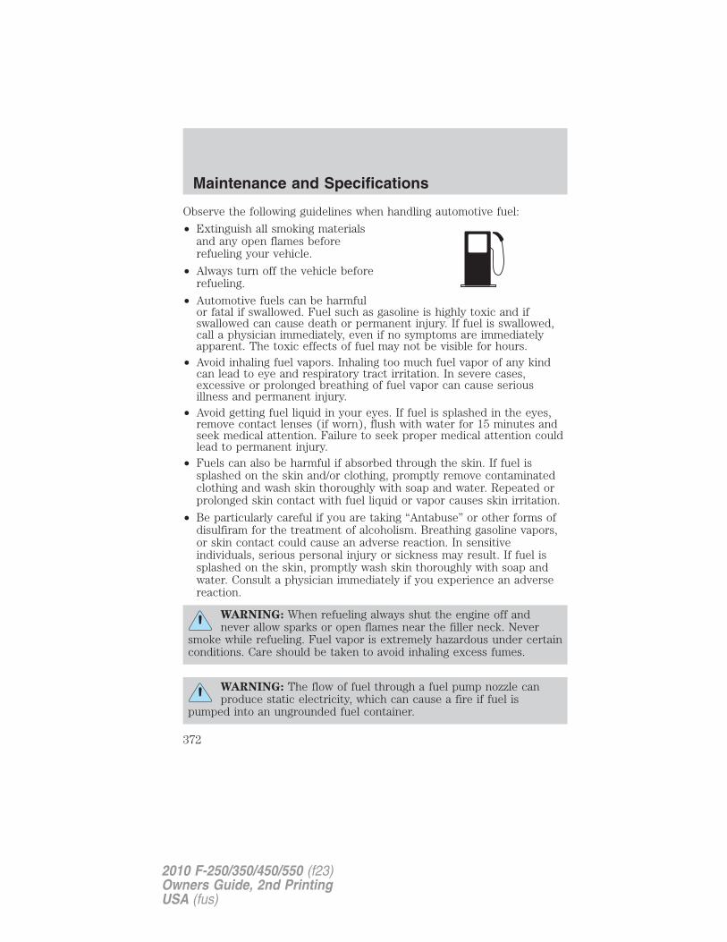
Observe the following guidelines when handling automotive fuel:
• Extinguish all smoking materialsand any open flames beforerefueling your vehicle.
• Always turn off the vehicle beforerefueling.
• Automotive fuels can be harmfulor fatal if swallowed. Fuel such as gasoline is highly toxic and ifswallowed can cause death or permanent injury. If fuel is swallowed,call a physician immediately, even if no symptoms are immediatelyapparent. The toxic effects of fuel may not be visible for hours.
• Avoid inhaling fuel vapors. Inhaling too much fuel vapor of any kindcan lead to eye and respiratory tract irritation. In severe cases,excessive or prolonged breathing of fuel vapor can cause seriousillness and permanent injury.
• Avoid getting fuel liquid in your eyes. If fuel is splashed in the eyes,remove contact lenses (if worn), flush with water for 15 minutes andseek medical attention. Failure to seek proper medical attention couldlead to permanent injury.
• Fuels can also be harmful if absorbed through the skin. If fuel issplashed on the skin and/or clothing, promptly remove contaminatedclothing and wash skin thoroughly with soap and water. Repeated orprolonged skin contact with fuel liquid or vapor causes skin irritation.
• Be particularly careful if you are taking “Antabuse” or other forms ofdisulfiram for the treatment of alcoholism. Breathing gasoline vapors,or skin contact could cause an adverse reaction. In sensitiveindividuals, serious personal injury or sickness may result. If fuel issplashed on the skin, promptly wash skin thoroughly with soap andwater. Consult a physician immediately if you experience an adversereaction.
WARNING: When refueling always shut the engine off andnever allow sparks or open flames near the filler neck. Never
smoke while refueling. Fuel vapor is extremely hazardous under certainconditions. Care should be taken to avoid inhaling excess fumes.
WARNING: The flow of fuel through a fuel pump nozzle canproduce static electricity, which can cause a fire if fuel is
pumped into an ungrounded fuel container.
Maintenance and Specifications
372
2010 F-250/350/450/550 (f23)Owners Guide, 2nd PrintingUSA (fus)
Refueling
WARNING: Fuel vapor burns violently and a fuel fire can causesevere injuries. To help avoid injuries to you and others:
• Read and follow all the instructions on the pump island;
• Turn off your engine when you are refueling;
• Do not smoke if you are near fuel or refueling your vehicle;
• Keep sparks, flames and smoking materials away from fuel;
• Stay outside your vehicle and do not leave the fuel pump unattendedwhen refueling your vehicle — this is against the law in some places;
• Keep children away from the fuel pump; never let children pumpfuel.
Use the following guidelines to avoid electrostatic charge build-up whenfilling an ungrounded fuel container:
• Place approved fuel container on the ground.
• DO NOT fill a fuel container while it is in the vehicle (including thecargo area).
• Keep the fuel pump nozzle in contact with the fuel container whilefilling.
• DO NOT use a device that would hold the fuel pump handle in the fillposition.
Fuel filler capWhen fueling your vehicle:
1. Turn the engine off.
2. Carefully turn the filler cap counterclockwise until it spins off.
3. Pull to remove the cap from the fuel filler pipe.
4. To install the cap, align the tabs on the cap with the notches on thefiller pipe.
5. Turn the filler cap clockwise until it clicks.
If the “Check Fuel Cap” indicator comes on and stays on after you startthe engine, the fuel filler cap may not be properly installed. Turn off theengine, remove the fuel filler cap, align the cap properly and reinstall it.
Maintenance and Specifications
373
2010 F-250/350/450/550 (f23)Owners Guide, 2nd PrintingUSA (fus)
If you must replace the fuel filler cap, replace it with a fuel fillercap that is designed for your vehicle. The vehicle warranty maybe void for any damage to the fuel tank or fuel system if thecorrect genuine Ford or Motorcraft� fuel filler cap is not used.
WARNING: The fuel system may be under pressure. If the fuelfiller cap is venting vapor or if you hear a hissing sound, wait
until it stops before completely removing the fuel filler cap. Otherwise,fuel may spray out and injure you or others.
WARNING: If you do not use the proper fuel filler cap,excessive pressure or vacuum in the fuel tank may damage the
fuel system or cause the fuel cap to disengage in a collision, which mayresult in possible personal injury.
Choosing the right fuel
Use only UNLEADED fuel or UNLEADED fuel blended with a maximumof 10% ethanol. Do not use fuel ethanol (E85), diesel, methanol, leadedfuel or any other fuel. The use of leaded fuel is prohibited by law andcould damage your vehicle.
Your vehicle was not designed to use fuel or fuel additives with metalliccompounds, including manganese-based additives.
Note: Use of any fuel other than those recommended may causepowertrain damage, a loss of vehicle performance, and repairs may notbe covered under warranty.
Maintenance and Specifications
374
2010 F-250/350/450/550 (f23)Owners Guide, 2nd PrintingUSA (fus)
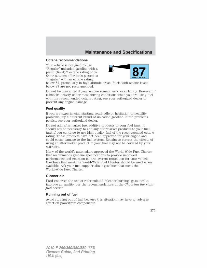
Octane recommendationsYour vehicle is designed to use“Regular” unleaded gasoline with apump (R+M)/2 octane rating of 87.Some stations offer fuels posted as“Regular” with an octane ratingbelow 87, particularly in high altitude areas. Fuels with octane levelsbelow 87 are not recommended.
Do not be concerned if your engine sometimes knocks lightly. However, ifit knocks heavily under most driving conditions while you are using fuelwith the recommended octane rating, see your authorized dealer toprevent any engine damage.
Fuel qualityIf you are experiencing starting, rough idle or hesitation driveabilityproblems, try a different brand of unleaded gasoline. If the problemspersist, see your authorized dealer.
Do not add aftermarket fuel additive products to your fuel tank. Itshould not be necessary to add any aftermarket products to your fueltank if you continue to use high quality fuel of the recommended octanerating. These products have not been approved for your engine andcould cause damage to the fuel system. Repairs to correct the effects ofusing an aftermarket product in your fuel may not be covered by yourwarranty.
Many of the world’s automakers approved the World-Wide Fuel Charterthat recommends gasoline specifications to provide improvedperformance and emission control system protection for your vehicle.Gasolines that meet the World-Wide Fuel Charter should be used whenavailable. Ask your fuel supplier about gasolines that meet theWorld-Wide Fuel Charter.
Cleaner airFord endorses the use of reformulated “cleaner-burning” gasolines toimprove air quality, per the recommendations in the Choosing the rightfuel section.
Running out of fuelAvoid running out of fuel because this situation may have an adverseeffect on powertrain components.
87(R+M)/2 METHOD
Maintenance and Specifications
375
2010 F-250/350/450/550 (f23)Owners Guide, 2nd PrintingUSA (fus)
If you have run out of fuel:• You may need to cycle the ignition from off to on several times after
refueling to allow the fuel system to pump the fuel from the tank tothe engine. On restarting, cranking time will take a few seconds longerthan normal.
• Normally, adding 1 gallon (3.8L) of fuel is enough to restart theengine. If the vehicle is out of fuel and on a steep grade, more than1 gallon (3.8L) may be required.
• The service engine soon indicator may come on. For moreinformation on the service engine soon indicator, refer toWarning lights and chimes in the Instrument Cluster chapter.
ESSENTIALS OF GOOD FUEL ECONOMY
Measuring techniquesYour best source of information about actual fuel economy is you, thedriver. You must gather information as accurately and consistently aspossible. Fuel expense, frequency of fill-ups or fuel gauge readings areNOT accurate as a measure of fuel economy. We do not recommendtaking fuel economy measurements during the first 1,000 miles(1,600 km) of driving (engine break-in period). You will get a moreaccurate measurement after 2,000 miles–3,000 miles (3,000 km–5,000km).
Filling the tankThe advertised fuel capacity of the fuel tank on your vehicle is equal tothe rated refill capacity of the fuel tank as listed in the Maintenanceproduct specifications and capacities section of this chapter.The advertised capacity is the amount of the indicated capacity and theempty reserve combined. Indicated capacity is the difference in theamount of fuel in a full tank and a tank when the fuel gauge indicatesempty. Empty reserve is the small amount of fuel remaining in the fueltank after the fuel gauge indicates empty.
The amount of usable fuel in the empty reserve varies and shouldnot be relied upon to increase driving range. When refueling yourvehicle after the fuel gauge indicates empty, you might not beable to refuel the full amount of the advertised capacity of thefuel tank due to the empty reserve still present in the tank.
For consistent results when filling the fuel tank:
• Turn the engine/ignition switch to the off position prior to refueling,an error in the reading will result if the engine is left running.
Maintenance and Specifications
376
2010 F-250/350/450/550 (f23)Owners Guide, 2nd PrintingUSA (fus)
• Use the same filling rate setting (low — medium — high) each timethe tank is filled.
• Allow no more than two automatic click-offs when filling.• Always use fuel with the recommended octane rating.• Use a known quality gasoline, preferably a national brand.• Use the same side of the same pump and have the vehicle facing the
same direction each time you fill up.• Have the vehicle loading and distribution the same every time.Your results will be most accurate if your filling method is consistent.
Calculating fuel economy1. Fill the fuel tank completely and record the initial odometer reading(in miles or kilometers).2. Each time you fill the tank, record the amount of fuel added (ingallons or liters).3. After at least three to five tank fill-ups, fill the fuel tank and recordthe current odometer reading.4. Subtract your initial odometer reading from the current odometerreading.5. Follow one of the simple calculations in order to determine fueleconomy:
Calculation 1: Divide total miles traveled by total gallons used.
Calculation 2: Multiply liters used by 100, then divide by totalkilometers traveled.
Keep a record for at least one month and record the type of driving (cityor highway). This will provide an accurate estimate of the vehicle’s fueleconomy under current driving conditions. Additionally, keeping recordsduring summer and winter will show how temperature impacts fueleconomy. In general, lower temperatures give lower fuel economy.
Driving style — good driving and fuel economy habitsGive consideration to the lists that follow and you may be able to changea number of variables and improve your fuel economy.
Habits• Smooth, moderate operation can yield up to 10% savings in fuel.
• Steady speeds without stopping will usually give the best fueleconomy.
Maintenance and Specifications
377
2010 F-250/350/450/550 (f23)Owners Guide, 2nd PrintingUSA (fus)
• Idling for long periods of time (greater than one minute) may wastefuel.
• Anticipate stopping; slowing down may eliminate the need to stop.• Sudden or hard accelerations may reduce fuel economy.• Slow down gradually.• Driving at reasonable speeds (traveling at 55 mph [88 km/h] uses 15%
less fuel than traveling at 65 mph [105 km/h]).• Revving the engine before turning it off may reduce fuel economy.• Using the air conditioner or defroster may reduce fuel economy.• You may want to turn off the speed control in hilly terrain if
unnecessary shifting between the top gears occurs. Unnecessaryshifting of this type could result in reduced fuel economy.
• Warming up a vehicle on cold mornings is not required and mayreduce fuel economy.
• Resting your foot on the brake pedal while driving may reduce fueleconomy.
• Combine errands and minimize stop-and-go driving.
Maintenance• Keep tires properly inflated and use only recommended size.• Operating a vehicle with the wheels out of alignment will reduce fuel
economy.• Use recommended engine oil. Refer to Maintenance product
specifications and capacities in this chapter.
• Perform all regularly scheduled maintenance items. Follow therecommended maintenance schedule and owner maintenance checksfound in scheduled maintenance information.
Conditions• Heavily loading a vehicle or towing a trailer may reduce fuel economy
at any speed.
• Carrying unnecessary weight may reduce fuel economy (approximately1 mpg [0.4 km/L] is lost for every 400 lb [180 kg] of weight carried).
• Adding certain accessories to your vehicle (for example bugdeflectors, rollbars/light bars, running boards, ski/luggage racks) mayreduce fuel economy.
• To maximize the fuel economy, drive with the tonneau cover installed(if equipped).
Maintenance and Specifications
378
2010 F-250/350/450/550 (f23)Owners Guide, 2nd PrintingUSA (fus)
• Using fuel blended with alcohol may lower fuel economy.• Fuel economy may decrease with lower temperatures during the first
8–10 miles (12–16 km) of driving.• Driving on flat terrain offers improved fuel economy as compared to
driving on hilly terrain.• Transmissions give their best fuel economy when operated in the top
cruise gear and with steady pressure on the gas pedal.• Four-wheel-drive operation (if equipped) is less fuel efficient than
two-wheel-drive operation.
• Close windows for high speed driving.
EPA fuel economy estimatesIf applicable, every new vehicle should have a sticker on the windowcalled the Monroney Label which contains EPA fuel economy estimates.Contact your authorized dealer if the Monroney Label is not suppliedwith your vehicle. The EPA fuel economy estimates should be your guidefor the fuel economy comparisons with other vehicles. Your fuel economymay vary depending upon the method of operation and conditions.
EMISSION CONTROL SYSTEM
Your vehicle is equipped with various emission control components and acatalytic converter which will enable your vehicle to comply withapplicable exhaust emission standards. To make sure that the catalyticconverter and other emission control components continue to workproperly:
• Use only the specified fuel listed.
• Avoid running out of fuel.
• Do not turn off the ignition while your vehicle is moving, especially athigh speeds.
• Have the items listed in scheduled maintenance informationperformed according to the specified schedule.
The scheduled maintenance items listed in scheduled maintenanceinformation are essential to the life and performance of your vehicleand to its emissions system.
If other than Ford, Motorcraft� or Ford-authorized parts are used formaintenance replacements or for service of components affectingemission control, such non-Ford parts should be equivalent to genuineFord Motor Company parts in performance and durability.
Maintenance and Specifications
379
2010 F-250/350/450/550 (f23)Owners Guide, 2nd PrintingUSA (fus)
WARNING: Do not park, idle, or drive your vehicle in dry grassor other dry ground cover. The emission system heats up the
engine compartment and exhaust system, which can start a fire.
Illumination of the service engine soon indicator, charging systemwarning light or the temperature warning light, fluid leaks, strange odors,smoke or loss of engine power could indicate that the emission controlsystem is not working properly.
An improperly operating or damaged exhaust system may allow exhaustto enter the vehicle. Have a damaged or improperly operating exhaustsystem inspected and repaired immediately.
WARNING: Exhaust leaks may result in entry of harmful andpotentially lethal fumes into the passenger compartment.
Do not make any unauthorized changes to your vehicle or engine. Bylaw, vehicle owners and anyone who manufactures, repairs, services,sells, leases, trades vehicles, or supervises a fleet of vehicles are notpermitted to intentionally remove an emission control device or preventit from working. Information about your vehicle’s emission system is onthe Vehicle Emission Control Information Decal located on or near theengine. This decal also lists engine displacement.
Please consult your Warranty Guide/Customer Information Guide forcomplete emission warranty information.
On board diagnostics (OBD-II)Your vehicle is equipped with a computer that monitors the engine’semission control system. This system is commonly known as the OnBoard Diagnostics System (OBD-II). The OBD-II system protects theenvironment by ensuring that your vehicle continues to meetgovernment emission standards. The OBD-II system also assists yourauthorized dealer in properly servicing your vehicle. When the serviceengine soon indicator illuminates, the OBD-II system has detecteda malfunction. Temporary malfunctions may cause the service enginesoon indicator to illuminate. Examples are:
1. The vehicle has run out of fuel—the engine may misfire or run poorly.
2. Poor fuel quality or water in the fuel—the engine may misfire or runpoorly.
Maintenance and Specifications
380
2010 F-250/350/450/550 (f23)Owners Guide, 2nd PrintingUSA (fus)
3. The fuel cap may not have been securely tightened. See Fuel fillercap in this chapter.
4. Driving through deep water—the electrical system may be wet.
These temporary malfunctions can be corrected by filling the fuel tankwith good quality fuel, properly tightening the fuel cap or letting theelectrical system dry out. After three driving cycles without these or anyother temporary malfunctions present, the service engine soonindicator should stay off the next time the engine is started. A drivingcycle consists of a cold engine startup followed by mixed city/highwaydriving. No additional vehicle service is required.
If the service engine soon indicator remains on, have your vehicleserviced at the first available opportunity. Although some malfunctionsdetected by the OBD-II may not have symptoms that are apparent,continued driving with the service engine soon indicator on canresult in increased emissions, lower fuel economy, reduced engine andtransmission smoothness, and lead to more costly repairs.
Readiness for Inspection/Maintenance (I/M) testingSome state/provincial and local governments may haveInspection/Maintenance (I/M) programs to inspect the emission controlequipment on your vehicle. Failure to pass this inspection could preventyou from getting a vehicle registration. Your vehicle may not pass the I/Mtest if the service engine soon indicator is on or not workingproperly (bulb is burned out), or if the OBD-II system has determinedthat some of the emission control systems have not been properlychecked. In this case, the vehicle is considered not ready for I/M testing.
If the service engine soon indicator is on or the bulb does notwork, the vehicle may need to be serviced. Refer to the On boarddiagnostics (OBD-II) description in this chapter.
If the vehicle’s engine or transmission has just been serviced, or thebattery has recently run down or been replaced, the OBD-II system mayindicate that the vehicle is not ready for I/M testing. To determine if thevehicle is ready for I/M testing, turn the ignition key to the on positionfor 15 seconds without cranking the engine. If the service enginesoon indicator blinks eight times, it means that the vehicle is notready for I/M testing; if the service engine soon indicator stays onsolid, it means that the vehicle is ready for I/M testing.
Maintenance and Specifications
381
2010 F-250/350/450/550 (f23)Owners Guide, 2nd PrintingUSA (fus)
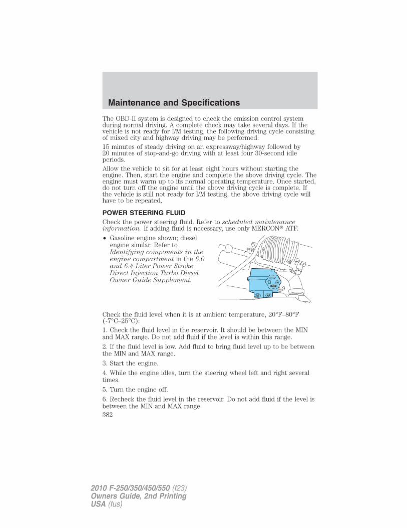
The OBD-II system is designed to check the emission control systemduring normal driving. A complete check may take several days. If thevehicle is not ready for I/M testing, the following driving cycle consistingof mixed city and highway driving may be performed:15 minutes of steady driving on an expressway/highway followed by20 minutes of stop-and-go driving with at least four 30-second idleperiods.Allow the vehicle to sit for at least eight hours without starting theengine. Then, start the engine and complete the above driving cycle. Theengine must warm up to its normal operating temperature. Once started,do not turn off the engine until the above driving cycle is complete. Ifthe vehicle is still not ready for I/M testing, the above driving cycle willhave to be repeated.
POWER STEERING FLUIDCheck the power steering fluid. Refer to scheduled maintenanceinformation. If adding fluid is necessary, use only MERCON� ATF.
• Gasoline engine shown; dieselengine similar. Refer toIdentifying components in theengine compartment in the 6.0and 6.4 Liter Power StrokeDirect Injection Turbo DieselOwner Guide Supplement.
Check the fluid level when it is at ambient temperature, 20°F–80°F(-7°C–25°C):1. Check the fluid level in the reservoir. It should be between the MINand MAX range. Do not add fluid if the level is within this range.
2. If the fluid level is low. Add fluid to bring fluid level up to be betweenthe MIN and MAX range.
3. Start the engine.
4. While the engine idles, turn the steering wheel left and right severaltimes.
5. Turn the engine off.
6. Recheck the fluid level in the reservoir. Do not add fluid if the level isbetween the MIN and MAX range.
Maintenance and Specifications
382
2010 F-250/350/450/550 (f23)Owners Guide, 2nd PrintingUSA (fus)
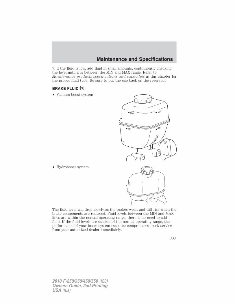
7. If the fluid is low, add fluid in small amounts, continuously checkingthe level until it is between the MIN and MAX range. Refer toMaintenance products specifications and capacities in this chapter forthe proper fluid type. Be sure to put the cap back on the reservoir.
BRAKE FLUID
• Vacuum boost system
• Hydroboost system
The fluid level will drop slowly as the brakes wear, and will rise when thebrake components are replaced. Fluid levels between the MIN and MAXlines are within the normal operating range; there is no need to addfluid. If the fluid levels are outside of the normal operating range, theperformance of your brake system could be compromised; seek servicefrom your authorized dealer immediately.
Maintenance and Specifications
383
2010 F-250/350/450/550 (f23)Owners Guide, 2nd PrintingUSA (fus)
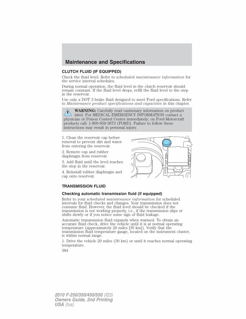
CLUTCH FLUID (IF EQUIPPED)Check the fluid level. Refer to scheduled maintenance information forthe service interval schedules.During normal operation, the fluid level in the clutch reservoir shouldremain constant. If the fluid level drops, refill the fluid level to the stepin the reservoir.Use only a DOT 3 brake fluid designed to meet Ford specifications. Referto Maintenance product specifications and capacities in this chapter.
WARNING: Carefully read cautionary information on productlabel. For MEDICAL EMERGENCY INFORMATION contact a
physician or Poison Control Center immediately; on Ford-Motorcraftproducts call: 1-800-959-3673 (FORD). Failure to follow theseinstructions may result in personal injury.
1. Clean the reservoir cap beforeremoval to prevent dirt and waterfrom entering the reservoir.
2. Remove cap and rubberdiaphragm from reservoir.
3. Add fluid until the level reachesthe step in the reservoir.
4. Reinstall rubber diaphragm andcap onto reservoir.
TRANSMISSION FLUID
Checking automatic transmission fluid (if equipped)Refer to your scheduled maintenance information for scheduledintervals for fluid checks and changes. Your transmission does notconsume fluid. However, the fluid level should be checked if thetransmission is not working properly, i.e., if the transmission slips orshifts slowly or if you notice some sign of fluid leakage.Automatic transmission fluid expands when warmed. To obtain anaccurate fluid check, drive the vehicle until it is at normal operatingtemperature (approximately 20 miles [30 km]). Verify that thetransmission fluid temperature gauge, located on the instrument cluster,is within normal range.1. Drive the vehicle 20 miles (30 km) or until it reaches normal operatingtemperature.
Maintenance and Specifications
384
2010 F-250/350/450/550 (f23)Owners Guide, 2nd PrintingUSA (fus)
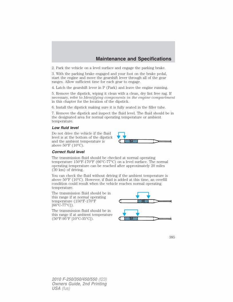
2. Park the vehicle on a level surface and engage the parking brake.
3. With the parking brake engaged and your foot on the brake pedal,start the engine and move the gearshift lever through all of the gearranges. Allow sufficient time for each gear to engage.
4. Latch the gearshift lever in P (Park) and leave the engine running.
5. Remove the dipstick, wiping it clean with a clean, dry lint free rag. Ifnecessary, refer to Identifying components in the engine compartmentin this chapter for the location of the dipstick.
6. Install the dipstick making sure it is fully seated in the filler tube.
7. Remove the dipstick and inspect the fluid level. The fluid should be inthe designated area for normal operating temperature or ambienttemperature.
Low fluid levelDo not drive the vehicle if the fluidlevel is at the bottom of the dipstickand the ambient temperature isabove 50°F (10°C).
Correct fluid level
The transmission fluid should be checked at normal operatingtemperature 150°F-170°F (66°C-77°C) on a level surface. The normaloperating temperature can be reached after approximately 20 miles(30 km) of driving.
You can check the fluid without driving if the ambient temperature isabove 50°F (10°C). However, if fluid is added at this time, an overfillcondition could result when the vehicle reaches normal operatingtemperature.
The transmission fluid should be inthis range if at normal operatingtemperature (150°F-170°F[66°C-77°C]).
The transmission fluid should be inthis range if at ambient temperature(50°F-95°F [10°C-35°C]).
Maintenance and Specifications
385
2010 F-250/350/450/550 (f23)Owners Guide, 2nd PrintingUSA (fus)
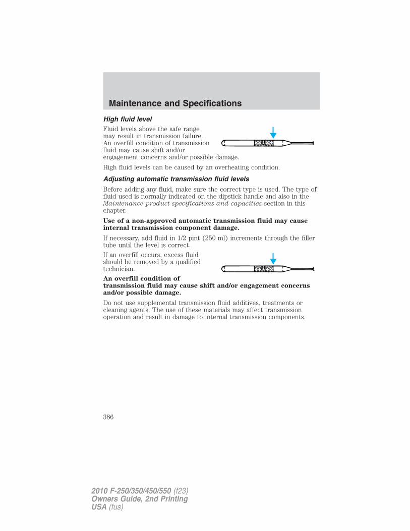
High fluid levelFluid levels above the safe rangemay result in transmission failure.An overfill condition of transmissionfluid may cause shift and/orengagement concerns and/or possible damage.
High fluid levels can be caused by an overheating condition.
Adjusting automatic transmission fluid levels
Before adding any fluid, make sure the correct type is used. The type offluid used is normally indicated on the dipstick handle and also in theMaintenance product specifications and capacities section in thischapter.
Use of a non-approved automatic transmission fluid may causeinternal transmission component damage.
If necessary, add fluid in 1/2 pint (250 ml) increments through the fillertube until the level is correct.
If an overfill occurs, excess fluidshould be removed by a qualifiedtechnician.
An overfill condition oftransmission fluid may cause shift and/or engagement concernsand/or possible damage.
Do not use supplemental transmission fluid additives, treatments orcleaning agents. The use of these materials may affect transmissionoperation and result in damage to internal transmission components.
Maintenance and Specifications
386
2010 F-250/350/450/550 (f23)Owners Guide, 2nd PrintingUSA (fus)
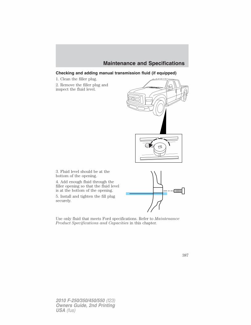
Checking and adding manual transmission fluid (if equipped)1. Clean the filler plug.
2. Remove the filler plug andinspect the fluid level.
3. Fluid level should be at thebottom of the opening.
4. Add enough fluid through thefiller opening so that the fluid levelis at the bottom of the opening.
5. Install and tighten the fill plugsecurely.
Use only fluid that meets Ford specifications. Refer to MaintenanceProduct Specifications and Capacities in this chapter.
Maintenance and Specifications
387
2010 F-250/350/450/550 (f23)Owners Guide, 2nd PrintingUSA (fus)
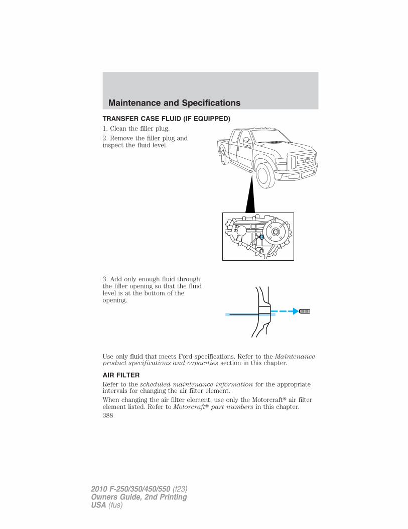
TRANSFER CASE FLUID (IF EQUIPPED)1. Clean the filler plug.
2. Remove the filler plug andinspect the fluid level.
3. Add only enough fluid throughthe filler opening so that the fluidlevel is at the bottom of theopening.
Use only fluid that meets Ford specifications. Refer to the Maintenanceproduct specifications and capacities section in this chapter.
AIR FILTERRefer to the scheduled maintenance information for the appropriateintervals for changing the air filter element.When changing the air filter element, use only the Motorcraft� air filterelement listed. Refer to Motorcraft� part numbers in this chapter.
Maintenance and Specifications
388
2010 F-250/350/450/550 (f23)Owners Guide, 2nd PrintingUSA (fus)
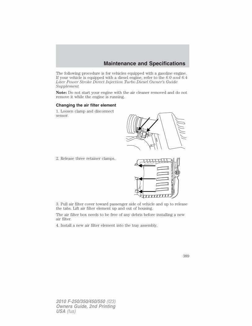
The following procedure is for vehicles equipped with a gasoline engine.If your vehicle is equipped with a diesel engine, refer to the 6.0 and 6.4Liter Power Stroke Direct Injection Turbo Diesel Owner’s GuideSupplement.
Note: Do not start your engine with the air cleaner removed and do notremove it while the engine is running.
Changing the air filter element1. Loosen clamp and disconnectsensor.
2. Release three retainer clamps.
3. Pull air filter cover toward passenger side of vehicle and up to releasethe tabs. Lift air filter element up and out of housing.
The air filter box needs to be free of any debris before installing a newair filter.
4. Install a new air filter element into the tray assembly.
Maintenance and Specifications
389
2010 F-250/350/450/550 (f23)Owners Guide, 2nd PrintingUSA (fus)

5. Return air filter cover to originalposition making sure the four tabsare engaged and secure the threeclamps. Tighten clamp on air tubeand reconnect sensor.
MOTORCRAFT PART NUMBERS
Component 5.4L V8/6.8L V10 engines
Air filter element FA-1883Fuel filter FG-1083Oil filter FL-820-SBattery (standard) BXT-65-650Battery (optional) BXT-65-750Spark plugs-platinum 1
Remote automatic transmission filter 2, 3
1For spark plug replacement, see your authorized dealer. Refer to thescheduled maintenance information for the appropriate intervals forchanging the spark plugs.
Replace the spark plugs with ones that meet Ford material anddesign specifications for your vehicle, such as Motorcraft� orequivalent replacement parts. The customer warranty may bevoid for any damage to the engine if such spark plugs are notused.2Also available with 6.4L diesel engine and TorqShift� transmission. Partnumber is FT-176.3Also available with 6.4L diesel engine and TorqShift� transmission. Partnumber is FT-175.
Maintenance and Specifications
390
2010 F-250/350/450/550 (f23)Owners Guide, 2nd PrintingUSA (fus)
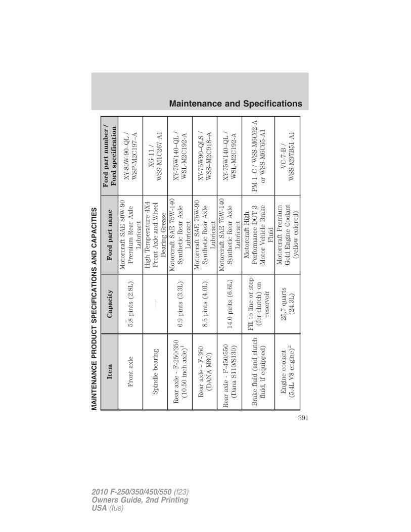
MA
INT
EN
AN
CE
PR
OD
UC
TS
PE
CIF
ICA
TIO
NS
AN
DC
AP
AC
ITIE
S
Item
Cap
acit
yF
ord
part
nam
eF
ord
part
nu
mb
er
/
Fo
rd
sp
ecif
icati
on
Fro
ntax
le5.
8pi
nts
(2.8
L)
Mot
orcr
aft
SAE
80W
-90
Pre
miu
mR
ear
Axl
eL
ubri
cant
XY-
80W
-90–
QL
/W
SP-M
2C19
7–A
Spin
dle
bear
ing
—H
igh
Tem
pera
ture
4X4
Fro
ntA
xle
and
Whe
elB
eari
ngG
reas
e
XG
-11
/W
SS-M
1C26
7-A
1
Rea
rax
le-
F-2
50/3
50(1
0.50
inch
axle
)16.
9pi
nts
(3.3
L)
Mot
orcr
aft
SAE
75W
-140
Synt
heti
cR
ear
Axl
eL
ubri
cant
XY-
75W
140–
QL
/W
SL-M
2C19
2-A
Rea
rax
le-
F-3
50(D
AN
AM
80)
8.5
pint
s(4
.0L
)M
otor
craf
tSA
E75
W-9
0Sy
nthe
tic
Rea
rA
xle
Lub
rica
nt
XY-
75W
90–Q
LS
/W
SS–M
2C91
8–A
Rea
rax
le-
F-4
50/5
50(D
ana
S110
/S13
0)14
.0pi
nts
(6.6
L)
Mot
orcr
aft
SAE
75W
-140
Synt
heti
cR
ear
Axl
eL
ubri
cant
XY-
75W
140–
QL
/W
SL-M
2C19
2-A
Bra
kefl
uid
(and
clut
chfl
uid,
ifeq
uipp
ed)
Fill
tolin
eor
step
(for
clut
ch)
onre
serv
oir
Mot
orcr
aft
Hig
hP
erfo
rman
ceD
OT
3M
otor
Veh
icle
Bra
keF
luid
PM
-1–C
/W
SS-M
6C62
-Aor
WSS
-M6C
65-A
1
Eng
ine
cool
ant
(5.4
LV
8en
gine
)225
.7qu
arts
(24.
3L)
Mot
orcr
aft
Pre
miu
mG
old
Eng
ine
Coo
lant
(yel
low
-col
ored
)
VC
-7-B
/W
SS-M
97B
51-A
1
Maintenance and Specifications
391
2010 F-250/350/450/550 (f23)Owners Guide, 2nd PrintingUSA (fus)
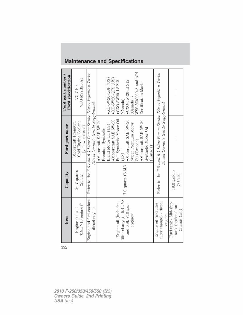
Item
Cap
acit
yF
ord
part
nam
eF
ord
part
nu
mb
er
/
Fo
rd
sp
ecif
icati
on
Eng
ine
cool
ant
(6.8
LV
10en
gine
)226
.7qu
arts
(25.
3L)
Mot
orcr
aft
Pre
miu
mG
old
Eng
ine
Coo
lant
(yel
low
-col
ored
)
VC
-7-B
/W
SS-M
97B
51-A
1
Eng
ine
and
fuel
cool
ant
-di
esel
engi
neR
efer
toth
e6
.0a
nd
6.4
Lit
er
Pow
er
Str
oke
Dir
ect
Inje
cti
on
Tu
rbo
Die
sel
Ow
ner’s
Gu
ide
Su
pp
lem
en
t
Eng
ine
oil
(inc
lude
sfi
lter
chan
ge)
-5.
4LV
8an
d6.
8LV
10ga
sen
gine
s6
7.0
quar
ts(6
.6L
)
•Mot
orcr
aft
SAE
5W-2
0P
rem
ium
Synt
heti
cB
lend
Mot
orO
il(U
S)•M
otor
craf
tSA
E5W
-20
Ful
lSy
nthe
tic
Mot
orO
il(U
S)•M
otor
craf
tSA
E5W
-20
Supe
rP
rem
ium
Mot
orO
il(C
anad
a)•M
otor
craf
tSA
E5W
-20
Synt
heti
cM
otor
Oil
(Can
ada)
•XO
-5W
20-Q
SP(U
S)•X
O-5
W20
-QF
S(U
S)•C
XO
-5W
20–L
SP12
(Can
ada)
•CX
O-5
W-2
0-L
FS1
2(C
anad
a)/
WSS
-M2C
930-
Aan
dA
PI
Cer
tifi
cati
onM
ark
Eng
ine
oil
(inc
lude
sfi
lter
chan
ge)
-di
esel
engi
ne
Ref
erto
the
6.0
an
d6
.4L
iter
Pow
er
Str
oke
Dir
ect
Inje
cti
on
Tu
rbo
Die
sel
Ow
ner’s
Gu
ide
Su
pp
lem
en
t
Fue
lta
nk-
Mid
-shi
pta
nk(o
ptio
nal
onC
hass
isC
ab)
19.0
gallo
ns(7
1.9L
)—
—
Maintenance and Specifications
392
2010 F-250/350/450/550 (f23)Owners Guide, 2nd PrintingUSA (fus)
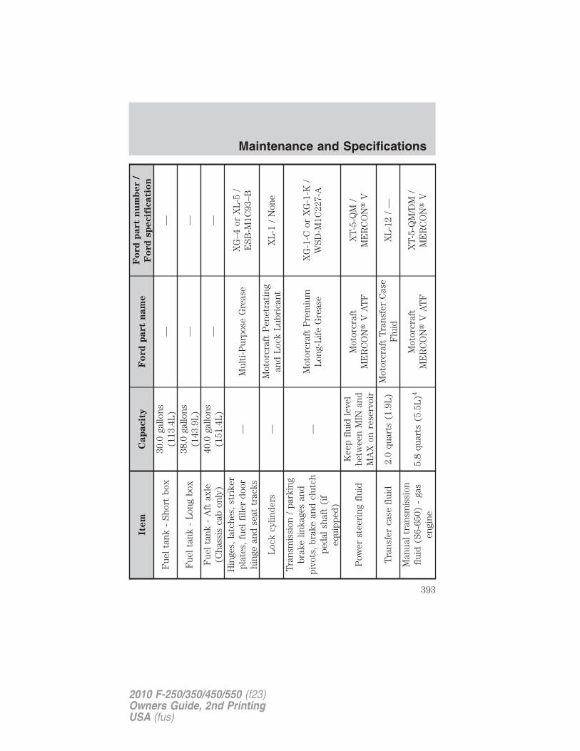
Item
Cap
acit
yF
ord
part
nam
eF
ord
part
nu
mb
er
/
Fo
rd
sp
ecif
icati
on
Fue
lta
nk-
Shor
tbo
x30
.0ga
llons
(113
.4L
)—
—
Fue
lta
nk-
Lon
gbo
x38
.0ga
llons
(143
.9L
)—
—
Fue
lta
nk-
Aft
axle
(Cha
ssis
cab
only
)40
.0ga
llons
(151
.4L
)—
—
Hin
ges,
latc
hes,
stri
ker
plat
es,
fuel
fille
rdo
orhi
nge
and
seat
trac
ks—
Mul
ti-P
urpo
seG
reas
eX
G–4
orX
L-5
/E
SB-M
1C93
–B
Loc
kcy
linde
rs—
Mot
orcr
aft
Pen
etra
ting
and
Loc
kL
ubri
cant
XL
-1/
Non
e
Tra
nsm
issi
on/
park
ing
brak
elin
kage
san
dpi
vots
,br
ake
and
clut
chpe
dal
shaf
t(i
feq
uipp
ed)
—M
otor
craf
tP
rem
ium
Lon
g-L
ife
Gre
ase
XG
-1-C
orX
G-1
-K/
WSD
-M1C
227-
A
Pow
erst
eeri
ngfl
uid
Kee
pfl
uid
leve
lbe
twee
nM
INan
dM
AX
onre
serv
oir
Mot
orcr
aft
ME
RC
ON
�V
AT
FX
T-5-
QM
/M
ER
CO
N�
V
Tra
nsfe
rca
sefl
uid
2.0
quar
ts(1
.9L
)M
otor
craf
tT
rans
fer
Cas
eF
luid
XL
-12
/—
Man
ual
tran
smis
sion
flui
d(S
6-65
0)-
gas
engi
ne5.
8qu
arts
(5.5
L)4
Mot
orcr
aft
ME
RC
ON
�V
AT
FX
T-5-
QM
/DM
/M
ER
CO
N�
V
Maintenance and Specifications
393
2010 F-250/350/450/550 (f23)Owners Guide, 2nd PrintingUSA (fus)
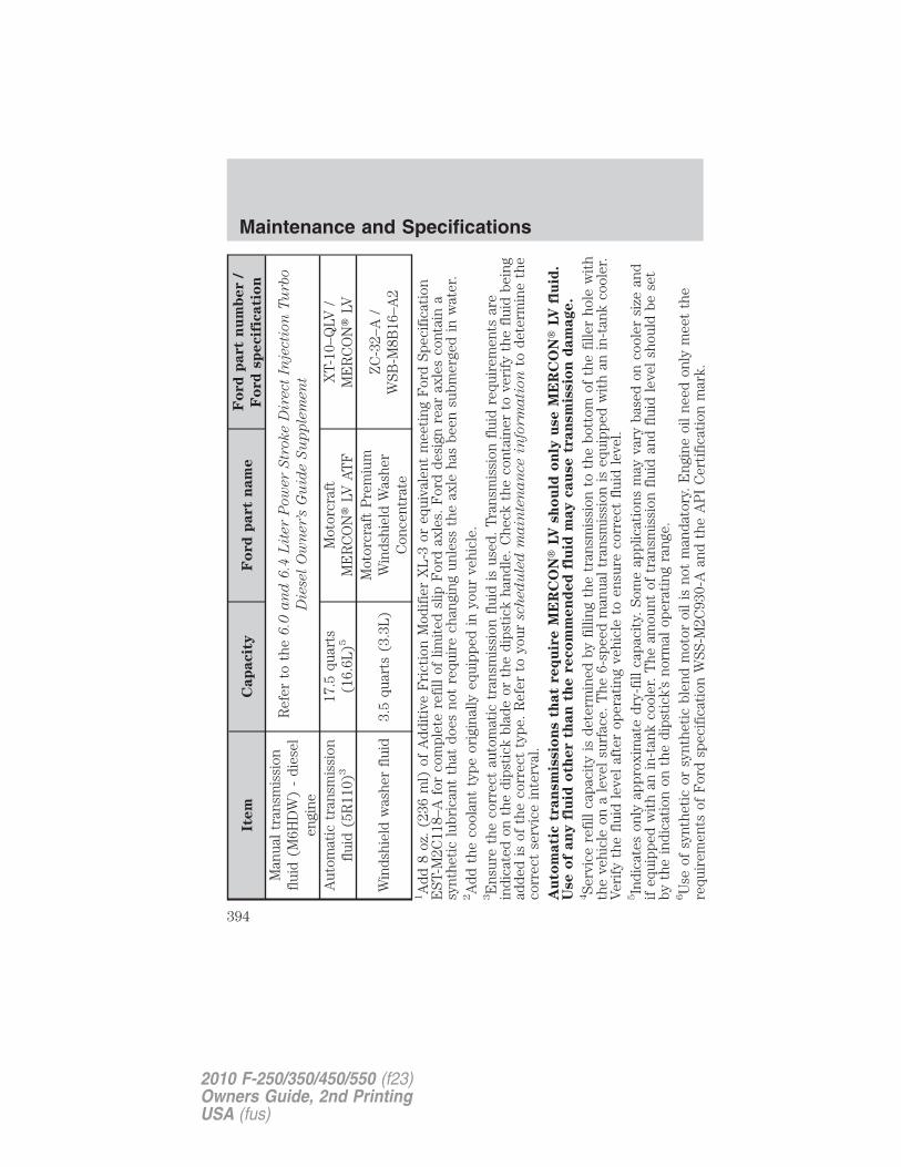
Item
Cap
acit
yF
ord
part
nam
eF
ord
part
nu
mb
er
/
Fo
rd
sp
ecif
icati
on
Man
ual
tran
smis
sion
flui
d(M
6HD
W)
-di
esel
engi
ne
Ref
erto
the
6.0
an
d6
.4L
iter
Pow
er
Str
oke
Dir
ect
Inje
cti
on
Tu
rbo
Die
sel
Ow
ner’s
Gu
ide
Su
pp
lem
en
t
Aut
omat
ictr
ansm
issi
onfl
uid
(5R
110)
317
.5qu
arts
(16.
6L)5
Mot
orcr
aft
ME
RC
ON
�LV
AT
FX
T-10
–QLV
/M
ER
CO
N�
LV
Win
dshi
eld
was
her
flui
d3.
5qu
arts
(3.3
L)
Mot
orcr
aft
Pre
miu
mW
inds
hiel
dW
ashe
rC
once
ntra
te
ZC
-32–
A/
WSB
-M8B
16–A
2
1A
dd8
oz.
(236
ml)
ofA
ddit
ive
Fri
ctio
nM
odif
ier
XL
-3or
equi
vale
ntm
eeti
ngF
ord
Spec
ific
atio
nE
ST-M
2C11
8–A
for
com
plet
ere
fill
oflim
ited
slip
For
dax
les.
For
dde
sign
rear
axle
sco
ntai
na
synt
heti
clu
bric
ant
that
does
not
requ
ire
chan
ging
unle
ssth
eax
leha
sbe
ensu
bmer
ged
inw
ater
.2A
ddth
eco
olan
tty
peor
igin
ally
equi
pped
inyo
urve
hicl
e.3E
nsur
eth
eco
rrec
tau
tom
atic
tran
smis
sion
flui
dis
used
.T
rans
mis
sion
flui
dre
quir
emen
tsar
ein
dica
ted
onth
edi
psti
ckbl
ade
orth
edi
psti
ckha
ndle
.C
heck
the
cont
aine
rto
veri
fyth
efl
uid
bein
gad
ded
isof
the
corr
ect
type
.R
efer
toyo
ursch
ed
ule
dm
ain
ten
an
ce
info
rm
ati
on
tode
term
ine
the
corr
ect
serv
ice
inte
rval
.A
uto
mati
ctr
an
sm
issio
ns
that
req
uir
eM
ER
CO
N�
LV
sh
ou
ldo
nly
use
ME
RC
ON
�LV
flu
id.
Use
of
an
yfl
uid
oth
er
than
the
reco
mm
en
ded
flu
idm
ay
cau
se
tran
sm
issio
nd
am
age.
4Se
rvic
ere
fill
capa
city
isde
term
ined
byfi
lling
the
tran
smis
sion
toth
ebo
ttom
ofth
efi
ller
hole
wit
hth
eve
hicl
eon
ale
vel
surf
ace.
The
6-sp
eed
man
ual
tran
smis
sion
iseq
uipp
edw
ith
anin
-tan
kco
oler
.V
erif
yth
efl
uid
leve
laf
ter
oper
atin
gve
hicl
eto
ensu
reco
rrec
tfl
uid
leve
l.5In
dica
tes
only
appr
oxim
ate
dry-
fill
capa
city
.So
me
appl
icat
ions
may
vary
base
don
cool
ersi
zean
dif
equi
pped
wit
han
in-t
ank
cool
er.
The
amou
ntof
tran
smis
sion
flui
dan
dfl
uid
leve
lsh
ould
bese
tby
the
indi
cati
onon
the
dips
tick
’sno
rmal
oper
atin
gra
nge.
6U
seof
synt
heti
cor
synt
heti
cbl
end
mot
oroi
lis
not
man
dato
ry.
Eng
ine
oil
need
only
mee
tth
ere
quir
emen
tsof
For
dsp
ecif
icat
ion
WSS
-M2C
930-
Aan
dth
eA
PI
Cer
tifi
cati
onm
ark.
Maintenance and Specifications
394
2010 F-250/350/450/550 (f23)Owners Guide, 2nd PrintingUSA (fus)
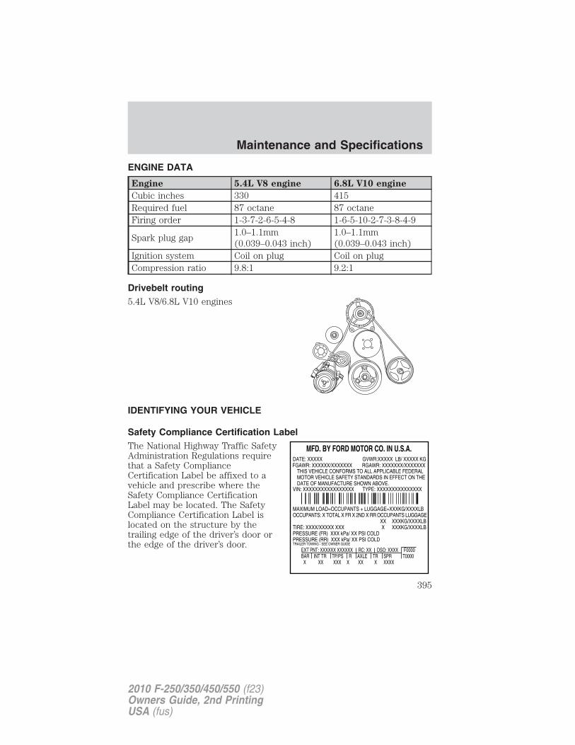
ENGINE DATA
Engine 5.4L V8 engine 6.8L V10 engine
Cubic inches 330 415Required fuel 87 octane 87 octaneFiring order 1-3-7-2-6-5-4-8 1-6-5-10-2-7-3-8-4-9
Spark plug gap1.0–1.1mm(0.039–0.043 inch)
1.0–1.1mm(0.039–0.043 inch)
Ignition system Coil on plug Coil on plugCompression ratio 9.8:1 9.2:1
Drivebelt routing5.4L V8/6.8L V10 engines
IDENTIFYING YOUR VEHICLE
Safety Compliance Certification LabelThe National Highway Traffic SafetyAdministration Regulations requirethat a Safety ComplianceCertification Label be affixed to avehicle and prescribe where theSafety Compliance CertificationLabel may be located. The SafetyCompliance Certification Label islocated on the structure by thetrailing edge of the driver’s door orthe edge of the driver’s door.
Maintenance and Specifications
395
2010 F-250/350/450/550 (f23)Owners Guide, 2nd PrintingUSA (fus)
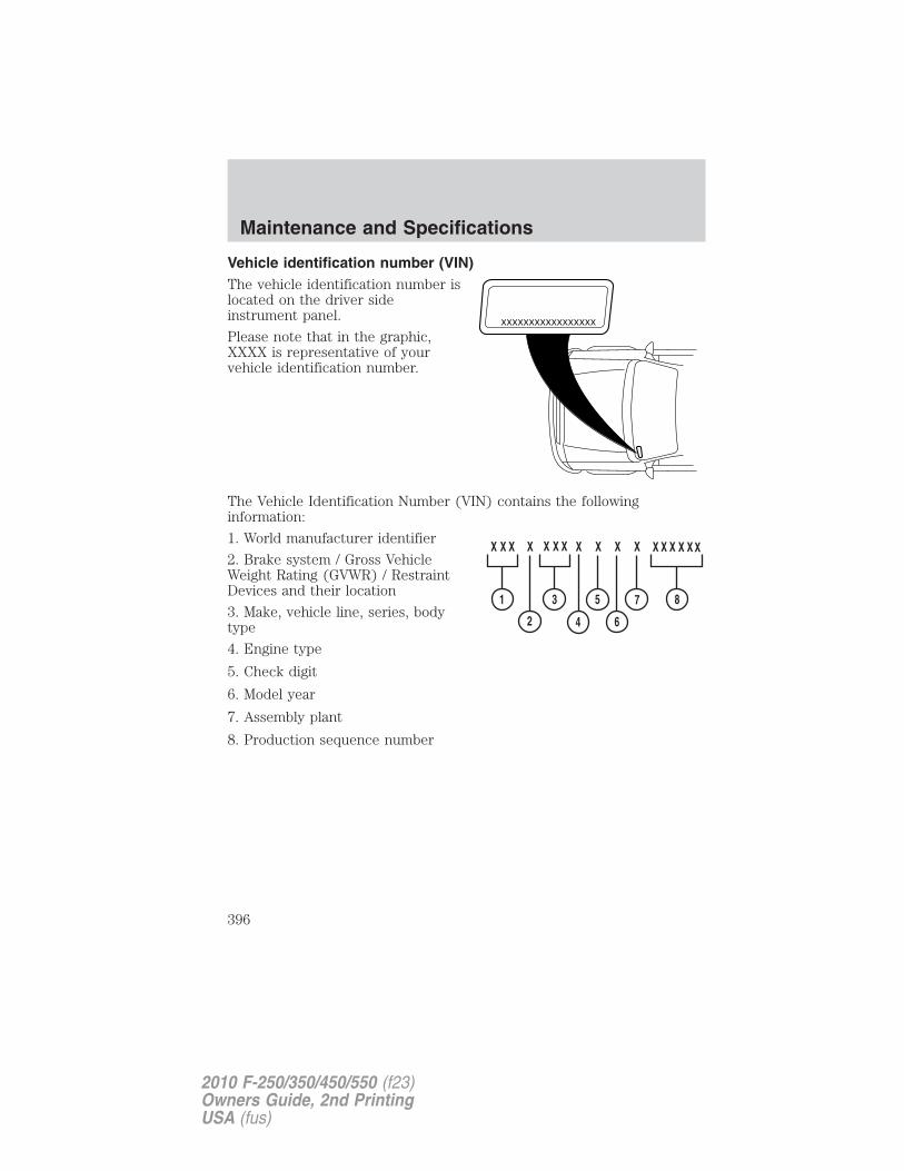
Vehicle identification number (VIN)The vehicle identification number islocated on the driver sideinstrument panel.
Please note that in the graphic,XXXX is representative of yourvehicle identification number.
The Vehicle Identification Number (VIN) contains the followinginformation:
1. World manufacturer identifier
2. Brake system / Gross VehicleWeight Rating (GVWR) / RestraintDevices and their location
3. Make, vehicle line, series, bodytype
4. Engine type
5. Check digit
6. Model year
7. Assembly plant
8. Production sequence number
XXXXXXXXXXXXXXXXX
Maintenance and Specifications
396
2010 F-250/350/450/550 (f23)Owners Guide, 2nd PrintingUSA (fus)
TRANSMISSION CODE DESIGNATIONSYou can find a transmission code onthe Safety Compliance CertificationLabel. The following table tells youwhich transmission each coderepresents.
Code Description
5 Six-speed manual, Dana (ZF S6–650)7 Six-speed manual, Dana (Z/F M6HD-W)T Five-speed automatic, TorqShift (gas engines)
BFive-speed automatic, TorqShift (dieselengine)
Maintenance and Specifications
397
2010 F-250/350/450/550 (f23)Owners Guide, 2nd PrintingUSA (fus)
GENUINE FORD ACCESSORIES FOR YOUR VEHICLEA wide selection of Genuine Ford Accessories are available for yourvehicle through your local Ford or Ford of Canada dealer. These qualityaccessories have been specifically engineered to fulfill your automotiveneeds; they are custom designed to complement the style andaerodynamic appearance of your vehicle. In addition, each accessory ismade from high quality materials and meets or exceeds Ford’s rigorousengineering and safety specifications. Ford Motor Company will repair orreplace any properly dealer-installed Genuine Ford Accessories found tobe defective in factory-supplied materials or workmanship during thewarranty period, as well as any component damaged by the defectiveaccessories. The accessories will be warranted for whichever providesyou the greatest benefit:
• 12 months or 12,000 miles (20,000 km) (whichever occurs first), or
• the remainder of your new vehicle limited warranty.
Contact your dealer for details and a copy of the warranty.
The following is a list of several Genuine Ford Accessories. Not allaccessories are available for all models. For a complete listing of theaccessories that are available for your vehicle, please contact your dealeror visit our online store at: www.fordaccessories.com.
Exterior styleBug shields
Chrome exhaust tips
Deflectors
Running boards
Splash guards
Step bars
Wheels
Interior styleAmbient lighting
Electrochromic compass/temperature interior mirrors
Floor mats
Accessories
398
2010 F-250/350/450/550 (f23)Owners Guide, 2nd PrintingUSA (fus)
LifestyleAsh cup / smoker’s package
Bedliners and bedmats
Cargo organization and management
Towing mirrors
Trailer hitches, wiring harnesses and accessories
Peace of mindKeyless entry keypad
Remote start
Vehicle security systems
Wheel locks
Not all accessories are available for all models.
For maximum vehicle performance, keep the following information inmind when adding accessories or equipment to your vehicle:
• When adding accessories, equipment, passengers and luggage to yourvehicle, do not exceed the total weight capacity of the vehicle or ofthe front or rear axle (GVWR or GAWR as indicated on the SafetyCompliance Certification Label). Consult your authorized dealer forspecific weight information.
• The Federal Communications Commission (FCC) and Canadian RadioTelecommunications Commission (CRTC) regulate the use of mobilecommunications systems — such as two-way radios, telephones andtheft alarms - that are equipped with radio transmitters. Any suchequipment installed in your vehicle should comply with FCC or CRTCregulations and should be installed only by your authorized dealer.
• Mobile communications systems may harm the operation of yourvehicle, particularly if they are not properly designed for automotiveuse.
• To avoid interference with other vehicle functions, such as anti-lockbraking systems, amateur radio users who install radios and antennasonto their vehicle should not locate the Amateur Radio Antennas inthe area of the driver’s side hood.
• Electrical or electronic accessories or components that are added tothe vehicle by the authorized dealer or the owner may adversely affectbattery performance and durability.
Accessories
399
2010 F-250/350/450/550 (f23)Owners Guide, 2nd PrintingUSA (fus)
FORD ESP EXTENDED SERVICE PLANSMore than 30 million Ford, Lincoln, and Mercury owners have discoveredthe powerful protection of Ford ESP. It is the only extended service planbacked by Ford Motor Company, and provides “peace of mind”protection beyond the New Vehicle Limited Warranty coverage.Up to 500+ Covered Vehicle Components
There are four, new-vehicle Extended Service Plans with different levelsof coverage. Ask you dealer for details.PremiumCare – Our most comprehensive coverage. With over 500covered components, this plan is so complete that we generally onlydiscuss what’s not covered!ExtraCare – Covers 113 components, and includes many high-techitems.BaseCare – Covers 84 components.PowertrainCare – Covers 29 critical components.Ford ESP is honored by all Ford, Lincoln and Mercury Dealers inthe U.S. and Canada It’s the only extended service plan authorized andbacked by Ford Motor Company. That means you get:
• Reliable, quality service anywhere you go.
• Factory-trained technicians.
• Genuine Ford and Motorcraft� Parts.
Rental car reimbursement
If your vehicle is kept overnight for covered repairs, you areeligible for rental car coverage, including Bumper-to-Bumper warrantyrepairs, or manufacturer’s recalls.
Transferable coverage
If you sell your vehicle before your Ford ESP coverage expires, you cantransfer any remaining coverage to the new owner. Whenever you’reready to sell your car, prospective buyers may feel better about taking arisk on your used vehicle. Ford ESP may add resale value!
Plus, exclusive 24/7 roadside assistance, including:
• Towing, flat-tire change and battery jump starts.
• Out-of-fuel and lock-out assistance.
• Travel expense reimbursement for lodging, meals and rental car.
• Destination assistance for taxi, shuttle, rental car coverage andemergency transportation.
Ford Extended Service Plan
400
2010 F-250/350/450/550 (f23)Owners Guide, 2nd PrintingUSA (fus)
Ford ESP Can Quickly Pay for Itself
One service bill – the cost of parts and labor – can easily exceed theprice of your Ford ESP Service Contract. With Ford ESP, you minimizeyour risk for unexpected repair bills and rising repair costs.
Avoid the rising cost of properly maintaining your vehicle!
Ford ESP also offers a Premium Maintenance Plan that covers items thatroutinely wear out.
The coverage is prepaid, so you never have to worry about affordingyour vehicle maintenance. It covers regular checkups, routineinspections, preventive care and replacement of items that requireperiodic attention for normal “wear”:
• Wiper blades • Brake pads and linings
• Spark plugs
(except California)• Shock absorbers
• Clutch disc • Belts and hoses
Contact your selling Ford, Lincoln, or Mercury dealership today so theycan customize a Ford Extended Service Plan that fits your drivinglifestyle and budget.
Interest free finance options available
Take advantage of our installment payment plan, just a 10% downpayment will provide you with an affordable no interest, no-fee paymentopportunity.
Ford Extended Service Plan
401
2010 F-250/350/450/550 (f23)Owners Guide, 2nd PrintingUSA (fus)
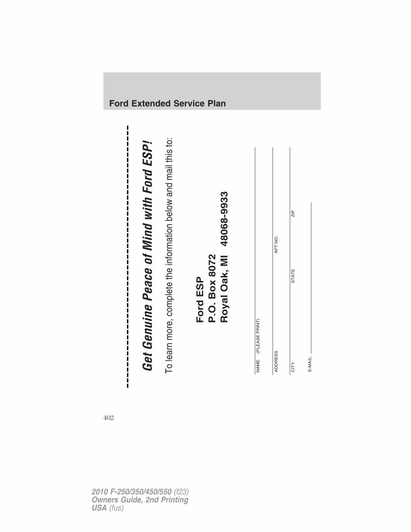
Ford Extended Service Plan
402
2010 F-250/350/450/550 (f23)Owners Guide, 2nd PrintingUSA (fus)
A
Accessory delay ........................126Air cleaner filter ...............388–390Air conditioning ........................102Airbag supplemental restraintsystem ........................................185
and child safety seats ............186description ..............................185disposal ....................................189driver airbag ............................187indicator light .........................189operation .................................187passenger airbag .....................187passenger deactivationswitch ......................................190
Ambulance packages ....................7
Antifreeze (see Enginecoolant) .....................................365
Anti-lock brake system(see Brakes) ......................269–270
Anti-theft system ..............159, 162arming the system ..........160, 162disarming a triggeredsystem .....................................163triggering .................................163
Audio system(see Radio) ......................42, 44, 51
Automatic transmission ............275driving an automaticoverdrive .................................275fluid, adding ............................384fluid, checking ........................384fluid, refill capacities ..............391
Auxiliary Input Jack ...................58
Auxiliary power point ...............123
Axlerefill capacities ........................391
B
Battery .......................................363acid, treating emergencies .....363jumping a disabled battery ....331maintenance-free ....................363replacement, specifications ...390servicing ..................................363
Bed extender ............................145Belt-Minder� .............................181
Booster seats .............................212
Brakes ........................................269anti-lock ...........................269–270anti-lock brake system (ABS)warning light ...........................270fluid, checking and adding ....383fluid, refill capacities ..............391parking ....................................270shift interlock ..........................274trailer .......................................256
Bulbs ..........................................113
C
Capacities for refilling fluids ....391
Cassette tape player ...................42
Cell phone use ............................10
Child safety seats ......................199attaching with tetherstraps .......................................207in front seat ............200, 203, 206in rear seat ......200, 203, 206–207LATCH .....................................207
Child safety seats - boosterseats ...........................................212
Cleaning your vehicleengine compartment ..............347instrument panel ............349–350interior .....................................351
Index
403
2010 F-250/350/450/550 (f23)Owners Guide, 2nd PrintingUSA (fus)
plastic parts ............................348safety belts ..............................351washing ....................................345waxing .....................................346wheels ......................................346wiper blades ............................348
Climate control (see Airconditioning or Heating) ....98, 102
Clock adjust6-CD in dash .............................53AM/FM/CD .................................46
Clutchfluid ..........................................384operation while driving ..........278recommended shift speeds ....278
Compass, electronicset zone adjustment .................36
Console ......................................122overhead ..........................121–122
Controlspower seat ...............................167steering column ......................134
Coolantchecking and adding ..............365refill capacities ................368, 391
Cruise control (see Speedcontrol) ......................................131
Customer Assistance ................303Ford accessories for yourvehicle .....................................353Ford Extended ServicePlan ..........................................400Getting assistance outside theU.S. and Canada .....................342Getting roadside assistance ...303Getting the service youneed .........................................338Ordering additional owner’sliterature .................................343
Utilizing theMediation/ArbitrationProgram ...................................341
D
Daytime running lamps (seeLamps) .......................................108Dipstick
automatic transmissionfluid ..........................................384engine oil .................................360
Driving under specialconditions ..................277, 293, 297
sand .........................................295snow and ice ...........................297through water .................296, 299
DVD system .................................67
E
Electronic message center ...24, 32
Emergencies, roadsidejump-starting ..........................331
Emergency Flashers .................304
Emission control system ..........379
Engine ........................................395cleaning ...................................347coolant .....................................365diesel ...........................................7fail-safe cooling .......................369idle speed control ...................363refill capacities ........................391service points ..................357–358starting after a collision .........305
Engine oil ..................................360checking and adding ..............360dipstick ....................................360filter, specifications ........362, 390recommendations ...................362
Index
404
2010 F-250/350/450/550 (f23)Owners Guide, 2nd PrintingUSA (fus)
refill capacities ........................391Event data recording ....................8Exhaust fumes ..........................267
F
Fail safe cooling ........................369Family entertainment system ....67Fluid capacities .........................391Fog lamps ..................................107Four-Wheel Drive vehicles .......284
description ..............................290driving off road .......................292electronic shift ................285, 290indicator light .........................286lever operated shift ................286manual locking hubs ..............284preparing to drive yourvehicle .....................................273
Fuel ............................................371calculating fueleconomy ......................26, 34, 376cap ...........................................373capacity ...................................391choosing the right fuel ...........374comparisons with EPA fueleconomy estimates .................379detergent in fuel .....................375filling your vehiclewith fuel ..................371, 373, 376filter, specifications ........371, 390fuel pump shut-off switch .....305improving fuel economy ........376octane rating ...................375, 395quality ......................................375running out of fuel .................375safety information relating toautomotive fuels .....................371
Fuel pump shut-off switch .......305
Fuses ..................................306–307
G
Gas cap (see Fuel cap) ............373
Gas mileage (see Fueleconomy) ...................................376
Gauges .........................................20transmission fluidtemperature gauge ...................24
H
Hazard flashers .........................304
Head restraints .................164, 170
Headlamps .................................107aiming ..............................109, 111autolamp system .....................107daytime running lights ...........108flash to pass ............................108high beam ...............................108replacing bulbs ...............115–117turning on and off ..................107
Heatingheater only system ...................98heating and air conditioningsystem ...............................99, 102
Homelink wireless controlsystem ........................................139
Hood ..........................................356
I
Ignition ...............................264, 395
Illuminated visor mirror ...........121
Infant seats (see Safetyseats) .........................................199
Inspection/maintenance (I/M)testing ........................................381
Index
405
2010 F-250/350/450/550 (f23)Owners Guide, 2nd PrintingUSA (fus)
Instrument panelcleaning ...........................349–350cluster ........................................14lighting up panel andinterior .....................................109
J
Jump-starting your vehicle ......331
K
Keyless entry systemautolock ...................................149keypad .....................................157locking and unlockingdoors ........................................159programming entry code .......157
Keys ...................................160–161positions of the ignition .........264
L
Lampsautolamp system .....................107daytime running light .............108fog lamps .................................107headlamps ...............................107headlamps, flash to pass ........108instrument panel, dimming ...109interior lamps .........................113replacing bulbs ...............115–119
LATCH anchors .........................207
Lights, warning and indicator ....14anti-lock brakes (ABS) ..........270
Limited-slip axle .......................273
Load limits .................................244
Loading instructions .................251
Locksautolock ...................................149
childproof ................................152doors ........................................148
Lug nuts ....................................330Lumbar support, seats .....168–169
M
Manual transmission .................278fluid capacities ........................391reverse .....................................279
Message center .....................24, 32english/metric button .........27, 36system check button ................36warning messages ...............27, 37
Mirrors ...............................126–127automatic dimming rearviewmirror ......................................126fold away .................127, 129–130side view mirrors (power) .....127signal .......................................130
Moon roof ..................................138
Motorcraft� parts ..............371, 390
N
Navigation system .......................97
O
Octane rating ............................375
Oil (see Engine oil) ..................360
P
Parking brake ............................270
Parts (see Motorcraft�parts) .........................................390
Pedals (see Power adjustablefoot pedals) ...............................131
Index
406
2010 F-250/350/450/550 (f23)Owners Guide, 2nd PrintingUSA (fus)
Power adjustable foot pedals ...131Power distribution box (seeFuses) ........................................310Power door locks ......................148Power mirrors ...........................127Power point ...............................123Power steering ..........................272
fluid, checking and adding ....382fluid, refill capacity ................391
Power Windows .........................124
Preparing to drive yourvehicle ........................................273
R
Radio ................................42, 44, 51
Rear seat entertainmentsystem ..........................................67
Rear-view camera system .........282
Relays ........................................306
Remote entry system ...............152illuminated entry ....................157locking/unlockingdoors ................................148, 153replacing the batteries ...........155
Reverse sensing system ...........280
Roadside assistance ..................303
S
Safety belts (see Safetyrestraints) ..........................173–178
Safety defects, reporting ..........344
Safety restraints ................173–178Belt-Minder� ...........................181extension assembly ................184for adults .........................174–178
for children .............................195lap belt ....................................179warning light andchime ...............................180–181
Safety restraints - LATCHanchors ......................................207Safety seats for children ..........199Safety ComplianceCertification Label ....................395Satellite Radio Information ........64Seats ..........................................164
child safety seats ....................199cleaning ...................................352heated ......................................102memory seat ...................154, 169
SecuriCode keyless entrysystem ........................................157
SecuriLock passive anti-theftsystem ................................159, 161
Servicing your vehicle ..............355
Setting the clockAM/FM/CD .................................46AM/FM/In-dash 6 CD ................53
Snowplowing .................7, 300–301
SOS Post Crash Alert ...............189
Spark plugs,specifications .....................390, 395
Special notice ................................8ambulance conversions ..............7diesel-powered vehicles .............7four-wheel drive vehicles .......302utility-type vehicles ....................7
Speed control ............................131
Starting your vehicle ........264–266jump starting ..........................331
Steering wheelcontrols ....................................134
Index
407
2010 F-250/350/450/550 (f23)Owners Guide, 2nd PrintingUSA (fus)
tilting .......................................121
SYNC� ..........................................97
T
Tailgate ......................................143
Temperature control (seeClimate control) ..........................98
Tilt steering wheel ....................121
Tire Pressure MonitoringSystem (TPMS)
Tires, Wheels and Loading ....237
Tires ...................................219–220alignment ................................229care ..........................................225changing ..........................318, 320checking the pressure ............224inflating ...................................221label .........................................236replacing ..................................227rotating ....................................229safety practices .......................228sidewall information ...............231snow tires and chains ............243spare tire .................................316terminology .............................220tire grades ...............................220treadwear ........................219, 226
Towing .......................................251recreational towing .................262Trailer BrakeController-Integrated ..............256trailer towing ..........................251wrecker ....................................336
Traction control ........................271
Trailer BrakeController-Integrated ................256
Transfer casefluid checking .........................388
Transmissionautomatic operation ...............275brake-shift interlock (BSI) ....274fluid, checking and adding(automatic) .............................384fluid, checking and adding(manual) .................................387fluid, refill capacities ..............391manual operation ....................278
Turn signal ................................112
U
Upfitter controls .......................137
USB port ......................................60
V
Vehicle Identification Number(VIN) ..........................................396
Vehicle loading ..........................244
Ventilating your vehicle ...........267
W
Warning lights (see Lights) .......14
Washer fluid ..............................359
Water, Driving through .............299
Windowspower .......................................124
Windshield washer fluid andwipers ........................................120
checking and adding fluid .....359replacing wiper blades ...........359
Wrecker towing .........................336
Index
408
2010 F-250/350/450/550 (f23)Owners Guide, 2nd PrintingUSA (fus)

![wellersofguildford.comwellersofguildford.com/content/wp-content/uploads/2017/... · Web viewALONG WTH OTHER BUMPERS [2109] 2023. *2X FORD F250 F350 F450 F550 EXCURSION HEAVY DUTY](https://img.pdfslide.net/doc/110x75/5abc7fa27f8b9ad1768e068f/viewalong-wth-other-bumpers-2109-2023-2x-ford-f250-f350-f450-f550-excursion.jpg)


![* [MARCH 1, 1996] OPP Project No. 9XXXXX - · Web viewCaterpillar Compact Wheel Loader 906H Ford Truck F350 Ford Truck F450 28.16.4. Before either of the two listed load values (GAWR](https://img.pdfslide.net/doc/110x75/5aacde8d7f8b9a2e088d822f/-march-1-1996-opp-project-no-9xxxxx-viewcaterpillar-compact-wheel-loader.jpg)