Embed Size (px)
Citation preview
State of Ohio
Department of Transportation
~Construction Inspection Forms
~7/17/2009
Ohio Department of Transportation
Division of Construction Management
1980 W. Broad Street
Columbus, Ohio 43223
Phone: (614) 466-3598
Web Address: WWW.DOT.STATE.OH.US
Construction Inspection Documentation Forms
IntroductionThe Ohio Department of Transportation is devoted to maintaining high levels of project inspection and documentation across the State. The forms and instructions contained herein are provided to project personnel to assist in the proper determination of compliance with the provisions of the contract, the measurement of quantities for payment, and the documentation of compliance and measurements.
In no instance does this document alter the provisions of the contract.
These procedures will be used to provide a uniform and fair basis of operations wherever the Ohio Department of Transportation provides supervision or engineering services for the acquisition, construction, or maintenance of materials or services. This is not a contract document, and is not to be construed in any way to obligate the Ohio Department of Transportation to perform any duties. These forms should be used in conjunction with the Construction Inspection Manual of Procedures.
Reference DocumentsDocuments normally used for detailed interpretation of substantiation requirements, practices, and test methods are:
1. Ohio Manual of Uniform Traffic Control Devices
2. Sampling and Testing Manual, Testing Administration Manual
3. Traffic Engineering Manual
4. Construction Inspection Manual of Procedures
Other documents may also be used as they are developed and published.
More testing forms (those beginning with TE) can be found online here:
http://www.dot.state.oh.us/Divisions/ConstructionMgt/Materials/Pages/TE_Forms.aspx
Districts are permitted to customize forms as long as all of the data listed on the standard forms published here is also included on the modified forms.
Many of these forms are available in Excel format with automated calculation fields. They can be found online here:
http://www.dot.state.oh.us/Divisions/ConstructionMgt/Admin/Pages/InspectionForms.aspx

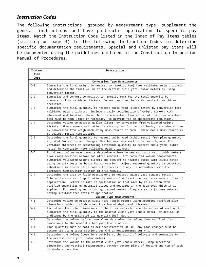
Instruction CodesThe following instructions, grouped by measurement type, supplement the general instructions and have particular application to specific pay items. Match the Instruction Code listed in the Index of Pay Items tables (starting on page 4) to the following Instruction Codes to determine specific documentation requirements. Special and unlisted pay items will be documented using the guidelines outlined in the Construction Inspection Manual of Procedures.
Instruction Code
Description
Conversion Type MeasurementsC-1 Summarize the final weight to nearest ton (metric ton) from validated weight tickets and determine the final volume to the
nearest cubic yard (cubic meter) by using conversion factor.C-2 Summarize and convert to nearest ton (metric ton) for the final quantity by conversion from validated tickets. Convert sack
and brine shipments to weight as specified.C-3 Summarize the final quantity to nearest cubic yard (cubic meter) by conversion from validated weight tickets. Include a daily
coordination of weight tickets with placement and location. Where there is a moisture limitation, at least one moisture test must be made (more if necessary) to provide for an appropriate deduction.
C-4 Determine volume to nearest gallon (liter) by conversion from validated weight tickets. Where source validation is missing, or for partial loads, determine volume by conversion from weigh-back or by measurement of tank. Where basic measurement is by volume, record temperature.
C-5 Determine the final quantity to nearest cubic yard (cubic meter) from plan quantity adjusted for errors and changes. Use for new construction on new subgrade. For variable thickness or resurfacing determine quantity to nearest cubic yard (cubic meter) by conversion from validated weight tickets.
C-6 For direct volume measurements determine volume to nearest cubic yard (cubic meter) from cross-sections before and after removal. For converted volume measurements, summarize validated weight tickets and convert to nearest cubic yard (cubic meter) using density tests as basis for conversion. Adjust measured quantity by deducting embankment in excess of allowable tolerances, if any, in accordance with the Earthwork Construction section of this manual.
C-7 Determine the area by field measurement to nearest square yard (square meter). Substantiate rates of application by means of at least one test area made at time of application. Determine rate of application on test area by calculation from verified quantities of material placed and measured in the area over which it is applied. For seeding and mulching, record number of square yards (square meters) having substantiated rates of application.
Volume Type MeasurementsV-1 Determine volume to nearest cubic yard (cubic meter) using recorded verified plan dimensions, which include a verification
of depth and thickness.V-2 Record verified plan dimensions of the forms and calculate the volume of each unit. Summarize the final quantity to the
nearest cubic yard (cubic meter) or decimal as indicated by the estimated bid quantity (Ref. No.).V-3 Determine the volume before removal or determine the volume from verified plan dimensions to the nearest cubic yard (cubic
meter).V-4 Plan quantity must be paid as per specification 203.09. Any plan changes must be documented using cross-sections per C-6 or
measurements per V-1.V-5 Determine the volume loose in a vehicle at the point of delivery and summarize to the nearest cubic yard (cubic meter).V-6 Determine the volume to the nearest cubic yard (cubic meter) using specified dimensions and vertical measurements between
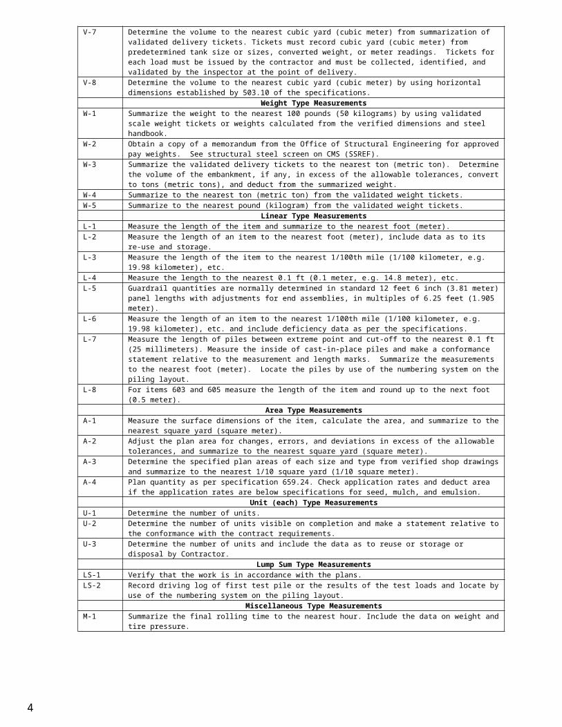
bottom plane of footing and top of rock or shale excavation.V-7 Determine the volume to the nearest cubic yard (cubic meter) from summarization of validated delivery tickets. Tickets must
record cubic yard (cubic meter) from predetermined tank size or sizes, converted weight, or meter readings. Tickets for each load must be issued by the contractor and must be collected, identified, and validated by the inspector at the point of delivery.
V-8 Determine the volume to the nearest cubic yard (cubic meter) by using horizontal dimensions established by 503.10 of the specifications.
Weight Type MeasurementsW-1 Summarize the weight to the nearest 100 pounds (50 kilograms) by using validated scale weight tickets or weights calculated
from the verified dimensions and steel handbook.W-2 Obtain a copy of a memorandum from the Office of Structural Engineering for approved pay weights. See structural steel
screen on CMS (SSREF).W-3 Summarize the validated delivery tickets to the nearest ton (metric ton). Determine the volume of the embankment, if any, in
excess of the allowable tolerances, convert to tons (metric tons), and deduct from the summarized weight.W-4 Summarize to the nearest ton (metric ton) from the validated weight tickets.W-5 Summarize to the nearest pound (kilogram) from the validated weight tickets.
Linear Type MeasurementsL-1 Measure the length of the item and summarize to the nearest foot (meter).L-2 Measure the length of an item to the nearest foot (meter), include data as to its re-use and storage.L-3 Measure the length of the item to the nearest 1/100th mile (1/100 kilometer, e.g. 19.98 kilometer), etc.L-4 Measure the length to the nearest 0.1 ft (0.1 meter, e.g. 14.8 meter), etc.L-5 Guardrail quantities are normally determined in standard 12 feet 6 inch (3.81 meter) panel lengths with adjustments for end
assemblies, in multiples of 6.25 feet (1.905 meter).L-6 Measure the length of an item to the nearest 1/100th mile (1/100 kilometer, e.g. 19.98 kilometer), etc. and include deficiency
data as per the specifications.L-7 Measure the length of piles between extreme point and cut-off to the nearest 0.1 ft (25 millimeters). Measure the inside of
cast-in-place piles and make a conformance statement relative to the measurement and length marks. Summarize the measurements to the nearest foot (meter). Locate the piles by use of the numbering system on the piling layout.
L-8 For items 603 and 605 measure the length of the item and round up to the next foot (0.5 meter).Area Type Measurements
2
A-1 Measure the surface dimensions of the item, calculate the area, and summarize to the nearest square yard (square meter).A-2 Adjust the plan area for changes, errors, and deviations in excess of the allowable tolerances, and summarize to the nearest
square yard (square meter).A-3 Determine the specified plan areas of each size and type from verified shop drawings and summarize to the nearest 1/10
square yard (1/10 square meter).A-4 Plan quantity as per specification 659.24. Check application rates and deduct area if the application rates are below
specifications for seed, mulch, and emulsion.Unit (each) Type Measurements
U-1 Determine the number of units.U-2 Determine the number of units visible on completion and make a statement relative to the conformance with the contract
requirements.U-3 Determine the number of units and include the data as to reuse or storage or disposal by Contractor.
Lump Sum Type MeasurementsLS-1 Verify that the work is in accordance with the plans.LS-2 Record driving log of first test pile or the results of the test loads and locate by use of the numbering system on the piling
layout.Miscellaneous Type Measurements
M-1 Summarize the final rolling time to the nearest hour. Include the data on weight and tire pressure.
3
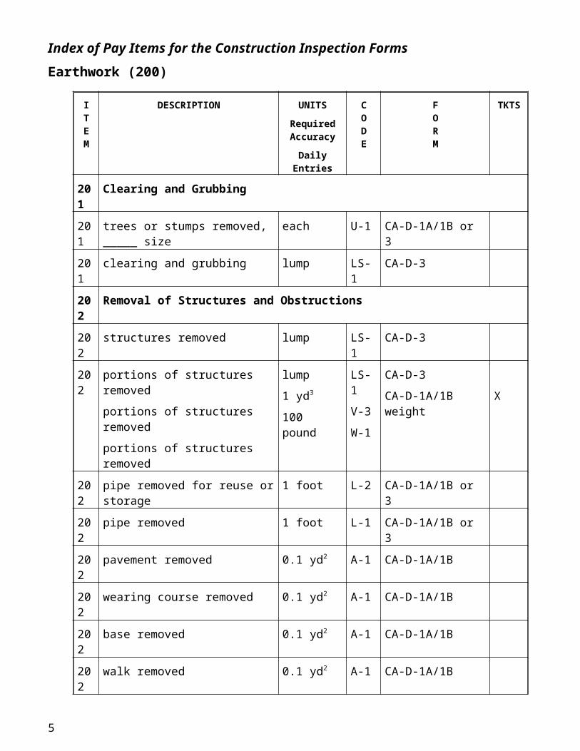
Index of Pay Items for the Construction Inspection FormsEarthwork (200)
ITEM
DESCRIPTION UNITSRequired Accuracy
Daily Entries
CODE
FORM
TKTS
201 Clearing and Grubbing
201 trees or stumps removed, _____ size each U-1 CA-D-1A/1B or 3
201 clearing and grubbing lump LS-1 CA-D-3
202 Removal of Structures and Obstructions
202 structures removed lump LS-1 CA-D-3
202 portions of structures removed
portions of structures removed
portions of structures removed
lump
1 yd3
100 pound
LS-1
V-3
W-1
CA-D-3
CA-D-1A/1B weight X
202 pipe removed for reuse or storage 1 foot L-2 CA-D-1A/1B or 3
202 pipe removed 1 foot L-1 CA-D-1A/1B or 3
202 pavement removed 0.1 yd2 A-1 CA-D-1A/1B
202 wearing course removed 0.1 yd2 A-1 CA-D-1A/1B
202 base removed 0.1 yd2 A-1 CA-D-1A/1B
202 walk removed 0.1 yd2 A-1 CA-D-1A/1B
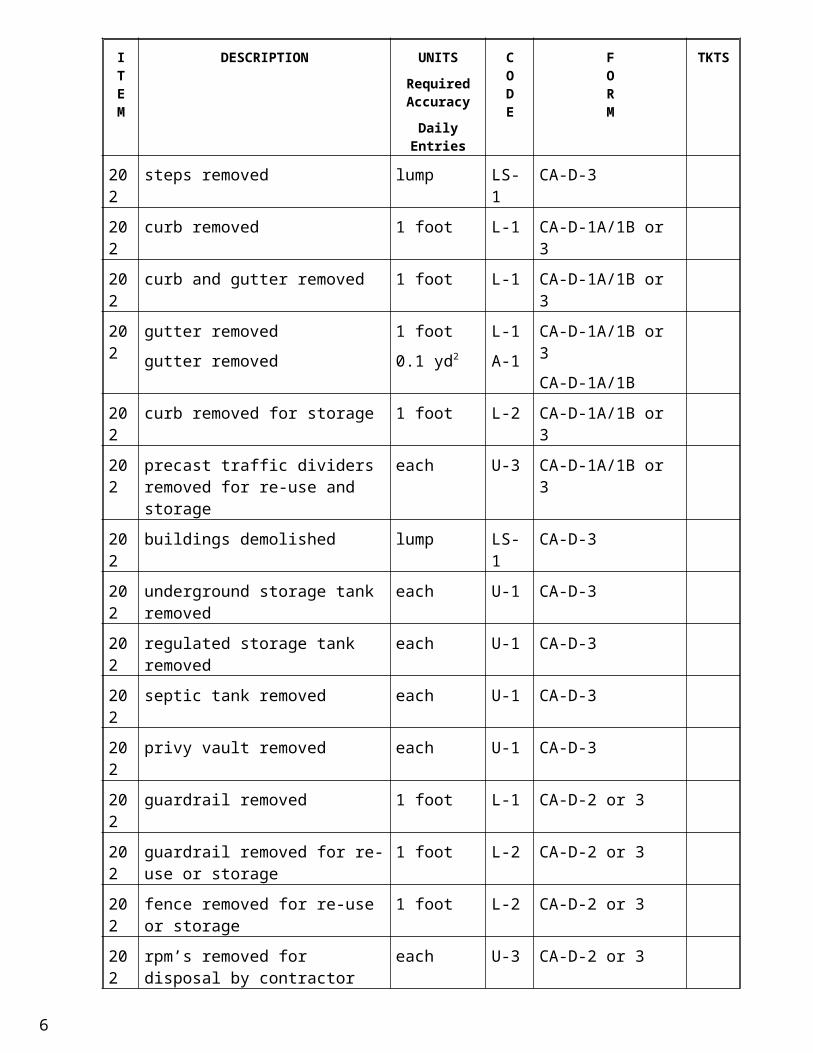
202 steps removed lump LS-1 CA-D-3
202 curb removed 1 foot L-1 CA-D-1A/1B or 3
202 curb and gutter removed 1 foot L-1 CA-D-1A/1B or 3
202 gutter removed
gutter removed
1 foot
0.1 yd2
L-1
A-1
CA-D-1A/1B or 3
CA-D-1A/1B
202 curb removed for storage 1 foot L-2 CA-D-1A/1B or 3
202 precast traffic dividers removed for re-use and storage
each U-3 CA-D-1A/1B or 3
202 buildings demolished lump LS-1 CA-D-3
202 underground storage tank removed each U-1 CA-D-3
202 regulated storage tank removed each U-1 CA-D-3
202 septic tank removed each U-1 CA-D-3
202 privy vault removed each U-1 CA-D-3
202 guardrail removed 1 foot L-1 CA-D-2 or 3
202 guardrail removed for re-use or storage
1 foot L-2 CA-D-2 or 3
4
ITEM
DESCRIPTION UNITSRequired Accuracy
Daily Entries
CODE
FORM
TKTS
202 fence removed for re-use or storage 1 foot L-2 CA-D-2 or 3
202 rpm’s removed for disposal by contractor
each U-3 CA-D-2 or 3
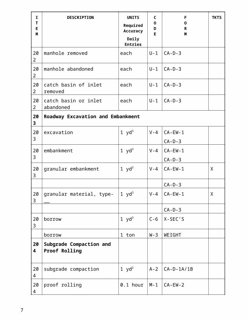
202 manhole removed each U-1 CA-D-3
202 manhole abandoned each U-1 CA-D-3
202 catch basin of inlet removed each U-1 CA-D-3
202 catch basin or inlet abandoned each U-1 CA-D-3
203 Roadway Excavation and Embankment
203 excavation 1 yd3 V-4 CA-EW-1
CA-D-3
203 embankment 1 yd3 V-4 CA-EW-1
CA-D-3
203 granular embankment 1 yd3 V-4 CA-EW-1 X
CA-D-3
203 granular material, type-__ 1 yd3 V-4 CA-EW-1 X
CA-D-3
203 borrow 1 yd3 C-6 X-SEC’S
borrow 1 ton W-3 WEIGHT
204 Subgrade Compaction and Proof Rolling
204 subgrade compaction 1 yd2 A-2 CA-D-1A/1B
204 proof rolling 0.1 hour M-1 CA-EW-2
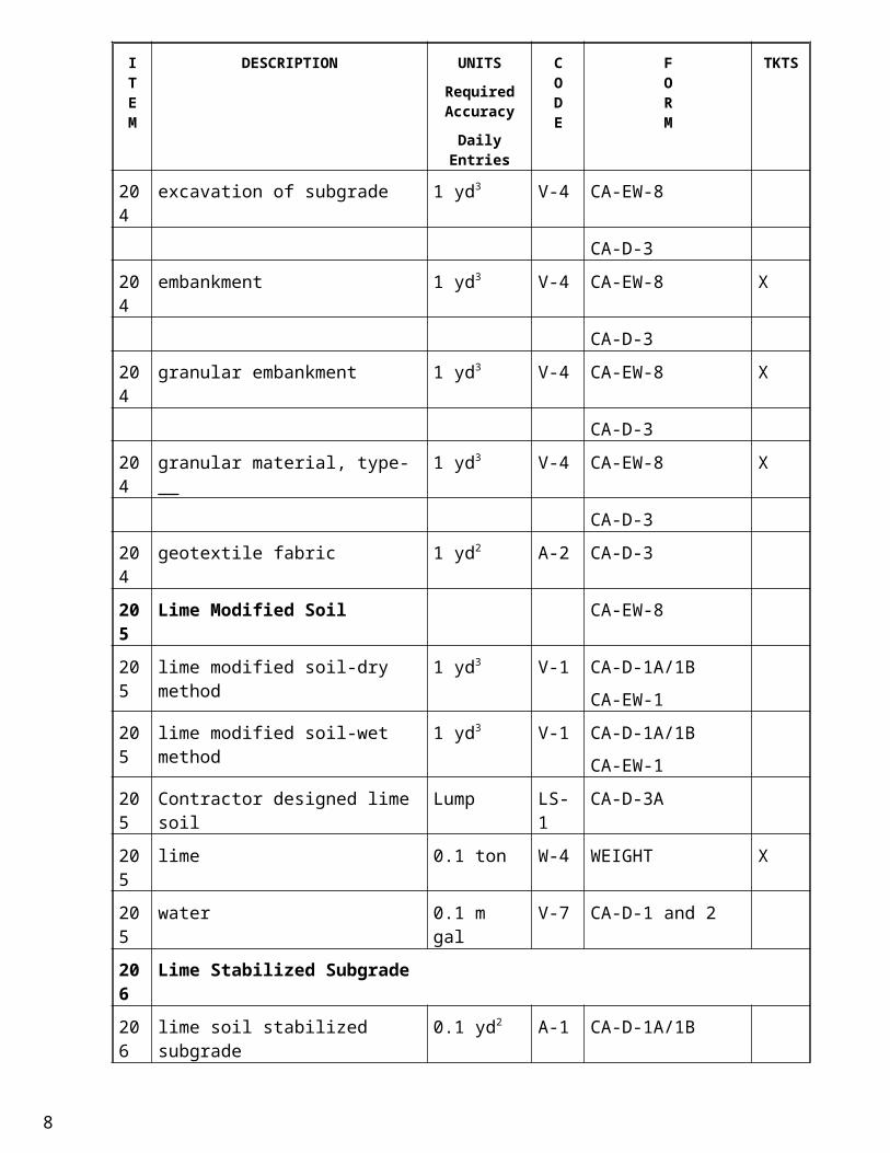
204 excavation of subgrade 1 yd3 V-4 CA-EW-8
CA-D-3
204 embankment 1 yd3 V-4 CA-EW-8 X
CA-D-3
204 granular embankment 1 yd3 V-4 CA-EW-8 X
CA-D-3
204 granular material, type-__ 1 yd3 V-4 CA-EW-8 X
CA-D-3
204 geotextile fabric 1 yd2 A-2 CA-D-3
205 Lime Modified Soil CA-EW-8
5
ITEM
DESCRIPTION UNITSRequired Accuracy
Daily Entries
CODE
FORM
TKTS
205 lime modified soil-dry method 1 yd3 V-1 CA-D-1A/1B
CA-EW-1
205 lime modified soil-wet method 1 yd3 V-1 CA-D-1A/1B
CA-EW-1
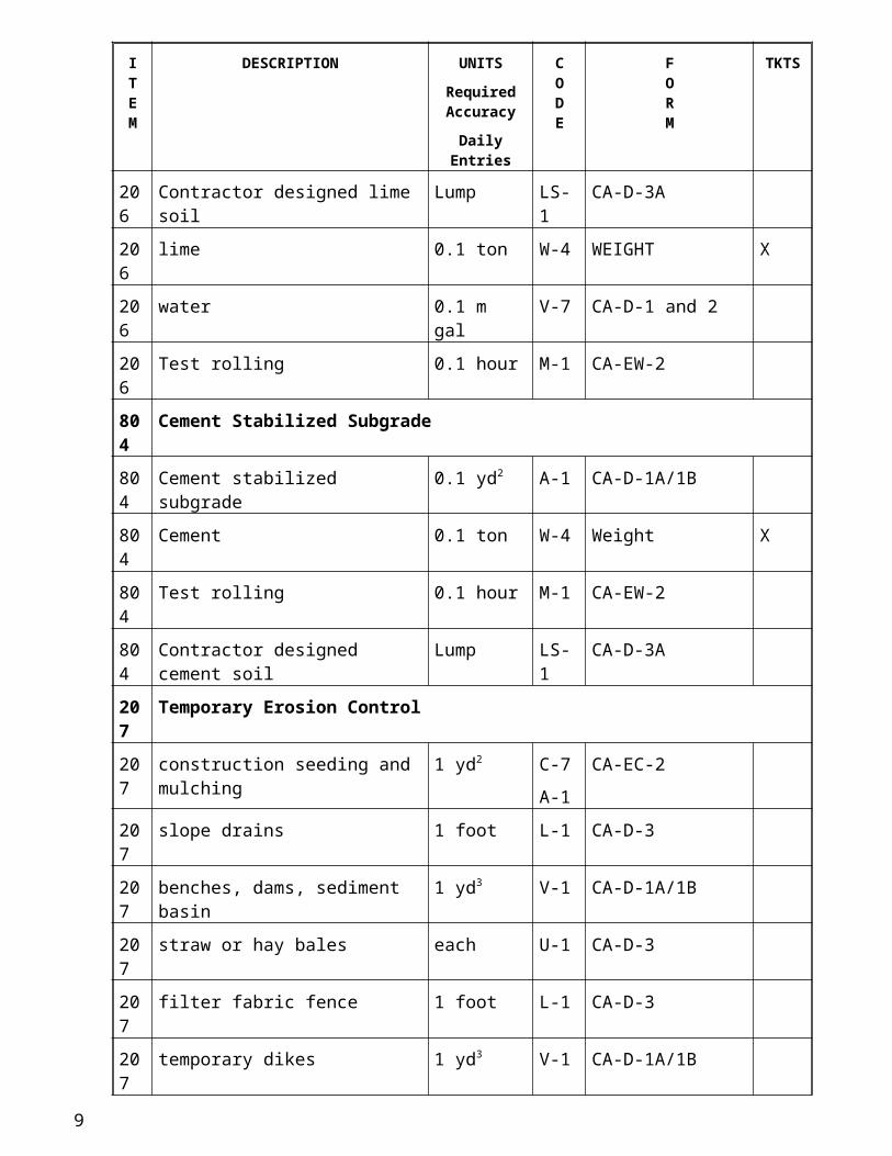
205 Contractor designed lime soil Lump LS-1 CA-D-3A
205 lime 0.1 ton W-4 WEIGHT X
205 water 0.1 m gal V-7 CA-D-1 and 2
206 Lime Stabilized Subgrade
206 lime soil stabilized subgrade 0.1 yd2 A-1 CA-D-1A/1B
206 Contractor designed lime soil Lump LS-1 CA-D-3A
206 lime 0.1 ton W-4 WEIGHT X
206 water 0.1 m gal V-7 CA-D-1 and 2
206 Test rolling 0.1 hour M-1 CA-EW-2
804 Cement Stabilized Subgrade
804 Cement stabilized subgrade 0.1 yd2 A-1 CA-D-1A/1B
804 Cement 0.1 ton W-4 Weight X
804 Test rolling 0.1 hour M-1 CA-EW-2
804 Contractor designed cement soil Lump LS-1 CA-D-3A
207 Temporary Erosion Control
207 construction seeding and mulching 1 yd2 C-7
A-1
CA-EC-2
207 slope drains 1 foot L-1 CA-D-3
207 benches, dams, sediment basin 1 yd3 V-1 CA-D-1A/1B
207 straw or hay bales each U-1 CA-D-3
207 filter fabric fence 1 foot L-1 CA-D-3
207 temporary dikes 1 yd3 V-1 CA-D-1A/1B
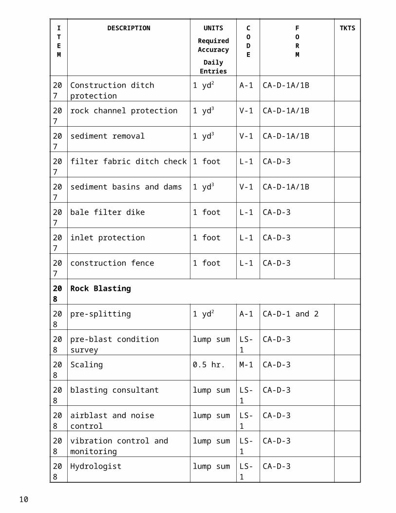
207 Construction ditch protection 1 yd2 A-1 CA-D-1A/1B
207 rock channel protection 1 yd3 V-1 CA-D-1A/1B
207 sediment removal 1 yd3 V-1 CA-D-1A/1B
207 filter fabric ditch check 1 foot L-1 CA-D-3
207 sediment basins and dams 1 yd3 V-1 CA-D-1A/1B
207 bale filter dike 1 foot L-1 CA-D-3
207 inlet protection 1 foot L-1 CA-D-36
ITEM
DESCRIPTION UNITSRequired Accuracy
Daily Entries
CODE
FORM
TKTS
207 construction fence 1 foot L-1 CA-D-3
208 Rock Blasting
208 pre-splitting 1 yd2 A-1 CA-D-1 and 2
208 pre-blast condition survey lump sum LS-1 CA-D-3
208 Scaling 0.5 hr. M-1 CA-D-3
208 blasting consultant lump sum LS-1 CA-D-3
208 airblast and noise control lump sum LS-1 CA-D-3
208 vibration control and monitoring lump sum LS-1 CA-D-3
208 Hydrologist lump sum LS-1 CA-D-3
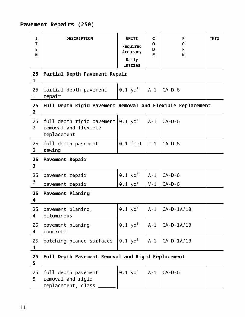
Pavement Repairs (250)
ITEM
DESCRIPTION UNITSRequired Accuracy
Daily Entries
CODE
FORM
TKTS
251 Partial Depth Pavement Repair
251 partial depth pavement repair 0.1 yd2 A-1 CA-D-6
252 Full Depth Rigid Pavement Removal and Flexible Replacement
252 full depth rigid pavement removal and flexible replacement
0.1 yd2 A-1 CA-D-6
252 full depth pavement sawing 0.1 foot L-1 CA-D-6
253 Pavement Repair
253 pavement repair
pavement repair
0.1 yd2
0.1 yd3
A-1
V-1
CA-D-6
CA-D-6
254 Pavement Planing
254 pavement planing, bituminous 0.1 yd2 A-1 CA-D-1A/1B
254 pavement planing, concrete 0.1 yd2 A-1 CA-D-1A/1B
254 patching planed surfaces 0.1 yd2 A-1 CA-D-1A/1B
255 Full Depth Pavement Removal and Rigid Replacement
255 full depth pavement removal and rigid replacement, class ______
0.1 yd2 A-1 CA-D-6
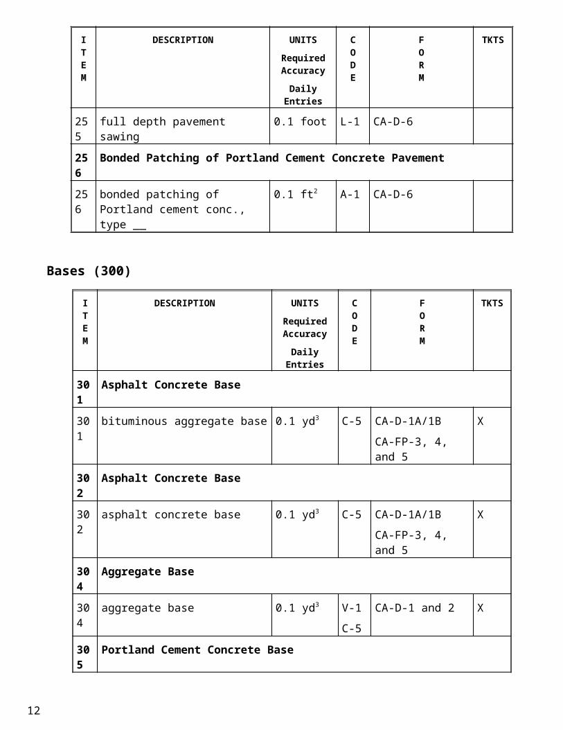
255 full depth pavement sawing 0.1 foot L-1 CA-D-6
256 Bonded Patching of Portland Cement Concrete Pavement
7
ITEM
DESCRIPTION UNITSRequired Accuracy
Daily Entries
CODE
FORM
TKTS
256 bonded patching of Portland cement conc., type __
0.1 ft2 A-1 CA-D-6
Bases (300)
ITEM
DESCRIPTION UNITSRequired Accuracy
Daily Entries
CODE
FORM
TKTS
301 Asphalt Concrete Base
301 bituminous aggregate base 0.1 yd3 C-5 CA-D-1A/1B
CA-FP-3, 4, and 5
X
302 Asphalt Concrete Base
302 asphalt concrete base 0.1 yd3 C-5 CA-D-1A/1B
CA-FP-3, 4, and 5
X
304 Aggregate Base
304 aggregate base 0.1 yd3 V-1
C-5
CA-D-1 and 2 X
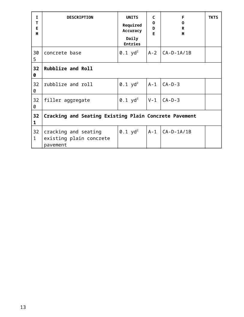
305 Portland Cement Concrete Base
305 concrete base 0.1 yd2 A-2 CA-D-1A/1B
320 Rubblize and Roll
320 rubblize and roll 0.1 yd2 A-1 CA-D-3
320 filler aggregate 0.1 yd3 V-1 CA-D-3
321 Cracking and Seating Existing Plain Concrete Pavement
321 cracking and seating existing plain concrete pavement
0.1 yd2 A-1 CA-D-1A/1B
8
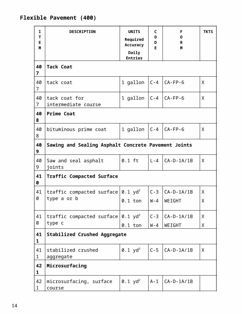
Flexible Pavement (400)
ITEM
DESCRIPTION UNITSRequired Accuracy
Daily Entries
CODE
FORM
TKTS
407 Tack Coat
407 tack coat 1 gallon C-4 CA-FP-6 X
407 tack coat for intermediate course 1 gallon C-4 CA-FP-6 X
408 Prime Coat
408 bituminous prime coat 1 gallon C-4 CA-FP-6 X
409 Sawing and Sealing Asphalt Concrete Pavement Joints
409 Saw and seal asphalt joints 0.1 ft L-4 CA-D-1A/1B X
410 Traffic Compacted Surface
410 traffic compacted surface type a or b 0.1 yd3
0.1 ton
C-3
W-4
CA-D-1A/1B
WEIGHT
X
X
410 traffic compacted surface type c 0.1 yd3
0.1 ton
C-3
W-4
CA-D-1A/1B
WEIGHT
X
X
411 Stabilized Crushed Aggregate
411 stabilized crushed aggregate 0.1 yd3 C-5 CA-D-1A/1B X
421 Microsurfacing
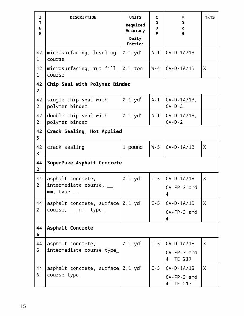
421 microsurfacing, surface course 0.1 yd2 A-1 CA-D-1A/1B
421 microsurfacing, leveling course 0.1 yd2 A-1 CA-D-1A/1B
421 microsurfacing, rut fill course 0.1 ton W-4 CA-D-1A/1B X
422 Chip Seal with Polymer Binder
422 single chip seal with polymer binder 0.1 yd2 A-1 CA-D-1A/1B, CA-D-2
422 double chip seal with polymer binder 0.1 yd2 A-1 CA-D-1A/1B, CA-D-2
423 Crack Sealing, Hot Applied
423 crack sealing 1 pound W-5 CA-D-1A/1B X
442 SuperPave Asphalt Concrete
442 asphalt concrete, intermediate course, __ mm, type __
0.1 yd3 C-5 CA-D-1A/1B
CA-FP-3 and 4
X
442 asphalt concrete, surface course, __ mm, type __
0.1 yd3 C-5 CA-D-1A/1B
CA-FP-3 and 4
X
446 Asphalt Concrete
9
ITEM
DESCRIPTION UNITSRequired Accuracy
Daily Entries
CODE
FORM
TKTS
446 asphalt concrete, intermediate course type_
0.1 yd3 C-5 CA-D-1A/1B
CA-FP-3 and 4, TE 217
X
446 asphalt concrete, surface course type_
0.1 yd3 C-5 CA-D-1A/1B
CA-FP-3 and 4, TE 217
X
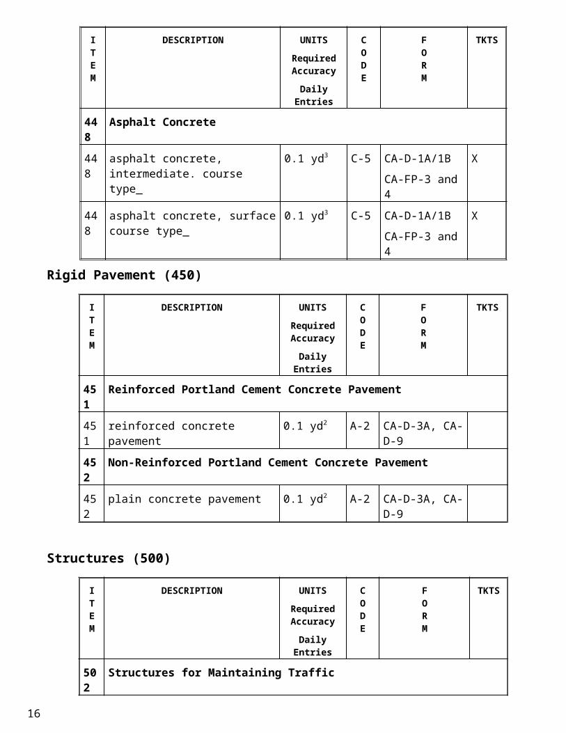
448 Asphalt Concrete
448 asphalt concrete, intermediate. course type_
0.1 yd3 C-5 CA-D-1A/1B
CA-FP-3 and 4
X
448 asphalt concrete, surface course type_
0.1 yd3 C-5 CA-D-1A/1B
CA-FP-3 and 4
X
Rigid Pavement (450)
ITEM
DESCRIPTION UNITSRequired Accuracy
Daily Entries
CODE
FORM
TKTS
451 Reinforced Portland Cement Concrete Pavement
451 reinforced concrete pavement 0.1 yd2 A-2 CA-D-3A, CA-D-9
452 Non-Reinforced Portland Cement Concrete Pavement
452 plain concrete pavement 0.1 yd2 A-2 CA-D-3A, CA-D-9
Structures (500)
ITEM
DESCRIPTION UNITSRequired Accuracy
Daily Entries
CODE
FORM
TKTS
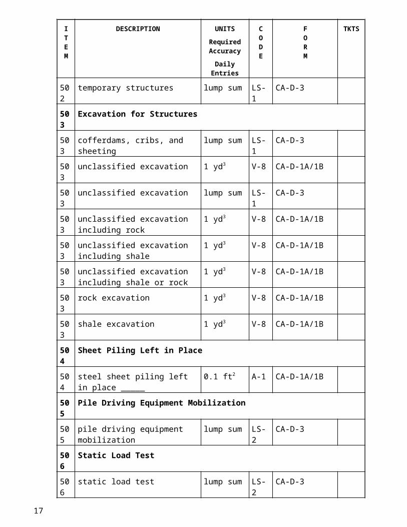
502 Structures for Maintaining Traffic
502 temporary structures lump sum LS-1 CA-D-3
503 Excavation for Structures
503 cofferdams, cribs, and sheeting lump sum LS-1 CA-D-3
503 unclassified excavation 1 yd3 V-8 CA-D-1A/1B
503 unclassified excavation lump sum LS-1 CA-D-3
10
ITEM
DESCRIPTION UNITSRequired Accuracy
Daily Entries
CODE
FORM
TKTS
503 unclassified excavation including rock
1 yd3 V-8 CA-D-1A/1B
503 unclassified excavation including shale
1 yd3 V-8 CA-D-1A/1B
503 unclassified excavation including shale or rock
1 yd3 V-8 CA-D-1A/1B
503 rock excavation 1 yd3 V-8 CA-D-1A/1B
503 shale excavation 1 yd3 V-8 CA-D-1A/1B
504 Sheet Piling Left in Place
504 steel sheet piling left in place _____ 0.1 ft2 A-1 CA-D-1A/1B
505 Pile Driving Equipment Mobilization
505 pile driving equipment mobilization lump sum LS-2 CA-D-3
506 Static Load Test
506 static load test lump sum LS-2 CA-D-3
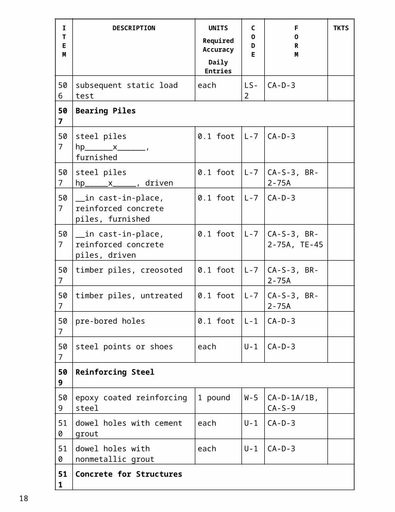
506 subsequent static load test each LS-2 CA-D-3
507 Bearing Piles
507 steel piles hp______x______, furnished
0.1 foot L-7 CA-D-3
507 steel piles hp_____x_____, driven 0.1 foot L-7 CA-S-3, BR-2-75A
507 __in cast-in-place, reinforced concrete piles, furnished
0.1 foot L-7 CA-D-3
507 __in cast-in-place, reinforced concrete piles, driven
0.1 foot L-7 CA-S-3, BR-2-75A, TE-45
507 timber piles, creosoted 0.1 foot L-7 CA-S-3, BR-2-75A
507 timber piles, untreated 0.1 foot L-7 CA-S-3, BR-2-75A
507 pre-bored holes 0.1 foot L-1 CA-D-3
507 steel points or shoes each U-1 CA-D-3
509 Reinforcing Steel
509 epoxy coated reinforcing steel 1 pound W-5 CA-D-1A/1B, CA-S-9
510 dowel holes with cement grout each U-1 CA-D-3
510 dowel holes with nonmetallic grout each U-1 CA-D-3
11
ITEM
DESCRIPTION UNITSRequired Accuracy
Daily Entries
CODE
FORM
TKTS
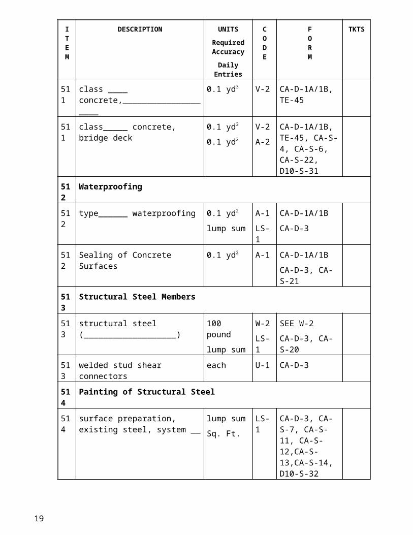
511 Concrete for Structures
511 class ____ concrete,____________________
0.1 yd3 V-2 CA-D-1A/1B, TE-45
511 class_____ concrete, bridge deck 0.1 yd3
0.1 yd2
V-2
A-2
CA-D-1A/1B, TE-45, CA-S-4, CA-S-6, CA-S-22, D10-S-31
512 Waterproofing
512 type______ waterproofing 0.1 yd2
lump sum
A-1
LS-1
CA-D-1A/1B
CA-D-3
512 Sealing of Concrete Surfaces 0.1 yd2 A-1 CA-D-1A/1B
CA-D-3, CA-S-21
513 Structural Steel Members
513 structural steel (___________________)
100 pound
lump sum
W-2
LS-1
SEE W-2
CA-D-3, CA-S-20
513 welded stud shear connectors each U-1 CA-D-3
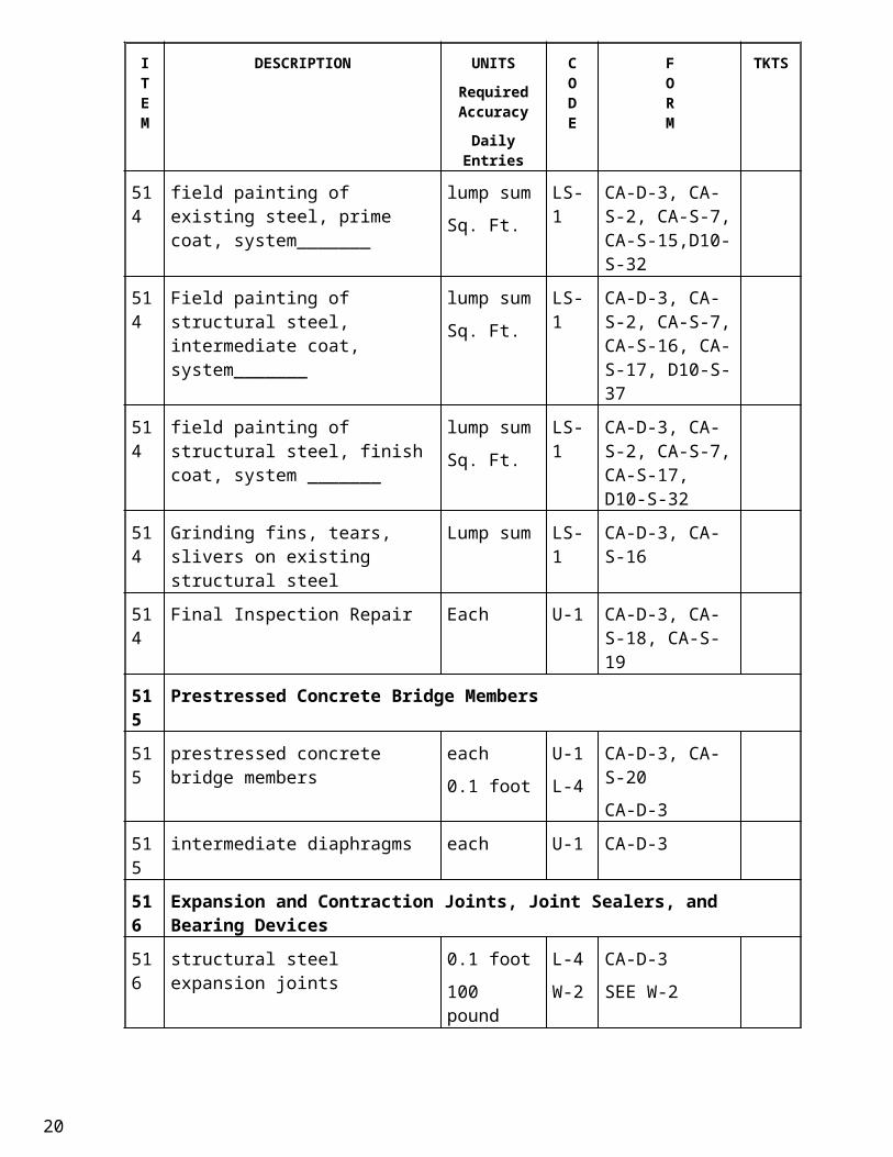
514 Painting of Structural Steel
514 surface preparation, existing steel, system __
lump sum
Sq. Ft.
LS-1 CA-D-3, CA-S-7, CA-S-11, CA-S-12,CA-S-13,CA-S-14, D10-S-32
514 field painting of existing steel, prime coat, system_______
lump sum
Sq. Ft.
LS-1 CA-D-3, CA-S-2, CA-S-7, CA-S-15,D10-S-32
514 Field painting of structural steel, intermediate coat, system_______
lump sum
Sq. Ft.
LS-1 CA-D-3, CA-S-2, CA-S-7, CA-S-16, CA-S-17, D10-S-37
514 field painting of structural steel, finish coat, system _______
lump sum
Sq. Ft.
LS-1 CA-D-3, CA-S-2, CA-S-7, CA-S-17, D10-S-32
514 Grinding fins, tears, slivers on existing structural steel
Lump sum LS-1 CA-D-3, CA-S-16
514 Final Inspection Repair Each U-1 CA-D-3, CA-S-18, CA-S-19
515 Prestressed Concrete Bridge Members
12
ITEM
DESCRIPTION UNITSRequired Accuracy
Daily Entries
CODE
FORM
TKTS
515 prestressed concrete bridge members each
0.1 foot
U-1
L-4
CA-D-3, CA-S-20
CA-D-3
515 intermediate diaphragms each U-1 CA-D-3
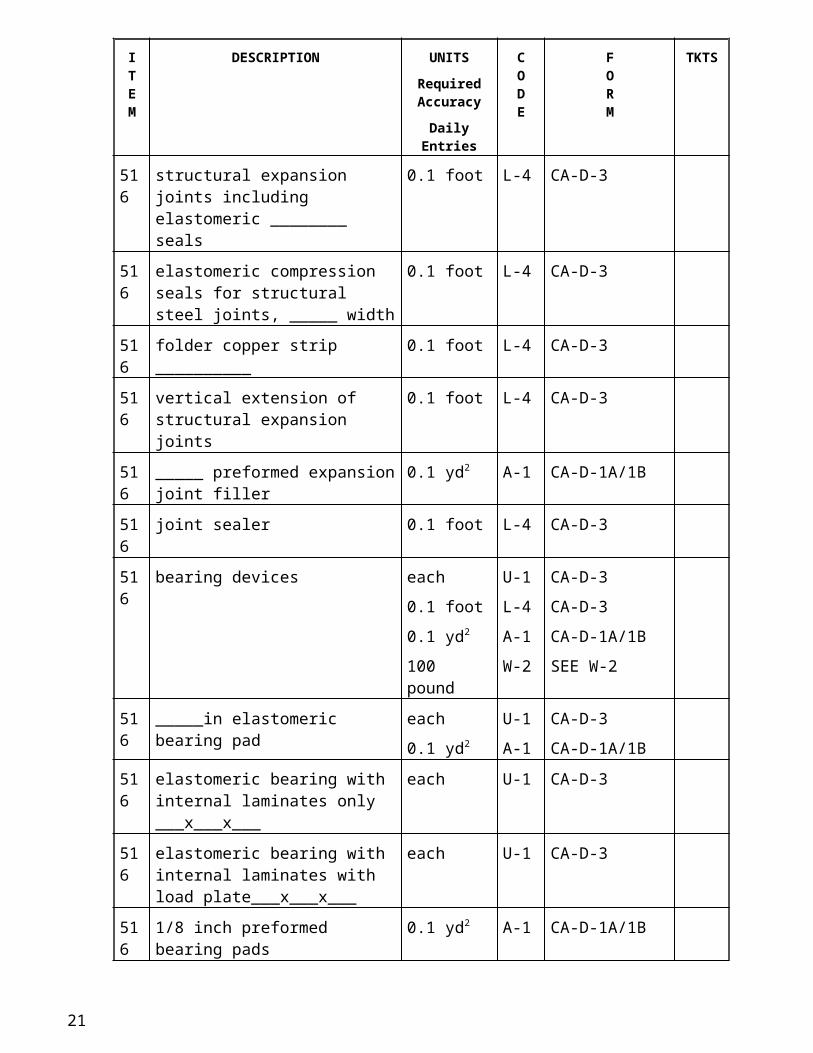
516 Expansion and Contraction Joints, Joint Sealers, and Bearing Devices
516 structural steel expansion joints 0.1 foot
100 pound
L-4
W-2
CA-D-3
SEE W-2
516 structural expansion joints including elastomeric ________ seals
0.1 foot L-4 CA-D-3
516 elastomeric compression seals for structural steel joints, _____ width
0.1 foot L-4 CA-D-3
516 folder copper strip __________ 0.1 foot L-4 CA-D-3
516 vertical extension of structural expansion joints
0.1 foot L-4 CA-D-3
516 _____ preformed expansion joint filler
0.1 yd2 A-1 CA-D-1A/1B
516 joint sealer 0.1 foot L-4 CA-D-3
516 bearing devices each
0.1 foot
0.1 yd2
100 pound
U-1
L-4
A-1
W-2
CA-D-3
CA-D-3
CA-D-1A/1B
SEE W-2
516 _____in elastomeric bearing pad each
0.1 yd2
U-1
A-1
CA-D-3
CA-D-1A/1B
516 elastomeric bearing with internal laminates only ___x___x___
each U-1 CA-D-3
516 elastomeric bearing with internal laminates with load plate___x___x___
each U-1 CA-D-3
516 1/8 inch preformed bearing pads 0.1 yd2 A-1 CA-D-1A/1B
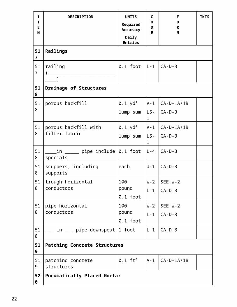
517 Railings
517 railing (____________________________)
0.1 foot L-1 CA-D-3
518 Drainage of Structures
518 porous backfill 0.1 yd3
lump sum
V-1
LS-1
CA-D-1A/1B
CA-D-3
13
ITEM
DESCRIPTION UNITSRequired Accuracy
Daily Entries
CODE
FORM
TKTS
518 porous backfill with filter fabric 0.1 yd3
lump sum
V-1
LS-1
CA-D-1A/1B
CA-D-3
518 ____in _____ pipe include specials 0.1 foot L-4 CA-D-3
518 scuppers, including supports each U-1 CA-D-3
518 trough horizontal conductors 100 pound
0.1 foot
W-2
L-1
SEE W-2
CA-D-3
518 pipe horizontal conductors 100 pound
0.1 foot
W-2
L-1
SEE W-2
CA-D-3
518 ___ in ___ pipe downspout 1 foot L-1 CA-D-3
519 Patching Concrete Structures
519 patching concrete structures 0.1 ft2 A-1 CA-D-1A/1B
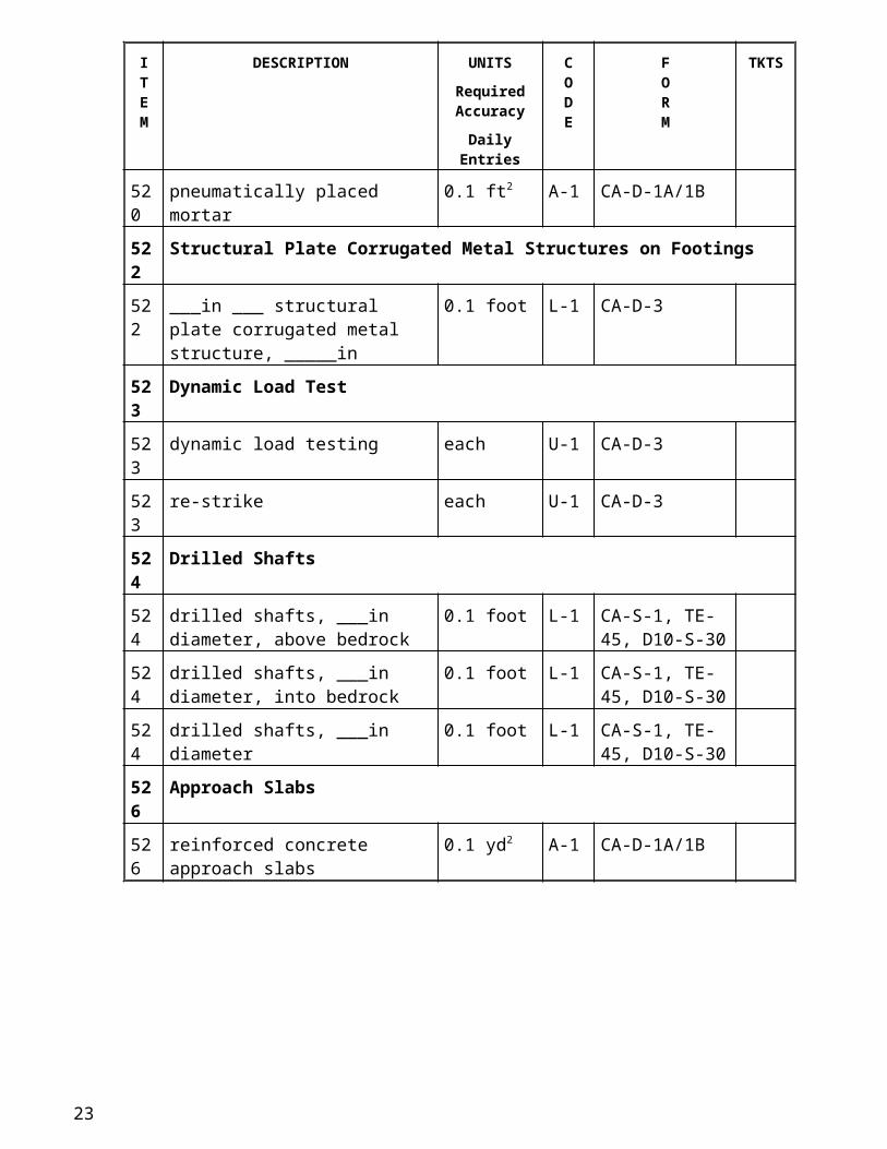
520 Pneumatically Placed Mortar
520 pneumatically placed mortar 0.1 ft2 A-1 CA-D-1A/1B
522 Structural Plate Corrugated Metal Structures on Footings
522 ___in ___ structural plate corrugated metal structure, _____in
0.1 foot L-1 CA-D-3
523 Dynamic Load Test
523 dynamic load testing each U-1 CA-D-3
523 re-strike each U-1 CA-D-3
524 Drilled Shafts
524 drilled shafts, ___in diameter, above bedrock
0.1 foot L-1 CA-S-1, TE-45, D10-S-30
524 drilled shafts, ___in diameter, into bedrock
0.1 foot L-1 CA-S-1, TE-45, D10-S-30
524 drilled shafts, ___in diameter 0.1 foot L-1 CA-S-1, TE-45, D10-S-30
526 Approach Slabs
526 reinforced concrete approach slabs 0.1 yd2 A-1 CA-D-1A/1B
14
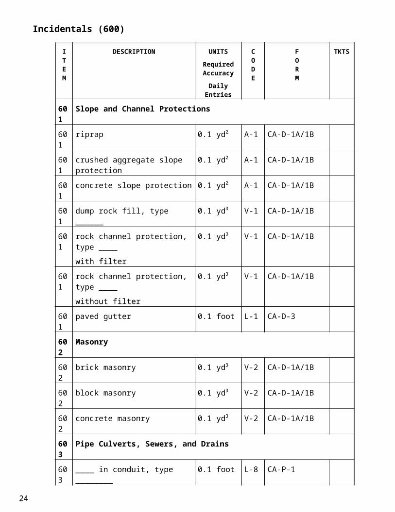
Incidentals (600)
ITEM
DESCRIPTION UNITSRequired Accuracy
Daily Entries
CODE
FORM
TKTS
601 Slope and Channel Protections
601 riprap 0.1 yd2 A-1 CA-D-1A/1B
601 crushed aggregate slope protection 0.1 yd2 A-1 CA-D-1A/1B
601 concrete slope protection 0.1 yd2 A-1 CA-D-1A/1B
601 dump rock fill, type ______ 0.1 yd3 V-1 CA-D-1A/1B
601 rock channel protection, type ____
with filter
0.1 yd3 V-1 CA-D-1A/1B
601 rock channel protection, type ____
without filter
0.1 yd3 V-1 CA-D-1A/1B
601 paved gutter 0.1 foot L-1 CA-D-3
602 Masonry
602 brick masonry 0.1 yd3 V-2 CA-D-1A/1B
602 block masonry 0.1 yd3 V-2 CA-D-1A/1B
602 concrete masonry 0.1 yd3 V-2 CA-D-1A/1B
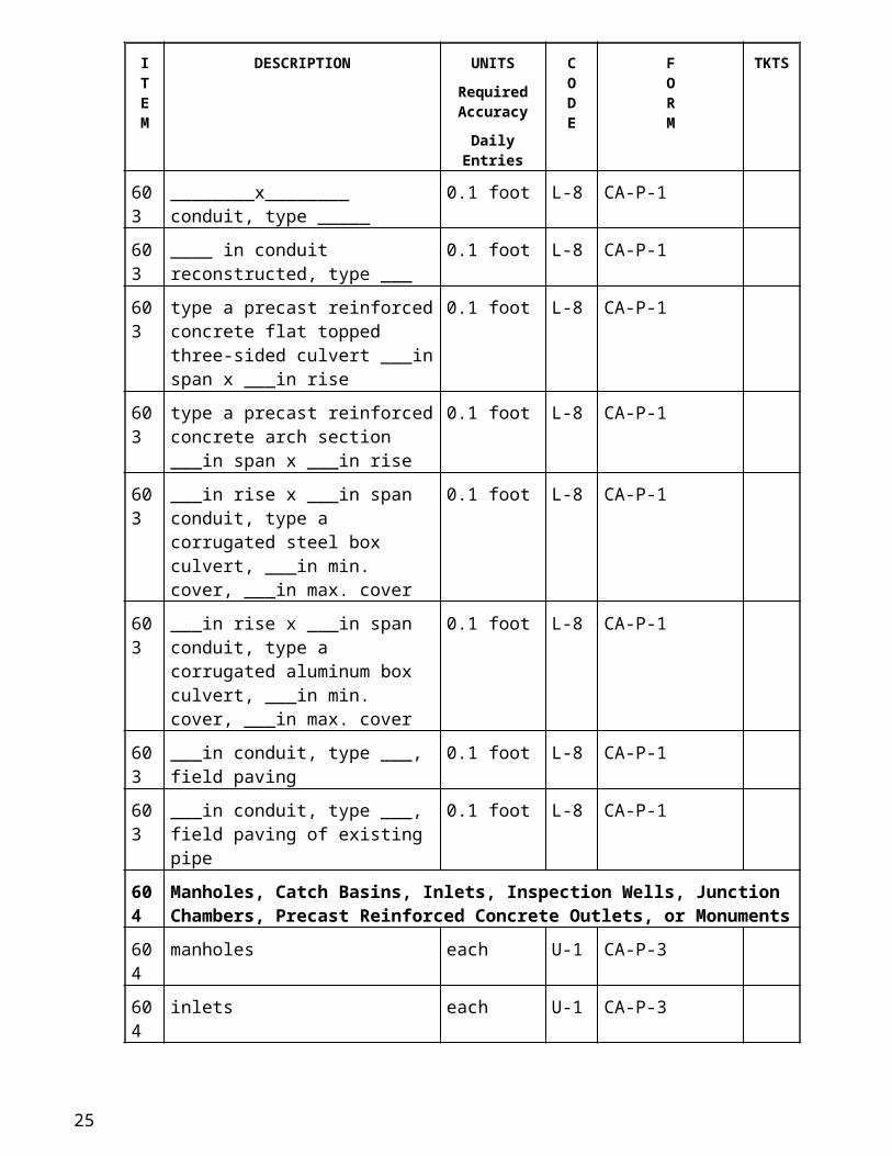
603 Pipe Culverts, Sewers, and Drains
603 ____ in conduit, type ________ 0.1 foot L-8 CA-P-1
603 ________x________ conduit, type _____
0.1 foot L-8 CA-P-1
603 ____ in conduit reconstructed, type ___
0.1 foot L-8 CA-P-1
603 type a precast reinforced concrete flat topped three-sided culvert ___in span x ___in rise
0.1 foot L-8 CA-P-1
603 type a precast reinforced concrete arch section ___in span x ___in rise
0.1 foot L-8 CA-P-1
603 ___in rise x ___in span conduit, type a corrugated steel box culvert, ___in min. cover, ___in max. cover
0.1 foot L-8 CA-P-1
603 ___in rise x ___in span conduit, type a corrugated aluminum box culvert, ___in min. cover, ___in max. cover
0.1 foot L-8 CA-P-1
603 ___in conduit, type ___, field paving 0.1 foot L-8 CA-P-1
15
ITEM
DESCRIPTION UNITSRequired Accuracy
Daily Entries
CODE
FORM
TKTS
603 ___in conduit, type ___, field paving of existing pipe
0.1 foot L-8 CA-P-1
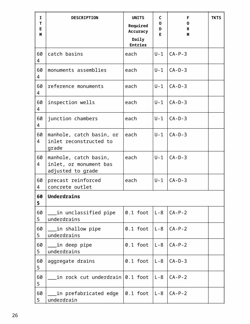
604 Manholes, Catch Basins, Inlets, Inspection Wells, Junction Chambers, Precast Reinforced Concrete Outlets, or Monuments
604 manholes each U-1 CA-P-3
604 inlets each U-1 CA-P-3
604 catch basins each U-1 CA-P-3
604 monuments assemblies each U-1 CA-D-3
604 reference monuments each U-1 CA-D-3
604 inspection wells each U-1 CA-D-3
604 junction chambers each U-1 CA-D-3
604 manhole, catch basin, or inlet reconstructed to grade
each U-1 CA-D-3
604 manhole, catch basin, inlet, or monument bas adjusted to grade
each U-1 CA-D-3
604 precast reinforced concrete outlet each U-1 CA-D-3
605 Underdrains
605 ___in unclassified pipe underdrains 0.1 foot L-8 CA-P-2
605 ___in shallow pipe underdrains 0.1 foot L-8 CA-P-2
605 ___in deep pipe underdrains 0.1 foot L-8 CA-P-2
605 aggregate drains 0.1 foot L-8 CA-D-3
605 ___in rock cut underdrain 0.1 foot L-8 CA-P-2
605 ___in prefabricated edge underdrain 0.1 foot L-8 CA-P-2
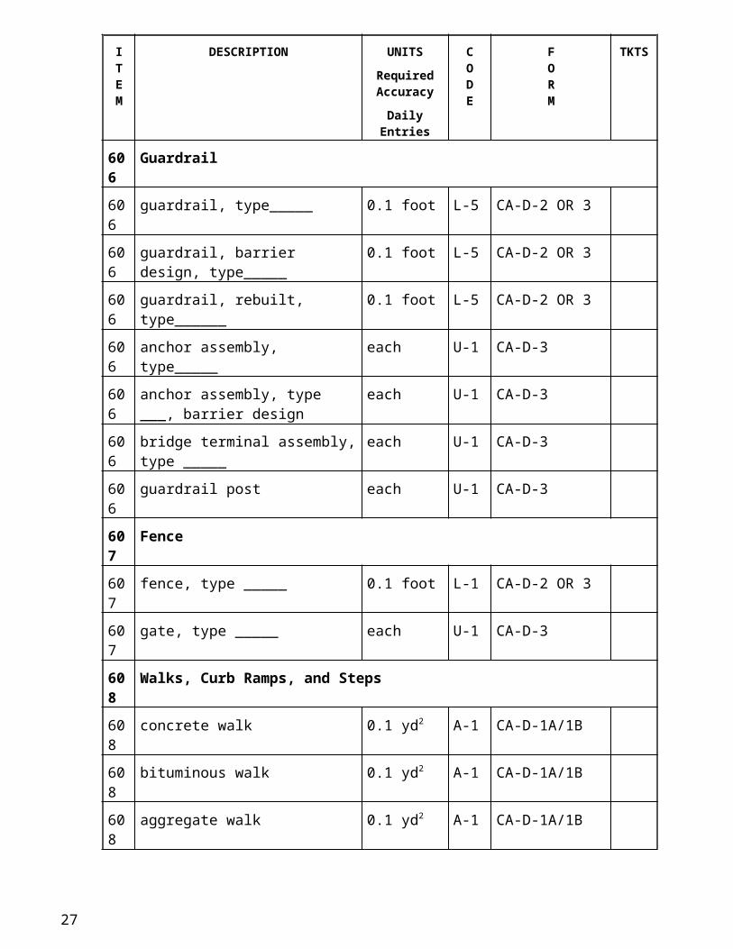
606 Guardrail
606 guardrail, type_____ 0.1 foot L-5 CA-D-2 OR 3
606 guardrail, barrier design, type_____ 0.1 foot L-5 CA-D-2 OR 3
606 guardrail, rebuilt, type______ 0.1 foot L-5 CA-D-2 OR 3
606 anchor assembly, type_____ each U-1 CA-D-3
606 anchor assembly, type ___, barrier design
each U-1 CA-D-3
606 bridge terminal assembly, type _____ each U-1 CA-D-3
606 guardrail post each U-1 CA-D-3
607 Fence
607 fence, type _____ 0.1 foot L-1 CA-D-2 OR 3
16
ITEM
DESCRIPTION UNITSRequired Accuracy
Daily Entries
CODE
FORM
TKTS
607 gate, type _____ each U-1 CA-D-3
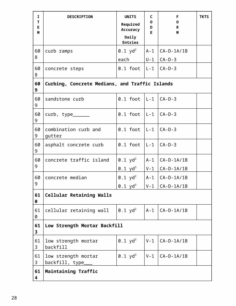
608 Walks, Curb Ramps, and Steps
608 concrete walk 0.1 yd2 A-1 CA-D-1A/1B
608 bituminous walk 0.1 yd2 A-1 CA-D-1A/1B
608 aggregate walk 0.1 yd2 A-1 CA-D-1A/1B
608 curb ramps 0.1 yd2
each
A-1
U-1
CA-D-1A/1B
CA-D-3
608 concrete steps 0.1 foot L-1 CA-D-3
609 Curbing, Concrete Medians, and Traffic Islands
609 sandstone curb 0.1 foot L-1 CA-D-3
609 curb, type______ 0.1 foot L-1 CA-D-3
609 combination curb and gutter 0.1 foot L-1 CA-D-3
609 asphalt concrete curb 0.1 foot L-1 CA-D-3
609 concrete traffic island 0.1 yd2
0.1 yd3
A-1
V-1
CA-D-1A/1B
CA-D-1A/1B
609 concrete median 0.1 yd2
0.1 yd3
A-1
V-1
CA-D-1A/1B
CA-D-1A/1B
610 Cellular Retaining Walls
610 cellular retaining wall 0.1 yd2 A-1 CA-D-1A/1B
613 Low Strength Mortar Backfill
613 low strength mortar backfill 0.1 yd3 V-1 CA-D-1A/1B
613 low strength mortar backfill, type___ 0.1 yd3 V-1 CA-D-1A/1B
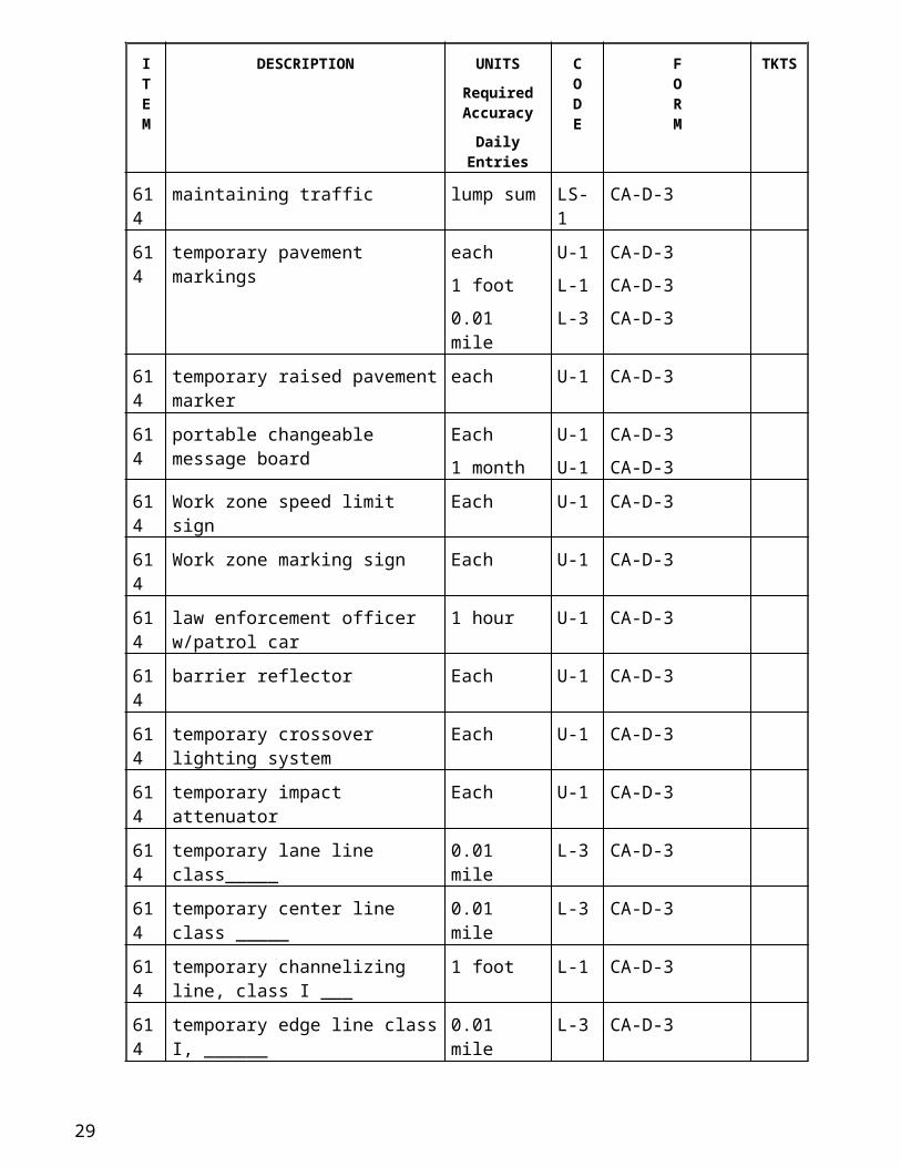
614 Maintaining Traffic
614 maintaining traffic lump sum LS-1 CA-D-3
614 temporary pavement markings each
1 foot
0.01 mile
U-1
L-1
L-3
CA-D-3
CA-D-3
CA-D-3
614 temporary raised pavement marker each U-1 CA-D-3
614 portable changeable message board Each
1 month
U-1
U-1
CA-D-3
CA-D-3
614 Work zone speed limit sign Each U-1 CA-D-3
614 Work zone marking sign Each U-1 CA-D-3
17
ITEM
DESCRIPTION UNITSRequired Accuracy
Daily Entries
CODE
FORM
TKTS
614 law enforcement officer w/patrol car 1 hour U-1 CA-D-3
614 barrier reflector Each U-1 CA-D-3
614 temporary crossover lighting system Each U-1 CA-D-3
614 temporary impact attenuator Each U-1 CA-D-3
614 temporary lane line class_____ 0.01 mile L-3 CA-D-3
614 temporary center line class _____ 0.01 mile L-3 CA-D-3
614 temporary channelizing line, class I ___
1 foot L-1 CA-D-3
614 temporary edge line class I, ______ 0.01 mile L-3 CA-D-3
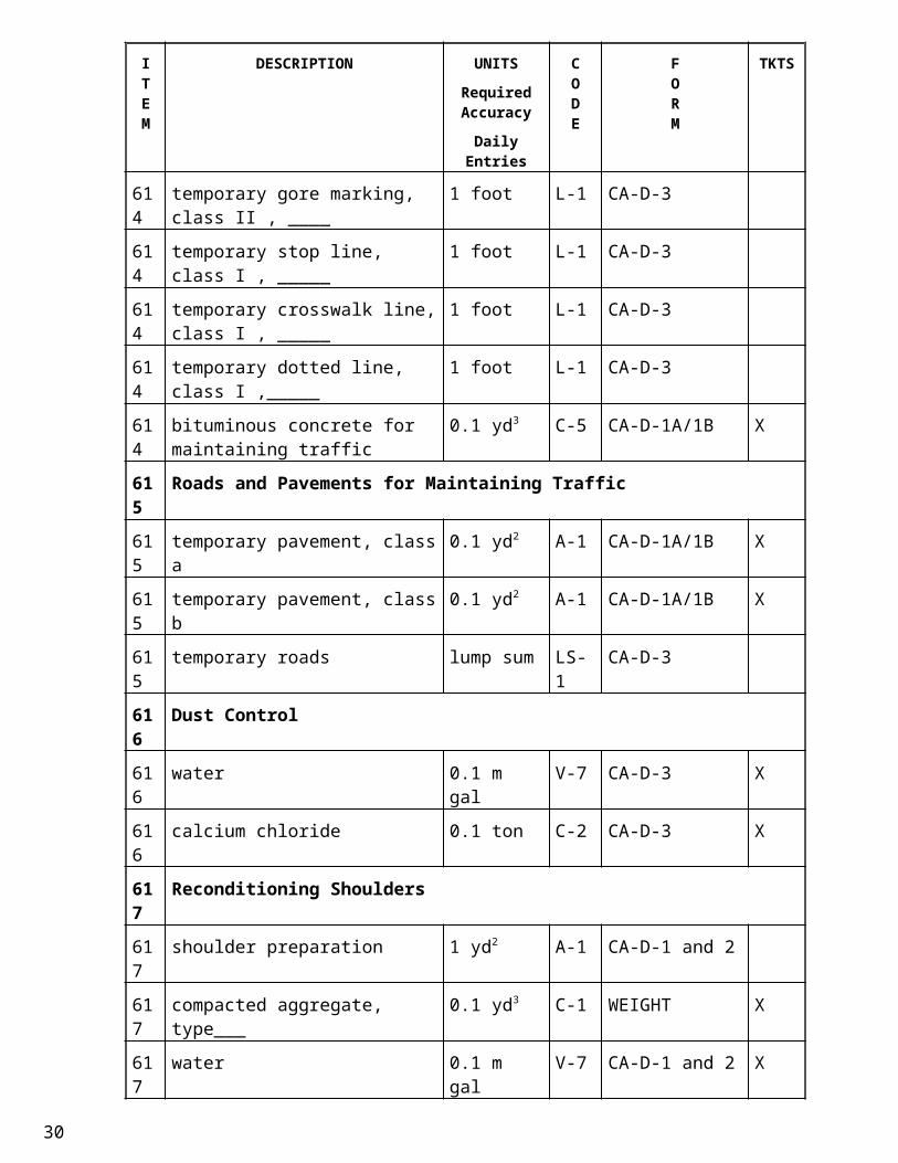
614 temporary gore marking, class II , ____
1 foot L-1 CA-D-3
614 temporary stop line, class I , _____ 1 foot L-1 CA-D-3
614 temporary crosswalk line, class I , _____
1 foot L-1 CA-D-3
614 temporary dotted line, class I ,_____ 1 foot L-1 CA-D-3
614 bituminous concrete for maintaining traffic
0.1 yd3 C-5 CA-D-1A/1B X
615 Roads and Pavements for Maintaining Traffic
615 temporary pavement, class a 0.1 yd2 A-1 CA-D-1A/1B X
615 temporary pavement, class b 0.1 yd2 A-1 CA-D-1A/1B X
615 temporary roads lump sum LS-1 CA-D-3
616 Dust Control
616 water 0.1 m gal V-7 CA-D-3 X
616 calcium chloride 0.1 ton C-2 CA-D-3 X
617 Reconditioning Shoulders
617 shoulder preparation 1 yd2 A-1 CA-D-1 and 2
617 compacted aggregate, type___ 0.1 yd3 C-1 WEIGHT X
617 water 0.1 m gal V-7 CA-D-1 and 2 X
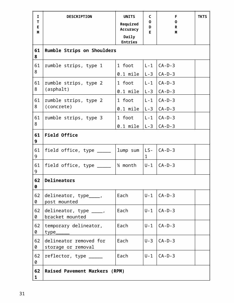
618 Rumble Strips on Shoulders
618 rumble strips, type 1 1 foot
0.1 mile
L-1
L-3
CA-D-3
CA-D-3
618 rumble strips, type 2 (asphalt) 1 foot
0.1 mile
L-1
L-3
CA-D-3
CA-D-3
18
ITEM
DESCRIPTION UNITSRequired Accuracy
Daily Entries
CODE
FORM
TKTS
618 rumble strips, type 2 (concrete) 1 foot
0.1 mile
L-1
L-3
CA-D-3
CA-D-3
618 rumble strips, type 3 1 foot
0.1 mile
L-1
L-3
CA-D-3
CA-D-3
619 Field Office
619 field office, type _____ lump sum LS-1 CA-D-3
619 field office, type _____ ½ month U-1 CA-D-3
620 Delineators
620 delineator, type____, post mounted Each U-1 CA-D-3
620 delineator, type ____, bracket mounted
Each U-1 CA-D-3
620 temporary delineator, type_____ Each U-1 CA-D-3
620 delineator removed for storage or removal
Each U-3 CA-D-3
620 reflector, type _____ Each U-1 CA-D-3
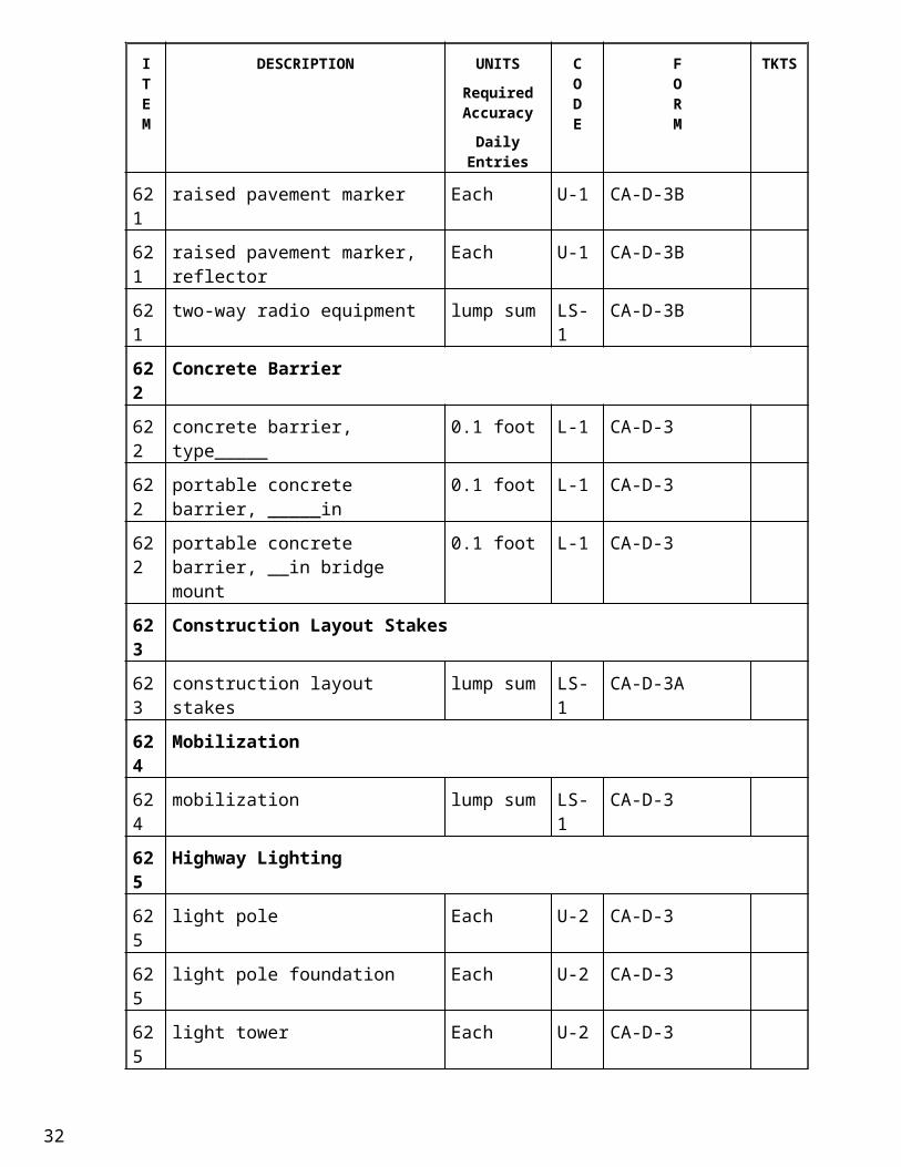
621 Raised Pavement Markers (RPM)
621 raised pavement marker Each U-1 CA-D-3B
621 raised pavement marker, reflector Each U-1 CA-D-3B
621 two-way radio equipment lump sum LS-1 CA-D-3B
622 Concrete Barrier
622 concrete barrier, type_____ 0.1 foot L-1 CA-D-3
622 portable concrete barrier, _____in 0.1 foot L-1 CA-D-3
622 portable concrete barrier, __in bridge mount
0.1 foot L-1 CA-D-3
623 Construction Layout Stakes
623 construction layout stakes lump sum LS-1 CA-D-3A
624 Mobilization
624 mobilization lump sum LS-1 CA-D-3
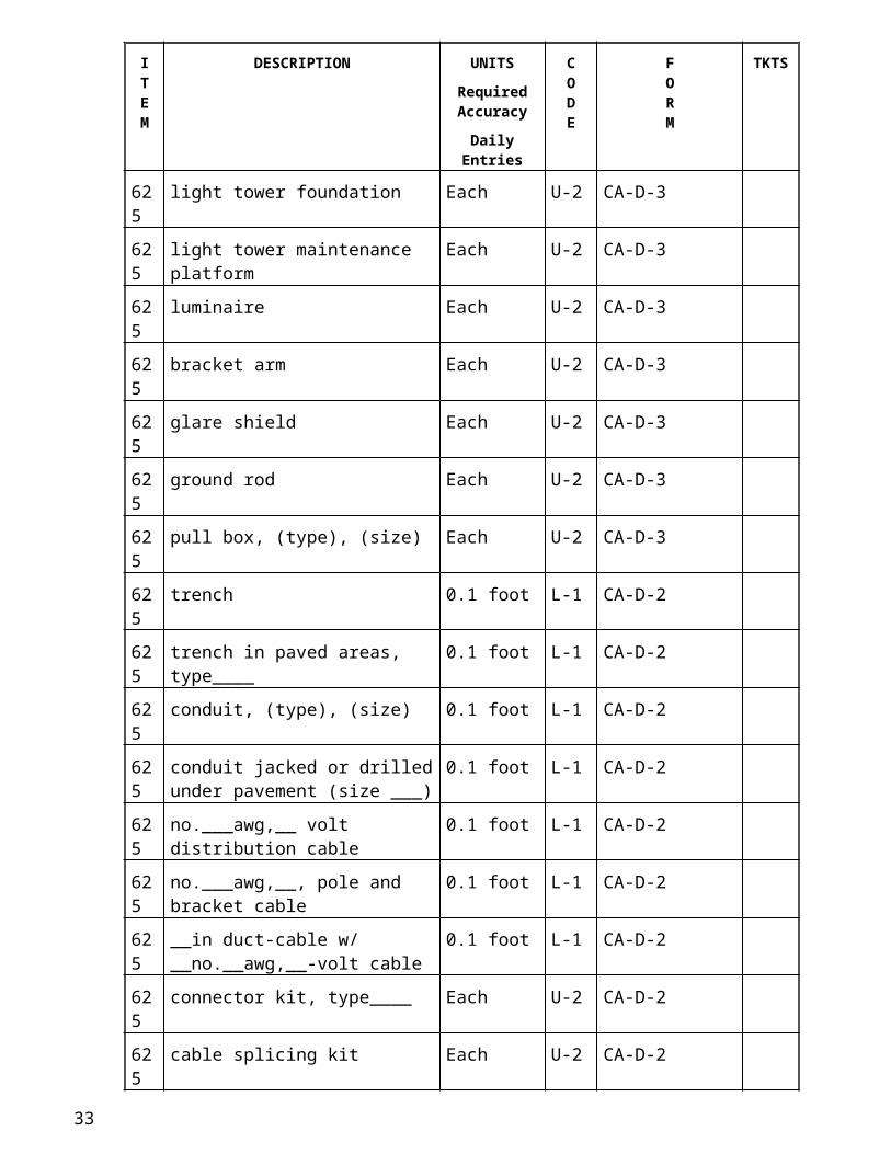
625 Highway Lighting
625 light pole Each U-2 CA-D-3
625 light pole foundation Each U-2 CA-D-3
625 light tower Each U-2 CA-D-3
625 light tower foundation Each U-2 CA-D-3
19
ITEM
DESCRIPTION UNITSRequired Accuracy
Daily Entries
CODE
FORM
TKTS
625 light tower maintenance platform Each U-2 CA-D-3
625 luminaire Each U-2 CA-D-3
625 bracket arm Each U-2 CA-D-3
625 glare shield Each U-2 CA-D-3
625 ground rod Each U-2 CA-D-3
625 pull box, (type), (size) Each U-2 CA-D-3
625 trench 0.1 foot L-1 CA-D-2
625 trench in paved areas, type____ 0.1 foot L-1 CA-D-2
625 conduit, (type), (size) 0.1 foot L-1 CA-D-2
625 conduit jacked or drilled under pavement (size ___)
0.1 foot L-1 CA-D-2
625 no.___awg,__ volt distribution cable 0.1 foot L-1 CA-D-2
625 no.___awg,__, pole and bracket cable
0.1 foot L-1 CA-D-2
625 __in duct-cable w/ __no.__awg,__-volt cable
0.1 foot L-1 CA-D-2
625 connector kit, type____ Each U-2 CA-D-2
625 cable splicing kit Each U-2 CA-D-2
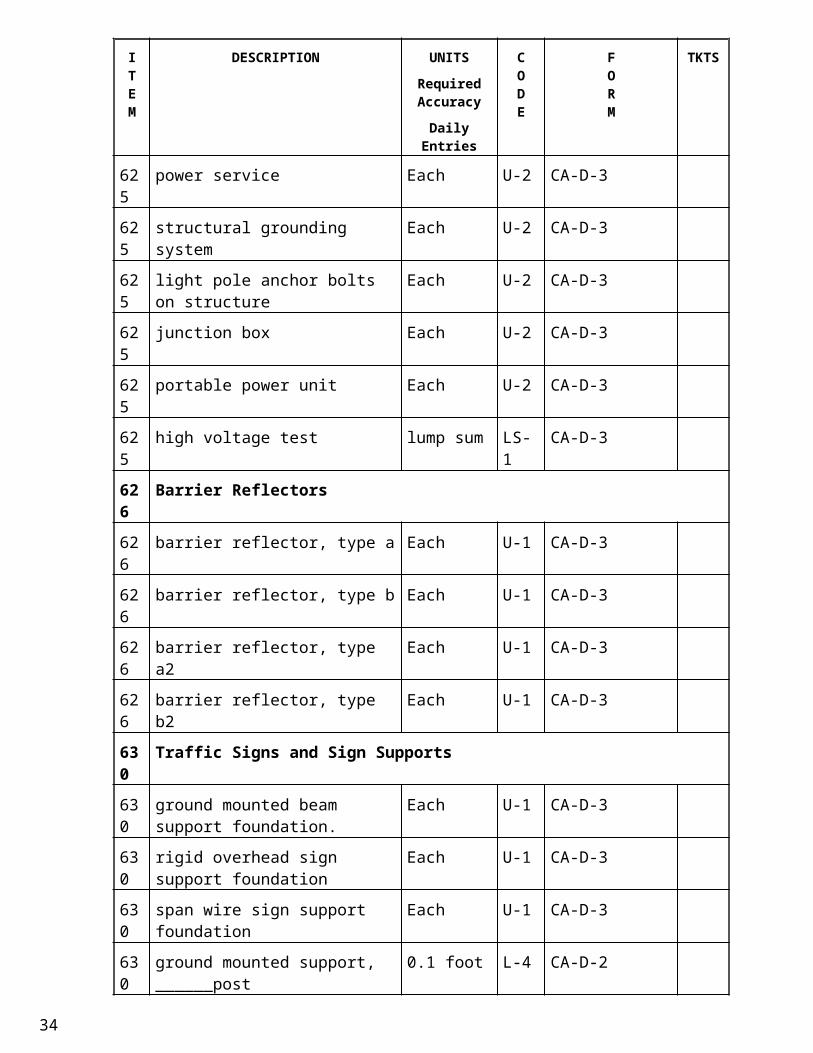
625 power service Each U-2 CA-D-3
625 structural grounding system Each U-2 CA-D-3
625 light pole anchor bolts on structure Each U-2 CA-D-3
625 junction box Each U-2 CA-D-3
625 portable power unit Each U-2 CA-D-3
625 high voltage test lump sum LS-1 CA-D-3
626 Barrier Reflectors
626 barrier reflector, type a Each U-1 CA-D-3
626 barrier reflector, type b Each U-1 CA-D-3
626 barrier reflector, type a2 Each U-1 CA-D-3
626 barrier reflector, type b2 Each U-1 CA-D-3
630 Traffic Signs and Sign Supports
630 ground mounted beam support foundation.
Each U-1 CA-D-3
630 rigid overhead sign support foundation
Each U-1 CA-D-3
20
ITEM
DESCRIPTION UNITSRequired Accuracy
Daily Entries
CODE
FORM
TKTS
630 span wire sign support foundation Each U-1 CA-D-3
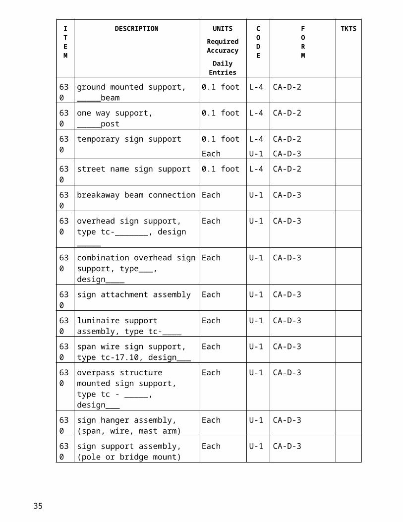
630 ground mounted support, ______post 0.1 foot L-4 CA-D-2
630 ground mounted support, _____beam 0.1 foot L-4 CA-D-2
630 one way support, _____post 0.1 foot L-4 CA-D-2
630 temporary sign support 0.1 foot
Each
L-4
U-1
CA-D-2
CA-D-3
630 street name sign support 0.1 foot L-4 CA-D-2
630 breakaway beam connection Each U-1 CA-D-3
630 overhead sign support, type tc-_______, design _____
Each U-1 CA-D-3
630 combination overhead sign support, type___, design____
Each U-1 CA-D-3
630 sign attachment assembly Each U-1 CA-D-3
630 luminaire support assembly, type tc-____
Each U-1 CA-D-3
630 span wire sign support, type tc-17.10, design___
Each U-1 CA-D-3
630 overpass structure mounted sign support, type tc - _____, design___
Each U-1 CA-D-3
630 sign hanger assembly, (span, wire, mast arm)
Each U-1 CA-D-3
630 sign support assembly, (pole or bridge mount)
Each U-1 CA-D-3
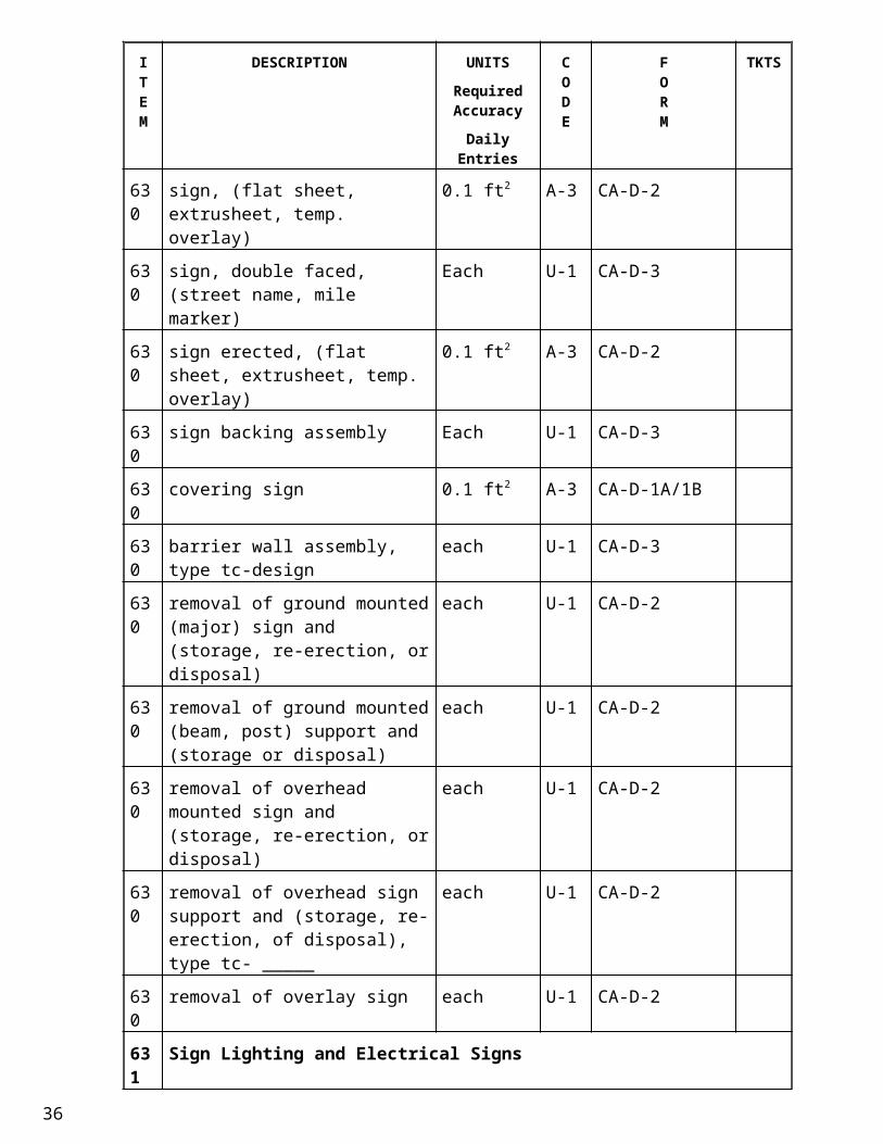
630 sign, (flat sheet, extrusheet, temp. overlay)
0.1 ft2 A-3 CA-D-2
630 sign, double faced, (street name, mile marker)
Each U-1 CA-D-3
630 sign erected, (flat sheet, extrusheet, temp. overlay)
0.1 ft2 A-3 CA-D-2
630 sign backing assembly Each U-1 CA-D-3
630 covering sign 0.1 ft2 A-3 CA-D-1A/1B
630 barrier wall assembly, type tc-design each U-1 CA-D-3
630 removal of ground mounted (major) sign and (storage, re-erection, or disposal)
each U-1 CA-D-2
21
ITEM
DESCRIPTION UNITSRequired Accuracy
Daily Entries
CODE
FORM
TKTS
630 removal of ground mounted (beam, post) support and (storage or disposal)
each U-1 CA-D-2
630 removal of overhead mounted sign and (storage, re-erection, or disposal)
each U-1 CA-D-2
630 removal of overhead sign support and (storage, re-erection, of disposal), type tc- _____
each U-1 CA-D-2
630 removal of overlay sign each U-1 CA-D-2
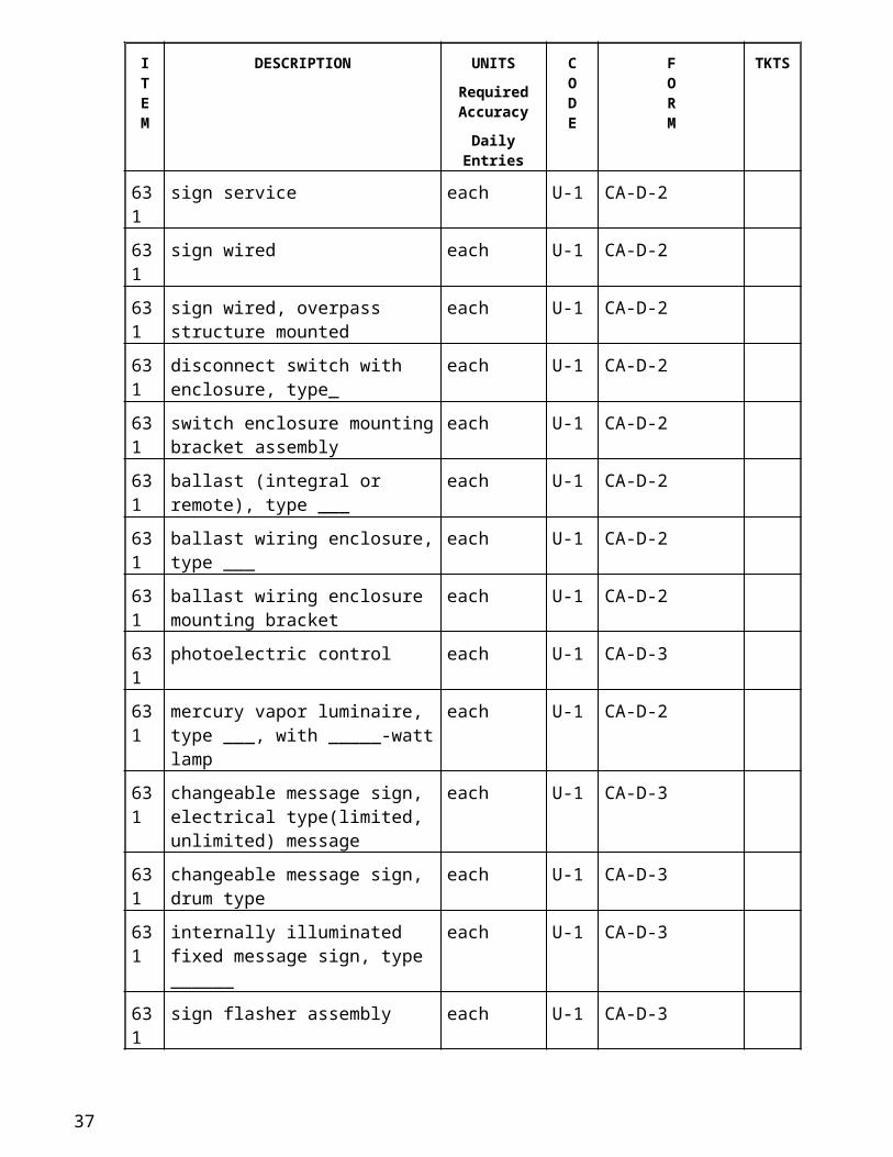
631 Sign Lighting and Electrical Signs
631 sign service each U-1 CA-D-2
631 sign wired each U-1 CA-D-2
631 sign wired, overpass structure mounted
each U-1 CA-D-2
631 disconnect switch with enclosure, type_
each U-1 CA-D-2
631 switch enclosure mounting bracket assembly
each U-1 CA-D-2
631 ballast (integral or remote), type ___ each U-1 CA-D-2
631 ballast wiring enclosure, type ___ each U-1 CA-D-2
631 ballast wiring enclosure mounting bracket
each U-1 CA-D-2
631 photoelectric control each U-1 CA-D-3
631 mercury vapor luminaire, type ___, with _____-watt lamp
each U-1 CA-D-2
631 changeable message sign, electrical type(limited, unlimited) message
each U-1 CA-D-3
631 changeable message sign, drum type each U-1 CA-D-3
631 internally illuminated fixed message sign, type ______
each U-1 CA-D-3
631 sign flasher assembly each U-1 CA-D-3
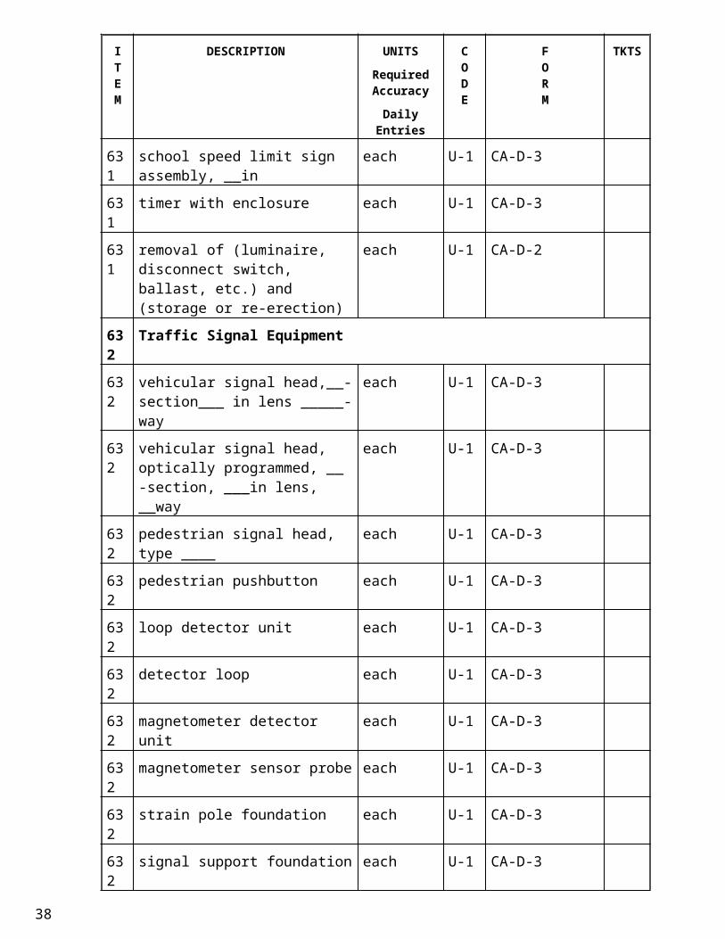
631 school speed limit sign assembly, __in
each U-1 CA-D-3
631 timer with enclosure each U-1 CA-D-3
631 removal of (luminaire, disconnect switch, ballast, etc.) and (storage or re-erection)
each U-1 CA-D-2
22
ITEM
DESCRIPTION UNITSRequired Accuracy
Daily Entries
CODE
FORM
TKTS
632 Traffic Signal Equipment
632 vehicular signal head,__-section___ in lens _____-way
each U-1 CA-D-3
632 vehicular signal head, optically programmed, __ -section, ___in lens, __way
each U-1 CA-D-3
632 pedestrian signal head, type ____ each U-1 CA-D-3
632 pedestrian pushbutton each U-1 CA-D-3
632 loop detector unit each U-1 CA-D-3
632 detector loop each U-1 CA-D-3
632 magnetometer detector unit each U-1 CA-D-3
632 magnetometer sensor probe each U-1 CA-D-3
632 strain pole foundation each U-1 CA-D-3
632 signal support foundation each U-1 CA-D-3
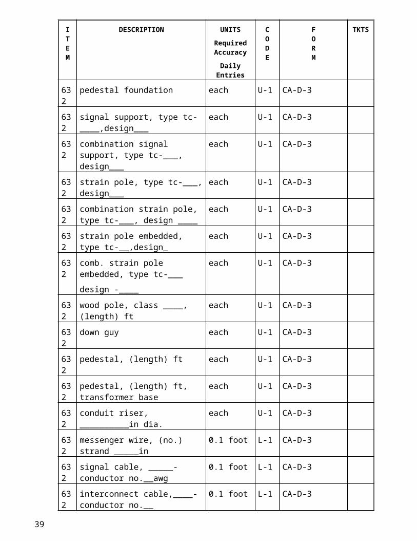
632 pedestal foundation each U-1 CA-D-3
632 signal support, type tc-____,design___
each U-1 CA-D-3
632 combination signal support, type tc-___, design___
each U-1 CA-D-3
632 strain pole, type tc-___, design___ each U-1 CA-D-3
632 combination strain pole, type tc-___, design ____
each U-1 CA-D-3
632 strain pole embedded, type tc-__,design_
each U-1 CA-D-3
632 comb. strain pole embedded, type tc-___
design -____
each U-1 CA-D-3
632 wood pole, class ____, (length) ft each U-1 CA-D-3
632 down guy each U-1 CA-D-3
632 pedestal, (length) ft each U-1 CA-D-3
632 pedestal, (length) ft, transformer base each U-1 CA-D-3
632 conduit riser, __________in dia. each U-1 CA-D-3
632 messenger wire, (no.) strand _____in 0.1 foot L-1 CA-D-3
632 signal cable, _____-conductor no.__awg
0.1 foot L-1 CA-D-3
23
ITEM
DESCRIPTION UNITSRequired Accuracy
Daily Entries
CODE
FORM
TKTS
632 interconnect cable,____-conductor no.__
0.1 foot L-1 CA-D-3
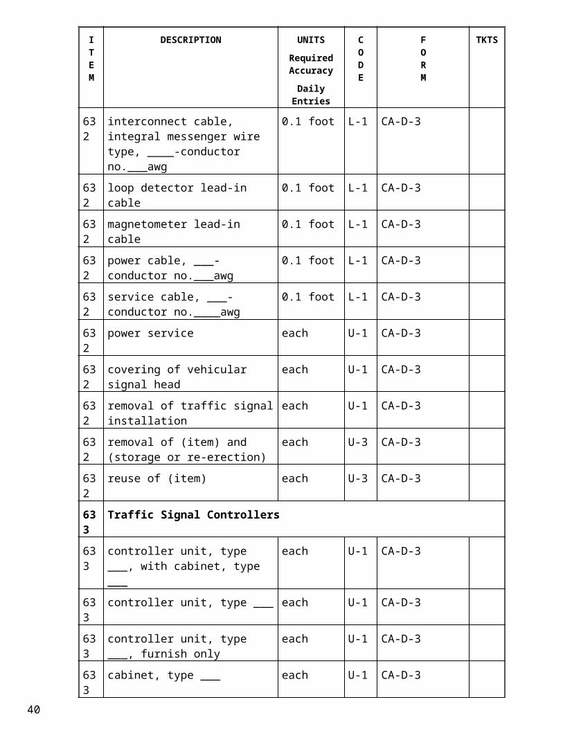
632 interconnect cable, integral messenger wire type, ____-conductor no.___awg
0.1 foot L-1 CA-D-3
632 loop detector lead-in cable 0.1 foot L-1 CA-D-3
632 magnetometer lead-in cable 0.1 foot L-1 CA-D-3
632 power cable, ___-conductor no.___awg
0.1 foot L-1 CA-D-3
632 service cable, ___-conductor no.____awg
0.1 foot L-1 CA-D-3
632 power service each U-1 CA-D-3
632 covering of vehicular signal head each U-1 CA-D-3
632 removal of traffic signal installation each U-1 CA-D-3
632 removal of (item) and (storage or re-erection)
each U-3 CA-D-3
632 reuse of (item) each U-3 CA-D-3
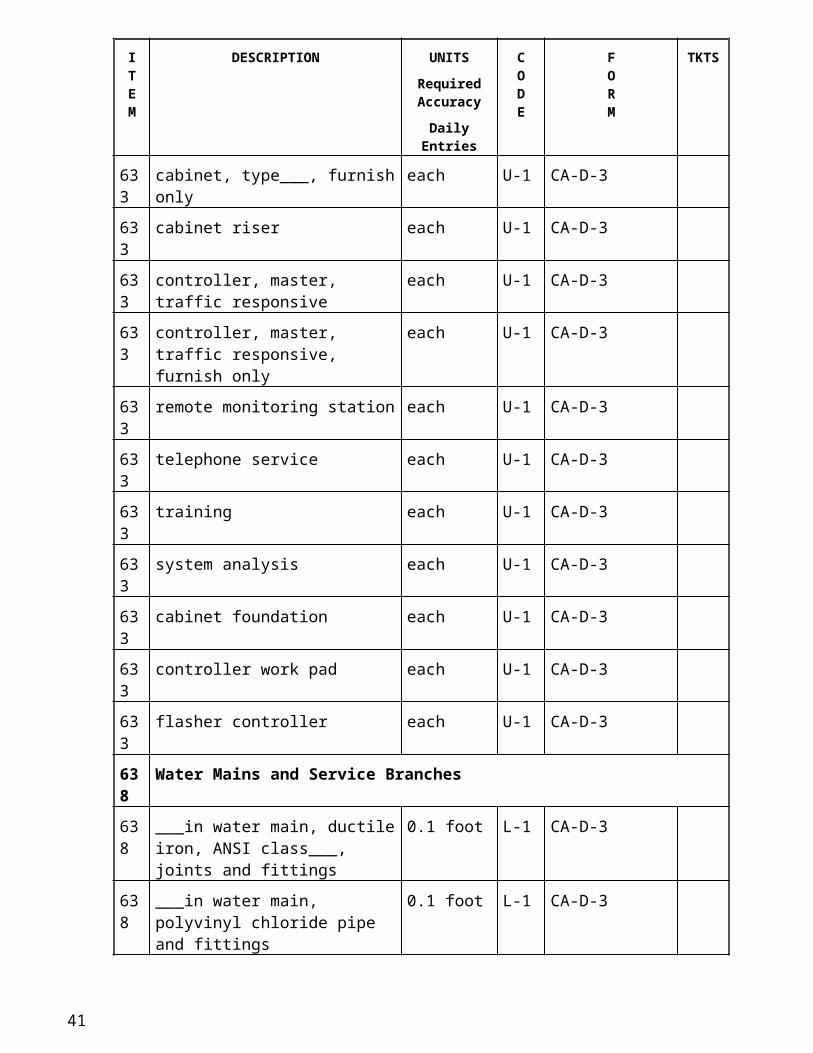
633 Traffic Signal Controllers
633 controller unit, type ___, with cabinet, type ___
each U-1 CA-D-3
633 controller unit, type ___ each U-1 CA-D-3
633 controller unit, type ___, furnish only each U-1 CA-D-3
633 cabinet, type ___ each U-1 CA-D-3
633 cabinet, type___, furnish only each U-1 CA-D-3
633 cabinet riser each U-1 CA-D-3
633 controller, master, traffic responsive each U-1 CA-D-3
633 controller, master, traffic responsive, furnish only
each U-1 CA-D-3
633 remote monitoring station each U-1 CA-D-3
633 telephone service each U-1 CA-D-3
633 training each U-1 CA-D-3
633 system analysis each U-1 CA-D-3
633 cabinet foundation each U-1 CA-D-3
633 controller work pad each U-1 CA-D-3
633 flasher controller each U-1 CA-D-324
ITEM
DESCRIPTION UNITSRequired Accuracy
Daily Entries
CODE
FORM
TKTS
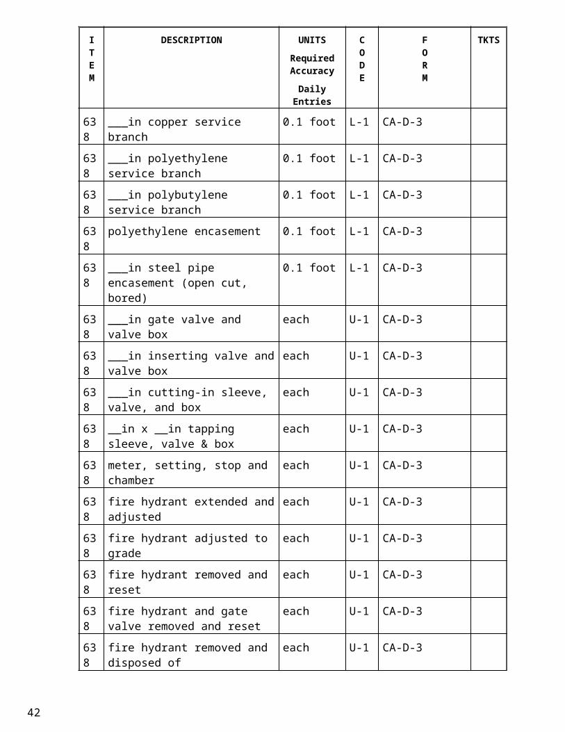
638 Water Mains and Service Branches
638 ___in water main, ductile iron, ANSI class___, joints and fittings
0.1 foot L-1 CA-D-3
638 ___in water main, polyvinyl chloride pipe and fittings
0.1 foot L-1 CA-D-3
638 ___in copper service branch 0.1 foot L-1 CA-D-3
638 ___in polyethylene service branch 0.1 foot L-1 CA-D-3
638 ___in polybutylene service branch 0.1 foot L-1 CA-D-3
638 polyethylene encasement 0.1 foot L-1 CA-D-3
638 ___in steel pipe encasement (open cut, bored)
0.1 foot L-1 CA-D-3
638 ___in gate valve and valve box each U-1 CA-D-3
638 ___in inserting valve and valve box each U-1 CA-D-3
638 ___in cutting-in sleeve, valve, and box
each U-1 CA-D-3
638 __in x __in tapping sleeve, valve & box
each U-1 CA-D-3
638 meter, setting, stop and chamber each U-1 CA-D-3
638 fire hydrant extended and adjusted each U-1 CA-D-3
638 fire hydrant adjusted to grade each U-1 CA-D-3
638 fire hydrant removed and reset each U-1 CA-D-3
638 fire hydrant and gate valve removed and reset
each U-1 CA-D-3
638 fire hydrant removed and disposed of each U-1 CA-D-3
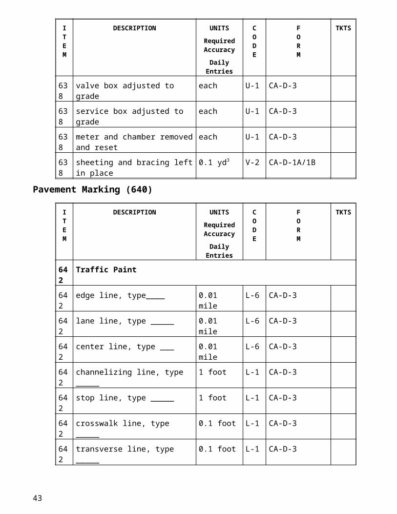
638 valve box adjusted to grade each U-1 CA-D-3
638 service box adjusted to grade each U-1 CA-D-3
638 meter and chamber removed and reset
each U-1 CA-D-3
638 sheeting and bracing left in place 0.1 yd3 V-2 CA-D-1A/1B
Pavement Marking (640)
25
ITEM
DESCRIPTION UNITSRequired Accuracy
Daily Entries
CODE
FORM
TKTS
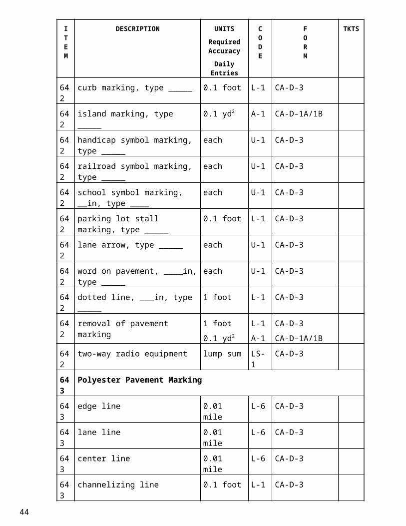
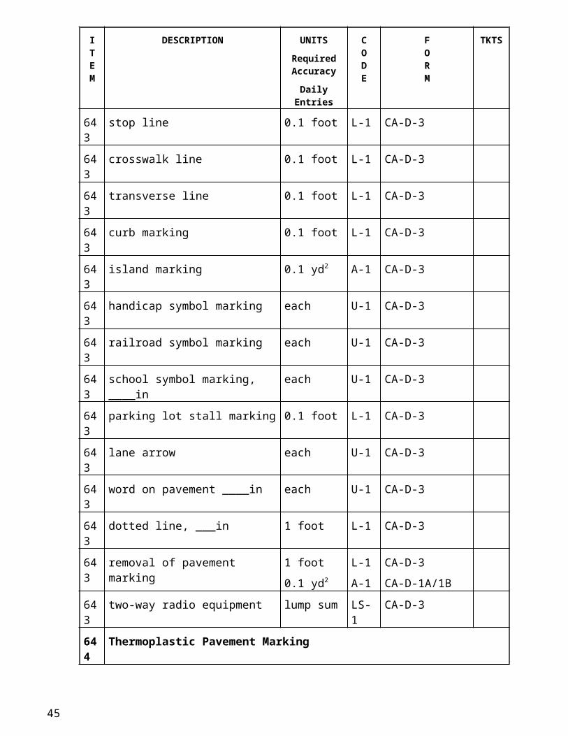
642 Traffic Paint
642 edge line, type____ 0.01 mile L-6 CA-D-3
642 lane line, type _____ 0.01 mile L-6 CA-D-3
642 center line, type ___ 0.01 mile L-6 CA-D-3
642 channelizing line, type _____ 1 foot L-1 CA-D-3
642 stop line, type _____ 1 foot L-1 CA-D-3
642 crosswalk line, type _____ 0.1 foot L-1 CA-D-3
642 transverse line, type _____ 0.1 foot L-1 CA-D-3
642 curb marking, type _____ 0.1 foot L-1 CA-D-3
642 island marking, type _____ 0.1 yd2 A-1 CA-D-1A/1B
642 handicap symbol marking, type _____
each U-1 CA-D-3
642 railroad symbol marking, type _____ each U-1 CA-D-3
642 school symbol marking, __in, type ____
each U-1 CA-D-3
642 parking lot stall marking, type _____ 0.1 foot L-1 CA-D-3
642 lane arrow, type _____ each U-1 CA-D-3
642 word on pavement, ____in, type _____
each U-1 CA-D-3
642 dotted line, ___in, type _____ 1 foot L-1 CA-D-3
642 removal of pavement marking 1 foot
0.1 yd2
L-1
A-1
CA-D-3
CA-D-1A/1B
642 two-way radio equipment lump sum LS-1 CA-D-3
643 Polyester Pavement Marking
643 edge line 0.01 mile L-6 CA-D-3
643 lane line 0.01 mile L-6 CA-D-3
643 center line 0.01 mile L-6 CA-D-3
643 channelizing line 0.1 foot L-1 CA-D-3
643 stop line 0.1 foot L-1 CA-D-3
643 crosswalk line 0.1 foot L-1 CA-D-3
643 transverse line 0.1 foot L-1 CA-D-3
643 curb marking 0.1 foot L-1 CA-D-3
643 island marking 0.1 yd2 A-1 CA-D-3
26
ITEM
DESCRIPTION UNITSRequired Accuracy
Daily Entries
CODE
FORM
TKTS
643 handicap symbol marking each U-1 CA-D-3
643 railroad symbol marking each U-1 CA-D-3
643 school symbol marking, ____in each U-1 CA-D-3
643 parking lot stall marking 0.1 foot L-1 CA-D-3
643 lane arrow each U-1 CA-D-3
643 word on pavement ____in each U-1 CA-D-3
643 dotted line, ___in 1 foot L-1 CA-D-3
643 removal of pavement marking 1 foot
0.1 yd2
L-1
A-1
CA-D-3
CA-D-1A/1B
643 two-way radio equipment lump sum LS-1 CA-D-3
644 Thermoplastic Pavement Marking
644 edge line 0.01 mile L-6 CA-D-3
644 lane line 0.01 mile L-6 CA-D-3
644 center line 0.01 mile L-6 CA-D-3
644 channelizing line 0.1 foot L-1 CA-D-3
644 stop line 0.1 foot L-1 CA-D-3
644 crosswalk line 0.1 foot L-1 CA-D-3
644 transverse line 1 foot L-1 CA-D-3
644 handicap symbol marking each U-1 CA-D-3
644 railroad symbol marking, ____in each U-1 CA-D-3
644 school symbol marking, ____in each U-1 CA-D-3
644 parking lot stall marking 0.1 foot L-1 CA-D-3
644 lane arrow each U-1 CA-D-3
644 word on pavement, ____in each U-1 CA-D-3
644 dotted line, _____in 1 foot L-1 CA-D-3
644 removal of pavement marking 1 foot
0.1 yd2
L-1
A-1
CA-D-3
CA-D-1A/1B
644 two-way radio equipment lump sum LS-1 CA-D-3
645 Preformed Pavement Marking
645 edge line, type_____ 0.01 mile L-6 CA-D-3
645 lane line, type_____ 0.01 mile L-6 CA-D-3
645 center line, type _____ 0.01 mile L-6 CA-D-3
27
ITEM
DESCRIPTION UNITSRequired Accuracy
Daily Entries
CODE
FORM
TKTS
645 channelizing line, type _____ 0.1 foot L-1 CA-D-3
645 stop line, type _____ 0.1 foot L-1 CA-D-3
645 crosswalk line, type _____ 0.1 foot L-1 CA-D-3
645 transverse line, type _____ 0.1 foot L-1 CA-D-3
645 handicap symbol marking, type _____
each U-1 CA-D-3
645 railroad symbol marking, type _____ each U-1 CA-D-3
645 school symbol marking, ___in, type ___
each U-1 CA-D-3
645 parking lot stall marking, type_____ 0.1 foot L-1 CA-D-3
645 lane arrow, type _____ each U-1 CA-D-3
645 word on pavement, ___in , type ___ each U-1 CA-D-3
645 dotted line, _____in, type _____ 1 foot L-1 CA-D-3
645 removal of pavement markings 1 foot
0.1 yd2
L-1
A-1
CA-D-3
CA-D-1A/1B
645 two-way radio equipment lump sum LS-1 CA-D-3
646 Epoxy Pavement Marking
646 epoxy pavement markings see items above
647 Heat-Fused Preformed Plastic Pavement Marking
647 heat-fused preformed plastic pavement markings
see items above
28
Roadsides (650)
ITEM
DESCRIPTION UNITSRequired Accuracy
Daily Entries
CODE
FORM
TKTS
651 Topsoil Stockpiled
651 topsoil stockpiled 1 yd3 V-3 CA-D-1A/1B
652 Placing Stockpiled Topsoil
652 placing stockpiled topsoil 1 yd3 V-5 CA-D-1A/1B
653 Topsoil Furnished and Placed
653 topsoil furnished and placed 1 yd3 V-5 CA-D-1A/1B
654 Renovating Existing Soil
654 renovation existing sod 1 ft2 A-1 CA-D-1A/1B
654 commercial fertilizer 0.01 ton W-4 CA-D-3
655 Seeding and Renovating Existing Sod
655 seeding and renovating existing sod 1 yd2 A-1 CA-D-1A/1B
655 commercial fertilizer 0.01 ton W-4 CA-D-3
656 Roadside Cleanup
656 roadside cleanup 1 ft2 A-1 CA-D-1A/1B
657 Riprap for Tree Protection
657 riprap for tree protection 1 yd2 A-1 CA-D-1A/1B
658 Tree Root Aeration
658 tree root aeration 1 yd3 V-5 CA-D-1A/1B
659 Seeding and Mulching
659 Commercial fertilizer 0.01 ton W-4 CA-D-3
659 Agricultural liming 0.01 ton W-4 CA-D-3
659 seeding and mulching 1 yd2 A-4 CA-D-1A/1B
659 seeding and mulching for wildlife 1 yd2 A-4 CA-D-1A/1B
659 repair seeding and mulching 1 yd2 A-1 CA-D-1A/1B
659 Water 1 m gal V-7 CA-D-3 X
659 Mowing 1 yd2 A-1 CA-D-1A/1B
660 Sodding
660 sodding unstaked 1 yd2 A-1 CA-D-1A/1B
660 sodding staked 1 yd2 A-1 CA-D-1A/1B
660 sodding reinforced 1 yd2 A-1 CA-D-1A/1B
29
ITEM
DESCRIPTION UNITSRequired Accuracy
Daily Entries
CODE
FORM
TKTS
661 Planting Trees, Shrubs, and Vines
661 tree seedling, (size), (species) each U-2 CA-D-3
661 perennials, (size), (species) each U-2 CA-D-3
661 ground cover , (size), (species) each U-2 CA-D-3
661 deciduous shrub , (size), (species) each U-2 CA-D-3
661 evergreen shrub, (size), (species) each U-2 CA-D-3
661 deciduous tree, (size), (species) each U-2 CA-D-3
661 evergreen tree, (size), (species) each U-2 CA-D-3
662 Landscape Watering
662 landscape watering gallon V-7 CA-D-3 X
664 Planting Salvaged Plants
664 planting salvaged plants each U-2 CA-D-3
665 Large Trees Moved and Reset
665 large trees moved and reset each U-2 CA-D-3
665 aggregate for drain pits and tree holes
0.1 yd3 V-2 CA-D-1A/1B
666 Pruning Existing Trees
666 pruning existing trees __in to __in dia.
each U-2 CA-D-3
667 Seeding and Jute Matting
667 seeding and jute matting 0.1 yd2 A-1 CA-D-1A/1B
668 Seeding and Excelsior Matting
668 seeding and excelsior matting 0.1 yd2 A-1 CA-D-1A/1B
670 Erosion Protection
670 slope erosion control 0.1 yd2 A-1 CA-D-1A/1B
670 ditch erosion control 0.1 yd2 A-1 CA-D-1A/1B
671 Temporary Erosion Control Mats
671 seeding and paper blanket 0.1 yd2 A-1 CA-D-1A/1B
672 Seeding and Mulching with Erosion Control Netting
672 seeding and mulching w/ erosion control netting
0.1 yd2 A-1 CA-D-1A/1B
673 Seeding and Erosion Control Blanket
673 seeding and erosion control blanket 0.1 yd2 A-1 CA-D-1A/1B
30
List of Forms
CA-S-1 Inspection Record for Drilled Shafts...................................................................................................................................33CA-S-2 Paint Thickness (QCP #5, #8, #10).....................................................................................................................................35CA-S-3 (BR-2-75) Pile Driving Log................................................................................................................................................37CA-S-3A (BR-2-75A) Pile Driving Log Summary........................................................................................................................39CA-S-4 High Performance Concrete Pre-Pour Meeting - 1/3.........................................................................................................41CA-S-4 High Performance Concrete Pre-Pour Meeting - 2/3..........................................................................................................42CA-S-4 High Performance Concrete Pre-Pour Meeting - 3/3..........................................................................................................43CA-S-5 Micro-Silica Overlay Pre-Pour Meeting - 1/3.....................................................................................................................45CA-S-5 Micro-Silica Overlay Pre-Pour Meeting - 2/3.....................................................................................................................46CA-S-5 Micro-Silica Overlay Pre-Pour Meeting - 3/3.....................................................................................................................47CA-S-6 Class S Concrete Pre-Pour Meeting - 1/2...........................................................................................................................49CA-S-6 Class S Concrete Pre-Pour Meeting - 2/2...........................................................................................................................50CA-S-7 QCS Inspection Documentation..........................................................................................................................................51CA-S-8 (BR-5) Piling Record...........................................................................................................................................................53CA-S-9 Reinforcing Steel Verification.............................................................................................................................................55CA-S-11 QCS & Visual Standards Information.................................................................................................................................57CA-S-12 Bridge Painting Quality Control Points (QCP #1 & #2).....................................................................................................59CA-S-13 Abrasive Blasting (QCP#3).................................................................................................................................................61CA-S-14 Disposal of Hazardous / Non- Hazardous Waste for Bridge Painting (QCP#4).................................................................63CA-S-15 Prime Coat Application (QCP#5)........................................................................................................................................65CA-S-16 Bridge Painting: Grinding Fins, Tears, and Slivers; and Caulking (QCP #6 & #9)............................................................67CA-S-17 Intermediate & Finish Coat Application (QCP #8 & #10)..................................................................................................69CA-S-17 Intermediate & Finish Coat Application (QCP #8 & #10) (back).......................................................................................70CA-S-18 Bridge Painting Destructive Test Log (QCP #11)...............................................................................................................71CA-S-19 Bridge Painting Final Review (QCP #11)...........................................................................................................................73CA-S-20 Erection (Demolition) Procedure Checklist........................................................................................................................75CA-S-21 Sealing of Concrete Surfaces Checklist...............................................................................................................................77TE-45 Concrete Inspectors Daily Report........................................................................................................................................79CA-C-1 Concrete Control Test Form................................................................................................................................................81CA-EW-1 Earthwork Quantity Calculations....................................................................................................................................83CA-EW-2 Proof Rolling Documentation.........................................................................................................................................85CA-EW-3 Log of Test Pit Investigation..........................................................................................................................................87CA-EW-4 Moisture Density Curve Calculation..............................................................................................................................89CA-EW-5 Nuclear Gauge Compaction Form..................................................................................................................................91CA-EW-6 Nuclear Gauge Compaction with Aggregate Correction................................................................................................93Typical Moisture Density Curves - Set C - May, 1949..........................................................................................................................94Zero Air Voids Curve.............................................................................................................................................................................96CA-EW-8 Authorization of Undercuts............................................................................................................................................97CA-EW-9 Rock Blasting Inspection Form......................................................................................................................................99CA-EW-10 Rock Blasting Drilling Log...........................................................................................................................................101CA-EW-11 Blast Site Security Plan.................................................................................................................................................103CA-EW-12 Daily Earthwork Inspection Form................................................................................................................................105CA-EC-1 Weekly and Rain Event Checklist.................................................................................................................................107CA-EC-2 Seeding Calculations.....................................................................................................................................................109CA-FP-1 Warranty Asphalt Checklist...............................................................................................................................................111CA-FP-2 Random Selection of Asphalt Field Samples (448, 403).................................................................................................113CA-FP-3 Summary of Asphalt Concrete Quantities.........................................................................................................................115CA-FP-4 Asphalt Concrete inspection..............................................................................................................................................117CA-FP-5 Roller Capacity and Placement Rate.................................................................................................................................119CA-FP-6 Calculation of Liquid Asphalt Materials...........................................................................................................................121TE-217 Bituminous Concrete Density Determination - 446 Cores................................................................................................123TE-217 Bituminous Concrete Density Determination - 446 Form Instructions.............................................................................125TE-217 Bituminous Concrete Density Determination - 446 Random Number Table...................................................................127CA-P-1 Pipe Construction Inspection Form - 1/2...........................................................................................................................129CA-P-1 Pipe Construction Inspection Form 2/2............................................................................................................................130CA-P-2 Underdrain Construction Inspection Form 1/2..................................................................................................................131CA-P-2 Underdrain Construction Inspection Form 2/2..................................................................................................................132
31
CA-P-3 Drainage Structure Inspection Form 1/2...........................................................................................................................133CA-P-3 Drainage Structure Inspection Form 2/2...........................................................................................................................134CA-D-1A Field Calculation and Measurement.............................................................................................................................135CA-D-1B Field Calculation and Measurement.............................................................................................................................137CA-D-2 Field Calculation and Measurement..................................................................................................................................139CA-D-3A ODOT Inspectors Daily Report....................................................................................................................................141CA-D-3B ODOT Inspectors Daily Report....................................................................................................................................143CA-D-4 ODOT P.E. / P.S. Daily Report.........................................................................................................................................145CA-D-5 Daily Account of Force Account Work.............................................................................................................................147CA-D-6 Pavement Repair and Sawing Measurement.....................................................................................................................149CA-D-7 Short Term Work Zone Review........................................................................................................................................151CA-D-8 Long Term Work Zone Review - 1/2................................................................................................................................153CA-D-8 Long Term Work Zone Review - 2/2..............................................................................................................................154CA-D-9 Daily Concrete Pavement Documentation Form - 1 / 5.................................................................................................155CA- D-9 Daily Concrete Pavement Documentation Form - 2 / 5.................................................................................................156CA- D-9 Daily Concrete Pavement Documentation Form - 3 / 5.................................................................................................157CA- D-9 Daily Concrete Pavement Documentation Form - 4 / 5.................................................................................................158CA- D-9 Daily Concrete Pavement Documentation Form - 5 / 5.................................................................................................159CA-L-1 Report of Electrical Tests..................................................................................................................................................161CA-L-2 Report of Electrical Tests..................................................................................................................................................163CA-L-3 Report of Electrical Tests..................................................................................................................................................165CA-L-4 Report on Sign Lighting....................................................................................................................................................167CA-L-5 Report on High Voltage Direct Current Tests...................................................................................................................169CA-T-1 DLS Report Format - Weight-Based System....................................................................................................................171CA-T-2 DLS Short Report Format - Weight-Based System...........................................................................................................172CA-T-3 DLS Report Format – Stroke Counter System..................................................................................................................173CA-T-4 DLS Short Report Format – Stroke Counter System........................................................................................................174CA-T-5 DLS Report Format – Flow Meter Based System.............................................................................................................175CA-T-6 DLS Short Report Format – Flow Meter Based System...................................................................................................176CA-T-7 DLS Report Format – ThermoPlastic System...................................................................................................................177CA-T-8 DLS Short Report Format – ThermoPlastic System.........................................................................................................178TE-31 Sample Data.......................................................................................................................................................................179Noise Barrier Wall Shop Drawing Review Checklist..........................................................................................................................183Preconstruction Meeting Agenda / Checklist.......................................................................................................................................184
32
CA-S-1 Inspection Record for Drilled Shafts
Project No: Bridge No: SFN:
Drilling Contractor: Project Engineer: Date:
Type of Equipment: Inspector: Item No:
Max Continuous Torque (FtLb)(Nm): Cost Above Rock($/LF):
CROWD (Max cont. Downward Force )-(Lbs)(N): Cost in Rock($/LF):
Cost of Concrete pumping($/LF): Type of Rock:
Drilled Shaft Number: Units
Date & Time of Drilling
StartedDate
Time
FinishedDate
Time
Elevation of Top of Overburden Ft (m)
Length of Drilled Shafts above Bedrock Socket
Through air Ft (m)
Through Overburden Ft (m)
Pay Length Ft (m)
Obstructions Encountered
Number -
Size Ft (m)
Time of Removal Hours
Length of Drilled Shaft in the Rock Socket
Elev. Top of Socket Ft (m)
Elev. Bottom of Socket Ft (m)
Length of Socket Ft (m)
Steel CasingCasing Thickness In(mm)
Casing Left in Place Ft (m)
Reinforcing Steel
VerticalBar Size Number ---
No. of Bars ---
SpiralBar Size Number ---
Pitch In(mm)
Concrete
Slump In(mm)
Cylinder Strength PSI(MPa)
Air Temp F(C)
Time to Place Concrete Hr
TolerancesDeviations from Plumb
N-S In(mm)
E-W In(mm)
Deviations of column top center from plan In(mm)
Plan Shaft Diameter (Bedrock / Overburden) In(mm)
Constructed Diameter (Bedrock / Overburden) In(mm)
CA-S-1 Inspection Record for Drilled Shafts (back)
ODOT Form date: 7/1/2009
CA-S-2 Paint Thickness (QCP #5, #8, #10)CA-S-2D10, 01-07
Project No: Bridge No: Date:
Ref No: Item No:
Inspector Signature:Coat:Inspection Location:
Sum of Spot Averages=
Area Average(Sum of Spot Averages/5)=
Span/Beam Line
Reading #1
Reading #2
Reading #3
Total of 3 Readings:
Spot Average (Total / 3):
Sum of Spot Averages=
Area Average(Sum of Spot Averages/5)=
Area Average(Sum of Spot Averages/5)=
Sum of Spot Averages=
Area Average(Sum of Spot Averages/5)=
Sum of Spot Averages=
Span/Beam Line
Reading #1
Bridge Area = 1001 to Infinity (CMS 514.20.C)
Bridge Area = 301 - 1000(CMS 514.20.B)
2100119001 2000114001 15001 16001 17001 18001
9001 10001 11001 120016001 7001 8001 13001
4001 5001
Spot Average (Total / 3):
Total of 3 Readings:
Reading #2
Reading #3
301 - 1000 1001 2001 3001
Paint Thickness
Bridge Area = 0 - 300(CMS 514.20.A)
Prime Intermediate FinishTop Flange Bottom Flange Web Cross Bracing Stiffener Other
ODOT Form date: 7/1/2009
CA-S-2 Paint Thickness (QCP #5, #8, #10) (back)
Bottom Section:
Middle Section:
Top Section: This section is used for general information.
This section is to help you determine how many 100 square foot areas must be tested. See CM&S 514.20
This section is used to calculate and record the dry film thickness (DFT) readings on a member in a particular area. The spot averages should be compared to the minimum and maximum spot thinknesses given in the table in CM&S 514.20. The Area Averages should be compared to the minimum and maximum specified thicknesses given in the table in CM&S 514.20
ODOT Form date: 7/1/2009
CA-S-3 (BR-2-75) Pile Driving Log
ODOT Form date: 7/1/2009
Project No: County/Route/Section:
Bridge No: Object Bridge Over:
SFN: Date:
Substructure Unit: Date Driven: Pile Number:
Pile Type: Wall Thickness: Hammer:
Required Ultimate Bearing: Batter: Drop Hammer Ram Weight:
Cutoff Elevation: Ground Elevation: No. of Splices:
Penetration Blows /Ft Stroke or Pressure Penetration Blows/Ft Stroke or
Pressure Remarks
Inspectors Name: Signature:
CA-S-3 (BR-2-75) Pile Driving Log (back)
ODOT Form date: 7/1/2009
CA-S-3A (BR-2-75A) Pile Driving Log Summary
ODOT Form date: 7/1/2009
CA-S-3A (BR-2-75A) Pile Driving Log Summary (back)
ODOT Form date: 7/1/2009
CA-S-4 High Performance Concrete Pre-Pour Meeting - 1/3
PROJECT: ____________________________________________ DATE: ___________________
LOCATION: ________________________________________ TIME: ___________________
PRESENT: ____________________________________________________________________________________
___________________________________________________________________________________
_____________________________________________________________________________________
DRY RUN:
‒ Check height of rail over enddams at all four corners - *Equal heights for left rear and fwd and for right rear and fwd
‒ Check any change in cross-slope and discuss method of performance
– Confirm appropriate depth of roller fins
– Check reinforcing steel clearances
TIME AND LOCATION OF POUR:
‒ Date: __________________ Time:__________________
‒ Pour to begin on __________________ side and commence on the __________________ side
‒ Location of pumps, if used
‒ Lighting plan if at night
PLAN AND SPECIFICATION REVIEW:
‒ Need a written statement, from the admixture supplier verifying the compatibility of materials, a mix design, and a batching sequence
‒ Need successful test pour prior to concrete placement
‒ A technical representative is required during concrete placement
‒ Calendar restrictions for flyash are waived
‒ Need verification of vibration frequencies on finishing machine
‒ No rain to be forecasted during placement; if rain occurs, operations cease
‒ Surface evaporation rate must be equal to or less than 0.1 pound per square foot per hour DURING the pour as determined and documented by the contractor
‒ Vibrators shall be used
‒ Mix characteristics shall be adjusted off the deck before placement
‒ Maximum mix temperature is 90 degrees
‒ 7 day water cure: 1 layer of burlap with continuous water covered with plastic sheeting, apply membrane cure as per 511.19 method (b) within 12 hours of burlap removal
‒ Prior to opening to traffic, check top and bottom for cracks and, if necessary, reseal from the top
‒ Can open to traffic after membrane cure is applied, unless between October 15 and March 30, then must wait 30 days
– Seal joints with HMWM
– Re-apply membrane cure after grooving, unless concrete is older than 30 days
ODOT Form date: 7/1/2009
CA-S-4 High Performance Concrete Pre-Pour Meeting - 2/3
PROJECT: __________________________________________ DATE: ___________________
CONCRETE PLANT:
‒ Presoak limestone 24 hours and allow to drain overnight - *Don’t charge bins with dry material
‒ Batching to begin at _____________
‒ Expel all water from the mixers before loading / reloading (especially important for micro-silica mixes)
‒ Dissolvable micro-silica bags are not allowed
‒ A slow ribbon feed of cement is required
‒ Mix 5 minutes at plant
‒ Pour consists of approximately _____________ C.Y.
‒ Time between trucks _____________ minutes
‒ Pour _____________ cy./hr.
‒ Radio communication with plant for mix design changes
‒ Haul distance: _____________ minutes
QUALITY CONTROL
‒ High Performance Concrete
‒ Mix no. _____________
‒ Proportioning and batching changes are contractor’s responsibility
‒ W/C max = 0.40, (mix 3 and 4), based on total cementitious material
‒ Maximum slump = 8 inches
‒ Air 7% ± 2
‒ Flyash, unless use slag, shall be type C
‒ Type F or G admixture is required for workability; suggest using type A for finishing advantages
‒ Any admixtures added at the jobsite shall be mixed a minimum of 5 minutes
‒ Air and slump tests are to be taken at point of placement
‒ Discharge time = 90 minutes
– No “balling” of mix, if balling occurs load will be rejected and mixing process revised
CONTRACTOR’S OPERATION
‒ Tools
* broom finish
* vibrating pan or rollers
* straightedge
* presoaked burlap
* plastic for bad weather protection
* extra vibrator
ODOT Form date: 7/1/2009
CA-S-4 High Performance Concrete Pre-Pour Meeting - 3/3
PROJECT: _____________________________________________ DATE: ___________________
CONTRACTOR’S OPERATION (Continued)
‒ Concrete Placement
* wet deck continuously in front of placement
* place plastic sheeting to avoid deck contamination
* straightedge checking at bulkheads and enddams
* need 2 walk-bridges (1 for finishers and 1 for burlap)
* smooth finish along curbs and/or parapets only
* burlap shall follow as close as possible to deck overlay
PROJECT INSPECTION Personnel (If available)
‒ Moisture tests to be run at _____________
‒ 1 Plant Inspector
* Checking aggregate moistures
* checking revolutions
* checking no wash water, no wash down water after batching
‒ 2 Concrete Quality Control Testers __________________________
* chase air on every truck _____________
* Air, slump, yield
* Cylinders made every 200 CY.
* various pump, if used, configuration correlation tests
* make beams
* check concrete temperature
‒ 1 Concrete Quality Control Inspector __________________________
* documenting any added materials
* check batch tickets
* time from start to discharge
* insuring 5 minute mixing time if materials added
* documenting test results
* fill out TE-45
‒ 1 Placement Inspector __________________________
* make depth checks
* make reinforcing steel depth checks
* insure curing is placed ASAP
MISCELLANEOUS
‒ Traffic Control
ODOT Form date: 7/1/2009
CA-S-4 High Performance Concrete Pre-Pour Meeting - 3/3 (back)
ODOT Form date: 7/1/2009
CA-S-5 Micro-Silica Overlay Pre-Pour Meeting - 1/3
PROJECT: ____________________________________________________ DATE: ___________________
LOCATION: __________________________________________________ TIME: ___________________
PRESENT: ___________________________________________________________________________________
______________________________________________________________________________________________
______________________________________________________________________________________________
DRY RUN:
‒ Check height of rail over enddams at all four corners - *Equal heights for left rear and fwd and for right rear and fwd
‒ Check any change in cross-slope and discuss method of performance
– Confirm appropriate depth of roller fins
TIME AND LOCATION OF POUR:
‒ Date: __________________ Time:__________________
‒ Pour to begin on __________________ side and commence on the __________________ side
‒ Lighting plan if at night
PLAN AND SPECIFICATION REVIEW:
‒ The Contractor shall obtain a written statement from the manufacturer of the micro-silica admixture stating that he is satisfied with the compatibility of the combination of materials and the sequence in which they are combined.
‒ At the option of the laboratory, a trial batch may be made (4) four days prior to overlay
‒ Manufacturer representative shall be present during overlay
‒ No micro-silica overlays after October 15
‒ No rain to be forecasted during placement; if rain occurs, operations cease
‒ Air temperature must be below 85 degrees and not predicted to go over during concrete placement
* Must be a minimum of 45 degrees during placement and curing period
‒ Surface evaporation rate must be equal to or less than 0.1 pound per square foot per hour as determined and documented by the contractor
‒ Wet deck prior to concrete placement but no ponding
‒ Mix characteristics shall be adjusted off the deck before placement of the overlay
‒ Maximum mix temperature is 90 degrees
‒ Vibrators shall be used in variable depth areas, edges and along enddams or bulkheads
‒ During short delays, overlay and grout shall be covered with wet burlap
*Excess delays require bulkheads
‒ 3 day water cure: 1 layer of burlap with continuous water covered with plastic sheeting
‒ Contractor to stencil date of construction and the letters MS into the overlay
‒ Deck to be sounded after overlay to insure no delaminated areas
ODOT Form date: 7/1/2009
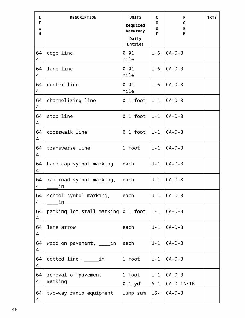
CA-S-5 Micro-Silica Overlay Pre-Pour Meeting - 2/3
PROJECT: ____________________________________________ DATE: ___________________
CONCRETE PLANT:
‒ Presoak limestone 24 hours and allow to drain overnight *Don’t charge bins with dry material
‒ Batching to begin at ________________
‒ Expel all water from the mixers before loading / reloading
‒ Add super on jobsite if long haul distance
‒ Minimum of 70 revolutions on mixers before leaving plant unless central mixed
‒ Pour consists of approximately ________________ CY
‒ Time between trucks ________________ minutes
‒ Pour ________________ cy./hr.
‒ Radio communication with plant for mix design changes
‒ Haul distance: ________________ minutes
QUALITY CONTROL
‒ Modified micro-silica concrete
‒ W/C max = 0.36
‒ Slump 6 inches ± 2
‒ Air 8% ± 2
‒ Type A or D and F admixture shall be used
‒ Transit mixers are limited to carrying ¾ of its rated capacity or 6 cy whichever is less
‒ Any admixtures added at the jobsite shall be mixed a minimum of 5 minutes
‒ Discharge time = 90 minutes
CONTRACTOR’S OPERATION
‒ Tools
* broom finish, * vibrating pan or roller, * straightedge, * presoaked burlap
* plastic for bad weather protection, * extra vibrator
‒ Concrete Placement
* abrasive or water blast deck within 24 hours of overlay
* air blast deck immediately before overlay
* place plastic sheeting to avoid deck contamination
* straightedge checking at bulkheads and enddams
* need 2 walk-bridges (1 for finishers and 1 for burlap)
ODOT Form date: 7/1/2009
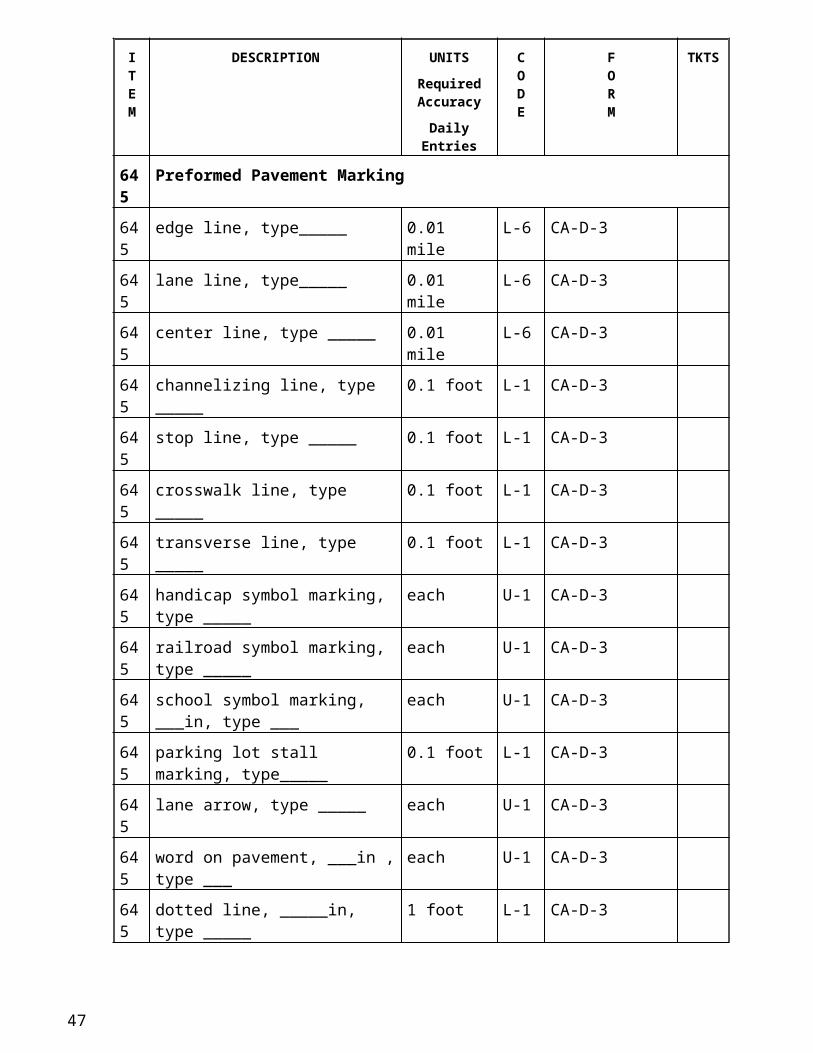
CA-S-5 Micro-Silica Overlay Pre-Pour Meeting - 3/3
PROJECT: ________________________________________ DATE: ___________________
PROJECT INSPECTION Personnel (If available)
‒ Moisture tests to be run at _______________ followed by design of the mix.
‒ 1 Plant Inspector ____________________________
* check moistures
* checking revolutions
* checking no wash water
‒ 2 Concrete Control Testers _____________________________
* full test on every truck ______________________________
* Cylinders as required every 50 CY
* check concrete temperature
‒ 1 Concrete Quality Control Inspector _____________________________
* documenting any added materials
* check batch tickets
* time from start to discharge
* insuring 5 minute mixing time if materials added
* documenting test results
* fill out TE-45
‒ 1 Placement Inspector _____________________________
* make depth checks
* Ensure curing is placed ASAP
MISCELLANEOUS
‒ Traffic Control
ODOT Form date: 7/1/2009
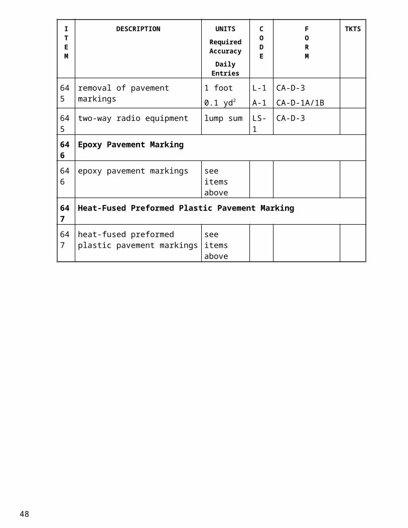
CA-S-5 Micro-Silica Overlay Pre-Pour Meeting - 3/3 (back)
ODOT Form date: 7/1/2009
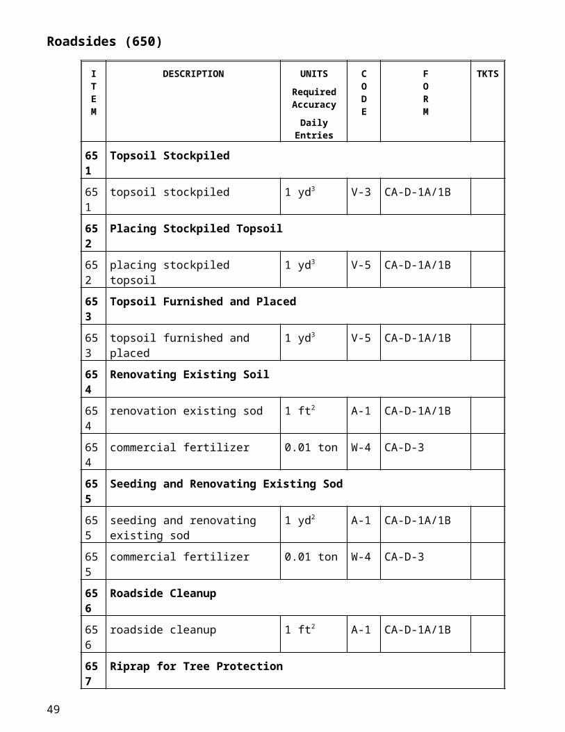
CA-S-6 Class S Concrete Pre-Pour Meeting - 1/2
PROJECT: _____________________________________________________ DATE: ___________________
LOCATION: ___________________________________________________ TIME: ___________________
PRESENT: ________________________________________________________________________________________
__________________________________________________________________________________________________
__________________________________________________________________________________________________
DRY RUN: _________________
‒ Check height of rail over enddams at all four corners - *Equal heights for left rear and fwd and for right rear and fwd
‒ Check any change in cross-slope and discuss method of performance
– Confirm appropriate depth of roller fins
– Check reinforcing steel clearances
TIME AND LOCATION OF POUR:
‒ Date: __________________ Time:__________________
‒ Pour to begin on __________________ side and commence on the __________________ side
‒ Location of pumps, if used
‒ Lighting plan if at night
PLAN AND SPECIFICATION REVIEW:
‒ Air temperature must be below 85o and not predicted to go over during concrete placement
‒ Surface evaporation rate must be equal to or less than 0.2 lbs/sq. ft. per hour
‒ Must water cure: 2 layers of burlap with continuous water, or plastic coated/covered burlap with positive moisture seal.
– Cure (5) five days with beam test
CONCRETE PLANT:
‒ Presoak limestone 24 hours and allow to drain overnight
*Don’t charge bins with dry material
‒ Batching to begin at __________________
‒ Expel all water from the mixers before loading / reloading
‒ Add super on jobsite if long haul distance
‒ Minimum of 70 revolutions on mixers before leaving plant unless central mixed
‒ Pour consists of approximately __________________ C.Y.
‒ Time between trucks __________________ minutes
‒ Pour __________________ cy./hr.
‒ Radio communication with plant for mix design changes
‒ Haul distance:__________________ minutes
ODOT Form date: 7/1/2009
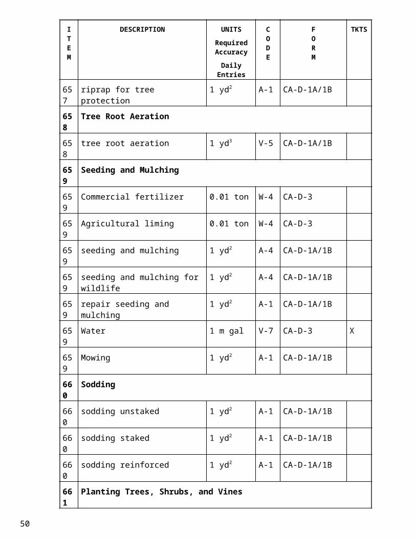
CA-S-6 Class S Concrete Pre-Pour Meeting - 2/2
PROJECT: ____________________________________________ DATE: ___________________
QUALITY CONTROL (Air and Slump tests to be checked at the point of Placement)
‒ Class S Concrete ‒ Slump 2-4 inches (6" nom. And 7" max. with addition of type F or G admixture)
‒ W/C max = 0.44 ‒ Type B or D admixture (retarder) to be used if over 60o F.
‒ Air 6% ± 2 ‒ Discharge time = 60 minutes (90 minutes with retarder)
CONTRACTOR’S OPERATION
‒ Tools
* broom finish, * vibrating pan or rollers, * straightedge, * wet burlap, * plastic for bad weather protection, * extra vibrator,
* weather gauges
‒ Concrete Placement
* air blast deck before pour
* wet forms before placement
* straightedge checking at bulkheads and enddams
* need 2 walk-bridges (1 for finishers and 1 for burlap)
* Groove as per 511.20
* smooth finish along curbs and/or parapets only
* wet burlap shall follow immediately after finishing
PROJECT INSPECTION Personnel (if available)
‒ Moisture tests to be run at ______________________________________
followed by design of the mix.
‒ 1 Plant Inspector: ______________________________________
* writing tickets, * checking revolutions, * checking no wash water
‒ 2 Concrete Control Testers ______________________________________
* chase air on every truck, * various pump, if used, configuration correlation tests
* make beams, * check concrete temperature
‒ 1 Concrete Quality Control Inspector ______________________________________
* documenting any added materials, * checking rev’s
* documenting test results, * fill out TE-45
‒ 1 Placement Inspector ______________________________________
* make depth checks, * make reinforcing steel depth checks
* insure curing is placed ASAP without marring surface
MISCELLANEOUS
‒ Traffic Control
ODOT Form date: 7/1/2009
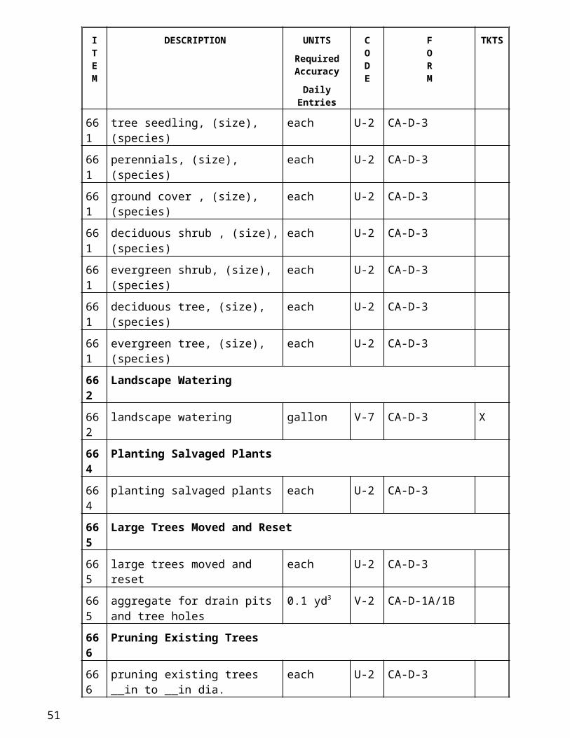
CA-S-7 QCS Inspection Documentation
ODOT Form date: 7/1/2009
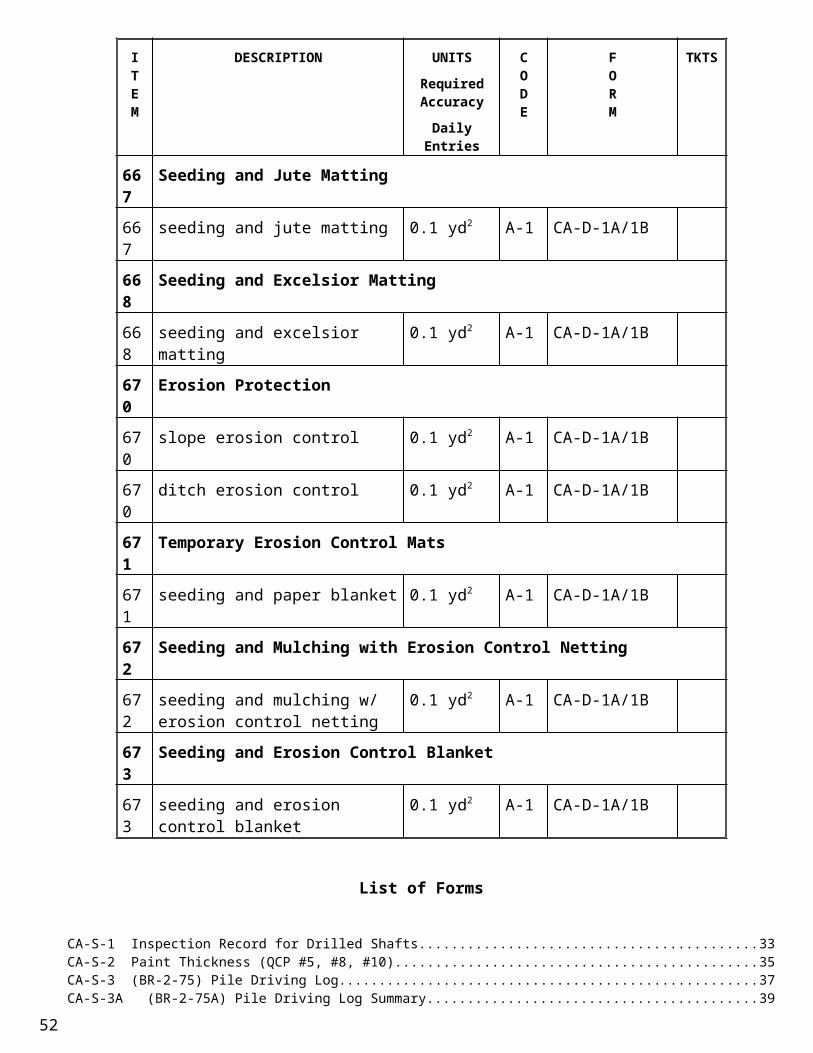
CA-S-7 QCS Inspection Documentation (back)
ODOT Form date: 7/1/2009
CA-S-8 (BR-5) Piling Record
Project No: County/Route/Section:
Bridge No: Object Bridge Over:
SFN: Date:
Substructure Unit: Date Driven: Hammer:
Pile Type: Required Resistance:
Required Ultimate Bearing: Batter: Drop Hammer Ram Weight:
Cutoff Elevation: Ground Elevation:
Pile Number Pile Length
Blows/Ft at end of Driving
Stroke or Pressure at end of
DrivingBatter No. of Splices Remarks
Inspectors Name: Signature:
ODOT Form date: 7/1/2009
CA-S-8 (BR-5) Piling Record (back)
ODOT Form date: 7/1/2009
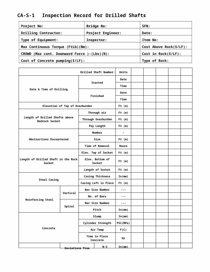
CA-S-9 Reinforcing Steel Verification
ODOT Form date: 7/1/2009
CA-S-9 Reinforcing Steel Verification (back)
ODOT Form date: 7/1/2009
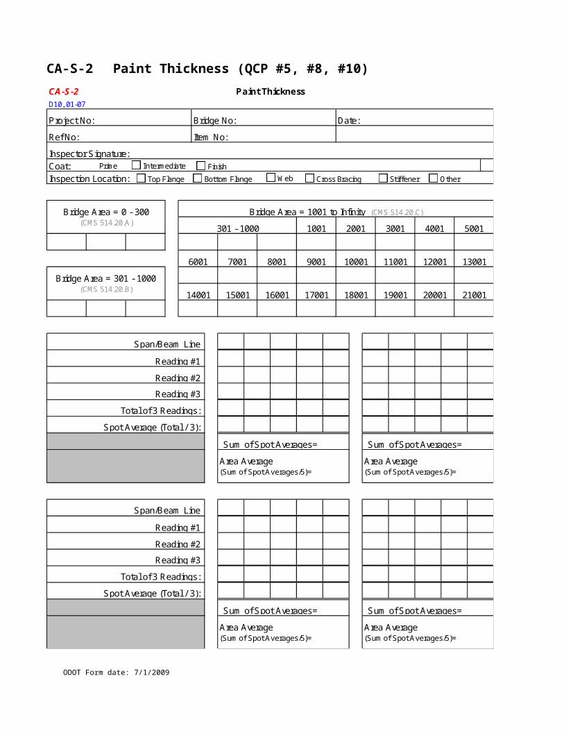
CA-S-11 QCS & Visual Standards Information
ODOT Form date: 7/1/2009
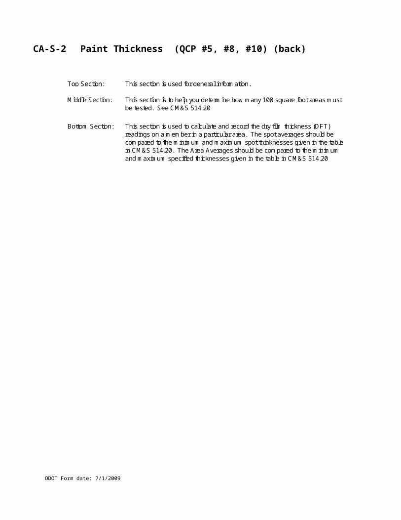
CA-S-11 QCS & Visual Standards Information (back)
ODOT Form date: 7/1/2009
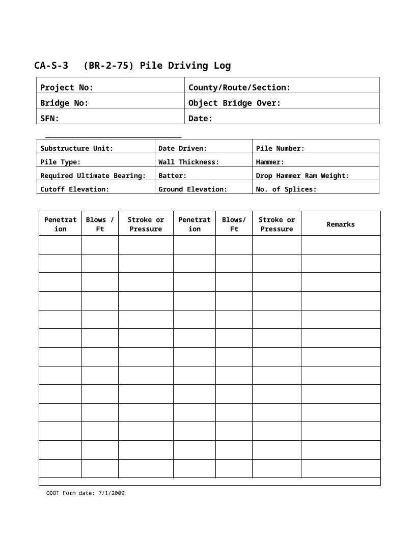
CA-S-12 Bridge Painting Quality Control Points (QCP #1 & #2)
ODOT Form date: 7/1/2009
CA-S-12 Bridge Painting Quality Control Points (QCP #1 & #2) (back)
ODOT Form date: 7/1/2009
CA-S-13 Abrasive Blasting (QCP#3)
ODOT Form date: 7/1/2009
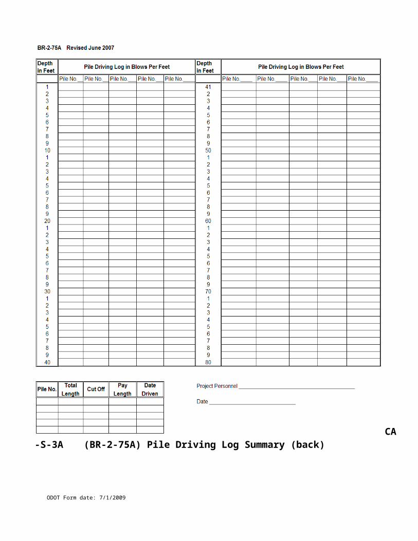
CA-S-13 Abrasive Blasting (QCP#3) (back)
ODOT Form date: 7/1/2009
CA-S-14 Disposal of Hazardous / Non- Hazardous Waste for Bridge Painting (QCP#4)
ODOT Form date: 7/1/2009
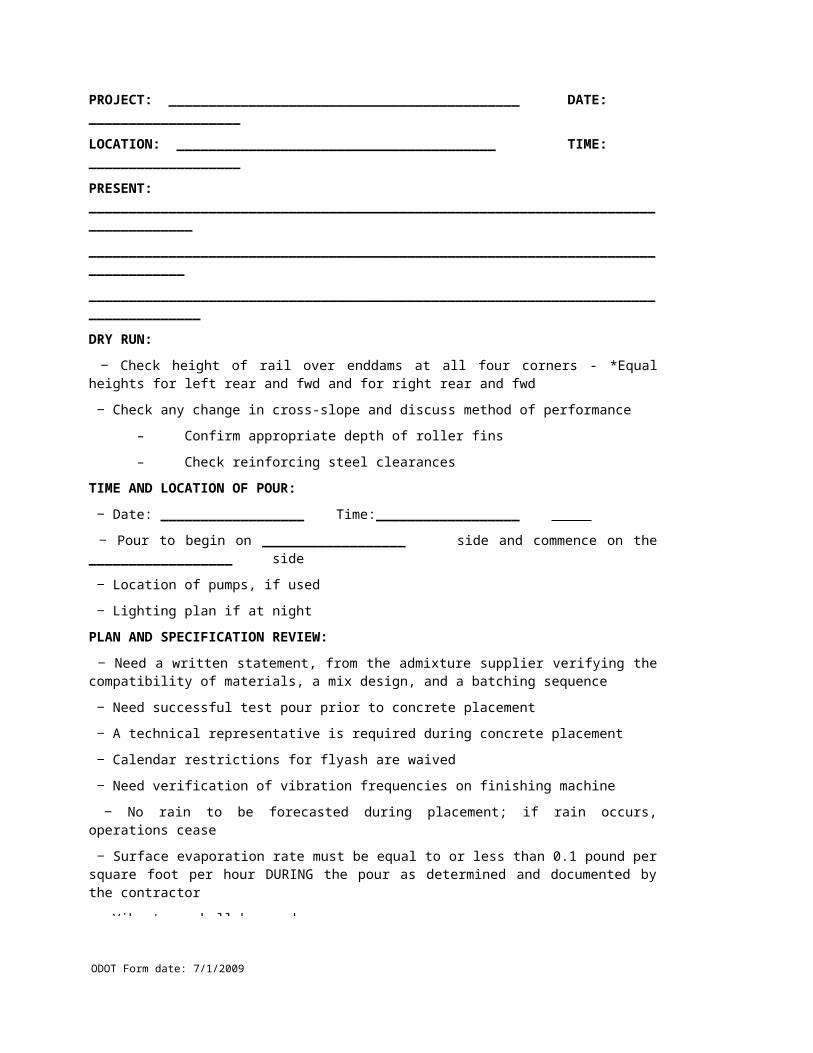
CA-S-14 Disposal of Hazardous / Non- Hazardous Waste for Bridge Painting (QCP#4) (back)
ODOT Form date: 7/1/2009
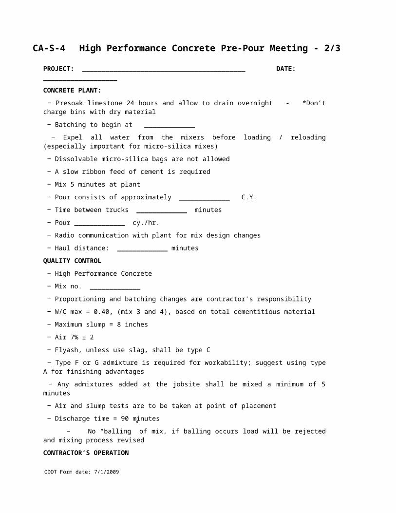
CA-S-15 Prime Coat Application (QCP#5)
ODOT Form date: 7/1/2009
CA-S-15 Prime Coat Application (QCP#5) (back)
ODOT Form date: 7/1/2009
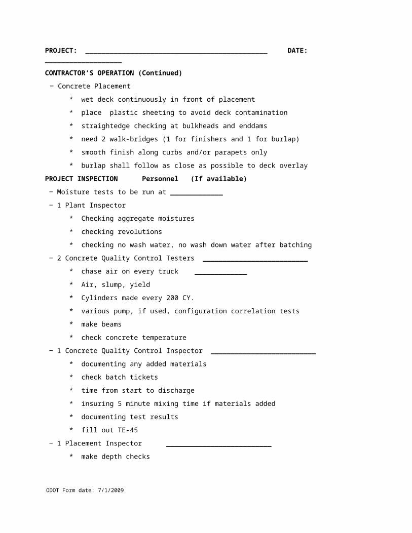
CA-S-16 Bridge Painting: Grinding Fins, Tears, and Slivers; and Caulking (QCP #6 & #9)
ODOT Form date: 7/1/2009
CA-S-16 Bridge Painting: Grinding Fins, Tears, and Slivers and Caulking (QCP #6 & #9) (back)
ODOT Form date: 7/1/2009
CA-S-17 Intermediate & Finish Coat Application (QCP #8 & #10)
ODOT Form date: 7/1/2009
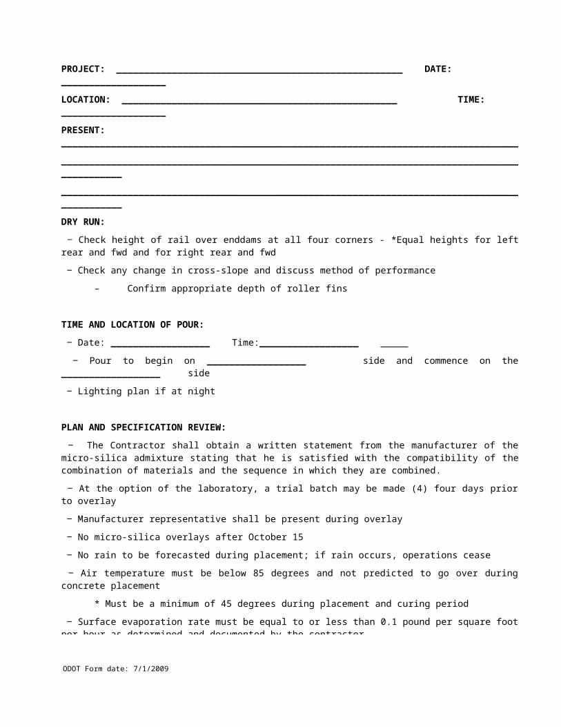
CA-S-17 Intermediate & Finish Coat Application (QCP #8 & #10) (back)
ODOT Form date: 7/1/2009
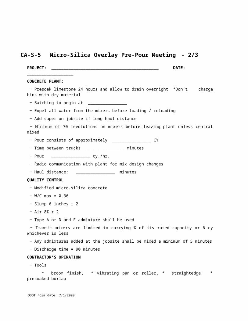
CA-S-18 Bridge Painting Destructive Test Log (QCP #11)
ODOT Form date: 7/1/2009
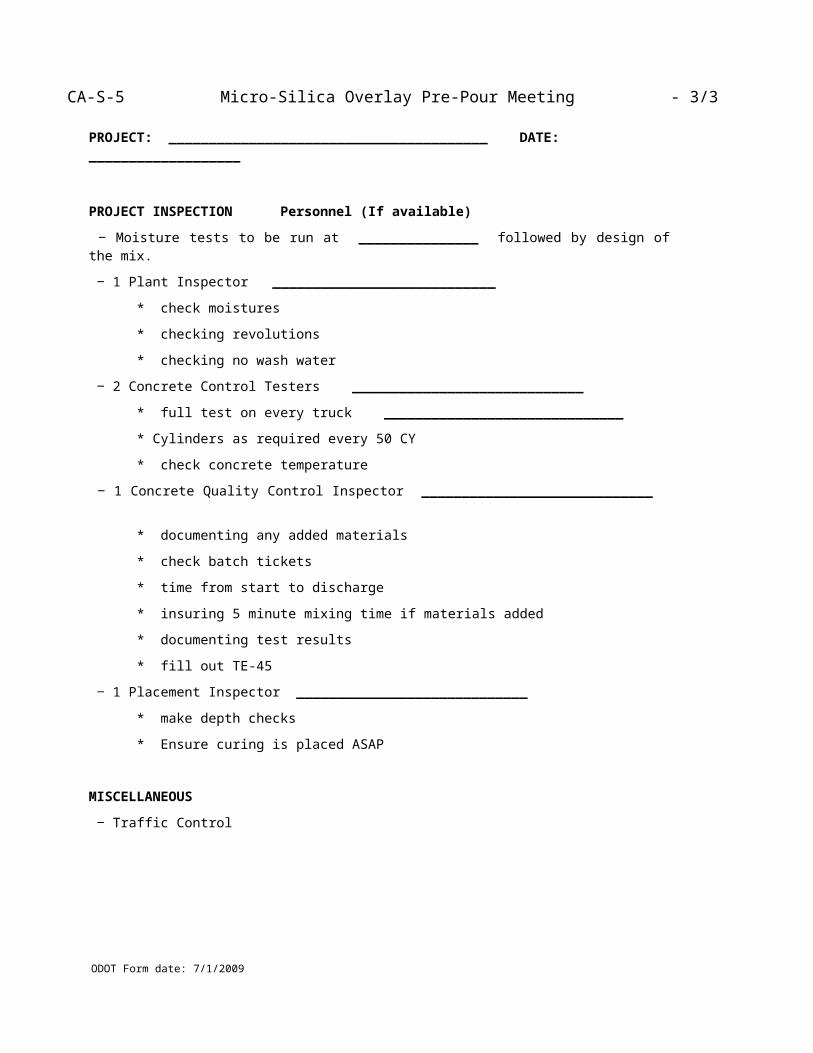
CA-S-18 Bridge Painting Destructive Test Log (QCP #11) (back)
ODOT Form date: 7/1/2009
CA-S-19 Bridge Painting Final Review (QCP #11)
ODOT Form date: 7/1/2009
CA-S-19 Bridge Painting Final Review (QCP #11) (back)
ODOT Form date: 7/1/2009
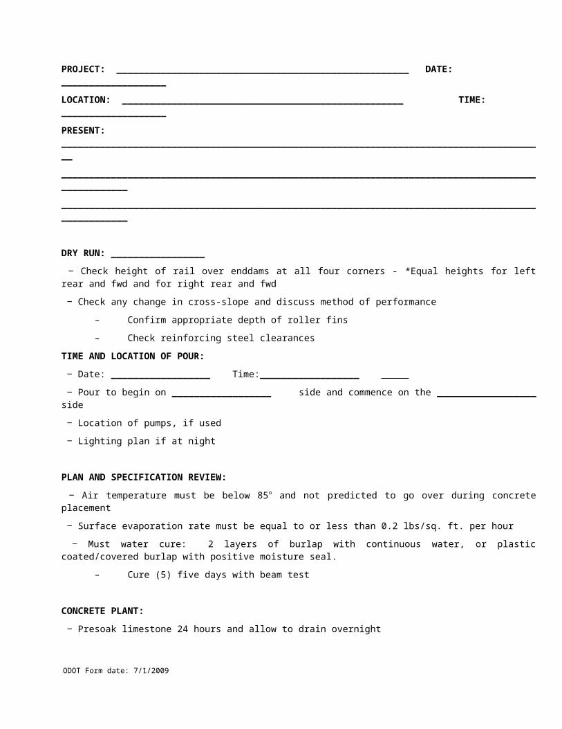
CA-S-20 Erection (Demolition) Procedure Checklist
ODOT Form date: 7/1/2009
Name (print clearly): ____________________________________________________________
Project: _________ Bridge (Co, Rt, Section): _________________________________________
Description: _____________________________________________________________________
Items Inspected:
Plan:
□ Contractor’s Erection (Demolition) Plan stamped by two PE’s.
□ Contractor’s Erection (Demolition) Plan accepted by regulatory agencies, Railroads, Coast Guard,
U.S. Army Corps of Engineers, etc., if applicable.
Details:
□ Erection (Demolition) sequence for all members.
□ Maintenance of Traffic during erection (demolition) operations.
□ Location of permanent support structures, roads, railroads, waterways, utilities.
□ Member delivery location and orientation for erection.
□ Member removal location and orientation for demolition.
□ Location and radius of each crane during each pick.
□ Location of crane support (barges, mats, etc.) , during each pick.
□ Crane capacities shown for each crane configuration and boom length used.
□ Lifting weights of primary member picks, including all rigging.
□ Rigging weights, capacities, and arrangements for primary member picks.
□ Locations of the centers of gravity and lifting points for primary members.
□ Temporary supports or bracing.
□ Blocking for bridge bearings.
Calculations:
□ Load capacity and stability of crane(s), temporary supports and rigging for each pick and release.
□ Structural adequacy and stability of members for each erection (demolition) step.
Signature: _______________________________________ Date: ___________
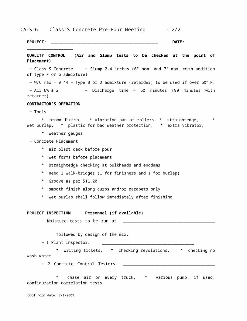
CA-S-20 Erection (Demolition) Procedure Checklist (back)
ODOT Form date: 7/1/2009
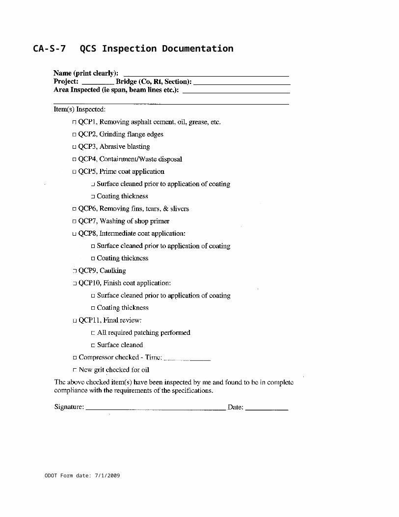
CA-S-21 Sealing of Concrete Surfaces Checklist
ODOT Form date: 7/1/2009
Name (print clearly): _________________________________________________________Project: _________ Bridge (Co, Rt, Section): ______________________________________Description: _________________________________________________________________Items Inspected:
Storage:
□ Thermometer to check for manufacturer’s acceptable range
□ Sealer stored not frozen nor in sun
□ Shelf life
Submittals made:
□ Technical and application data
□ Material Safety Data Sheet
□ 100 Grit Sandpaper supplied by Contractor for comparison
Equipment for proper preparation:
□ Correct water blast equipment (7000 psi minimum)
□ Correct abrasive blast equipment (followed by cleaning)
Equipment mixing and application:
□ Equipment meets manufacturer’s requirements:
Surface Preparation, clean concrete with 100 grit sandpaper texture:
□ Test site set up
□ Test all surfaces, (not just vertical)
□ Surface checked for texture
□ Acid Test performed if curing compound used
Mixing:
□ Material used within manufacturer’s shelf life □ Mix time and pot life marked
□ Mixed per manufacturer’s recommended procedures
Application:
□ Conditions acceptable
□ Material applied within pot life
□ Minimum coating rates met in test sections
▫ Epoxy – 120 Ft2/gal, (150 Ft2/gal if authorized)
▫ Urethane - 200 Ft2/gal,(even coverage, no skips or sags)
▫ Non-Epoxy – 100 Ft2/gal, Decks, 125 Ft2/gal, Vert. Surfaces
Signature: ____________________________________________ Date: ____________
CA-S-21 Sealing of Concrete Surfaces Checklist (back)
ODOT Form date: 7/1/2009
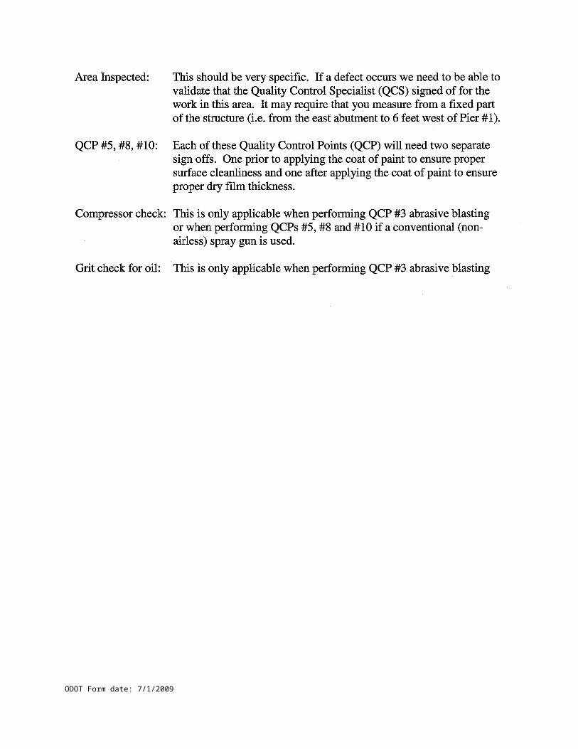
TE-45 Concrete Inspectors Daily Report
ODOT Form date: 7/1/2009
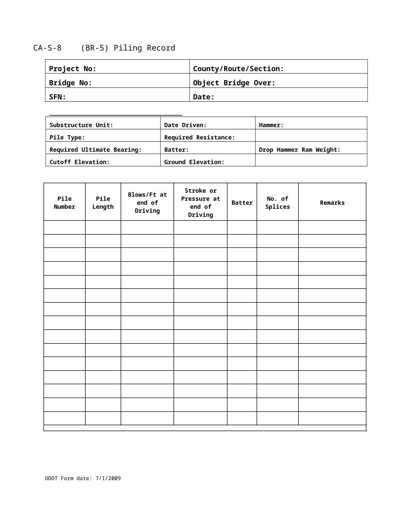
TE-45 Concrete Inspectors Daily Report (back)
ODOT Form date: 7/1/2009

CA-C-1 Concrete Control Test Form
ODOT Form date: 7/1/2009
Project No.: ____________________________ Co./Rt./Sec.: ______________________________
Name: ________________________________ Date: ___________ Truck No.: ______________
Arrival Time: _______________________ Discharge Time: ______________________________
Placement Description: ____________________________________________________________
Placement Location: _______________________________________________________________
Cylinder Sample Numbers: ________________________________________ Class ____ Concrete
Full Pot Weight = (+) ___________________ lbs.
Empty Pot Weight = (-) ___________________ lbs.
Concrete Weight = ___________________ lbs.
Air Pot Factor = ¿ ____________________
Weight of One Cubic Foot (Unit Weight) = ____________________ lbs / ft3
Batch Weight
Fine Aggregate Weight: ________ lbs / _______ yd3 = _________________ lbs
Coarse Aggregate Weight ________ lbs / _______ yd3 = _________________ lbs
Cement Weight ________ lbs / _______ yd3 = _________________ lbs
Water Batch Weight ________ lbs / _______ yd3 = _________________ lbs
Additional Weight ________ lbs / _______ yd3 = _________________ lbs
One Cubic Yard Batch Weight = _________________ lbs
Yield Test Results
Yield=One Cubic Yard Batch WeightUnit Weight of the Sample
=____________________ Cubic Feet
Air = ____ % , Slump = _____ inch , Air Temp. = ____ , Concrete Temp.= _____
CA-C-1 Concrete Control Test Form (back)
ODOT Form date: 7/1/2009
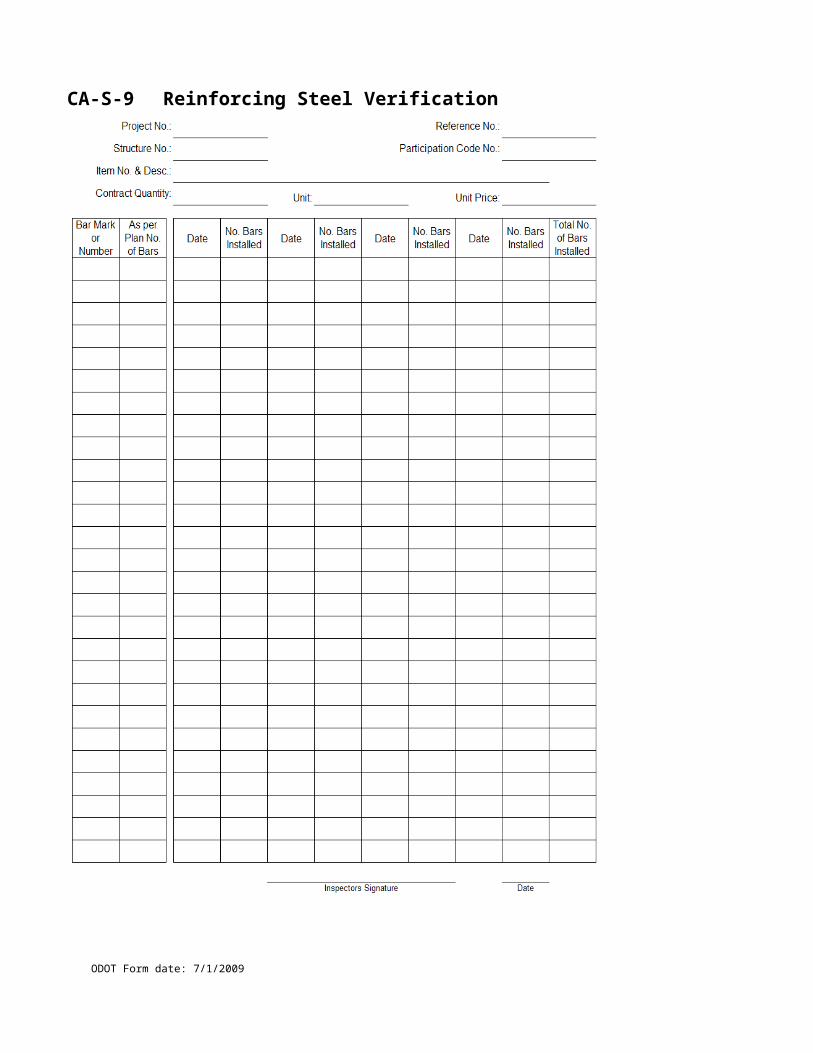
CA-EW-1 Earthwork Quantity Calculations
ODOT Form date: 7/1/2009
CA-EW-1 Earthwork Quantity Calculations (back)
ODOT Form date: 7/1/2009

CA-EW-2 Proof Rolling Documentation
ODOT Form date: 7/1/2009
Project No. Co-Rt-Sec Date
Ref. No. Item No. and Description
Location Wt. of TireTime Elapsed Time Lane Roller Pressure
Start Stop Hours Min. Station to Station Lt/Rt tons psi Remarks
Hours Min. Wt. of Tire
Daily Total C&MS 204.06 Roller Pressure
(round to the nearest 6 minutes, 0.1 hour) silt, clay, and fine sand 35 120granular soil types 50 150
Areas to Correct or InvestigateLane
Station to Station Lt/Rt Elastic or Plastic Movement
Signatures
Inspector Date Contractor Date
Rut Depth Cracking
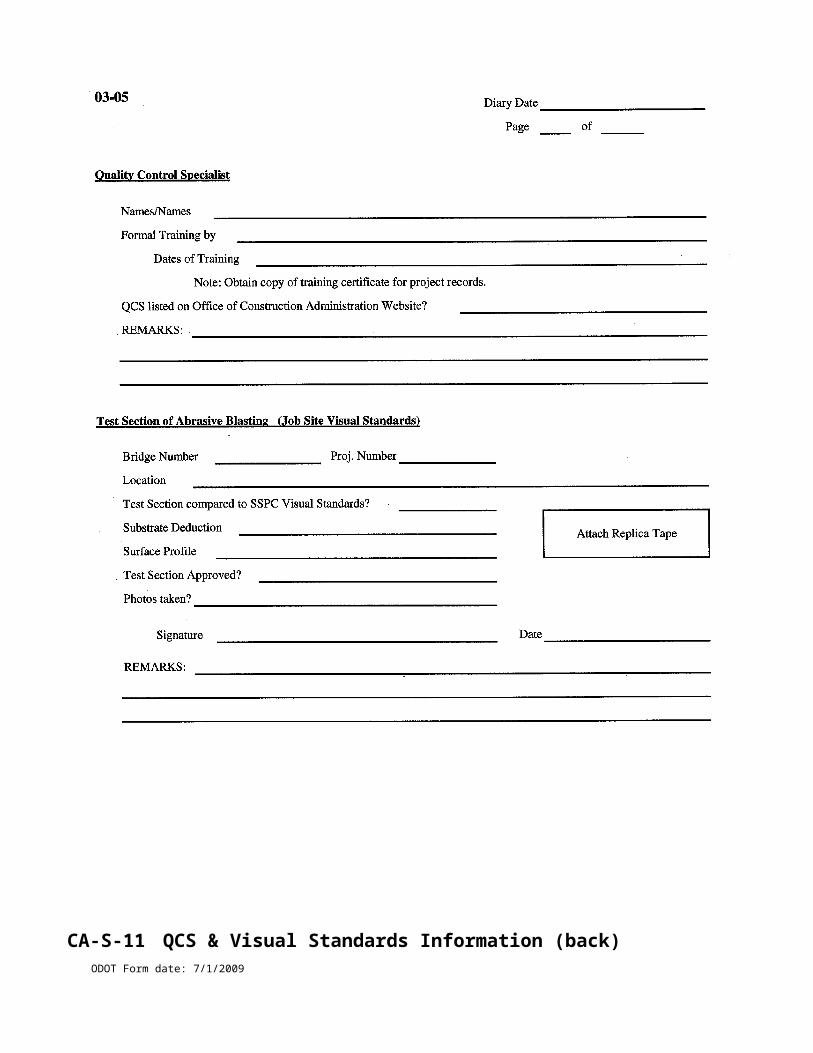
CA-EW-2 Proof Rolling Documentation (back)
ODOT Form date: 7/1/2009
CA-EW-3 Log of Test Pit Investigation
ODOT Form date: 7/1/2009
Project No. Co-Rt-Sec Date
Proof Rolling ResultsLane Rut
Station to Station Lt/Rt Depth Cracking Elastic or Plastic Movement
Test Pit Location
Station Offset Subgrade Elevation
HandDepth Depth Penetrometer Layer Descriptionfrom to ton/ft²
U1 = Material type:
U2 = Layer thickness (ft):
U3 = Soil / rock conditions:
Avg = Comments:
U1 = Material type:
U2 = Layer thickness (ft):
U3 = Soil / rock conditions:
Avg = Comments:
U1 = Material type:
U2 = Layer thickness (ft):
U3 = Soil / rock conditions:
Avg = Comments:
U1 = Material type:
U2 = Layer thickness (ft):
U3 = Soil / rock conditions:
Avg = Comments:
Material Types - clay, silt, sand, gravel, shale, rock (see Construction Inspection MOP 203.02)Soil conditions - wet, dry, organic, roots, water seepage, soup, jello, hard or soft peanut butter
Take photographs of test pit.Draw diagram of test pit andrelevant features on back.
Inspector Date
To edit the spreadsheet in Excelunprotectthen "Unprotect Sheet". There is no password.
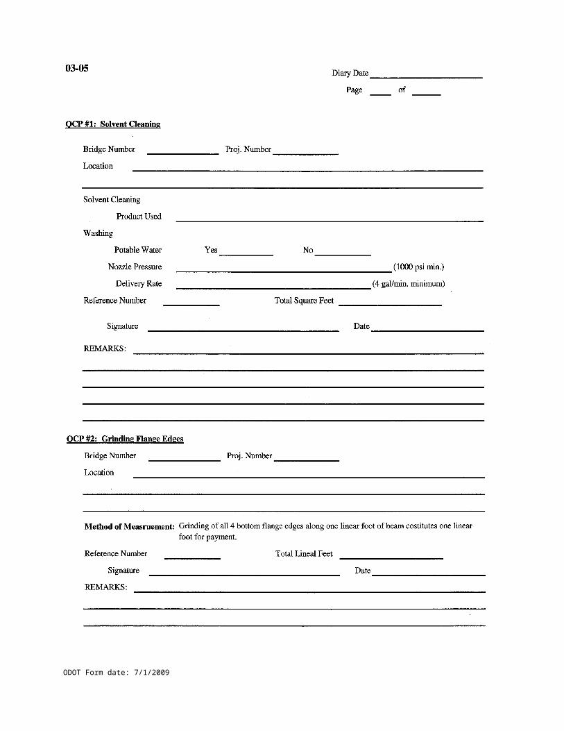
CA-EW-3 Log of Test Pit Investigation (back)
ODOT Form date: 7/1/2009
CA-EW-4 Moisture Density Curve Calculation
ODOT Form date: 7/1/2009
CA-EW-4 Moisture Density Curve Calculation (back)
ODOT Form date: 7/1/2009
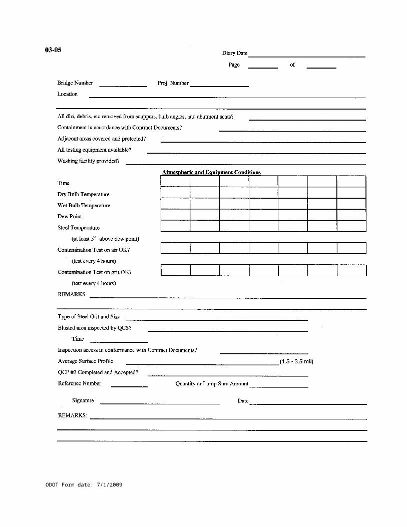
CA-EW-5Nuclear Gauge Compaction Form
ODOT Form date: 7/1/2009

ODOT Form date: 7/1/2009
CA-EW-5 Nuclear Gauge Compaction Form (back)
ODOT Form date: 7/1/2009
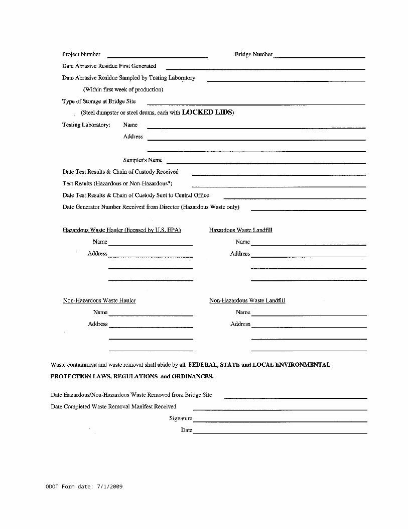
CA-EW-6 Nuclear Gauge Compaction with Aggregate Correction
ODOT Form date: 7/1/2009
CA-EW-6 Nuclear Gauge Compaction with Aggregate Correction (back)
ODOT Form date: 7/1/2009
Typical Moisture Density Curves - Set C - May, 1949
ODOT Form date: 7/1/2009
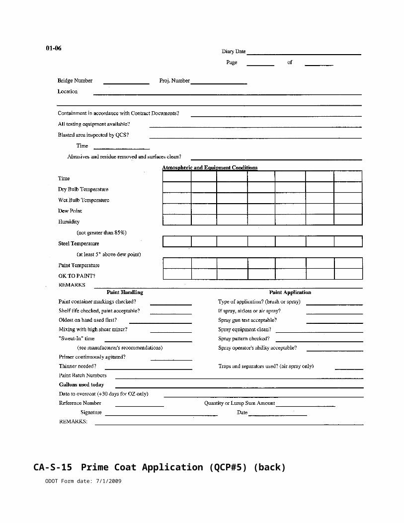
Zero Air Voids Curve
ODOT Form date: 7/1/2009
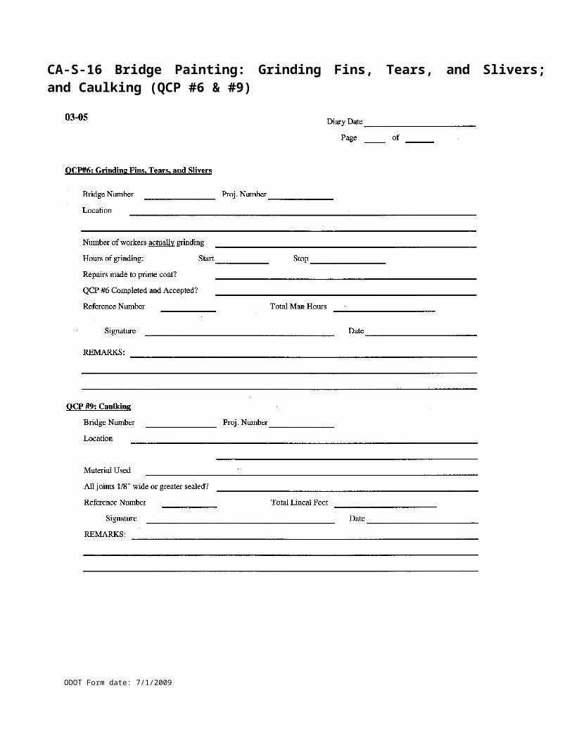
CA-EW-8 Authorization of Undercuts
ODOT Form date: 7/1/2009
Project No. Co-Rt-Sec Date
Description
Instructions1. All undercuts to be paid for shall be performed as directed by the Engineer and in accordance with the MOP.2. Measurements may be made by cross-sections or average length, width and depth, whichever is more appropriate.3. Furnish material removed, backfill, measurement type and location information.4. Submit origional copy to District Construction Office immediately. Furnish copy to Contractor if requested.
Material Removed BackfillSuitable and used for fill Material from right-of-waySuitable and wasted Earth from borrowUnsuitable Granular from borrow
Measurement Type LocationCross-sections per attached notes Right or Left of centerline
Measurements per drawing Elevation bottom of undercut
Location Average Average Average Quantity AllowedRef. Item Lane Length Width Depth for PaymentNo. No. Station to Station Lt/Rt ft ft ft yd³
to
to
to
to
to
Drawings or Calculations
Signatures
Inspector performing measurements Date Contractor's Superintendent or Foreman Date
Inspector performing calculations Date Project Engineer or Supervisor Date
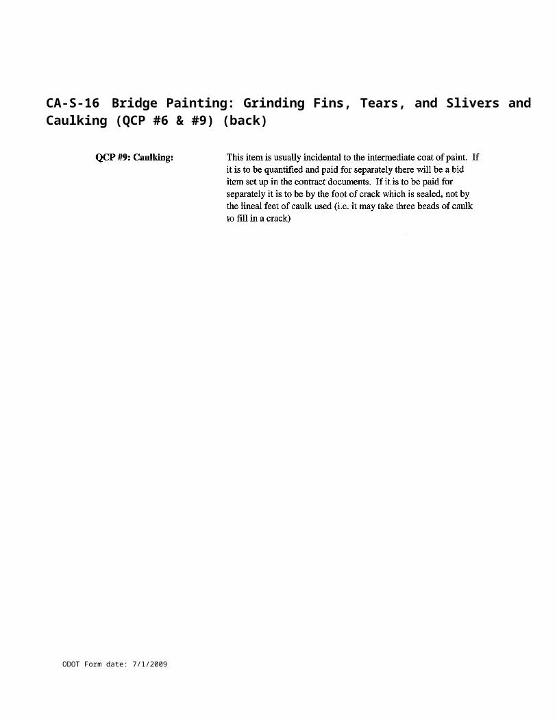
CA-EW-8 Authorization of Undercuts (back)
ODOT Form date: 7/1/2009
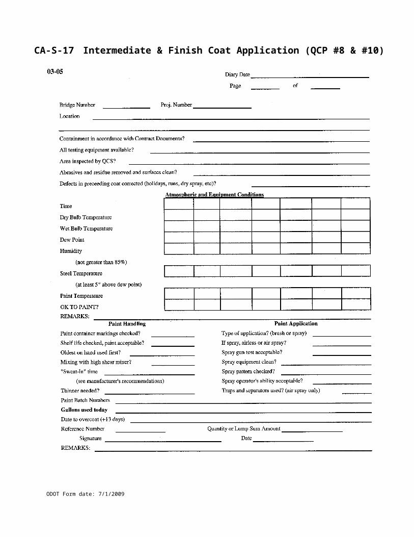
CA-EW-9 Rock Blasting Inspection Form
Project No. Co-Rt-Sec Date
Blast No. Station
Blast Type: Test Section Production Presplit Trench
Number of holes
Hole diameter D inches
Bench height L ft
Burden B ft
Spacing S ft
Blast hole depth H ft
Stemming T ft
Powder column length PC ft
Subdrilling J ft
? 1.0
0.7 B = ? T
Nearest Critical Structure Distance ft
Comments
Inspector Date
B
H
J
T
PC
L
S
D
BL
ODOT Form date: 7/1/2009

CA-EW-9 Rock Blasting Inspection Form (back)
ODOT Form date: 7/1/2009
CA-EW-10 Rock Blasting Drilling LogProject No. Co-Rt-Sec Date
Drilling Company Driller in Charge
Burden ft Spacing ft Bench Height ft
Hole Depth Subdrill Angle DiameterNo. ft ft degrees inch Comments (voids, seams, mud, lack of cuttings, etc.)
Driller Date
ODOT Form date: 7/1/2009
CA-EW-10 Rock Blasting Drilling Log (back)
ODOT Form date: 7/1/2009
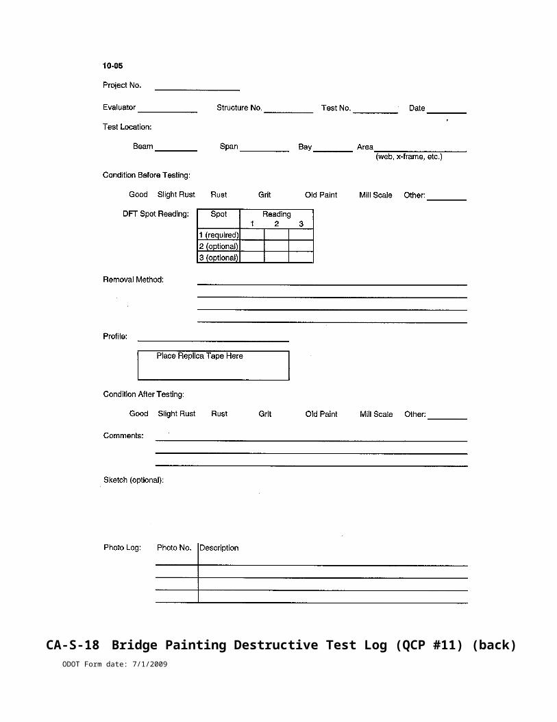
CA-EW-11 Blast Site Security Plan
Project No. Location Date
Prime Contractor
Blasting Contractor
Blasting Times and Frequency
Blast Signal Type dB
Blasting Signal Procedures
Site Security Procedures
Blaster(s) in charge
Name Signature Date
Name Signature Date
Name Signature Date
Contractor's Superintendent
Name Signature Date
1. Project Number as given by Ohio DOT
2. Location of project (example: US 52 Bypass Portsmouth, OH)
3. Prime Contractor's name
4. Blasting Contractor's name if different from Prime Contractor
5. Blasting Times and Frequency (example: Monday
6. Type of Blast Signal (example: Siren will be located at ODOT trailer mounted on 30 foot pole)
7. Blasting Signal Procedures: Give complete description of what the blasting signals are. Example: A siren will be sounded for 60 seconds 5 minutes prior to blasting followed by 3 short blasts of the siren 30 seconds prior to blasting.
8. Site Security Procedures: Give a complete detailed description of how the blast site is to be defined and cleared prior to blasting. Give complete description of who is responsible for blocking and maintaining access to blast site and what means of communication is being used to monitor and maintain access to the blast site. List responsible parties for each step.
9. List each blaster in charge on the project and signature showing receipt and acknowledgement of the Blast Site Security Plan.
10. Name and signature of prime contractor's superintendent acknowledging review and approval of plan.
ODOT Form date: 7/1/2009
CA-EW-11 Blast Site Security Plan (back)
1. Project Number as given by Ohio DOT
2. Location of project (example: US 52 Bypass Portsmouth, OH)
3. Prime Contractor's name
4. Blasting Contractor's name if dif ferent f rom Prime Contractor
5. Blasting Times and Frequency (example: Monday – Friday, 10 AM - 4 PM)
6. Type of Blast Signal (example: Siren will be located at ODOT trailer mounted on 30 foot pole)
7. Blasting Signal Procedures: Give complete description of what the blasting signals are. Example: A siren will be sounded for 60 seconds 5 minutes prior to blasting followed by 3 short blasts of the siren 30 seconds prior to blasting.
8. Site Security Procedures: Give a complete detailed description of how the blast site is to be def ined and cleared prior to blasting. Give complete description of who is responsible for blocking and maintaining access to blast site and what means of communication is being used to monitor and maintain access to the blast site. List responsible parties for each step.
9. List each blaster in charge on the project and signature showing receipt and acknowledgement of the Blast Site Security Plan.
10. Name and signature of prime contractor's superintendent acknowledging review and approval of plan.
ODOT Form date: 7/1/2009
CA-EW-12 Daily Earthwork Inspection Form
Project No. Co-Rt-Sec Date
Ref. No. Item No. and Description
Location of Excavation or Borrow Pit
Location of Embankment or Waste Area
Equipment (number and type)
Dozers Backhoes Vibratory Rollers
Graders Draglines Tamping Foot Rollers
Scrapers Clam Buckets Sheepsfoot Rollers
Dozer/Scrapers Water Trucks Pad Foot Rollers
Dump TrucksOther Other
ExcavatorsOther Other
Type of soil (sand, clay, silt, shale, random, etc.)
Was water added to fill today? if yes, list station limits to
Was soil aerated (dried) today? if yes, list station limits to
Measured loose lift thickness inches Was fill rolled full width?
How was thickness measured?
Location of compaction tests and results:
Today's load count Est. CY/load Average round trip time
Estimated quantity calculations
Instructions given today (from whom, to whom, and to do what):
Comments
Provide a copy of this formto the contractor. Inspector Date
To edit the spreadsheet in Excelunprotectthen "Unprotect Sheet". There is no password.
Yes
Yes No
No
Yes No
ODOT Form date: 7/1/2009
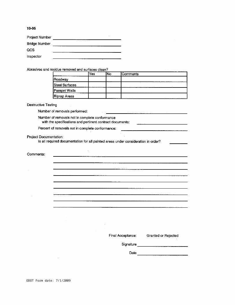
CA-EW-12 Daily Earthwork Inspection Form (back)
ODOT Form date: 7/1/2009
CA-EC-1 Weekly and Rain Event Checklist
ODOT Form date: 7/1/2009
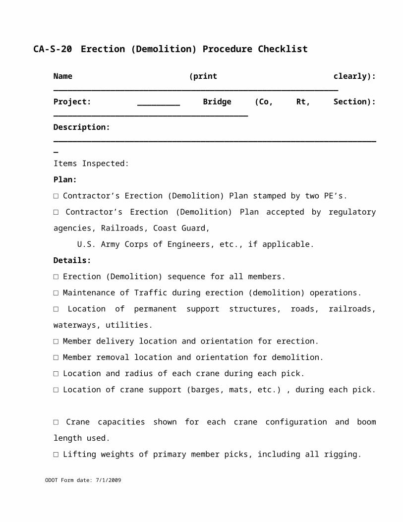
CA-EC-1 Weekly and Rain Event Checklist (back)
ODOT Form date: 7/1/2009
CA-EC-2 Seeding Calculations
ODOT Form date: 7/1/2009
Project No: County/Route/Section:
Ref. No: Item & Description:
Left Right
Station Width Sum Dist Sq. Yd. Station Width Sum Dist Sq. Yd.
---- ---- ---- ---- ---- ----
---- ----
---- ---- ---- ---- ---- ----
---- ----
---- ---- ---- ---- ---- ----
---- ----
---- ---- ---- ---- ---- ----
---- ----
---- ---- ---- ---- ---- ----
---- ----
---- ---- ---- ---- ---- ----
---- ----
---- ---- ---- ---- ---- ----
---- ----
---- ---- ---- ---- ---- ----
---- ----
---- ---- ---- ---- ---- ----
---- ----
---- ---- ---- ---- ---- ----
Total Total
Remarks: _______________________________________________________________________
________________________________________________________________________________
Test conducted by:
Inspected By: Date:
Checked By: Date:
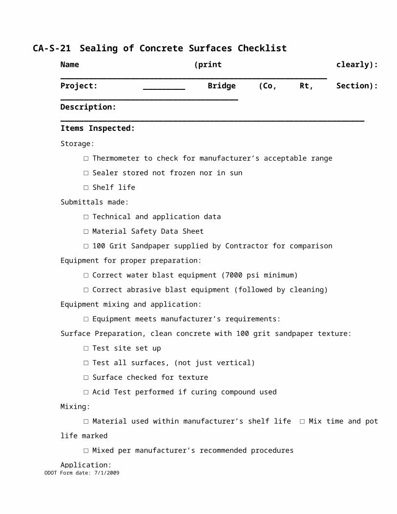
CA-EC-2 Seeding Calculations (back)
ODOT Form date: 7/1/2009
CA-FP-1 Warranty Asphalt Checklist
ODOT Form date: 7/1/2009
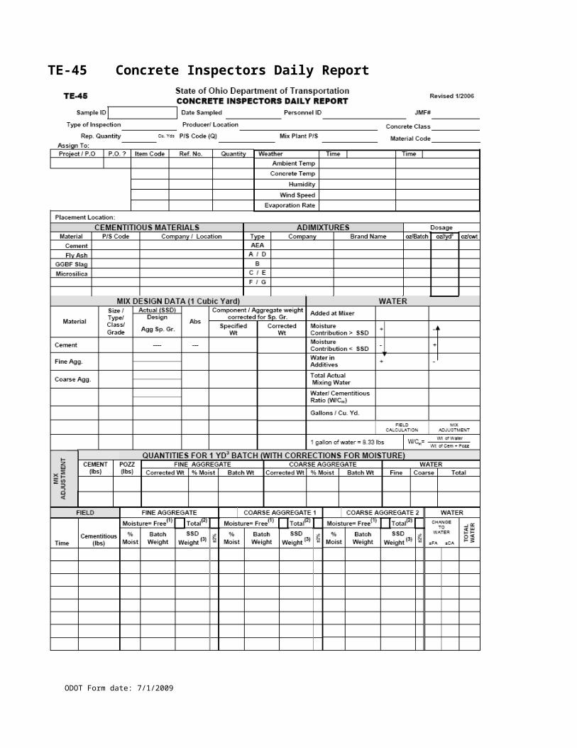
CA-FP-1 Warranty Asphalt Checklist (back)
ODOT Form date: 7/1/2009
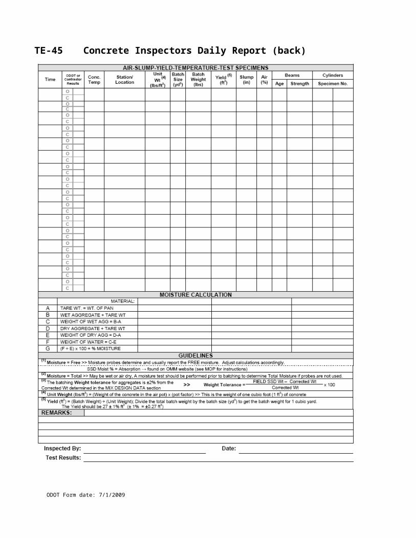
CA-FP-2 Random Selection of Asphalt Field Samples (448, 403)
ODOT Form date: 7/1/2009
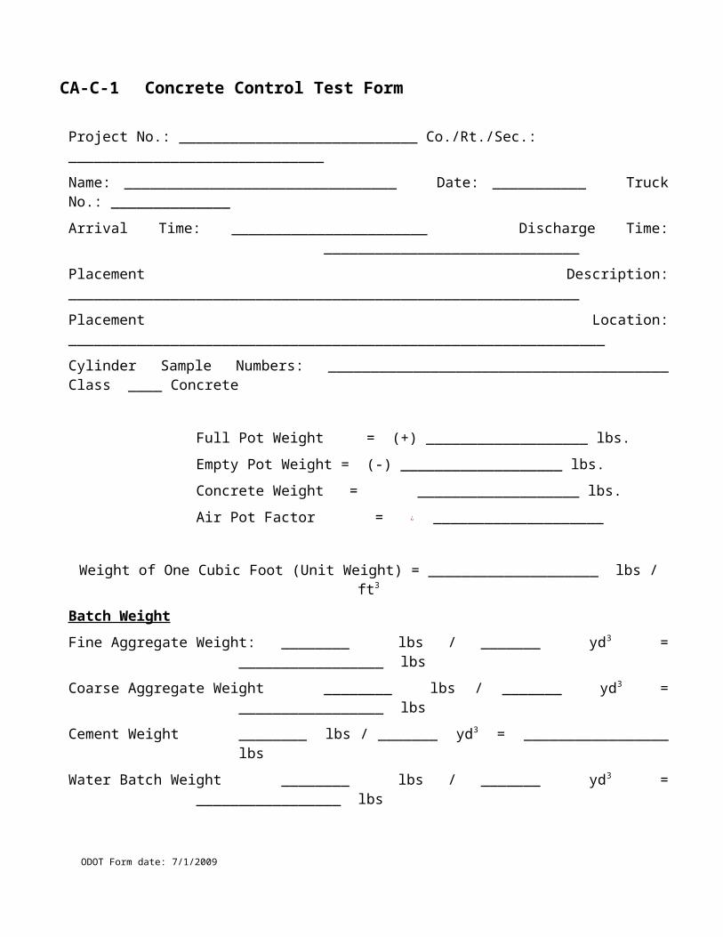
CA-FP-2 Random Selection of Asphalt Field Samples (448, 403) (back)
ODOT Form date: 7/1/2009
CA-FP-3 Summary of Asphalt Concrete Quantities
ODOT Form date: 7/1/2009
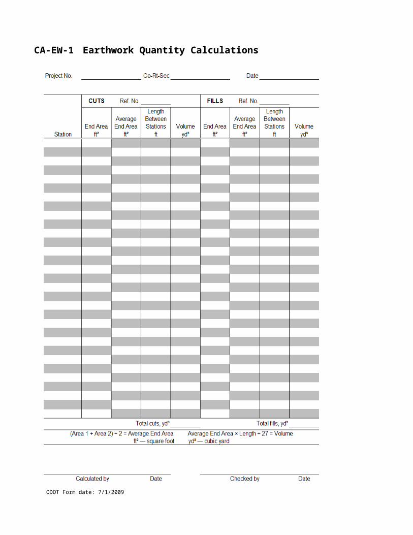
CA-FP-3 Summary of Asphalt Concrete Quantities (back)
ODOT Form date: 7/1/2009

CA-FP-4 Asphalt Concrete inspection
ODOT Form date: 7/1/2009
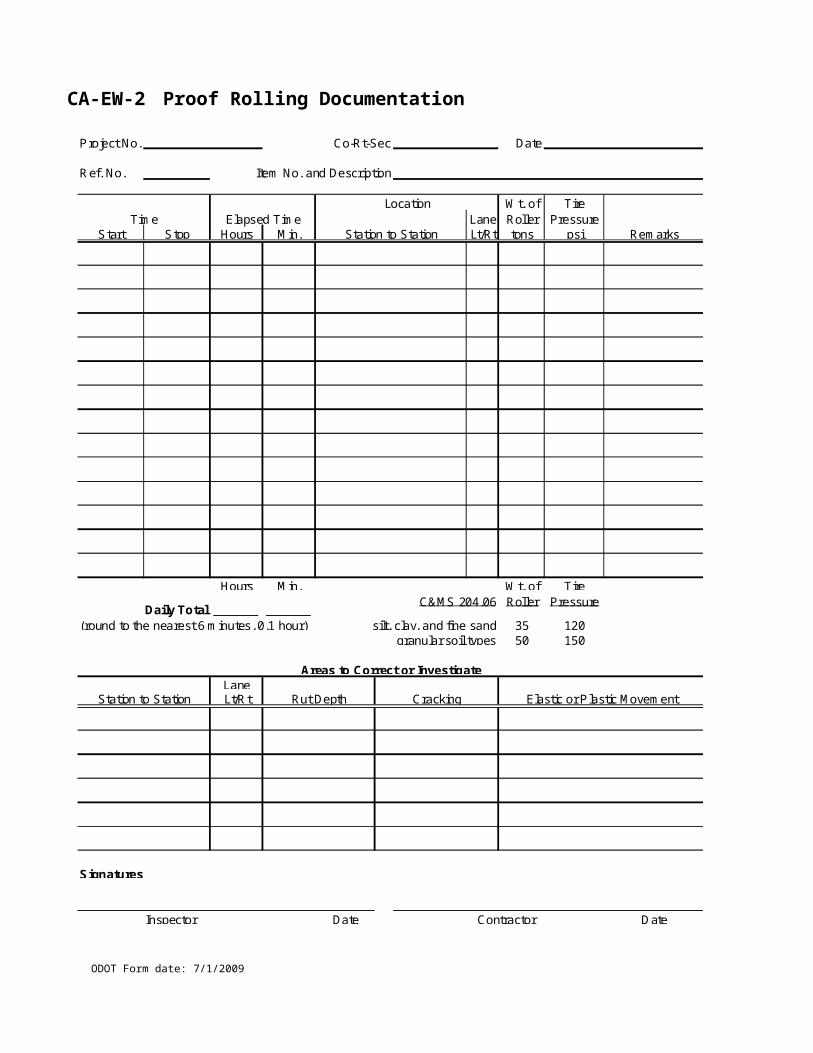
CA-FP-4Asphalt Concrete inspection (back)
ODOT Form date: 7/1/2009
ODOT Form date: 7/1/2009
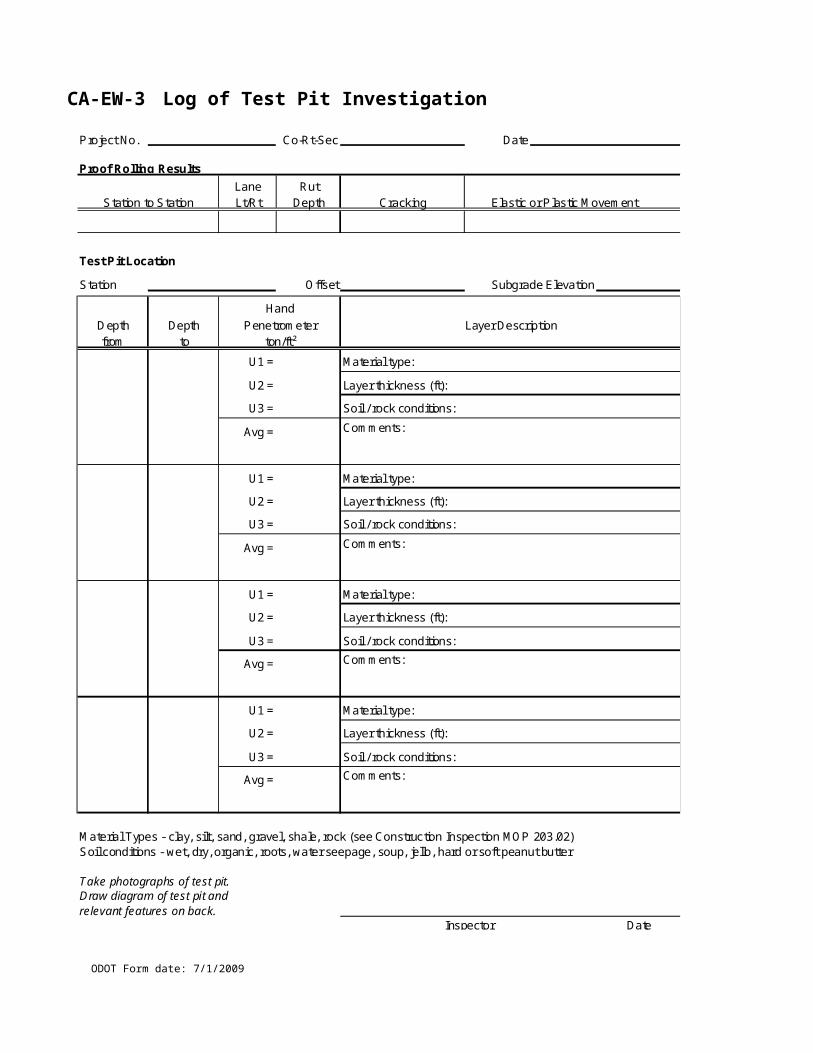
CA-FP-5 Roller Capacity and Placement Rate
1) Check rollers used; fill in the total weight and compare to requirements in 401.13-2 and -3. Contractor is to provide weights.2) Calculate the total roller train capacity in (square yards per hour) and compare it the calculated placement rate. 3) Check compression rolls for steel wheel rollers and compare to requirements in 401.13-2.4) This procedure must be used for asphalt concrete courses that do not have a density specification.
Compression Roll Check for Steel Wheel Rollers
(Inches)
(Ton/CY)
Date P.E./P.S. Signature Date
Date
County, Route, Section
Ref #
Project #
Contractor Item #
Plan Pg
Description
Total Roller Capacity
Location Bubble #
Roller Type Weight** Roller Capacity # Rollers # Drums Width*(in.) (SY/HR)(Check all that apply) (Lbs) (SY/HR)
0.0Tandem 700
0.0Three-Wheeled 700
0.0Trench15 SY/HR per Inch
Width*
0.0Pneumatic Tire, Type 1 1000
0.0Pneumatic Tire, Type 2 700
0.0Vibratory Roller, vibration mode15 SY/HR per Inch
Width*
0.0Vibratory Roller, static mode 3 SY/HR per Inch
Width*
0.0 (SY/HR)
0.0 (Ton/HR)
Thickness of Pavement Mat
Material Conversion Factor
Maximum Roller Capacity
Maximum Pavement Placement Rate
* Width = width of the roller drum. ** Weight - Check for compliance with 401.13-2 and -3. Contractor to provide roller weight.
Inspector's Signature
Remarks
Tandem
(Check all that apply) (Lbs) (IN)Weight Width
Vibratory Roller, static mode
Trench
Three-Wheeled
Compression Roll*(Lbs/IN)
* Check for compliance with 401.13-2
Roller Type
ODOT Form date: 7/1/2009

CA-FP-5 Roller Capacity and Placement Rate (back)
ODOT Form date: 7/1/2009
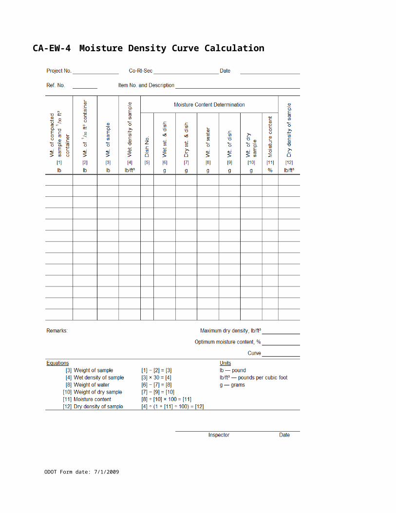
CA-FP-6 Calculation of Liquid Asphalt Materials
12
3
45
6
Item #
Date
Project # County, Route, Section
Description
Contractor
Distributor No. Distributor Capacity
Bubble #
Ref #
Plan Pg
(GAL)
Location
Name and Location of Plant
Material Code JMF
Supplier
Gross Wt (LBS)
Tare Wt (LBS)
Date
Net Wt (LBS)
Temp Factor
Specific Gravity
( Gross Wt - Tare Wt )
… ( # 1 - # 2 )
( Net Wt / (Temp Factor x Specific Gravity )
… ( # 3 / ( # 4 x # 5 )
Volume (GALS)
Inspector's Signature
ODOT Form date: 7/1/2009

CA-FP-6 Calculation of Liquid Asphalt Materials (back)
Notes:This formula calculates volume at the specified pay temperature (109.01) for the asphalt material. If the actual temperature, as measured in the tank truck or distributor, differs from the specified pay temperature, the pay volume must be adjusted as per Supplement 1060.
Values for Temperature Factor, ""K"", and Coefficient of Expansion are included in ODOT Supplement 1060, Table A. Table B provides Pay Temperature and an index of formulas to be used for calculating volume based on actual measured temperature."
ODOT Form date: 7/1/2009
TE-217 Bituminous Concrete Density Determination - 446 Cores
ODOT Form date: 7/1/2009
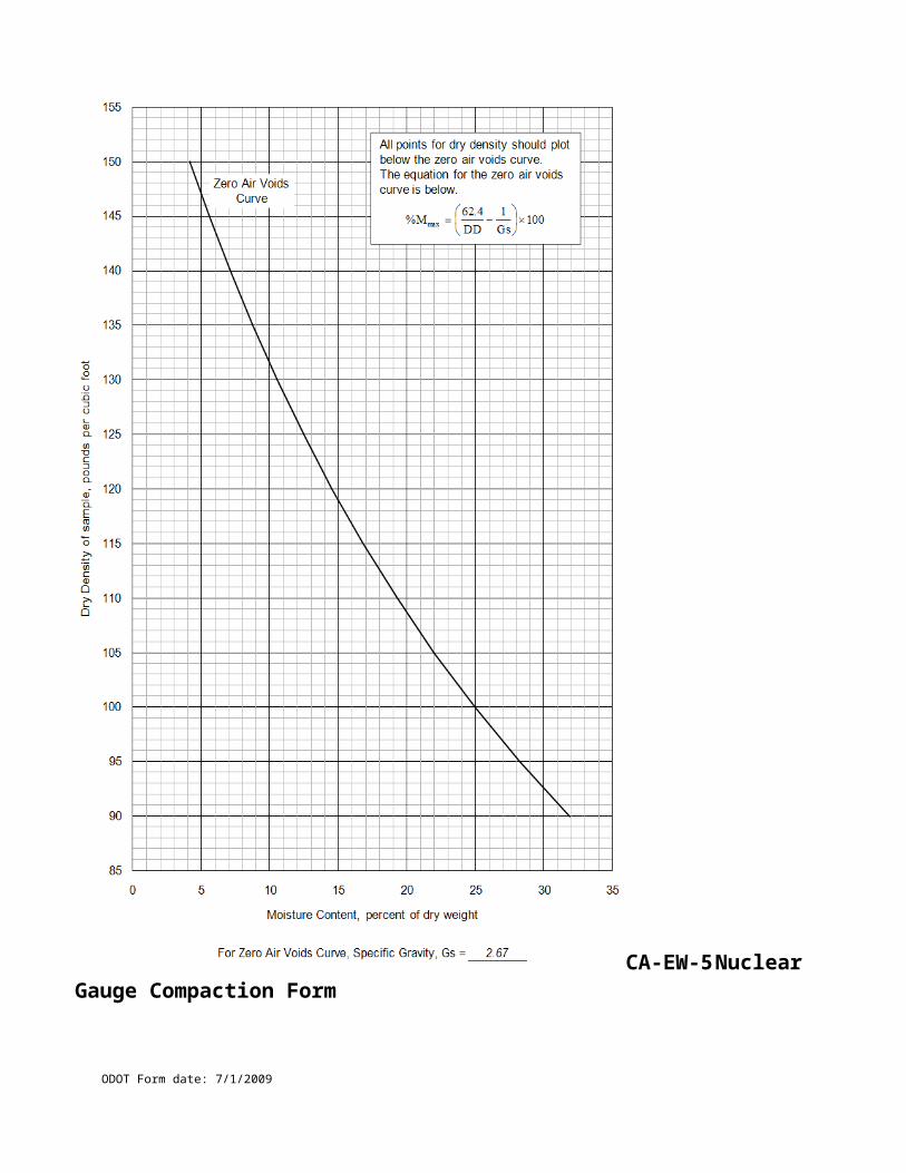
TE-217 Bituminous Concrete Density Determination - 446 Cores
ODOT Form date: 7/1/2009
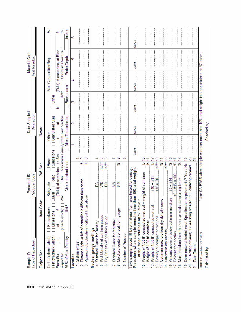
TE-217 Bituminous Concrete Density Determination - 446 Form Instructions
ODOT Form date: 7/1/2009

TE-217 Bituminous Concrete Density Determination - 446 Cores Instructions
ODOT Form date: 7/1/2009
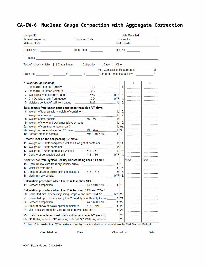
TE-217 Bituminous Concrete Density Determination - 446 Random Number Table
ODOT Form date: 7/1/2009

TE-217 Bituminous Concrete Density Determination – (Blank)
ODOT Form date: 7/1/2009
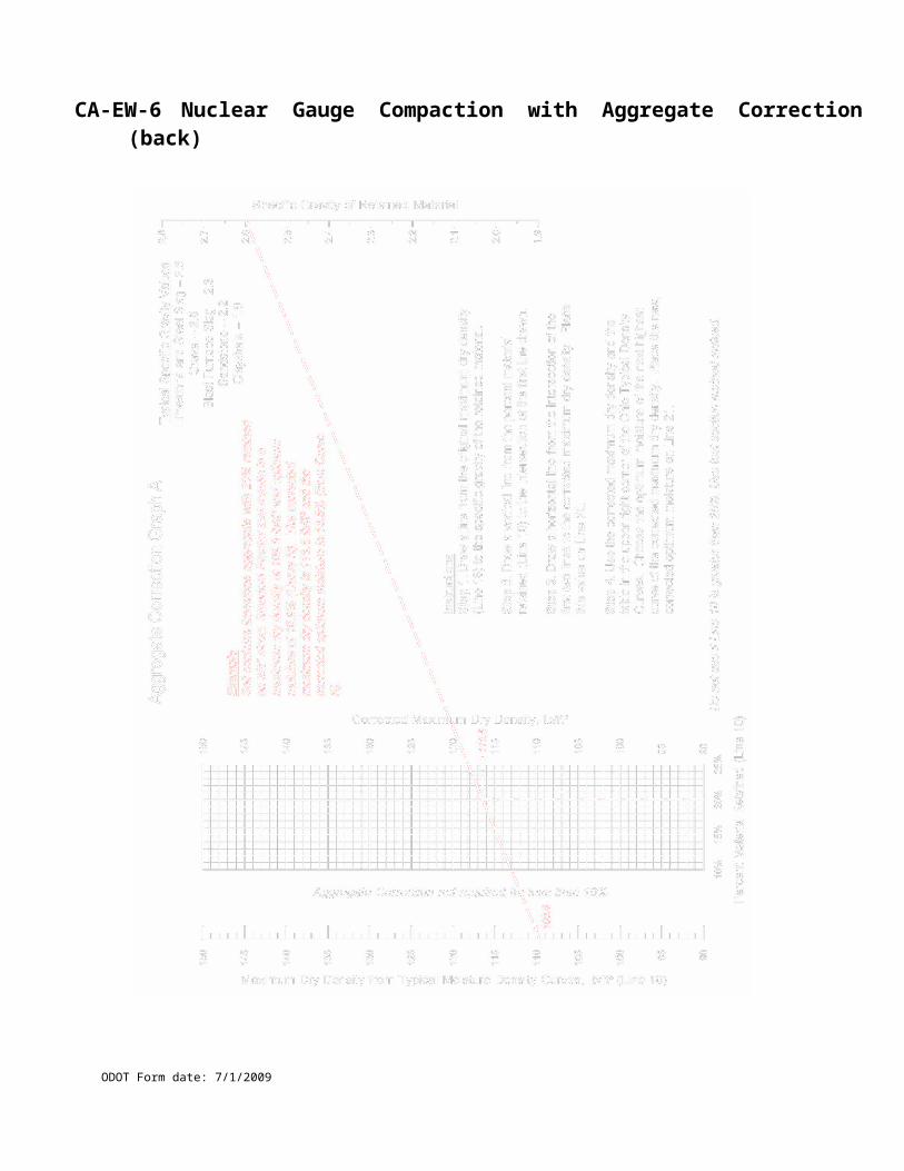
CA-P-1 Pipe Construction Inspection Form - 1/2
ODOT Form date: 7/1/2009
Project # _____________________ County, Route & Section _________________________________________
Sample ID _____________________ Personnel ID _____________________ Date Sampled _____________________
Item # _____________________ Ref. # Producer Code Contractor _____________________
Description ____________________________________________________________________________________
Location _________________ Balloon Ref. # __________Plan Page __________ Pipe Material (RCP, Metal, HDPE, Other)
Type of Pipe (circle one) A B C D E F Pipe Markings ____________Provide a 2 to 1 slope from top of pipe in a cut to the top of excavation
Provide a 2 to 1 slope from spring-line of pipe in a fill to the top of excavation W = Width of trench at Top of Pipe. Refer to Spec. 603.03
W = Width of trench at Top of Pipe. ______ Refer to Spec. 603.03
B = Thickness of bedding under pipe. _______________________
T = Outside diameter of pipe to trench wall. _____________________
S = Depth of bedding. ____________
OD = Outside diameter of pipe. ____________________________
* Type 2 is Shown See Specification For Type 1,3,4
For Type 2 Bedding Plastic: B= 6"(150 mm) S= B + 30% OD
For Type 2 Bedding Non Plastic: B= 3"(75 mm) S= B + 30% OD
TRENCH & BEDDING CHECKS (ACTUAL FIELD MEASUREMENTS)Check Stations & Location T W B S O.D. Initial Date
* Recommended checks every 50 feet, with a minimum of two checks per run. Check locations may be related to starting point such as outlet end, catch basin, C/L station, etc.
Field Measurements
Lf. (meter)
Plan Pay Length Lf.
(meter)
Grade Check
Method
BackfillCompaction
Form#Initials &
DateCompaction Method Tamp,
Flood, etc.
Type: Soil or Structural
Backfill 1,2 or 3
Lift Depth
Type of Joints (603.06) _____________________ Joints Installed Satisfactorily? Yes No
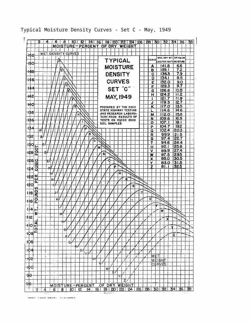
CA-P-1 Pipe Construction Inspection Form 2/2
ODOT Form date: 7/1/2009
Balloon Ref. # (s):______________________ Plan Page (s):___________________________________
Station to Station: _____________________________________________________________________
Plan Quantity: __________________________ LF (meters)
Remarks: __________________________________________________________________________
Daily Total Field Measured: ________________ LF (meters) *
Remarks: ___________________________________________________________________________
Daily Total Authorized Pay: ________________ LF (meter)**:_________________________________
* Explain field measurements and authorized pay. Pay in accordance with 603.12 Method of Measurement? a) Structure or pipe end location moved or least cost to State when accommodating full sections.b) Measured to C/L of structure when inside structure dimension is over 6 linear feet (2 meters) in direction of flow or only one structure on the run of pipe.c) You must account to "Lab" for pipe length due to creep & measurements to C/L of structures.
** Round all Items Reference to nearest 0.1 foot (0.03 meter).
Remarks: Record problems, soft foundations, under cuts, rock, instructions, utilities encountered, etc. Describe and note location of existing conduits encountered, whether connected, plugged and abandoned, reconnected, etc.
____________________________________________________________________________________________________________________________________________________________________________________________________________________________________________________________________________________________________________________________________________________________________________________________________________________________________
____________________________________________________________________________________
Sketch area:
CA-P-2 Underdrain Construction Inspection Form 1/2
ODOT Form date: 7/1/2009
Project # __________________ County, Route & Section __________________________________________________
Sample ID_________ Personnel ID__________________ Date Sampled______________________________________
Item # _________ Ref. #_________ Producer Code_________ Contractor_____________________________________
Description ______________________________________________________________________________________
Location _________Balloon Ref. # _________Plan Page_________ Pipe Material (RCP, Metal, HDPE, Other)
Underdrain Markings_______ Filter Fabric Required _______Underdrain Joint Type_________ (coupler, bell & Spigot )
W = Width of trench.__________
D= Depth of Trench ____________
D T =Outside pipe to trench wall. _____________
ID = Inside diameter of pipe. ___________
TRENCH & BACKFILL CHECKS (ACTUAL FIELD MEASUREMENTS)Station to StationRight, Left Side
Every 50 feet (20m)
T W I.D. BackfillMaterial8,9,89’s
OutletStation
How OutletCatch Basin
Slope
Initial Date DatePav’t
Placed
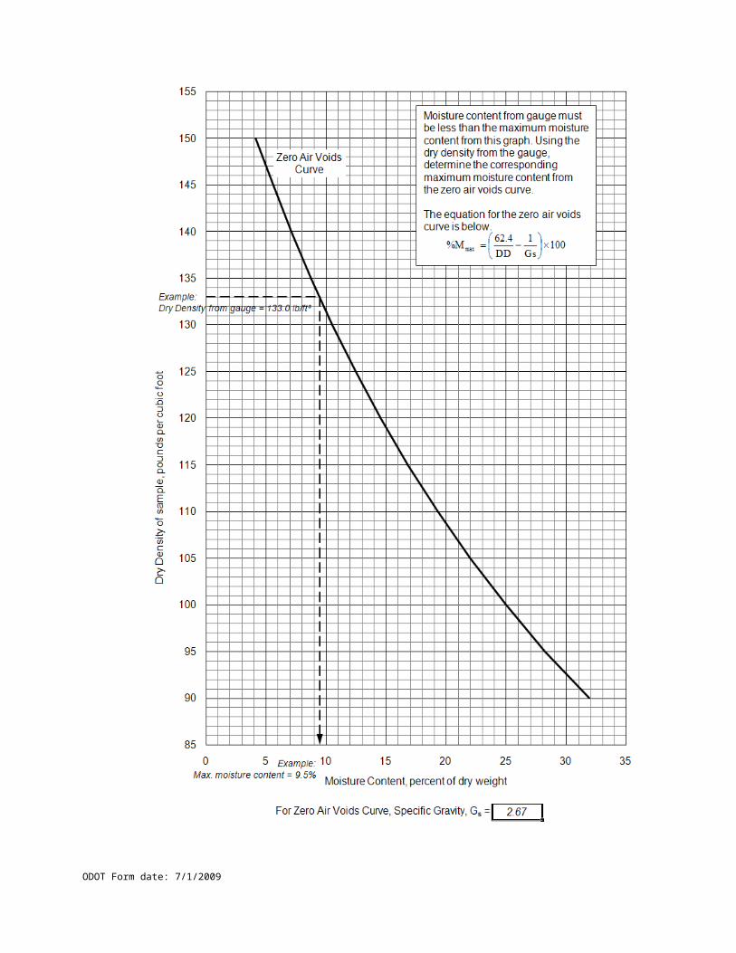
CA-P-2 Underdrain Construction Inspection Form 2/2
ODOT Form date: 7/1/2009
Balloon Ref. # (s):_____________________ Plan Page (s):____________________________________
Station to Station: _____________________________________________________________________
Plan Quantity: __________________________ LF (meters)
Remarks:
____________________________________________________________________________________
____
Daily Total Field Measured: ________________ LF (meters) *
Remarks:
____________________________________________________________________________________
___
Daily Total Authorized Pay: ________________ LF (meter)**:
____________________________________________
* Explain field measurements and authorized pay. Pay in accordance with 603.12 Method of Measurement? a) Structure or pipe end location moved or least cost to State when accommodating full sections.b) Measured to C/L of structure when inside structure dimension is over 6 linear feet (2 meters) in direction of flow or only one structure on the run of pipe.c) You must account to "Lab" for pipe length due to creep & measurements to C/L of structures.
** Round all Items Reference to nearest 0.1 foot (0.03 meter).
Remarks: Record problems, soft foundations, under cuts, rock, instructions, utilities encountered, etc. Describe and note location of existing conduits encountered, whether connected, plugged and abandoned, reconnected, etc.
________________________________________________________________________________________________________________________________________________________________________
____________________________________________________________________________________
Sketch area:
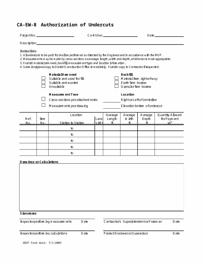
CA-P-3 Drainage Structure Inspection Form 1/2
ODOT Form date: 7/1/2009
Project # _____________________ County, Route & Section
Sample ID Personnel ID Date Sampled
Item # Ref. # Producer Code Contractor
Description
Location _________________ Balloon Ref. # ____Plan Page ____ Material (Precast, Brick-Block, Other)
Temperature _________ Structure Temperature ______ Mortar Temperature ______________
Type of Pipe being placed in structure (circle all that apply) A B C D E F , Structure Markings ______
Lifting Devices are to remain in place. Manhole top type furnished _________________________
W = Width of trench at Top of the Structure.___________B = Thickness of bedding under Structure. ___________T = Structure to trench wall thickness ___________
Type of Bedding Material Furnished _______________Type of Backfill material furnished _______________
Type of Structure (Catch Basin, Inlet, Manhole, 604.02) ________ Type of Joint Material being used (604.06) ________
Pipe OD
Structure Opening Dia.
BackfillCompaction Method
Tamp, Flood, etc.
Type: Soil or
Structural Backfill 1, 2, 3
Lift
Depth
Compaction
Form
Initials
And Date

CA-P-3 Drainage Structure Inspection Form 2/2
ODOT Form date: 7/1/2009
Circle the Application: 1 Proposed Structure, 2 Reconstruction Structure, 3 Adjustment to Grade
Balloon Ref. # ___________ Plan Page ________ Plan Station __________ Offset ___________ Elevation ____________
Structure Top Field Station _______________ Field Offset___________________ Field Elevation____________________
Manhole Plan Base Station _____________________ Offset _____________________ Elevation ____________________
Manhole Field Base Station _________________ Field Offset__________________ Field Elevation__________________
Reconstruction Structure removal depth________ Outlet Pipe Elevation __________ Field Outlet Pipe Elevation________
Is the Sump Finished Per the Standard Drawing: YES __ NO__ Explain: _______________________________________
Is the Consults Finished Per the Standard Drawing: YES __ NO__ Explain: _____________________________________
Authorized Pay: YES _______NO______ Reference Number____________________________
Explain field measurements and authorized pay. Pay in accordance with 604.08 Method of Measurement
Remarks: Record problems, soft foundations, under cuts, rock, instructions, utilities encountered, etc. Describe and note location of existing conduits encountered, whether connected, plugged and abandoned, reconnected, etc. Provide locations and size of any laterals that are not part of a 603 pay Item in a sketch.
____________________________________________________________________________________
Sketch area:
__________________________________________________________________________________________
Inspector’s Signature Date P.E./P.S. Signature

CA-D-1A Field Calculation and Measurement
ODOT Form date: 7/1/2009
Project No: County/Route/Section:
Ref. No: Item & Description:
1Station Location Plan
Sheet
Plan
Ref.
Plan
Quantity
Field
Quantity UnitFrom To Side
Describe Location
1Calculation/Sketch/Additional Remarks:
Special Notes:
Inspected By: Date:
Checked By: Date:
CA-D-1A Field Calculation and Measurement (back)
ODOT Form date: 7/1/2009
CA-D-1B Field Calculation and Measurement
ODOT Form date: 7/1/2009
Project No: County/Route/Section:
Ref. No: Item & Description:
1Station Location Plan
Sheet
Plan
Ref.
Plan
Quantity
Field
Quantity UnitFrom To Side
Describe Location
1Calculation/Sketch/Additional Remarks:
Special Notes:
Prepared By: Date:
Checked By: Date:
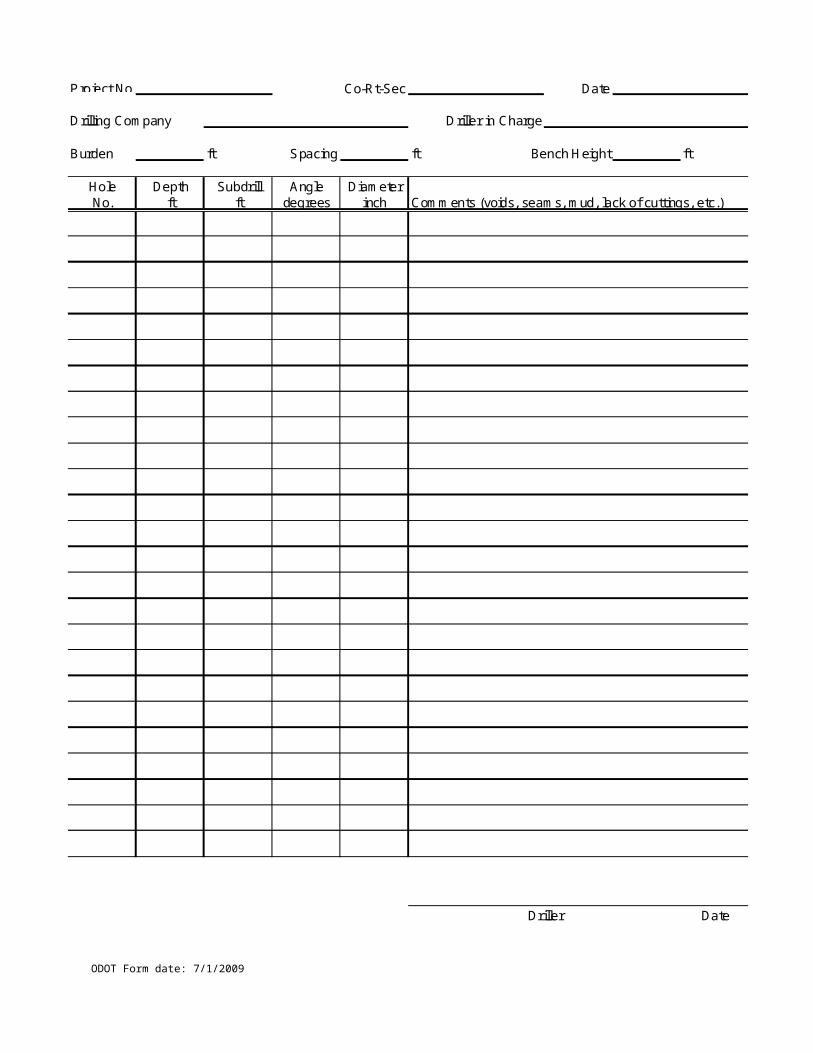
CA-D-1B Field Calculation and Measurement (back)
ODOT Form date: 7/1/2009
CA-D-2 Field Calculation and Measurement
ODOT Form date: 7/1/2009
Project No: County/Route/Section:
1Location
Ref. #: Ref. #: Ref. #: Ref. #:
Item: Item: Item: Item:
Unit: Unit: Unit: Unit:
Date Station or Plan Page L/R
Plan
Quantity
Measured
Quantity
Plan
Quantity
Measured
Quantity
Plan
Quantity
Measured
Quantity
Plan
Quantity
Measured
Quantity
TOTALS
Special Notes:
Inspected By: Date:
Checked By: Date:
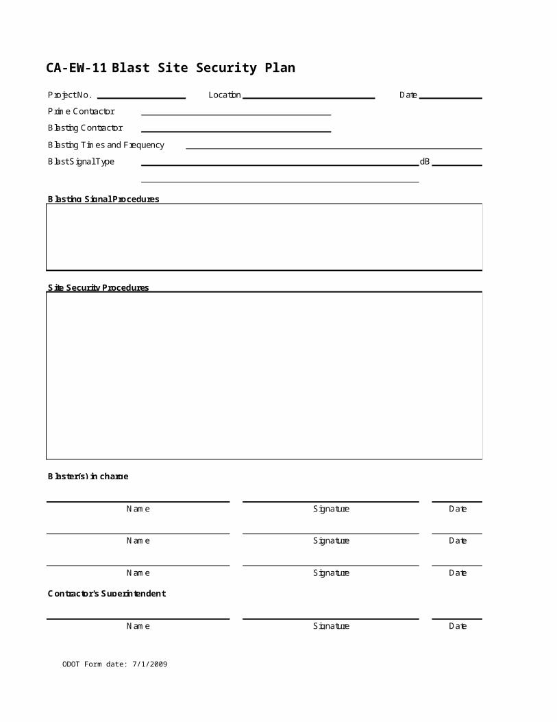
CA-D-2 Field Calculation and Measurement (back)
ODOT Form date: 7/1/2009
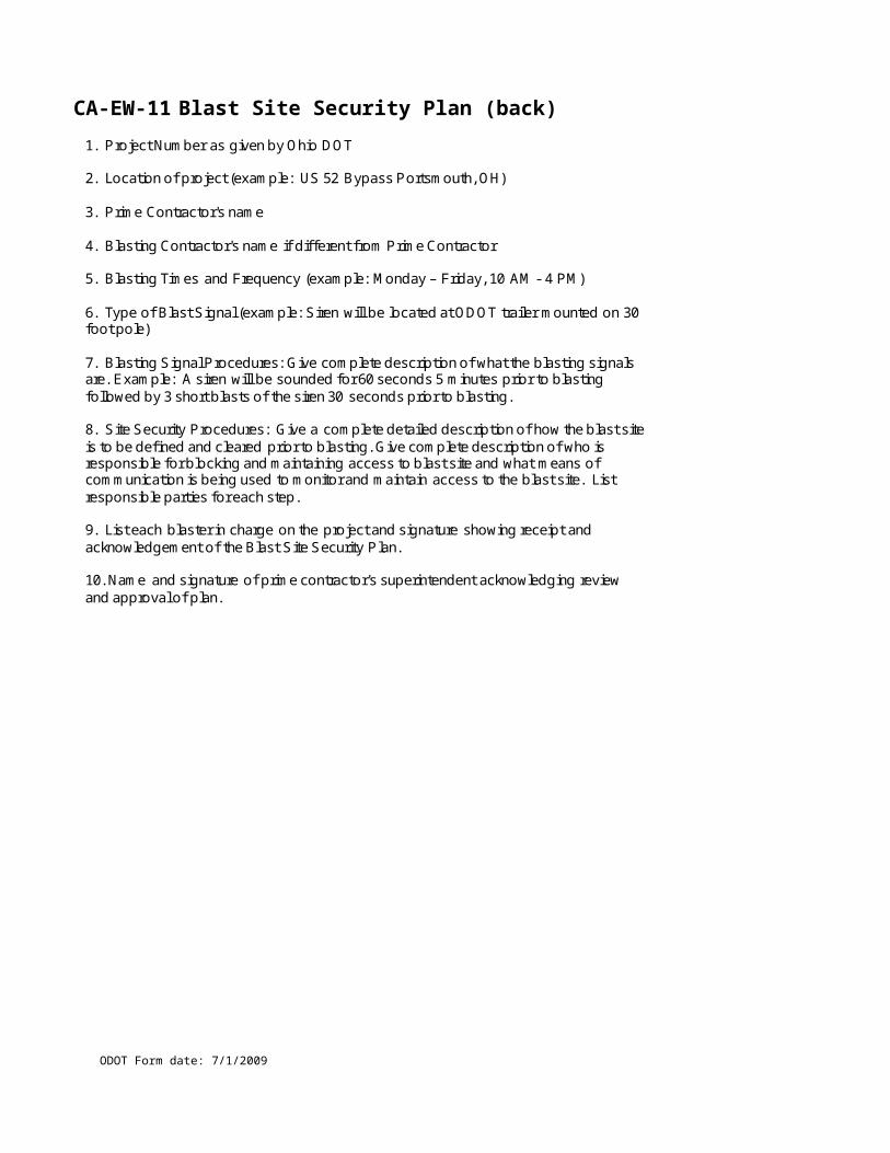
CA-D-3A ODOT Inspectors Daily Report
ODOT Form date: 7/1/2009
Project No: County/Route/Section: Report No:
Date: Weather: Temperature: Precipitation:
Contractor:
Sublet No: 1Wo Ws Wc Lost Day? Yes No
Hours: From /To Superintendent / Foreman Supervisor Skilled Other Total
Contractor:
Sublet No: 1Wo Ws Wc Lost Day? Yes No
Hours: From /To Superintendent / Foreman Supervisor Skilled Other Total
1DESCRIPTION OF WORK (DDCON)
1
1DAILY DIARY PAY ITEMS (DDWAP)
1Ref
#
EW
#
Part
Code
Plan
Page
Plan
Code Location Quantity Unit
1STATE EMPLOYEE HOURS (DDHRS)
1Employee Hours
Worked
Overtime
Hours Worked
Work Code Vehicle License No.
PE/PS Approval
CMS
Overtime Explanation:
Attachments: Y N Sketches/Calculations on reverse: Y N (DDRMK) Remarks on reverse:Y N
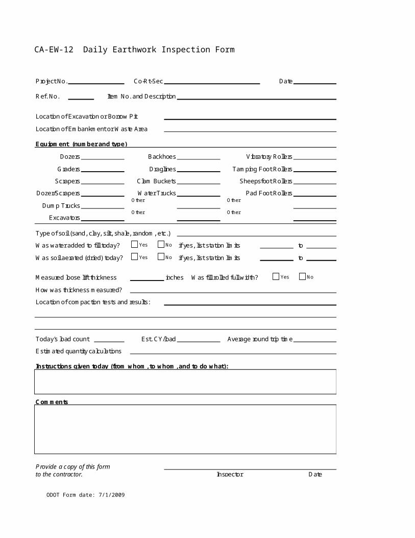
CA-D-3A ODOT Inspectors Daily Report (back)
ODOT Form date: 7/1/2009
1CONTRACTOR’S EQUIPMENT (DDCEQ)1Sublet
#
Equipment Type
Equipment
ID #
Idle Sublet
#
Equipment Type
Equipment ID #
Idle Sublet
#
Equipment Type
Equipment
ID#
Idle
1PAY ITEM NOTES (DDRMK):
1REMARKS ( MOT/C-95/ACCIDENTS - DDRMK):
1Inspector Signature:
1PE/PS Initials:

CA-D-3B ODOT Inspectors Daily Report
ODOT Form date: 7/1/2009
Project No: County/Route/Section: Report No:
Date: Weather: Temperature: Precipitation:
Contractor:
Sublet No: 1WO WS WC
Lost Day? Yes No
Hours: From /To Superintendent / Foreman Supervisor Skilled Other Total
1DESCRIPTION OF WORK (DDCON)
1
1CONTRACTOR’S EQUIPMENT (DDCEQ)
1Sublet
#
Equipment Type
Equipment
ID #
Idle Sublet
#
Equipment Type
Equipment ID #
Idle Sublet
#
Equipment Type
Equipment
ID#
Idle
1STATE EMPLOYEE HOURS (DDHRS)
1Employee Hours
Worked
Overtime
Hours Worked
Work Code Vehicle License No.
PE/PS Approval
CMS
Overtime Explanation:
Attachments: Y N Sketches/Calculations on reverse: Y N (DDRMK) Remarks on reverse:Y N

CA-D-3B ODOT Inspectors Daily Report (back)
ODOT Form date: 7/1/2009
1DAILY DIARY PAY ITEMS (DDWAP)
1Ref
#
EW
#
Part
Code
Plan
Page
Plan
Code
Location Quantity Unit
1PAY ITEM NOTES (DDRMK):
1REMARKS ( MOT/C-95/ACCIDENTS - DDRMK):
1Inspector Signature:
1PE/PS Initials / Date:
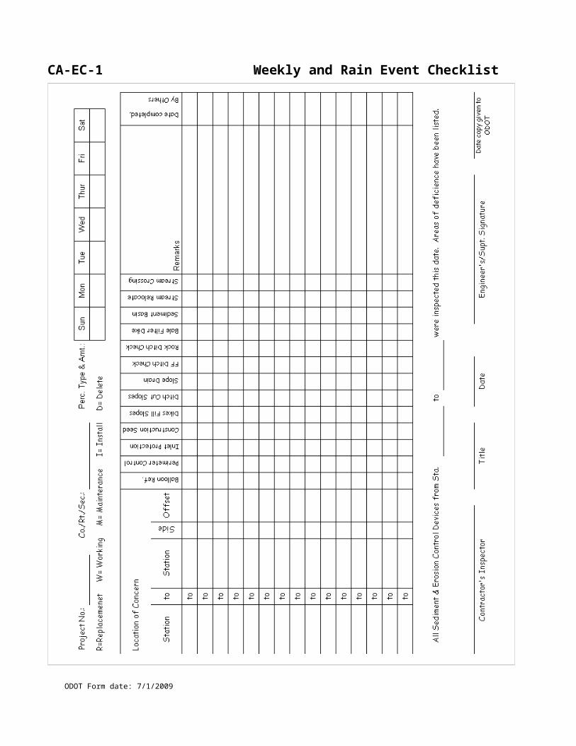
CA-D-4 ODOT P.E. / P.S. Daily Report
ODOT Form date: 7/1/2009
Project No: County/Route/Section: Date:
Temperature
High: Low: Precipitation: Rain / Snow / Ice / Fog
Lost day due to weather? Lost day due to other reason?
Reason:
1Contractor Date Work Started Date Work Stopped Work Complete(Yes/No)
Additional Pay Items1 (DDWAP)1Ref
#EW # Part
CodePlan Page
Plan Code
Location Quantity Unit
CA-D-4 ODOT P.E. / P.S. Daily Report (back)
ODOT Form date: 7/1/2009
1Project Activities1
1General Remarks [ ] Potential Claim [ ] C-95 Related [ ] Partnering Related
1P.E. / P.S. Signature:
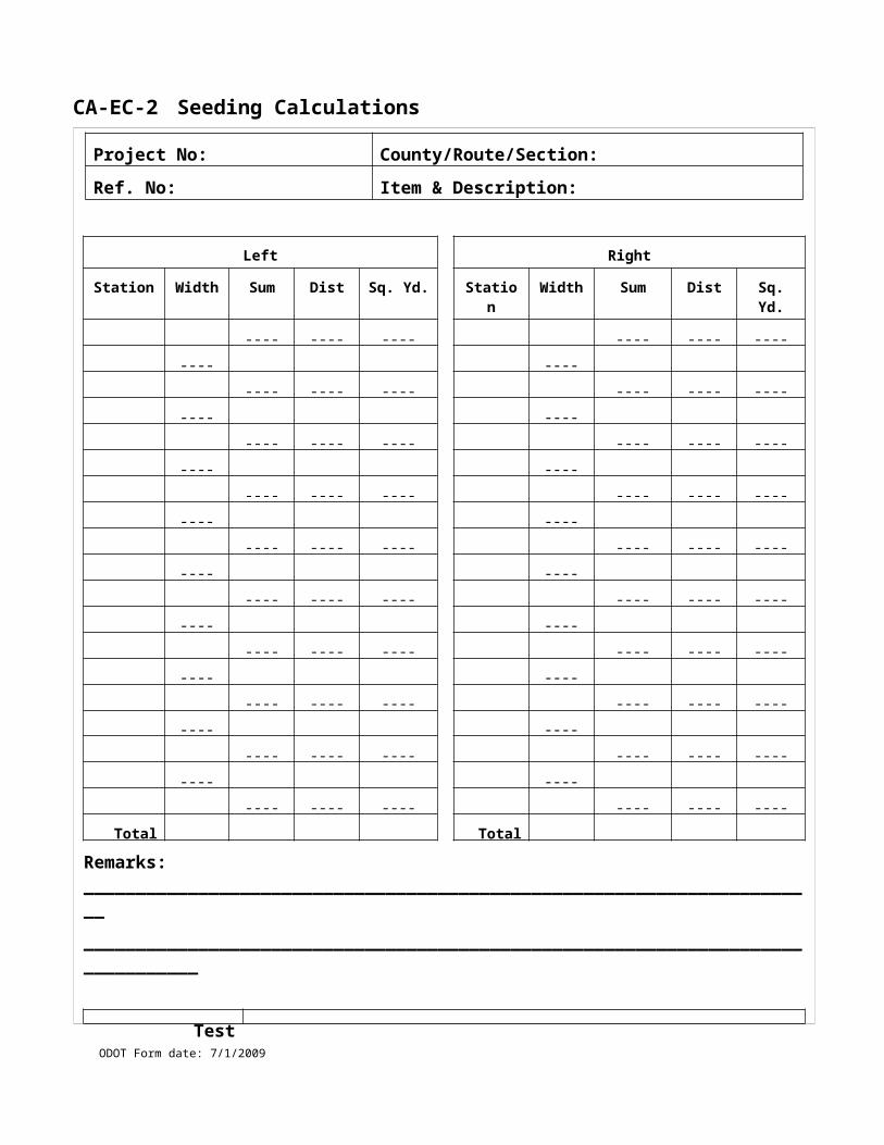
CA-D-5 Daily Account of Force Account Work
ODOT Form date: 7/1/2009
Project No: County/Route/Section: Date:
Contractor:
Sub-Contractor:
Description of Work:
LaborName Class From To Regular Hrs OT Hrs
Equipment A-Owned/ Bid Work, B-Rented/ Bid Work, C-Owned/ Non-Bid work, D-Rented/ Non-Bid work
A,B,C,D Hrs Used Hrs Idle Year Type Model HP, GVW, Capacity Gas/Diesel/Elect Equip No.
MaterialQuantity Unit Description Signatures/Date
Contractor:
ODOT:
Original to ODOT File, Copy to Contractor
CA-D-5 Daily Account of Force Account Work (back)
ODOT Form date: 7/1/2009
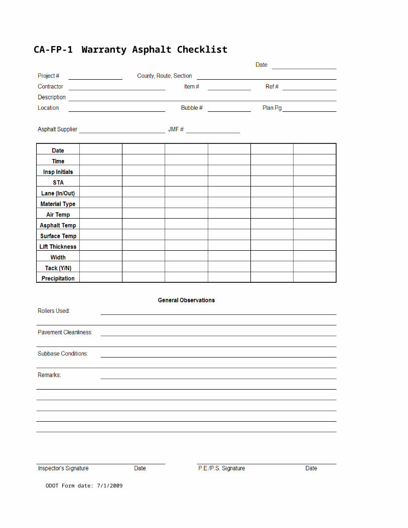
CA-D-6 Pavement Repair and Sawing Measurement
ODOT Form date: 7/1/2009
Project No: County/Route/Section:
Ref. No: Item & Description:
Station Station Lane Length (ft)
Width (ft)
Depth (in)
Quantity of Repair (sy)
Length of Sawing (ft)
Plan Page
TOTALS
Special Notes:
Inspected By: Date:
Checked By: Date:
CA-D-6 Pavement Repair and Sawing Measurement (back)
ODOT Form date: 7/1/2009
CA-D-7 Short Term Work Zone Review
ODOT Form date: 7/1/2009
Project No: County/Route/Section: Date:
Weather: Temperature: Time:Type Of Traffic Control: Road Closed / Lane Closed / Stationary / Moving / Shoulder / Other
Work performed by: ODOT / Permit / Utility / Contractor Name:
A. Traffic Control / Safety Devices Signs, Flaggers, Cones, Drums, Arrow Boards, Signals, PCMS, etc.
None Deficiency And Corrective Action To Be Taken Date Corrected
B. Traffic FlowEvidence of crashes, incidents, congestion points, delays, etc.
None Deficiency And Corrective Action To Be Taken Date Corrected
C. Conformance with Standards Tapers, buffer areas, etc
None Deficiency And Corrective Action To Be Taken Date Corrected
D. Interaction of Work Vehicles and Traffic Entering/exiting work zone, mud on road, etc
None Deficiency And Corrective Action To Be Taken Date Corrected
E. Storage of Equipment and Materials Protected or outside of clear zone
None Deficiency And Corrective Action To Be Taken Date Corrected
Action taken
Notification: Verbal / Written Correct By Date:
Section Requiring Action: A / B / C / D / E Corrected promptly? Yes / No
Work Stoppage Orders? Yes / No Date corrected:
Estimate Held? Yes / No Field Review by:
Copy to: DWZTM, County Manager, Contractor , Construction or Other (Identify)
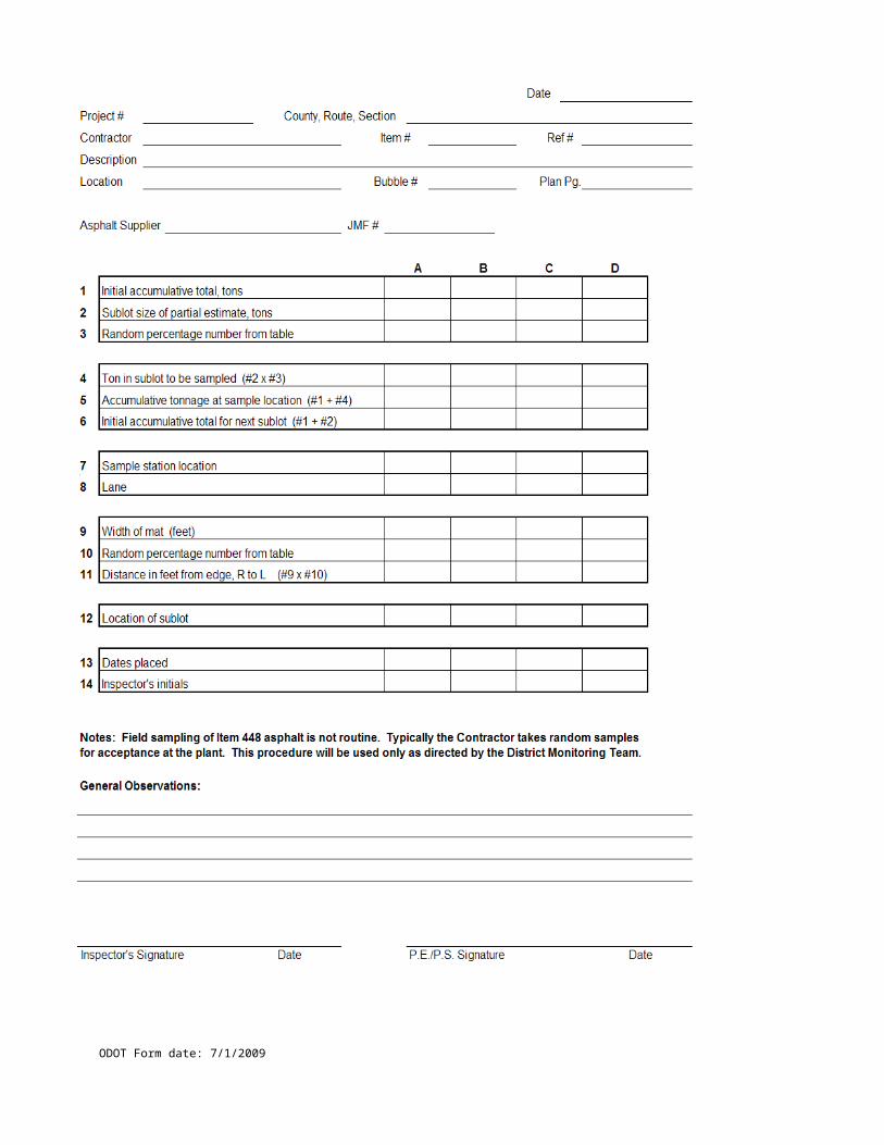
CA-D-7 Short Term Work Zone Review (back)
ODOT Form date: 7/1/2009
CA-D-8 Long Term Work Zone Review - 1/2
ODOT Form date: 7/1/2009
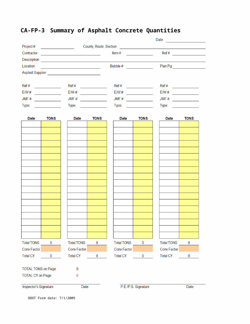
CA-D-8 Long Term Work Zone Review - 2/2
ODOT Form date: 7/1/2009
CA-D-9 Daily Concrete Pavement Documentation Form - 1 / 5
Project: ___________________ County/Route/Section: ___________________________
Reference #: _______________ Item #: ________________
Contractor: __________________________________________
Station: ______________ to _______________ Lane: _______
Placement Width: __________ Placement Depth: __________
Date: ____________
Temperature and Weather: __________________________________________
PCJMF: __________________________
SUBBASE
Subbase material and condition: ______________________________________
Was the subbase thoroughly moistened before placing concrete? __________ (451.06)
Method used to water subbase: __________________________________________________
JOINTS (451.08)
Longitudinal Joints (451.08A) – Tie Bars
Length: __________ Size: __________ Depth placed: __________
Are tie bars epoxy coated? __________
Method of placing tie bars: ______________________________________________________
Are tie bars being kept horizontal in the slab? ___________
Tie bar spacing? ___________ Number of tie bars placed per typical panel? ___________
Longitudinal joint located at _________ feet from left edge of slab
_________ feet from right edge of slab
ODOT Form date: 7/1/2009
CA- D-9 Daily Concrete Pavement Documentation Form - 2 / 5
Load Transfer Devices (451.08 B) - Transverse Joints
Dowel Length: __________ Diameter: __________ Depth placed: __________
Are dowel bars epoxy coated? __________
Were the dowel bars oiled? __________ Entire bar or alternating ends? _______________
Are dowel bars being kept in the proper alignment? ____________________________
Method of placing dowel bars? ________________________________________________
Dowel bar spacing? _______________ beginning ______________ from edge of slab
Number of dowels placed per panel? _________ for _________ panel width
_________ for _________ panel width
Transverse joint spacing: ______________
Expansion Joints (451.08C)
Dowel Length: __________ Diameter: __________ Depth placed: __________
Are dowel bars epoxy coated? __________
Were the dowel bars oiled? __________
Were expansion sleeves installed? __________
On opposite ends of adjacent dowels? _______
Transverse joint spacing: ______________
Construction Joints (451.08E)
Construction joint type: ______________________________________________________
Method of doweling construction joint: __________________________________________
Location of construction joint with respect to contraction joint: _______________________
ODOT Form date: 7/1/2009
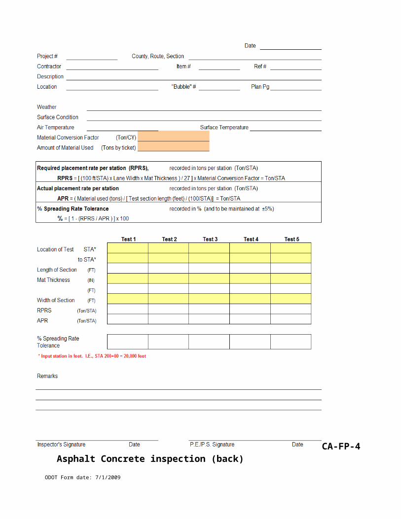
CA- D-9 Daily Concrete Pavement Documentation Form - 3 / 5
PLACING CONCRETE (451.06)
Method of Construction – Fixed Form or Slip Formed? ________________________________
Formed Construction
Forms made of steel? ___________
Form depth equal to pavement thickness? _______
Forms cleaned and oiled? _________
Slip Form Construction
Slip form paver make/ model: _________________________________________
Number of internal vibrators: __________________________________________
Vibrator monitors working? ___________
Were all vibrators working properly? _______
Vibration frequency range _______ to ______ ipm
Was vibrator information recorded? ________
Method of aligning paver: _________________________________________________
Paver advancement rate: ____________ feet/minute
Is the longitudinal face of the slab being kept vertical? ____________
Any projections or ridges exceeding tolerances in 451.03B? ____________
Method of depositing concrete:
Is a spreader required/used? _____________________________________________
Was its use waived? / Reason: _______________________________________________
ODOT Form date: 7/1/2009

CA- D-9 Daily Concrete Pavement Documentation Form - 4 / 5
FINISHING (451.09)
Hand finishing methods used: ____________________________________________________
Was 10’ straightedge used? _____________
Were pavement edges rounded? ___________
Micro texture type: _____________________ applied using: ____________________________
Macro texture type: _____________________ applied using: ____________________________
Tine groove spacing: ____________________ Tine depth: ______________________________
Were station numbers stamped into the shoulder pavement? ______________ Spacing? _______
Station number position: ________________________________________________________
CURING (451.10)
Method of applying curing compound: _____________________________________________
Curing compound required: Width = _____ (slab width) + 2 x _____ (slab thickness) = _____
Gallons Required = ________ (length) x ______ (width) / 150 = _________
Gallons Used = __________ (begin tank) - __________ (end tank) = ___________
Curing compound applied approximately ___________ minutes after final finishing
JOINT SAWING (451.08)
Was a HIPERPAV file submitted for this pour? ___________
HIPERPAV predicts early age cracking beginning at _____________ without joint sawing.
Joint sawing began at ____________
Method of sawing: Early-entry saw? ______ Wet Sawing? ________
Width of Saw Cut Depth of Saw Cut
Longitudinal Joints: _________________ ________________
Contraction Joints: _________________ ________________
ODOT Form date: 7/1/2009
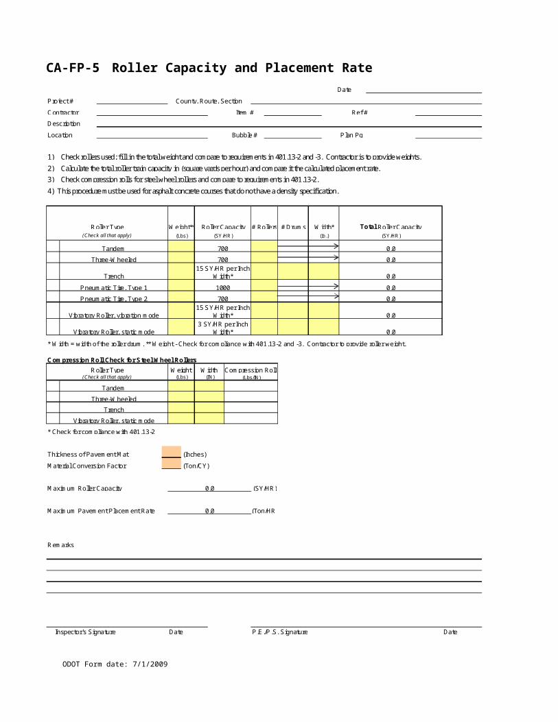
CA- D-9 Daily Concrete Pavement Documentation Form - 5 / 5
INSTRUCTIONS GIVEN TO THE CONTRACTOR
__________________________________________________________________________________________________________________________________________________________________________________________________________________________________________________________________________________________________________________________________________________________________________________________________________________________________________________________________________________________________________________________________________________________________________________________________________________________
COMMENTS
__________________________________________________________________________________________________________________________________________________________________________________________________________________________________________________________________________________________________________________________________________________________________________________________________________________________________________________________________________________________________________________________________________________________________________________________________________________________
Signature: ________________________________ Date: ___________________
ODOT Form date: 7/1/2009
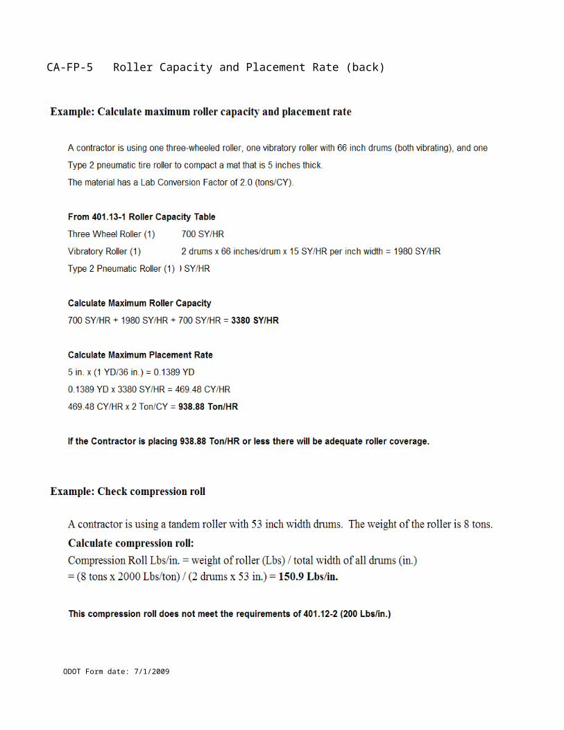
CA- D-9 Daily Concrete Pavement Documentation Form - (Back)
ODOT Form date: 7/1/2009

CA-L-1 Report of Electrical Tests
ODOT Form date: 7/1/2009
For Traffic Signals
Project No: County/Route/Section:
Ref. No: Item & Description:
Short Circuit Test (CMS 632.28C)
(Infinite or very high OHMS required)
Circuit Continuity Test (CMS 632.28D)
(Zero or negligible OHMS required)
1Pairs Measured 1OHMS 1Pairs Measured 1OHMS 1Pairs Measured Zero-1OHMS
1Pairs Measured Zero-1OHMS
Signal Cable Interconnect
Cable (7 cond.)
LOOP UNSPL. Interconnect
Cable (7 cond.)
1W/R 1W/R 1loop unspl. 1W/R
1W/ORG 1W/ORG 1loop unspl. 1W/ORG
1W/G 1W/G 1loop unspl. 1W/G
1W/BK 1W/BL 1 loop + L.I. 1W/BL
1R/ORG 1W/WBK 1 loop + L.I. 1W/WBK
1R/G 1W/BK 1 loop + L.I. 1W/BK
1R/BK 1R/ORG 1 loop + L.I. 1R/ORG
1ORG/G 1 R/G 1Signal Cable 1 R/G
1ORG/BK 1R/BL 1W/R 1R/BL
1G/BK 1R/WBK 1W/ORG 1R/WBK
1ETC. 1 R/BK 1W/G 1R/BK
1ORG/G 1W/BK 1ORG/G
1ORG/BL 1R/ORG 1ORG/BL
1ORG/WBK 1R/G 1ORG/WBK
1ORG/WB 1R/BK 1ORG/WB
1G/BL 1ORG/G 1G/BL
1ALL GRD G/WBK 1ORG/BK 1G/WBK
1G/BK 1G/BK 1G/BK
1Power Cable 1BL/WBK 1Power Cable 1BL/WBK
1W/BK 1BL/BK 1W/BK 1BL/BK
1W/R (3 cond.) 1WBK/BK 1W/R (3 cond.) 1WBK/BK
1BK/R (3 cond.)
Jumpered together
1(9 cond. ETC.)
Add sheet
1BK/R (3 cond.) 1 (9 cond. ETC.)
Add sheet
Test conducted by:
Inspected By: Date:
Checked By: Date:
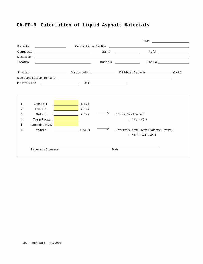
CA-L-1 Report of Electrical Tests (back)
ODOT Form date: 7/1/2009
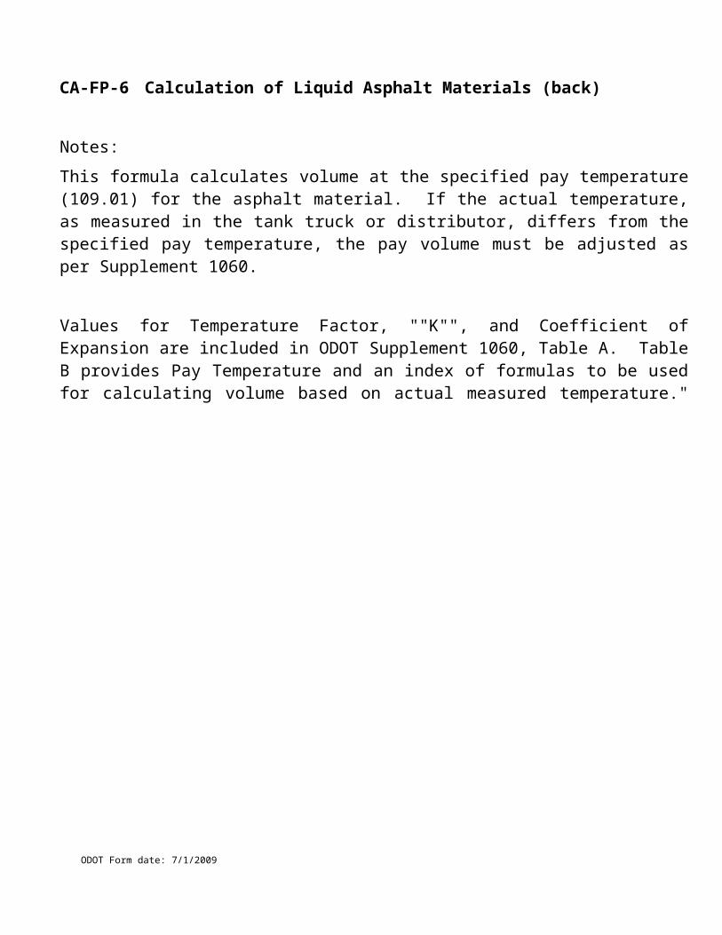
CA-L-2 Report of Electrical Tests
ODOT Form date: 7/1/2009
Signal-Ten Day Test (CMS 632.28G)
Project No: County/Route/Section:
Ref. No: Item & Description:
Test Conducted By: ______________ Representing _________________________Test Witnessed By:________________ Representing _______________________
Certification
I hereby certify that the above test was conducted in conformance with the plans and specifications for Project No.____________, that the test results as indicated below and that the requirements of the plans and specifications have been met.
Contractor’s Representative: _________________________________________Title: _________________________________________________________________________
Signal Control System Ten Day Performance Test
Time and Date Started: __________________________________________________________
Time and Date Completed: _______________________________________________________
Details of Outages, Trouble, Repairs, Etc., Including Locations:
_______________________________________________________________________________
_______________________________________________________________________________
_______________________________________________________________________________
_______________________________________________________________________________
_______________________________________________________________________________
NOTE: If this report does not include all of the (electrical) (lighting) systems proposed on the project, indicate here the separate circuits or components covered by this test:
_______________________________________________________________________________
_______________________________________________________________________________
_______________________________________________________________________________
_______________________________________________________________________________
Test Conducted By: ________________________ Representing: _________________________
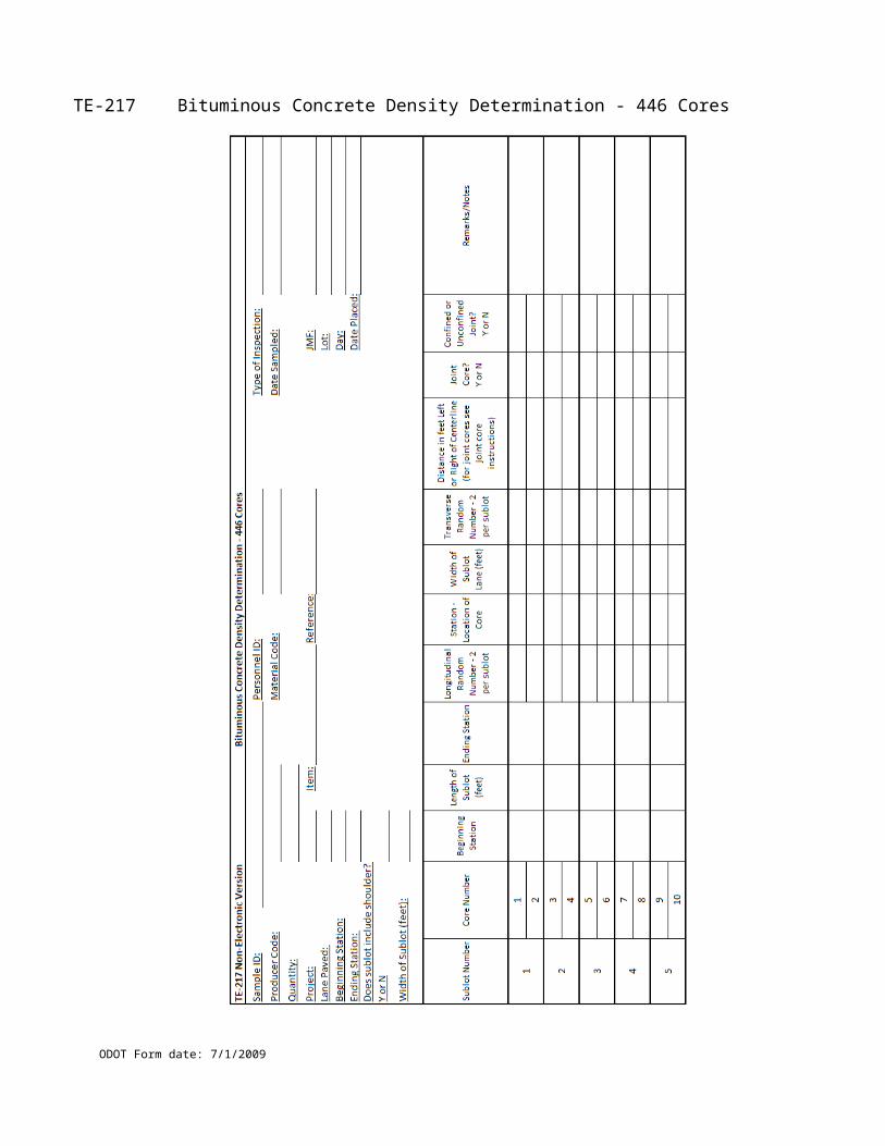
CA-L-2 Report of Electrical Tests (back)
ODOT Form date: 7/1/2009

CA-L-3 Report of Electrical Tests
ODOT Form date: 7/1/2009
Sign Lighting Test (CMS 625.19)Project No: County/Route/Section:
Ref. No: Item & Description:
Note: This report shall be accompanied by a written certification that test equipment used was last calibrated by an acceptable testing agency not more than 60 days prior to the date of the test.
1Ground Test [] Circuit Test []
1Location
1Light/Sign Structure No.
Circuit No. 1 Station 1Route, Street, Etc
1LT./RT. 1Resistance in:
Ohms- Megohms-
Test Conducted By: _______________________________ Date: ________________________
Representing: ____________________________________________________________________
Test Witnessed By: _____________________________________ Date: ___________________
Representing: ____________________________________________________________________
Certification
I hereby certify that the above test was conducted in conformance with the plans and specifications for Project No.____________, that the test results were as indicated above and that the requirements of the plans and specifications have been met.
Contractor’s Representative: ___________________________________ Date: ____________
Title: ___________________________________________________________________________
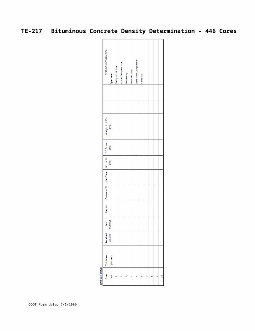
CA-L-3 Report of Electrical Tests (back)
ODOT Form date: 7/1/2009
CA-L-4 Report on Sign Lighting
ODOT Form date: 7/1/2009
(CMS 625.09 and CMS 631)Project No: County/Route/Section:
Ref. No: Item & Description:Ref Ground Rod Reading:
Ref Disconnect Switch Amps: Type Enclosure:
SIGN “A” - (Length) __________ X (Width) __________ = __________ SQ. FT.
Ref Ballast Type
Ref Lamp Size Type Quantity
Ref Lamp Size Type Quantity
HEIGHT: BOTTOM OF SIGN TO TOP OF PAVEMENT: __________
Ref Sign Wired Complete
SIGN “B” - (Length) __________ X (Width) __________ = __________ SQ. FT.
Ref Ballast Type
Ref Lamp Size Type Quantity
Ref Lamp Size Type Quantity
HEIGHT: BOTTOM OF SIGN TO TOP OF PAVEMENT: __________
Ref Sign Wired Complete
SIGN “C” - (Length) __________ X (Width) __________ = __________ SQ. FT.
Ref Ballast Type
Ref Lamp Size Type Quantity
Ref Lamp Size Type Quantity
HEIGHT: BOTTOM OF SIGN TO TOP OF PAVEMENT: __________
Ref Sign Wired Complete
SIGN “D” - (Length) __________ X (Width) __________ = __________ SQ. FT.
Ref Ballast Type
Ref Lamp Size Type Quantity
Ref Lamp Size Type Quantity
HEIGHT: BOTTOM OF SIGN TO TOP OF PAVEMENT: __________
Ref Sign Wired Complete
Test Conducted By:
Inspected by: Date:
Checked by: Date:
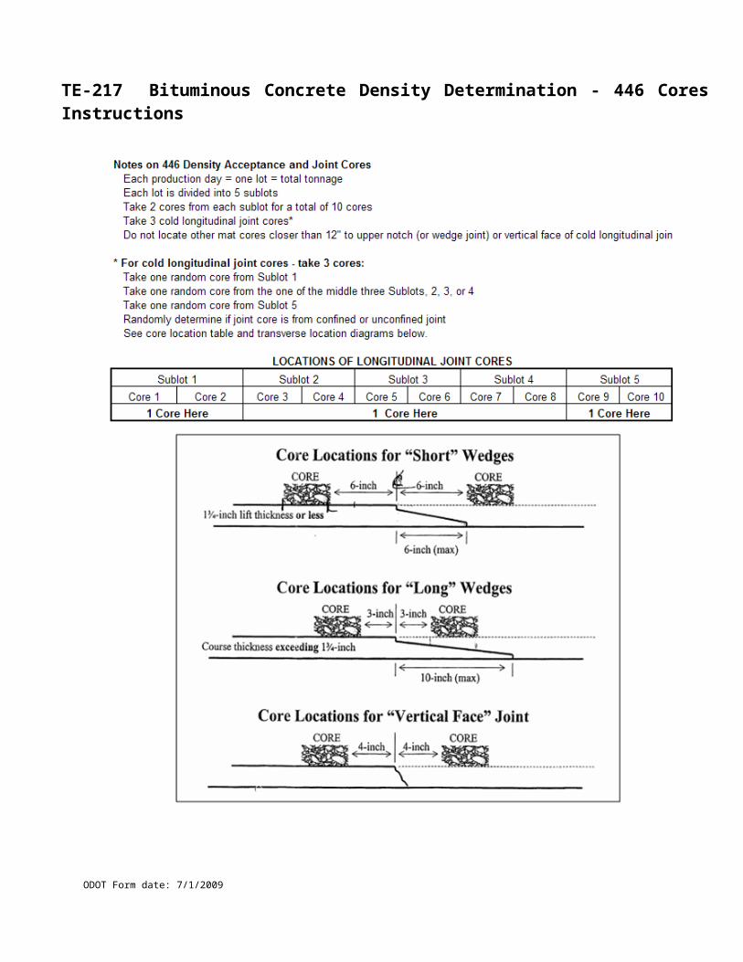
CA-L-4 Report on Sign Lighting (back)
ODOT Form date: 7/1/2009
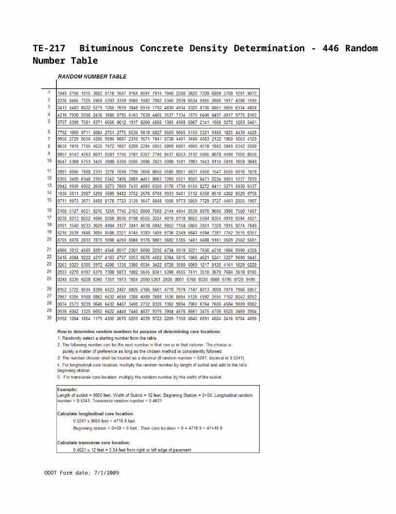
CA-L-5 Report on High Voltage Direct Current Tests
ODOT Form date: 7/1/2009
(CMS 625.19E and SS 1003)Project No: County/Route/Section:
Ref. No: Item & Description:
Circuit Number
Power 1 Power 2 Neutral Air Temperature
Relative Humidity
Notes: __________________________________________________________________________
________________________________________________________________________________
________________________________________________________________________________
Test Conducted By:
Inspected by: Date:
Checked by: Date:
CA-L-5 Report on High Voltage Direct Current Tests (back)
ODOT Form date: 7/1/2009
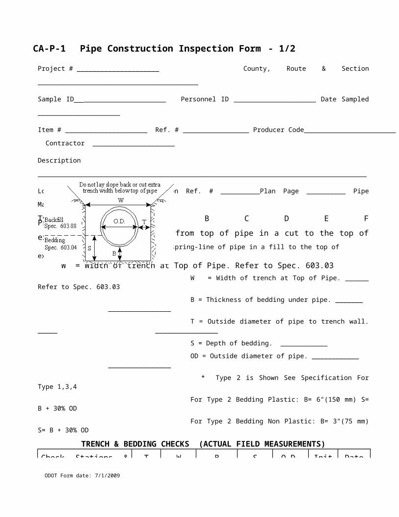
CA-T-1 DLS Report Format - Weight-Based System
ODOT Form date: 7/1/2009
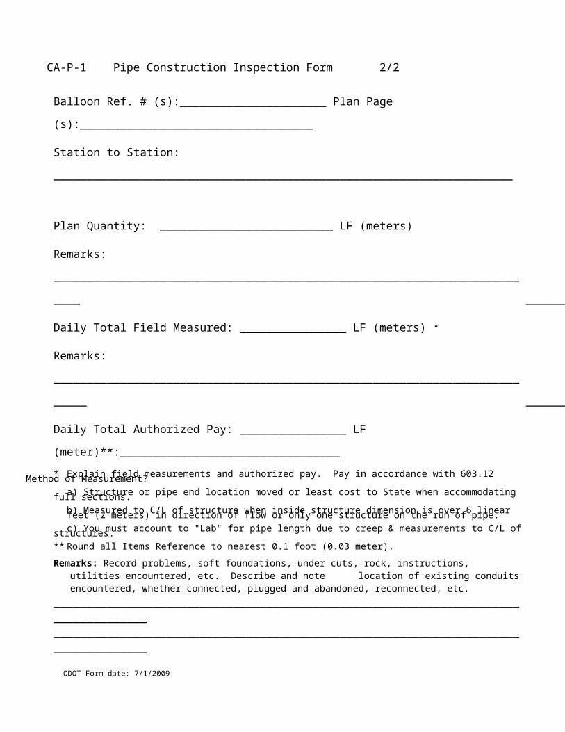
CA-T-2 DLS Short Report Format - Weight-Based System
ODOT Form date: 7/1/2009
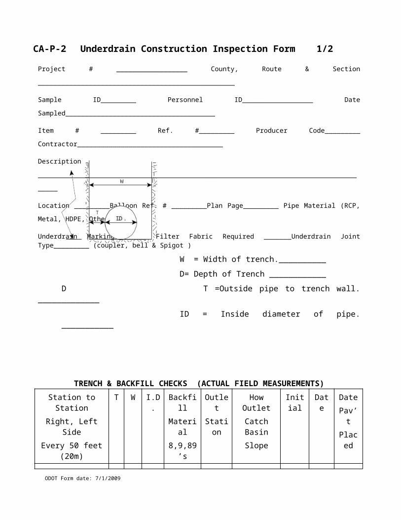
CA-T-3 DLS Report Format – Stroke Counter System
ODOT Form date: 7/1/2009
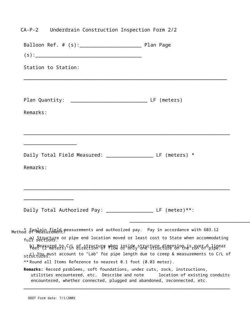
CA-T-4 DLS Short Report Format – Stroke Counter System
ODOT Form date: 7/1/2009
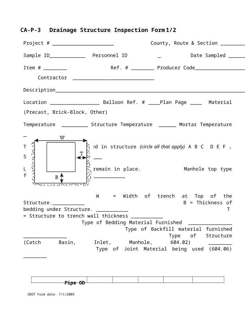
CA-T-5 DLS Report Format – Flow Meter Based System
ODOT Form date: 7/1/2009
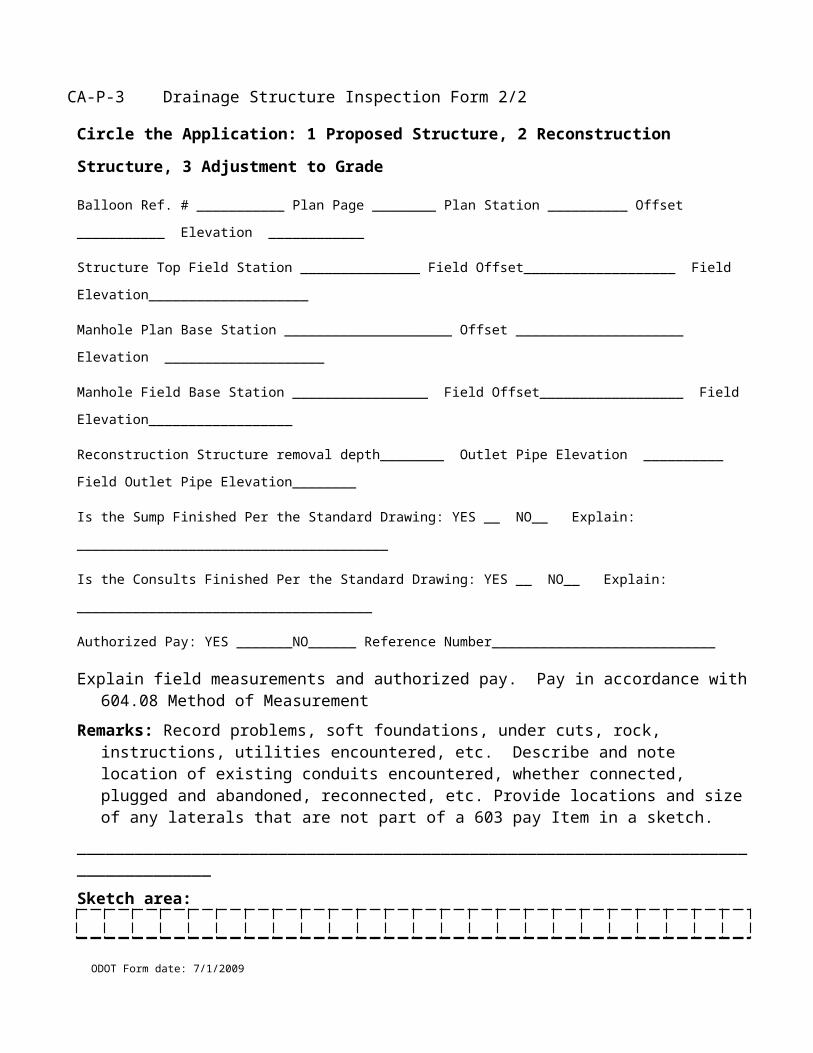
CA-T-6 DLS Short Report Format – Flow Meter Based System
ODOT Form date: 7/1/2009

CA-T-7 DLS Report Format – ThermoPlastic System
ODOT Form date: 7/1/2009
CA-T-8 DLS Short Report Format – ThermoPlastic System
ODOT Form date: 7/1/2009
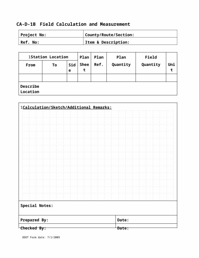
TE-31 Sample Data Envelope No: __________
Sample ID: __________ Sample Origin: _____________________ Personnel ID: _________
Type of Inspection: ______________________________________ Date Sampled: __________
P/S Code (1): _______________________________ at ________________________________
Mix Plant Code (1): __________________________ at ________________________________
Material Code: __________________________________________________________________
Brand Name: ___________________________________________________________________
Description 1: ___________________ 2: __________________ 3: _________________________
Represents Quantity (2): __________________________ Unit of Measure:________________
Number of Items: __________________________ Consigned to: _________________________
Sampled from: ______________________________ Mfg. Control Number: ________________
Responsible Location: ________________________________ Test Lab: ___________________
Assign To Project PO PO Ind Item Code Ref No Quantity
Lot/Day (3): ____________________________ JMF (3): _______________________________
Concrete Cylinder Specimen Numbers (4): _____________ Bill of Lading No: ____________
Remarks: ______________________________________________________________________
_______________________________________________________________________________
_______________________________________________________________________________
_______________________________________________________________________________
_______________________________________________________________________________
(1) Same materials are used at a Bituminous or PC Concrete mix plant and are sampled and tested by plant and not by project. For these samples the producer/supplier is identified in the P/S field and the mix plant where the material is sampled is identified in the mix plant field.
(2) Job control samples require a quantity.
(3) Rice and Extraction Samples require a JMF, 411 materials require Lot/Day No.
(4) Identifies concrete cylinders being shipped to the Test lab (TE-31 not to be entered into CIVIS - data already entered from corresponding TE-45)
ODOT Form date: 7/1/2009
TE-31 Sample Data (back)
ODOT Form date: 7/1/2009
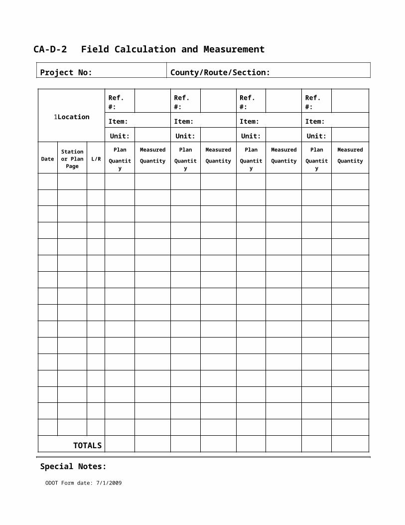
Noise Barrier Wall Shop Drawing Review Checklist
The purpose of this checklist is to assist the Engineer with the Department’s review of shop drawings submitted by the Contractor in accordance with Standard Bridge Drawing, NBS-1-09.
The shop drawings are signed, sealed and dated by an Ohio Registered Professional Engineer. See footnote ( ).
The Contractor has accepted the shop drawings in writing. See footnote (1).
The acceptance letter documents all issues raised by the contractor, fabricator and Department including disposition of issues. See footnote (1).
For absorptive walls, the absorptive wall material supplier is a pre-approved supplier in accordance with NBS-1-09 or all certified test data and performance history documentation has been provided and is in accordance with NBS-1-09. See footnote (1).
The shop drawing top of wall elevation at each panel meets or is above the plan requirements. See footnote ( ).
The shop drawing bottom of wall elevation at each panel meets or is lower than the plan requirements. See footnote (2).
The total panel height at each location meets the plan requirements and is consistent with the top and bottom of wall elevations as provided in the shop drawings. See footnote (2).
The shop drawing post height at each location meets the plan requirements. See footnote (2).
The shop drawing individual panel designs are in accordance with NBS-1-09. See footnote (3).
The shop drawing individual post designs are in accordance with NBS-1-09. See footnote (3).
The shop drawing wall alignment is in accordance with the contract requirements. See footnote (3).
The shop drawing material requirements are in accordance with NBS-1-09. See footnote (3).
The shop drawing aesthetic treatments are in accordance with the contract requirements, including alignment of horizontal joint lines for at least 96-ft. See footnote ( ).
The shop drawing base plate and anchor bolt requirements are in accordance with NBS-1-09. See footnote (3).
If all checklist items are met, mark documents as “ACCEPTED”.
Footnotes: 1. If missing, mark documents as “NOT ACCEPTED”. 2. Document all discrepancies and mark documents “ACCEPTED AS NOTED”. Resubmittal is not required.
3. Document all discrepancies and mark documents “ACCEPTED AS NOTED – RESUBMIT”.
ODOT Form date: 7/1/2009
Noise Barrier Wall Shop Drawing Review Checklist – (Back)
ODOT Form date: 7/1/2009
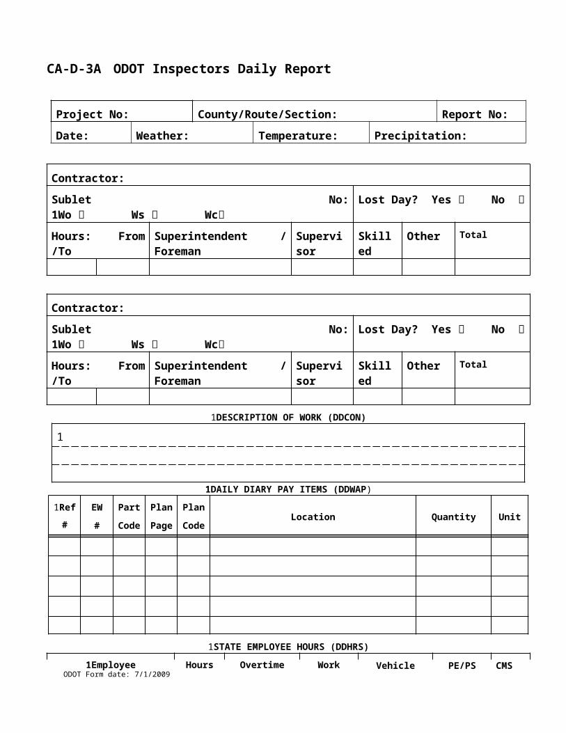
Preconstruction Meeting Agenda / Checklist, Page -1/2
Preconstruction Meeting Agenda/MinutesAttach signed attendance sheet with Name/Representing/Phone
Date of Conference: _________ Location: _______________________________Name of Person Presiding over meeting: ________________________________State Project No: __________, C-R-S: _____________, PID: ________________Project Type / Description: ___________________________________________Bid date: _________ Awarded date: _________ Completion date: ____________Estimate dates: __________ and _____________ of each month, accepted payroll and certification of estimates is required (109.09)
Distribute and discuss applicable Plans, Specifications, Addenda information: _______________________________________________________________________________________________________________________________________
Status of Utilities, RR and Local requirements: ________________________________________________________________________________________________________________________________________________________________
107.20, 108.01, DBE/EEO/Prevailing wage bulletin and submittal discussion: _______________________________________________________________________________________________________________________________________
PN 10, ARRA (Stimulus Project) data submission requirements discussion: _____ ____________________________________________________________________________________________________________________________________
107.19, SS832 - Erosion Control and Best Management Practices discussion: ___ ____________________________________________________________________________________________________________________________________
Initial Schedule received? _____ (Bar Chart or CPM)
Use extra pages as necessary for each topic.
ODOT Form date: 7/1/2009
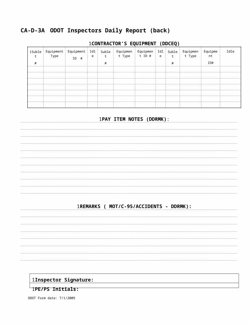
Preconstruction Meeting Agenda / Checklist, Page -2/2
Prime Contractor: ____________________________Phone No: ______________Superintendent: ______________________________Phone No: ______________Normal Work Hours: _________ to _____________ WeekdaysNormal Work Hours: _________ to _____________ WeekendsExpected Construction Start Date: ______________Locations, Dates, and Descriptions of major work phases: _______________________________________________________________________________________________________________________________________________________105.13, Haul roads designated: ____________________________________________________________________________________________________________________________________________________________________________105.16, Borrow/ Waste/ Agreements: _______________________________________________________________________________________________________________________________________________________________________108.02, List Subcontractors to be used: __________________________________ ____________________________________________________________________________________________________________________________________108.02, AC / PCC plants to be used: ____________________________________ ____________________________________________________________________________________________________________________________________108.02, List of major material suppliers: _____________________________________________________________________________________________________________________________________________________________________208.12, Blast prequalification information: _______________________________ ____________________________________________________________________________________________________________________________________501.04, List of steel fabricators and precast concrete fabricators: ______________ ____________________________________________________________________________________________________________________________________514.09, List of MSDS for all paints, thinners, and abrasives: _________________ ____________________________________________________________________________________________________________________________________641.04, Method of DLS for Traffic Paint data reporting: _____________________ ____________________________________________________________________________________________________________________________________
Distribute the Preconstruction Minutes with all attachments to: Project Engineer, Prime Contractor Superintendent, Designer, Construction Office, LPA, and others expressing interest.
ODOT Form date: 7/1/2009