Embed Size (px)
Citation preview
1 INTRODUCTION
An understanding of groundwater flow is a critical factor for most underground construction projects and engineering applications. Groundwater flow through porous soil and rock occurs within the mate-rial matrix while groundwater flow in a fractured crystalline rock is typically defined by relatively high groundwater flow within fractures compared to the aquifer matrix, i.e. the rock itself. While the overall groundwater flow through the fractured rock mass may be typically low there is the potential for high groundwater ingress if highly transmissive fractures are intersected, and this can have signifi-cant financial and programme implications for excavation and tunnelling projects.
The Bukit Timah Granite forms one of the dominant geological formations in Singapore and is the lo-cation for numerous existing and future underground infrastructure. Groundwater issues are a frequent problem for excavations in the rock partly due to insufficient hydrogeological assessments and partly due to the high level of uncertainty and risks associated with the formation’s hydrogeological proper-ties.
Previous studies on the engineering geology and the hydrogeology of the Bukit Timah Granite (Pfeiffer, 1975; Zhao, 1998; and Zhou, 2001) indicated that the rock mass was typically massive and has a low hydraulic conductivity of 10-10-10-8m/s, with isolated discontinuity zones showing conduc-tivity values of 10-8-10-6m/s. The majority of studies mentioned predominantly focused on ground in-
Assessment of Hydraulic Conductivity and Groundwater Flow Models in the Bukit Timah Granite
Andrew Forsythe Mott MacDonald, Singapore
Nina Pearse – Hawkins Mott MacDonald, Singapore
ABSTRACT: Geotechnical investigations in the Bukit Timah Granite have frequently misinterpreted thehydrogeological conditions and fail to identify critical highly permeable zones with high flow rates oftenencountered during excavation and tunnelling works. This failure is a combination of inadequate inves-tigation, and poor understanding of the Bukit Timah Granite and its complex hydrogeological regime.The implications are significant to construction projects and can contribute to potential instability in the excavation, significant drawdown and settlements.
Studies of the Bukit Timah Granite show that it exhibits a multi-layered weathering profile typical of ig-neous bodies in tropical conditions with multiple structural features including fracture and fault zones frequently present. Groundwater flow in the Bukit Timah Granite is typically via secondary flow i.e.concentrated along the interconnected discontinuities in the rock; each layer or zone may exhibit its ownhydrogeological parameters and this combination of factors must be considered to accurately modelgroundwater flow. Geological and hydrogeological investigation data from throughout Singapore hasbeen assessed and applied to basic continuum and discontinuum hydrogeological flow models. These models, as well as numerical modelling techniques, are critiqued for their practical suitability, minimuminput data requirements and ability to quantify groundwater flow. In addition, the various procedures forundertaking hydrogeological investigations are outlined in light of the flow methods assessed and in-clude advice pertaining to when and where to focus hydrogeological investigations for different scenari-os and objectives.
Underground Singapore 2014
vestigation works in central and northern areas of Singapore sited for potential rock cavern feasibility assessments. However, rock conditions underlying transport corridors, frequently located in valleys and along drainage paths, where potential future underground infrastructure may be sited, typically at much shallower depths than rock caverns, are often quite different geologically and may exhibit a greater degree of weathering and fracturing. As such this study generally focuses on hydrogeological conditions in the upper 70m of the subsurface and ground investigation data used is predominantly from roadside locations below which future underground infrastructure may be constructed.
The aim of this paper is to summarise how groundwater typically flows in the Bukit Timah Granite, show typical hydraulic conductivity values for the shallow sections of the formation, illustrate possible methods to quantify flows, give example methods for future ground investigations, and highlight the risks and limitations with the methods to investigate and quantify the hydrogeological regime.
2 GEOLOGICAL UNDERSTANDING OF THE BUKIT TIMAH GRANITE
2.1 General Background and Geological Setting
The Bukit Timah Granite (BTG) is a large plutonic igneous complex of generally granitic rocks likely to be associated with island arc magmatism and formed by multiple phases of emplacement and assim-ilation. The body contains a variety of lithologies including granite, granodiorite, diorite and gabbro, along with dyke intrusions, enclaves and xenoliths typically comprising dolerite, andesite, dacite and rhyolite, frequently encountered throughout the body. The complex also contains numerous structural features including faults and fracture zones of various scales.
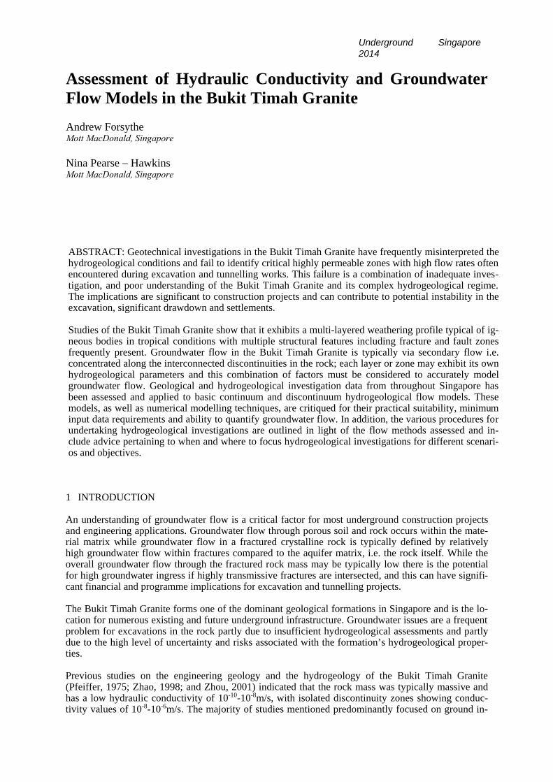
The BTG is the most dominant geology in Singapore and is encountered throughout much of the island although it is predominantly associated with the central areas of the island where the topographic relief is greatest. The general geological distribution for Singapore is as shown in Figure 1.
Figure 1. Simplified Solid Geology of Singapore. Figure 2. Simplified weathering profile of BTG – Bukit Timah Granite; JF – Jurong Formation; tropically weathered igneous rocks. After Little, OA – Old Alluvium. Superficial Geology not detailed. 1969.
Groundwater levels in the BTG typically range from 0.5m to 10mbgl depending on the setting but are most commonly anticipated to be around 3-5mbgl. Groundwater levels are likely to fluctuate with pre-cipitation volumes but as Zhao (1998) notes, rainfall in Singapore is generally fairly uniform through-out the year and groundwater level seems relatively stable.
2.2 Weathering Profile
The near surface BTG generally exhibits a multi-layered weathering profile typical of igneous bodies in tropical conditions. The generalised weathering profile is as shown in Figure 2 and the classification follows BS5930:1999, shown in Table 1. The weathering profile as described generally extends to
considerable depth with GIII rock head level typically encountered around 20-30mbgl, and has been encountered to depths of more than 60m (Zhou 2001). The rock head is typically undulating with fre-quent domes and valleys but generally follows the topography.
Table 1. Bukit Timah Granite Weathering Grades
Grade Classifier Typical Characteristics from BS5930:1999
Typical Descriptions from Bukit Timah Granite
GVI Residual Soil
Soil derived by in situ weather-ing but retaining none of the original texture or fabric.
Residual soil recovered as very soft to very stiff slightly gravelly fine to coarse sandy SILT OR loose to dense slightly silty, slightly gravelly fine to coarse SAND.
GV Completely Weathered
Considerably weakened. Slakes. Original texture apparent.
Completely weathered to stiff to hard fine to coarse sandy SILT OR dense to very dense fine to coarse SAND.
GIV Highly Weathered
Large pieces cannot be broken by hand. Does not readily dis-aggregate (slake) when dry sample immersed in water.
Highly weathered, completely discoloured rock to very dense silty SAND and GRAVEL with intact rock fragments, OR highly fractured rock with low SCR and very low RQD – generally less than 10%, usually 0%.
GIII Moderately Weathered
Considerably weakened, pene-trative discolouration. Large pieces cannot be broken by hand.
Moderately weathered, fractured, moderately strong to extremely strong rock. Noticeable dis-colouration. Makes a dull or slight ringing sound when struck by hammer.
GII Slightly Weathered
Slight discolouration, slight weakening.
Slightly weathered, moderately to slightly frac-tured, strong to extremely strong rock.
GI Fresh Unchanged from original state. Fresh very strong to extremely strong intact rock with original fractures.
As is shown, the weathering grades generally decrease with depth although downhole weathering is common below the rock head level and corestones are frequently encountered above the rock head. The upper GVI and GV layers can be considered soils, the underlying GIV represents a transition zone and may comprise highly weathered weakened intact rock, highly fractured rock, or an apparent mix of GV soils and GIII rocks. In engineering terms the layer is generally considered a soil. Below the GIV and the upper soils in situ rock of GIII to GI is generally encountered with a variable amount of fractures present. The weathering profile may not be complete and the transition from residual soil to strong in situ rock is frequently rapid.
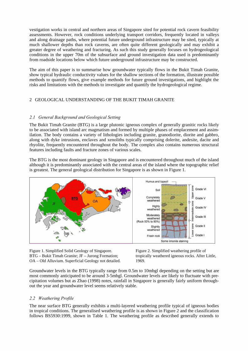
It is further noted that with increased weathering the materials exhibit increased porosity, particularly with respect to the soils. Cook (2003) classifies porous and fractured rocks as shown in Figure 3. From this example, it may be reasonable to generally classify the weathering grades of the BTG as follows:
GVI to GV – Homogeneous to Heterogenous Porous Media; GIV – Fractured Porous Media; GIII to GI – Purely Fractured Media (although all grades will exhibit some porosity).
Figure 3. Representation of porous and fractured rocks (Cook 2003)
2.3 Fractures and Joints
The near surface BTG, discounting the overlying GVI and GV soil mass, is considered to be a frac-tured rock mass with a varying degree of fractures, typically reducing in quantity with depth.
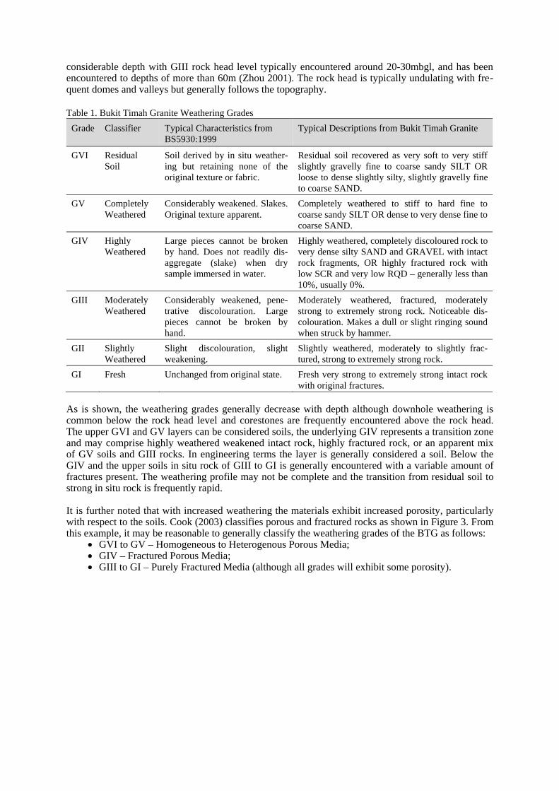
Zhao (1998) reported that there are generally three to four joint sets in the BTG with dominant sub vertical joint sets striking NNW-SSE, NNE-SSW and NW-SE. However, in near surface levels, joints may be encountered in numerous orientations including horizontal and sub-horizontal geometries, probably associated with near surface de-stressing. As such the sub-vertical joints may be considered more mature. Recent investigations utilising down hole optical televiewer methods show a large scatter of data but show a clear dominance of joints striking W-E and NE-SW as is shown in Figure 4. These results roughly correlate with recent hydraulic fracture investigations, undertaken as part of ground in-vestigations for future underground infrastructure, which show a principal horizontal stress direction predominantly oriented SW-NE. Both the televiewer and hydraulic fracture investigations were under-taken in east central Singapore running roughly between Woodlands in the north and Balestier in the south-central areas. It is, however, noted that televiewer surveys down vertical boreholes are more prone to statistically over representing the horizontal and shallow angle joints and fractures so that the vertical joints, such as those reported by Zhao (1998) may have been missed more easily.
Figure 4. Rosette and contoured pole plots of more than 6000 joints recorded by optical televiewer. Rosette plot shows strike of joints with dip angles of 70° or greater. Contour plot includes all discontinuities >30° dip.
Other fracture parameters are sometimes difficult to derive from standard ground investigation works but joints typically appear rough and planar to slightly undulating in core samples. Phyo et al (2014) reports from direct excavations in similar locations to the place where the GI described in Section 2.3 was undertaken and states that joints are typically found to be rough planar and of medium persistence (i.e. 3-10m) although a high level of variance is encountered.
3 GROUNDWATER FLOW IN FRACTURED ROCK
3.1 Understanding of groundwater flow in fractured rocks
Flow in fractured rock, including the Bukit Timah Granite, is predominantly via interconnected dis-continuities or fractured fault zones (i.e. secondary porosity), with primary porosity (flow through pore spaces in the solid rock mass) either non-existent or considerably less pronounced. The distinguishing characteristics of fractured rock aquifers is often large variability in hydraulic conductivity between the fracture and the rock matrix, and anisotropic flow patterns. While water velocities through individ-ual fractures can be high overall the volumetric aquifer flow can be low if fractures occupy a small percentage of the rock mass.
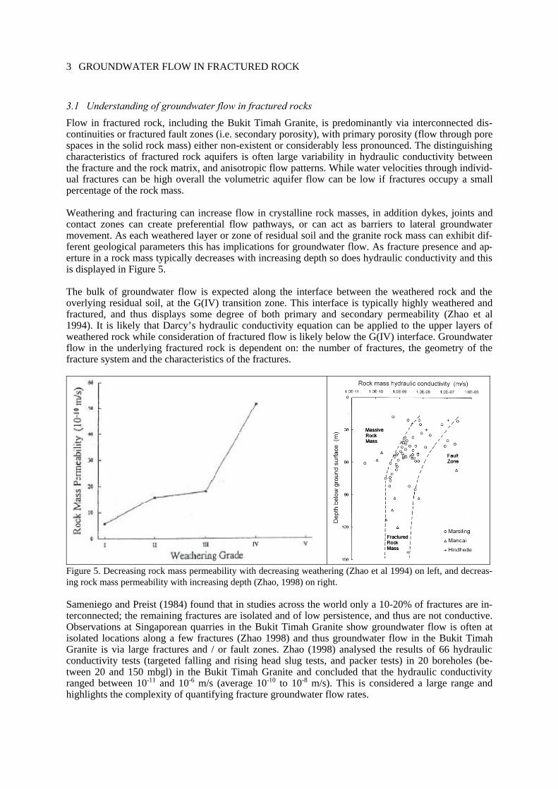
Weathering and fracturing can increase flow in crystalline rock masses, in addition dykes, joints and contact zones can create preferential flow pathways, or can act as barriers to lateral groundwater movement. As each weathered layer or zone of residual soil and the granite rock mass can exhibit dif-ferent geological parameters this has implications for groundwater flow. As fracture presence and ap-erture in a rock mass typically decreases with increasing depth so does hydraulic conductivity and this is displayed in Figure 5.
The bulk of groundwater flow is expected along the interface between the weathered rock and the overlying residual soil, at the G(IV) transition zone. This interface is typically highly weathered and fractured, and thus displays some degree of both primary and secondary permeability (Zhao et al 1994). It is likely that Darcy’s hydraulic conductivity equation can be applied to the upper layers of weathered rock while consideration of fractured flow is likely below the G(IV) interface. Groundwater flow in the underlying fractured rock is dependent on: the number of fractures, the geometry of the fracture system and the characteristics of the fractures.
Figure 5. Decreasing rock mass permeability with decreasing weathering (Zhao et al 1994) on left, and decreas-ing rock mass permeability with increasing depth (Zhao, 1998) on right.
Sameniego and Preist (1984) found that in studies across the world only a 10-20% of fractures are in-terconnected; the remaining fractures are isolated and of low persistence, and thus are not conductive. Observations at Singaporean quarries in the Bukit Timah Granite show groundwater flow is often at isolated locations along a few fractures (Zhao 1998) and thus groundwater flow in the Bukit Timah Granite is via large fractures and / or fault zones. Zhao (1998) analysed the results of 66 hydraulic conductivity tests (targeted falling and rising head slug tests, and packer tests) in 20 boreholes (be-tween 20 and 150 mbgl) in the Bukit Timah Granite and concluded that the hydraulic conductivity ranged between 10-11 and 10-6 m/s (average 10-10 to 10-8 m/s). This is considered a large range and highlights the complexity of quantifying fracture groundwater flow rates.
4 GROUNDWATER FLOW MODELS
The heterogeneity and anisotropy of fractured rock aquifers complicates assessments of flow; two methods are proposed that build on relatively simple equations relating to groundwater flow and frac-ture characteristics.
4.1 Continuum approach
The continuum approach assumes that the fractured mass is hydraulically equivalent to a porous medi-um, and thus relies on the application of Darcy’s law. This is considered an ‘equivalent porous medi-um approach’ and hydraulic properties of the system are modelled using equivalent coefficients (i.e. permeability, porosity) to represent a volume average behavior of fractures within a fractures rock mass (Cook 2003).
At a microscopic scale the value of porosity varies considerably, i.e. the sample may be all solid or all pore, however as the sample size increases there may no longer be any variations in the sample. This is described as the representative elementary volume (REV) and is a volume of sufficient size to accu-rately represent a value without any significant statistical variations. In reality there is likely to be het-erogeneities within fractured rocks and while an average value can be obtained the variance about the mean will increase with the scale of the problem and it is likely there is no single value that can be as-signed to represent faithfully the material properties. The concept states if a large enough volume of a fractured geological material is analysed it will behave mathematically like a porous medium. Essen-tially the variation in small scale features will decrease as the sample volume increases so that the final representative volume in achieved.
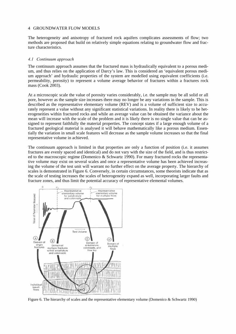
The continuum approach is limited in that properties are only a function of position (i.e. it assumes fractures are evenly spaced and identical) and do not vary with the size of the field, and is thus restrict-ed to the macroscopic regime (Domenico & Schwartz 1990). For many fractured rocks the representa-tive volume may exist on several scales and once a representative volume has been achieved increas-ing the volume of the test unit will warrant no further effect on the average property. The hierarchy of scales is demonstrated in Figure 6. Conversely, in certain circumstances, some theorists indicate that as the scale of testing increases the scales of heterogeneity expand as well, incorporating larger faults and fracture zones, and thus limit the potential accuracy of representative elemental volumes.
Figure 6. The hierarchy of scales and the representative elementary volume (Domenico & Schwartz 1990)
Application of a continuum approach does not require the details of individual fractures; use of this method for large scale problems requires data that is also large scale. The continuum approach relies on groundwater flow equations that are applicable to most granular material and can be expressed in terms of hydraulic head using Darcy’s law, where the velocity of flow is proportional to the hydraulic gradient: Q = -KA (dh/dl)
Q = groundwater flow (m3/time) K = constant of proportionality (a function of the medium and the fluid properties) A = cross sectional area of flow (m2) dh/dl = hydraulic gradient (the difference in hydraulic head between two points divided by the dis-tance between these points, dimensionless) (Fetter 2014).
This law implies a linear relationship, homogeneous conditions and assumes flow is laminar. Varia-tions of this equation should be implemented if flow is in steady state or if flow is generated from leakage from overlying or underlying aquifers.
Typically field measurements of hydraulic conductivity (the rate at which water moves through a ma-terial, m/time) are obtained and these can be used to determine transmissivity, or the amount of water that can be transmitted horizontally through a unit width of a fully saturated aquifer under a hydraulic gradient of 1.
T = bK
T = Transmissivity (m2/d) b = saturated thickness of the aquifer (m) K = hydraulic conductivity (m/d)
4.2 Discrete approach
In contrast to the equivalent porous medium approach, the discrete network approach accounts for the details of individual fractures. The discrete, or discontinuum, approach assesses and calculates flow in individual fractures or fracture sets. If fracture networks are complex it is impractical to characterise the system by summing individual fractures, especially as many fracture properties are difficult to ac-curately measure. This approach has three challenges:
Information about the fracture orientation, density, degree of connectivity, aperture opening and smoothness is required. As these elements are likely to be variable fracture generalisa-tions and averaging need to be made.
In large aperture fractures the flow may be turbulent rather than laminar, and thus the applica-tion of Darcy’s law is no longer applicable.
Values of hydraulic conductivity will vary with changes in the 3-D stress field and fluid pres-sure.
The Cubic Law states that for a given gradient in head, flow through a fracture is proportional or de-pendent to the cube of the average fracture aperture; this law is valid where fluid pressure effects are not important. This equation also assumes that the flow rate is directly proportional to the pressure gradient. Romm (1966) developed the following equation to calculate the volumetric flow rate for lam-inar flow between two smooth parallel plates:
ρwgb3
K = 12µ
K = hydraulic conductivity ρ w = density of water g = gravitational acceleration b = aperture (Nb is the planar porosity) µ = fluid viscosity
There are iterations of the Cubic Law that account for fracture roughness.
Snow (1968) developed the following equation to calculate equivalent hydraulic conductivity or per-meability for a set of planar fractures:
ρwgNb3 Nb3
K = 12µ or k = 12
N = number of joints per unit distance across the rock face (L-1) k = permeability.
In actual conditions, it is unlikely that fractures would represent parallel plates and due to connectivity, infilling and variation in fracture aperture a more accurate flow model may involve localised flow channeling. However, such conditions are difficult to model due to their complexity as well as the ina-bility to gather sufficient data on the required input parameters, and such models must be assessed us-ing a more probabilistic approach.
4.3 Numerical Models
Deterministic numerical models utilise the equations outlined in Sections 4.1 and 4.2 to synthesise known data and predict groundwater conditions. Modelling allows for a bigger scale conceptual under-standing of a system behavior compared to analytic equations, but relies on a sufficient quantity and quality of field data for relatively accurate results (Fetter 2014). Modelling can also be used to predict the outcomes of hypothetical flow situations. The physical conditions of the aquifer, including the fea-tures controlling flow (i.e. the geological layers and their extent) and flow parameters (e.g. hydraulic conductivity, specific storage, porosity) require investigation. An inherent problem of modelling is the scale at which the model is applied and the scale of the input field data; difficulties arise when the scales do not match (Cook 2003).
Numerical models will vary depending on the scale of interest and the purpose of the model. The scale of interest is important, as fractures can be connected on a large scale but may be dominated by either a small number of large fractures or a large number of small fractures.
In an equivalent porous medium approach individual fractures are not explicitly defined in the model, rather the heterogeneity of the fractured rock system is modelled using regions of an equivalent porous medium (or representative elementary volumes) (Cook 2003) as described in Section 4.1. This tech-nique is best employed in steady state systems and assumes the representative elementary volume is defined. This is a single porosity approach with a limited ability to model anisotropy. MODFLOW, developed by the United States Geological Survey and FEFLOW are three-dimensional (3D) finite-difference groundwater models (i.e. uses discrete points arranged in a grid pattern). MODFLOW is considered an international standard for simulating and predicting groundwater conditions and can be employed to predict bulk average features of a flow system (i.e. continuum approach). As the area be-ing modeled increases it becomes more appropriate to employ equivalent porous medium modelling approaches as more of the aquifer is represented by uniform hydrogeological properties; this compli-cates matters as it is difficult to determine larger scale hydrogeological properties from small scale testing.
A dual porosity approach is utilised where there is significant permeability, and assigns properties of fractures and matrix elements and exchange coefficients. Both MODFLOW and FEFLOW can model dual porosity approaches. The fracture network and the bulk rock mass are represented by two differ-ent flow equations with relatively higher / lower hydraulic conductivities. By using a coupling mecha-nism that represents the rate of mass transfer and the fracture network geometry this method accounts for the exchange and transfer between the fractures and rock matrix. Therefore transient flow, where the delay in the water exchange between the matrix and fractures as a result of pressure gradients can be simulated (Cook 2003).
Discrete fracture network modelling is suitable for small scale modelling studies; with increased com-plexity additional computational power is needed to simulate the discrete fracture network and will likely result in simplification of details. It is likely that only selected fractures will be modelled due to
the difficulty in characterising all fractures and the computation requirements. Two more widely known discrete fracture models are FRAC3DVS and NAPSAC, these are finite element models alt-hough NAPSAC models groundwater flow in fractures and thus assumes the matrix has zero porosity while FRAC3DVS models groundwater flow in both fractures and the matrix, although only a few fractures can be included. FracWorks XP for MODFLOW introduces discrete fracture network model-ling capabilities to MODFLOW and thus can make this software suitable for both approaches. Compu-tation limitations mean that in some cases only regular fractures geometries are acceptable.
Other methods of analysis using commercially available 2D finite element modelling software such as SEEP/W may also be employed for much of the analyses described although the software can only re-ally model strata using a continuum approach, fracture zones can be modelled as individual layers and given equivalent permeability parameters.
5 HYDRAULIC CONDUCTIVITY MEASUREMENTS FROM THE BUKIT TIMAH GRANITE
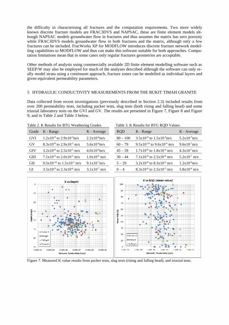
Data collected from recent investigations (previously described in Section 2.3) included results from over 200 permeability tests, including packer tests, slug tests (both rising and falling head) and some triaxial laboratory tests on the GVI and GV. The results are presented in Figure 7, Figure 8 and Figure 9; and in Table 2 and Table 3 below.
Table 2. K Results for BTG Weathering Grades. Table 3. K Results for BTG RQD Values.
Grade K - Range K - Average RQD K - Range K - Average
GVI 1.2x10⁻⁹ to 2.9x10⁻⁵m/s 2.2x10⁻⁶m/s 80 – 100 3.5x10⁻⁹ to 1.5x10⁻⁵m/s 5.2x10⁻⁷m/s
GV 8.3x10⁻⁸ to 2.9x10⁻⁵ m/s 5.6x10⁻⁶m/s 60 – 79 9.5x10⁻¹⁰ to 9.6x10⁻⁶ m/s 9.6x10⁻⁷m/s
GIV 3.2x10⁻⁸ to 2.5x10⁻⁵ m/s 4.0x10⁻⁶m/s 45 – 59 1.7x10⁻⁸ to 1.8x10⁻⁶ m/s 4.3x10⁻⁷m/s
GIII 7.1x10⁻⁹ to 2.0x10⁻⁵ m/s 1.0x10⁻⁶ m/s 30 – 44 7.1x10⁻⁹ to 2.5x10⁻⁶ m/s 5.2x10⁻⁷ m/s
GII 9.5x10⁻¹⁰ to 1.5x10⁻⁵ m/s 9.1x10⁻⁷m/s 5 – 29 3.2x10⁻⁸ to 8.3x10⁻⁶ m/s 1.2x10⁻⁶m/s
GI 3.5x10⁻⁹ to 2.3x10⁻⁶ m/s 3.1x10⁻⁷ m/s 0 – 4 8.3x10⁻⁸ to 2.5x10⁻⁵ m/s 5.8x10⁻⁶ m/s
Figure 7. Measured K value results from packer tests, slug tests (rising and falling head), and triaxial tests.
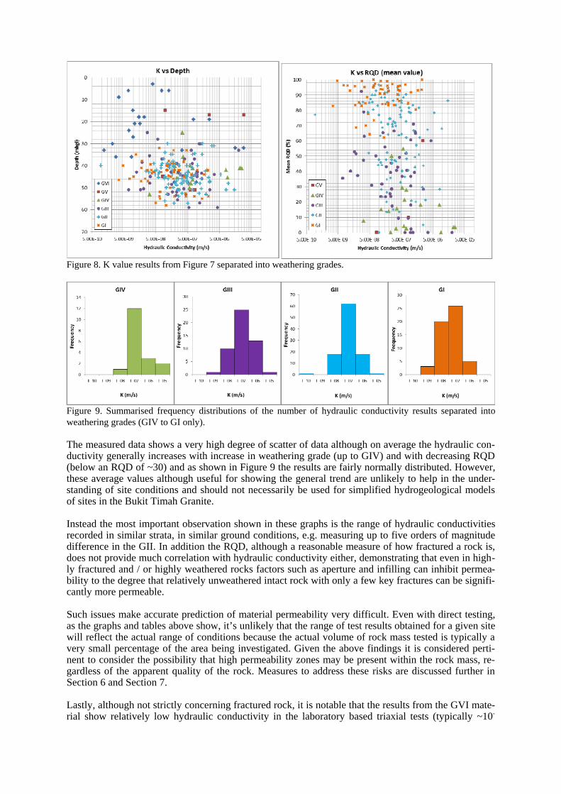
Figure 8. K value results from Figure 7 separated into weathering grades.
Figure 9. Summarised frequency distributions of the number of hydraulic conductivity results separated into weathering grades (GIV to GI only).
The measured data shows a very high degree of scatter of data although on average the hydraulic con-ductivity generally increases with increase in weathering grade (up to GIV) and with decreasing RQD (below an RQD of ~30) and as shown in Figure 9 the results are fairly normally distributed. However, these average values although useful for showing the general trend are unlikely to help in the under-standing of site conditions and should not necessarily be used for simplified hydrogeological models of sites in the Bukit Timah Granite.
Instead the most important observation shown in these graphs is the range of hydraulic conductivities recorded in similar strata, in similar ground conditions, e.g. measuring up to five orders of magnitude difference in the GII. In addition the RQD, although a reasonable measure of how fractured a rock is, does not provide much correlation with hydraulic conductivity either, demonstrating that even in high-ly fractured and / or highly weathered rocks factors such as aperture and infilling can inhibit permea-bility to the degree that relatively unweathered intact rock with only a few key fractures can be signifi-cantly more permeable.
Such issues make accurate prediction of material permeability very difficult. Even with direct testing, as the graphs and tables above show, it’s unlikely that the range of test results obtained for a given site will reflect the actual range of conditions because the actual volume of rock mass tested is typically a very small percentage of the area being investigated. Given the above findings it is considered perti-nent to consider the possibility that high permeability zones may be present within the rock mass, re-gardless of the apparent quality of the rock. Measures to address these risks are discussed further in Section 6 and Section 7.
Lastly, although not strictly concerning fractured rock, it is notable that the results from the GVI mate-rial show relatively low hydraulic conductivity in the laboratory based triaxial tests (typically ~10-
8m/s) but relatively high results from the field permeability slug tests (~10-6m/s). This probably indi-cates that the presence of relict fractures and fissures in the weathered soil mass still provide preferen-tial drainage pathways, as these features are unlikely to be picked up in small scale laboratory tests, indicating that field tests are more representative of the soil mass permeability on a macro scale.
6 APPLICATION OF GROUNDWATER FLOW MODELS IN BUKIT TIMAH GRANITE
6.1 Continuum Approach
An example of the continuum approach has been used based on actual data from a central location near Ang Mo Kio where a deep excavation was proposed. Application of this approach relies on the use of field collected hydraulic conductivity data from a number of boreholes, recharge wells and piezome-ters constructed at the site.
The boreholes indicated that the geology at this location comprised an approximately 7 m thick surface covering of fill underlain by the Kallang Formation (peaty clay) and GVI residual soil of the Bukit Timah Granite to depth varying from 16 to 30 mbgl. Underlying the GVI residual soil, granite rock of the Bukit Timah Granite is present showing decreasing weathering grade with depth from GIV to GII. The GIV is located between 20 and 32 mbgl and GIII to GII was located to a depth of around 50 mbgl at around which depth the boreholes were terminated. The GIII and GII was fairly variable and both were present at depth in the geological profile. It should be noted that other complexities such as an apparent dyke were located in this area but these are not discussed further as the purpose of this sec-tion is to illustrate a basic analytical continuum approach and highlight its benefits and limitations.
Sixteen packer tests were undertaken between the GIII and GII units, fourteen of which were predomi-nantly located in the GIII as this was the more fractured unit and more likely to be an issue during fu-ture excavation works. No packer tests specifically targeted the GIV, even though it was considered most likely to be most permeable, as it was possibly determined that any future excavation works would install a suitable earth retaining system through the fractured GIV thus preventing any ground-water ingress from this layer.
The range of hydraulic conductivity measurements from the packer tests intersecting the fractured GIII rock unit was: 1.29 x 10⁻⁸ and 6.38 x 10⁻⁷ m/s, and the average was 1.4 x 10⁻⁷ m/s. A majority of the sample sections had an RQD greater than 50% so was not considered to be highly fractured and as the variance of the hydraulic conductivity values about the mean was relatively low the GIII hydraulic conductivity may have been assumed to contain a statistically repeatable sample size. Based on these results it may be reasonable to a select the mean K value from the data range and derive average aqui-fer properties such as mean transmissivity which over ~15m vertical profile of GIII gives a total transmissivity of 2.1 x 10⁻⁶ m2/s.
This method does not take into consideration fracture groundwater flow, rather the fractured rock mass is treated as a singular unit and despite the relatively high number of hydraulic conductivity tests at this location there is no way to be certain that the representative elementary volume has been captured. It does, allow these basic parameters to be taken forward and used for more detailed analysis but any assessment must be mindful that, as was shown in Section 5, the potential variability may be very large and even taking the upper bound results from the on-site test data is unlikely to represent the most permeable zones in the site and the risk of these should be considered even if the general conditions are represented by the test results.
In addition it should be noted that calculations of storativity, the volume of water released from an aq-uifer under pumping conditions (another key aquifer property), cannot be calculated without the ob-servations of the radial distance of drawdown, as would be observed in monitoring wells during pump-ing tests.
6.2 Discrete Fracture Approach
A discrete, or discontinuum, analysis may be undertaken by assessing flow transmissivity along indi-vidual fractures. This method uses the cubic law described in Section 4.2 and assumes fractures are smooth, planar and continuous.
By studying televiewer results or observations from excavations it is feasible to estimate joint aperture and roughness values along with joint orientation. Details of infilling are difficult to derive from televiewers but coupled with discontinuity analysis from core samples estimates may be made. Details on persistence and joint connectivity are not accounted for and cannot be assessed directly by this method but by comparing results to packer tests approximate values may be provisionally assumed.
Using the cubic law method it can be seen that the transmissivity of a single joint of 1mm aperture has a transmissivity 1x10⁻³m2/s which means if a 1m thickness of aquifer had a single continuous 1mm joint running along its length then the effective hydraulic conductivity of that 1m thick section would be 1x10⁻³m/s which is particularly high and would be equivalent to the permeability of some gravels. However, as highlighted this analysis is based on idealized assumptions, described above. As such televiewer results were analysed in sections of boreholes where packer tests had previously been taken and results were compared to those derived from the cubic law.
An example is given where a packer test was undertaken over a 2m length at a depth of 45.5 to 47.5m in fractured GIII to GIV material. The packer result was relatively high with a K = 9.1x10⁻⁶m/s. The televiewer recorded 10 significant joints with apparent apertures of 0.25 to 2mm. Using the cubic law the cumulative transmissivity of the 10 joints in the 2m section was reported to be 2.1x10⁻²m2/s which divided by the length of section gives an effective hydraulic conductivity of 1.1x10⁻²m/s, more than three orders of magnitude greater than the packer result. However, by factoring infill into the joints the aperture is reduced and the permeability is likewise reduced. Sensitivity analysis was undertaken and it was demonstrated that by reducing the aperture to 10% of its measured width (allowing for the effects of significant infilling as well as the reduction in connectivity) the effective hydraulic conductivity is reduced to 1.1x10⁻⁵m/s, roughly in line with the packer result. Seven other tests gave similar results when apparent aperture was reduced to between 15% to 2% of its measured width demonstrating a significant correlation. Given the limited number of tests analysed the sample set is not considered suf-ficient to prove that correlation and other results may require much larger or smaller effective aperture percentage reductions. However, the method may prove to be useful in assessing critical areas.
Another observation from the above assessment is how large the potential hydraulic conductivity could be if the fractures were open and connected with limited infill. These conditions may occur lo-cally creating preferential flow channels which further wash out infill materials creating even larger flow rates and volumes. These conditions may be particularly prevalent along fracture / deformation zones associated with faults and along valley centres.
Analysis of general groundwater flow in this manner, by assessing individual fracture conditions, is however, likely to be impractical for many projects due to the time taken to undertake such an assess-ment, and as mentioned critical fracture parameters such as infill and connectivity cannot be assessed with sufficient accuracy to give accurate groundwater flow predictions. As such the method described may be better used to identify particularly large open fractures, as described above, and assess poten-tial worst credible groundwater flow volumes at critical locations.
6.3 Summary of Groundwater Flow Modelling Approaches in the Bukit Timah Granite
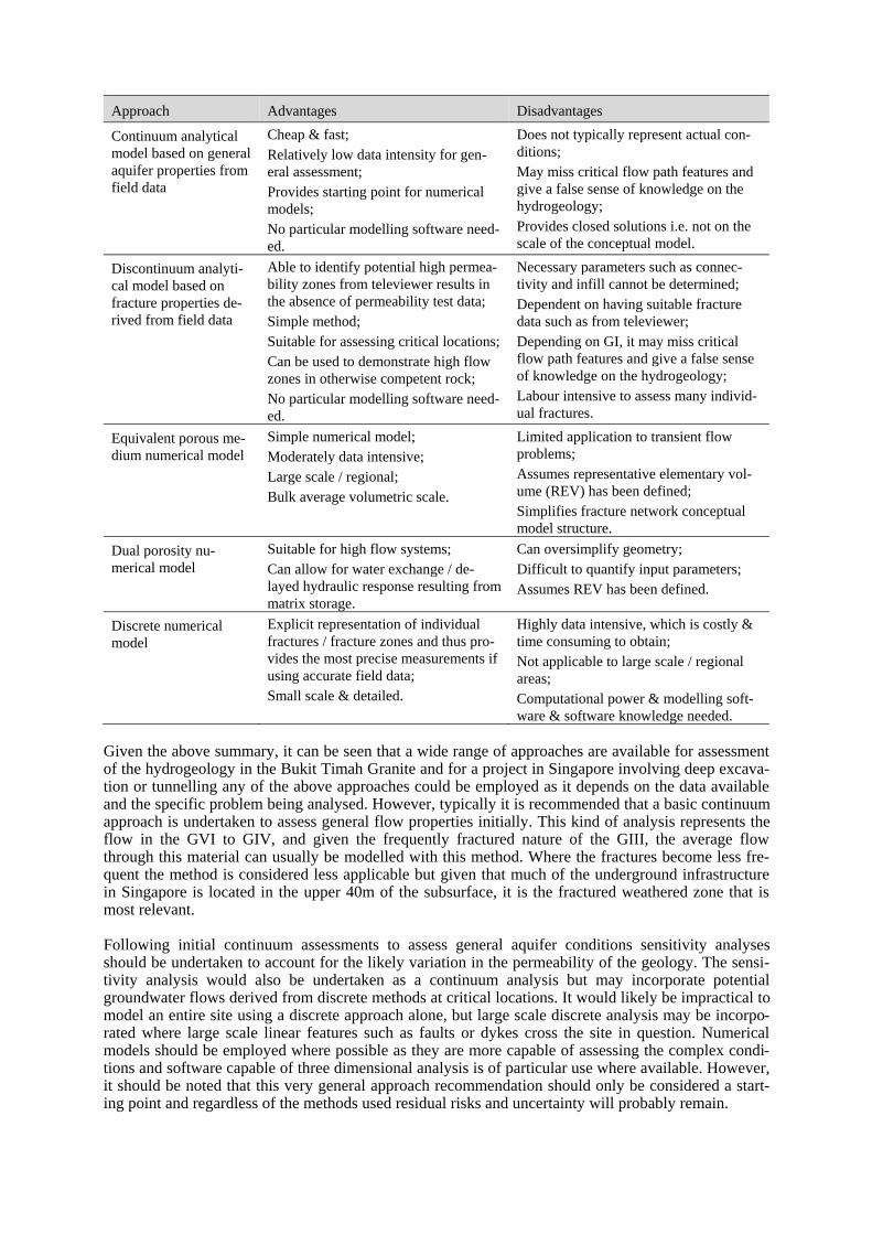
The different approaches used to quantify groundwater flow are critiqued for their practical suitability, minimum input data requirements and ability to quantify groundwater flow in Table 4. Note that nu-merical analyses have not been undertaken specifically as part of this study but it is important to un-derstand how the continuum and discrete approaches can feed into these and what the advantages and disadvantages of these are and hence these methods are also included in Table 4. Table 4. Advantages and disadvantages of the different groundwater flow modelling approaches
Approach Advantages Disadvantages
Continuum analytical model based on general aquifer properties from field data
Cheap & fast; Relatively low data intensity for gen-eral assessment; Provides starting point for numerical models; No particular modelling software need-ed.
Does not typically represent actual con-ditions; May miss critical flow path features and give a false sense of knowledge on the hydrogeology; Provides closed solutions i.e. not on the scale of the conceptual model.
Discontinuum analyti-cal model based on fracture properties de-rived from field data
Able to identify potential high permea-bility zones from televiewer results in the absence of permeability test data; Simple method; Suitable for assessing critical locations; Can be used to demonstrate high flow zones in otherwise competent rock; No particular modelling software need-ed.
Necessary parameters such as connec-tivity and infill cannot be determined; Dependent on having suitable fracture data such as from televiewer; Depending on GI, it may miss critical flow path features and give a false sense of knowledge on the hydrogeology; Labour intensive to assess many individ-ual fractures.
Equivalent porous me-dium numerical model
Simple numerical model; Moderately data intensive; Large scale / regional; Bulk average volumetric scale.
Limited application to transient flow problems; Assumes representative elementary vol-ume (REV) has been defined; Simplifies fracture network conceptual model structure.
Dual porosity nu-merical model
Suitable for high flow systems; Can allow for water exchange / de-layed hydraulic response resulting from matrix storage.
Can oversimplify geometry; Difficult to quantify input parameters; Assumes REV has been defined.
Discrete numerical model
Explicit representation of individual fractures / fracture zones and thus pro-vides the most precise measurements if using accurate field data; Small scale & detailed.
Highly data intensive, which is costly & time consuming to obtain; Not applicable to large scale / regional areas; Computational power & modelling soft-ware & software knowledge needed.
Given the above summary, it can be seen that a wide range of approaches are available for assessment of the hydrogeology in the Bukit Timah Granite and for a project in Singapore involving deep excava-tion or tunnelling any of the above approaches could be employed as it depends on the data available and the specific problem being analysed. However, typically it is recommended that a basic continuum approach is undertaken to assess general flow properties initially. This kind of analysis represents the flow in the GVI to GIV, and given the frequently fractured nature of the GIII, the average flow through this material can usually be modelled with this method. Where the fractures become less fre-quent the method is considered less applicable but given that much of the underground infrastructure in Singapore is located in the upper 40m of the subsurface, it is the fractured weathered zone that is most relevant.
Following initial continuum assessments to assess general aquifer conditions sensitivity analyses should be undertaken to account for the likely variation in the permeability of the geology. The sensi-tivity analysis would also be undertaken as a continuum analysis but may incorporate potential groundwater flows derived from discrete methods at critical locations. It would likely be impractical to model an entire site using a discrete approach alone, but large scale discrete analysis may be incorpo-rated where large scale linear features such as faults or dykes cross the site in question. Numerical models should be employed where possible as they are more capable of assessing the complex condi-tions and software capable of three dimensional analysis is of particular use where available. However, it should be noted that this very general approach recommendation should only be considered a start-ing point and regardless of the methods used residual risks and uncertainty will probably remain.
So it can be seen that a number of methods are available, all of which may be used to assess the hy-drogeology in the Bukit Timah Granite depending on the circumstances but it is always necessary that any assessment considers its limitations and records what risks remain because all the assessment ap-proaches described above will typically make significant assumptions and few are likely to represent the true hydrogeological conditions because the situation in the Bukit Timah Granite is generally too complex and geotechnical and hydrogeological investigations are generally not capable of assessing the all the parameters necessary to fully describe the true conditions.
In order to account for the uncertainty and risk described above, the flow analysis and modelling should always be accompanied by a sufficient hydrogeological assessment which has identified the po-tential risks and possible variation in anticipated conditions so that a sensitivity analysis can be under-taken and flow assessments can be re-done to check for potential worst credible situations. Considera-tions for hydrogeological assessments are further described in Section 7.
7 PROCEDURES FOR UNDERTAKING HYDROGEOLOGICAL INVESTIGATIONS AND ASSESSMENTS IN BUKIT TIMAH GRANITE
In order to gain a sufficient understanding of the hydrogeological setting and derive the appropriate parameters required so that groundwater flow can be modelled most accurately it is necessary to un-dertake a suitable hydrogeological assessment including a sufficient intrusive ground investigation. Too often geotechnical assessments and investigations neglect the potential hydrogeological risks and undertake a limited number of permeability tests which are often poorly targeted. Outlined below are some key considerations which should be included in any hydrogeological site assessment in the Bukit Timah Granite along with appropriate investigation methods which may be included with a geotech-nical investigation or may be undertaken separately as a standalone hydrogeological investigation.
Risks and uncertainty associated with the hydrogeological conditions are inherent in sites located in the Bukit Timah Granite so in order to mitigate this, a number of measures may be undertaken includ-ing consideration of geomorphological and hydrogeological setting; provision of sufficiently detailed and focussed hydrogeological investigation; interpretation of investigation data and recognition of its limits so potential uncertainty can be assessed and these conditions can be accounted for during sensi-tivity analyses and design of risk mitigation measures.
7.1 Hydrogeological Setting
Any site assessment should consider the geomorphological and hydrogeological setting. This should include assessment of the following:
General site location such as whether the site is site is in a valley or along a current or former drainage path along which groundwater is likely to flow continuously, or perhaps the site is on a hill from which groundwater will naturally flow away from, only recharging during pre-cipitation.
Presence of nearby water bodies , such as the sea, reservoirs, lakes or rivers must be consid-ered because these may be in hydraulic connectivity with the groundwater beneath the study area.
Potential presence of faults or dykes as these represent linear features with fracture connectivi-ty which often develop into preferential drainage paths.
Presence of other features of note such as springs, hot springs or boggy ground.
7.2 Hydrogeological Investigation – Basic Aims and Methods
Where intrusive ground investigation works are to be undertaken at the site, field works should be planned to specifically assess the hydrogeological conditions and provide suitable parameters for the various approaches to modelling groundwater flow.
The aims of the investigation will depend on the specific aims of the project but for almost all investi-gations for underground infrastructure, they should, as a minimum, aim to:
Allow creation of a geological and hydrogeological conceptual model so groundwater flow can be modelled in the individual units;
Assess hydraulic conductivity of each geological unit, ideally in different areas of the site, in order to assess permeability parameters and calculate groundwater flow volumes;
Assess the nature of fractures in the rock units so discrete fractures can be assessed for poten-tial permeability; and
Monitor groundwater levels from various horizons.
Ideally, the investigation should also aim to: Assess the general permeability properties of the site on a larger scale to see how groundwater
flows through the site as a whole rather than just measuring permeability in small zones; Derive additional aquifer parameters such as storativity to show the volume of effective pore
space and identify how the water table will respond in a drawdown event; Assess groundwater flow direction to understand the original flow through the site prior to
construction.
The field investigation program must be targeted to the objectives of the study and for the fractured rock mass, the investigation should concentrate on collecting groundwater information at major dis-continuities in rock masses, such as faults and zones of weaknesses / weathering where flow is ex-pected to be greatest.
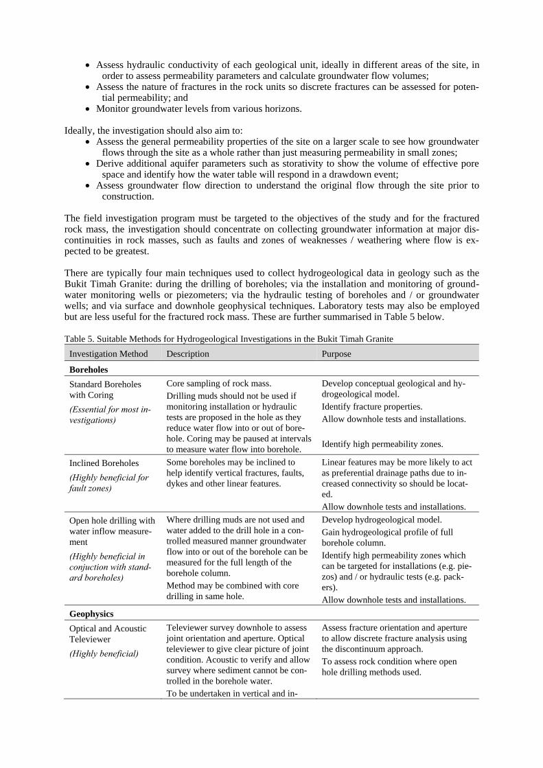
There are typically four main techniques used to collect hydrogeological data in geology such as the Bukit Timah Granite: during the drilling of boreholes; via the installation and monitoring of ground-water monitoring wells or piezometers; via the hydraulic testing of boreholes and / or groundwater wells; and via surface and downhole geophysical techniques. Laboratory tests may also be employed but are less useful for the fractured rock mass. These are further summarised in Table 5 below.
Table 5. Suitable Methods for Hydrogeological Investigations in the Bukit Timah Granite
Investigation Method Description Purpose
Boreholes
Standard Boreholes with Coring
(Essential for most in-vestigations)
Core sampling of rock mass. Drilling muds should not be used if monitoring installation or hydraulic tests are proposed in the hole as they reduce water flow into or out of bore-hole. Coring may be paused at intervals to measure water flow into borehole.
Develop conceptual geological and hy-drogeological model. Identify fracture properties. Allow downhole tests and installations.
Identify high permeability zones.
Inclined Boreholes
(Highly beneficial for fault zones)
Some boreholes may be inclined to help identify vertical fractures, faults, dykes and other linear features.
Linear features may be more likely to act as preferential drainage paths due to in-creased connectivity so should be locat-ed. Allow downhole tests and installations.
Open hole drilling with water inflow measure-ment
(Highly beneficial in conjuction with stand-ard boreholes)
Where drilling muds are not used and water added to the drill hole in a con-trolled measured manner groundwater flow into or out of the borehole can be measured for the full length of the borehole column. Method may be combined with core drilling in same hole.
Develop hydrogeological model. Gain hydrogeological profile of full borehole column. Identify high permeability zones which can be targeted for installations (e.g. pie-zos) and / or hydraulic tests (e.g. pack-ers). Allow downhole tests and installations.
Geophysics
Optical and Acoustic Televiewer
(Highly beneficial)
Televiewer survey downhole to assess joint orientation and aperture. Optical televiewer to give clear picture of joint condition. Acoustic to verify and allow survey where sediment cannot be con-trolled in the borehole water. To be undertaken in vertical and in-
Assess fracture orientation and aperture to allow discrete fracture analysis using the discontinuum approach. To assess rock condition where open hole drilling methods used.
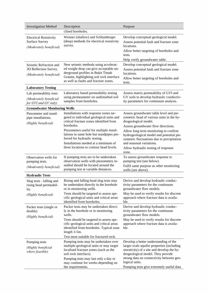
Investigation Method Description Purpose
clined boreholes.
Electrical Resistivity Surface Survey
(Moderately beneficial)
Wenner (shallow) and Schlumberger (deep) methods for electrical resistivity survey.
Develop conceptual geological model. Assess potential fault and fracture zone locations. Allow better targeting of boreholes and tests. Help verify groundwater table.
Seismic Refraction and 3D Reflection Survey.
(Moderately beneficial)
New seismic methods using accelerat-ed weight drop can give acceptable un-derground profiles in Bukit Timah Granite, highlighting soil rock interface as well as faults and fracture zones.
Develop conceptual geological model. Assess potential fault and fracture zone locations. Allow better targeting of boreholes and tests.
Laboratory Testing
Lab permeability tests
(Moderately beneficial for GVI and GV only)
Laboratory based permeability testing using permeameter on undisturbed soil samples from boreholes.
Assess matrix permeability of GVI and GV soils to develop hydraulic conductiv-ity parameters for continuum analysis.
Groundwater Monitoring Wells
Piezometer and stand-pipe installations.
(Highly beneficial)
Installations with response zones tar-geted to individual geological units and critical fracture zones identified from boreholes. Piezometers useful for multiple instal-lations in same hole but standpipes pre-ferred for hydraulic testing. Installations needed at a minimum of three locations to contour head levels.
Assess groundwater table level and pie-zometric head of various units in the hy-drogeological model. Assess groundwater flow directions. Allow long term monitoring to confirm hydrogeological model and potential pie-zometric fluctuations due to precipitation and seasonal variations. Allow hydraulic testing of response zone.
Observation wells for pumping tests.
(Moderately beneficial)
If pumping tests are to be undertaken observation wells with piezometers in-stalled should be located around the pumping test at variable distances.
To assess groundwater response to pumping test (see below). Fulfil same purpose as other monitoring wells (see above).
Hydraulic Tests
Slug tests - falling and rising head permeabil-ity.
(Highly beneficial)
Rising and falling head slug tests may be undertaken directly in the borehole or in monitoring wells. Tests should be targeted to assess spe-cific geological units and critical areas identified from boreholes.
Derive and develop hydraulic conduc-tivity parameters for the continuum groundwater flow models. May be used to verify results for discrete approach where fracture data is availa-ble.
Packer tests (single or double)
(Highly beneficial)
Packer tests may be undertaken direct-ly in the borehole or in monitoring wells. Tests should be targeted to assess spe-cific geological units and critical areas identified from boreholes. Typical zone length 3-5m. Test most suitable for fractured rock.
Derive and develop hydraulic conduc-tivity parameters for the continuum groundwater flow models. May be used to verify results for discrete approach where fracture data is availa-ble.
Pumping tests
(Highly beneficial where feasible)
Pumping tests may be undertaken over multiple geological units or may target localised fracture zones (such as the soil rock interface). Pumping tests may last only a day or may continue for weeks depending on the requirements.
Develop a better understanding of the larger scale aquifer properties (including storativity) of a site and develop the hy-drogeological model. They provide strong data on connectivity between geo-logical units. Pumping tests give extremely useful data
Investigation Method Description Purpose
but may not be feasible for small scale investigations.
Tracer tests
(Moderately beneficial where feasible)
Tracer dyes or other markers may be introduced into up gradient wells and the concentration may be measured in down gradient wells.
Develop a better understanding of the hydrogeological model. Provide infor-mation on connectivity between geologi-cal units as well as hydraulic conductivi-ty. May not be feasible for small scale investigations.
Other methods such as Downhole Density, Neutron and Resistivity Logs may also be used to assess physical properties such as porosity, moisture content, fracturing but this is generally not necessary in shallow boreholes in the Bukit Timah Granite.
7.3 Interpretation of Data and Consideration of Risks and Uncertainty
By undertaking an assessment and investigation as outlined above, suitable high quality data hydroge-ological should be available to allow accurate and honest derivation of aquifer parameters to be incor-porated into both continuum and discrete flow models which can then be used in numerical models. However, even with a well-planned hydrogeological assessment and detailed investigation uncertainty will remain due to the extreme levels of hydrogeological variability in the Bukit Timah Granite, as dis-cussed in Section 5 and Section 6. As such interpretation of data and development of the hydrogeolog-ical model should consider potential probabilities of high permeability zones and large groundwater flow volumes. Ideally various models should be created and sensitivity analyses performed on the aq-uifer parameters to assess the potential impacts. Sometimes this level of analysis will not be possible but in all cases risk assessments should be undertaken and mitigation measures considered if the hy-drogeological conditions are worse than anticipated.
8 CONCLUSIONS
The shallow (<100m) weathered units of the Bukit Timah Granite forms a multi-layered variable geol-ogy which results in a highly complex and variable hydrogeological regime. Groundwater flow in the Bukit Timah Granite rock mass is typically via secondary flow i.e. concentrated along the intercon-nected discontinuities in the rock and each layer or zone exhibit its own hydrogeological parameters.
On average, the hydraulic conductivity increases with increased fracturing and weathering but these parameters do not correlate consistently due to less easily quantifiable parameters such as fracture in-fill and connectivity having a major impact. As such very large degrees of variation are exhibited, with observations from recent investigations showing hydraulic conductivity results with five orders of magnitude difference in the GII unit alone (10-10m/s to 10-5m/s). As a result factors other than weather-ing grade and number of fractures must be considered to accurately model the groundwater flow and assess the potential variation risks.
Two methods to quantify groundwater flow have been provided: the continuum and discrete approach. Use of the continuum approach ignores the details of individual fractures and the unit is treated as po-rous continuum. The discrete method explicitly defines individual fractures and extrapolates fracture flow. These methods can be applied analytically or via numerical models; analytical approaches pro-vide quick, cheap and localised assessments of groundwater flow while numerical approaches are broader, but require greater data input and software.
For both approaches the flow modelling should be undertaken as part of a comprehensive hydrogeo-logical assessment which considers the site setting and should include an intrusive investigation to produce field data of sufficient quality and quantity to develop the hydrogeological model.
The type of field data required depends on the approach utilised but best practice is to investigate for both approaches and tests should be targeted to gather the most useful data from each unit and from critical areas such as faults and fracture zones where risks may be greatest.
In conclusion it is recommended that any hydrogeological assessment considers both methods of anal-ysis and where possible performs numerical modelling that includes sensitivity analysis and assess-ment of potentially worst credible conditions because uncertainty and hydrogeological risk are inher-ent in the Bukit Timah Granite.
REFERENCES
Cook, P. G., 2003. A Guide to Regional Groundwater Flow in Fractured Rock Aquifers, CSIRO Australia, CM Digital, South Australia
Domenico, P. A. & Schwartz, F. W., 1990. Physical and Chemical Hydrogeology, Second Edition. New York. John Wiley & Sons, Inc.
Fetter, C. W., 2014. Applied Hydrogeology, Fourth Edition. Pearson Education Limited, Essex.
Gudmundsson, A., 2011. Rock Fractures in Geological Processes. Cambridge University Press.
Li, S-J. & Liu, Y-X., 2007. Permeability estimation of jointed rock mass using fractured network model. Journal of Physics: Conference Series 96 (2008) 012131.
Pfeifer, D., 1975. The hydrogeological map of the Island of Singapore 1:100,000 (explanatory notes). Das Geol-ogische Jahrbuch 3, 3-14.
Phyo, W., Mun Cheong, Y., Khin, K., Han, B.H., & Zaw, H. 2014 Geological rock face mapping and kinematics for drill and blast excavation. Awaiting final publication.
Romm, E., S. 1966. Flow Characteristics of Fractured Rocks (in Russia). Nedra, Moscow
Samaniego, J., A. & Priest, S., D. 1984. The prediction of water flow through discontinuity networks into under-ground excavations. Proceedings of the ISRM Symposium of Design and Performance of Underground Ex-cavations. British Geotechnical Society, London. Pp. 157-164
Shapiro, M., A. & Andersson, J. 1983 Steady State Fluid Response in Fractured Rock: a boundary element solu-tion for a couple discrete fracture continuum mode. Water Resources 19 No 4, 959-969
Singal, B.B.S. & Gupta, R.P., 2010. Applied Hydrogeology of Fractured Rocks, Second Edition. Springer.
Snow, D., T. 1968. Rock Fracture Spacings, Openings and Porosities. J. Soil Mech., Found. Div., Proc. Am. Soc. Civil Engrs., v.94, p. 73-91
Van Golf-Racht. T., D. 1982 Fundamentals of Fractured Reservoir Engineering. Elsevier, New York
Wei, Z., Q. & Hudson, J., A. 1993 A Coupled Discrete – Continuum Approach for Modelling of Water Flow in Jointed Rocks. Geotechnique 43, No. 1, 21-36
Zhao, J. 1998. Rock mass hydraulic conductivity of the Bukit Timah Granite, Singapore. Engineering Geology 50: 211-216
Zhao, J., Broms, B., B., Zhou, Y., & Chao, V. 1994. A Study if the Weathering of the Bukit Timah Granite Part B: field and laboratory investigations. Bulletin of the International Association of Engineering Geology, Paris No. 50, October
Zhou, Y., 2001. Engineering Geology and Rock Mass Properties of the Bukit Timah Granite. Proceedings of the Underground Singapore Conference 2001. Pp. 308-314.


![[SUPP1 - 20] BT/NEWS/PAGES 23/02/12 · Ang Mo Kio Bishan Bukit Panjang Bukit Batok Bukit Timah Jurong West Tuas Ghim Moh Marina South Marina East Kallang ... Frasers](https://img.pdfslide.net/doc/110x75/5f0be7107e708231d432c864/supp1-20-btnewspages-230212-ang-mo-kio-bishan-bukit-panjang-bukit-batok.jpg)


![[20대연구소] 주간뉴스클리핑(20140804 0810)](https://img.pdfslide.net/doc/110x75/55904caa1a28ab330e8b45ca/20-20140804-0810.jpg)