Embed Size (px)
Citation preview

Operator's Manual
2028451-182 Revision B
GE Healthcare
MAC™ 1600 ECG Analysis System
Software Version 1.0

T-2 MAC™ 1600 2028451-182B25 April 2008
NOTEThis manual applies MAC™ 1600 software version 1.0.
This product complies with regulatory requirements of the following European Directive 93/42/EEC concerning medical devices.
Archivist, CardioSoft, CASE, Hookup Advisor, MAC, Mactrode, Multi-Link, MUSE, SilverTRACE, and 12SL are trademarks owned by General Electric Company. All other marks are not owned by GE and are instead owned by their respective owners.
©2008 General Electric Company. All rights reserved.
2028451-182B MAC™ 1600 i
Contents1 Introduction
Manual Information . . . . . . . . . . . . . . . . . . . . . . . . . . . . . . . . . . . . . . . . . . . . . . . . . . . 1-2Purpose . . . . . . . . . . . . . . . . . . . . . . . . . . . . . . . . . . . . . . . . . . . . . . . . . . . . . . . . .1-2Intended Audience . . . . . . . . . . . . . . . . . . . . . . . . . . . . . . . . . . . . . . . . . . . . . . . . .1-2Revision History . . . . . . . . . . . . . . . . . . . . . . . . . . . . . . . . . . . . . . . . . . . . . . . . . . .1-2Conventions . . . . . . . . . . . . . . . . . . . . . . . . . . . . . . . . . . . . . . . . . . . . . . . . . . . . . .1-2Product References . . . . . . . . . . . . . . . . . . . . . . . . . . . . . . . . . . . . . . . . . . . . . . . .1-3Illustrations and Names . . . . . . . . . . . . . . . . . . . . . . . . . . . . . . . . . . . . . . . . . . . . .1-3
Safety Information. . . . . . . . . . . . . . . . . . . . . . . . . . . . . . . . . . . . . . . . . . . . . . . . . . . . 1-3Safety Messages. . . . . . . . . . . . . . . . . . . . . . . . . . . . . . . . . . . . . . . . . . . . . . . . . . 1-3Classification . . . . . . . . . . . . . . . . . . . . . . . . . . . . . . . . . . . . . . . . . . . . . . . . . . . . .1-9Underwriters Laboratories, Inc. . . . . . . . . . . . . . . . . . . . . . . . . . . . . . . . . . . . . . . .1-9Biocompatibility . . . . . . . . . . . . . . . . . . . . . . . . . . . . . . . . . . . . . . . . . . . . . . . . . .1-10Legal Notice . . . . . . . . . . . . . . . . . . . . . . . . . . . . . . . . . . . . . . . . . . . . . . . . . . . . .1-10Responsibility of the Manufacturer . . . . . . . . . . . . . . . . . . . . . . . . . . . . . . . . . . . .1-10
General Information . . . . . . . . . . . . . . . . . . . . . . . . . . . . . . . . . . . . . . . . . . . . . . . . . 1-10Indications of Use . . . . . . . . . . . . . . . . . . . . . . . . . . . . . . . . . . . . . . . . . . . . . . . . .1-10Contraindications . . . . . . . . . . . . . . . . . . . . . . . . . . . . . . . . . . . . . . . . . . . . . . . . .1-11Recording ECGs During Defibrillation . . . . . . . . . . . . . . . . . . . . . . . . . . . . . . . . .1-11Accuracy Of the Input Signal Reproduction . . . . . . . . . . . . . . . . . . . . . . . . . . . . .1-12Modulating Effects in Digital Systems . . . . . . . . . . . . . . . . . . . . . . . . . . . . . . . . .1-12Installation and Connection . . . . . . . . . . . . . . . . . . . . . . . . . . . . . . . . . . . . . . . . .1-12Parts and Accessories . . . . . . . . . . . . . . . . . . . . . . . . . . . . . . . . . . . . . . . . . . . . .1-12Equipment Symbols . . . . . . . . . . . . . . . . . . . . . . . . . . . . . . . . . . . . . . . . . . . . . . .1-13
Service Information. . . . . . . . . . . . . . . . . . . . . . . . . . . . . . . . . . . . . . . . . . . . . . . . . . 1-15Service Requirements . . . . . . . . . . . . . . . . . . . . . . . . . . . . . . . . . . . . . . . . . . . . .1-15Equipment Identification . . . . . . . . . . . . . . . . . . . . . . . . . . . . . . . . . . . . . . . . . . . .1-15
2 Equipment Overview
Equipment Description. . . . . . . . . . . . . . . . . . . . . . . . . . . . . . . . . . . . . . . . . . . . . . . . 2-2Front View . . . . . . . . . . . . . . . . . . . . . . . . . . . . . . . . . . . . . . . . . . . . . . . . . . . . . . .2-2Side View . . . . . . . . . . . . . . . . . . . . . . . . . . . . . . . . . . . . . . . . . . . . . . . . . . . . . . . .2-3Back View . . . . . . . . . . . . . . . . . . . . . . . . . . . . . . . . . . . . . . . . . . . . . . . . . . . . . . . .2-3Keyboard Layout . . . . . . . . . . . . . . . . . . . . . . . . . . . . . . . . . . . . . . . . . . . . . . . . . .2-4Acquisition Modules . . . . . . . . . . . . . . . . . . . . . . . . . . . . . . . . . . . . . . . . . . . . . . . .2-6Leadwire Adapters . . . . . . . . . . . . . . . . . . . . . . . . . . . . . . . . . . . . . . . . . . . . . . . . .2-7
Setting Up the Equipment . . . . . . . . . . . . . . . . . . . . . . . . . . . . . . . . . . . . . . . . . . . . . 2-7Inserting the Battery . . . . . . . . . . . . . . . . . . . . . . . . . . . . . . . . . . . . . . . . . . . . . . . .2-8Connecting the AC Power Adapter . . . . . . . . . . . . . . . . . . . . . . . . . . . . . . . . . . . .2-8Connecting Leadwires . . . . . . . . . . . . . . . . . . . . . . . . . . . . . . . . . . . . . . . . . . . . . .2-9
ii MAC™ 1600 2028451-182B
Inserting Paper . . . . . . . . . . . . . . . . . . . . . . . . . . . . . . . . . . . . . . . . . . . . . . . . . . . .2-9Connecting the Barcode Reader . . . . . . . . . . . . . . . . . . . . . . . . . . . . . . . . . . . . .2-10Connecting the Optional Internal Modem . . . . . . . . . . . . . . . . . . . . . . . . . . . . . . .2-10Connecting to an External Modem . . . . . . . . . . . . . . . . . . . . . . . . . . . . . . . . . . . .2-10Connecting to a LAN . . . . . . . . . . . . . . . . . . . . . . . . . . . . . . . . . . . . . . . . . . . . . .2-10Connecting External Devices (Stress Option) . . . . . . . . . . . . . . . . . . . . . . . . . . .2-10Turning on the System . . . . . . . . . . . . . . . . . . . . . . . . . . . . . . . . . . . . . . . . . . . . .2-11Configuring the Device . . . . . . . . . . . . . . . . . . . . . . . . . . . . . . . . . . . . . . . . . . . . .2-11Testing the Device . . . . . . . . . . . . . . . . . . . . . . . . . . . . . . . . . . . . . . . . . . . . . . . .2-11
System Description. . . . . . . . . . . . . . . . . . . . . . . . . . . . . . . . . . . . . . . . . . . . . . . . . . 2-12Start Up Screen . . . . . . . . . . . . . . . . . . . . . . . . . . . . . . . . . . . . . . . . . . . . . . . . . .2-12Using the MAC 1600 Keyboard. . . . . . . . . . . . . . . . . . . . . . . . . . . . . . . . . . . . . . 2-12
3 Preparing the Patient
Prepare the Patient’s Skin . . . . . . . . . . . . . . . . . . . . . . . . . . . . . . . . . . . . . . . . . . . . . 3-2
Applying the Electrodes . . . . . . . . . . . . . . . . . . . . . . . . . . . . . . . . . . . . . . . . . . . . . . . 3-3Resting ECG Electrodes . . . . . . . . . . . . . . . . . . . . . . . . . . . . . . . . . . . . . . . . . . . .3-4Stress ECG Electrodes . . . . . . . . . . . . . . . . . . . . . . . . . . . . . . . . . . . . . . . . . . . . .3-6
4 Entering Patient Information
Entering Patient Information Manually . . . . . . . . . . . . . . . . . . . . . . . . . . . . . . . . . . . 4-2
Entering Patient Information with a Barcode Reader . . . . . . . . . . . . . . . . . . . . . . . 4-3
5 Recording a Resting ECG
Introduction . . . . . . . . . . . . . . . . . . . . . . . . . . . . . . . . . . . . . . . . . . . . . . . . . . . . . . . . 5-2
Resting ECGs . . . . . . . . . . . . . . . . . . . . . . . . . . . . . . . . . . . . . . . . . . . . . . . . . . . . . . . 5-3Recording a Resting ECG . . . . . . . . . . . . . . . . . . . . . . . . . . . . . . . . . . . . . . . . . . .5-3ECG Options . . . . . . . . . . . . . . . . . . . . . . . . . . . . . . . . . . . . . . . . . . . . . . . . . . . . .5-4Post-Acquisition Options . . . . . . . . . . . . . . . . . . . . . . . . . . . . . . . . . . . . . . . . . . . .5-6
Generating a Rhythm Report (Manual Recording) . . . . . . . . . . . . . . . . . . . . . . . . . 5-7
ECG Reanalysis. . . . . . . . . . . . . . . . . . . . . . . . . . . . . . . . . . . . . . . . . . . . . . . . . . . . . . 5-8Reanalyzing an ECG . . . . . . . . . . . . . . . . . . . . . . . . . . . . . . . . . . . . . . . . . . . . . . .5-8Reanalysis Layout . . . . . . . . . . . . . . . . . . . . . . . . . . . . . . . . . . . . . . . . . . . . . . . . .5-9Reanalysis Options . . . . . . . . . . . . . . . . . . . . . . . . . . . . . . . . . . . . . . . . . . . . . . .5-10
Hookup Advisor Module . . . . . . . . . . . . . . . . . . . . . . . . . . . . . . . . . . . . . . . . . . . . . 5-12
Special Considerations . . . . . . . . . . . . . . . . . . . . . . . . . . . . . . . . . . . . . . . . . . . . . . 5-12Recording ECGs of Pacemaker Patients . . . . . . . . . . . . . . . . . . . . . . . . . . . . . . .5-13Recording ECGs during Defibrillation . . . . . . . . . . . . . . . . . . . . . . . . . . . . . . . . . .5-13
2028451-182B MAC™ 1600 iii
6 Arrhythmia Mode Recording
Introduction . . . . . . . . . . . . . . . . . . . . . . . . . . . . . . . . . . . . . . . . . . . . . . . . . . . . . . . . 6-2
Arrhythmia Mode. . . . . . . . . . . . . . . . . . . . . . . . . . . . . . . . . . . . . . . . . . . . . . . . . . . . . 6-2Printing an Arrhythmia Report . . . . . . . . . . . . . . . . . . . . . . . . . . . . . . . . . . . . . . . .6-2Arrhythmia Options . . . . . . . . . . . . . . . . . . . . . . . . . . . . . . . . . . . . . . . . . . . . . . . . .6-3Printing Options . . . . . . . . . . . . . . . . . . . . . . . . . . . . . . . . . . . . . . . . . . . . . . . . . . .6-5
Arrhythmia Codes . . . . . . . . . . . . . . . . . . . . . . . . . . . . . . . . . . . . . . . . . . . . . . . . . . . 6-5
7 Stress Testing
Introduction . . . . . . . . . . . . . . . . . . . . . . . . . . . . . . . . . . . . . . . . . . . . . . . . . . . . . . . . 7-2
Stress Mode Interface. . . . . . . . . . . . . . . . . . . . . . . . . . . . . . . . . . . . . . . . . . . . . . . . . 7-3Stress Test Information Bar . . . . . . . . . . . . . . . . . . . . . . . . . . . . . . . . . . . . . . . . . .7-3Stress Test Keys . . . . . . . . . . . . . . . . . . . . . . . . . . . . . . . . . . . . . . . . . . . . . . . . . .7-5Stress Options . . . . . . . . . . . . . . . . . . . . . . . . . . . . . . . . . . . . . . . . . . . . . . . . . . . .7-6
Conducting Stress Tests . . . . . . . . . . . . . . . . . . . . . . . . . . . . . . . . . . . . . . . . . . . . . . 7-8Conducting a Stress Test with a Treadmill or Ergometer . . . . . . . . . . . . . . . . . . . .7-8Conducting a Stress Test with a Master’s Step Device . . . . . . . . . . . . . . . . . . . .7-11
8 Managing Internal Storage
Introduction . . . . . . . . . . . . . . . . . . . . . . . . . . . . . . . . . . . . . . . . . . . . . . . . . . . . . . . . 8-2
Importing Records . . . . . . . . . . . . . . . . . . . . . . . . . . . . . . . . . . . . . . . . . . . . . . . . . . . 8-3
Printing the File Manager Directory . . . . . . . . . . . . . . . . . . . . . . . . . . . . . . . . . . . . . 8-4
Finding Records . . . . . . . . . . . . . . . . . . . . . . . . . . . . . . . . . . . . . . . . . . . . . . . . . . . . . 8-4
Editing Patient Data . . . . . . . . . . . . . . . . . . . . . . . . . . . . . . . . . . . . . . . . . . . . . . . . . . 8-5
Deleting Records . . . . . . . . . . . . . . . . . . . . . . . . . . . . . . . . . . . . . . . . . . . . . . . . . . . . 8-6
Printing Records . . . . . . . . . . . . . . . . . . . . . . . . . . . . . . . . . . . . . . . . . . . . . . . . . . . . 8-7
Transmitting Records . . . . . . . . . . . . . . . . . . . . . . . . . . . . . . . . . . . . . . . . . . . . . . . . 8-7
Exporting Records . . . . . . . . . . . . . . . . . . . . . . . . . . . . . . . . . . . . . . . . . . . . . . . . . . . 8-8
9 System Configuration
Introduction . . . . . . . . . . . . . . . . . . . . . . . . . . . . . . . . . . . . . . . . . . . . . . . . . . . . . . . . 9-2
Setup Functions . . . . . . . . . . . . . . . . . . . . . . . . . . . . . . . . . . . . . . . . . . . . . . . . . . . . . 9-2
iv MAC™ 1600 2028451-182B
Basic Setup . . . . . . . . . . . . . . . . . . . . . . . . . . . . . . . . . . . . . . . . . . . . . . . . . . . . . .9-2Resting ECG Setup . . . . . . . . . . . . . . . . . . . . . . . . . . . . . . . . . . . . . . . . . . . . . . . .9-6Arrhythmia Setup . . . . . . . . . . . . . . . . . . . . . . . . . . . . . . . . . . . . . . . . . . . . . . . . .9-12Stress ECG Setup . . . . . . . . . . . . . . . . . . . . . . . . . . . . . . . . . . . . . . . . . . . . . . . . 9-13Communication Setup . . . . . . . . . . . . . . . . . . . . . . . . . . . . . . . . . . . . . . . . . . . . .9-19Country Setup . . . . . . . . . . . . . . . . . . . . . . . . . . . . . . . . . . . . . . . . . . . . . . . . . . .9-23Patient Setup . . . . . . . . . . . . . . . . . . . . . . . . . . . . . . . . . . . . . . . . . . . . . . . . . . . .9-24User Setup . . . . . . . . . . . . . . . . . . . . . . . . . . . . . . . . . . . . . . . . . . . . . . . . . . . . . .9-27Options Setup . . . . . . . . . . . . . . . . . . . . . . . . . . . . . . . . . . . . . . . . . . . . . . . . . . . .9-29Service Setup . . . . . . . . . . . . . . . . . . . . . . . . . . . . . . . . . . . . . . . . . . . . . . . . . . . .9-30Date/Time Setup . . . . . . . . . . . . . . . . . . . . . . . . . . . . . . . . . . . . . . . . . . . . . . . . .9-31
Setup Utilities . . . . . . . . . . . . . . . . . . . . . . . . . . . . . . . . . . . . . . . . . . . . . . . . . . . . . . 9-31Print Setup Report . . . . . . . . . . . . . . . . . . . . . . . . . . . . . . . . . . . . . . . . . . . . . . . .9-31Select Setup . . . . . . . . . . . . . . . . . . . . . . . . . . . . . . . . . . . . . . . . . . . . . . . . . . . . .9-32Export Setup . . . . . . . . . . . . . . . . . . . . . . . . . . . . . . . . . . . . . . . . . . . . . . . . . . . . .9-33Import Setup . . . . . . . . . . . . . . . . . . . . . . . . . . . . . . . . . . . . . . . . . . . . . . . . . . . . .9-34Exporting Audit Trail . . . . . . . . . . . . . . . . . . . . . . . . . . . . . . . . . . . . . . . . . . . . . . .9-34
10 Maintenance
Introduction . . . . . . . . . . . . . . . . . . . . . . . . . . . . . . . . . . . . . . . . . . . . . . . . . . . . . . . 10-2
MAC 1600 Maintenance . . . . . . . . . . . . . . . . . . . . . . . . . . . . . . . . . . . . . . . . . . . . . . 10-2Inspecting the Equipment . . . . . . . . . . . . . . . . . . . . . . . . . . . . . . . . . . . . . . . . . . .10-3Cleaning the Device . . . . . . . . . . . . . . . . . . . . . . . . . . . . . . . . . . . . . . . . . . . . . . 10-3
Cable and Leadwire Maintenance . . . . . . . . . . . . . . . . . . . . . . . . . . . . . . . . . . . . . . 10-4Sanitizing Cables and Leadwires . . . . . . . . . . . . . . . . . . . . . . . . . . . . . . . . . . . . 10-4Storing Cables and Leadwires . . . . . . . . . . . . . . . . . . . . . . . . . . . . . . . . . . . . . . .10-7Replacing Leadwire Adapters . . . . . . . . . . . . . . . . . . . . . . . . . . . . . . . . . . . . . . .10-7
Paper Maintenance . . . . . . . . . . . . . . . . . . . . . . . . . . . . . . . . . . . . . . . . . . . . . . . . . . 10-8Replacing Paper . . . . . . . . . . . . . . . . . . . . . . . . . . . . . . . . . . . . . . . . . . . . . . . . . .10-8Adjusting the Paper Tray for Paper Size . . . . . . . . . . . . . . . . . . . . . . . . . . . . . . .10-9Storing Thermal Paper . . . . . . . . . . . . . . . . . . . . . . . . . . . . . . . . . . . . . . . . . . . .10-10
Battery Maintenance . . . . . . . . . . . . . . . . . . . . . . . . . . . . . . . . . . . . . . . . . . . . . . . . 10-11Battery Safety . . . . . . . . . . . . . . . . . . . . . . . . . . . . . . . . . . . . . . . . . . . . . . . . . . .10-12Replacing the Battery . . . . . . . . . . . . . . . . . . . . . . . . . . . . . . . . . . . . . . . . . . . . .10-12Conditioning the MAC 1600 Battery Pack . . . . . . . . . . . . . . . . . . . . . . . . . . . . .10-13
Supplies and Accessories . . . . . . . . . . . . . . . . . . . . . . . . . . . . . . . . . . . . . . . . . . . 10-14
A Troubleshooting
General Troubleshooting Tips . . . . . . . . . . . . . . . . . . . . . . . . . . . . . . . . . . . . . . . . . A-2
Equipment Problems . . . . . . . . . . . . . . . . . . . . . . . . . . . . . . . . . . . . . . . . . . . . . . . . . A-2System Will Not Power Up . . . . . . . . . . . . . . . . . . . . . . . . . . . . . . . . . . . . . . . . . . A-3
2028451-182B MAC™ 1600 v
ECG Data Contains Noise . . . . . . . . . . . . . . . . . . . . . . . . . . . . . . . . . . . . . . . . . . A-3ACI-TIPI Statement is Not Included on Report . . . . . . . . . . . . . . . . . . . . . . . . . . . A-4No BP Readings from Ergoline 900 Ergometer . . . . . . . . . . . . . . . . . . . . . . . . . . A-4External Device Does Not Move . . . . . . . . . . . . . . . . . . . . . . . . . . . . . . . . . . . . . A-4Paper Jams . . . . . . . . . . . . . . . . . . . . . . . . . . . . . . . . . . . . . . . . . . . . . . . . . . . . . A-5SD Card Not Present . . . . . . . . . . . . . . . . . . . . . . . . . . . . . . . . . . . . . . . . . . . . . . A-5Cannot Import or Transmit Records Via Modem . . . . . . . . . . . . . . . . . . . . . . . . . A-6Cannot Export to Shared Directories . . . . . . . . . . . . . . . . . . . . . . . . . . . . . . . . . . A-6
System Errors . . . . . . . . . . . . . . . . . . . . . . . . . . . . . . . . . . . . . . . . . . . . . . . . . . . . . . . A-7
B Creating Barcodes
Introduction . . . . . . . . . . . . . . . . . . . . . . . . . . . . . . . . . . . . . . . . . . . . . . . . . . . . . . . . B-2
Setting up the Patient Data Scheme . . . . . . . . . . . . . . . . . . . . . . . . . . . . . . . . . . . . . B-2
Configuring the Barcode Reader. . . . . . . . . . . . . . . . . . . . . . . . . . . . . . . . . . . . . . . . B-3Configuring the Barcode Reader Manually . . . . . . . . . . . . . . . . . . . . . . . . . . . . . B-3Configuring the Barcode Reader Automatically . . . . . . . . . . . . . . . . . . . . . . . . . . B-4
Index

vi MAC™ 1600 2028451-182B

2028451-182B MAC™ 1600 1-1
1 Introduction
1-2 MAC™ 1600 2028451-182B
Introduction
Manual Information
PurposeThis manual describes the safe and effective operation of the MAC™ 1600 .
Intended AudienceThis manual is written for clinical professionals who use, maintain, and/or troubleshoot the MAC™ 1600 . Clinical professionals are expected to have a working knowledge of appropriate medical procedures, practices, and terminology used in the treatment of patients.
Revision HistoryThe document part number and revision appear at the bottom of each page. The revision identifies the document’s update level.
ConventionsThe following conventions are used throughout this manual.
Revision History, PN 2028451-182
Revision Date Comment
A 29 February 2008 Initial release of document.
B 25 April 2008 Corrected the duration of the battery’s normal operation from 4 hours to 3.
Bold Indicates keys on the keyboard, text to be entered, or hardware items such as buttons or switches on the equipment.
Italics Indicates software terms that identify menu items, buttons, or options in various windows.
Ctrl + Esc Indicates a keyboard operation. A (+) sign between the names of two keys indicates that you must press and hold the first key while pressing the second key once.
For example, “Press Ctrl + Esc” means to press and hold down the Ctrl key while pressing the Esc key.
Enter Indicates you must press the “Enter” or “Return” key on the keyboard. Do not type “enter”.
Introduction
2028451-182B MAC™ 1600 1-3
Product ReferencesThe name of the product described in this manual is MAC 1600 ECG Analysis System. It will be referred to as “the system” or “the device” throughout this document.
Illustrations and NamesAll illustrations in this manual are provided as examples only. They may not necessarily reflect your system’s setup or the data on your system.
In this manual, all names appearing in examples and illustrations are fictitious. The use of any real person’s name is purely coincidental.
Safety Information
Safety MessagesThe terms danger, warning, and caution are used throughout this manual to point out hazards and to designate a degree or level of seriousness.
Definitions
Familiarize yourself with the safety message definitions and significance.
Hazard is defined as a source of potential injury to a person.
DANGER indicates an imminent hazard which, if not avoided, will result in death or serious injury.
WARNING indicates a potential hazard or unsafe practice which, if not avoided, could result in death or serious injury.
CAUTION indicates a potential hazard or unsafe practice which, if not avoided, could result in minor personal injury or product/property damage.
NOTE provides application tips or other useful information to assure that you get the most from your equipment.
Applicable Messages
The following safety information applies to the MAC 1600 ECG Analysis System.
1-4 MAC™ 1600 2028451-182B
Introduction
WARNINGACCIDENTAL SPILLS — If liquids have entered a device, take it out of service and have it checked by a service technician before it is used again.
To avoid electric shock or device malfunction liquids must not be allowed to enter the device.
WARNINGBATTERY OPERATION — If the integrity of the protective earth conductor is in doubt, operate the unit from its battery.
WARNINGCABLES — To avoid possible strangulation, route all cables away from patient's throat.
WARNINGCONNECTION TO MAINS — This is Class I equipment.
The mains plug must be connected to an appropriately grounded power supply.
WARNINGRF INTERFERENCE — Known RF sources, such as cell phones, radio or TV stations, and two-way radios, may cause unexpected or adverse operation of this device
Consult qualified personnel regarding system installation.
WARNINGDEFIBRILLATOR PRECAUTIONS — Do not come into contact with patients during defibrillation. Otherwise, serious injury or death could result.
Patient signal inputs labeled with the CF and BF symbols with paddles are protected against damage resulting from defibrillation voltages.
To ensure proper defibrillator protection, use only the recommended cables and leadwires.
Proper placement of defibrillator paddles in relation to the electrodes is required to ensure successful defibrillation.
Introduction
2028451-182B MAC™ 1600 1-5
WARNINGELECTRODES — Polarizing electrodes (stainless steel or silver constructed) may cause the electrodes to retain a residual charge after defibrillation. A residual charge will block acquisition of the ECG signal.
Whenever patient defibrillation is a possibility, use non-polarizing (silver/silver chloride construction) electrodes for ECG monitoring.
WARNINGMAGNETIC AND ELECTRICAL INTERFERENCE — Magnetic and electrical fields are capable of interfering with the proper performance of the device.
For this reason make sure that all external devices operated in the vicinity of the device comply with the relevant EMC requirements. X-ray equipment or MRI devices are possible sources of interference as they may emit higher levels of electromagnetic radiation.
WARNINGEXPLOSION HAZARD — Do NOT use in the presence of flammable anesthetics vapors or liquids.
WARNINGINTERPRETATION HAZARD — Computerized interpretation is only significant when used in conjunction with clinical findings.
A qualified physician must overread all computer-generated tracings.
WARNINGOPERATOR — Medical technical equipment such as this system must only be used by qualified and trained personnel.
1-6 MAC™ 1600 2028451-182B
Introduction
WARNINGSHOCK HAZARD — Improper use of this device presents a shock hazard. Strictly observe the following warnings. Failure to do so may endanger the lives of the patient, the user, and bystanders.
When disconnecting the device from the power line, remove the plug from the wall outlet first, before disconnecting the cable from the device.
Otherwise there is a risk of coming in contact with line voltage by inadvertently introducing metal parts in the sockets of the power cord.
Devices may be connected to other devices or to parts of systems only after making certain that there is no danger to the patient, the operators, or the environment as a result. Standards IEC 60601-1-1/EN60601-1-1 must be complied with in all cases.
WARNINGSITE REQUIREMENTS — Do not route cables in a way that they may present a stumbling hazard.
For safety reasons, all connectors for patient cables and leadwires are designed to prevent inadvertent disconnection, should someone pull on them.
For devices installed above the patient, adequate precautions must be taken to prevent them from dropping on the patient.
WARNINGTREADMILLS — Avoid rapid changes in treadmill speed and/or grade during a stress test.
CAUTIONACCESSORIES (SUPPLIES) — To ensure patient safety, use only parts and accessories manufactured or recommended by GE.
Parts and accessories used must meet the requirements of the applicable IEC 60601 series safety standards and essential performance standards, and/or the system configuration must meet the requirements of the IEC 60601-1-1 medical electrical systems standard.
Introduction
2028451-182B MAC™ 1600 1-7
CAUTIONPROPER LEADWIRE CONNECTION — Improper connection will cause inaccuracies in the ECG.
Trace each individual leadwire from its acquisition module label to the colored connector and then to the proper electrode to ensure that it is matched to the correct label location.
CAUTIONACCESSORIES (EQUIPMENT) — The use of ACCESSORY equipment not complying with the equivalent safety requirements of this equipment may lead to a reduced level of safety of the resulting system.
Consideration relating to the choice shall include:
Use of the accessory in the PATIENT VICINITY; and
Evidence that the safety certification of the ACCESSORY has been performed in accordance to the appropriate IEC 60601-1 and/or IEC 60601-1-1 harmonized national standard.
CAUTIONBEFORE INSTALLATION — Compatibility is critical to safe and effective use of this device. Please contact your local sales or service representative prior to installation to verify equipment compatibility.
CAUTIONDISPOSABLES — Disposable devices are intended for single use only. They should not be reused as performance may degrade or contamination could occur.
CAUTIONPRODUCT DISPOSAL — At the end of its service life, the product described in this manual, as well as its accessories, must be disposed of in compliance with local, state, or federal guidelines regulating the disposal of such products.
If you have questions concerning disposal of the product, please contact GE or its representatives.
1-8 MAC™ 1600 2028451-182B
Introduction
WARNINGPACKAGING DISPOSAL — Dispose of all packaging material, observing all applicable waste control regulations and keeping out of children’s reach.
CAUTIONEQUIPMENT DAMAGE — Devices intended for emergency application must not be exposed to low temperatures during storage and transport to avoid moisture condensation at the application site.
Wait until all moisture has vaporized before using the device.
WARNINGELECTRIC SHOCK — To reduce the risk of electric shock, do NOT remove cover (or back).
Refer servicing to qualified personnel.
CAUTIONOPERATOR — Medical technical equipment such as this electrocardiograph system must only be used by persons who have received adequate training in the use of such equipment and who are capable of applying it properly.
CAUTIONPOWER REQUIREMENTS — Before connecting the device to the power line, check that the voltage and frequency ratings of the power line are the same as those indicated on the unit's label. If this is not the case, do not connect the system to the power line until you adjust the unit to match the power source.
In the U.S.A., if the installation of this equipment will use 240V rather than 120V, the source must be a center-tapped, 240V, single-phase circuit.
This equipment is suitable for connection to public mains as defined in CISPR 11.
CAUTIONRESTRICTED SALE — U.S. federal law restricts this device to sale by or on the order of a physician.
Introduction
2028451-182B MAC™ 1600 1-9
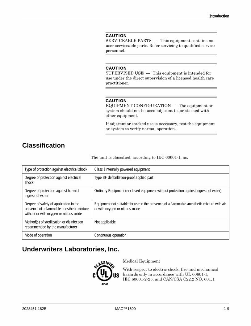
CAUTIONSERVICEABLE PARTS — This equipment contains no user serviceable parts. Refer servicing to qualified service personnel.
CAUTIONSUPERVISED USE — This equipment is intended for use under the direct supervision of a licensed health care practitioner.
CAUTIONEQUIPMENT CONFIGURATION — The equipment or system should not be used adjacent to, or stacked with other equipment.
If adjacent or stacked use is necessary, test the equipment or system to verify normal operation.
ClassificationThe unit is classified, according to IEC 60601-1, as:
Underwriters Laboratories, Inc.Medical Equipment
With respect to electric shock, fire and mechanical hazards only in accordance with UL 60601-1, IEC 60601-2-25, and CAN/CSA C22.2 NO. 601.1.
Type of protection against electrical shock Class I internally powered equipment
Degree of protection against electrical shock
Type BF defibrillation-proof applied part
Degree of protection against harmful ingress of water
Ordinary Equipment (enclosed equipment without protection against ingress of water).
Degree of safety of application in the presence of a flammable anesthetic mixture with air or with oxygen or nitrous oxide
Equipment not suitable for use in the presence of a flammable anesthetic mixture with air or with oxygen or nitrous oxide
Method(s) of sterilization or disinfection recommended by the manufacturer
Not applicable
Mode of operation Continuous operation

1-10 MAC™ 1600 2028451-182B
Introduction
BiocompatibilityThe parts of the product described in this operator’s manual, including all accessories, that come in contact with the patient during the intended use, fulfill the biocompatibility requirements of the applicable standards. If you have questions in this matter, please contact GE or its representatives.
Legal NoticeOur equipment contains several fields which can be filled in before performing an ECG. While some of these fields are required, some are optional and left to the user to assess whether they are needed to perform the exam. A field RACE is one of these optional fields. It has been acknowledged by the medical profession as useful to analyze some pathologies. You should be aware that, in some jurisdictions, the processing of data revealing an individual’s racial origin is subject to legal requirements, such as obtaining the patient’s prior consent. If you elect to collect this type of data, it is your responsibility to ensure that you comply with all applicable legal requirements.
Responsibility of the ManufacturerGE is responsible for the effects of safety, reliability, and performance only if:
Assembly operations, extensions, readjustments, modifications, or repairs are carried out by persons authorized by GE.
The electrical installation of the relevant room complies with the requirements of the appropriate regulations.
The equipment is used in accordance with the instructions for use.
General Information
Indications of Use
The MAC 1600 ECG Analysis System is a portable ECG acquisition, analysis, and recording system. It is intended:
to acquire, analyze, display, and record information from adult and pediatric populations,
to be used under the direct supervision of a licensed health care practitioner,
to be used by trained operators in a hospital or medical professional’s facility environment to record ECG signals from surface electrodes,
to offer two basic modes of operation: (1) resting ECG mode and (2) arrhythmia mode
to print 6 or 12 leads of ECGs,
Introduction
2028451-182B MAC™ 1600 1-11
to be upgradable to provide software options such as 12-lead ECG measurement and interpretive analysis,
to be upgradable with a third mode of operation: (3) Exercise mode for exercise stress testing, and
to provide for the optional transmission and reception of ECG data to and from a central ECG cardiovascular information system.
NOTEPediatric population is defined as patients between the ages of 0 and 15 years of age.
Arrhythmia detection is provided for the convenience or automatic documentation.
ContraindicationsThe MAC 1600 device is NOT intended:
to be used during patient transport,
to be used for intra-cardiac applications,
to be used as a vital signs physiological monitor, or
to provide alarms for Arrhythmia detection.
The Arrhythmia detection mode is provided for the convenience of automatic documentation.
Recording ECGs During DefibrillationIt is not necessary to remove the ECG electrodes prior to defibrillation; the patient signal is defibrillation-proof.
Use silver-silver chloride electrodes. A defibrillator discharge may cause stainless steel or silver electrodes to retain a residual charge, which could cause a polarization that will block the acquisition of the ECG signal for several minutes.
We recommend using non-polarizing disposable electrodes with defibrillation recovery ratings as specified in AAMI EC 12.3.2.2.4 (SilverTRACE family of electrodes). AAMI EC12 requires that the polarization potential of an electrode pair does not exceed 100 mV 5 seconds after a defibrillation discharge.
If other electrodes are used, disconnect the patient cable from the system before delivering the defibrillation shock.
NOTEIf excessive DC voltages are present at the electrode, then a message will appear indicating a Lead Off condition.
ADS (cubic spline correction) and the FRF algorithm cause a signal delay of approximately 2 seconds; therefore they should be disabled if the patient has to be defibrillated while the ECG is being recorded.

1-12 MAC™ 1600 2028451-182B
Introduction
Accuracy Of the Input Signal ReproductionOverall System Error is tested using the method described in AAMI EC11 3.2.7.1. Overall System Error is +5%.
Frequency Response is tested using the method described in AAMI EC11 3.2.7.2 methods A and D.
Modulating Effects in Digital SystemsThis device uses digital sampling techniques that may produce some variation in amplitudes of Q, R, and/or S waves from one heart beat to the next, which may be particularly noticeable in pediatric recordings. If this phenomenon is observed, the clinician should be aware that the origin of amplitude variations is not entirely physiologic. For measuring voltages of Q, R, and S waves, it is advisable to use the QRS complexes with the largest deflection of the particular waves.
Installation and ConnectionIf the installation of this equipment, in the USA, will use 240 V rather than 120 V, the source must be a center-tapped, 240 V, single-phase circuit.
Contact GE for information before connecting any devices to this equipment not recommended in this manual.
Parts and AccessoriesTo ensure patient safety, use only parts and accessories manufactured or recommended by GE. Browse to www.gehealthcare.com to obtain information about GE-recommended supplies and accessories.
Parts and accessories used must meet the requirements of the applicable IEC 601 series safety standards, and/or the system configuration must meet the requirements of the IEC 60601-1-1 medical electrical systems standard.
The use of ACCESSORY equipment not complying with the equivalent safety requirements of this equipment may lead to a reduced level of safety of the resulting system. Consideration relating to the choice shall include:
use of the accessory in the PATIENT VICINITY; and
evidence that the safety certification of the ACCESSORY has been performed in accordance to the appropriate IEC 60601-1 and/or IEC 60601-1-1 harmonized national standard.
Introduction
2028451-182B MAC™ 1600 1-13
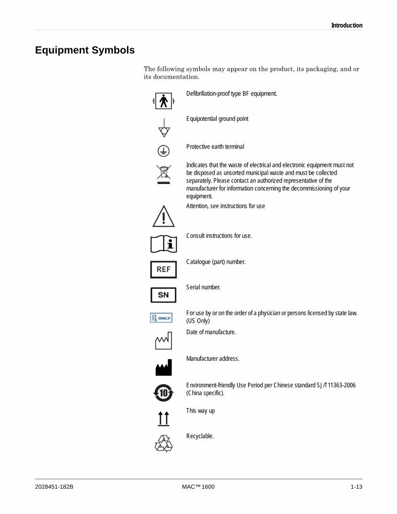
Equipment SymbolsThe following symbols may appear on the product, its packaging, and or its documentation.
Defibrillation-proof type BF equipment.
Equipotential ground point
Protective earth terminal
Indicates that the waste of electrical and electronic equipment must not be disposed as unsorted municipal waste and must be collected separately. Please contact an authorized representative of the manufacturer for information concerning the decommissioning of your equipment.Attention, see instructions for use
Consult instructions for use.
Catalogue (part) number.
Serial number.
For use by or on the order of a physician or persons licensed by state law. (US Only)Date of manufacture.
Manufacturer address.
Environment-friendly Use Period per Chinese standard SJ/T11363-2006 (China specific).
This way up
Recyclable.
1-14 MAC™ 1600 2028451-182B
Introduction
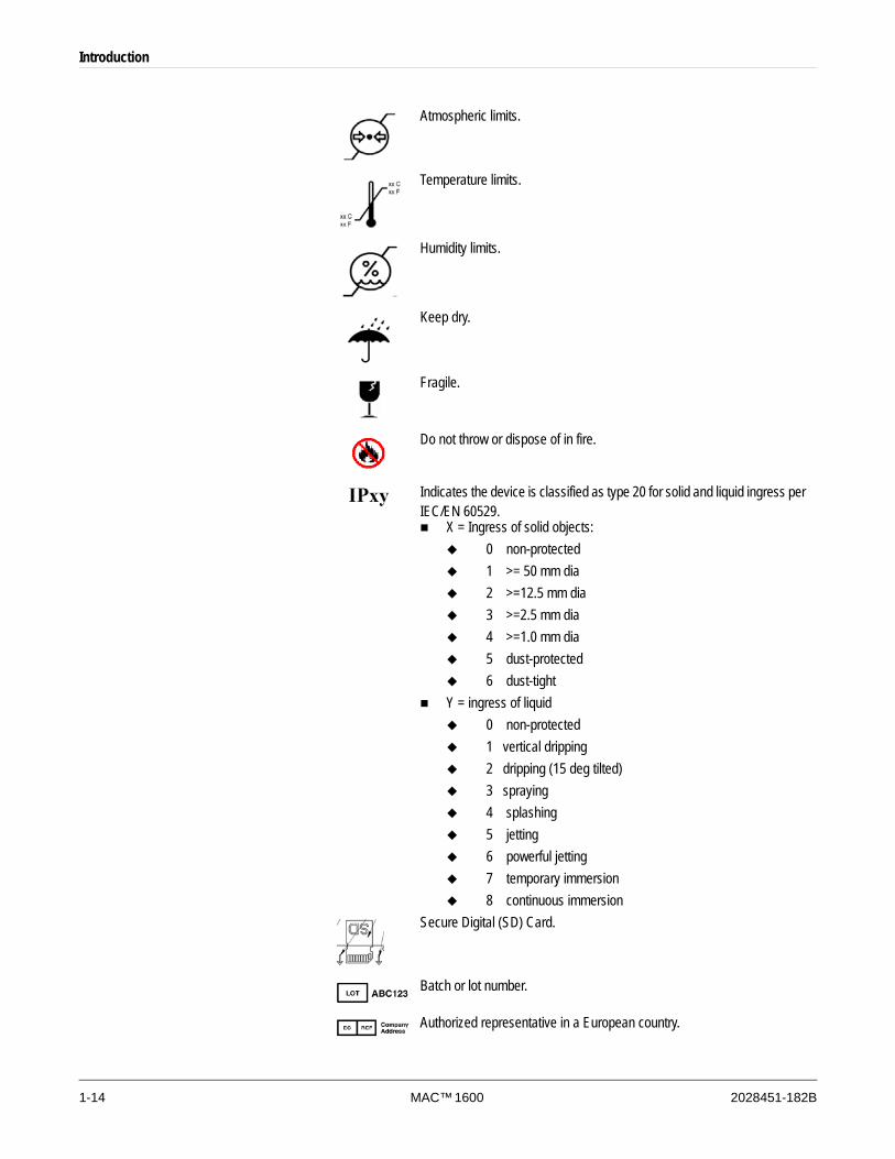
Atmospheric limits.
Temperature limits.
Humidity limits.
Keep dry.
Fragile.
Do not throw or dispose of in fire.
Indicates the device is classified as type 20 for solid and liquid ingress per IEC/EN 60529.
X = Ingress of solid objects:0 non-protected1 >= 50 mm dia2 >=12.5 mm dia3 >=2.5 mm dia4 >=1.0 mm dia5 dust-protected6 dust-tight
Y = ingress of liquid0 non-protected1 vertical dripping2 dripping (15 deg tilted)3 spraying4 splashing5 jetting6 powerful jetting7 temporary immersion8 continuous immersion
Secure Digital (SD) Card.
Batch or lot number.
Authorized representative in a European country.
Introduction
2028451-182B MAC™ 1600 1-15
Service Information
Service RequirementsRefer equipment servicing to GE authorized service personnel only. Any unauthorized attempt to repair equipment under warranty voids that warranty.
It is the user’s responsibility to report the need for service to GE or to one of their authorized agents.
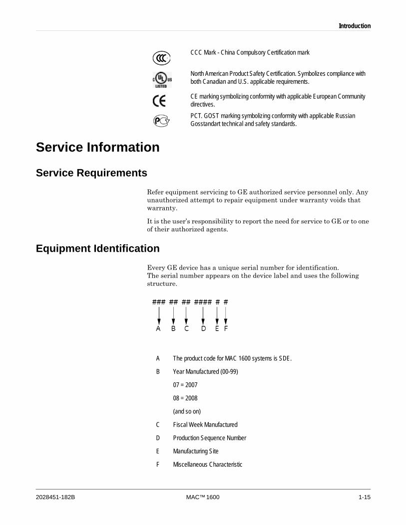
Equipment IdentificationEvery GE device has a unique serial number for identification. The serial number appears on the device label and uses the following structure.
CCC Mark - China Compulsory Certification mark
North American Product Safety Certification. Symbolizes compliance with both Canadian and U.S. applicable requirements.
CE marking symbolizing conformity with applicable European Community directives.PCT. GOST marking symbolizing conformity with applicable Russian Gosstandart technical and safety standards.
A The product code for MAC 1600 systems is SDE.
B Year Manufactured (00-99)
07 = 2007
08 = 2008
(and so on)
C Fiscal Week Manufactured
D Production Sequence Number
E Manufacturing Site
F Miscellaneous Characteristic

1-16 MAC™ 1600 2028451-182B
Introduction

2028451-182B MAC™ 1600 2-1
2 Equipment Overview
2-2 MAC™ 1600 2028451-182B
Equipment Overview
Equipment Description
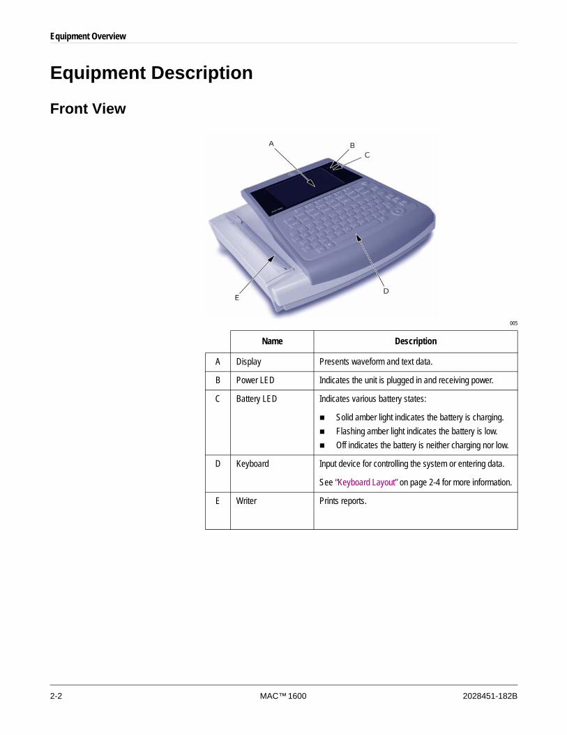
Front View
005
Name Description
A Display Presents waveform and text data.
B Power LED Indicates the unit is plugged in and receiving power.
C Battery LED Indicates various battery states:
Solid amber light indicates the battery is charging.Flashing amber light indicates the battery is low.Off indicates the battery is neither charging nor low.
D Keyboard Input device for controlling the system or entering data.
See “Keyboard Layout” on page 2-4 for more information.
E Writer Prints reports.
Equipment Overview
2028451-182B MAC™ 1600 2-3
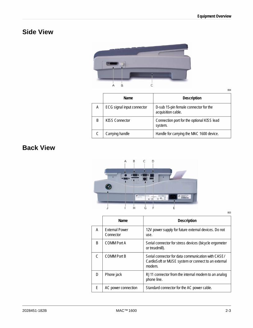
Side View
004
Back View
003
Name Description
A ECG signal input connector D-sub 15-pin female connector for the acquisition cable.
B KISS Connector Connection port for the optional KISS lead system.
C Carrying handle Handle for carrying the MAC 1600 device.
Name Description
A External Power Connector
12V power supply for future external devices. Do not use.
B COMM Port A Serial connector for stress devices (bicycle ergometer or treadmill).
C COMM Port B Serial connector for data communication with CASE/CardioSoft or MUSE system or connect to an external modem.
D Phone jack RJ11 connector from the internal modem to an analog phone line.
E AC power connection Standard connector for the AC power cable.
2-4 MAC™ 1600 2028451-182B
Equipment Overview
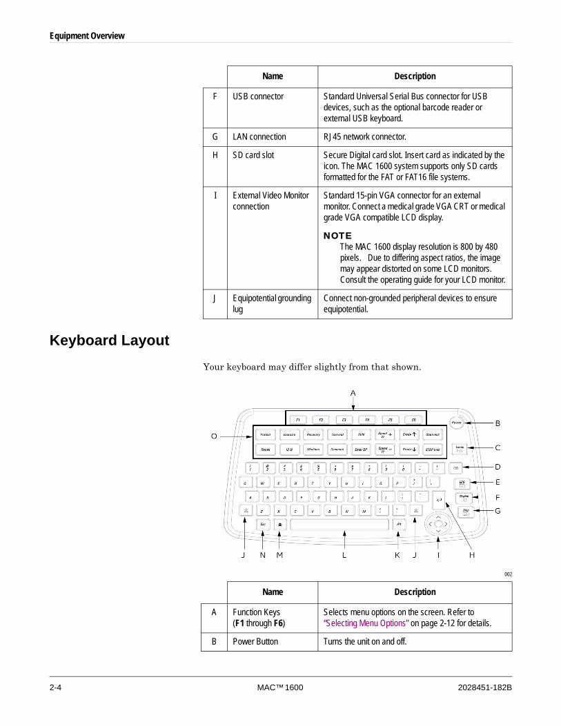
Keyboard LayoutYour keyboard may differ slightly from that shown.
002
F USB connector Standard Universal Serial Bus connector for USB devices, such as the optional barcode reader or external USB keyboard.
G LAN connection RJ45 network connector.
H SD card slot Secure Digital card slot. Insert card as indicated by the icon. The MAC 1600 system supports only SD cards formatted for the FAT or FAT16 file systems.
I External Video Monitor connection
Standard 15-pin VGA connector for an external monitor. Connect a medical grade VGA CRT or medical grade VGA compatible LCD display.
NOTEThe MAC 1600 display resolution is 800 by 480 pixels. Due to differing aspect ratios, the image may appear distorted on some LCD monitors. Consult the operating guide for your LCD monitor.
J Equipotential grounding lug
Connect non-grounded peripheral devices to ensure equipotential.
Name Description
Name Description
A Function Keys (F1 through F6)
Selects menu options on the screen. Refer to “Selecting Menu Options” on page 2-12 for details.
B Power Button Turns the unit on and off.

Equipment Overview
2028451-182B MAC™ 1600 2-5
C Leads key Changes the leads when the screen is being used to display waveforms.
D Backspace Key Deletes characters.
E ECG key Acquires a resting ECG, prints a 10-second report in Arrhythmia mode, and prints a 12-lead report in Stress mode.
F Rhythm key Prints a continuous, real-time rhythm strip. Press the Stop key to stop the rhythm strip from printing. (Rhythm report is not stored and cannot be transmitted.)
G Stop key Stops the writer from printing.
H Enter Key Advances the cursor in a window or to select items from the screen.
I Trimpad The arrows move the cursor left, right, up, or down. The center button moves the focus within a window or selects the currently active item.
J Shift Key Used in conjunction with letter keys to enter capital letters. For example, press shift + p to type a capital P.
K Alt key Not currently used by the system.
L Space Bar Adds a space between typed characters or to highlight screen items.
M Option Key Used in conjunction with other keys to enter special characters on non-English keyboards.
N Esc key Closes a window on the screen.
O Stress Keys These keys will be on your keyboard if your system has the stress option. See “Stress Test Keys” on page 7-5 for more information
Name Description
2-6 MAC™ 1600 2028451-182B
Equipment Overview
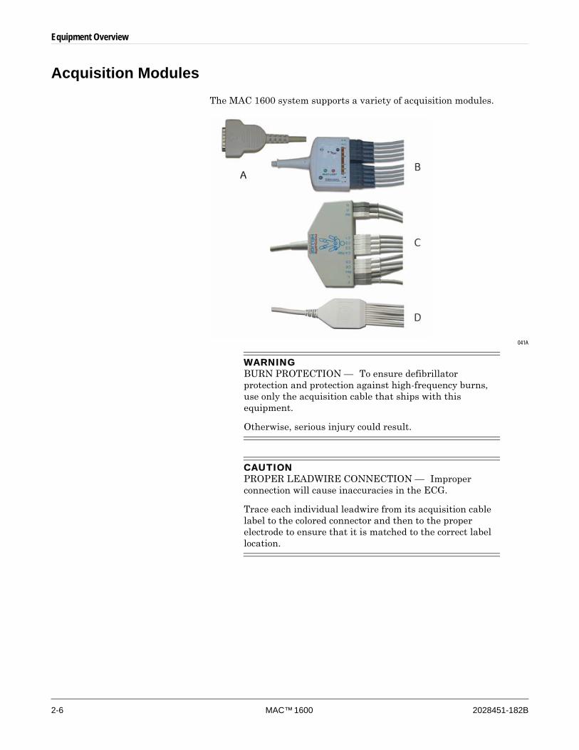
Acquisition ModulesThe MAC 1600 system supports a variety of acquisition modules.
041A
WARNINGBURN PROTECTION — To ensure defibrillator protection and protection against high-frequency burns, use only the acquisition cable that ships with this equipment.
Otherwise, serious injury could result.
CAUTIONPROPER LEADWIRE CONNECTION — Improper connection will cause inaccuracies in the ECG.
Trace each individual leadwire from its acquisition cable label to the colored connector and then to the proper electrode to ensure that it is matched to the correct label location.
Equipment Overview
2028451-182B MAC™ 1600 2-7
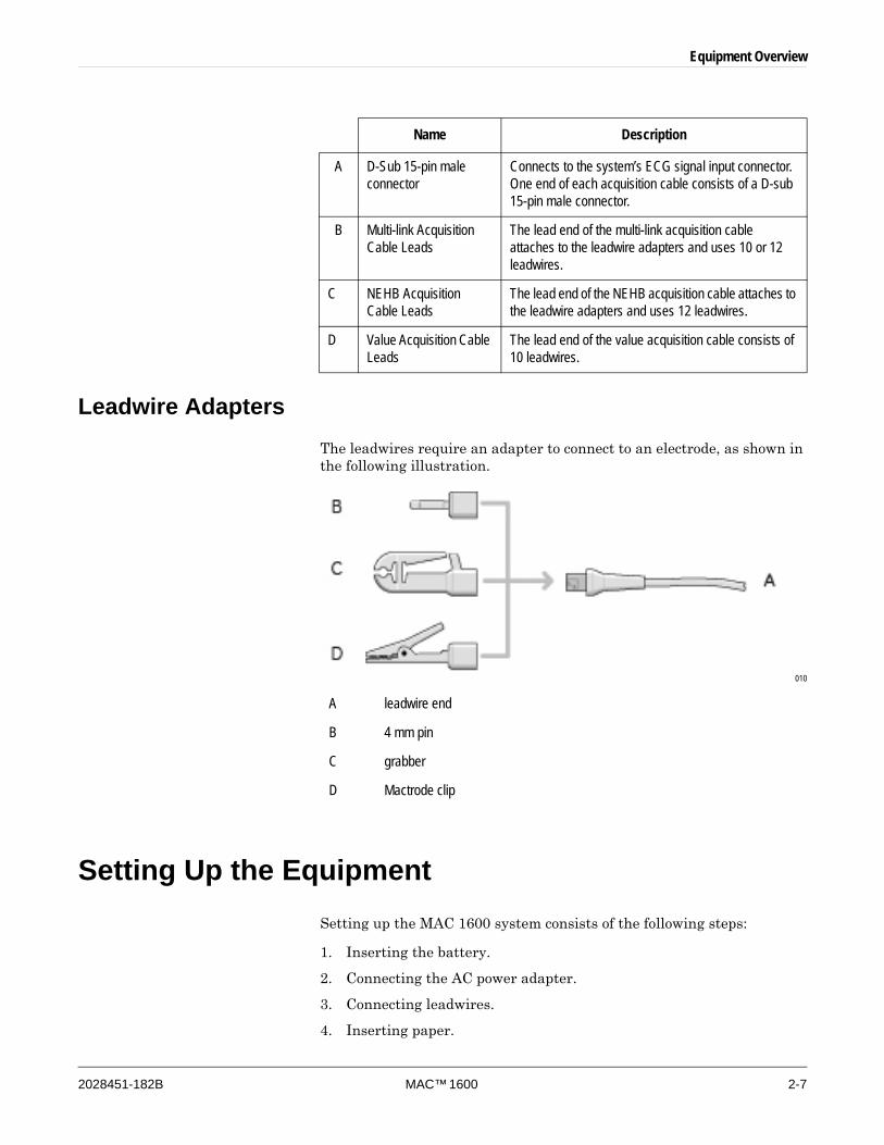
Leadwire AdaptersThe leadwires require an adapter to connect to an electrode, as shown in the following illustration.
010
Setting Up the EquipmentSetting up the MAC 1600 system consists of the following steps:
1. Inserting the battery.
2. Connecting the AC power adapter.
3. Connecting leadwires.
4. Inserting paper.
Name Description
A D-Sub 15-pin male connector
Connects to the system’s ECG signal input connector. One end of each acquisition cable consists of a D-sub 15-pin male connector.
B Multi-link Acquisition Cable Leads
The lead end of the multi-link acquisition cable attaches to the leadwire adapters and uses 10 or 12 leadwires.
C NEHB Acquisition Cable Leads
The lead end of the NEHB acquisition cable attaches to the leadwire adapters and uses 12 leadwires.
D Value Acquisition Cable Leads
The lead end of the value acquisition cable consists of 10 leadwires.
A leadwire end
B 4 mm pin
C grabber
D Mactrode clip
2-8 MAC™ 1600 2028451-182B
Equipment Overview
5. Connecting a barcode reader.
6. Connecting the optional internal modem.
7. Connecting an external modem.
8. Connecting an external stress device.
9. Turning on the unit.
10. Configuring the system.
11. Testing the equipment.
Each step is described in more detail on the following pages.
Inserting the BatteryThe MAC 1600 system is shipped with a lithium-ion battery that is charged when inserted into a MAC 1600 system connected to AC power. For instructions on inserting the battery, refer to “Replacing the Battery” on page 10-12.
NOTEDo not use the system on battery power until the battery is fully charged as indicated by the on-screen battery gauge and the blank LED next to the display. You may use the MAC 1600 system on AC power while the battery is charging.
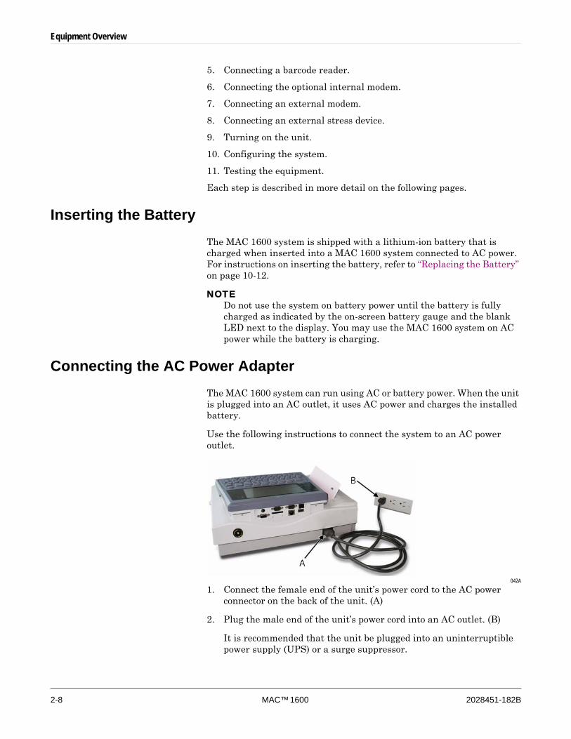
Connecting the AC Power AdapterThe MAC 1600 system can run using AC or battery power. When the unit is plugged into an AC outlet, it uses AC power and charges the installed battery.
Use the following instructions to connect the system to an AC power outlet.
042A
1. Connect the female end of the unit’s power cord to the AC power connector on the back of the unit. (A)
2. Plug the male end of the unit’s power cord into an AC outlet. (B)
It is recommended that the unit be plugged into an uninterruptible power supply (UPS) or a surge suppressor.
Equipment Overview
2028451-182B MAC™ 1600 2-9
3. Check the Power LED to make sure the unit is receiving power from the AC outlet.
For more information, refer to “Front View” on page 2-2.
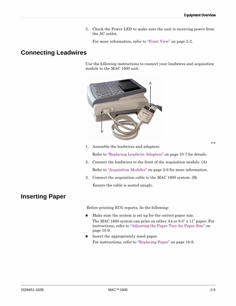
Connecting LeadwiresUse the following instructions to connect your leadwires and acquisition module to the MAC 1600 unit.
011A
1. Assemble the leadwires and adapters.
Refer to “Replacing Leadwire Adapters” on page 10-7 for details.
2. Connect the leadwires to the front of the acquisition module. (A)
Refer to “Acquisition Modules” on page 2-6 for more information.
3. Connect the acquisition cable to the MAC 1600 system. (B)
Ensure the cable is seated snugly.
Inserting Paper Before printing ECG reports, do the following:
Make sure the system is set up for the correct paper size.
The MAC 1600 system can print on either A4 or 8.5” x 11” paper. For instructions, refer to “Adjusting the Paper Tray for Paper Size” on page 10-9.
Insert the appropriately sized paper.
For instructions, refer to “Replacing Paper” on page 10-8.
2-10 MAC™ 1600 2028451-182B
Equipment Overview
Connecting the Barcode Reader If the optional barcode reader was purchased with the unit, connect it to the USB port on the MAC 1600 system.
NOTEThe BCRD option, which must be enabled in the system in order to use the reader, is activated at the factory when the barcode reader is purchased with the unit. However, the barcode settings must be configured for the site before the reader can be used. Refer to “Patient Setup” on page 9-24 for details.
Connecting the Optional Internal ModemIf the MAC 1600 system was purchased with the internal modem option, connect the modem to an analog phone line using the RJ11 connector on the back of the unit. See “Back View” on page 2-3 for details.
Connecting to an External ModemThe MAC 1600 system can be used with the Multitech MT5634ZBA Global Modem (PN 2004831-001). The modem can be connected to the system’s COMM B serial port using either the 350mm MAC 1200 cable (PN 2008683-001) or the 1M MAC 1200 cable (PN 2008683-002). The external modem is unnecessary if the optional internal modem was purchased.
Refer to “Back View” on page 2-3 for the location of COMM B. For complete instructions, refer to the MAC 1600 Field Service Manual.
Connecting to a LANIf the LANC (LAN Communication to CardioSoft) or LANM (LAN Communication to MUSE) options were purchased, connect an ethernet cable to the RJ45 network connector on the back of the MAC 1600 unit.
NOTEThis step applies only if the MAC 1600 unit will be used as a stationary device. If it will be used as a mobile unit, you will not connect the device to a LAN until you are ready to import, transmit, or export records.
Connecting External Devices (Stress Option)If the Stress option was purchased, connect the external stress device to the MAC 1600 system via a serial cable to the Comm A on the back panel.
The MAC 1600 system can work with any of the following devices.
GE model T2100 treadmill
Equipment Overview
2028451-182B MAC™ 1600 2-11
GE model T2000 treadmill
Trackmaster TMX425
Ergoline 900 ergometer (Sphygmomanometer in ergometer)
eBike ergometer
Variobike ergometer
Excalibur ergometer
Master’s Step (acoustic signal only)
NOTESet up the MAC 1600 system before using external devices. See “Basic Setup” on page 9-2 for information about setting up stress test devices.
Turning on the SystemPress the Power button to power on the system. Verify the MAC 1600 welcome screen appears with no errors:
If you encounter any problems powering on the system, refer to Appendix A for troubleshooting instructions.
Configuring the DeviceWhen the device is ready for operation, configure the system settings using the information in Chapter 9.
If the same settings will be applied to multiple devices at the site, export the settings to an SD card and use that card to import the settings to other MAC 1600 systems.
Testing the DeviceAfter the MAC 1600 unit has been set up and configured, test the device completely before using it with patients. Test scenarios include:
Conducting and printing a resting ECG
Refer to Chapter 5 for instructions on resting ECGs.
Conducting and printing an arrhythmia ECG
Refer to Chapter 6 for instructions on arrhythmia ECGs.
Conducting and printing a stress ECG
Refer to Chapter 7 for instructions on stress ECGs.
Saving, importing, printing, deleting, transmitting, and exporting records
Refer to Chapter 8 for instructions on using internal storage.

2-12 MAC™ 1600 2028451-182B
Equipment Overview
System Description
Start Up ScreenDepending on what options have been selected for Power up mode in Basic Setup, the start up screen will be one of the following:
Resting ECG
Stress ECG
Arrhythmia
Main Screen
A window prompting you to enter User ID and Password.
NOTEThe password window will appear only if the High Security Mode option is selected in Basic Setup. The system can be used to take a STAT ECG without having to log in. Press the F1 key to select STAT ECG to begin taking an ECG without logging into the MAC 1600 system.
Using the MAC 1600 KeyboardYou interact with the MAC 1600 system by using the keyboard. In addition to entering data as you would any keyboard, use it to:
Select menu options
Navigate through data entry fields
Control optional stress equipment
For a complete description of the MAC 1600 keyboard features, refer to “Keyboard Layout” on page 2-4 and “Stress Test Keys” on page 7-5.
Selecting Menu Options
You configure the device and initiate ECG readings by selecting menu options that appear across the bottom of the display. Up to six menu options may be available at any given time, and each option corresponds to a function key (F1–F6) directly below the display.
043A
Equipment Overview
2028451-182B MAC™ 1600 2-13
Press a function key to select the corresponding menu option. Depending on the selected option, one of the following results occurs:
Take an ECG
For example, selecting the Resting ECG menu option opens the Resting ECG function.
Change a setting
For example, during a resting ECG, selecting the 25 mm/s option changes the rate of the waveform.
Open a window
For example, the Patient Data option opens the Enter Patient Data window.
Change menu options
For example, the More option displays additional menu options.
Save your selections
After entering data or changing a configuration, you may have the option to save your changes by selecting the Save menu option.
Navigating Data Entry Windows
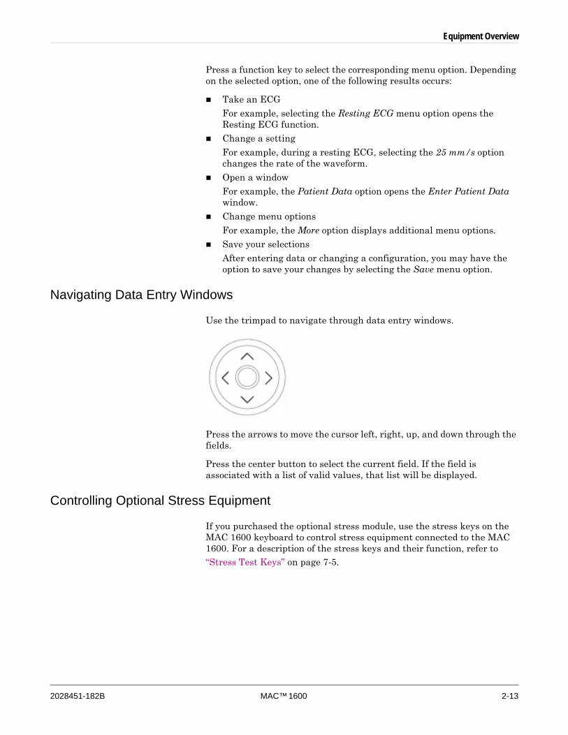
Use the trimpad to navigate through data entry windows.
Press the arrows to move the cursor left, right, up, and down through the fields.
Press the center button to select the current field. If the field is associated with a list of valid values, that list will be displayed.
Controlling Optional Stress Equipment
If you purchased the optional stress module, use the stress keys on the MAC 1600 keyboard to control stress equipment connected to the MAC 1600. For a description of the stress keys and their function, refer to “Stress Test Keys” on page 7-5.

2-14 MAC™ 1600 2028451-182B
Equipment Overview

2028451-182B MAC™ 1600 3-1
3 Preparing the Patient

3-2 MAC™ 1600 2028451-182B
Preparing the Patient
Prepare the Patient’s SkinCareful skin preparation is the key to an interference-free ECG. The signal quality is shown on the Hookup Advisor indicator.
NOTESee the KISS operator’s manual for instructions on how to use the KISS Electrode Application System. The KISS system is not available for sale in the United States.
25A
1. Shave any hair from each electrode site and degrease each electrode site with alcohol.
2. Do one of the following:
If you are conducting a stress test, proceed to step 3.
If you are not conducting a stress test, skip to step 5.
3. Mark each electrode site with a felt tip pen.
4. Remove the epidermal skin layer at each electrode site using an abrasive pad or skin preparation cream.
When you remove the mark left by the felt tip pen, the site is ready to apply the electrodes.
5. Apply electrode to prepared area.
Preparing the Patient
2028451-182B MAC™ 1600 3-3
WARNINGSHOCK HAZARD — Ensure that conductive parts of the electrodes or lead wires do not come in contact with other conductive parts, including earth.
This would cancel the protection provided by the isolated signal input.
6. Verify the leads are all connected and working properly.
NOTEYou can use the Hookup Advisor module to review connection quality before beginning the ECG. For more information, refer to “Hookup Advisor Module” on page 5-12.
Applying the Electrodes
CAUTIONPROPER LEADWIRE CONNECTION — Improper connection will cause inaccuracies in the ECG.
Trace each individual leadwire from its acquisition module label to the colored connector and then to the proper electrode to ensure that it is matched to the correct label location.
3-4 MAC™ 1600 2028451-182B
Preparing the Patient
Resting ECG Electrodes
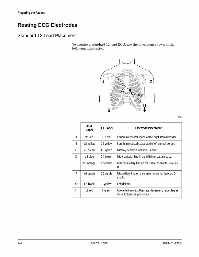
Standard 12 Lead Placement
To acquire a standard 12 lead ECG, use the placement shown in the following illustration.
026A
AHA Label IEC Label Electrode Placement
A V1 red C1 red Fourth intercostal space at the right sternal border.
B V2 yellow C2 yellow Fourth intercostal space at the left sternal border.
C V3 green C3 green Midway between location B and D.
D V4 blue C4 brown Mid-clavicular line in the fifth intercostal space.
E V5 orange C5 black Anterior axillary line on the same horizontal level as D.
F V6 purple C6 purple Mid-axillary line on the same horizontal level as D and E.
G LA black L yellow Left deltoid.
H LL red F green Above left ankle. (Alternate placement, upper leg as close to torso as possible.)
Preparing the Patient
2028451-182B MAC™ 1600 3-5
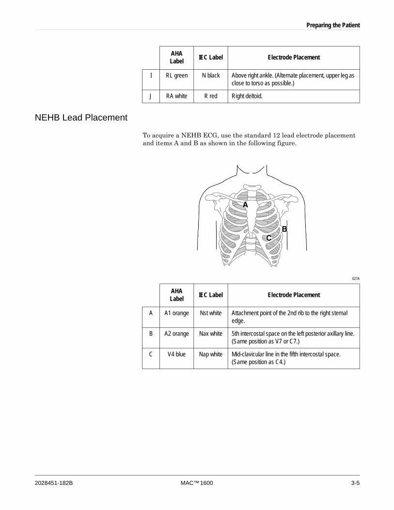
NEHB Lead Placement
To acquire a NEHB ECG, use the standard 12 lead electrode placement and items A and B as shown in the following figure.
027A
I RL green N black Above right ankle. (Alternate placement, upper leg as close to torso as possible.)
J RA white R red Right deltoid.
AHA Label IEC Label Electrode Placement
AHA Label IEC Label Electrode Placement
A A1 orange Nst white Attachment point of the 2nd rib to the right sternal edge.
B A2 orange Nax white 5th intercostal space on the left posterior axillary line. (Same position as V7 or C7.)
C V4 blue Nap white Mid-clavicular line in the fifth intercostal space. (Same position as C4.)
3-6 MAC™ 1600 2028451-182B
Preparing the Patient
Stress ECG Electrodes
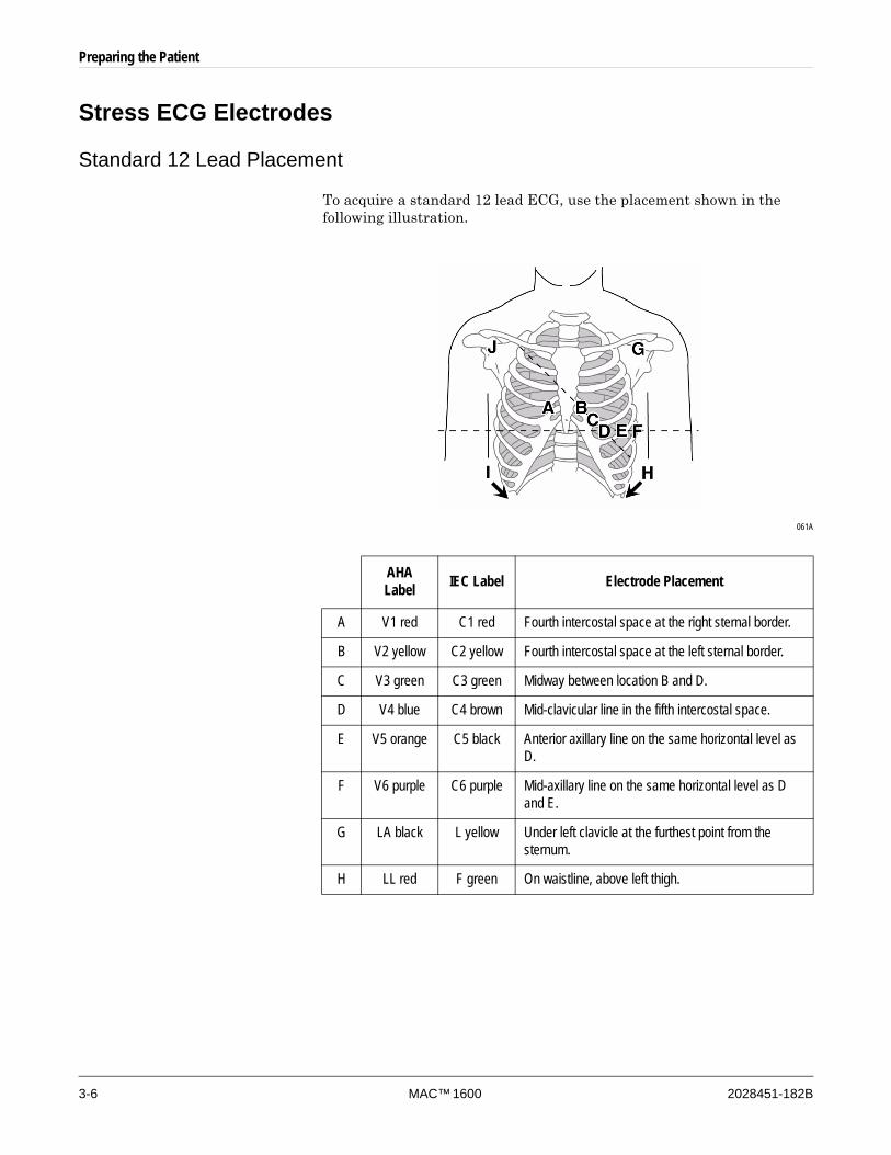
Standard 12 Lead Placement
To acquire a standard 12 lead ECG, use the placement shown in the following illustration.
061A
AHA Label IEC Label Electrode Placement
A V1 red C1 red Fourth intercostal space at the right sternal border.
B V2 yellow C2 yellow Fourth intercostal space at the left sternal border.
C V3 green C3 green Midway between location B and D.
D V4 blue C4 brown Mid-clavicular line in the fifth intercostal space.
E V5 orange C5 black Anterior axillary line on the same horizontal level as D.
F V6 purple C6 purple Mid-axillary line on the same horizontal level as D and E.
G LA black L yellow Under left clavicle at the furthest point from the sternum.
H LL red F green On waistline, above left thigh.

Preparing the Patient
2028451-182B MAC™ 1600 3-7
I RL green N black On waistline, above right thigh.
J RA white R red Under right clavicle at furthest point from the sternum.
AHA Label IEC Label Electrode Placement

3-8 MAC™ 1600 2028451-182B
Preparing the Patient

2028451-182B MAC™ 1600 4-1
4 Entering Patient Information
4-2 MAC™ 1600 2028451-182B
Entering Patient Information
Entering Patient Information Manually Patient information should be entered for each new patient from whom readings are taken. Use the following procedure to enter the information if you do not use a barcode reader or if you want to modify or add to the patient data entered with a barcode reader.
CAUTIONACCURATE PATIENT INFORMATION — Patient information may be retained from a previous patient. Be sure to check the patient information screen for each new patient. Data assigned to the wrong patient causes erroneous patient information that can affect diagnosis and treatment of the patient(s).
Make sure that you enter patient information for the correct patient.
1. Open the Enter Patient Data window.
For Resting ECG, the window is opened by pressing the F1 key.
For Arrhythmia or Stress, the window opens automatically when you initially select the application. You do not need to press the F1 key. For subsequent patients, you need manually open the window:
In Arrhythmia mode, press F1 > F2 (Start Recording > New Patient) to reopen the Enter Patient Data window.
In Stress mode, press F1 (Patient Data) to reopen the Enter Patient Data window.
2. Enter the necessary patient information. or press the F1 key to select a patient from the Patient List.
NOTEThe Patient List is available only if the optional internal storage is enabled.
If you select a patient from the patient list, only the first page of patient information is reused: all subsequent pages must be entered manually.
3. Use the F3 and F4 keys to move backward and forward through the patient data windows.
The F4 key moves forward one screen.
The F3 key moves backward one screen.
NOTEIf the CTDG (Clinical Trial Data Guard) option is activated, you enter clinical trial data on the last window.
4. When all the patient data has been entered, press the F6 key to save the data.
Entering Patient Information
2028451-182B MAC™ 1600 4-3
Entering Patient Information with a Barcode ReaderUsing a barcode reader can simplify the entry of patient information and reduce the chance of introducing errors. When you scan a patient’s barcode, it retrieves the patient information encoded in the barcode. You can then verify or modify the information as appropriate.
To use the barcode reader, it must be connected to the USB port on the MAC 1600 back panel and properly configured. Refer to Chapter 9 for instructions on setting up the optional barcode reader.
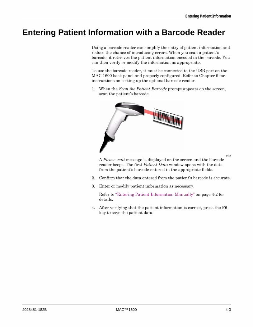
1. When the Scan the Patient Barcode prompt appears on the screen, scan the patient’s barcode.
044A
A Please wait message is displayed on the screen and the barcode reader beeps. The first Patient Data window opens with the data from the patient’s barcode entered in the appropriate fields.
2. Confirm that the data entered from the patient’s barcode is accurate.
3. Enter or modify patient information as necessary.
Refer to “Entering Patient Information Manually” on page 4-2 for details.
4. After verifying that the patient information is correct, press the F6 key to save the patient data.

4-4 MAC™ 1600 2028451-182B
Entering Patient Information

2028451-182B MAC™ 1600 5-1
5 Recording a Resting ECG
5-2 MAC™ 1600 2028451-182B
Recording a Resting ECG
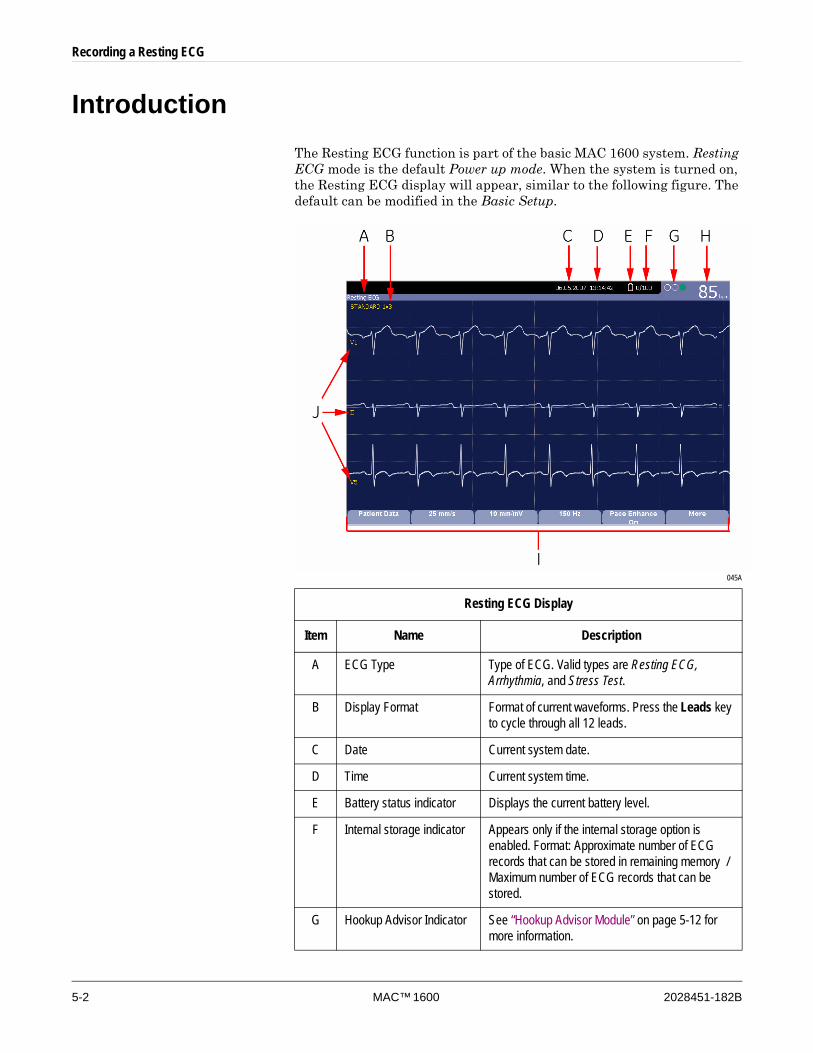
IntroductionThe Resting ECG function is part of the basic MAC 1600 system. Resting ECG mode is the default Power up mode. When the system is turned on, the Resting ECG display will appear, similar to the following figure. The default can be modified in the Basic Setup.
045A
Resting ECG Display
Item Name Description
A ECG Type Type of ECG. Valid types are Resting ECG, Arrhythmia, and Stress Test.
B Display Format Format of current waveforms. Press the Leads key to cycle through all 12 leads.
C Date Current system date.
D Time Current system time.
E Battery status indicator Displays the current battery level.
F Internal storage indicator Appears only if the internal storage option is enabled. Format: Approximate number of ECG records that can be stored in remaining memory / Maximum number of ECG records that can be stored.
G Hookup Advisor Indicator See “Hookup Advisor Module” on page 5-12 for more information.
Recording a Resting ECG
2028451-182B MAC™ 1600 5-3
Resting ECGsA resting ECG is the default mode of the MAC 1600, although this may be changed in the system configuration. This section describes how to record a resting ECG as well as the available options.
Recording a Resting ECGThe following steps describe how to conduct a resting ECG.
NOTETo take a stat ECG, skip directly to step 7.
1. Prepare the patient as described in Chapter 3.
2. Verify the system is in Resting ECG mode.
If the system is not in the Resting ECG mode, press the F1 key at the Main Menu to select Resting ECG.
3. Enter the patient data as described in Chapter 4.
4. Adjust the Speed, Gain, and Low Pass Filter until the waveforms are configured as desired.
For more information, refer to “ECG Options” on page 5-4.
5. If the patient has a pacemaker, press the F5 key to turn Pace Enhance on.
For more information, refer to “ECG Options” on page 5-4.
6. Press the Leads key to scroll through the leads or change the lead format.
For more information on display formats, refer to “Resting ECG Setup” on page 9-6.
H Patient’s Heart Rate Current patient heart rate measured in beats per minute.
I Menu Options The available menu options. The list of available options changes depending on the function and the current location within that function. For more information, refer to “Selecting Menu Options” on page 2-12.
J Lead Labels Identifies each waveform and indicates waveform quality. Yellow = a noisy lead. Red = disconnected lead.
Resting ECG Display (Continued)
Item Name Description
5-4 MAC™ 1600 2028451-182B
Recording a Resting ECG
7. When the waveforms are configured, press the ECG key to begin the acquisition.
A progress bar indicates the percentage of the data acquired. When the acquisition is complete, one of two things will occur, depending on the setting of the Preview Before Analysis option on the Resting ECG Setup window.
If the Preview Before Analysis option is enabled, a preview of the 10 second ECG is shown on the display. Proceed to step 8.
If the Preview Before Analysis option is not enabled, the ECG data will be analyzed and printed after it has been acquired. Skip to step 9.
8. While reviewing the preview, do one of the following.
To discard the reading and begin over, press F3 (Cancel) and repeat from step 4.
To accept the reading, press F4 (Continue).
The menu options change to allow you to manage the acquisition. Proceed to step 9.
9. Use the options to change patients, to print a copy, or to save, transmit, or reanalyze the data.
For more information on each option, refer to “Post-Acquisition Options” on page 5-6.
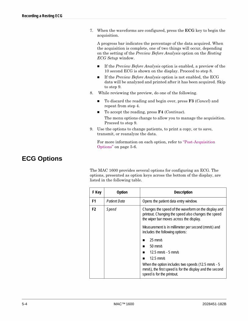
ECG OptionsThe MAC 1600 provides several options for configuring an ECG. The options, presented as option keys across the bottom of the display, are listed in the following table.
F Key Option Description
F1 Patient Data Opens the patient data entry window.
F2 Speed Changes the speed of the waveform on the display and printout. Changing the speed also changes the speed the wiper bar moves across the display.
Measurement is in millimeter per second (mm/s) and includes the following options:
25 mm/s50 mm/s12.5 mm/s - 5 mm/s12.5 mm/s
When the option includes two speeds (12.5 mm/s - 5 mm/s), the first speed is for the display and the second speed is for the printout.
Recording a Resting ECG
2028451-182B MAC™ 1600 5-5
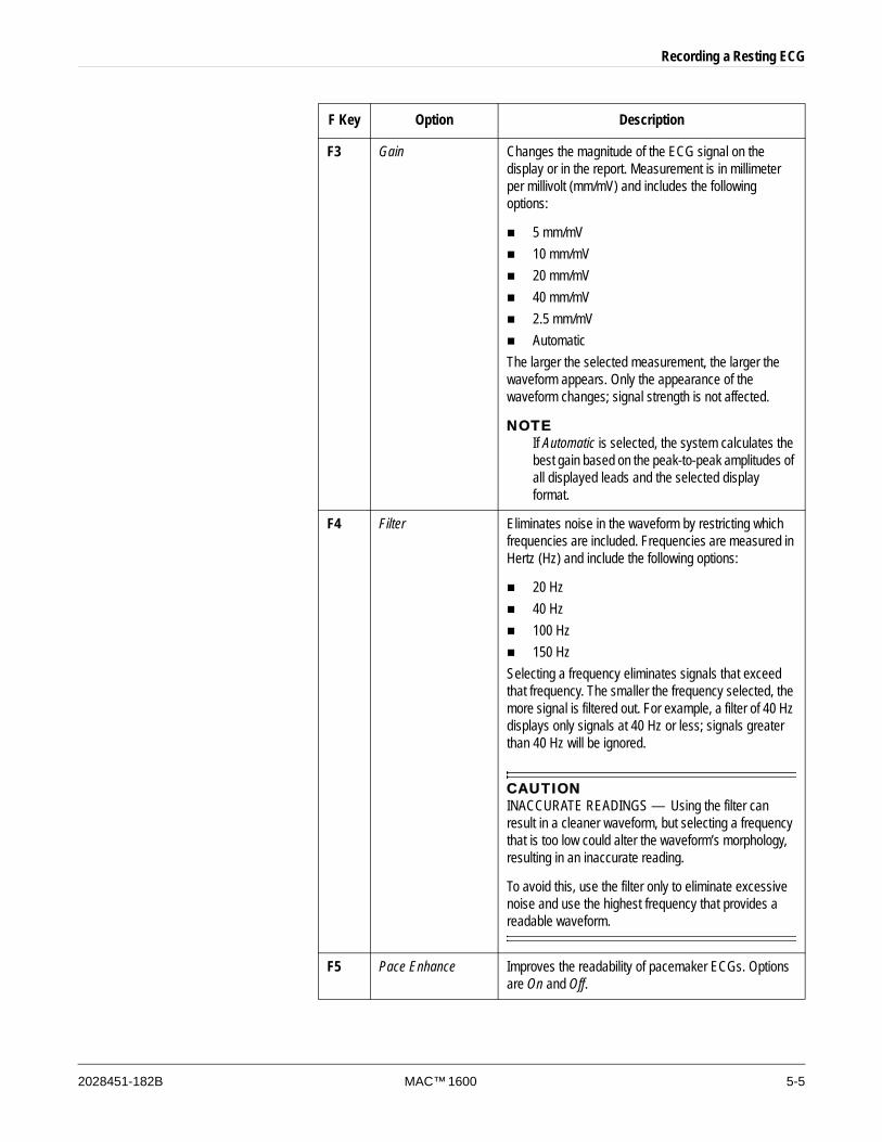
F3 Gain Changes the magnitude of the ECG signal on the display or in the report. Measurement is in millimeter per millivolt (mm/mV) and includes the following options:
5 mm/mV10 mm/mV20 mm/mV40 mm/mV2.5 mm/mVAutomatic
The larger the selected measurement, the larger the waveform appears. Only the appearance of the waveform changes; signal strength is not affected.
NOTEIf Automatic is selected, the system calculates the best gain based on the peak-to-peak amplitudes of all displayed leads and the selected display format.
F4 Filter Eliminates noise in the waveform by restricting which frequencies are included. Frequencies are measured in Hertz (Hz) and include the following options:
20 Hz40 Hz100 Hz150 Hz
Selecting a frequency eliminates signals that exceed that frequency. The smaller the frequency selected, the more signal is filtered out. For example, a filter of 40 Hz displays only signals at 40 Hz or less; signals greater than 40 Hz will be ignored.
CAUTIONINACCURATE READINGS — Using the filter can result in a cleaner waveform, but selecting a frequency that is too low could alter the waveform’s morphology, resulting in an inaccurate reading.
To avoid this, use the filter only to eliminate excessive noise and use the highest frequency that provides a readable waveform.
F5 Pace Enhance Improves the readability of pacemaker ECGs. Options are On and Off.
F Key Option Description
5-6 MAC™ 1600 2028451-182B
Recording a Resting ECG
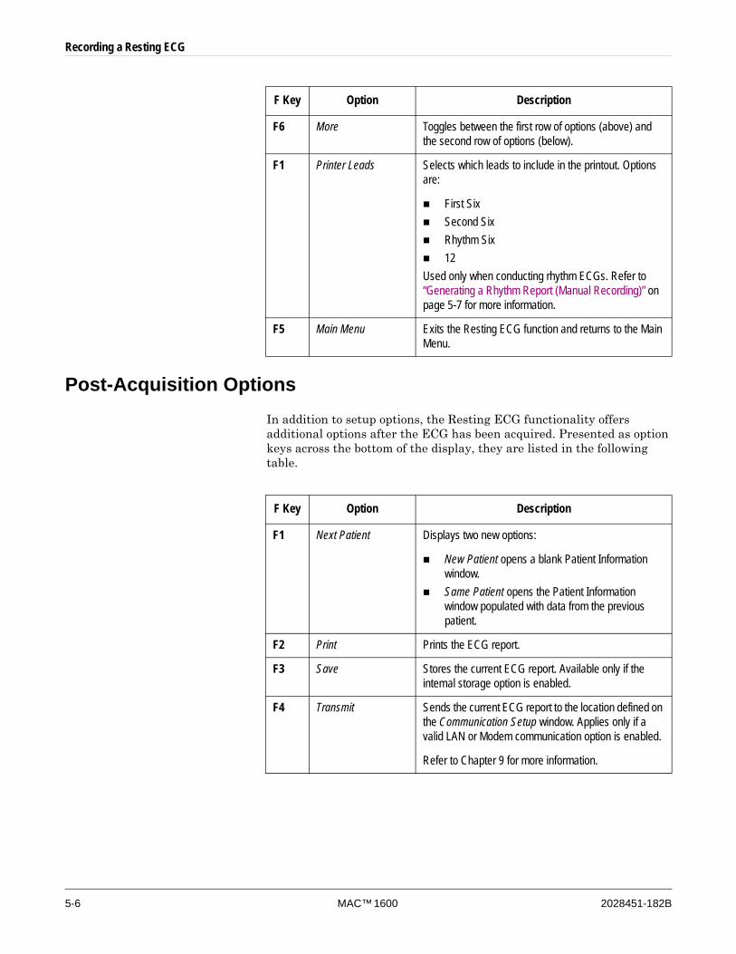
Post-Acquisition OptionsIn addition to setup options, the Resting ECG functionality offers additional options after the ECG has been acquired. Presented as option keys across the bottom of the display, they are listed in the following table.
F6 More Toggles between the first row of options (above) and the second row of options (below).
F1 Printer Leads Selects which leads to include in the printout. Options are:
First SixSecond SixRhythm Six12
Used only when conducting rhythm ECGs. Refer to “Generating a Rhythm Report (Manual Recording)” on page 5-7 for more information.
F5 Main Menu Exits the Resting ECG function and returns to the Main Menu.
F Key Option Description
F Key Option Description
F1 Next Patient Displays two new options:
New Patient opens a blank Patient Information window. Same Patient opens the Patient Information window populated with data from the previous patient.
F2 Print Prints the ECG report.
F3 Save Stores the current ECG report. Available only if the internal storage option is enabled.
F4 Transmit Sends the current ECG report to the location defined on the Communication Setup window. Applies only if a valid LAN or Modem communication option is enabled.
Refer to Chapter 9 for more information.
Recording a Resting ECG
2028451-182B MAC™ 1600 5-7
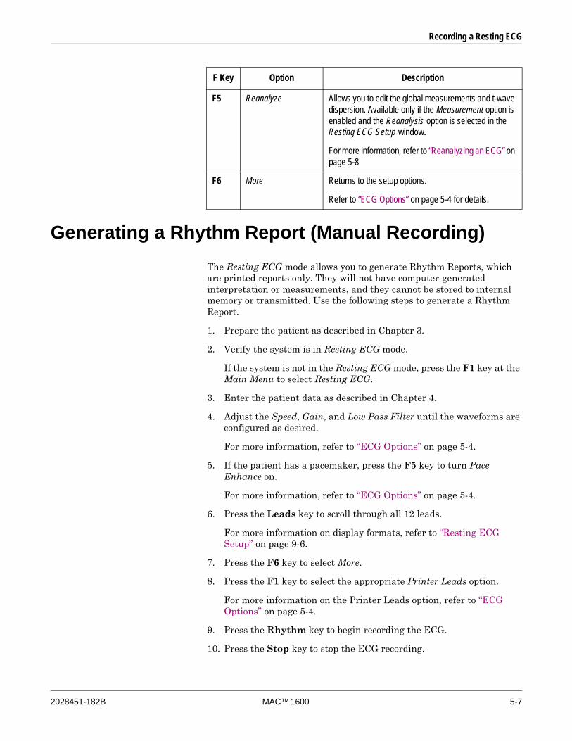
Generating a Rhythm Report (Manual Recording) The Resting ECG mode allows you to generate Rhythm Reports, which are printed reports only. They will not have computer-generated interpretation or measurements, and they cannot be stored to internal memory or transmitted. Use the following steps to generate a Rhythm Report.
1. Prepare the patient as described in Chapter 3.
2. Verify the system is in Resting ECG mode.
If the system is not in the Resting ECG mode, press the F1 key at the Main Menu to select Resting ECG.
3. Enter the patient data as described in Chapter 4.
4. Adjust the Speed, Gain, and Low Pass Filter until the waveforms are configured as desired.
For more information, refer to “ECG Options” on page 5-4.
5. If the patient has a pacemaker, press the F5 key to turn Pace Enhance on.
For more information, refer to “ECG Options” on page 5-4.
6. Press the Leads key to scroll through all 12 leads.
For more information on display formats, refer to “Resting ECG Setup” on page 9-6.
7. Press the F6 key to select More.
8. Press the F1 key to select the appropriate Printer Leads option.
For more information on the Printer Leads option, refer to “ECG Options” on page 5-4.
9. Press the Rhythm key to begin recording the ECG.
10. Press the Stop key to stop the ECG recording.
F5 Reanalyze Allows you to edit the global measurements and t-wave dispersion. Available only if the Measurement option is enabled and the Reanalysis option is selected in the Resting ECG Setup window.
For more information, refer to “Reanalyzing an ECG” on page 5-8
F6 More Returns to the setup options.
Refer to “ECG Options” on page 5-4 for details.
F Key Option Description

5-8 MAC™ 1600 2028451-182B
Recording a Resting ECG
If you press the Rhythm key after pressing the Stop key, the new report will either begin printing immediately on the current sheet of paper or advance to a new page, depending on the setting of the Start rhythm report on a new page field on the Resting ECG Setup window. Refer to “Resting ECG Setup” on page 9-6 for details.
ECG ReanalysisYou can reanalyze ECGs if both of the following conditions have been met:
Either the Measurement and 12SL Interpretation system option or the HEART system option is enabled, and
Reanalysis is selected on the Resting ECG Setup window.
Reanalysis allows you to modify the fiducial points on acquired waveforms. The details of what modifications can be made depends on which system option is enabled:
If the Measurement and 12SL Interpretation option is enabled, reanalysis allows you to modify Global Measurements.
If the HEART option is enabled, reanalysis allows you to modify both Global Measurements and T wave Dispersion.
Reanalyzing an ECGUse the following procedure to reanalyze a resting ECG.
For additional information, refer to “Reanalysis Layout” on page 5-9 and “Reanalysis Options” on page 5-10.
1. After acquiring an ECG, press the F5 key (Reanalyze) to run the Reanalyze function.
For instructions on acquiring a resting ECG, refer to “Recording a Resting ECG” on page 5-3.
2. Press the F3 key to select the Edit Mode.
For more information, refer to “Reanalysis Options” on page 5-10.
3. Review the waveforms to determine the accuracy of the system-selected fiducial points.
For a better view of individual waveforms, use the Leads key to toggle through the waveforms.
4. After you have analyzed the waveforms, use the following procedure to adjust the fiducial points:
a. Press the F1 key to toggle through the fiducial points.
The selected point changes size and is highlighted green.
Recording a Resting ECG
2028451-182B MAC™ 1600 5-9
b. When the correct point is selected, use the trimpad to adjust its position.
c. To verify correct positioning, refer to the values in the Measurement Legend in the lower left corner of the display.
For more information on the Measurement Legend, refer to “Reanalysis Layout” on page 5-9.
d. Repeat step a through step c for each fiducial point to be adjusted.
5. When you are done adjusting the fiducial points, do one of the following:
To discard your adjustments and start over, press the F4 key.
The original readings are restored. Return to step 2 to start over.
To save your adjustments, press the F5 key.
The changes are saved
6. Repeat from step 2 to make adjustments in the other edit mode.
7. After all your changes have been made, press the F6 key to return to the original menu options.
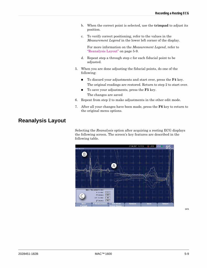
Reanalysis LayoutSelecting the Reanalysis option after acquiring a resting ECG displays the following screen. The screen’s key features are described in the following table.
047A
5-10 MAC™ 1600 2028451-182B
Recording a Resting ECG
Reanalysis OptionsThe following options are available when reanalyzing an ECG.
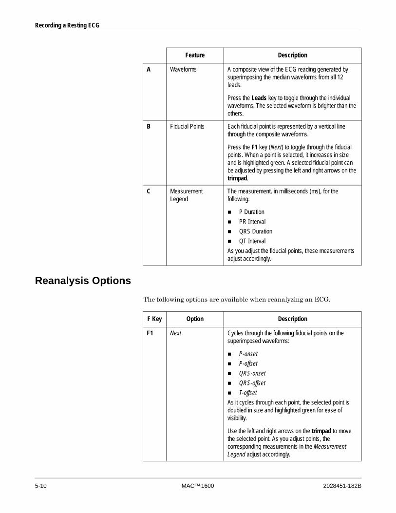
Feature Description
A Waveforms A composite view of the ECG reading generated by superimposing the median waveforms from all 12 leads.
Press the Leads key to toggle through the individual waveforms. The selected waveform is brighter than the others.
B Fiducial Points Each fiducial point is represented by a vertical line through the composite waveforms.
Press the F1 key (Next) to toggle through the fiducial points. When a point is selected, it increases in size and is highlighted green. A selected fiducial point can be adjusted by pressing the left and right arrows on the trimpad.
C Measurement Legend
The measurement, in milliseconds (ms), for the following:
P DurationPR IntervalQRS DurationQT Interval
As you adjust the fiducial points, these measurements adjust accordingly.
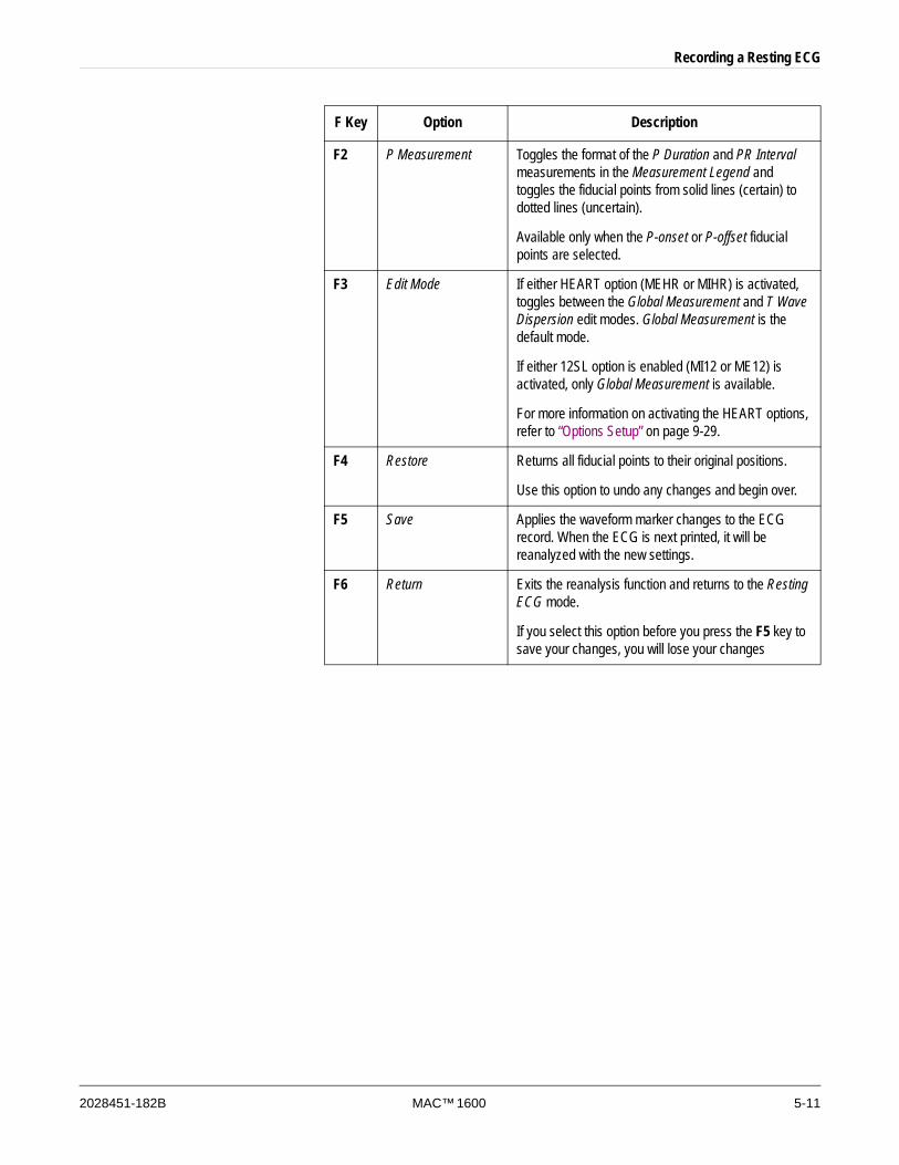
F Key Option Description
F1 Next Cycles through the following fiducial points on the superimposed waveforms:
P-onsetP-offsetQRS-onsetQRS-offsetT-offset
As it cycles through each point, the selected point is doubled in size and highlighted green for ease of visibility.
Use the left and right arrows on the trimpad to move the selected point. As you adjust points, the corresponding measurements in the Measurement Legend adjust accordingly.
Recording a Resting ECG
2028451-182B MAC™ 1600 5-11
F2 P Measurement Toggles the format of the P Duration and PR Interval measurements in the Measurement Legend and toggles the fiducial points from solid lines (certain) to dotted lines (uncertain).
Available only when the P-onset or P-offset fiducial points are selected.
F3 Edit Mode If either HEART option (MEHR or MIHR) is activated, toggles between the Global Measurement and T Wave Dispersion edit modes. Global Measurement is the default mode.
If either 12SL option is enabled (MI12 or ME12) is activated, only Global Measurement is available.
For more information on activating the HEART options, refer to “Options Setup” on page 9-29.
F4 Restore Returns all fiducial points to their original positions.
Use this option to undo any changes and begin over.
F5 Save Applies the waveform marker changes to the ECG record. When the ECG is next printed, it will be reanalyzed with the new settings.
F6 Return Exits the reanalysis function and returns to the Resting ECG mode.
If you select this option before you press the F5 key to save your changes, you will lose your changes
F Key Option Description
5-12 MAC™ 1600 2028451-182B
Recording a Resting ECG
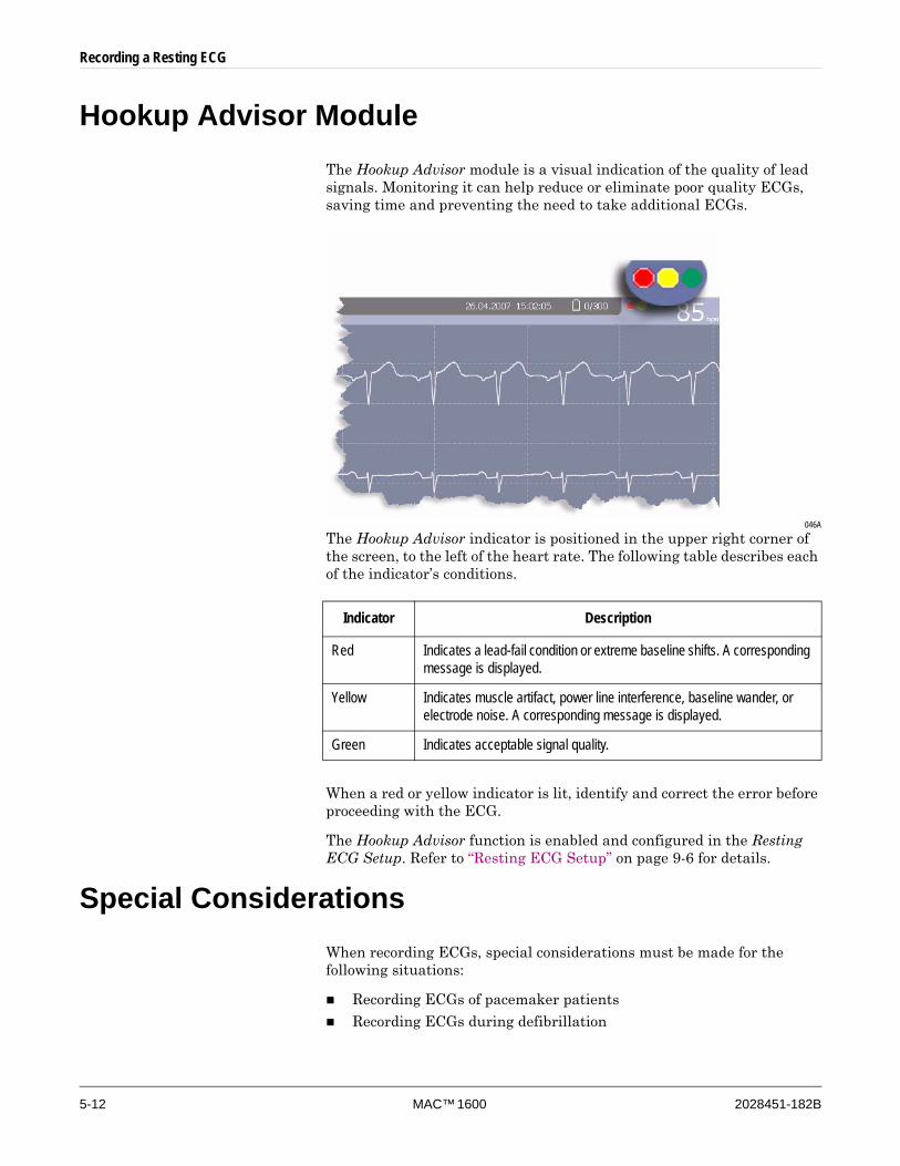
Hookup Advisor ModuleThe Hookup Advisor module is a visual indication of the quality of lead signals. Monitoring it can help reduce or eliminate poor quality ECGs, saving time and preventing the need to take additional ECGs.
046A
The Hookup Advisor indicator is positioned in the upper right corner of the screen, to the left of the heart rate. The following table describes each of the indicator’s conditions.
When a red or yellow indicator is lit, identify and correct the error before proceeding with the ECG.
The Hookup Advisor function is enabled and configured in the Resting ECG Setup. Refer to “Resting ECG Setup” on page 9-6 for details.
Special ConsiderationsWhen recording ECGs, special considerations must be made for the following situations:
Recording ECGs of pacemaker patients
Recording ECGs during defibrillation
Indicator Description
Red Indicates a lead-fail condition or extreme baseline shifts. A corresponding message is displayed.
Yellow Indicates muscle artifact, power line interference, baseline wander, or electrode noise. A corresponding message is displayed.
Green Indicates acceptable signal quality.
Recording a Resting ECG
2028451-182B MAC™ 1600 5-13
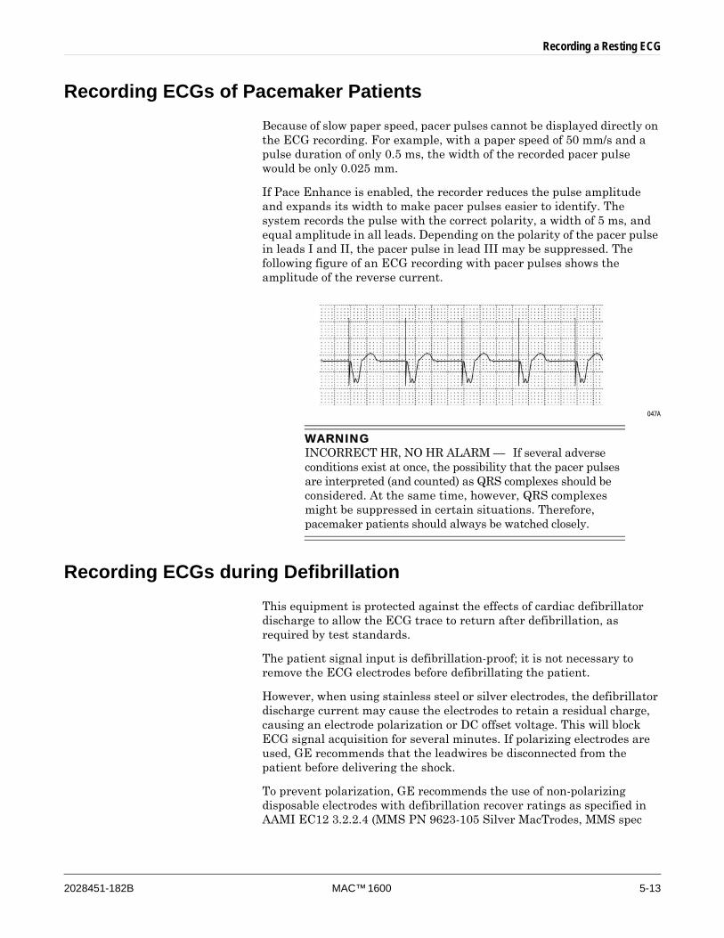
Recording ECGs of Pacemaker PatientsBecause of slow paper speed, pacer pulses cannot be displayed directly on the ECG recording. For example, with a paper speed of 50 mm/s and a pulse duration of only 0.5 ms, the width of the recorded pacer pulse would be only 0.025 mm.
If Pace Enhance is enabled, the recorder reduces the pulse amplitude and expands its width to make pacer pulses easier to identify. The system records the pulse with the correct polarity, a width of 5 ms, and equal amplitude in all leads. Depending on the polarity of the pacer pulse in leads I and II, the pacer pulse in lead III may be suppressed. The following figure of an ECG recording with pacer pulses shows the amplitude of the reverse current.
047A
WARNINGINCORRECT HR, NO HR ALARM — If several adverse conditions exist at once, the possibility that the pacer pulses are interpreted (and counted) as QRS complexes should be considered. At the same time, however, QRS complexes might be suppressed in certain situations. Therefore, pacemaker patients should always be watched closely.
Recording ECGs during DefibrillationThis equipment is protected against the effects of cardiac defibrillator discharge to allow the ECG trace to return after defibrillation, as required by test standards.
The patient signal input is defibrillation-proof; it is not necessary to remove the ECG electrodes before defibrillating the patient.
However, when using stainless steel or silver electrodes, the defibrillator discharge current may cause the electrodes to retain a residual charge, causing an electrode polarization or DC offset voltage. This will block ECG signal acquisition for several minutes. If polarizing electrodes are used, GE recommends that the leadwires be disconnected from the patient before delivering the shock.
To prevent polarization, GE recommends the use of non-polarizing disposable electrodes with defibrillation recover ratings as specified in AAMI EC12 3.2.2.4 (MMS PN 9623-105 Silver MacTrodes, MMS spec

5-14 MAC™ 1600 2028451-182B
Recording a Resting ECG
TP9623-003), which requires the polarization potential of an electrode pair not exceed 100mV five seconds after a defibrillation discharge.
WARNINGEQUIPMENT DAMAGE — For patient safety, use only the original GE patient cable. Before connecting the cable to the device, check it for signs of mechanical damage. Do not use a damaged cable.
WARNINGSHOCK HAZARD — During defibrillation, do not touch the patient, the electrodes, or the leadwires.
Observe all defibrillator safety information.
2028451-182B MAC™ 1600 6-1
6 Arrhythmia Mode Recording
6-2 MAC™ 1600 2028451-182B
Arrhythmia Mode Recording
IntroductionThe Arrhythmia mode is part of the basic MAC 1600 system. It allows you to manually generate an arrhythmia printout in a table format, an episode format, or a summary format.
The interface of the Arrhythmia mode is identical to the interface for the Resting ECG mode. For more information on the interface, refer to “Introduction” on page 5-2. In addition to the same waveform options (speed, gain, filter, pace enhance, and patient data) as the Resting ECG mode, arrhythmia mode also offers an anti-drifting system (ADS) that helps reduce baseline shift.
Arrhythmia ModeThis section describes the process for recording an arrhythmia report, the waveform options, and the printing options.
Printing an Arrhythmia ReportUse the following steps to record an arrhythmia report.
1. Prepare the patient as described in Chapter 3.
2. From the MAC 1600 Main Menu, press the F2 key (Arrhythmia).
The Enter Patient Data window opens.
3. Enter the patient data as described in Chapter 4.
4. Adjust the gain, speed, filter, anti-drift system, and pacemaker detection as necessary.
Refer to “Arrhythmia Options” on page 6-3 for details.
5. When the settings have been adjusted as required, press the F1 key (Start Recording) to begin the arrhythmia report.
6. After you have recorded an adequate amount of information, press the F1 key (Stop Recording).
Two new options become available: Confirm Stop and Continue Recording.
7. Do one of the following:
If additional information needs to be recorded, press the F5 key (Continue Recording).
This returns to the recording mode. Repeat from step 6.
If you have determined enough information has been recorded, press the F2 key (Confirm Stop).
Report options become available.

Arrhythmia Mode Recording
2028451-182B MAC™ 1600 6-3
8. Select the type of Arrhythmia Report to print and press the appropriate function key.
To print the summary report, press the F1 key.
To print the table report, press the F2 key.
To print episodes report, press the F3 key.
Refer to “Printing Options” on page 6-5 for details.
9. Review the report as necessary.
For more information, refer to “Arrhythmia Codes” on page 6-5.
Arrhythmia OptionsThe MAC 1600 provides several options for configuring an Arrhythmia report. The options, presented as option keys across the bottom of the display, are listed in the following table.
F Key Option Description
F1 Start/Stop Recording Starts and stops the arrhythmia reading.
F2 Sweep Speed Changes the speed of the waveform on the display and printout. Changing the speed also changes the speed the wiper bar moves across the display.
Measurement is in millimeter per second (mm/s) and includes the following options:
25 mm/s50 mm/s12.5 mm/s - 5 mm/s12.5 mm/s
When the option includes two speeds (12.5 mm/s - 5 mm/s), the first speed is for the display and the second speed is for the printout.
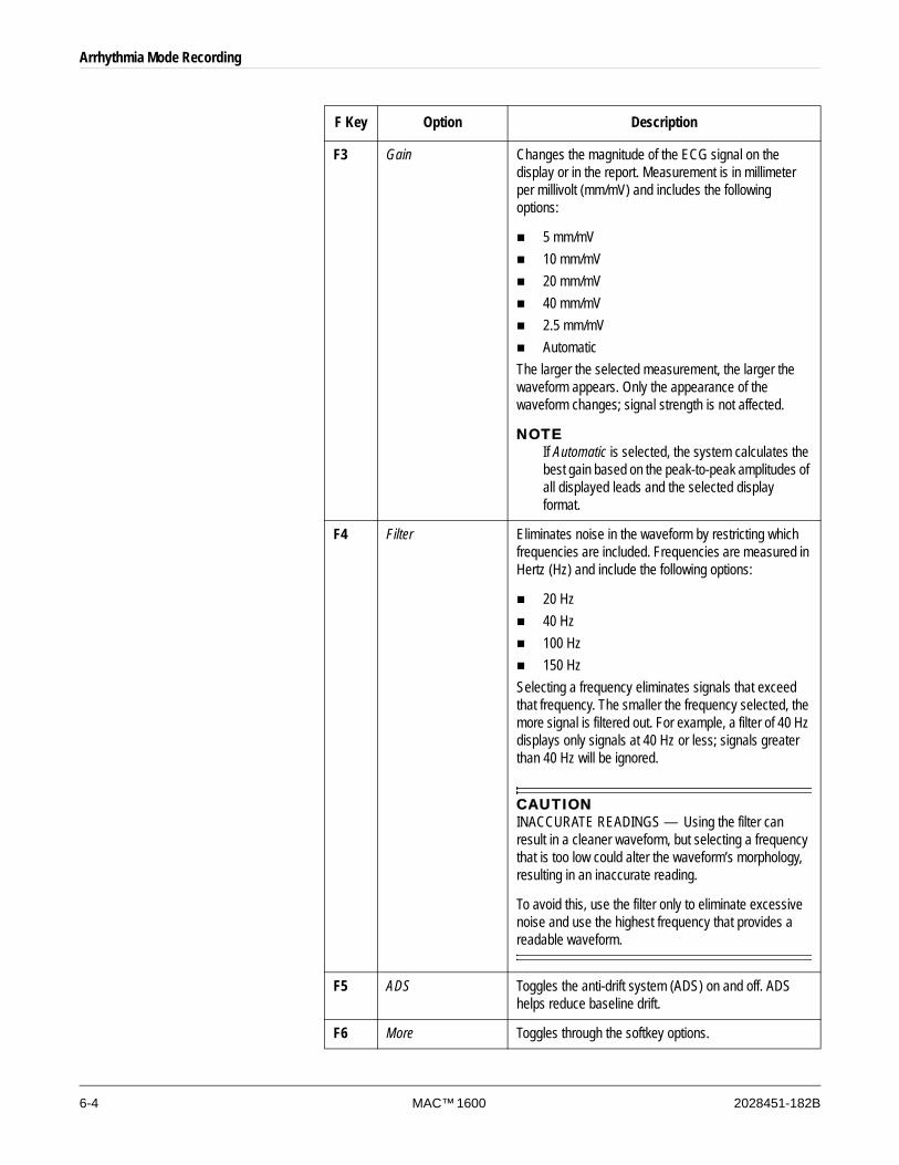
6-4 MAC™ 1600 2028451-182B
Arrhythmia Mode Recording
F3 Gain Changes the magnitude of the ECG signal on the display or in the report. Measurement is in millimeter per millivolt (mm/mV) and includes the following options:
5 mm/mV10 mm/mV20 mm/mV40 mm/mV2.5 mm/mVAutomatic
The larger the selected measurement, the larger the waveform appears. Only the appearance of the waveform changes; signal strength is not affected.
NOTEIf Automatic is selected, the system calculates the best gain based on the peak-to-peak amplitudes of all displayed leads and the selected display format.
F4 Filter Eliminates noise in the waveform by restricting which frequencies are included. Frequencies are measured in Hertz (Hz) and include the following options:
20 Hz40 Hz100 Hz150 Hz
Selecting a frequency eliminates signals that exceed that frequency. The smaller the frequency selected, the more signal is filtered out. For example, a filter of 40 Hz displays only signals at 40 Hz or less; signals greater than 40 Hz will be ignored.
CAUTIONINACCURATE READINGS — Using the filter can result in a cleaner waveform, but selecting a frequency that is too low could alter the waveform’s morphology, resulting in an inaccurate reading.
To avoid this, use the filter only to eliminate excessive noise and use the highest frequency that provides a readable waveform.
F5 ADS Toggles the anti-drift system (ADS) on and off. ADS helps reduce baseline drift.
F6 More Toggles through the softkey options.
F Key Option Description
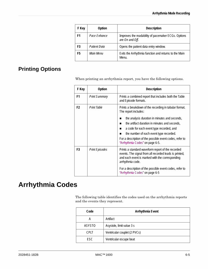
Arrhythmia Mode Recording
2028451-182B MAC™ 1600 6-5
Printing OptionsWhen printing an arrhythmia report, you have the following options.
Arrhythmia CodesThe following table identifies the codes used on the arrhythmia reports and the events they represent.
F1 Pace Enhance Improves the readability of pacemaker ECGs. Options are On and Off.
F3 Patient Data Opens the patient data entry window.
F5 Main Menu Exits the Arrhythmia function and returns to the Main Menu.
F Key Option Description
F Key Option Description
F1 Print Summary Prints a combined report that includes both the Table and Episode formats.
F2 Print Table Prints a breakdown of the recording in tabular format. The report includes:
the analysis duration in minutes and seconds, the artifact duration in minutes and seconds, a code for each event type recorded, andthe number of each event type recorded.
For a description of the possible event codes, refer to “Arrhythmia Codes” on page 6-5.
F3 Print Episodes Prints a standard waveform report of the recorded events. The signal from all recorded leads is printed, and each event is marked with the corresponding arrhythmia code.
For a description of the possible event codes, refer to “Arrhythmia Codes” on page 6-5
Code Arrhythmia Event
A Artifact
ASYSTO Asystole, limit value 3 s
CPLT Ventricular couplet (2 PVCs)
ESC Ventricular escape beat
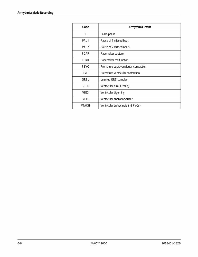
6-6 MAC™ 1600 2028451-182B
Arrhythmia Mode Recording
L Learn phase
PAU1 Pause of 1 missed beat
PAU2 Pause of 2 missed beats
PCAP Pacemaker capture
PERR Pacemaker malfunction
PSVC Premature supraventricular contraction
PVC Premature ventricular contraction
QRSL Learned QRS complex
RUN Ventricular run (3 PVCs)
VBIG Ventricular bigeminy
VFIB Ventricular fibrillation/flutter
VTACH Ventricular tachycardia (>3 PVCs)
Code Arrhythmia Event

2028451-182B MAC™ 1600 7-1
7 Stress Testing
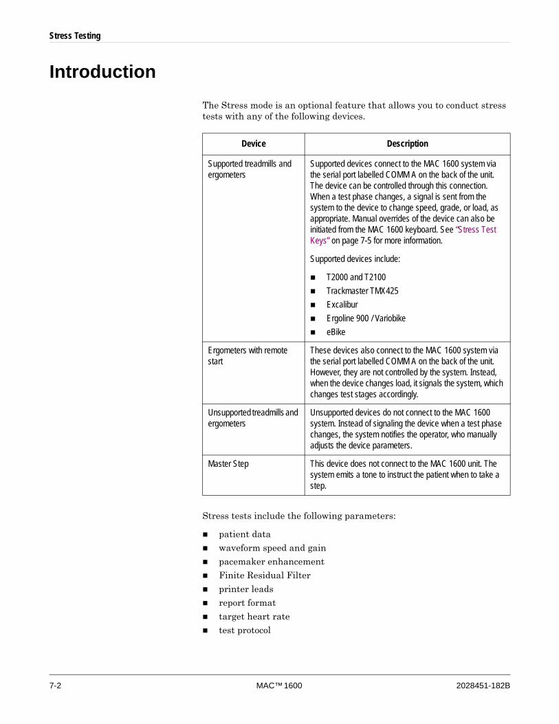
7-2 MAC™ 1600 2028451-182B
Stress Testing
IntroductionThe Stress mode is an optional feature that allows you to conduct stress tests with any of the following devices.
Stress tests include the following parameters:
patient data
waveform speed and gain
pacemaker enhancement
Finite Residual Filter
printer leads
report format
target heart rate
test protocol
Device Description
Supported treadmills and ergometers
Supported devices connect to the MAC 1600 system via the serial port labelled COMM A on the back of the unit. The device can be controlled through this connection. When a test phase changes, a signal is sent from the system to the device to change speed, grade, or load, as appropriate. Manual overrides of the device can also be initiated from the MAC 1600 keyboard. See “Stress Test Keys” on page 7-5 for more information.
Supported devices include:
T2000 and T2100Trackmaster TMX425ExcaliburErgoline 900 / VariobikeeBike
Ergometers with remote start
These devices also connect to the MAC 1600 system via the serial port labelled COMM A on the back of the unit. However, they are not controlled by the system. Instead, when the device changes load, it signals the system, which changes test stages accordingly.
Unsupported treadmills and ergometers
Unsupported devices do not connect to the MAC 1600 system. Instead of signaling the device when a test phase changes, the system notifies the operator, who manually adjusts the device parameters.
Master Step This device does not connect to the MAC 1600 unit. The system emits a tone to instruct the patient when to take a step.
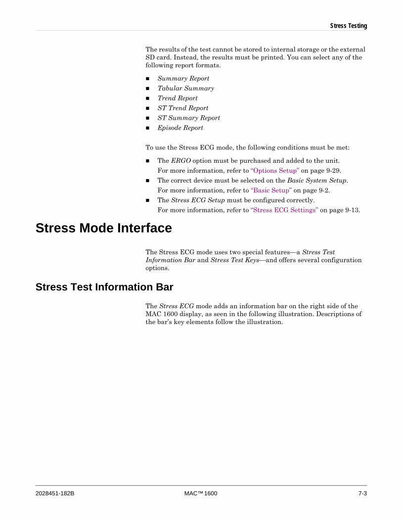
Stress Testing
2028451-182B MAC™ 1600 7-3
The results of the test cannot be stored to internal storage or the external SD card. Instead, the results must be printed. You can select any of the following report formats.
Summary Report
Tabular Summary
Trend Report
ST Trend Report
ST Summary Report
Episode Report
To use the Stress ECG mode, the following conditions must be met:
The ERGO option must be purchased and added to the unit.
For more information, refer to “Options Setup” on page 9-29.
The correct device must be selected on the Basic System Setup.
For more information, refer to “Basic Setup” on page 9-2.
The Stress ECG Setup must be configured correctly.
For more information, refer to “Stress ECG Settings” on page 9-13.
Stress Mode InterfaceThe Stress ECG mode uses two special features—a Stress Test Information Bar and Stress Test Keys—and offers several configuration options.
Stress Test Information BarThe Stress ECG mode adds an information bar on the right side of the MAC 1600 display, as seen in the following illustration. Descriptions of the bar’s key elements follow the illustration.
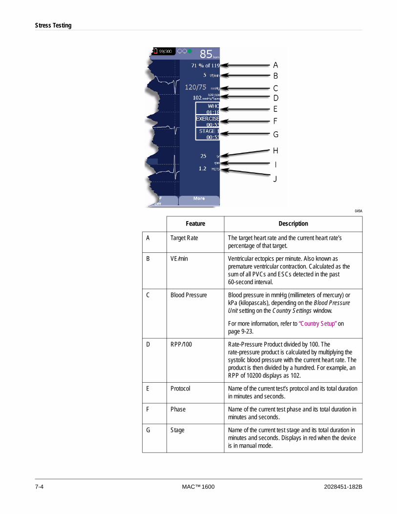
7-4 MAC™ 1600 2028451-182B
Stress Testing
049A
Feature Description
A Target Rate The target heart rate and the current heart rate’s percentage of that target.
B VE/min Ventricular ectopics per minute. Also known as premature ventricular contraction. Calculated as the sum of all PVCs and ESCs detected in the past 60-second interval.
C Blood Pressure Blood pressure in mmHg (millimeters of mercury) or kPa (kilopascals), depending on the Blood Pressure Unit setting on the Country Settings window.
For more information, refer to “Country Setup” on page 9-23.
D RPP/100 Rate-Pressure Product divided by 100. The rate-pressure product is calculated by multiplying the systolic blood pressure with the current heart rate. The product is then divided by a hundred. For example, an RPP of 10200 displays as 102.
E Protocol Name of the current test’s protocol and its total duration in minutes and seconds.
F Phase Name of the current test phase and its total duration in minutes and seconds.
G Stage Name of the current test stage and its total duration in minutes and seconds. Displays in red when the device is in manual mode.
Stress Testing
2028451-182B MAC™ 1600 7-5
Stress Test KeysThe Stress ECG mode makes use of the double row of stress keys near the top of the MAC 1600 keyboard, as seen in the following illustration. Your keyboard may differ slightly from that shown.
001
H Speed/Load Speed of the treadmill or load of the ergometer. For speed, may be displayed as km/h (kilometers per hour) or mph (miles per hour) depending on the Speed Unit selected on the Country Settings window. For load, displayed in watts.
For more information, refer to “Country Setup” on page 9-23.
I Grade/RPM The grade for a treadmill, in percent, or the revolutions per minute for an ergometer.
J METS Metabolic equivalent of the current exercise level.
Feature Description
Key Description
A Pretest Initiates the test.
B Exercise Advances to the EXERCISE phase or to the next stage within the selected phase.
C Recovery Advances to the RECOVERY phase or to the next stage within the selected phase.
D Test end Ends the current test. When a confirmation message appears on screen, press the corresponding function key.
E Hold stage Maintains the current test stage. That is, it stops automatic stage sequencing. Press again to return to stage sequencing.
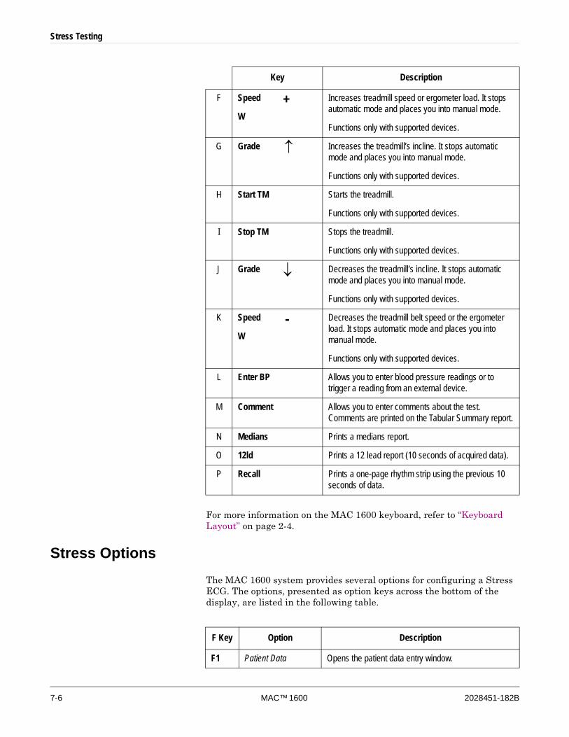
7-6 MAC™ 1600 2028451-182B
Stress Testing
For more information on the MAC 1600 keyboard, refer to “Keyboard Layout” on page 2-4.
Stress OptionsThe MAC 1600 system provides several options for configuring a Stress ECG. The options, presented as option keys across the bottom of the display, are listed in the following table.
F Speed
W+ Increases treadmill speed or ergometer load. It stops
automatic mode and places you into manual mode.
Functions only with supported devices.
G Grade ↑ Increases the treadmill’s incline. It stops automatic mode and places you into manual mode.
Functions only with supported devices.
H Start TM Starts the treadmill.
Functions only with supported devices.
I Stop TM Stops the treadmill.
Functions only with supported devices.
J Grade ↓ Decreases the treadmill’s incline. It stops automatic mode and places you into manual mode.
Functions only with supported devices.
K Speed
W - Decreases the treadmill belt speed or the ergometer
load. It stops automatic mode and places you into manual mode.
Functions only with supported devices.
L Enter BP Allows you to enter blood pressure readings or to trigger a reading from an external device.
M Comment Allows you to enter comments about the test. Comments are printed on the Tabular Summary report.
N Medians Prints a medians report.
O 12ld Prints a 12 lead report (10 seconds of acquired data).
P Recall Prints a one-page rhythm strip using the previous 10 seconds of data.
Key Description
F Key Option Description
F1 Patient Data Opens the patient data entry window.
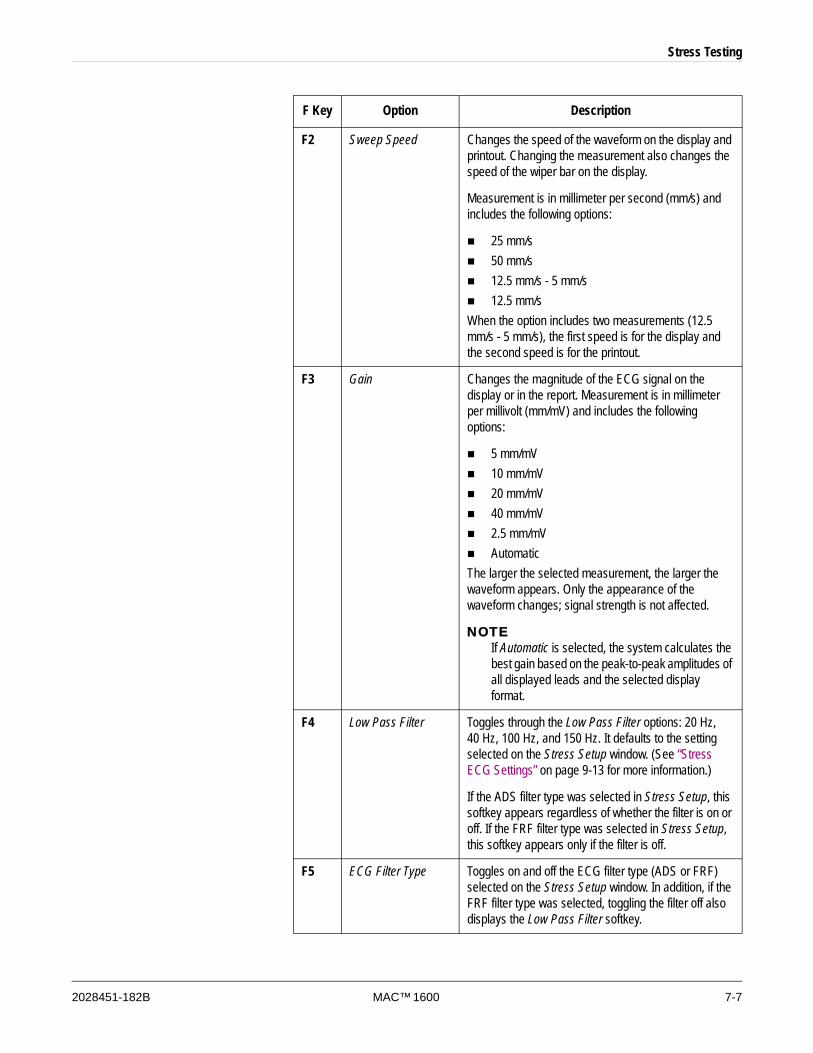
Stress Testing
2028451-182B MAC™ 1600 7-7
F2 Sweep Speed Changes the speed of the waveform on the display and printout. Changing the measurement also changes the speed of the wiper bar on the display.
Measurement is in millimeter per second (mm/s) and includes the following options:
25 mm/s50 mm/s12.5 mm/s - 5 mm/s12.5 mm/s
When the option includes two measurements (12.5 mm/s - 5 mm/s), the first speed is for the display and the second speed is for the printout.
F3 Gain Changes the magnitude of the ECG signal on the display or in the report. Measurement is in millimeter per millivolt (mm/mV) and includes the following options:
5 mm/mV10 mm/mV20 mm/mV40 mm/mV2.5 mm/mVAutomatic
The larger the selected measurement, the larger the waveform appears. Only the appearance of the waveform changes; signal strength is not affected.
NOTEIf Automatic is selected, the system calculates the best gain based on the peak-to-peak amplitudes of all displayed leads and the selected display format.
F4 Low Pass Filter Toggles through the Low Pass Filter options: 20 Hz, 40 Hz, 100 Hz, and 150 Hz. It defaults to the setting selected on the Stress Setup window. (See “Stress ECG Settings” on page 9-13 for more information.)
If the ADS filter type was selected in Stress Setup, this softkey appears regardless of whether the filter is on or off. If the FRF filter type was selected in Stress Setup, this softkey appears only if the filter is off.
F5 ECG Filter Type Toggles on and off the ECG filter type (ADS or FRF) selected on the Stress Setup window. In addition, if the FRF filter type was selected, toggling the filter off also displays the Low Pass Filter softkey.
F Key Option Description

7-8 MAC™ 1600 2028451-182B
Stress Testing
Conducting Stress TestsThere are two basic processes for conducting a stress test:
Conducting a stress test with a treadmill or ergometer
Conducting a stress test with a Master’s Step device
Each process is described in this section. For information on the Stress Mode interface, refer to “Stress Mode Interface” on page 7-3.
Conducting a Stress Test with a Treadmill or ErgometerUse the following instructions to conduct a stress test with a treadmill or ergometer. The process is essentially identical for all devices with only minor differences between supported devices, unsupported devices, and
F6 More Toggles between the first, second, and third rows of options.
F1 Pace Enhance Increases the readability of pacemaker ECGs. Options are On and Off.
F2 Printer Leads Selects which leads to include in the printout. Options are:
First SixSecond SixRhythm Six12
Used only when conducting rhythm ECGs. Refer to “Generating a Rhythm Report (Manual Recording)” on page 5-7 for more information.
F3 Select Protocol Selects a predefined set of test criteria. For more information, refer to “Editing Stress Protocols” on page 9-16.
F4 Report Format Selects the components and episodes to include in the report. Allows you to override the defaults set on the Stress ECG Setup window. For more information, refer to “Stress ECG Settings” on page 9-13.
F5 Target HR Enter the maximum heart rate calculated for the patient based on weight, sex, age, and condition. The MAC 1600 monitors the heart rate against this target.
F5 Main Menu Exits the Stress ECG function and returns to the Main Menu.
F Key Option Description
Stress Testing
2028451-182B MAC™ 1600 7-9
ergometers with remote start. Deviations for specific devices are noted where appropriate.
DANGERPATIENT INJURY — When on a moving treadmill, a patient could fall and sustain an injury.
To minimize the possibility of a falling caused by the belt’s sudden movement, have the patient step onto the belt only after it begins moving.
When conducting stress tests on a supported treadmill, press the Stop TM button twice to immediately stop the belt in the case of an emergency (for example, if the patient stumbles or falls while the belt is moving).
1. Prepare the patient as described in Chapter 3.
2. From the Main Menu, press F3 to select the Stress ECG option.
The Enter Patient Data window opens.
3. Enter patient data as described in Chapter 4.
4. Adjust the stress options as necessary:
This includes the speed and gain, finite residual filter, pacemaker enhancement, printer leads, test protocol, report format, and target heart rate. For more information on setting these options, refer to “Stress Options” on page 7-6
5. Record a preliminary ECG.
This may be a seated, standing, supine, or hyperventilating ECG, depending on the requirements of the selected protocol.
6. Begin the pretest phase.
a. Have the patient get on the device.
b. Press the Pretest key.
c. Allow the patient to warm up before beginning the exercise phase of the test.
NOTEOn supported treadmills, press Start TM to start the belt.
7. When the patient is ready to begin the stress test, press the Exercise key.
During the test, you can use the stress keys to hold the current stage, enter blood pressure, add a comment, change the displayed leads, and toggle the finite residual filter. With supported devices, the stress keys can also be used to adjust the device’s speed, grade, or load. With unsupported devices, the device must be adjusted manually at the device itself.

7-10 MAC™ 1600 2028451-182B
Stress Testing
For more information on making these adjustments, refer to “Stress Test Keys” on page 7-5.
8. When the exerecise phase is complete, press the Recovery key to begin the recovery phase of the test.
NOTEWhen using an ergometer with remote start, you do not need to press the Recovery key because the recovery phase begins automatically at the end of the last stage. You can, however, press the Recovery key to begin the recovery phase before the last stage ends.
On supported treadmills, the belt begins to slow and the grade drops to 0%. On supported ergometers, the load begins to lighten. On unsupported treadmills and ergometers, these adjustments must be made manually.
Continue to monitor the patient and record the ECG until the device stops.
9. When the recovery phase is over, press the Test End key.
The menu options at the bottom of the screen change to Confirm Test End and Continue Test. Do one of the following:
To return to the test, press the F2 key (Continue Test).
The previous menu options return. Continue to record the ECG as needed. When you are done, repeat this step.
To stop the test, press the F1 key (Confirm Test End).
The menu options change. Continue to step 10.
10. Do any of the following, as necessary.
Press the F1 key (Next Patient) to test another patient.
You are warned that testing another patient will discard the results of the current test. Do one of the following:
Press the F5 key (No) to cancel the change in patients and return to the current test.
You can either print the current test report or change the report formats.
Press the F6 key (Yes) to lose the current test results and test a new patient.
Return to step 3 for the next patient.
Press the F2 key (Print) to print the test’s report.
The report prints with the selected format options.
Press the F3 key (Report Format) to modify the report format.
The Report Format window opens. Select the options you want to include in the report and press the F6 key (Save). You can now print the test’s report.
Stress Testing
2028451-182B MAC™ 1600 7-11
Conducting a Stress Test with a Master’s Step Device Use the following instructions to conduct a stress test with a Master’s Step device, if it is selected in the Stress Setup.
1. Prepare the patient as described in Chapter 3.
2. From the Main Menu, press F3 to select the Stress ECG option.
The Enter Patient Data window opens.
3. Enter patient data as described in Chapter 4.
Be sure you enter accurate information for Date of Birth, Gender, and Weight. The number of steps is determined by these three parameters.
4. Adjust the stress options as necessary:
This includes the speed and gain, finite residual filter, pacemaker enhancement, printer leads, test protocol, report format, and target heart rate. For more information on setting these options, refer to “Stress Options” on page 7-6
5. Record a preliminary ECG.
This may be seated, standing, supine, or hyperventilating, depending on the requirements of the selected protocol.
6. Begin the pretest phase to allow the patient to warm up.
a. Remove the leadwires from the patient, but leave on the electrodes.
This prevents the patient from tripping on the leadwires during the test.
b. Instruct the patient to take a step whenever the MAC 1600 system beeps.
c. Press the Pretest key.
7. Press the Exercise key to begin the test.
The duration of the exercise phase is dependent on the selected protocol: SINGLE is 90 seconds, DOUBLE is 180 seconds, and TRIPLE is 270 seconds.
When the test is complete, the first POST EXER. stage begins and the ELECTR.ON message appears.
8. Reattach the leadwires to the electrodes.
The median report prints at pre-configured intervals during the post exercise stages. When the last post exercise stage is complete, a summary report with trends and tables print.

7-12 MAC™ 1600 2028451-182B
Stress Testing

2028451-182B MAC™ 1600 8-1
8 Managing Internal Storage
8-2 MAC™ 1600 2028451-182B
Managing Internal Storage
IntroductionThe File Manager provides an interface to the system’s optional internal storage. It provides the tools to:
import records from an external source,
print the internal storage directory,
search stored records,
edit a record’s patient data,
delete records,
print records,
transmit records to an external device, and
export records to a secure digital card or shared directory.
Only resting ECGs can be saved to internal storage; arrhythmia and stress ECGs can only be printed.
Resting ECGs can be stored automatically or manually:
To save resting ECG records automatically, set the Auto Store ECG check box on the Resting ECG Settings window.
For more information, refer to “Resting ECG Setup” on page 9-6.
To save resting ECG records manually, press F3 (Save) after the resting ECG has been acquired.
For more information, refer to “Post-Acquisition Options” on page 5-6.
To enable internal storage, the M100 Internal Storage for 100 ECGs option must be enabled.
For information on enabling the internal storage option, refer to “Options Setup” on page 9-29.
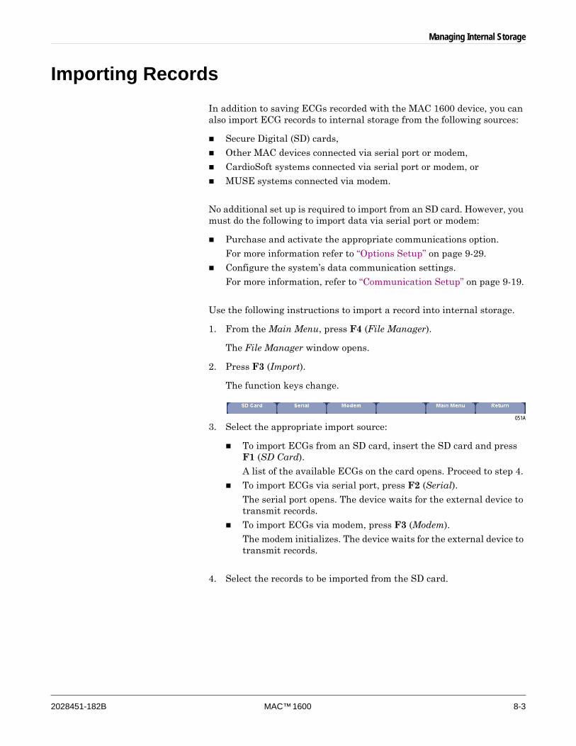
Managing Internal Storage
2028451-182B MAC™ 1600 8-3
Importing Records In addition to saving ECGs recorded with the MAC 1600 device, you can also import ECG records to internal storage from the following sources:
Secure Digital (SD) cards,
Other MAC devices connected via serial port or modem,
CardioSoft systems connected via serial port or modem, or
MUSE systems connected via modem.
No additional set up is required to import from an SD card. However, you must do the following to import data via serial port or modem:
Purchase and activate the appropriate communications option.
For more information refer to “Options Setup” on page 9-29.
Configure the system’s data communication settings.
For more information, refer to “Communication Setup” on page 9-19.
Use the following instructions to import a record into internal storage.
1. From the Main Menu, press F4 (File Manager).
The File Manager window opens.
2. Press F3 (Import).
The function keys change.
051A
3. Select the appropriate import source:
To import ECGs from an SD card, insert the SD card and press F1 (SD Card).
A list of the available ECGs on the card opens. Proceed to step 4.
To import ECGs via serial port, press F2 (Serial).
The serial port opens. The device waits for the external device to transmit records.
To import ECGs via modem, press F3 (Modem).
The modem initializes. The device waits for the external device to transmit records.
4. Select the records to be imported from the SD card.

8-4 MAC™ 1600 2028451-182B
Managing Internal Storage
5. When the correct records are selected, press F1 (Import).
The selected records are imported from the SD card into internal storage.
NOTEImported records have a Sent status of Recv and cannot be edited, transmitted, or exported.
Printing the File Manager DirectoryUse the following instructions to print the directory of ECGs stored in internal memory.
1. From the Main Menu, press F4 (File Manager).
The File Manager window opens.
2. Press F4 (Print Directory).
The directory prints on the MAC 1600 writer.
Finding RecordsThe File Manager may have up to 100 records to manage, making it difficult to find a specific record. To help you locate a record or a group of records, use the following instructions.
1. From the Main Menu, press F4 (File Manager).
The File Manager window opens.
2. Press F5 (Search).
The Enter Search Criteria window opens.
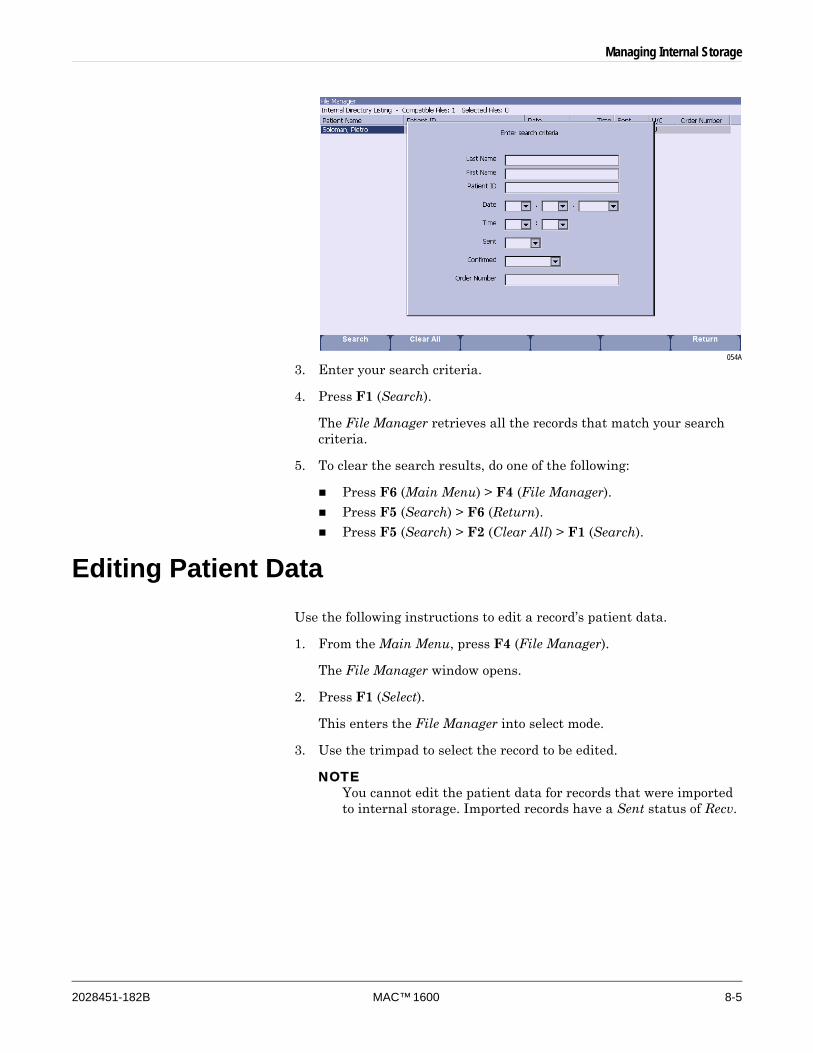
Managing Internal Storage
2028451-182B MAC™ 1600 8-5
054A
3. Enter your search criteria.
4. Press F1 (Search).
The File Manager retrieves all the records that match your search criteria.
5. To clear the search results, do one of the following:
Press F6 (Main Menu) > F4 (File Manager).
Press F5 (Search) > F6 (Return).
Press F5 (Search) > F2 (Clear All) > F1 (Search).
Editing Patient DataUse the following instructions to edit a record’s patient data.
1. From the Main Menu, press F4 (File Manager).
The File Manager window opens.
2. Press F1 (Select).
This enters the File Manager into select mode.
3. Use the trimpad to select the record to be edited.
NOTEYou cannot edit the patient data for records that were imported to internal storage. Imported records have a Sent status of Recv.
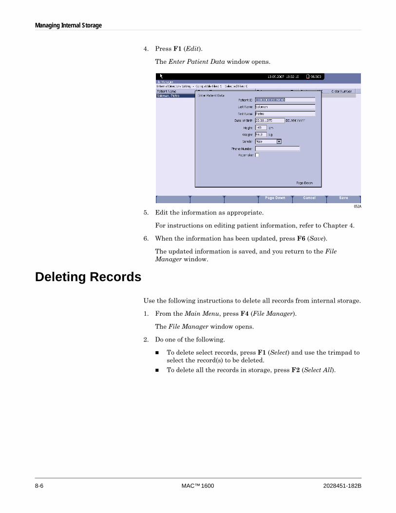
8-6 MAC™ 1600 2028451-182B
Managing Internal Storage
4. Press F1 (Edit).
The Enter Patient Data window opens.
052A
5. Edit the information as appropriate.
For instructions on editing patient information, refer to Chapter 4.
6. When the information has been updated, press F6 (Save).
The updated information is saved, and you return to the File Manager window.
Deleting RecordsUse the following instructions to delete all records from internal storage.
1. From the Main Menu, press F4 (File Manager).
The File Manager window opens.
2. Do one of the following.
To delete select records, press F1 (Select) and use the trimpad to select the record(s) to be deleted.
To delete all the records in storage, press F2 (Select All).
Managing Internal Storage
2028451-182B MAC™ 1600 8-7
3. Press F2 (Delete).
A window opens and prompts you confirm that you want to delete the selected record(s).
4. Do one of the following:
To cancel the deletion, press F5 (No).
To delete the record(s), press F6 (Yes).
Printing RecordsUse the following instructions to print records.
1. From the Main Menu, press F4 (File Manager).
The File Manager window opens.
2. Do one of the following.
To print select records, press F1 (Select) and use the trimpad to select the record(s) to be printed.
To print all the records in storage, press F2 (Select All).
3. Press F3 (Print).
The selected records are printed on the MAC 1600 writer.
Transmitting RecordsUse the following instructions to transmit records from internal storage to an external device.
Before transmitting a record, you must do the following:
Purchase and activate a communication option.
Refer to “Options Setup” on page 9-29 for more information.
Configure data communications.
Refer to “Communication Setup” on page 9-19 for more information.
Connect the MAC 1600 unit to the communication device.
For an external modem, see the MAC 1600 Field Service Manual.
For a LAN connection to a MUSE system, see the LAN Option for MAC Series Installation and Troubleshooting Guide.
For a LAN connection to a CardioSoft system, see “Connecting to a LAN” on page 2-10.

8-8 MAC™ 1600 2028451-182B
Managing Internal Storage
1. From the Main Menu, press F4 (File Manager).
The File Manager window opens.
2. Do one of the following.
To transmit select records, press F1 (Select) and select the record(s) to be transmitted.
NOTEYou cannot transmit records that were imported to internal storage. Imported records have a Sent status of Recv.
To transmit all the records in storage, press F2 (Select All).
3. Press F4 (Transmit).
One of two things happens, depending on the number of locations defined in Communications Setup.
If only one location is defined, the files are transmitted to the default location.
If multiple locations are defined, a window listing the locations opens. Select the correct location and press F6 (OK).
Exporting RecordsUse the following instructions to export records from internal storage to a Secure Digital card or to a shared directory.
NOTEIf exporting to an SD card, bear in mind that data access speeds may vary depending on the SD card capacity and manufacturer. This may affect the time required to read or write ECG records and other information to the SD card. GE recommends the use of a 128 MB, 256 MB or 512 MB card manufactured by SanDisk
No additional setup is required to export data to an SD card. However, before using these instructions to export to a shared directory, you must do the following:
Purchase and activate the LAN to CardioSoft (LANC) option.
Refer to “Options Setup” on page 9-29 for details.
Define the shared directory settings on Communications Setup.
Refer to “Communication Setup” on page 9-19 for details.

Managing Internal Storage
2028451-182B MAC™ 1600 8-9
1. From the Main Menu, press F4 (File Manager).
The File Manager window opens.
2. Select the record(s) to be transmitted.
To transmit select records, press F1 (Select) and use the trimpad to select the records to be exported.
NOTEYou cannot export records that were imported to internal storage. Imported records have a Sent status of Recv.
To transmit all records in storage, press F2 (Select All).
3. If you are exporting to an SD card, insert the card into the MAC 1600 SD Card slot.
Make sure the card has sufficient free space for the selected records and that it is not write protected.
4. Press F5 (Export).
One of two things happens.
If a shared directory was defined, a window opens for you to select the destination.
Skip to step 5.
If a shared directory was not defined, the selected records are exported to the SD card.
A window opens to inform you of the export’s progress. The window closes when the export is complete.
5. Do one of the following:
To export to the SD card, select SD Card in the window.
To export to the shared directory, select Shared Directory in the window.
6. Press F6 (OK).
The selected records are exported to the selected destination. A window opens to inform you of the export’s progress. The window closes when the export is complete.

8-10 MAC™ 1600 2028451-182B
Managing Internal Storage
NOTEWhen exporting to a shared directory, the MAC 1600 device logs on to the directory with the user name and password defined on the Communications Setup window. If either of those values are incorrect, a window will open and prompt you to log in. If this happens, press the ESC key to close the prompt, correct the user name and password on the Communications Setup window, and repeat the export process.

2028451-182B MAC™ 1600 9-1
9 System Configuration
9-2 MAC™ 1600 2028451-182B
System Configuration
IntroductionSystem Configuration provides access to functions that allow you to customize the MAC 1600 settings and to utilities to help manage those settings. This chapter describes the settings managed by each function and the process followed by each utility.
CAUTIONPOTENTIAL DATA LOSS — After making configuration changes, you MUST return to the MAC 1600 Main Menu to ensure the changes are saved.
Setup FunctionsSetup functions fall into the following categories:
Basic system settings
Resting ECG settings
Arrhythmia settings
Stress ECG settings
Communication settings
Country settings
Print settings
Patient settings
User settings
Options
Service settings
Date and time
Depending on which system options have been activated, some of these functions may not be available on your device.
Basic SetupThe Basic Setup function allows you to define the following information:
Institutional identification
Default physicians
System settings
Stress test device (if the ERGO stress test option is activated)
System security
Time servers
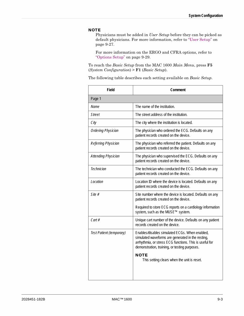
System Configuration
2028451-182B MAC™ 1600 9-3
NOTEPhysicians must be added in User Setup before they can be picked as default physicians. For more information, refer to “User Setup” on page 9-27.
For more information on the ERGO and CFRA options, refer to “Options Setup” on page 9-29.
To reach the Basic Setup from the MAC 1600 Main Menu, press F5 (System Configuration) > F1 (Basic Setup).
The following table describes each setting available on Basic Setup.
Field Comment
Page 1
Name The name of the institution.
Street The street address of the institution.
City The city where the institution is located.
Ordering Physician The physician who ordered the ECG. Defaults on any patient records created on the device.
Referring Physician The physician who referred the patient. Defaults on any patient records created on the device.
Attending Physician The physician who supervised the ECG. Defaults on any patient records created on the device.
Technician The technician who conducted the ECG. Defaults on any patient records created on the device.
Location Location ID where the device is located. Defaults on any patient records created on the device.
Site # Site number where the device is located. Defaults on any patient records created on the device.
Required to store ECG reports on a cardiology information system, such as the MUSE™ system.
Cart # Unique cart number of the device. Defaults on any patient records created on the device.
Test Patient (temporary) Enables/disables simulated ECGs. When enabled, simulated waveforms are generated in the resting, arrhythmia, or stress ECG functions. This is useful for demonstration, training, or testing purposes.
NOTEThis setting clears when the unit is reset.
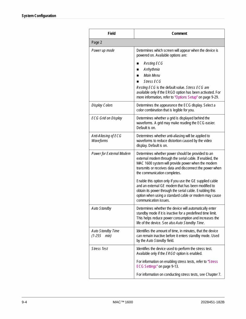
9-4 MAC™ 1600 2028451-182B
System Configuration
Page 2
Power up mode Determines which screen will appear when the device is powered on. Available options are:
Resting ECGArrhythmiaMain MenuStress ECG
Resting ECG is the default value. Stress ECG are available only if the ERGO option has been activated. For more information, refer to “Options Setup” on page 9-29.
Display Colors Determines the appearance the ECG display. Select a color combination that is legible for you.
ECG Grid on Display Determines whether a grid is displayed behind the waveforms. A grid may make reading the ECG easier. Default is on.
Anti-Aliasing of ECG Waveforms
Determines whether anti-aliasing will be applied to waveforms to reduce distortion caused by the video display. Default is on.
Power for External Modem Determines whether power should be provided to an external modem through the serial cable. If enabled, the MAC 1600 system will provide power when the modem transmits or receives data and disconnect the power when the communication completes.
Enable this option only if you use the GE supplied cable and an external GE modem that has been modified to obtain its power through the serial cable. Enabling this option when using a standard cable or modem may cause communication issues.
Auto Standby Determines whether the device will automatically enter standby mode if it is inactive for a predefined time limit. This helps reduce power consumption and increases the life of the device. See also Auto Standby Time.
Auto Standby Time (1-255 min)
Identifies the amount of time, in minutes, that the device can remain inactive before it enters standby mode. Used by the Auto Standby field.
Stress Test Identifies the device used to perform the stress test. Available only if the ERGO option is enabled.
For information on enabling stress tests, refer to “Stress ECG Settings” on page 9-13.
For information on conducting stress tests, see Chapter 7.
Field Comment
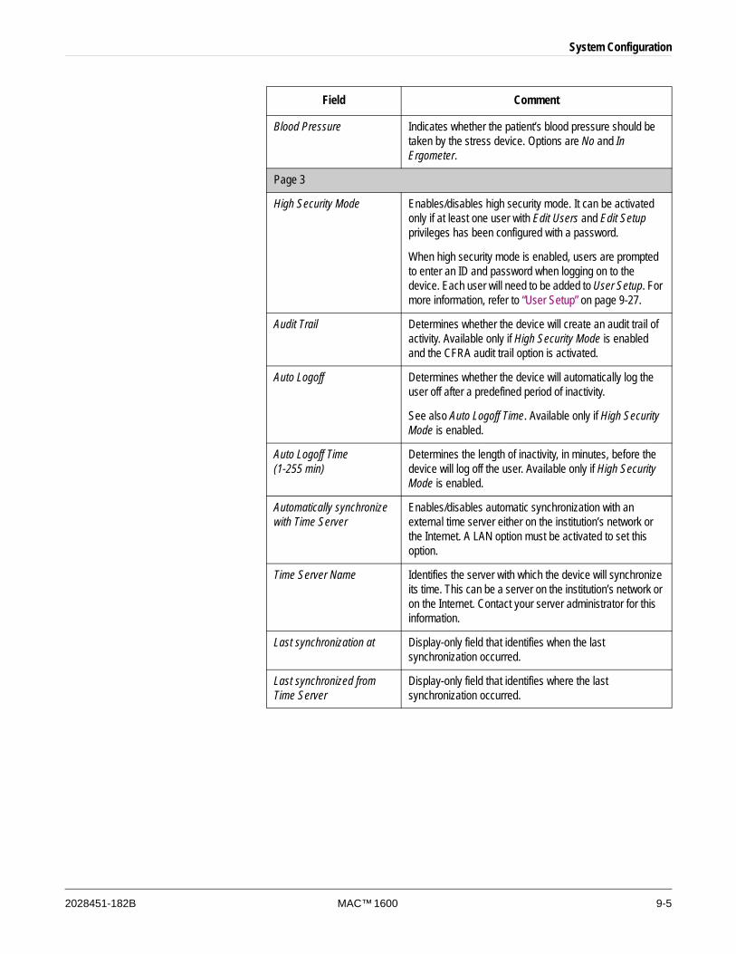
System Configuration
2028451-182B MAC™ 1600 9-5
Blood Pressure Indicates whether the patient’s blood pressure should be taken by the stress device. Options are No and In Ergometer.
Page 3
High Security Mode Enables/disables high security mode. It can be activated only if at least one user with Edit Users and Edit Setup privileges has been configured with a password.
When high security mode is enabled, users are prompted to enter an ID and password when logging on to the device. Each user will need to be added to User Setup. For more information, refer to “User Setup” on page 9-27.
Audit Trail Determines whether the device will create an audit trail of activity. Available only if High Security Mode is enabled and the CFRA audit trail option is activated.
Auto Logoff Determines whether the device will automatically log the user off after a predefined period of inactivity.
See also Auto Logoff Time. Available only if High Security Mode is enabled.
Auto Logoff Time (1-255 min)
Determines the length of inactivity, in minutes, before the device will log off the user. Available only if High Security Mode is enabled.
Automatically synchronize with Time Server
Enables/disables automatic synchronization with an external time server either on the institution’s network or the Internet. A LAN option must be activated to set this option.
Time Server Name Identifies the server with which the device will synchronize its time. This can be a server on the institution’s network or on the Internet. Contact your server administrator for this information.
Last synchronization at Display-only field that identifies when the last synchronization occurred.
Last synchronized from Time Server
Display-only field that identifies where the last synchronization occurred.
Field Comment
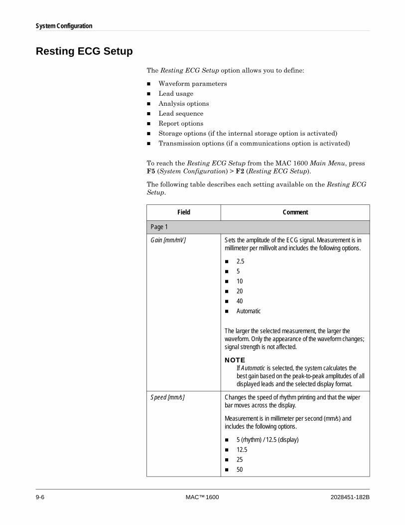
9-6 MAC™ 1600 2028451-182B
System Configuration
Resting ECG SetupThe Resting ECG Setup option allows you to define:
Waveform parameters
Lead usage
Analysis options
Lead sequence
Report options
Storage options (if the internal storage option is activated)
Transmission options (if a communications option is activated)
To reach the Resting ECG Setup from the MAC 1600 Main Menu, press F5 (System Configuration) > F2 (Resting ECG Setup).
The following table describes each setting available on the Resting ECG Setup.
Field Comment
Page 1
Gain [mm/mV] Sets the amplitude of the ECG signal. Measurement is in millimeter per millivolt and includes the following options.
2.5 5 10 20 40Automatic
The larger the selected measurement, the larger the waveform. Only the appearance of the waveform changes; signal strength is not affected.
NOTEIf Automatic is selected, the system calculates the best gain based on the peak-to-peak amplitudes of all displayed leads and the selected display format.
Speed [mm/s] Changes the speed of rhythm printing and that the wiper bar moves across the display.
Measurement is in millimeter per second (mm/s) and includes the following options.
5 (rhythm) / 12.5 (display)12.52550
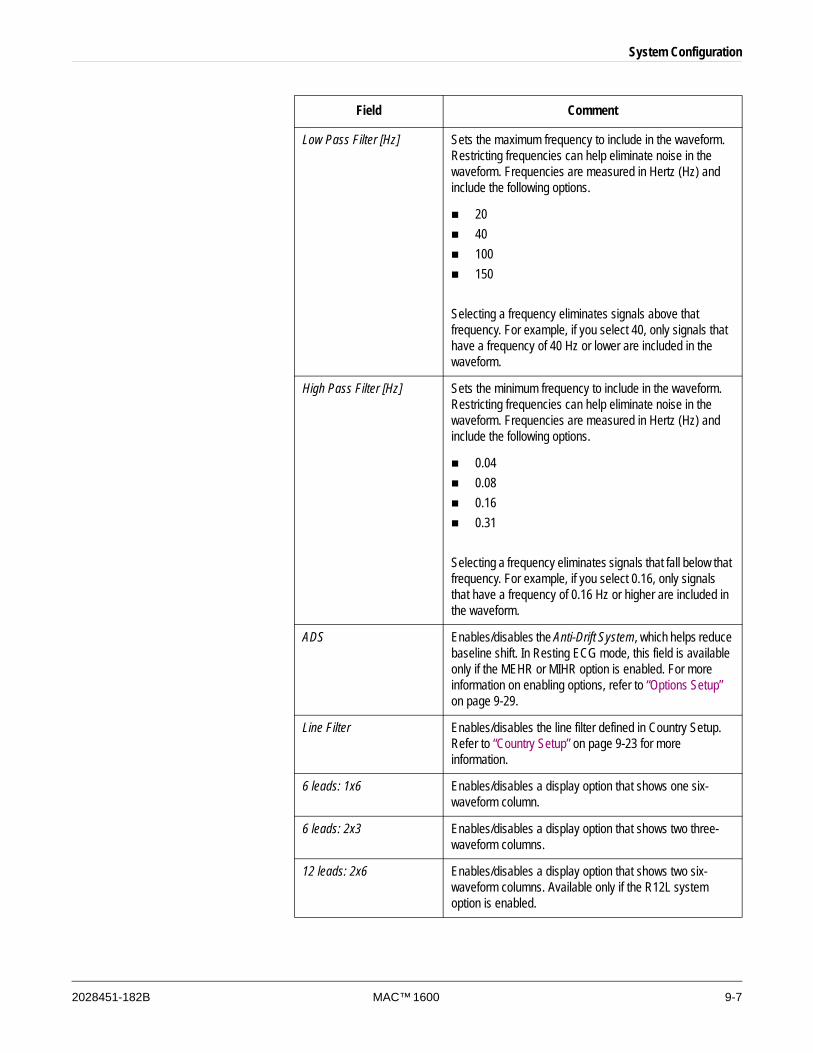
System Configuration
2028451-182B MAC™ 1600 9-7
Low Pass Filter [Hz] Sets the maximum frequency to include in the waveform. Restricting frequencies can help eliminate noise in the waveform. Frequencies are measured in Hertz (Hz) and include the following options.
2040100150
Selecting a frequency eliminates signals above that frequency. For example, if you select 40, only signals that have a frequency of 40 Hz or lower are included in the waveform.
High Pass Filter [Hz] Sets the minimum frequency to include in the waveform. Restricting frequencies can help eliminate noise in the waveform. Frequencies are measured in Hertz (Hz) and include the following options.
0.040.080.160.31
Selecting a frequency eliminates signals that fall below that frequency. For example, if you select 0.16, only signals that have a frequency of 0.16 Hz or higher are included in the waveform.
ADS Enables/disables the Anti-Drift System, which helps reduce baseline shift. In Resting ECG mode, this field is available only if the MEHR or MIHR option is enabled. For more information on enabling options, refer to “Options Setup” on page 9-29.
Line Filter Enables/disables the line filter defined in Country Setup. Refer to “Country Setup” on page 9-23 for more information.
6 leads: 1x6 Enables/disables a display option that shows one six-waveform column.
6 leads: 2x3 Enables/disables a display option that shows two three-waveform columns.
12 leads: 2x6 Enables/disables a display option that shows two six-waveform columns. Available only if the R12L system option is enabled.
Field Comment
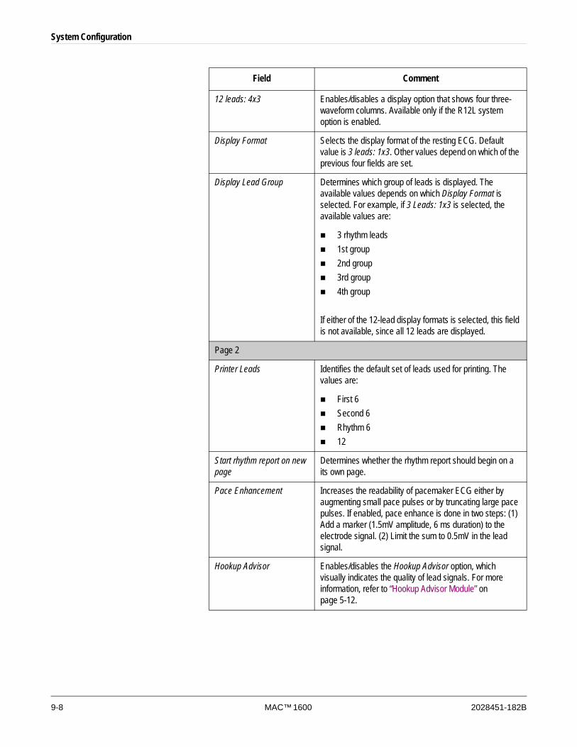
9-8 MAC™ 1600 2028451-182B
System Configuration
12 leads: 4x3 Enables/disables a display option that shows four three-waveform columns. Available only if the R12L system option is enabled.
Display Format Selects the display format of the resting ECG. Default value is 3 leads: 1x3. Other values depend on which of the previous four fields are set.
Display Lead Group Determines which group of leads is displayed. The available values depends on which Display Format is selected. For example, if 3 Leads: 1x3 is selected, the available values are:
3 rhythm leads1st group2nd group3rd group4th group
If either of the 12-lead display formats is selected, this field is not available, since all 12 leads are displayed.
Page 2
Printer Leads Identifies the default set of leads used for printing. The values are:
First 6Second 6Rhythm 612
Start rhythm report on new page
Determines whether the rhythm report should begin on a its own page.
Pace Enhancement Increases the readability of pacemaker ECG either by augmenting small pace pulses or by truncating large pace pulses. If enabled, pace enhance is done in two steps: (1) Add a marker (1.5mV amplitude, 6 ms duration) to the electrode signal. (2) Limit the sum to 0.5mV in the lead signal.
Hookup Advisor Enables/disables the Hookup Advisor option, which visually indicates the quality of lead signals. For more information, refer to “Hookup Advisor Module” on page 5-12.
Field Comment
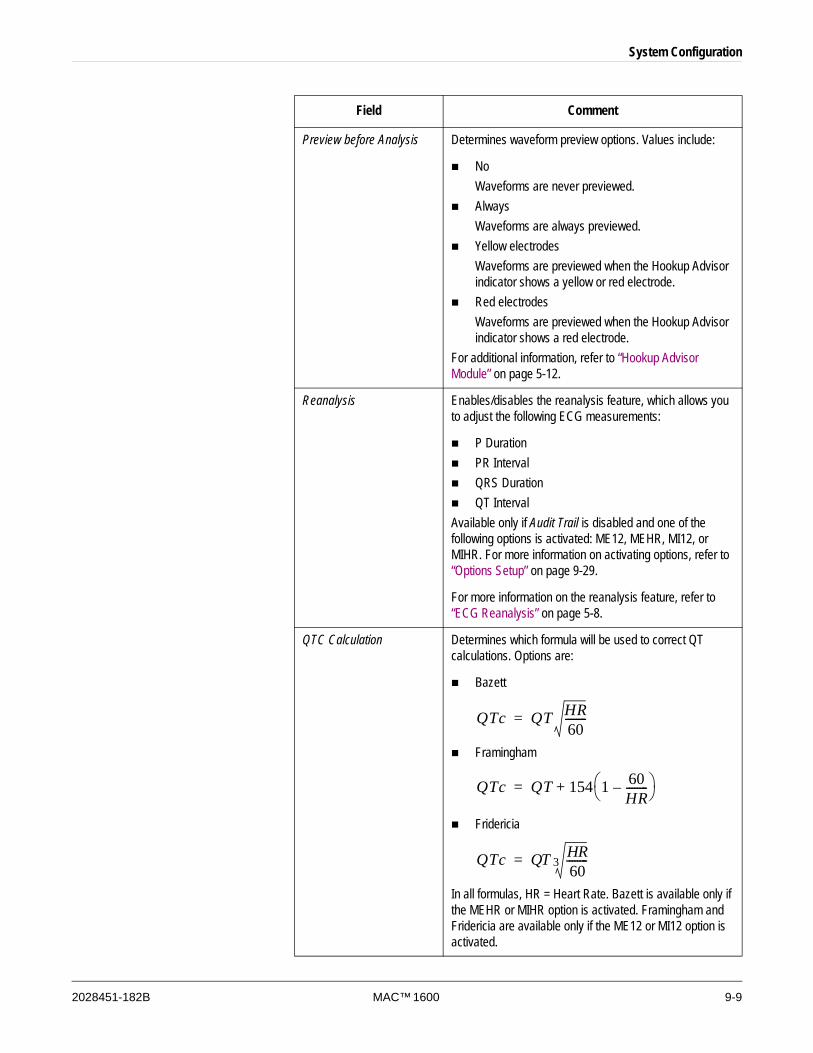
System Configuration
2028451-182B MAC™ 1600 9-9
Preview before Analysis Determines waveform preview options. Values include:
NoWaveforms are never previewed. AlwaysWaveforms are always previewed. Yellow electrodesWaveforms are previewed when the Hookup Advisor indicator shows a yellow or red electrode. Red electrodesWaveforms are previewed when the Hookup Advisor indicator shows a red electrode.
For additional information, refer to “Hookup Advisor Module” on page 5-12.
Reanalysis Enables/disables the reanalysis feature, which allows you to adjust the following ECG measurements:
P DurationPR IntervalQRS DurationQT Interval
Available only if Audit Trail is disabled and one of the following options is activated: ME12, MEHR, MI12, or MIHR. For more information on activating options, refer to “Options Setup” on page 9-29.
For more information on the reanalysis feature, refer to “ECG Reanalysis” on page 5-8.
QTC Calculation Determines which formula will be used to correct QT calculations. Options are:
Bazett
Framingham
Fridericia
In all formulas, HR = Heart Rate. Bazett is available only if the MEHR or MIHR option is activated. Framingham and Fridericia are available only if the ME12 or MI12 option is activated.
Field Comment
QTc QT HR60--------=
QTc QT 154 1 60HR--------–⎝ ⎠
⎛ ⎞+=
QTc QT HR60--------3=
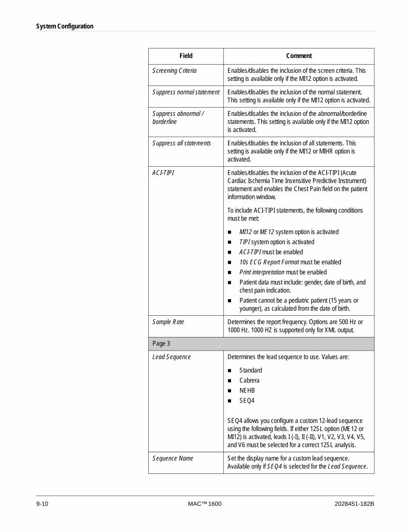
9-10 MAC™ 1600 2028451-182B
System Configuration
Screening Criteria Enables/disables the inclusion of the screen criteria. This setting is available only if the MI12 option is activated.
Suppress normal statement Enables/disables the inclusion of the normal statement. This setting is available only if the MI12 option is activated.
Suppress abnormal / borderline
Enables/disables the inclusion of the abnormal/borderline statements. This setting is available only if the MI12 option is activated.
Suppress all statements Enables/disables the inclusion of all statements. This setting is available only if the MI12 or MIHR option is activated.
ACI-TIPI Enables/disables the inclusion of the ACI-TIPI (Acute Cardiac Ischemia Time Insensitive Predictive Instrument) statement and enables the Chest Pain field on the patient information window.
To include ACI-TIPI statements, the following conditions must be met:
MI12 or ME12 system option is activatedTIPI system option is activatedACI-TIPI must be enabled10s ECG Report Format must be enabledPrint interpretation must be enabledPatient data must include: gender, date of birth, and chest pain indication. Patient cannot be a pediatric patient (15 years or younger), as calculated from the date of birth.
Sample Rate Determines the report frequency. Options are 500 Hz or 1000 Hz. 1000 HZ is supported only for XML output.
Page 3
Lead Sequence Determines the lead sequence to use. Values are:
StandardCabreraNEHBSEQ4
SEQ4 allows you configure a custom 12-lead sequence using the following fields. If either 12SL option (ME12 or MI12) is activated, leads I (-I), II (-II), V1, V2, V3, V4, V5, and V6 must be selected for a correct 12SL analysis.
Sequence Name Set the display name for a custom lead sequence. Available only if SEQ4 is selected for the Lead Sequence.
Field Comment
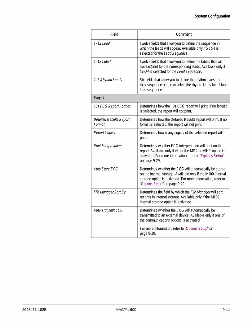
System Configuration
2028451-182B MAC™ 1600 9-11
1–12 Lead Twelve fields that allow you to define the sequence in which the leads will appear. Available only if SEQ4 is selected for the Lead Sequence.
1–12 Label Twelve fields that allow you to define the labels that will appear/print for the corresponding leads. Available only if SEQ4 is selected for the Lead Sequence.
1–6 Rhythm Leads Six fields that allow you to define the rhythm leads and their sequence. You can select the rhythm leads for all four lead sequences.
Page 4
10s ECG Report Format Determines how the 10s ECG report will print. If no format is selected, the report will not print.
Detailed Results Report Format
Determines how the Detailed Results report will print. If no format is selected, the report will not print.
Report Copies Determines how many copies of the selected report will print.
Print Interpretation Determines whether ECG interpretation will print on the report. Available only if either the MI12 or MIHR option is activated. For more information, refer to “Options Setup” on page 9-29.
Auto Store ECG Determines whether the ECG will automatically be stored on the internal storage. Available only if the M100 internal storage option is activated. For more information, refer to “Options Setup” on page 9-29.
File Manager Sort By Determines the field by which the File Manager will sort records in internal storage. Available only if the M100 internal storage option is activated.
Auto Transmit ECG Determines whether the ECG will automatically be transmitted to an external device. Available only if one of the communications options is activated.
For more information, refer to “Options Setup” on page 9-29.
Field Comment
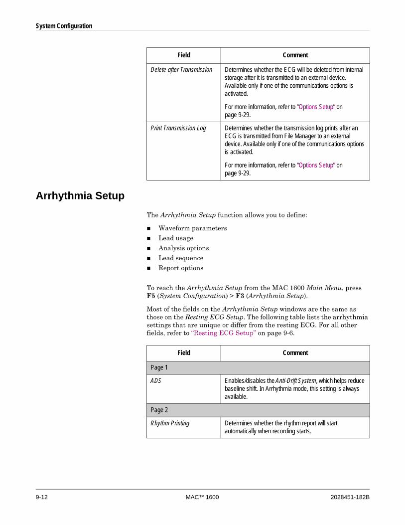
9-12 MAC™ 1600 2028451-182B
System Configuration
Arrhythmia SetupThe Arrhythmia Setup function allows you to define:
Waveform parameters
Lead usage
Analysis options
Lead sequence
Report options
To reach the Arrhythmia Setup from the MAC 1600 Main Menu, press F5 (System Configuration) > F3 (Arrhythmia Setup).
Most of the fields on the Arrhythmia Setup windows are the same as those on the Resting ECG Setup. The following table lists the arrhythmia settings that are unique or differ from the resting ECG. For all other fields, refer to “Resting ECG Setup” on page 9-6.
Delete after Transmission Determines whether the ECG will be deleted from internal storage after it is transmitted to an external device. Available only if one of the communications options is activated.
For more information, refer to “Options Setup” on page 9-29.
Print Transmission Log Determines whether the transmission log prints after an ECG is transmitted from File Manager to an external device. Available only if one of the communications options is activated.
For more information, refer to “Options Setup” on page 9-29.
Field Comment
Field Comment
Page 1
ADS Enables/disables the Anti-Drift System, which helps reduce baseline shift. In Arrhythmia mode, this setting is always available.
Page 2
Rhythm Printing Determines whether the rhythm report will start automatically when recording starts.
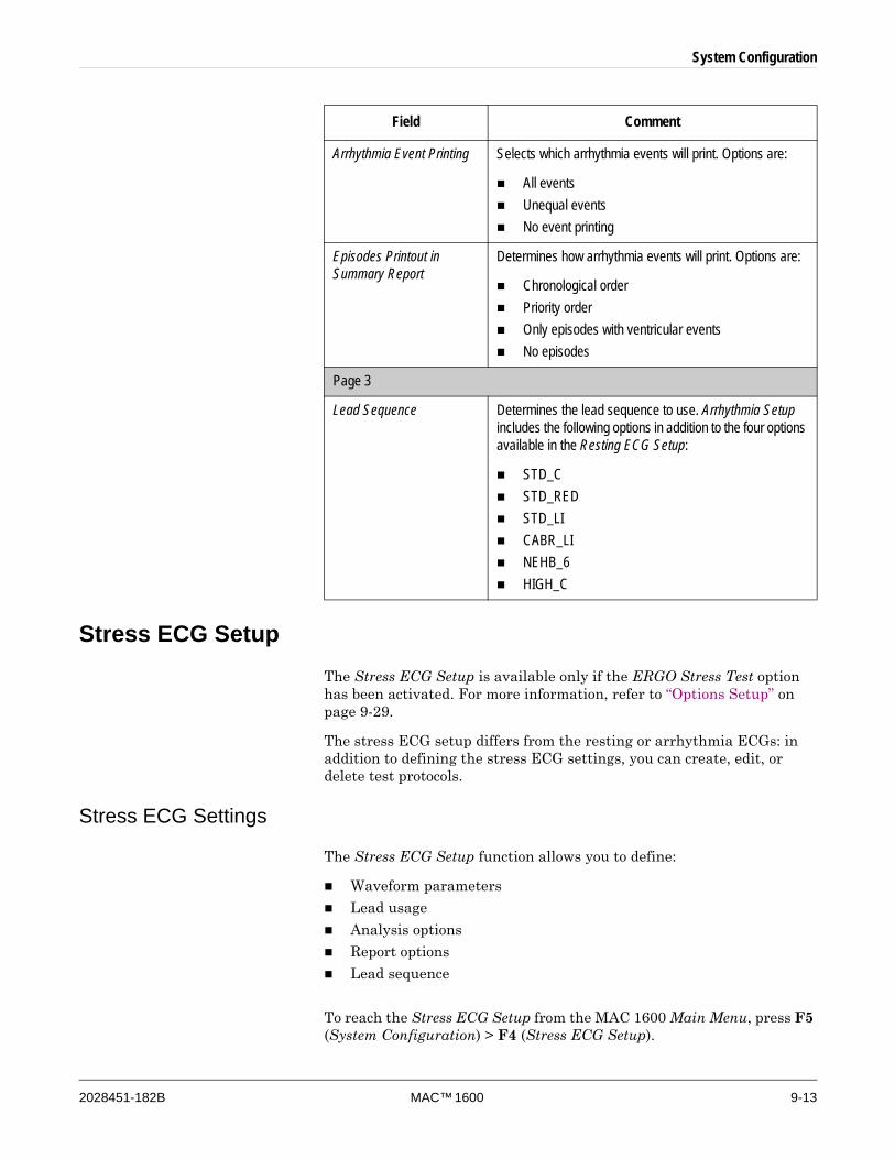
System Configuration
2028451-182B MAC™ 1600 9-13
Stress ECG SetupThe Stress ECG Setup is available only if the ERGO Stress Test option has been activated. For more information, refer to “Options Setup” on page 9-29.
The stress ECG setup differs from the resting or arrhythmia ECGs: in addition to defining the stress ECG settings, you can create, edit, or delete test protocols.
Stress ECG Settings
The Stress ECG Setup function allows you to define:
Waveform parameters
Lead usage
Analysis options
Report options
Lead sequence
To reach the Stress ECG Setup from the MAC 1600 Main Menu, press F5 (System Configuration) > F4 (Stress ECG Setup).
Arrhythmia Event Printing Selects which arrhythmia events will print. Options are:
All eventsUnequal eventsNo event printing
Episodes Printout in Summary Report
Determines how arrhythmia events will print. Options are:
Chronological orderPriority orderOnly episodes with ventricular eventsNo episodes
Page 3
Lead Sequence Determines the lead sequence to use. Arrhythmia Setup includes the following options in addition to the four options available in the Resting ECG Setup:
STD_CSTD_REDSTD_LICABR_LINEHB_6HIGH_C
Field Comment
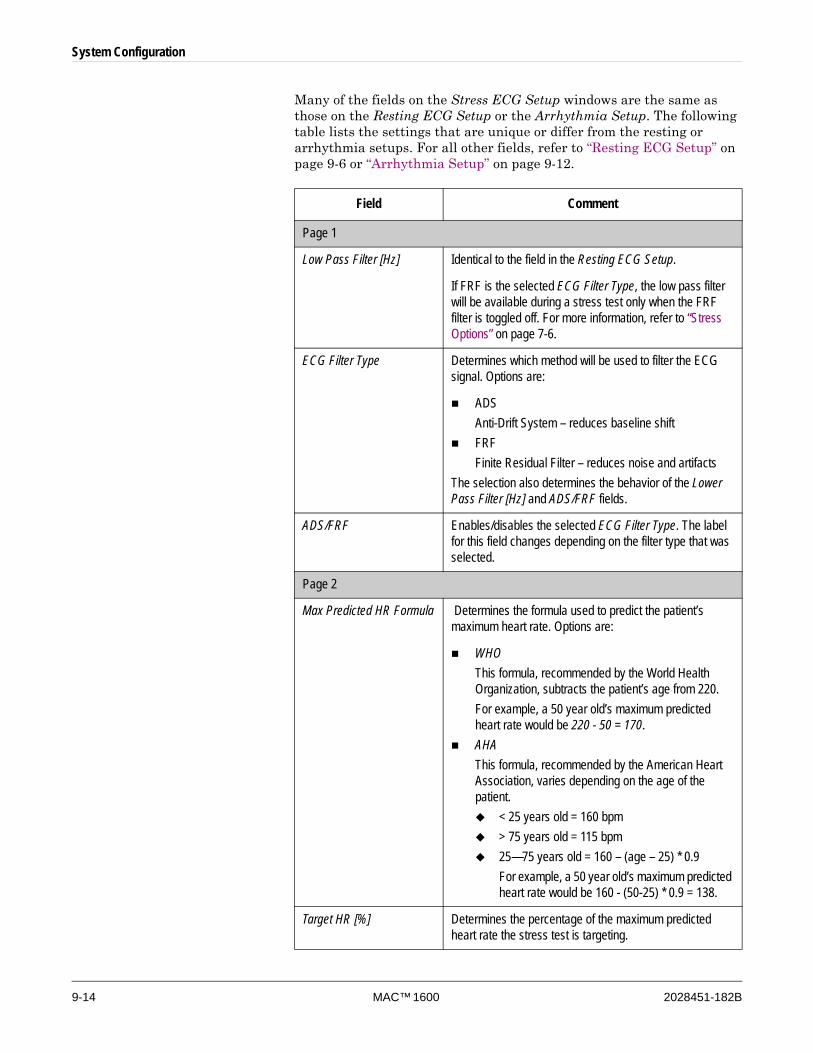
9-14 MAC™ 1600 2028451-182B
System Configuration
Many of the fields on the Stress ECG Setup windows are the same as those on the Resting ECG Setup or the Arrhythmia Setup. The following table lists the settings that are unique or differ from the resting or arrhythmia setups. For all other fields, refer to “Resting ECG Setup” on page 9-6 or “Arrhythmia Setup” on page 9-12.
Field Comment
Page 1
Low Pass Filter [Hz] Identical to the field in the Resting ECG Setup.
If FRF is the selected ECG Filter Type, the low pass filter will be available during a stress test only when the FRF filter is toggled off. For more information, refer to “Stress Options” on page 7-6.
ECG Filter Type Determines which method will be used to filter the ECG signal. Options are:
ADSAnti-Drift System – reduces baseline shiftFRFFinite Residual Filter – reduces noise and artifacts
The selection also determines the behavior of the Lower Pass Filter [Hz] and ADS/FRF fields.
ADS/FRF Enables/disables the selected ECG Filter Type. The label for this field changes depending on the filter type that was selected.
Page 2
Max Predicted HR Formula Determines the formula used to predict the patient’s maximum heart rate. Options are:
WHO This formula, recommended by the World Health Organization, subtracts the patient’s age from 220. For example, a 50 year old’s maximum predicted heart rate would be 220 - 50 = 170. AHAThis formula, recommended by the American Heart Association, varies depending on the age of the patient.
< 25 years old = 160 bpm> 75 years old = 115 bpm25—75 years old = 160 – (age – 25) * 0.9For example, a 50 year old’s maximum predicted heart rate would be 160 - (50-25) * 0.9 = 138.
Target HR [%] Determines the percentage of the maximum predicted heart rate the stress test is targeting.
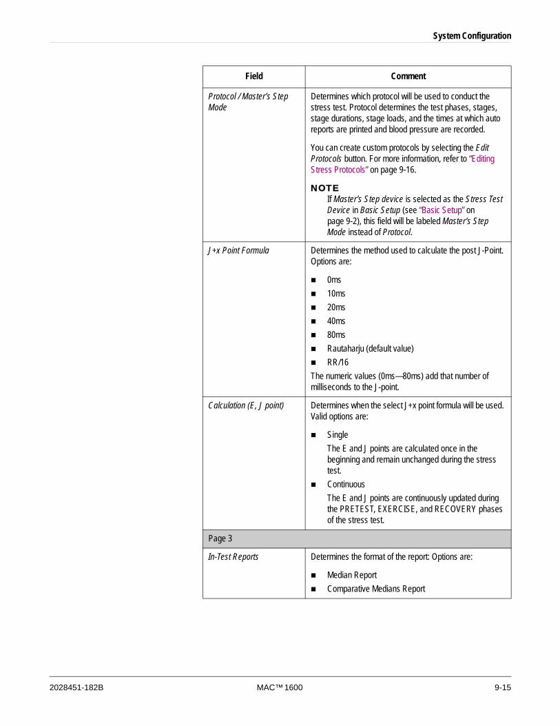
System Configuration
2028451-182B MAC™ 1600 9-15
Protocol / Master’s Step Mode
Determines which protocol will be used to conduct the stress test. Protocol determines the test phases, stages, stage durations, stage loads, and the times at which auto reports are printed and blood pressure are recorded.
You can create custom protocols by selecting the Edit Protocols button. For more information, refer to “Editing Stress Protocols” on page 9-16.
NOTEIf Master’s Step device is selected as the Stress Test Device in Basic Setup (see “Basic Setup” on page 9-2), this field will be labeled Master’s Step Mode instead of Protocol.
J+x Point Formula Determines the method used to calculate the post J-Point. Options are:
0ms10ms20ms40ms80msRautaharju (default value)RR/16
The numeric values (0ms—80ms) add that number of milliseconds to the J-point.
Calculation (E, J point) Determines when the select J+x point formula will be used. Valid options are:
SingleThe E and J points are calculated once in the beginning and remain unchanged during the stress test.ContinuousThe E and J points are continuously updated during the PRETEST, EXERCISE, and RECOVERY phases of the stress test.
Page 3
In-Test Reports Determines the format of the report: Options are:
Median ReportComparative Medians Report
Field Comment
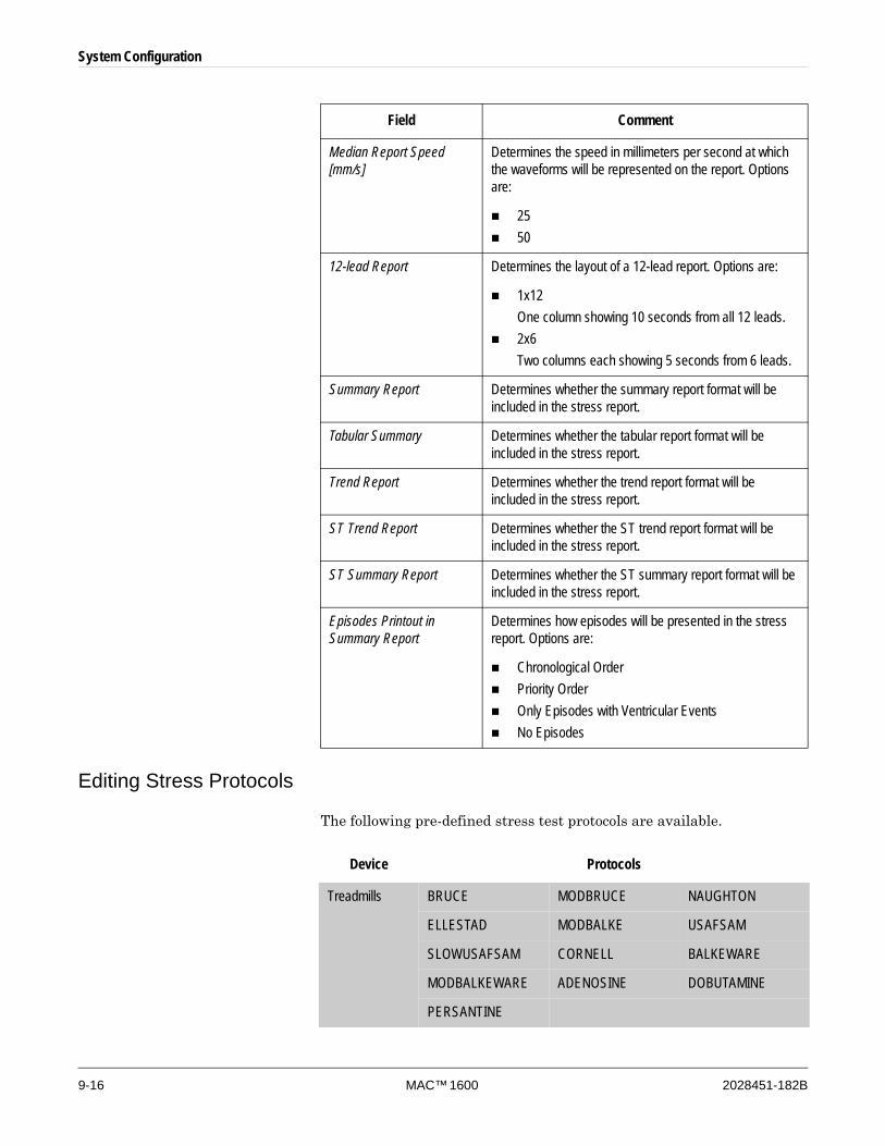
9-16 MAC™ 1600 2028451-182B
System Configuration
Editing Stress Protocols
The following pre-defined stress test protocols are available.
Median Report Speed [mm/s]
Determines the speed in millimeters per second at which the waveforms will be represented on the report. Options are:
2550
12-lead Report Determines the layout of a 12-lead report. Options are:
1x12One column showing 10 seconds from all 12 leads. 2x6Two columns each showing 5 seconds from 6 leads.
Summary Report Determines whether the summary report format will be included in the stress report.
Tabular Summary Determines whether the tabular report format will be included in the stress report.
Trend Report Determines whether the trend report format will be included in the stress report.
ST Trend Report Determines whether the ST trend report format will be included in the stress report.
ST Summary Report Determines whether the ST summary report format will be included in the stress report.
Episodes Printout in Summary Report
Determines how episodes will be presented in the stress report. Options are:
Chronological OrderPriority OrderOnly Episodes with Ventricular EventsNo Episodes
Field Comment
Device Protocols
Treadmills BRUCE MODBRUCE NAUGHTON
ELLESTAD MODBALKE USAFSAM
SLOWUSAFSAM CORNELL BALKEWARE
MODBALKEWARE ADENOSINE DOBUTAMINE
PERSANTINE
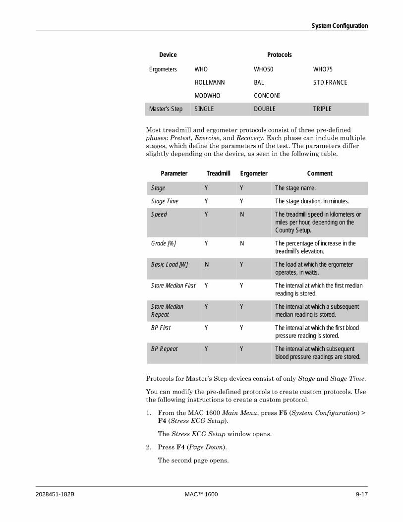
System Configuration
2028451-182B MAC™ 1600 9-17
Most treadmill and ergometer protocols consist of three pre-defined phases: Pretest, Exercise, and Recovery. Each phase can include multiple stages, which define the parameters of the test. The parameters differ slightly depending on the device, as seen in the following table.
Protocols for Master’s Step devices consist of only Stage and Stage Time.
You can modify the pre-defined protocols to create custom protocols. Use the following instructions to create a custom protocol.
1. From the MAC 1600 Main Menu, press F5 (System Configuration) > F4 (Stress ECG Setup).
The Stress ECG Setup window opens.
2. Press F4 (Page Down).
The second page opens.
Ergometers WHO WHO50 WHO75
HOLLMANN BAL STD.FRANCE
MODWHO CONCONI
Master’s Step SINGLE DOUBLE TRIPLE
Parameter Treadmill Ergometer Comment
Stage Y Y The stage name.
Stage Time Y Y The stage duration, in minutes.
Speed Y N The treadmill speed in kilometers or miles per hour, depending on the Country Setup.
Grade [%] Y N The percentage of increase in the treadmill’s elevation.
Basic Load [W] N Y The load at which the ergometer operates, in watts.
Store Median First Y Y The interval at which the first median reading is stored.
Store Median Repeat
Y Y The interval at which a subsequent median reading is stored.
BP First Y Y The interval at which the first blood pressure reading is stored.
BP Repeat Y Y The interval at which subsequent blood pressure readings are stored.
Device Protocols

9-18 MAC™ 1600 2028451-182B
System Configuration
3. Select the Edit Protocols button and press either Enter or the trimpad button.
For treadmills and ergometers, the Select Protocol window opens to display applicable protocols. Perform step 4 through step 16.
For Master’s Step devices, the Edit Master Step Post-Exercise window opens to display the display the post-exercise stages. Perform step 8 through step 12.
4. Press F2 (Add).
A list of templates opens.
5. Select the template to base the new protocol on.
The templates are based on the existing protocols. An additional Empty Protocol is also available.
6. Press F6 (OK).
The Add Protocol window opens.
7. Type a name for the new protocol and press F6 (OK).
The Protocol window opens with all the stages from the template. You can now add, edit, or delete stages.
8. To add a stage, do the following:
a. Select the stage that will precede the new stage.
b. Press F2 (Add Stage).
The selected stage is duplicated. Edit the duplicate stage as appropriate. Refer to step 9.
9. To edit a stage, do the following:
a. Select the stage to edit.
b. Press F1 (Edit).
The Edit Stage window opens.
c. Modify the stage parameters as appropriate.
Refer to the table preceding these instructions for a description of each parameter.
d. When you are done, press F6 (OK).
The Edit Stage window closes.
10. To delete a stage, do the following:
a. Select the stage to be deleted.
b. Press F3 (Delete Stage).
The selected stage is deleted.
11. To remove custom Master’s Step stages, press F4 (Factory Defaults).
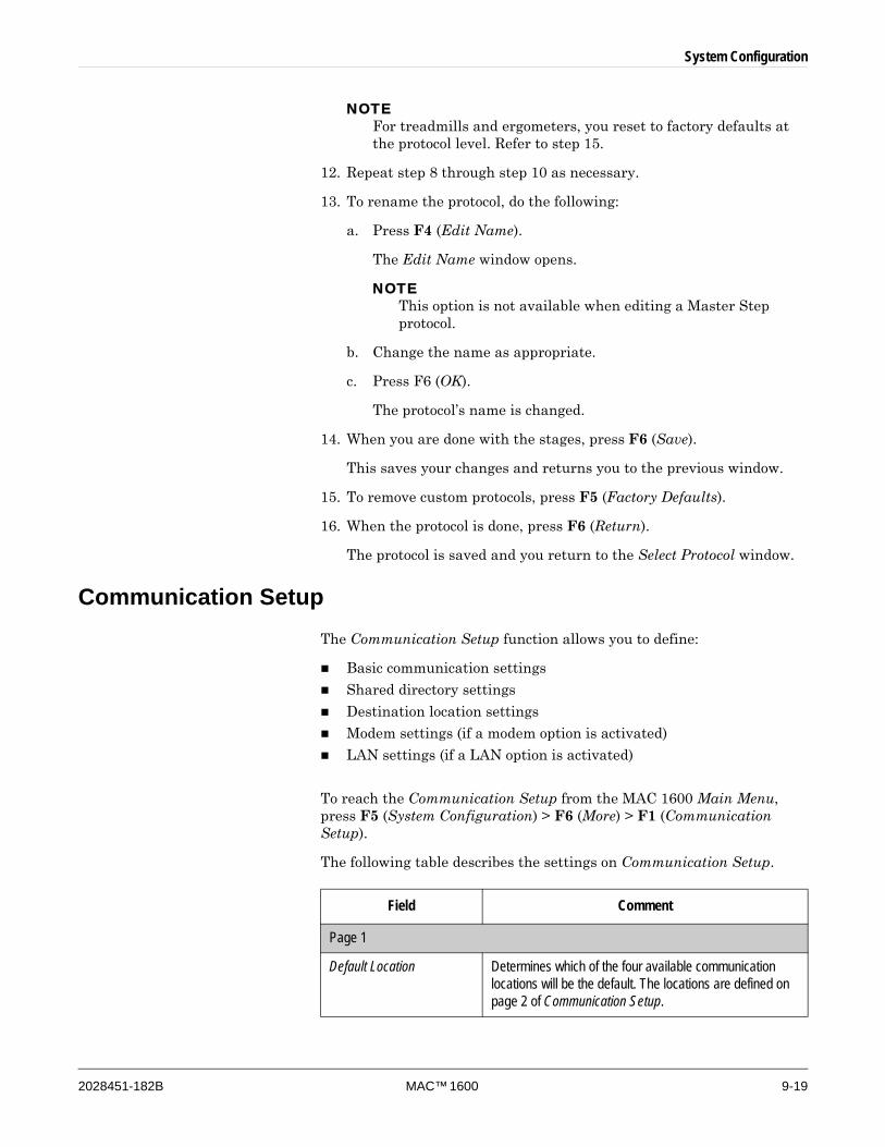
System Configuration
2028451-182B MAC™ 1600 9-19
NOTEFor treadmills and ergometers, you reset to factory defaults at the protocol level. Refer to step 15.
12. Repeat step 8 through step 10 as necessary.
13. To rename the protocol, do the following:
a. Press F4 (Edit Name).
The Edit Name window opens.
NOTEThis option is not available when editing a Master Step protocol.
b. Change the name as appropriate.
c. Press F6 (OK).
The protocol’s name is changed.
14. When you are done with the stages, press F6 (Save).
This saves your changes and returns you to the previous window.
15. To remove custom protocols, press F5 (Factory Defaults).
16. When the protocol is done, press F6 (Return).
The protocol is saved and you return to the Select Protocol window.
Communication SetupThe Communication Setup function allows you to define:
Basic communication settings
Shared directory settings
Destination location settings
Modem settings (if a modem option is activated)
LAN settings (if a LAN option is activated)
To reach the Communication Setup from the MAC 1600 Main Menu, press F5 (System Configuration) > F6 (More) > F1 (Communication Setup).
The following table describes the settings on Communication Setup.
Field Comment
Page 1
Default Location Determines which of the four available communication locations will be the default. The locations are defined on page 2 of Communication Setup.
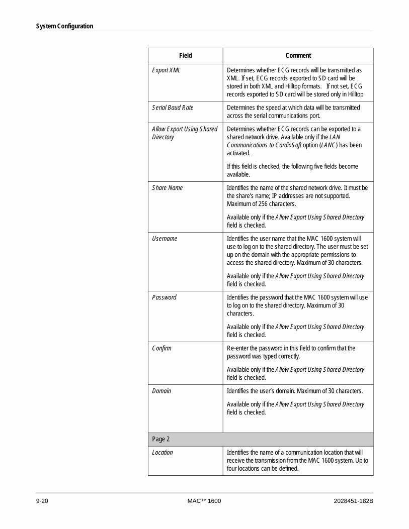
9-20 MAC™ 1600 2028451-182B
System Configuration
Export XML Determines whether ECG records will be transmitted as XML. If set, ECG records exported to SD card will be stored in both XML and Hilltop formats. If not set, ECG records exported to SD card will be stored only in Hilltop
Serial Baud Rate Determines the speed at which data will be transmitted across the serial communications port.
Allow Export Using Shared Directory
Determines whether ECG records can be exported to a shared network drive. Available only if the LAN Communications to CardioSoft option (LANC) has been activated.
If this field is checked, the following five fields become available.
Share Name Identifies the name of the shared network drive. It must be the share’s name; IP addresses are not supported. Maximum of 256 characters.
Available only if the Allow Export Using Shared Directory field is checked.
Username Identifies the user name that the MAC 1600 system will use to log on to the shared directory. The user must be set up on the domain with the appropriate permissions to access the shared directory. Maximum of 30 characters.
Available only if the Allow Export Using Shared Directory field is checked.
Password Identifies the password that the MAC 1600 system will use to log on to the shared directory. Maximum of 30 characters.
Available only if the Allow Export Using Shared Directory field is checked.
Confirm Re-enter the password in this field to confirm that the password was typed correctly.
Available only if the Allow Export Using Shared Directory field is checked.
Domain Identifies the user’s domain. Maximum of 30 characters.
Available only if the Allow Export Using Shared Directory field is checked.
Page 2
Location Identifies the name of a communication location that will receive the transmission from the MAC 1600 system. Up to four locations can be defined.
Field Comment
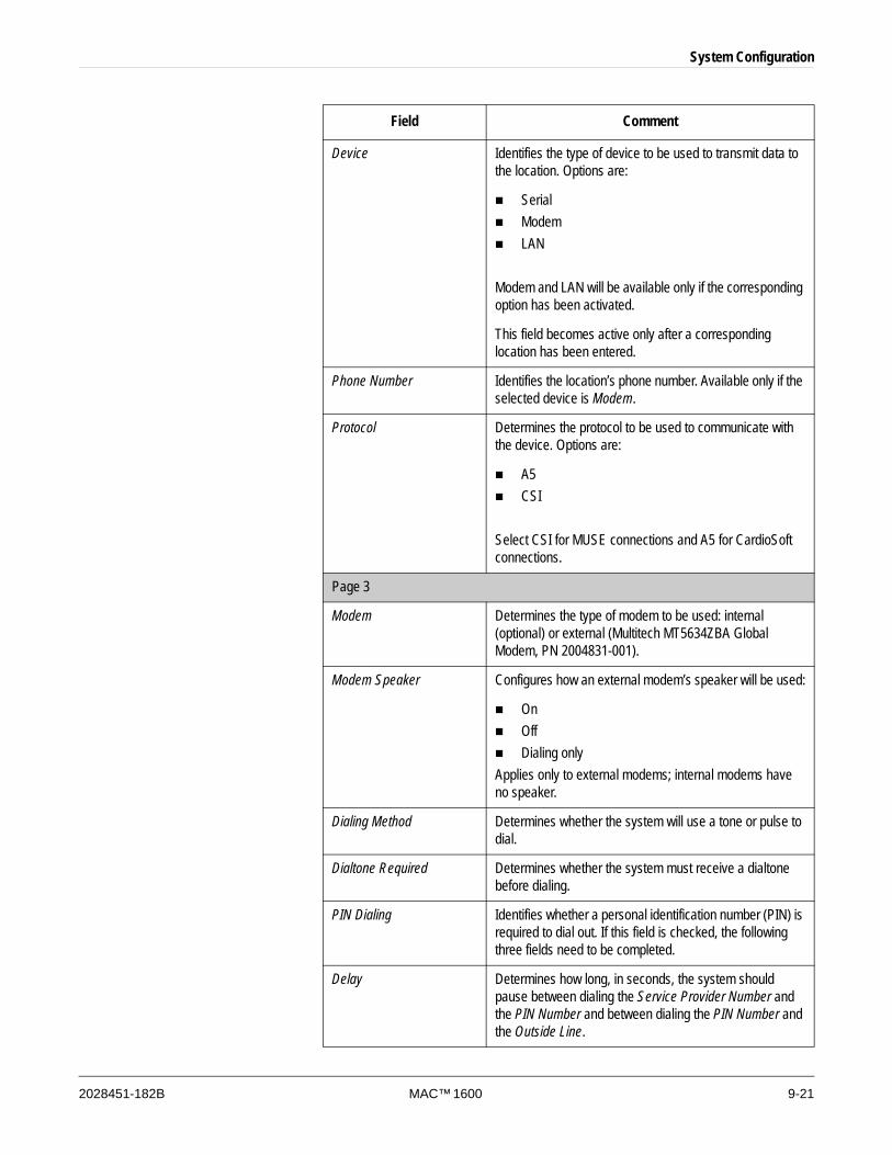
System Configuration
2028451-182B MAC™ 1600 9-21
Device Identifies the type of device to be used to transmit data to the location. Options are:
SerialModemLAN
Modem and LAN will be available only if the corresponding option has been activated.
This field becomes active only after a corresponding location has been entered.
Phone Number Identifies the location’s phone number. Available only if the selected device is Modem.
Protocol Determines the protocol to be used to communicate with the device. Options are:
A5CSI
Select CSI for MUSE connections and A5 for CardioSoft connections.
Page 3
Modem Determines the type of modem to be used: internal (optional) or external (Multitech MT5634ZBA Global Modem, PN 2004831-001).
Modem Speaker Configures how an external modem’s speaker will be used:
OnOffDialing only
Applies only to external modems; internal modems have no speaker.
Dialing Method Determines whether the system will use a tone or pulse to dial.
Dialtone Required Determines whether the system must receive a dialtone before dialing.
PIN Dialing Identifies whether a personal identification number (PIN) is required to dial out. If this field is checked, the following three fields need to be completed.
Delay Determines how long, in seconds, the system should pause between dialing the Service Provider Number and the PIN Number and between dialing the PIN Number and the Outside Line.
Field Comment
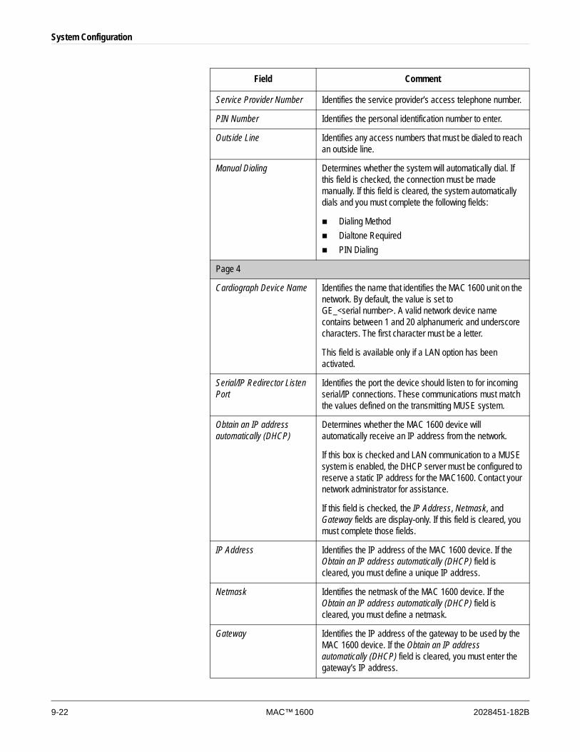
9-22 MAC™ 1600 2028451-182B
System Configuration
Service Provider Number Identifies the service provider’s access telephone number.
PIN Number Identifies the personal identification number to enter.
Outside Line Identifies any access numbers that must be dialed to reach an outside line.
Manual Dialing Determines whether the system will automatically dial. If this field is checked, the connection must be made manually. If this field is cleared, the system automatically dials and you must complete the following fields:
Dialing MethodDialtone RequiredPIN Dialing
Page 4
Cardiograph Device Name Identifies the name that identifies the MAC 1600 unit on the network. By default, the value is set to GE_<serial number>. A valid network device name contains between 1 and 20 alphanumeric and underscore characters. The first character must be a letter.
This field is available only if a LAN option has been activated.
Serial/IP Redirector Listen Port
Identifies the port the device should listen to for incoming serial/IP connections. These communications must match the values defined on the transmitting MUSE system.
Obtain an IP address automatically (DHCP)
Determines whether the MAC 1600 device will automatically receive an IP address from the network.
If this box is checked and LAN communication to a MUSE system is enabled, the DHCP server must be configured to reserve a static IP address for the MAC1600. Contact your network administrator for assistance.
If this field is checked, the IP Address, Netmask, and Gateway fields are display-only. If this field is cleared, you must complete those fields.
IP Address Identifies the IP address of the MAC 1600 device. If the Obtain an IP address automatically (DHCP) field is cleared, you must define a unique IP address.
Netmask Identifies the netmask of the MAC 1600 device. If the Obtain an IP address automatically (DHCP) field is cleared, you must define a netmask.
Gateway Identifies the IP address of the gateway to be used by the MAC 1600 device. If the Obtain an IP address automatically (DHCP) field is cleared, you must enter the gateway’s IP address.
Field Comment
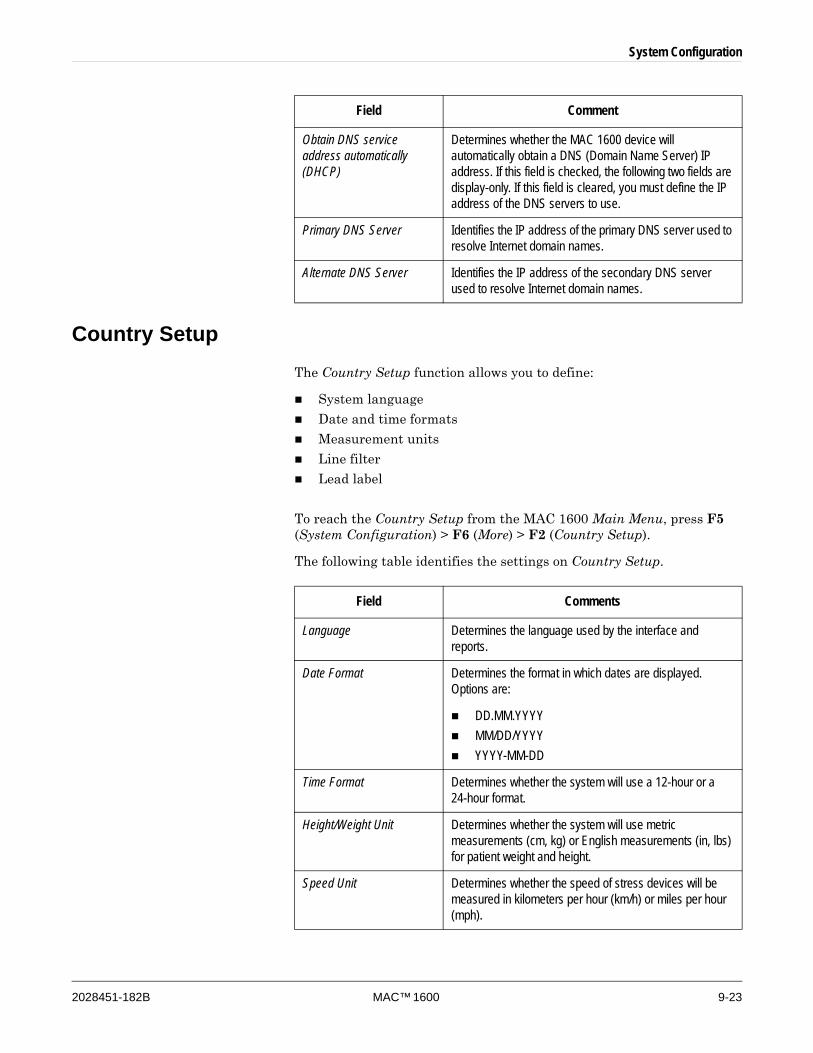
System Configuration
2028451-182B MAC™ 1600 9-23
Country SetupThe Country Setup function allows you to define:
System language
Date and time formats
Measurement units
Line filter
Lead label
To reach the Country Setup from the MAC 1600 Main Menu, press F5 (System Configuration) > F6 (More) > F2 (Country Setup).
The following table identifies the settings on Country Setup.
Obtain DNS service address automatically (DHCP)
Determines whether the MAC 1600 device will automatically obtain a DNS (Domain Name Server) IP address. If this field is checked, the following two fields are display-only. If this field is cleared, you must define the IP address of the DNS servers to use.
Primary DNS Server Identifies the IP address of the primary DNS server used to resolve Internet domain names.
Alternate DNS Server Identifies the IP address of the secondary DNS server used to resolve Internet domain names.
Field Comment
Field Comments
Language Determines the language used by the interface and reports.
Date Format Determines the format in which dates are displayed. Options are:
DD.MM.YYYYMM/DD/YYYYYYYY-MM-DD
Time Format Determines whether the system will use a 12-hour or a 24-hour format.
Height/Weight Unit Determines whether the system will use metric measurements (cm, kg) or English measurements (in, lbs) for patient weight and height.
Speed Unit Determines whether the speed of stress devices will be measured in kilometers per hour (km/h) or miles per hour (mph).
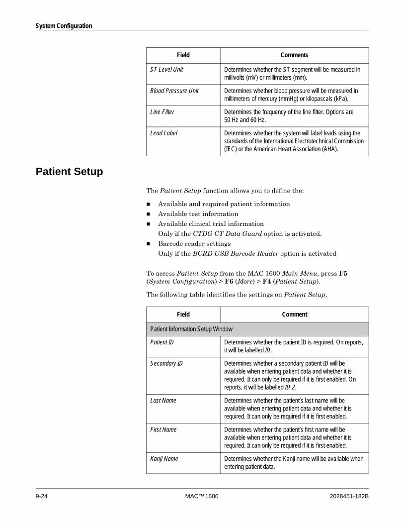
9-24 MAC™ 1600 2028451-182B
System Configuration
Patient SetupThe Patient Setup function allows you to define the:
Available and required patient information
Available test information
Available clinical trial information
Only if the CTDG CT Data Guard option is activated.
Barcode reader settings
Only if the BCRD USB Barcode Reader option is activated
To access Patient Setup from the MAC 1600 Main Menu, press F5 (System Configuration) > F6 (More) > F4 (Patient Setup).
The following table identifies the settings on Patient Setup.
ST Level Unit Determines whether the ST segment will be measured in millivolts (mV) or millimeters (mm).
Blood Pressure Unit Determines whether blood pressure will be measured in millimeters of mercury (mmHg) or kilopascals (kPa).
Line Filter Determines the frequency of the line filter. Options are 50 Hz and 60 Hz.
Lead Label Determines whether the system will label leads using the standards of the International Electrotechnical Commission (IEC) or the American Heart Association (AHA).
Field Comments
Field Comment
Patient Information Setup Window
Patient ID Determines whether the patient ID is required. On reports, it will be labelled ID.
Secondary ID Determines whether a secondary patient ID will be available when entering patient data and whether it is required. It can only be required if it is first enabled. On reports, it will be labelled ID 2.
Last Name Determines whether the patient’s last name will be available when entering patient data and whether it is required. It can only be required if it is first enabled.
First Name Determines whether the patient’s first name will be available when entering patient data and whether it is required. It can only be required if it is first enabled.
Kanji Name Determines whether the Kanji name will be available when entering patient data.
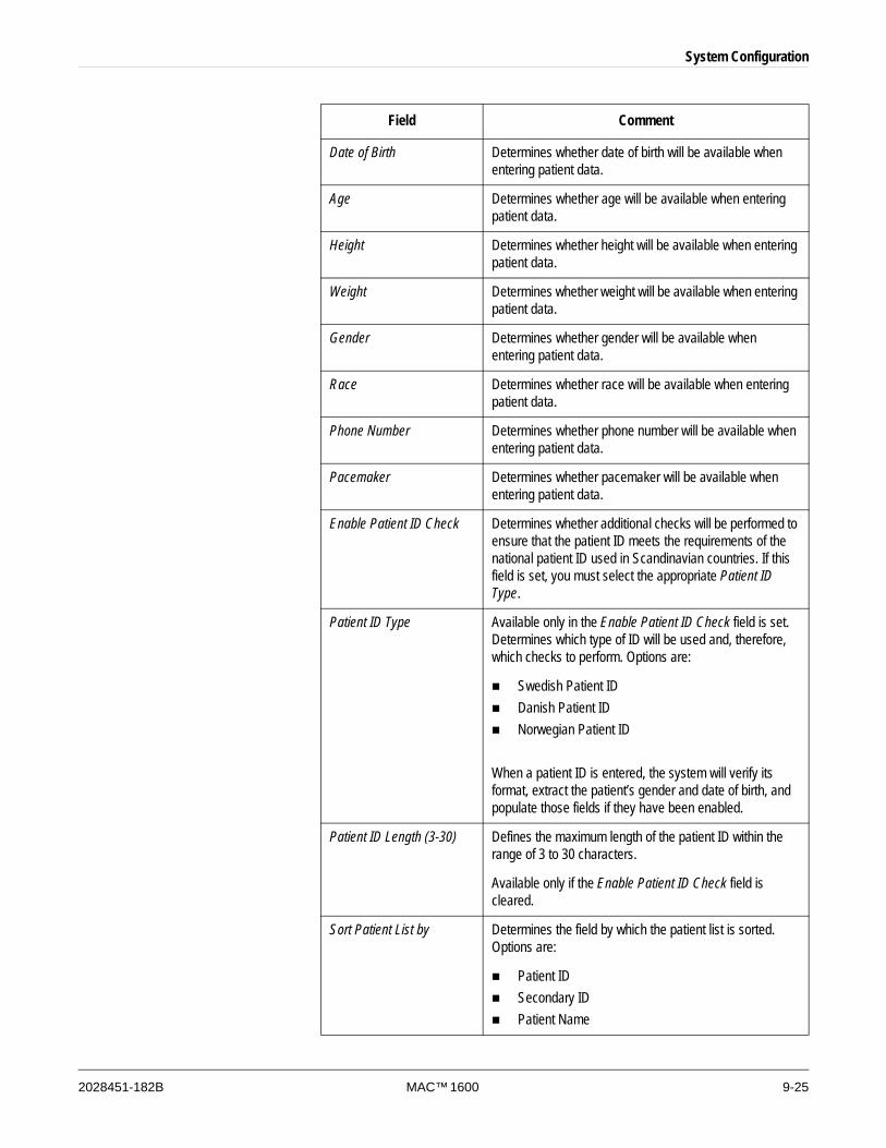
System Configuration
2028451-182B MAC™ 1600 9-25
Date of Birth Determines whether date of birth will be available when entering patient data.
Age Determines whether age will be available when entering patient data.
Height Determines whether height will be available when entering patient data.
Weight Determines whether weight will be available when entering patient data.
Gender Determines whether gender will be available when entering patient data.
Race Determines whether race will be available when entering patient data.
Phone Number Determines whether phone number will be available when entering patient data.
Pacemaker Determines whether pacemaker will be available when entering patient data.
Enable Patient ID Check Determines whether additional checks will be performed to ensure that the patient ID meets the requirements of the national patient ID used in Scandinavian countries. If this field is set, you must select the appropriate Patient ID Type.
Patient ID Type Available only in the Enable Patient ID Check field is set. Determines which type of ID will be used and, therefore, which checks to perform. Options are:
Swedish Patient IDDanish Patient IDNorwegian Patient ID
When a patient ID is entered, the system will verify its format, extract the patient’s gender and date of birth, and populate those fields if they have been enabled.
Patient ID Length (3-30) Defines the maximum length of the patient ID within the range of 3 to 30 characters.
Available only if the Enable Patient ID Check field is cleared.
Sort Patient List by Determines the field by which the patient list is sorted. Options are:
Patient IDSecondary IDPatient Name
Field Comment
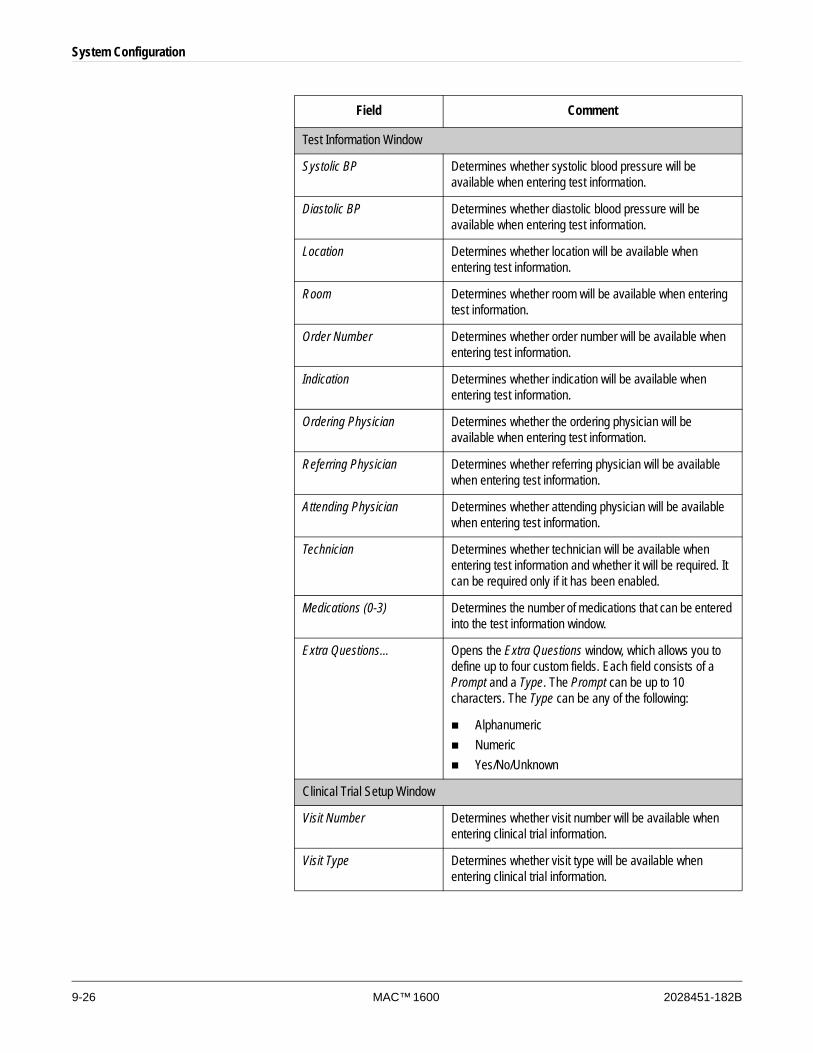
9-26 MAC™ 1600 2028451-182B
System Configuration
Test Information Window
Systolic BP Determines whether systolic blood pressure will be available when entering test information.
Diastolic BP Determines whether diastolic blood pressure will be available when entering test information.
Location Determines whether location will be available when entering test information.
Room Determines whether room will be available when entering test information.
Order Number Determines whether order number will be available when entering test information.
Indication Determines whether indication will be available when entering test information.
Ordering Physician Determines whether the ordering physician will be available when entering test information.
Referring Physician Determines whether referring physician will be available when entering test information.
Attending Physician Determines whether attending physician will be available when entering test information.
Technician Determines whether technician will be available when entering test information and whether it will be required. It can be required only if it has been enabled.
Medications (0-3) Determines the number of medications that can be entered into the test information window.
Extra Questions… Opens the Extra Questions window, which allows you to define up to four custom fields. Each field consists of a Prompt and a Type. The Prompt can be up to 10 characters. The Type can be any of the following:
AlphanumericNumericYes/No/Unknown
Clinical Trial Setup Window
Visit Number Determines whether visit number will be available when entering clinical trial information.
Visit Type Determines whether visit type will be available when entering clinical trial information.
Field Comment
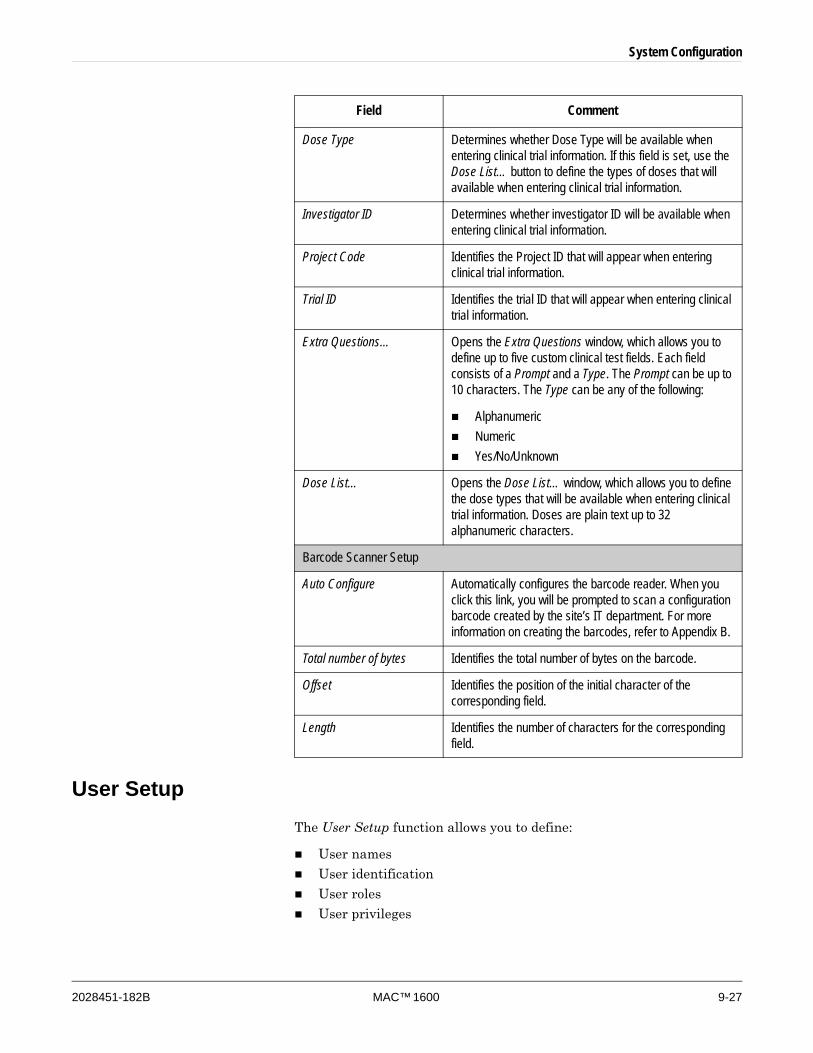
System Configuration
2028451-182B MAC™ 1600 9-27
User SetupThe User Setup function allows you to define:
User names
User identification
User roles
User privileges
Dose Type Determines whether Dose Type will be available when entering clinical trial information. If this field is set, use the Dose List… button to define the types of doses that will available when entering clinical trial information.
Investigator ID Determines whether investigator ID will be available when entering clinical trial information.
Project Code Identifies the Project ID that will appear when entering clinical trial information.
Trial ID Identifies the trial ID that will appear when entering clinical trial information.
Extra Questions… Opens the Extra Questions window, which allows you to define up to five custom clinical test fields. Each field consists of a Prompt and a Type. The Prompt can be up to 10 characters. The Type can be any of the following:
AlphanumericNumericYes/No/Unknown
Dose List… Opens the Dose List… window, which allows you to define the dose types that will be available when entering clinical trial information. Doses are plain text up to 32 alphanumeric characters.
Barcode Scanner Setup
Auto Configure Automatically configures the barcode reader. When you click this link, you will be prompted to scan a configuration barcode created by the site’s IT department. For more information on creating the barcodes, refer to Appendix B.
Total number of bytes Identifies the total number of bytes on the barcode.
Offset Identifies the position of the initial character of the corresponding field.
Length Identifies the number of characters for the corresponding field.
Field Comment
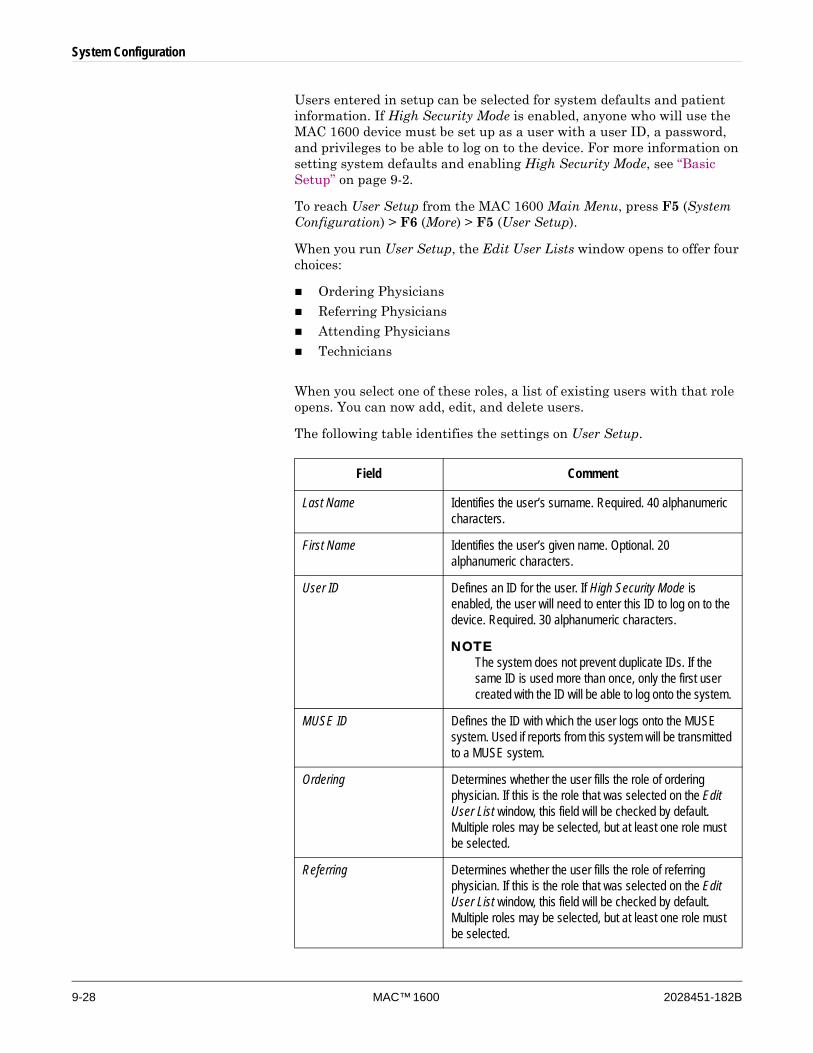
9-28 MAC™ 1600 2028451-182B
System Configuration
Users entered in setup can be selected for system defaults and patient information. If High Security Mode is enabled, anyone who will use the MAC 1600 device must be set up as a user with a user ID, a password, and privileges to be able to log on to the device. For more information on setting system defaults and enabling High Security Mode, see “Basic Setup” on page 9-2.
To reach User Setup from the MAC 1600 Main Menu, press F5 (System Configuration) > F6 (More) > F5 (User Setup).
When you run User Setup, the Edit User Lists window opens to offer four choices:
Ordering Physicians
Referring Physicians
Attending Physicians
Technicians
When you select one of these roles, a list of existing users with that role opens. You can now add, edit, and delete users.
The following table identifies the settings on User Setup.
Field Comment
Last Name Identifies the user’s surname. Required. 40 alphanumeric characters.
First Name Identifies the user’s given name. Optional. 20 alphanumeric characters.
User ID Defines an ID for the user. If High Security Mode is enabled, the user will need to enter this ID to log on to the device. Required. 30 alphanumeric characters.
NOTEThe system does not prevent duplicate IDs. If the same ID is used more than once, only the first user created with the ID will be able to log onto the system.
MUSE ID Defines the ID with which the user logs onto the MUSE system. Used if reports from this system will be transmitted to a MUSE system.
Ordering Determines whether the user fills the role of ordering physician. If this is the role that was selected on the Edit User List window, this field will be checked by default. Multiple roles may be selected, but at least one role must be selected.
Referring Determines whether the user fills the role of referring physician. If this is the role that was selected on the Edit User List window, this field will be checked by default. Multiple roles may be selected, but at least one role must be selected.
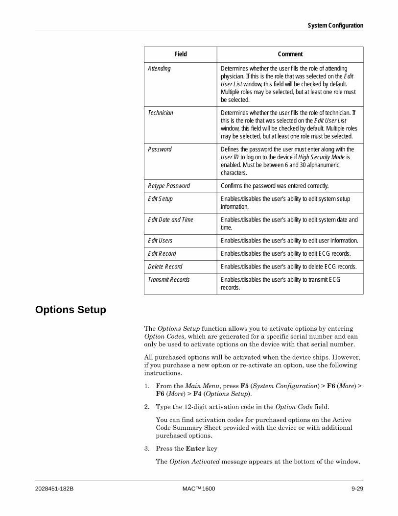
System Configuration
2028451-182B MAC™ 1600 9-29
Options SetupThe Options Setup function allows you to activate options by entering Option Codes, which are generated for a specific serial number and can only be used to activate options on the device with that serial number.
All purchased options will be activated when the device ships. However, if you purchase a new option or re-activate an option, use the following instructions.
1. From the Main Menu, press F5 (System Configuration) > F6 (More) > F6 (More) > F4 (Options Setup).
2. Type the 12-digit activation code in the Option Code field.
You can find activation codes for purchased options on the Active Code Summary Sheet provided with the device or with additional purchased options.
3. Press the Enter key
The Option Activated message appears at the bottom of the window.
Attending Determines whether the user fills the role of attending physician. If this is the role that was selected on the Edit User List window, this field will be checked by default. Multiple roles may be selected, but at least one role must be selected.
Technician Determines whether the user fills the role of technician. If this is the role that was selected on the Edit User List window, this field will be checked by default. Multiple roles may be selected, but at least one role must be selected.
Password Defines the password the user must enter along with the User ID to log on to the device if High Security Mode is enabled. Must be between 6 and 30 alphanumeric characters.
Retype Password Confirms the password was entered correctly.
Edit Setup Enables/disables the user’s ability to edit system setup information.
Edit Date and Time Enables/disables the user’s ability to edit system date and time.
Edit Users Enables/disables the user’s ability to edit user information.
Edit Record Enables/disables the user’s ability to edit ECG records.
Delete Record Enables/disables the user’s ability to delete ECG records.
Transmit Records Enables/disables the user’s ability to transmit ECG records.
Field Comment
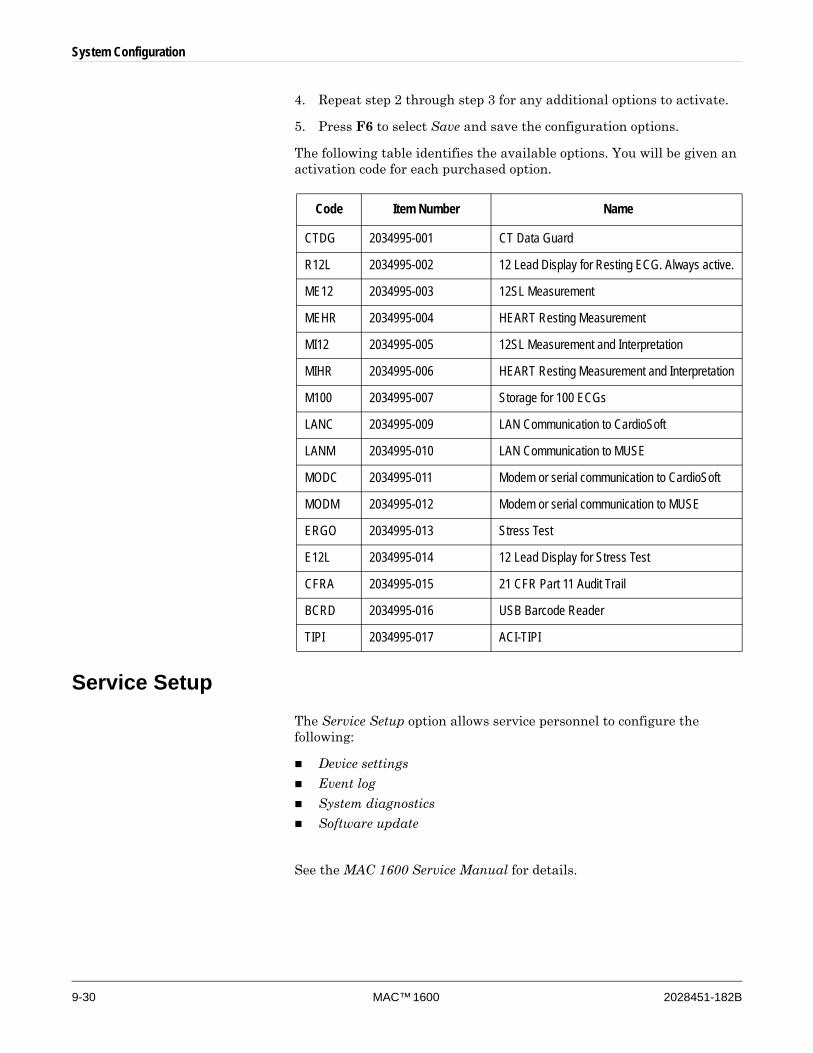
9-30 MAC™ 1600 2028451-182B
System Configuration
4. Repeat step 2 through step 3 for any additional options to activate.
5. Press F6 to select Save and save the configuration options.
The following table identifies the available options. You will be given an activation code for each purchased option.
Service SetupThe Service Setup option allows service personnel to configure the following:
Device settings
Event log
System diagnostics
Software update
See the MAC 1600 Service Manual for details.
Code Item Number Name
CTDG 2034995-001 CT Data Guard
R12L 2034995-002 12 Lead Display for Resting ECG. Always active.
ME12 2034995-003 12SL Measurement
MEHR 2034995-004 HEART Resting Measurement
MI12 2034995-005 12SL Measurement and Interpretation
MIHR 2034995-006 HEART Resting Measurement and Interpretation
M100 2034995-007 Storage for 100 ECGs
LANC 2034995-009 LAN Communication to CardioSoft
LANM 2034995-010 LAN Communication to MUSE
MODC 2034995-011 Modem or serial communication to CardioSoft
MODM 2034995-012 Modem or serial communication to MUSE
ERGO 2034995-013 Stress Test
E12L 2034995-014 12 Lead Display for Stress Test
CFRA 2034995-015 21 CFR Part 11 Audit Trail
BCRD 2034995-016 USB Barcode Reader
TIPI 2034995-017 ACI-TIPI
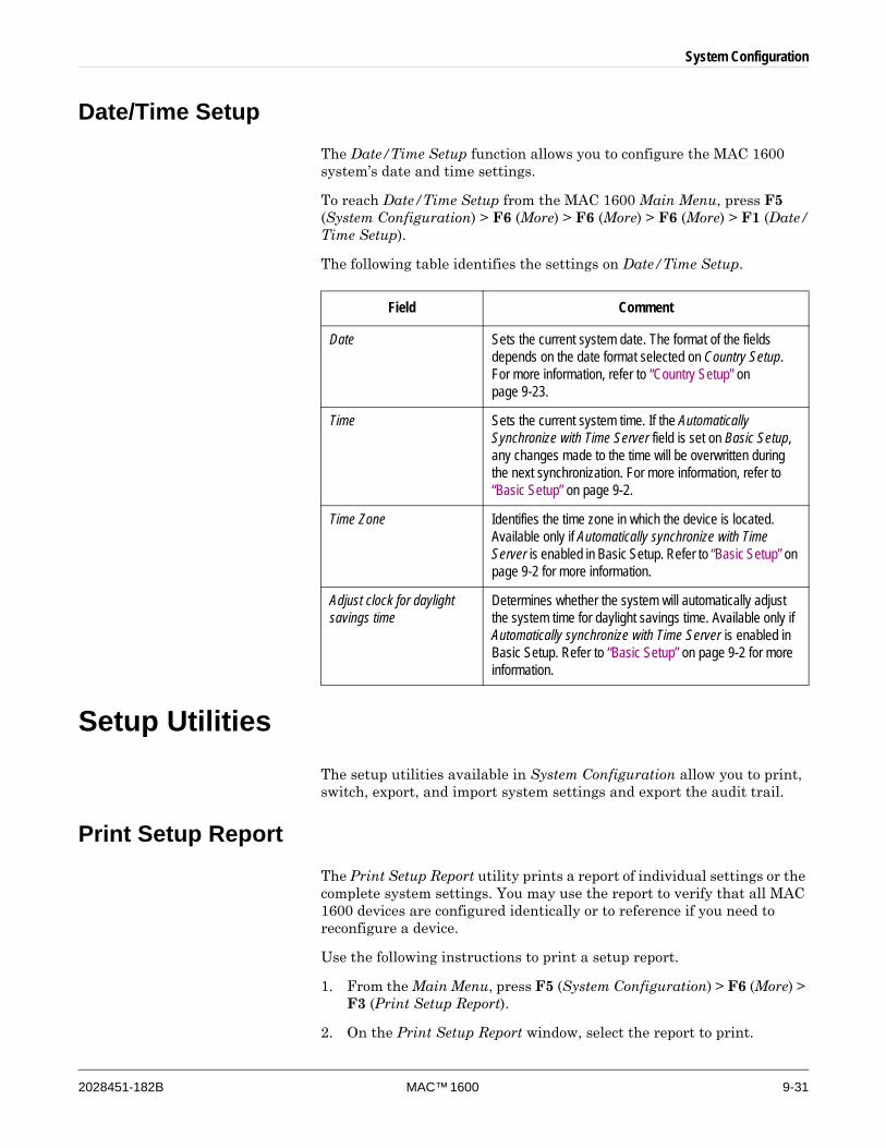
System Configuration
2028451-182B MAC™ 1600 9-31
Date/Time SetupThe Date/Time Setup function allows you to configure the MAC 1600 system’s date and time settings.
To reach Date/Time Setup from the MAC 1600 Main Menu, press F5 (System Configuration) > F6 (More) > F6 (More) > F6 (More) > F1 (Date/Time Setup).
The following table identifies the settings on Date/Time Setup.
Setup UtilitiesThe setup utilities available in System Configuration allow you to print, switch, export, and import system settings and export the audit trail.
Print Setup ReportThe Print Setup Report utility prints a report of individual settings or the complete system settings. You may use the report to verify that all MAC 1600 devices are configured identically or to reference if you need to reconfigure a device.
Use the following instructions to print a setup report.
1. From the Main Menu, press F5 (System Configuration) > F6 (More) > F3 (Print Setup Report).
2. On the Print Setup Report window, select the report to print.
Field Comment
Date Sets the current system date. The format of the fields depends on the date format selected on Country Setup. For more information, refer to “Country Setup” on page 9-23.
Time Sets the current system time. If the Automatically Synchronize with Time Server field is set on Basic Setup, any changes made to the time will be overwritten during the next synchronization. For more information, refer to “Basic Setup” on page 9-2.
Time Zone Identifies the time zone in which the device is located. Available only if Automatically synchronize with Time Server is enabled in Basic Setup. Refer to “Basic Setup” on page 9-2 for more information.
Adjust clock for daylight savings time
Determines whether the system will automatically adjust the system time for daylight savings time. Available only if Automatically synchronize with Time Server is enabled in Basic Setup. Refer to “Basic Setup” on page 9-2 for more information.
9-32 MAC™ 1600 2028451-182B
System Configuration
Basic Setup
Resting Setup
Arrhythmia Setup
Stress Setup
Communication Setup
Country Setup
Patient Setup
User Setup
Options Setup
Complete Setup
3. When you are done, press F6 (Return) to return to the Main Menu.
Select SetupThe Select Setup utility allows you to save up to five system configurations and switch between them. This is useful if the device is shared by departments or used in multiple clinical trials.
Use the following instructions to save and load configuration files.
1. From the Main Menu, press F5 (System Configuration) > F6 (More) > F6 (More) > F1 (Select Setup).
The Select Setup window opens. The name of the setup currently being used by the system appears in the Loaded Setup field.
2. To save a copy of the current setup, do the following:
a. Press F3 (Save As).
The Setup Name window opens.
b. Type a name for the configuration and press F6 (Save).
The configuration is saved, and the Setup Name window closes.
3. To load a different setup, do the following:
a. Select the setup to load.
b. Press F1 (Load Setup).
c. Reboot the unit.
The unit must be powered off and on for all setup changes to take effect, especially if the new setup includes a change to the language setting: language will not change until the unit reboots.
4. To delete a setup file, do the following:
a. Select the file to delete.
b. Press F2 (Delete).
You are prompted to confirm the deletion.
System Configuration
2028451-182B MAC™ 1600 9-33
c. Press F6 (OK).
NOTEYou cannot delete a configuration that is currently loaded.
5. To change the name of a system setup file, do the following:
a. Select the setup file to change.
b. Press F4 (Edit Name).
The Setup Name window opens.
c. Type the new name and press F6 (Save).
6. To remove all custom settings, do the following:
a. Select the setup file to reset.
b. Press F5 (Factory Defaults).
c. When prompted to confirm, press F6 (Save).
7. When you are done, press F6 (Return) to exit.
Export Setup The Export Setup utility allows you to export saved settings from the MAC 1600 system to an SD card. This SD card can then be used to import the settings to another MAC 1600 system, greatly simplifying the installation and configuration of multiple MAC 1600 systems.
1. Insert the SD card.
2. From the Main Menu, press F5 (System Configuration) > F6 (More) > F6 (More) > F3 (Export Setup).
The Select Setup for Export window opens. All saved settings on the device are listed in the left hand column. All saved settings on the SD card are listed in the right hand column.
3. In the left hand pane, select the setup file to be exported.
4. Press F1 (Export).
The selected file is copied to the SD card and appears in the right hand column.
5. Repeat step 3 through step 4 for each saved configuration file to be exported.
6. When you are done, press F6 (Return).

9-34 MAC™ 1600 2028451-182B
System Configuration
Import SetupThe Import Setup utility allows to import up to five system setup files from another MAC 1600 system that were exported to an SD card. This feature is useful to sites with multiple systems that need to have the same or similar setups.
1. Insert the SD card with the saved setup file.
2. From the Main Menu, press F5 (System Configuration) > F6 (More) > F6 (More) > F2 (Import).
The Select Setup for Import window opens. All saved settings on the device are listed in the left hand column. All saved settings on the SD card are listed in the right hand column.
3. In the right hand pane, select the setup file to be imported.
4. Press F1 (Import).
The selected file is copied to the device and appears in the left hand column.
5. Repeat step 3 through step 4 for each saved configuration file to be imported.
6. When you are done, press F6 (Return).
Exporting Audit TrailThe Audit Trail Export function copies the system audit trail in XML format to an SD card and then clears the audit trail on the MAC 1600 system. If a previous audit trail exists on the SD card, it will be overwritten automatically by the new audit trail.
GE recommends exporting the audit trail weekly to long term storage to meet archive requirements. If the audit trail is not exported regularly, it will consume storage space and reduce the number of ECGs that can be stored on the device
To export an audit trail, the following conditions must be met:
High Security Mode must be enabled.
See “Basic Setup” on page 9-2.
Audit Trail must be enabled.
See “Basic Setup” on page 9-2.
The user must have the Edit Setup and Delete Records permissions set.
See “User Setup” on page 9-27.
Use the following instructions to export the audit trail to an SD card:
1. Insert an SD card into the MAC 1600 unit.

System Configuration
2028451-182B MAC™ 1600 9-35
2. From the Main Menu, press F5 (System Configuration) > F6 (More) > F6 (More) > F6 (More) > F4 (Export Audit ).
When the audit trail has been copied to the SD card and cleared from the system, a message will notify you the export was successful.
After the XML file has been exported, you can review or print the audit trail as needed. For more information on how to parse the XML file for viewing or printing, refer to the GE Cardiology Open XML manual (PN 2025762-163).

9-36 MAC™ 1600 2028451-182B
System Configuration

2028451-182B MAC™ 1600 10-1
10 Maintenance

10-2 MAC™ 1600 2028451-182B
Maintenance
IntroductionRegular maintenance, irrespective of usage, is essential to ensure that the equipment functions when required. This chapter provides basic maintenance information for the following components:
MAC 1600 device
Cables and leadwires
Paper
Battery
Supplies and accessories
See the documentation provided with your peripherals for additional maintenance procedures.
WARNINGMAINTENANCE — Failure on the part of all responsible individuals, hospitals, or institutions employing this device to implement the recommended maintenance schedule may result in equipment failure and possible health hazards. The manufacturer does not in any manner assume the responsibility for performing the recommended maintenance schedule unless an Equipment Maintenance Agreement exists. The sole responsibility rests with the individuals, hospitals, or institutions employing the device.
MAC 1600 MaintenanceThe MAC 1600 ECG Analysis System is designed to require little more than regular inspection and cleaning to function properly. Any additional maintenance should be performed by qualified GE service personnel.
CAUTIONELECTRICAL HAZARD — Improper handling during inspection or cleaning could result in electrical shock. To avoid potential shock, observe the following guidelines at all times:
Before inspecting or cleaning the system, turn it off, unplug it from AC power, and remove the battery.
Do NOT immerse any part of the equipment in water.
Maintenance
2028451-182B MAC™ 1600 10-3
Inspecting the EquipmentPerform a visual inspection daily, preferably before the equipment’s first use each day. During the inspection, verify that the device meets the following minimum conditions:
The case and display screen are free of cracks and other damage.
All plugs, cords, cables, and connectors are free of kinks, frays, and other damage.
All cords and connectors are securely seated.
All keys and controls operate properly.
If you notice any items that need repair, contact an authorized service representative to make the repairs. Discontinue using the device until the appropriate repairs can be made.
Cleaning the DeviceClean the exterior surface of the MAC 1600 device monthly, or more frequently if needed.
Cleaning Materials to Use
Use the following materials to clean the device:
Mild dishwashing detergent
Clean, soft cloth (2)
Water
Cleaning Materials to Avoid
DO NOT use any of the following materials to clean the device, because their use may damage equipment surfaces.
Organic solvents
Ammonia-based solvents
Abrasive cleaning agents
Alcohol
Virex
Sani-Master
Cleaning the MAC 1600 Surfaces
Use the following procedure to clean the surfaces of the MAC 1600 device.
1. Dilute mild dishwashing detergent in water to create a cleaning solution.

10-4 MAC™ 1600 2028451-182B
Maintenance
2. Soak a clean cloth in the solution and wring out any excess.
3. Thoroughly wipe the surface of the MAC 1600 device with the damp cloth.
Do NOT drip the solution or any liquid on the writer assembly.
Avoid contact with open vents, plugs, or connectors.
4. Repeat step 2 and step 3 as necessary until the surface is adequately cleaned.
5. Wipe the surfaces with a dry, clean cloth or paper towel.
Cable and Leadwire MaintenanceProper care and maintenance of the cables and leadwires used by the MAC 1600 ECG Analysis System consists of:
Cleaning the cables and leadwires,
Storing the cables and leadwires, and
Replacing the cables and leadwires.
NOTEThe information in this section applies to the Multi-Link acquisition cable and leadwires. For systems with the optional KISS system, see the KISS operator’s manual for maintenance information.
Sanitizing Cables and LeadwiresCables and leadwires come into contact with patients and, therefore, should be cleaned and disinfected after every use. If necessary, they can also be sterilized.
Before cleaning and disinfecting the cables and leadwires, you need to know:
What cleaning materials can be used
What disinfectants can be used
What cleaning materials should be avoided
Cleaning Materials to Use
Use the following materials to clean the cables and leadwires:
Mild dishwashing detergent
Clean, soft cloth (2)
Water
Maintenance
2028451-182B MAC™ 1600 10-5
Disinfectant to Use
In accordance with the APIC Guidelines for Selection and Use of Disinfectants (1996), use sodium hypochlorite (5.2% household bleach) to disinfect the cables and leadwires.
Sodium hypochlorite can be in the form of a liquid or a wipe as long as it falls within the following range:
Minimum dilution of 1:500 (minimum of 100 ppm free chlorine)
Maximum dilution of 1:10
Cleaning Materials To Avoid
DO NOT use the following materials to clean the cables or leadwires:
Sani-Cloth® Wipes
Ascepti® Wipes
HB Quat®
Clorox® Wipes
Over-the-counter detergents (Fantastic®, Tilex®, etc.).
Conductive solutions
Solutions or products that contain any of the following:
Abrasive cleaners or solvents
Acetone
Alcohol-based cleaning agents
Ammonium Chloride
Betadine
Chlorides, wax, or wax compounds
Ketone
Sodium salts
Use of these materials or materials that contain similar active ingredients and solutions could result in:
Product discoloration,
Metal part corrosion,
Brittle wires and connectors,
Reduced product life,
Unit malfunction, and
Void warranty.
Cautions
Observe the following cautions when cleaning cables and leadwires:
Never immerse cables or leadwires in any liquid.
Never pour or spray any liquid directly onto cables or leadwires
Never permit fluid to seep into connections or openings.

10-6 MAC™ 1600 2028451-182B
Maintenance
Never autoclave or steam clean cables or leadwires.
Always wipe gently to avoid pulling long wires from the connectors.
Always remove cables and leadwires from the device before cleaning.
Failure to observe these cautions could result in damage to the contact metal ends, thereby affecting signal quality.
Cleaning Cables and Leadwires
Use the following procedure to clean the cables and leadwires.
NOTECleaning removes dirt and marks but does not disinfect.
1. Dilute mild dishwashing detergent in water to create a cleaning solution.
2. Soak a clean cloth in the solution and wring out any excess.
3. Thoroughly wipe the exterior of the cables and leadwires with the damp cloth.
4. Repeat step 2 and step 3 as necessary until adequately cleaned.
5. Wipe with a dry, clean cloth or paper towel and let air dry.
Disinfecting Cables and Leadwires
Use the following procedure to disinfect the cables and leadwires.
NOTEClean and dry the cables and leadwires before disinfecting them.
1. Use a lint-free cloth or wipe with a solution of Sodium Hypochloride.
2. Wring excess liquid from the cloth.
3. Gently wipe the cabling.
4. Wipe off the disinfectant with a clean, lightly moistened cloth.
NOTEIf fluid pools around the connectors, blot dry with a soft, lint-free cloth.
5. Wipe with a dry, lint-free cloth and let air dry for at least 30 minutes.
NOTEDrying times vary based on the environmental conditions.
DO NOT use excessive drying techniques, such as ovens, forced heat, or sun drying.
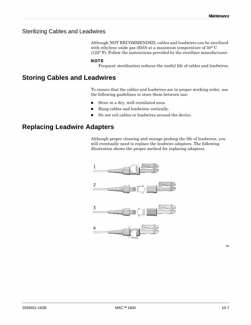
Maintenance
2028451-182B MAC™ 1600 10-7
Sterilizing Cables and Leadwires
Although NOT RECOMMENDED, cables and leadwires can be sterilized with ethylene oxide gas (EtO) at a maximum temperature of 50° C (122° F). Follow the instructions provided by the sterilizer manufacturer.
NOTEFrequent sterilization reduces the useful life of cables and leadwires.
Storing Cables and LeadwiresTo ensure that the cables and leadwires are in proper working order, use the following guidelines to store them between use:
Store in a dry, well-ventilated area.
Hang cables and leadwires vertically.
Do not coil cables or leadwires around the device.
Replacing Leadwire AdaptersAlthough proper cleaning and storage prolong the life of leadwires, you will eventually need to replace the leadwire adapters. The following illustration shows the proper method for replacing adapters.
23A
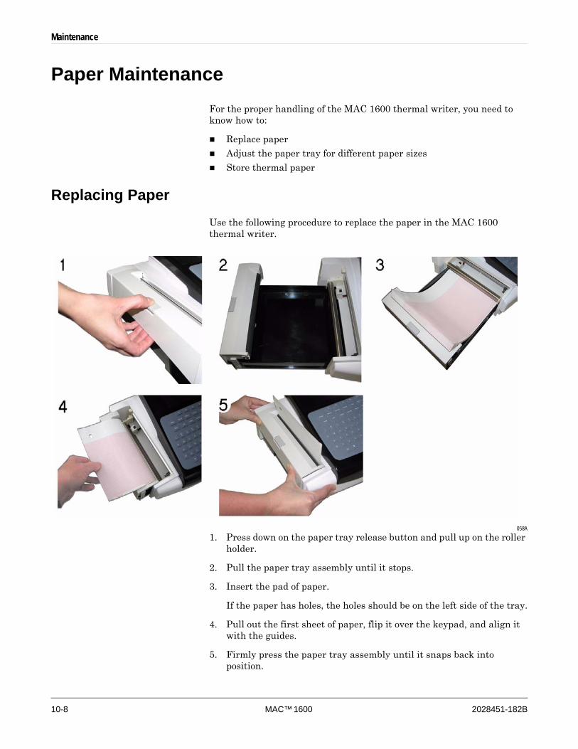
10-8 MAC™ 1600 2028451-182B
Maintenance
Paper MaintenanceFor the proper handling of the MAC 1600 thermal writer, you need to know how to:
Replace paper
Adjust the paper tray for different paper sizes
Store thermal paper
Replacing PaperUse the following procedure to replace the paper in the MAC 1600 thermal writer.
058A
1. Press down on the paper tray release button and pull up on the roller holder.
2. Pull the paper tray assembly until it stops.
3. Insert the pad of paper.
If the paper has holes, the holes should be on the left side of the tray.
4. Pull out the first sheet of paper, flip it over the keypad, and align it with the guides.
5. Firmly press the paper tray assembly until it snaps back into position.

Maintenance
2028451-182B MAC™ 1600 10-9
Adjusting the Paper Tray for Paper SizeThe MAC 1600 thermal writer supports two paper sizes: U.S. Letter (8.5” x 11”) and A4. When the device ships, the paper tray is configured to use the appropriate paper size for the destination location. Use the following instructions to change the paper size by moving the spacers in the paper tray.
1. Press down on the paper tray release button and pull up on the roller holder.
013A
2. Pull the paper tray until it stops.
3. Press and hold the release button on the bottom of the device and pull the paper tray to remove it completely from the device.
014A
4. Adjust the placement of the paper spacers for the paper size you will be using.
Refer to the following illustrations.
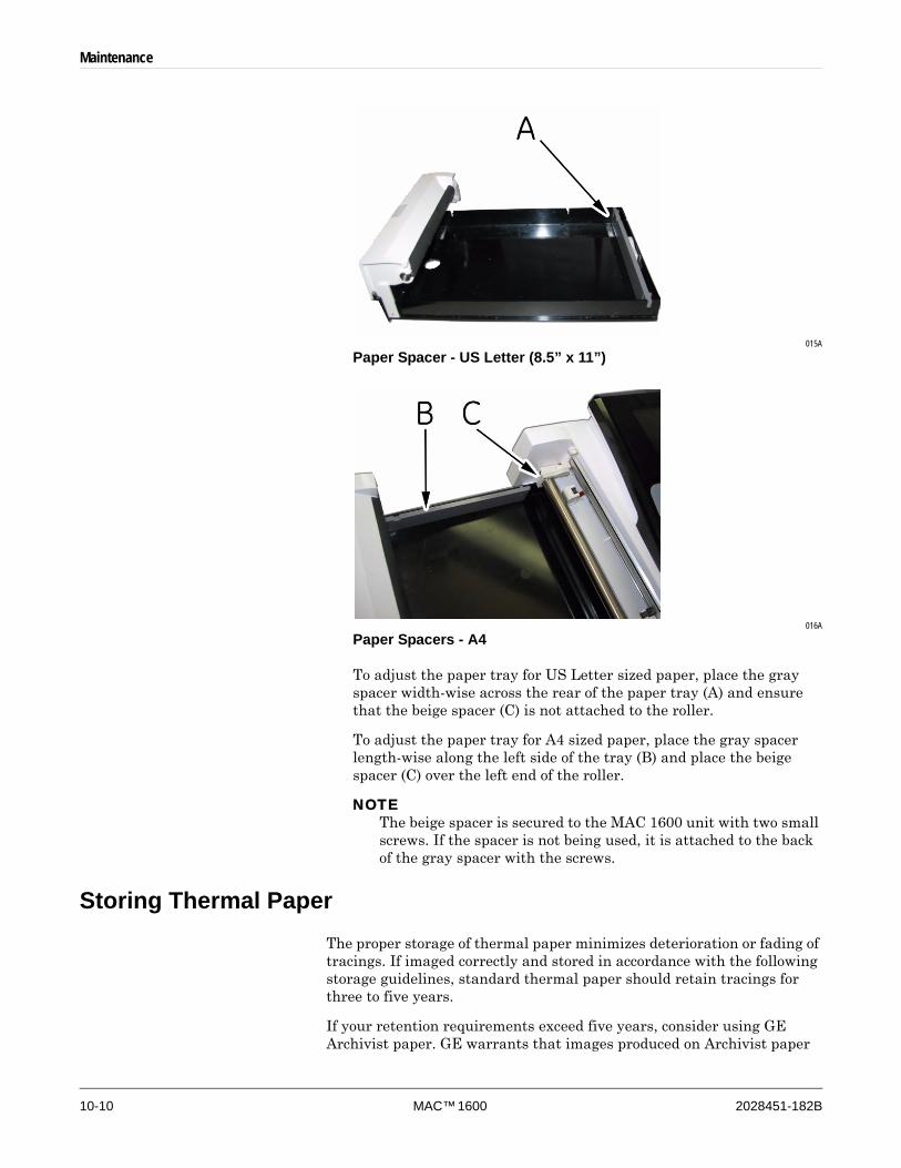
10-10 MAC™ 1600 2028451-182B
Maintenance
015A
Paper Spacer - US Letter (8.5” x 11”)
016A
Paper Spacers - A4
To adjust the paper tray for US Letter sized paper, place the gray spacer width-wise across the rear of the paper tray (A) and ensure that the beige spacer (C) is not attached to the roller.
To adjust the paper tray for A4 sized paper, place the gray spacer length-wise along the left side of the tray (B) and place the beige spacer (C) over the left end of the roller.
NOTEThe beige spacer is secured to the MAC 1600 unit with two small screws. If the spacer is not being used, it is attached to the back of the gray spacer with the screws.
Storing Thermal PaperThe proper storage of thermal paper minimizes deterioration or fading of tracings. If imaged correctly and stored in accordance with the following storage guidelines, standard thermal paper should retain tracings for three to five years.
If your retention requirements exceed five years, consider using GE Archivist paper. GE warrants that images produced on Archivist paper

Maintenance
2028451-182B MAC™ 1600 10-11
will not fade for seven years if (a) the following storage guidelines are observed and (b) the GE equipment used is maintained in accordance with the equipment’s service manuals and memoranda. If fading occurs, notify GE promptly.
If your retention requirements exceed seven years, consider alternate storage methods.
Use the following guidelines for storing thermal paper.
Keep the paper cool and dry, according to the following guidelines.
Standard paper
Temperature: less than 27°C (80°F)
Archivist paper
Temperature: less than 40° C (104°F).
Relative humidity: between 40% and 60%.
Avoid exposure to bright light or ultraviolet sources.
Sunlight, fluorescent lights, and similar lighting cause yellowing of paper and fading of tracings.
Avoid contact with cleaning fluids and solvents, such as alcohols, ketones, esters, ether, and so on.
Avoid mounting forms, pressure-sensitive tapes, and labels that use solvent-based adhesives.
Use only products with starch- or water-based adhesives.
Keep the paper separate from the following:
carbon and carbonless forms
non-thermal chart papers
any products containing tributyl phosphate, dibutyl phthalate, or any other organic solvents (often contained in medical and industrial charts)
Keep the paper in a manila folder or a polyester/polyimide protector.
Avoid plastic document protectors, envelopes, or sheet separators made of polystyrene, polypropylene, polyethylene, polyvinyl chloride, or other vinyl chlorides. Although they will not degrade thermal traces in themselves, they afford no protection against fading from external causes.
Battery MaintenanceThe MAC 1600 ECG Analysis System uses a rechargeable battery containing lithium-ion cells. The battery contains an integrated electronic fuel gauge and a safety protection circuit.
Because of the bias current needed to operate the integrated electronics, the battery will discharge even when it is not installed in the device. The rate at which it discharges is dependent on the ambient temperature at which it is stored. The higher the temperature, the more quickly it
10-12 MAC™ 1600 2028451-182B
Maintenance
discharges. To prolong the battery’s charge when not in use, store the battery in a cool, dry location.
A new, fully-charged battery should last for approximately 3 hours of normal operation. An on-screen LED indicates the condition and capacity of the battery’s charge. (For more information on the battery gauge, refer to “Front View” on page 2-2 and “System Errors” on page A-7). When the LED flashes amber, connect the MAC 1600 system to AC power to charge the battery to full capacity.
As the battery ages, the full charge capacity of the battery will degrade and be permanently lost. As a result, the amount of charge that is stored and available for use is reduced. When the capacity is no longer sufficient for your daily operation, you will need to replace the battery.
Battery SafetyObserve the following warnings whenever handling the MAC 1600 battery.
WARNINGEXPLOSION OR FIRE — Using non-recommended batteries could result in injury/burns to patients or users and may void the warranty.
Use only batteries recommended or manufactured by GE.
WARNINGPHYSICAL INJURY — Leaks from battery cells can occur under extreme conditions. The liquid is caustic to eyes and skin.
If the liquid comes in contact with eyes, skin, or clothing, flush with clean water and seek medical attention.
WARNINGBATTERY PACK DISPOSAL — Do NOT dispose of the battery by fire or burning.
Follow local environmental guidelines concerning disposal and recycling.
Replacing the BatteryWhen the battery’s full-charge capacity can no longer operate the MAC 1600 device for an adequate length of time, use the following instructions to replace the battery.

Maintenance
2028451-182B MAC™ 1600 10-13
059A
1. Press down on the paper tray release button, pull up on the roller holder, and pull the paper tray until it stops.
2. Press and hold the release button on the bottom of the device and pull the paper tray to remove it completely from the device.
3. Locate the battery compartment on the bottom of the device, press down on the battery release, and lift the battery from the compartment.
4. Insert the new battery and press down until the battery snaps into place.
The battery has two flanges that fit two recesses at the end of the battery compartment. Insert the flanges into the recesses then tilt the battery into place.
5. Turn the MAC 1600 device right-side up and firmly press the paper tray assembly until it snaps back into position.
Conditioning the MAC 1600 Battery Pack
To maintain the storage capacity of the battery installed in the MAC 1600 unit, GE recommends that you condition the battery once every 6 months to recalibrate its electronic fuel gauge. A condition cycle consists of an uninterrupted “charge-discharge-charge” cycle.
Use the following instructions to condition the MAC 1600 battery.
1. Insert the battery into a MAC 1600 unit that is not being used to record patient tests.

10-14 MAC™ 1600 2028451-182B
Maintenance
For details, refer to “Replacing the Battery” on page 10-12.
2. Disconnect the AC mains power from the MAC 1600 unit.
3. Enter the Battery Status Service Diagnostic window.
4. Allow the battery to discharge until its Charge Level is less than 90%.
5. Turn off the unit and reconnect the AC mains power.
6. Allow the battery to fully charge.
The Battery LED will be solid amber while it is charging and turn off when charging is complete.
7. Remove the AC mains power and turn on the MAC 1600 unit.
8. Allow the battery to discharge until MAC 1600 unit shuts down.
9. Reconnect the AC mains power to the MAC 1600 unit and leave the unit turned off.
10. Allow the battery to fully charge.
When the Battery LED indicator stops flashing and turns solid, the battery is fully charged and the conditioning cycle is complete.
Supplies and AccessoriesFor a list of available supplies and accessories for the MAC 1600 ECG Analysis System, refer to the MAC 1600 ECG Analysis System Service Manual (2028451-182).

2028451-182B MAC™ 1600 A-1
A Troubleshooting

A-2 MAC™ 1600 2028451-182B
Troubleshooting
General Troubleshooting TipsThe following general troubleshooting tips can be used to help diagnose problems not specifically discussed elsewhere in this chapter.
Thoroughly inspect the equipment.
Disconnected or loose cables, missing hardware, and damaged equipment can cause what may appear to be unrelated symptoms or equipment failure.
For additional information, refer to “Inspecting the Equipment” on page 10-3.
Verify the equipment has not been modified.
Unauthorized modifications to the equipment may cause unexpected results, poor performance, or system failure.
If the equipment has had unauthorized modifications, contact GE Technical Support.
Verify the software has not been updated.
Updated software may change system functionality. If the user is unaware of the changes, they may appear as unexpected results.
If the software has been updated, refer to the revised Operator’s Manual to determine whether the update changed features.
Verify whether there have been changes in the equipment’s location or environment that could cause the failure.
For example, equipment that emits radio waves could cause interference during acquisition.
If the environment or location has changed, try using the equipment in the original location to determine whether the problem persists.
Verify the problem was not caused by operator error.
Repeat the scenario and compare that to the operation as described in the manual. If the operator deviated from the manual, repeat the task using the instructions as written.
If these steps do not resolve the problem, refer to the following section for specific problems and solutions. If the problem still cannot be resolved, contact GE Technical Support.
Equipment ProblemsThe following issues are discussed in the remainder of this chapter.
“System Will Not Power Up” on page A-3
“ECG Data Contains Noise” on page A-3
“ACI-TIPI Statement is Not Included on Report” on page A-4
“No BP Readings from Ergoline 900 Ergometer” on page A-4
“External Device Does Not Move” on page A-4
“Cannot Export to Shared Directories” on page A-6

Troubleshooting
2028451-182B MAC™ 1600 A-3
System Will Not Power UpIf the system will not power up, do the following:
Verify the unit is turned on.
If it is not, turn the unit on. Refer to “Turning on the System” on page 2-11 for instructions.
Verify the battery is installed and charged.
Refer to “System Errors” on page A-7 for instructions on verifying whether the battery is installed and charged.
Refer to “Replacing the Battery” on page 10-12 for instructions on installing the battery.
Verify the unit is connected to an AC power outlet.
Refer to “Connecting the AC Power Adapter” on page 2-8 for instructions.
Verify the equipment is receiving power from the outlet.
If the unit is receiving power, the Power LED will be lit.
ECG Data Contains NoiseIf the acquired ECG data displays unacceptable noise levels, do the following:
Check the patient’s position.
The patient should remain motionless during the acquisition of a resting ECG.
Use the Hookup Advisor indicator to help determine the cause of the noise.
For more information, refer to “Hookup Advisor Module” on page 5-12
Verify the electrodes are placed properly.
Refer to “Applying the Electrodes” on page 3-3 for information on proper electrode placement.
Verify the electrodes have been applied correctly.
Perspiration, excessive hair, lotions, and dead skin cells must be removed from the electrode site.
Refer to “Prepare the Patient’s Skin” on page 3-2 more information.
Check for defective or expired electrodes.
Replace the electrodes if there are any questions about their effectiveness.
Check for defective, broken, or disconnected leadwires.
Replace the leadwires if there are any questions about their effectiveness. Refer to “Connecting Leadwires” on page 2-9.
Consider using filters, ADS, and FRF to help eliminate or reduce ECG noise.
For more information, refer to “ECG Options” on page 5-4, “Arrhythmia Options” on page 6-3, or “Stress Options” on page 7-6.
A-4 MAC™ 1600 2028451-182B
Troubleshooting
ACI-TIPI Statement is Not Included on ReportIf the ACI-TIPI statement does not appear when expected, do the following:
Verify the ACI-TIPI option is activated.
For information on activating the ACI-TIPI option, refer to “Options Setup” on page 9-29.
Verify ACI-TIPI is enabled on the ECG.
For information, refer to “Resting ECG Setup” on page 9-6.
Verify the ACI-TIPI required information was entered.
The ACI-TIPI statement will print only if the patient’s gender, date of birth, and chest pain indication are included in the patient information.
Verify the patient is 16 or older.
The ACI-TIPI statement will not print for pediatric patients.
Verify the original ECG was acquired in an electrocardiograph with the ACI-TIPI option.
If you attempt to print an ECG that was imported from an external device, the MAC 1600 device will not generate an ACI-TIPI statement; it will print only if the statement was saved as part of the ECG.
No BP Readings from Ergoline 900 ErgometerIf blood pressure readings were not taken when expected, do the following:
Verify the device is supported.
For a list of supported devices, refer to “Connecting External Devices (Stress Option)” on page 2-10.
Verify the device is connected to the MAC 1600 unit.
External stress devices connect to the MAC 1600 unit via a serial cable. For more information, refer to “Back View” on page 2-3.
Verify the protocol is set up to take blood pressure.
For more information, refer to “Editing Stress Protocols” on page 9-16.
Verify the device is set up correctly to acquire blood pressure.
Refer to the product documentation that accompanied the device.
External Device Does Not MoveIf the external device does not move automatically when expected, do the following:
Verify the correct device is selected in Basic Setup.
For more information, refer to “Basic Setup” on page 9-2.
Troubleshooting
2028451-182B MAC™ 1600 A-5
Verify the selected device is supported.
For a list of supported devices, refer to “Connecting External Devices (Stress Option)” on page 2-10.
Verify the device is connected to the MAC 1600 unit.
External stress devices connect to the MAC 1600 unit via a serial cable. For more information, refer to “Back View” on page 2-3.
Verify the protocol is set up to activate the device.
The protocol can be set up to set the device’s speed and grade or load. For more information, refer to “Editing Stress Protocols” on page 9-16.
Verify the Stop TM button is not depressed.
For more information, refer to “Stress Test Keys” on page 7-5.
Paper JamsIf the paper jams while printing, do the following:
Verify the paper was inserted correctly.
For details, refer to “Replacing Paper” on page 10-8.
Verify the paper tray spacers are set appropriately for the paper size.
For details, refer to “Adjusting the Paper Tray for Paper Size” on page 10-9.
SD Card Not PresentIf you receive an error message stating that the SD card is not present or cannot be found, do the following:
Verify an SD card is inserted into the card slot on the back of unit.
For details, refer to “Back View” on page 2-3.
Verify the SD card is seated firmly.
The SD card will click into place when seated firmly.
Verify the SD card is formatted for a FAT or FAT16 file system.
To verify an SD card is formatted for the correct file system, do the following:
1. Insert the card into an SD card reader attached to a PC.
2. Copy any files you want to save from the SD card to a folder on the PC.
3. Using the Windows Format command, specify either FAT or FAT16 for the file system and format the card.
NOTE
Formatting the SD card will erase any existing files on the card.
4. Copy the files from the folder on the PC to the newly formatted SD card.

A-6 MAC™ 1600 2028451-182B
Troubleshooting
Cannot Import or Transmit Records Via ModemIf you receive an error while attempting to import or transmit ECG records via modem, do the following:
Verify the correct communication option has been activated.
The MAC 1600 system supports two options for communicating via modem: MODC (for communicating with a CardioSoft system) and MODM (for communicating with a MUSE system). For more information, refer to “Options Setup” on page 9-29.
Verify the modem is connected to an analog telephone line using a standard RJ11 phone jack.
For more information, refer to “Back View” on page 2-3.
For external modems, verify the modem is the Multitech MT5634ZBA Global Modem (PN 2004831-001)
For external modems, verify the modem is connected to the MAC 1600 unit with one of the following cables:
350MM MAC 1200 Modem Cable (2008683-001)
1M MAC 1200 Modem Cable (2008683-002)
The cable must be connected to COMM B on the back of the unit. For details, refer to “Back View” on page 2-3.
For external modems, verify the modem is powered on.
An external modem may be powered using either of the following methods:
Externally
Verify the unit is plugged into an AC outlet.
Internally
Verify that Power For External Modem is enabled on Basic Setup (see “Basic Setup” on page 9-2).
Check Communications Setup to:
Verify the correct modem type is selected.
Verify the correct dialing method is selected and configured accurately.
For details, refer to “Communication Setup” on page 9-19.
If transmitting records, check the selected location to:
Verify Modem is the selected device.
Verify the Phone Number is correct.
Verify the correct Protocol is selected.
For details, refer to “Communication Setup” on page 9-19.
Cannot Export to Shared DirectoriesTo resolve errors received while attempting to export ECG records to a shared directory, do the following:
Verify the LANC communication option has been activated.
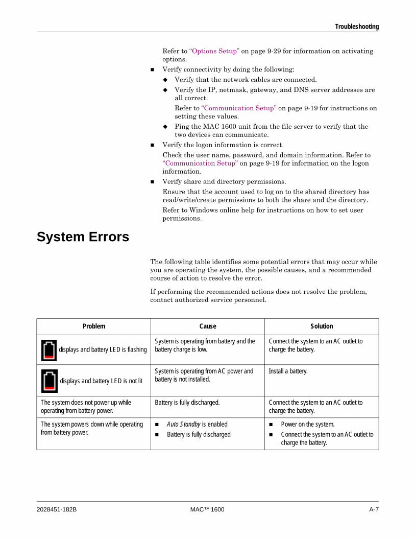
Troubleshooting
2028451-182B MAC™ 1600 A-7
Refer to “Options Setup” on page 9-29 for information on activating options.
Verify connectivity by doing the following:
Verify that the network cables are connected.
Verify the IP, netmask, gateway, and DNS server addresses are all correct.
Refer to “Communication Setup” on page 9-19 for instructions on setting these values.
Ping the MAC 1600 unit from the file server to verify that the two devices can communicate.
Verify the logon information is correct.
Check the user name, password, and domain information. Refer to “Communication Setup” on page 9-19 for information on the logon information.
Verify share and directory permissions.
Ensure that the account used to log on to the shared directory has read/write/create permissions to both the share and the directory.
Refer to Windows online help for instructions on how to set user permissions.
System ErrorsThe following table identifies some potential errors that may occur while you are operating the system, the possible causes, and a recommended course of action to resolve the error.
If performing the recommended actions does not resolve the problem, contact authorized service personnel.
Problem Cause Solution
displays and battery LED is flashingSystem is operating from battery and the battery charge is low.
Connect the system to an AC outlet to charge the battery.
displays and battery LED is not litSystem is operating from AC power and battery is not installed.
Install a battery.
The system does not power up while operating from battery power.
Battery is fully discharged. Connect the system to an AC outlet to charge the battery.
The system powers down while operating from battery power.
Auto Standby is enabled Battery is fully discharged
Power on the system.Connect the system to an AC outlet to charge the battery.
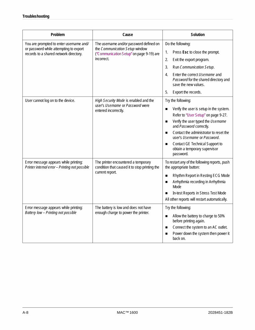
A-8 MAC™ 1600 2028451-182B
Troubleshooting
You are prompted to enter username and/or password while attempting to export records to a shared network directory.
The username and/or password defined on the Communication Setup window (“Communication Setup” on page 9-19) are incorrect.
Do the following:
1. Press Esc to close the prompt.
2. Exit the export program.
3. Run Communication Setup.
4. Enter the correct Username and Password for the shared directory and save the new values.
5. Export the records.
User cannot log on to the device. High Security Mode is enabled and the user’s Username or Password were entered incorrectly.
Try the following:
Verify the user is setup in the system.Refer to “User Setup” on page 9-27.Verify the user typed the Username and Password correctly. Contact the administrator to reset the user’s Username or Password. Contact GE Technical Support to obtain a temporary supervisor password.
Error message appears while printing: Printer internal error – Printing not possible
The printer encountered a temporary condition that caused it to stop printing the current report.
To restart any of the following reports, push the appropriate button:
Rhythm Report in Resting ECG ModeArrhythmia recording in Arrhythmia ModeIn-test Reports in Stress Test Mode
All other reports will restart automatically.
Error message appears while printing: Battery low – Printing not possible
The battery is low and does not have enough charge to power the printer.
Try the following:
Allow the battery to charge to 50% before printing again.Connect the system to an AC outlet. Power down the system then power it back on.
Problem Cause Solution

2028451-182B MAC™ 1600 B-1
B Creating Barcodes
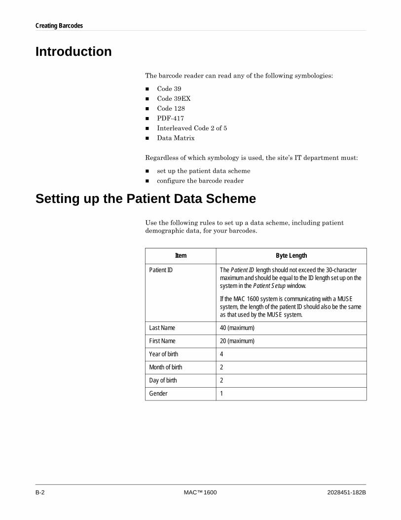
B-2 MAC™ 1600 2028451-182B
Creating Barcodes
IntroductionThe barcode reader can read any of the following symbologies:
Code 39
Code 39EX
Code 128
PDF-417
Interleaved Code 2 of 5
Data Matrix
Regardless of which symbology is used, the site’s IT department must:
set up the patient data scheme
configure the barcode reader
Setting up the Patient Data SchemeUse the following rules to set up a data scheme, including patient demographic data, for your barcodes.
Item Byte Length
Patient ID The Patient ID length should not exceed the 30-character maximum and should be equal to the ID length set up on the system in the Patient Setup window.
If the MAC 1600 system is communicating with a MUSE system, the length of the patient ID should also be the same as that used by the MUSE system.
Last Name 40 (maximum)
First Name 20 (maximum)
Year of birth 4
Month of birth 2
Day of birth 2
Gender 1

Creating Barcodes
2028451-182B MAC™ 1600 B-3
Configuring the Barcode ReaderThe barcode reader is configured on the MAC 1600 Patient Setup window. You can choose to configure it manually or automatically. The requirements for each method are described in the following sections. For instructions on configuring the barcode reader, refer to “Patient Setup” on page 9-24.
Configuring the Barcode Reader ManuallyTo configure the barcode reader manually, you will need to enter the following information on the MAC 1600 Patient Setup window.
Field Number of bytes
Total number of bytes ________
Patient ID offset ________
Patient ID length ________
First name offset ________
First name length ________
Last name offset ________
Last name length ________
Year of birth offset ________
Year of birth length ________
Month of birth offset ________
Month of birth length ________
Day of birth offset ________
Day of birth length ________
Gender offset ________
Gender length ________
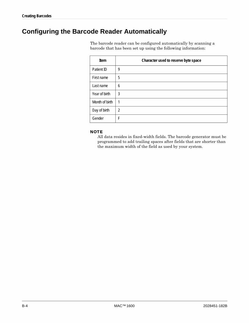
B-4 MAC™ 1600 2028451-182B
Creating Barcodes
Configuring the Barcode Reader AutomaticallyThe barcode reader can be configured automatically by scanning a barcode that has been set up using the following information:
NOTEAll data resides in fixed-width fields. The barcode generator must be programmed to add trailing spaces after fields that are shorter than the maximum width of the field as used by your system.
Item Character used to reserve byte space
Patient ID 9
First name 5
Last name 6
Year of birth 3
Month of birth 1
Day of birth 2
Gender F
2028451-182B MAC™ 1600 Index-1
Index
IndexNumerics
12 Lead Display for Resting ECG ......................... 9-3012 Lead Display for Stress Test ............................ 9-3012SL Measurement............................................... 9-3012SL Measurement and Interpretation ................. 9-3021 CFR Part 11 Audit Trail .................................... 9-30
AA (artifact) ............................................................... 6-5AC power, connecting to......................................... 2-8accessories
and parts......................................................... 1-12recommended................................................. 1-12
ACI-TIPIincluding ......................................................... 9-10option.............................................................. 9-30
acquisition cableconnector.......................................................... 2-3types ................................................................. 2-6
Acute Cardiac Ischemia-Time Insensitive Predictive Instrument, see ACI-TIPI
Adenosine (protocol) ............................................. 9-16ADS
definition .................................................. 6-4, 9-14on arrhythmia setup................................. 9-7, 9-12on stress ECG setup ...................................... 9-14turn off during defibrillation ............................. 1-11
Allow Export Using Shared Directory .................... 9-20Anti-Drift System, see ADSarrhythmia codes .................................................... 6-5Arrhythmia ECG
display .............................................................. 6-2mode................................................................. 6-2options .............................................................. 6-3printing an arrhythmia report ............................ 6-2printing options ................................................. 6-5
Arrhythmia Event Printing ..................................... 9-13Arrhythmia Setup
ADS ......................................................... 9-7, 9-12episode printout .............................................. 9-13event printing .................................................. 9-13lead sequence ................................................ 9-13overview ......................................................... 9-12
artifact ..................................................................... 6-5ASYSTO (asystole) ................................................. 6-5asystole................................................................... 6-5Audit Trail ................................................................ 9-5auto configuring a barcode reader ........................ 9-27Auto Logoff.............................................................. 9-5Auto Standby .......................................................... 9-4Auto Store ECG .................................................... 9-11
Auto Transmit ECG............................................... 9-11
BBal (protocol)......................................................... 9-17Balkeware (protocol) ............................................. 9-16barcode reader
configuring ...................................................... 9-27connecting to .................................................. 2-10entering patient information .............................. 4-3option.............................................................. 9-30settings ........................................................... 9-27
baseline shift, reducing ........................................... 6-4Basic Setup
audit trail ........................................................... 9-5auto logoff......................................................... 9-5auto standby ..................................................... 9-4high security mode ........................................... 9-5overview ........................................................... 9-2power for external modems .............................. 9-4power up mode................................................. 9-4selecting test device ......................................... 9-4time synchronization......................................... 9-5
batterycharging............................................................ 2-8inserting ........................................................ 10-12LED................................................................... 2-2lithium-ion ......................................................... 2-8maintenance ................................................. 10-11replacing ....................................................... 10-12safety ............................................................ 10-12
BCRD option ................................................ 2-10, 9-30biocompatibility statement..................................... 1-10Blood Pressure Unit .............................................. 9-24Bruce (protocol) .................................................... 9-16
CCardiogoraph Device Name.................................. 9-22CardioSoft system
communication option..................................... 9-30Cardiosoft system
importing from................................................... 8-3CDTG option ......................................................... 9-30CFRA option .................................................. 9-5, 9-30CISPR 11 ................................................................ 1-8cleaning
disinfectant to use........................................... 10-5disinfecting leadwires ..................................... 10-6leadwires ........................................................ 10-6materials to avoid .................................. 10-3, 10-5materials to use ..................................... 10-3, 10-4sterilizing leadwires ........................................ 10-7
Index
Index-2 MAC™ 1600 2028451-182B
communication protocol ........................................ 9-21Communication Setup
cardiogoraph device name ............................. 9-22default location ............................................... 9-19device ............................................................. 9-21DHCP settings ................................................ 9-22DNS settings................................................... 9-23location ........................................................... 9-20modem settings .............................................. 9-21overview ......................................................... 9-19protocol........................................................... 9-21serial baud rate............................................... 9-20shared directory settings ................................ 9-20
CONCONI (protocol) ............................................. 9-17configurations, switching between ........................ 9-32connecting
to a barcode reader ........................................ 2-10to a modem..................................................... 2-10to AC power...................................................... 2-8to external devices.......................................... 2-10to leadwires ...................................................... 2-9
conventions............................................................. 1-2Cornell (protocol) .................................................. 9-16Country Setup
blood pressure unit ......................................... 9-24date format ..................................................... 9-23height/weight unit............................................ 9-23language......................................................... 9-23overview ......................................................... 9-23speed unit ....................................................... 9-23ST Level unit................................................... 9-24time format...................................................... 9-23
CPLT (ventricular couplet) ...................................... 6-5CT Data Guard...................................................... 9-30CTDG option ........................................................... 4-2
Ddate format ............................................................ 9-23Date Setup ............................................................ 9-31daylight savings time............................................. 9-31Default Location .................................................... 9-19defibrillation
electrodes to use during ................................. 1-11recording an ECG during....................... 1-11, 5-13turn off ADS during ......................................... 1-11turn off FRF during ......................................... 1-11
deleting records ...................................................... 8-6DHCP settings ...................................................... 9-22disinfectant to use ................................................. 10-5Display Format ........................................................ 9-8Display Lead Group ................................................ 9-8DNS settings ......................................................... 9-23Dobutamine (protocol) .......................................... 9-16Dose List ............................................................... 9-27Dose Type............................................................. 9-27
EE12L option........................................................... 9-30eBike ergometer.................................................... 2-11ECG
deleting ............................................................. 8-6editing patient information ................................ 8-5exporting........................................................... 8-8finding ............................................................... 8-4importing........................................................... 8-3printing.............................................................. 8-7recording during defibrillation ................ 1-11, 5-13transmitting ....................................................... 8-7see also
Arrhythmia ECGResting ECGStress ECG
ECG Filter Type .................................................... 9-14ECG reanalysis
conducting ........................................................ 5-8display .............................................................. 5-9generating......................................................... 5-8options ............................................................ 5-10setup................................................................. 9-9
editing patient information....................................... 8-5EFUP (Environment-friendly Use Period) ............. 1-13electrodes
12 Lead placement .................................... 3-4, 3-6NEHB placement .............................................. 3-5to use during defibrillation............................... 1-11
Ellestad (protocol) ................................................. 9-16Enabling Patient ID Check .................................... 9-25Episode Printout.................................................... 9-13equipment
identification.................................................... 1-15safety information ............................................. 1-3service requirements ...................................... 1-15type BF ........................................................... 1-13
equipotentional grounding lug................................. 2-4ERGO option.................................... 7-3, 9-2, 9-4, 9-30Ergoline ergometer ............................................... 2-11ergometer
conducting a stress test with ............................ 7-8eBike............................................................... 2-11Ergoline .......................................................... 2-11Excalibur......................................................... 2-11supported models ............................................. 7-2unsupported models ......................................... 7-2Variobike......................................................... 2-11with remote start ............................................... 7-2
ESC (ventricular escape beat) ................................ 6-5ethylene oxide gas ................................................ 10-7EtO........................................................................ 10-7Excalibur ergometer.............................................. 2-11Export Setup ......................................................... 9-33
2028451-182B MAC™ 1600 Index-3
Index
export XML............................................................ 9-20exporting ECG records ........................................... 8-8external devices
connecting to .................................................. 2-10eBike............................................................... 2-11Ergoline ergometer ......................................... 2-11Excalibur......................................................... 2-11Master’s Step.................................................. 2-11supported models ............................................. 7-2T2100 treadmill ............................................... 2-10Trackmaster TMX425 ..................................... 2-11unsupported models ......................................... 7-2Variobike......................................................... 2-11
Extra Questions .................................................... 9-27
Ffiducial points ........................................................ 5-10File Manager
deleting records ................................................ 8-6editing patient information ................................ 8-5exporting records.............................................. 8-8finding records .................................................. 8-4importing records.............................................. 8-3overview ........................................................... 8-2printing directory ............................................... 8-4printing records................................................. 8-7transmitting records .......................................... 8-7
filter .................................................................. 5-5, 6-4finding ECG records................................................ 8-4Finite Residual Filter, see FRFfrequency response .............................................. 1-12FRF
definition ......................................................... 9-14on stress ECG setup ...................................... 9-14turn off during defibrillation ............................. 1-11
function keys ........................................................... 2-4
Ggain .................................................... 5-5, 6-4, 7-7, 9-6grounding ................................................................ 2-4
HHEART Resting Measurement.............................. 9-30HEART Resting Measurement and Interpretation 9-30Height/Weight Unit ................................................ 9-23High Pass Filter....................................................... 9-7High Security Mode................................................. 9-5Hollmann (protocol)............................................... 9-17Hookup Advisor module
affected by skin preparation ............................. 3-2overview ......................................................... 5-12setting up .......................................................... 9-8
IImport Setup ......................................................... 9-34importing ECG records ........................................... 8-3
input signal accuracy ............................................ 1-12inspecting a MAC 1600 device ............................. 10-3intended use ......................................................... 1-10internal storage, see File Manager
JJ+x Point Formula ................................................. 9-15
KKanji name ............................................................ 9-24keyboard
layout ................................................................ 2-4stress layout ..................................................... 7-5using ............................................................... 2-12
KISScleaning instructions ....................................... 10-4connector.......................................................... 2-3
LL (learn phase)........................................................ 6-6LAN Communication to CardioSoft ....................... 9-30LAN Communication to MUSE.............................. 9-30LANC option................................................... 8-8, 9-30LANM option ......................................................... 9-30Lead Sequence............................................ 9-10, 9-13leadwire
adapters............................................................ 2-7cleaning .......................................................... 10-6connecting to .................................................... 2-9replacing adapters .......................................... 10-7sanitizing......................................................... 10-7storing............................................................. 10-7
learn phase ............................................................. 6-6lithium-ion battery, see batteryLocation ................................................................ 9-20Low Pass Filter .............................................. 9-7, 9-14
MM100 option ................................................... 8-2, 9-30maintenance
cleaning leadwires .......................................... 10-6cleaning MAC 1600 surfaces.......................... 10-3cleaning materials to avoid .................... 10-3, 10-5cleaning materials to use....................... 10-3, 10-4disinfectant to use........................................... 10-5disinfecting leadwires ..................................... 10-6inspecting a MAC 1600 device ....................... 10-3overview ......................................................... 10-2replacing leadwire adapters............................ 10-7sterilizing leadwires ........................................ 10-7storing leadwires............................................. 10-7
Master’s Stepconducting a stress test with .......................... 7-11mode............................................................... 9-15overview ........................................................... 7-2selecting ......................................................... 9-15
Index
Index-4 MAC™ 1600 2028451-182B
Maximum Predicted HR Formula.......................... 9-14ME12 option.......................................................... 9-30MEHR option......................................................... 9-30menu options
selecting ......................................................... 2-12MI12 option ........................................................... 9-30MIHR option .......................................................... 9-30ModBalke (protocol) .............................................. 9-16ModBalkeware (protocol) ...................................... 9-16ModBruce (protocol) ............................................. 9-16MODC option ................................................. 9-30, A-6modem
connecting to ........................................... 2-10, 8-7powered by the MAC 1600 unit ........................ 9-4settings ........................................................... 9-21troubleshooting ................................................. A-6
Modem or serial communication to CardioSoft ..... 9-30Modem or serial communication to MUSE............ 9-30MODM option................................................. 9-30, A-6ModWHO (protocol) .............................................. 9-17Multi-Link acquisition cable ..................................... 2-7MUSE system
communication option..................................... 9-30importing from................................................... 8-3User ID ........................................................... 9-28
NNaughton (protocol) .............................................. 9-16navigating with the trimpad ................................... 2-13
Ooption
BCRD .................................................... 2-10, 9-30CDTG ............................................................. 9-30CFRA....................................................... 9-5, 9-30CTDG ............................................................... 4-2E12L ............................................................... 9-30ERGO........................................ 7-3, 9-2, 9-4, 9-30LANC ....................................................... 8-8, 9-30LANM.............................................................. 9-30M100........................................................ 8-2, 9-30ME12 .............................................................. 9-30MEHR ............................................................. 9-30MI12................................................................ 9-30MIHR .............................................................. 9-30MODC...................................................... 9-30, A-6MODM ..................................................... 9-30, A-6R12L ............................................................... 9-30setup............................................................... 9-29TIPI ................................................................. 9-30
Ppacemaker
capture code..................................................... 6-6improving ECG readability........... 5-5, 6-5, 7-8, 9-8
malfunction ....................................................... 6-6recording ECGs of patients with ..................... 5-13
paperadjusting tray size for...................................... 10-9problems with ................................................... A-5replacing ......................................................... 10-8storing........................................................... 10-10troubleshooting problems with.......................... A-5
parts and accessories ........................................... 1-12patient
editing information with File Manager............... 8-5setup
auto configure .......................................... 9-27barcode reader settings ........................... 9-27custom fields ................................... 9-26, 9-27dose list .................................................... 9-27dose type ................................................. 9-27enabling ID check .................................... 9-25extra questions................................ 9-26, 9-27ID type...................................................... 9-25Kanji name ............................................... 9-24overview................................................... 9-24
skin preparation ................................................ 3-2Patient ID Type ..................................................... 9-25patient information
entering manually ............................................. 4-2entering with a barcode reader......................... 4-3
PAU1 (pause of 1 missed beat) .............................. 6-6PAU2 (Pause of 2 missed beats)............................ 6-6pause
1 missed beat ................................................... 6-62 missed beats ................................................. 6-6
PCAP (pacemaker capture) .................................... 6-6PERR (pacemaker malfunction) ............................. 6-6Persantine (protocol)............................................. 9-16PIN dialing............................................................. 9-21post-J point ........................................................... 9-15Power Up Mode ...................................................... 9-4Printer Leads........................................................... 9-8printer leads ............................................................ 5-6printing ECG records .............................................. 8-7product code ......................................................... 1-15protocol
communication ............................................... 9-21description ...................................................... 9-17editing ............................................................. 9-16list ................................................................... 9-16selecting ......................................................... 9-15
PSVC (premature supraventricular contraction) ..... 6-6PVC (premature ventricular contraction)................. 6-6
QQRSL (learned QRS complex)................................ 6-6QTC Calculation...................................................... 9-9
2028451-182B MAC™ 1600 Index-5
Index
RR12L option........................................................... 9-30reanalyzing an ECG................................................ 5-8recording a resting ECG ......................................... 5-3Resting ECG
deleting ............................................................. 8-6display .............................................................. 5-2editing patient information ................................ 8-5editing patient information on ........................... 8-5exporting........................................................... 8-8finding ............................................................... 8-4importing........................................................... 8-3mode................................................................. 5-2options .............................................................. 5-4post-acquisition options .................................... 5-6printing.............................................................. 8-7reanalyzing ....................................................... 5-8recording........................................................... 5-3Rhythm Report ................................................. 5-7saving automatically ................................ 8-2, 9-11saving manually................................................ 8-2setup
ACI-TIPI ................................................... 9-10auto store ................................................. 9-11auto transmit ............................................ 9-11display format............................................. 9-8display lead group...................................... 9-8gain ............................................................ 9-6high pass filter ............................................ 9-7Hookup Advisor module ............................. 9-8lead sequence.......................................... 9-10low pass filter ............................................. 9-7overview..................................................... 9-6pace enhancement..................................... 9-8printer leads ............................................... 9-8QTC Calculation......................................... 9-9reanalysis ................................................... 9-9sweep speed.............................................. 9-6
transmitting .............................................. 8-7, 9-11Rhythm Report ........................................................ 5-7RUN (ventricular run) .............................................. 6-6
Ssafety
equipment symbols......................................... 1-13messages ......................................................... 1-3
SD card ......................... 2-4, 2-11, 8-8, 9-33, 9-34, A-5Secure Digital Card, see SD card ........................... 2-4Serial Baud Rate................................................... 9-20serial number
description ...................................................... 1-15where to find ................................................... 1-15
service requirements............................................. 1-15Service Setup, see the MAC 1600 Service ManualSetup Report ......................................................... 9-31
shared directory ............................................. 8-8, 9-20SJ/T11363-2006 ................................................... 1-13skin preparation ...................................................... 3-2SlowUSAFSAM (protocol)..................................... 9-16Speed Unit ............................................................ 9-23sphygmomanometer ............................................. 2-11ST Level unit ......................................................... 9-24Std.France (protocol) ............................................ 9-17Storage for 100 ECGs........................................... 9-30Stress ECG
blood pressure.................................................. 7-4conducting with a ergometer ............................ 7-8conducting with a Master’s Step..................... 7-11conducting with a treadmill ............................... 7-8display .............................................................. 7-3mode................................................................. 7-2options .............................................................. 7-6prerequisites ..................................................... 7-3rate-pressure product ....................................... 7-4report formats ................................................... 7-3selecting the test device ................................... 9-4setup
ADS.......................................................... 9-14ECG filter type.......................................... 9-14FRF .......................................................... 9-14J+x Point Formula .................................... 9-15low pass filter ........................................... 9-14Master’s Step Mode ................................. 9-15maximum predicted heart rate ................. 9-14overview................................................... 9-13protocol .................................................... 9-15target heart rate ....................................... 9-14
target heart rate ................................................ 7-4test information bar........................................... 7-3test keys ........................................................... 7-5VE/min .............................................................. 7-4
stress test information bar....................................... 7-3Stress Test option ................................................. 9-30supraventricular
premature contraction....................................... 6-6sweep speed...................................... 5-4, 6-3, 7-7, 9-6symbols................................................................. 1-13System Setup
Date/Time ....................................................... 9-31exporting......................................................... 9-33importing......................................................... 9-34printing............................................................ 9-31switching configurations ................................. 9-32see also
Arrhythmia ECGBasic SetupCommunication SetupCountry Setupoption, setup
Index
Index-6 MAC™ 1600 2028451-182B
patient, setupResting ECGStress ECGthe MAC 1600 Service ManualUser Setup
TT2000 treadmill ..................................................... 2-11T2100 treadmill ..................................................... 2-10target heart rate ............................................. 7-4, 9-14time format ............................................................ 9-23Time Setup............................................................ 9-31time synchronization ............................................... 9-5TIPI option............................................................. 9-30Trackmaster TMX425 ........................................... 2-11transmitting ECG records........................................ 8-7treadmill
conducting a stress test with ............................ 7-8supported models ............................................. 7-2T2000 ............................................................. 2-11T2100 ............................................................. 2-10unsupported models ......................................... 7-2
trimpaddescription ........................................................ 2-5navigating with................................................ 2-13
troubleshootingbasic questions................................................. A-3operator error.................................................... A-2visual inspection ....................................... A-2, A-3
type BF equipment................................................ 1-13typographical conventions ...................................... 1-2
UUnderwriters Laboratories....................................... 1-9USAFSAM (protocol) ............................................ 9-16USB (Universal Serial Bus)..................................... 2-4USB connector...................................................... 2-10User Setup
MUSE ID......................................................... 9-28overview ......................................................... 9-27
VVariobike ergometer.............................................. 2-11VBIG (ventricular bigeminy) .................................... 6-6ventricular
bigeminy ........................................................... 6-6couplet .............................................................. 6-5ectopics per minute .......................................... 7-4escape beat ...................................................... 6-5fibrillation .......................................................... 6-6premature contraction....................................... 6-6run .................................................................... 6-6tachycardia ....................................................... 6-6
VFIB (ventricular fibrillation/flutter) .......................... 6-6visual inspection...................................................... A-2VTAC (ventricular tachycardia) ............................... 6-6
WWHO (protocol) ..................................................... 9-17WHO50 (protocol) ................................................. 9-17WHO75 (protocol) ................................................. 9-17
XXML export............................................................ 9-20


World HeadquartersGE Medical SystemsInformation Technologies, Inc.8200 West Tower AvenueMilwaukee, WI 53223 USATel: + 1 414 355 5000
1 800 558 5120 (US only)Fax: + 1 414 355 3790
European RepresentativeGE Medical SystemsInformation Technologies GmbHMunzinger Straße 3-5D-79111 FreiburgGermanyTel: + 49 761 45 43 - 0Fax: + 49 761 45 43 - 233
Asia HeadquartersGE Medical SystemsInformation Technologies Asia; GE (China) Co., Ltd.24th Floor, Shanghai MAXDO Center,8 Xing Yi Road, Hong Qiao Development ZoneShanghai 200336, P.R. ChinaTel: + 86 21 5257 4650Fax: + 86 21 5208 2008
www.gehealthcare.com