Embed Size (px)
Citation preview
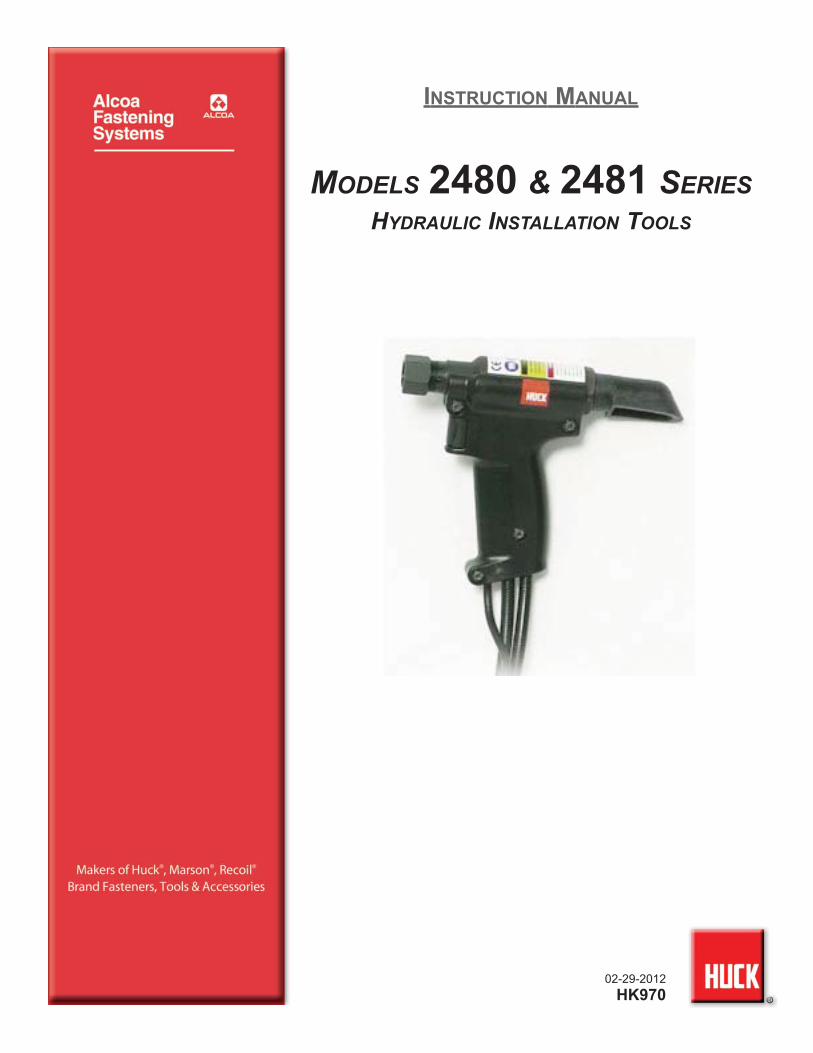
02-29-2012
HK970
INSTRUCTION MANUAL
MODELS 2480 & 2481 SERIESHYDRAULIC INSTALLATION TOOLS
2480 & 2481 series Tooling (HK970) Alcoa Fastening Systems
2
2480 & 2481 series Tooling (HK970) Alcoa Fastening Systems
3
CCONTENTSONTENTS
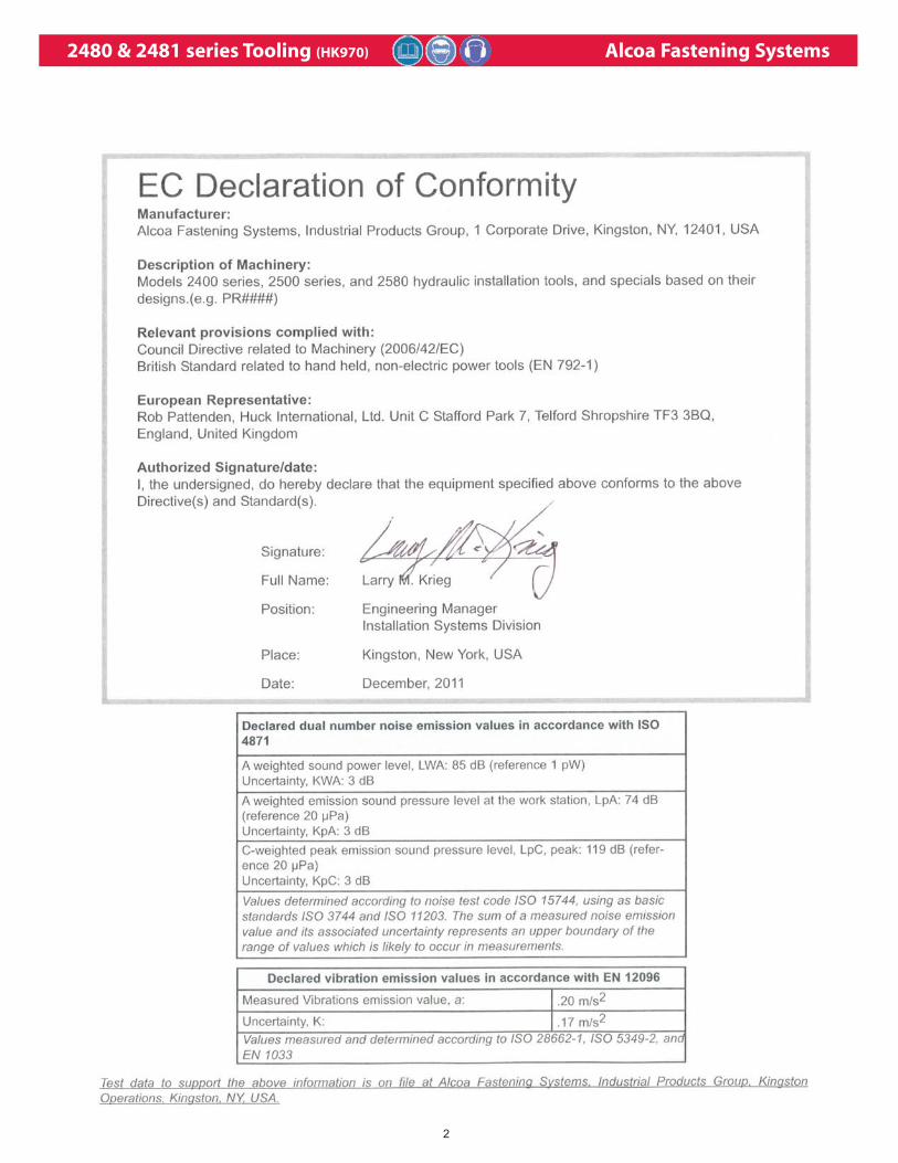
EU Declaration of Conformity . . . . . . . . . . . . . . . . . . . . . . . . . . . . . . . . . .2
Safety` . . . . . . . . . . . . . . . . . . . . . . . . . . . . . . . . . . . . . . . . . . . . . . . . . . . .4
Description . . . . . . . . . . . . . . . . . . . . . . . . . . . . . . . . . . . . . . . . . . . . . . . . .5
Specifications . . . . . . . . . . . . . . . . . . . . . . . . . . . . . . . . . . . . . . . . . . . .5 & 6
Principle of Operation . . . . . . . . . . . . . . . . . . . . . . . . . . . . . . . . . . . . . . . .7
Tool Operation/Installation Sequence . . . . . . . . . . . . . . . . . . . . . . . . . . . .8
Tool Danger Zones . . . . . . . . . . . . . . . . . . . . . . . . . . . . . . . . . . . . . . . . . . .9
Preparation for Use . . . . . . . . . . . . . . . . . . . . . . . . . . . . . . . . . . . . . . . . .10
Operating Instructions . . . . . . . . . . . . . . . . . . . . . . . . . . . . . . . . . . . . . . .11
Maintenance (Good Service Practices) . . . . . . . . . . . . . . . . . . . . . . . . . . . . .12
Maintenance (Preventive Maintenance) . . . . . . . . . . . . . . . . . . . . . . . . . . . . .13
Troubleshooting . . . . . . . . . . . . . . . . . . . . . . . . . . . . . . . . . . . . . . . . . . . .14
Sticker Locations . . . . . . . . . . . . . . . . . . . . . . . . . . . . . . . . . . . . . . . . . . .15
Service Parts Kit . . . . . . . . . . . . . . . . . . . . . . . . . . . . . . . . . . . . . . . . . . . .15
Specifications for Standard Parts . . . . . . . . . . . . . . . . . . . . . . . . . . . . . . .15
Disassembly of Tool . . . . . . . . . . . . . . . . . . . . . . . . . . . . . . . . . . . . .16 - 19
Assembly of Tool . . . . . . . . . . . . . . . . . . . . . . . . . . . . . . . . . . . . . . . .20 - 23
Assembly Drawing W/Part Numbers (2480) . . . . . . . . . . . . . . . . . . . . . .24
Assembly Drawing W/Part Numbers (2480L) . . . . . . . . . . . . . . . . . . . . .25
Assembly Drawing W/Part Numbers (2480L-1) . . . . . . . . . . . . . . . . . . . .26
Assembly Drawing W/Part Numbers (2480L-2) . . . . . . . . . . . . . . . . . . . .27
Assembly Drawing W/Part Numbers (2480XL) . . . . . . . . . . . . . . . . . . . .28
Assembly Drawing W/Part Numbers (2481) . . . . . . . . . . . . . . . . . . . . . .29
Assembly Drawing W/Part Numbers (2481L-1) . . . . . . . . . . . . . . . . . . . .30
Assembly Drawing W/Part Numbers (A2480) . . . . . . . . . . . . . . . . . . . . .31
Assembly Drawing W/Part Numbers (2480LS) . . . . . . . . . . . . . . . . . . . .32
Assembly Drawing W/Part Numbers (2480LSL) . . . . . . . . . . . . . . . . . . .33
Air Trigger & Hose Assembly . . . . . . . . . . . . . . . . . . . . . . . . . . . . . . . . . .34
2480 & 2481 series Tooling (HK970) Alcoa Fastening Systems
4
1. A half hour long hands-on training session with qualified per-
sonnel is recommended before using Huck equipment.
2. Huck equipment must be maintained in a safe working condi-
tion at all times. Tools and hoses should be inspected at the
beginning of each shift/day for damage or wear. Any repair
should be done by a qualified repairman trained on Huck pro-
cedures.
3. Repairman and Operator must read manual prior to using
equipment. Warning and Caution stickers/labels supplied with
equipment must be understood before connecting equipment
to any primary power supply. As applicable, each of the sec-
tions in this manual have specific safety and other information.
4. Read MSDS Specifications before servicing the tool. MSDS
Specifications are available from the product manufacturer or
your Huck representative.
5. When repairing or operating Huck installation equipment,
always wear approved eye protection. Where applicable, refer
to ANSI Z87.1 - 2003
6. Only genuine Huck parts shall be used for replacements or
spares. Use of any other parts can result in tooling damage or
personal injury.
7. If a part affixed with warning labels is replaced, or labels are
missing or damaged, the end user is responsible for replace-
ment. Refer to assembly drawing and parts list for replace-
ment part number and proper placement.
8. Disconnect primary power source before performing mainte-
nance on Huck equipment or changing Nose Assembly.
9. Tools and hoses should be inspected for leaks at the begin-
ning of each shift/day. If any equipment shows signs of dam-
age, wear, or leakage, do not connect it to the primary power
supply.
10. Mounting hardware should be checked at the beginning of
each shift/day.
11. Make sure proper power source is used at all times.
12. Release tool trigger if power supply is interrupted.
13. Tools are not to be used in an explosive environment unless
specifically designed to do so.
14. Never remove any safety guards or pintail deflectors.
15. Where applicable, ensure deflector or pintail collector is
installed and operating prior to use.
16. Never install a fastener in free air. Personal injury from fasten-
er ejecting may occur.
17. Where applicable, always clear spent pintail out of nose
assembly before installing the next fastener.
18. There is possibility of forcible ejection of pintails or spent man-
drels from front of tool.
19. Check clearance between trigger and work piece to ensure
there is no pinch point when tool is activated. Remote triggers
are available for hydraulic tooling if pinch point is unavoidable.
20. Unsuitable postures may not allow counteracting of normal
expected movement of tool.
21. Do not abuse tool by dropping or using it as a hammer. Never
use hydraulic or air lines as a handle or to bend or pry the
tool. Reasonable care of installation tools by operators is an
important factor in maintaining tool efficiency, eliminating
downtime, and in preventing an accident which may cause
severe personal injury.
22. Never place hands between nose assembly and work piece.
Keep hands clear from front of tool.
23. There is a risk of crushing if tool is cycled without Nose
Assembly installed.
24. Tools with ejector rods should never be cycled with out nose
assembly installed.
25. When two piece lock bolts are being used always make sure
the collar orientation is correct. See fastener data sheet for
correct positioning.
26. Tool is only to be used as stated in this manual. Any other use
is prohibited.
27. There is a risk of whipping compressed air hose if tool is pneu-
draulic or pneumatic.
28. Release the trigger in case of failure of air supply or hydraulic
supply.
29. Use only fluids or lubricants recommended.
30. Disposal instruction: Disassemble and recycle steel, aluminum
and plastic parts, and drain and dispose of hydraulic fluid in
accordance with local lawful and safe practices.
31. If tool is fixed to a suspension device, ensure that the device is
secure prior to operating the tool.
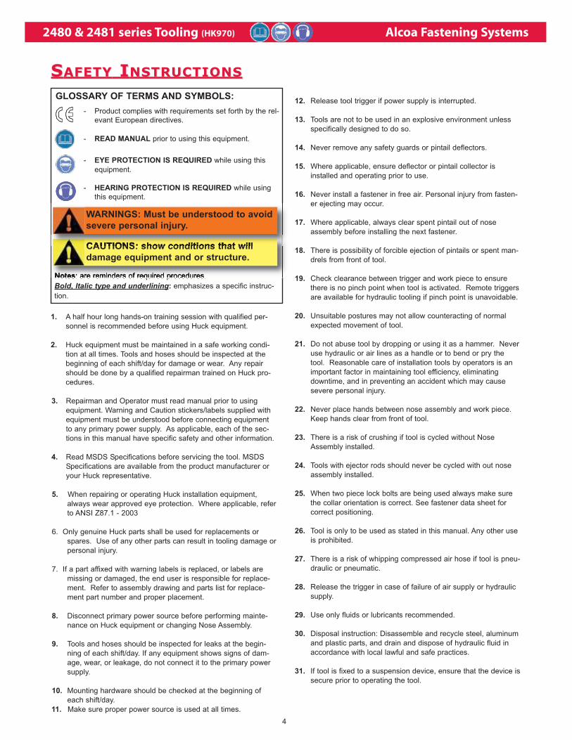
GLOSSARY OF TERMS AND SYMBOLS:
- Product complies with requirements set forth by the rel-
evant European directives.
- READ MANUAL prior to using this equipment.
- EYE PROTECTION IS REQUIRED while using this
equipment.
- HEARING PROTECTION IS REQUIRED while using
this equipment.
Notes: are reminders of required procedures.
Bold, Italic type and underlining: emphasizes a specific instruc-
tion.
SSAFETYAFETY I INSTRUCTIONSNSTRUCTIONS
CAUTIONS: show conditions that will
damage equipment and or structure.
WARNINGS: Must be understood to avoid
severe personal injury.
2480 & 2481 series Tooling (HK970) Alcoa Fastening Systems
5
The 2480, A2480, and 2481 series, with appropriate
nose assemblies, install a wide range of Huck blind
fasteners and HUCKBOLT® fasteners. The 2480
series has hoses that pass through the handle and
2481 has hoses attached to the top of the tool - - see
FIGURE 3 and FIGURE4. These lightweight and com-
pact tools are particularly adapted to installing fasten-
ers in limited clearance areas. Each tool is complete
with hydraulic hoses and couplings; electric switch
and cord. Tool is basically a cylinder aid piston
assembly. An unloading valve, designed to relieve
hydraulic pressure at end of the PULL stroke, is posi-
tioned by the piston. The end of the piston rod is
threaded - - retaining nut and stop are included for
attaching a nose assembly.
Huck Hydraulic Installation Tools are designed to be
powered by Huck POWERIG® Hydraulic Units - -
Models 913H, 918, 918-5, 940, 956. or equivalent, are
power sources.
A specific nose assembly is required for each fastener
type and size. Nose assemblies must be ordered sep-
arately - - contact your Huck representative.
DDESCRIPTIONESCRIPTION
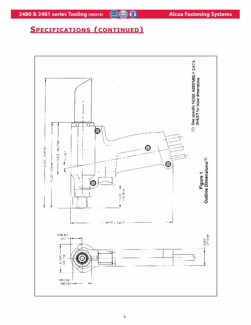
Model No. Length Width Height
2480 8.63 in. 1.88 in. 6.50 in.
21.9 cm 4.8 cm 1.65 cm
Note: Length and weight does not include hose/cord or nose assembly.
SSPECIFICATIONSPECIFICATIONS ( (ALLALL MODELSMODELS))POWER SOURCE:Huck POWERIG Hydraulic Unit
HOSE KITS:Use only genuine HUCK Hose Kits rated @ 10,000psi working pressure.
HYDRAULIC FLUID:ATF meeting DEXRON III, DEXRON IV, MERCON,Allison C‐4 or equivalent specifications.Fire resistant hydraulic fluid may also be used,and is required to comply with OSHA regulation1926.302 paragraph (d): "the fluid used inhydraulic power tools shall be fire resistant fluidapproved under schedule 30 of the US Bureau ofMines, Department of Interior, and shall retain itsoperating characteristics at the most extremetemperatures to which it will be exposed."
MAX OPERATING TEMP:125°F (51.7°C)
MAX FLOW RATE:2 gpm (7.5 l/m)
MAX PULL PRESSURE:8400 psi (580 bar)
MAX RETURN PRESSURE:3200 psi (220 bar)
PULL CAPACITY:5380 lbs (24 kN) @ 8400 psi
STROKE:.875 inches (2.22 cm)
WEIGHT:2.2 lbs (1 kg)
2480 & 2481 series Tooling (HK970) Alcoa Fastening Systems
6
SSPECIFICATIONSPECIFICATIONS ( (CONTINUEDCONTINUED))
2480 & 2481 series Tooling (HK970) Alcoa Fastening Systems
7
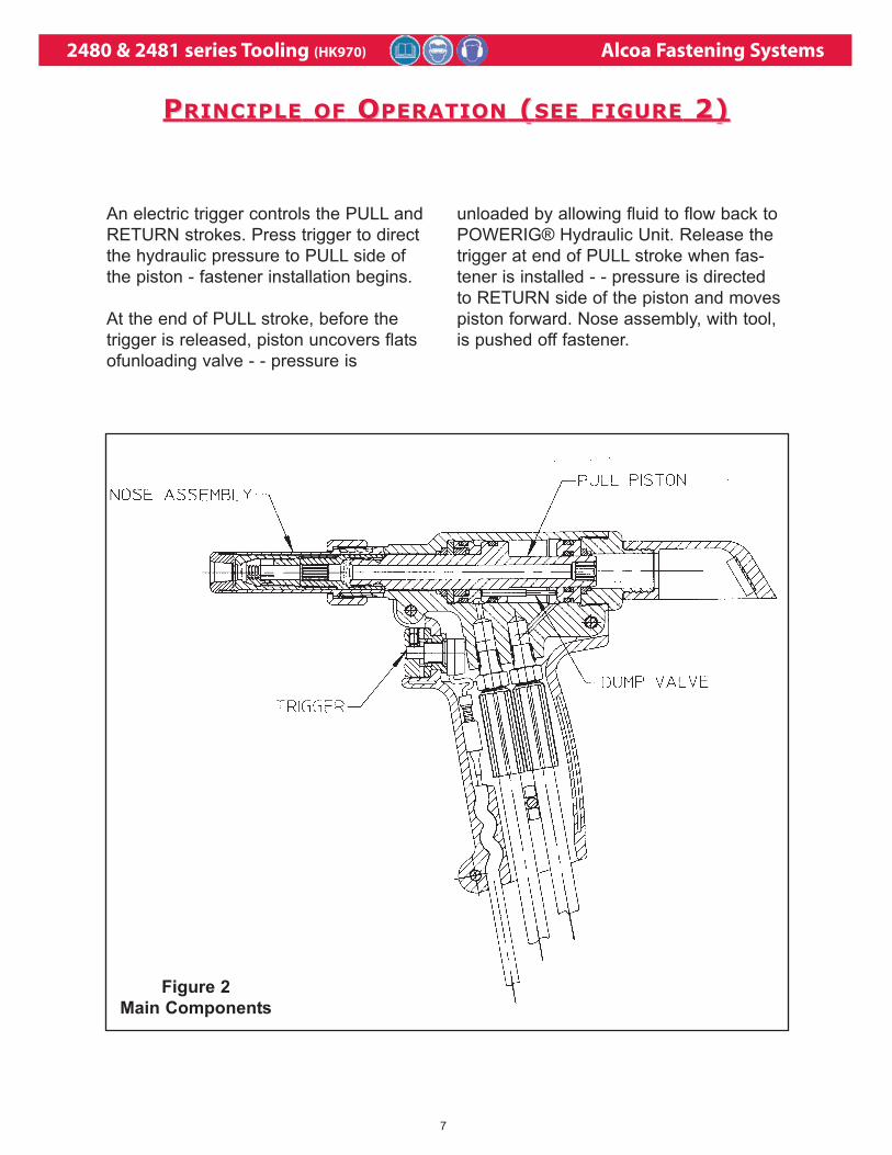
Figure 2
Main Components
An electric trigger controls the PULL and
RETURN strokes. Press trigger to direct
the hydraulic pressure to PULL side of
the piston - fastener installation begins.
At the end of PULL stroke, before the
trigger is released, piston uncovers flats
ofunloading valve - - pressure is
unloaded by allowing fluid to flow back to
POWERIG® Hydraulic Unit. Release the
trigger at end of PULL stroke when fas-
tener is installed - - pressure is directed
to RETURN side of the piston and moves
piston forward. Nose assembly, with tool,
is pushed off fastener.
PPRINCIPLERINCIPLE OFOF O OPERATIONPERATION ( (SEESEE FIGUREFIGURE 2) 2)
2480 & 2481 series Tooling (HK970) Alcoa Fastening Systems
8
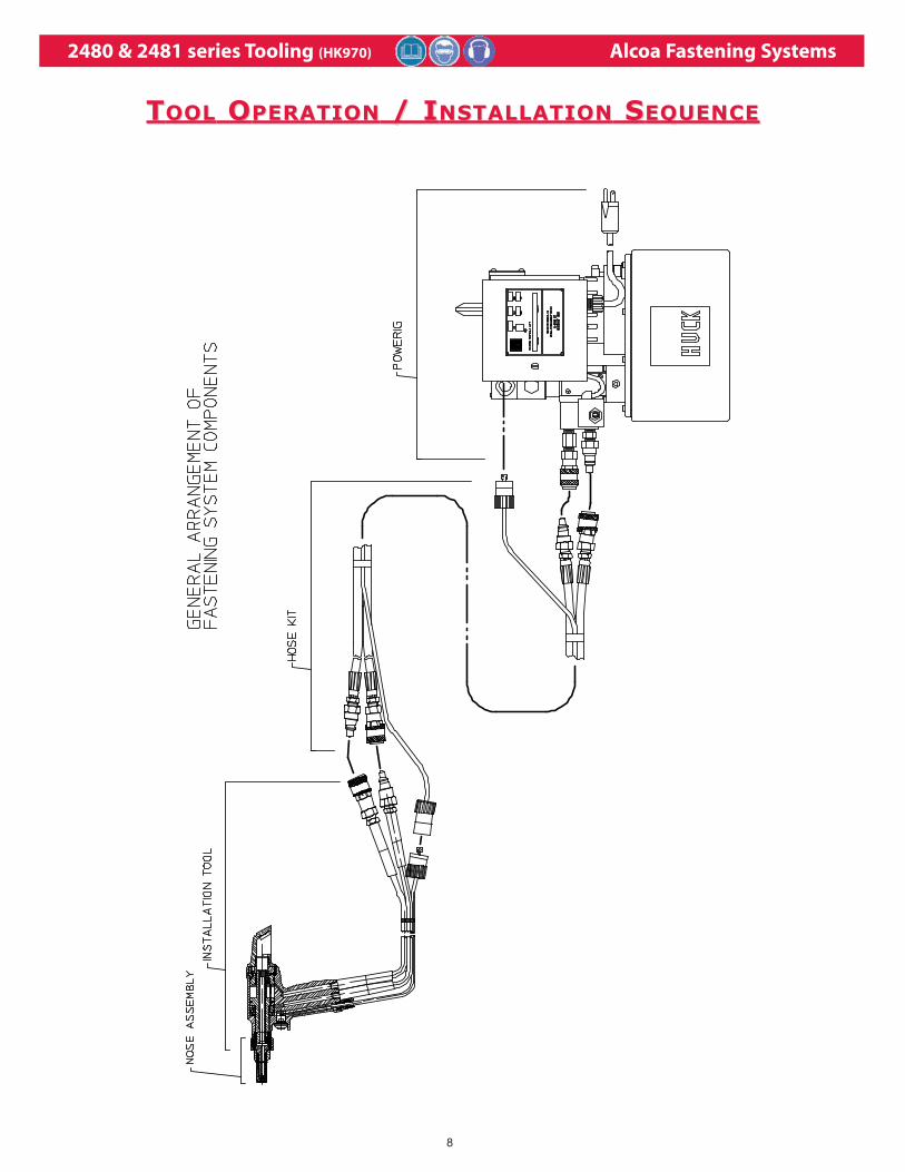
TTOOLOOL O OPERATIONPERATION / I / INSTALLATIONNSTALLATION S SEQUENCEEQUENCE
2480 & 2481 series Tooling (HK970) Alcoa Fastening Systems
9
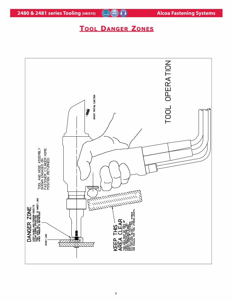
TTOOLOOL D DANGERANGER Z ZONESONES
2480 & 2481 series Tooling (HK970) Alcoa Fastening Systems
10
Note:
Where a part number (P/N) is given, Huck
sells that part.
Rub Slic-Tite TEFLON thread compound, or
equivalent, on pipe threads to prevent leaks
and for ease of assembly.
1. Use Huck POWERIG Hydraulic Unit, or
equivalent, that has been prepared for
operation per INSTRUCTION MANUAL. Check
both PULL and RETURN pressures, and if
required, adjust to pressures given in
SPECIFICATIONS of this manual. See both
hydraulic unit’s and T-124883’s Instruction
manuals before/during checking procedure.
Visually inspect for leaks and to verify that End
Cap is installed correctly.
2. First, turn hydraulic unit to OFF, and then,
disconnect power supply from hydraulic unit
— disconnect trigger control system from
hydraulic unit.
3. Connect tool hoses to hydraulic unit. If
required, adjust position of trigger assembly
on return pressure hose. Connect trigger
control system to hydraulic unit.
4. Connect hydraulic unit to power supply
(air or electric). Turn hydraulic unit to ON.
Hold Tool trigger depressed for 30 seconds;
depress trigger a few times to cycle tool and
to circulate hydraulic fluid — observe action
of Tool and check for leaks.
5. Select nose assembly from SELECTION
CHART for fastener to be installed. Disconnect
hydraulic unit from power supply; disconnect
Tool’s trigger control system from hydraulic
unit. Attach nose assembly to Tool per
instructions in NOSE ASSEMBLY DATA SHEET.
6. Reconnect Tool’s trigger control system to
hydraulic unit; reconnect unit to power
supply. Check operation of nose assembly —
see NOSE ASSEMBLY DATA SHEET. Install
fasteners in test plate of correct thickness
with proper size holes — inspect installed
fasteners. If fasteners do not pass inspection,
see TROUBLESHOOTING CHART to locate
and correct Tool’s malfunction.
7. Operator should receive training on proper use
from qualified personnel.
PPREPARATIONREPARATION FORFOR U USESE
WARNING: Correct PULL and RETURNpressures are required for operator’ssafety and for Installation TooI’s function.Gauge Set-Up T-124883CE is available forchecking pressures. See Tool’s SPECIFI-CATIONS and Gauge Instruction Manual.Failure to verify pressures may result insevere personal injury.
WARNING: Be sure to connect Tool’shydraulic hoses to POWERIG HydraulicUnit before connecting Tool’s switch con-trol cord to unit. If not connected in thisorder, severe personal Injury may occur.
CAUTION: Do not let disconnected hoses
and couplers contact a dirty floor. Keep
harmful material out of hydraulic fluid. Dirt
in hydraulic fluid causes valve failure In
Tool and In POWERIG Hydraulic Unit.
CAUTION: Do not use TEFLON®* tape on
pipe threads. Pipe threads may cause tape
to shred resulting in tool malfunction.
(Slic-Tite is available in stick form as Huck
P/N 503237.)
* Slic-Tite is a registered trademark of LA-CO Industries, Inc.* TEFLON is a registered trademark of DuPont Corp.
2480 & 2481 series Tooling (HK970) Alcoa Fastening Systems
11
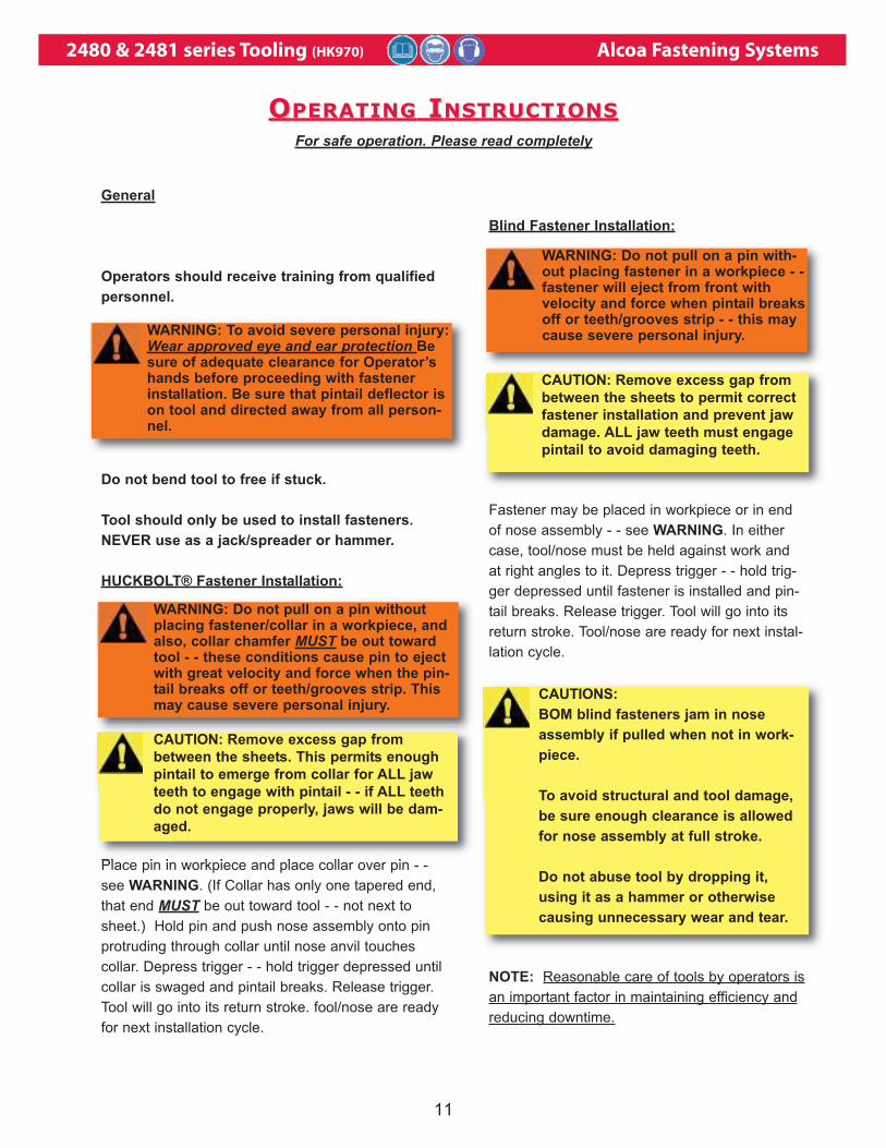
For safe operation. Please read completely
Blind Fastener Installation:
Fastener may be placed in workpiece or in end
of nose assembly - - see WARNING. In either
case, tool/nose must be held against work and
at right angles to it. Depress trigger - - hold trig-
ger depressed until fastener is installed and pin-
tail breaks. Release trigger. Tool will go into its
return stroke. Tool/nose are ready for next instal-
lation cycle.
NOTE: Reasonable care of tools by operators is
an important factor in maintaining efficiency and
reducing downtime.
General
Operators should receive training from qualified
personnel.
Do not bend tool to free if stuck.
Tool should only be used to install fasteners.
NEVER use as a jack/spreader or hammer.
HUCKBOLT® Fastener Installation:
Place pin in workpiece and place collar over pin - -
see WARNING. (If Collar has only one tapered end,
that end MUST be out toward tool - - not next to
sheet.) Hold pin and push nose assembly onto pin
protruding through collar until nose anvil touches
collar. Depress trigger - - hold trigger depressed until
collar is swaged and pintail breaks. Release trigger.
Tool will go into its return stroke. fool/nose are ready
for next installation cycle.
OOPERATINGPERATING I INSTRUCTIONSNSTRUCTIONS
WARNING: Do not pull on a pin withoutplacing fastener/collar in a workpiece, andalso, collar chamfer MUST be out towardtool - - these conditions cause pin to ejectwith great velocity and force when the pin-tail breaks off or teeth/grooves strip. Thismay cause severe personal injury.
CAUTION: Remove excess gap from
between the sheets. This permits enough
pintail to emerge from collar for ALL jaw
teeth to engage with pintail - - if ALL teeth
do not engage properly, jaws will be dam-
aged.
WARNING: To avoid severe personal injury:Wear approved eye and ear protection Besure of adequate clearance for Operator’shands before proceeding with fastenerinstallation. Be sure that pintail deflector ison tool and directed away from all person-nel.
WARNING: Do not pull on a pin with-out placing fastener in a workpiece - -fastener will eject from front withvelocity and force when pintail breaksoff or teeth/grooves strip - - this maycause severe personal injury.
CAUTION: Remove excess gap from
between the sheets to permit correct
fastener installation and prevent jaw
damage. ALL jaw teeth must engage
pintail to avoid damaging teeth.
CAUTIONS:
BOM blind fasteners jam in nose
assembly if pulled when not in work-
piece.
To avoid structural and tooI damage,
be sure enough clearance is allowed
for nose assembly at full stroke.
Do not abuse tool by dropping it,
using it as a hammer or otherwise
causing unnecessary wear and tear.
2480 & 2481 series Tooling (HK970) Alcoa Fastening Systems
12
CAUTION:
- Keep dirt and other material out of hydraulic sys-tem.
- Separated parts most be kept away from dirtywork surfaces.
- Dirt/debris in hydraulic fluid causes unloadingvalve failure in Tool and in POWERIG® HydraulicUnit’s valves.
- Always check tool assembly drawing for the properdirection of the flats on the Dump or UnloadingValve.
- Insure tool has been properly assembled prior touse.
Good Service PracticesThe efficiency and life of your Installation Tool
depends upon proper maintenance and good service
practices. Using our manual will help give you a clear
understanding of your tool and basic maintenance
procedures — please read entire page before pro-
ceeding with maintenance/repair.
Use proper hand tools in a clean well-lighted area for-
maintenance/repair — always be careful to keep
dirt/debris out of pneumatic and hydraulic systems.
Only standard hand tools are required in most cases;
where a special tool Is required, the description and
part number are given.
While clamping Installation Tool and/or parts in a vise,
and when parts require force, use suitable soft materi-
als to cushion impact — for example, using a half-
inch brass drift, wood block and/or vise with soft jaws
greatly diminishes the possibility of a damaged tool.
Remove components in a straight line without bend-
ing, cocking or undue force — reassemble tool with
the same care.
Note: Individual parts must be handled carefully and
examined for damage or wear —replace parts where
required. Always replace O-rings and back-up rings
when the tool Is disassembled for any reason — see
SERVICE PARTS KIT.
Note: Consult manual’s TROUBLESHOOTING
CHART if malfunction occurs — then see appropriate
section of DISASSEMBLY, ASSEMBLY and SEC-
TIONAL VIEW W/TOOL P/N’s.
Note: Where a part number (P/N) is given, Huck sells
that part.
Fluid MaintenanceFor fluid maintenance please refer to NAS 1638 class
9 or ISO CODE 18/15 or SAE level 6
Standard Sealants, Lubricants and SERV-ICE PARTS KITRub SLIC-TITE TEFLON thread compound, or equiv-
alent, on pipe threads to prevent leaks and for ease
of assembly — CAUTION: Do not use TEFLONtape on pipe threads — particles of shredded tape
cause hydraulic unit valve failure/malfunction. (SLIC-
TITE —In stick form, P/N 503237.)
Smear LUBRIPLATE 130AA, or equivalent lubricant,
on O-rings and mating surfaces this prevents nick-
ing/pinching O-rings on any rough/tight spot and
increases ease of assembly. (LUBRIPLATE 130AA —
in tube, P/N 502723.)
SERVICE PARTS KIT contains perishable parts for
your specific Tool — see NOTES FOR TOOL. For
conve ience and as experience indicates, keep extra
Kits (O-rings; back-up rings: other standard items)
and Tool parts on hand. As an alternative, you can
obtain O- rings and back-up rings from any regular
retailer of these items — ask for: O-ring size (AS
568-number): material and durometer. For additional
information/specifications on O-rings and back-up
rings, see NOTES AND SPECIFICATlONS FOR
STANDARD PARTS.
Inspect tool daily. Check hoses, fittings and discon-
nects for leaks or damage.
MMAINTENANCEAINTENANCE
2480 & 2481 series Tooling (HK970) Alcoa Fastening Systems
13
PREVENTIVE MAINTENANCE
System InspectionOperating efficiency of the Tool is directlyrelated to performance of complete sys-tem, including tool/nose assembly,hydraulic hoses, control trigger assemblyand the POWERIG® Hydraulic UnitTherefore, an effective preventive main-tenance program includes scheduledinspections of the system to detect andcorrect minor troubles.
1. Inspect Tool for external damage.
2. Verify that hoses and fittings, and trig-ger connections are secure.
3. Inspect hydraulic hoses for signs ofdamage. Replace if required.
4. Inspect tool, hoses, and POWERIGHydraulic Unit during operation todetect abnormal heating, leaks orvibration.
POWERIG Hydraulic Unit MaintenanceMaintenance and repair instructions arein applicable POWERIG Hydraulic UnitInstruction Manual.
Tool/Nose Assembly Maintenance andPrecautionsWhenever disassembled, and also atregular intervals (depending on severityand length of use), replace all O-ringsand back-up rings. Spare Parts Kitsshould be kept on hand. Inspect cylinderbore, piston and rod/extension, andunloading valve for scored surfaces,excessive wear or damage — replaceparts as necessary. On any assemblywith UNITIZEDTM Jaws, clean all parts inmineral spirits or isopropyl alcohol only— under no circumstances let jaws comein contact with other solvents — also, donot let jaws soak; dry the jaws immedi-ately after cleaning; dry other partsbefore assembling. Urethane soaks upother solvents, then swells up andbecomes unusable. Use a sharp pointed“pick” to remove imbedded particles fromthe pull grooves of the jaws. If additionalinformation is required, see appropriateNOSE ASSEMBLY DATA SHEET.
MMAINTENANCEAINTENANCE ( (CONTINUEDCONTINUED))
2480 & 2481 series Tooling (HK970) Alcoa Fastening Systems
14
I. Tool fails to operate when trigger is depressed. a. Inoperative POWERIG® Hydraulic Unit. See applicable
instruction manual.
b. Loose air or electric connections.
c. Damaged trigger assembly
d. Loose or faulty hydraulic hose couplings
e. Unloading valve not installed in Tool.
2. Tool operates in reverse. connections a. Reversed hydraulic hose between hydraulic unit and Tool.
3. Tool leaks hydraulic fluid. a. Defective Tool 0-rings or loose hose connections at Tool.
4. Hydraulic couplers leak fluid. a. Damaged or worn 0-rings in coupler body — see Coupler,
110440.
5. Hydraulic fluid overheats. a. Hydraulic unit not operating properly — see manual.
b. Unloading valve installed incorrectly.
c. POWERIG Hydraulic Unit running in reverse (918; 918-5
only) — see unit’s manual.
6. Tool operates erratically and fails to install a. Low or erratic hydraulic pressure — air in system.
fastener properly.
b. Damaged or worn piston 0-ring in Tool.
c. Unloading valve installed incorrectly.
d. Excessive wear on sliding surfaces of Tool parts.
e. Excessive wear of unloading valve in Tool.
7. Pull grooves on fastener pintail stripped during a. Operator not sliding anvil completely onto fastener pintail.
PULL stroke.
b. Incorrect fastener grip.
c. Worn or damaged jaw segments.
d. Metal particles in pull grooves of jaw segments.
e. Excessive sheet gap.
8. Collar of HUCKBOLT® fastener not completely a. Improper Tool operation — see Trouble 6.
swaged. b. Scored anvil.
9. Shear collar on Huck blind fastener not driven. a. Improper Tool operation.
b. Worn or damaged driving anvil in nose assembly.
10. Tool ”hangs-up” on swaged collar of HUCKBOLT a. Improper Tool operation — see Trouble 6.
Fastener. b. RETURN pressure too low.
c. Nose assembly not installed per NOSE DATA SHEET.
11. Pintail of fastener fails to break. a. Improper Tool operation — see Trouble 6.
b. Pull grooves on fastener stripped. — see Trouble 7.
c. PULL pressure too low.
d. Worn unloading valve.
Always check the simplest possible cause of a malfunction first. For example, a loose or disconnected trigger
line. Then proceed logically, eliminating each possible cause until the defective part is located. Where possible,
substitute known good parts for suspected defective parts. Use Trouble Shooting Chart as an aid for locating
and correcting trouble.
TTROUBLESHOOTINGROUBLESHOOTING
2480 & 2481 series Tooling (HK970) Alcoa Fastening Systems
15
The quantity of spare parts that should be kept on hand varies with the application and
number of tools in service. Spare service kits, 2480KIT, containing perishable parts such
as seals, back-up rings, etc. should be kept on hand at all times - - see below. This kit is
for all tools.
Service Kit, 2480KIT
Part No. Description Quan.
505843 WIPER 1
507108 WIPER 1
505818 POLY-SEAL 1
505849 O-RING 1
500773 O-RING 1
500777 O-RING 1
500816 O-RING 2
500810 O-RING 1
504438 O-RING 1
501102 BACK-UP RING 1
501104 BACK-UP RING 1
501110 BACK-UP RING 3
8-2480 2480 H.I.T. ASSEMBLY DWG. 1
8-A2480 A2480 H.I.T. ASSEMBLY DWG. 1
Specifications for Standard Parts
1. All part numbers shown in this manual are available from Huck.
2480B Pintail Bottle Assembly
Also available is part no. 128017 Pintail Bottle Assembly to convert tool to 2480B
(Refer to fig 3-3g for optional assembly tool kits and notes)
SSPAREPARE P PARTSARTS S SERVICEERVICE K KITIT
SSTICKERTICKER L LOCATIONSOCATIONS
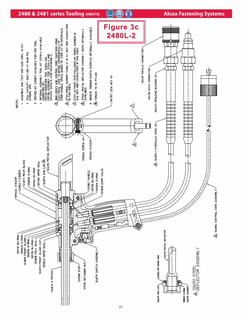
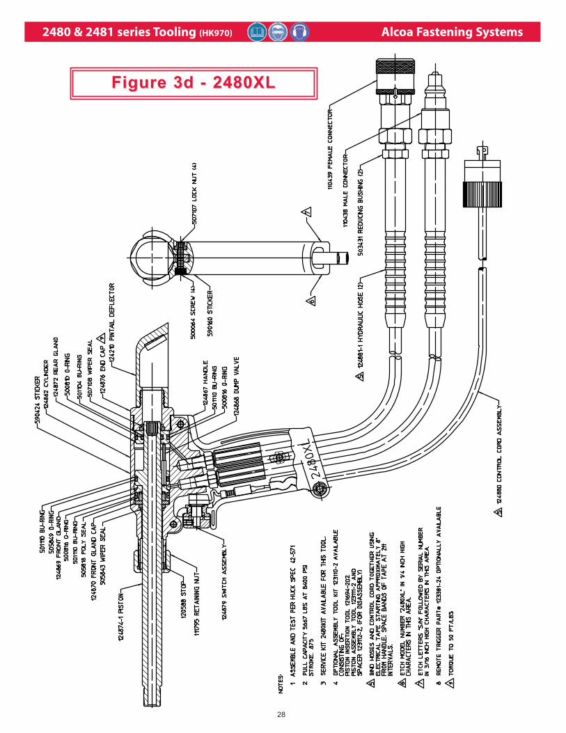
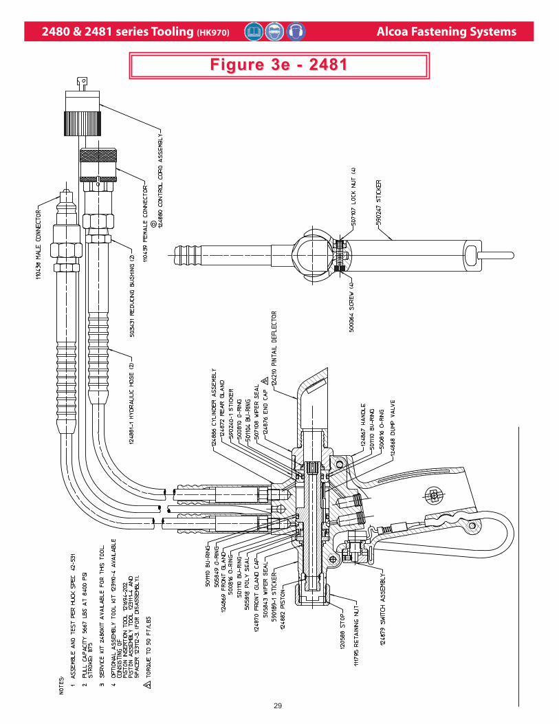
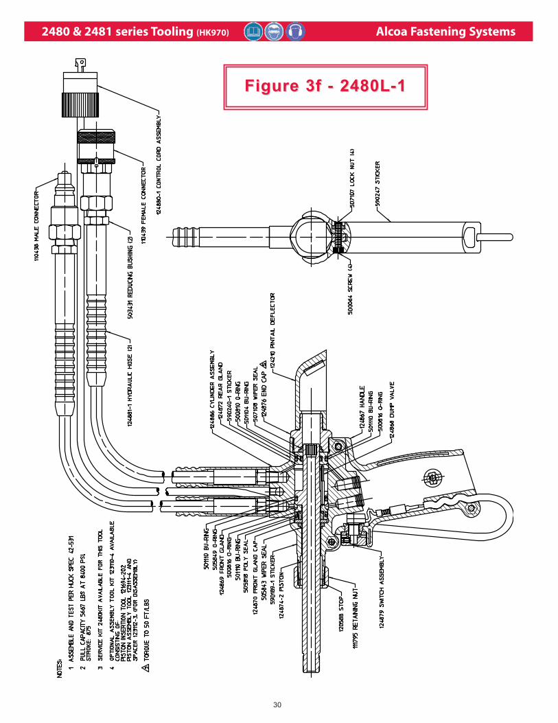
The 2480 and 2481 series tools come labeled with Sticker part number 590424,
which contains safety and pressure settings information. It is necessary that this sticker
remain on the tool and is easily read. If sticker becomes damaged or worn, or if it have
been removed from the tool, or when replacing Cylinder, this sticker must be
ordered and placed in the location shown. Sticker locations and part numbers may
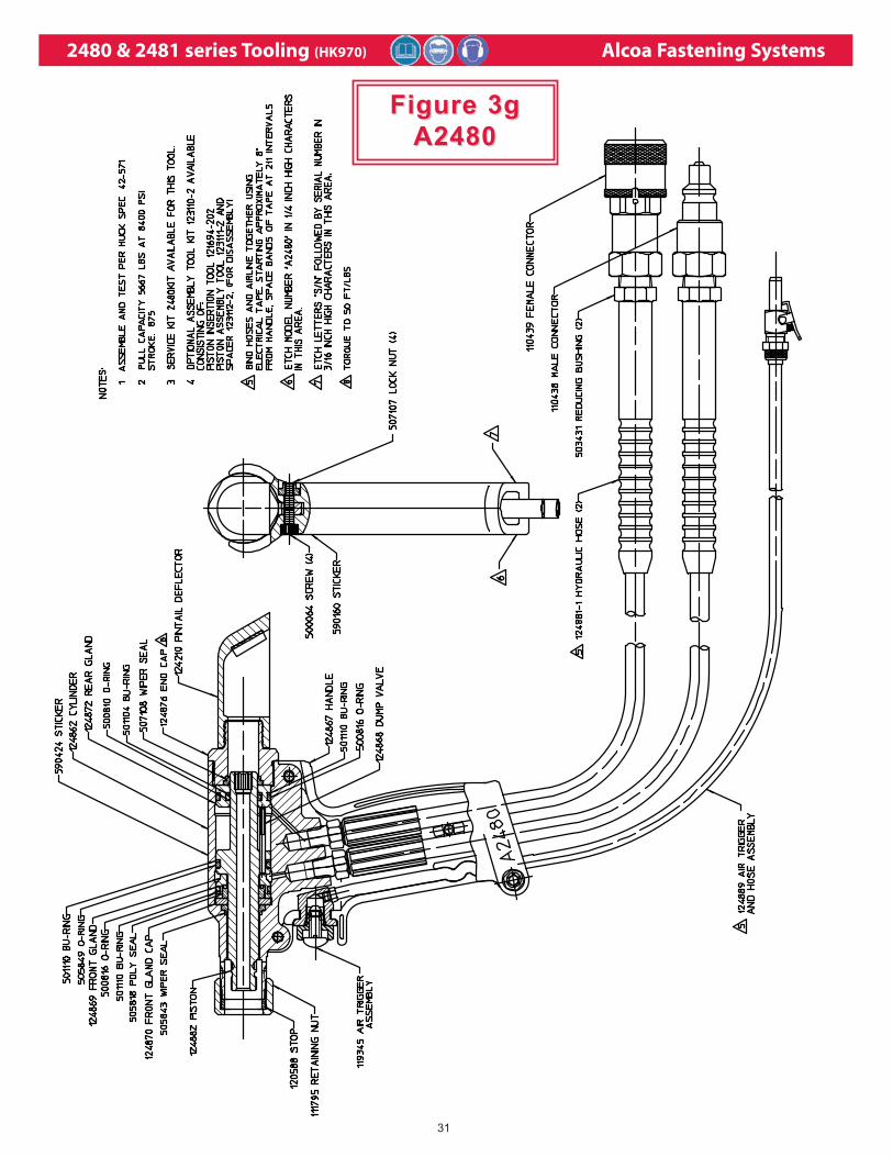
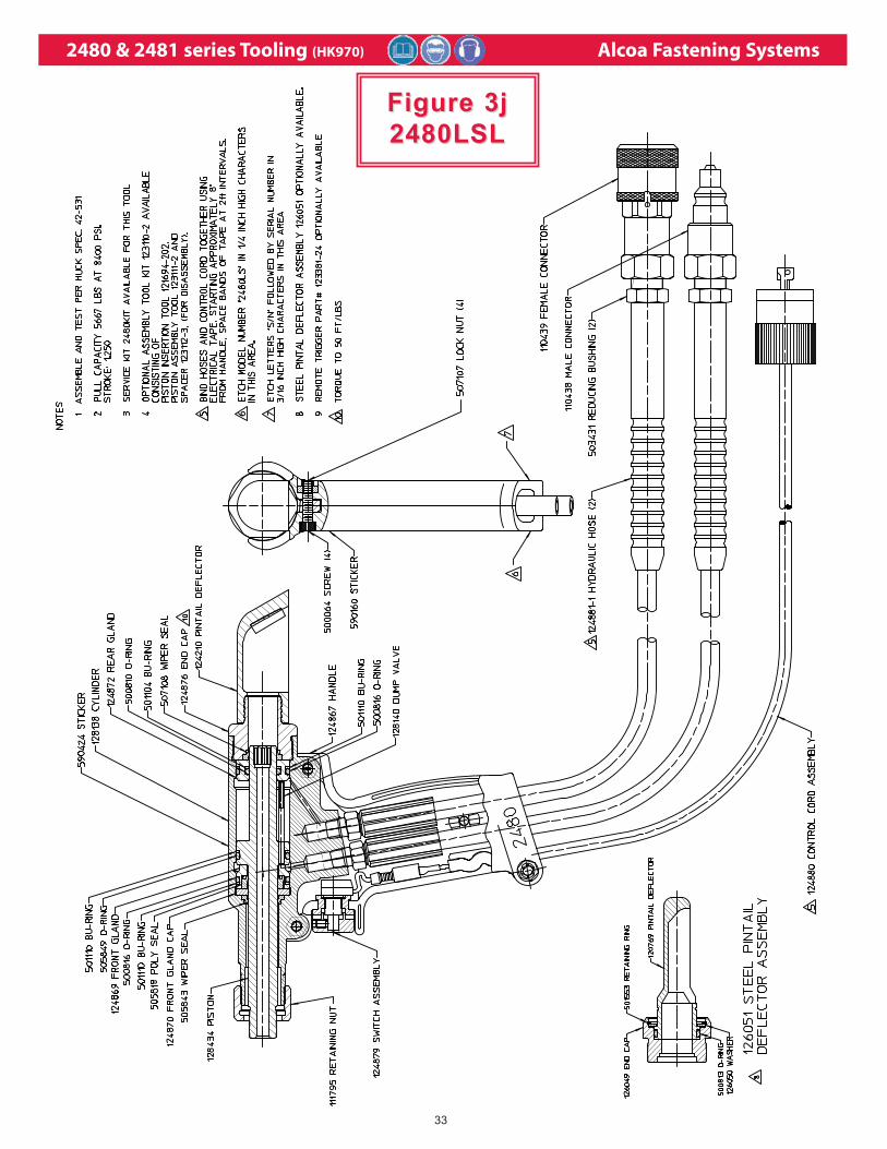
be found in Figure3 through 3j.
2480 & 2481 series Tooling (HK970) Alcoa Fastening Systems
16
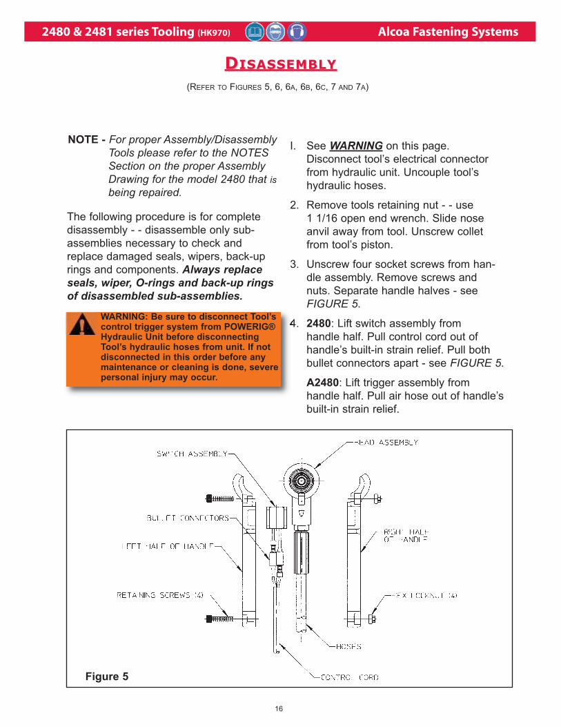
The following procedure is for complete
disassembly - - disassemble only sub-
assemblies necessary to check and
replace damaged seals, wipers, back-up
rings and components. Always replaceseals, wiper, O-rings and back-up ringsof disassembled sub-assemblies.
I. See WARNING on this page.
Disconnect tool’s electrical connector
from hydraulic unit. Uncouple tool’s
hydraulic hoses.
2. Remove tools retaining nut - - use
1 1/16 open end wrench. Slide nose
anvil away from tool. Unscrew collet
from tool’s piston.
3. Unscrew four socket screws from han-
dle assembly. Remove screws and
nuts. Separate handle halves - see
FIGURE 5.
4. 2480: Lift switch assembly from
handle half. Pull control cord out of
handle’s built-in strain relief. Pull both
bullet connectors apart - see FIGURE 5.
A2480: Lift trigger assembly from
handle half. Pull air hose out of handle’s
built-in strain relief.
(REFER TO FIGURES 5, 6, 6A, 6B, 6C, 7 AND 7A)
Figure 5
NOTE - For proper Assembly/DisassemblyTools please refer to the NOTESSection on the proper AssemblyDrawing for the model 2480 that isbeing repaired.
DDISASSEMBLYISASSEMBLY
WARNING: Be sure to disconnect Tool’scontrol trigger system from POWERIG®Hydraulic Unit before disconnectingTool’s hydraulic hoses from unit. If notdisconnected in this order before anymaintenance or cleaning is done, severepersonal injury may occur.
2480 & 2481 series Tooling (HK970) Alcoa Fastening Systems
17
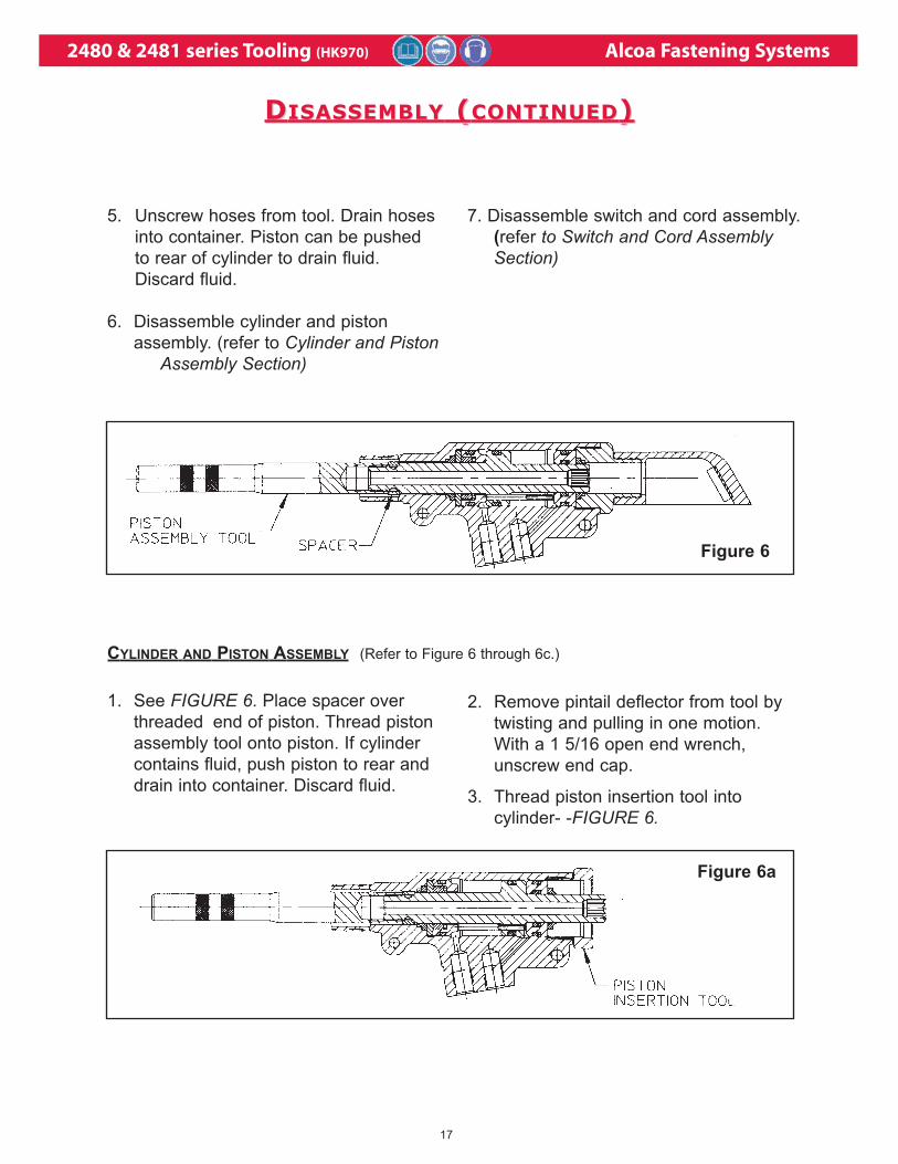
5. Unscrew hoses from tool. Drain hoses
into container. Piston can be pushed
to rear of cylinder to drain fluid.
Discard fluid.
6. Disassemble cylinder and piston
assembly. (refer to Cylinder and PistonAssembly Section)
7. Disassemble switch and cord assembly.
(refer to Switch and Cord Assembly Section)
1. See FIGURE 6. Place spacer over
threaded end of piston. Thread piston
assembly tool onto piston. If cylinder
contains fluid, push piston to rear and
drain into container. Discard fluid.
2. Remove pintail deflector from tool by
twisting and pulling in one motion.
With a 1 5/16 open end wrench,
unscrew end cap.
3. Thread piston insertion tool into
cylinder- -FIGURE 6.
CYLINDER AND PISTON ASSEMBLY (Refer to Figure 6 through 6c.)
Figure 6
Figure 6a
DDISASSEMBLYISASSEMBLY ( (CONTINUEDCONTINUED))
2480 & 2481 series Tooling (HK970) Alcoa Fastening Systems
18
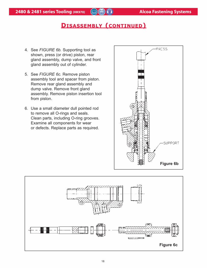
4. See FIGURE 6b. Supporting tool as
shown, press (or drive) piston, rear
gland assembly, dump valve, and front
gland assembly out of cylinder.
5. See FIGURE 6c. Remove piston
assembly tool and spacer from piston.
Remove rear gland assembly and
dump valve. Remove front gland
assembly. Remove piston insertion tool
from piston.
6. Use a small diameter dull pointed rod
to remove all O-rings and seals.
Clean parts, including O-ring grooves.
Examine all components for wear
or defects. Replace parts as required.
Figure 6b
Figure 6c
DDISASSEMBLYISASSEMBLY ( (CONTINUEDCONTINUED))
2480 & 2481 series Tooling (HK970) Alcoa Fastening Systems
19
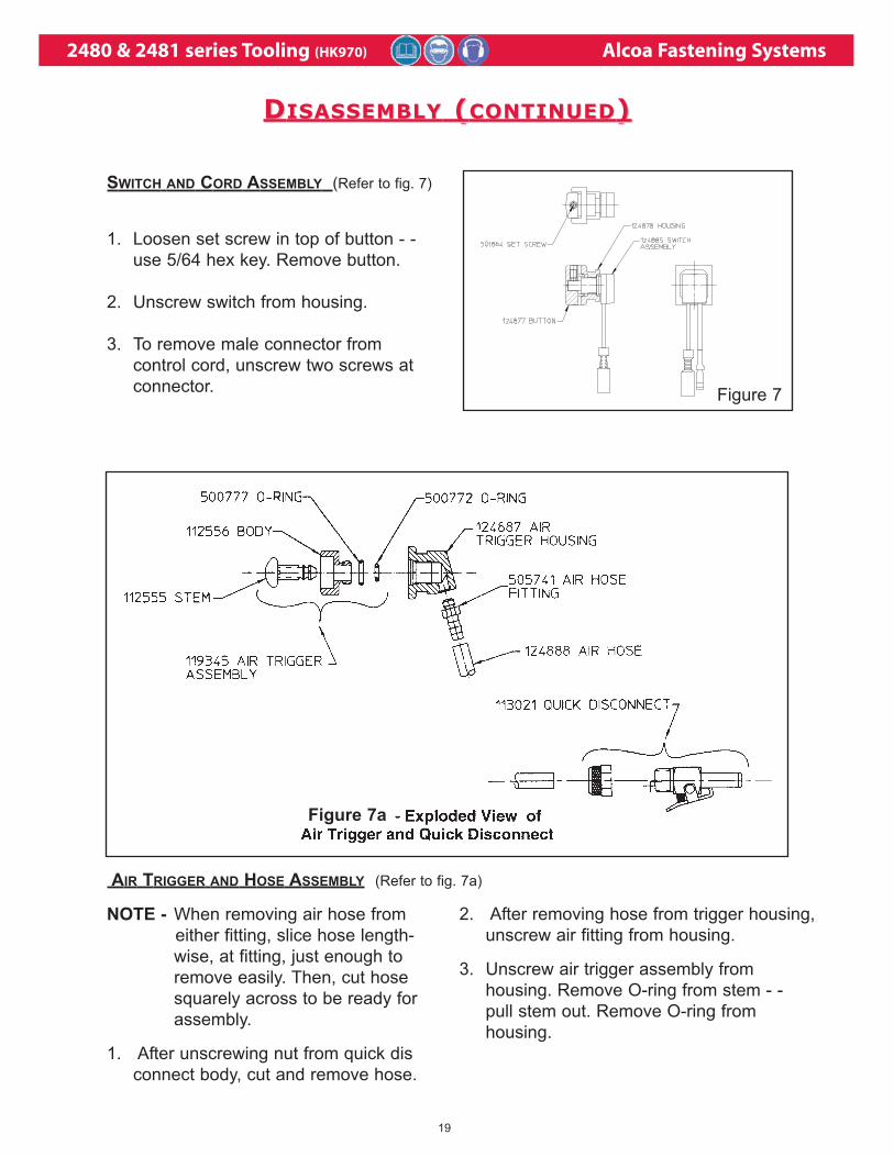
1. Loosen set screw in top of button - -
use 5/64 hex key. Remove button.
2. Unscrew switch from housing.
3. To remove male connector from
control cord, unscrew two screws at
connector.
NOTE - When removing air hose from
either fitting, slice hose length-
wise, at fitting, just enough to
remove easily. Then, cut hose
squarely across to be ready for
assembly.
1. After unscrewing nut from quick dis
connect body, cut and remove hose.
2. After removing hose from trigger housing,
unscrew air fitting from housing.
3. Unscrew air trigger assembly from
housing. Remove O-ring from stem - -
pull stem out. Remove O-ring from
housing.
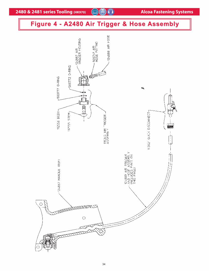
AIR TRIGGER AND HOSE ASSEMBLY (Refer to fig. 7a)
Figure 7a
SWITCH AND CORD ASSEMBLY (Refer to fig. 7)
Figure 7
DDISASSEMBLYISASSEMBLY ( (CONTINUEDCONTINUED))
2480 & 2481 series Tooling (HK970) Alcoa Fastening Systems
20
Refer to Figures 8, 8a, 8b, 8c, 8d, 9, 10 and 11 and
MAINTENANCE: General Precautions - - clean out
O-ring grooves and reinstall perishable parts
(seals, etc.) - - see below. Use service kit,2480KIT.
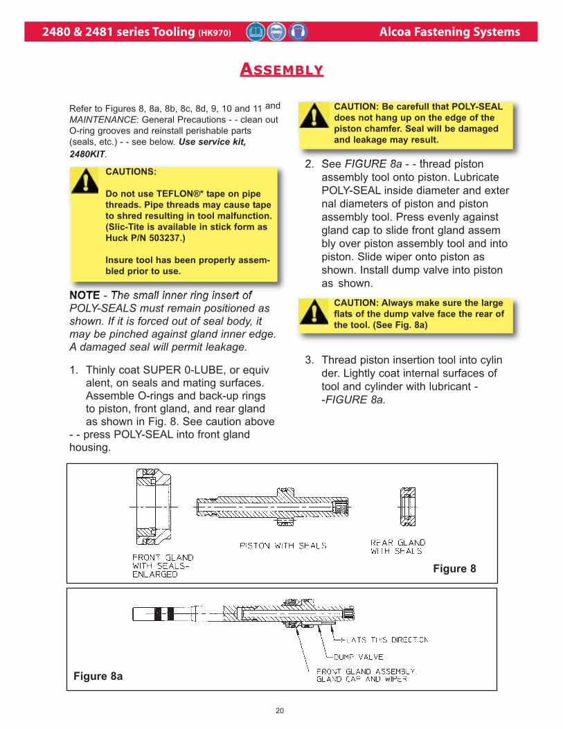
NOTE - The small inner ring insert ofPOLY-SEALS must remain positioned asshown. If it is forced out of seal body, itmay be pinched against gland inner edge.A damaged seal will permit leakage.
1. Thinly coat SUPER 0-LUBE, or equivalent, on seals and mating surfaces.Assemble O-rings and back-up rings to piston, front gland, and rear glandas shown in Fig. 8. See caution above
- - press POLY-SEAL into front gland housing.
Figure 8
2. See FIGURE 8a - - thread piston
assembly tool onto piston. Lubricate
POLY-SEAL inside diameter and exter
nal diameters of piston and piston
assembly tool. Press evenly against
gland cap to slide front gland assem
bly over piston assembly tool and into
piston. Slide wiper onto piston as
shown. Install dump valve into piston
as shown.
3. Thread piston insertion tool into cylin
der. Lightly coat internal surfaces of
tool and cylinder with lubricant -
-FIGURE 8a.
Figure 8a
AASSEMBLYSSEMBLY
CAUTIONS:
Do not use TEFLON®* tape on pipe
threads. Pipe threads may cause tape
to shred resulting in tool malfunction.
(Slic-Tite is available in stick form as
Huck P/N 503237.)
Insure tool has been properly assem-
bled prior to use.
CAUTION: Always make sure the large
flats of the dump valve face the rear of
the tool. (See Fig. 8a)
CAUTION: Be carefull that POLY-SEAL
does not hang up on the edge of the
piston chamfer. Seal will be damaged
and leakage may result.
2480 & 2481 series Tooling (HK970) Alcoa Fastening Systems
21
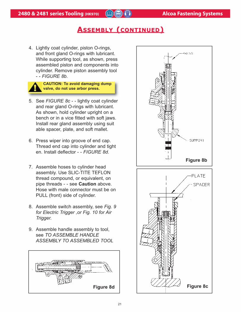
4. Lightly coat cylinder, piston O-rings,
and front gland O-rings with lubricant.
While supporting tool, as shown, press
assembled piston and components into
cylinder. Remove piston assembly tool
- - FIGURE 8b.
Figure 8b
5. See FIGURE 8c - - lightly coat cylinder
and rear gland O-rings with lubricant.
As shown, hold cylinder upright on a
bench or in a vice fitted with soft jaws.
Install rear gland assembly using suit
able spacer, plate, and soft mallet.
6. Press wiper into groove of end cap.
Thread end cap into cylinder and tight
en. Install deflector - - FIGURE 8d.
Figure 8d
7. Assemble hoses to cylinder head
assembly. Use SLIC-TITE TEFLON
thread compound, or equivalent, on
pipe threads - - see Caution above.
Hose with male connector must be on
PULL (front) side of cylinder.
8. Assemble switch assembly, see Fig. 9 for Electric Trigger ,or Fig. 10 for Air Trigger.
9. Assemble handle assembly to tool,
see TO ASSEMBLE HANDLEASSEMBLY TO ASSEMBLED TOOL
Figure 8c
AASSEMBLYSSEMBLY ( (CONTINUEDCONTINUED))
CAUTION: To avoid damaging dump
valve, do not use arbor press.
2480 & 2481 series Tooling (HK970) Alcoa Fastening Systems
22
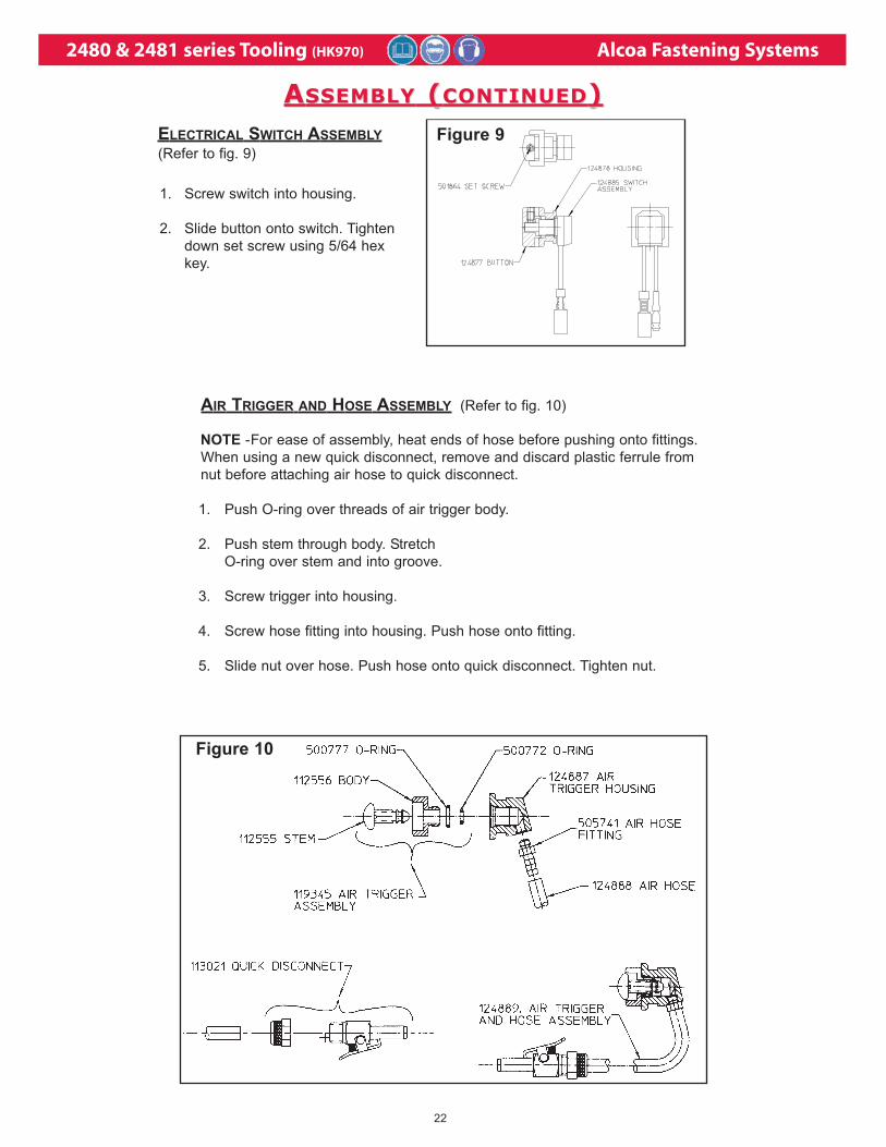
AIR TRIGGER AND HOSE ASSEMBLY (Refer to fig. 10)
NOTE -For ease of assembly, heat ends of hose before pushing onto fittings.
When using a new quick disconnect, remove and discard plastic ferrule from
nut before attaching air hose to quick disconnect.
1. Push O-ring over threads of air trigger body.
2. Push stem through body. Stretch
O-ring over stem and into groove.
3. Screw trigger into housing.
4. Screw hose fitting into housing. Push hose onto fitting.
5. Slide nut over hose. Push hose onto quick disconnect. Tighten nut.
Figure 10
1. Screw switch into housing.
2. Slide button onto switch. Tighten
down set screw using 5/64 hex
key.
ELECTRICAL SWITCH ASSEMBLY
(Refer to fig. 9)
Figure 9
AASSEMBLYSSEMBLY ( (CONTINUEDCONTINUED))
2480 & 2481 series Tooling (HK970) Alcoa Fastening Systems
23
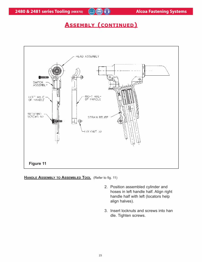
HANDLE ASSEMBLY TO ASSEMBLED TOOL (Refer to fig. 11)
Figure 11
2. Position assembled cylinder and
hoses in left handle half. Align right
handle half with left (locators help
align halves).
3. Insert locknuts and screws into han
dle. Tighten screws.
AASSEMBLYSSEMBLY ( (CONTINUEDCONTINUED))
2480 & 2481 series Tooling (HK970) Alcoa Fastening Systems
24
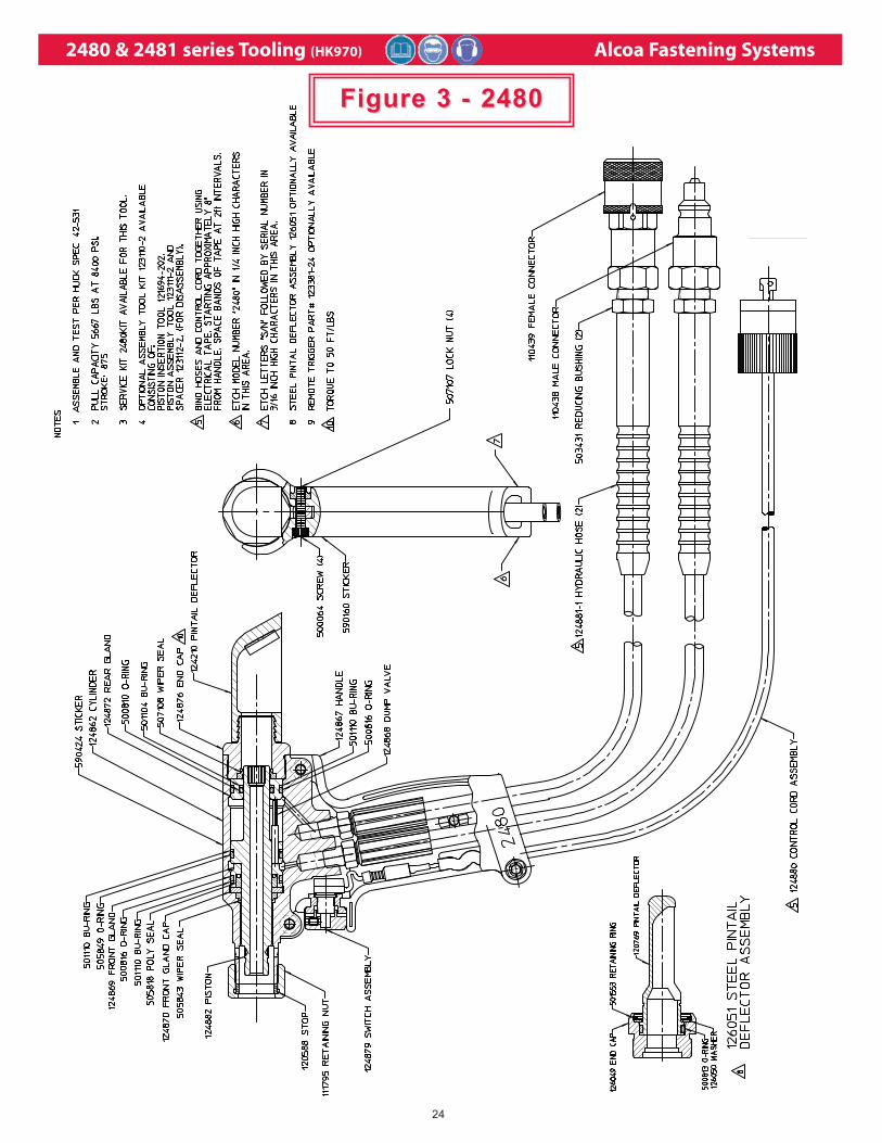
Figure 3 - 2480Figure 3 - 2480
2480 & 2481 series Tooling (HK970) Alcoa Fastening Systems
25
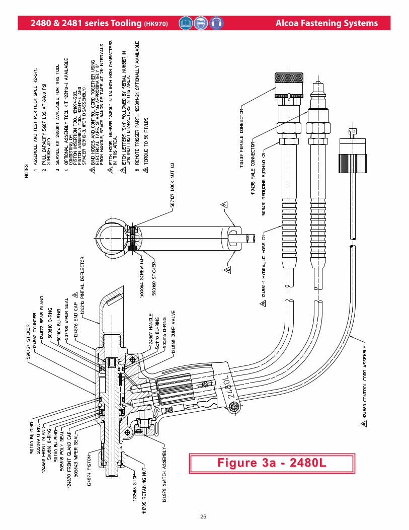
Figure 3a - 2480LFigure 3a - 2480L
2480 & 2481 series Tooling (HK970) Alcoa Fastening Systems
26
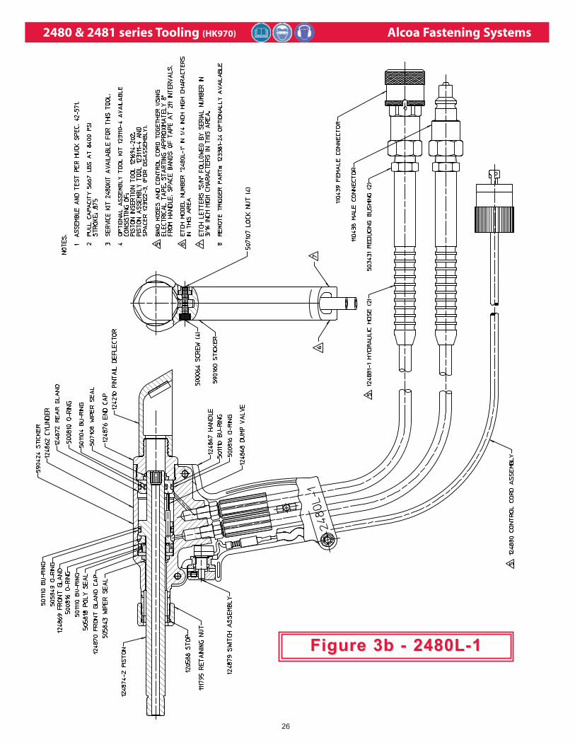
Figure 3b - 2480L-1Figure 3b - 2480L-1
2480 & 2481 series Tooling (HK970) Alcoa Fastening Systems
27
Figure 3cFigure 3c
2480L-22480L-2
2480 & 2481 series Tooling (HK970) Alcoa Fastening Systems
28
Figure 3d - 2480XLFigure 3d - 2480XL
2480 & 2481 series Tooling (HK970) Alcoa Fastening Systems
29
Figure 3e - 2481Figure 3e - 2481
2480 & 2481 series Tooling (HK970) Alcoa Fastening Systems
30
Figure 3f - 2480L-1Figure 3f - 2480L-1
2480 & 2481 series Tooling (HK970) Alcoa Fastening Systems
31
Figure 3gFigure 3g
A2480A2480

2480 & 2481 series Tooling (HK970) Alcoa Fastening Systems
32
Figure 3hFigure 3h
2480LS2480LS
2480 & 2481 series Tooling (HK970) Alcoa Fastening Systems
33
Figure 3jFigure 3j
2480LSL2480LSL
2480 & 2481 series Tooling (HK970) Alcoa Fastening Systems
34
Figure 4 - A2480 Air Trigger & Hose AssemblyFigure 4 - A2480 Air Trigger & Hose Assembly
2480 & 2481 series Tooling (HK970) Alcoa Fastening Systems
35
LLIMITEDIMITED W WARRANTIESARRANTIES
TOOLING WARRANTY:Huck warrants that tooling and other items (excluding
fasteners, and hereinafter referred as "other items")
manufactured by Huck shall be free from defects in
workmanship and materials for a period of ninety (90)
days from the date of original purchase.
WARRANTY ON "NON STANDARD OR CUSTOM
MANUFACTURED PRODUCTS":With regard to non-standard products or custom man-
ufactured products to customer's specifications, Huck
warrants for a period of ninety (90) days from the date
of purchase that such products shall meet Buyer's
specifications, be free of defects in workmanship and
materials. Such warranty shall not be effective with
respect to non-standard or custom products manufac-
tured using buyer-supplied molds, material, tooling
and fixtures that are not in good condition or repair
and suitable for their intended purpose.
THERE ARE NO WARRANTIES WHICH EXTEND
BEYOND THE DESCRIPTION ON THE FACE
HEREOF. HUCK MAKES NO OTHER WAR-
RANTIES AND EXPRESSLY DISCLAIMS ANY
OTHER WARRANTIES, INCLUDING IMPLIED
WARRANTIES AS TO MERCHANTABILITY OR AS
TO THE FITNESS OF THE TOOLING, OTHER
ITEMS, NONSTANDARD OR CUSTOM MANUFAC-
TURED PRODUCTS FOR ANY PARTICULAR PUR-
POSE AND HUCK SHALL NOT BE LIABLE FOR
ANY LOSS OR DAMAGE, DIRECTLY OR INDI-
RECTLY, ARISING FROM THE USE OF SUCH
TOOLING, OTHER ITEMS, NONSTANDARD OR
CUSTOM MANUFACTURED PRODUCTS OR
BREACH OF WARRANTY OR FOR ANY CLAIM
FOR INCIDENTAL OR CONSEQUENTIAL DAM-
AGES.
Huck's sole liability and Buyer's exclusive remedy for
any breach of warranty shall be limited, at Huck's
option, to replacement or repair, at FOB Huck's plant,
of Huck manufactured tooling, other items, nonstan-
dard or custom products found to be defective in
specifications, workmanship and materials not other-
wise the direct or indirect cause of Buyer supplied
molds, material, tooling or fixtures. Buyer shall give
Huck written notice of claims for defects within the
ninety (90) day warranty period for tooling, other
items, nonstandard or custom products described
above and Huck shall inspect products for which such
claim is made.
TOOLING, PART(S) AND OTHER ITEMS NOT MANU-
FACTURED BY HUCK:HUCK MAKES NO WARRANTY WITH RESPECT
TO THE TOOLING, PART(S) OR OTHER ITEMS
MANUFACTURED BY THIRD PARTIES. HUCK
EXPRESSLY DISCLAIMS ANY WARRANTY
EXPRESSED OR IMPLIED, AS TO THE CONDI-
TION, DESIGN, OPERATION, MERCHANTABILITY
OR FITNESS FOR USE OF ANY TOOL, PART(S),
OR OTHER ITEMS THEREOF NOT MANUFAC-
TURED BY HUCK. HUCK SHALL NOT BE LIABLE
FOR ANY LOSS OR DAMAGE, DIRECTLY OR INDI-
RECTLY, ARISING FROM THE USE OF SUCH
TOOLING, PART(S) OR OTHER ITEMS OR
BREACH OF WARRANTY OR FOR ANY CLAIM
FOR INCIDENTAL OR CONSEQUENTIAL DAM-
AGES.
The only warranties made with respect to such tool,
part(s) or other items thereof are those made by the
manufacturer thereof and Huck agrees to cooperate
with Buyer in enforcing such warranties when such
action is necessary.
Huck shall not be liable for any loss or damage result-
ing from delays or nonfulfillment of orders owing to
strikes, fires, accidents, transportation companies or
for any reason or reasons beyond the control of the
Huck or its suppliers.
HUCK INSTALLATION EQUIPMENT:Huck International, Inc. reserves the right to make
changes in specifications and design and to discontin-
ue models without notice.
Huck Installation Equipment should be serviced by
trained service technicians only.
Always give the Serial Number of the equipment
when corresponding or ordering service parts.
Complete repair facilities are maintained by Huck
International, Inc. Please contact one of the offices
listed below.
Eastern
One Corporate Drive Kingston, New York 12401-0250
Telephone (845) 331-7300 FAX (845) 334-7333
Outside USA and Canada
Contact your nearest Huck International Office, see
back cover.
In addition to the above repair facilities, there are
Authorized Tool Service Centers (ATSC's) located
throughout the United States. These service centers
offer repair services, spare parts, Service Parts Kits,
Service Tools Kits and Nose Assemblies. Please con-
tact your Huck Representative or the nearest Huck
office listed on the back cover for the ATSC in your
area.
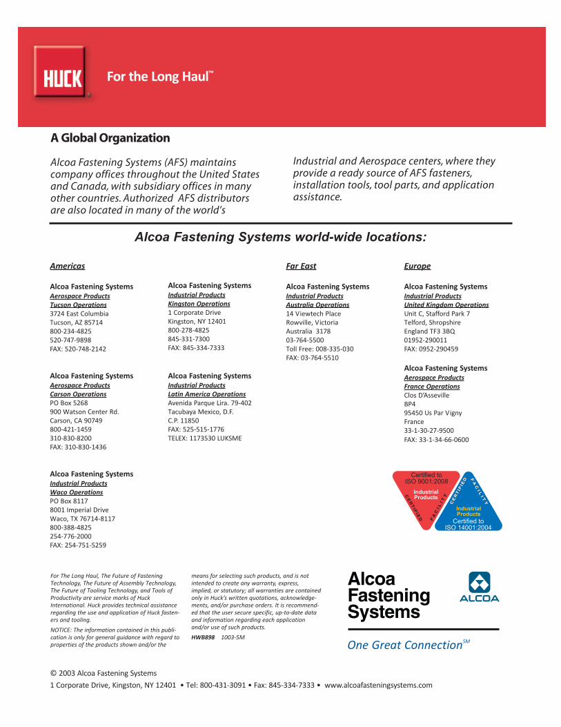
Americas
Alcoa Fastening SystemsAerospace ProductsTucson Operations3724 East ColumbiaTucson, AZ 85714800‐234‐4825520‐747‐9898FAX: 520‐748‐2142
Alcoa Fastening SystemsAerospace ProductsCarson OperationsPO Box 5268900 Watson Center Rd.Carson, CA 90749800‐421‐1459310‐830‐8200FAX: 310‐830‐1436
Alcoa Fastening SystemsIndustrial ProductsWaco OperationsPO Box 81178001 Imperial DriveWaco, TX 76714‐8117800‐388‐4825254‐776‐2000FAX: 254‐751‐5259
Alcoa Fastening SystemsIndustrial ProductsKingston Operations1 Corporate DriveKingston, NY 12401800‐278‐4825845‐331‐7300FAX: 845‐334‐7333
Alcoa Fastening SystemsIndustrial ProductsLatin America OperationsAvenida Parque Lira. 79‐402Tacubaya Mexico, D.F.C.P. 11850FAX: 525‐515‐1776TELEX: 1173530 LUKSME
Far East
Alcoa Fastening SystemsIndustrial ProductsAustralia Operations14 Viewtech PlaceRowville, Victoria Australia 317803‐764‐5500Toll Free: 008‐335‐030FAX: 03‐764‐5510
Europe
Alcoa Fastening SystemsIndustrial ProductsUnited Kingdom OperationsUnit C, Stafford Park 7Telford, ShropshireEngland TF3 3BQ01952‐290011FAX: 0952‐290459
Alcoa Fastening SystemsAerospace ProductsFrance OperationsClos D’AssevilleBP495450 Us Par VignyFrance33‐1‐30‐27‐9500FAX: 33‐1‐34‐66‐0600
A Global Organization
Alcoa Fastening Systems (AFS) maintainscompany offices throughout the United Statesand Canada, with subsidiary offices in manyother countries. Authorized AFS distributorsare also located in many of the world’s
Industrial and Aerospace centers, where theyprovide a ready source of AFS fasteners,installation tools, tool parts, and applicationassistance.
For The Long Haul, The Future of FasteningTechnology, The Future of Assembly Technology,The Future of Tooling Technology, and Tools ofProductivity are service marks of HuckInternational. Huck provides technical assistanceregarding the use and application of Huck fasten‐ers and tooling.NOTICE: The information contained in this publi‐cation is only for general guidance with regard toproperties of the products shown and/or the
means for selecting such products, and is notintended to create any warranty, express,implied, or statutory; all warranties are containedonly in Huck’s written quotations, acknowledge‐ments, and/or purchase orders. It is recommend‐ed that the user secure specific, up‐to‐date dataand information regarding each applicationand/or use of such products.HWB898 1003‐5M
© 2003 Alcoa Fastening Systems1 Corporate Drive, Kingston, NY 12401 • Tel: 800‐431‐3091 • Fax: 845‐334‐7333 • www.alcoafasteningsystems.com
������������ ����������
���������� �����
������������ ���������
���������� �����
One Great ConnectionSM
Alcoa Fastening Systems world-wide locations:
For the Long Haul™