Embed Size (px)
Citation preview
2D Calibration and Metrology Techniques
Dr. David J. Michael Director of Core Vision R & D
Cognex Corporation
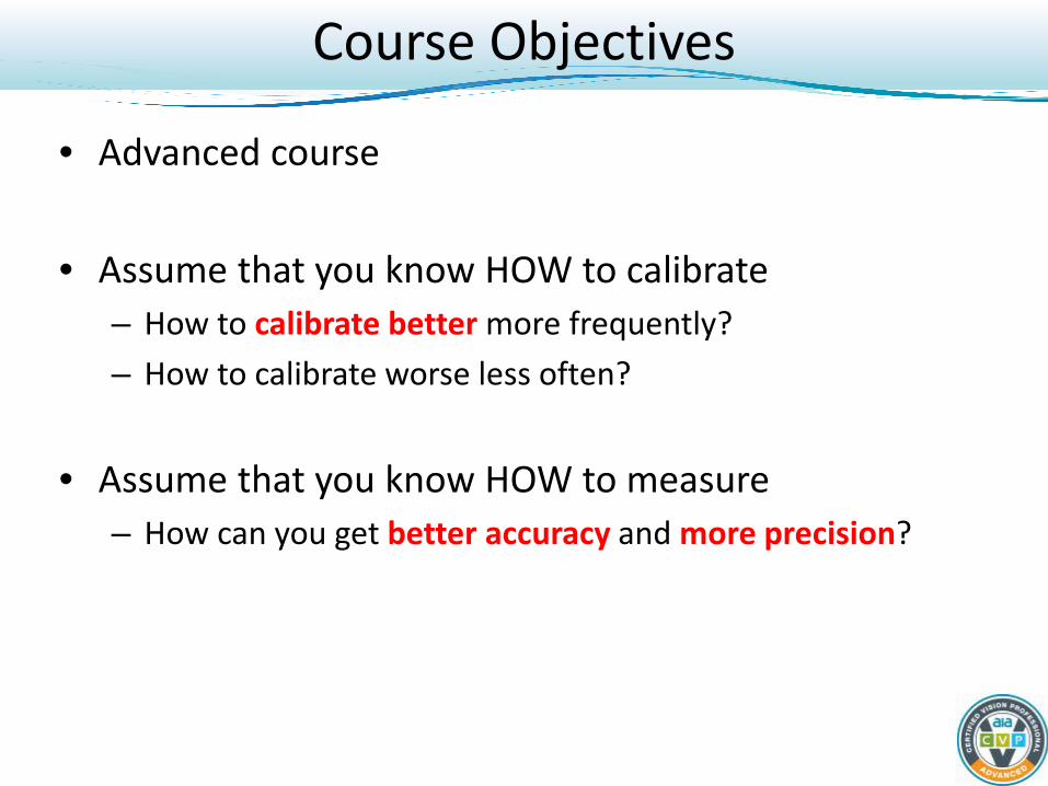
• Advanced course
• Assume that you know HOW to calibrate – How to calibrate better more frequently? – How to calibrate worse less often?
• Assume that you know HOW to measure – How can you get better accuracy and more precision?
Course Objectives
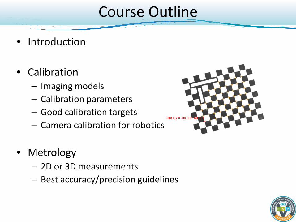
Course Outline
• Introduction
• Calibration – Imaging models – Calibration parameters – Good calibration targets – Camera calibration for robotics
• Metrology
– 2D or 3D measurements – Best accuracy/precision guidelines
Calibration - What is it?
All vision tools operate in the pixel world
What does a length of 209.41 pixels mean?
The meaning depends on the camera and environment: 1. Camera/image acquisition details 2. Physical location and angles of the camera relative to target 3. Optics (lens)
Calibrate to get real-world, meaningful measurements. This relates the world coordinate system to camera coordinate system.
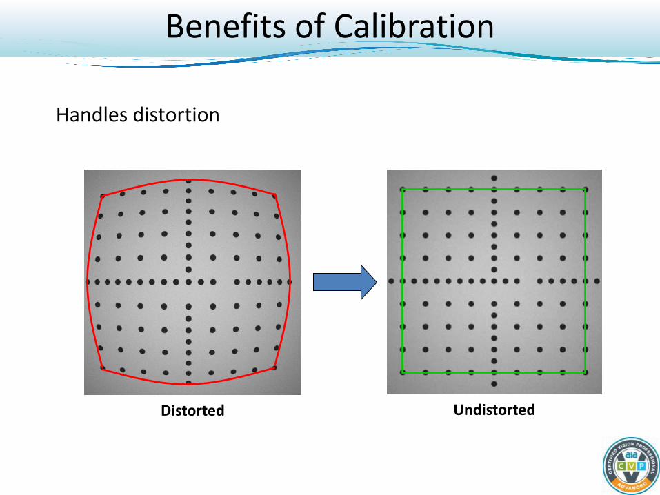
Benefits of Calibration
Handles distortion
Distorted Undistorted
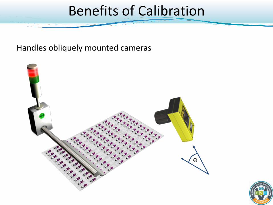
Benefits of Calibration
Handles obliquely mounted cameras
Θ
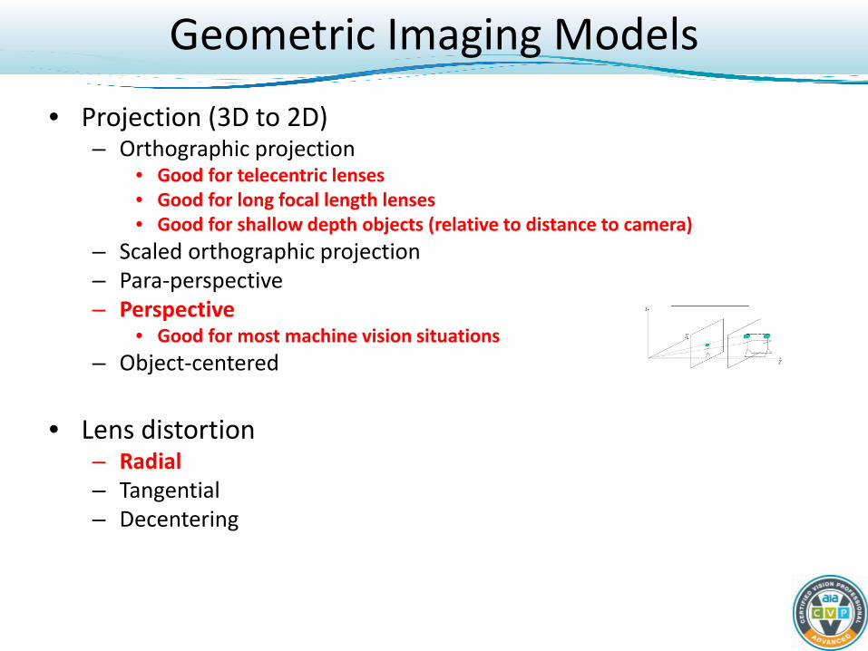
Geometric Imaging Models
• Projection (3D to 2D) – Orthographic projection
• Good for telecentric lenses • Good for long focal length lenses • Good for shallow depth objects (relative to distance to camera)
– Scaled orthographic projection – Para-perspective – Perspective
• Good for most machine vision situations – Object-centered
• Lens distortion
– Radial – Tangential – Decentering
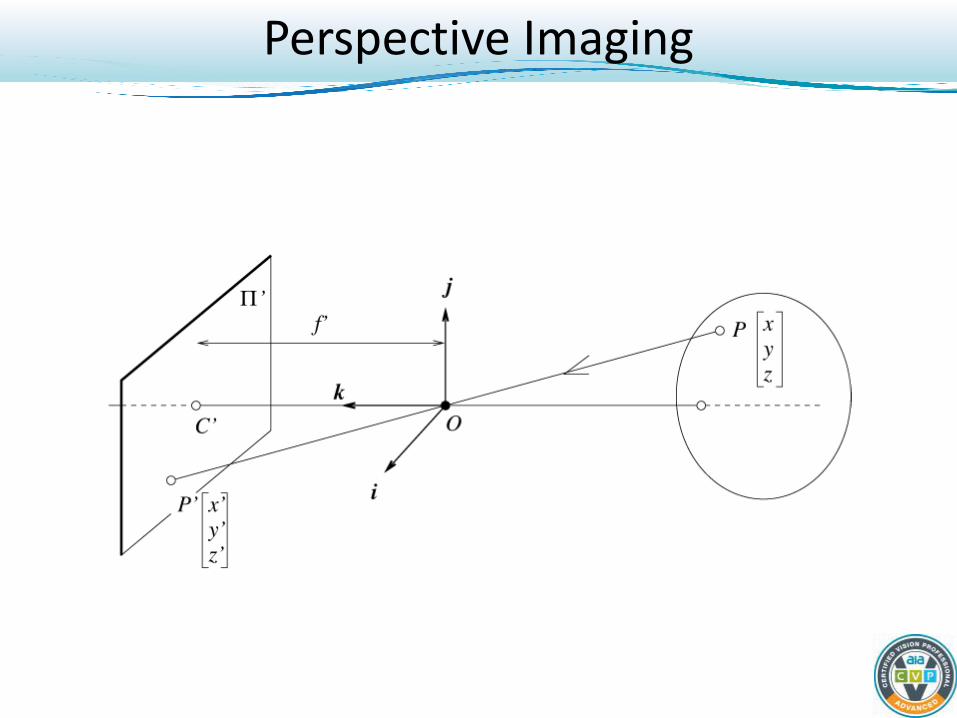
Perspective Imaging
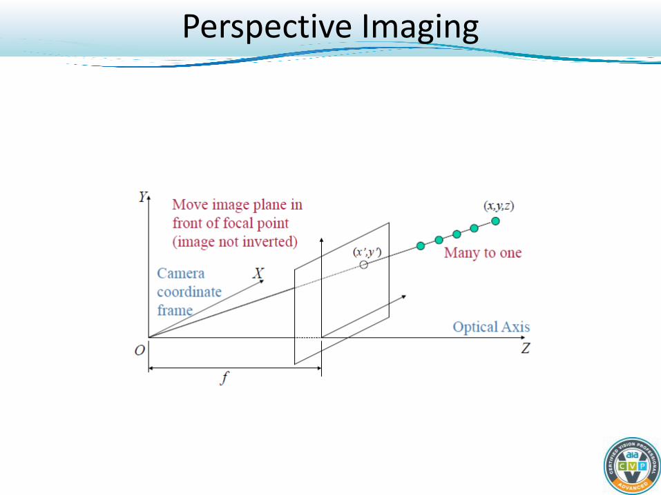
Perspective Imaging
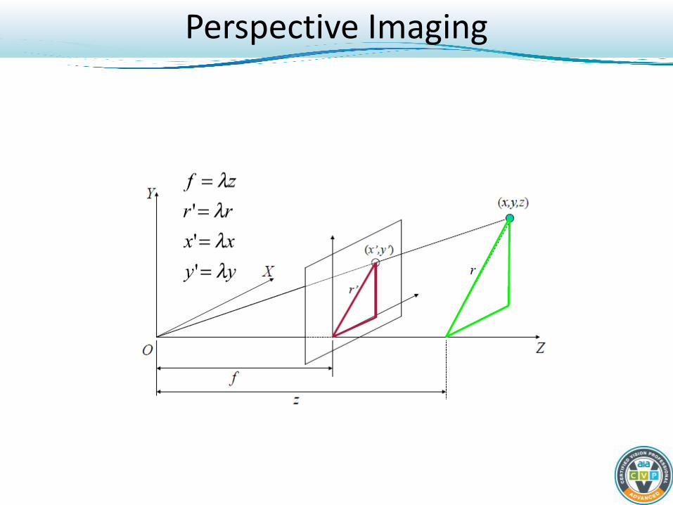
Perspective Imaging

Perspective Imaging
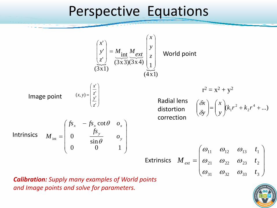
Perspective Equations
)1x4(1)4x3(3)x(3
int
1)x(3'''
=
zyx
extMMzyx
=
''''
),(
zyzx
yx
World point
r2 = x2 + y2 Image point
...)( 42
21 ++
=
rkrkyx
yxδδRadial lens
distortion correction
Intrinsics
Extrinsics
−
=
100sin
0
cot
int yy
xxx
ofs
ofsfs
Mθ
θ
=
3333231
2232221
1131211
ttt
M ext
ωωωωωωωωω
Calibration: Supply many examples of World points and Image points and solve for parameters.
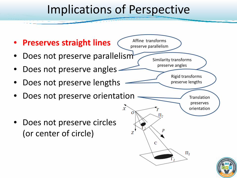
Implications of Perspective • Preserves straight lines • Does not preserve parallelism • Does not preserve angles • Does not preserve lengths • Does not preserve orientation
• Does not preserve circles
(or center of circle)
Affine transforms preserve parallelism
Similarity transforms preserve angles
Rigid transforms preserve lengths
Translation preserves
orientation
Calibration Parameters – Intrinsic Camera Parameters
• Each camera has independent intrinsics
• Focal Length (f) • Principal point
– Where the optical axis of the camera pierces the imaging array (ox, oy)
– Calibrated mathematical origin in the image
• Pixel size (sx,sy) • Non-orthogonality of x and y axes (skew angle Θ) • Lens distortion parameters (typically radial)
• Each camera has independent intrinsics!
• What causes intrinsics to change requiring recalibration? – Changing ANY lens setting including refocusing – Swapping the camera
Calibration Parameters – Intrinsic Camera Parameters
• Each camera has independent extrinsics!
• Physical relationship of camera to world coordinate system
• 6 degrees of freedom translation t and rotation ω
• What changes extrinsics to change requiring recalibration? – Moving or bumping the camera position – Swapping the camera
Calibration Parameters – Extrinsic Camera Parameters
When Does Calibration Allow One-to-one Mapping?
• One-to-one mapping means that one 2D point in the image corresponds to one 3D point in the world. – 2D points can be used for 3D measurements with one-to-one
mapping
• If objects are planar and lie on a plane or if they lie at a known depth, then this type of single camera calibration will allow 2D image measurements to imply unique 3D object measurements
• If the features are not on a plane or at a known depth, a single calibrated camera only finds 3D RAYS not 3D points – 3D metrology should be used with non-planar features to give
high accuracy measurements
Calibration Targets
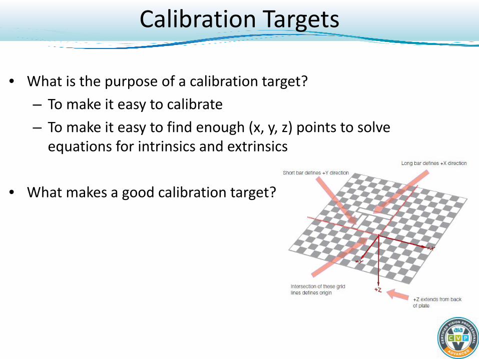
• What is the purpose of a calibration target? – To make it easy to calibrate – To make it easy to find enough (x, y, z) points to solve
equations for intrinsics and extrinsics
• What makes a good calibration target?
Calibration Targets
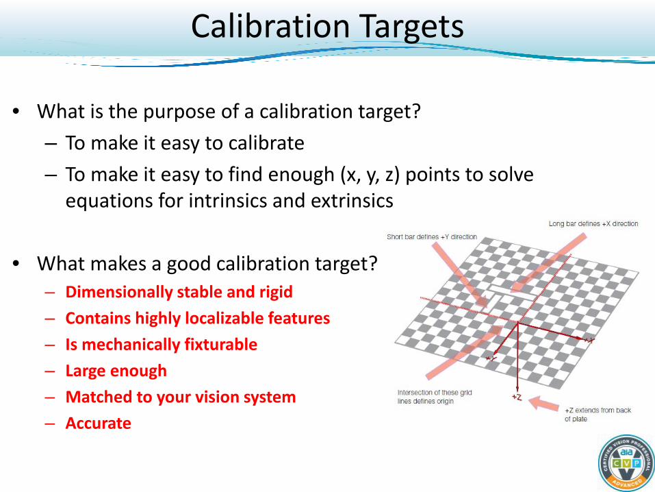
• What is the purpose of a calibration target? – To make it easy to calibrate – To make it easy to find enough (x, y, z) points to solve
equations for intrinsics and extrinsics
• What makes a good calibration target? – Dimensionally stable and rigid – Contains highly localizable features – Is mechanically fixturable – Large enough – Matched to your vision system – Accurate
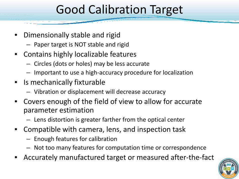
Good Calibration Target
• Dimensionally stable and rigid – Paper target is NOT stable and rigid
• Contains highly localizable features – Circles (dots or holes) may be less accurate – Important to use a high-accuracy procedure for localization
• Is mechanically fixturable – Vibration or displacement will decrease accuracy
• Covers enough of the field of view to allow for accurate parameter estimation – Lens distortion is greater farther from the optical center
• Compatible with camera, lens, and inspection task – Enough features for calibration – Not too many features for computation time or correspondence
• Accurately manufactured target or measured after-the-fact
Why Good Calibration Accuracy is Desirable?
• Contributes to good measurement accuracy • Detects problems in system or set-up • Estimates what is possible for your system
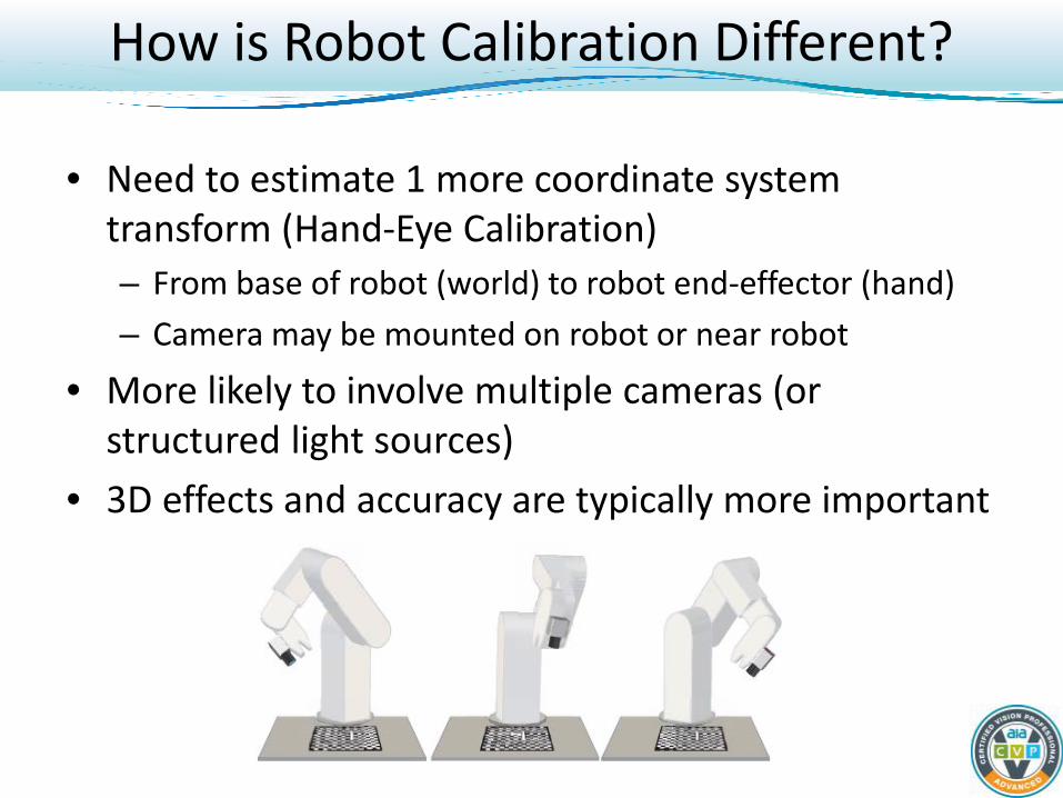
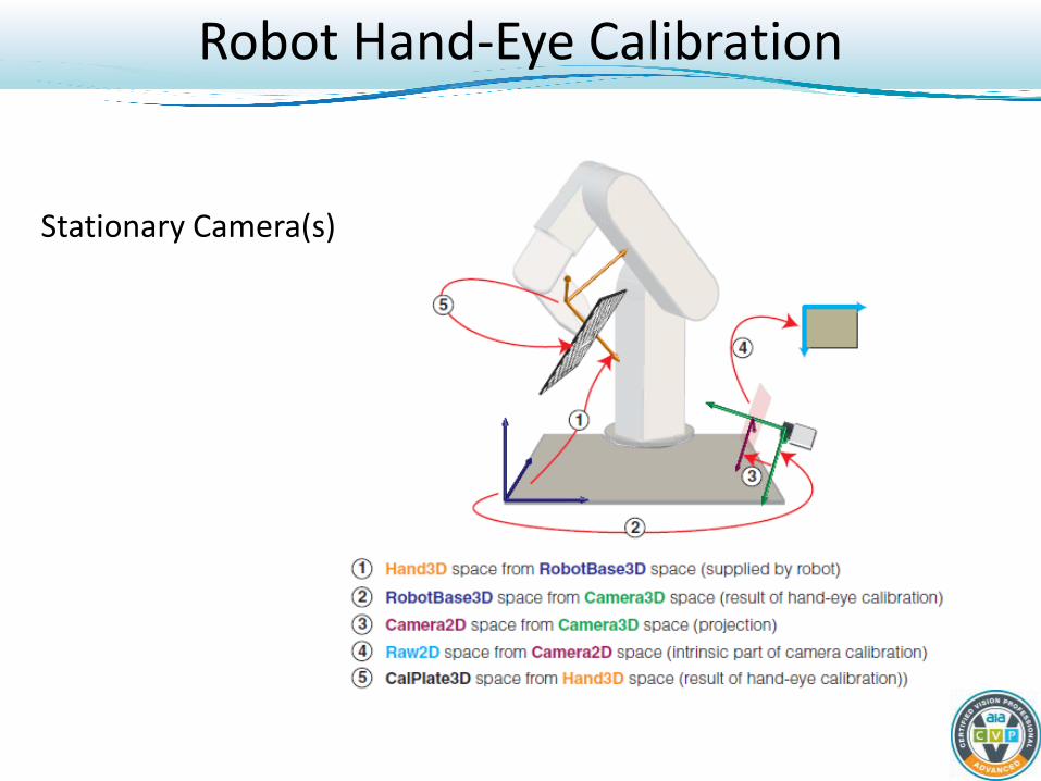
How is Robot Calibration Different?
• Need to estimate 1 more coordinate system transform (Hand-Eye Calibration) – From base of robot (world) to robot end-effector (hand) – Camera may be mounted on robot or near robot
• More likely to involve multiple cameras (or structured light sources)
• 3D effects and accuracy are typically more important
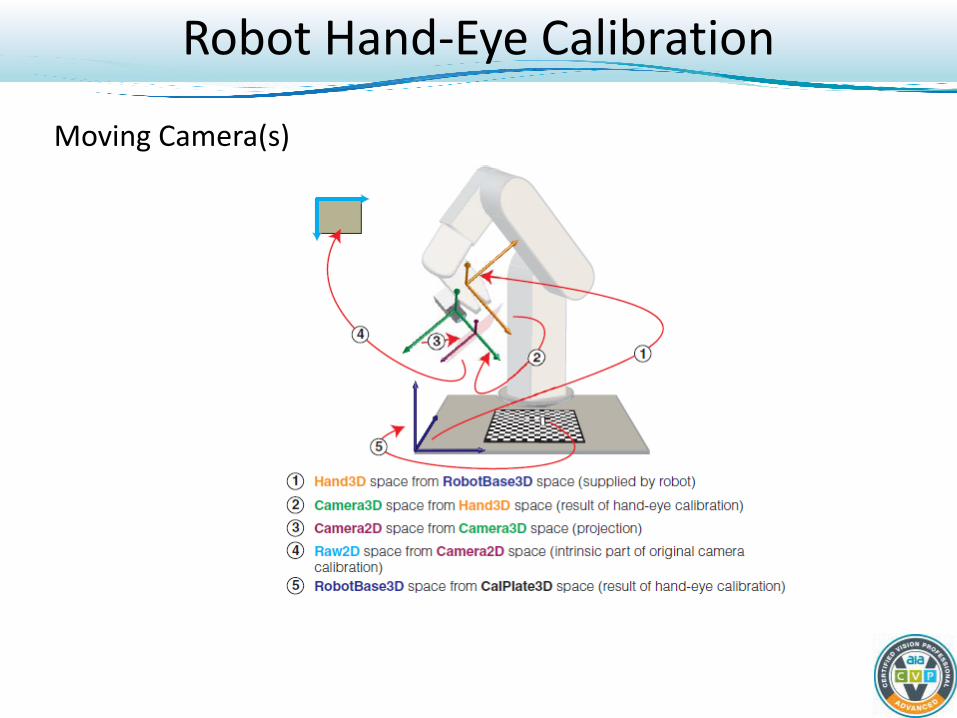
Robot Hand-Eye Calibration
Moving Camera(s)
Robot Hand-Eye Calibration
Stationary Camera(s)
Metrology
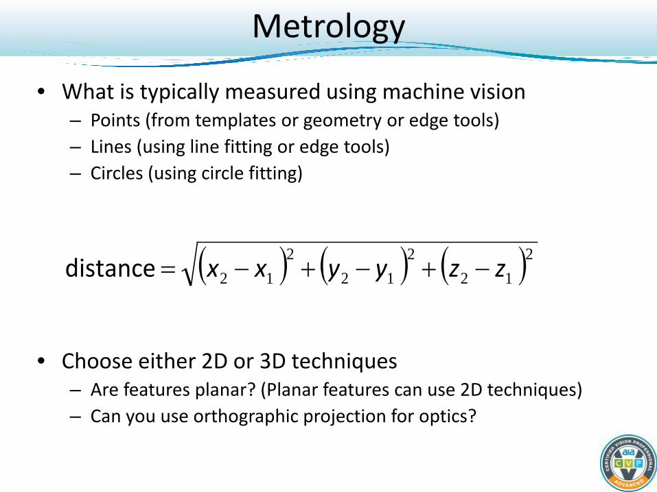
• What is typically measured using machine vision – Points (from templates or geometry or edge tools) – Lines (using line fitting or edge tools) – Circles (using circle fitting)
• Choose either 2D or 3D techniques – Are features planar? (Planar features can use 2D techniques) – Can you use orthographic projection for optics?
( ) ( ) ( )2122
122
12 zzyyxx −+−+−=distance
How Accurately Can I Gauge? • What part are you inspecting?
– Smooth edges are optimal; burrs/ rough edges will reduce accuracy
How Accurately Can I Gauge? • What part are you inspecting?
– Smooth edges are optimal; burrs/ rough edges will reduce accuracy
• How accurately is the calibration grid printed/manufactured? – A grid printed on a standard ink jet or laser jet printer will limit accuracy
How Accurately Can I Gauge? • What part are you inspecting?
– Smooth edges are optimal; burrs/ rough edges will reduce accuracy
• How accurately is the calibration grid printed/manufactured? – A grid printed on a standard ink jet or laser jet printer will limit accuracy
• How good is your lens? – High quality lenses with telecentric properties will provide best results
• How well is the camera mounted? – Vibrations can cause camera movement over time
• What is the image quality? – High gain increases pixel jitter; Pixel saturation reduces accuracy
• How accurate are the vision tools? – Edge tools are accurate to .25 (1/4) pixel, PatMax to .025 (1/40) pixel
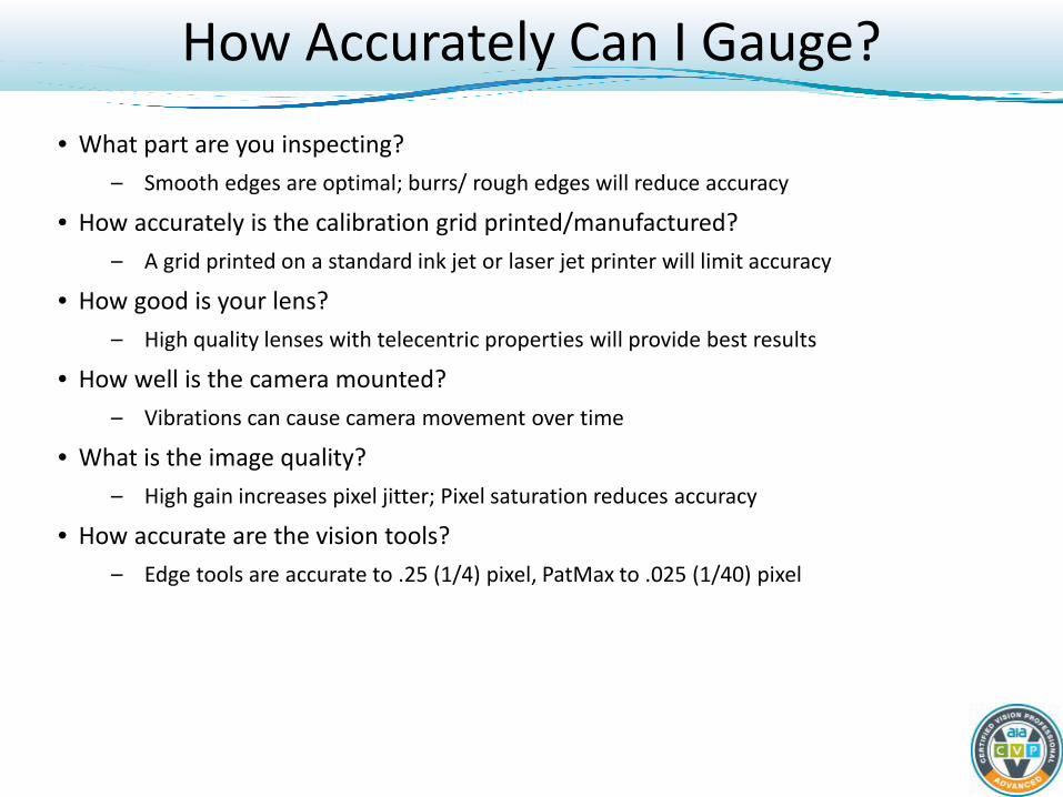
• Overall worst case is the sum of these errors. – These tend to be additive, and seldom cancel each other out – 1/10th pixel accuracy is attainable if the parts are flat and have well defined edges
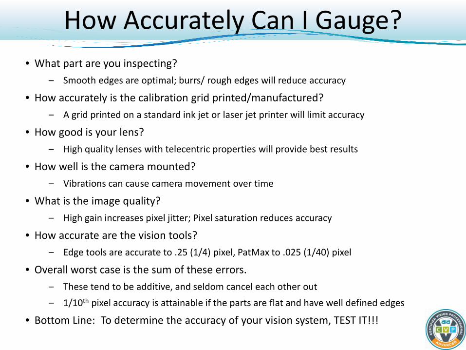
• Bottom Line: To determine the accuracy of your vision system, TEST IT!!!
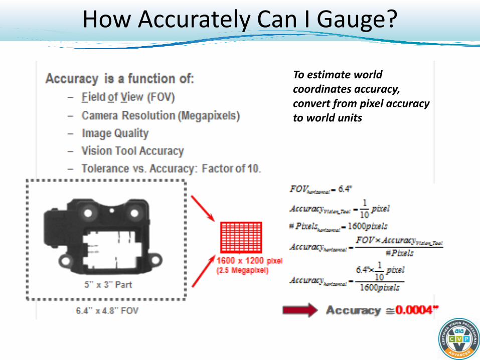
How Accurately Can I Gauge?
To estimate world coordinates accuracy, convert from pixel accuracy to world units
Guidelines for Metrology --- Calibration
• Keep calibration setup identical to production setup - Keep calibration object & part in same plane - Limit calibration to region of image containing features
of interest
• Calibrate periodically – whenever you think setup may change (each shift, daily, etc.)
• Choose good calibration target
36
Guidelines for Metrology – Optics & Fixturing
• Mount the camera well – Rigidly – Vibration-free
• Choose high quality and/or telecentric lenses for best
results – Calibrating a poor quality lens is not equivalent to using a high
quality lens
• Secure the lens to the camera – Before calibration
• Fixture the object well
Guidelines for Metrology – Imaging and Vision Tools
• Choose features with smooth edges at selected resolution – Burrs/rough edges will reduce accuracy
• Select camera/illumination/exposure/gain/contrast for
good image quality – Choose settings to minimize jitter – Choose settings to avoid saturation
• Choose accurate-enough vision tools for desired accuracy
– Edge tools may have accuracy of ¼ pixel – PatMax may have accuracy of 1/40 pixel
• Choose 3D techniques if necessary

Dr. David J. Michael Director of Core Vision R & D
Cognex Corporation One Vision Drive Natick, Massachusetts USA
Phone: +1 (508) 650-3000 Email: [email protected]
www.cognex.com