Embed Size (px)
Citation preview
2D preobrazba (morphing)
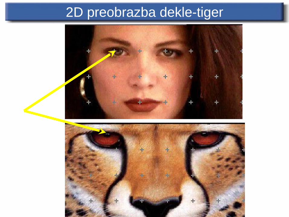
2D preobrazba dekle-tiger
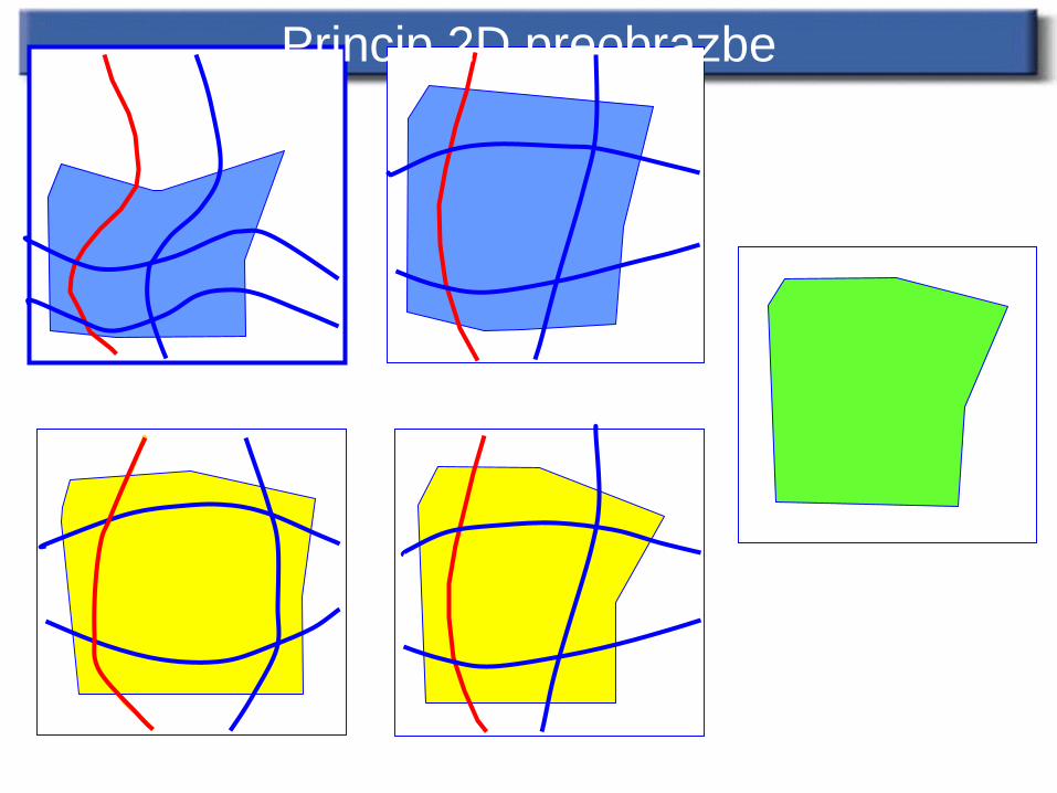
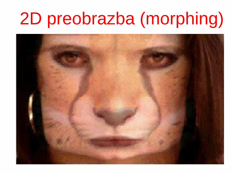
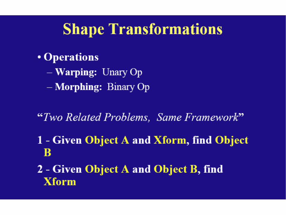
Princip 2D preobrazbe
Uvod
• Morphing – derived from the word metamorphosis.
• Metamorphosis means to change shape, appearance or form.Example:
Kaj je preobrazba?
• Morphing can be defined as:
- Transition from one object to another.
- Process of transforming one image into another.
• An animation technique that allows you to blend two
still images, creating a sequence of in – between
pictures that when played in Quick Time,
metamorphoses the first image into the second.
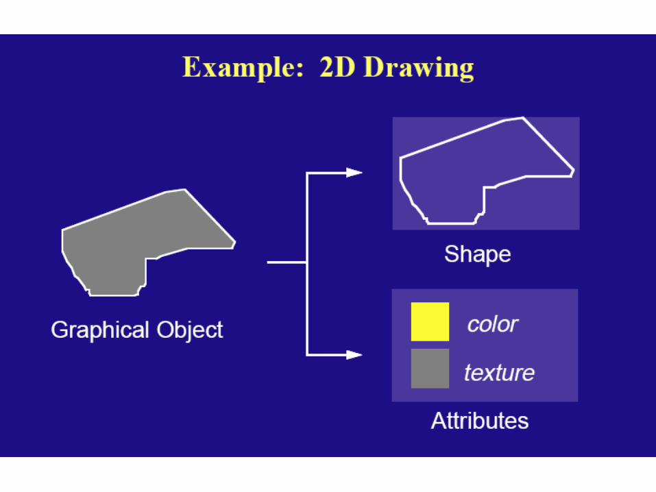
Kaj je preobrazba slike?
Creating a smooth transition between two images
3D model based or Image based Used for obtaining special effects
Tehnike preobrazbe slike
Crossdissolve Field morphing Mesh morphing Radial Basis Functions (RBF) Energy minimization Multilevel FreeForm Deformation (MFFD)
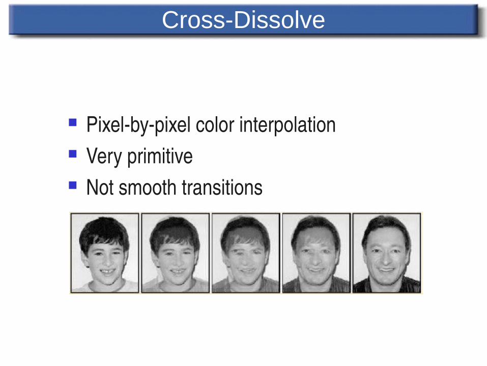
Cross-Dissolve
Pixelbypixel color interpolation Very primitive Not smooth transitions
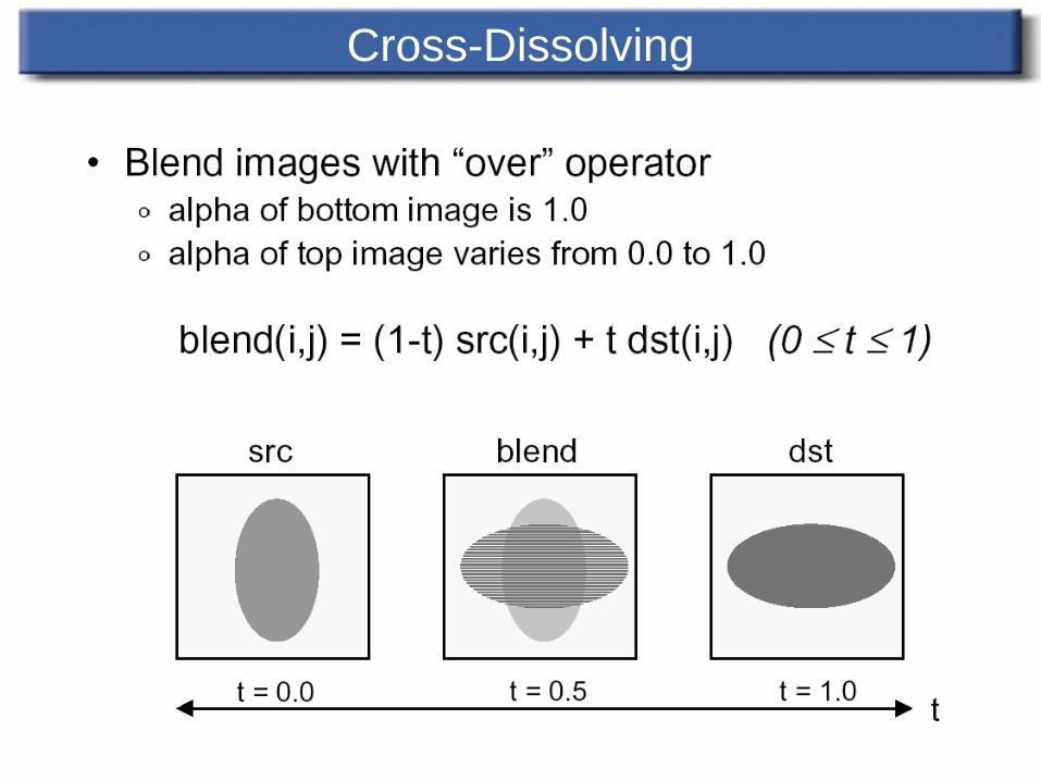
Cross-Dissolving
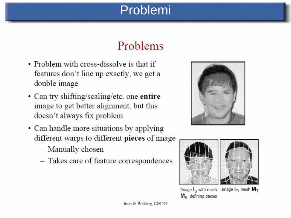
Problemi
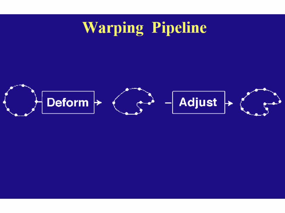
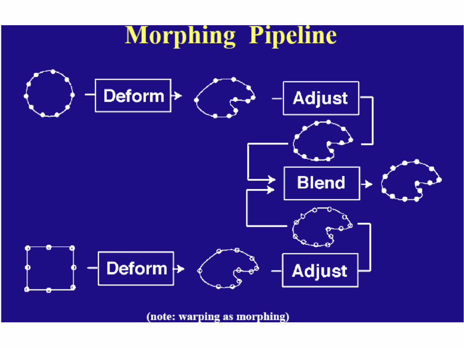
Mesh Warping
Source and target images are meshed The meshes for both images are interpolated The intermediate images are crossdissolved
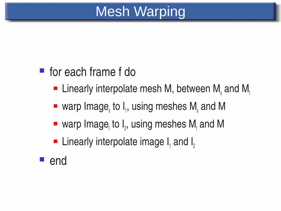
Mesh Warping
for each frame f do Linearly interpolate mesh M, between Ms and Mt
warp Images to I1, using meshes Ms and M warp Imaget to I2, using meshes Mt and M Linearly interpolate image I1 and I2
end
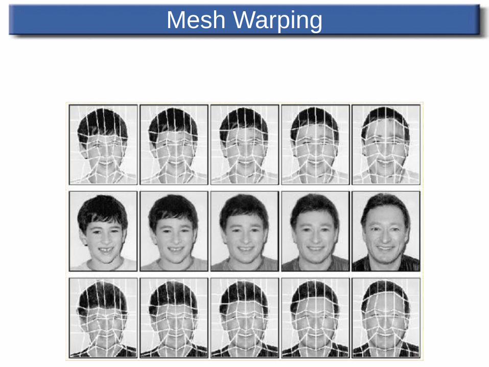
Mesh Warping
Mesh Warping
Hard to fit the mesh in images All control points affect the warping equally Not enough control in certain areas when
needed
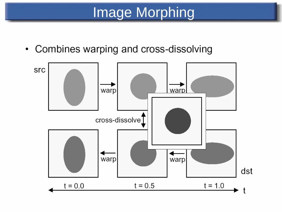
Image Morphing
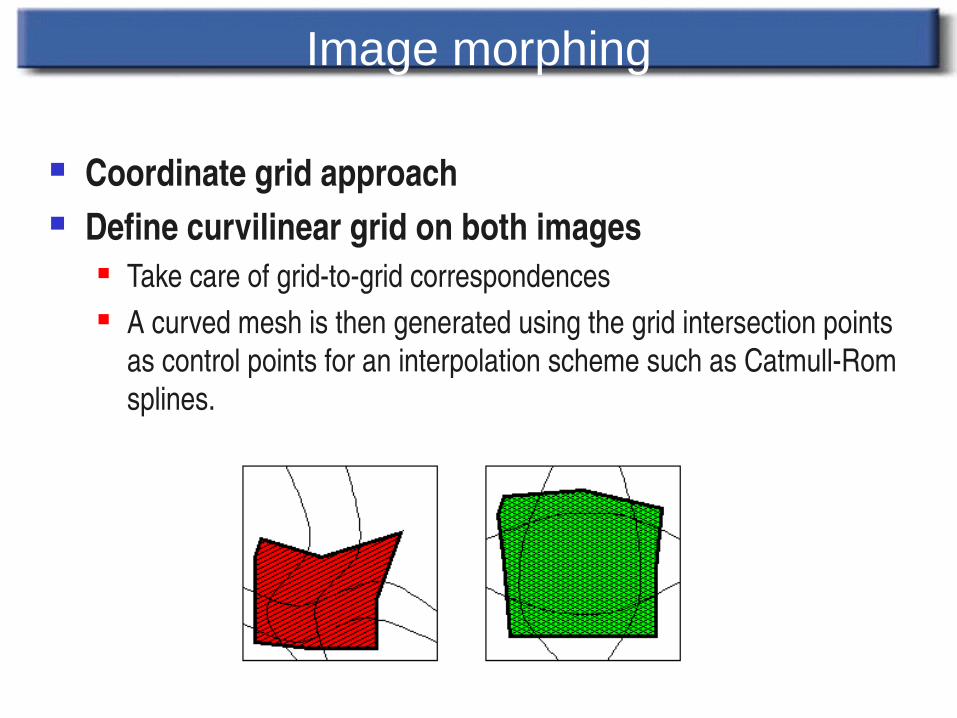
Image morphing
Coordinate grid approach Define curvilinear grid on both images
Take care of gridtogrid correspondences A curved mesh is then generated using the grid intersection points
as control points for an interpolation scheme such as CatmullRom splines.
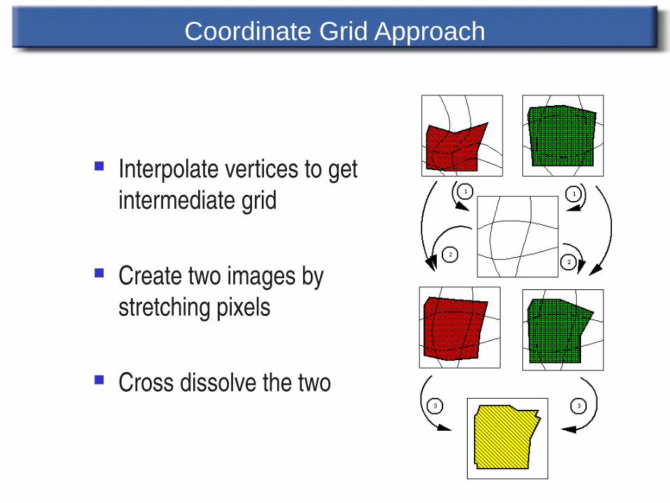
Coordinate Grid Approach
Interpolate vertices to get intermediate grid
Create two images by stretching pixels
Cross dissolve the two
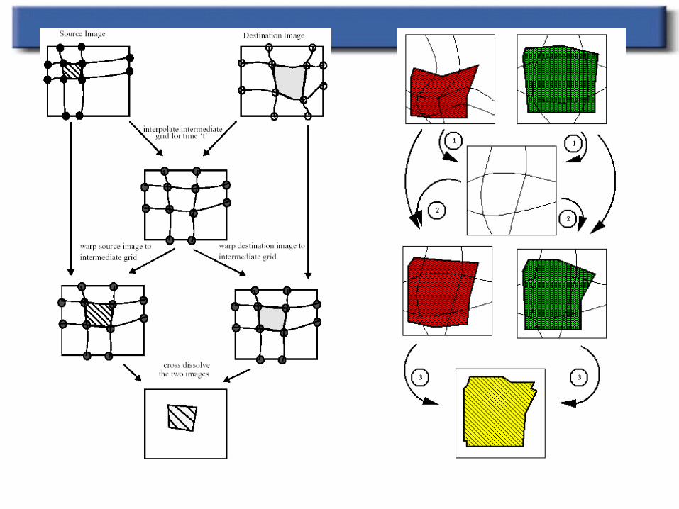
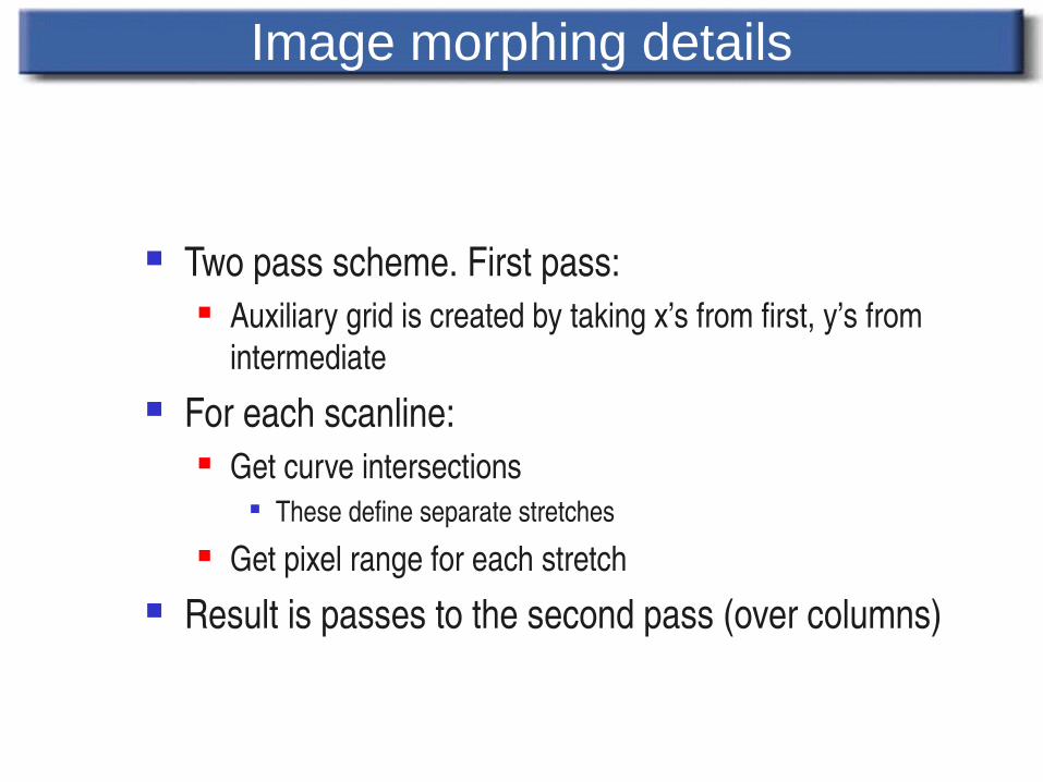
Image morphing details
Two pass scheme. First pass: Auxiliary grid is created by taking x’s from first, y’s from
intermediate For each scanline:
Get curve intersections These define separate stretches
Get pixel range for each stretch Result is passes to the second pass (over columns)
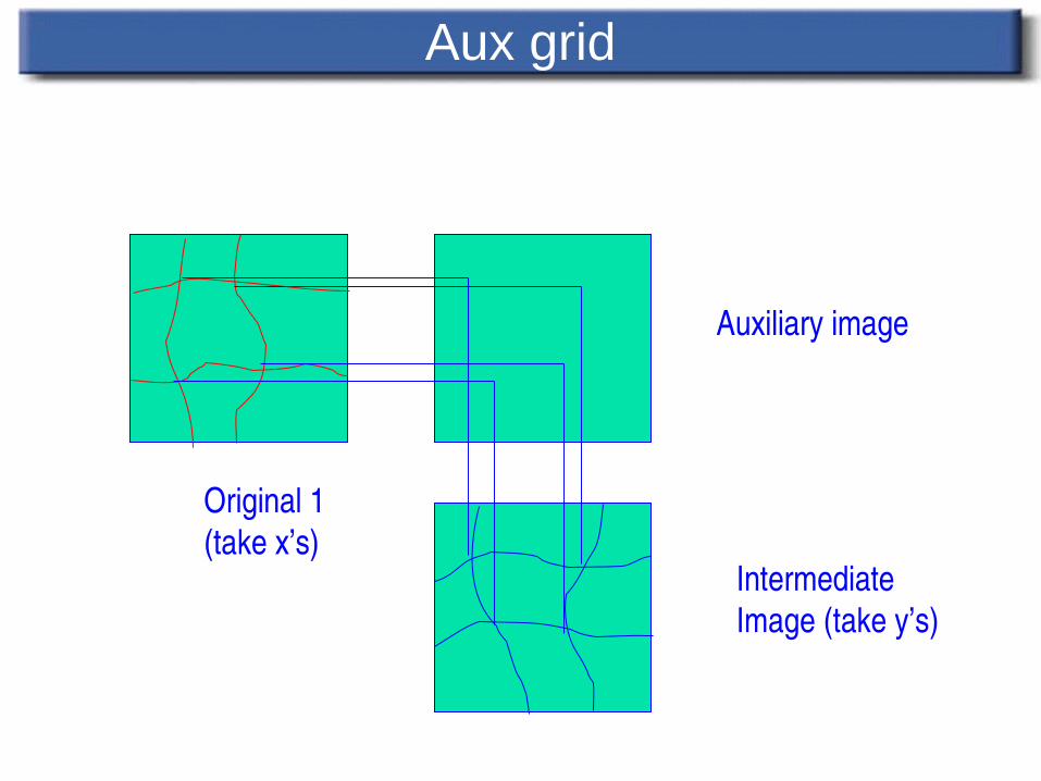
Aux grid
Original 1(take x’s)
IntermediateImage (take y’s)
Auxiliary image
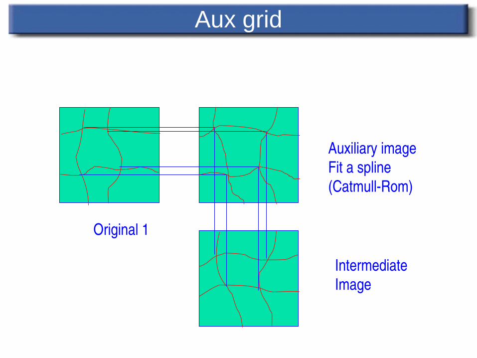
Aux grid
Original 1
IntermediateImage
Auxiliary imageFit a spline(CatmullRom)
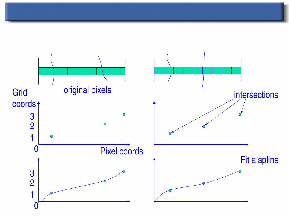
Pixel splatting (for each scanline)
0123
0123
original pixels
Fit a spline
intersections
Pixel coords
Gridcoords
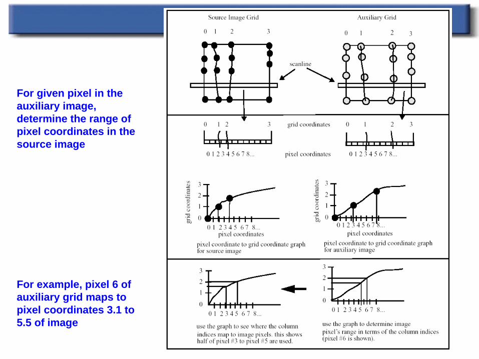
For given pixel in the auxiliary image, determine the range of pixel coordinates in thesource image
For example, pixel 6 of auxiliary grid maps to pixel coordinates 3.1 to 5.5 of image
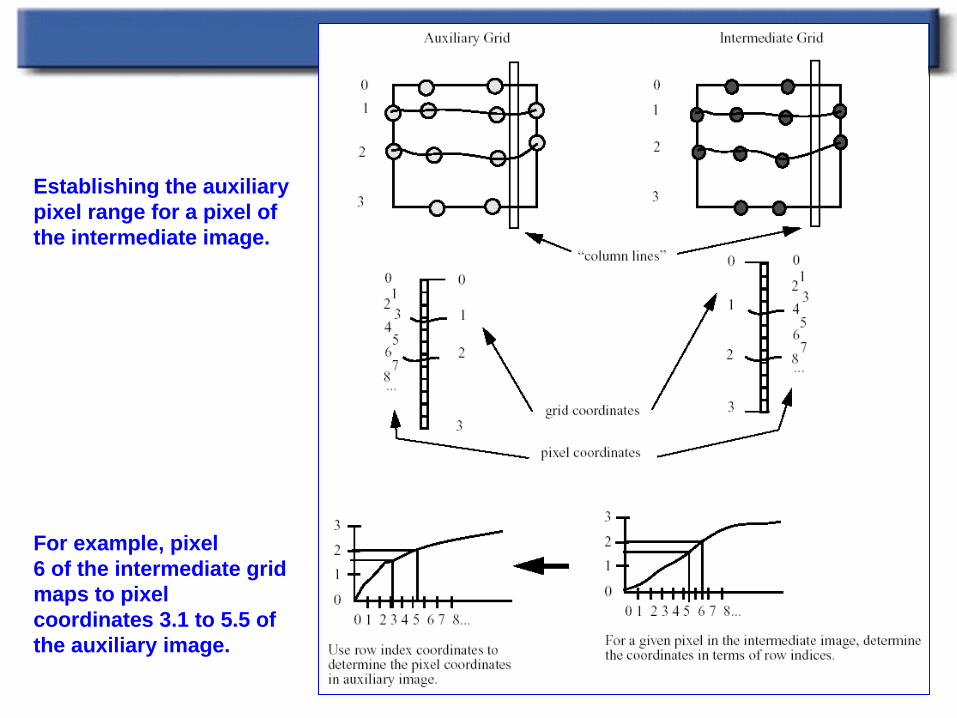
Establishing the auxiliary pixel range for a pixel of the intermediate image.
For example, pixel6 of the intermediate grid maps to pixel coordinates 3.1 to 5.5 of the auxiliary image.
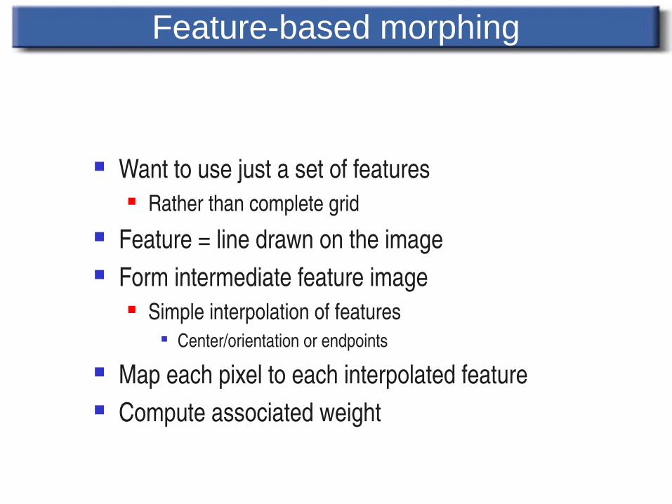
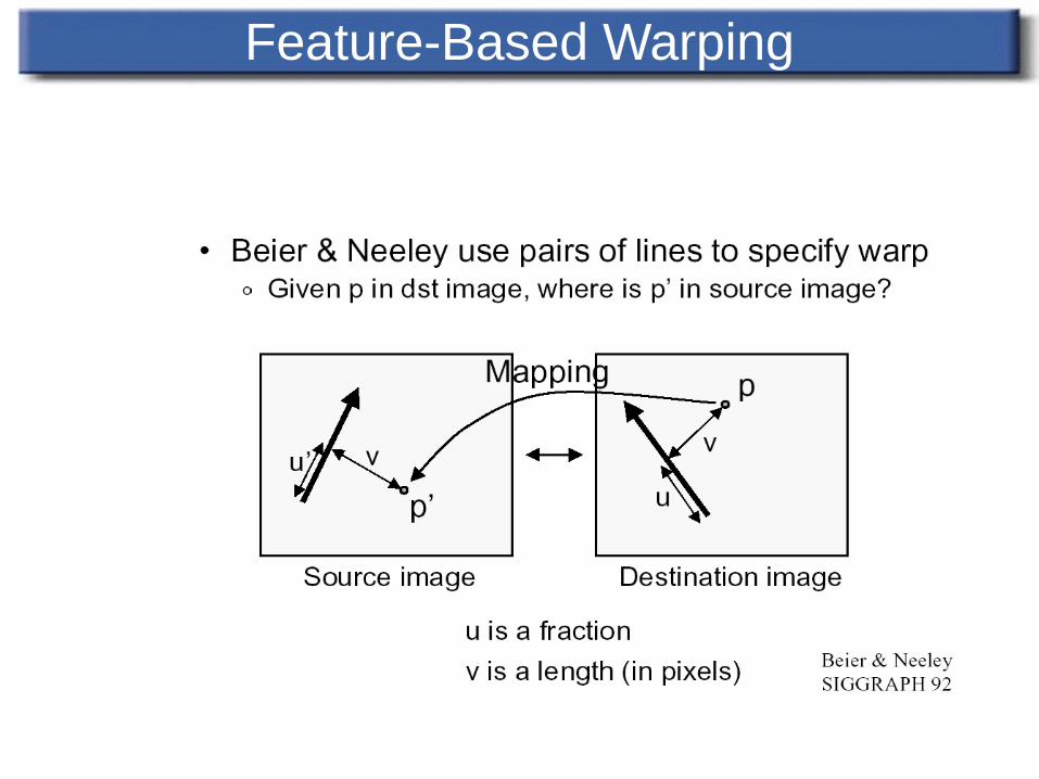
Feature-based morphing
Want to use just a set of features Rather than complete grid
Feature = line drawn on the image Form intermediate feature image
Simple interpolation of features Center/orientation or endpoints
Map each pixel to each interpolated feature Compute associated weight
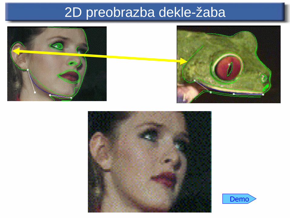
2D preobrazba dekle-žaba
Demo
“Which pixel coordinate in the source image do we sample for each pixel in destination image?”
Correspondence achieved using feature line(s) in source and destination images
Feature-Based Warping
Feature-Based Warping
Transformation with one pair with features(lines) Transformation with multiple pairs of
features(lines)
Feature-Based Warping
A pair of features(lines) – one defined relative to the source image while the other defined relative to destination image
A pair of lines defines a coordinate mapping from destination pixel (denoted X)to source pixel(denoted X’)
Transformation with One Pair of Lines
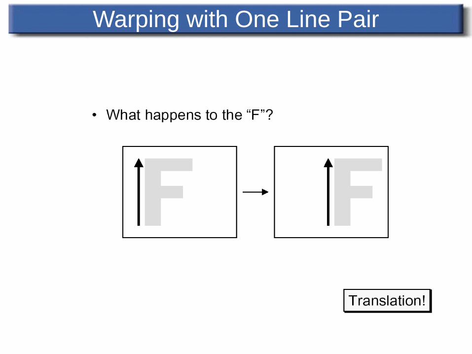
Warping with One Line Pair
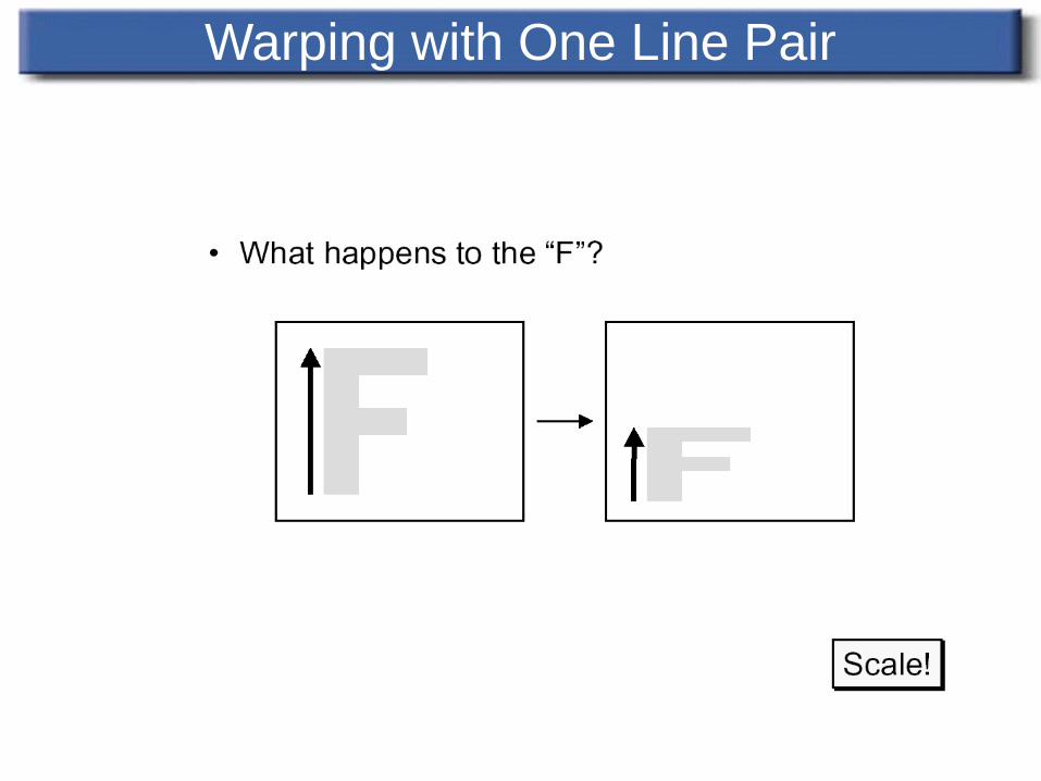
Warping with One Line Pair
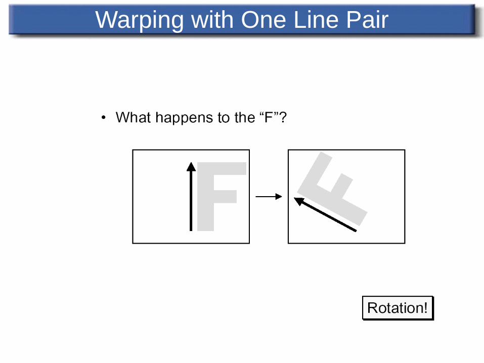
Warping with One Line Pair
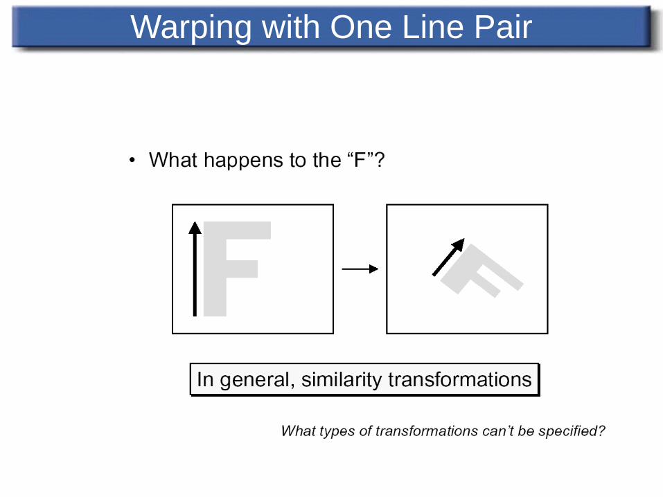
Warping with One Line Pair
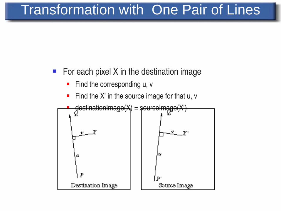
For each pixel X in the destination image Find the corresponding u, v Find the X’ in the source image for that u, v destinationImage(X) = sourceImage(X’)
Transformation with One Pair of Lines
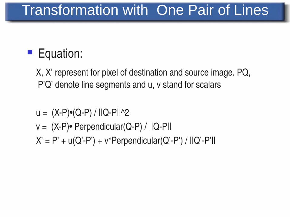
Equation: X, X’ represent for pixel of destination and source image. PQ,
P’Q’ denote line segments and u, v stand for scalars
u = (XP)•(QP) / ||QP||^2 v = (XP)• Perpendicular(QP) / ||QP|| X’ = P’ + u(Q’P’) + v*Perpendicular(Q’P’) / ||Q’P’||
Transformation with One Pair of Lines
Transformation with One Pair of Lines
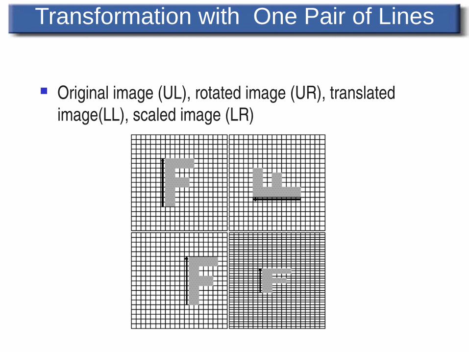
Original image (UL), rotated image (UR), translated image(LL), scaled image (LR)
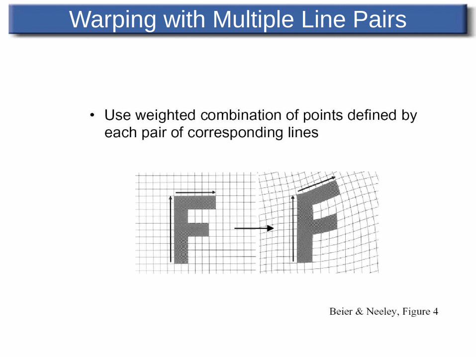
Warping with Multiple Line Pairs
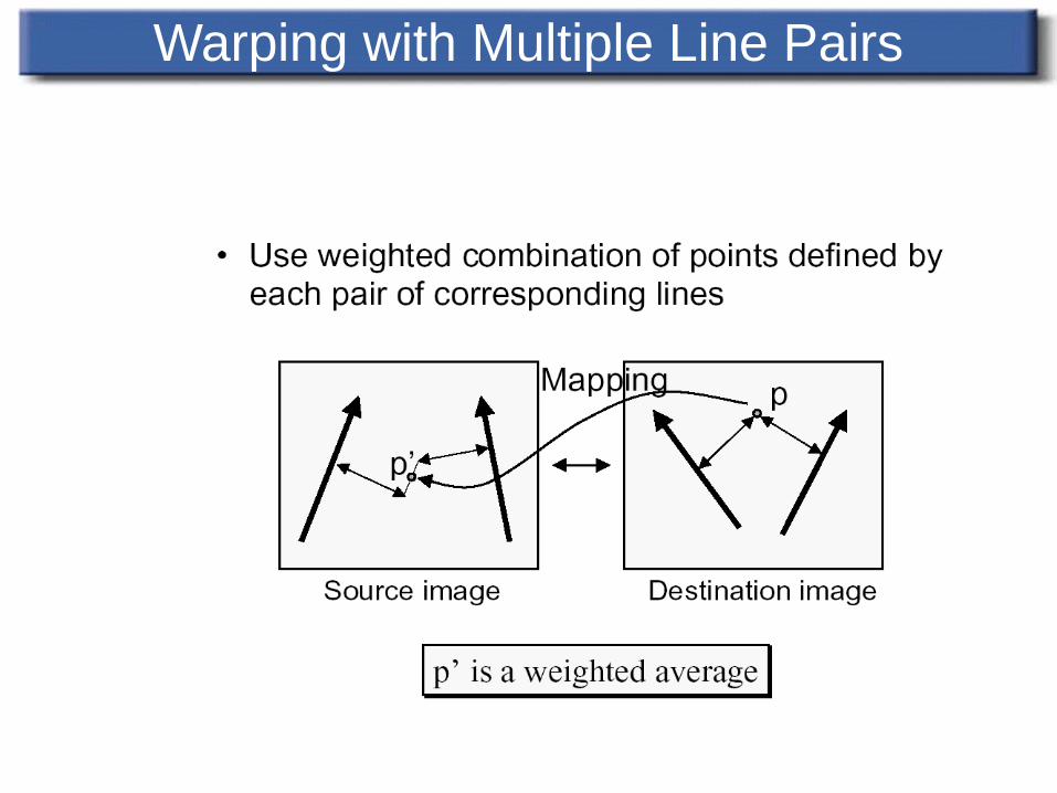
Warping with Multiple Line Pairs
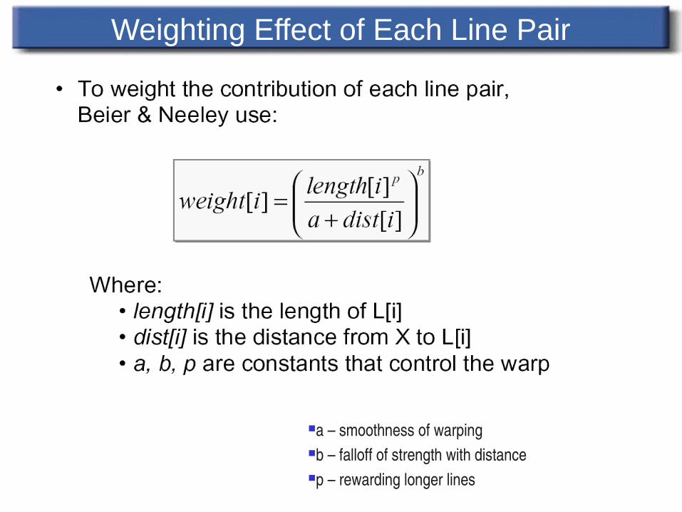
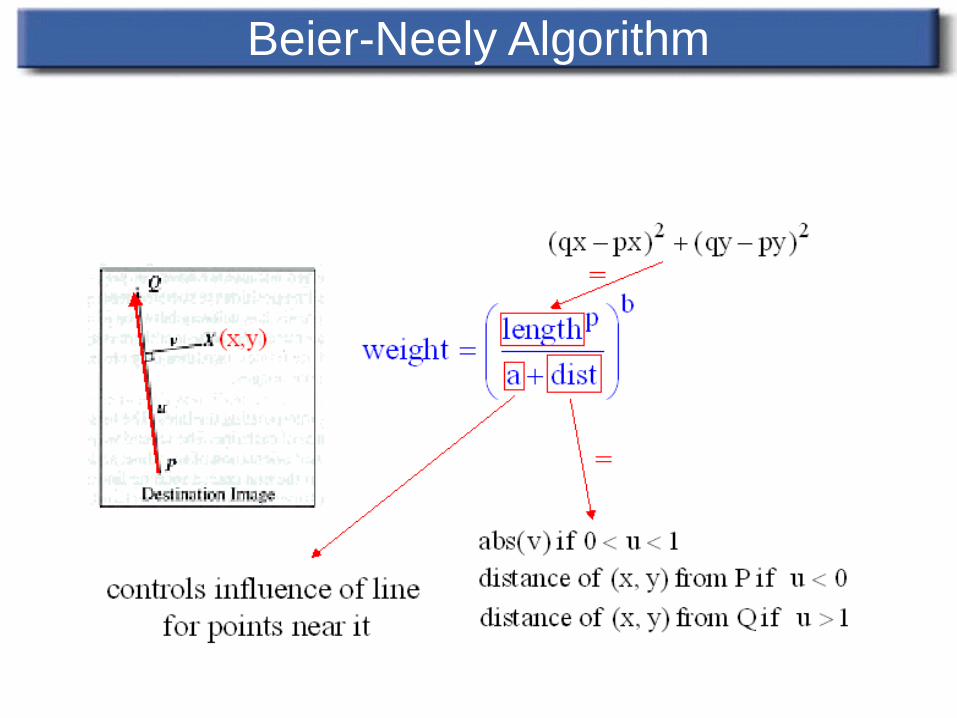
Weighting Effect of Each Line Pair
a – smoothness of warpingb – falloff of strength with distancep – rewarding longer lines
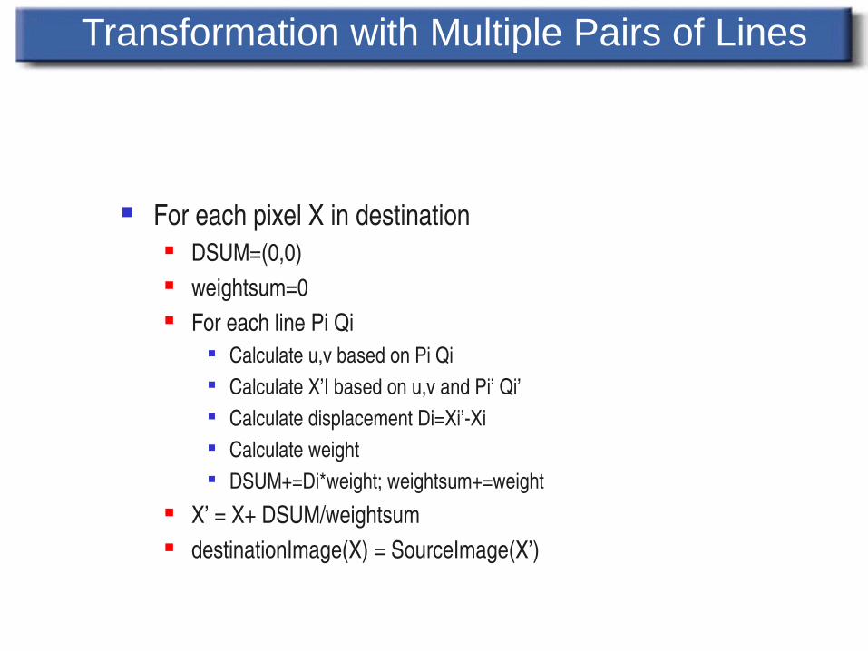
For each pixel X in destination DSUM=(0,0) weightsum=0 For each line Pi Qi
Calculate u,v based on Pi Qi Calculate X’I based on u,v and Pi’ Qi’ Calculate displacement Di=Xi’Xi Calculate weight DSUM+=Di*weight; weightsum+=weight
X’ = X+ DSUM/weightsum destinationImage(X) = SourceImage(X’)
Transformation with Multiple Pairs of Lines
Transformation with Multiple Pairs of Lines
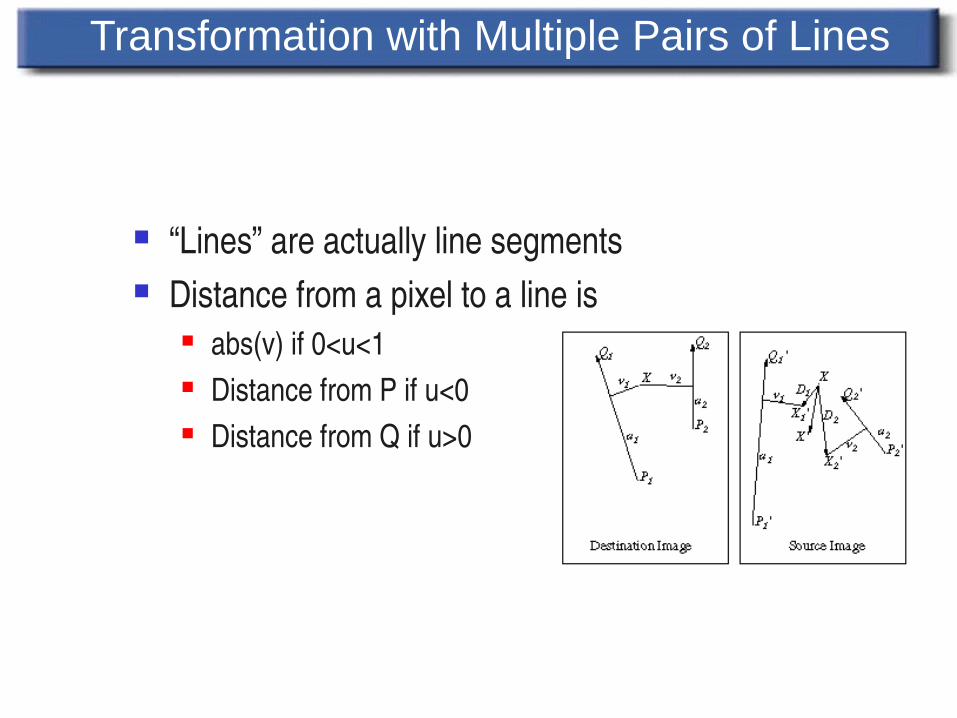
“Lines” are actually line segments Distance from a pixel to a line is
abs(v) if 0<u<1 Distance from P if u<0 Distance from Q if u>0
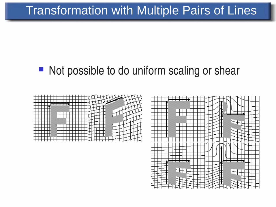
Not possible to do uniform scaling or shear
Transformation with Multiple Pairs of Lines
Advantages Expressive Adding control points is
easy
Disadvantages All line segments need to
be referenced for each pixel
Line segments have global impact
Transformation with Multiple Pairs of Lines
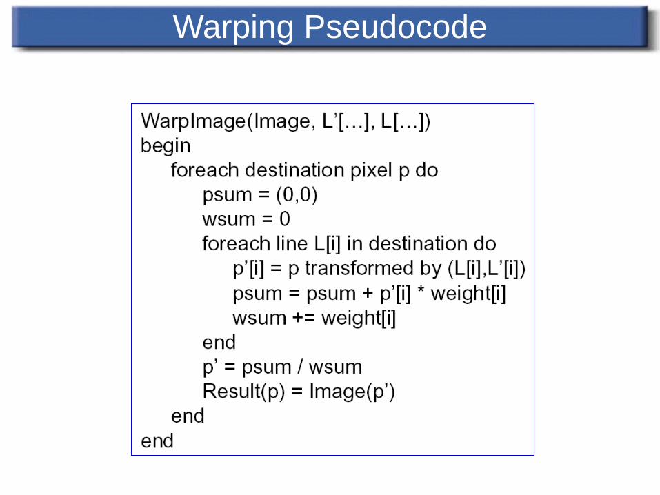
Warping Pseudocode
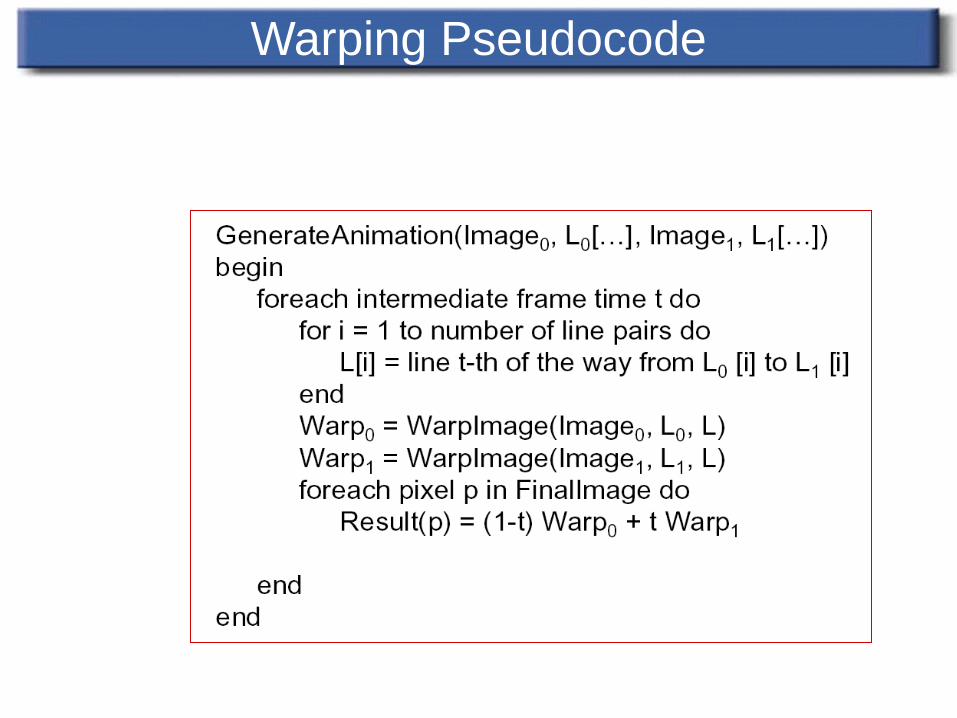
Warping Pseudocode
Morphing between two images
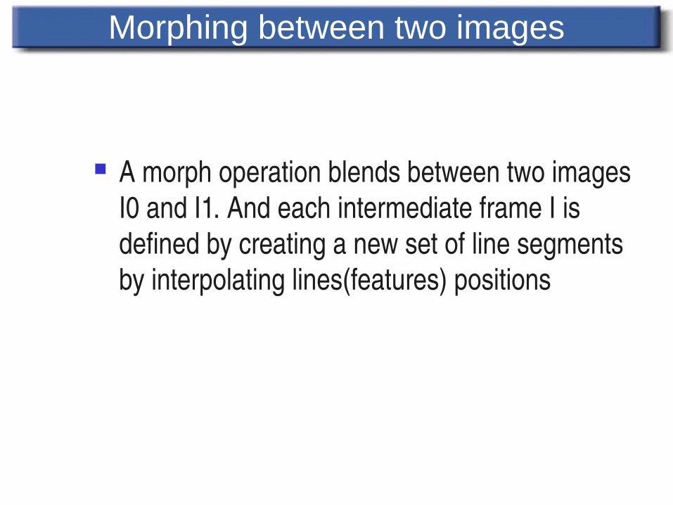
A morph operation blends between two images I0 and I1. And each intermediate frame I is defined by creating a new set of line segments by interpolating lines(features) positions
Morphing between two images
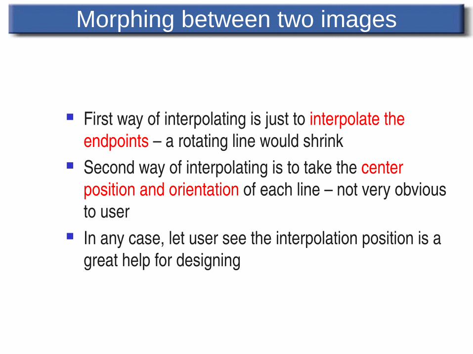
First way of interpolating is just to interpolate the endpoints – a rotating line would shrink
Second way of interpolating is to take the center position and orientation of each line – not very obvious to user
In any case, let user see the interpolation position is a great help for designing
Morphing between two images(cont’)
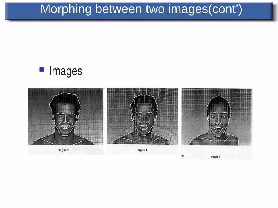
Images

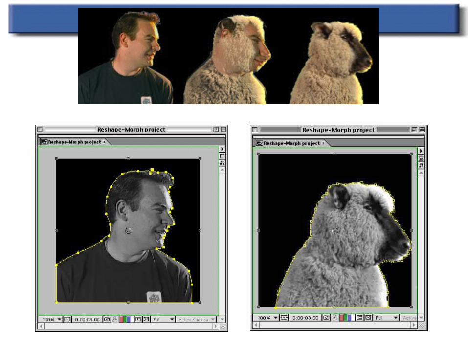
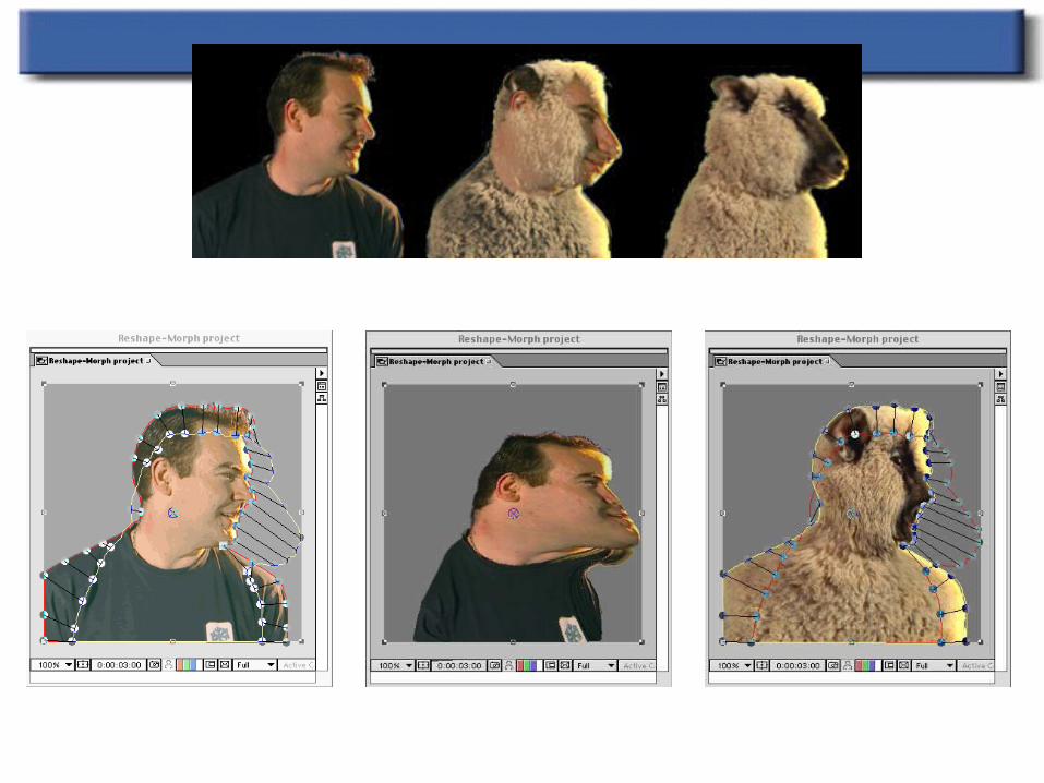
Beier & Neeley Example
Beier & Neeley Example
Advantages and Disadvantages
Advantages: Much more expressive To control features is very natural Disadvantages Speed Control “Ghostbusting” – to remove unexpected interpolation
generated pixels
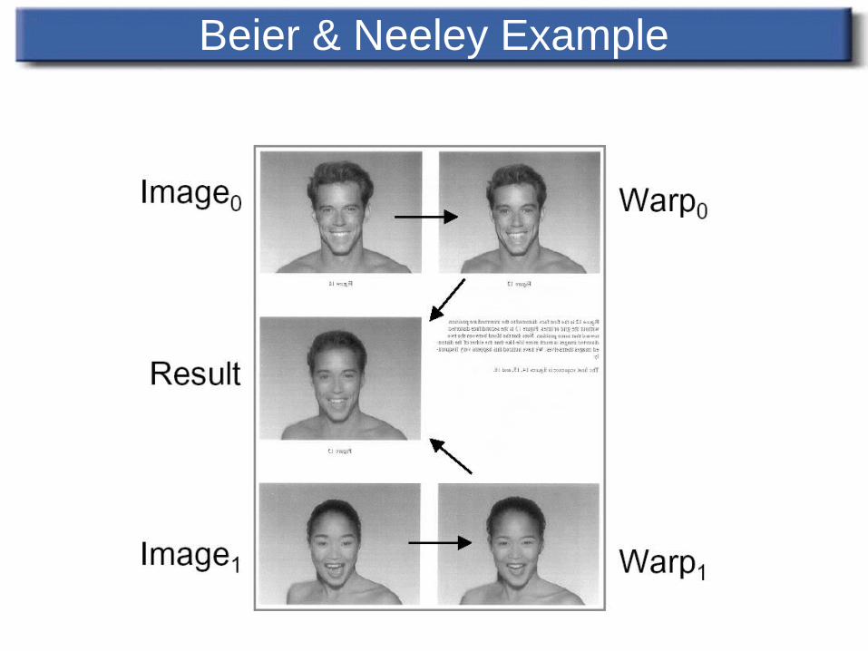
• Step I : Interpolating the lines: Interpolate the coordinates of the end points of every pair of lines.
• Step II : Warping the Images Each of the source images has to be deformed towards the
needed frame. The deformation works pixel by pixel is based on the reverse mapping. This algorithm is called Beier-Neely Algorithm.
Beier-Neely Algorithm
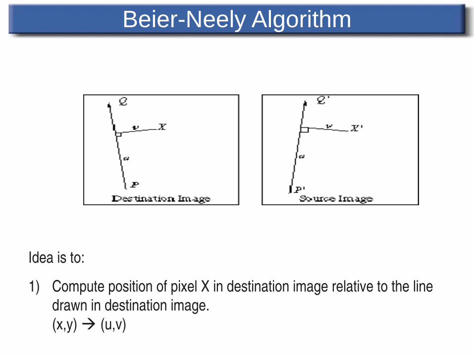
Idea is to:
1) Compute position of pixel X in destination image relative to the line drawn in destination image.(x,y) (u,v)
Beier-Neely Algorithm
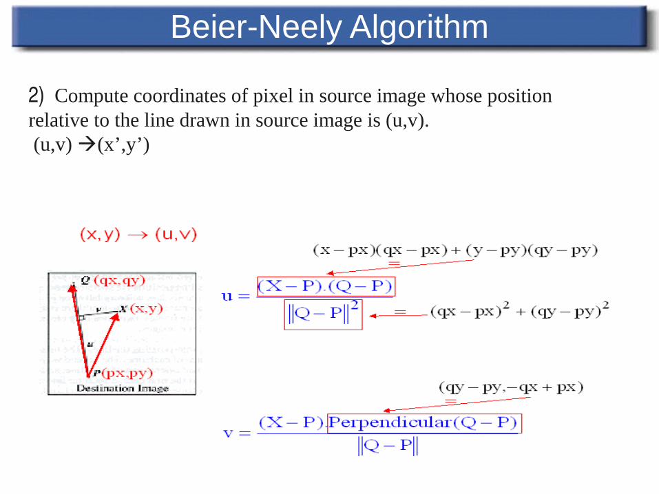
2) Compute coordinates of pixel in source image whose position relative to the line drawn in source image is (u,v). (u,v) (x’,y’)
Beier-Neely Algorithm
Beier-Neely Algorithm
Beier-Neely Algorithm
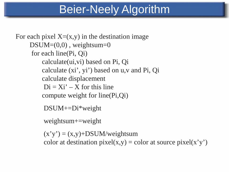
For each pixel X=(x,y) in the destination image DSUM=(0,0) , weightsum=0 for each line(Pi, Qi) calculate(ui,vi) based on Pi, Qi calculate (xi’, yi’) based on u,v and Pi, Qi calculate displacement Di = Xi’ – X for this line compute weight for line(Pi,Qi)
DSUM+=Di*weight
weightsum+=weight
(x’y’) = (x,y)+DSUM/weightsum color at destination pixel(x,y) = color at source pixel(x’y’)
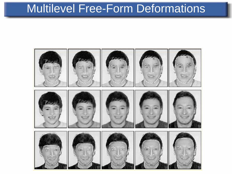
Multilevel Free-Form Deformations
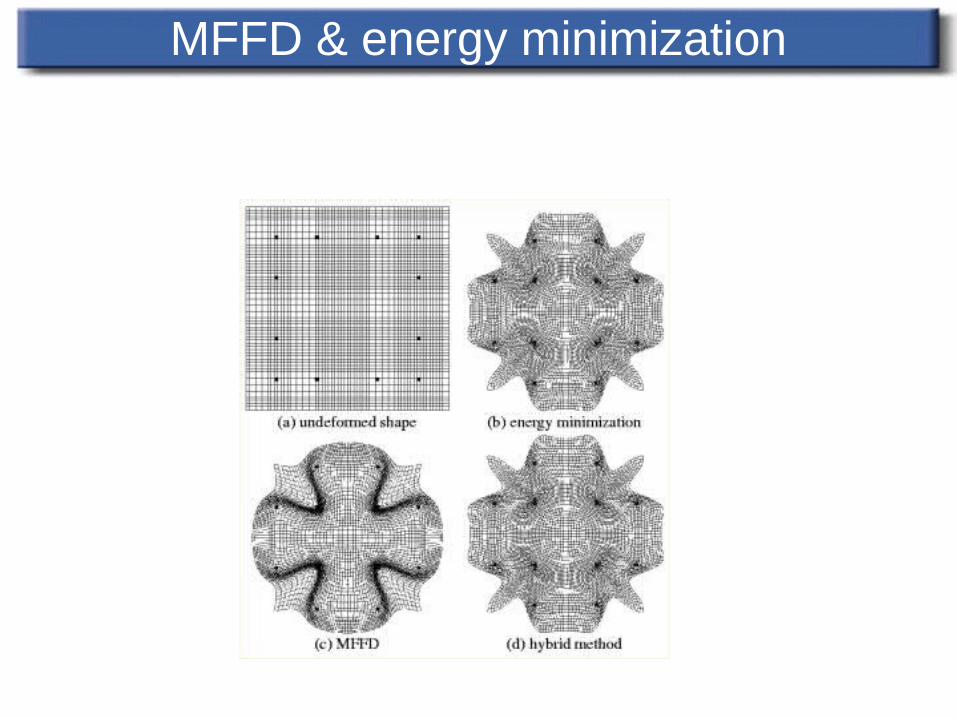
MFFD & energy minimization
Transition Control
Uniform vs. nonuniform metamorphosis Accelerated transition for some features but not
all may improve the results dramatically
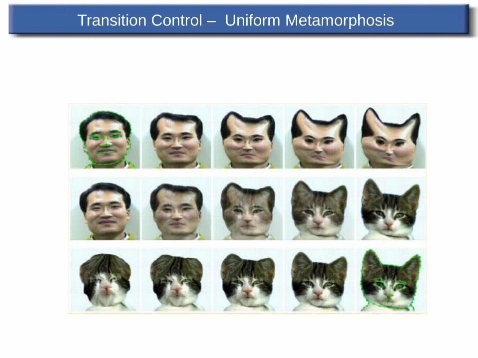
Transition Control – Uniform Metamorphosis
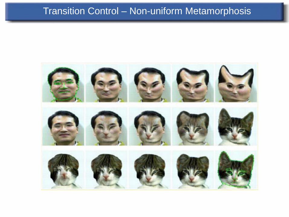
Transition Control – Non-uniform Metamorphosis
Animated Sequences
Morphing two sequences of live action, rather than just two still images
Mark all features in key frames Interpolate the features between key frames Do image metamorphosis on set of pair of
images… (Black & White video)
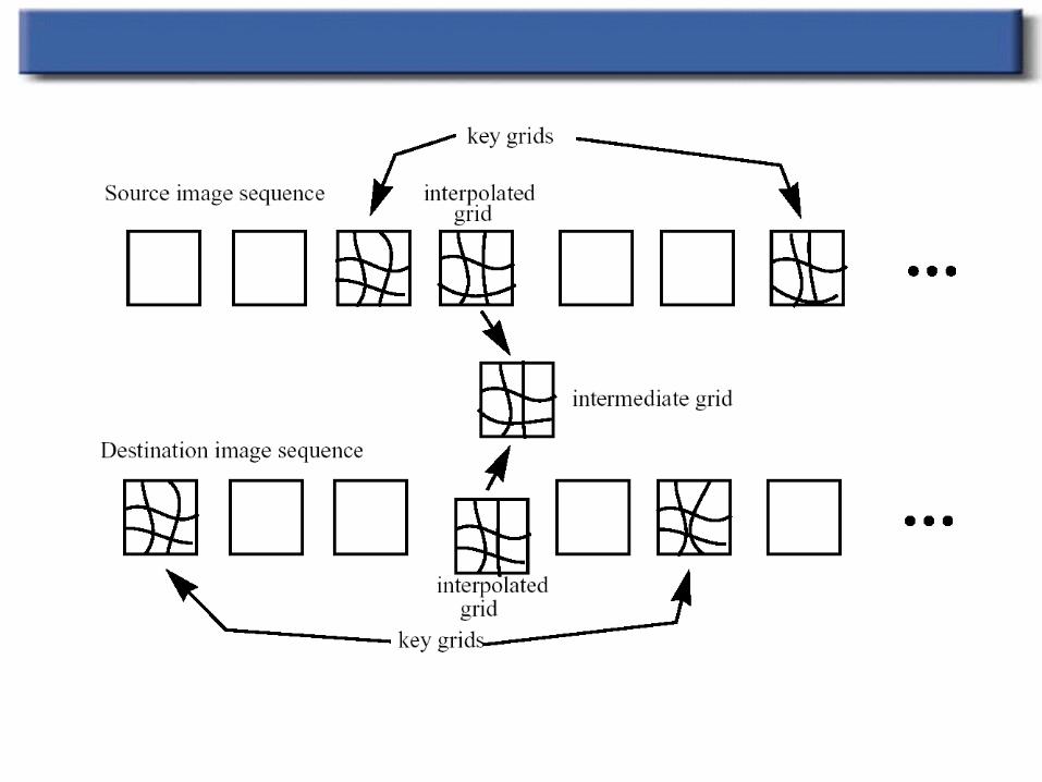
Image Morphing
Morphing for animated sequences: Define grids on key frames Grids for intermediate frames are created
Simple x,y interpolation of intersection points Image morphing performed framebyframe
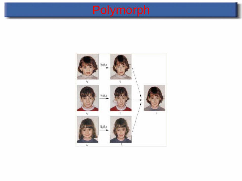
Polymorph
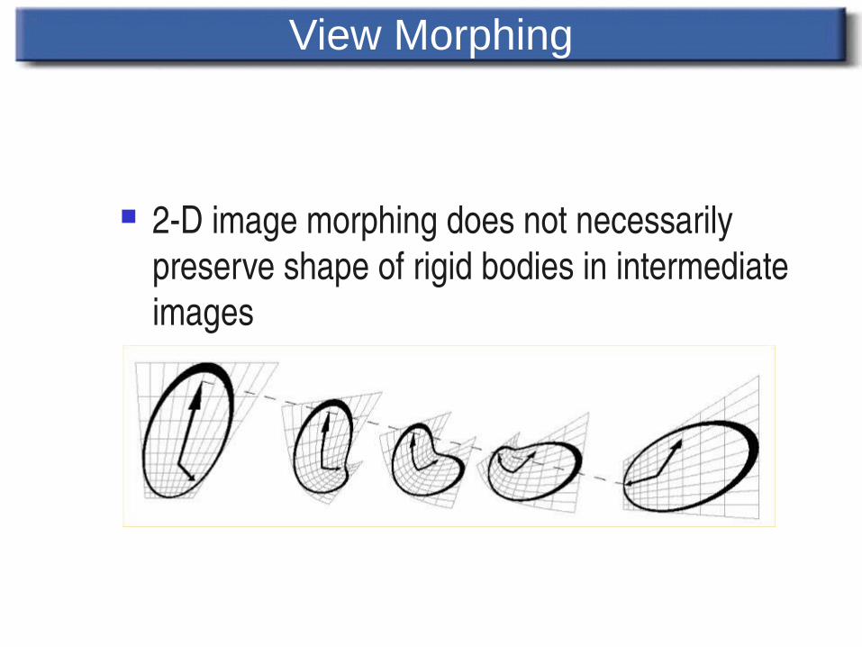
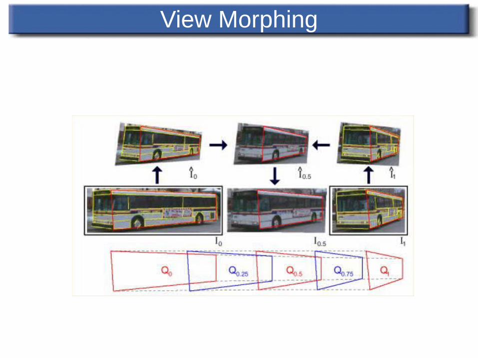
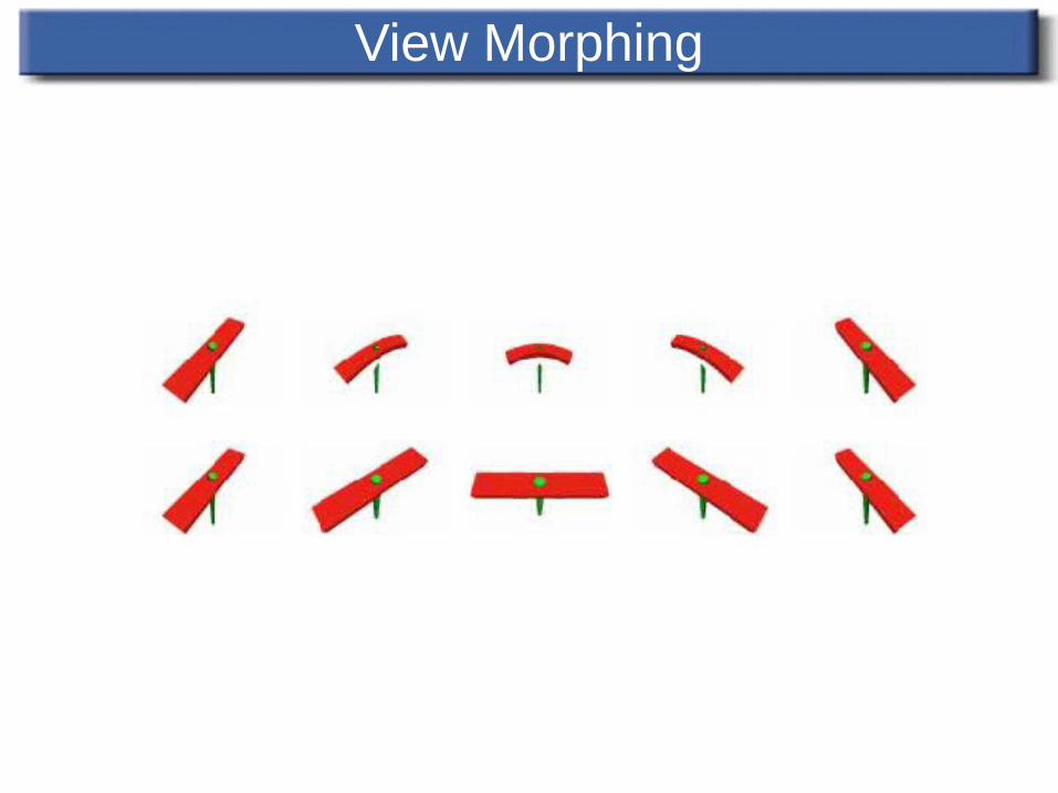
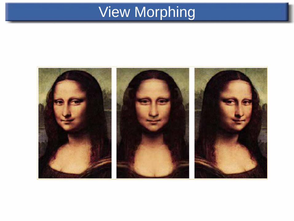
View Morphing
2D image morphing does not necessarily preserve shape of rigid bodies in intermediate images
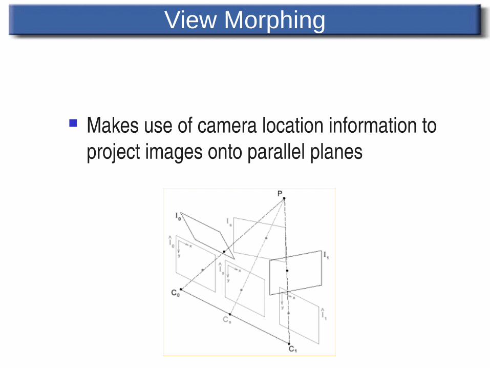
View Morphing
Makes use of camera location information to project images onto parallel planes
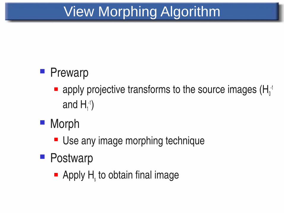
View Morphing Algorithm
Prewarp apply projective transforms to the source images (H0
1 and H1
1) Morph
Use any image morphing technique Postwarp
Apply Hs to obtain final image
View Morphing
View Morphing
View Morphing

MORPHING EXAMPLES
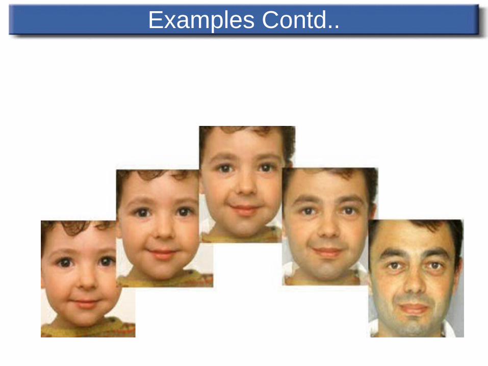
Examples Contd..