Embed Size (px)
Citation preview
2D Sketch
Contents 2D Sketch ......................................................................................................................................................................................................... 1
1.1 2D Sketch Introduction ................................................................................................................................................. 1
1.1.1 2D Sketch .................................................................................................................................................................. 1
1.1.2 Basic Setting of 2D Sketch .................................................................................................................................. 2
1.1.3 Exit 2D Sketch ......................................................................................................................................................... 4
1.2 Draw Common Geometry ............................................................................................................................................ 5
2.2.1 Points .......................................................................................................................................................................... 5
2.2.2 Lines and Construction Lines ........................................................................................................................... 8
2.2.3 Circles, Arcs and Ellipses ..................................................................................................................................12
2.2.4 Rectangle and Polygon .......................................................................................................................................15
2.2.5 Splines ......................................................................................................................................................................16
2.2.6 Equation Curves ...................................................................................................................................................19
2.2.7 Continuous Curves ..............................................................................................................................................20
2.2.10 Text ............................................................................................................................................................................23
2.2.11 Ready Sketch .........................................................................................................................................................25
1.3 Edit Curves .......................................................................................................................................................................25
1.3.1 Fillet...........................................................................................................................................................................26
1.3.2 Chamfer ...................................................................................................................................................................27
1.3.3 Trim...........................................................................................................................................................................28
1.3.4 Edit Splines ............................................................................................................................................................33
1.4 Edit the Sketch ...............................................................................................................................................................34
1.4.1 Pattern .....................................................................................................................................................................34
1.4.2 Move /Copy/ Rotate ...........................................................................................................................................36
1.4.3 Mirror .......................................................................................................................................................................38
1.4.4 Scale/Stretch/Drag ..............................................................................................................................................39
1.5 Constraints .......................................................................................................................................................................42
1.5.1 Setting of Constraint Status ..............................................................................................................................42
1.5.2 Add Constraints .....................................................................................................................................................43
1.5.3 Inquire Constraints and Constraint Status .................................................................................................47
1.6 Dimensions ......................................................................................................................................................................48
1.6.1 Set Dimension Attribute ...................................................................................................................................48
1.6.2 Quick Dimension .................................................................................................................................................49
1.6.3 Add Linear Dimension .......................................................................................................................................49
1.6.4 Add Linear Offset Dimension..........................................................................................................................51
1.6.5 Angular Dimension .............................................................................................................................................52
1.6.6 Add Radial/Diametric Dimension .................................................................................................................53
1.6.7 Add Arc Length Dimension ..............................................................................................................................54
1.6.8 Modify Dimension Value ...................................................................................................................................55
1.7 Check the Sketch ...........................................................................................................................................................58
1.7.1 Curve Connectivity ..............................................................................................................................................58
1.7.2 Check Overlap .......................................................................................................................................................58
1.7.3 Curvature plot .......................................................................................................................................................59
1.8 Cases---2D Sketch .........................................................................................................................................................60
1.8.1 General Process of Drawing 2D Sketch ......................................................................................................60
1.8.2 Case1 ........................................................................................................................................................................61
1.8.3 Case2 ........................................................................................................................................................................65
1.9 Exercises ...........................................................................................................................................................................69
1
2D Sketch
Key Points:
Draw common 2D sketch geometry
Edit 2D sketch geometry
Add reasonable constraints for 2D sketch
Check the 2D sketch
1.1 2D Sketch Introduction
2D sketch is the basis for modeling. Most of models are begin with the sketch. 2D sketch
module includes drawing tools of 2D sketch, editing features, constraints & dimensions tools,
and inspection functionality. In ZW3D, sketch is the independent environment.
1.1.1 2D Sketch
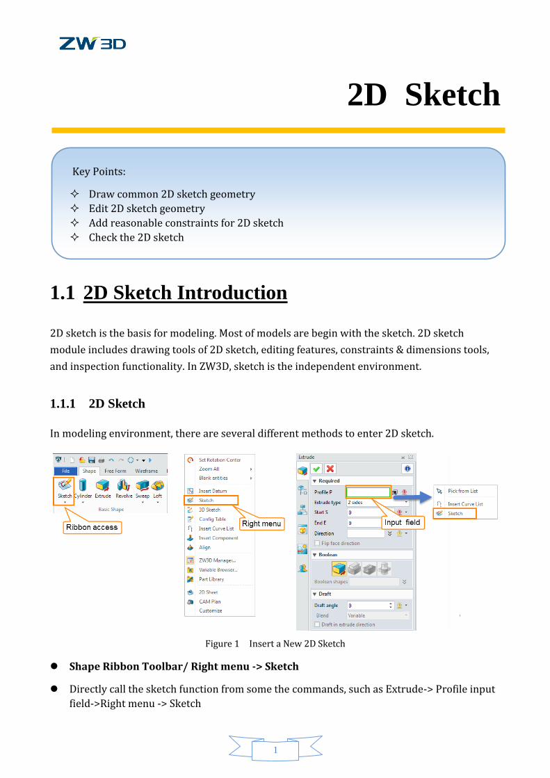
In modeling environment, there are several different methods to enter 2D sketch.
Figure 1 Insert a New 2D Sketch
Shape Ribbon Toolbar/ Right menu -> Sketch
Directly call the sketch function from some the commands, such as Extrude-> Profile input
field->Right menu -> Sketch
2
2D Sketch
2D Sketch plane could be datum plane, such as XY, XZ, YZ or a part face.
In ZW3D, the default 2D sketch plane is XY datum plane.
1.1.2 Basic Setting of 2D Sketch
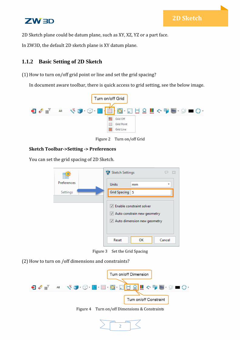
(1) How to turn on/off grid point or line and set the grid spacing?
In document aware toolbar, there is quick access to grid setting, see the below image.
Figure 2 Turn on/off Grid
Sketch Toolbar->Setting -> Preferences
You can set the grid spacing of 2D Sketch.
Figure 3 Set the Grid Spacing
(2) How to turn on /off dimensions and constraints?
Figure 4 Turn on/off Dimensions & Constraints
3
2D Sketch
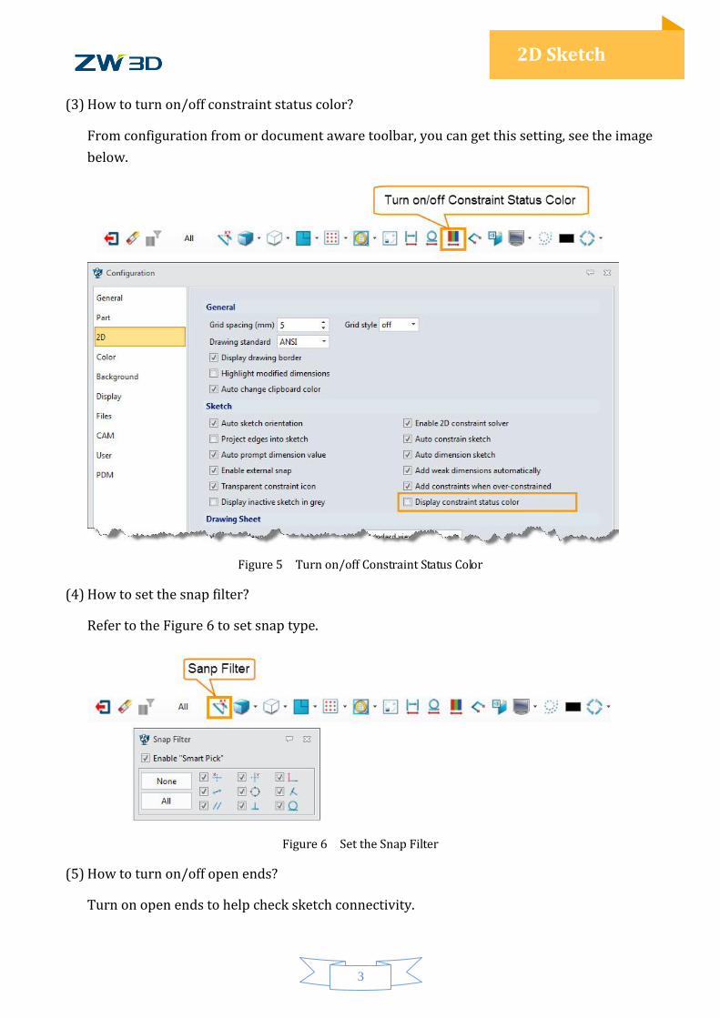
(3) How to turn on/off constraint status color?
From configuration from or document aware toolbar, you can get this setting, see the image
below.
Figure 5 Turn on/off Constraint Status Color
(4) How to set the snap filter?
Refer to the Figure 6 to set snap type.
Figure 6 Set the Snap Filter
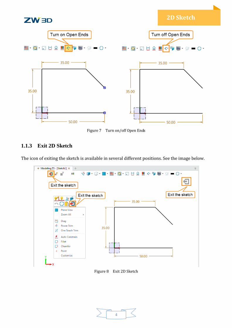
(5) How to turn on/off open ends?
Turn on open ends to help check sketch connectivity.
4
2D Sketch
Figure 7 Turn on/off Open Ends
1.1.3 Exit 2D Sketch
The icon of exiting the sketch is available in several different positions. See the image below.
Figure 8 Exit 2D Sketch
5
2D Sketch
1.2 Draw Common Geometry
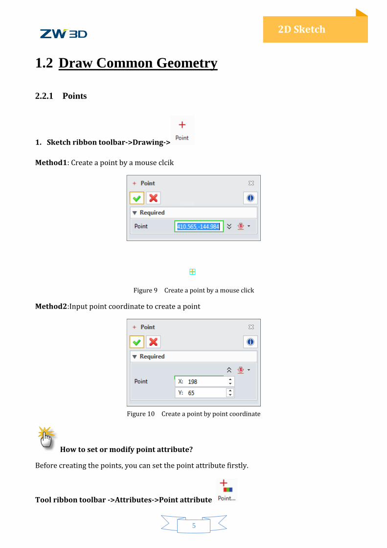
2.2.1 Points
1. Sketch ribbon toolbar->Drawing->
Method1: Create a point by a mouse clcik
Figure 9 Create a point by a mouse click
Method2:Input point coordinate to create a point
Figure 10 Create a point by point coordinate
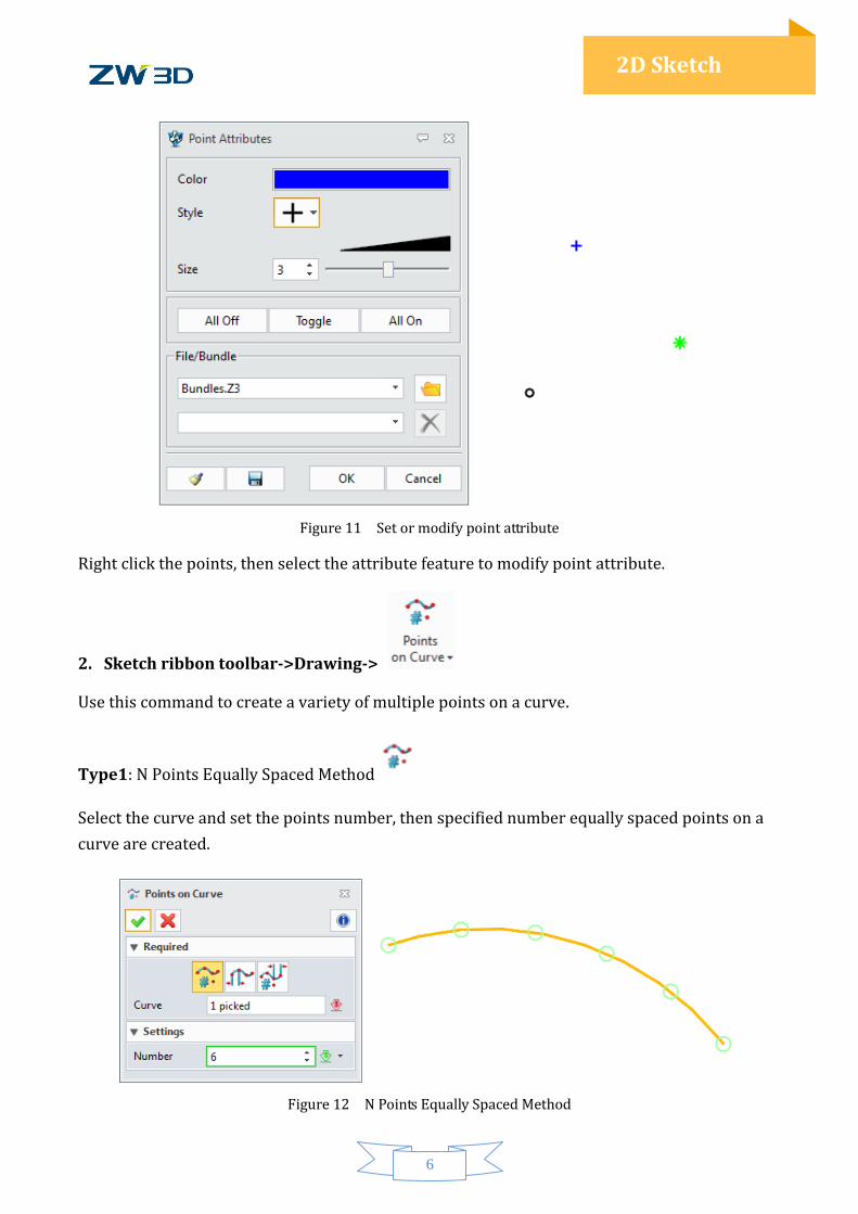
How to set or modify point attribute?
Before creating the points, you can set the point attribute firstly.
Tool ribbon toolbar ->Attributes->Point attribute
6
2D Sketch
Figure 11 Set or modify point attribute
Right click the points, then select the attribute feature to modify point attribute.
2. Sketch ribbon toolbar->Drawing->
Use this command to create a variety of multiple points on a curve.
Type1: N Points Equally Spaced Method
Select the curve and set the points number, then specified number equally spaced points on a
curve are created.
Figure 12 N Points Equally Spaced Method
7
2D Sketch
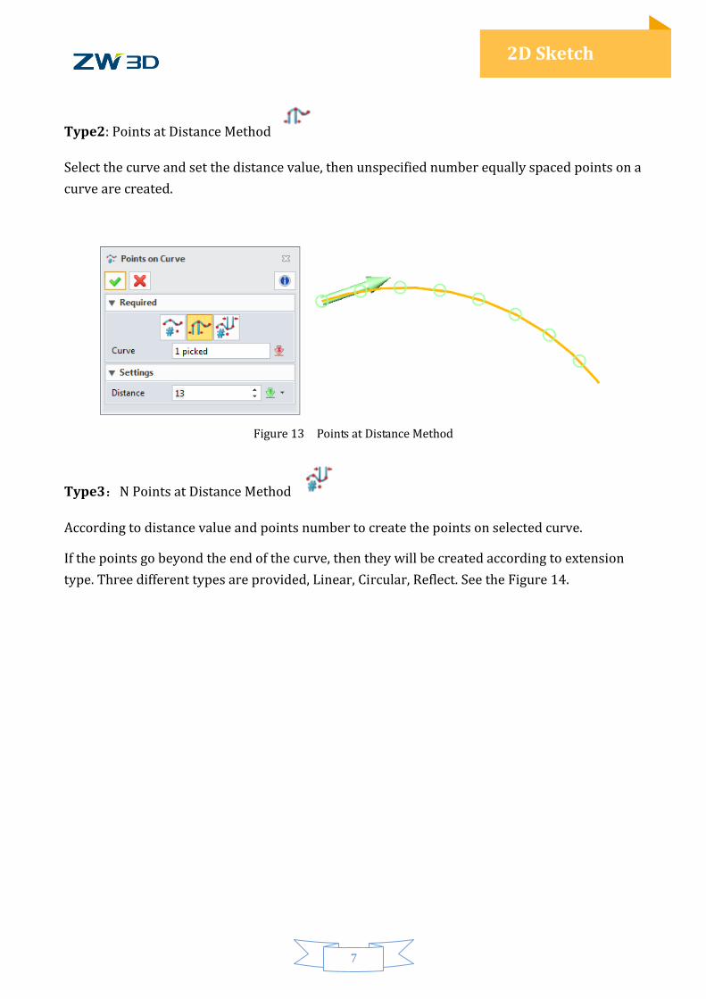
Type2: Points at Distance Method
Select the curve and set the distance value, then unspecified number equally spaced points on a
curve are created.
Figure 13 Points at Distance Method
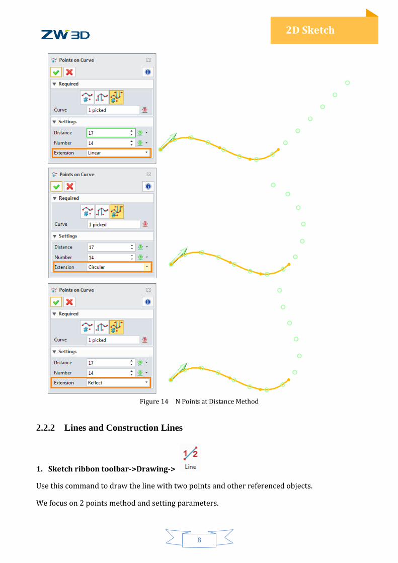
Type3:N Points at Distance Method
According to distance value and points number to create the points on selected curve.
If the points go beyond the end of the curve, then they will be created according to extension
type. Three different types are provided, Linear, Circular, Reflect. See the Figure 14.
8
2D Sketch
Figure 14 N Points at Distance Method
2.2.2 Lines and Construction Lines
1. Sketch ribbon toolbar->Drawing->
Use this command to draw the line with two points and other referenced objects.
We focus on 2 points method and setting parameters.
9
2D Sketch
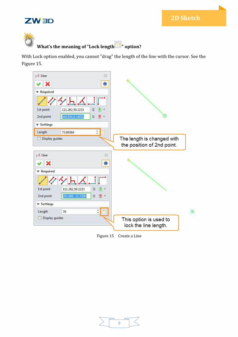
What’s the meaning of “Lock length ” option?
With Lock option enabled, you cannot "drag" the length of the line with the cursor. See the
Figure 15.
Figure 15 Create a Line
10
2D Sketch
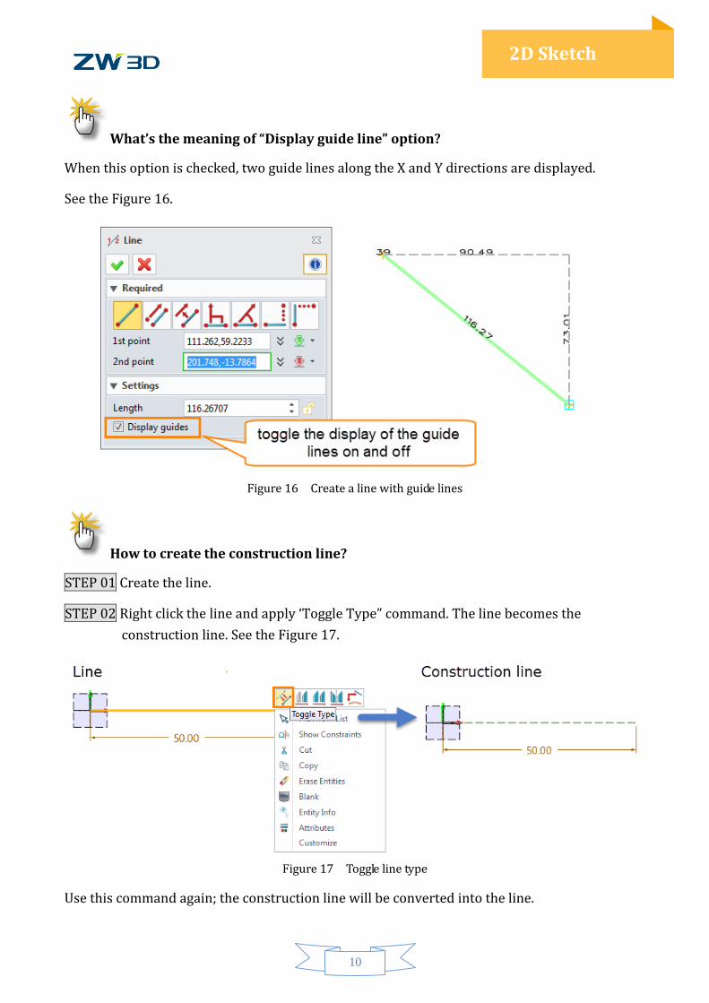
What’s the meaning of “Display guide line” option?
When this option is checked, two guide lines along the X and Y directions are displayed.
See the Figure 16.
Figure 16 Create a line with guide lines
How to create the construction line?
STEP 01 Create the line.
STEP 02 Right click the line and apply ‘Toggle Type” command. The line becomes the
construction line. See the Figure 17.
Figure 17 Toggle line type
Use this command again; the construction line will be converted into the line.
11
2D Sketch
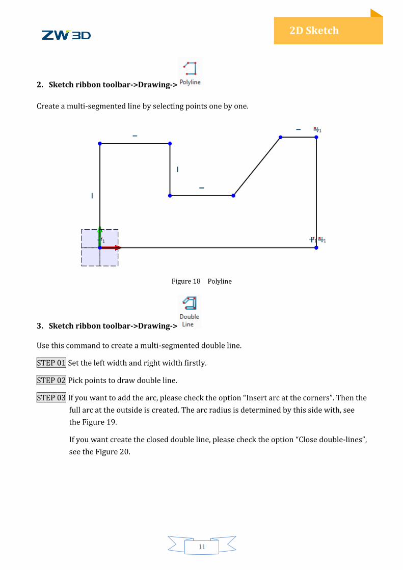
2. Sketch ribbon toolbar->Drawing->
Create a multi-segmented line by selecting points one by one.
Figure 18 Polyline
3. Sketch ribbon toolbar->Drawing->
Use this command to create a multi-segmented double line.
STEP 01 Set the left width and right width firstly.
STEP 02 Pick points to draw double line.
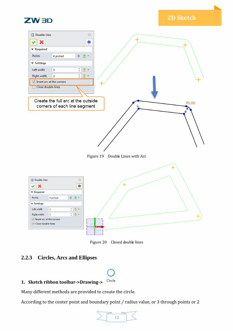
STEP 03 If you want to add the arc, please check the option “Insert arc at the corners”. Then the
full arc at the outside is created. The arc radius is determined by this side with, see
the Figure 19.
If you want create the closed double line, please check the option “Close double-lines”,
see the Figure 20.
12
2D Sketch
Figure 19 Double Lines with Arc
Figure 20 Closed double lines
2.2.3 Circles, Arcs and Ellipses
1. Sketch ribbon toolbar->Drawing->
Many different methods are provided to create the circle.
According to the center point and boundary point / radius value, or 3 through points or 2
13
2D Sketch
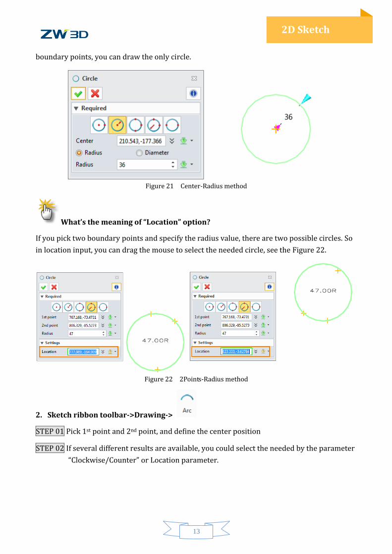
boundary points, you can draw the only circle.
Figure 21 Center-Radius method
What’s the meaning of “Location” option?
If you pick two boundary points and specify the radius value, there are two possible circles. So
in location input, you can drag the mouse to select the needed circle, see the Figure 22.
Figure 22 2Points-Radius method
2. Sketch ribbon toolbar->Drawing->
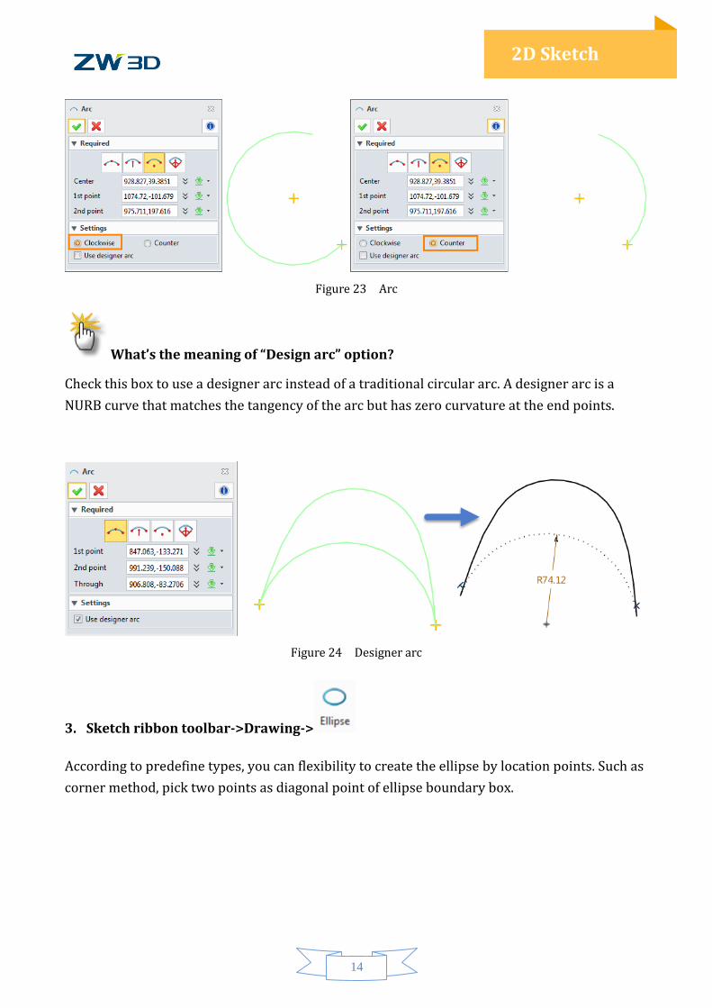
STEP 01 Pick 1st point and 2nd point, and define the center position
STEP 02 If several different results are available, you could select the needed by the parameter
“Clockwise/Counter” or Location parameter.
14
2D Sketch
Figure 23 Arc
What’s the meaning of “Design arc” option?
Check this box to use a designer arc instead of a traditional circular arc. A designer arc is a
NURB curve that matches the tangency of the arc but has zero curvature at the end points.
Figure 24 Designer arc
3. Sketch ribbon toolbar->Drawing->
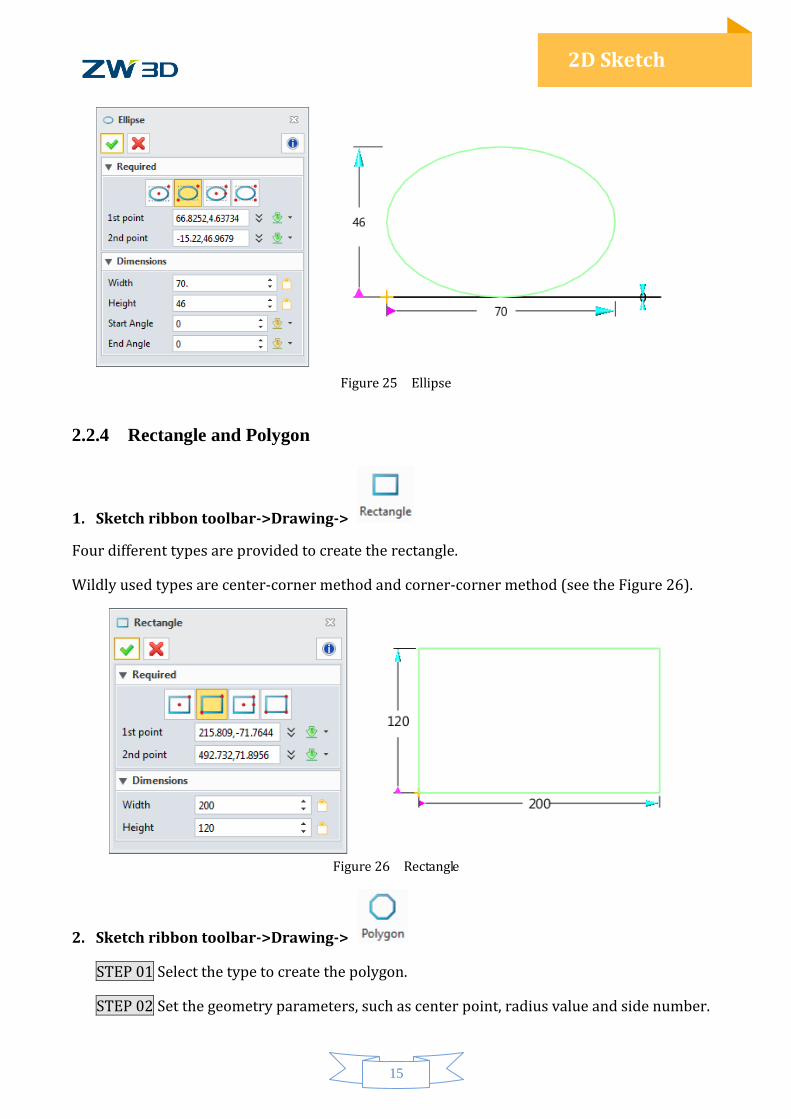
According to predefine types, you can flexibility to create the ellipse by location points. Such as
corner method, pick two points as diagonal point of ellipse boundary box.
15
2D Sketch
Figure 25 Ellipse
2.2.4 Rectangle and Polygon
1. Sketch ribbon toolbar->Drawing->
Four different types are provided to create the rectangle.
Wildly used types are center-corner method and corner-corner method (see the Figure 26).
Figure 26 Rectangle
2. Sketch ribbon toolbar->Drawing->
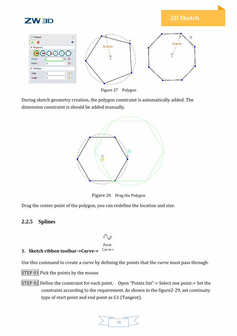
STEP 01 Select the type to create the polygon.
STEP 02 Set the geometry parameters, such as center point, radius value and side number.
16
2D Sketch
Figure 27 Polygon
During sketch geometry creation, the polygon constraint is automatically added. The
dimension constraint is should be added manually.
Figure 28 Drag the Polygon
Drag the center point of the polygon, you can redefine the location and size.
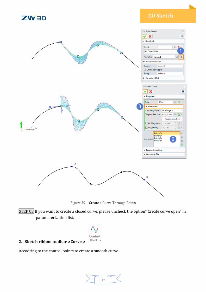
2.2.5 Splines
1. Sketch ribbon toolbar->Curve->
Use this command to create a curve by defining the points that the curve must pass through.
STEP 01 Pick the points by the mouse
STEP 02 Define the constraint for each point. Open “Points list”-> Select one point-> Set the
constraint according to the requirement. As shown in the figure2-29, set continuity
type of start point and end point as G1 (Tangent).
17
2D Sketch
Figure 29 Create a Curve Through Points
STEP 03 If you want to create a closed curve, please uncheck the option” Create curve open” in
parameterization list.
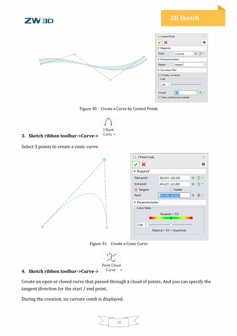
2. Sketch ribbon toolbar->Curve->
Accodring to the control points to create a smooth curve.
18
2D Sketch
Figure 30 Create a Curve by Control Points
3. Sketch ribbon toolbar->Curve->
Select 3 points to create a conic curve.
Figure 31 Create a Conic Curve
4. Sketch ribbon toolbar->Curve->
Create an open or closed curve that passed through a cloud of points. And you can specify the
tangent direction for the start / end point.
During the creation, no curvate comb is displayed.
19
2D Sketch
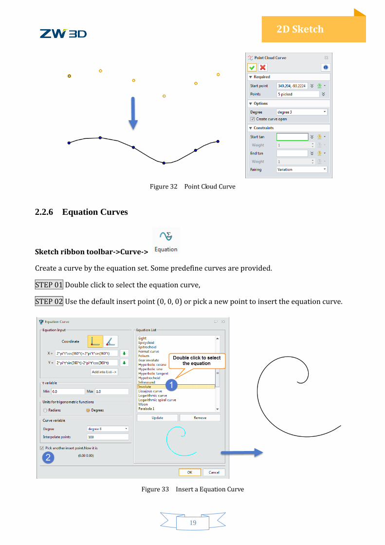
Figure 32 Point Cloud Curve
2.2.6 Equation Curves
Sketch ribbon toolbar->Curve->
Create a curve by the equation set. Some predefine curves are provided.
STEP 01 Double click to select the equation curve,
STEP 02 Use the default insert point (0, 0, 0) or pick a new point to insert the equation curve.
Figure 33 Insert a Equation Curve
20
2D Sketch
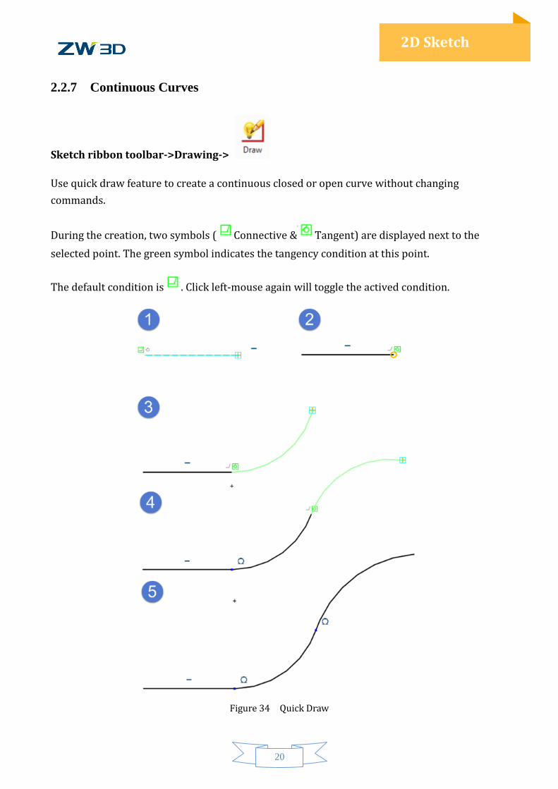
2.2.7 Continuous Curves
Sketch ribbon toolbar->Drawing->
Use quick draw feature to create a continuous closed or open curve without changing
commands.
During the creation, two symbols ( Connective & Tangent) are displayed next to the
selected point. The green symbol indicates the tangency condition at this point.
The default condition is . Click left-mouse again will toggle the actived condition.
Figure 34 Quick Draw
21
2D Sketch
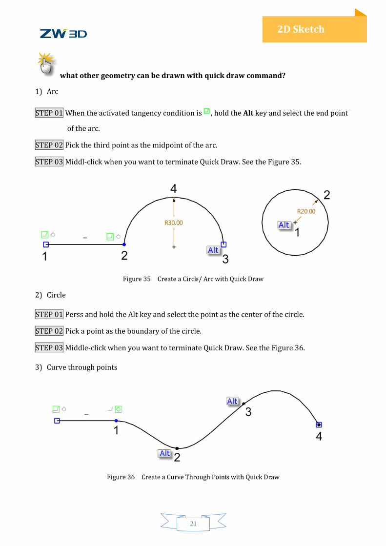
what other geometry can be drawn with quick draw command?
1) Arc
STEP 01 When the activated tangency condition is , hold the Alt key and select the end point
of the arc.
STEP 02 Pick the third point as the midpoint of the arc.
STEP 03 Middl-click when you want to terminate Quick Draw. See the Figure 35.
Figure 35 Create a Circle/ Arc with Quick Draw
2) Circle
STEP 01 Perss and hold the Alt key and select the point as the center of the circle.
STEP 02 Pick a point as the boundary of the circle.
STEP 03 Middle-click when you want to terminate Quick Draw. See the Figure 36.
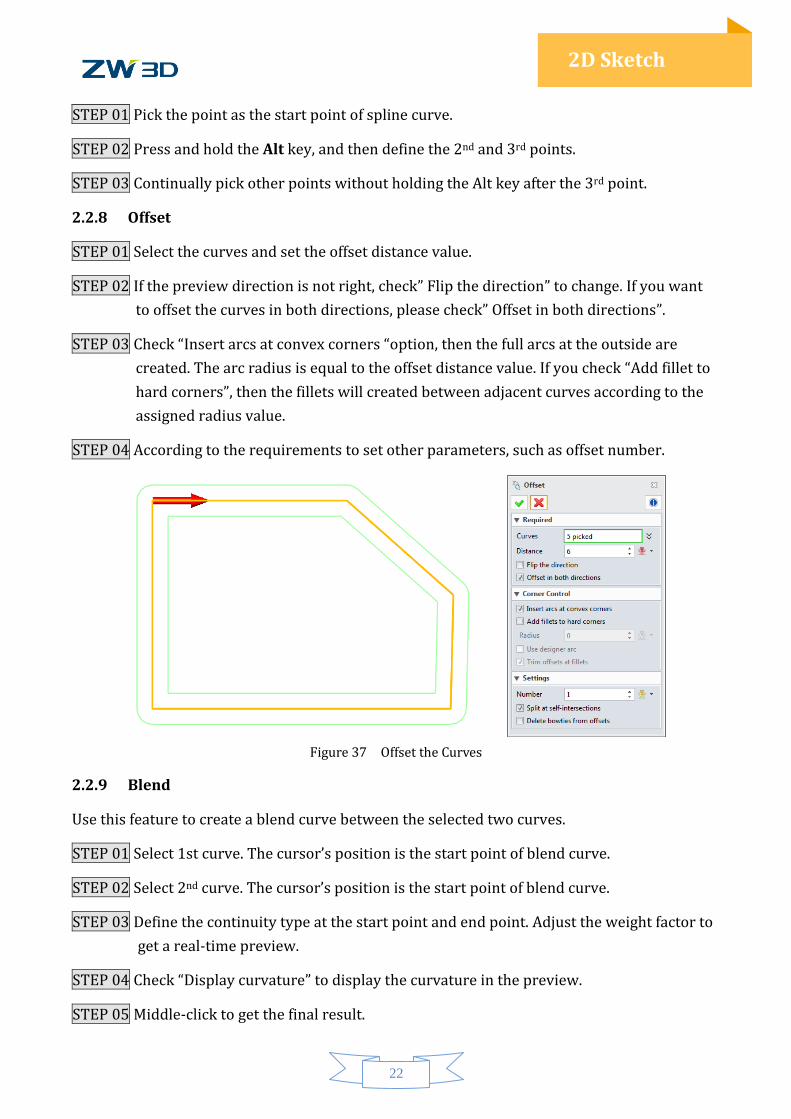
3) Curve through points
Figure 36 Create a Curve Through Points with Quick Draw
22
2D Sketch
STEP 01 Pick the point as the start point of spline curve.
STEP 02 Press and hold the Alt key, and then define the 2nd and 3rd points.
STEP 03 Continually pick other points without holding the Alt key after the 3rd point.
2.2.8 Offset
STEP 01 Select the curves and set the offset distance value.
STEP 02 If the preview direction is not right, check” Flip the direction” to change. If you want
to offset the curves in both directions, please check” Offset in both directions”.
STEP 03 Check “Insert arcs at convex corners “option, then the full arcs at the outside are
created. The arc radius is equal to the offset distance value. If you check “Add fillet to
hard corners”, then the fillets will created between adjacent curves according to the
assigned radius value.
STEP 04 According to the requirements to set other parameters, such as offset number.
Figure 37 Offset the Curves
2.2.9 Blend
Use this feature to create a blend curve between the selected two curves.
STEP 01 Select 1st curve. The cursor’s position is the start point of blend curve.
STEP 02 Select 2nd curve. The cursor’s position is the start point of blend curve.
STEP 03 Define the continuity type at the start point and end point. Adjust the weight factor to
get a real-time preview.
STEP 04 Check “Display curvature” to display the curvature in the preview.
STEP 05 Middle-click to get the final result.
23
2D Sketch
Figure 38 Blend curve
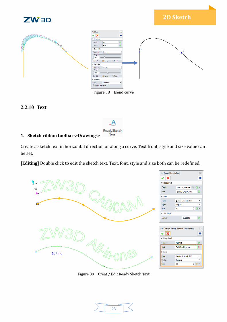
2.2.10 Text
1. Sketch ribbon toolbar->Drawing->
Create a sketch text in horizontal direction or along a curve. Text front, style and size value can
be set.
[Editing] Double click to edit the sketch text. Text, font, style and size both can be redefined.
Figure 39 Creat / Edit Ready Sketch Text
24
2D Sketch
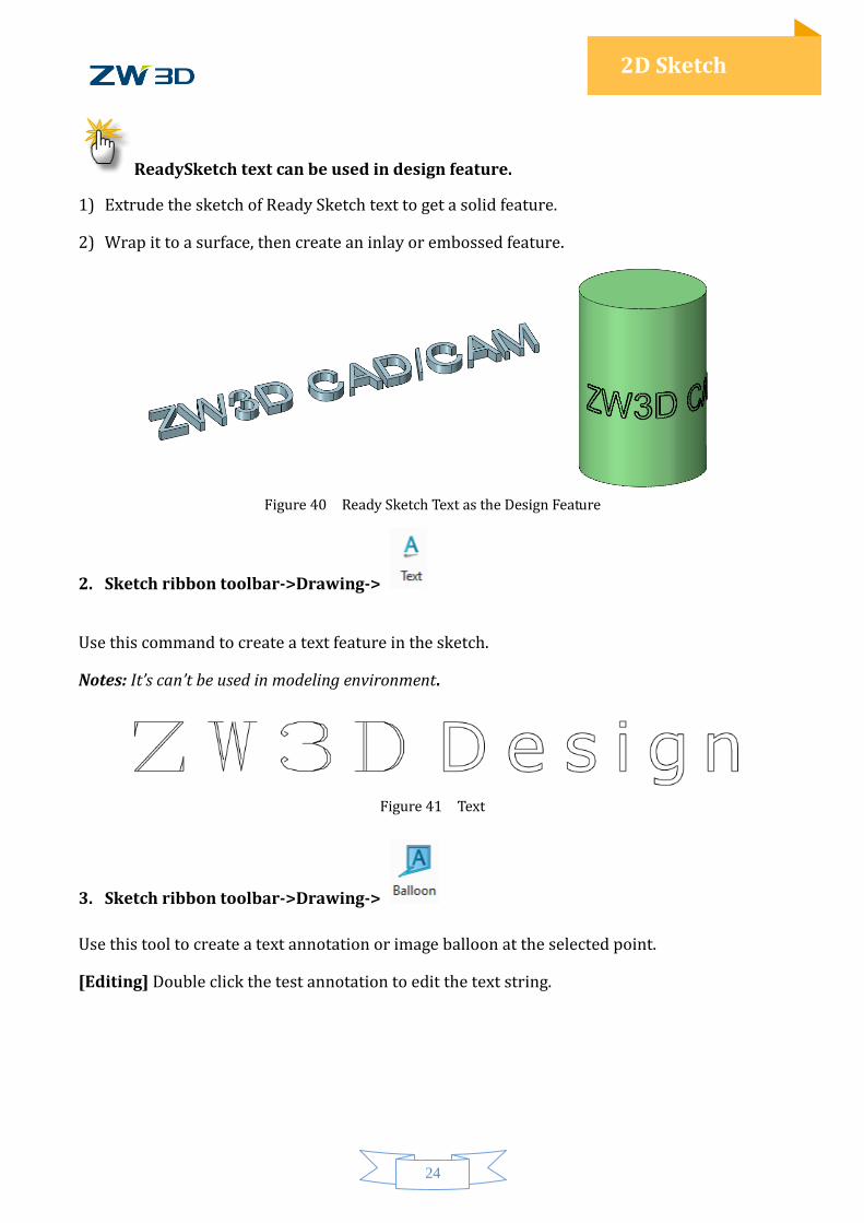
ReadySketch text can be used in design feature.
1) Extrude the sketch of Ready Sketch text to get a solid feature.
2) Wrap it to a surface, then create an inlay or embossed feature.
Figure 40 Ready Sketch Text as the Design Feature
2. Sketch ribbon toolbar->Drawing->
Use this command to create a text feature in the sketch.
Notes: It’s can’t be used in modeling environment.
Figure 41 Text
3. Sketch ribbon toolbar->Drawing->
Use this tool to create a text annotation or image balloon at the selected point.
[Editing] Double click the test annotation to edit the text string.
25
2D Sketch
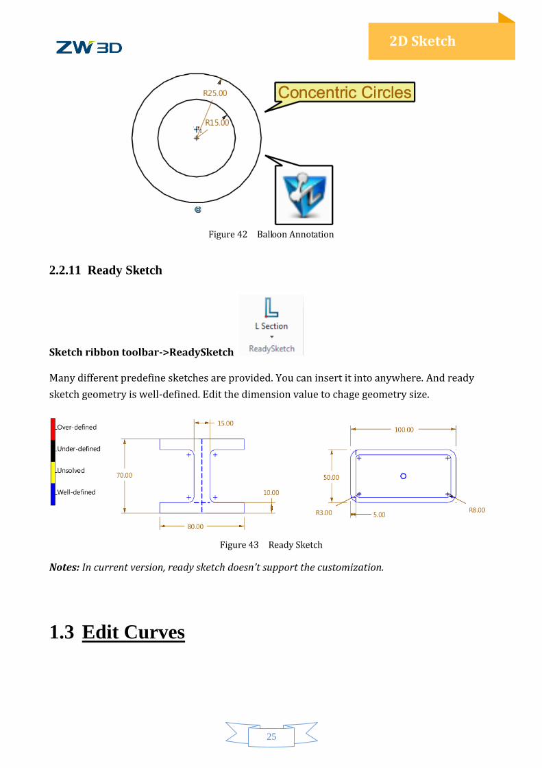
Figure 42 Balloon Annotation
2.2.11 Ready Sketch
Sketch ribbon toolbar->ReadySketch
Many different predefine sketches are provided. You can insert it into anywhere. And ready
sketch geometry is well-defined. Edit the dimension value to chage geometry size.
Figure 43 Ready Sketch
Notes: In current version, ready sketch doesn’t support the customization.
1.3 Edit Curves
26
2D Sketch
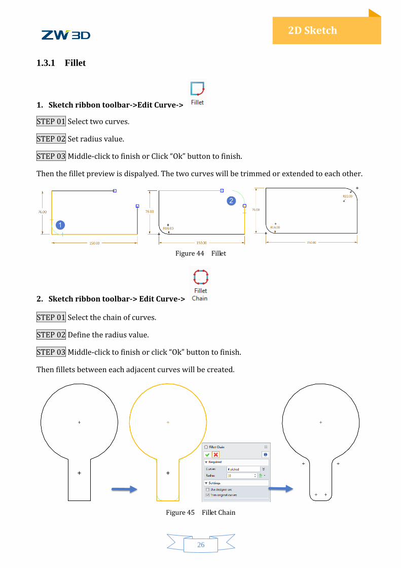
1.3.1 Fillet
1. Sketch ribbon toolbar->Edit Curve->
STEP 01 Select two curves.
STEP 02 Set radius value.
STEP 03 Middle-click to finish or Click “Ok” button to finish.
Then the fillet preview is dispalyed. The two curves will be trimmed or extended to each other.
Figure 44 Fillet
2. Sketch ribbon toolbar-> Edit Curve->
STEP 01 Select the chain of curves.
STEP 02 Define the radius value.
STEP 03 Middle-click to finish or click “Ok” button to finish.
Then fillets between each adjacent curves will be created.
Figure 45 Fillet Chain
27
2D Sketch
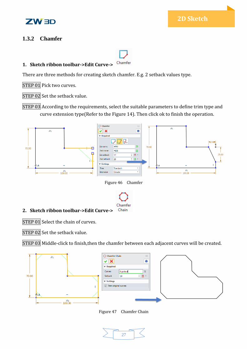
1.3.2 Chamfer
1. Sketch ribbon toolbar->Edit Curve->
There are three methods for creating sketch chamfer. E.g. 2 setback values type.
STEP 01 Pick two curves.
STEP 02 Set the setback value.
STEP 03 According to the requirements, select the suitable parameters to define trim type and
curve extension type(Refer to the Figure 14). Then click ok to finish the operation.
Figure 46 Chamfer
2. Sketch ribbon toolbar->Edit Curve->
STEP 01 Select the chain of curves.
STEP 02 Set the setback value.
STEP 03 Middle-click to finish,then the chamfer between each adjacent curves will be created.
Figure 47 Chamfer Chain
28
2D Sketch
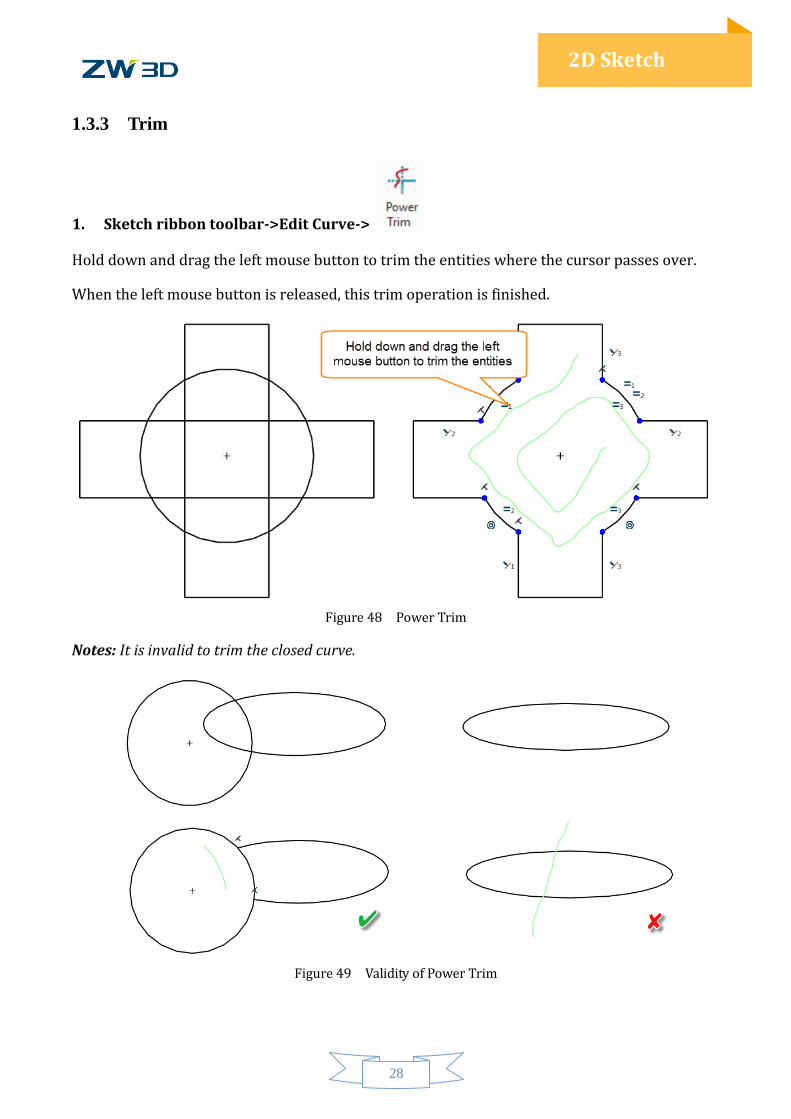
1.3.3 Trim
1. Sketch ribbon toolbar->Edit Curve->
Hold down and drag the left mouse button to trim the entities where the cursor passes over.
When the left mouse button is released, this trim operation is finished.
Figure 48 Power Trim
Notes: It is invalid to trim the closed curve.
Figure 49 Validity of Power Trim
29
2D Sketch
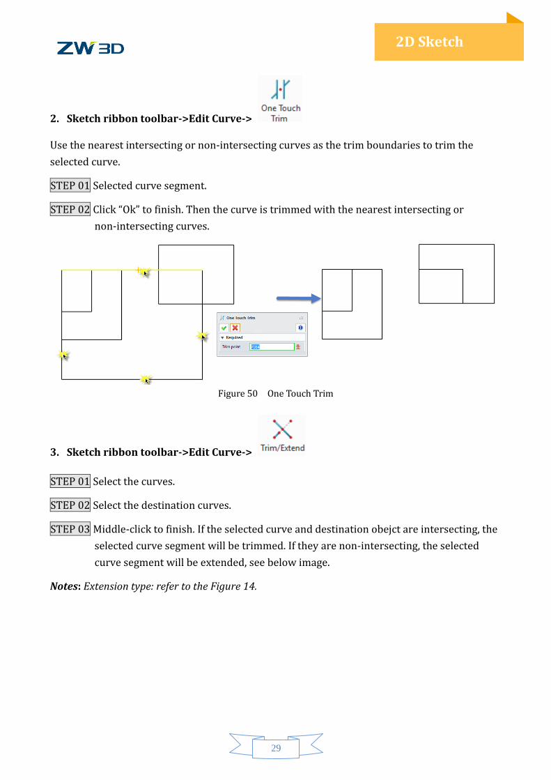
2. Sketch ribbon toolbar->Edit Curve->
Use the nearest intersecting or non-intersecting curves as the trim boundaries to trim the
selected curve.
STEP 01 Selected curve segment.
STEP 02 Click “Ok” to finish. Then the curve is trimmed with the nearest intersecting or
non-intersecting curves.
Figure 50 One Touch Trim
3. Sketch ribbon toolbar->Edit Curve->
STEP 01 Select the curves.
STEP 02 Select the destination curves.
STEP 03 Middle-click to finish. If the selected curve and destination obejct are intersecting, the
selected curve segment will be trimmed. If they are non-intersecting, the selected
curve segment will be extended, see below image.
Notes: Extension type: refer to the Figure 14.
30
2D Sketch
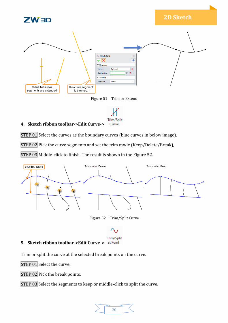
Figure 51 Trim or Extend
4. Sketch ribbon toolbar->Edit Curve->
STEP 01 Select the curves as the boundary curves (blue curves in below image).
STEP 02 Pick the curve segments and set the trim mode (Keep/Delete/Break),
STEP 03 Middle-click to finish. The result is shown in the Figure 52.
Figure 52 Trim/Split Curve
5. Sketch ribbon toolbar->Edit Curve->
Trim or split the curve at the selected break points on the curve.
STEP 01 Select the curve.
STEP 02 Pick the break points.
STEP 03 Select the segments to keep or middle-click to split the curve.
31
2D Sketch
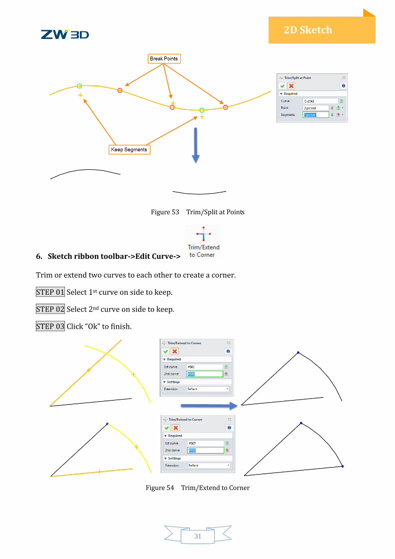
Figure 53 Trim/Split at Points
6. Sketch ribbon toolbar->Edit Curve->
Trim or extend two curves to each other to create a corner.
STEP 01 Select 1st curve on side to keep.
STEP 02 Select 2nd curve on side to keep.
STEP 03 Click “Ok” to finish.
Figure 54 Trim/Extend to Corner
32
2D Sketch
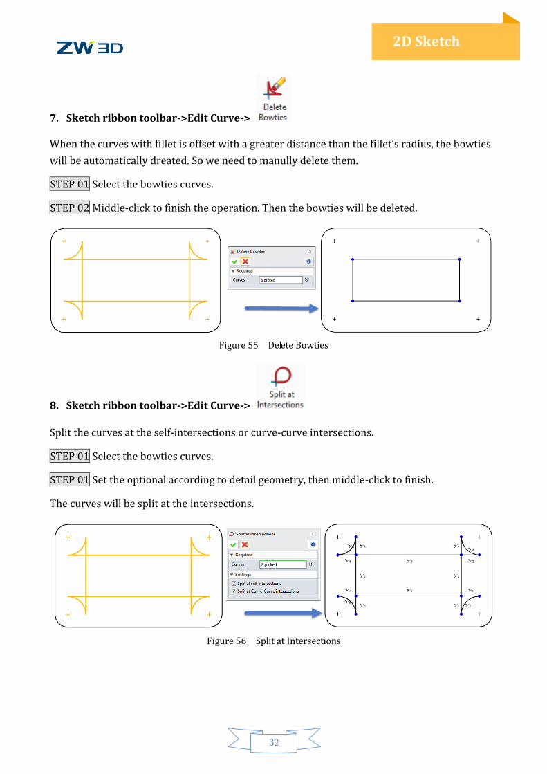
7. Sketch ribbon toolbar->Edit Curve->
When the curves with fillet is offset with a greater distance than the fillet’s radius, the bowties
will be automatically dreated. So we need to manully delete them.
STEP 01 Select the bowties curves.
STEP 02 Middle-click to finish the operation. Then the bowties will be deleted.
Figure 55 Delete Bowties
8. Sketch ribbon toolbar->Edit Curve->
Split the curves at the self-intersections or curve-curve intersections.
STEP 01 Select the bowties curves.
STEP 01 Set the optional according to detail geometry, then middle-click to finish.
The curves will be split at the intersections.
Figure 56 Split at Intersections
33
2D Sketch
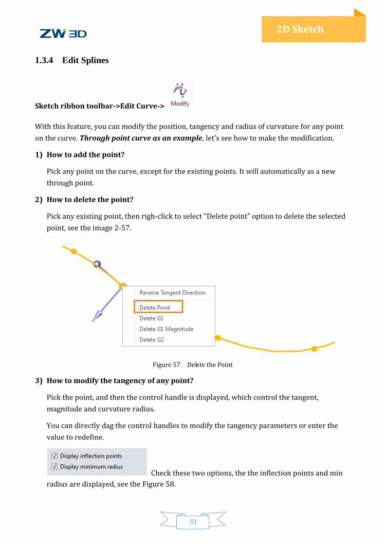
1.3.4 Edit Splines
Sketch ribbon toolbar->Edit Curve->
With this feature, you can modify the position, tangency and radius of curvature for any point
on the curve. Through point curve as an example, let’s see how to make the modification.
1) How to add the point?
Pick any point on the curve, except for the existing points. It will automatically as a new
through point.
2) How to delete the point?
Pick any existing point, then righ-click to select “Delete point” option to delete the selected
point, see the image 2-57.
Figure 57 Delete the Point
3) How to modify the tangency of any point?
Pick the point, and then the control handle is displayed, which control the tangent,
magnitude and curvature radius.
You can directly dag the control handles to modify the tangency parameters or enter the
value to redefine.
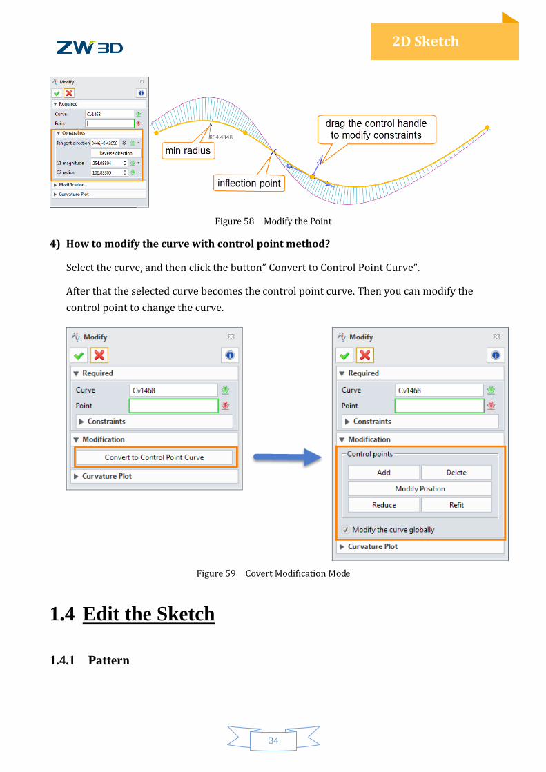
Check these two options, the the inflection points and min
radius are displayed, see the Figure 58.
34
2D Sketch
Figure 58 Modify the Point
4) How to modify the curve with control point method?
Select the curve, and then click the button” Convert to Control Point Curve”.
After that the selected curve becomes the control point curve. Then you can modify the
control point to change the curve.
Figure 59 Covert Modification Mode
1.4 Edit the Sketch
1.4.1 Pattern

35
2D Sketch
Sketch ribbon toolbar->Basic Editing->
In 2D sketch environment, linear pattern and circle pattern are provided.
Type1: Linear Pattern
STEP 01 Select the entities to be patterned.
Notes: The selected geometry is highlighted in orange.
STEP 02 Specify the direction and set the pattern parameters, such as number & pitch distance.
STEP 03 Define 2nd direction and pattern parameters according to the requirements.
STEP 04 If some instances are unneeded, select them to toggle off which displayed in red.
Figure 60 Linear Pattern
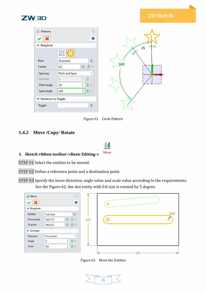
Type2: Circle Pattern
STEP 01 Select the entities to be patterned.
STEP 02 Specify the center point.
STEP 03 Set the pattern parameters, such as pitch angle and span angle.
STEP 04 If some pattern instances are unneeded, select the instance to toggle off.
36
2D Sketch
Figure 61 Circle Pattern
1.4.2 Move /Copy/ Rotate
1. Sketch ribbon toolbar->Basic Editing->
STEP 01 Select the entities to be moved.
STEP 02 Define a reference point and a destination point.
STEP 03 Specify the move direction, angle value and scale value according to the requirements.
See the Figure 62, the slot entity with 0.8 size is rotated by 5 degree.
Figure 62 Move the Entities
37
2D Sketch
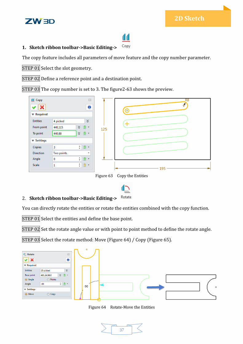
1. Sketch ribbon toolbar->Basic Editing->
The copy feature includes all parameters of move feature and the copy number parameter.
STEP 01 Select the slot geometry.
STEP 02 Define a reference point and a destination point.
STEP 03 The copy number is set to 3. The figure2-63 shows the preview.
Figure 63 Copy the Entities
2. Sketch ribbon toolbar->Basic Editing->
You can directly rotate the entities or rotate the entities combined with the copy function.
STEP 01 Select the entities and define the base point.
STEP 02 Set the rotate angle value or with point to point method to define the rotate angle.
STEP 03 Select the rotate method: Move (Figure 64) / Copy (Figure 65).
Figure 64 Rotate-Move the Entities
38
2D Sketch
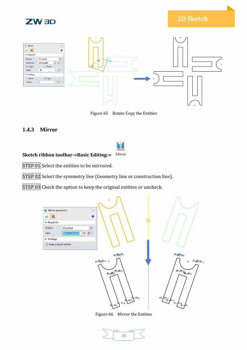
Figure 65 Rotate-Copy the Entities
1.4.3 Mirror
Sketch ribbon toolbar->Basic Editing->
STEP 01 Select the entities to be mirrored.
STEP 02 Select the symmetry line (Geometry line or construction line).
STEP 03 Check the option to keep the original entities or uncheck.
Figure 66 Mirror the Entities
39
2D Sketch
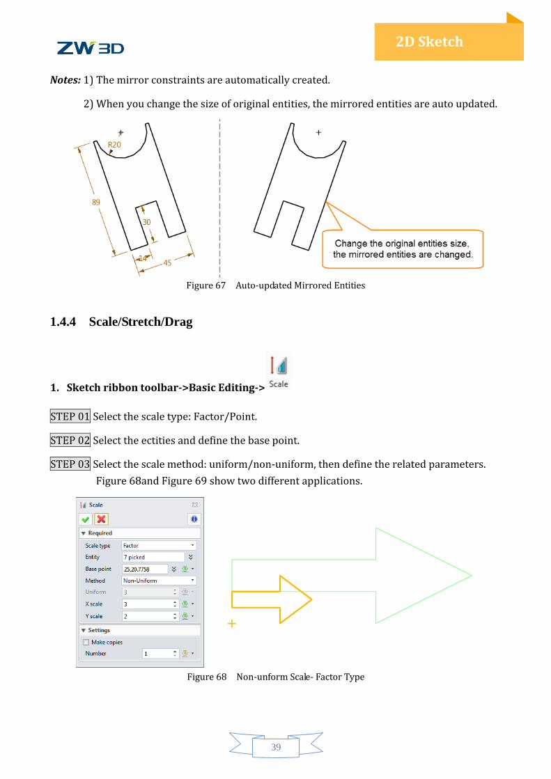
Notes: 1) The mirror constraints are automatically created.
2) When you change the size of original entities, the mirrored entities are auto updated.
Figure 67 Auto-updated Mirrored Entities
1.4.4 Scale/Stretch/Drag
1. Sketch ribbon toolbar->Basic Editing->
STEP 01 Select the scale type: Factor/Point.
STEP 02 Select the ectities and define the base point.
STEP 03 Select the scale method: uniform/non-uniform, then define the related parameters.
Figure 68and Figure 69 show two different applications.
Figure 68 Non-unform Scale- Factor Type
40
2D Sketch
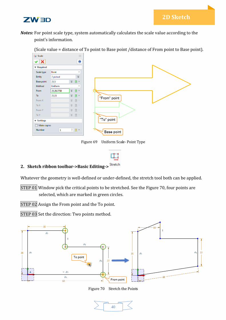
Notes: For point scale type, system automatically calculates the scale value according to the
point’s information.
(Scale value = distance of To point to Base point /distance of From point to Base point).
Figure 69 Uniform Scale- Point Type
2. Sketch ribbon toolbar->Basic Editing->
Whatever the geometry is well-defined or under-defined, the stretch tool both can be applied.
STEP 01 Window pick the critical points to be stretched. See the Figure 70, four points are
selected, which are marked in green circles.
STEP 02 Assign the From point and the To point.
STEP 03 Set the direction: Two points method.
Figure 70 Stretch the Points
41
2D Sketch
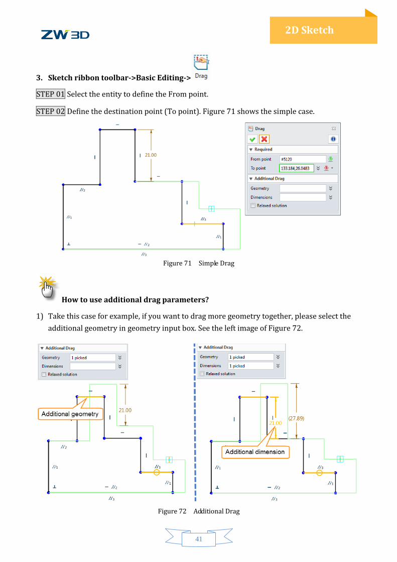
3. Sketch ribbon toolbar->Basic Editing->
STEP 01 Select the entity to define the From point.
STEP 02 Define the destination point (To point). Figure 71 shows the simple case.
Figure 71 Simple Drag
How to use additional drag parameters?
1) Take this case for example, if you want to drag more geometry together, please select the
additional geometry in geometry input box. See the left image of Figure 72.
Figure 72 Additional Drag
42
2D Sketch
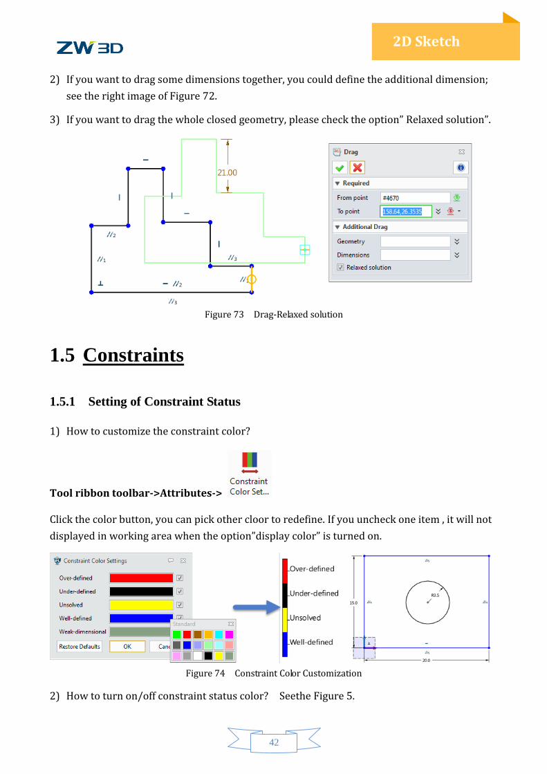
2) If you want to drag some dimensions together, you could define the additional dimension;
see the right image of Figure 72.
3) If you want to drag the whole closed geometry, please check the option” Relaxed solution”.
Figure 73 Drag-Relaxed solution
1.5 Constraints
1.5.1 Setting of Constraint Status
1) How to customize the constraint color?
Tool ribbon toolbar->Attributes->
Click the color button, you can pick other cloor to redefine. If you uncheck one item , it will not
displayed in working area when the option”display color” is turned on.
Figure 74 Constraint Color Customization
2) How to turn on/off constraint status color? Seethe Figure 5.
43
2D Sketch
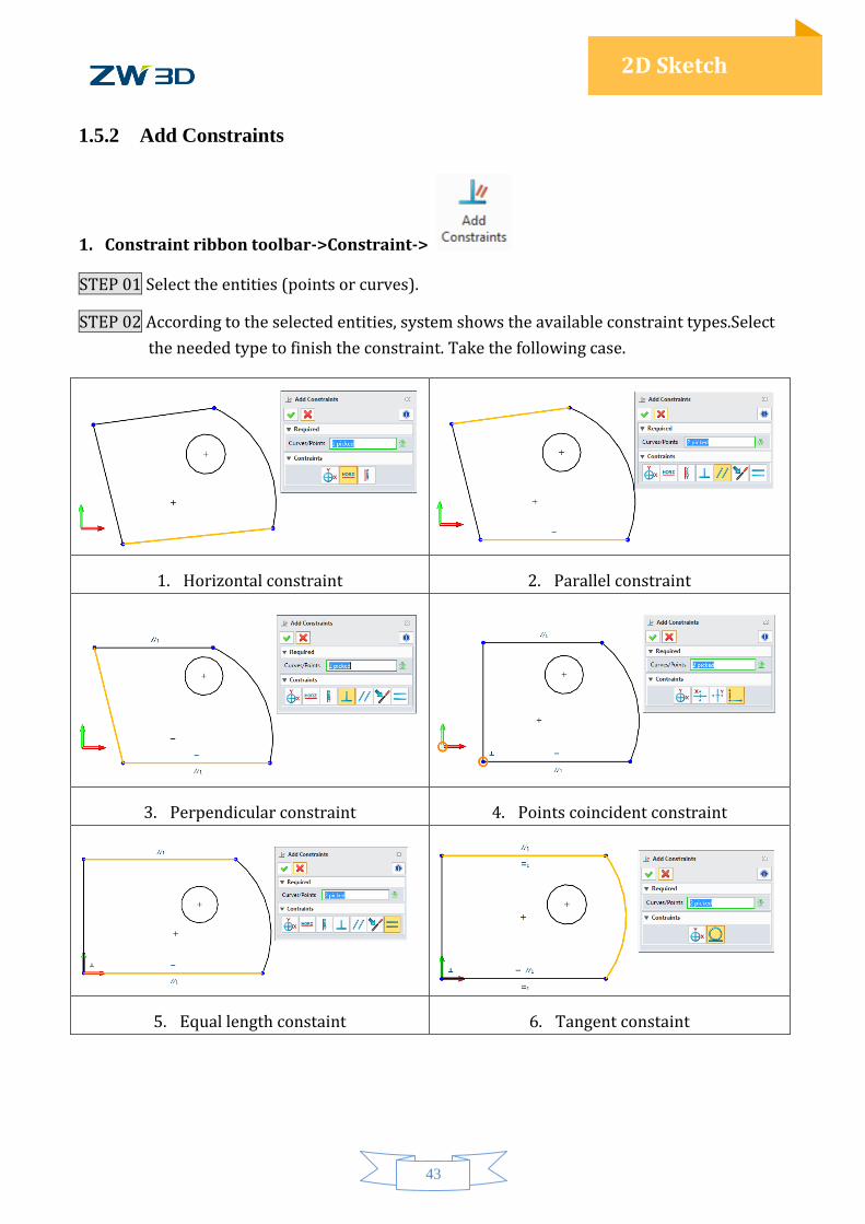
1.5.2 Add Constraints
1. Constraint ribbon toolbar->Constraint->
STEP 01 Select the entities (points or curves).
STEP 02 According to the selected entities, system shows the available constraint types.Select
the needed type to finish the constraint. Take the following case.
1. Horizontal constraint 2. Parallel constraint
3. Perpendicular constraint 4. Points coincident constraint
5. Equal length constaint 6. Tangent constaint
44
2D Sketch
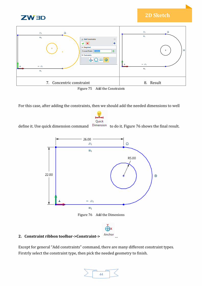
7. Concentric constraint 8. Result
Figure 75 Add the Constraints
For this case, after adding the constraints, then we should add the needed dimensions to well
define it. Use quick dimension command to do it. Figure 76 shows the final result.
Figure 76 Add the Dimenions
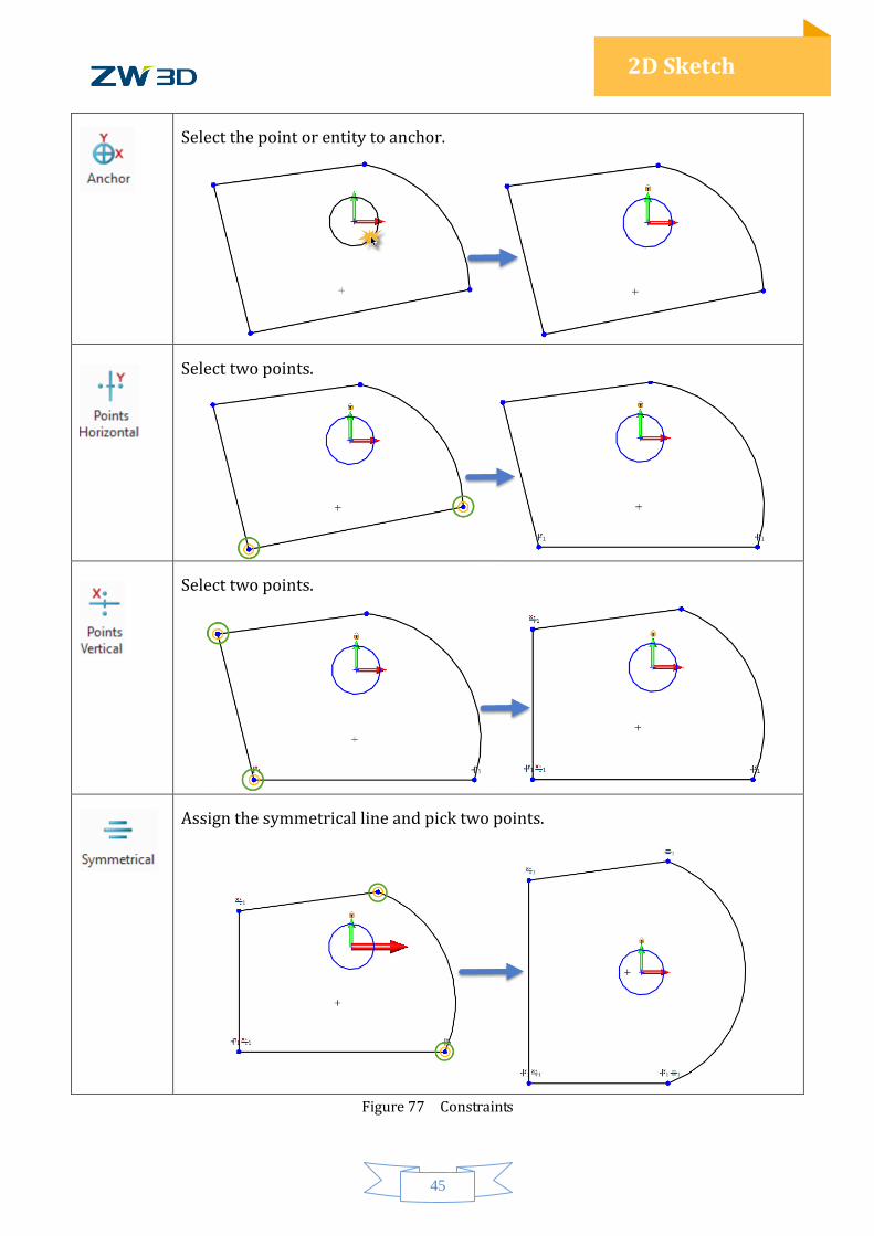
2. Constraint ribbon toolbar->Constraint-> …
Except for general “Add constraints” command, there are many different constraint types.
Firstrly select the constraint type, then pick the needed geometry to finish.
45
2D Sketch
Select the point or entity to anchor.
Select two points.
Select two points.
Assign the symmetrical line and pick two points.
Figure 77 Constraints
46
2D Sketch
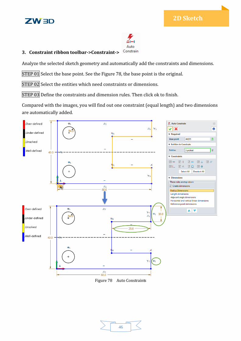
3. Constraint ribbon toolbar->Constraint->
Analyze the selected sketch geometry and automatically add the constraints and dimensions.
STEP 01 Select the base point. See the Figure 78, the base point is the original.
STEP 02 Select the entities which need constraints or dimensions.
STEP 03 Define the constraints and dimension rules. Then click ok to finish.
Compared with the images, you will find out one constraint (equal length) and two dimensions
are automatically added.
Figure 78 Auto Constraints
47
2D Sketch
1.5.3 Inquire Constraints and Constraint Status
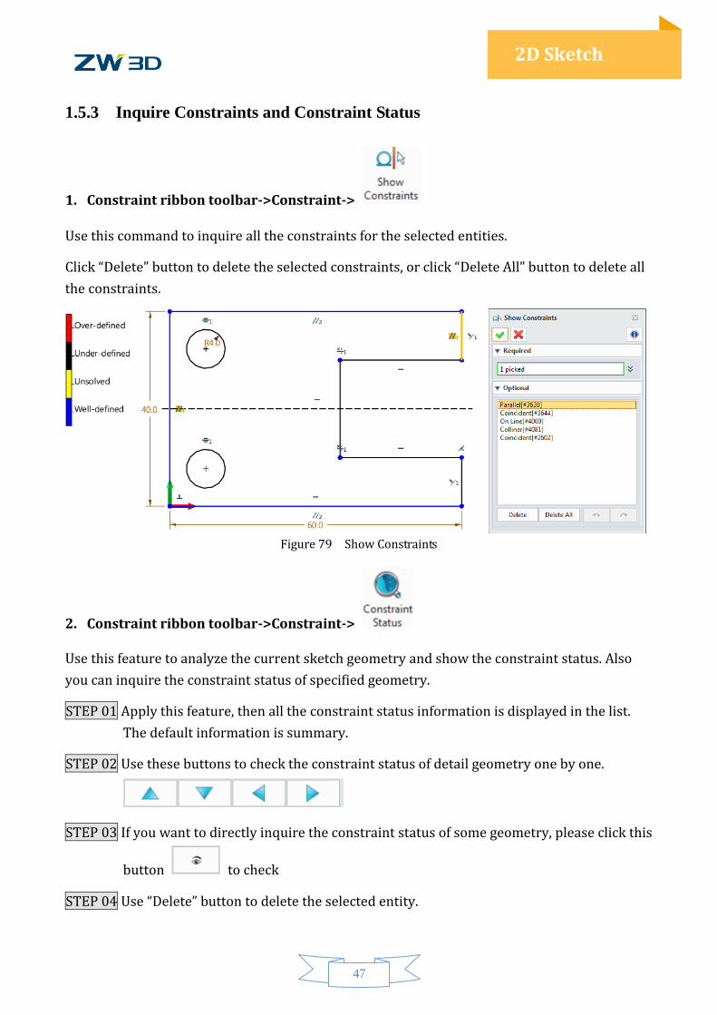
1. Constraint ribbon toolbar->Constraint->
Use this command to inquire all the constraints for the selected entities.
Click “Delete” button to delete the selected constraints, or click “Delete All” button to delete all
the constraints.
Figure 79 Show Constraints
2. Constraint ribbon toolbar->Constraint->
Use this feature to analyze the current sketch geometry and show the constraint status. Also
you can inquire the constraint status of specified geometry.
STEP 01 Apply this feature, then all the constraint status information is displayed in the list.
The default information is summary.
STEP 02 Use these buttons to check the constraint status of detail geometry one by one.
STEP 03 If you want to directly inquire the constraint status of some geometry, please click this
button to check
STEP 04 Use “Delete” button to delete the selected entity.
48
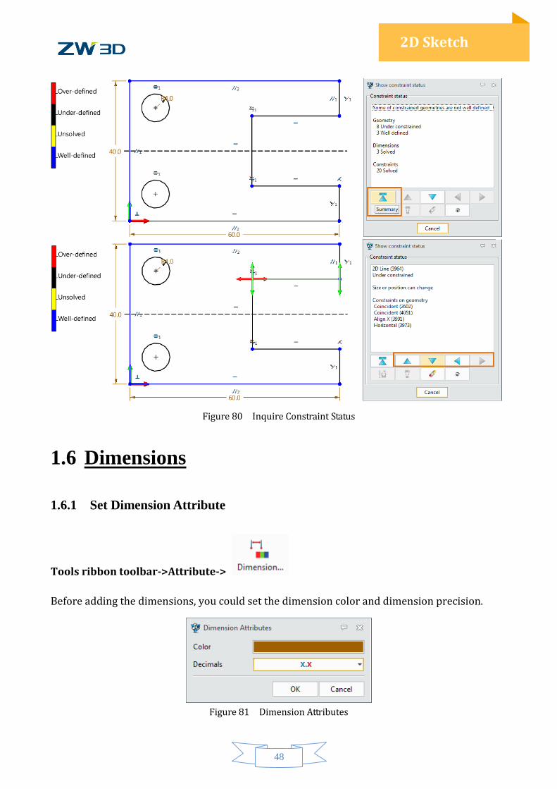
2D Sketch
Figure 80 Inquire Constraint Status
1.6 Dimensions
1.6.1 Set Dimension Attribute
Tools ribbon toolbar->Attribute->
Before adding the dimensions, you could set the dimension color and dimension precision.
Figure 81 Dimension Attributes
49
2D Sketch
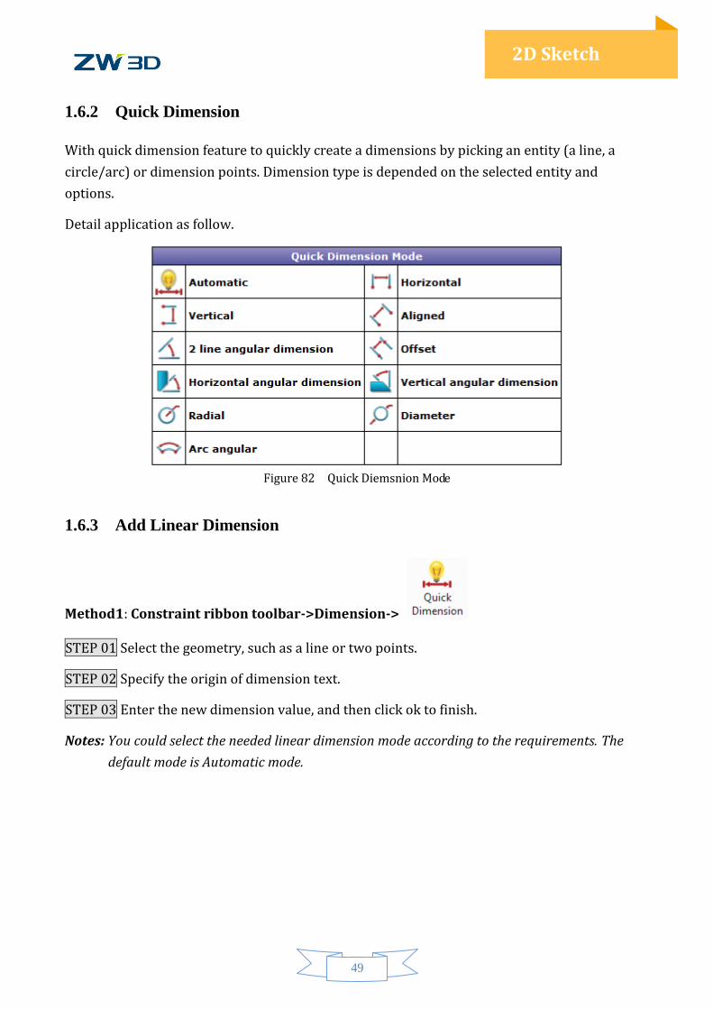
1.6.2 Quick Dimension
With quick dimension feature to quickly create a dimensions by picking an entity (a line, a
circle/arc) or dimension points. Dimension type is depended on the selected entity and
options.
Detail application as follow.
Figure 82 Quick Diemsnion Mode
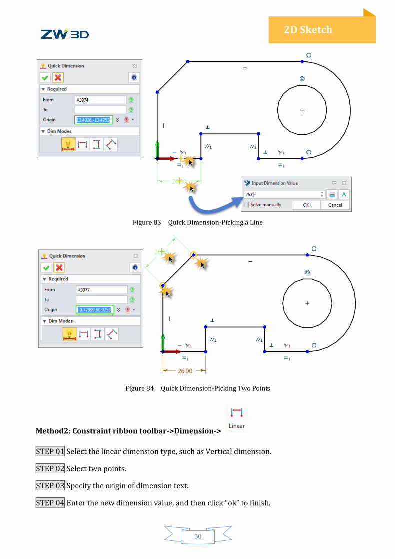
1.6.3 Add Linear Dimension
Method1: Constraint ribbon toolbar->Dimension->
STEP 01 Select the geometry, such as a line or two points.
STEP 02 Specify the origin of dimension text.
STEP 03 Enter the new dimension value, and then click ok to finish.
Notes: You could select the needed linear dimension mode according to the requirements. The
default mode is Automatic mode.
50
2D Sketch
Figure 83 Quick Dimension-Picking a Line
Figure 84 Quick Dimension-Picking Two Points
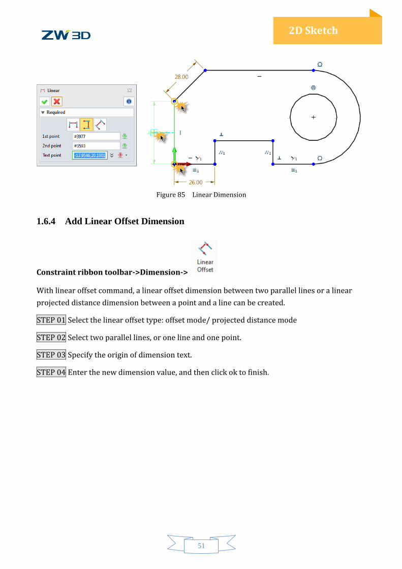
Method2: Constraint ribbon toolbar->Dimension->
STEP 01 Select the linear dimension type, such as Vertical dimension.
STEP 02 Select two points.
STEP 03 Specify the origin of dimension text.
STEP 04 Enter the new dimension value, and then click “ok” to finish.
51
2D Sketch
Figure 85 Linear Dimension
1.6.4 Add Linear Offset Dimension
Constraint ribbon toolbar->Dimension->
With linear offset command, a linear offset dimension between two parallel lines or a linear
projected distance dimension between a point and a line can be created.
STEP 01 Select the linear offset type: offset mode/ projected distance mode
STEP 02 Select two parallel lines, or one line and one point.
STEP 03 Specify the origin of dimension text.
STEP 04 Enter the new dimension value, and then click ok to finish.
52
2D Sketch
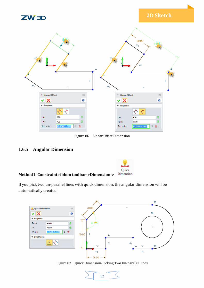
Figure 86 Linear Offset Dimension
1.6.5 Angular Dimension
Method1: Constraint ribbon toolbar->Dimension->
If you pick two un-parallel lines with quick dimension, the angular dimension will be
automatically created.
Figure 87 Quick Dimension-Picking Two Un-parallel Lines
53
2D Sketch
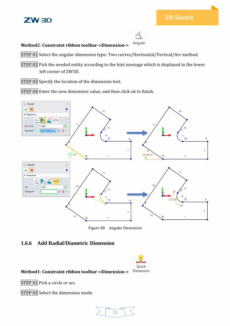
Method2: Constraint ribbon toolbar->Dimension->
STEP 01 Select the angular dimension type: Two curves/Horizontal/Vertical/Arc method.
STEP 02 Pick the needed entity according to the hint message which is displayed in the lower
left corner of ZW3D.
STEP 03 Specify the location of the dimension text.
STEP 04 Enter the new dimension value, and then click ok to finish.
Figure 88 Angular Diemsnion
1.6.6 Add Radial/Diametric Dimension
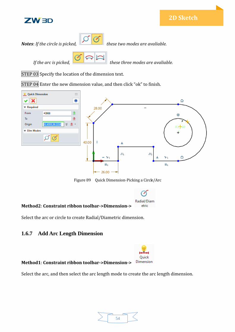
Method1: Constraint ribbon toolbar->Dimension->
STEP 01 Pick a circle or arc.
STEP 02 Select the dimension mode.
54
2D Sketch
Notes: If the circle is picked, these two modes are avaliable.
If the arc is picked, these three modes are avaliable.
STEP 03 Specify the location of the dimension text.
STEP 04 Enter the new dimension value, and then click “ok” to finish.
Figure 89 Quick Dimension-Picking a Circle/Arc
Method2: Constraint ribbon toolbar->Dimension->
Select the arc or circle to create Radial/Diametric dimension.
1.6.7 Add Arc Length Dimension
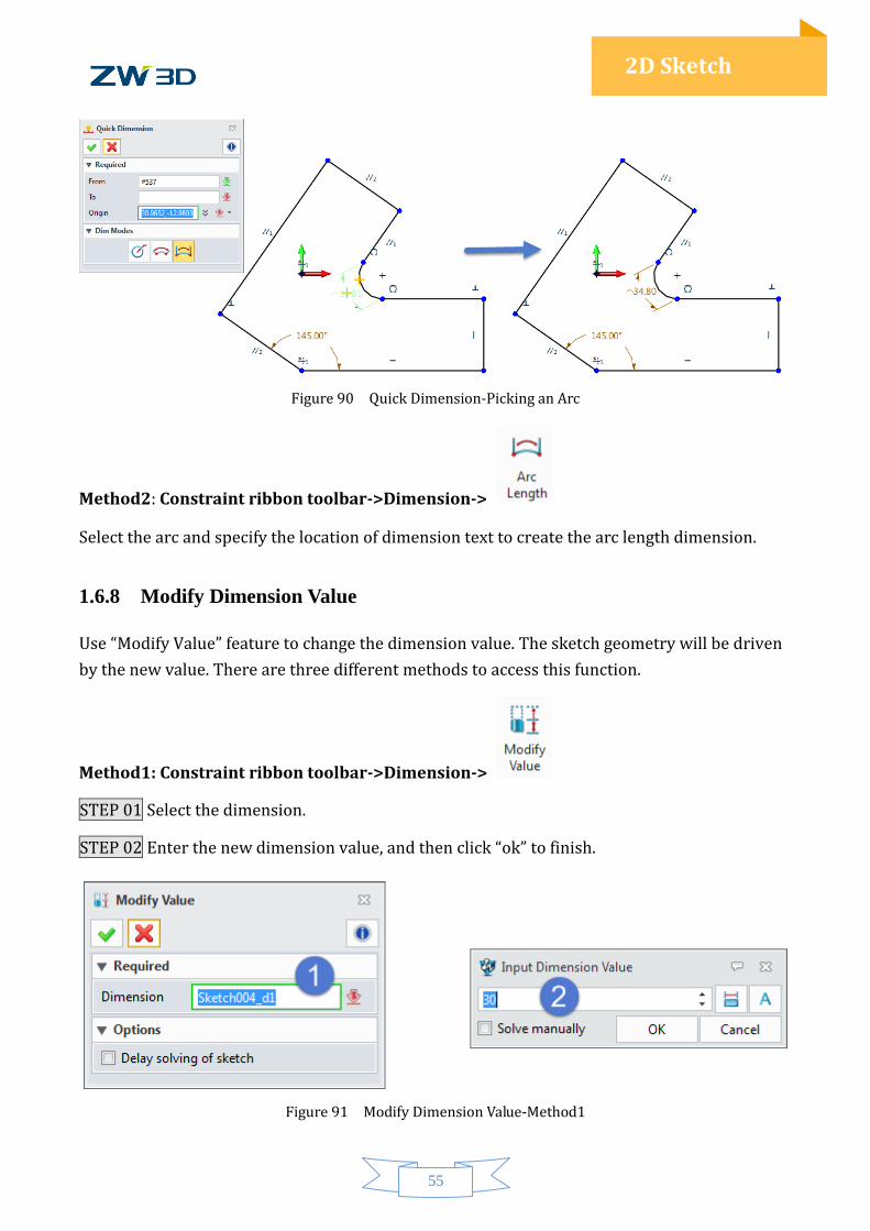
Method1: Constraint ribbon toolbar->Dimension->
Select the arc, and then select the arc length mode to create the arc length dimension.
55
2D Sketch
Figure 90 Quick Dimension-Picking an Arc
Method2: Constraint ribbon toolbar->Dimension->
Select the arc and specify the location of dimension text to create the arc length dimension.
1.6.8 Modify Dimension Value
Use “Modify Value” feature to change the dimension value. The sketch geometry will be driven
by the new value. There are three different methods to access this function.
Method1: Constraint ribbon toolbar->Dimension->
STEP 01 Select the dimension.
STEP 02 Enter the new dimension value, and then click “ok” to finish.
Figure 91 Modify Dimension Value-Method1
56
2D Sketch
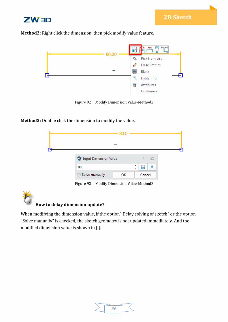
Method2: Right click the dimension, then pick modify value feature.
Figure 92 Modify Dimension Value-Method2
Method3: Double click the dimension to modify the value.
Figure 93 Modify Dimension Value-Method3
How to delay dimension update?
When modifying the dimension value, if the option” Delay solving of sketch” or the option
“Solve manually” is checked, the sketch geometry is not updated immediately. And the
modified dimension value is shown in [ ].

57
2D Sketch
Figure 94 Delay Dimension Update
When the next Solve Current Sketch command is executed, the sketch will be updated.
Figure 95 Update Dimension Value Manually
Notes: If many dimensions value need to be modified in a sketch, the delayed dimension update
function is recommended. The sketch only needs one update to avoid the distorted geometry
happen during several updates.
58
2D Sketch
1.7 Check the Sketch
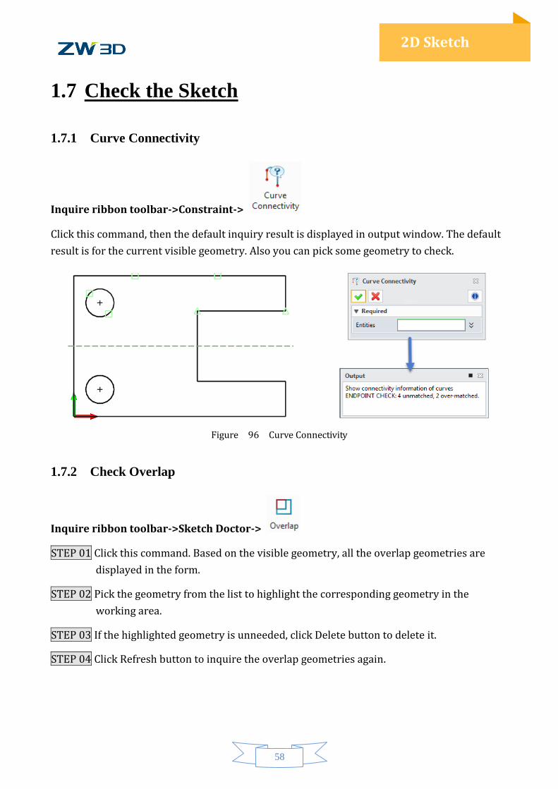
1.7.1 Curve Connectivity
Inquire ribbon toolbar->Constraint->
Click this command, then the default inquiry result is displayed in output window. The default
result is for the current visible geometry. Also you can pick some geometry to check.
Figure 96 Curve Connectivity
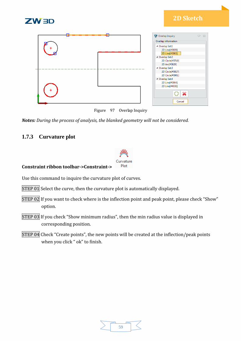
1.7.2 Check Overlap
Inquire ribbon toolbar->Sketch Doctor->
STEP 01 Click this command. Based on the visible geometry, all the overlap geometries are
displayed in the form.
STEP 02 Pick the geometry from the list to highlight the corresponding geometry in the
working area.
STEP 03 If the highlighted geometry is unneeded, click Delete button to delete it.
STEP 04 Click Refresh button to inquire the overlap geometries again.
59
2D Sketch
Figure 97 Overlap Inquiry
Notes: During the process of analysis, the blanked geometry will not be considered.
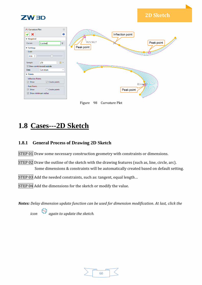
1.7.3 Curvature plot
Constraint ribbon toolbar->Constraint->
Use this command to inquire the curvature plot of curves.
STEP 01 Select the curve, then the curvature plot is automatically displayed.
STEP 02 If you want to check where is the inflection point and peak point, please check “Show”
option.
STEP 03 If you check “Show minimum radius”, then the min radius value is displayed in
corresponding position.
STEP 04 Check “Create points”, the new points will be created at the inflection/peak points
when you click “ ok” to finish.
60
2D Sketch
Figure 98 Curvature Plot
1.8 Cases---2D Sketch
1.8.1 General Process of Drawing 2D Sketch
STEP 01 Draw some necessary construction geometry with constraints or dimensions.
STEP 02 Draw the outline of the sketch with the drawing features (such as, line, circle, arc).
Some dimensions & constraints will be automatically created based on default setting.
STEP 03 Add the needed constraints, such as: tangent, equal length…
STEP 04 Add the dimensions for the sketch or modify the value.
Notes: Delay dimension update function can be used for dimension modification. At last, click the
icon again to update the sketch.
61
2D Sketch
1.8.2 Case1
STEP 01 Set the sketch dimension attribute. See the Figure 99.
Figure 99 Set Dimension Attribute
STEP 02 With Line feature to draw a horizontal line through the origin, and then convert it to
construction line.
STEP 03 Draw a vertical construction line and set the distance between the line and the origin
as 150 (mm), as shown in Figure 100.
Figure 100 Construction Geometry
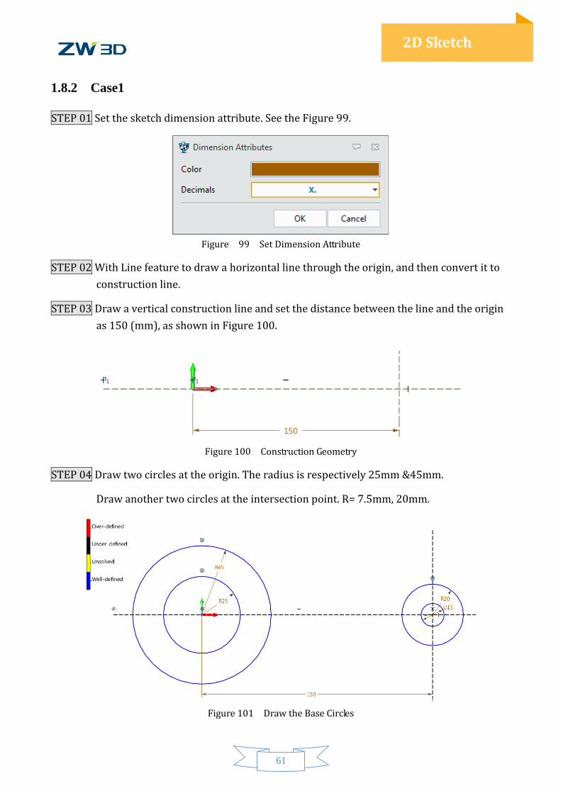
STEP 04 Draw two circles at the origin. The radius is respectively 25mm &45mm.
Draw another two circles at the intersection point. R= 7.5mm, 20mm.
Figure 101 Draw the Base Circles
62
2D Sketch
STEP 05 Add the constraint for the circle center and intersection point with “Point to
Intersection” feature. Turn on “constraint status color”, and then check the sketch.
The result is shown in the Figure 101.
STEP 06 Draw two horizontal lines tanged with the circle of radicus=20mm. Then trim the
sketch. The recommend features is “One Touch Trim”. See the Figure 102.
Figure 102 Add Two Horizontal Lines
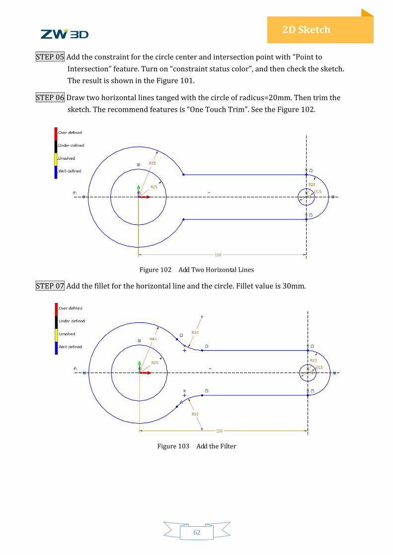
STEP 07 Add the fillet for the horizontal line and the circle. Fillet value is 30mm.
Figure 103 Add the Filter
63
2D Sketch
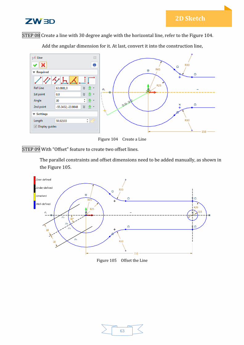
STEP 08 Create a line with 30 degree angle with the horizontal line, refer to the Figure 104.
Add the angular dimension for it. At last, convert it into the construction line,
Figure 104 Create a Line
STEP 09 With “Offset” feature to create two offset lines.
The parallel constraints and offset dimensions need to be added manually, as shown in
the Figure 105.
Figure 105 Offset the Line
64
2D Sketch
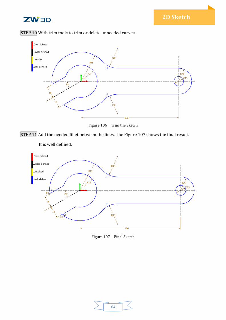
STEP 10 With trim tools to trim or delete unneeded curves.
Figure 106 Trim the Sketch
STEP 11 Add the needed fillet between the lines. The Figure 107 shows the final result.
It is well defined.
Figure 107 Final Sketch
65
2D Sketch
1.8.3 Case2
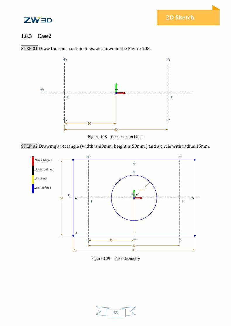
STEP 01 Draw the construction lines, as shown in the Figure 108.
Figure 108 Construction Lines
STEP 02 Drawing a rectangle (width is 80mm; height is 50mm.) and a circle with radius 15mm.
Figure 109 Base Geometry
66
2D Sketch
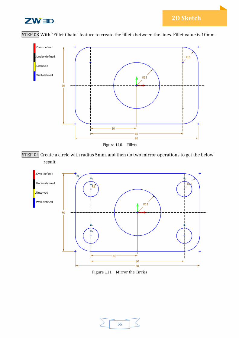
STEP 03 With “Fillet Chain” feature to create the fillets between the lines. Fillet value is 10mm.
Figure 110 Fillets
STEP 04 Create a circle with radius 5mm, and then do two mirror operations to get the below
result.
Figure 111 Mirror the Circles
67
2D Sketch
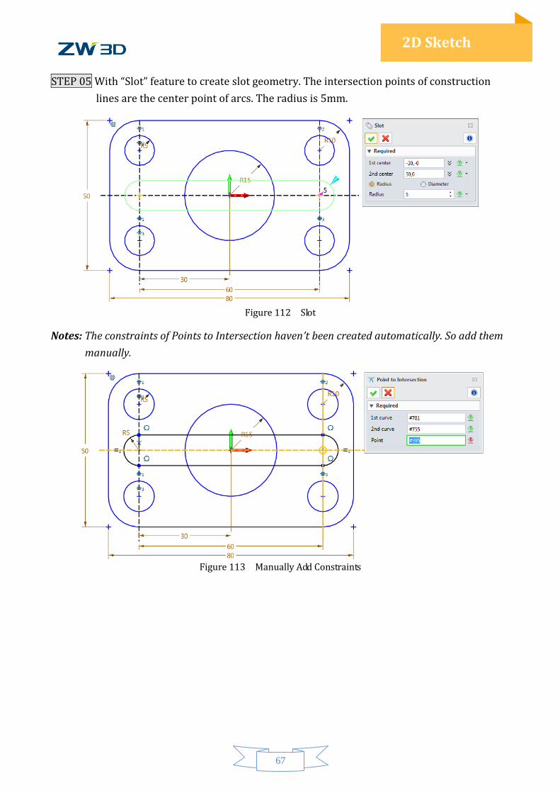
STEP 05 With “Slot” feature to create slot geometry. The intersection points of construction
lines are the center point of arcs. The radius is 5mm.
Figure 112 Slot
Notes: The constraints of Points to Intersection haven’t been created automatically. So add them
manually.
Figure 113 Manually Add Constraints
68
2D Sketch
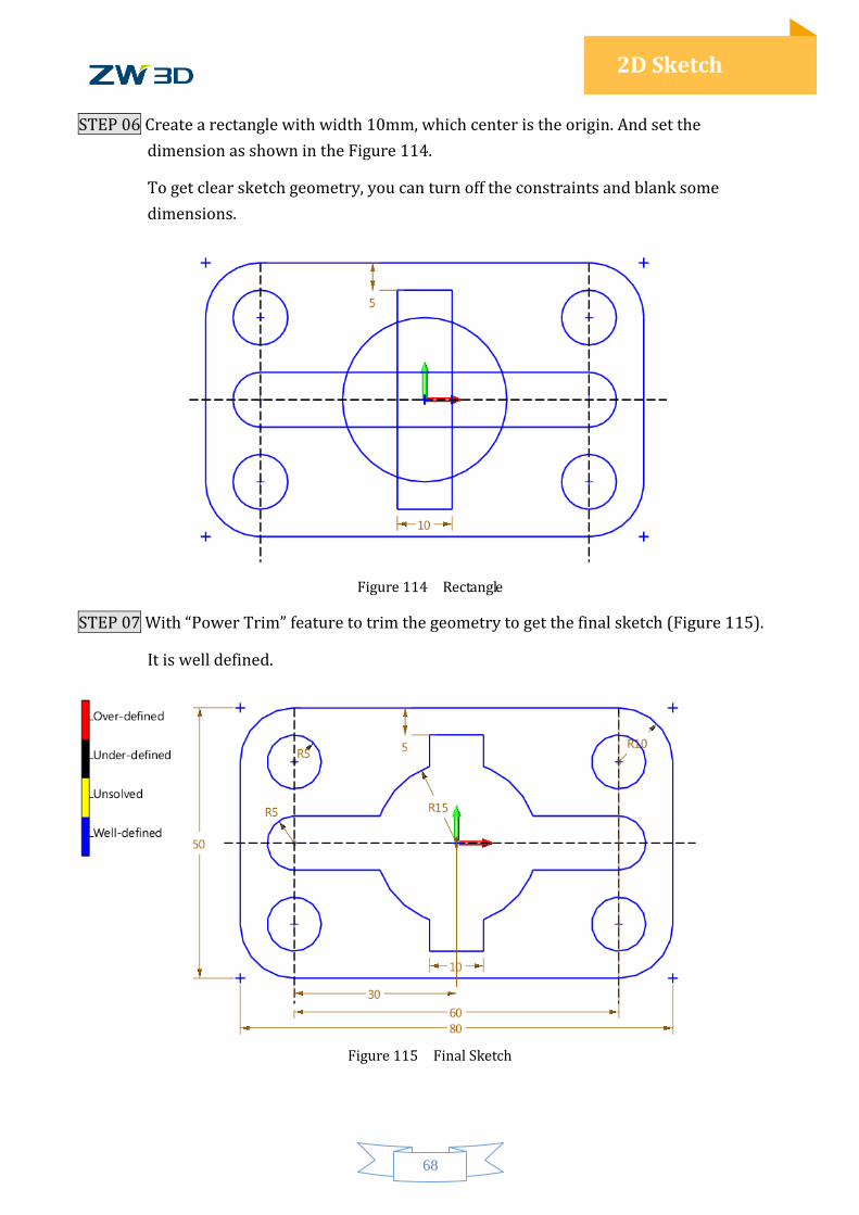
STEP 06 Create a rectangle with width 10mm, which center is the origin. And set the
dimension as shown in the Figure 114.
To get clear sketch geometry, you can turn off the constraints and blank some
dimensions.
Figure 114 Rectangle
STEP 07 With “Power Trim” feature to trim the geometry to get the final sketch (Figure 115).
It is well defined.
Figure 115 Final Sketch
69
2D Sketch
1.9 Exercises
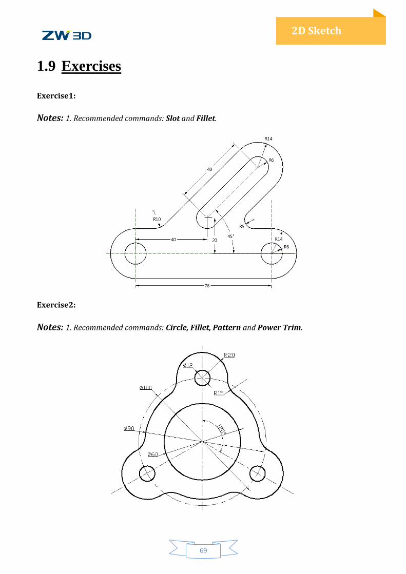
Exercise1:
Notes: 1. Recommended commands: Slot and Fillet.
Exercise2:
Notes: 1. Recommended commands: Circle, Fillet, Pattern and Power Trim.
70
2D Sketch
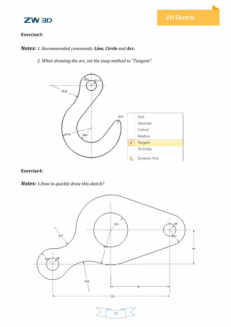
Exercise3:
Notes: 1. Recommended commands: Line, Circle and Arc.
2. When drawing the arc, set the snap method to “Tangent”.
Exercise4:
Notes: 1.How to quickly draw this sketch?