Embed Size (px)
Citation preview
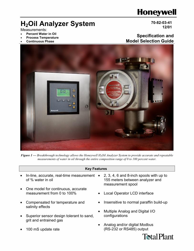
H2Oil Analyzer SystemMeasurements:• Percent Water in Oil• Process Temperature• Continuous Phase
70-82-03-4112/01
Specification andModel Selection Guide
Figure 1 — Breakthrough technology allows the Honeywell H2Oil Analyzer System to provide accurate and repeatablemeasurements of water in oil through the entire composition range of 0 to 100 percent water.
Key Features
• In-line, accurate, real-time measurementof % water in oil
• One model for continuous, accuratemeasurement from 0 to 100%
• Compensated for temperature andsalinity effects
• Superior sensor design tolerant to sand,grit and entrained gas
• 100 mS update rate
• 2, 3, 4, 6 and 8-inch spools with up to155 meters between analyzer andmeasurement spool
• Local Operator LCD interface
• Insensitive to normal paraffin build-up
• Multiple Analog and Digital I/Oconfigurations
• Analog and/or digital Modbus(RS-232 or RS485) output
H2Oil Analyzer System
70-82-03-412
H2Oil Analyzer System – Application Overview
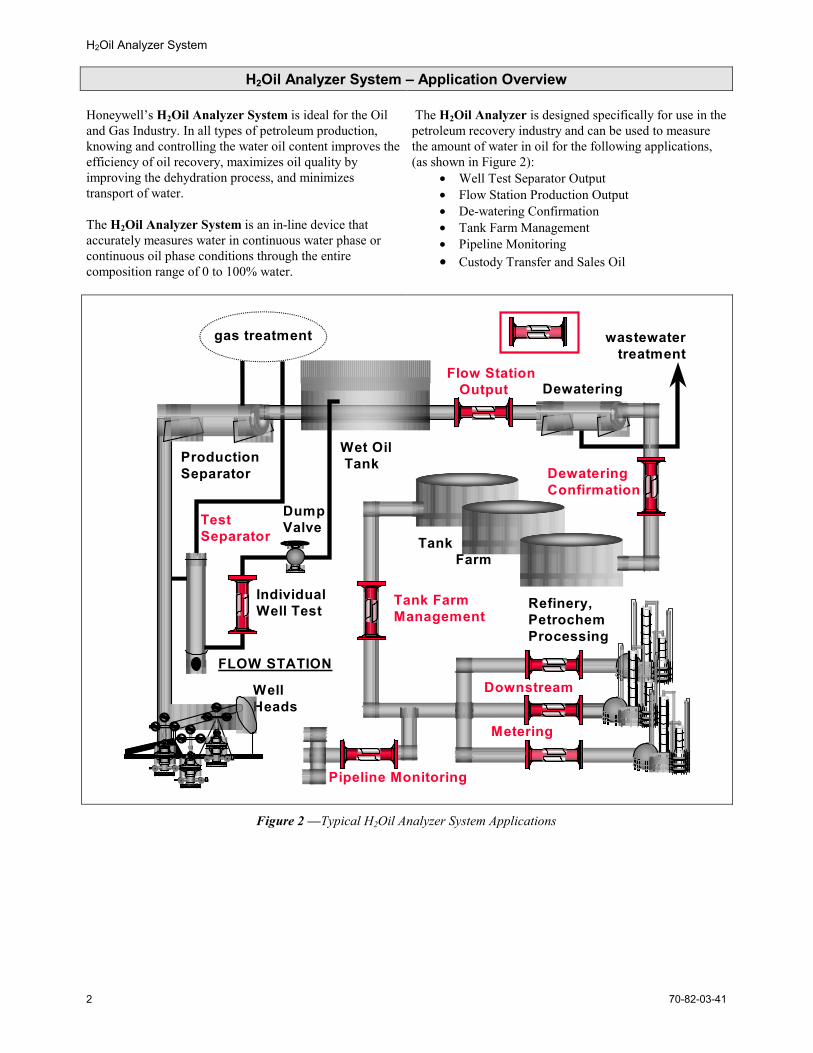
Honeywell’s H2Oil Analyzer System is ideal for the Oiland Gas Industry. In all types of petroleum production,knowing and controlling the water oil content improves theefficiency of oil recovery, maximizes oil quality byimproving the dehydration process, and minimizestransport of water.
The H2Oil Analyzer System is an in-line device thataccurately measures water in continuous water phase orcontinuous oil phase conditions through the entirecomposition range of 0 to 100% water.
The H2Oil Analyzer is designed specifically for use in thepetroleum recovery industry and can be used to measurethe amount of water in oil for the following applications,(as shown in Figure 2):
• Well Test Separator Output• Flow Station Production Output• De-watering Confirmation• Tank Farm Management• Pipeline Monitoring• Custody Transfer and Sales Oil
gas treatment
WellHeads
TestSeparator
DumpValve
Flow Station Output
Wet Oil TankProduction
Separator
Dewatering
wastewater treatment
DewateringConfirmation
Downstream
Metering
Pipeline Monitoring
Tank FarmManagement
IndividualWell Test
Tank Farm
FLOW STATION
Refinery,PetrochemProcessing
Figure 2 —Typical H2Oil Analyzer System Applications
H2Oil Analyzer System
70-82-03-41 3
Well Testing
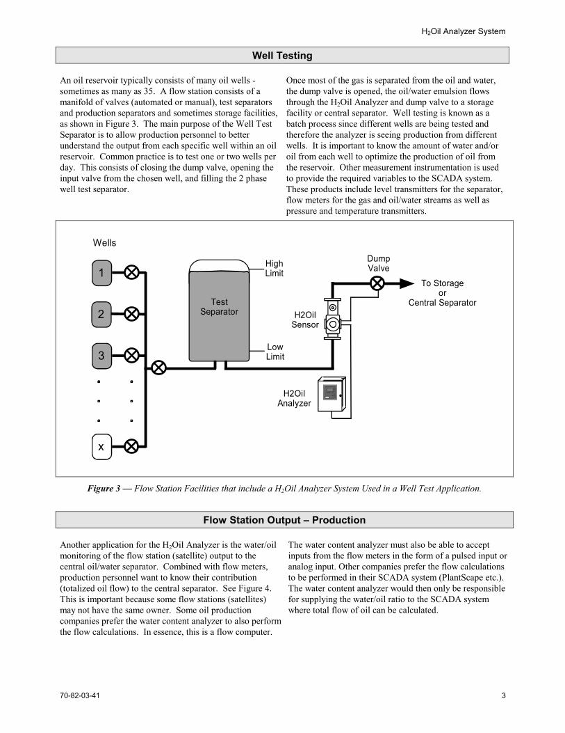
An oil reservoir typically consists of many oil wells -sometimes as many as 35. A flow station consists of amanifold of valves (automated or manual), test separatorsand production separators and sometimes storage facilities,as shown in Figure 3. The main purpose of the Well TestSeparator is to allow production personnel to betterunderstand the output from each specific well within an oilreservoir. Common practice is to test one or two wells perday. This consists of closing the dump valve, opening theinput valve from the chosen well, and filling the 2 phasewell test separator.
Once most of the gas is separated from the oil and water,the dump valve is opened, the oil/water emulsion flowsthrough the H2Oil Analyzer and dump valve to a storagefacility or central separator. Well testing is known as abatch process since different wells are being tested andtherefore the analyzer is seeing production from differentwells. It is important to know the amount of water and/oroil from each well to optimize the production of oil fromthe reservoir. Other measurement instrumentation is usedto provide the required variables to the SCADA system.These products include level transmitters for the separator,flow meters for the gas and oil/water streams as well aspressure and temperature transmitters.
TestSeparator
Wells
1
3
x
2 H2OilSensor
HighLimit
LowLimit
DumpValve
H2OilAnalyzer
To Storageor
Central Separator
Figure 3 — Flow Station Facilities that include a H2Oil Analyzer System Used in a Well Test Application.
Flow Station Output – Production
Another application for the H2Oil Analyzer is the water/oilmonitoring of the flow station (satellite) output to thecentral oil/water separator. Combined with flow meters,production personnel want to know their contribution(totalized oil flow) to the central separator. See Figure 4.This is important because some flow stations (satellites)may not have the same owner. Some oil productioncompanies prefer the water content analyzer to also performthe flow calculations. In essence, this is a flow computer.
The water content analyzer must also be able to acceptinputs from the flow meters in the form of a pulsed input oranalog input. Other companies prefer the flow calculationsto be performed in their SCADA system (PlantScape etc.).The water content analyzer would then only be responsiblefor supplying the water/oil ratio to the SCADA systemwhere total flow of oil can be calculated.
H2Oil Analyzer System
70-82-03-414
Flow meterStorage
Tank
GasTreatment
H2OilSensor
Wells
1
3
x
2
H2OilAnalyzer
ProductionSeparator
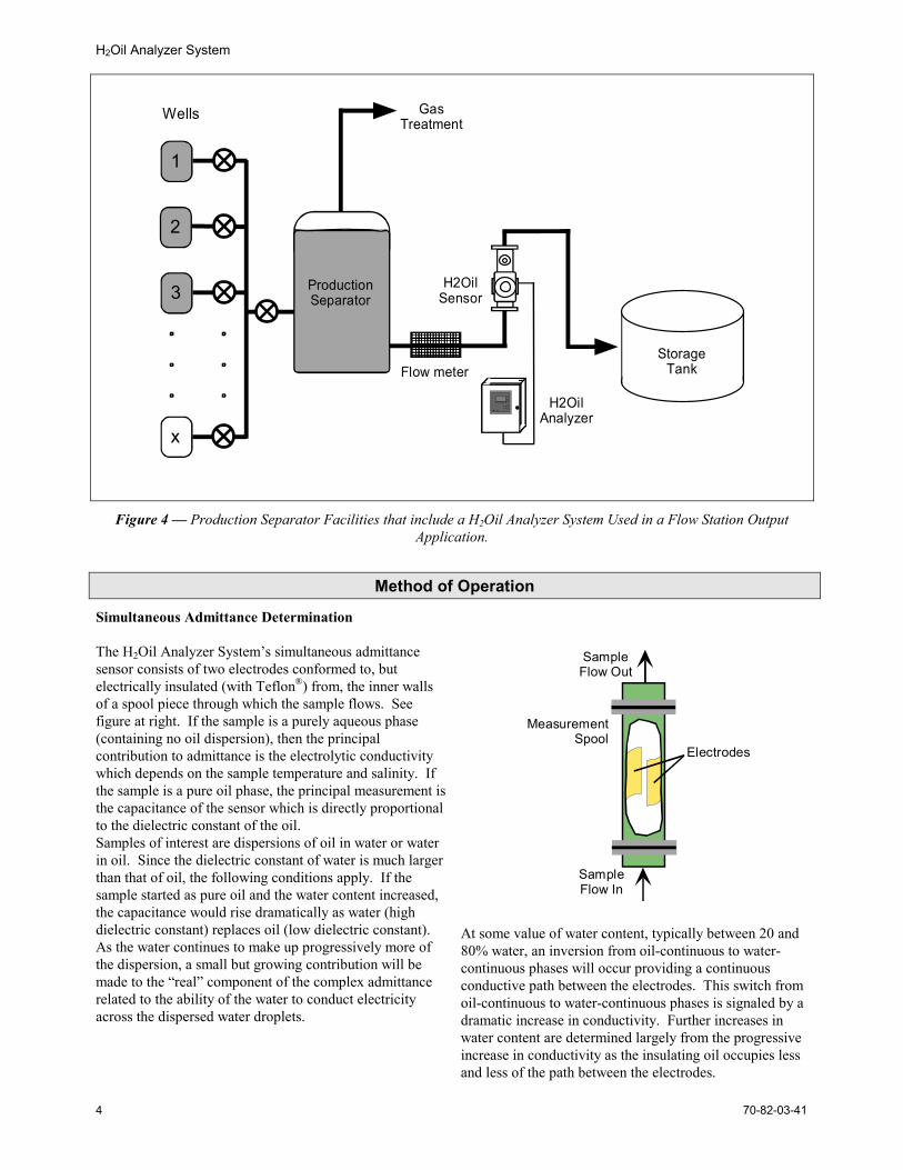
Figure 4 — Production Separator Facilities that include a H2Oil Analyzer System Used in a Flow Station OutputApplication.
Method of Operation
Simultaneous Admittance Determination
The H2Oil Analyzer System’s simultaneous admittancesensor consists of two electrodes conformed to, butelectrically insulated (with Teflon®) from, the inner wallsof a spool piece through which the sample flows. Seefigure at right. If the sample is a purely aqueous phase(containing no oil dispersion), then the principalcontribution to admittance is the electrolytic conductivitywhich depends on the sample temperature and salinity. Ifthe sample is a pure oil phase, the principal measurement isthe capacitance of the sensor which is directly proportionalto the dielectric constant of the oil.Samples of interest are dispersions of oil in water or waterin oil. Since the dielectric constant of water is much largerthan that of oil, the following conditions apply. If thesample started as pure oil and the water content increased,the capacitance would rise dramatically as water (highdielectric constant) replaces oil (low dielectric constant).As the water continues to make up progressively more ofthe dispersion, a small but growing contribution will bemade to the “real” component of the complex admittancerelated to the ability of the water to conduct electricityacross the dispersed water droplets.
SampleFlow In
SampleFlow Out
Electrodes
MeasurementSpool
At some value of water content, typically between 20 and80% water, an inversion from oil-continuous to water-continuous phases will occur providing a continuousconductive path between the electrodes. This switch fromoil-continuous to water-continuous phases is signaled by adramatic increase in conductivity. Further increases inwater content are determined largely from the progressiveincrease in conductivity as the insulating oil occupies lessand less of the path between the electrodes.
H2Oil Analyzer System
70-82-03-41 5
H2Oil Analyzer System Specifications
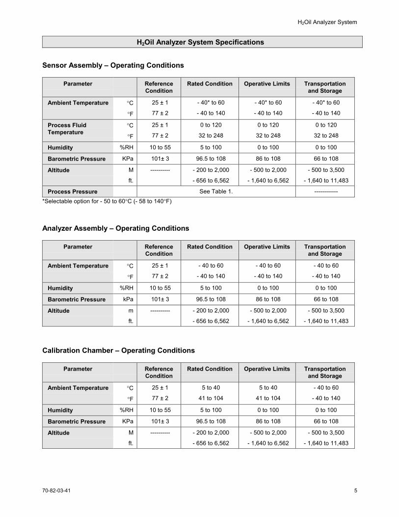
Sensor Assembly – Operating Conditions
Parameter ReferenceCondition
Rated Condition Operative Limits Transportationand Storage
Ambient Temperature °C
°F
25 ± 1
77 ± 2
- 40* to 60
- 40 to 140
- 40* to 60
- 40 to 140
- 40* to 60
- 40 to 140
Process FluidTemperature
°C
°F
25 ± 1
77 ± 2
0 to 120
32 to 248
0 to 120
32 to 248
0 to 120
32 to 248
Humidity %RH 10 to 55 5 to 100 0 to 100 0 to 100
Barometric Pressure KPa 101± 3 96.5 to 108 86 to 108 66 to 108
Altitude M
ft.
---------- - 200 to 2,000
- 656 to 6,562
- 500 to 2,000
- 1,640 to 6,562
- 500 to 3,500
- 1,640 to 11,483
Process Pressure See Table 1. ------------*Selectable option for - 50 to 60°C (- 58 to 140°F)
Analyzer Assembly – Operating Conditions
Parameter ReferenceCondition
Rated Condition Operative Limits Transportationand Storage
Ambient Temperature °C
°F
25 ± 1
77 ± 2
- 40 to 60
- 40 to 140
- 40 to 60
- 40 to 140
- 40 to 60
- 40 to 140
Humidity %RH 10 to 55 5 to 100 0 to 100 0 to 100
Barometric Pressure kPa 101± 3 96.5 to 108 86 to 108 66 to 108
Altitude m
ft.
---------- - 200 to 2,000
- 656 to 6,562
- 500 to 2,000
- 1,640 to 6,562
- 500 to 3,500
- 1,640 to 11,483
Calibration Chamber – Operating Conditions
Parameter ReferenceCondition
Rated Condition Operative Limits Transportationand Storage
Ambient Temperature °C
°F
25 ± 1
77 ± 2
5 to 40
41 to 104
5 to 40
41 to 104
- 40 to 60
- 40 to 140
Humidity %RH 10 to 55 5 to 100 0 to 100 0 to 100
Barometric Pressure KPa 101± 3 96.5 to 108 86 to 108 66 to 108
Altitude M
ft.
---------- - 200 to 2,000
- 656 to 6,562
- 500 to 2,000
- 1,640 to 6,562
- 500 to 3,500
- 1,640 to 11,483
H2Oil Analyzer System
70-82-03-416
H2Oil Analyzer System Specifications, cont’d
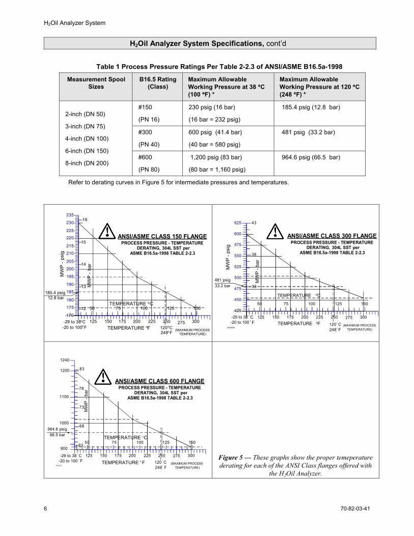
Table 1 Process Pressure Ratings Per Table 2-2.3 of ANSI/ASME B16.5a-1998
Measurement SpoolSizes
B16.5 Rating(Class)
Maximum AllowableWorking Pressure at 38 °°°°C(100 °°°°F) *
Maximum AllowableWorking Pressure at 120 °°°°C(248 °°°°F) *
#150
(PN 16)
230 psig (16 bar)
(16 bar = 232 psig)
185.4 psig (12.8 bar)
#300
(PN 40)
600 psig (41.4 bar)
(40 bar = 580 psig)
481 psig (33.2 bar)
2-inch (DN 50)
3-inch (DN 75)
4-inch (DN 100)
6-inch (DN 150)
8-inch (DN 200)#600
(PN 80)
1,200 psig (83 bar)
(80 bar = 1,160 psig)
964.6 psig (66.5 bar)
Refer to derating curves in Figure 5 for intermediate pressures and temperatures.
MW
P -
psig
125 150 175 200 225 250 275 300
ANSI/ASME CLASS 150 FLANGEPROCESS PRESSURE - TEMPERATURE
DERATING, 304L SST perASME B16.5a-1998 TABLE 2-2.3
100 125 1507550170
MW
P -
bar
(MAXIMUM PROCESSTEMPERATURE)
185.4 psig12.8 bar
205
210
175180
185
190
195
200
215
220225
230
235
12
13
14
15
16
-29 to 38oC-20 to 100o F
TEMPERATURE oC
TEMPERATURE oF 120oC248oF
MW
P - p
sig
125 150 175 200 225 250 275 300
100 125 1507550
MW
P - b
ar
(MAXIMUM PROCESSTEMPERATURE)
475
500
525
550
575
600
625
450
425
43
38
33481 psig33.2 bar
TEMPERATURE oF 120o C248o F
TEMPERATURE oC
-29 to 38 o C-20 to 100 o F
06/26/00
ANSI/ASME CLASS 300 FLANGEPROCESS PRESSURE - TEMPERATURE
DERATING, 304L SST perASME B16.5a-1998 TABLE 2-2.3
900
125 150 175 200 225 250 275 300
100 125 1507550
MW
P -
b ar
(MAXIMUM PROCESSTEMPERATURE)
63
1200
1100
100068
73
78
964.6 psig66.5 bar
1240
83
TEMPERATURE o F
TEMPERATURE oC
120 o C248o F
-29 to 38 o C-20 to 100
o
F06/26/00
ANSI/ASME CLASS 600 FLANGEPROCESS PRESSURE - TEMPERATURE
DERATING, 304L SST perASME B16.5a-1998 TABLE 2-2.3
Figure 5 — These graphs show the proper temeperaturederating for each of the ANSI Class flanges offered with
the H2Oil Analyzer.
H2Oil Analyzer System
70-82-03-41 7
H2Oil Analyzer System Specifications, cont’d
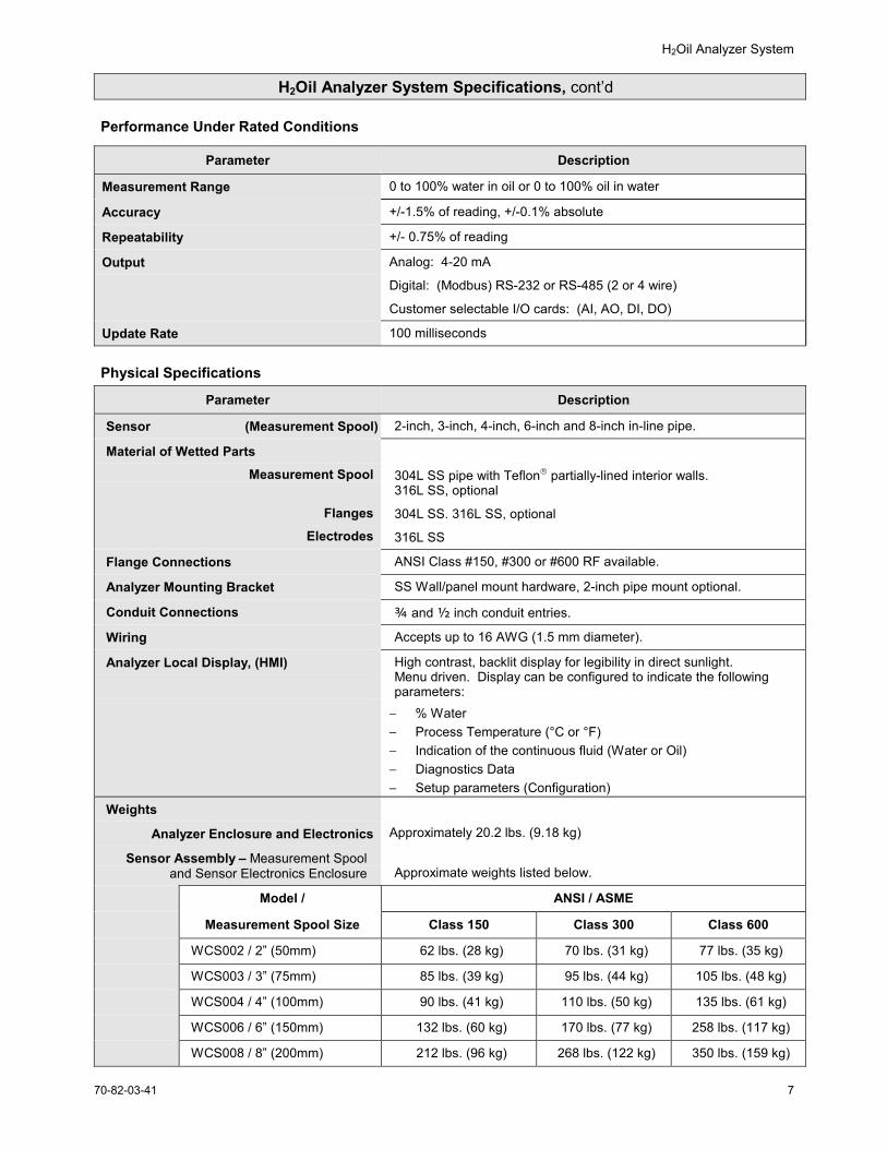
Performance Under Rated Conditions
Parameter Description
Measurement Range 0 to 100% water in oil or 0 to 100% oil in water
Accuracy +/-1.5% of reading, +/-0.1% absolute
Repeatability +/- 0.75% of reading
Output Analog: 4-20 mA
Digital: (Modbus) RS-232 or RS-485 (2 or 4 wire)
Customer selectable I/O cards: (AI, AO, DI, DO)
Update Rate 100 milliseconds Physical Specifications
Parameter Description
Sensor (Measurement Spool) 2-inch, 3-inch, 4-inch, 6-inch and 8-inch in-line pipe.
Material of Wetted PartsMeasurement Spool
FlangesElectrodes
304L SS pipe with Teflon partially-lined interior walls.316L SS, optional
304L SS. 316L SS, optional
316L SS
Flange Connections ANSI Class #150, #300 or #600 RF available.
Analyzer Mounting Bracket SS Wall/panel mount hardware, 2-inch pipe mount optional.
Conduit Connections ¾ and ½ inch conduit entries.
Wiring Accepts up to 16 AWG (1.5 mm diameter).
Analyzer Local Display, (HMI) High contrast, backlit display for legibility in direct sunlight.Menu driven. Display can be configured to indicate the followingparameters:
− % Water− Process Temperature (°C or °F)− Indication of the continuous fluid (Water or Oil)− Diagnostics Data− Setup parameters (Configuration)
Weights
Analyzer Enclosure and Electronics Approximately 20.2 lbs. (9.18 kg)
Sensor Assembly – Measurement Spooland Sensor Electronics Enclosure Approximate weights listed below.
Model / ANSI / ASME
Measurement Spool Size Class 150 Class 300 Class 600
WCS002 / 2” (50mm) 62 lbs. (28 kg) 70 lbs. (31 kg) 77 lbs. (35 kg)
WCS003 / 3” (75mm) 85 lbs. (39 kg) 95 lbs. (44 kg) 105 lbs. (48 kg)
WCS004 / 4” (100mm) 90 lbs. (41 kg) 110 lbs. (50 kg) 135 lbs. (61 kg)
WCS006 / 6” (150mm) 132 lbs. (60 kg) 170 lbs. (77 kg) 258 lbs. (117 kg)
WCS008 / 8” (200mm) 212 lbs. (96 kg) 268 lbs. (122 kg) 350 lbs. (159 kg)
H2Oil Analyzer System
70-82-03-418
H2Oil Analyzer System Specifications, cont’d
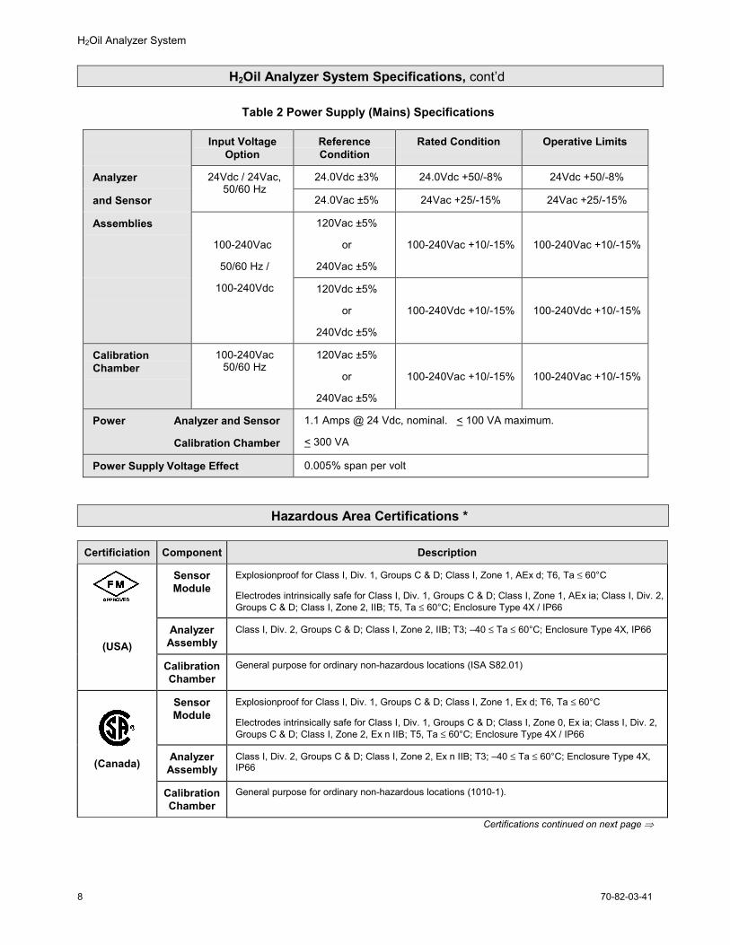
Table 2 Power Supply (Mains) Specifications
Input VoltageOption
ReferenceCondition
Rated Condition Operative Limits
Analyzer 24.0Vdc ±3% 24.0Vdc +50/-8% 24Vdc +50/-8%
and Sensor
24Vdc / 24Vac,50/60 Hz
24.0Vac ±5% 24Vac +25/-15% 24Vac +25/-15%
Assemblies 120Vac ±5%
or
240Vac ±5%
100-240Vac +10/-15% 100-240Vac +10/-15%100-240Vac
50/60 Hz /
100-240Vdc 120Vdc ±5%
or
240Vdc ±5%
100-240Vdc +10/-15% 100-240Vdc +10/-15%
CalibrationChamber
100-240Vac50/60 Hz
120Vac ±5%
or
240Vac ±5%
100-240Vac +10/-15% 100-240Vac +10/-15%
Power Analyzer and Sensor
Calibration Chamber
1.1 Amps @ 24 Vdc, nominal. < 100 VA maximum.
< 300 VA
Power Supply Voltage Effect 0.005% span per volt
Hazardous Area Certifications *
Certificiation Component Description
SensorModule
Explosionproof for Class I, Div. 1, Groups C & D; Class I, Zone 1, AEx d; T6, Ta ≤ 60°C
Electrodes intrinsically safe for Class I, Div. 1, Groups C & D; Class I, Zone 1, AEx ia; Class I, Div. 2,Groups C & D; Class I, Zone 2, IIB; T5, Ta ≤ 60°C; Enclosure Type 4X / IP66
AnalyzerAssembly
Class I, Div. 2, Groups C & D; Class I, Zone 2, IIB; T3; –40 ≤ Ta ≤ 60°C; Enclosure Type 4X, IP66
(USA)
CalibrationChamber
General purpose for ordinary non-hazardous locations (ISA S82.01)
SensorModule
Explosionproof for Class I, Div. 1, Groups C & D; Class I, Zone 1, Ex d; T6, Ta ≤ 60°C
Electrodes intrinsically safe for Class I, Div. 1, Groups C & D; Class I, Zone 0, Ex ia; Class I, Div. 2,Groups C & D; Class I, Zone 2, Ex n IIB; T5, Ta ≤ 60°C; Enclosure Type 4X / IP66
AnalyzerAssembly
Class I, Div. 2, Groups C & D; Class I, Zone 2, Ex n IIB; T3; –40 ≤ Ta ≤ 60°C; Enclosure Type 4X,IP66(Canada)
CalibrationChamber
General purpose for ordinary non-hazardous locations (1010-1).
Certifications continued on next page ⇒
H2Oil Analyzer System
70-82-03-41 9
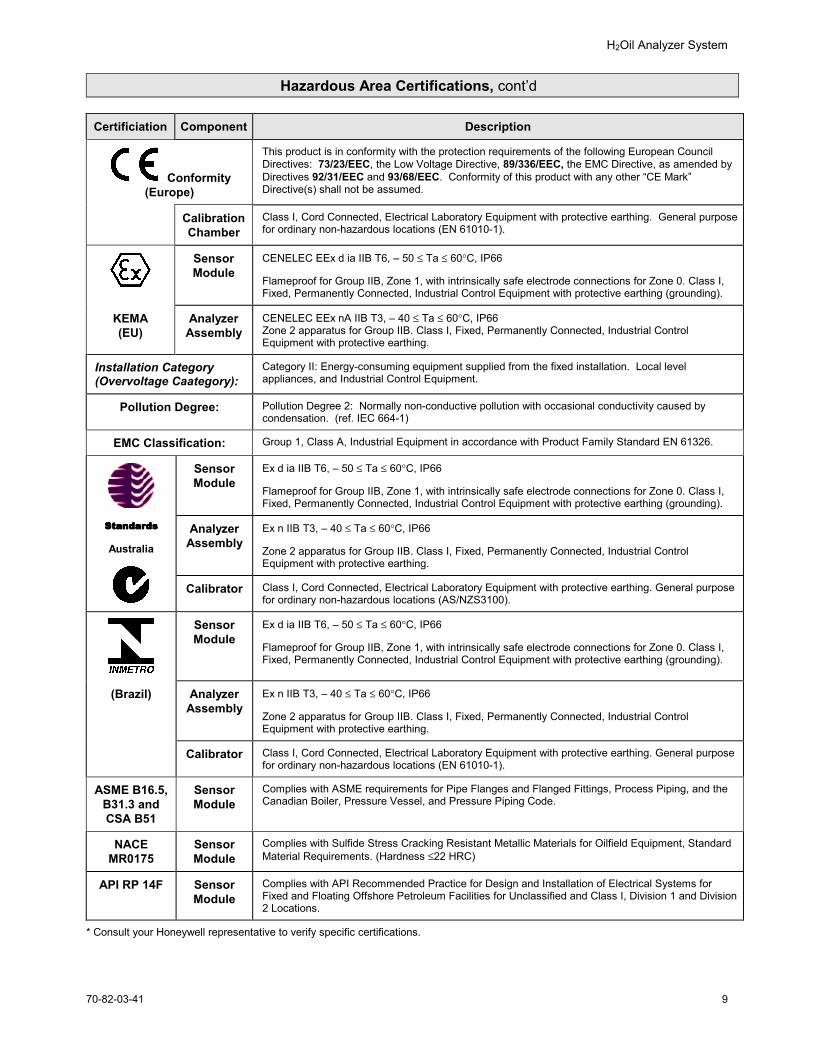
Hazardous Area Certifications, cont’d
Certificiation Component Description
Conformity(Europe)
This product is in conformity with the protection requirements of the following European CouncilDirectives: 73/23/EEC, the Low Voltage Directive, 89/336/EEC, the EMC Directive, as amended byDirectives 92/31/EEC and 93/68/EEC. Conformity of this product with any other “CE Mark”Directive(s) shall not be assumed.
CalibrationChamber
Class I, Cord Connected, Electrical Laboratory Equipment with protective earthing. General purposefor ordinary non-hazardous locations (EN 61010-1).
SensorModule
CENELEC EEx d ia IIB T6, – 50 ≤ Ta ≤ 60°C, IP66
Flameproof for Group IIB, Zone 1, with intrinsically safe electrode connections for Zone 0. Class I,Fixed, Permanently Connected, Industrial Control Equipment with protective earthing (grounding).
KEMA(EU)
AnalyzerAssembly
CENELEC EEx nA IIB T3, – 40 ≤ Ta ≤ 60°C, IP66Zone 2 apparatus for Group IIB. Class I, Fixed, Permanently Connected, Industrial ControlEquipment with protective earthing.
Installation Category(Overvoltage Caategory):
Category II: Energy-consuming equipment supplied from the fixed installation. Local levelappliances, and Industrial Control Equipment.
Pollution Degree: Pollution Degree 2: Normally non-conductive pollution with occasional conductivity caused bycondensation. (ref. IEC 664-1)
EMC Classification: Group 1, Class A, Industrial Equipment in accordance with Product Family Standard EN 61326.
SensorModule
Ex d ia IIB T6, – 50 ≤ Ta ≤ 60°C, IP66
Flameproof for Group IIB, Zone 1, with intrinsically safe electrode connections for Zone 0. Class I,Fixed, Permanently Connected, Industrial Control Equipment with protective earthing (grounding).
AnalyzerAssembly
Ex n IIB T3, – 40 ≤ Ta ≤ 60°C, IP66
Zone 2 apparatus for Group IIB. Class I, Fixed, Permanently Connected, Industrial ControlEquipment with protective earthing.
StandardsStandardsStandardsStandards
Australia
Calibrator Class I, Cord Connected, Electrical Laboratory Equipment with protective earthing. General purposefor ordinary non-hazardous locations (AS/NZS3100).
SensorModule
Ex d ia IIB T6, – 50 ≤ Ta ≤ 60°C, IP66
Flameproof for Group IIB, Zone 1, with intrinsically safe electrode connections for Zone 0. Class I,Fixed, Permanently Connected, Industrial Control Equipment with protective earthing (grounding).
(Brazil) AnalyzerAssembly
Ex n IIB T3, – 40 ≤ Ta ≤ 60°C, IP66
Zone 2 apparatus for Group IIB. Class I, Fixed, Permanently Connected, Industrial ControlEquipment with protective earthing.
Calibrator Class I, Cord Connected, Electrical Laboratory Equipment with protective earthing. General purposefor ordinary non-hazardous locations (EN 61010-1).
ASME B16.5,B31.3 andCSA B51
SensorModule
Complies with ASME requirements for Pipe Flanges and Flanged Fittings, Process Piping, and theCanadian Boiler, Pressure Vessel, and Pressure Piping Code.
NACEMR0175
SensorModule
Complies with Sulfide Stress Cracking Resistant Metallic Materials for Oilfield Equipment, StandardMaterial Requirements. (Hardness ≤22 HRC)
API RP 14F SensorModule
Complies with API Recommended Practice for Design and Installation of Electrical Systems forFixed and Floating Offshore Petroleum Facilities for Unclassified and Class I, Division 1 and Division2 Locations.
* Consult your Honeywell representative to verify specific certifications.
H2Oil Analyzer System
70-82-03-4110
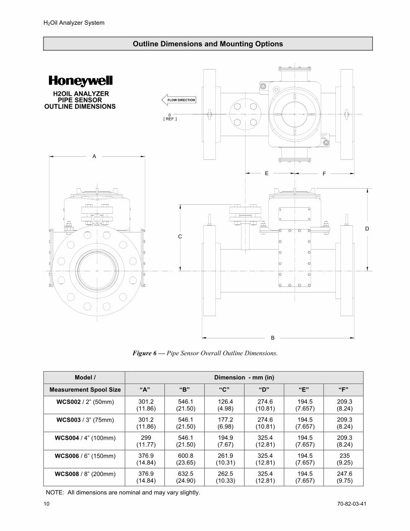
Outline Dimensions and Mounting Options
A
E F
0REF.[ ]
DC
B
FLOW DIRECTIONH2OIL ANALYZER
OUTLINE DIMENSIONSPIPE SENSOR
Figure 6 — Pipe Sensor Overall Outline Dimensions.
Model / Dimension - mm (in)
Measurement Spool Size “A” “B” “C” “D” “E” “F”
WCS002 / 2” (50mm) 301.2(11.86)
546.1(21.50)
126.4(4.98)
274.6(10.81)
194.5(7.657)
209.3(8.24)
WCS003 / 3” (75mm) 301.2(11.86)
546.1(21.50)
177.2(6.98)
274.6(10.81)
194.5(7.657)
209.3(8.24)
WCS004 / 4” (100mm) 299(11.77)
546.1(21.50)
194.9(7.67)
325.4(12.81)
194.5(7.657)
209.3(8.24)
WCS006 / 6” (150mm) 376.9(14.84)
600.8(23.65)
261.9(10.31)
325.4(12.81)
194.5(7.657)
235(9.25)
WCS008 / 8” (200mm) 376.9(14.84)
632.5(24.90)
262.5(10.33)
325.4(12.81)
194.5(7.657)
247.6(9.75)
NOTE: All dimensions are nominal and may vary slightly.
H2Oil Analyzer System
70-82-03-41 11
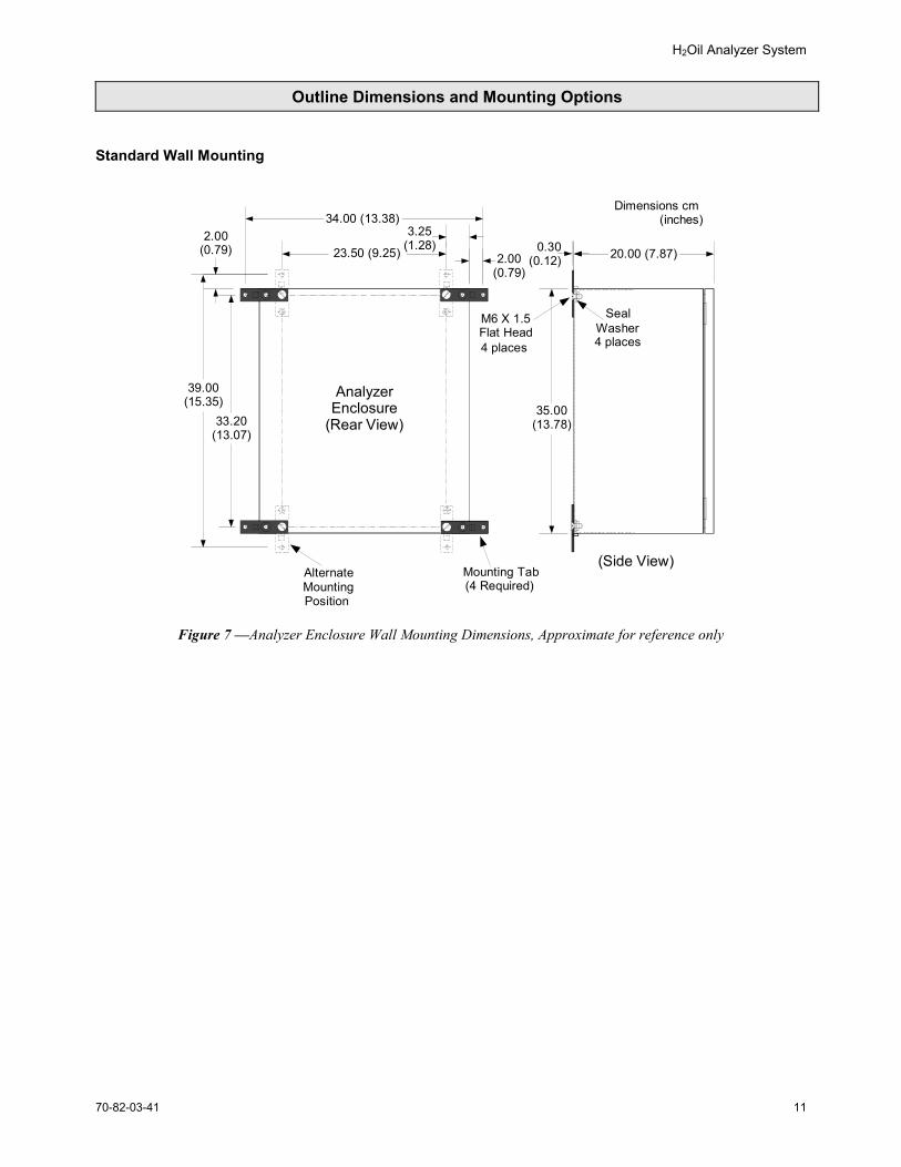
Outline Dimensions and Mounting Options
Standard Wall Mounting
34.00 (13.38)
33.20(13.07)
39.00(15.35)
3.25(1.28)
2.00(0.79)
2.00(0.79)
Mounting Tab(4 Required)
AlternateMountingPosition
AnalyzerEnclosure
(Rear View)
20.00 (7.87)
35.00(13.78)
0.30(0.12)
(Side View)
M6 X 1.5Flat Head4 places
SealWasher4 places
Dimensions cm (inches)
23.50 (9.25)
Figure 7 —Analyzer Enclosure Wall Mounting Dimensions, Approximate for reference only
H2Oil Analyzer System
70-82-03-4112
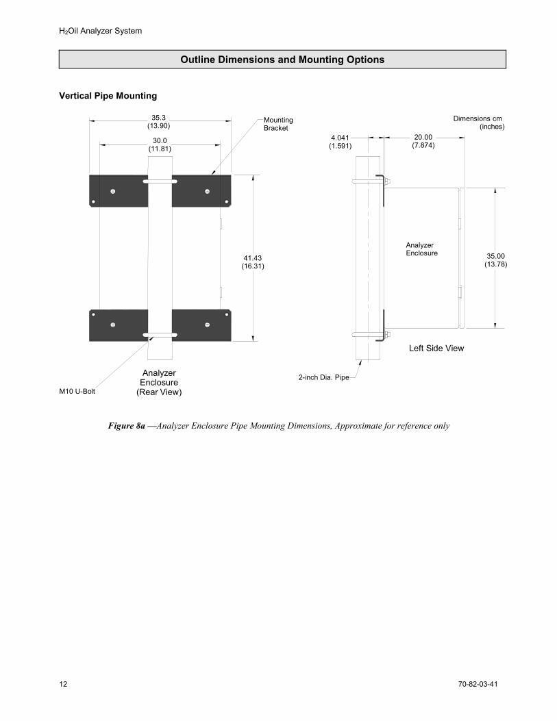
Outline Dimensions and Mounting Options
Vertical Pipe Mounting
Left Side View
20.00(7.874)
35.00(13.78)
4.041(1.591)
2-inch Dia. Pipe
AnalyzerEnclosure
Dimensions cm (inches)
41.43(16.31)
M10 U-Bolt
30.0(11.81)
AnalyzerEnclosure
(Rear View)
MountingBracket
35.3(13.90)
Figure 8a —Analyzer Enclosure Pipe Mounting Dimensions, Approximate for reference only
H2Oil Analyzer System
70-82-03-41 13
Outline Dimensions and Mounting Options
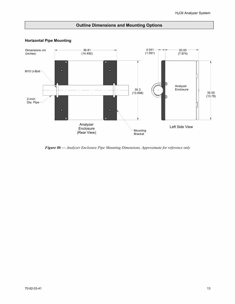
Horizontal Pipe Mounting
Left Side View
20.00(7.874)
35.00(13.78)
4.041(1.591)
AnalyzerEnclosure
2-inchDia. Pipe
MountingBracket
35.3(13.898)
M10 U-Bolt
AnalyzerEnclosure
(Rear View)
36.81(14.492)
Dimensions cm(inches)
Figure 8b — Analyzer Enclosure Pipe Mounting Dimensions, Approximate for reference only
H2Oil Analyzer System
70-82-03-4114
Model Selection Guide
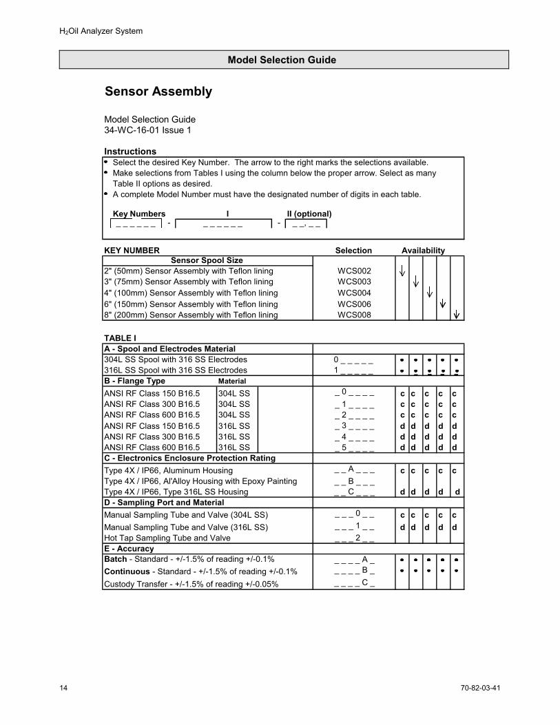
Sensor Assembly
Model Selection Guide34-WC-16-01 Issue 1
InstructionsSelect the desired Key Number. The arrow to the right marks the selections available.Make selections from Tables I using the column below the proper arrow. Select as manyTable II options as desired.A complete Model Number must have the designated number of digits in each table.
Key Numbers I II (optional)_ _ _ _ _ _ - _ _ _ _ _ _ -
KEY NUMBER Selection AvailabilitySensor Spool Size
2" (50mm) Sensor Assembly with Teflon lining WCS0023" (75mm) Sensor Assembly with Teflon lining WCS0034" (100mm) Sensor Assembly with Teflon lining WCS0046" (150mm) Sensor Assembly with Teflon lining WCS0068" (200mm) Sensor Assembly with Teflon lining WCS008
TABLE IA - Spool and Electrodes Material304L SS Spool with 316 SS Electrodes316L SS Spool with 316 SS ElectrodesB - Flange Type MaterialANSI RF Class 150 B16.5 304L SS c c c c cANSI RF Class 300 B16.5 304L SS c c c c cANSI RF Class 600 B16.5 304L SS c c c c cANSI RF Class 150 B16.5 316L SS d d d d dANSI RF Class 300 B16.5 316L SS d d d d dANSI RF Class 600 B16.5 316L SS d d d d dC - Electronics Enclosure Protection Rating Type 4X / IP66, Aluminum Housing c c c c cType 4X / IP66, Al'Alloy Housing with Epoxy Painting Type 4X / IP66, Type 316L SS Housing d d d d dD - Sampling Port and MaterialManual Sampling Tube and Valve (304L SS) c c c c cManual Sampling Tube and Valve (316L SS) d d d d dHot Tap Sampling Tube and ValveE - AccuracyBatch - Standard - +/-1.5% of reading +/-0.1% Continuous - Standard - +/-1.5% of reading +/-0.1%Custody Transfer - +/-1.5% of reading +/-0.05%
0 _ _ _ _ _ 1 _ _ _ _ _
_ 4 _ _ _ _
_ _ B _ _ __ _ A _ _ _
_ 0 _ _ _ __ 1 _ _ _ __ 2 _ _ _ __ 3 _ _ _ _
_ _ _ 0 _ _
_ 5 _ _ _ _
_ _ _ 1 _ _
_ _ _ _ A _ _ _ _ _ B _
_ _, _ _
_ _ _ _ C _
_ _ _ 2 _ _
_ _ C _ _ _
H2Oil Analyzer System
70-82-03-41 15
Model Selection Guide
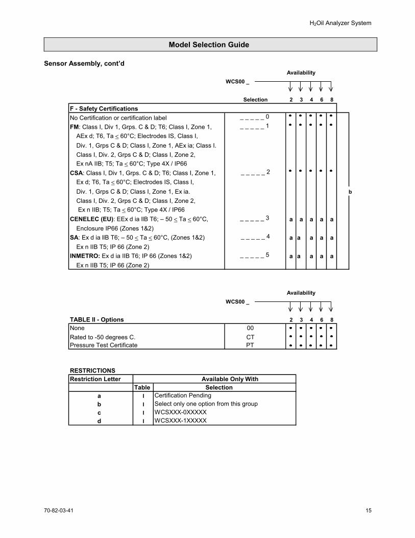
Sensor Assembly, cont’dAvailability
WCS00 _
2 3 4 6 8F - Safety CertificationsNo Certification or certification labelFM: Class I, Div 1, Grps. C & D; T6; Class I, Zone 1,
AEx d; T6, Ta < 60°C; Electrodes IS, Class I,Div. 1, Grps C & D; Class I, Zone 1, AEx ia; Class I.Class I, Div. 2, Grps C & D; Class I, Zone 2, Ex nA IIB; T5; Ta < 60°C; Type 4X / IP66
CSA: Class I, Div 1, Grps. C & D; T6; Class I, Zone 1,Ex d; T6, Ta < 60°C; Electrodes IS, Class I,Div. 1, Grps C & D; Class I, Zone 1, Ex ia. bClass I, Div. 2, Grps C & D; Class I, Zone 2, Ex n IIB; T5; Ta < 60°C; Type 4X / IP66
CENELEC (EU): EEx d ia llB T6; – 50 < Ta < 60°C, a a a a aEnclosure IP66 (Zones 1&2)
SA: Ex d ia llB T6; – 50 < Ta < 60°C, (Zones 1&2) a a a a aEx n IIB T5; IP 66 (Zone 2)
INMETRO: Ex d ia IIB T6; IP 66 (Zones 1&2) a a a a aEx n IIB T5; IP 66 (Zone 2)
AvailabilityWCS00 _
TABLE II - Options 2 3 4 6 8None 00Rated to -50 degrees C. CTPressure Test Certificate PT
RESTRICTIONSRestriction Letter Available Only With
Table Selectiona I Certification Pendingb I Select only one option from this groupc I WCSXXX-0XXXXXd I WCSXXX-1XXXXX
_ _ _ _ _ 0
_ _ _ _ _ 3
_ _ _ _ _ 4
_ _ _ _ _ 5
Selection
_ _ _ _ _ 2
_ _ _ _ _ 1
H2Oil Analyzer System
70-82-03-4116
Model Selection Guide
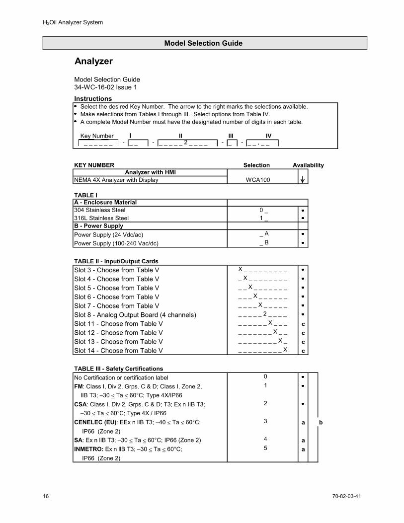
Analyzer
Model Selection Guide34-WC-16-02 Issue 1
InstructionsSelect the desired Key Number. The arrow to the right marks the selections available.Make selections from Tables I through III. Select options from Table IV.A complete Model Number must have the designated number of digits in each table.
Key Number I II III IV_ _ _ _ _ _ - _ _ - _ _ _ _ _ 2 _ _ _ _ - _ - _ _ , _ _
KEY NUMBER Selection AvailabilityAnalyzer with HMI
NEMA 4X Analyzer with Display WCA100
TABLE IA - Enclosure Material304 Stainless Steel 0 _ 316L Stainless Steel 1 _ B - Power SupplyPower Supply (24 Vdc/ac) _ A Power Supply (100-240 Vac/dc) _ B
TABLE II - Input/Output CardsSlot 3 - Choose from Table V X _ _ _ _ _ _ _ _ _
Slot 4 - Choose from Table V _ X _ _ _ _ _ _ _ _
Slot 5 - Choose from Table V _ _ X _ _ _ _ _ _ _
Slot 6 - Choose from Table V _ _ _ X _ _ _ _ _ _
Slot 7 - Choose from Table V _ _ _ _ X _ _ _ _ _
Slot 8 - Analog Output Board (4 channels) _ _ _ _ _ 2 _ _ _ _
Slot 11 - Choose from Table V _ _ _ _ _ _ X _ _ _ cSlot 12 - Choose from Table V _ _ _ _ _ _ _ X _ _ cSlot 13 - Choose from Table V _ _ _ _ _ _ _ _ X _ cSlot 14 - Choose from Table V _ _ _ _ _ _ _ _ _ X c
TABLE III - Safety CertificationsNo Certification or certification label 0FM: Class I, Div 2, Grps. C & D; Class I, Zone 2, 1
IIB T3; –30 < Ta < 60°C; Type 4X/IP66CSA: Class I, Div 2, Grps. C & D; T3; Ex n IIB T3; 2
–30 < Ta < 60°C; Type 4X / IP66CENELEC (EU): EEx n llB T3; –40 < Ta < 60°C; 3 a b
IP66 (Zone 2)SA: Ex n llB T3; –30 < Ta < 60°C; IP66 (Zone 2) 4 aINMETRO: Ex n llB T3; –30 < Ta < 60°C; 5 a
IP66 (Zone 2)
H2Oil Analyzer System
70-82-03-41 17
Model Selection Guide
Analyzer Assembly, cont’d
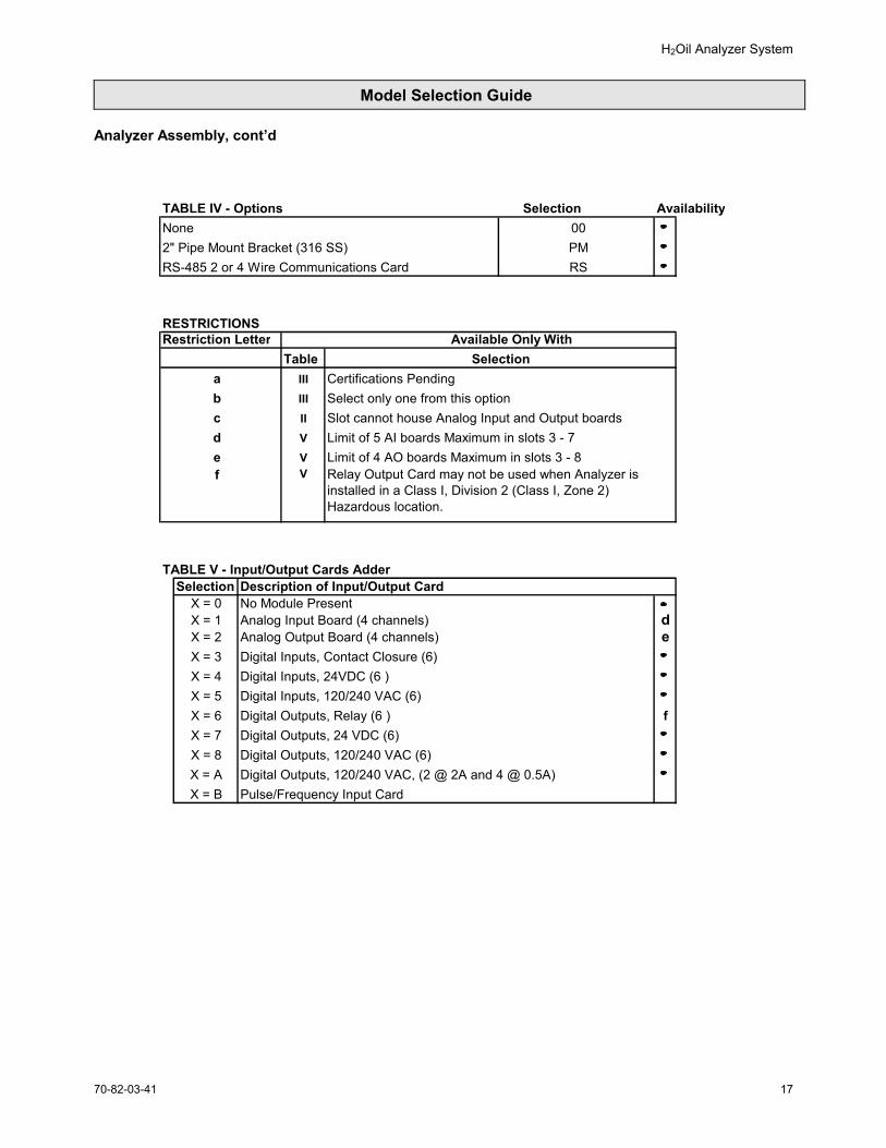
TABLE IV - Options Selection AvailabilityNone 002" Pipe Mount Bracket (316 SS) PMRS-485 2 or 4 Wire Communications Card RS
RESTRICTIONSRestriction Letter Available Only With
Tablea Certifications Pendingb Select only one from this optionc Slot cannot house Analog Input and Output boards d Limit of 5 AI boards Maximum in slots 3 - 7 e Limit of 4 AO boards Maximum in slots 3 - 8f
TABLE V - Input/Output Cards AdderSelection Description of Input/Output Card
X = 0 No Module PresentX = 1 Analog Input Board (4 channels) dX = 2 Analog Output Board (4 channels) eX = 3 Digital Inputs, Contact Closure (6)X = 4 Digital Inputs, 24VDC (6 )X = 5 Digital Inputs, 120/240 VAC (6)X = 6 Digital Outputs, Relay (6 ) fX = 7 Digital Outputs, 24 VDC (6)X = 8 Digital Outputs, 120/240 VAC (6)X = A Digital Outputs, 120/240 VAC, (2 @ 2A and 4 @ 0.5A) X = B Pulse/Frequency Input Card
Selection
Relay Output Card may not be used when Analyzer is installed in a Class I, Division 2 (Class I, Zone 2) Hazardous location.
IIIIIIII
V
VV
H2Oil Analyzer System
70-82-03-4118
Model Selection Guide
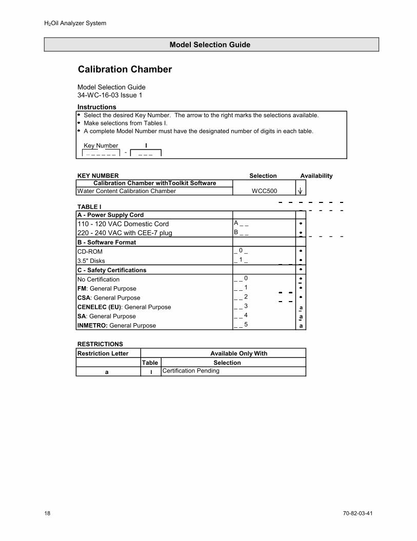
Calibration Chamber Model Selection Guide34-WC-16-03 Issue 1
InstructionsSelect the desired Key Number. The arrow to the right marks the selections available.Make selections from Tables I.A complete Model Number must have the designated number of digits in each table.
Key Number I_ _ _ _ _ _ - _ _ _
KEY NUMBER Selection AvailabilityCalibration Chamber withToolkit Software
Water Content Calibration Chamber WCC500
TABLE IA - Power Supply Cord110 - 120 VAC Domestic Cord A _ _ 220 - 240 VAC with CEE-7 plug B _ _B - Software FormatCD-ROM _ 0 _
3.5" Disks _ 1 _
C - Safety CertificationsNo Certification _ _ 0FM: General Purpose _ _ 1CSA: General Purpose _ _ 2CENELEC (EU): General Purpose _ _ 3 aSA: General Purpose _ _ 4 aINMETRO: General Purpose _ _ 5 a
RESTRICTIONSRestriction Letter Available Only With
Table Selectiona I Certification Pending
H2Oil Analyzer System
70-82-03-41 19
H2Oil Calibration Chamber and Software
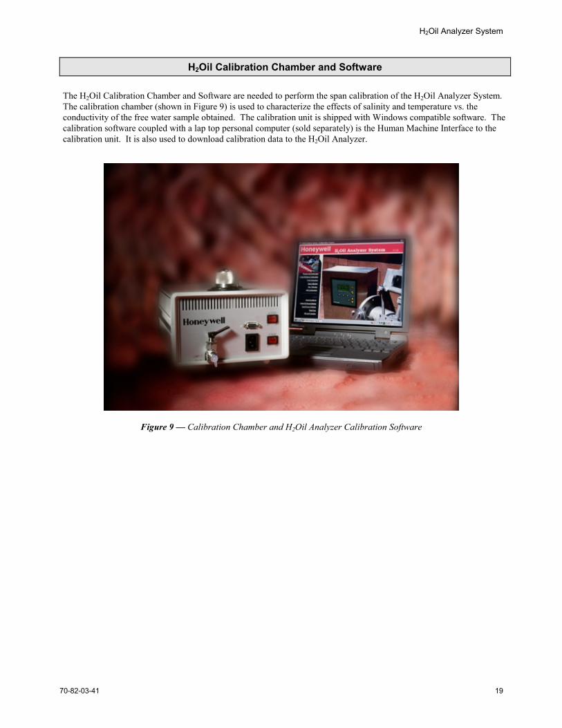
The H2Oil Calibration Chamber and Software are needed to perform the span calibration of the H2Oil Analyzer System.The calibration chamber (shown in Figure 9) is used to characterize the effects of salinity and temperature vs. theconductivity of the free water sample obtained. The calibration unit is shipped with Windows compatible software. Thecalibration software coupled with a lap top personal computer (sold separately) is the Human Machine Interface to thecalibration unit. It is also used to download calibration data to the H2Oil Analyzer.
Figure 9 — Calibration Chamber and H2Oil Analyzer Calibration Software
H2Oil Analyzer System
70-82-03-4120
Ordering Information
Contact your nearest Honeywell sales office, or
In the U.S.:Honeywell
Industrial Automation & Control16404 North Black Canyon Hwy.
Phoenix, AZ 850531-800-288-7491
In Canada:The Honeywell Centre155 Gordon Baker Rd.
North York, Ontario M2H 3N71-800-461-0013
In Latin America:Honeywell Inc.
480 Sawgrass Corporate Parkway, Suite 200
Sunrise, FL 33325(954) 845-2600
In Europe and Africa:Honeywell S. A.
Avenue du Bourget 11140 Brussels, Belgium
[32-2] 728-2111
In Eastern Europe:Honeywell Praha,
s.r.o. Budejovicka 1140 21 Prague 4,Czech Republic
In the Middle East:Honeywell Middle East Ltd.
Khalifa Street,Sheikh Faisal Building
Abu Dhabi, U. A. E.
In Asia:Honeywell Asia Pacific Inc.
Honeywell Building,17 Changi Business Park Central 1
Singapore 486073Republic of Singapore
In the Pacific:Honeywell Pty Ltd.
5 Thomas Holt DriveNorth Ryde NSW Australia 2113
(61 2) 9353 7000
In Japan:Honeywell K.K.
14-6 Shibaura 1-chromeMinato-ku, Tokyo,Japan 105-0023
Or, visit Honeywell on the World Wide Web at: http://www.honeywell.com
Distributor :
Specifications are subject to change without notice.
Industrial Automation and ControlHoneywell Inc.16404 N. Black Canyon HighwayPhoenix, AZ 85023