Embed Size (px)
Citation preview
IANGV Emission Report 3031.03.2000
3 ENGINES FOR GASEOUS FUELS
3.1 General
As mentioned in the Introduction, one could say that in general, the existing gas enginesare not as sophisticated as their gasoline or diesel fuelled counterparts. All light-duty gasengines are based on gasoline engines, and most of them are bi-fuel engines, which do nottake full advantage of the gaseous fuel.
As the supply of high-displacement gasoline engines is rather limited today, most of theheavy-duty gas engines are based on converted diesel engines. To use the original dieselengine as the base of the conversion is advantageous from the point of view ofcompatibility with the engine mountings and transmission of the vehicle. For heavy-dutyengines, robust design and long service life are expected. There are, however, also anumber of drawbacks like possible problems with higher heat rejection rates, and anengine, which from the point of view of mechanical loads is over-dimensioned.
The performance of the gas engine with respect to power output, fuel consumption andespecially exhaust emissions is highly dependent on the combustion system. Mostemission-optimised gas engines are spark-ignition engines. Pilot- or dual-fuel applications,in which gaseous fuel is fed into the intake system and ignited by diesel injection, are rarein Europe today, although there is some development work going on in Northern America/20/. Previously it was questionable whether a pilot injection gas engine could give anyreal emission benefits. Today’s advanced electronic systems might change the situation.
To improve the fuel economy of gasoline engines some manufacturers have introduceddirect injection gasoline engines. The working principle of these engines is based on timedfuel injection and a system which provides charge stratification and an ignitable mixtureclose to the spark plug /45/.
In the case of natural gas it is more difficult to arrange charge stratification and also high-pressure fuel feed in cases where the tank pressure is low.
At the moment, there is no real pressure to introduce gas direct injection for light-dutyvehicles. Due to fuel chemistry, going over from gasoline to natural gas will automaticallyreduce CO2 emissions considerably, and no increase in energy consumption is to beexpected /41/.
The situation for heavy-duty vehicles is quite different, as natural gas in a spark-ignitiongas engine replaces diesel fuel in a diesel engine. Switching to gas in this case meansincreasing the energy consumption of the vehicle by some 20-30 % /23,41,46/. Thereforesome engine manufacturers and research organisations are working on increasing theefficiency of the spark-ignited gas engine.
IANGV Emission Report 3131.03.2000
Actions which can contribute to higher engine efficiency include /19/:
• increasing the specific output (brake mean effective pressure, BMEP) of the engine• favouring lean-burn concepts over stoichiometric concepts• increasing compression ratio in combination with adaptive knock control• the use of variable valve timing and modified working cycles (Miller, Atkinson)• ultimately direct injection (especially interesting in the case of LNG)• EGR (exhaust gas recirculation)
In general, three main features or components determine the emission performance of agas engine:
• combustion system• fuel system• catalyst technology
These items will be discussed in the following. The variations in technology for light-dutyvehicles are rather small, as all current concepts are based on stoichiometric combustionand the use of a three-way-catalyst. There are, however, small variations in fuel systemtechnology. In the case of heavy-duty engines there is a broader spectrum of alternativetechnologies.
3.2 Combustion systems
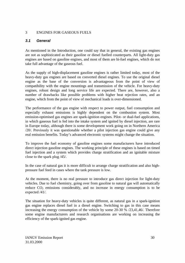
Engine-out emissions of a spark-ignition engine vary strongly with air-fuel ratio. Figure3.1 shows the general influence of air-fuel ratio on emissions of a spark-ignition engine.Relative air-fuel ratio lambda (λ) is often used to describe mixture strength. Atstoichiometry lambda is one. A λ-value less than one means that the mixture is rich, a λ-value greater than one that the mixture is lean.
All gas engines for automotive applications (cylinder diameter less than 150 mm) have anopen-type combustion chamber. Prechamber arrangements are used on larger enginesonly.
A division of spark-ignition (SI) automotive gas engines into three categories according tothe relative air-fuel ratio can be made /23/:
• stoichiometric (SM) engines (λ=1.00)• lean-burn (LB) engines (λ>1.50)• engines optimised for low fuel consumption (1.1<λ<1.3 typically).
IANGV Emission Report 3231.03.2000
Figure 3.1. Influence of air-fuel ratio on emissions and fuel consumption of a spark-ignition engine (stoichiometric means relative air/fuel ratio λ=1) /47/.
Previously, most automotive gas engines were tuned slightly lean for low fuelconsumption. This, however, resulted in very high emissions of nitrogen oxides, andtherefore such concepts cannot be used any more on new vehicles in countries withstringent exhaust gas legislation.
The stoichiometric engine is equipped with a closed-loop fuel system and a three-waycatalyst for very low exhaust emissions. The emission level of such an engine is totallydependent on the performance of the catalyst and the closed-loop fuel system.
The lean-burn engine runs on a λ value which is typically 1.5-1.6 /34/. The formation ofnitrogen oxides is controlled in the combustion process itself, by using excess air to cooldown the process.
The diesel engine is also a lean-burn engine, and the average air-fuel ratio is in the order of1.5-2.0. However, due to the heterogeneous combustion (in the flame zone λ is close toone), at a given average λ value, the diesel produces much higher emissions of nitrogenoxides. The nitrogen oxide emission level of a lean-burn gas engine is roughly 1/4…1/3 ofthat of a corresponding diesel engine /35/.
IANGV Emission Report 3331.03.2000
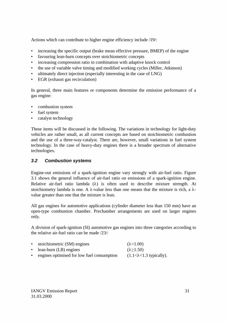
Figure 3.2 illustrates the relationship between λ, exhaust gas nitrogen oxide concentrationand thermal efficiency for a gas engine. Nitrogen oxides and also engine efficiency peaksat around λ=1.2. At λ=1.5, when the emission of nitrogen oxides has dropped to anacceptable level, engine efficiency has also gone down to a level which is close to what isachieved in stoichiometric operation (app. 36 %). When a TWC is applied usingstoichiometric mixture, nitrogen oxide emissions practically drop to zero level.
Figure 3.2. Trade-off between NOx emission and engine efficiency. Arrows show thatexhaust gas aftertreatment brings NOx concentrations down to zero level/35/.
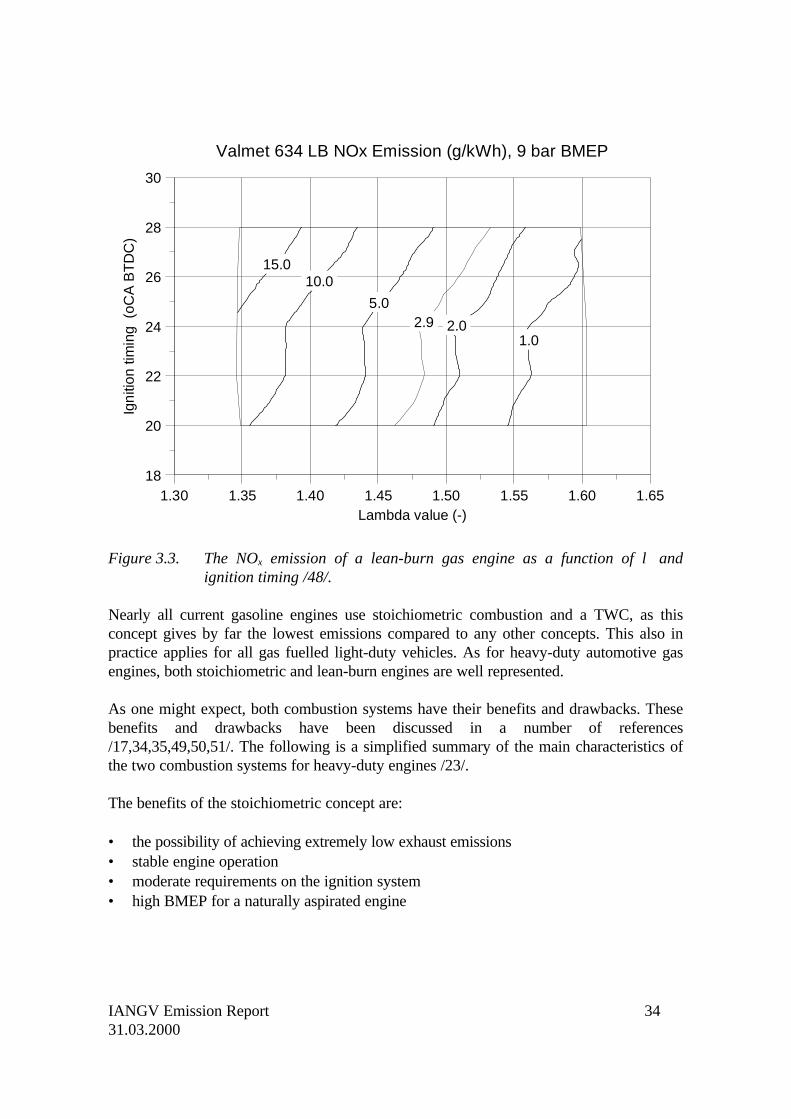
Figure 3.3 shows an example on an engine map showing the relationship between λ valueand NOx emission. It can be seen that the λ value has to be in the order of 1.5…1.55 toachieve a NOx emission below 2 g/kWh.
12
G 226-4
Effic ienc y [%]
11
10
9
8
7
6
5
4
3
2
1
033 34 35 36 37 38
Lambda=1,5p = 6,3 bare
Lambda=0,988p = 8,8 bare
NSCR catalyst i.e.three-way converter
SCR catalyst
Lambda=1,4p = 7,0 bare
Lambda=1,3p = 7,5 bare
Lambda=1,1p = 8,4 bare
Lambda=1,2p = 8,0 bare
NO
Concentratio
n
xN
O g
/m (N
TP) @
5%
Ox
2
3
IANGV Emission Report 3431.03.2000
Valmet 634 LB NOx Emission (g/kWh), 9 bar BMEP
Lambda value (-)1.30 1.35 1.40 1.45 1.50 1.55 1.60 1.65
Igni
tion
timin
g (
oCA
BT
DC
)
18
20
22
24
26
28
30
15.010.0
5.0
2.01.0
2.9
Figure 3.3. The NOx emission of a lean-burn gas engine as a function of λ andignition timing /48/.
Nearly all current gasoline engines use stoichiometric combustion and a TWC, as thisconcept gives by far the lowest emissions compared to any other concepts. This also inpractice applies for all gas fuelled light-duty vehicles. As for heavy-duty automotive gasengines, both stoichiometric and lean-burn engines are well represented.
As one might expect, both combustion systems have their benefits and drawbacks. Thesebenefits and drawbacks have been discussed in a number of references/17,34,35,49,50,51/. The following is a simplified summary of the main characteristics ofthe two combustion systems for heavy-duty engines /23/.
The benefits of the stoichiometric concept are:
• the possibility of achieving extremely low exhaust emissions• stable engine operation• moderate requirements on the ignition system• high BMEP for a naturally aspirated engine
IANGV Emission Report 3531.03.2000
The drawbacks are:
• a closed-loop fuel system and a three-way catalyst are needed for emission control• the emissions are highly dependent on the reliability of the oxygen sensor and the
control system• high thermal loadings compared to diesel or lean-burn operation• restricted possibilities for turbocharging• in some cases a fuel consumption penalty compared to lean-burn operation• not suitable for fuels with low knock resistance.
The benefits of the lean-burn concept are:
• moderate exhaust emissions• NOx formation controlled already during combustion
• high power output if turbocharging is used• thermal loading close to diesel operation.
The drawbacks are:
• turbocharging necessary to obtain sufficient power output• transient engine response• high requirements on the ignition system• high cycle-to-cycle variations• high methane emission with natural gas (unburned methane is hard to oxidise)• oxidation catalyst needed for CO and HC control.
In general, lean-burn combustion seems to be the preference of the engine manufacturers,for reasons of lower thermal loading and higher power output. The stoichiometric conceptoften requires changes in both materials and component design, i.e. modifications, whichadd to the price of the conversion.
The following list gives some examples of the preference of the engine manufacturers.
Stoichiometric combustion:
• DAF (LPG engine) /52/• Iveco /53/• MAN /54/• Mercedes-Benz /55/ (Mercedes-Benz is going to launch a new lean-burn engine)
IANGV Emission Report 3631.03.2000
Lean-burn combustion:
• Cummins /47/• Detroit Diesel /56/• Hercules /57/• Scania /58/• Volvo /59/
3.3 Fuel systems
The fuel system of a vehicle has the following main components:
• gas storage (mainly compressed natural gas, alternatively LPG or LNG)• multiple stage pressure regulation• air and fuel mixing unit or metering unit.
Normally the fuel is brought in gaseous form up to the mixing or metering unit. With LPGthere is the possibility to have the fuel as liquid up to the electrically controlled injectors ofa fuel injection system /60/. LNG would give the same opportunity.
There are two basic ways to arrange the gas supply system, i.e. mechanical or electricalfuel control. Depending on the type of the fuel systems, the gas engines can be dividedinto three categories:
1st generation: mechanical fuel metering, no feedback2nd generation: mechanical fuel metering + closed-loop electronic λ controlalternatively: fuel injection, no feedback3rd generation: fuel injection, closed-loop control
A fourth category could be added to this list, i.e. 4th generation system with OBDcapabilities (see 3.6).
A parallel to gasoline engines would be:
1st generation: carburetted2nd generation: fuel injection3rd generation: closed-loop multi-point fuel injection
The conventional way, both for light- and heavy-duty engines, is to have a venturi or asimilar mechanical device for fuel metering. In a fully mechanical fuel system, the actual λvalue will always vary with running conditions and environmental conditions, i.e. enginespeed and load, tank pressure, temperature, etc. /29/.
IANGV Emission Report 3731.03.2000
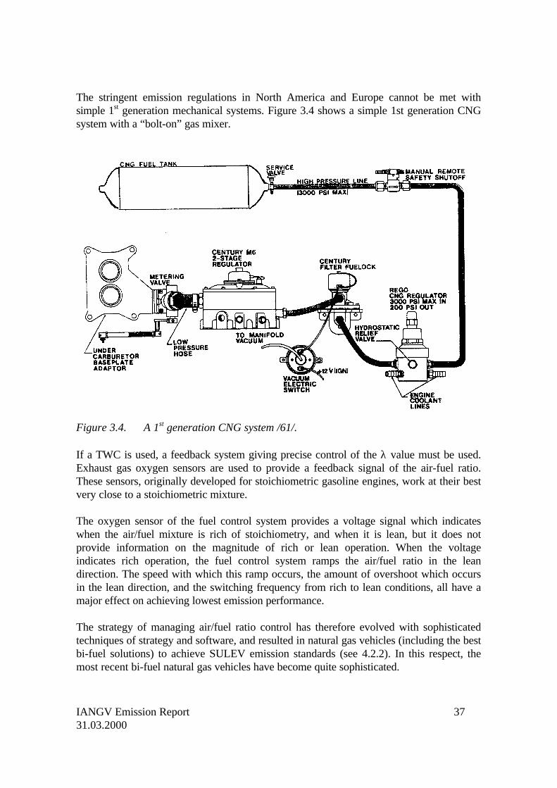
The stringent emission regulations in North America and Europe cannot be met withsimple 1st generation mechanical systems. Figure 3.4 shows a simple 1st generation CNGsystem with a “bolt-on” gas mixer.
Figure 3.4. A 1st generation CNG system /61/.
If a TWC is used, a feedback system giving precise control of the λ value must be used.Exhaust gas oxygen sensors are used to provide a feedback signal of the air-fuel ratio.These sensors, originally developed for stoichiometric gasoline engines, work at their bestvery close to a stoichiometric mixture.
The oxygen sensor of the fuel control system provides a voltage signal which indicateswhen the air/fuel mixture is rich of stoichiometry, and when it is lean, but it does notprovide information on the magnitude of rich or lean operation. When the voltageindicates rich operation, the fuel control system ramps the air/fuel ratio in the leandirection. The speed with which this ramp occurs, the amount of overshoot which occursin the lean direction, and the switching frequency from rich to lean conditions, all have amajor effect on achieving lowest emission performance.
The strategy of managing air/fuel ratio control has therefore evolved with sophisticatedtechniques of strategy and software, and resulted in natural gas vehicles (including the bestbi-fuel solutions) to achieve SULEV emission standards (see 4.2.2). In this respect, themost recent bi-fuel natural gas vehicles have become quite sophisticated.
IANGV Emission Report 3831.03.2000
Also in a lean-burn engine it is beneficial to have a closed-loop fuel system for λ control.The oxygen sensors for lean-burn operation have previously not been altogether reliable/62/. Today, however, most lean-burn engines are equipped with closed-loop fuel system.
Closed-loop control can be achieved either by adding an electronically controlled device(e.g. stepper motor operated gas valve or modulation of gas supply pressure) to a basicallymechanical fuel system (2nd generation) or by having a completely electronic fuel meteringsystem (3rd generation).
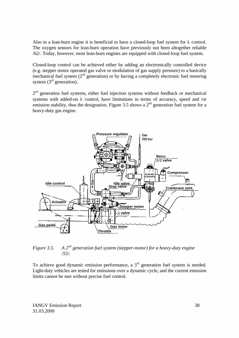
2nd generation fuel systems, either fuel injection systems without feedback or mechanicalsystems with added-on λ control, have limitations in terms of accuracy, speed and /oremission stability, thus the designation. Figure 3.5 shows a 2nd generation fuel system for aheavy-duty gas engine.
Figure 3.5. A 2nd generation fuel system (stepper-motor) for a heavy-duty engine/55/.
To achieve good dynamic emission performance, a 3rd generation fuel system is needed.Light-duty vehicles are tested for emissions over a dynamic cycle, and the current emissionlimits cannot be met without precise fuel control.
Idle control
Pressure regulator
Compressor
Stepper motor
λλ valve
ThrottleGas mixerGas pedal
Actuator
Idle valveStop valve Crankcase vent.
valve
IANGV Emission Report 3931.03.2000
In North America, the heavy-duty engines have been tested over a dynamic cycle for anumber of years. The situation in Europe will also change, as heavy-duty gas engines willbe subjected to dynamic emission testing beginning in 2000 (see 4.3). This will definitelyhave an impact on European heavy-duty gas engine technology.
Included in the category of electronically controlled fuel systems are both single- andmulti-point gas injection systems, multi-point injection systems with sequential injectionbeing “top-of-the-line”. The 3rd generation systems, which feature fully electronic control,have significantly better performance and accuracy than conventional mechanical systems.
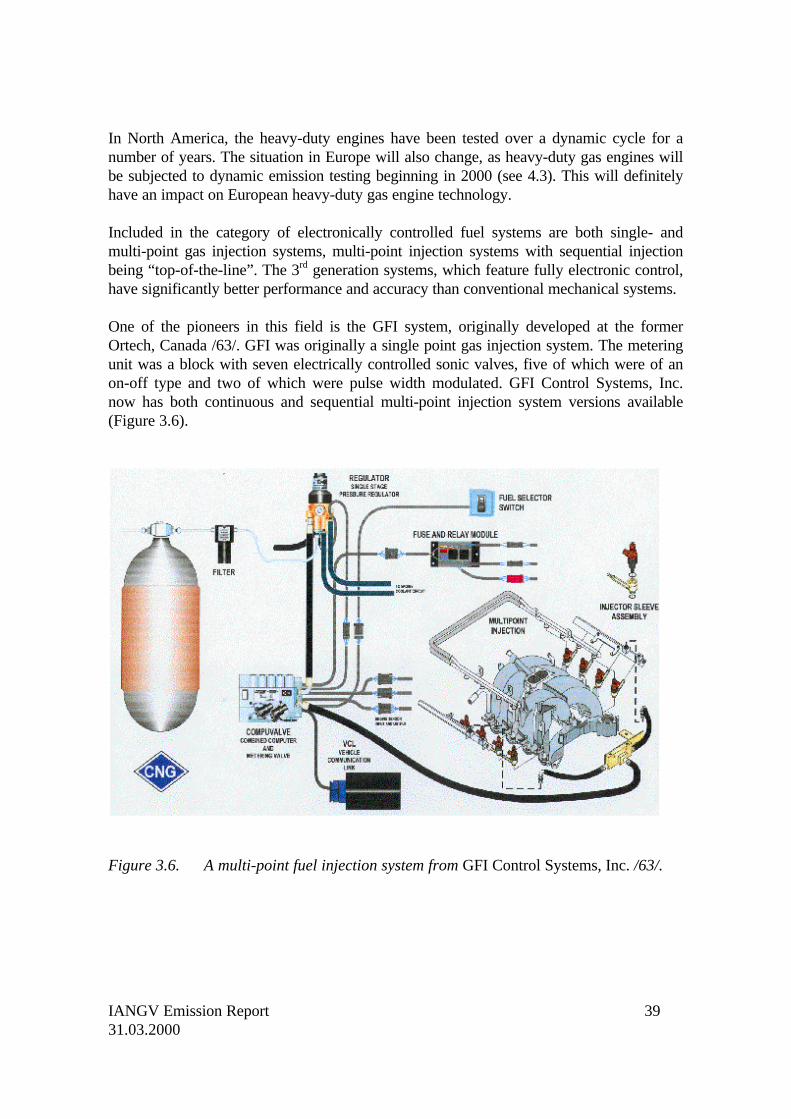
One of the pioneers in this field is the GFI system, originally developed at the formerOrtech, Canada /63/. GFI was originally a single point gas injection system. The meteringunit was a block with seven electrically controlled sonic valves, five of which were of anon-off type and two of which were pulse width modulated. GFI Control Systems, Inc.now has both continuous and sequential multi-point injection system versions available(Figure 3.6).
Figure 3.6. A multi-point fuel injection system from GFI Control Systems, Inc. /63/.
IANGV Emission Report 4031.03.2000
Several other component manufacturers, among them Gentec /64/, Koltec /65/ andTranscom /66/ (recently renamed Advanced Engine Components), also have multi-pointfuel injection systems available. Iveco uses injector components originating from Fiatpassenger cars /67/. A multi-point fuel injection gives better cylinder-to-cylinder fuelcontrol, makes it possible to use sequential fuel delivery and reduces the risk of backfire/64/. One vision of the future is that gas engines will have sequential multi-point fuelinjection, and that they will have closed-loop control for both stoichiometric and lean-burnoperation.
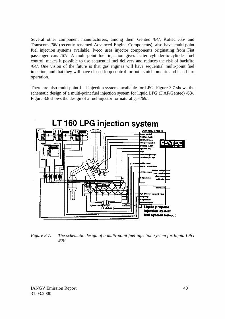
There are also multi-point fuel injection systems available for LPG. Figure 3.7 shows theschematic design of a multi-point fuel injection system for liquid LPG (DAF/Gentec) /68/.Figure 3.8 shows the design of a fuel injector for natural gas /69/.
Figure 3.7. The schematic design of a multi-point fuel injection system for liquid LPG/68/.
IANGV Emission Report 4131.03.2000
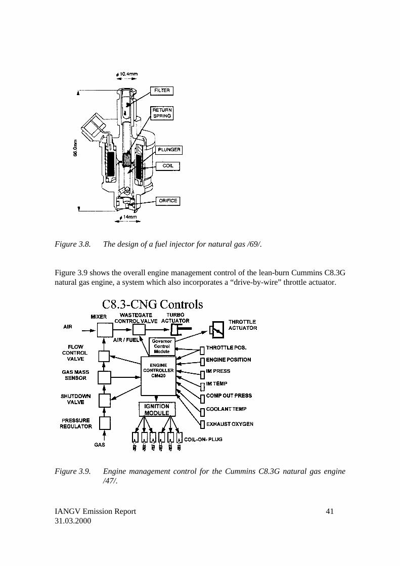
Figure 3.8. The design of a fuel injector for natural gas /69/.
Figure 3.9 shows the overall engine management control of the lean-burn Cummins C8.3Gnatural gas engine, a system which also incorporates a “drive-by-wire” throttle actuator.
Figure 3.9. Engine management control for the Cummins C8.3G natural gas engine/47/.
IANGV Emission Report 4231.03.2000
3.4 Ignition systems
Gasoline engines operating on stoichiometric mixtures set moderate requirements on theignition system and ignition energy. This is demonstrated by the fact that spark-plugreplacement intervals for modern vehicles can be up to 100,000 km. US emissionlegislation for light-duty vehicles requires spark-plug durability of at least 30 000 miles/70/.
Gasoline and LPG have roughly the same minimum ignition energy requirement.Therefore, conventional ignition systems can also handle propane, at least withstoichiometric mixtures. High ignition energy is needed with natural gas, especially withlean mixtures /34,49/. The ignition energy required in lean-burn operation can amount to150 mJ, compared to 0.25 mJ for normal stoichiometric gasoline operation.
A common problem in lean-burn operation is rapid erosion of the spark-plug electrodes.The spark plug replacement time can be as short as 300 hours /34/. Misfiring leads torough engine operation, high hydrocarbon emission and possible also to catalystoverheating.
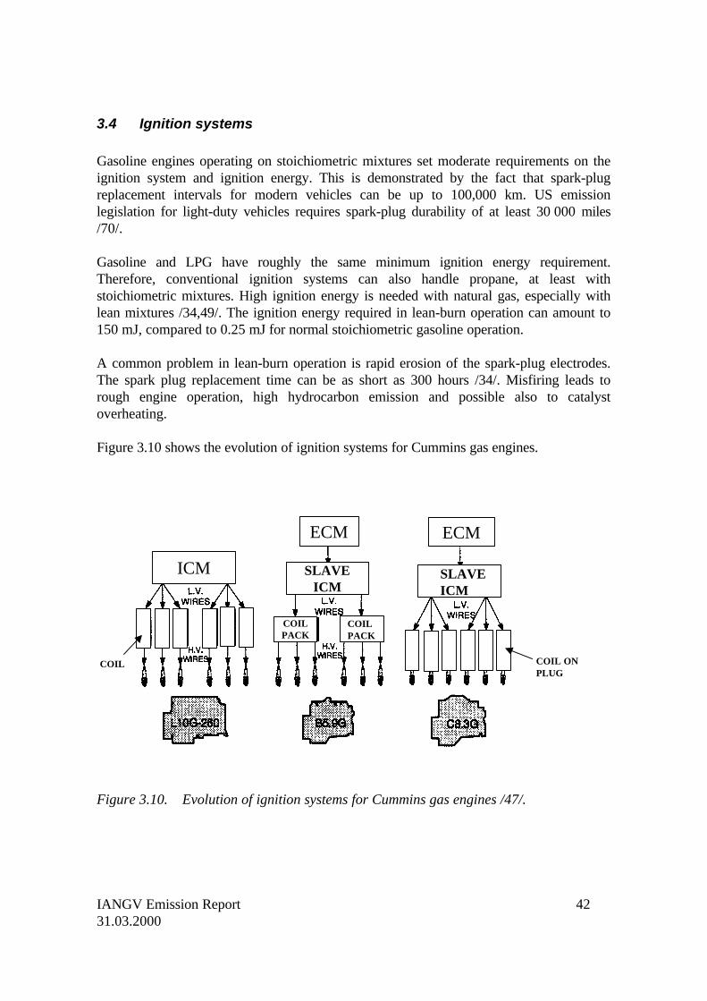
Figure 3.10 shows the evolution of ignition systems for Cummins gas engines.
Figure 3.10. Evolution of ignition systems for Cummins gas engines /47/.
COIL
ECM
ICM SLAVEICM
ECM
COILPACK
SLAVEICM
COILPACK
COIL ONPLUG
IANGV Emission Report 4331.03.2000
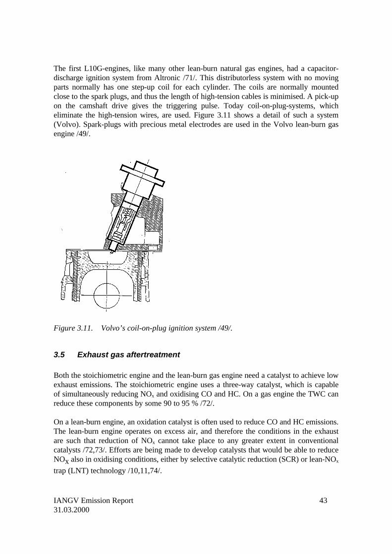
The first L10G-engines, like many other lean-burn natural gas engines, had a capacitor-discharge ignition system from Altronic /71/. This distributorless system with no movingparts normally has one step-up coil for each cylinder. The coils are normally mountedclose to the spark plugs, and thus the length of high-tension cables is minimised. A pick-upon the camshaft drive gives the triggering pulse. Today coil-on-plug-systems, whicheliminate the high-tension wires, are used. Figure 3.11 shows a detail of such a system(Volvo). Spark-plugs with precious metal electrodes are used in the Volvo lean-burn gasengine /49/.
Figure 3.11. Volvo’s coil-on-plug ignition system /49/.
3.5 Exhaust gas aftertreatment
Both the stoichiometric engine and the lean-burn gas engine need a catalyst to achieve lowexhaust emissions. The stoichiometric engine uses a three-way catalyst, which is capableof simultaneously reducing NOx and oxidising CO and HC. On a gas engine the TWC canreduce these components by some 90 to 95 % /72/.
On a lean-burn engine, an oxidation catalyst is often used to reduce CO and HC emissions.The lean-burn engine operates on excess air, and therefore the conditions in the exhaustare such that reduction of NOx cannot take place to any greater extent in conventionalcatalysts /72,73/. Efforts are being made to develop catalysts that would be able to reduceNOx also in oxidising conditions, either by selective catalytic reduction (SCR) or lean-NOx
trap (LNT) technology /10,11,74/.
IANGV Emission Report 4431.03.2000
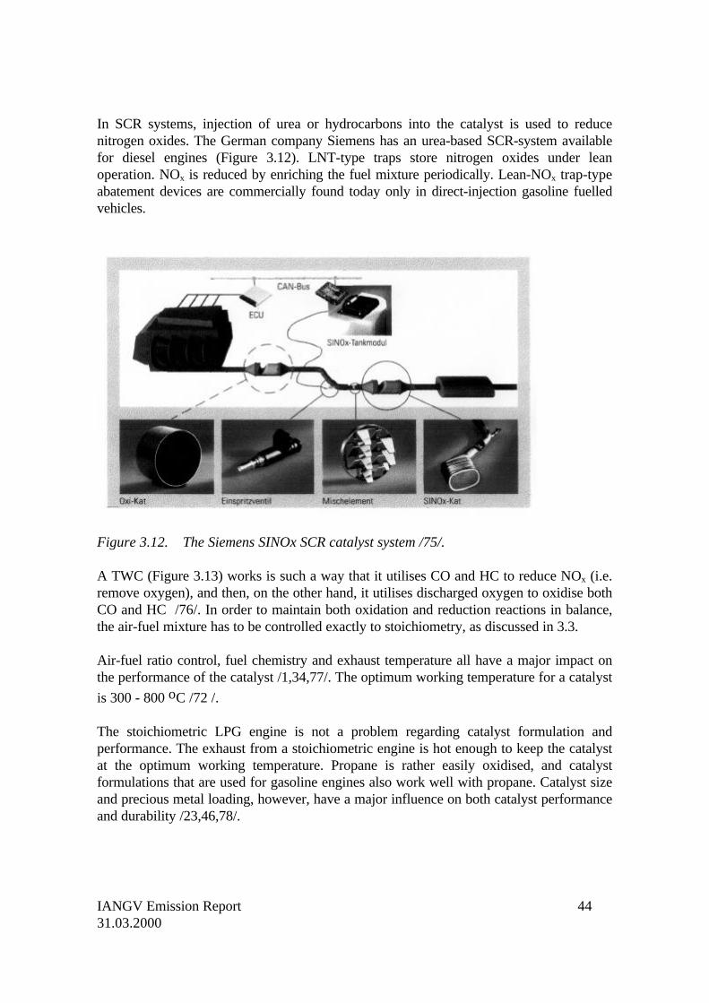
In SCR systems, injection of urea or hydrocarbons into the catalyst is used to reducenitrogen oxides. The German company Siemens has an urea-based SCR-system availablefor diesel engines (Figure 3.12). LNT-type traps store nitrogen oxides under leanoperation. NOx is reduced by enriching the fuel mixture periodically. Lean-NOx trap-typeabatement devices are commercially found today only in direct-injection gasoline fuelledvehicles.
Figure 3.12. The Siemens SINOx SCR catalyst system /75/.
A TWC (Figure 3.13) works is such a way that it utilises CO and HC to reduce NOx (i.e.remove oxygen), and then, on the other hand, it utilises discharged oxygen to oxidise bothCO and HC /76/. In order to maintain both oxidation and reduction reactions in balance,the air-fuel mixture has to be controlled exactly to stoichiometry, as discussed in 3.3.
Air-fuel ratio control, fuel chemistry and exhaust temperature all have a major impact onthe performance of the catalyst /1,34,77/. The optimum working temperature for a catalyst
is 300 - 800 oC /72 /.
The stoichiometric LPG engine is not a problem regarding catalyst formulation andperformance. The exhaust from a stoichiometric engine is hot enough to keep the catalystat the optimum working temperature. Propane is rather easily oxidised, and catalystformulations that are used for gasoline engines also work well with propane. Catalyst sizeand precious metal loading, however, have a major influence on both catalyst performanceand durability /23,46,78/.
IANGV Emission Report 4531.03.2000
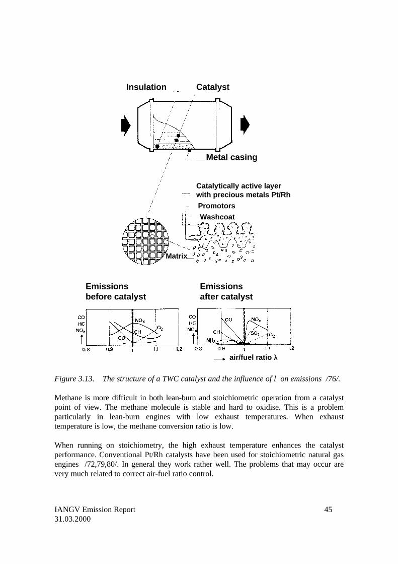
Figure 3.13. The structure of a TWC catalyst and the influence of λ on emissions /76/.
Methane is more difficult in both lean-burn and stoichiometric operation from a catalystpoint of view. The methane molecule is stable and hard to oxidise. This is a problemparticularly in lean-burn engines with low exhaust temperatures. When exhausttemperature is low, the methane conversion ratio is low.
When running on stoichiometry, the high exhaust temperature enhances the catalystperformance. Conventional Pt/Rh catalysts have been used for stoichiometric natural gasengines /72,79,80/. In general they work rather well. The problems that may occur arevery much related to correct air-fuel ratio control.
Catalyst
Metal casing
Insulation
Catalytically active layerwith precious metals Pt/Rh
Promotors
Washcoat
Matrix
Emissionsbefore catalyst
Emissionsafter catalyst
air/fuel ratio λλ
IANGV Emission Report 4631.03.2000
Figure 3.13 also shows the influence of λ on the performance of a TWC. On rich mixturesCO and HC emissions are high, on lean mixtures NOx is high, and there is a very cleartrade-off between CO and NOx /1,76/. The air-fuel ratio band within which CO, HC andNOx are simultaneously low, i.e. the conversion efficiency is high, is called the window.
Translated into emission performance of a heavy-duty gas engine the TWC catalystperformance and the CO/ NOx trade-off means that the aggregate CO + NOx sum of awell-tuned engine should be below 3 g/kWh (European ECE R49 test) /23/.
The combustion of methane produces less CO than combustion of gasoline. As CO isneeded for the reduction of NOx, the mixture has to be somewhat richer than on gasoline
for proper catalyst operation. The correct λ value for natural gas is around 0.99 /80,81/.
The λ window for proper catalyst performance is quite narrow. Ageing of the catalystboth narrows the window and increases the minimum attainable simultaneous level of COand NOx. One additional problem is that the conventional λ sensor is not very selective atthe air-fuel ratio values needed for proper operation on methane /80/.
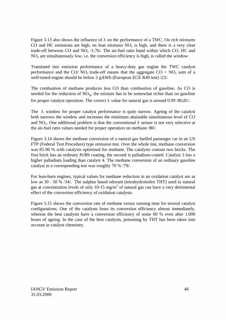
Figure 3.14 shows the methane conversion of a natural gas fuelled passenger car in an USFTP (Federal Test Procedure) type emission test. Over the whole test, methane conversionwas 85-90 % with catalysts optimised for methane. The catalysts contain two bricks. Thefirst brick has an ordinary Pt/Rh coating, the second is palladium-coated. Catalyst 3 has ahigher palladium loading than catalyst 4. The methane conversion of an ordinary gasolinecatalyst in a corresponding test was roughly 70 % /79/.
For lean-burn engines, typical values for methane reduction in an oxidation catalyst are aslow as 30 - 50 % /34/. The sulphur based odorant (tetrahydrotiofen THT) used in naturalgas at concentration levels of only 10-15 mg/m3 of natural gas can have a very detrimentaleffect of the conversion efficiency of oxidation catalysts.
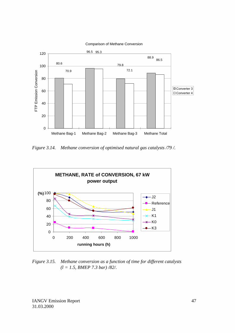
Figure 3.15 shows the conversion rate of methane versus running time for several catalystconfigurations. One of the catalysts loses its conversion efficiency almost immediately,whereas the best catalysts have a conversion efficiency of some 60 % even after 1.000hours of ageing. In the case of the best catalysts, poisoning by THT has been taken intoaccount in catalyst chemistry.
IANGV Emission Report 4731.03.2000
Figure 3.14. Methane conversion of optimised natural gas catalysts /79 /.
METHANE, RATE of CONVERSION, 67 kWpower output
0
20
40
60
80
100
0 200 400 600 800 1000
running hours (h)
(%)J2
Reference
J1
K1
K0
K3
Figure 3.15. Methane conversion as a function of time for different catalysts(λ= 1.5, BMEP 7.3 bar) /82/.
Comparison of Methane Conversion
0
20
40
60
80
100
120
Methane Bag-1 Methane Bag-2 Methane Bag-3 Methane Total
FT
P E
mis
sion
Con
vers
ion
Converter 3Converter 4
80.6
70.9
96.5 95.3
79.8
72.1
88.986.5
IANGV Emission Report 4831.03.2000
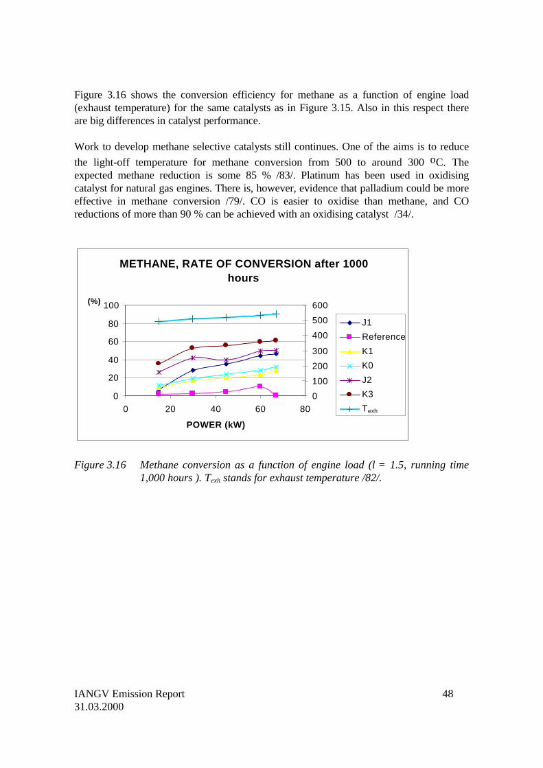
Figure 3.16 shows the conversion efficiency for methane as a function of engine load(exhaust temperature) for the same catalysts as in Figure 3.15. Also in this respect thereare big differences in catalyst performance.
Work to develop methane selective catalysts still continues. One of the aims is to reduce
the light-off temperature for methane conversion from 500 to around 300 oC. Theexpected methane reduction is some 85 % /83/. Platinum has been used in oxidisingcatalyst for natural gas engines. There is, however, evidence that palladium could be moreeffective in methane conversion /79/. CO is easier to oxidise than methane, and COreductions of more than 90 % can be achieved with an oxidising catalyst /34/.
METHANE, RATE OF CONVERSION after 1000hours
0
20
40
60
80
100
0 20 40 60 80
POWER (kW)
(%)
0
100
200
300
400
500
600
J1
Reference
K1
K0
J2
K3
Texh
Figure 3.16 Methane conversion as a function of engine load (λ= 1.5, running time1,000 hours ). Texh stands for exhaust temperature /82/.
IANGV Emission Report 4931.03.2000
3.6 OBD systems
3.6.1 General
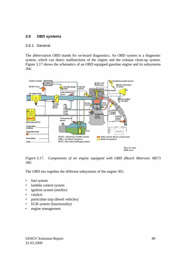
The abbreviation OBD stands for on-board diagnostics. An OBD system is a diagnosticsystem, which can detect malfunctions of the engine and the exhaust clean-up system.Figure 3.17 shows the schematics of an OBD equipped gasoline engine and its subsystems/84/.
Figure 3.17. Components of an engine equipped with OBD (Bosch Motronic ME7)/84/.
The OBD ties together the different subsystems of the engine /85/:
• fuel system• lambda control system• ignition system (misfire)• catalyst• particulate trap (diesel vehicles)• EGR system (functionality)• engine management
IANGV Emission Report 5031.03.2000
OBD systems for gasoline vehicles were originally introduced in California in 1991 (OBDI) /86/. The requirements have since been tightened, both on the State and Federal level. InEurope, OBD will be required for new gasoline vehicles beginning 2000 and for newdiesel passenger cars in 2005 /5/. In the future, OBD might also be required in heavy-dutyvehicles.
An OBD system is designed to detect adverse behaviour of the engine management systemwhich would cause emissions to increase beyond the design threshold over the useful lifeof the vehicle. The US EPA has defined the useful life of the vehicle to be 100,000 milesfor passenger cars, and 120,000 miles for light and medium duty trucks /87/.
Thresholds are currently set so that a malfunction indicator light, located in the vehicledashboard, will be illuminated if the emissions exceed 1.5 times the applicable emissionstandard. In essence, the system is an enhancement of the annual vehicle emissionsinspections carried out in many countries. The intent is to provide reliable monitoring ofthe emission control system performance on a continuous basis, so that faults can bedetected as they occur, and the vehicle will continue to provide satisfactory emissionsperformance over its useful life.
3.6.2 History of OBD
In 1991, California introduced OBD I regulations for gasoline vehicles /86,87/. The year1996 was a watershed year for alternative fuel vehicles. All alternative fuel vehicles wererequired to be equipped with OBD I systems, both California and EPA required OBD IIsystems for all fuels (but would consider annual waivers for alternative fuels), andemissions durability requirements were phased in for alternative fuel vehicles. This meantthat alternative fuel systems had to be equipped with basic diagnostic systems whichwould detect, for example, complete sensor failures. Malfunction of a sensor, such as outof range, would not require to be monitored.
The advent of OBD II systems on gasoline meant that when such a vehicle was operatedon an alternative fuel, the OBD II monitors would perceive incorrectly that a fault hadapparently occurred, and a false malfunction indicator light would be set. Some methodhad to be devised to prevent this from happening, and is discussed later.
Emissions durability requirements were largely an issue for California in 1996, sinceaftermarket conversions could continue in the 49 states under Memorandum 1A (see 3.6.5below) until the year 2000.
In 1998, Canada required OBD II systems to be fully functional on gasoline, and in 2000,Europe requires EOBD compliance for gasoline vehicles. This phase-in of OBD II typesystems is likely to continue in other countries, and it appears likely that Japan, Mexico,and other countries may require OBD II systems for gasoline vehicles by 2002/3.
IANGV Emission Report 5131.03.2000
By 2004, all OBD monitors will have to be active on all fuels, and no further waivers willbe permitted for alternative fuels. In 2005, EOBD compliance will be required onalternative fuels. This could be a major impediment to the growth of alternative fuelvehicles.
3.6.3 OBD II monitoring requirements
OBD II systems require sophisticated monitors which detect adverse behaviour in theprimary engine management system. An OBD monitor must quickly turn on themalfunction indicator light (MIL) when the engine has a fault, and must not turn on theMIL when the engine is operating properly.
Monitoring requires a decision at the end of each evaluation period to determine if theengine condition is good or bad. The decisions can either be correct or incorrect, andnoise (electrical) in the system will inevitably lead to decision errors. These errors lead toeither a false alarm, when the engine is actually operating properly, or to a failure to detectwhen a real malfunction occurs /88/.
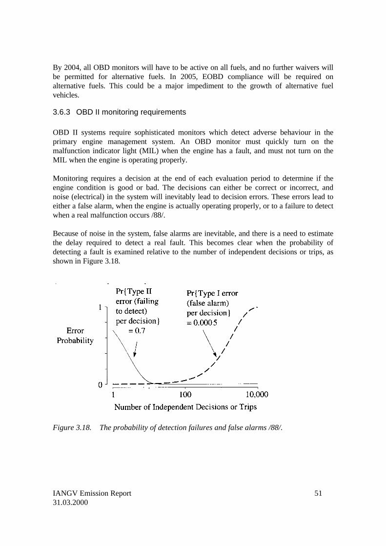
Because of noise in the system, false alarms are inevitable, and there is a need to estimatethe delay required to detect a real fault. This becomes clear when the probability ofdetecting a fault is examined relative to the number of independent decisions or trips, asshown in Figure 3.18.
Figure 3.18. The probability of detection failures and false alarms /88/.
IANGV Emission Report 5231.03.2000
A trip is defined as a set of driving conditions covering acceleration, cruise, and idle. So, atrip could be just a few km, or it could be 100 km. If the probability of failing to detect areal fault is 0.7, then over the first few trips, the probability of failing to detect a fault isquite high, but decreases with the number of trips recorded. Because of this, the MIL isusually not illuminated until at least 10 trips have been recorded, at which point theprobability is good that the error is real one. So, if the system detects a fault over the firsttrip, it will not set a warning light.
However, if it continues to detect the same fault after 10 trips, then it will set the MIL.The probability of detecting a false alarm, however, increases with the number of trips.Therefore, to avoid excessive false alarms, the probability of such errors occurring must beset very low (0.0005).
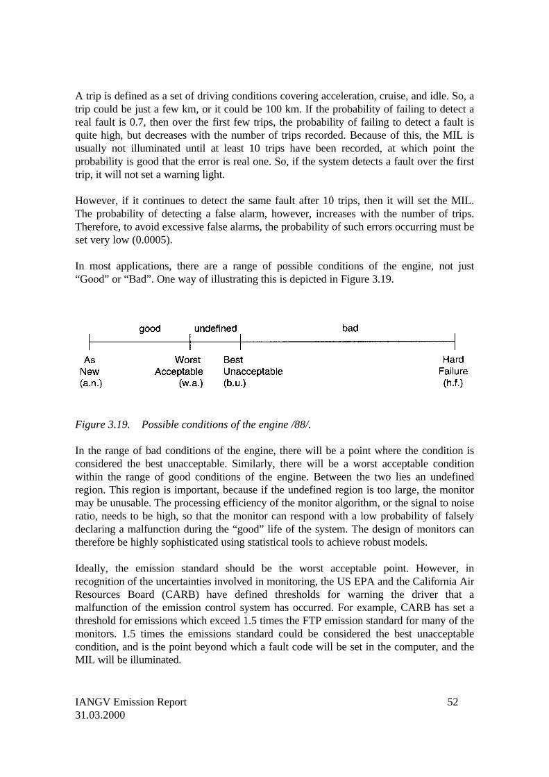
In most applications, there are a range of possible conditions of the engine, not just“Good” or “Bad”. One way of illustrating this is depicted in Figure 3.19.
Figure 3.19. Possible conditions of the engine /88/.
In the range of bad conditions of the engine, there will be a point where the condition isconsidered the best unacceptable. Similarly, there will be a worst acceptable conditionwithin the range of good conditions of the engine. Between the two lies an undefinedregion. This region is important, because if the undefined region is too large, the monitormay be unusable. The processing efficiency of the monitor algorithm, or the signal to noiseratio, needs to be high, so that the monitor can respond with a low probability of falselydeclaring a malfunction during the “good” life of the system. The design of monitors cantherefore be highly sophisticated using statistical tools to achieve robust models.
Ideally, the emission standard should be the worst acceptable point. However, inrecognition of the uncertainties involved in monitoring, the US EPA and the California AirResources Board (CARB) have defined thresholds for warning the driver that amalfunction of the emission control system has occurred. For example, CARB has set athreshold for emissions which exceed 1.5 times the FTP emission standard for many of themonitors. 1.5 times the emissions standard could be considered the best unacceptablecondition, and is the point beyond which a fault code will be set in the computer, and theMIL will be illuminated.
IANGV Emission Report 5331.03.2000
The threshold limits for setting fault codes vary with the monitor, and the standard towhich the vehicle will be certified. For example for low emission vehicles, the catalystmonitor threshold is 1.75 times the FTP standard.
3.6.4 Reaction of OBD II monitors to alternative fuels
Typically, there can be up to 10 monitors operating in OBD II systems. These are:
• Catalyst Monitor• Fuel System Monitor• Misfire Monitor• Evaporative System Monitor• Oxygen Sensor Monitor• EGR Monitor• Secondary Air System Monitor• Comprehensive Component Monitor• Thermostat Monitor• PCV Monitor
The monitors are of course designed for gasoline operation. If an OBD II equipped vehicleis operated on an alternative fuel such as propane or natural gas, for which the monitormodels are not designed, then it is likely that the monitor will sense that a fault hasoccurred, even although the vehicle may be operating correctly on the alternative fuel. Itwill therefore set a false fault code, and illuminate the MIL, when the vehicle is functioningnormally. It may not set the fault code immediately, as it checks to make sure that theerror repeats itself, and that the probability is low that the fault is a spurious one, buteventually it will recognise that the error remains (while the vehicle continues to operateon the alternative fuel), and fault codes will be set in the computer.
Reasons why exposure to alternative fuels can cause the monitors to set false codes areshown in the examples below.
Catalyst Monitor
Requirement:• Monitor the catalyst continuously for satisfactory performance once per driving cycle
Malfunction Criteria:• For low emission vehicles – 1.5 times NMOG standard

IANGV Emission Report 5431.03.2000
Alternative Fuel Issues:• Catalyst ageing will be different, and require documentation• Fuel variability will likely cause additional variability in oxygen sensor switching ratios• Unique strategies and calibrations will be required to vary switching ratio thresholds as
a function of fuel type
Fuel System Monitor
Requirement:• Monitor the fuel delivery system continuously for its ability to comply with the
emission standards
Malfunction Criteria:• 1.5 times the standard for rich and lean fuel system malfunctions
Alternative Fuel Issues:• Unique strategy/calibration will be required to allow the fuel monitor to interact with
modified fuel trim learning algorithms• High vapour generation rates and the normal interaction of the closed loop purge
strategy leaves little time to learn long term fuel trim values to allow the fuel monitorto operate efficiently.
• Stoichiometric differences resulting from fuel composition variations will add to thefuel system variability making it difficult to set thresholds for good monitoring processefficiency
Misfire Monitor
Requirement:• Monitor engine for misfire and identify the misfiring cylinder.
Malfunction Criteria:• Misfire resulting in catalyst damage• Misfire causing vehicle to exceed the standard• Misfire causing the vehicle to fails the I & M test
Alternative Fuel Issues:• Catalyst damage table must be remapped for each fuel due to differences in exhaust
temperature• Misfire startup delay times will vary with various fuels• Engine torque varies with fuel type. A unique strategy/calibration will be required for
each fuel type
IANGV Emission Report 5531.03.2000
3.6.5 OBD II compatible alternative fuel systems
General
Current OBD II regulations in the US require alternative fuel vehicles to be compliant withOBD II regulations. The MIL cannot be disabled, since this would be consideredtampering with the original emission control system, and would not comply with EPAMobile Source Enforcement Memorandum 1A.
Memo 1A provides that alterations to the vehicle will not constitute tampering if thedealer has a “reasonable basis” to believe that such acts will not adversely affect emissionsperformance when operated on the fuel for which the vehicle was originally designed.Relaying out the MIL when the vehicle is operating on the alternative fuel and enabling itwhen operating on gasoline is also not an option. Fault codes set during operation on thealternative fuel are stored in the computer and will falsely activate the MIL when thevehicle returns to gasoline operation.
However, until 2004, manufacturers of alternative fuel systems may request approval of amonitoring strategy where specific monitoring requirements are disabled for whichmonitoring may not be reliable with respect to the use of alternative fuels. This means thatselected monitors, which would otherwise set a false MIL and codes, can be disabledwhen operating on the alternative fuel. Similar regulations are emerging in Europe withEOBD systems, and it appears likely that manufacturers can apply for a derogation ofEOBD monitoring systems for which monitoring may not be reliable on alternative fuels.
It is possible, therefore, to design OBD II compatible alternative fuel systems which willbe functional to the greatest extent possible on gasoline, but will disable those monitorswhich will set false codes on the alternative fuel. Different strategies can be developeddepending on whether the alternative fuel conversion is carried out through a partnershipbetween the OEM and alternative fuel system provider, or is carried out as an aftermarketconversion. Two examples of these strategies are provided below.
OEM partnerships
In this case, the OEM and alternative fuel system provider agree to establish acommunications link between the gasoline and alternative fuel computers. The OEMflashes a special code into the gasoline computer for alternative fuel designated vehicles,which will receive and transmit message sets from the alternative fuel computer. When thevehicle starts to operate on the alternative fuel, a command is sent to the OEM computerto disable selected OBD II monitors. The vehicle now operates on the alternative fuelwithout setting false codes. When the vehicle reverts to gasoline operation, the OEMcomputer is again commanded to enable gasoline monitors to function normally.
IANGV Emission Report 5631.03.2000
Aftermarket conversions
This is more difficult to accomplish, and is very specific to each OEM system. One methodis to clear codes as they are set in the OEM computer during operation on the alternativefuel system. Communicating appropriate commands on the data bus can achieve this resultwithout the need for a special strategy in the OEM computer to allow bilateralcommunications. This type of OBD II compatible aftermarket system has been approvedby the California Air Resources Board. Since codes are cleared during alternative fueloperation, the vehicle can revert to gasoline operation without the MIL being falselyactivated, and normal OBD II monitoring continues with gasoline operation. Duringalternative fuel operation, appropriate diagnostics are provided by the alternative fuelcomputer.
3.6.6 Future of OBD systems
As the emissions standards become increasingly more stringent, catalyst efficiencies mustbe very high, and the catalyst could fail the OBD threshold even although it is still over90% efficient. This makes monitoring algorithms even more complex, and will createincreasing difficulties for alternative fuel applications.
Additional monitoring requirements are also being proposed by the regulatory bodies. Forexample, CARB is proposing a NOx threshold in addition to the current NMHCrequirement. Functional monitoring requirements are also being discussed such as “Did thevehicle achieve what the strategy commanded?”
It would appear, therefore, that the OBD systems will become sufficiently complex thatonly a close working relationship with the OEM will allow suppliers of alternative fuelconversion systems to achieve full OBD II capability.
It is still uncertain (in December 1999) how the EU directives will treat gas fuelledvehicles. Delaying the requirements for gas fuelled vehicles to 2003 or 2005 has beendiscussed. There is also the possibility of applying for derogation against the OBDrequirements through the Committee for Adaptation and Technical Progress (CATP) /89/.