Embed Size (px)
Citation preview
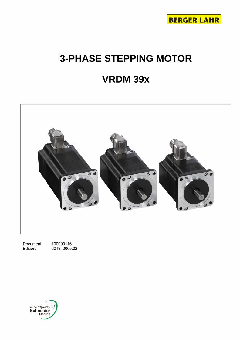
3-PHASE STEPPING MOTOR
VRDM 39x
Document: 100000116 Edition: d013, 2005.02
VRDM 39x
Document: 100000116 Edition: d013, 2005.02 www.berger-lahr.com
Data sheet stepping motor Page 1
Features common to all motor types • Test voltage to DIN EN 60034 part 1
• Insulation class F
• Run-out and perpendicularity to DIN 42955 N
• Paint: black RAL 9005
Security Please observe before installation, set-up, maintenance and repairs of the motors our security tips.
Should you not know these sheets, please ask for the data sheet “Security tips of the motors“
Motor specification The listet data in this table are motor-specified data.
A breakdown of the individual motors is given under the type code on page 10.
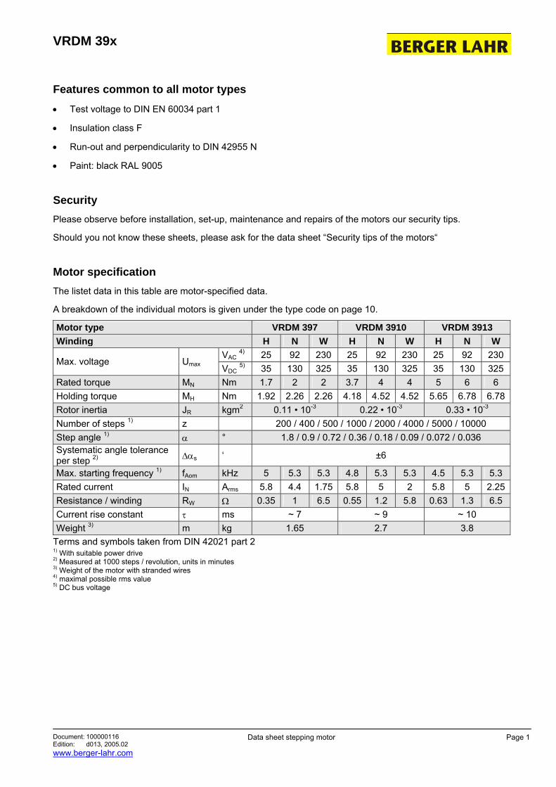
Motor type VRDM 397 VRDM 3910 VRDM 3913 Winding H N W H N W H N W
VAC 4) 25 92 230 25 92 230 25 92 230 Max. voltage Umax VDC 5) 35 130 325 35 130 325 35 130 325 Rated torque MN Nm 1.7 2 2 3.7 4 4 5 6 6 Holding torque MH Nm 1.92 2.26 2.26 4.18 4.52 4.52 5.65 6.78 6.78Rotor inertia JR kgm2 0.11 • 10-3 0.22 • 10-3 0.33 • 10-3 Number of steps 1) z 200 / 400 / 500 / 1000 / 2000 / 4000 / 5000 / 10000 Step angle 1) α ° 1.8 / 0.9 / 0.72 / 0.36 / 0.18 / 0.09 / 0.072 / 0.036 Systematic angle tolerance per step 2) ∆αs ‘ ±6
Max. starting frequency 1) fAom kHz 5 5.3 5.3 4.8 5.3 5.3 4.5 5.3 5.3 Rated current IN Arms 5.8 4.4 1.75 5.8 5 2 5.8 5 2.25Resistance / winding RW Ω 0.35 1 6.5 0.55 1.2 5.8 0.63 1.3 6.5 Current rise constant τ ms ~ 7 ~ 9 ~ 10 Weight 3) m kg 1.65 2.7 3.8
Terms and symbols taken from DIN 42021 part 2 1) With suitable power drive 2) Measured at 1000 steps / revolution, units in minutes 3) Weight of the motor with stranded wires 4) maximal possible rms value 5) DC bus voltage

VRDM 39x
Document: 100000116 Edition: d013, 2005.02 www.berger-lahr.com
Data sheet stepping motor Page 2
Characteristic curves VRDM 397
VRDM 397 / 50L H
2
1,5
1
0,5
0 fs [kHz]
n (1/min) [rpm]
10
30
0
20
J [kg cm ]2
M[Nm]
2
1.1
3
VRDM 397 / 50L N VRDM 397 / 50L W
2
1,5
1
0,5
0 fs [kHz]
n (1/min) [rpm]
10
30
0
20
J [kg cm ]2
M[Nm] 1.2
2
3
1.3
1.1 Pull-out torque Drive = D 920 UN = 35 VDC IW = 5,8 A
1.2 Pull-out torque Drive = D 900 UN = 130 VDC IW = 4,4 A
1.3 Pull-out torque Drive = WDx3-xx4, TLxx11 UN = 325 VDC IW = 1,75 A
2 Pull-in torque
3 Maximum load inertia
Measuring of characteristic curves with 1000 steps / revolution

VRDM 39x
Document: 100000116 Edition: d013, 2005.02 www.berger-lahr.com
Data sheet stepping motor Page 3
Characteristic curves VRDM 3910
VRDM 3910 / 50L H
n (1/min) [rpm]
10
30
0
20
J [kg cm ]2
4
3
2
1
0 fs [kHz]
M[Nm]
2
1.1
3
VRDM 3910 / 50L N VRDM 3910 / 50L W
n (1/min) [rpm]
10
30
0
20
J [kg cm ]2
4
3
2
1
0 fs [kHz]
M[Nm]1.2
2
3
1.3
1.1 Pull-out torque Drive = D 920 UN = 35 VDC IW = 5,8 A
1.2 Pull-out torque Drive = D 900 UN = 130 VDC IW = 5 A
1.3 Pull-out torque Drive = WDx3-xx4, TLxx11 UN = 325 VDC IW = 2 A
2 Pull-in torque
3 Maximum load inertia
Measuring of characteristic curves with 1000 steps / revolution
VRDM 39x
Document: 100000116 Edition: d013, 2005.02 www.berger-lahr.com
Data sheet stepping motor Page 4
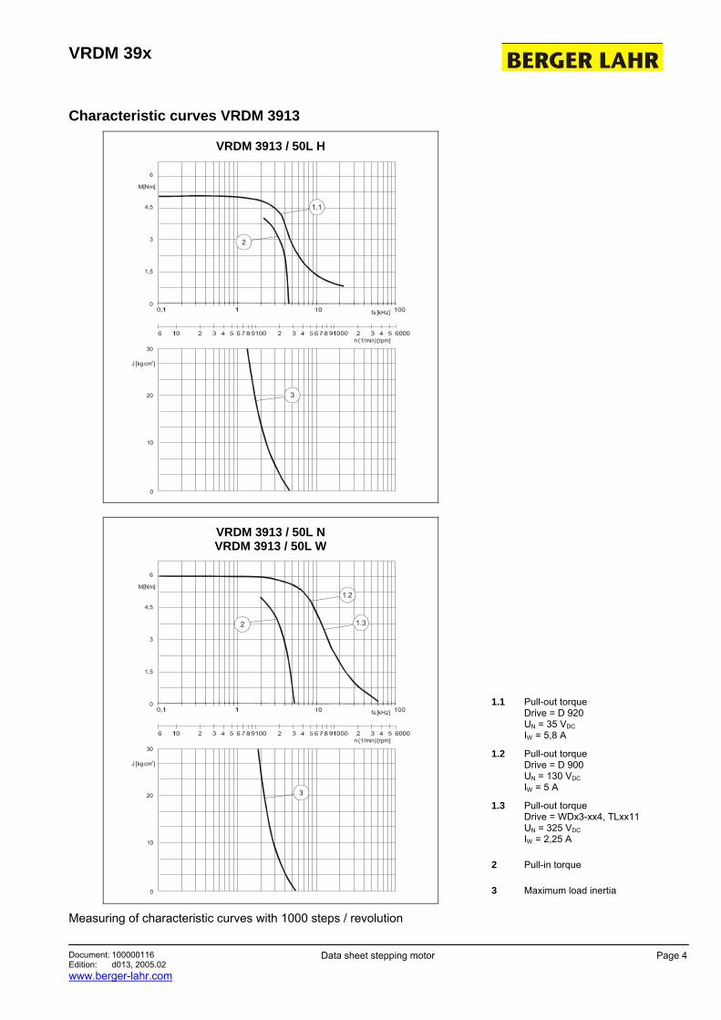
Characteristic curves VRDM 3913
VRDM 3913 / 50L H
6
4,5
3
1,5
0 fs [kHz]
n (1/min) [rpm]
10
30
0
20
J [kg cm ]2
M[Nm]
2
1.1
3
VRDM 3913 / 50L N VRDM 3913 / 50L W
6
4,5
3
1,5
0 fs [kHz]
n (1/min) [rpm]
10
30
0
20
J [kg cm ]2
M[Nm]
2
1.2
3
1.3
1.1 Pull-out torque Drive = D 920 UN = 35 VDC IW = 5,8 A
1.2 Pull-out torque Drive = D 900 UN = 130 VDC IW = 5 A
1.3 Pull-out torque Drive = WDx3-xx4, TLxx11 UN = 325 VDC IW = 2,25 A
2 Pull-in torque
3 Maximum load inertia
Measuring of characteristic curves with 1000 steps / revolution
VRDM 39x
Document: 100000116 Edition: d013, 2005.02 www.berger-lahr.com
Data sheet stepping motor Page 5
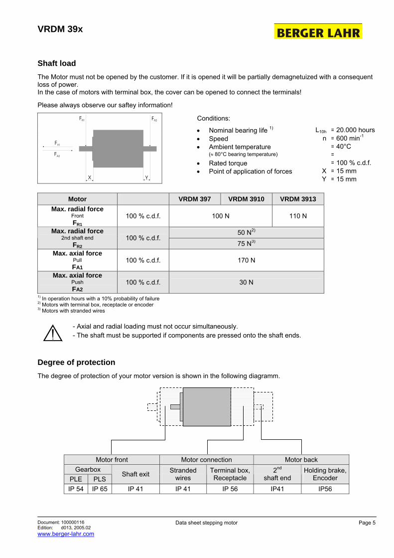
Shaft load The Motor must not be opened by the customer. If it is opened it will be partially demagnetuized with a consequent loss of power. In the case of motors with terminal box, the cover can be opened to connect the terminals!
Please always observe our saftey information!
Conditions:
• Nominal bearing life 1) L10h = 20.000 hours • Speed n = 600 min-1 • Ambient temperature = 40°C (≈ 80°C bearing temperature) = • Rated torque = 100 % c.d.f. • Point of application of forces X = 15 mm
X Y
FA1
FA2
FR2FR1
Y = 15 mm
Motor VRDM 397 VRDM 3910 VRDM 3913 Max. radial force
Front FR1
100 % c.d.f. 100 N 110 N
50 N2) Max. radial force 2nd shaft end
FR2 100 % c.d.f.
75 N3) Max. axial force
Pull FA1
100 % c.d.f. 170 N
Max. axial force Push FA2
100 % c.d.f. 30 N
1) In operation hours with a 10% probability of failure 2) Motors with terminal box, receptacle or encoder 3) Motors with stranded wires
- Axial and radial loading must not occur simultaneously. - The shaft must be supported if components are pressed onto the shaft ends.
Degree of protection The degree of protection of your motor version is shown in the following diagramm.
Motor front Motor connection Motor back Gearbox
PLE PLS Shaft exit Stranded
wires Terminal box,Receptacle
2nd shaft end
Holding brake,Encoder
IP 54 IP 65 IP 41 IP 41 IP 56 IP41 IP56
VRDM 39x
Document: 100000116 Edition: d013, 2005.02 www.berger-lahr.com
Data sheet stepping motor Page 6
Ambient conditions
Climate: (with reference to DIN 50019-R14)
Temperature (t): -25°C to +40°C Atmospheric humidity (U): ≤ 75 % RH annual average / 95 % RH on 30 days / without condensation
Storage and transportation temperature: -25°C to +70°C
Motor service life Where motors are operated under technically correct conditions, the service life is largely depend on the service life of the bearing. The following operating conditions may significantly reduce the service life of the motor:
• Installation at altitudes over 1000 m above mean sea level
• Continuous operating temperatures greater than 80°C
• Angular travel less than 100°
• Operation with very high rotation accelerations
• Operation und vibration loads greater than 20 m/s²
• High cyclic frequencies
• Running with dry sealing rings
• Wetting seals with aggressive media
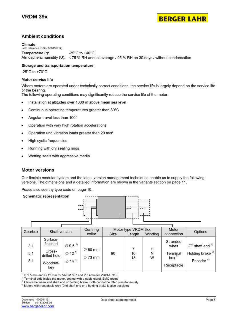
Motor versions Our flexible modular system and the latest version management techniques enable us to supply the following versions. The dimensions and a detailed information are shown in the variants section on page 11.
Pease also see thy type code on page 10.
Schematic representation
Motor type VRDM 3xx Gearbox Shaft version Centring collar Size Length Winding
Motor connection Options
3:1
5:1
8:1
Surface-finished
Cross-drilled hole
Woodruff-key
∅ 9,5 1)
∅ 12 1)
∅ 14 1)
∅ 60 mm
∅ 73 mm 90
7 10 13
H N W
Stranded wires
Terminal box 2)
Receptacle
2nd shaft end 3)
Holding brake 3)
Encoder 4)
1) ∅ 9.5 mm and ∅ 12 mm for VRDM 397 and ∅ 14mm for VRDM 3913 2) Terminal strip inside the motor, sealed with a cable gland, EMC-tested 3) Choice between 2nd shaft end or holding brake. Both cannot be fitted simultaneously 4) Motors with receptacle only (2nd shaft end or a holding brake is also possible)
VRDM 39x
Document: 100000116 Edition: d013, 2005.02 www.berger-lahr.com
Data sheet stepping motor Page 7
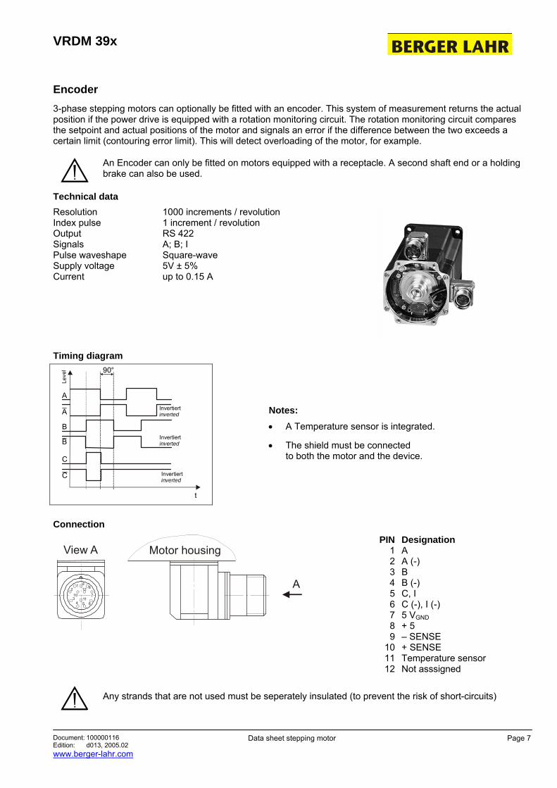
Encoder 3-phase stepping motors can optionally be fitted with an encoder. This system of measurement returns the actual position if the power drive is equipped with a rotation monitoring circuit. The rotation monitoring circuit compares the setpoint and actual positions of the motor and signals an error if the difference between the two exceeds a certain limit (contouring error limit). This will detect overloading of the motor, for example.
An Encoder can only be fitted on motors equipped with a receptacle. A second shaft end or a holding brake can also be used.
Technical data Resolution Index pulse Output Signals Pulse waveshape Supply voltage Current
1000 increments / revolution 1 increment / revolution RS 422 A; B; I Square-wave 5V ± 5% up to 0.15 A
Timing diagram 90°
A
Leve
l
B
A
C
C
B
t
Invertiertinverted
Invertiertinverted
Invertiertinverted
Notes: • A Temperature sensor is integrated.
• The shield must be connected to both the motor and the device.
Connection
Motor housing
1 98
7
6
12
1154
3
210
A
View A
PIN 1 2 3 4 5 6 7 8 9
10 11 12
Designation A A (-) B B (-) C, I C (-), I (-) 5 VGND + 5 – SENSE + SENSE Temperature sensor Not asssigned
Any strands that are not used must be seperately insulated (to prevent the risk of short-circuits)
VRDM 39x
Document: 100000116 Edition: d013, 2005.02 www.berger-lahr.com
Data sheet stepping motor Page 8
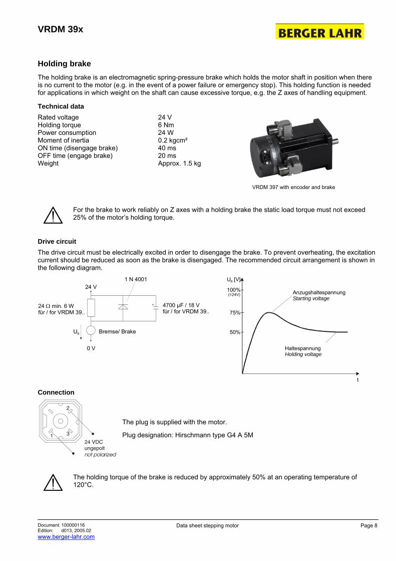
Holding brake The holding brake is an electromagnetic spring-pressure brake which holds the motor shaft in position when there is no current to the motor (e.g. in the event of a power failure or emergency stop). This holding function is needed for applications in which weight on the shaft can cause excessive torque, e.g. the Z axes of handling equipment.
Technical data
Rated voltage Holding torque Power consumption Moment of inertia ON time (disengage brake) OFF time (engage brake) Weight
24 V 6 Nm 24 W 0.2 kgcm² 40 ms 20 ms Approx. 1.5 kg
VRDM 397 with encoder and brake
For the brake to work reliably on Z axes with a holding brake the static load torque must not exceed 25% of the motor’s holding torque.
Drive circuit The drive circuit must be electrically excited in order to disengage the brake. To prevent overheating, the excitation current should be reduced as soon as the brake is disengaged. The recommended circuit arrangement is shown in the following diagram.
24 V1 N 4001
UB
0 V
+
Bremse/ Brake
4700 µF / 18 Vfür / for VRDM 39..
24 min. 6 W für / for VRDM 39..
Ω
100%
75%
U [V]B
50%
t
(=24V) AnzugshaltespannungStarting voltage
HaltespannungHolding voltage
Connection
The plug is supplied with the motor.
Plug designation: Hirschmann type G4 A 5M
The holding torque of the brake is reduced by approximately 50% at an operating temperature of 120°C.
VRDM 39x
Document: 100000116 Edition: d013, 2005.02 www.berger-lahr.com
Data sheet stepping motor Page 9
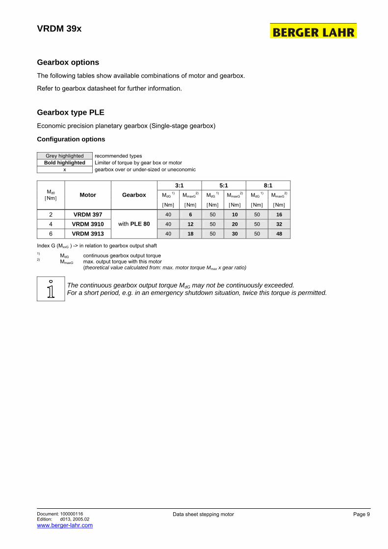
Gearbox options The following tables show available combinations of motor and gearbox.
Refer to gearbox datasheet for further information.
Gearbox type PLE Economic precision planetary gearbox (Single-stage gearbox)
Configuration options
Grey highlighted recommended types Bold highlighted Limiter of torque by gear box or motor
x gearbox over or under-sized or uneconomic
3:1 5:1 8:1 MdG
1) MmaxG2) MdG
1) MmaxG2) MdG
1) MmaxG2) Md0
[Nm] Motor Gearbox [Nm] [Nm] [Nm] [Nm] [Nm] [Nm]
2 VRDM 397 40 6 50 10 50 16
4 VRDM 3910 40 12 50 20 50 32
6 VRDM 3913 with PLE 80
40 18 50 30 50 48
Index G (MxxG ) -> in relation to gearbox output shaft 1) MdG continuous gearbox output torque 2) MmaxG max. output torque with this motor (theoretical value calculated from: max. motor torque Mmax x gear ratio)
The continuous gearbox output torque MdG may not be continuously exceeded. For a short period, e.g. in an emergency shutdown situation, twice this torque is permitted.
VRDM 39x
Document: 100000116 Edition: d013, 2005.02 www.berger-lahr.com
Data sheet stepping motor Page 10
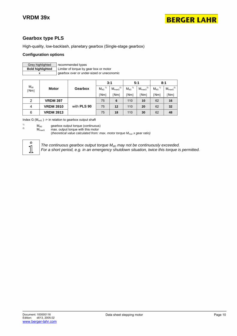
Gearbox type PLS High-quality, low-backlash, planetary gearbox (Single-stage gearbox)
Configuration options
Grey highlighted recommended types Bold highlighted Limiter of torque by gear box or motor
x gearbox over or under-sized or uneconomic
3:1 5:1 8:1 MdG
1) MmaxG2) MdG
1) MmaxG2) MdG
1) MmaxG2) Md0
[Nm] Motor Gearbox [Nm] [Nm] [Nm] [Nm] [Nm] [Nm]
2 VRDM 397 75 6 110 10 62 16
4 VRDM 3910 75 12 110 20 62 32
6 VRDM 3913 with PLS 90
75 18 110 30 62 48
Index G (MxxG ) -> in relation to gearbox output shaft 1) MdG gearbox output torque (continuous) 2) MmaxG max. output torque with this motor (theoretical value calculated from: max. motor torque Mmax x gear ratio)
The continuous gearbox output torque MdG may not be continuously exceeded. For a short period, e.g. in an emergency shutdown situation, twice this torque is permitted.
VRDM 39x
Document: 100000116 Edition: d013, 2005.02 www.berger-lahr.com
Data sheet stepping motor Page 11
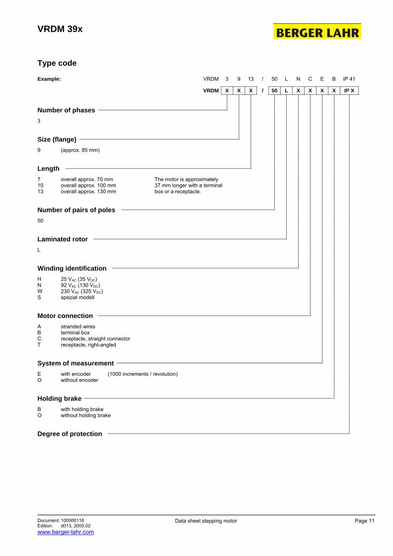
Type code
Example: VRDM 3 9 13 / 50 L N C E B IP 41
VRDM X X X / 50 L X X X X IP X
Number of phases 3
Size (flange) 9 (approx. 85 mm)
Length 7 overall approx. 70 mm The motor is approximately 10 overall approx. 100 mm 37 mm longer with a terminal 13 overall approx. 130 mm box or a receptacle.
Number of pairs of poles
50
Laminated rotor L
Winding identification H 25 VAC (35 VDC) N 92 VAC (130 VDC) W 230 VAC (325 VDC) S spezial modell
Motor connection
A stranded wires B terminal box C receptacle, straight connector T receptacle, right-angled
System of measurement
E with encoder (1000 increments / revolution) O without encoder
Holding brake
B with holding brake O without holding brake
Degree of protection
VRDM 39x
Document: 100000116 Edition: d013, 2005.02 www.berger-lahr.com
Data sheet stepping motor Page 12
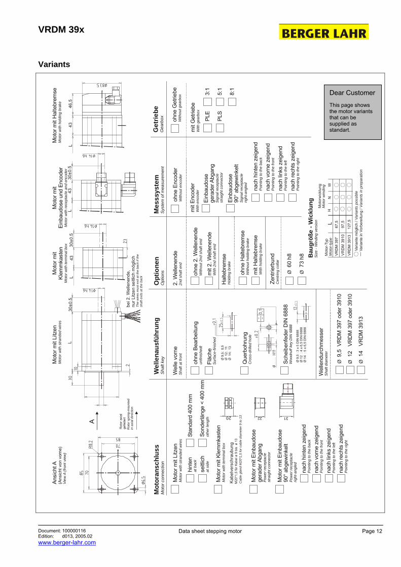
Variants
Ø 9
,5 :
3 x
5 D
IN 6
888
Ø 1
2 :
4 x
6,5
DIN
688
8Ø
14
: 5
x 6,
5 D
IN 6
888
A
Rot
or s
prin
g-m
ount
edin
axi
al d
irect
ion
Rot
or a
xial
gefe
dert
Cab
le g
land
M20
*1,5
for c
able
dia
met
er 9
to 1
3
Kab
elve
rsch
raub
ung
M20
*1,5
für K
abel
ø 9
bis
ø 1
3
20
Mot
or m
it Kl
emm
kast
enM
otor
with
term
inal
box
Mot
or m
it Ei
nbau
dose
gera
der A
bgan
gPo
wer
rece
ptac
lest
raig
ht c
onne
ctor
Mot
oran
schl
uss
Mot
or c
onne
ctio
nM
esss
yste
mS
yste
m o
f mea
sure
men
t
ohne
Enc
oder
With
out e
ncod
er
mit
Enco
der
With
enc
oder
Einb
audo
sege
rade
r Abg
ang
Sig
nal r
ecep
tacl
est
raig
ht c
onne
ctor
Ein
baud
ose
90°
abge
win
kelt
Sign
al re
cept
acle
right
-ang
led
Opt
ione
nO
ptio
nsG
etrie
beG
earb
ox
2. W
elle
nend
e2n
d sh
aft e
ndoh
ne G
etrie
beW
ithou
t gea
rbox
3:1
Mot
or m
it Ei
nbau
dose
90° a
bgew
inke
ltPo
wer
rece
ptac
lerig
ht-a
ngle
d
22
mit
Get
riebe
With
gea
rbox
5:1
8:1
Mot
or m
it Li
tzen
Mot
or w
ith s
trand
ed w
ires
hint
enat
bac
k
seitl
ich
at s
ide
Stan
dard
400
mm
Sond
erlä
nge
< 40
0 m
mot
her l
engt
h
Wel
lena
usfü
hrun
gSh
aft k
ey
Fläc
heSu
rface
-fini
shed
Que
rboh
rung
Cro
ss-d
rille
d ho
le
Sche
iben
fede
r DIN
688
8W
oodr
uff k
ey D
IN 6
888
ohne
Bea
rbei
tung
unfin
ishe
dtoh
ne 2
. Wel
lene
nde
With
out 2
nd s
haft
end
mit
2. W
elle
nend
eW
ith 2
nd s
haft
end
Zent
rierb
und
Cen
tring
col
lar
Ø 6
0 h8
Ø 7
3 h8
Wel
lend
urch
mes
ser
Sha
ft di
amet
er
Ø 9
,5 V
RD
M 3
97 o
der 3
910
Ø 1
2 V
RD
M 3
97 o
der 3
910
Ø 1
4 V
RD
M 3
913
ohne
Hal
tebr
emse
With
out h
oldi
ng b
rake
mit
Hal
tebr
emse
With
hol
ding
bra
ke
Wel
le v
orne
Shaf
t at f
ront
Hal
tebr
emse
Hol
ding
bra
ke
nach
hin
ten
zeig
end
Poi
ntin
g to
the
back
nach
vor
ne z
eige
ndP
oint
ing
to th
e fro
nt
nach
link
s ze
igen
dP
oint
ing
to th
e le
ft
nach
rech
ts z
eige
ndP
oint
ing
to th
e rig
ht
nach
hin
ten
zeig
end
Poi
ntin
g to
the
back
nach
vor
ne z
eige
ndP
oint
ing
to th
e fro
nt
nach
link
s ze
igen
dP
oint
ing
to th
e le
ft
nach
rech
ts z
eige
ndP
oint
ing
to th
e rig
ht
Ansi
cht A
(Ans
icht
von
vor
ne)
View
A (f
ront
vie
w)
Mot
or m
it Li
tzen
Mot
or w
ith s
trand
ed w
ires
Mot
or m
itKl
emm
kast
enM
otor
with
term
inal
box
Mot
or m
itEi
nbau
dose
und
Enc
oder
Mot
or w
ith re
cept
acle
and
enc
oder
Mot
or m
it H
alte
brem
seM
otor
with
hol
ding
bra
ke
bei 2
. Wel
lene
nde,
nur L
itzen
sei
tlich
mög
lich
The
wire
s m
ust e
xit a
t the
bac
k if
the
shaf
t exi
ts a
t the
bac
k
L L
L L
4330
±0.5
4330
±0.5
4346
,5
L67
,597
,5VR
DM
397
VR
DM
391
0
Mot
or-T
yp
Mot
orw
ickl
ung
Mot
or-ty
pe
Mot
or w
indi
ng
VRD
M 3
913
WH
Varia
nte
mög
lich
/ Var
iant
s po
ssib
leVa
riant
e in
Vor
bere
itung
/ Va
riant
s in
pre
para
tion
---
Bau
größ
e - W
ickl
ung
Size
- W
indi
ng v
ersi
on
127,
5
N
30±0
.5
PLE
PLS
Dear Customer
This page shows the motor variants that can be supplied as standart.
VRDM 39x
Document: 100000116 Edition: d013, 2005.02 www.berger-lahr.com
Data sheet stepping motor Page 13
Variants
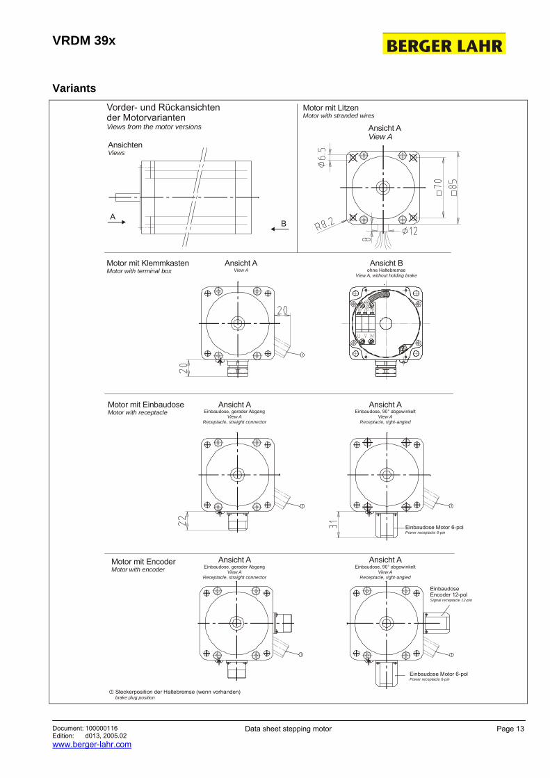
Steckerposition der Haltebremse (wenn vorhanden)brake plug position
1
Vorder- und Rückansichtender MotorvariantenViews from the motor versions
Motor mit EncoderMotor with encoder
Ansicht AView A
Motor mit LitzenMotor with stranded wires
Motor mit KlemmkastenMotor with terminal box
Motor mit EinbaudoseMotor with receptacle
AB
AnsichtenViews
Ansicht Bohne Haltebremse
View A, without holding brake
Ansicht AView A
1
Ansicht AEinbaudose, 90° abgewinkelt
View AReceptacle, right-angled
Einbaudose Motor 6-polPower receptacle 6-pin
1
Ansicht AEinbaudose, gerader Abgang
View AReceptacle, straight connector
1
1
Ansicht AEinbaudose, gerader Abgang
View AReceptacle, straight connector
1
Ansicht AEinbaudose, 90° abgewinkelt
View AReceptacle, right-angled
Einbaudose Motor 6-polPower receptacle 6-pin
EinbaudoseEncoder 12-polSignal receptacle 12-pin
VRDM 39x
Document: 100000116 Edition: d013, 2005.02 www.berger-lahr.com
Data sheet stepping motor Page 14
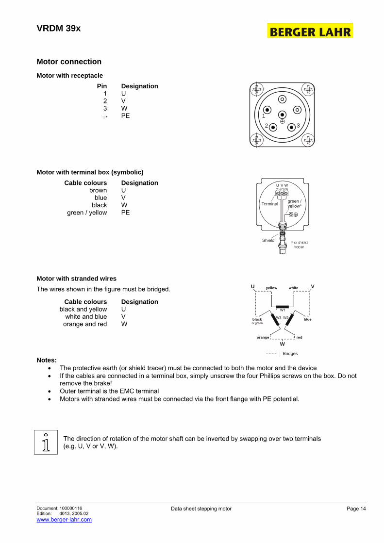
Motor connection
Motor with receptacle Pin
1 2 3
Designation U V W PE 1
2 3
Motor with terminal box (symbolic) Cable colours
brown blue
black green / yellow
Designation U V W PE
green /yellow*Terminal
U(1)
W(3)
V(2)
Shield * or shield tracer
Motor with stranded wires The wires shown in the figure must be bridged.
Cable colours black and yellow
white and blue orange and red
Designation U V W
= Bridges
W1
W2W3
U V
W
Notes:
• The protective earth (or shield tracer) must be connected to both the motor and the device • If the cables are connected in a terminal box, simply unscrew the four Phillips screws on the box. Do not
remove the brake! • Outer terminal is the EMC terminal • Motors with stranded wires must be connected via the front flange with PE potential.
The direction of rotation of the motor shaft can be inverted by swapping over two terminals (e.g. U, V or V, W).


![3-PHASE STEPPING MOTOR VRDM 39xVRDM 39x Document: 100000116 Edition: d013, 2005.02 Data sheet stepping motor Page 3 Characteristic curves VRDM 3910 VRDM 3910 / 50L H n (1/mni ) [rpm]](https://img.pdfslide.net/doc/110x75/6121c1649075995bf6467eea/3-phase-stepping-motor-vrdm-vrdm-39x-document-100000116-edition-d013-200502.jpg)