Embed Size (px)
Citation preview
© by Nozag - 2015061
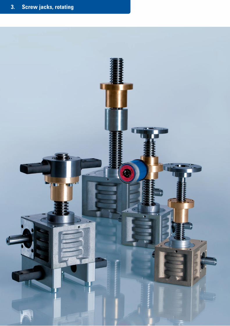
3. Screw jacks, rotating
© by Nozag - 2015 062
3. Screw jacks, rotating
The spindle has a fixed connection to the worm wheel and rotates with it. The nut therefore screws itself up and down.
The innovative Nozag screw jack kit makes it possible to create perfect drive solutions from cost-effective standard compo-nents. The kit is subject to the highest standards of functionality, quality and design. A lot can be moved with very little ex-pense and the investment, maintenance and operating costs remain within limits.
Screw jacks developed and manufactured by Nozag solve this task in a simple, inexpensive manner.
Table of Contents Page
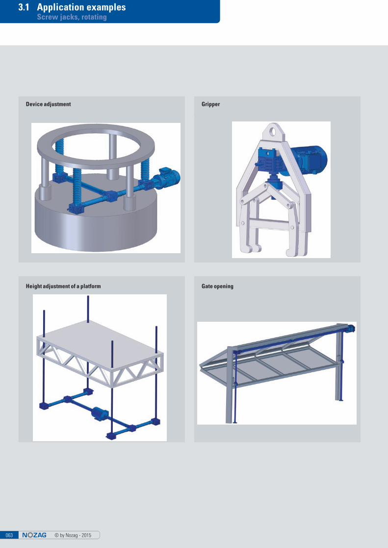
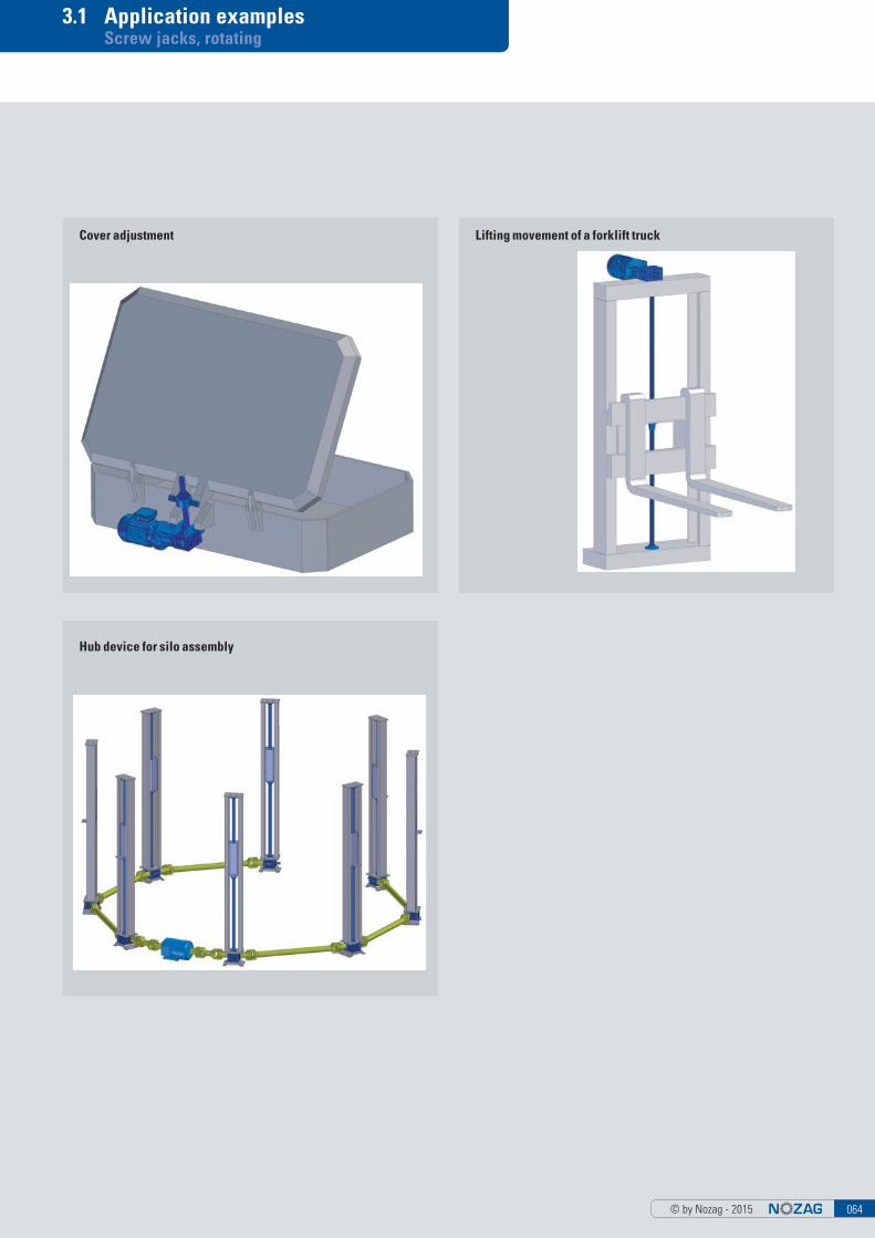
3.1 Application examples 63
3.2 Checklist 65
3.3 Sizes/system overview 67
3.4 Sizes/models 69
3.5 Attachments 79
3.6 Length determination 87
3.7 Section drawing 88
Screw Jacks «Gold» – For Extreme Environmental and Operational Conditions
The shiny casing, mounting flange and cover indicate the highest degree of corrosion resistance. In simple terms, the conventional aluminum components as well as the external parts have been replaced by components made of the aluminum bronze material CuAl10Fe5Ni5. All the spindles and shafts as well as the internal elements are manufactured from stainless steel or synthetic material (seals). ■ High corrosion stability combined with a high degree of wearing resistance
and cavitation protection through CuAl10Fe5Ni5■ Resistance against mechanical damages due to an oxide protection film
(basically Al203) that immediately forms on the material surface■ Excellent performance in applications with gases, fluids and solid materials
The CuAl10Fe5Ni5 material■ features high scaling resistance (up to 800°)■ has a lower degree of corrosion resistance to strongly acidic media with
high oxidation potential (such as nitric acid) as well as alkaline materials, because these will dissolve the oxide coating and prevent its formation.
■ has a lower tendency to selective corrosion (dealumination)
Areas of ApplicationScrew jacks of this design may be used for instance in industrial applications in the vicinity of saline water or sulfuric oxide, in slightly oxidizing and weak alkaline areas, in brackish water, in organic acids (acetate) and in reducing as well as slightly oxidizing mineral acids (diluted hydrochloric, hydrofluoric or phosphoric acid), in environments containing sulfuric acid at room tempera-ture or at elevated temperatures.
© by Nozag - 2015063
3.1 Application examples Screw jacks, rotating
2
Device adjustment Gripper
Gate openingHeight adjustment of a platform
© by Nozag - 2015 064
3.1 Application examples Screw jacks, rotating
Cover adjustment Lifting movement of a forklift truck
Hub device for silo assembly
© by Nozag - 2015065
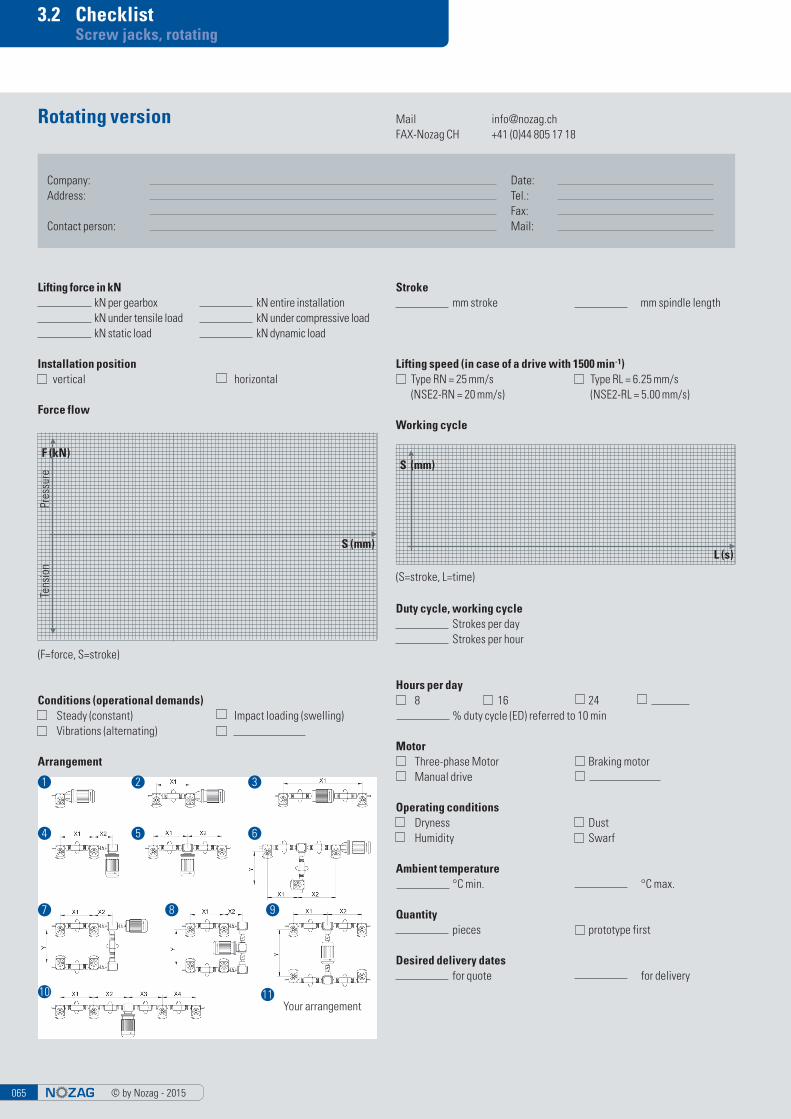
3.2 Checklist Screw jacks, rotating
Rotating version
Lifting force in kN kN per gearbox kN entire installation kN under tensile load kN under compressive load kN static load kN dynamic load
Hours per day 8 16 24 % duty cycle (ED) referred to 10 min
Operating conditions Dryness Dust Humidity Swarf
Ambient temperature °C min. °C max.
Quantity pieces prototype first
Desired delivery dates for quote for delivery
Arrangement
Working cycle
(S=stroke, L=time)
Stroke mm stroke mm spindle length
Conditions (operational demands) Steady (constant) Impact loading (swelling) Vibrations (alternating)
Lifting speed (in case of a drive with 1500 min-1) Type RN = 25 mm/s Type RL = 6.25 mm/s (NSE2-RN = 20 mm/s) (NSE2-RL = 5.00 mm/s)
Installation position vertical horizontal
Force flow
S (mm)
L (s)
(F=force, S=stroke)
F (kN)
S (mm)
Tens
ion
Pres
sure
Company: Date: Address: Tel.: Fax: Contact person: Mail:
Duty cycle, working cycle Strokes per day Strokes per hour
Motor Three-phase Motor Braking motor Manual drive
Mail [email protected] CH +41 (0)44 805 17 18
1 2 3
5 64
7 8 9
10 11Your arrangement
© by Nozag - 2015 066
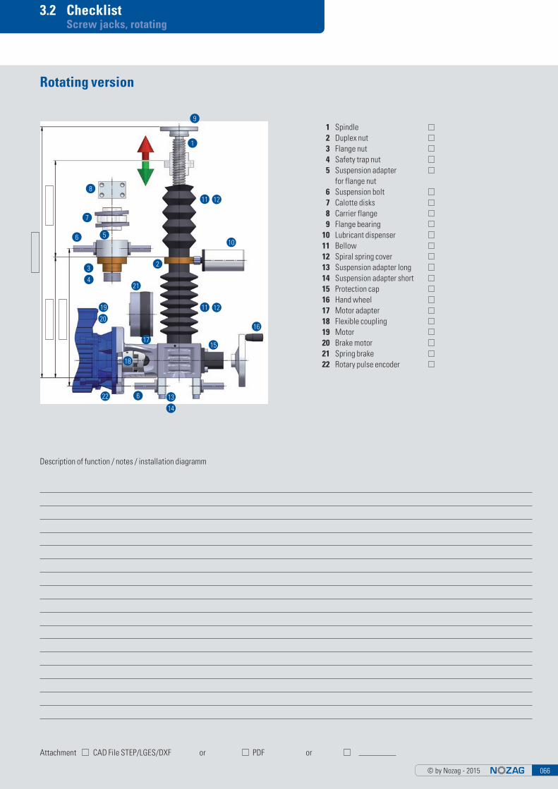
3.2 Checklist Screw jacks, rotating
Description of function / notes / installation diagramm
Attachment CAD File STEP/LGES/DXF or PDF or
Rotating version
1 Spindle 2 Duplex nut 3 Flange nut 4 Safety trap nut 5 Suspension adapter for flange nut 6 Suspension bolt 7 Calotte disks 8 Carrier flange 9 Flange bearing 10 Lubricant dispenser 11 Bellow 12 Spiral spring cover 13 Suspension adapter long 14 Suspension adapter short 15 Protection cap 16 Hand wheel 17 Motor adapter 18 Flexible coupling 19 Motor 20 Brake motor 21 Spring brake 22 Rotary pulse encoder
9
1
11
11
12
12
10
2
21
19
3
20
4
17
18
22 6 13
15
16
14
6 5
7
8
© by Nozag - 2015067
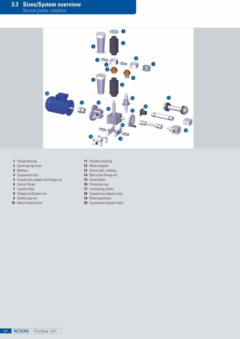
3.3 Sizes/System overview Screw jacks, rotation
1 Flange bearing 2 Spiral spring cover 3 Bellows 4 Suspension bolt 5 Suspension adapter for flange nut 6 Carrier flange 7 Calotte disks 8 Flange nut/Duplex nut 9 Safety trap nut 10 Motor/brake motor
11 Flexible coupling12 Motor adapter13 Screw jack, rotating 14 Ball screw flange nut 15 Hand wheel 16 Protection cap 17 Connecting shafts18 Suspension adapter long 19 Bevel gearboxes 20 Suspension adapter short
10
11 12
13
1
19
17
3
3
5
4 6
7
9
8
14
204
18
1516
2
2
© by Nozag - 2015 068
3.3 Sizes/System overview Screw jacks, rotating
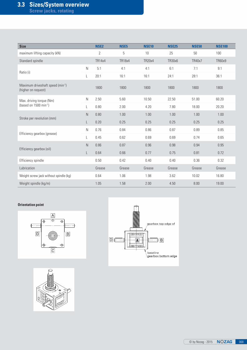
Orientation point
A
Size NSE2 NSE5 NSE10 NSE25 NSE50 NSE100
maximum lifting capacity (kN) 2 5 10 25 50 100
Standard spindle TR14x4 TR18x4 TR20x4 TR30x6 TR40x7 TR60x9
Ratio (i)N 5:1 4:1 4:1 6:1 7:1 9:1
L 20:1 16:1 16:1 24:1 28:1 36:1
Maximum driveshaft speed (min-1) (higher on request)
1800 1800 1800 1800 1800 1800
Max. driving torque (Nm)(based on 1500 min-1)
N 2.50 5.60 10.50 22.50 51.00 60.20
L 0.80 2.00 4.20 7.80 18.00 20.20
Stroke per revolution (mm)N 0.80 1.00 1.00 1.00 1.00 1.00
L 0.20 0.25 0.25 0.25 0.25 0.25
Efficiency gearbox (grease)N 0.76 0.84 0.86 0.87 0.89 0.85
L 0.45 0.62 0.69 0.69 0.74 0.65
Efficiency gearbox (oil)N 0.86 0.87 0.96 0.98 0.94 0.95
L 0.64 0.66 0.77 0.75 0.81 0.72
Efficiency spindle 0.50 0.42 0.40 0.40 0.36 0.32
Lubrication Grease Grease Grease Grease Grease Grease
Weight screw jack without spindle (kg) 0.64 1.06 1.98 3.62 10.02 16.80
Weight spindle (kg/m) 1.05 1.58 2.00 4.50 8.00 19.00
C
A
B
D
© by Nozag - 2015069
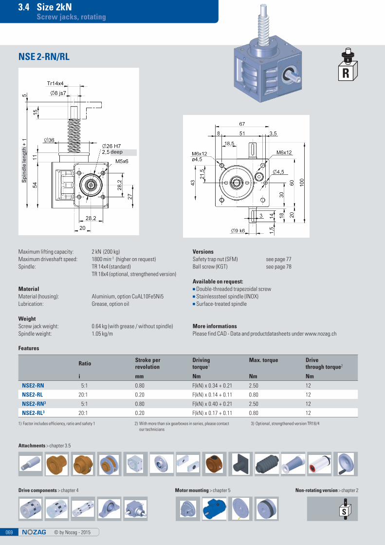
3.4 Size 2kN Screw jacks, rotating
Maximum lifting capacity: 2 kN (200 kg)Maximum driveshaft speed: 1800 min-1 (higher on request)Spindle: TR 14x4 (standard) TR 18x4 (optional, strengthened version)
MaterialMaterial (housing): Aluminium, option CuAL10Fe5Ni5Lubrication: Grease, option oil
WeightScrew jack weight: 0.64 kg (with grease / without spindle)Spindle weight: 1.05 kg/m
NSE 2-RN/RL
VersionsSafety trap nut (SFM) see page 77Ball screw (KGT) see page 78
Available on request:■ Double-threaded trapezoidal screw■ Stainlesssteel spindle (INOX)■ Surface-treated spindle
More informationsPlease find CAD - Data and productdatasheets under www.nozag.ch
Non-rotating version > chapter 2
Features
Ratio Stroke per revolution
Driving torque1
Max. torque Drive through torque2
i mm Nm Nm Nm
NSE2-RN 5:1 0.80 F(kN) x 0.34 + 0.21 2.50 12
NSE2-RL 20:1 0.20 F(kN) x 0.14 + 0.11 0.80 12
NSE2-RN3 5:1 0.80 F(kN) x 0.40 + 0.21 2.50 12
NSE2-RL3 20:1 0.20 F(kN) x 0.17 + 0.11 0.80 12
1) Factor includes efficiency, ratio and safety 1 2) With more than six gearboxes in series, please contact our technicians
3) Optional, strengthened version TR18/4
Attachments > chapter 3.5
Drive components > chapter 4 Motor mounting > chapter 5
Sp
ind
le le
ng
th deep
© by Nozag - 2015 070
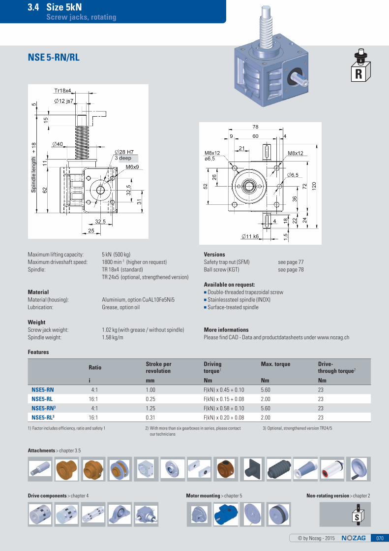
3.4 Size 5kN Screw jacks, rotating
Maximum lifting capacity: 5 kN (500 kg)Maximum driveshaft speed: 1800 min-1 (higher on request)Spindle: TR 18x4 (standard) TR 24x5 (optional, strengthened version)
MaterialMaterial (housing): Aluminium, option CuAL10Fe5Ni5Lubrication: Grease, option oil
WeightScrew jack weight: 1.02 kg (with grease / without spindle)Spindle weight: 1.58 kg/m
NSE 5-RN/RL
VersionsSafety trap nut (SFM) see page 77Ball screw (KGT) see page 78
Available on request:■ Double-threaded trapezoidal screw■ Stainlesssteel spindle (INOX)■ Surface-treated spindle
More informationsPlease find CAD - Data and productdatasheets under www.nozag.ch
Non-rotating version > chapter 2
Features
Ratio Stroke per revolution
Driving torque1
Max. torque Drive- through torque2
i mm Nm Nm Nm
NSE5-RN 4:1 1.00 F(kN) x 0.45 + 0.10 5.60 23
NSE5-RL 16:1 0.25 F(kN) x 0.15 + 0.08 2.00 23
NSE5-RN3 4:1 1.25 F(kN) x 0.58 + 0.10 5.60 23
NSE5-RL3 16:1 0.31 F(kN) x 0.20 + 0.08 2.00 23
1) Factor includes efficiency, ratio and safety 1 2) With more than six gearboxes in series, please contact our technicians
3) Optional, strengthened version TR24/5
Attachments > chapter 3.5
Drive components > chapter 4 Motor mounting > chapter 5
Sp
ind
le le
ng
th deep
© by Nozag - 2015071
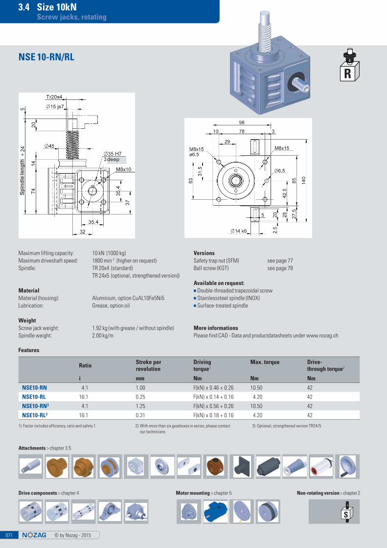
3.4 Size 10kN Screw jacks, rotating
Maximum lifting capacity: 10 kN (1000 kg)Maximum driveshaft speed: 1800 min-1 (higher on request)Spindle: TR 20x4 (standard) TR 24x5 (optional, strengthened version))
MaterialMaterial (housing): Aluminium, option CuAL10Fe5Ni5Lubrication: Grease, option oil
WeightScrew jack weight: 1.92 kg (with grease / without spindle)Spindle weight: 2.00 kg/m
NSE 10-RN/RL
VersionsSafety trap nut (SFM) see page 77Ball screw (KGT) see page 78
Available on request:■ Double-threaded trapezoidal screw■ Stainlesssteel spindle (INOX)■ Surface-treated spindle
More informationsPlease find CAD - Data and productdatasheets under www.nozag.ch
Non-rotating version > chapter 2
Features
Ratio Stroke per revolution
Driving torque1
Max. torque Drive- through torque2
i mm Nm Nm Nm
NSE10-RN 4:1 1.00 F(kN) x 0.46 + 0.26 10.50 42
NSE10-RL 16:1 0.25 F(kN) x 0.14 + 0.16 4.20 42
NSE10-RN3 4:1 1.25 F(kN) x 0.56 + 0.26 10.50 42
NSE10-RL3 16:1 0.31 F(kN) x 0.18 + 0.16 4.20 42
1) Factor includes efficiency, ratio and safety 1 2) With more than six gearboxes in series, please contact our technicians
3) Optional, strengthened version TR24/5
Attachments > chapter 3.5
Drive components > chapter 4 Motor mounting > chapter 5
Sp
ind
le le
ng
th
deep
© by Nozag - 2015 072
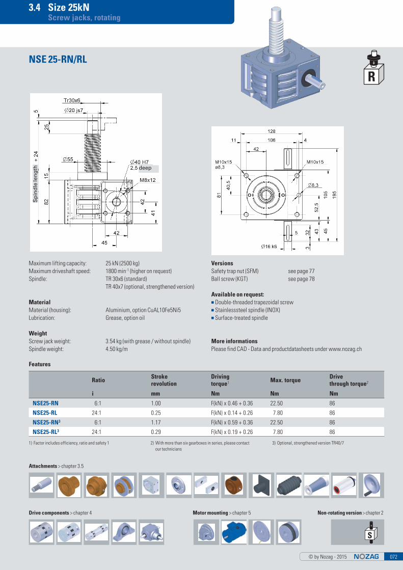
3.4 Size 25kN Screw jacks, rotating
Maximum lifting capacity: 25 kN (2500 kg)Maximum driveshaft speed: 1800 min-1 (higher on request)Spindle: TR 30x6 (standard) TR 40x7 (optional, strengthened version)
MaterialMaterial (housing): Aluminium, option CuAL10Fe5Ni5Lubrication: Grease, option oil
WeightScrew jack weight: 3.54 kg (with grease / without spindle)Spindle weight: 4.50 kg/m
NSE 25-RN/RL
VersionsSafety trap nut (SFM) see page 77Ball screw (KGT) see page 78
Available on request:■ Double-threaded trapezoidal screw■ Stainlesssteel spindle (INOX)■ Surface-treated spindle
More informationsPlease find CAD - Data and productdatasheets under www.nozag.ch
Non-rotating version > chapter 2
Features
Ratio Stroke revolution
Driving torque1 Max. torque Drive
through torque2
i mm Nm Nm Nm
NSE25-RN 6:1 1.00 F(kN) x 0.46 + 0.36 22.50 86
NSE25-RL 24:1 0.25 F(kN) x 0.14 + 0.26 7.80 86
NSE25-RN3 6:1 1.17 F(kN) x 0.59 + 0.36 22.50 86
NSE25-RL3 24:1 0.29 F(kN) x 0.19 + 0.26 7.80 86
1) Factor includes efficiency, ratio and safety 1 2) With more than six gearboxes in series, please contact our technicians
3) Optional, strengthened version TR40/7
Attachments > chapter 3.5
Drive components > chapter 4 Motor mounting > chapter 5
Sp
ind
le le
ng
th deep
© by Nozag - 2015073
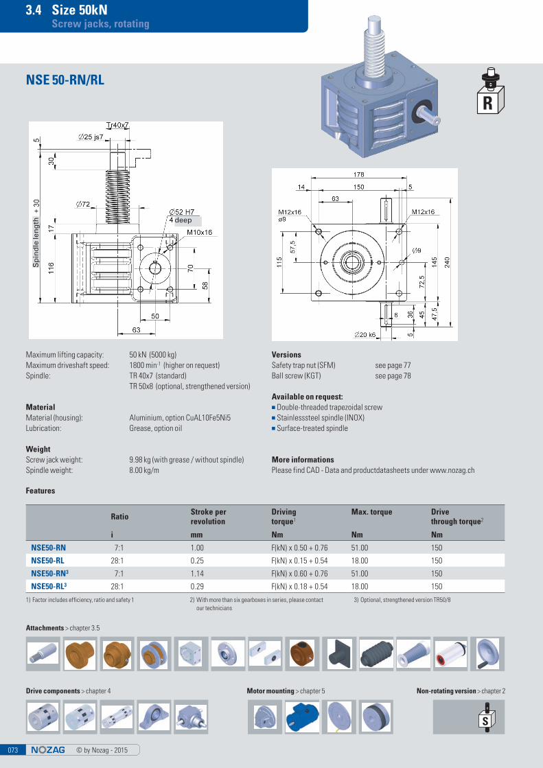
3.4 Size 50kN Screw jacks, rotating
Maximum lifting capacity: 50 kN (5000 kg)Maximum driveshaft speed: 1800 min-1 (higher on request)Spindle: TR 40x7 (standard) TR 50x8 (optional, strengthened version)
MaterialMaterial (housing): Aluminium, option CuAL10Fe5Ni5Lubrication: Grease, option oil
WeightScrew jack weight: 9.98 kg (with grease / without spindle)Spindle weight: 8.00 kg/m
NSE 50-RN/RL
VersionsSafety trap nut (SFM) see page 77Ball screw (KGT) see page 78
Available on request:■ Double-threaded trapezoidal screw■ Stainlesssteel spindle (INOX)■ Surface-treated spindle
More informationsPlease find CAD - Data and productdatasheets under www.nozag.ch
Non-rotating version > chapter 2
Features
Ratio Stroke per revolution
Driving torque1
Max. torque Drive through torque2
i mm Nm Nm Nm
NSE50-RN 7:1 1.00 F(kN) x 0.50 + 0.76 51.00 150
NSE50-RL 28:1 0.25 F(kN) x 0.15 + 0.54 18.00 150
NSE50-RN3 7:1 1.14 F(kN) x 0.60 + 0.76 51.00 150
NSE50-RL3 28:1 0.29 F(kN) x 0.18 + 0.54 18.00 150
1) Factor includes efficiency, ratio and safety 1 2) With more than six gearboxes in series, please contact our technicians
3) Optional, strengthened version TR50/8
Attachments > chapter 3.5
Drive components > chapter 4 Motor mounting > chapter 5
Sp
ind
le le
ng
th deep
© by Nozag - 2015 074
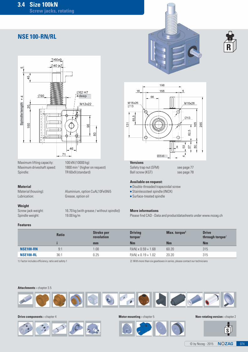
3.4 Size 100kN Screw jacks, rotating
Maximum lifting capacity: 100 kN (10000 kg)Maximum driveshaft speed: 1800 min-1 (higher on request)Spindle: TR 60x9 (standard)
MaterialMaterial (housing): Aluminium, option CuAL10Fe5Ni5Lubrication: Grease, option oil
WeightScrew jack weight: 16.70 kg (with grease / without spindle))Spindle weight: 19.00 kg/m
NSE 100-RN/RL
VersionsSafety trap nut (SFM) see page 77Ball screw (KGT) see page 78
Available on request:■ Double-threaded trapezoidal screw■ Stainlesssteel spindle (INOX)■ Surface-treated spindle
More informationsPlease find CAD - Data and productdatasheets under www.nozag.ch
Non-rotating version > chapter 2
Features
Ratio Stroke per revolution
Driving torque1
Max. torque1 Drive through torque2
i mm Nm Nm Nm
NSE100-RN 9:1 1.00 F(kN) x 0.59 + 1.68 60.20 315
NSE100-RL 36:1 0.25 F(kN) x 0.19 + 1.02 20.20 315
1) Factor includes efficiency, ratio and safety 1 2) With more than six gearboxes in series, please contact our technicians
Ø25 k6
Attachments > chapter 3.5
Drive components > chapter 4 Motor mounting > chapter 5
Sp
ind
le le
ng
th
deep
© by Nozag - 2015075
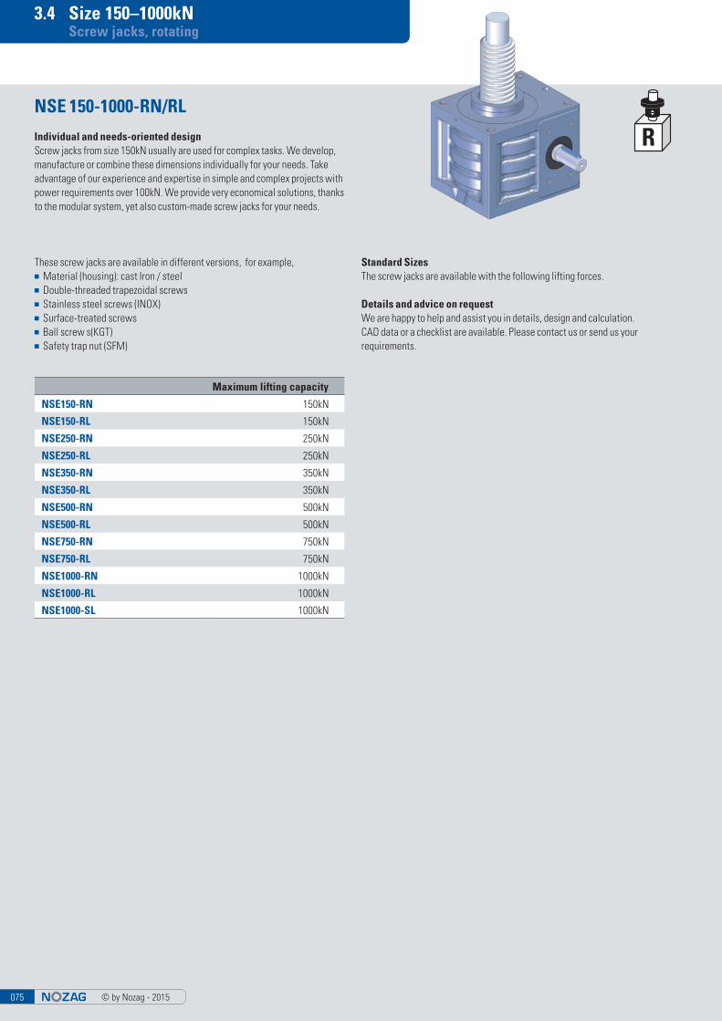
3.4 Size 150–1000kN Screw jacks, rotating
NSE 150-1000-RN/RL
Maximum lifting capacity
NSE150-RN 150kN
NSE150-RL 150kN
NSE250-RN 250kN
NSE250-RL 250kN
NSE350-RN 350kN
NSE350-RL 350kN
NSE500-RN 500kN
NSE500-RL 500kN
NSE750-RN 750kN
NSE750-RL 750kN
NSE1000-RN 1000kN
NSE1000-RL 1000kN
NSE1000-SL 1000kN
Individual and needs-oriented designScrew jacks from size 150kN usually are used for complex tasks. We develop, manufacture or combine these dimensions individually for your needs. Take advantage of our experience and expertise in simple and complex projects with power requirements over 100kN. We provide very economical solutions, thanks to the modular system, yet also custom-made screw jacks for your needs.
These screw jacks are available in different versions, for example,■ Material (housing): cast Iron / steel■ Double-threaded trapezoidal screws■ Stainless steel screws (INOX)■ Surface-treated screws■ Ball screw s(KGT)■ Safety trap nut (SFM)
Standard SizesThe screw jacks are available with the following lifting forces.
Details and advice on requestWe are happy to help and assist you in details, design and calculation. CAD data or a checklist are available. Please contact us or send us your requirements.
© by Nozag - 2015 076
3.4 Size 150–1000kN Screw jacks, rotating
© by Nozag - 2015077
3.4 Safety trap nut (SFM) Screw jacks, rotating
FunctionThe safety trap nut acts in only one direction, it runs alongside without load. In case of fracture of the travelling nut, the load bears on the trap nut.
The wear can be checked through the distance «S». As soon as the dimension «S» is reduced by more than 20% of the thread pitch (= 40% of the tooth thick-ness), the travelling nut must be replaced.
Load directionPlease exactly check the load direction (tension or compression). A drawing with a depiction of the functions is necessary to ensure the safety function.
Electronic wear monitoring is available upon request.
H1 H2 H3 H4 S
NSE2 54 11 4 49.0 2.0
NSE5 62 11 4 49.0 2.0
NSE10 74 14 4 60.0 2.0
NSE25 82 15 6 77.0 3.0
NSE50 116 17 7 97.5 3.5
NSE100 160 20 9 134.5 4.5
© by Nozag - 2015 078
3.4 Ball screw (KGT) Screw jacks, rotating
Pitch accuracy0,05 mm/300 mm
Self-lockingNone! Therefore, braking motor or spring-loaded brake FDB necessary
FoulingNuts are always fitted with scrapers. In case of serious fouling and fine dust/swarf, we recommend installing bellows or a spiral spring cover.
LubricationAdequate lubrication is an important factor to insure the life of the system, reducing friction and ensuring smooth running. For KGT we use the same lubricants as for ball bearings.
LockingThe spindles or nuts must not be unscrewed or disengaged under any circum-stances.
System starting and brakingEspecially with high pitches and large gearboxes we recommend the use of a frequency inverter or a soft start for acceleration and deceleration. This provi-des protection for the whole system. Subject to a suitable control system being used the safety distance may be reduced. Please contact the technical department for more information.
Switching-on timeOwing to the lower heat generation with ball screws, you can multiply the swit-ching-on times (ED in % per 10’) by a factor of 2. Please contact us regarding ap-plications with a switching-on time greater than 40 % (4 min per 10 min).
* Stroke per revolution (mm)
Load rating [kN]
KGT RN* RL* Nut shapeHole
patternB D2 D3 D4 D5 G H1 H2
H3 (min.)
L1 L2 L3 L4Axial play
(max)dy-
namicstatic
NSE5 16x5 1.25 0.31 E 1 40 28 38 48 5.5 M6 62 11 10 42 10 10 – 0.08 9.3 13.1
16x10 2.50 0.63 E 1 40 28 38 48 5.5 M6 62 11 20 55 10 10 – 0.08 15.4 26.5
NSE10 25x5 1.25 0.31 E 1 48 40 51 62 6.6 M6 74 14 10 42 10 10 – 0.08 12.3 22.5
25x10 2.50 0.63 E 1 48 40 51 62 6.6 M6 74 14 20 55 10 16 – 0.08 13.2 25.3
25x25 6.25 1.56 S 1 48 40 51 62 6.6 M6 74 14 50 35 10 9 8 0.08 16.7 32.2
25x50 12.50 3.13 S 1 48 40 51 62 6.6 M6 74 14 100 58 10 10 10 0.08 15.4 31.7
NSE25 32x5 0.83 0.21 E 1 62 50 65 80 9.0 M6 82 15 10 55 12 10 – 0.08 21.5 49.3
32x10 1.67 0.42 E 1 62 53 65 80 9.0 M6 82 15 20 69 12 16 – 0.08 33.4 54.5
32x20 3.33 0.83 E 1 62 53 65 80 9.0 M8x1 82 15 40 80 12 16 – 0.08 29.7 59.8
32x40 6.67 1.67 S 6x60° (round) 53 68 80 7.0 M6 82 15 80 45 16 14 7.5 0.08 14.9 32.4
NSE50 40x5 0.71 0.18 E 2 70 63 78 93 9.0 M6 116 17 10 57 14 10 – 0.08 23.8 63.1
40x10 1.43 0.36 E 2 70 63 78 93 9.0 M8x1 116 17 20 71 14 16 – 0.08 38.0 69.1
40x20 2.86 0.71 E 2 70 63 78 93 9.0 M8x1 116 17 40 80 14 16 – 0.08 33.3 76.1
40x40 5.71 1.43 S 2 (round) 63 78 93 9.0 M8x1 116 17 80 85 14 16 7.5 0.08 35.0 101.9
NSE100 50x10 1.25 0.31 E 2 85 75 93 110 11.0 M8x1 160 20 20 95 16 16 – 0.08 68.7 155.8
50x20 2.50 0.63 E 2 95 85 103 125 11.0 M8x1 160 20 40 95 18 22 – 0.08 60.0 136.3
© by Nozag - 2015079
3.5 Attachments Screw jacks, rotating
Flange nut FM
TR D L
NSE2-TRZ TR14x4 8 15
NSE5-TRZ TR18x4 12 15
NSE10-TRZ TR20x4 15 20
NSE25-TRZ TR30x6 20 25
NSE50-TRZ TR40x7 25 30
NSE100-TRZ TR60x9 40 45
Spindle end, rotating spindle TRZ
TR D1 D2 D3 D4 L1 L2 L3
NSE2-FM TR14x4 38 6 28 48 35 12 8NSE5-FM TR18x4 38 6 28 48 35 12 8NSE10-FM TR20x4 45 7 32 55 44 12 8NSE25-FM TR30x6 50 7 38 62 46 14 8NSE50-FM TR40x7 78 9 63 95 66 16 12
NSE100-FM TR60x9 110 13 88 130 90 20 16
TR
NSE2-TR TR14x4
NSE5-TR TR18x4
NSE10-TR TR20x4
NSE25-TR TR30x6
NSE50-TR TR40x7
NSE100-TR TR60x9
Spindle end, rotating spindle TR
© by Nozag - 2015 080
3.5 Attachments Screw jacks, rotating
Calotte disks KS fitting duplex nut DMN
Safety trap nut SFM
D5 L5 L6
NSE2-R-SFM 25 12 2.0
NSE5-R-SFM 25 12 2.0
NSE10-R-SFM 31 14 2.0
NSE25-R-SFM 40 20 3.0
NSE50-R-SFM 58 28 3.5
NSE100-R-SFM 74 40 4.5
Duplex nut DMN
Remaining dimensions are the same as duplex nut
TR D1 D2 D3 D4 L1 L2 L3 L4
NSE2-DMN TR14x4 38 6 28 48 35 11.5 12 8NSE5-DMN TR18x4 38 6 28 48 35 11.5 12 8NSE10-DMN TR20x4 45 7 32 55 44 16.0 12 8NSE25-DMN TR30x6 58 7 45 70 54 19.0 16 10
NSE50-DMN TR40x7 78 9 63 95 66 25.0 16 12
NSE100-DMN TR60x9 110 13 88 130 90 35.0 20 16
TR D1 D2 D3 D4 L1 L2
NSE2-KS TR14x4 38 6 50 28 27 12
NSE5-KS TR18x4 38 6 50 28 27 12
NSE10-KS TR20x4 45 7 60 32 32 12
NSE25-KS TR30x6 58 7 80 45 36 16
NSE50-KS TR40x7 78 9 100 63 42 16
NSE100-KS TR60x9 110 13 140 88 52 20
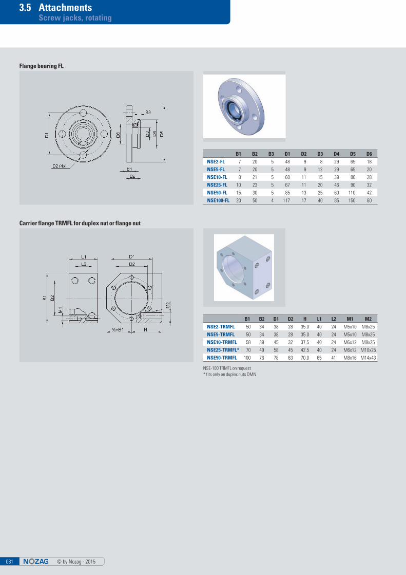
© by Nozag - 2015081
3.5 Attachments Screw jacks, rotating
Carrier flange TRMFL for duplex nut or flange nut
Flange bearing FL
NSE-100 TRMFL on request* fits only on duplex nuts DMN
B1 B2 B3 D1 D2 D3 D4 D5 D6
NSE2-FL 7 20 5 48 9 8 29 65 18
NSE5-FL 7 20 5 48 9 12 29 65 20
NSE10-FL 8 21 5 60 11 15 39 80 28
NSE25-FL 10 23 5 67 11 20 46 90 32
NSE50-FL 15 30 5 85 13 25 60 110 42
NSE100-FL 20 50 4 117 17 40 85 150 60
B1 B2 D1 D2 H L1 L2 M1 M2
NSE2-TRMFL 50 34 38 28 35.0 40 24 M5x10 M8x25
NSE5-TRMFL 50 34 38 28 35.0 40 24 M5x10 M8x25
NSE10-TRMFL 58 39 45 32 37.5 40 24 M6x12 M8x25
NSE25-TRMFL* 70 49 58 45 42.5 40 24 M6x12 M10x25
NSE50-TRMFL 100 76 78 63 70.0 65 41 M8x16 M14x43
© by Nozag - 2015 082
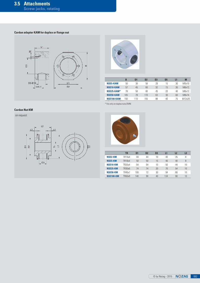
3.5 Attachments Screw jacks, rotating
NSE2-KAM on request
Cardan adapter KAM for duplex or flange nut
TR D1 D2 D3 L1 L2 L3
NSE2-KM TR14x4 44 44 10 40 35 8
NSE5-KM TR18x4 50 50 15 46 40 8
NSE10-KM TR20x4 54 54 15 50 44 10
NSE25-KM TR30x6 74 74 20 70 54 10
NSE50-KM TR40x7 100 72 30 94 66 10
NSE100-KM TR60x9 140 90 40 134 90 10
B D1 D2 D3 D5 L1 M
NSE5-KAM 50 38 58 28 15 30 M5x10
NSE10-KAM 57 45 60 32 15 30 M6x12
NSE25-KAM* 78 58 80 45 20 40 M6x12
NSE50-KAM 105 78 110 63 30 60 M8x14
NSE100-KAM 150 110 155 88 40 75 M12x20
* fits only on duplex nuts DMN
Cardan Nut KM
on request
© by Nozag - 2015083
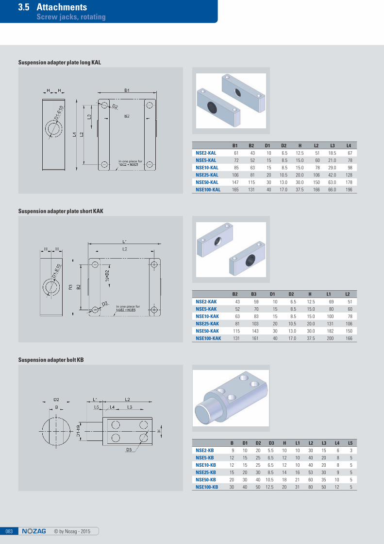
3.5 Attachments Screw jacks, rotating
Suspension adapter plate long KAL
Suspension adapter plate short KAK
Suspension adapter bolt KB
B2 B3 D1 D2 H L1 L2
NSE2-KAK 43 59 10 6.5 12.5 69 51
NSE5-KAK 52 70 15 8.5 15.0 80 60
NSE10-KAK 63 83 15 8.5 15.0 100 78
NSE25-KAK 81 103 20 10.5 20.0 131 106
NSE50-KAK 115 143 30 13.0 30.0 182 150
NSE100-KAK 131 161 40 17.0 37.5 200 166
B D1 D2 D3 H L1 L2 L3 L4 L5
NSE2-KB 9 10 20 5.5 10 10 30 15 6 3
NSE5-KB 12 15 25 6.5 12 10 40 20 8 5
NSE10-KB 12 15 25 6.5 12 10 40 20 8 5
NSE25-KB 15 20 30 8.5 14 16 53 30 9 5
NSE50-KB 20 30 40 10.5 18 21 60 35 10 5
NSE100-KB 30 40 50 12.5 20 31 80 50 12 5
B1 B2 D1 D2 H L2 L3 L4
NSE2-KAL 61 43 10 6.5 12.5 51 18.5 67
NSE5-KAL 72 52 15 8.5 15.0 60 21.0 78
NSE10-KAL 85 63 15 8.5 15.0 78 29.0 98
NSE25-KAL 106 81 20 10.5 20.0 106 42.0 128
NSE50-KAL 147 115 30 13.0 30.0 150 63.0 178
NSE100-KAL 165 131 40 17.0 37.5 166 66.0 196
in one piece for
in one piece for
© by Nozag - 2015 084
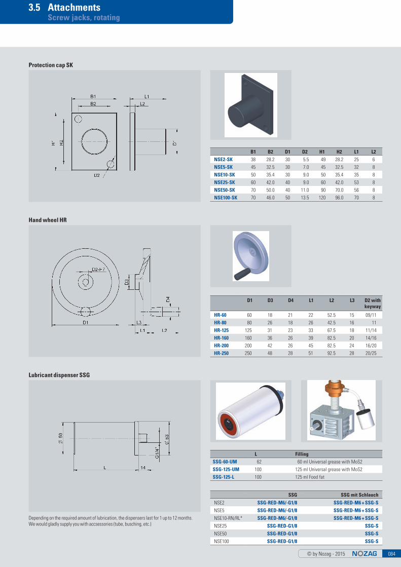
3.5 Attachments Screw jacks, rotating
Protection cap SK
Hand wheel HR
D1 D3 D4 L1 L2 L3 D2 with keyway
HR-60 60 18 21 22 52.5 15 09/11
HR-80 80 26 18 26 42.5 16 11
HR-125 125 31 23 33 67.5 18 11/14
HR-160 160 36 26 39 82.5 20 14/16
HR-200 200 42 26 45 82.5 24 16/20
HR-250 250 48 28 51 92.5 28 20/25
B1 B2 D1 D2 H1 H2 L1 L2
NSE2-SK 38 28.2 30 5.5 49 28.2 25 6
NSE5-SK 45 32.5 30 7.0 45 32.5 32 8
NSE10-SK 50 35.4 30 9.0 50 35.4 35 8
NSE25-SK 60 42.0 40 9.0 60 42.0 53 8
NSE50-SK 70 50.0 40 11.0 90 70.0 56 8
NSE100-SK 70 46.0 50 13.5 120 96.0 70 8
Lubricant dispenser SSG
L Filling
SSG-60-UM 62 60 ml Universal grease with MoS2
SSG-125-UM 100 125 ml Universal grease with MoS2
SSG-125-L 100 125 ml Food fat
Depending on the required amount of lubrication, the dispensers last for 1 up to 12 months.We would gladly supply you with accsessories (tube, busching, etc.)
SSG SSG mit Schlauch
NSE2 SSG-RED-M6/-G1/8 SSG-RED-M6 + SSG-S
NSE5 SSG-RED-M6/-G1/8 SSG-RED-M6 + SSG-S
NSE10-RN/RL* SSG-RED-M6/-G1/8 SSG-RED-M6 + SSG-S
NSE25 SSG-RED-G1/8 SSG-S
NSE50 SSG-RED-G1/8 SSG-S
NSE100 SSG-RED-G1/8 SSG-S
© by Nozag - 2015085
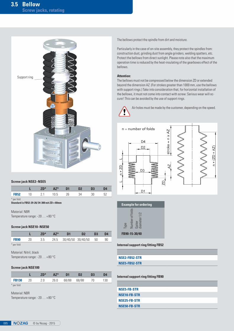
3.5 Bellow Screw jacks, rotating
The bellows protect the spindle from dirt and moisture.
Particularly in the case of on-site assembly, they protect the spindles from: construction dust, grinding dust from angle grinders, welding spatters, etc. Protect the bellows from direct sunlight. Please note also that the maximum operation time is reduced by the heat-insulating of the gearboxes effect of the bellows.
Attention:The bellows must not be compressed below the dimension ZD or extended beyond the dimension AZ. (For strokes greater than 1000 mm, use the bellows with support rings.) Take into consideration that, for horizontal installation of the bellows, it must not come into contact with screw: Serious wear will oc-cure! This can be avoided by the use of support rings.
Example for ordering
Type
Num
ber o
f fol
dsGa
iter
diam
eter
1/2
FB90-15-30/40
L ZD* AZ* D1 D2 D3 D4
FB52 10 2.1 10.5 26 34 30 52
Screw jack NSE2–NSE5
Material: NBRTemperature range: - 20 … + 80 °C
L ZD* AZ* D1 D2 D3 D4
FB130 20 2.0 26.0 68/88 68/88 70 130
Screw jack NSE100
Material: NBRTemperature range: - 20 … + 80 °C
L ZD* AZ* D1 D2 D3 D4
FB90 20 3.5 24.5 30/40/50 30/40/50 50 90
Screw jack NSE10–NSE50
Material: Nitril, blackTemperature range: - 20 … + 80 °C
* per foldStandard is FB52-29-26/ 34-300 mit ZD = 60mm
* per fold
* per fold
Air holes must be made by the customer, depending on the speed.
Internal support ring fitting FB90
NSE5-FB-STR
NSE10-FB-STR
NSE25-FB-STR
NSE50-FB-STR
Internal support ring fitting FB52
NSE2-FB52-STR
NSE5-FB52-STR
Support ring
© by Nozag - 2015 086
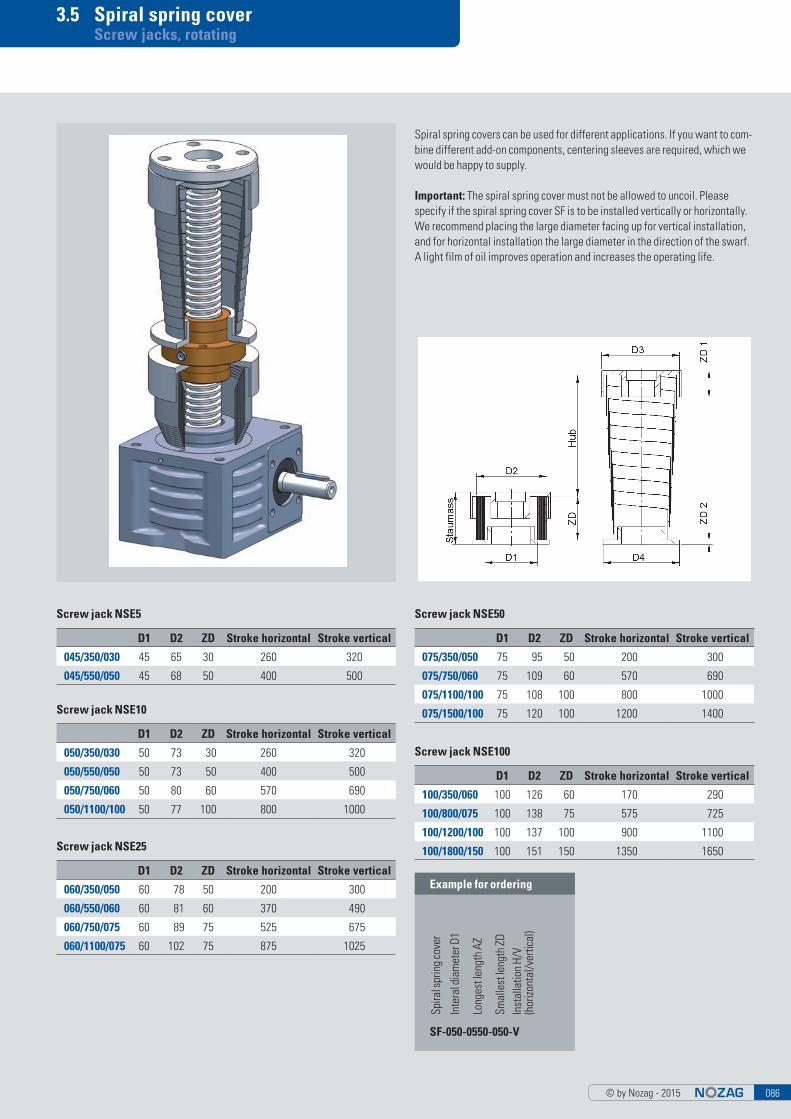
3.5 Spiral spring cover Screw jacks, rotating
Spiral spring covers can be used for different applications. If you want to com-bine different add-on components, centering sleeves are required, which we would be happy to supply.
Important: The spiral spring cover must not be allowed to uncoil. Please specify if the spiral spring cover SF is to be installed vertically or horizontally. We recommend placing the large diameter facing up for vertical installation, and for horizontal installation the large diameter in the direction of the swarf. A light film of oil improves operation and increases the operating life.
Example for ordering
Inte
ral d
iam
eter
D1
Spira
l spr
ing
cove
r
Long
est l
engt
h AZ
Smal
lest
leng
th Z
DIn
stal
latio
n H/
V (h
orizo
ntal
/ver
tical
)
SF-050-0550-050-V
D1 D2 ZD Stroke horizontal Stroke vertical
045/350/030 45 65 30 260 320
045/550/050 45 68 50 400 500
D1 D2 ZD Stroke horizontal Stroke vertical
050/350/030 50 73 30 260 320
050/550/050 50 73 50 400 500
050/750/060 50 80 60 570 690
050/1100/100 50 77 100 800 1000
D1 D2 ZD Stroke horizontal Stroke vertical
075/350/050 75 95 50 200 300
075/750/060 75 109 60 570 690
075/1100/100 75 108 100 800 1000
075/1500/100 75 120 100 1200 1400
D1 D2 ZD Stroke horizontal Stroke vertical
060/350/050 60 78 50 200 300
060/550/060 60 81 60 370 490
060/750/075 60 89 75 525 675
060/1100/075 60 102 75 875 1025
D1 D2 ZD Stroke horizontal Stroke vertical
100/350/060 100 126 60 170 290
100/800/075 100 138 75 575 725
100/1200/100 100 137 100 900 1100
100/1800/150 100 151 150 1350 1650
Screw jack NSE5
Screw jack NSE10
Screw jack NSE50
Screw jack NSE25
Screw jack NSE100
© by Nozag - 2015087
3.6 Length determination Screw jacks, rotating
By means of the following table, you can determine the required spindle lengths. So that you can quickly calculate the installation dimensions of your screw jack. These allowances are the minimum required. For special installation situations, please make a drawing or contact us.
ExplanationSpindle length = stroke + basic length + attachments
Calculation example
NSE25-RL with 270 mm stroke with pin for flange bearing, Duplex nut and bellow
Spindle length270 + 110 + 54 + 42 = 476 mm spindle length
Smallest length bellow270/24.5 = 11.02 > 12 x 3.5 = 42
NSE2 NSE5 NSE10 NSE25 NSE50 NSE100
TR-basic length* 72 63 72 85 117 194
KGT-basic length** 75 16x05 84 25x05 93 32x05 123 40x05 216 50x10
95 16x10 104 25x10 113 32x10 143 40x10 256 50x20
164 25x25 153 32x20 183 40x20
264 25x50 233 32x40 263 40x40
Basic length without safety 64 55 64 73 103 176
Pin length 15 15 20 25 30.0 45.0
Flange nut 35 35 44 46 66.0 90.0
Flange nut with SFM 49 49 60 69 97.5 134.5
Duplex nut 35 35 44 54 66.0 90.0
Duplex nut with SFM 49 49 60 77 97.5 134.5
KGT-nut L1 see page 78 42 16x05 42 25x05 55 32x05 57 95 50x10
55 16x10 55 25x10 69 32x10 71 40x10 95 50x10
35 25x25 80 32x20 80 40x20
58 25x50 45 32x40 85 40x40
Smallest length bellowStroke/10.5 = ........ x 2.1
round number
Stroke/10.5 = ........ x 2.1 round number
Stroke/24.5 = ........ x 3.5 round number
Stroke/24.5 = ........ x 3.5 round number
Stroke/24.5 = ........ x 3.5 round number
Stroke/26.0 = ........ x 2.0 round number
* Contains 2 x the safety distance (spindle pitch)** Contains 4 x the safety distance (spindle pitch) Subject to dimension changes
■ Spiral spring cover SF: As the extension in case of a spiral spring cover is different depending on the attachment, this option has to be determined graphically. We would be happy to generate this drawing for you.
CAD data can be found at www.nozag.ch
© by Nozag - 2015 088
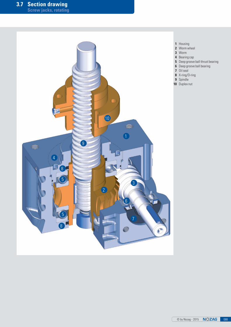
3.7 Section drawing Screw jacks, rotating
1 Housing 2 Worm wheel 3 Worm 4 Bearing cap 5 Deep groove ball thrust bearing 6 Deep groove ball bearing 7 Oil seal 8 X-ring/O-ring 9 Spindle 10 Duplex nut
1
10
9
4
8
5
5
8
2
3
6
7