Embed Size (px)
Citation preview
Rift Basin Architecture & Evolution http://www.ldeo.columbia.edu/~polsen/nbcp/breakup...
1 of 13 7/19/06 3:05 PM
N.B., FOR BEST RESULTS, PRINT AT 85%Previous Next
3.3. Tectonics of Rifting and Drifting: Pangea Breakup
3.3.1. Rift Basin Architecture and Evolution
Roy W. Schlische & Martha Oliver Withjack Department of Geological Sciences, Rutgers University, Piscataway, NJ 08854-8066 U.S.A.
Rift basins have been increasingly the focus of research in tectonics,structural geology, and basin analysis. The reasons for this interestinclude: (1) Rift basins are found on all passive (Atlantic-type)continental margins and provide a record of the early stages of (super)continental breakup. (2) The architecture of these basins and thebasin fill are strongly influenced by the displacement geometry on thebounding normal fault systems (e.g., Gibson et al., 1989). Thus, aspectsof the evolution of these fault systems, including their nucleation,propagation and linkage, can be extracted from the sedimentary record.(3) Many modern and ancient extensional basins contain lacustrinedeposits (e.g., Katz, 1990) that are sensitive recorders of climate.Milankovitch cycles (e.g., Olsen and Kent, 1999) recorded in these strataprovide a quantitative test of the predictions of basin-filling models(e.g., Schlische and Olsen, 1990) that can, in turn, be used to inferaspects of crustal rheology during rifting (e.g., Contreras et al., 1997).(4) Many of the major petroleum provinces of the world are associatedwith rift basins (e.g., the North Sea basins, the Jeanne d'Arc basin, theBrazilian rift basins).
This section provides a brief overview of the rift basins related toPangean breakup, especially those along the central Atlantic margin(e.g., Olsen, 1997). In particular, we examine (1) the structuralarchitecture of rift basins; (2) the interplay of tectonics, sediment supply, and climate in controlling the large-scale stratigraphy of riftbasins; (3) how the sedimentary fill can be subdivided intotectonostratigraphic packages that record continental rifting, initiation ofseafloor spreading, basin inversion, and drifting; and (4) how coring canbe used to answer fundamental questions related to these topics.
Structural Architecture
A typical rift basin is a fault-bounded feature known as a half graben
Rift Basin Architecture & Evolution http://www.ldeo.columbia.edu/~polsen/nbcp/breakup...
2 of 13 7/19/06 3:05 PM
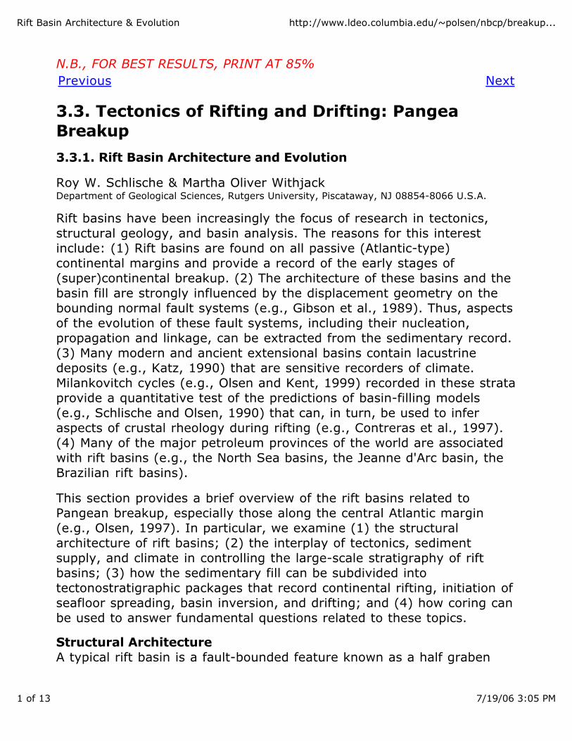
(Fig. 3.3.1.1a). In a cross section oriented perpendicular to the boundaryfault (transverse section), the half graben has a triangular geometry(Fig. 3.3.1.1b). The three sides of the triangle are the border fault, therift-onset unconformity between prerift and synrift rocks, and thepostrift unconformity between synrift and postrift rocks (or, for modernrifts, the present-day depositional surface). Within the triangular wedgeof synrift units, stratal boundaries rotate from being subparallel to therift-onset unconformity to being subparallel to the postrift unconformity.This fanning geometry, along with thickening of synrift units toward theboundary fault, are produced by syndepositional faulting. Core from theNewark basin confirms the thickening relationships (see Section 3.3.2).Synrift strata commonly onlap prerift rocks. In a cross section orientedparallel to the boundary fault (longitudinal section), the basin has asynclinal geometry (Fig. 3.3.1.1c), although more complicated geometries are associated with segmented boundary fault systems (e.g.,Schlische, 1993; Schlische and Anders, 1996; Morley, 1999).
Figure 3.3.1.1. Geometry of a simple half graben. (a) Map-viewgeometry. (b) Geometry along a cross section oriented perpendicular to the boundary fault, showing wedge-shaped basin in which synriftstrata exhibit a fanning geometry, thicken toward the boundary fault,and onlap prerift rocks. (c) Geometry along a cross section orientedparallel to the boundary fault, showing syncline-shaped basin in whichsynrift strata thin away from the center of the basin and onlap preriftrocks.
The half-graben geometry described above is directly controlled by thedeformation (displacement) field surrounding the boundary fault system
Rift Basin Architecture & Evolution http://www.ldeo.columbia.edu/~polsen/nbcp/breakup...
3 of 13 7/19/06 3:05 PM
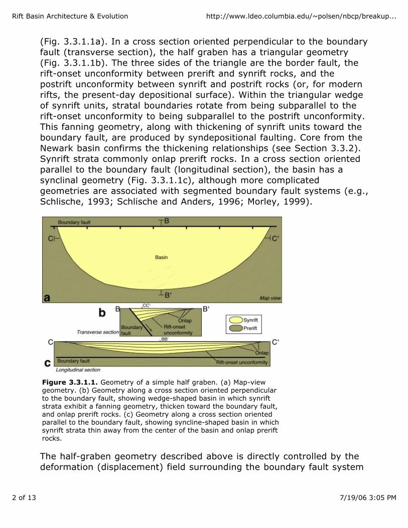
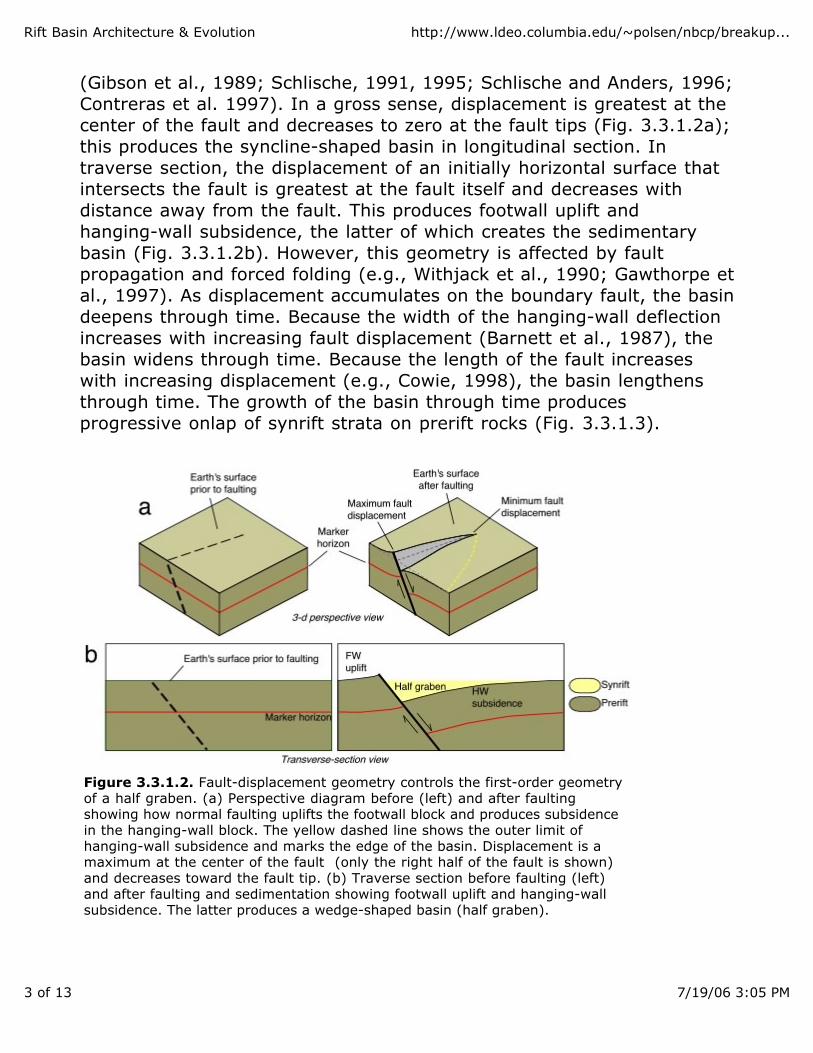
(Gibson et al., 1989; Schlische, 1991, 1995; Schlische and Anders, 1996;Contreras et al. 1997). In a gross sense, displacement is greatest at thecenter of the fault and decreases to zero at the fault tips (Fig. 3.3.1.2a);this produces the syncline-shaped basin in longitudinal section. Intraverse section, the displacement of an initially horizontal surface thatintersects the fault is greatest at the fault itself and decreases withdistance away from the fault. This produces footwall uplift and hanging-wall subsidence, the latter of which creates the sedimentarybasin (Fig. 3.3.1.2b). However, this geometry is affected by faultpropagation and forced folding (e.g., Withjack et al., 1990; Gawthorpe etal., 1997). As displacement accumulates on the boundary fault, the basindeepens through time. Because the width of the hanging-wall deflectionincreases with increasing fault displacement (Barnett et al., 1987), thebasin widens through time. Because the length of the fault increaseswith increasing displacement (e.g., Cowie, 1998), the basin lengthensthrough time. The growth of the basin through time producesprogressive onlap of synrift strata on prerift rocks (Fig. 3.3.1.3).
Figure 3.3.1.2. Fault-displacement geometry controls the first-order geometryof a half graben. (a) Perspective diagram before (left) and after faultingshowing how normal faulting uplifts the footwall block and produces subsidencein the hanging-wall block. The yellow dashed line shows the outer limit ofhanging-wall subsidence and marks the edge of the basin. Displacement is amaximum at the center of the fault (only the right half of the fault is shown)and decreases toward the fault tip. (b) Traverse section before faulting (left)and after faulting and sedimentation showing footwall uplift and hanging-wallsubsidence. The latter produces a wedge-shaped basin (half graben).
Rift Basin Architecture & Evolution http://www.ldeo.columbia.edu/~polsen/nbcp/breakup...
4 of 13 7/19/06 3:05 PM
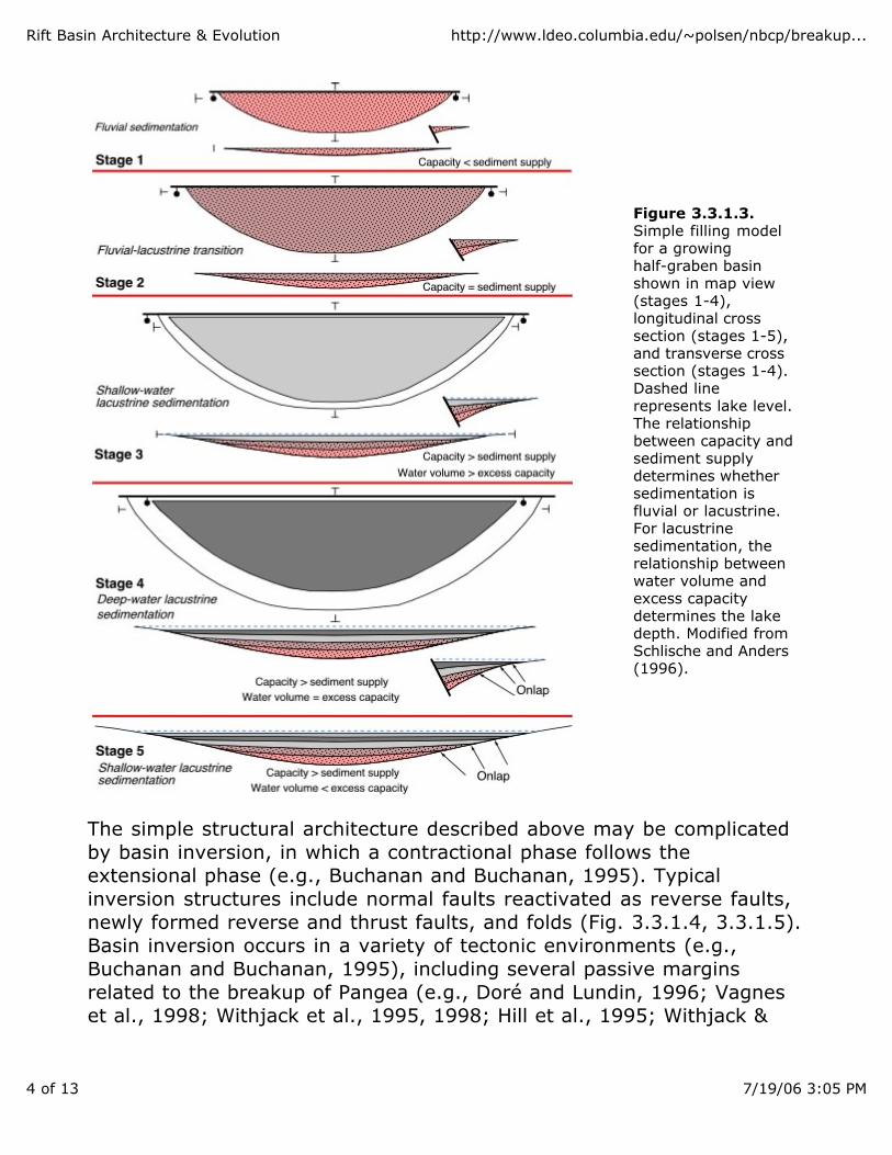
Figure 3.3.1.3.Simple filling model for a growing half-graben basinshown in map view (stages 1-4), longitudinal cross section (stages 1-5),and transverse cross section (stages 1-4). Dashed line represents lake level.The relationship between capacity and sediment supply determines whethersedimentation is fluvial or lacustrine. For lacustrine sedimentation, therelationship between water volume and excess capacity determines the lakedepth. Modified from Schlische and Anders (1996).
The simple structural architecture described above may be complicatedby basin inversion, in which a contractional phase follows theextensional phase (e.g., Buchanan and Buchanan, 1995). Typical inversion structures include normal faults reactivated as reverse faults,newly formed reverse and thrust faults, and folds (Fig. 3.3.1.4, 3.3.1.5).Basin inversion occurs in a variety of tectonic environments (e.g.,Buchanan and Buchanan, 1995), including several passive marginsrelated to the breakup of Pangea (e.g., Doré and Lundin, 1996; Vagneset al., 1998; Withjack et al., 1995, 1998; Hill et al., 1995; Withjack &
Rift Basin Architecture & Evolution http://www.ldeo.columbia.edu/~polsen/nbcp/breakup...
5 of 13 7/19/06 3:05 PM
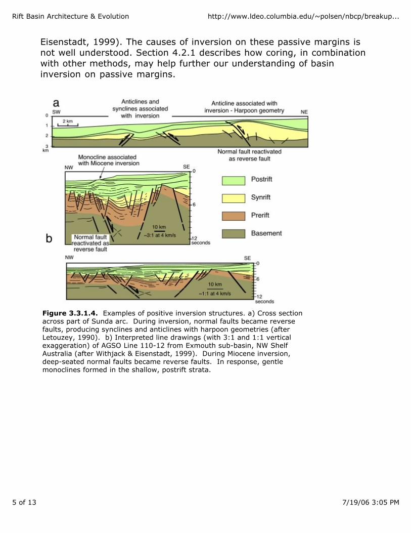
Eisenstadt, 1999). The causes of inversion on these passive margins isnot well understood. Section 4.2.1 describes how coring, in combinationwith other methods, may help further our understanding of basininversion on passive margins.
Figure 3.3.1.4. Examples of positive inversion structures. a) Cross sectionacross part of Sunda arc. During inversion, normal faults became reversefaults, producing synclines and anticlines with harpoon geometries (afterLetouzey, 1990). b) Interpreted line drawings (with 3:1 and 1:1 verticalexaggeration) of AGSO Line 110-12 from Exmouth sub-basin, NW ShelfAustralia (after Withjack & Eisenstadt, 1999). During Miocene inversion,deep-seated normal faults became reverse faults. In response, gentlemonoclines formed in the shallow, postrift strata.
Rift Basin Architecture & Evolution http://www.ldeo.columbia.edu/~polsen/nbcp/breakup...
6 of 13 7/19/06 3:05 PM
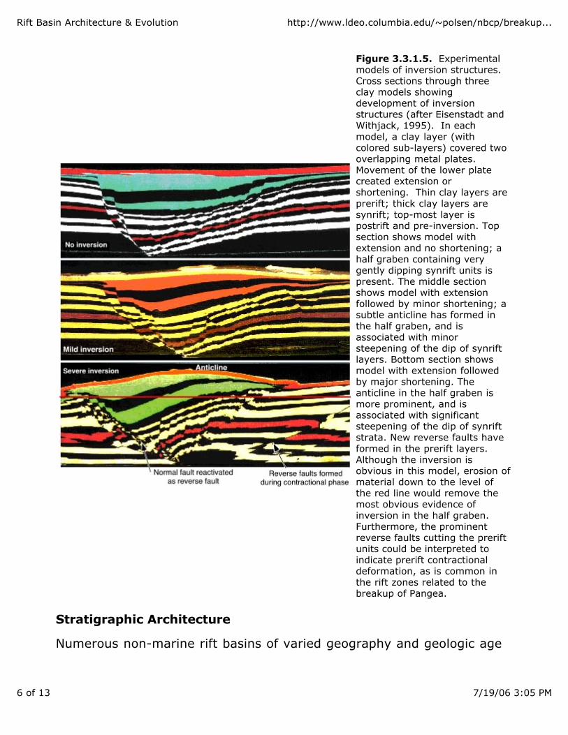
Figure 3.3.1.5. Experimental models of inversion structures. Cross sections through three clay models showing development of inversionstructures (after Eisenstadt and Withjack, 1995). In eachmodel, a clay layer (withcolored sub-layers) covered two overlapping metal plates. Movement of the lower plate created extension orshortening. Thin clay layers areprerift; thick clay layers are synrift; top-most layer ispostrift and pre-inversion. Top section shows model with extension and no shortening; ahalf graben containing very gently dipping synrift units ispresent. The middle section shows model with extension followed by minor shortening; asubtle anticline has formed in the half graben, and is associated with minorsteepening of the dip of synrift layers. Bottom section showsmodel with extension followed by major shortening. The anticline in the half graben ismore prominent, and is associated with significant steepening of the dip of synriftstrata. New reverse faults have formed in the prerift layers.Although the inversion is obvious in this model, erosion of material down to the level ofthe red line would remove the most obvious evidence ofinversion in the half graben. Furthermore, the prominent reverse faults cutting the preriftunits could be interpreted to indicate prerift contractionaldeformation, as is common in the rift zones related to the breakup of Pangea.
Stratigraphic Architecture
Numerous non-marine rift basins of varied geography and geologic age
Rift Basin Architecture & Evolution http://www.ldeo.columbia.edu/~polsen/nbcp/breakup...
7 of 13 7/19/06 3:05 PM
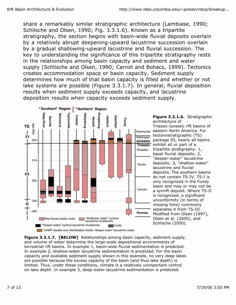
share a remarkably similar stratigraphic architecture (Lambiase, 1990;Schlische and Olsen, 1990; Fig. 3.3.1.6). Known as a tripartite stratigraphy, the section begins with basin-wide fluvial deposits overlainby a relatively abrupt deepening-upward lacustrine succession overlainby a gradual shallowing-upward lacustrine and fluvial succession. Thekey to understanding the significance of this tripartite stratigraphy restsin the relationships among basin capacity and sediment and watersupply (Schlische and Olsen, 1990; Carroll and Bohacs, 1999). Tectonicscreates accommodation space or basin capacity. Sediment supplydetermines how much of that basin capacity is filled and whether or notlake systems are possible (Figure 3.3.1.7). In general, fluvial depositionresults when sediment supply exceeds capacity, and lacustrinedeposition results when capacity exceeds sediment supply.
Figure 3.3.1.6. Stratigraphic architecture of Triassic-Jurassic rift basins ofeastern North America. For tectonostratigraphic (TS) package III, nearly all basinsexhibit all or part of a tripartite stratigraphy: 1,basal fluvial deposits; 2, "deeper-water" lacustrine deposits; 3, "shallow-water"lacustrine and fluvial deposits. The southern basins do not contain TS-IV. TS-I isonly recognized in the Fundy basin and may or may not be a synrift deposit. Where TS-IIis recognized, a significant unconformity (in terms ofmissing time) commonly separates it from TS-III. Modified from Olsen (1997),Olsen et al. (2000), and Schlische (2000).
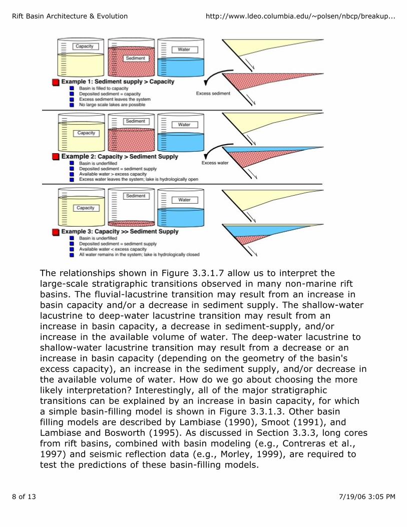
Figure 3.3.1.7. [BELOW] Relationships among basin capacity, sediment supply,and volume of water determine the large-scale depositional environments ofterrestrial rift basins. In example 1, basin-wide fluvial sedimentation is predicted.In example 2, shallow-water lacustrine sedimentation is predicted. For the basincapacity and available sediment supply shown in this example, no very deep lakesare possible because the excess capacity of the basin (and thus lake depth) islimited. Thus, under these conditions, climate is a relatively unimportant controlon lake depth. In example 3, deep-water lacustrine sedimentation is predicted.
Rift Basin Architecture & Evolution http://www.ldeo.columbia.edu/~polsen/nbcp/breakup...
8 of 13 7/19/06 3:05 PM
The relationships shown in Figure 3.3.1.7 allow us to interpret thelarge-scale stratigraphic transitions observed in many non-marine riftbasins. The fluvial-lacustrine transition may result from an increase inbasin capacity and/or a decrease in sediment supply. The shallow-waterlacustrine to deep-water lacustrine transition may result from an increase in basin capacity, a decrease in sediment-supply, and/orincrease in the available volume of water. The deep-water lacustrine toshallow-water lacustrine transition may result from a decrease or anincrease in basin capacity (depending on the geometry of the basin'sexcess capacity), an increase in the sediment supply, and/or decrease inthe available volume of water. How do we go about choosing the morelikely interpretation? Interestingly, all of the major stratigraphictransitions can be explained by an increase in basin capacity, for whicha simple basin-filling model is shown in Figure 3.3.1.3. Other basinfilling models are described by Lambiase (1990), Smoot (1991), andLambiase and Bosworth (1995). As discussed in Section 3.3.3, long coresfrom rift basins, combined with basin modeling (e.g., Contreras et al.,1997) and seismic reflection data (e.g., Morley, 1999), are required totest the predictions of these basin-filling models.
Rift Basin Architecture & Evolution http://www.ldeo.columbia.edu/~polsen/nbcp/breakup...
9 of 13 7/19/06 3:05 PM
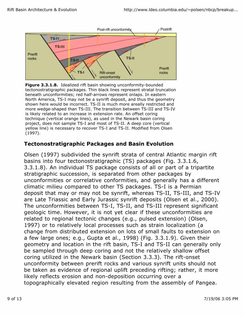
Figure 3.3.1.8. Idealized rift basin showing unconformity-boundedtectonostratigraphic packages. Thin black lines represent stratal truncationbeneath unconformities; red half-arrows represent onlaps. In eastern North America, TS-I may not be a synrift deposit, and thus the geometryshown here would be incorrect. TS-II is much more areally restricted andmore wedge-shaped than TS-III. The transition between TS-III and TS-IVis likely related to an increase in extension rate. An offset coringtechnique (vertical orange lines), as used in the Newark basin coringproject, does not sample TS-I and most of TS-II. A deep core (verticalyellow line) is necessary to recover TS-I and TS-II. Modified from Olsen(1997).
Tectonostratigraphic Packages and Basin Evolution
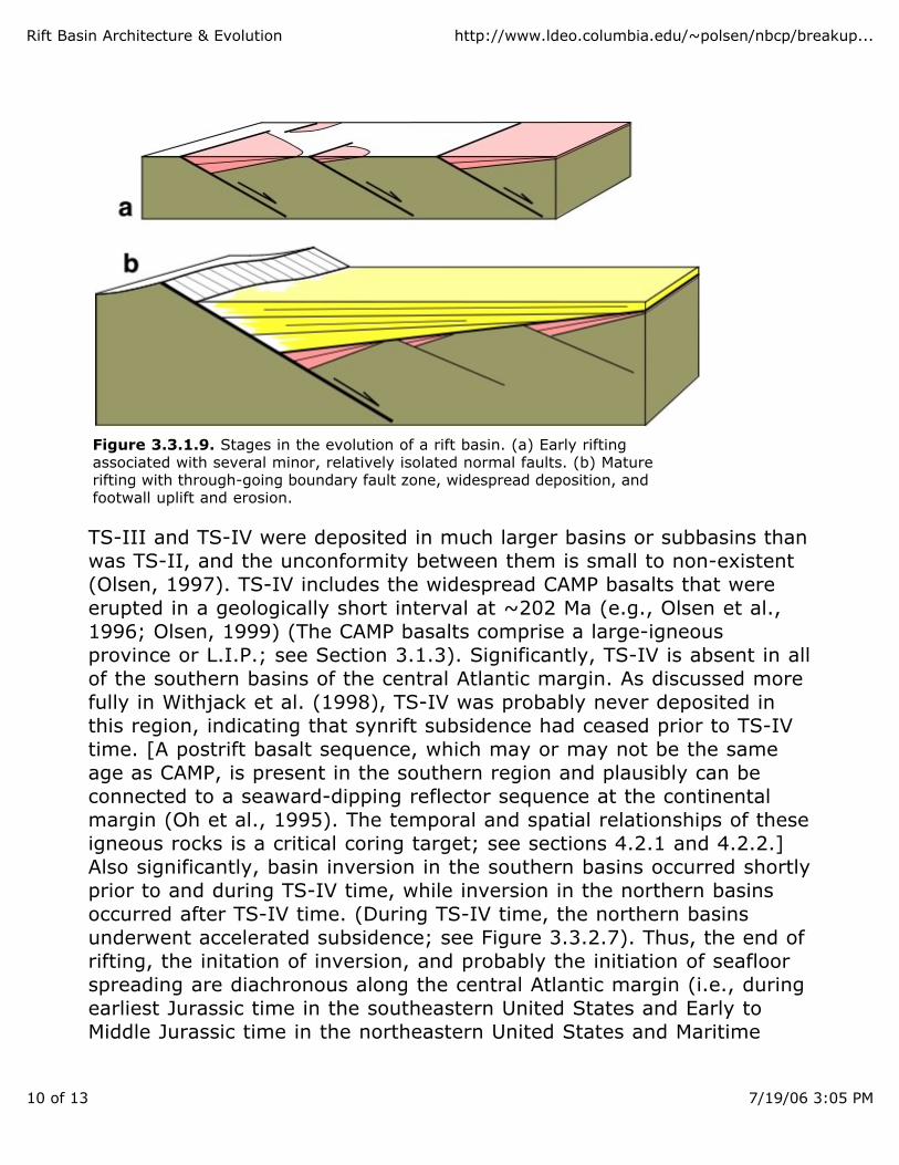
Olsen (1997) subdivided the synrift strata of central Atlantic margin riftbasins into four tectonostratigraphic (TS) packages (Fig. 3.3.1.6,3.3.1.8). An individual TS package consists of all or part of a tripartitestratigraphic succession, is separated from other packages byunconformities or correlative conformities, and generally has a differentclimatic milieu compared to other TS packages. TS-I is a Permian deposit that may or may not be synrift, whereas TS-II, TS-III, and TS-IVare Late Triassic and Early Jurassic synrift deposits (Olsen et al., 2000). The unconformities between TS-I, TS-II, and TS-III represent significantgeologic time. However, it is not yet clear if these unconformities arerelated to regional tectonic changes (e.g., pulsed extension) (Olsen, 1997) or to relatively local processes such as strain localization (achange from distributed extension on lots of small faults to extension ona few large ones; e.g., Gupta et al., 1998) (Fig. 3.3.1.9). Given theirgeometry and location in the rift basin, TS-I and TS-II can generally onlybe sampled through deep coring and not the relatively shallow offsetcoring utilized in the Newark basin (Section 3.3.3). The rift-onsetunconformity between prerift rocks and various synrift units should notbe taken as evidence of regional uplift preceding rifting; rather, it morelikely reflects erosion and non-deposition occurring over atopographically elevated region resulting from the assembly of Pangea.
Rift Basin Architecture & Evolution http://www.ldeo.columbia.edu/~polsen/nbcp/breakup...
10 of 13 7/19/06 3:05 PM
Figure 3.3.1.9. Stages in the evolution of a rift basin. (a) Early riftingassociated with several minor, relatively isolated normal faults. (b) Maturerifting with through-going boundary fault zone, widespread deposition, andfootwall uplift and erosion.
TS-III and TS-IV were deposited in much larger basins or subbasins thanwas TS-II, and the unconformity between them is small to non-existent(Olsen, 1997). TS-IV includes the widespread CAMP basalts that wereerupted in a geologically short interval at ~202 Ma (e.g., Olsen et al.,1996; Olsen, 1999) (The CAMP basalts comprise a large-igneous province or L.I.P.; see Section 3.1.3). Significantly, TS-IV is absent in allof the southern basins of the central Atlantic margin. As discussed morefully in Withjack et al. (1998), TS-IV was probably never deposited inthis region, indicating that synrift subsidence had ceased prior to TS-IVtime. [A postrift basalt sequence, which may or may not be the sameage as CAMP, is present in the southern region and plausibly can beconnected to a seaward-dipping reflector sequence at the continentalmargin (Oh et al., 1995). The temporal and spatial relationships of theseigneous rocks is a critical coring target; see sections 4.2.1 and 4.2.2.]Also significantly, basin inversion in the southern basins occurred shortlyprior to and during TS-IV time, while inversion in the northern basinsoccurred after TS-IV time. (During TS-IV time, the northern basinsunderwent accelerated subsidence; see Figure 3.3.2.7). Thus, the end ofrifting, the initation of inversion, and probably the initiation of seafloorspreading are diachronous along the central Atlantic margin (i.e., duringearliest Jurassic time in the southeastern United States and Early toMiddle Jurassic time in the northeastern United States and Maritime
Rift Basin Architecture & Evolution http://www.ldeo.columbia.edu/~polsen/nbcp/breakup...
11 of 13 7/19/06 3:05 PM
Canada) (Withjack et al., 1998). Coring, field analysis, andseismic-reflection profiles of synrift and immediately overlying postriftdeposits and the structures formed in them, are necessary to clarify theimportant events occurring at the rift-drift transition.
The inferred diachronous initiation of seafloor spreading along thepresent-day margin of the central North America Ocean is part of largertrend that reflects the progressive dismemberment of Pangea. As theNorth Atlantic Ocean continued to develop, seafloor spreading propagated northward. For example, seafloor spreading between theGrand Banks and southwestern Europe began during the EarlyCretaceous (e.g., Srivastava and Tapscott, 1986); seafloor spreadingbetween Labrador and western Greenland began during the earlyTertiary (anomaly 27N) (e.g., Chalmers, et al., 1993); whereas seafloorspreading between eastern Greenland and northwestern Europe beganslightly later during the early Tertiary (anomaly 24R) (e.g., Talwani andEldholm, 1977; Hinz et al., 1993).
References:
Barnett, J. A. M., Mortimer, J., Rippon, J. H., Walsh, J. J., and Watterson, J., 1987,Displacement geometry in the volume containing a single normal fault: American Association ofPetroleum Geologists Bulletin, v. 71, p. 925-937.
Buchanan, J. G., and Buchanan, P. G., eds., 1995, Basin Inversion: Geological Society ofLondon Special Publication 88, 596 p. Carroll, A.R., and Bohacs, K.M., 1999, Stratigraphic classification of ancient lakes: Balancingtectonic and climatic controls: Geology, v. 27, p. 99-102.
Chalmers, J. A., Pulvertaft, C. R., Christiansen, F. G., Laresen, H. C.,Laursen, K. H., andOttesen, T. G., 1993, The southern West Greenland continental margin: Rifting history, basindevelopment, and petroleum potential, in Parker, J. R., ed., Petroleum Geology of NorthwestEurope, Proceedings of the 4th Conference: Geological Society of London, v. 2, p. 915-931.
Contreras, J., Scholz, C. H., King, G. C. P., 1997, A general model of rift basin evolution:constraints of first order stratigraphic observations: Journal of Geophysical Research, v. 102, p.7673-7690.
Cowie, P. A., 1998, Normal fault growth in three-dimensions in continental and oceanic crust, inFaulting and Magmatism at Mid-Ocean Ridges: Geophysical Monograph 106, AmericanGeophysical Union, p. 325-348.
Dore, A. G., and Lundin, E. R., 1996, Cenozoic compressional structures on the NE Atlanticmargin: nature, origin, and potential signficance for hydrocarbon exploration: PetroleumGeoscience, v. 2, p. 299-311.
Eisenstadt, G., and Withjack, M. O., 1995, Estimating inversion: results from clay models, inBuchanan, J. G., and Buchanan, P. G., eds., 1995, Basin Inversion: Geological Society ofLondon Special Publication 88, p. 119-136.
Gawthorpe, R.L., Sharp, I., Underhill, J.R., and Gupta, S., 1997, Linked sequence stratigraphic
Rift Basin Architecture & Evolution http://www.ldeo.columbia.edu/~polsen/nbcp/breakup...
12 of 13 7/19/06 3:05 PM
and structural evolution of propagating normal faults: Geology, v. 25, p. 795-798.
Gibson, J. R., Walsh, J. J., and Watterson, J., 1989, Modelling of bed contours andcross-sections adjacent to planar normal faults: Journal of Structural Geology, v. 11, p.317-328.
Gupta, S., Cowie, P. A., Dawers, N. H., and Underhill, J. R., 1998, A mechanism to explainrift-basin subsidence and stratigraphic patterns through fault-array evolution: Geology, v. 26, p.595-598.
Hill, K. C., Hill, K. A., Cooper, G. T., O'Sullivan, A. J., O'Sullivan, P. B., and Richardson, M. J.,1995, Inversion around the Bass basin, SE Australia, in Buchanan, J.G., and Buchanan, P.G.,eds., 1995, Basin Inversion: Geological Society of London Special Publication 88, p. 525-548.
Hinz, K., Eldholm, O., Block, M., and Skogseid, J., 1993, Evolution of North Atlantic volcaniccontinental margins, in Parker, J. R., ed., Petroleum Geology of Northwest Europe, Proceedingsof the 4th Conference: Geological Society of London, v. 2, p. 901-913.
Katz, B. J., ed., 1990, Lacustrine basin exploration--case studies and modern analogs: AAPGMemoir 50, 340 p. Lambiase, J.J., 1990, A model for tectonic control of lacustrine stratigraphic sequences incontinental rift basins, in Katz, B.J., ed., Lacustrine Exploration: Case Studies and ModernAnalogues: AAPG Memoir 50, p. 265-276.
Lambiase, J. J., and Bosworth, W., 1995, Structural controls on sedimentation in continentalrifts, in Lambiase, J.J., ed., Hydrocarbon habitat in rift basins: Geological Society SpecialPublication 80, p. 117-144.
Morley, C. K., 1999, Patterns of displacement along large normal faults: Implications for basinevolution and fault propagation, based on examples from East Africa: AAPG Bulletin, v. 83, p.613-634.
Oh, J., Austin, J. A., Jr., Phillips, J. D., Coffin, M. F., and Stoffa, P. L., 1995, Seaward-dippingreflectors offshore the southeastern United States: Seismic evidence for extensive volcanismaccompanying sequential formation of the Carolina trough and Blake Plateau basin: Geology, v.23, p. 9-12.
Olsen, P. E., Schlische, R. W., and Fedosh, M. S., 1996, 580 kyr duration of the Early Jurassicflood basalt event in eastern North America estimated using Milankovitch cyclostratigraphy, inMorales, M., ed., The Continental Jurassic: Museum of Northern Arizona Bulletin 60, p. 11-22.
Olsen, P. E., 1997, Stratigraphic record of the early Mesozoic breakup of Pangea in theLaurasia-Gondwana rift system: Annual Reviews of Earth and Planetary Science, v. 25, p.337-401.
Olsen, P. E., and Kent, D. V., 1999, Long-period Milankovitch cycles from the Late Triassic andEarly Jurassic of eastern North America and their implications for the calibration of the earlyMesozoic time scale and the long-term behavior of the planets. Transactions, Royal Society ofLondon, Series A, v. 357, p. 1761-1786.
Olsen, P. E., 1999, Giant lava flows, mass extinctions, and mantle plumes [perspective onMarzoli, et al.]: Science, v. 284, p. 604 - 605.
Rosendahl, B. R., 1987, Architecture of continental rifts with special reference to East Africa:Annual Review of Earth and Planetary Science, v. 15, p. 445-503.
Rift Basin Architecture & Evolution http://www.ldeo.columbia.edu/~polsen/nbcp/breakup...
13 of 13 7/19/06 3:05 PM
Schlische, R. W., 1991, Half-graben filling models: New constraints on continental extensionalbasin development: Basin Research, v. 3, p. 123-141.
Schlische, R. W., 1993, Anatomy and evolution of the Triassic-Jurassic continental rift system,eastern North America: Tectonics, v. 12, p. 1026-1042.
Schlische, R. W., 1995, Geometry and origin of fault-related folds in extensional settings:American Association of Petroleum Geologists Bulletin, v. 79, p. 1661-1678.
Schlische, R. W., 2000, Progress in understanding the structural geology, basin evolution, andtectonic history of the eastern North American rift system, in LeTourneau, P.M., and Olsen, P.E.,eds., Aspects of Triassic-Jurassic Rift Basin Geoscience: New York, Columbia University Press, inpress.
Schlische, R. W., and Anders, M. H., 1996, Stratigraphic effects and tectonic implications of thegrowth of normal faults and extensional basins, in Beratan, K. K., ed., Reconstructing theStructural History of Basin and Range Extension Using Sedimentology and Stratigraphy: GSASpecial Paper 303, p. 183-203.
Schlische, R. W., and Olsen, P. E., 1990, Quantitative filling model for continental extensionalbasins with applications to early Mesozoic rifts of eastern North America: Journal of Geology, v.98, p. 135-155.
Smoot, J. P., 1991, Sedimentary facies and depositional environments of early Mesozoic NewarkSupergroup basins, eastern North America: Palaeogeography, Palaeoclimatology, Palaeoecology,v. 84, p. 369-423.
Srivastava, S. P., and Tapscott, C. R., 1986, Plate kinematics of the North Atlantic, in Vogt, P.R., and Tucholke, B. E., eds., The Geology of North America, v. M., The Western North AtlanticRegion: Geological Society of America, p. 379-404.
Talwani, M., and Eldholm, O., 1977, Evolution of the Norwegian-Greenland Sea: GSA Bulletin,v. 88, p. 969-999.
Vågnes, E., Gabrielsen, R. H., and Haremo, P., 1998, Late Cretaceous-Cenozoic intraplatecontractional deformation at the Norwegian continental shelf: timing, magnitude and regionalimplications: Tectonophysics, v. 300, p. 29-46.
Withjack, M.O., Olson, J., and Peterson, E., 1990, Experimental models of extensional forcedfolds: AAPG Bulletin, v. 74, p. 1038-1054.
Withjack, M. O. and Eisenstadt, G., 1999, Structural history of the Northwest Shelf, Australia --an integrated geological, geophysical and experimental approach: AAPG Annual MeetingAbstract, v. 8, p. A151.
Withjack, M.O., Olsen, P.E., and Schlische, R.W., 1995, Tectonic evolution of the Fundy riftbasin, Canada: Evidence of extension and shortening during passive margin development:Tectonics, v. 14, p. 390-405.
Withjack, M.O., Schlische, R.W., and Olsen, P.E., 1998, Diachronous rifting, drifting, andinversion on the passive margin of central eastern North America: An analog for other passivemargins: AAPG Bulletin, v. 82, p. 817-835.
Previous Next