Embed Size (px)
Citation preview
39% Krill Katana S
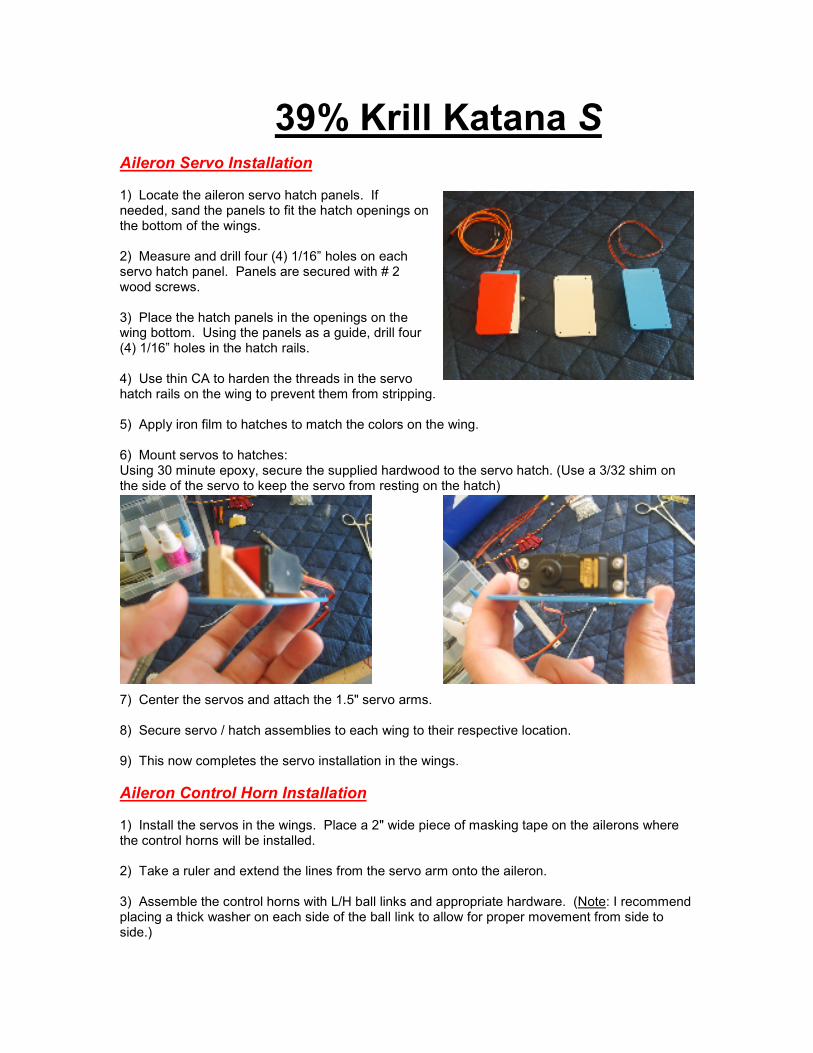
Aileron Servo Installation 1) Locate the aileron servo hatch panels. If needed, sand the panels to fit the hatch openings on the bottom of the wings. 2) Measure and drill four (4) 1/16” holes on each servo hatch panel. Panels are secured with # 2 wood screws. 3) Place the hatch panels in the openings on the wing bottom. Using the panels as a guide, drill four (4) 1/16” holes in the hatch rails. 4) Use thin CA to harden the threads in the servo hatch rails on the wing to prevent them from stripping. 5) Apply iron film to hatches to match the colors on the wing. 6) Mount servos to hatches: Using 30 minute epoxy, secure the supplied hardwood to the servo hatch. (Use a 3/32 shim on the side of the servo to keep the servo from resting on the hatch)
7) Center the servos and attach the 1.5" servo arms. 8) Secure servo / hatch assemblies to each wing to their respective location. 9) This now completes the servo installation in the wings.
Aileron Control Horn Installation 1) Install the servos in the wings. Place a 2" wide piece of masking tape on the ailerons where the control horns will be installed. 2) Take a ruler and extend the lines from the servo arm onto the aileron. 3) Assemble the control horns with L/H ball links and appropriate hardware. (Note: I recommend placing a thick washer on each side of the ball link to allow for proper movement from side to side.)
4) Place the control horn assembly on the aileron and line it up in with the servo arm. Mark the servo horn location on the aileron. (Note: Be certain to measure back at least .070" from the lip of the aileron.) 5) Use a # 11 hobby knife to cut away the 'skin' of the aileron. Then use a Dremel® tool to remove the remaining material in the aileron. (Note: The cutout depth should only be as deep as is needed for the control horn to sit properly, roughly .060" deep.) 6) When satisfied with the fit, use 30 minute epoxy (mixed with milled fiberglass), BVM Aeropoxy®, or equivalent, to mount the control horn assembly. (Note: Be sure to 'scuff' the control horns before installation.) 7) This now completes the aileron control horn installation.
Note: See Elevator Control Horn Installation for images.
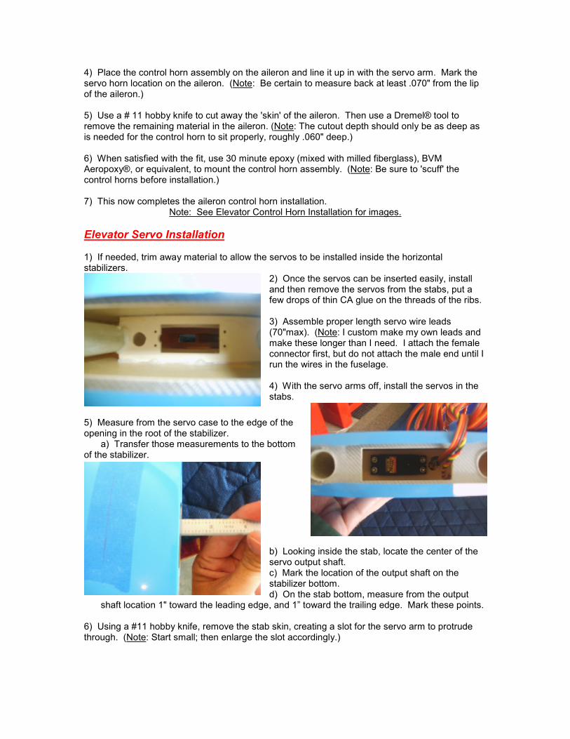
Elevator Servo Installation 1) If needed, trim away material to allow the servos to be installed inside the horizontal stabilizers.
2) Once the servos can be inserted easily, install and then remove the servos from the stabs, put a few drops of thin CA glue on the threads of the ribs. 3) Assemble proper length servo wire leads (70"max). (Note: I custom make my own leads and make these longer than I need. I attach the female connector first, but do not attach the male end until I run the wires in the fuselage. 4) With the servo arms off, install the servos in the stabs.
5) Measure from the servo case to the edge of the opening in the root of the stabilizer. a) Transfer those measurements to the bottom of the stabilizer.
b) Looking inside the stab, locate the center of the servo output shaft. c) Mark the location of the output shaft on the stabilizer bottom. d) On the stab bottom, measure from the output
shaft location 1" toward the leading edge, and 1” toward the trailing edge. Mark these points. 6) Using a #11 hobby knife, remove the stab skin, creating a slot for the servo arm to protrude through. (Note: Start small; then enlarge the slot accordingly.)
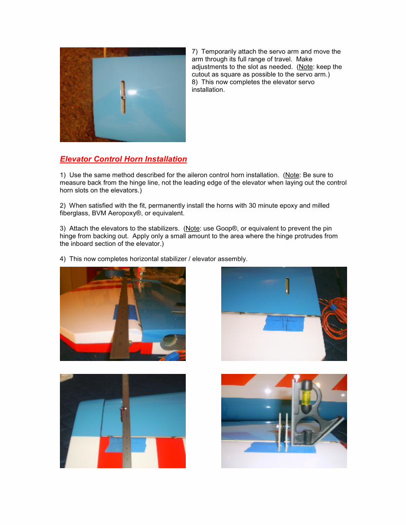
7) Temporarily attach the servo arm and move the arm through its full range of travel. Make adjustments to the slot as needed. (Note: keep the cutout as square as possible to the servo arm.) 8) This now completes the elevator servo installation.
Elevator Control Horn Installation 1) Use the same method described for the aileron control horn installation. (Note: Be sure to measure back from the hinge line, not the leading edge of the elevator when laying out the control horn slots on the elevators.) 2) When satisfied with the fit, permanently install the horns with 30 minute epoxy and milled fiberglass, BVM Aeropoxy®, or equivalent. 3) Attach the elevators to the stabilizers. (Note: use Goop®, or equivalent to prevent the pin hinge from backing out. Apply only a small amount to the area where the hinge protrudes from the inboard section of the elevator.) 4) This now completes horizontal stabilizer / elevator assembly.
Setting the Wing Incidence CAUTION: DO NOT ATTEMPT TO SET THE WING INCIDENCE WITH ONLY ONE WING ON
THE FUSELAGE - ALWAYS INSTAL BOTH WINGS WHEN SETTING THE WING INCIDENCE.
1) Install both wings on the fuselage with incidence meters in place. 2) Use the hatch line as a reference; level the fuselage at 0 degrees. 3) Use 1" long 6mm threaded screws to transfer the wing-bolt hole locations to the fuselage.
a) Thread the screws in to the wing-root until the tip of the screws protrude just beyond the wing-root.
b) Use a black magic marker (lipstick also works well) and color the end of the screw. 4) Set both wing panels at 0 degrees. a) Use masking tape to hold one wing in position against the fuselage.
b) Level the opposite wing (with the 1" screws) at 0 degrees; gently push the wing against the fuselage so that the screws transfer a mark from the painted tips.
(Note: It is good to have a helper on this step to hold the wings in position while you set the incidence.) 5) Remove the one wing and drill the holes in the fuse to accept the wing bolts. Slide the wing back onto the fuse and insert wing bolts. The wing should be pretty close to 0 degrees. Repeat steps three (3) and four (4) for the other wing. 6) With both wings now installed, you can fine tune the incidence with the supplied phenolic washers to secure in the wing at 0 degrees.
a) With the incidence meters on the wing, verify that the wing and fuselage are still at 0 degrees. b) Glue the front washer in first; verify that the wing and fuselage are still at 0 degrees (Note: if you don’t get exactly 0 degrees after the front washer is glued in, you can finitely raise or lower the TE of the wing to achieve the proper wing setting).
c) Glue the aft washer in place. 7) Make a hole in the fuselage sides to allow the servo wires to pass through. 8) This now completes the wing incidence.
Securing the Stabilizers to the Fuselage 1) Place the stabs upside down and install the aluminum tubes. With a straight edge lying across the stabilizers tip to tip, draw a straight line onto the stabs in conjunction with the aluminum tubes. 2) Verify how far each aluminum tube will be inserted into each stabilizer by fitting the stabilizers on the fuselage. 3) Remove the stabs and tubes from the airframe. Working one tube at a time, insert one tube to the desired length into one of the stabilizers. 4) Hold the stabilizer up to a bright light and locate the hard point in the stab where the retaining bolt will be located. 5) When satisfied with the position of the aluminum tube, drill a hole on the bottom side of the stab into the aluminum tube. Before removing the tube, take a 4-40 (or 6-32) allen head bolt and thread into the hole you just drilled.
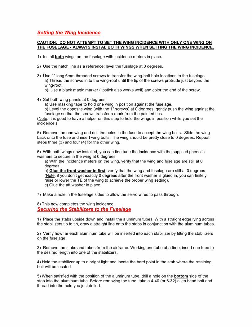
6) Remove the bolt and slide the aluminum tube out of the stab. Remove any 'burrs' that may impede re-installation of the tube. Repeat this procedure for the second tube on the same stabilizer. 7) Re-install the aluminum tubes in the stab and secure with bolts. Slide the assembled stab onto the fuse. Take the second stab and hold up next to a bright light and locate the hard point. 8) Flip the plane over so that it is upside down.
a) Measure the length of the protruding aluminum tubes and transfer the end location of each tube onto the stab bottom. b) Measure inboard from the tube-end marks 3/8" to 1/2"; mark for the retention-bolt holes.
9) Ensure that both stabilizers are pushed snuggly against the fuselage.
a) Drill holes for the retention bolts at locations you marked. b) Thread your retaining bolt into these holes and then disassemble that stabilizer. (Note: be sure to label where each tube is to be reinstalled.)
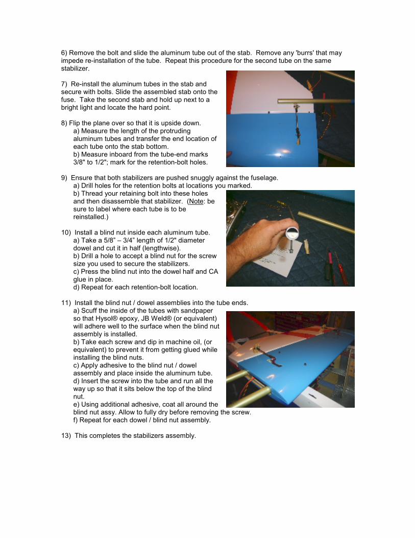
10) Install a blind nut inside each aluminum tube.
a) Take a 5/8” – 3/4” length of 1/2" diameter dowel and cut it in half (lengthwise). b) Drill a hole to accept a blind nut for the screw size you used to secure the stabilizers. c) Press the blind nut into the dowel half and CA glue in place. d) Repeat for each retention-bolt location.
11) Install the blind nut / dowel assemblies into the tube ends.
a) Scuff the inside of the tubes with sandpaper so that Hysol® epoxy, JB Weld® (or equivalent) will adhere well to the surface when the blind nut assembly is installed. b) Take each screw and dip in machine oil, (or equivalent) to prevent it from getting glued while installing the blind nuts. c) Apply adhesive to the blind nut / dowel assembly and place inside the aluminum tube. d) Insert the screw into the tube and run all the way up so that it sits below the top of the blind nut. e) Using additional adhesive, coat all around the blind nut assy. Allow to fully dry before removing the screw. f) Repeat for each dowel / blind nut assembly.
13) This completes the stabilizers assembly.
Landing Gear and Tailwheel Installation 1) The landing gear is held in place with three (3) bolts and secured by three (3) blind nuts installed in ply doublers. Press the blind nuts into the supplied plywood doublers. 2) Place the fuselage upside down on the work table, and check to see if the gear will fit in the channel of the fuselage. If required, remove material from the gear to allow a proper fit. 3) Locate the center of the landing gear:
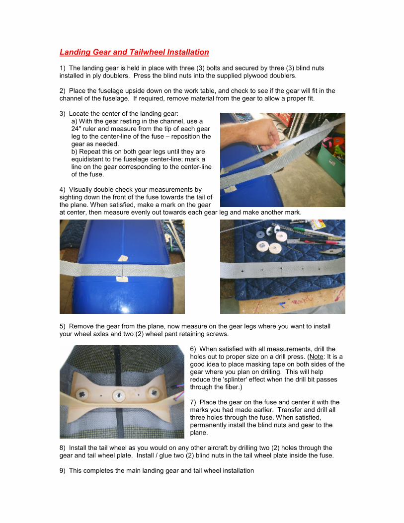
a) With the gear resting in the channel, use a 24" ruler and measure from the tip of each gear leg to the center-line of the fuse – reposition the gear as needed. b) Repeat this on both gear legs until they are equidistant to the fuselage center-line; mark a line on the gear corresponding to the center-line of the fuse.
4) Visually double check your measurements by sighting down the front of the fuse towards the tail of the plane. When satisfied, make a mark on the gear at center, then measure evenly out towards each gear leg and make another mark.
5) Remove the gear from the plane, now measure on the gear legs where you want to install your wheel axles and two (2) wheel pant retaining screws.
6) When satisfied with all measurements, drill the holes out to proper size on a drill press. (Note: It is a good idea to place masking tape on both sides of the gear where you plan on drilling. This will help reduce the 'splinter' effect when the drill bit passes through the fiber.) 7) Place the gear on the fuse and center it with the marks you had made earlier. Transfer and drill all three holes through the fuse. When satisfied, permanently install the blind nuts and gear to the plane.
8) Install the tail wheel as you would on any other aircraft by drilling two (2) holes through the gear and tail wheel plate. Install / glue two (2) blind nuts in the tail wheel plate inside the fuse. 9) This completes the main landing gear and tail wheel installation
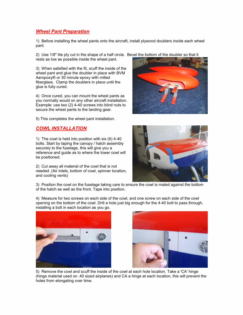
Wheel Pant Preparation 1) Before installing the wheel pants onto the aircraft, install plywood doublers inside each wheel pant. 2) Use 1/8" lite ply cut in the shape of a half circle. Bevel the bottom of the doubler so that it rests as low as possible inside the wheel pant. 3) When satisfied with the fit, scuff the inside of the wheel pant and glue the doubler in place with BVM Aeropoxy® or 30 minute epoxy with milled fiberglass. Clamp the doublers in place until the glue is fully cured. 4) Once cured, you can mount the wheel pants as you normally would on any other aircraft installation. Example: use two (2) 4-40 screws into blind nuts to secure the wheel pants to the landing gear. 5) This completes the wheel pant installation.
COWL INSTALLATION 1) The cowl is held into position with six (6) 4-40 bolts. Start by taping the canopy / hatch assembly securely to the fuselage, this will give you a reference and guide as to where the lower cowl will be positioned. 2) Cut away all material of the cowl that is not needed. (Air inlets, bottom of cowl, spinner location, and cooling vents) 3) Position the cowl on the fuselage taking care to ensure the cowl is mated against the bottom of the hatch as well as the front. Tape into position. 4) Measure for two screws on each side of the cowl, and one screw on each side of the cowl opening on the bottom of the cowl. Drill a hole just big enough for the 4-40 bolt to pass through, installing a bolt in each location as you go.
5) Remove the cowl and scuff the inside of the cowl at each hole location. Take a 'CA' hinge (hinge material used on .40 sized airplanes) and CA a hinge at each location, this will prevent the holes from elongating over time.
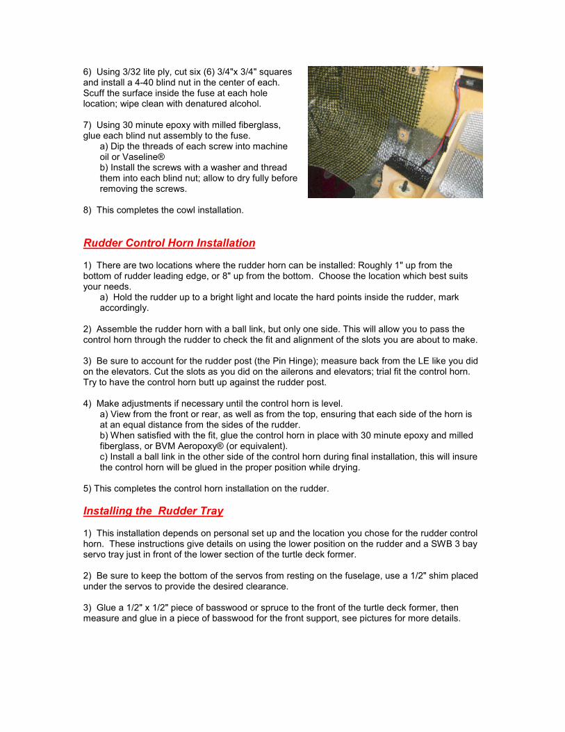
6) Using 3/32 lite ply, cut six (6) 3/4"x 3/4" squares and install a 4-40 blind nut in the center of each. Scuff the surface inside the fuse at each hole location; wipe clean with denatured alcohol. 7) Using 30 minute epoxy with milled fiberglass, glue each blind nut assembly to the fuse.
a) Dip the threads of each screw into machine oil or Vaseline® b) Install the screws with a washer and thread them into each blind nut; allow to dry fully before removing the screws.
8) This completes the cowl installation.
Rudder Control Horn Installation 1) There are two locations where the rudder horn can be installed: Roughly 1" up from the bottom of rudder leading edge, or 8" up from the bottom. Choose the location which best suits your needs.
a) Hold the rudder up to a bright light and locate the hard points inside the rudder, mark accordingly.
2) Assemble the rudder horn with a ball link, but only one side. This will allow you to pass the control horn through the rudder to check the fit and alignment of the slots you are about to make. 3) Be sure to account for the rudder post (the Pin Hinge); measure back from the LE like you did on the elevators. Cut the slots as you did on the ailerons and elevators; trial fit the control horn. Try to have the control horn butt up against the rudder post. 4) Make adjustments if necessary until the control horn is level.
a) View from the front or rear, as well as from the top, ensuring that each side of the horn is at an equal distance from the sides of the rudder. b) When satisfied with the fit, glue the control horn in place with 30 minute epoxy and milled fiberglass, or BVM Aeropoxy® (or equivalent). c) Install a ball link in the other side of the control horn during final installation, this will insure the control horn will be glued in the proper position while drying.
5) This completes the control horn installation on the rudder.
Installing the Rudder Tray 1) This installation depends on personal set up and the location you chose for the rudder control horn. These instructions give details on using the lower position on the rudder and a SWB 3 bay servo tray just in front of the lower section of the turtle deck former. 2) Be sure to keep the bottom of the servos from resting on the fuselage, use a 1/2" shim placed under the servos to provide the desired clearance. 3) Glue a 1/2" x 1/2" piece of basswood or spruce to the front of the turtle deck former, then measure and glue in a piece of basswood for the front support, see pictures for more details.
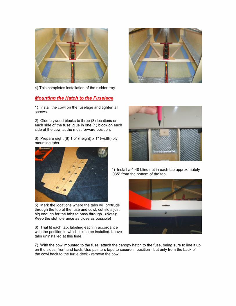
4) This completes installation of the rudder tray.
Mounting the Hatch to the Fuselage 1) Install the cowl on the fuselage and tighten all screws. 2) Glue plywood blocks to three (3) locations on each side of the fuse; glue in one (1) block on each side of the cowl at the most forward position. 3) Prepare eight (8) 1.5" (height) x 1" (width) ply mounting tabs.
4) Install a 4-40 blind nut in each tab approximately .035" from the bottom of the tab.
5) Mark the locations where the tabs will protrude through the top of the fuse and cowl; cut slots just big enough for the tabs to pass through. (Note): Keep the slot tolerance as close as possible! 6) Trial fit each tab, labeling each in accordance with the position in which it is to be installed. Leave tabs uninstalled at this time. 7) With the cowl mounted to the fuse, attach the canopy hatch to the fuse, being sure to line it up on the sides, front and back. Use painters tape to secure in position - but only from the back of the cowl back to the turtle deck - remove the cowl.
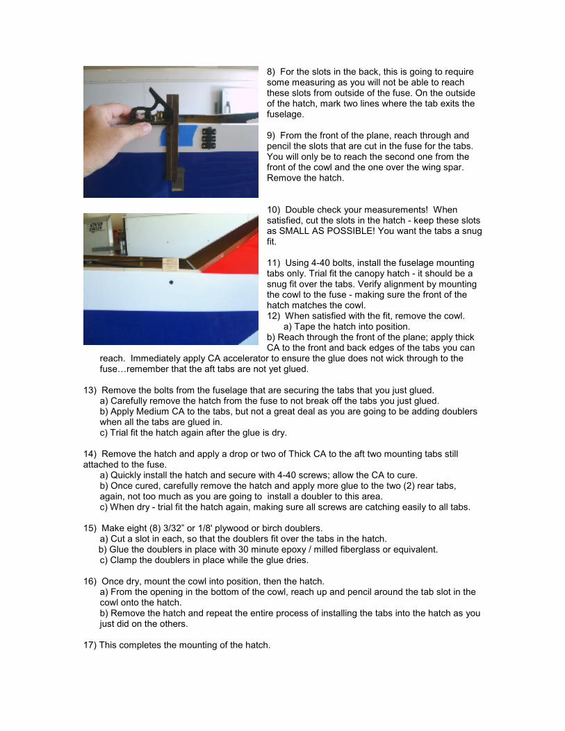
8) For the slots in the back, this is going to require some measuring as you will not be able to reach these slots from outside of the fuse. On the outside of the hatch, mark two lines where the tab exits the fuselage. 9) From the front of the plane, reach through and pencil the slots that are cut in the fuse for the tabs. You will only be to reach the second one from the front of the cowl and the one over the wing spar. Remove the hatch. 10) Double check your measurements! When satisfied, cut the slots in the hatch - keep these slots as SMALL AS POSSIBLE! You want the tabs a snug fit. 11) Using 4-40 bolts, install the fuselage mounting tabs only. Trial fit the canopy hatch - it should be a snug fit over the tabs. Verify alignment by mounting the cowl to the fuse - making sure the front of the hatch matches the cowl. 12) When satisfied with the fit, remove the cowl. a) Tape the hatch into position. b) Reach through the front of the plane; apply thick CA to the front and back edges of the tabs you can
reach. Immediately apply CA accelerator to ensure the glue does not wick through to the fuse…remember that the aft tabs are not yet glued.
13) Remove the bolts from the fuselage that are securing the tabs that you just glued. a) Carefully remove the hatch from the fuse to not break off the tabs you just glued.
b) Apply Medium CA to the tabs, but not a great deal as you are going to be adding doublers when all the tabs are glued in.
c) Trial fit the hatch again after the glue is dry. 14) Remove the hatch and apply a drop or two of Thick CA to the aft two mounting tabs still attached to the fuse. a) Quickly install the hatch and secure with 4-40 screws; allow the CA to cure.
b) Once cured, carefully remove the hatch and apply more glue to the two (2) rear tabs, again, not too much as you are going to install a doubler to this area. c) When dry - trial fit the hatch again, making sure all screws are catching easily to all tabs.
15) Make eight (8) 3/32” or 1/8' plywood or birch doublers. a) Cut a slot in each, so that the doublers fit over the tabs in the hatch. b) Glue the doublers in place with 30 minute epoxy / milled fiberglass or equivalent. c) Clamp the doublers in place while the glue dries. 16) Once dry, mount the cowl into position, then the hatch.
a) From the opening in the bottom of the cowl, reach up and pencil around the tab slot in the cowl onto the hatch. b) Remove the hatch and repeat the entire process of installing the tabs into the hatch as you just did on the others.
17) This completes the mounting of the hatch.
Recommended Servo Arm and Control Horn Set Up Note: Use caution when setting up control throws on the flight control surfaces: You may be required to enlarge the servo arm slots to obtain extreme control throws. Use a Dremel® tool, a round file, or sandpaper to extend the slots. 1) Ailerons - 1.5" servo arms, control rod at the outer most position - obtain at least 27 degrees throw up and down for first flight. 2) Elevators - 1.5" servo arms. Either the 1" or 1.5" hole can be used. Be sure to obtain the best mechanical advantage as possible! See pictures for reference. Obtain at least 12 degree throw up and down for first flight. 3) Rudder - 4" offset bell crank, use the supplied control horn for the rudder. Obtain maximum throw possible. Achieve at least 1.5" throw each direction for first flight. This measurement is obtained by using the LE center of vertical fin to the LE center of the Rudder counterbalance when the rudder is deflected.
Mixes for the Kantan S 1) Elevator to Rudder - at roughly 3/4 throttle, 1 to 2 percent to results in straight hands off knife edge flight. 2) Aileron to Rudder - at roughly 3/4 throttle, 1 to 2 percent to results in straight hands off knife edge flight. 3) Elevator to Throttle - Vertical downline mix (power at idle) - approx 2 to 4 percent down elevator at idle to obtain straight hands off downline. 4) Aileron Differential - Check to see if needed by pulling into 45 deg up line at full power and roll right 3 consecutive rolls. Repeat test rolling to the left. A good starting point is 7 percent more throw going down than up.