Embed Size (px)
Citation preview
3G Long-Term Evolution (LTE) andSystem Architecture Evolution (SAE)
BackgroundSystem ArchitectureRadio InterfaceRadio Resource ManagementLTE-Advanced
Cellular Communication Systems 2Andreas Mitschele-Thiel, Jens Mueckenheim Nov. 2017
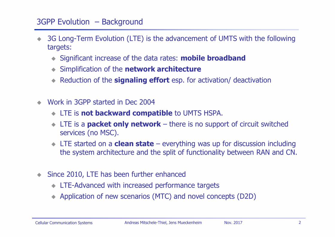
3GPP Evolution – Background
3G Long-Term Evolution (LTE) is the advancement of UMTS with the followingtargets:
Significant increase of the data rates: mobile broadbandSimplification of the network architectureReduction of the signaling effort esp. for activation/ deactivation
Work in 3GPP started in Dec 2004LTE is not backward compatible to UMTS HSPA.LTE is a packet only network – there is no support of circuit switchedservices (no MSC).LTE started on a clean state – everything was up for discussion includingthe system architecture and the split of functionality between RAN and CN.
Since 2010, LTE has been further enhancedLTE-Advanced with increased performance targetsApplication of new scenarios (MTC) and novel concepts (D2D)
Cellular Communication Systems 3Andreas Mitschele-Thiel, Jens Mueckenheim Nov. 2017
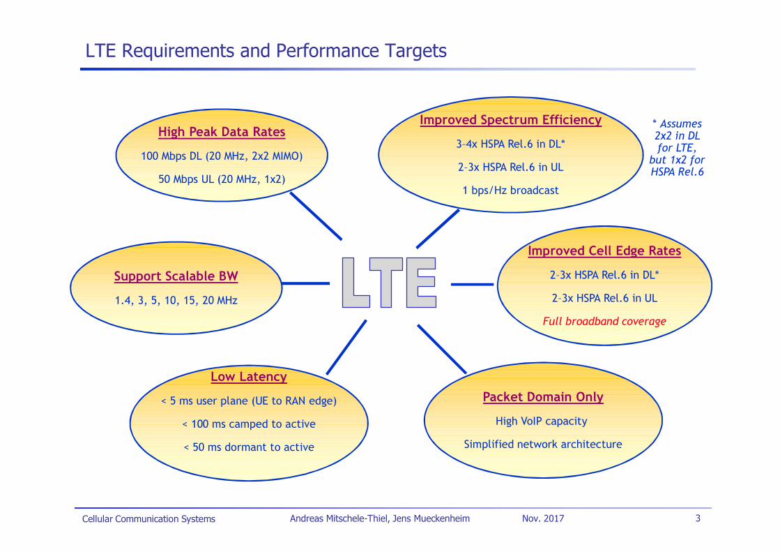
LTE Requirements and Performance Targets
High Peak Data Rates
100 Mbps DL (20 MHz, 2x2 MIMO)
50 Mbps UL (20 MHz, 1x2)
Improved Spectrum Efficiency
3–4x HSPA Rel.6 in DL*
2–3x HSPA Rel.6 in UL
1 bps/Hz broadcast
Improved Cell Edge Rates
2–3x HSPA Rel.6 in DL*
2–3x HSPA Rel.6 in UL
Full broadband coverage
Support Scalable BW
1.4, 3, 5, 10, 15, 20 MHz
Low Latency
< 5 ms user plane (UE to RAN edge)
< 100 ms camped to active
< 50 ms dormant to active
Packet Domain Only
High VoIP capacity
Simplified network architecture
* Assumes2x2 in DLfor LTE,
but 1x2 forHSPA Rel.6
Cellular Communication Systems 4Andreas Mitschele-Thiel, Jens Mueckenheim Nov. 2017
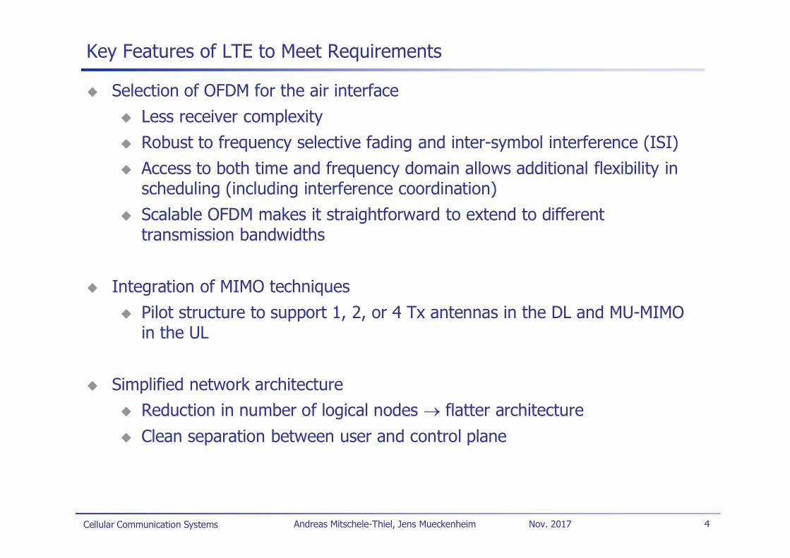
Key Features of LTE to Meet Requirements
Selection of OFDM for the air interfaceLess receiver complexityRobust to frequency selective fading and inter-symbol interference (ISI)Access to both time and frequency domain allows additional flexibility inscheduling (including interference coordination)Scalable OFDM makes it straightforward to extend to differenttransmission bandwidths
Integration of MIMO techniquesPilot structure to support 1, 2, or 4 Tx antennas in the DL and MU-MIMOin the UL
Simplified network architectureReduction in number of logical nodes flatter architectureClean separation between user and control plane
Cellular Communication Systems 5Andreas Mitschele-Thiel, Jens Mueckenheim Nov. 2017
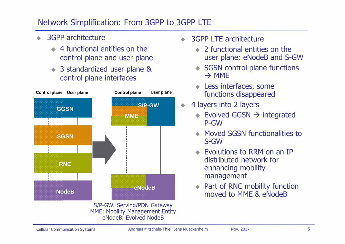
Network Simplification: From 3GPP to 3GPP LTE
3GPP architecture4 functional entities on thecontrol plane and user plane3 standardized user plane &control plane interfaces
3GPP LTE architecture2 functional entities on theuser plane: eNodeB and S-GWSGSN control plane functions
MMELess interfaces, somefunctions disappeared
4 layers into 2 layersEvolved GGSN integratedP-GWMoved SGSN functionalities toS-GWEvolutions to RRM on an IPdistributed network forenhancing mobilitymanagementPart of RNC mobility functionmoved to MME & eNodeB
GGSN
SGSN
RNC
NodeB
ASGW
eNodeB
MMFGGSN
SGSN
RNC
NodeB
Control plane User plane
ASGW
eNodeB
MMF
S/P-GW
eNodeB
MME
Control plane User plane
S/P-GW: Serving/PDN GatewayMME: Mobility Management Entity
eNodeB: Evolved NodeB
Cellular Communication Systems 6Andreas Mitschele-Thiel, Jens Mueckenheim Nov. 2017
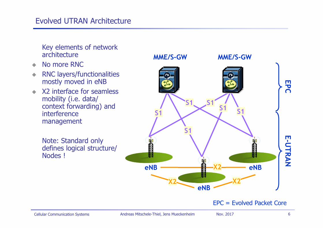
Evolved UTRAN Architecture
eNB
eNB
eNB
MME/S-GW MME/S-GW
X2
EPCE-U
TRAN
S1
S1
S1S1
S1S1
X2
X2
EPC = Evolved Packet Core
Key elements of networkarchitectureNo more RNCRNC layers/functionalitiesmostly moved in eNBX2 interface for seamlessmobility (i.e. data/context forwarding) andinterferencemanagement
Note: Standard onlydefines logical structure/Nodes !
Cellular Communication Systems 7Andreas Mitschele-Thiel, Jens Mueckenheim Nov. 2017
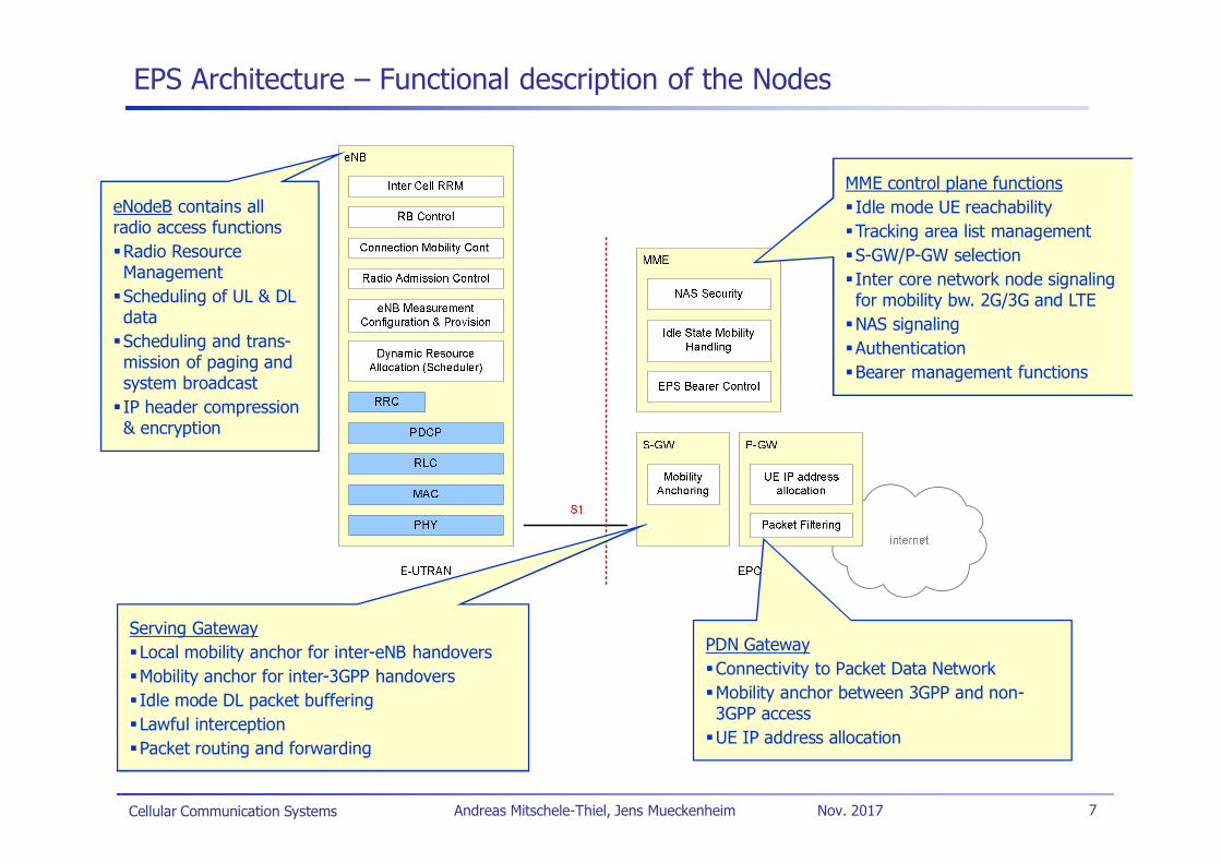
EPS Architecture – Functional description of the Nodes
eNodeB contains allradio access functionsRadio ResourceManagementScheduling of UL & DLdataScheduling and trans-mission of paging andsystem broadcastIP header compression& encryption
Serving GatewayLocal mobility anchor for inter-eNB handoversMobility anchor for inter-3GPP handoversIdle mode DL packet bufferingLawful interceptionPacket routing and forwarding
PDN GatewayConnectivity to Packet Data NetworkMobility anchor between 3GPP and non-3GPP accessUE IP address allocation
MME control plane functionsIdle mode UE reachabilityTracking area list managementS-GW/P-GW selectionInter core network node signalingfor mobility bw. 2G/3G and LTENAS signalingAuthenticationBearer management functions
Cellular Communication Systems 8Andreas Mitschele-Thiel, Jens Mueckenheim Nov. 2017
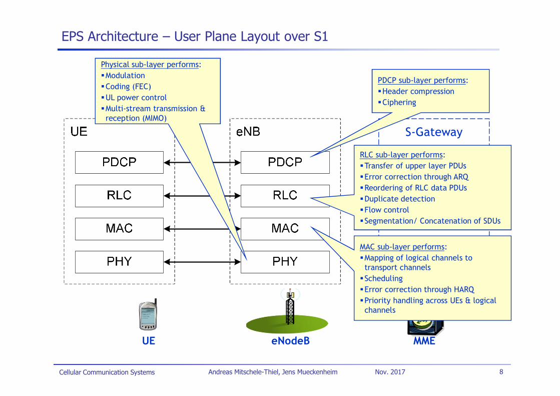
EPS Architecture – User Plane Layout over S1
UE eNodeB MME
S-Gateway
RLC sub-layer performs:Transfer of upper layer PDUsError correction through ARQReordering of RLC data PDUsDuplicate detectionFlow controlSegmentation/ Concatenation of SDUs
PDCP sub-layer performs:Header compressionCiphering
MAC sub-layer performs:Mapping of logical channels totransport channelsSchedulingError correction through HARQPriority handling across UEs & logicalchannels
Physical sub-layer performs:ModulationCoding (FEC)UL power controlMulti-stream transmission &reception (MIMO)
Cellular Communication Systems 9Andreas Mitschele-Thiel, Jens Mueckenheim Nov. 2017
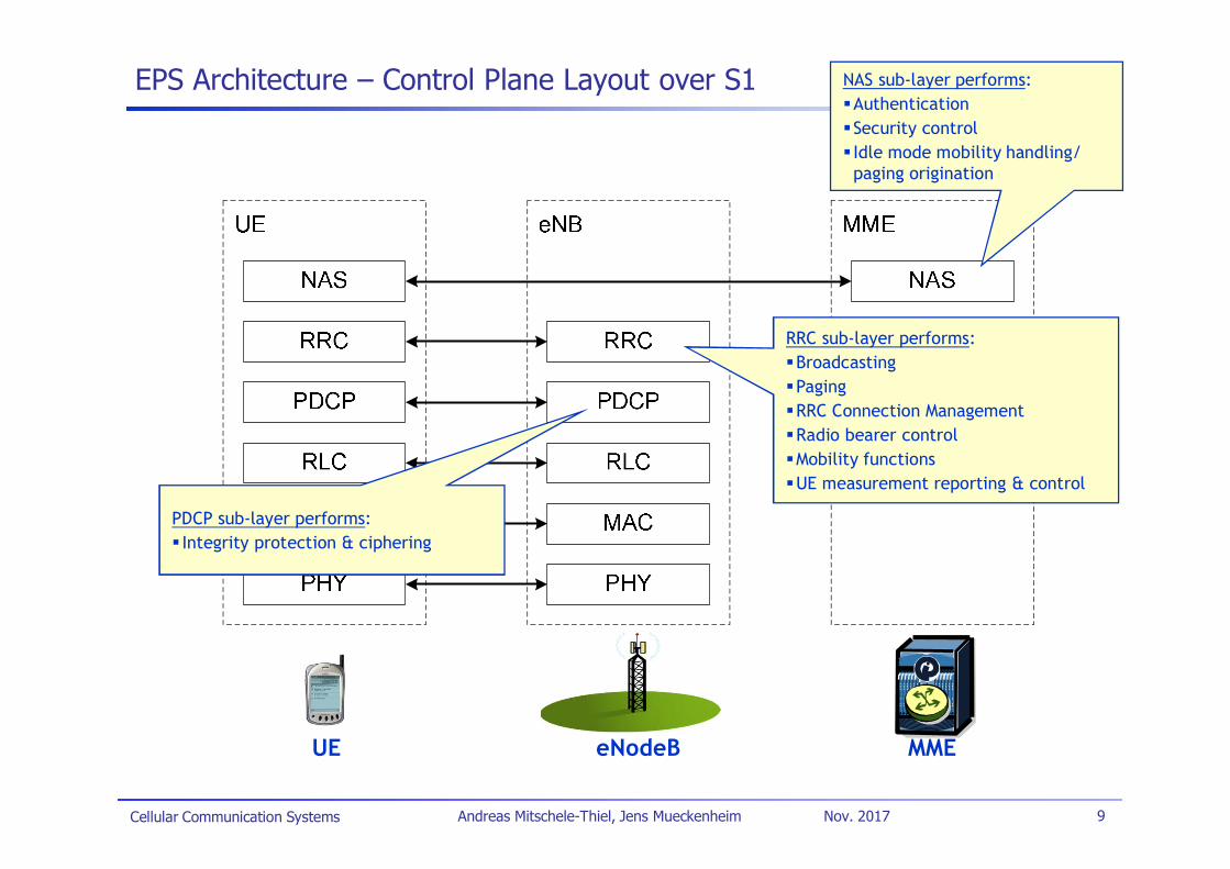
EPS Architecture – Control Plane Layout over S1
UE eNodeB MME
RRC sub-layer performs:BroadcastingPagingRRC Connection ManagementRadio bearer controlMobility functionsUE measurement reporting & control
PDCP sub-layer performs:Integrity protection & ciphering
NAS sub-layer performs:AuthenticationSecurity controlIdle mode mobility handling/paging origination
Cellular Communication Systems 10Andreas Mitschele-Thiel, Jens Mueckenheim Nov. 2017
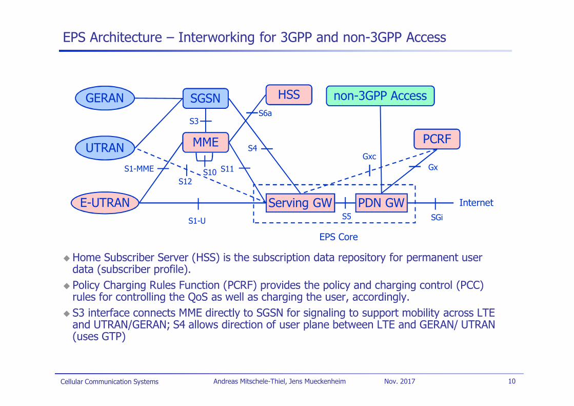
EPS Architecture – Interworking for 3GPP and non-3GPP Access
Home Subscriber Server (HSS) is the subscription data repository for permanent userdata (subscriber profile).Policy Charging Rules Function (PCRF) provides the policy and charging control (PCC)rules for controlling the QoS as well as charging the user, accordingly.S3 interface connects MME directly to SGSN for signaling to support mobility across LTEand UTRAN/GERAN; S4 allows direction of user plane between LTE and GERAN/ UTRAN(uses GTP)
GERAN
UTRAN
E-UTRAN
SGSN
MME
non-3GPP Access
Serving GW PDN GWS1-U
S1-MME S11
S3
S4
S5
Internet
EPS Core
S12
SGi
HSSS6a
S10
PCRF
GxGxc
Cellular Communication Systems 11Andreas Mitschele-Thiel, Jens Mueckenheim Nov. 2017
LTE Key Radio Features (Release 8)
Multiple access schemeDL: OFDMA with CPUL: Single Carrier FDMA (SC-FDMA) with CP
Adaptive modulation and codingDL modulations: QPSK, 16QAM, and 64QAMUL modulations: QPSK, 16QAM, and 64QAM (optional for UE)Rel.6 Turbo code: Coding rate of 1/3, two 8-state constituent encoders,and a contention-free internal interleaver.
ARQ within RLC sublayer and Hybrid ARQ within MAC sublayer.Advanced MIMO spatial multiplexing techniques
(2 or 4)x(2 or 4) downlink and 1x(2 or 4) uplink supported.Multi-layer transmission with up to four streams.Multi-user MIMO also supported.
Implicit support for interference coordinationSupport for both FDD and TDD
Cellular Communication Systems 12Andreas Mitschele-Thiel, Jens Mueckenheim Nov. 2017
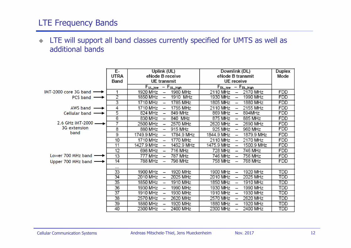
LTE Frequency Bands
LTE will support all band classes currently specified for UMTS as well asadditional bands
Cellular Communication Systems 13Andreas Mitschele-Thiel, Jens Mueckenheim Nov. 2017
OFDM Basics – Overlapping Orthogonal
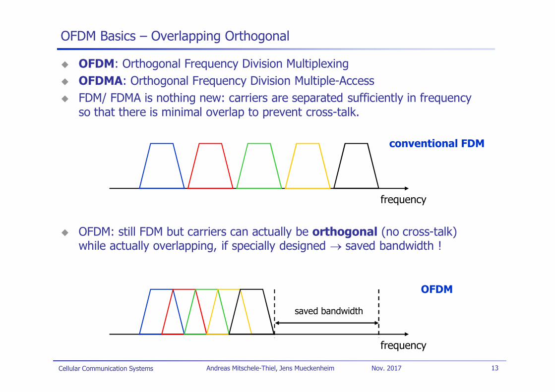
OFDM: Orthogonal Frequency Division MultiplexingOFDMA: Orthogonal Frequency Division Multiple-AccessFDM/ FDMA is nothing new: carriers are separated sufficiently in frequencyso that there is minimal overlap to prevent cross-talk.
OFDM: still FDM but carriers can actually be orthogonal (no cross-talk)while actually overlapping, if specially designed saved bandwidth !
conventional FDM
frequency
OFDM
frequency
saved bandwidth
Cellular Communication Systems 14Andreas Mitschele-Thiel, Jens Mueckenheim Nov. 2017
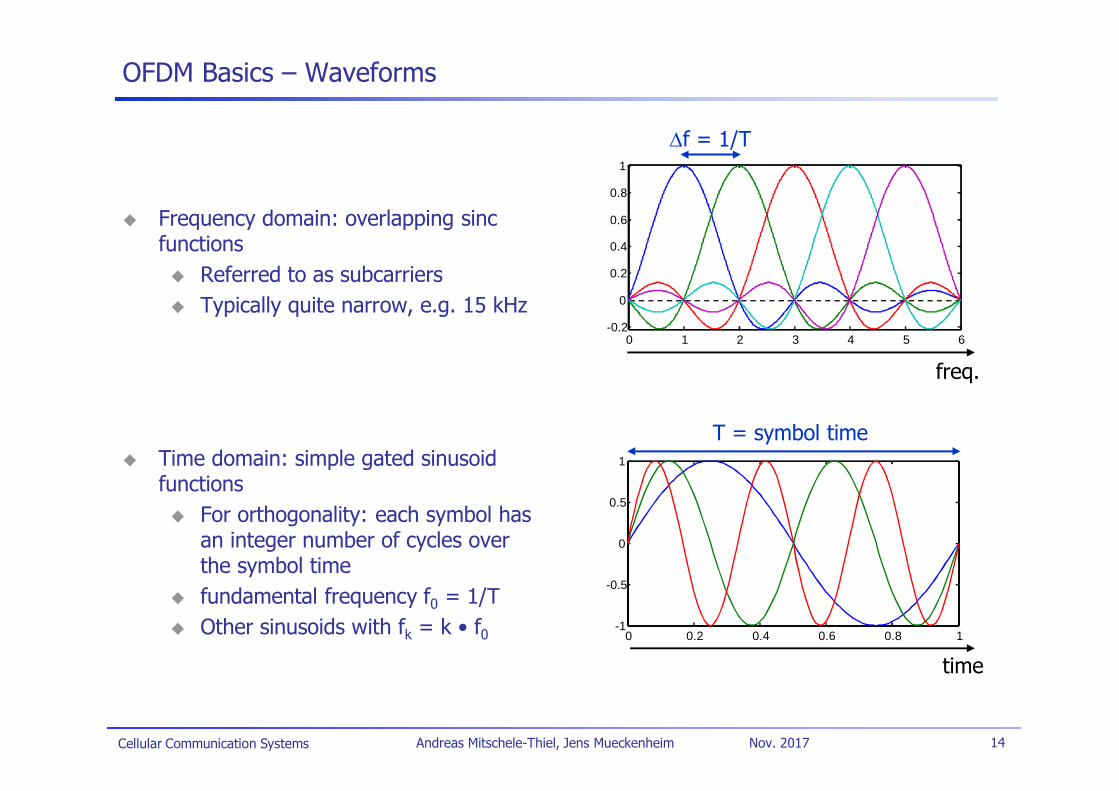
OFDM Basics – Waveforms
Frequency domain: overlapping sincfunctions
Referred to as subcarriersTypically quite narrow, e.g. 15 kHz
Time domain: simple gated sinusoidfunctions
For orthogonality: each symbol hasan integer number of cycles overthe symbol timefundamental frequency f0 = 1/TOther sinusoids with fk = k • f0
f = 1/T
freq.
time
T = symbol time
0 1 2 3 4 5 6-0.2
0
0.2
0.4
0.6
0.8
1
0 0.2 0.4 0.6 0.8 1-1
-0.5
0
0.5
1
Cellular Communication Systems 15Andreas Mitschele-Thiel, Jens Mueckenheim Nov. 2017
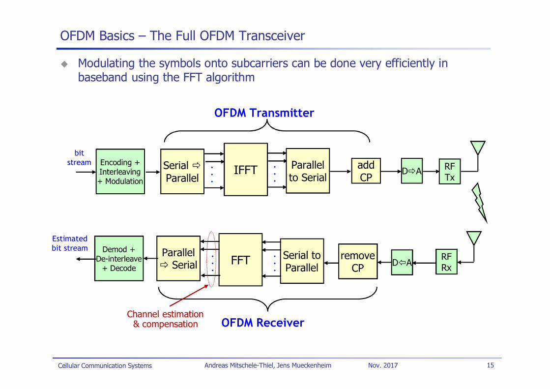
OFDM Basics – The Full OFDM Transceiver
Modulating the symbols onto subcarriers can be done very efficiently inbaseband using the FFT algorithm
SerialParallel
..
. IFFT
bitstream .
..
Parallelto Serial
D A
D ASerial toParallel
..
.FFT
..
.
OFDM Transmitter
OFDM Receiver
ParallelSerial
addCP
RFTx
RFRx
removeCP
Encoding +Interleaving+ Modulation
Demod +De-interleave
+ Decode
Estimatedbit stream
Channel estimation& compensation
Cellular Communication Systems 16Andreas Mitschele-Thiel, Jens Mueckenheim Nov. 2017
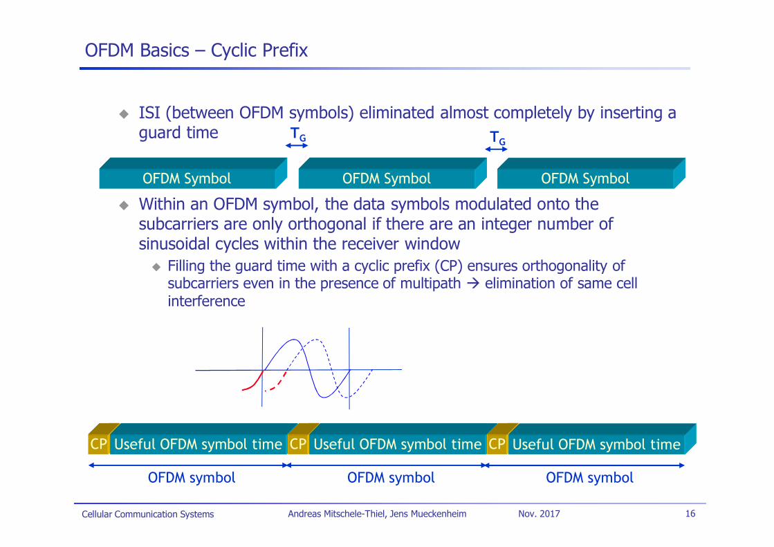
OFDM Basics – Cyclic Prefix
ISI (between OFDM symbols) eliminated almost completely by inserting aguard time
Within an OFDM symbol, the data symbols modulated onto thesubcarriers are only orthogonal if there are an integer number ofsinusoidal cycles within the receiver window
Filling the guard time with a cyclic prefix (CP) ensures orthogonality ofsubcarriers even in the presence of multipath elimination of same cellinterference
CP Useful OFDM symbol time
OFDM symbol
CP Useful OFDM symbol time
OFDM symbol
CP Useful OFDM symbol time
OFDM symbol
OFDM Symbol OFDM Symbol OFDM Symbol
TG TG
Cellular Communication Systems 17Andreas Mitschele-Thiel, Jens Mueckenheim Nov. 2017
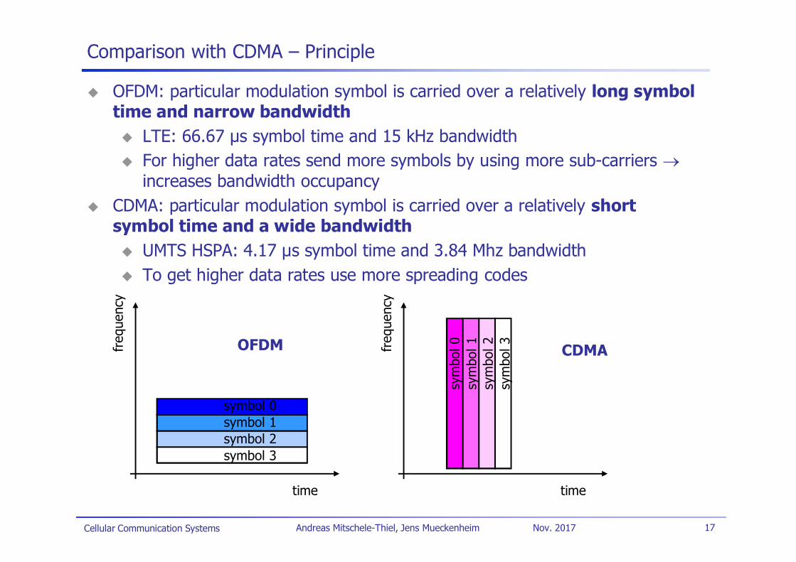
Comparison with CDMA – Principle
OFDM: particular modulation symbol is carried over a relatively long symboltime and narrow bandwidth
LTE: 66.67 µs symbol time and 15 kHz bandwidthFor higher data rates send more symbols by using more sub-carriersincreases bandwidth occupancy
CDMA: particular modulation symbol is carried over a relatively shortsymbol time and a wide bandwidth
UMTS HSPA: 4.17 µs symbol time and 3.84 Mhz bandwidthTo get higher data rates use more spreading codes
time
freq
uenc
y
symbol 0symbol 1symbol 2symbol 3
time
freq
uenc
y
sym
bol0
sym
bol1
sym
bol2
sym
bol3OFDM CDMA
Cellular Communication Systems 18Andreas Mitschele-Thiel, Jens Mueckenheim Nov. 2017
Comparison with CDMA – Time Domain Perspective
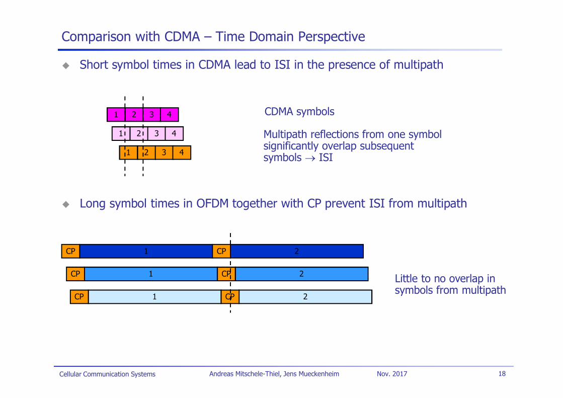
Short symbol times in CDMA lead to ISI in the presence of multipath
Long symbol times in OFDM together with CP prevent ISI from multipath
1 2 3 4
1 2 3 4
1 2 3 4
CDMA symbols
Multipath reflections from one symbolsignificantly overlap subsequentsymbols ISI
1 2CPCP
1 2CPCP
1 2CPCP
Little to no overlap insymbols from multipath
Cellular Communication Systems 19Andreas Mitschele-Thiel, Jens Mueckenheim Nov. 2017
Comparison with CDMA – Frequency Domain Perspective
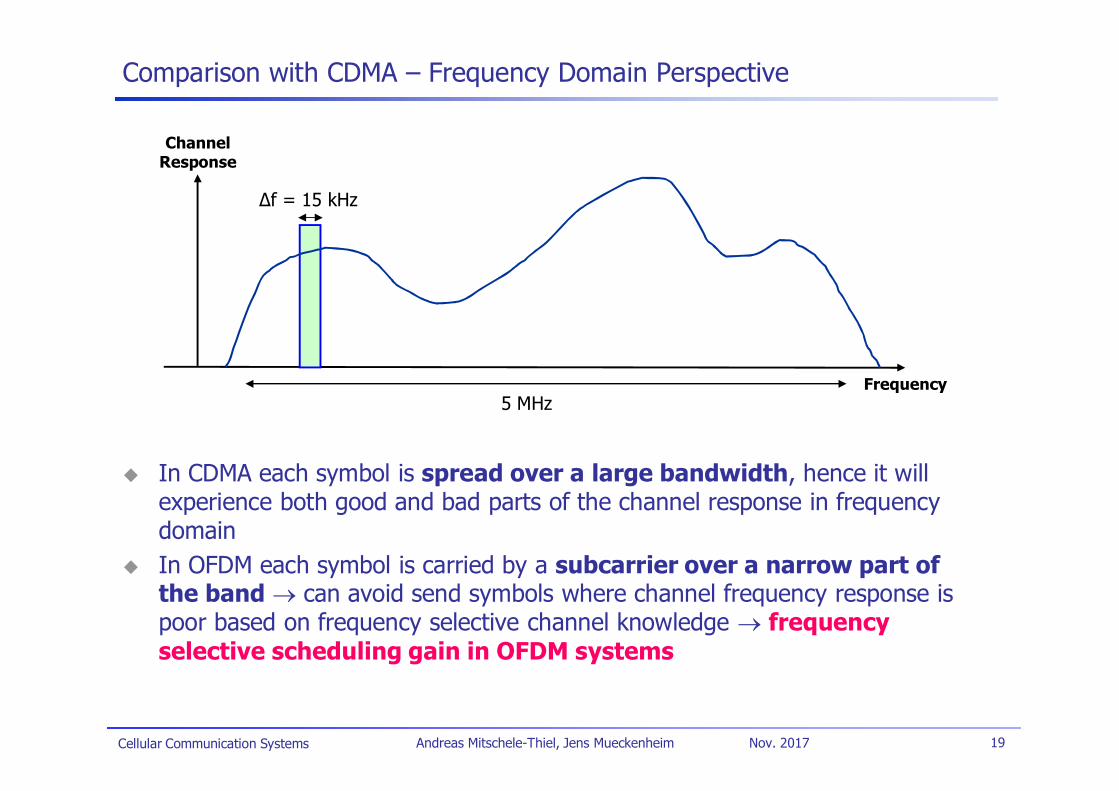
In CDMA each symbol is spread over a large bandwidth, hence it willexperience both good and bad parts of the channel response in frequencydomainIn OFDM each symbol is carried by a subcarrier over a narrow part ofthe band can avoid send symbols where channel frequency response ispoor based on frequency selective channel knowledge frequencyselective scheduling gain in OFDM systems
Frequency
ChannelResponse
f = 15 kHz
5 MHz
Cellular Communication Systems 20Andreas Mitschele-Thiel, Jens Mueckenheim Nov. 2017
OFDM Basics – Choosing the Symbol Time for LTE
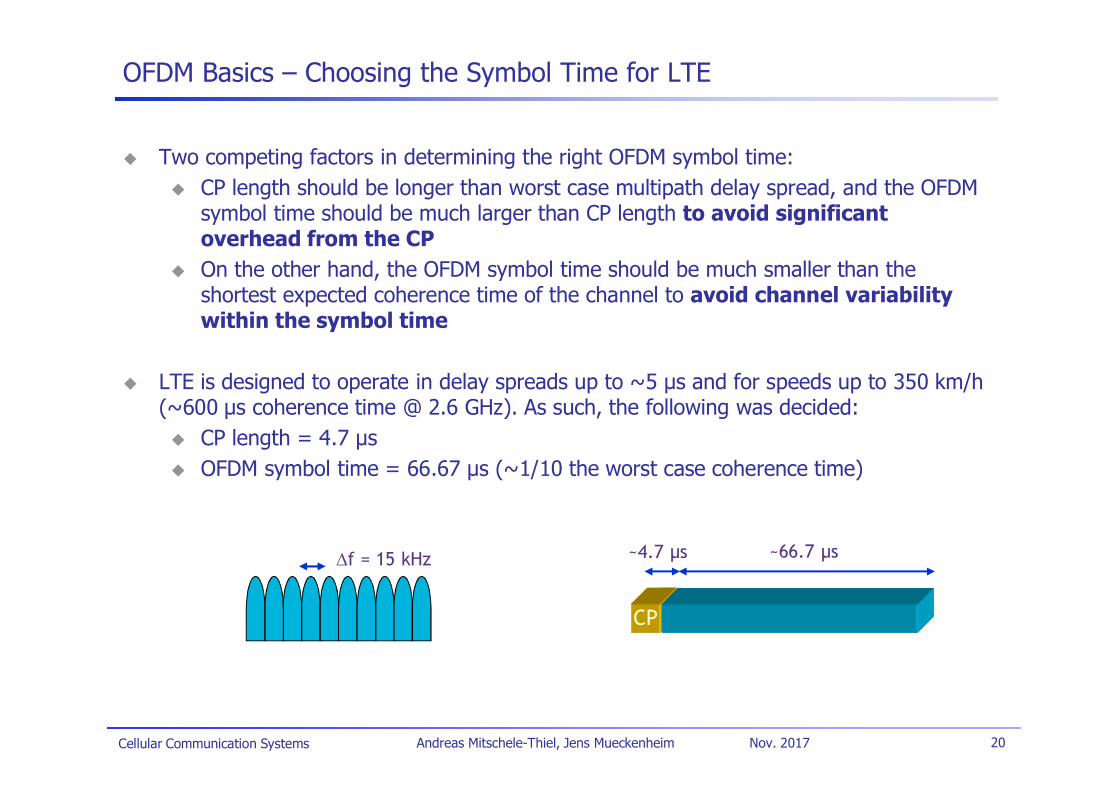
Two competing factors in determining the right OFDM symbol time:CP length should be longer than worst case multipath delay spread, and the OFDMsymbol time should be much larger than CP length to avoid significantoverhead from the CPOn the other hand, the OFDM symbol time should be much smaller than theshortest expected coherence time of the channel to avoid channel variabilitywithin the symbol time
LTE is designed to operate in delay spreads up to ~5 s and for speeds up to 350 km/h(~600 µs coherence time @ 2.6 GHz). As such, the following was decided:
CP length = 4.7 sOFDM symbol time = 66.67 s (~1/10 the worst case coherence time)
f = 15 kHz
CP
~4.7 µs ~66.7 µs
Cellular Communication Systems 21Andreas Mitschele-Thiel, Jens Mueckenheim Nov. 2017
Scalable OFDM for Different Operating Bandwidths
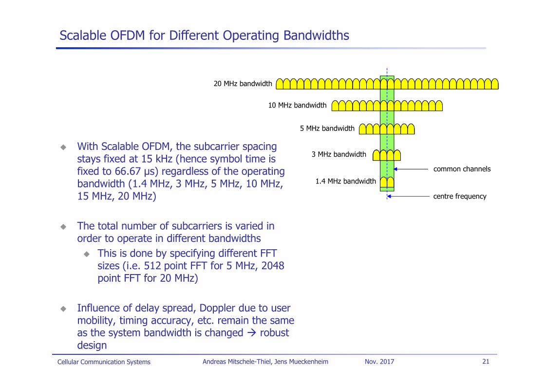
With Scalable OFDM, the subcarrier spacingstays fixed at 15 kHz (hence symbol time isfixed to 66.67 µs) regardless of the operatingbandwidth (1.4 MHz, 3 MHz, 5 MHz, 10 MHz,15 MHz, 20 MHz)
The total number of subcarriers is varied inorder to operate in different bandwidths
This is done by specifying different FFTsizes (i.e. 512 point FFT for 5 MHz, 2048point FFT for 20 MHz)
Influence of delay spread, Doppler due to usermobility, timing accuracy, etc. remain the sameas the system bandwidth is changed robustdesign
common channels
10 MHz bandwidth
20 MHz bandwidth
5 MHz bandwidth
1.4 MHz bandwidth
3 MHz bandwidth
centre frequency
Cellular Communication Systems 22Andreas Mitschele-Thiel, Jens Mueckenheim Nov. 2017
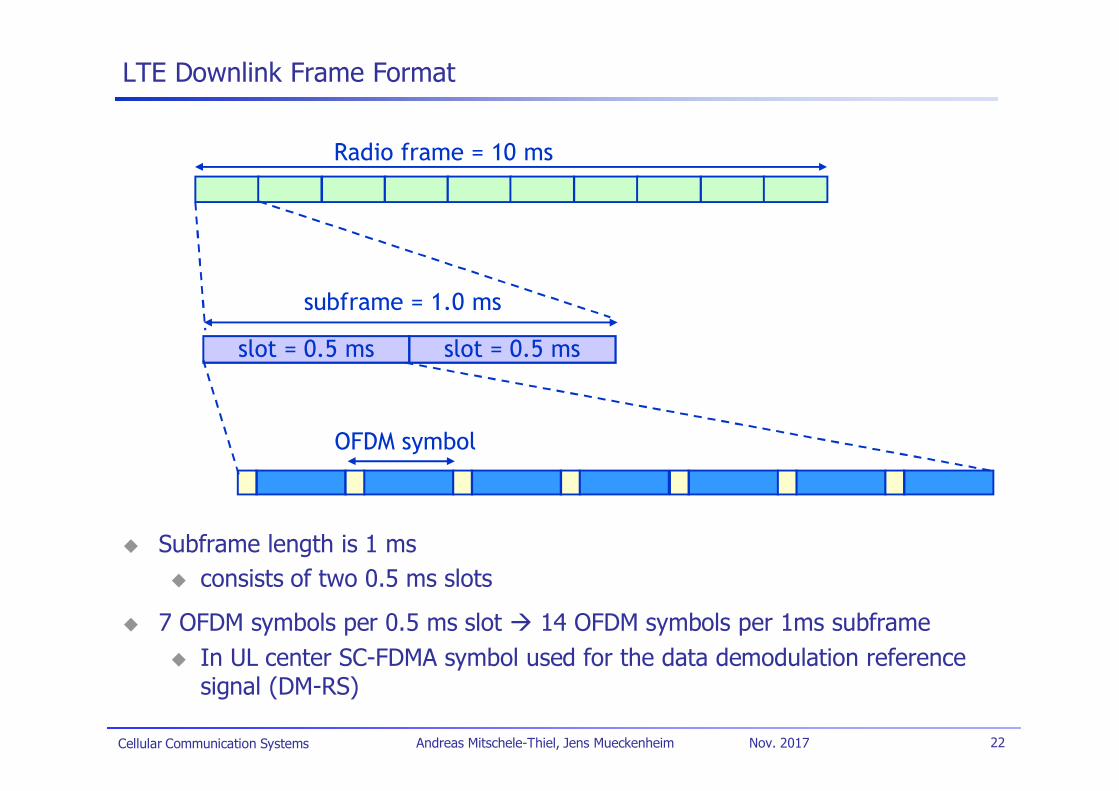
LTE Downlink Frame Format
Subframe length is 1 msconsists of two 0.5 ms slots
7 OFDM symbols per 0.5 ms slot 14 OFDM symbols per 1ms subframeIn UL center SC-FDMA symbol used for the data demodulation referencesignal (DM-RS)
slot = 0.5 ms slot = 0.5 ms
subframe = 1.0 ms
OFDM symbol
Radio frame = 10 ms
Cellular Communication Systems 23Andreas Mitschele-Thiel, Jens Mueckenheim Nov. 2017
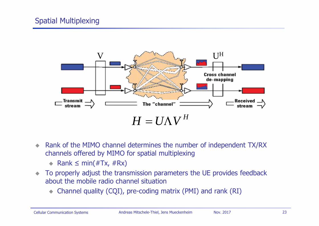
Spatial Multiplexing
Rank of the MIMO channel determines the number of independent TX/RXchannels offered by MIMO for spatial multiplexing
Rank min(#Tx, #Rx)To properly adjust the transmission parameters the UE provides feedbackabout the mobile radio channel situation
Channel quality (CQI), pre-coding matrix (PMI) and rank (RI)
HVUH
UHV
Cellular Communication Systems 24Andreas Mitschele-Thiel, Jens Mueckenheim Nov. 2017
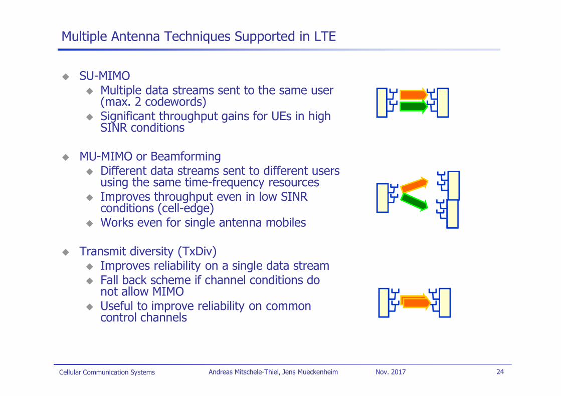
Multiple Antenna Techniques Supported in LTE
SU-MIMOMultiple data streams sent to the same user(max. 2 codewords)Significant throughput gains for UEs in highSINR conditions
MU-MIMO or BeamformingDifferent data streams sent to different usersusing the same time-frequency resourcesImproves throughput even in low SINRconditions (cell-edge)Works even for single antenna mobiles
Transmit diversity (TxDiv)Improves reliability on a single data streamFall back scheme if channel conditions donot allow MIMOUseful to improve reliability on commoncontrol channels
Cellular Communication Systems 25Andreas Mitschele-Thiel, Jens Mueckenheim Nov. 2017
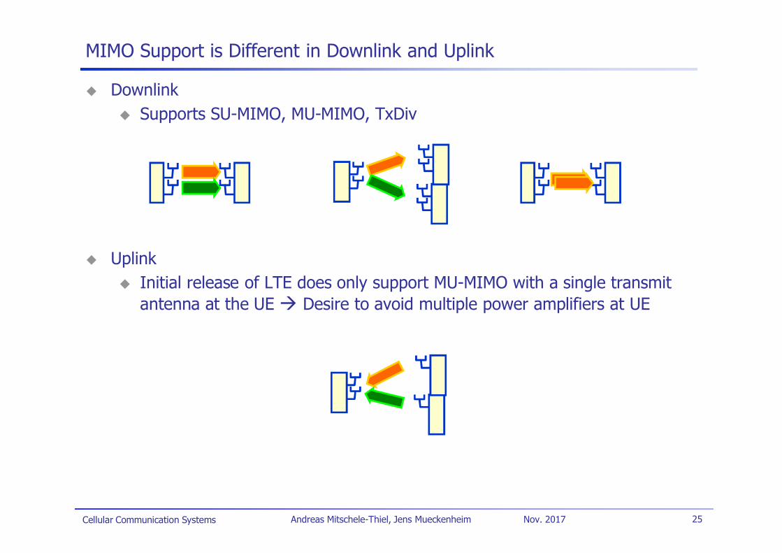
MIMO Support is Different in Downlink and Uplink
DownlinkSupports SU-MIMO, MU-MIMO, TxDiv
UplinkInitial release of LTE does only support MU-MIMO with a single transmitantenna at the UE Desire to avoid multiple power amplifiers at UE
Cellular Communication Systems 26Andreas Mitschele-Thiel, Jens Mueckenheim Nov. 2017
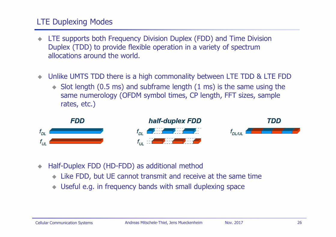
LTE Duplexing Modes
LTE supports both Frequency Division Duplex (FDD) and Time DivisionDuplex (TDD) to provide flexible operation in a variety of spectrumallocations around the world.
Unlike UMTS TDD there is a high commonality between LTE TDD & LTE FDDSlot length (0.5 ms) and subframe length (1 ms) is the same using thesame numerology (OFDM symbol times, CP length, FFT sizes, samplerates, etc.)
Half-Duplex FDD (HD-FDD) as additional methodLike FDD, but UE cannot transmit and receive at the same timeUseful e.g. in frequency bands with small duplexing space

Cellular Communication Systems 27Andreas Mitschele-Thiel, Jens Mueckenheim Nov. 2017
LTE Downlink
The LTE downlink uses scalable OFDMAFixed subcarrier spacing of 15 kHz for unicast
Symbol time fixed at T = 1/15 kHz = 66.67 µs
Different UEs are assigned different sets of subcarriers so that theyremain orthogonal to each other (except MU-MIMO)
Serial toParallel
..
.
IFFTbit
stream ..
.
Parallelto Serial
addCP
Encoding +Interleaving+ Modulation
20 MHz: 2048 pt IFFT10 MHz: 1024 pt IFFT5 MHz: 512 pt IFFT
Cellular Communication Systems 28Andreas Mitschele-Thiel, Jens Mueckenheim Nov. 2017
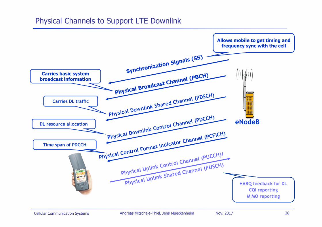
Physical Channels to Support LTE Downlink
eNodeB
Carries DL traffic
DL resource allocation
HARQ feedback for DLCQI reporting
MIMO reporting
Time span of PDCCH
Carries basic systembroadcast information
Allows mobile to get timing andfrequency sync with the cell
Cellular Communication Systems 29Andreas Mitschele-Thiel, Jens Mueckenheim Nov. 2017
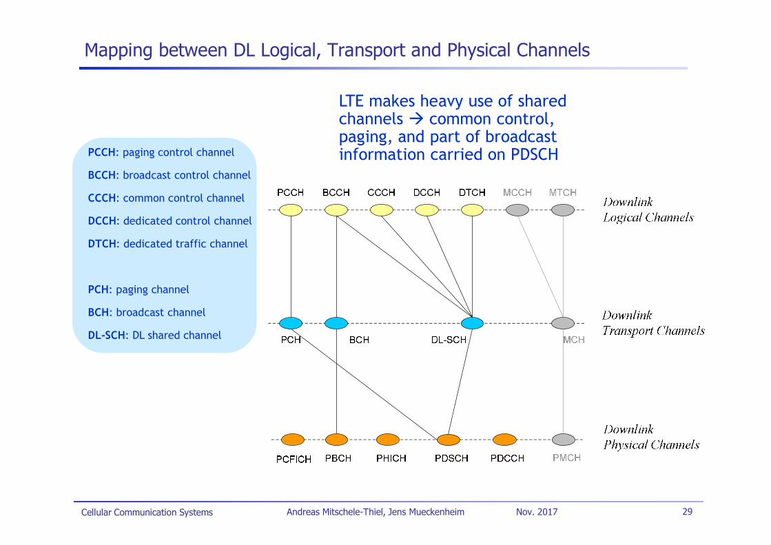
Mapping between DL Logical, Transport and Physical Channels
LTE makes heavy use of sharedchannels common control,paging, and part of broadcastinformation carried on PDSCHPCCH: paging control channel
BCCH: broadcast control channel
CCCH: common control channel
DCCH: dedicated control channel
DTCH: dedicated traffic channel
PCH: paging channel
BCH: broadcast channel
DL-SCH: DL shared channel
Cellular Communication Systems 30Andreas Mitschele-Thiel, Jens Mueckenheim Nov. 2017
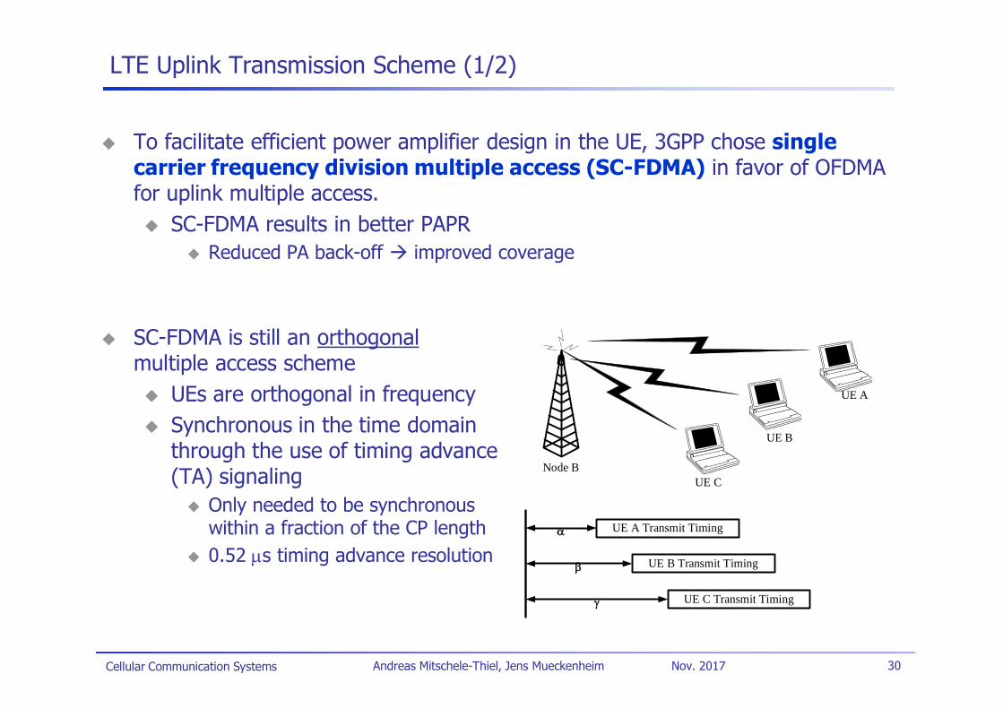
LTE Uplink Transmission Scheme (1/2)
To facilitate efficient power amplifier design in the UE, 3GPP chose singlecarrier frequency division multiple access (SC-FDMA) in favor of OFDMAfor uplink multiple access.
SC-FDMA results in better PAPRReduced PA back-off improved coverage
SC-FDMA is still an orthogonalmultiple access scheme
UEs are orthogonal in frequencySynchronous in the time domainthrough the use of timing advance(TA) signaling
Only needed to be synchronouswithin a fraction of the CP length0.52 s timing advance resolution
Node BUE C
UE B
UE A
UE A Transmit Timing
UE B Transmit Timing
UE C Transmit Timing
Cellular Communication Systems 31Andreas Mitschele-Thiel, Jens Mueckenheim Nov. 2017
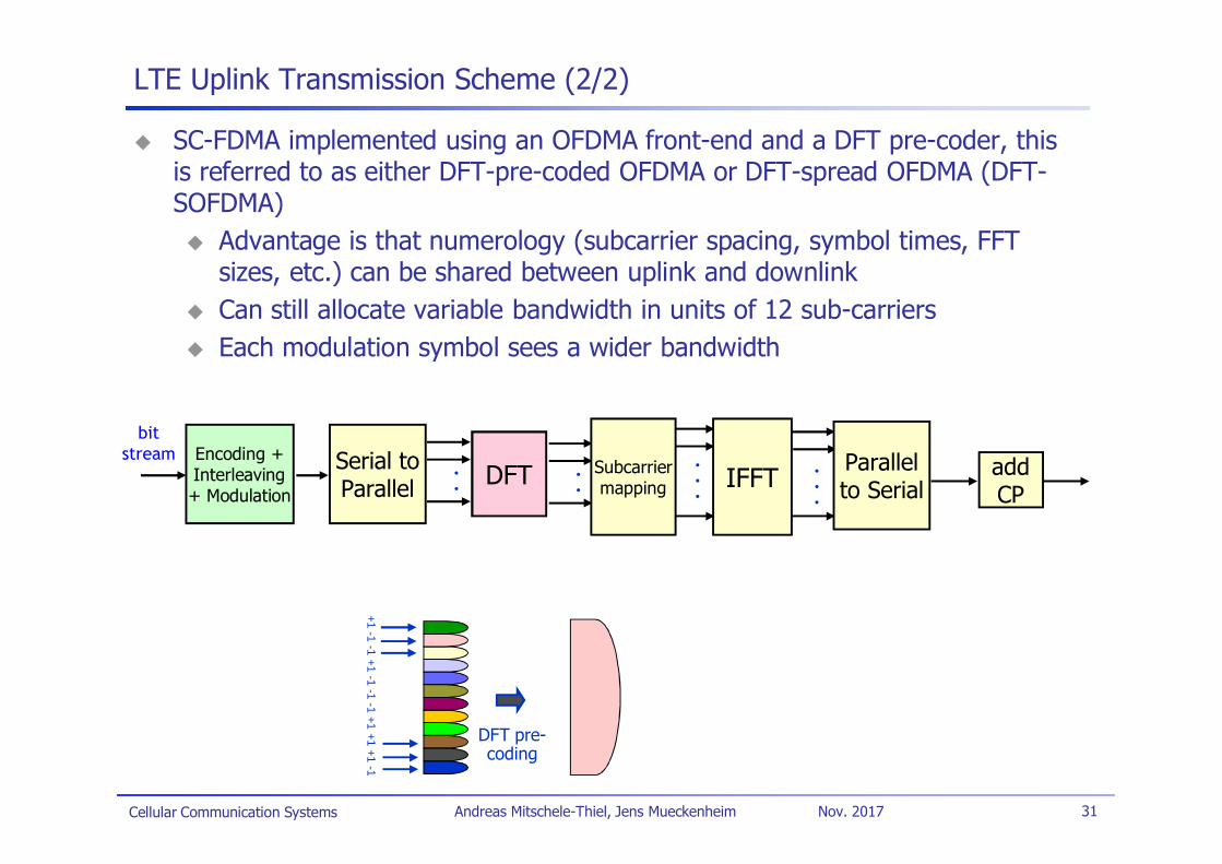
LTE Uplink Transmission Scheme (2/2)
SC-FDMA implemented using an OFDMA front-end and a DFT pre-coder, thisis referred to as either DFT-pre-coded OFDMA or DFT-spread OFDMA (DFT-SOFDMA)
Advantage is that numerology (subcarrier spacing, symbol times, FFTsizes, etc.) can be shared between uplink and downlinkCan still allocate variable bandwidth in units of 12 sub-carriersEach modulation symbol sees a wider bandwidth
+1-1
-1+1
-1-1
-1+1
+1+1
-1
DFT pre-coding
Serial toParallel IFFT
bitstream .
..
Parallelto Serial
addCP
Encoding +Interleaving+ Modulation
.. DFT
..
.
.. Subcarrier
mapping
Cellular Communication Systems 32Andreas Mitschele-Thiel, Jens Mueckenheim Nov. 2017
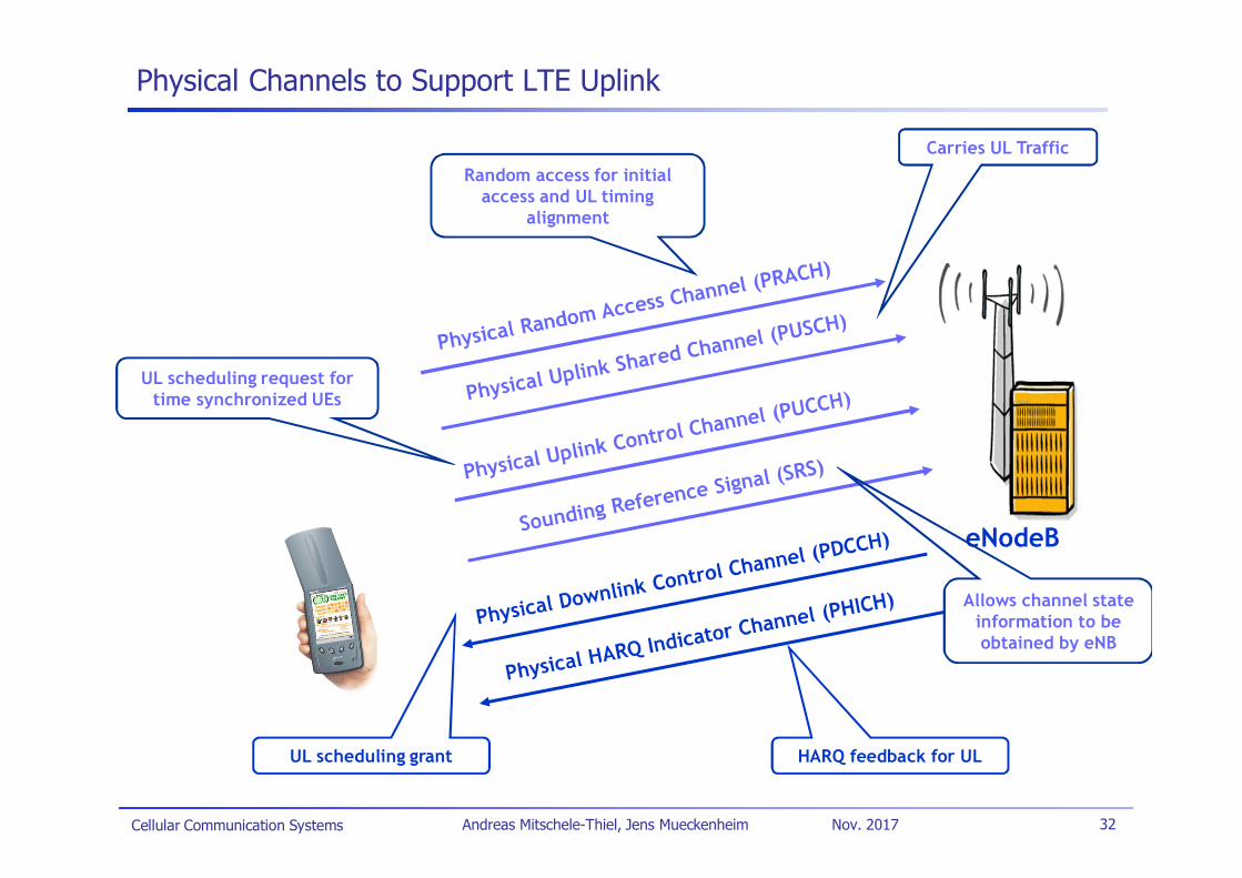
Physical Channels to Support LTE Uplink
eNodeB
Random access for initialaccess and UL timing
alignment
UL scheduling grant
Carries UL Traffic
UL scheduling request fortime synchronized UEs
HARQ feedback for UL
Allows channel stateinformation to beobtained by eNB
Cellular Communication Systems 33Andreas Mitschele-Thiel, Jens Mueckenheim Nov. 2017
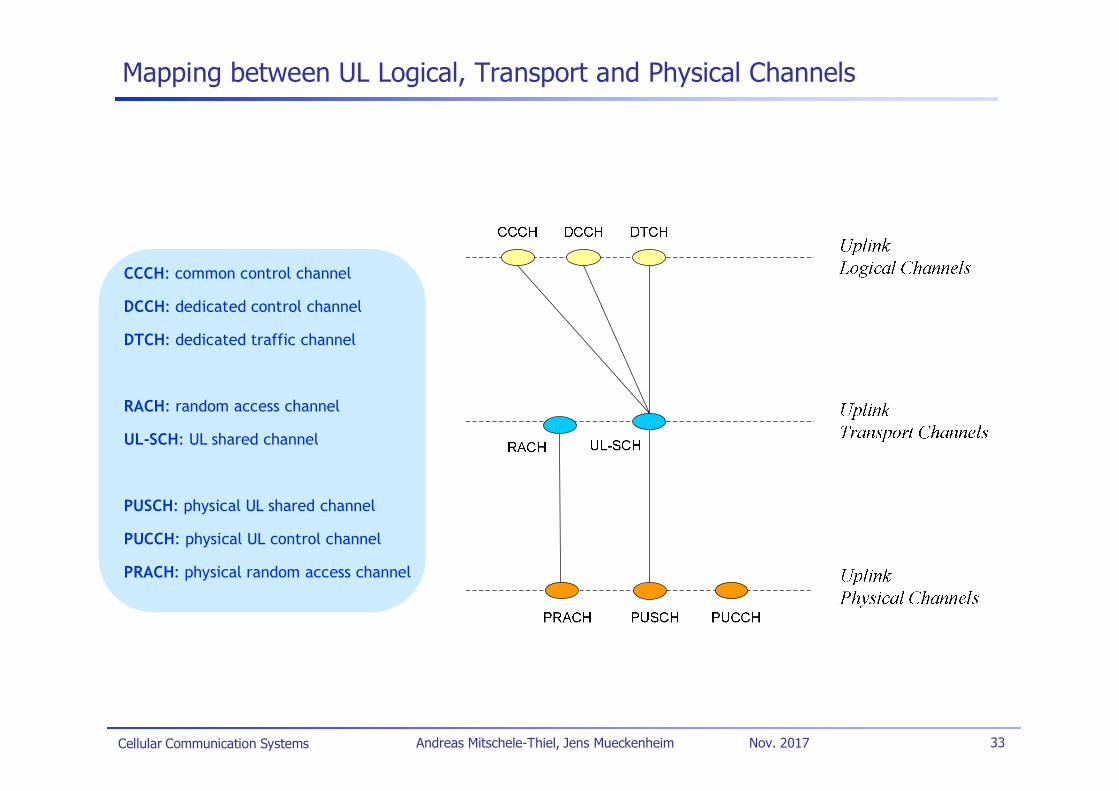
Mapping between UL Logical, Transport and Physical Channels
CCCH: common control channel
DCCH: dedicated control channel
DTCH: dedicated traffic channel
RACH: random access channel
UL-SCH: UL shared channel
PUSCH: physical UL shared channel
PUCCH: physical UL control channel
PRACH: physical random access channel
Cellular Communication Systems 34Andreas Mitschele-Thiel, Jens Mueckenheim Nov. 2017
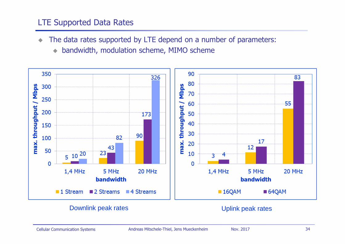
LTE Supported Data Rates
The data rates supported by LTE depend on a number of parameters:bandwidth, modulation scheme, MIMO scheme
Downlink peak rates Uplink peak rates
Cellular Communication Systems 35Andreas Mitschele-Thiel, Jens Mueckenheim Nov. 2017
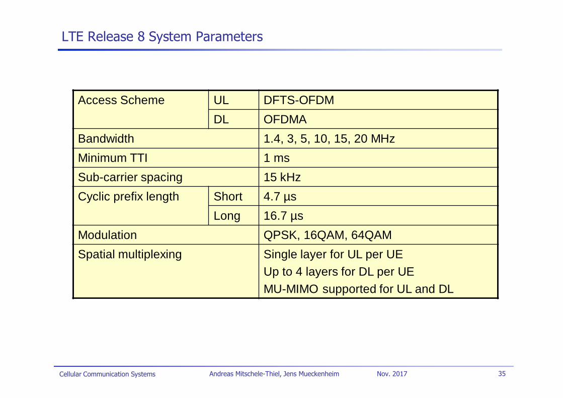
LTE Release 8 System Parameters
Access Scheme UL DFTS-OFDMDL OFDMA
Bandwidth 1.4, 3, 5, 10, 15, 20 MHzMinimum TTI 1 msSub-carrier spacing 15 kHzCyclic prefix length Short 4.7 µs
Long 16.7 µsModulation QPSK, 16QAM, 64QAMSpatial multiplexing Single layer for UL per UE
Up to 4 layers for DL per UEMU-MIMO supported for UL and DL
Cellular Communication Systems 36Andreas Mitschele-Thiel, Jens Mueckenheim Nov. 2017
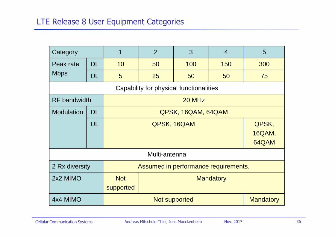
LTE Release 8 User Equipment Categories
Category 1 2 3 4 5
Peak rateMbps
DL 10 50 100 150 300
UL 5 25 50 50 75
Capability for physical functionalities
RF bandwidth 20 MHz
Modulation DL QPSK, 16QAM, 64QAM
UL QPSK, 16QAM QPSK,16QAM,64QAM
Multi-antenna
2 Rx diversity Assumed in performance requirements.
2x2 MIMO Notsupported
Mandatory
4x4 MIMO Not supported Mandatory
Cellular Communication Systems 37Andreas Mitschele-Thiel, Jens Mueckenheim Nov. 2017
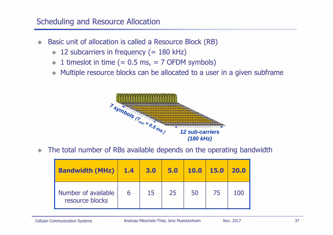
Scheduling and Resource Allocation
Basic unit of allocation is called a Resource Block (RB)12 subcarriers in frequency (= 180 kHz)1 timeslot in time (= 0.5 ms, = 7 OFDM symbols)Multiple resource blocks can be allocated to a user in a given subframe
The total number of RBs available depends on the operating bandwidth
12 sub-carriers(180 kHz)
Bandwidth (MHz) 1.4 3.0 5.0 10.0 15.0 20.0
Number of availableresource blocks
6 15 25 50 75 100
Cellular Communication Systems 38Andreas Mitschele-Thiel, Jens Mueckenheim Nov. 2017
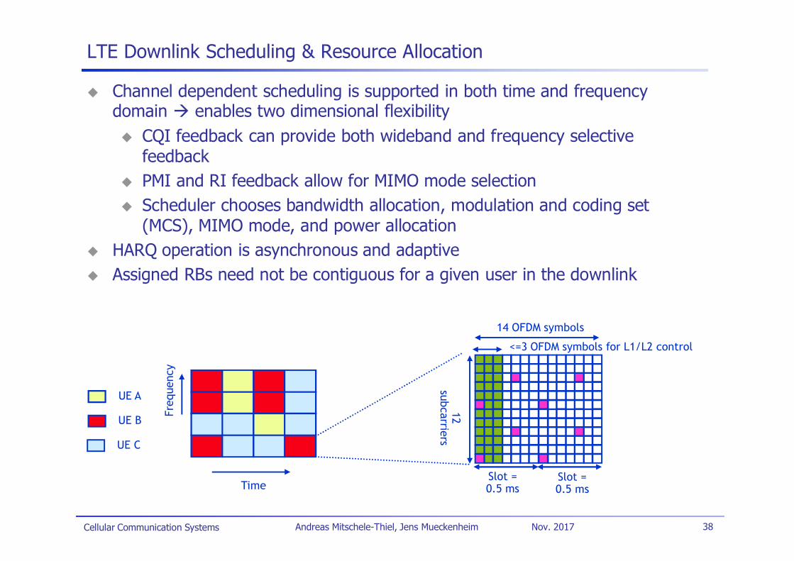
LTE Downlink Scheduling & Resource Allocation
Channel dependent scheduling is supported in both time and frequencydomain enables two dimensional flexibility
CQI feedback can provide both wideband and frequency selectivefeedbackPMI and RI feedback allow for MIMO mode selectionScheduler chooses bandwidth allocation, modulation and coding set(MCS), MIMO mode, and power allocation
HARQ operation is asynchronous and adaptiveAssigned RBs need not be contiguous for a given user in the downlink
14 OFDM symbols12
subcarriers
Slot =0.5 ms
Slot =0.5 ms
UE A
UE B
UE C
Time
Freq
uenc
y
<=3 OFDM symbols for L1/L2 control
Cellular Communication Systems 39Andreas Mitschele-Thiel, Jens Mueckenheim Nov. 2017
LTE Uplink Scheduling & Resource Allocation
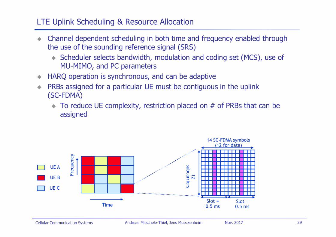
Channel dependent scheduling in both time and frequency enabled throughthe use of the sounding reference signal (SRS)
Scheduler selects bandwidth, modulation and coding set (MCS), use ofMU-MIMO, and PC parameters
HARQ operation is synchronous, and can be adaptivePRBs assigned for a particular UE must be contiguous in the uplink(SC-FDMA)
To reduce UE complexity, restriction placed on # of PRBs that can beassigned
14 SC-FDMA symbols(12 for data)
12subcarriers
Slot =0.5 ms
Slot =0.5 ms
UE A
UE B
UE C
Time
Freq
uenc
y
Cellular Communication Systems 40Andreas Mitschele-Thiel, Jens Mueckenheim Nov. 2017
Uplink Power Control
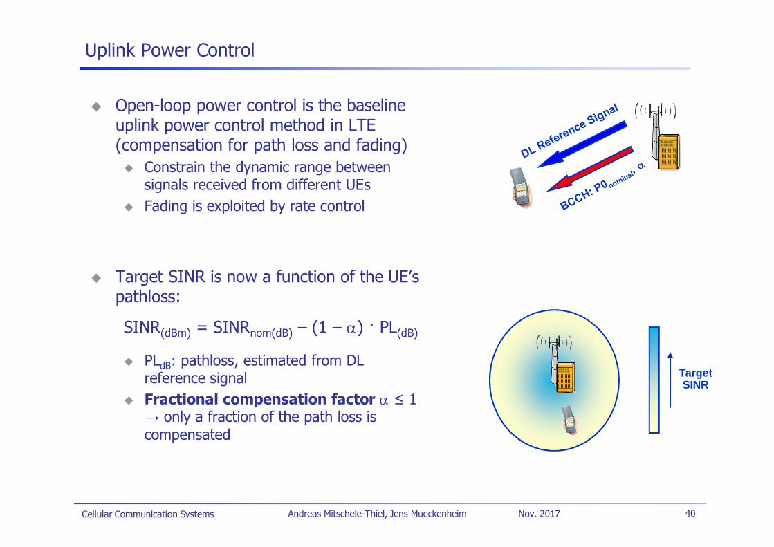
Open-loop power control is the baselineuplink power control method in LTE(compensation for path loss and fading)
Constrain the dynamic range betweensignals received from different UEsFading is exploited by rate control
Target SINR is now a function of the UE’spathloss:
SINR(dBm) = SINRnom(dB) – (1 – ) · PL(dB)
PLdB: pathloss, estimated from DLreference signalFractional compensation factor 1
only a fraction of the path loss iscompensated
TargetSINR
Cellular Communication Systems 41Andreas Mitschele-Thiel, Jens Mueckenheim Nov. 2017
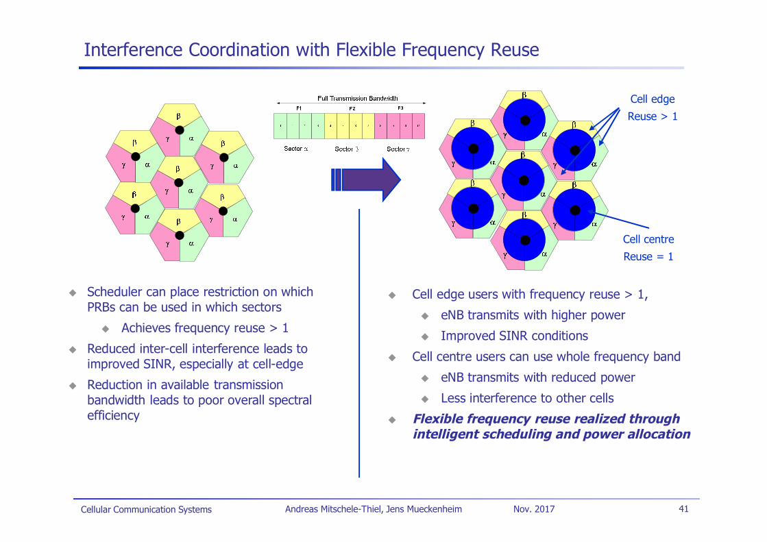
Interference Coordination with Flexible Frequency Reuse
Cell edge users with frequency reuse > 1,
eNB transmits with higher power
Improved SINR conditions
Cell centre users can use whole frequency band
eNB transmits with reduced power
Less interference to other cells
Flexible frequency reuse realized throughintelligent scheduling and power allocation
Cell edge
Reuse > 1
Cell centre
Reuse = 1
Scheduler can place restriction on whichPRBs can be used in which sectors
Achieves frequency reuse > 1
Reduced inter-cell interference leads toimproved SINR, especially at cell-edge
Reduction in available transmissionbandwidth leads to poor overall spectralefficiency
Cellular Communication Systems 42Andreas Mitschele-Thiel, Jens Mueckenheim Nov. 2017
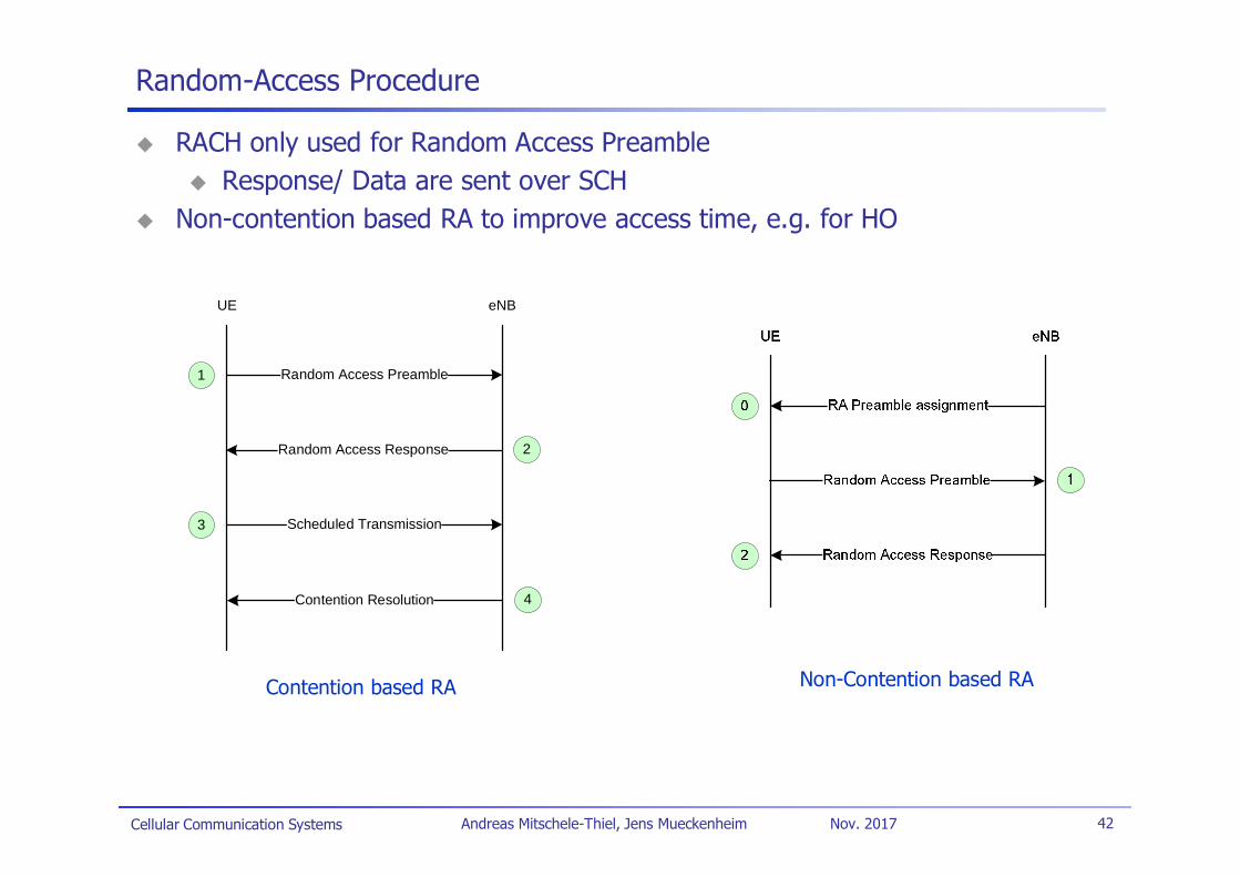
Random-Access Procedure
RACH only used for Random Access PreambleResponse/ Data are sent over SCH
Non-contention based RA to improve access time, e.g. for HO
UE eNB
Random Access Preamble1
Random Access Response 2
Scheduled Transmission3
Contention Resolution 4
Contention based RA Non-Contention based RA
Cellular Communication Systems 43Andreas Mitschele-Thiel, Jens Mueckenheim Nov. 2017
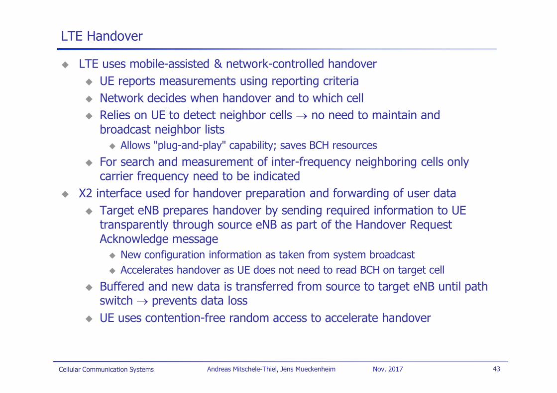
LTE Handover
LTE uses mobile-assisted & network-controlled handoverUE reports measurements using reporting criteriaNetwork decides when handover and to which cellRelies on UE to detect neighbor cells no need to maintain andbroadcast neighbor lists
Allows "plug-and-play" capability; saves BCH resources
For search and measurement of inter-frequency neighboring cells onlycarrier frequency need to be indicated
X2 interface used for handover preparation and forwarding of user dataTarget eNB prepares handover by sending required information to UEtransparently through source eNB as part of the Handover RequestAcknowledge message
New configuration information as taken from system broadcastAccelerates handover as UE does not need to read BCH on target cell
Buffered and new data is transferred from source to target eNB until pathswitch prevents data lossUE uses contention-free random access to accelerate handover
Cellular Communication Systems 44Andreas Mitschele-Thiel, Jens Mueckenheim Nov. 2017
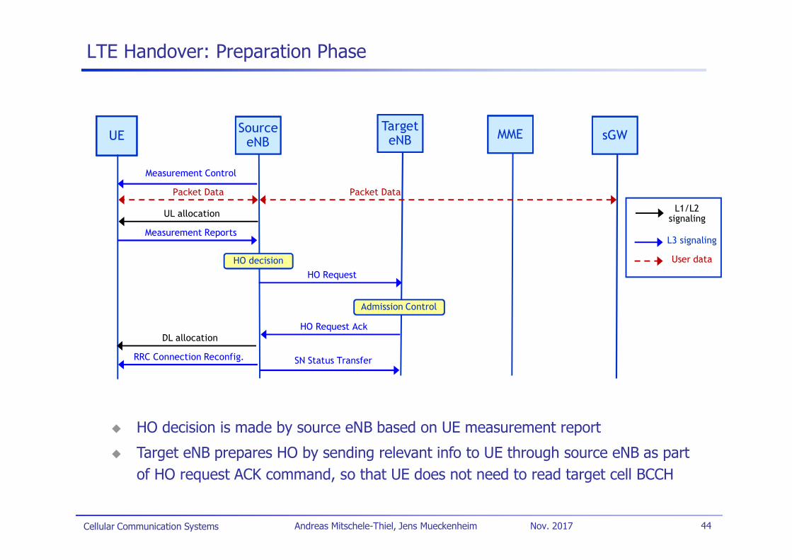
LTE Handover: Preparation Phase
UEUE SourceeNB
SourceSourceeNB
Measurement Control
TargeteNB
TargeteNB MMEMME sGWsGW
Packet Data Packet Data
UL allocation
Measurement Reports
HO decision
Admission Control
HO Request
HO Request AckDL allocation
RRC Connection Reconfig.
L1/L2signaling
L3 signaling
User data
HO decision is made by source eNB based on UE measurement report
Target eNB prepares HO by sending relevant info to UE through source eNB as partof HO request ACK command, so that UE does not need to read target cell BCCH
SN Status Transfer
Cellular Communication Systems 45Andreas Mitschele-Thiel, Jens Mueckenheim Nov. 2017
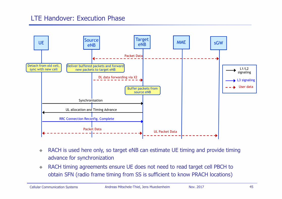
LTE Handover: Execution Phase
UEUE SourceeNB
SourceeNB
TargeteNB
TargeteNB MMEMME sGWsGW
Detach from old cell,sync with new cell
Deliver buffered packets and forwardnew packets to target eNB
DL data forwarding via X2
Synchronisation
UL allocation and Timing Advance
RRC Connection Reconfig. Complete
L1/L2signaling
L3 signaling
User dataBuffer packets fromsource eNB
Packet Data
Packet Data
RACH is used here only, so target eNB can estimate UE timing and provide timingadvance for synchronization
RACH timing agreements ensure UE does not need to read target cell PBCH toobtain SFN (radio frame timing from SS is sufficient to know PRACH locations)
UL Packet Data
Cellular Communication Systems 46Andreas Mitschele-Thiel, Jens Mueckenheim Nov. 2017
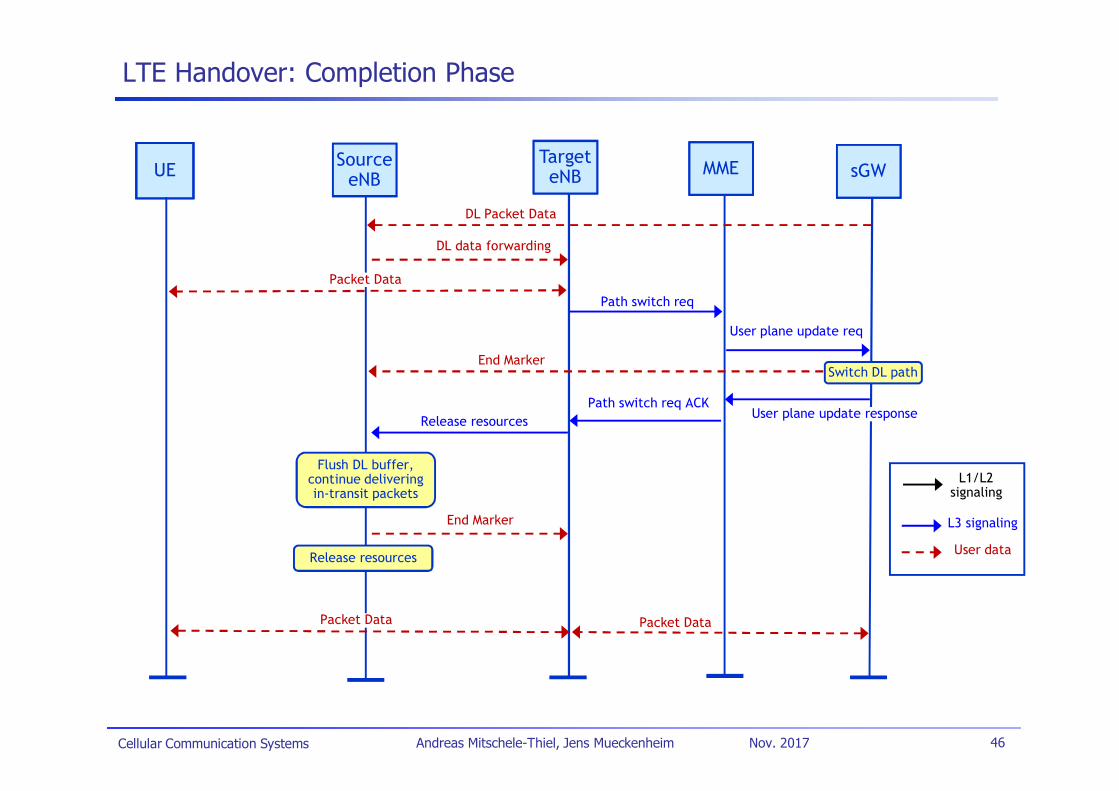
LTE Handover: Completion Phase
UEUE SourceeNB
TargeteNB
TargeteNB MMEMME sGWsGW
DL Packet Data
Path switch req
User plane update req
Switch DL path
User plane update responsePath switch req ACK
Release resources
Packet Data Packet Data
L1/L2signaling
L3 signaling
User data
DL data forwarding
Flush DL buffer,continue deliveringin-transit packets
End Marker
Release resources
Packet Data
End Marker

Cellular Communication Systems 47Andreas Mitschele-Thiel, Jens Mueckenheim Nov. 2017
LTE Handover: Illustration of Interruption Period
UL
U- plane active
U-plane active
UEUE SourceeNB
SourceeNB
TargeteNB
TargeteNB
UL
U- plane active
U-plane active
UEs stops
Rx/Tx on the old cell
DL sync
+ RACH (no contention)
+ Timing Adv
+ UL Resource Req andGrant
ACK
HO Request
HO Confirm
HandoverLatency
(approx 55 ms)approx20 ms
MeasurementReport
HO Command
HO Complete
HandoverInterruption
(approx 35 ms)
Handover Preparation
Cellular Communication Systems 48Andreas Mitschele-Thiel, Jens Mueckenheim Nov. 2017
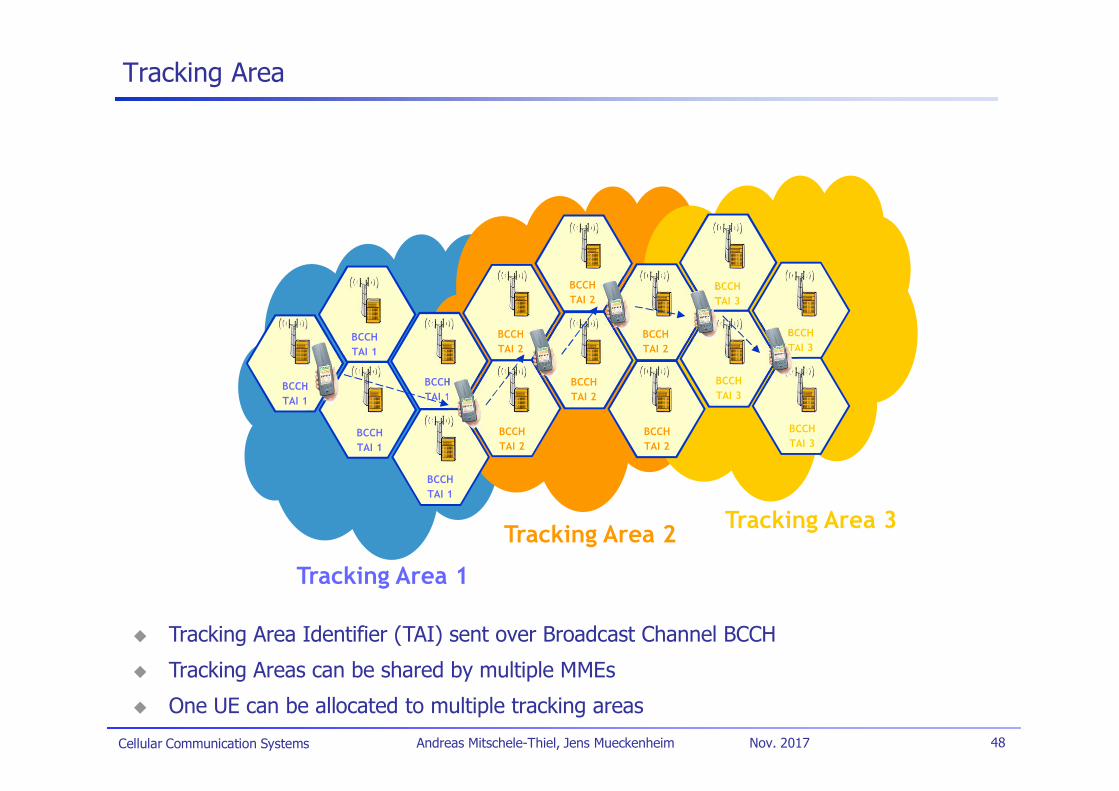
Tracking Area
BCCHTAI 1
BCCHTAI 1
BCCHTAI 1
BCCHTAI 1
BCCHTAI 1
BCCHTAI 2
BCCHTAI 2
BCCHTAI 2
BCCHTAI 2
BCCHTAI 2
BCCHTAI 2
BCCHTAI 3
BCCHTAI 3
BCCHTAI 3
BCCHTAI 3
Tracking Area 1
Tracking Area 2 Tracking Area 3
Tracking Area Identifier (TAI) sent over Broadcast Channel BCCH
Tracking Areas can be shared by multiple MMEs
One UE can be allocated to multiple tracking areas
Cellular Communication Systems 49Andreas Mitschele-Thiel, Jens Mueckenheim Nov. 2017
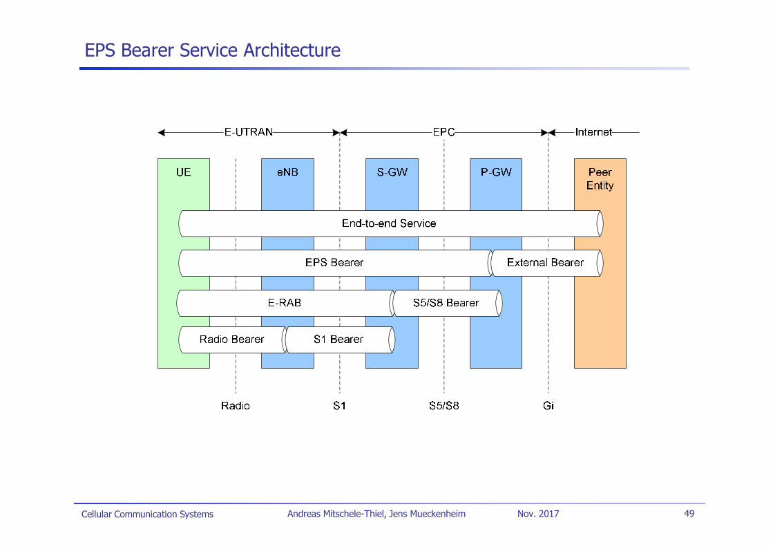
EPS Bearer Service Architecture
Cellular Communication Systems 50Andreas Mitschele-Thiel, Jens Mueckenheim Nov. 2017
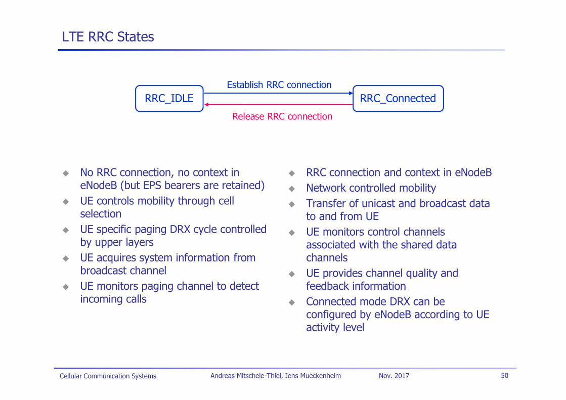
LTE RRC States
No RRC connection, no context ineNodeB (but EPS bearers are retained)UE controls mobility through cellselectionUE specific paging DRX cycle controlledby upper layersUE acquires system information frombroadcast channelUE monitors paging channel to detectincoming calls
RRC connection and context in eNodeBNetwork controlled mobilityTransfer of unicast and broadcast datato and from UEUE monitors control channelsassociated with the shared datachannelsUE provides channel quality andfeedback informationConnected mode DRX can beconfigured by eNodeB according to UEactivity level
RRC_IDLE RRC_Connected
Release RRC connection
Establish RRC connection
Cellular Communication Systems 51Andreas Mitschele-Thiel, Jens Mueckenheim Nov. 2017
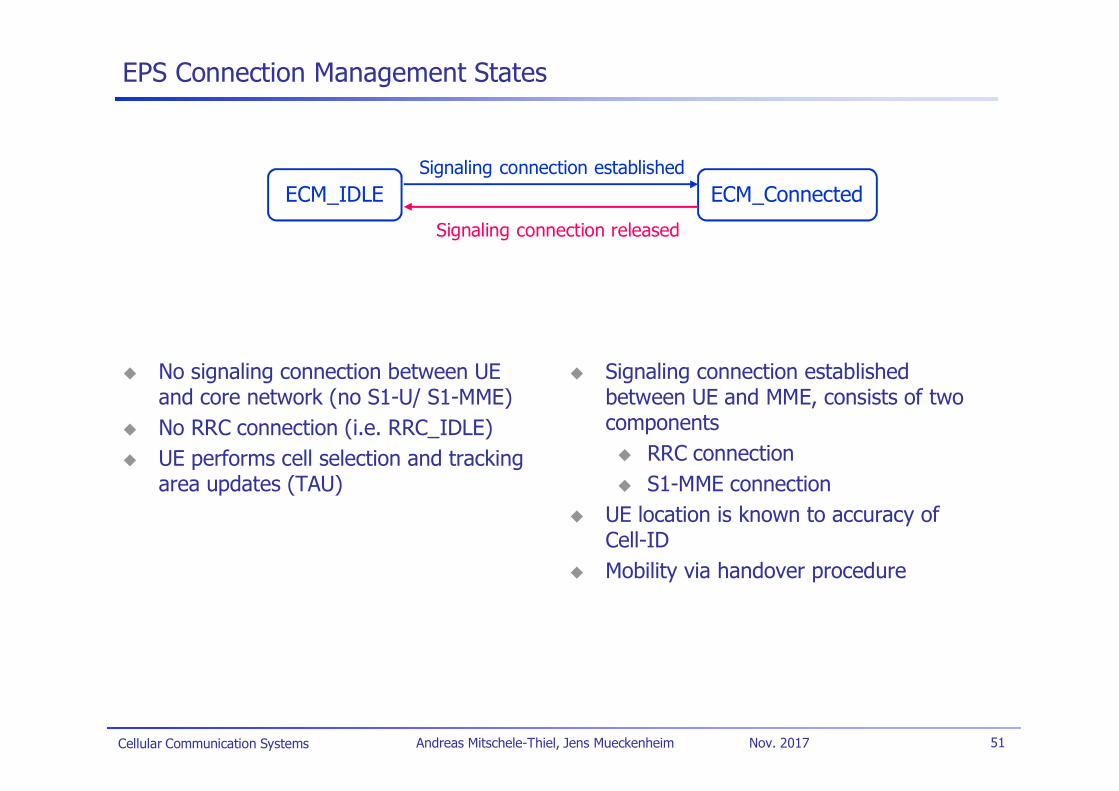
EPS Connection Management States
No signaling connection between UEand core network (no S1-U/ S1-MME)No RRC connection (i.e. RRC_IDLE)UE performs cell selection and trackingarea updates (TAU)
Signaling connection establishedbetween UE and MME, consists of twocomponents
RRC connectionS1-MME connection
UE location is known to accuracy ofCell-IDMobility via handover procedure
ECM_IDLE ECM_Connected
Signaling connection released
Signaling connection established
Cellular Communication Systems 52Andreas Mitschele-Thiel, Jens Mueckenheim Nov. 2017
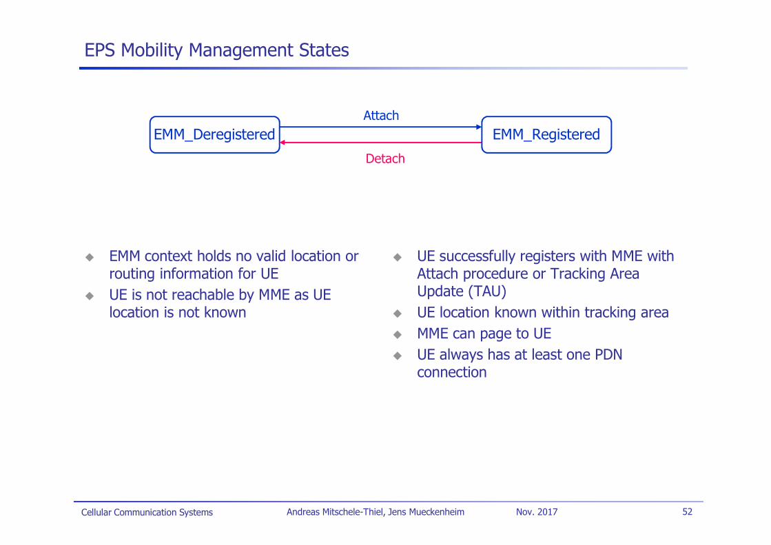
EPS Mobility Management States
EMM context holds no valid location orrouting information for UEUE is not reachable by MME as UElocation is not known
UE successfully registers with MME withAttach procedure or Tracking AreaUpdate (TAU)UE location known within tracking areaMME can page to UEUE always has at least one PDNconnection
EMM_Deregistered
Detach
AttachEMM_Registered
Cellular Communication Systems 53Andreas Mitschele-Thiel, Jens Mueckenheim Nov. 2017
LTE – Status
3GPP quickly delivered stable LTE standardsRel.8 frozen in 2Q2009
Since 2010, LTE has been deployed worldwideTotally new infrastructureFirst target was often to provide broadband coverage for fixed users
Worldwide, 560 LTE networks are in service (Oct. 2017)*
Mostly implemented according to Release 8/9, increased deployment ofLTE-AdvancedMostly FDD, but also some TDD networksMobile packet data support with fallback to 3G/2G for CS voice service,starting with VoIPSpectrum allocation in new frequency bands as well as existing 2G/3Gbands (refarming)
3GPP continues LTE developmentRel.9: technical enhancements/ E-MBMSRel.10 – 12: LTE-Advanced (cf. next slides)
*[Source: 5G Americas/TeleGeography]
Cellular Communication Systems 54Andreas Mitschele-Thiel, Jens Mueckenheim Nov. 2017
LTE-Advanced
The evolution of LTECorresponding to LTE Release 10 and beyond
Motivation of LTE-AdvancedIMT-Advanced standardisation process in ITU-RAdditional IMT spectrum band identified in WRC07Further evolution of LTE Release 8 and 9 to meet:
Performance requirements for IMT-Advanced of ITU-R
Future operator and end-user requirements
Other important requirementsLTE-Advanced to be backwards compatible with Release 8Support for flexible deployment scenarios including downlink/uplinkasymmetric bandwidth allocation for FDD and non-contiguous spectrumallocationIncreased deployment of indoor eNB and HNB in LTE-Advanced
Cf. T. Nakamura (RAN chairman): “Proposal for Candidate Radio Interface Technologies for IMT-Advanced Basedon LTE Release 10 and Beyond LTE-Advanced),” ITU-R WP 5D 3rd Workshop on IMT-Advanced, October 2009.
Cellular Communication Systems 55Andreas Mitschele-Thiel, Jens Mueckenheim Nov. 2017
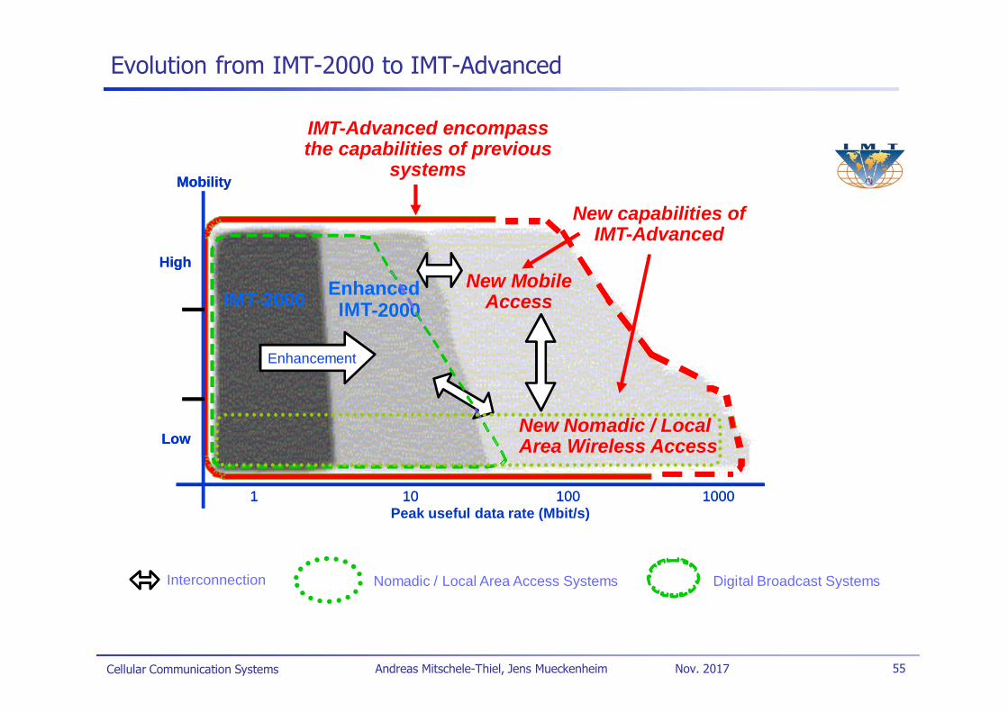
Evolution from IMT-2000 to IMT-Advanced
Interconnection
IMT-2000
Mobility
Low
High
1 10 100 1000Peak useful data rate (Mbit/s)
EnhancedIMT-2000
Enhancement
IMT-2000
Mobility
Low
High
1 10 100 1000
Area Wireless Access
EnhancedIMT-2000
Enhancement
Digital Broadcast SystemsNomadic / Local Area Access Systems
New Nomadic / Local
IMT-Advanced encompassthe capabilities of previous
systems
New capabilities ofIMT-Advanced
New MobileAccess
Cellular Communication Systems 56Andreas Mitschele-Thiel, Jens Mueckenheim Nov. 2017
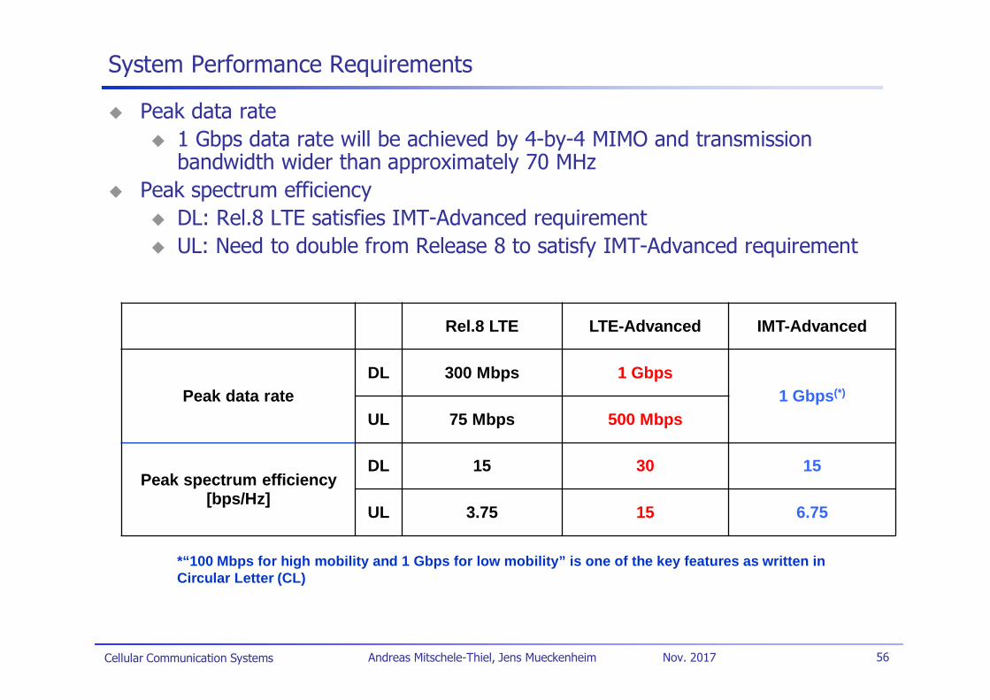
Peak data rate1 Gbps data rate will be achieved by 4-by-4 MIMO and transmissionbandwidth wider than approximately 70 MHz
Peak spectrum efficiencyDL: Rel.8 LTE satisfies IMT-Advanced requirementUL: Need to double from Release 8 to satisfy IMT-Advanced requirement
Rel.8 LTE LTE-Advanced IMT-Advanced
Peak data rateDL 300 Mbps 1 Gbps
1 Gbps(*)
UL 75 Mbps 500 Mbps
Peak spectrum efficiency[bps/Hz]
DL 15 30 15
UL 3.75 15 6.75
*“100 Mbps for high mobility and 1 Gbps for low mobility” is one of the key features as written inCircular Letter (CL)
System Performance Requirements
Cellular Communication Systems 57Andreas Mitschele-Thiel, Jens Mueckenheim Nov. 2017
Technical Outline to Achieve LTE-Advanced Requirements
Support wider bandwidthCarrier aggregation to achieve wider bandwidthSupport of spectrum aggregationPeak data rate, spectrum flexibility
Advanced MIMO techniquesExtension to up to 8-layer transmission in downlinkIntroduction of single-user MIMO up to 4-layer transmission in uplinkPeak data rate, capacity, cell-edge user throughput
Coordinated multipoint transmission and reception (CoMP)CoMP transmission in downlinkCoMP reception in uplinkCell-edge user throughput, coverage, deployment flexibility
RelayingType 1 relays create a separate cell and appear as Rel.8 LTE eNB toRel.8 LTE UEsCoverage, cost effective deployment
Cellular Communication Systems 58Andreas Mitschele-Thiel, Jens Mueckenheim Nov. 2017
Carrier Aggregation
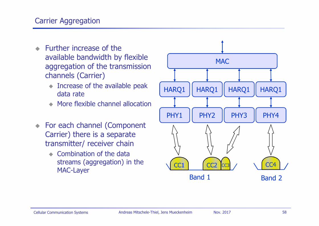
Further increase of theavailable bandwidth by flexibleaggregation of the transmissionchannels (Carrier)
Increase of the available peakdata rateMore flexible channel allocation
For each channel (ComponentCarrier) there is a separatetransmitter/ receiver chain
Combination of the datastreams (aggregation) in theMAC-Layer
MAC
HARQ1 HARQ1 HARQ1 HARQ1
PHY1 PHY2 PHY3 PHY4
CC1 CC2 CC3 CC4
Band 1 Band 2
Cellular Communication Systems 59Andreas Mitschele-Thiel, Jens Mueckenheim Nov. 2017
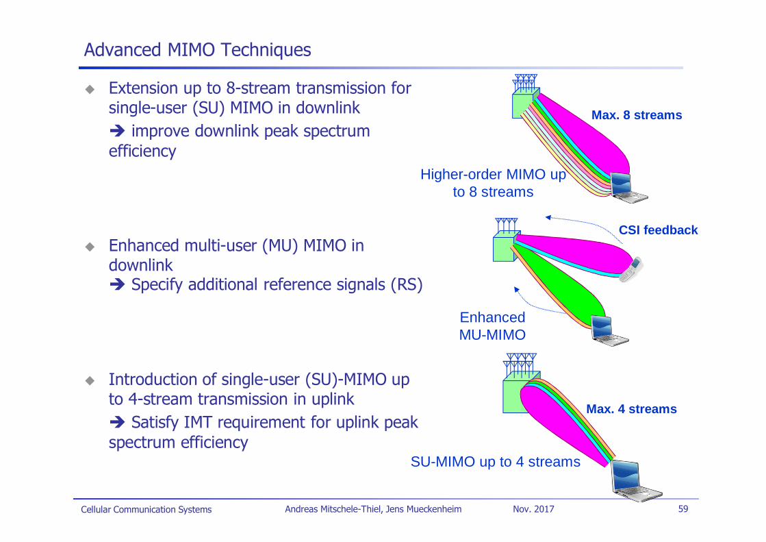
Advanced MIMO Techniques
Extension up to 8-stream transmission forsingle-user (SU) MIMO in downlink
improve downlink peak spectrumefficiency
Enhanced multi-user (MU) MIMO indownlink
Specify additional reference signals (RS)
Introduction of single-user (SU)-MIMO upto 4-stream transmission in uplink
Satisfy IMT requirement for uplink peakspectrum efficiency
Max. 8 streams
Higher-order MIMO upto 8 streams
EnhancedMU-MIMO
CSI feedback
Max. 4 streams
SU-MIMO up to 4 streams
Cellular Communication Systems 60Andreas Mitschele-Thiel, Jens Mueckenheim Nov. 2017
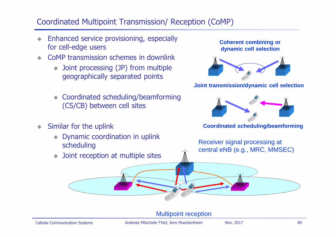
Coordinated Multipoint Transmission/ Reception (CoMP)
Enhanced service provisioning, especiallyfor cell-edge usersCoMP transmission schemes in downlink
Joint processing (JP) from multiplegeographically separated points
Coordinated scheduling/beamforming(CS/CB) between cell sites
Similar for the uplinkDynamic coordination in uplinkschedulingJoint reception at multiple sites
Coherent combining ordynamic cell selection
Joint transmission/dynamic cell selection
Coordinated scheduling/beamforming
Receiver signal processing atcentral eNB (e.g., MRC, MMSEC)
Multipoint reception
Cellular Communication Systems 61Andreas Mitschele-Thiel, Jens Mueckenheim Nov. 2017
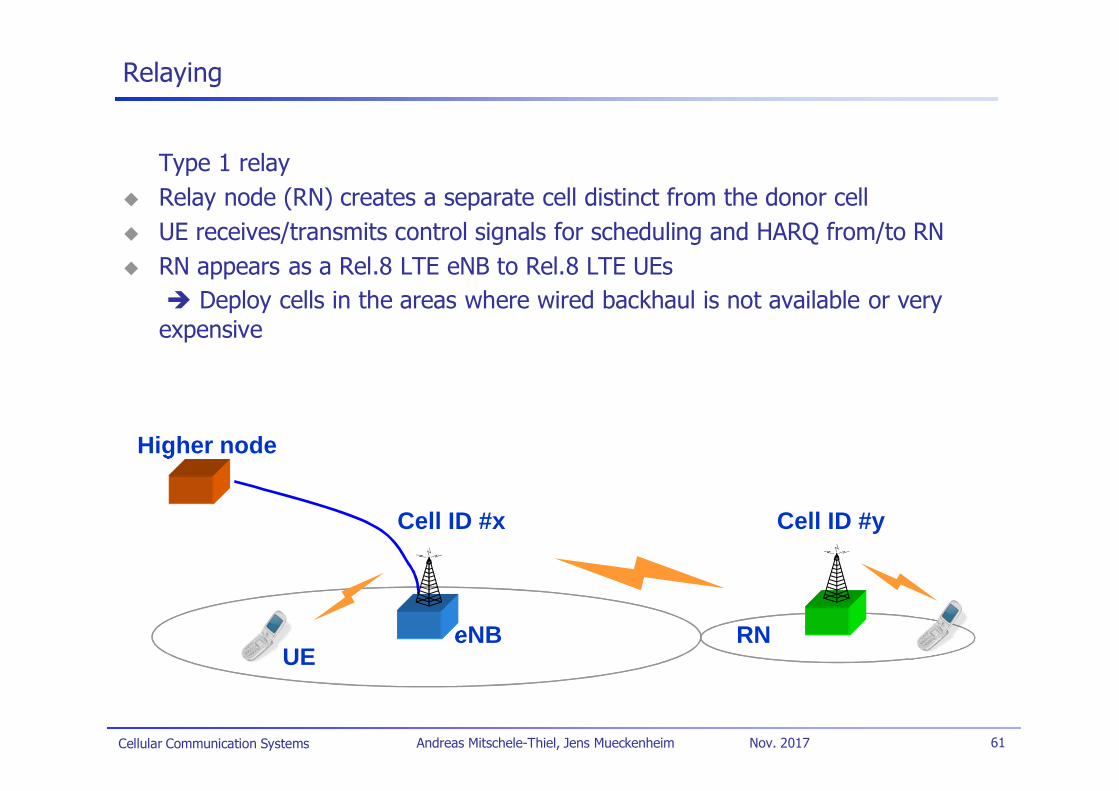
eNB RNUE
Cell ID #x Cell ID #y
Higher node
Relaying
Type 1 relayRelay node (RN) creates a separate cell distinct from the donor cellUE receives/transmits control signals for scheduling and HARQ from/to RNRN appears as a Rel.8 LTE eNB to Rel.8 LTE UEs
Deploy cells in the areas where wired backhaul is not available or veryexpensive
Cellular Communication Systems 62Andreas Mitschele-Thiel, Jens Mueckenheim Nov. 2017
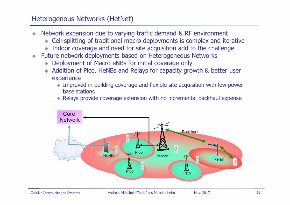
Heterogenous Networks (HetNet)
Network expansion due to varying traffic demand & RF environmentCell-splitting of traditional macro deployments is complex and iterativeIndoor coverage and need for site acquisition add to the challenge
Future network deployments based on Heterogeneous NetworksDeployment of Macro eNBs for initial coverage onlyAddition of Pico, HeNBs and Relays for capacity growth & better userexperience
Improved in-building coverage and flexible site acquisition with low powerbase stationsRelays provide coverage extension with no incremental backhaul expense
Cellular Communication Systems 63Andreas Mitschele-Thiel, Jens Mueckenheim Nov. 2017
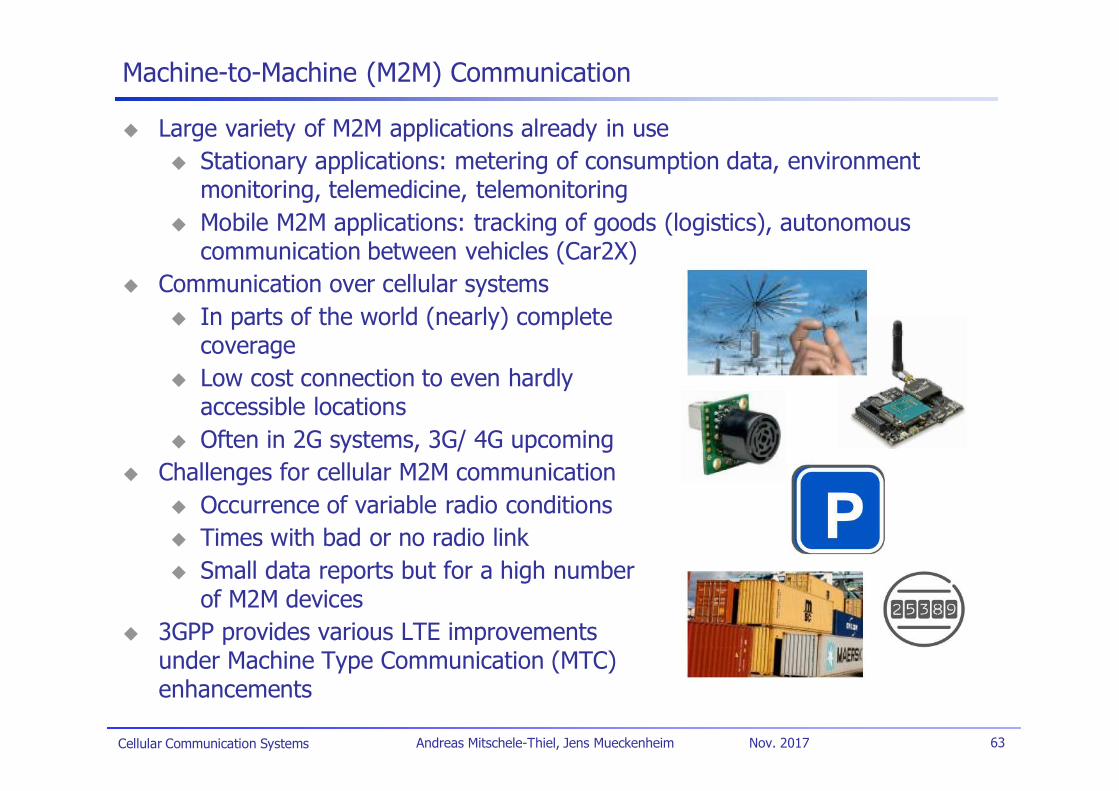
Machine-to-Machine (M2M) Communication
Large variety of M2M applications already in useStationary applications: metering of consumption data, environmentmonitoring, telemedicine, telemonitoringMobile M2M applications: tracking of goods (logistics), autonomouscommunication between vehicles (Car2X)
Communication over cellular systemsIn parts of the world (nearly) completecoverageLow cost connection to even hardlyaccessible locationsOften in 2G systems, 3G/ 4G upcoming
Challenges for cellular M2M communicationOccurrence of variable radio conditionsTimes with bad or no radio linkSmall data reports but for a high numberof M2M devices
3GPP provides various LTE improvementsunder Machine Type Communication (MTC)enhancements
Cellular Communication Systems 64Andreas Mitschele-Thiel, Jens Mueckenheim Nov. 2017
Device-to-Device (D2D) Communication
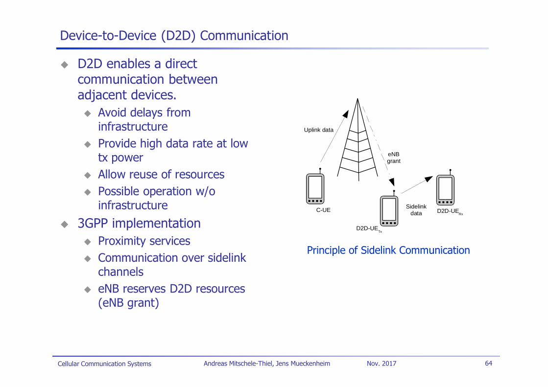
D2D enables a directcommunication betweenadjacent devices.
Avoid delays frominfrastructureProvide high data rate at lowtx powerAllow reuse of resourcesPossible operation w/oinfrastructure
3GPP implementationProximity servicesCommunication over sidelinkchannelseNB reserves D2D resources(eNB grant)
D2D-UETx
D2D-UERx
C-UE
Uplink data
eNBgrant
Sidelinkdata
Principle of Sidelink Communication
Cellular Communication Systems 65Andreas Mitschele-Thiel, Jens Mueckenheim Nov. 2017
LTE References
Literature:H. Holma/ A. Toskala (Ed.): “LTE for UMTS - Evolution to LTE-Advanced,”2nd edition, Wiley 2011E. Dahlman et al: “4G: LTE/LTE-Advanced for Mobile Broadband,” 2nd edition,Academic Press 2013S. Sesia et al: “LTE, The UMTS Long Term Evolution: From Theory to Practice,”2nd edition, Wiley 2011H. Holma/ A. Toskala (Ed.): “LTE Advanced: 3GPP Solution for IMT-Advanced,”Wiley 2012
StandardsTS 36.xxx series: RAN AspectsTS 36.300 “E-UTRAN; Overall description; Stage 2”TR 25.912 “Feasibility study for evolved Universal Terrestrial Radio Access (UTRA)and Universal Terrestrial Radio Access Network (UTRAN)”TR 25.814 “Physical layer aspect for evolved UTRA”TR 23.882 “3GPP System Architecture Evolution: Report on Technical Options andConclusions”TR 36.912 “Feasibility study for Further Advancements for E-UTRA (LTE-Advanced)”TR 36.814 “Further Advancements for E-UTRA – Physical Layer Aspects”
Cellular Communication Systems 66Andreas Mitschele-Thiel, Jens Mueckenheim Nov. 2017
Abbreviations
CP Cyclic PrefixDFT Discrete Fourier TransformationDRX Discontinuous ReceptionECM EPS Connection ManagementEMM EPS Mobility ManagementeNodeB/eNB Evolved NodeBEPC Evolved Packet CoreEPS Evolved Packet SystemE-UTRAN Evolved UMTS Terrestrial Radio Access
NetworkFDD Frequency-Division DuplexFDM Frequency-Division MultiplexingFFT Fast Fourier TransformationHD-FDD Half-Duplex FDDHO HandoverHOM Higher Order ModulationHSS Home Subscriber ServerIFFT Inverse FFTISI Inter-Symbol InterferenceLTE Long Term EvolutionMIMO Multiple-Input Multiple-OutputMME Mobility Management EntityMU Multi-User
OFDM Orthogonal Frequency-DivisionMultiplexing
OFDMA Orthogonal Frequency-DivisionMultiple-Access
PCRF Policy & Charging FunctionPDN Packet Data NetworkP-GW PDN GatewayRA Random AccessRB Resource BlockRRC Radio Resource ControlSAE System Architecture EvolutionSCH Shared ChannelS-GW Serving GatewaySC-FDMA Single Carrier FDMASON Self-Organizing NetworkSS Synchronization SignalSU Single UserTDD Time-Division DuplexTA Timing Advance/ Tracking AreaTAI Tracking Area IndicatorTAU Tracking Area UpdateUE User EquipmentVoIP Voice over Internet Protocol