Embed Size (px)
Citation preview
All rights reserved © 2006, AlcatelUlrich Barth
3GPP Long-Term Evolution / System Architecture EvolutionOverview
September 2006
All rights reserved © 2006, Alcatel3GPP LTE/SAE Overview / Sept. 06 / U.Barth
2
Outline
3G-LTE Introduction�Motivation
�Workplan
� Requirements
LTE air-interface
LTE Architecture
SAE Architecture
All rights reserved © 2006, Alcatel3GPP LTE/SAE Overview / Sept. 06 / U.Barth
3
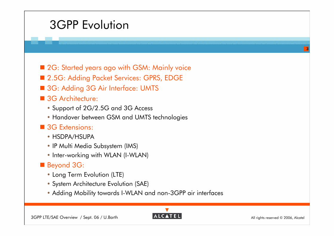
3GPP Evolution
� 2G: Started years ago with GSM: Mainly voice
� 2.5G: Adding Packet Services: GPRS, EDGE
� 3G: Adding 3G Air Interface: UMTS
� 3G Architecture:
� Support of 2G/2.5G and 3G Access
� Handover between GSM and UMTS technologies
� 3G Extensions:
� HSDPA/HSUPA
� IP Multi Media Subsystem (IMS)
� Inter-working with WLAN (I-WLAN)
� Beyond 3G:
� Long Term Evolution (LTE)
� System Architecture Evolution (SAE)
� Adding Mobility towards I-WLAN and non-3GPP air interfaces
All rights reserved © 2006, Alcatel3GPP LTE/SAE Overview / Sept. 06 / U.Barth
4
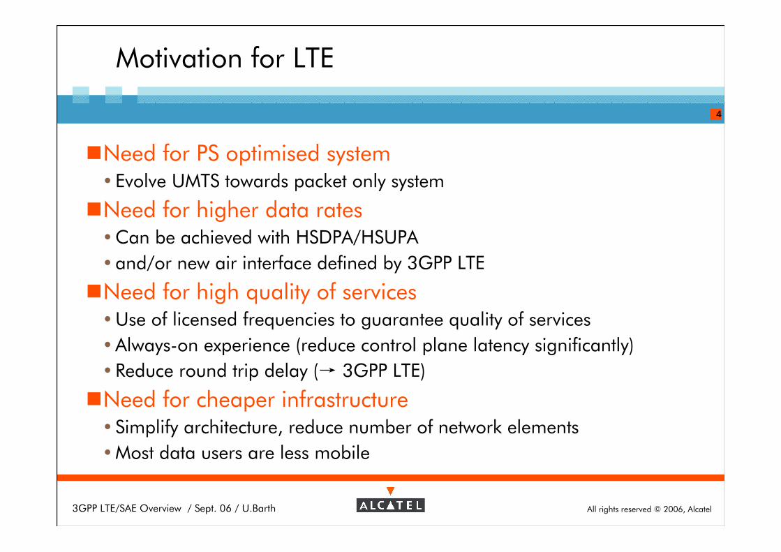
�Need for PS optimised system� Evolve UMTS towards packet only system
�Need for higher data rates�Can be achieved with HSDPA/HSUPA
� and/or new air interface defined by 3GPP LTE
�Need for high quality of services�Use of licensed frequencies to guarantee quality of services
� Always-on experience (reduce control plane latency significantly)
� Reduce round trip delay (→ 3GPP LTE)
�Need for cheaper infrastructure� Simplify architecture, reduce number of network elements
�Most data users are less mobile
Motivation for LTE
All rights reserved © 2006, Alcatel3GPP LTE/SAE Overview / Sept. 06 / U.Barth
5
LTE history - Workplan
Kick-off in RAN LTE workshop: Toronto, Nov. 2004
Study Item: TR feasibility on system level (Dec 2004 – June 2006)
� TR 25.913: Requirements for E-UTRAN
� TR 25.813: EUTRA and EUTRAN radio interface protocol aspects
� TR 25.814: Physical layer aspects for E-UTRA
� TR 25.912: Feasibility Study for Evolved UTRA and UTRAN
Detailed standard work: - June 2007
First products deployed … 2010
All rights reserved © 2006, Alcatel3GPP LTE/SAE Overview / Sept. 06 / U.Barth
6
RAN-LTE concept: Requirements
3GPP TR 25.913
� Service related requirements:
� support of available and future advanced services VoIP
� higher peak data rates (e.g. 100 Mbps DL, 50 Mbps UL)
� U-Plane /C-Plane latency: transit time (<10ms); setup times (<100ms)
� Radio related requirements:
� improved “cell edge rates” and spectral efficiency (e.g. 2-4 x Rel6)
� improved inner cell average data throughputs (MIMO needed)
� Scaleable bandwidth - 1.25, 1.6, 2.5, 5, 10, 15, 20 MHz
� Cost related requirements: reduced CAPEX and OPEX imply
� less complexity in RAN (architecture, signaling procedures/protocols)
� economic usage of backhaul capacity; simplified and unified transport (IP)
� Compatibility Requirements:
� interworking with legacy 3G and cost effective migration
All rights reserved © 2006, Alcatel3GPP LTE/SAE Overview / Sept. 06 / U.Barth
7
Outline
3G-LTE Introduction
LTE air-interface �Modulation / Multiple Access
�Multiple Antenna Schemes
� Scheduling
LTE Architecture
SAE Architecture
All rights reserved © 2006, Alcatel3GPP LTE/SAE Overview / Sept. 06 / U.Barth
8
3GPP LTE PHY
Modulation / Multiple Access�Downlink: OFDM / OFDMA
� Allows simple receivers in the terminal in case of large bandwidth
� #subcarriers scales with bandwidth (76 ... 1201)
� frequency selective scheduling in DL (i.e. OFDMA)
� Adaptive modulation and coding (up to 64-QAM)
�Uplink: SC-FDMA (Single Carrier - Frequency Division Multiple Access)
� A FFT-based transmission scheme like OFDM
� But with better PAPR (Peak-to-Average Power Ratio)
� The total bandwidth is divided into a small number of frequency blocks to be assigned to the UEs (e.g., 15 blocks for a 5 MHz bandwidth)
� With Guard Interval (Cyclic Prefix) for easy Frequency Domain Equalisation (FDE) at receiver
All rights reserved © 2006, Alcatel3GPP LTE/SAE Overview / Sept. 06 / U.Barth
9
3GPP LTE PHY
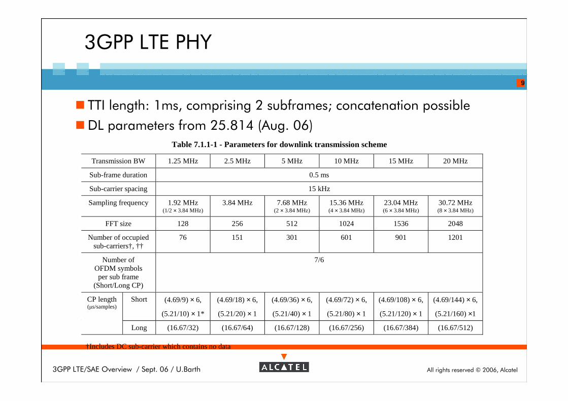
� TTI length: 1ms, comprising 2 subframes; concatenation possible
�DL parameters from 25.814 (Aug. 06)
Table 7.1.1-1 - Parameters for downlink transmission scheme
Transmission BW 1.25 MHz 2.5 MHz 5 MHz 10 MHz 15 MHz 20 MHz
Sub-frame duration 0.5 ms
Sub-carrier spacing 15 kHz
Sampling frequency 1.92 MHz(1/2 × 3.84 MHz)
3.84 MHz 7.68 MHz(2 × 3.84 MHz)
15.36 MHz(4 × 3.84 MHz)
23.04 MHz(6 × 3.84 MHz)
30.72 MHz(8 × 3.84 MHz)
FFT size 128 256 512 1024 1536 2048
Number of occupiedsub-carriers†, ††
76 151 301 601 901 1201
Number ofOFDM symbolsper sub frame
(Short/Long CP)
7/6
Short (4.69/9) × 6,
(5.21/10) × 1*
(4.69/18) × 6,
(5.21/20) × 1
(4.69/36) × 6,
(5.21/40) × 1
(4.69/72) × 6,
(5.21/80) × 1
(4.69/108) × 6,
(5.21/120) × 1
(4.69/144) × 6,
(5.21/160) ×1
CP length(µs/samples)
Long (16.67/32) (16.67/64) (16.67/128) (16.67/256) (16.67/384) (16.67/512)
†Includes DC sub-carrier which contains no data
All rights reserved © 2006, Alcatel3GPP LTE/SAE Overview / Sept. 06 / U.Barth
10
3GPP LTE PHY – Multiple Antenna Schemes
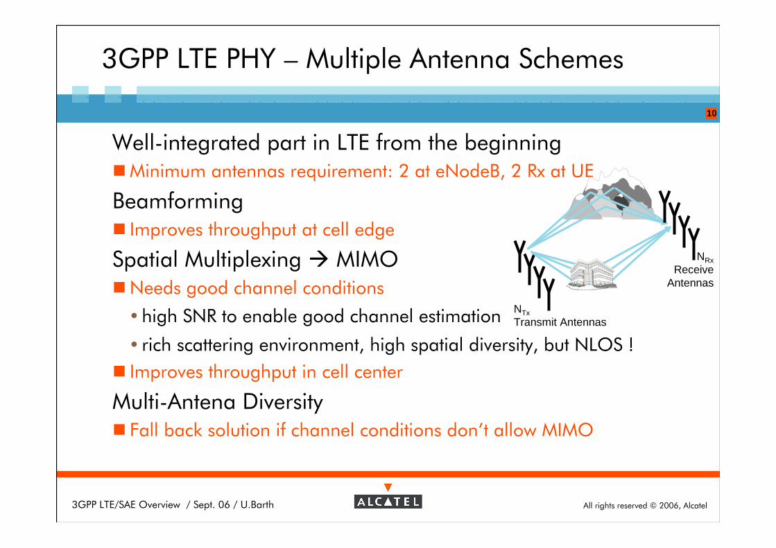
Well-integrated part in LTE from the beginning�Minimum antennas requirement: 2 at eNodeB, 2 Rx at UE
Beamforming� Improves throughput at cell edge
Spatial Multiplexing � MIMO�Needs good channel conditions
� high SNR to enable good channel estimation
� rich scattering environment, high spatial diversity, but NLOS !
� Improves throughput in cell center
Multi-Antena Diversity� Fall back solution if channel conditions don’t allow MIMO
NTxTransmit Antennas
NRxReceive
Antennas
All rights reserved © 2006, Alcatel3GPP LTE/SAE Overview / Sept. 06 / U.Barth
11
3GPP LTE PHY - MIMO Basics
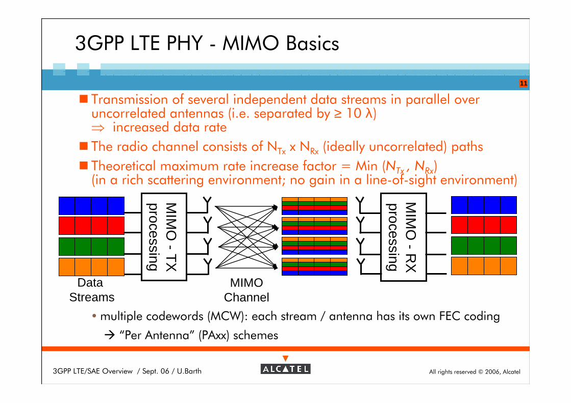
� Transmission of several independent data streams in parallel over uncorrelated antennas (i.e. separated by ≥ 10 λ) ⇒ increased data rate
� The radio channel consists of NTx x NRx (ideally uncorrelated) paths
� Theoretical maximum rate increase factor = Min (NTx , NRx)(in a rich scattering environment; no gain in a line-of-sight environment)
� multiple codewords (MCW): each stream / antenna has its own FEC coding
� “Per Antenna” (PAxx) schemes
MIM
O -
RX
processing
Data Streams
MIMOChannel
MIM
O -
TX
processing
All rights reserved © 2006, Alcatel3GPP LTE/SAE Overview / Sept. 06 / U.Barth
12
3GPP LTE PHY - Scheduling
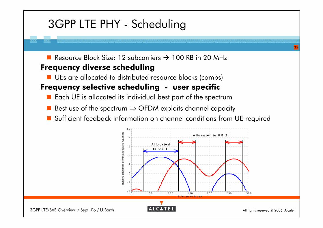
� Resource Block Size: 12 subcarriers � 100 RB in 20 MHz
Frequency diverse scheduling
� UEs are allocated to distributed resource blocks (combs)
Frequency selective scheduling - user specific
� Each UE is allocated its individual best part of the spectrum
� Best use of the spectrum ⇒ OFDM exploits channel capacity
� Sufficient feedback information on channel conditions from UE required
0 5 0 10 0 1 50 2 0 0 2 50 3 0 0- 4
- 2
0
2
4
6
8
1 0
S ub c a rr ie r in d e x
Re
lativ
e s
ub
carr
ier
pow
er
at
rece
ivin
g U
E i
n dB
A l lo ca te d
to U E 1
A llo ca te d to U E 2
All rights reserved © 2006, Alcatel3GPP LTE/SAE Overview / Sept. 06 / U.Barth
13
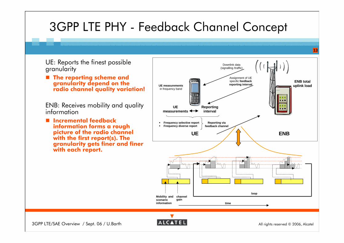
3GPP LTE PHY - Feedback Channel Concept
Mobility andscenarioinformation
channelgain
loop
time
Downlink data (signalling /traffic)
Assignment of UE specific feedback reporting interval UE measurements
in frequency band
ENB total uplink load
UE measurements
Reporting interval
� Frequency selective report � Frequency diverse report
Reporting via feedback channel
ENB UE
UE: Reports the finest possible granularity
� The reporting scheme and granularity depend on the radio channel quality variation!
ENB: Receives mobility and quality information
� Incremental feedback information forms a rough picture of the radio channel with the first report(s). The granularity gets finer and finer with each report.
All rights reserved © 2006, Alcatel3GPP LTE/SAE Overview / Sept. 06 / U.Barth
14
Outline
3G-LTE Introduction
LTE air-interface
LTE Architecture�Node Architecture
�User plane
�Control plane
SAE Architecture
All rights reserved © 2006, Alcatel3GPP LTE/SAE Overview / Sept. 06 / U.Barth
15
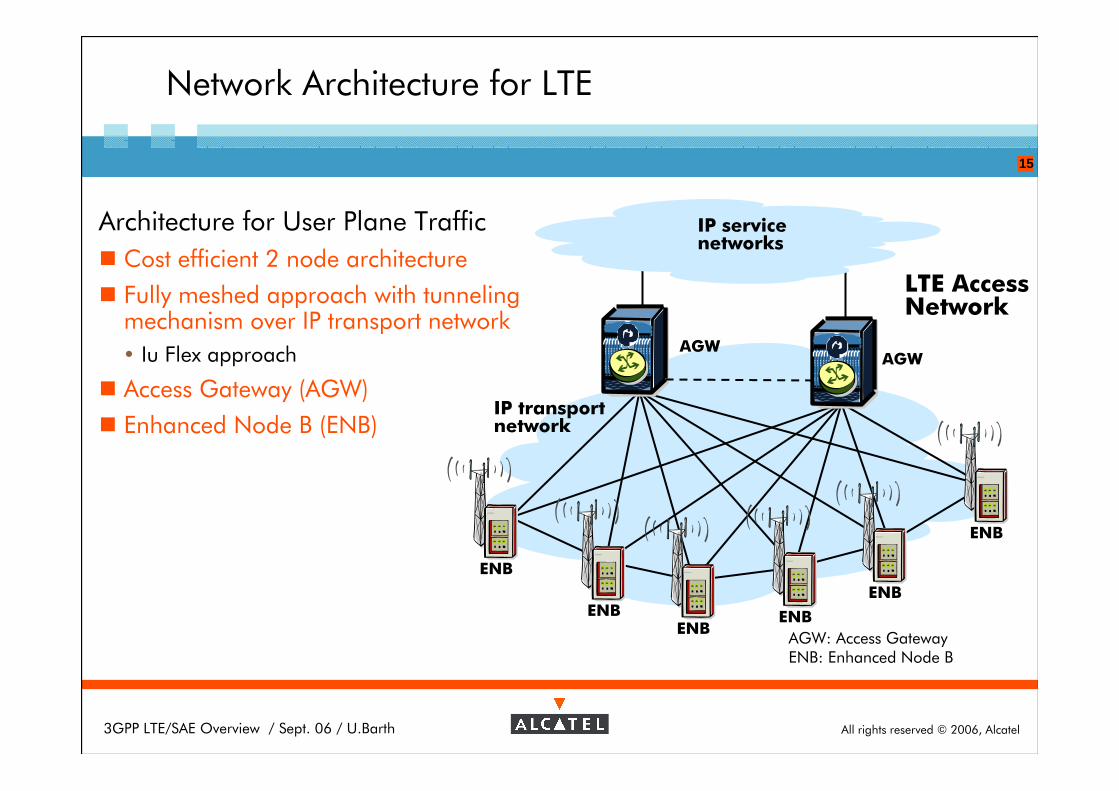
Network Architecture for LTE
Architecture for User Plane Traffic
� Cost efficient 2 node architecture
� Fully meshed approach with tunnelingmechanism over IP transport network
� Iu Flex approach
� Access Gateway (AGW)
� Enhanced Node B (ENB)
AGWAGW
AGW: Access GatewayENB: Enhanced Node B
LTE AccessNetwork
IP transportnetwork
ENB
ENBENB
ENB
ENB
ENB
IP servicenetworks
All rights reserved © 2006, Alcatel3GPP LTE/SAE Overview / Sept. 06 / U.Barth
16
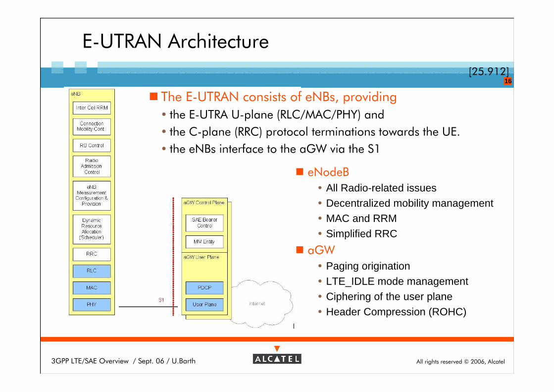
E-UTRAN Architecture
[25.912]
� The E-UTRAN consists of eNBs, providing
� the E-UTRA U-plane (RLC/MAC/PHY) and
� the C-plane (RRC) protocol terminations towards the UE.
� the eNBs interface to the aGW via the S1
� eNodeB
� All Radio-related issues
� Decentralized mobility management� MAC and RRM
� Simplified RRC
� aGW
� Paging origination
� LTE_IDLE mode management� Ciphering of the user plane
� Header Compression (ROHC)
All rights reserved © 2006, Alcatel3GPP LTE/SAE Overview / Sept. 06 / U.Barth
17
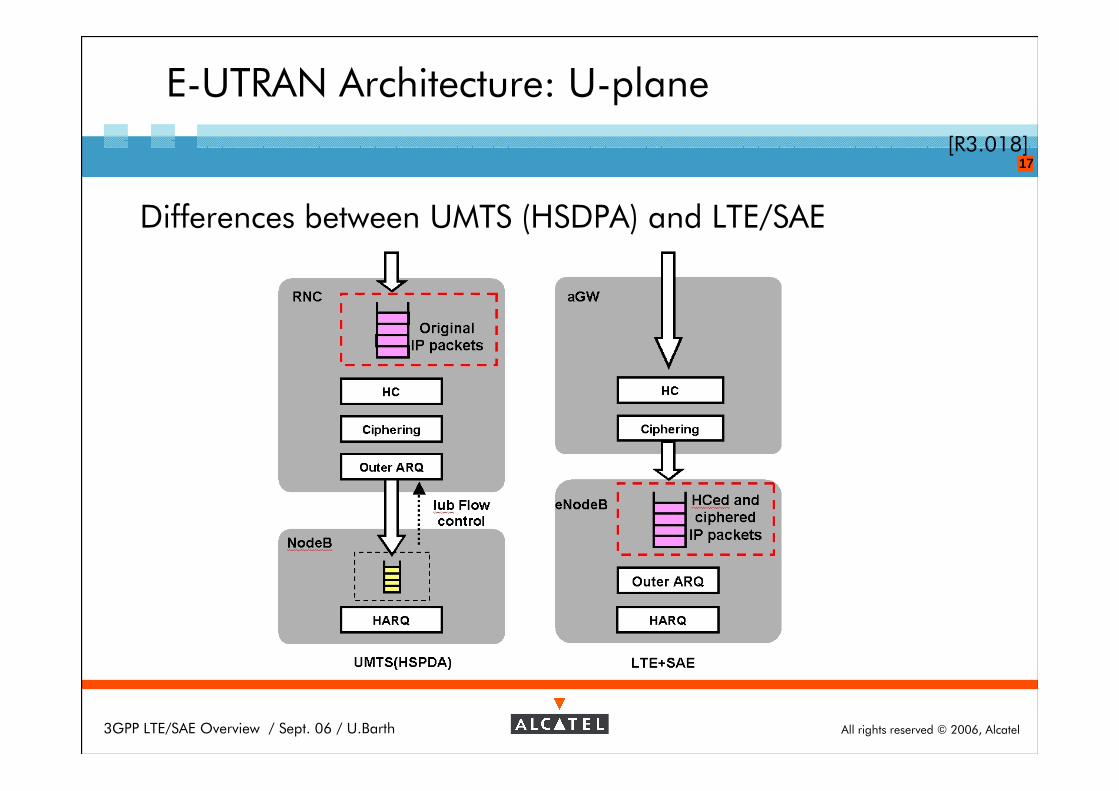
E-UTRAN Architecture: U-plane
[R3.018]
Differences between UMTS (HSDPA) and LTE/SAE
All rights reserved © 2006, Alcatel3GPP LTE/SAE Overview / Sept. 06 / U.Barth
18
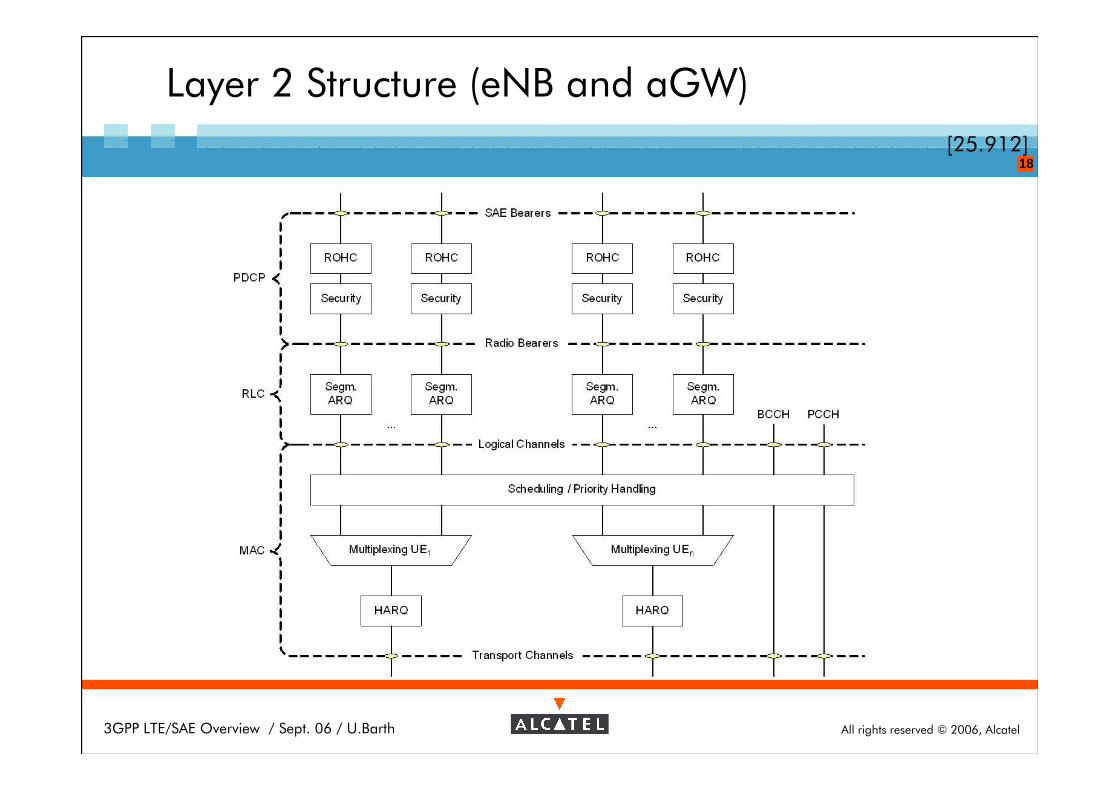
Layer 2 Structure (eNB and aGW)
[25.912]
All rights reserved © 2006, Alcatel3GPP LTE/SAE Overview / Sept. 06 / U.Barth
19
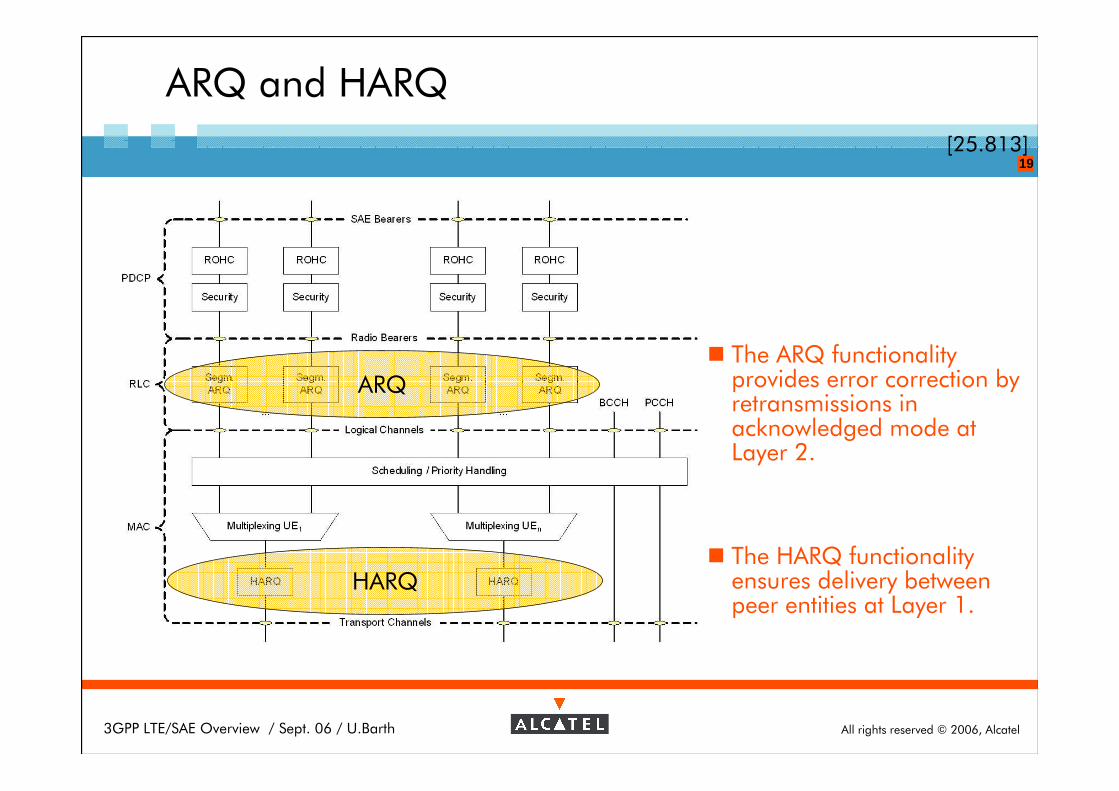
ARQ and HARQ
[25.813]
ARQ
HARQ
� The ARQ functionalityprovides error correction byretransmissions in acknowledged mode at Layer 2.
� The HARQ functionalityensures delivery betweenpeer entities at Layer 1.
All rights reserved © 2006, Alcatel3GPP LTE/SAE Overview / Sept. 06 / U.Barth
20
ARQ and HARQ
HARQ characteristics�N-process Stop-And-Wait HARQ is used
� The HARQ is based on ACK/NACKs
� In the downlink asynchronous retransmissions with adaptive transmission parameters are supported
� In the uplink HARQ is based on synchronous retransmissions
ARQ characteristics� The ARQ retransmits RLC SDUs (IP packets)
�ARQ retransmissions are based on HARQ/ARQ interactions
HARQ/ARQ interactions�ARQ uses knowledge obtained from the HARQ about thetransmission/reception status of a Transport Block
[25.813]
All rights reserved © 2006, Alcatel3GPP LTE/SAE Overview / Sept. 06 / U.Barth
21
E-UTRAN C-Plane: Distributed RRM
� Radio Bearer Control (RBC)
� Radio Admission Control (RAC)
�Connection Mobility Control (CMC)
�Dynamic Resource Allocation (scheduling) (DRA)
� Radio Configuration (RC)
References for Distributed RRM
� R2-052905 RRM for Architecture Option C in the Control Plane and Option A in the User Plane
� R3-051248 Definition of Multi- and Intra-cell RRM
� R3-060029 Handling of RRM in a Decentralized RAN Architecture
All rights reserved © 2006, Alcatel3GPP LTE/SAE Overview / Sept. 06 / U.Barth
22
E-UTRAN C-Plane: Intra-LTE Handover
� Network controlled handover: decision taken by Source ENB
� Preparation phase
� preparation of Target eNodeB by context transfer prior to HO command
� Break before make approach
� core network not involved during preparation phase
� Temporary forwarding of UP data from Source ENB to Target ENB
� Path switching at AGW
� after establishment of new connection between UE and Target ENB
� no temporary buffering at AGW
� Performance
� short interruption time in the range of 30 ms
� same handover procedure applicable for real-time (delay sensitive) and non real-time (non delay sensitive) services
� suitable for lossless and seamless handovers
All rights reserved © 2006, Alcatel3GPP LTE/SAE Overview / Sept. 06 / U.Barth
23
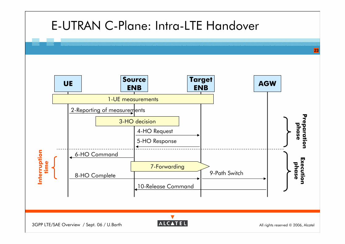
E-UTRAN C-Plane: Intra-LTE Handover
5-HO Response
UESource
ENBTargetENB
AGW
1-UE measurements
2-Reporting of measurements
3-HO decision
4-HO Request
8-HO Complete 9-Path Switch
6-HO Command
10-Release Command
7-Forwarding
Inte
rru
pti
on
tim
eP
rep
ara
tion
ph
ase
Execu
tion
ph
ase
All rights reserved © 2006, Alcatel3GPP LTE/SAE Overview / Sept. 06 / U.Barth
24
Outline
3G-LTE Introduction
LTE air-interface
LTE Architecture
SAE Architecture�Objectives
�Node Architecture
All rights reserved © 2006, Alcatel3GPP LTE/SAE Overview / Sept. 06 / U.Barth
25
System Architecture Evolution
Objectives �New core network architecture to support the high-throughput / low-latency LTE access system
� Simplified network architecture
� All IP network
� All services are via PS domain only, No CS domain
� Support mobility between multiple heterogeneous access system
� 2G/3G, LTE, non 3GPP access systems (e.g. WLAN, WiMAX)
� Inter-3GPP handover (GPRS <> E-UTRAN): Using GTP-C based interface for exchange of Radio info/context to prepare handover
� Inter 3GPP non-3GPP mobility: Evaluation of host based (MIPv4, MIPv6, DSMIPv6) and network based (NetLMM, PMIPv4, PMIPv6) protocols
All rights reserved © 2006, Alcatel3GPP LTE/SAE Overview / Sept. 06 / U.Barth
26
S5b
Evolved Packet Core
WLAN 3GPP IP Access
S2
non 3GPP IP Access
S2
IASA
S5a
SAE Anchor
3GPP Anchor
S4
SGi Evolved RAN
S1
Op. IP
Serv. (IMS, PSS, etc…)
Rx+
GERAN
UTRAN
Gb
Iu
S3
MME UPE
HSS
PCRF
S7
S6
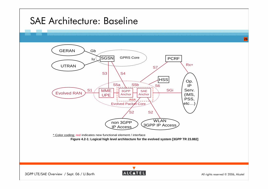
* Color coding: red indicates new functional element / interface
SGSN GPRS Core
Figure 4.2-1: Logical high level architecture for the evolved system [3GPP TR 23.882]
SAE Architecture: Baseline
All rights reserved © 2006, Alcatel3GPP LTE/SAE Overview / Sept. 06 / U.Barth
27
SAE Architecture: Functions per Element
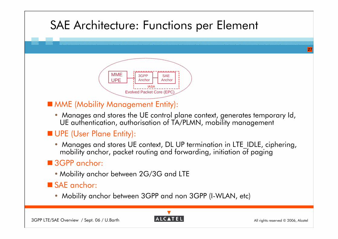
�MME (Mobility Management Entity):
� Manages and stores the UE control plane context, generates temporary Id, UE authentication, authorisation of TA/PLMN, mobility management
�UPE (User Plane Entity):
� Manages and stores UE context, DL UP termination in LTE_IDLE, ciphering, mobility anchor, packet routing and forwarding, initiation of paging
� 3GPP anchor:
� Mobility anchor between 2G/3G and LTE
� SAE anchor:
� Mobility anchor between 3GPP and non 3GPP (I-WLAN, etc)
Evolved Packet Core (EPC)IASA
SAE Anchor
3GPP Anchor
MMEUPE
All rights reserved © 2006, Alcatel3GPP LTE/SAE Overview / Sept. 06 / U.Barth
28
S5b
Evolved Packet Core
WLAN 3GPP IP Access
S2
non 3GPP IP Access
S2
IASA
S5a
SAE Anchor
3GPP Anchor
S4
SGi Evolved RAN
S1
Op. IP
Serv. (IMS, PSS, etc…)
Rx+
GERAN
UTRAN
Gb
Iu
S3
MME UPE
HSS
PCRF
S7
S6
* Color coding: red indicates new functional element / interface
SGSN GPRS Core
Figure 4.2-1: Logical high level architecture for the evolved system [3GPP TR 23.882]
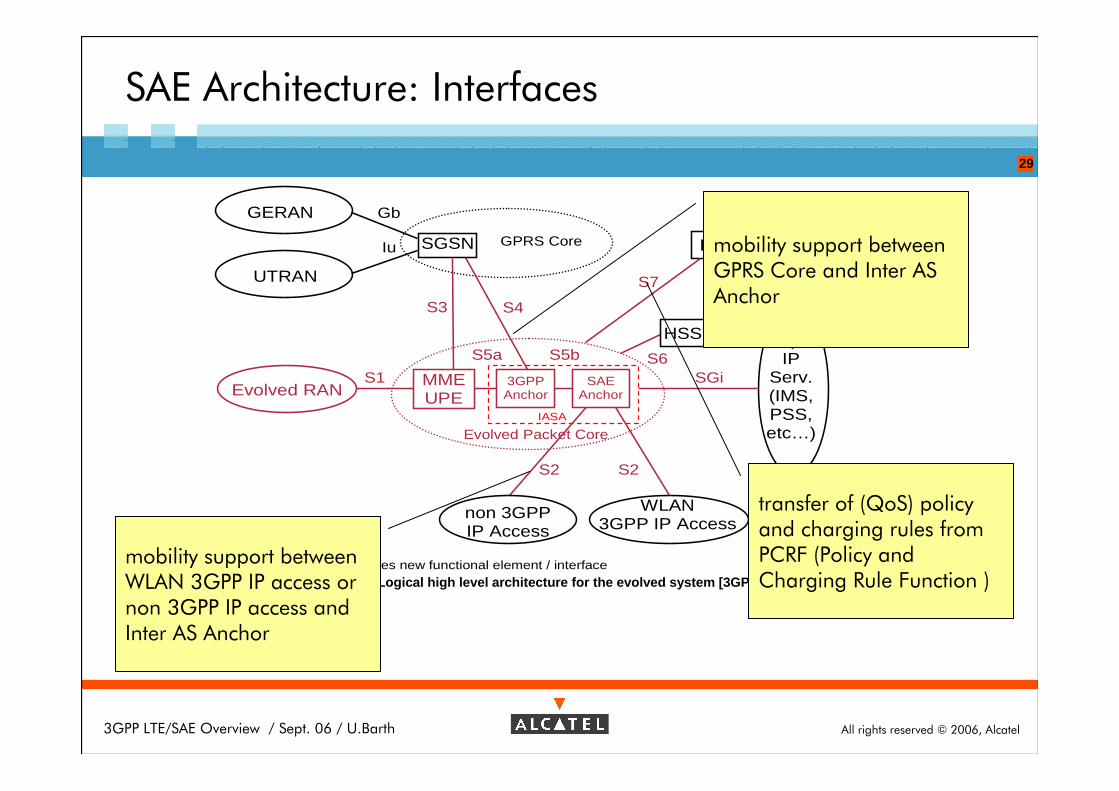
SAE Architecture: Interfaces
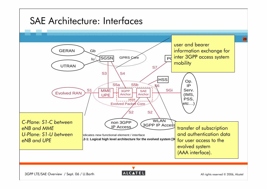
C-Plane: S1-C between eNB and MMEU-Plane: S1-U between eNB and UPE
user and bearer information exchange for inter 3GPP access system mobility
transfer of subscription and authentication data for user access to the evolved system(AAA interface).
All rights reserved © 2006, Alcatel3GPP LTE/SAE Overview / Sept. 06 / U.Barth
29
S5b
Evolved Packet Core
WLAN 3GPP IP Access
S2
non 3GPP IP Access
S2
IASA
S5a
SAE Anchor
3GPP Anchor
S4
SGi Evolved RAN
S1
Op. IP
Serv. (IMS, PSS, etc…)
Rx+
GERAN
UTRAN
Gb
Iu
S3
MME UPE
HSS
PCRF
S7
S6
* Color coding: red indicates new functional element / interface
SGSN GPRS Core
Figure 4.2-1: Logical high level architecture for the evolved system [3GPP TR 23.882]
SAE Architecture: Interfaces
mobility support between WLAN 3GPP IP access or non 3GPP IP access and Inter AS Anchor
mobility support between GPRS Core and Inter AS Anchor
transfer of (QoS) policy and charging rules from PCRF (Policy and Charging Rule Function )


![A Review on Evolution of 3GPP Systems Interworking withWLAN · A Review on Evolution of 3GPP Systems Interworking with WLAN 139 3GPP specification [8], Internet Protocol Security](https://img.pdfslide.net/doc/110x75/5eceba7b692be5115014cbde/a-review-on-evolution-of-3gpp-systems-interworking-withwlan-a-review-on-evolution.jpg)