Embed Size (px)
Citation preview
3GPP TS 23.007 V9.4.0 (2010-06)Technical Specification
3rd Generation Partnership Project;Technical Specification Group Core Network and Terminals;
Restoration procedures(Release 9)
The present document has been developed within the 3rd Generation Partnership Project (3GPP TM) and may be further elaborated for the purposes of 3GPP. The present document has not been subject to any approval process by the 3GPP Organisational Partners and shall not be implemented. This Specification is provided for future development work within 3GPP only. The Organisational Partners accept no liability for any use of this Specification. Specifications and reports for implementation of the 3GPP TM system should be obtained via the 3GPP Organisational Partners' Publications Offices.
3GPP
3GPP TS 23.007 V9.4.0 (2010-06)2Release 9
Keywords GSM, UMTS, network
3GPP
Postal address
3GPP support office address 650 Route des Lucioles - Sophia Antipolis
Valbonne - FRANCE Tel.: +33 4 92 94 42 00 Fax: +33 4 93 65 47 16
Internet http://www.3gpp.org
Copyright Notification
No part may be reproduced except as authorized by written permission. The copyright and the foregoing restriction extend to reproduction in all media.
© 2010, 3GPP Organizational Partners (ARIB, CCSA, ETSI, T1, TTA, TTC).
All rights reserved.
UMTS™ is a Trade Mark of ETSI registered for the benefit of its members 3GPP™ is a Trade Mark of ETSI registered for the benefit of its Members and of the 3GPP Organizational Partners LTE™ is a Trade Mark of ETSI currently being registered for the benefit of its Members and of the 3GPP Organizational Partners GSM® and the GSM logo are registered and owned by the GSM Association
3GPP
3GPP TS 23.007 V9.4.0 (2010-06)3Release 9
Contents Foreword ...................................................................................................................................................... 6 1 Scope .................................................................................................................................................. 7 1.1 References ................................................................................................................................................... 7 1.2 Abbreviations............................................................................................................................................... 8 2 Design objectives................................................................................................................................. 8 3 Restoration indicators in location registers and in GPRS support nodes ................................................ 9 3.1 Restoration Indicators in the VLR ................................................................................................................ 9 3.2 Restoration Indicators in the HLR .............................................................................................................. 10 3.3 Restoration Indicators in the SGSN ............................................................................................................ 10 3.4 Restoration Indicators in the MME ............................................................................................................ 11 4 Restoration of data in the VLR .......................................................................................................... 11 4.0 VLR Failure ............................................................................................................................................... 11 4.1 Restart of the VLR ..................................................................................................................................... 12 4.2 Restoration Procedures ............................................................................................................................... 12 4.2.1 Incoming Call ...................................................................................................................................... 12 4.2.2 Mobile Terminated Short Message ....................................................................................................... 13 4.2.3 Mobile Terminating Location Request (MT-LR) ................................................................................... 14 4.2.4 Incoming LCS Information Request (GSM only) .................................................................................. 14 4.2.5 Outgoing MS request ............................................................................................................................ 15 4.2.6 Outgoing LMU Request (GSM only) .................................................................................................... 15 4.2.7 Location Updating or IMSI Attach ....................................................................................................... 15 4.2.8 Use of TMSI ......................................................................................................................................... 16 4.2.9 SGSN associations ................................................................................................................................ 16 4.2.10 MME associations ................................................................................................................................ 16 5 Restoration of data in the HLR .......................................................................................................... 16 5.1 Restart of the HLR/HSS ............................................................................................................................. 17 5.2 Procedures During Restoration ................................................................................................................... 17 5.2.1 Mobile terminated call .......................................................................................................................... 17 5.2.2 Mobile Originated Activity ................................................................................................................... 17 6 Periodic location updating ................................................................................................................. 18 7 Periodic routeing area updating .......................................................................................................... 18 8 Stand-alone operation of the VLR ...................................................................................................... 18 9 Stand-alone operation of the SGSN.................................................................................................... 18 9A Stand-alone operation of the MME .................................................................................................... 19 10 Restoration of data in the GGSN ....................................................................................................... 19 10.0 GGSN failure ............................................................................................................................................. 19 10.1 Restart of the GGSN .................................................................................................................................. 19 10.2 Restoration Procedures ............................................................................................................................... 19 10.2.1 Mobile terminated transmission ............................................................................................................ 19 10.2.2 Mobile originated transmission ............................................................................................................. 19 11 Restoration of data in the SGSN ........................................................................................................ 19 11.0 SGSN Failure ............................................................................................................................................ 19 11.0.1 Gn/Gp SGSN failure............................................................................................................................. 19 11.0.2 SGSN Failure using S4 ......................................................................................................................... 20 11.1 Restart of the SGSN ................................................................................................................................... 20 11.2 Restoration Procedures ............................................................................................................................... 21 11.2.1 Mobile terminated user data transmission ............................................................................................. 21
3GPP
3GPP TS 23.007 V9.4.0 (2010-06)4Release 9
11.2.2 Mobile terminated services requested by the MSC/VLR ........................................................................ 21 11.2.3 Mobile terminated SMS over GPRS ...................................................................................................... 21 11.2.4 Mobile originated Routeing Area Updating or Attach ........................................................................... 21 11.2.5 Mobile originated LLC frame ............................................................................................................... 22 11.3 Use of TLLI ............................................................................................................................................... 22 11.4 VLR associations ....................................................................................................................................... 22 12 Restoration of Data in an SMLC (GSM only) .................................................................................... 22 12.1 Restart of an SMLC ................................................................................................................................... 22 12.2 Data Restoration for a Specific LMU.......................................................................................................... 23 13 Restoration of Data in an LMU (GSM only) ...................................................................................... 23 14 Restoration of data in the MME ......................................................................................................... 23 14.1 Restart of the MME ................................................................................................................................... 23 14.1.1 Restoration Procedures ......................................................................................................................... 23 14.1.2 Mobile originated Tracking Area Updating or E-UTRAN Attach ......................................................... 23 14.1.3 Mobile terminated services requested by the MSC/VLR ........................................................................ 24 14.2 VLR associations ....................................................................................................................................... 24 14.3 Partial Failure Handling at MME ............................................................................................................... 24 14.3.1 General ................................................................................................................................................ 24 14.3.2 Procedures during PDN Connection Establishment ............................................................................... 24 14.3.3 Procedures during MME Partial Failure ............................................................................................... 24 14.3.4 Procedures during a Peer’s Partial Failure ............................................................................................ 25 14.3.5 Procedures during PDN Connection Removal or Modification .............................................................. 25 15 Restoration of data in GERAN/UTRAN ............................................................................................ 26 15.1 BSS Failure (A/Gb mode) .......................................................................................................................... 26 15.2 RNC/BSC Failure (Iu mode) ...................................................................................................................... 26 15.3 RNC/BSC Failure (Iu mode) using S4 ........................................................................................................ 26 15A Restoration of data in E-UTRAN ....................................................................................................... 26 15A.1 eNodeB Failure .......................................................................................................................................... 26 16 Restoration of data in the SGW ......................................................................................................... 27 16.1 Restart of the SGW .................................................................................................................................... 27 16.1.0 SGW Failure ........................................................................................................................................ 27 16.1.1 Restoration Procedures ......................................................................................................................... 27 16.2 Partial Failure Handling at SGW ............................................................................................................... 27 16.2.1 General ................................................................................................................................................ 27 16.2.2 Procedures during PDN Connection Establishment ............................................................................... 28 16.2.3 Procedures during SGW Partial Failure ................................................................................................ 28 16.2.4 Procedures during a Peer’s Partial Failure ............................................................................................ 28 16.2.5 Procedures during PDN Connection Removal or Modification .............................................................. 29 17 Restoration of data in the PGW ......................................................................................................... 30 17.1 Restart of the PGW .................................................................................................................................... 30 17.1.0 PGW Failure ........................................................................................................................................ 30 17.1.1 Restoration Procedures ......................................................................................................................... 30 17.2 Partial Failure Handling at PGW ............................................................................................................... 31 17.2.1 General ................................................................................................................................................ 31 17.2.2 Procedures during PDN Connection Establishment ............................................................................... 31 17.2.3 Procedures during PGW Partial Failure ................................................................................................ 31 17.2.4 Procedures during a Peer’s Partial Failure ............................................................................................ 31 17.2.5 Procedures during PDN Connection Removal or Modification .............................................................. 32 17A Restoration of data in the MBMS GW ............................................................................................... 32 17A.1 Restart of the MBMS GW .......................................................................................................................... 32
3GPP
3GPP TS 23.007 V9.4.0 (2010-06)5Release 9
18 GTP-C based restart procedures ........................................................................................................ 32 19 PMIPv6 based restart procedures....................................................................................................... 33 20 Path management procedures ............................................................................................................. 33 21 Error Indication handling ................................................................................................................... 34 21.1 General ...................................................................................................................................................... 34 21.2 GGSN ........................................................................................................................................................ 34 21.3 Gn/Gp SGSN ............................................................................................................................................. 34 21.4 S4 SGSN ................................................................................................................................................... 34 21.5 RNC or NodeB........................................................................................................................................... 35 21.6 eNodeB ...................................................................................................................................................... 35 21.7 SGW .......................................................................................................................................................... 35 21.8 PGW .......................................................................................................................................................... 35 21.9 MBMS GW ............................................................................................................................................... 36 22 Downlink Data Notification Handling at MME/S4 SGSN .................................................................. 36 23 General partial failure handling procedures ........................................................................................ 36
Annex A (informative): Change history ............................................................................................ 39
3GPP
3GPP TS 23.007 V9.4.0 (2010-06)6Release 9
Foreword This Technical Specification (TS) has been produced by the 3rd Generation Partnership Project (3GPP).
The present document defines the restoration procedures within the 3GPP system.
The contents of the present document are subject to continuing work within the TSG and may change following formal TSG approval. Should the TSG modify the contents of the present document, it will be re-released by the TSG with an identifying change of release date and an increase in version number as follows:
Version x.y.z
where:
x the first digit:
1 presented to TSG for information;
2 presented to TSG for approval;
3 or greater indicates TSG approved document under change control.
y the second digit is incremented for all changes of substance, i.e. technical enhancements, corrections, updates, etc.
z the third digit is incremented when editorial only changes have been incorporated in the document.
3GPP
3GPP TS 23.007 V9.4.0 (2010-06)7Release 9
1 Scope The data stored in location registers are automatically updated in normal operation; the main information stored in a location register defines the location of each mobile station and the subscriber data required to handle traffic for each mobile subscriber. The loss or corruption of these data will seriously degrade the service offered to mobile subscribers; it is therefore necessary to define procedures to limit the effects of failure of a location register, and to restore the location register data automatically. The present document defines the necessary procedures.
The basic principle is that restoration should be based on radio contact to avoid faulty data being spread in the system.
Subscriber data for supplementary services must also be correctly restored, although the impact on service of corruption of supplementary service data is less severe.
Procedures for supporting these functions are defined in 3GPP TS 29.002 [6] and 3GPP TS 29.060 [8].
The MAP operation "IMSI Attach" is used only in MAP version 1; in MAP version 2 the same function is performed by the MAP operation "Update Location Area". References in this specification to IMSI attach apply only to MAP version 1 network entities.
If the restoration of subscriber data in the VLR is triggered by Location Updating or IMSI Attach, the VLR retrieves subscriber data from the HLR by sending an "Update Location" request, which triggers one or more "Insert Subscriber Data" operations from the HLR. The "Update Location" request may also be used to send the LMSI to the HLR.
If the restoration of subscriber data in the VLR is triggered by a "Provide Roaming Number" request, the behaviour of the VLR depends on whether it is implemented according to MAP version 1 or MAP version 2. For MAP version 2, the VLR retrieves subscriber data from the HLR by sending a "Restore Data" request, which triggers one or more "Insert Subscriber Data" operations from the HLR. The "Restore Data" request is also used to send the LMSI to the HLR. For MAP version 1, the VLR retrieves subscriber data from the HLR by sending a "Send Parameters" request with parameter type "Subscriber Data", which cannot be used to send the LMSI to the HLR.
The VLR number and MSC number in the subscriber data in the HLR are updated by the "Update Location" procedure.
The GGSN (Gateway GPRS Support Node) is the point of PDN interconnection with the GSM PLMN supporting GPRS. The GGSN contains routing information for GPRS users with a PDP context active. The necessary procedures needed to restore GGSN data information after a restart are described in this document.
The SGSN (Serving GPRS Support Node) is the node that is serving the MS. The SGSN stores information regarding e.g. mobility management, routing and security. The necessary procedures needed to restore this SGSN information after a restart are described in this document.
The MME (Mobility Management Entity) is the node that is serving the UE when attached to E-UTRAN. The MME stores information regarding e.g. mobility management, routing and security. The necessary procedures needed to restore this MME information after a restart are described in this document.
A Type A LMU (Location Measurement Unit) is a network node, accessed over the GSM air interface, that is functionally similar to an MS. All requirements associated with a non-GPRS MS in this specification apply also to a Type A LMU except where specified otherwise.
1.1 References The following documents contain provisions which, through reference in this text, constitute provisions of the present document.
References are either specific (identified by date of publication, edition number, version number, etc.) or non-specific.
For a specific reference, subsequent revisions do not apply.

3GPP
3GPP TS 23.007 V9.4.0 (2010-06)8Release 9
For a non-specific reference, the latest version applies. In the case of a reference to a 3GPP document (including a GSM document), a non-specific reference implicitly refers to the latest version of that document in the same Release as the present document.
[1] 3GPP TR 21.905: "Vocabulary of 3GPP Specifications ".
[2] Void
[3] Void
[4] 3GPP TS 23.040: "Technical realisation of SMS Point to Point".
[5] 3GPP TS 23.060: "General Packet Radio Service (GPRS) Service description; Stage 2".
[6] 3GPP TS 29.002: "Mobile Application Part (MAP) specification".
[7] 3GPP TS 29.018:"Serving GPRS Support Node (SGSN) - Visitors Location Register (VLR); Gs interface layer 3 specification".
[8] 3GPP TS 29.060: "GPRS Tunneling Protocol (GTP) across the Gn and Gp Interface".
[9] 3GPP TS 43. 005: "Digital cellular telecommunication system: Technical performance objectives".
[10] 3GPP TS 23.071: "Digital cellular telecommunications system; Location Services (LCS); Functional Description; Stage 2".
[11] Void
[12] 3GPP TS 23.246: "Multimedia Broadcast/Multicast Service (MBMS) Architecture and Functional Description"
[13] 3GPP TS 29.274: " Evolved GPRS Tunnelling Protocol for EPS (GTPv2)"
[14] 3GPP TS 29.118:"Mobility Management Entity (MME) – Visitor Location Register (VLR) SGs interface specification".
[15] 3GPP TS 23.401: "General Packet Radio Service (GPRS) enhancements for Evolved Universal Terrestrial Radio Access Network (E-UTRAN) access"
[16] 3GPP TS 29.275: "Proxy Mobile IPv6 Mobility and Tunneling Protocols"
[17] 3GPP TS 29.281: "GPRS Tunneling Protocol User Plane (GTPv1-U)"
1.2 Abbreviations For the purposes of the present document, the abbreviations listed in 3GPP TR 21. 905 [1] apply.
2 Design objectives To avoid loss of all the data stored in a location register when part of the equipment of the location register fails, a regime must be implemented to secure the data. This regime can include replication of volatile storage units and periodic back-up of data to non-volatile storage. If the data security regime ensures the integrity of the data in spite of failure of part of the location register equipment then there will be no impact on service. This Technical Specification describes the procedures to be used when the integrity of data in the location register cannot be ensured; that situation is referred to below as "failure".
The VLR and SGSN shall erase all IMSI records affected by the failure when it restarts after a failure. The GGSN shall erase all non-static PDP records affected by the failure and restore static PDP records when it restarts after a failure.
3GPP
3GPP TS 23.007 V9.4.0 (2010-06)9Release 9
For the HLR, periodic back-up of data to non-volatile storage is mandatory.
The reliability objectives of location registration are listed in 3GPP TS 43. 005 [9].
The MME, S-GW and P-GW must similarly have a regime to secure the PDN connection and bearer data at failures. When an MME, SGW or PGW has a full node restart or fails all PDN connections and bearer records associated with the failing node shall be erased and any internal resources released.
Clause 18 "GTP-C based restart procedures" specifies how a GTP-C entity restart is detected and handled by the peer.
3 Restoration indicators in location registers and in GPRS support nodes
3.1 Restoration Indicators in the VLR Three restoration indicators are provided in the VLR for each IMSI record: "Confirmed by Radio Contact", "Subscriber Data Confirmed by HLR" and "Location Information Confirmed in HLR".
The indicator "Confirmed by Radio Contact" indicates whether the VLR"s record of location area identity and MSC number for the mobile station is confirmed by radio contact.
The indicator "Confirmed by Radio Contact" in an IMSI record is set to the initial value "Not Confirmed" when the VLR receives a "Provide Roaming Number" request, an "Update Location Area" request or an "IMSI Attach" request for an MS for which the VLR does not have an IMSI record. The indicator "Confirmed by Radio Contact" in an IMSI record may also be set to the initial value "Not Confirmed" when the VLR receives a Reset indication message from the SGSN serving the MS if the MS is attached to both GPRS and non-GPRS services (see 3GPP TS 29.018 [7]) , or a Reset indication message from the MME serving the UE if the UE is attached to both EPS and non-EPS services or for SMS only (see 3GPP TS 29.118 [14]).
The indicator "Confirmed by Radio Contact" is set to "Confirmed" when the radio contact that has been established with the MS is authenticated.
The indicator "Subscriber Data Confirmed by HLR" indicates whether the subscriber data set for the mobile station held by the VLR is consistent with that held by the HLR.
The indicator "Subscriber Data Confirmed by HLR" is set to the initial value "Not Confirmed" when the VLR receives a "Provide Roaming Number" request, an "Update Location Area" request or an "IMSI Attach" request for an MS for which the VLR does not have an IMSI record.
The indicator "Subscriber Data Confirmed by HLR" is set to "Confirmed" at either of the following events:
- The VLR successfully performs an "Update Location" to the HLR;
- The VLR successfully performs a "Restore Data" operation to the HLR.
The indicator "Location Information Confirmed in HLR" indicates whether the HLR"s record of VLR number and MSC number for the mobile station is confirmed by radio contact.
The indicator "Location Information Confirmed in HLR" is set to "Not Confirmed" at any of the following events:
- The VLR receives an "Update Location Area" request or an IMSI Attach" request for an MS for which the VLR has no IMSI record;
- A VLR which serves two or more MSCs receives a "Provide Roaming Number" request for an MS for which the VLR has no IMSI record;
- The VLR receives a "Reset" message from the HLR with which the MS is registered;
- The VLR in a Super-Charged network receives a Send Identification message from the serving VLR;
3GPP
3GPP TS 23.007 V9.4.0 (2010-06)10Release 9
- The VLR in a Super-Charged network receives a Cancel Location message that indicates an "updateProcedure".
The indicator "Location Information Confirmed in HLR" is set to "Confirmed" at either of the following events:
- A VLR which serves only one MSC receives a "Provide Roaming Number" request for an MS for which the VLR has no IMSI record;
- Successful completion of the "Update Location" procedure triggered by authenticated radio contact.
The indicator "Location Information Confirmed in SMLC" indicates whether an SMLC's record of MSC number for a particular LMU is confirmed by radio contact.
The indicator "Location Information Confirmed in SMLC" is set to "Not Confirmed" at any of the following events:
- The VLR receives an "Update Location Area" request or an "IMSI Attach" request for an MS for which the VLR has no IMSI record. The indicator, in this case, becomes valid only if HLR subscriber data later indicates an LMU;
- The VLR receives an "LCS Reset" message from an SMLC where the message is targetted to either a specific LMU or all LMUs registered with the SMLC;
- The VLR receives an "IMSI Detach" from an LMU that is registered with an SMLC.
The indicator "Location Information Confirmed in SMLC" is set to "Confirmed" at the following event:
- Successful completion of the "LCS Registration" procedure triggered by a successful location update;
- Successful transfer of an LCS Information message from an SMLC to the LMU.
3.2 Restoration Indicators in the HLR As an implementation option, one restoration indicator may be provided in the HLR for each IMSI record: "Check SS".
The "Check SS" indicator is set to "Check Required" when the HLR restarts after a failure.
The "Check SS" indicator is checked whenever the HLR receives an "Update Location" request from a VLR. If it is set to "Check Required", after successful completion of subscriber data retrieval that ran embedded in the "Update Location" procedure the HLR sends a "Forward Check SS Indication" request message to the VLR and sets the "Check SS" indicator to "Check Not Required".
3.3 Restoration Indicators in the SGSN Two restoration indicators are provided in the SGSN for reach IMSI record: "Subscriber Data Confirmed by HLR" and "Location Information Confirmed in HLR".
The indicator "Subscriber Data Confirmed by HLR" indicates whether the subscriber data set for the mobile station held by the SGSN is consistent with that held by the HLR.
The indicator "Subscriber Data Confirmed by HLR" is set to the initial value "Not Confirmed" when the SGSN receives a Routing Area Update request or an IMSI- and/or GPRS Attach request for an MS for which the SGSN does not have an IMSI record.
The indicator "Subscriber Data Confirmed by HLR" is set to "Confirmed" at the following event:
- The SGSN successfully performs an Update GPRS Location to the HLR;
The indicator "Location Information Confirmed in HLR" indicates whether the HLRs record of the SGSN address for the mobile station is confirmed by radio contact.
The indicator "Location Information Confirmed in HLR" is set to "Not Confirmed" at any of the following events:
3GPP
3GPP TS 23.007 V9.4.0 (2010-06)11Release 9
- The SGSN receives a Routing Area Update request or an IMSI- and/or GPRS Attach request for an MS for which the SGSN has no IMSI record;
- The SGSN receives a "Reset" message from the HLR with which the MS is registered;
- The SGSN in a Super-Charged network receives a Send Identification message from the serving SGSN;
- The SGSN in a Super-Charged network receives a Cancel Location message that indicates an "updateProcedure".
The indicator "Location Information Confirmed in HLR" is set to "Confirmed" at the following event:
- Successful completion of the Update GPRS Location procedure to the HLR.
The indicator "VLR-Reliable" indicates whether the VLR serving the MS has performed a restart.
The indicator "VLR-Reliable" is set to the value "false" when the SGSN receives a Reset indication message from the VLR serving the MS if the MS is attached to both GPRS and non-GPRS services. The indicator "VLR-Reliable" is set to the value "true" when the SGSN receives a confirmation from a VLR that a location update procedure to the affected VLR has been successfully performed.
The indicator "SGSN-Reset" indicates whether the SGSN has recently experienced a restart.
The indicator "SGSN-Reset" is set to the value "true" when the SGSN suffers a restart. This indicator is unique per SGSN. The indicator "SGSN-Reset" is set to the value "false" after a certain time specified by the operator. The value of the timer controlling the reset of the "SGSN-Reset" indicator shall be longer than the periodic routeing area update timer value used by the MSs.
3.4 Restoration Indicators in the MME Two restoration indicators are provided in the MME for each IMSI record: "Subscriber Data Confirmed by HSS" and "Location Information Confirmed in HSS".
The indicator "Subscriber Data Confirmed by HSS" indicates whether the subscriber data set for the mobile station held by the MME is consistent with that held by the HSS.
The indicator "Subscriber Data Confirmed by HSS" shall be set to the initial value "Not Confirmed" when the MME receives a Tracking Area Update request or an Attach request for an UE for which the MME does not have an IMSI record.
The indicator "Subscriber Data Confirmed by HSS" shall be set to "Confirmed" at the following event:
- The MME successfully performs an Update Location to the HSS;
The indicator "Location Information Confirmed in HSS" indicates whether the HSS’s record of the MME address for the UE is confirmed by radio contact.
The indicator "Location Information Confirmed in HSS" shall be set to "Not Confirmed" at any of the following events:
- The MME receives a Tracking Area Update request or an Attach request for an UE for which the MME has no IMSI record;
- The MME receives a "Reset" message from the HSS with which the UE is registered;
The indicator "Location Information Confirmed in HSS" shall be set to "Confirmed" at the following event:
- Successful completion of the Update Location procedure to the HSS.
3GPP
3GPP TS 23.007 V9.4.0 (2010-06)12Release 9
4 Restoration of data in the VLR The effect on service of failure of a VLR is different from the effect of failure of an HLR. The procedures for restoration of a VLR and an HLR are therefore different.
4.0 VLR Failure When a VLR fails, all its associations with SGSNs affected by the failure become invalid and may be deleted. Based on configuration data, the MSC/VLR sends a BSSAP+ Reset message to each of its associated SGSNs. The SGSNs mark all associations containing the restarted VLR as invalid. After receipt of the first valid LLC frame (for A/Gb mode) or after receipt of the first valid GTP-U packet or uplink signalling message (for Iu mode) from an MS that is both GPRS-attached and IMSI-attached, the SGSN shall return a Detach Request (Detach Type) message in order to request the MS to perform a combined RA / LA update. Detach Type shall be set to IMSI Detach. The detach procedure may be delayed by the SGSN for a maximum operator-configuration depending on resource utilisation during given time period to avoid high signalling load.
4.1 Restart of the VLR When a VLR restarts after a failure, all IMSI records affected by the failure are erased.
There will be no subscriber data or location information stored for an affected mobile station until after the VLR has received either a "Provide Roaming Number" request or an "Update location Area" request for that mobile station.
The VLR causes all affected TMSIs and all affected LMSIs to become invalid. "Invalid" in this context means that the TMSI and LMSI can no longer be regarded as accurate. The term is used to avoid unnecessary constraints on the implementation.
On receipt of either a "Provide Roaming Number" request or an "Update Location Area" request, restoration of subscriber data in the VLR is triggered individually for each IMSI record as described below.
4.2 Restoration Procedures The objective of the restoration procedure is to handle all traffic for each mobile subscriber correctly. In order to meet this objective, the procedure must make the subscriber data in the VLR consistent with that in the HLR, and make the location information in the HLR and VLR reflect accurately the current location of the MS.
4.2.1 Incoming Call a) Send Routing Information (GMSC->HLR):
The HLR sends "Provide Roaming Number" to the VLR as for normal operation. The LMSI is updated by the VLR when the VLR requests the transfer of subscriber data from the HLR using the "Restore Data" operation.
b) Provide Roaming Number (HLR->VLR):
- Regardless of whether the VLR has an IMSI record corresponding to the IMSI in the "Provide Roaming Number", it returns an MSRN. If no IMSI record exists, the VLR creates a skeleton IMSI record, sets the indicators "Subscriber Data Confirmed by Radio Contact" and "Confirmed by HLR" to "Not Confirmed" and (if IMSI Attach is used) marks the IMSI as attached. If the VLR serves two or more MSCs, the VLR sets the indicator "Location Information Confirmed in HLR" to "Not Confirmed". Otherwise, if the VLR serves only one MSC, the indicator "Location Information Confirmed in HLR" is set to the initial value "Confirmed".
- If the indicator "Subscriber Data Confirmed by HLR" is "Not Confirmed" the VLR requests authentication data, if required and still not available and subscriber data from the HLR. When the dialogue that covers the subscriber data retrieval procedure is completed successfully, the VLR sets the indicator "Subscriber Data
3GPP
3GPP TS 23.007 V9.4.0 (2010-06)13Release 9
Confirmed by HLR" to "Confirmed". The indicators "Confirmed by Radio Contact" and "Location Information Confirmed in HLR" remain unchanged.
- If the IMSI record for the MS is marked "Subscriber Data Confirmed by HLR" but "Not Confirmed by Radio Contact" the operator may choose an appropriate method to limit the number of "Search for MS" procedures for that MS.
- Ic) Send Information for I/C Call Setup (MSC->VLR)
- If the VLR has no IMSI record, or if the record is marked "Subscriber Data Not Confirmed by HLR" the VLR returns a "System Failure" error.
- If the VLR has an IMSI record marked "Subscriber Data Confirmed by HLR" and "Not Confirmed by Radio Contact", the VLR handles the request in the normal way, except that the "Search for MS" procedure is used instead of the "Page MS" procedure.
- If the VLR has an IMSI record marked "Subscriber Data Confirmed by HLR" and "Confirmed by Radio Contact", the VLR handles the request in the normal way; for this MS, VLR restoration is complete.
- The state of the indicator "Location Information Confirmed in HLR" does not affect the "Send Information for I/C Call Setup" procedure.
d) Process Access Request in Response to Search (MSC->VLR):
- If the MS responds to paging, the MSC sends a positive response to the search request and a "Process Access Request" to the VLR. After successful authentication, if required, the VLR sets the indicator "Confirmed by Radio Contact" to "Confirmed", sets the location area information for the MS, and handles the request in the normal way.
- The VLR checks the indicator "Location Information Confirmed in HLR". If it indicates "Not Confirmed" the VLR starts an "Update Location" procedure to the HLR. When this procedure is successfully completed the VLR sets the indicator "Location Information Confirmed in HLR" to "Confirmed".
For this MS, VLR restoration is complete.
4.2.2 Mobile Terminated Short Message a) Send Routing Information for MT SMS (SMS-GMSC->HLR):
The HLR returns the MSC number as for normal operation.
b) Send Information for MT SMS (MSC->VLR) - MAP version 2:
- If the VLR has no IMSI record, or if the record is marked "Subscriber Data Not Confirmed by HLR" the VLR returns an "Unidentified Subscriber" error. This causes the MSC to report a short message delivery failure, with cause "Unidentified Subscriber", to the SMS gateway MSC. The Gateway MSC sends a "Report SM Delivery Status" request, with a cause of "Absent Subscriber", to the HLR. This causes the HLR to set the "Mobile Station Not Reachable Flag" for the MS, as described in Technical Specifications 3GPP TS 23.040 [4] and 3GPP TS 29.002 [6].
- If the VLR has an IMSI record marked "Subscriber Data Confirmed by HLR" and "Not Confirmed by Radio Contact", the VLR handles the request in the normal way, except that the "Search for MS" procedure is used instead of the "Page MS" procedure.
- If the VLR has an IMSI record marked "Subscriber Data Confirmed by HLR" and "Confirmed by Radio Contact", the VLR handles the request in the normal way; for this MS, VLR restoration is complete.
- The state of the indicator "Location Information Confirmed in HLR" does not affect the "Send Information for MT SMS" procedure.
c) Send Information for I/C Call Setup (MSC->VLR) - MAP version 1:
3GPP
3GPP TS 23.007 V9.4.0 (2010-06)14Release 9
- If the VLR has no IMSI record, or if the record is marked "Subscriber Data Not Confirmed by HLR" the VLR returns a "System Failure" error. This causes the MSC to report a short message delivery failure, with cause "System Failure", to the SMS gateway MSC.
- If the VLR has an IMSI record marked "Subscriber Data Confirmed by HLR" and "Not Confirmed by Radio Contact", the VLR handles the request in the normal way, except that the "Search for MS" procedure is used instead of the "Page MS" procedure.
- If the VLR has an IMSI record marked "Subscriber Data Confirmed by HLR" and "Confirmed by Radio Contact", the VLR handles the request in the normal way; for this MS, VLR restoration is complete.
- The state of the indicator "Location Information Confirmed in HLR" does not affect the "Send Information for MT SMS" procedure.
d) Process Access Request in Response to Search (MSC->VLR):
- If the MS responds to paging, the MSC sends a positive response to the search request and a "Process Access Request" to the VLR. After successful authentication, if required, the VLR sets the indicator "Confirmed by Radio Contact" to "Confirmed", sets the location area information for the MS, and handles the request in the normal way.
- The VLR checks the indicator "Location Information Confirmed in HLR". If it indicates "Not Confirmed" the VLR starts an "Update Location" procedure to the HLR. When this procedure is successfully completed, the VLR sets the indicator "Location Information Confirmed in HLR" to "Confirmed".
For this MS, VLR restoration is complete.
4.2.3 Mobile Terminating Location Request (MT-LR) Receipt of an MT-LR for a target MS identified by its IMSI in a serving MSC during VLR restoration is supported by the procedures below.
a) Provide Subscriber Location (GMLC->MSC/VLR):
- If the VLR has no IMSI record, or if the record is marked "Subscriber Data Not Confirmed by HLR" the VLR returns an "Unidentified Subscriber" error. This causes the MSC to report a location failure, with cause "Unidentified Subscriber", to the GMLC.
- If the VLR has an IMSI record marked "Subscriber Data Confirmed by HLR" and "Not Confirmed by Radio Contact", the VLR handles the request in the normal way, except that the "Search for MS" procedure is used instead of the "Page MS" procedure when paging for the MS.
- If the VLR has an IMSI record marked "Subscriber Data Confirmed by HLR" and "Confirmed by Radio Contact", the VLR handles the request in the normal way; for this MS, VLR restoration is complete.
- The state of the indicator "Location Information Confirmed in HLR" does not affect the "Provide Subscriber Location" procedure.
b) Process Access Request in Response to Search (MSC->VLR):
- If the MS responds to paging, the MSC sends a positive response to the search request and a "Process Access Request" to the VLR. After successful authentication, if required, the VLR sets the indicator "Confirmed by Radio Contact" to "Confirmed", sets the location area information for the MS, and handles the request in the normal way.
- The VLR checks the indicator "Location Information Confirmed in HLR". If it indicates "Not Confirmed" the VLR starts an "Update Location" procedure to the HLR. When this procedure is successfully completed, the VLR sets the indicator "Location Information Confirmed in HLR" to "Confirmed".
For this MS, VLR restoration is complete.
3GPP
3GPP TS 23.007 V9.4.0 (2010-06)15Release 9
4.2.4 Incoming LCS Information Request (GSM only) Receipt of an incoming BSSMAP-LE LMU Connection Request from an SMLC directed to a specific Type A LMU is supported by the procedures below.
a) Request associated with an LMU (SMLC->MSC/VLR):
- If the VLR has no IMSI record, or if the record is marked "Subscriber Data Not Confirmed by HLR", the VLR returns an "Unidentified Subscriber" error.
- If the VLR has an IMSI record for an LMU marked "Subscriber Data Confirmed by HLR" and "Not Confirmed by Radio Contact", the VLR handles the request in the normal way, except that the "Search for MS" procedure is used instead of the "Page MS" procedure when paging for the LMU.
- If the VLR has an IMSI record marked "Subscriber Data Confirmed by HLR" and "Confirmed by Radio Contact", the VLR handles the request in the normal way. For this LMU, data restoration is complete.
- The state of the indicator "Location Information Confirmed in HLR" does not affect the incoming LMU Connection Request.
b) Process Access Request in Response to Search (MSC->VLR):
- If the LMU responds to paging, the MSC sends a positive response to the search request and a "Process Access Request" to the VLR. After successful authentication, if required, the VLR sets the indicator "Confirmed by Radio Contact" to "Confirmed", sets the location area information for the LMU, and handles the request in the normal way.
- The VLR checks the indicator "Location Information Confirmed in HLR". If it indicates "Not Confirmed" the VLR starts an "Update Location" procedure to the HLR. When this procedure is successfully completed, the VLR sets the indicator "Location Information Confirmed in HLR" to "Confirmed".
For this LMU, VLR restoration is complete.
4.2.5 Outgoing MS request An outgoing request (MS originated call, mobile originated Short Message or call-independent supplementary service activity) from the MS causes the VLR to check its IMSI record for that MS.
- If the MS is unknown in this VLR (i.e. the VLR has no IMSI record for the MS) or there is an IMSI record marked "Subscriber Data Not Confirmed by HLR" the outgoing request is rejected with error cause "Unidentified Subscriber". This causes the MS to initiate the location registration procedure described below.
- If the VLR has an IMSI record for the MS marked "Subscriber Data Confirmed by HLR" the request is handled in the normal way, and after any necessary authentication and/or IMEI checking the record is marked "Confirmed by Radio Contact".
- The VLR checks the indicator "Location Information Confirmed in HLR". If it indicates "Not Confirmed" the VLR starts an "Update Location" procedure to the HLR. When this procedure is successfully completed the VLR sets the indicator "Location Information Confirmed in HLR" to "Confirmed".
For this MS, VLR restoration is complete.
4.2.6 Outgoing LMU Request (GSM only) An outgoing request (CM ServiceRequest) for LCS from a Type A LMU causes the VLR to check its IMSI record for that LMU.
- If the LMU is unknown in this VLR (i.e. the VLR has no IMSI record for the LMU) or there is an IMSI record marked "Subscriber Data Not Confirmed by HLR" the outgoing request is rejected with error cause "Unidentified Subscriber". This causes the LMU to initiate the location registration procedure described below.
3GPP
3GPP TS 23.007 V9.4.0 (2010-06)16Release 9
- If the VLR has an IMSI record for the MS marked "Subscriber Data Confirmed by HLR", the request is handled in the normal way, and after any necessary authentication and/or IMEI checking the record is marked "Confirmed by Radio Contact".
- The VLR checks the indicator "Location Information Confirmed in HLR". If it indicates "Not Confirmed" the VLR starts an "Update Location" procedure to the HLR. When this procedure is successfully completed the VLR sets the indicator "Location Information Confirmed in HLR" to "Confirmed".
For this LMU, VLR restoration is complete.
4.2.7 Location Updating or IMSI Attach A location registration request (location updating or IMSI attach) from an MS causes the VLR to check its IMSI record for that MS.
- If the MS is unknown in this VLR (i.e. the VLR has no IMSI record for the MS) the VLR creates a skeleton IMSI record for the MS and sets the indicators "Confirmed by Radio Contact", "Location Information Confirmed in HLR" and "Subscriber Data Confirmed by HLR" to "Not Confirmed". If authentication is required, the VLR retrieves authentication data. When the radio contact with the Mobile Station is authenticated, the VLR sets the indicator "Confirmed by Radio Contact" to "Confirmed. The VLR then performs an "Update Location" to the HLR. If this is successful, the VLR sets the indicators "Location Information Confirmed in HLR" and "Subscriber Data Confirmed by HLR" to "Confirmed". For this MS, VLR restoration is complete.
- If the VLR has an IMSI record for the MS, after successful authentication, if required, the VLR sets the indicator "Confirmed by Radio Contact" to "Confirmed". If the record is marked "Location Information Not Confirmed in HLR" or "Subscriber Data Not Confirmed by HLR" the VLR performs an "Update Location" to the HLR. If this is successful, the VLR sets the indicators "Location Information Confirmed in HLR" and "Subscriber Data Confirmed by HLR" to "Confirmed". For this MS, VLR restoration is complete.
4.2.8 Use of TMSI After the VLR has restarted but before the next authenticated radio contact the TMSI known by the MS is invalid, as it was allocated before the VLR restarted. The VLR therefore uses the IMSI to identify the MS on the first radio contact during restoration.
- A VLR which initiates a "Search for Subscriber" procedure uses the IMSI to identify the MS.
- If an MS identifies itself by a TMSI in a "Location Registration" request, the VLR proceeds as follows:
a) The VLR checks the location area identity (LAI) of the previous location area sent by the MS. If this LAI is in a VLR different from the current one, the request is handled in the normal way.
b) If the LAI is in the current VLR, the status of the TMSI is checked:
- If the TMSI was allocated after the VLR restarted, and corresponds to a valid IMSI record, the request is handled as described in subclause 4.2.7.
- If the TMSI was allocated before the VLR restarted, or does not correspond to a valid IMSI record, the VLR requests the IMSI from the MS. If the MS returns an IMSI the VLR proceeds as described in subclause 4.2.7. If the MS does not return an IMSI the network aborts the location registration procedure.
- If an MS identifies itself by a TMSI in an outgoing MS request, the VLR proceeds as follows:
- If the TMSI was allocated after the VLR restarted, and corresponds to a valid IMSI record, the request is handled as described in subclause 4.2.5.
- If the TMSI was allocated before the VLR restarted, or does not correspond to a valid IMSI record, the VLR requests the IMSI from the MS. If the MS returns an IMSI the VLR proceeds as described in subclause 4.2.5. If the MS does not return an IMSI the network aborts the outgoing request.
3GPP
3GPP TS 23.007 V9.4.0 (2010-06)17Release 9
4.2.9 SGSN associations Based on configuration data, "Reset" messages are sent on the Gs-interface to the SGSNs in the Location Areas served by the VLR as described in the 3GPP TS 29.018 [7]. The SGSNs mark all associations with the VLR as unreliable by setting the restoration indicator "VLR-Reliable" to "False" for the UEs served by that VLR. The associations will be re-initiated one by one by the SGSN at the next Routing Area update or combined RA/LA update from each UE.
4.2.10 MME associations Based on configuration data, "Reset" messages are sent on the SGs-interface to the MMEs by the VLR as described in the 3GPP TS 29.118 [14]. The MMEs mark all associations with the VLR as unreliable by setting the restoration indicator "VLR-Reliable" to "False" for the UEs served by that VLR. The associations will be re-initiated one by one by the MME at the next Tracking Area update or combined TA/LA update from each UE.
5 Restoration of data in the HLR The loss or corruption of subscriber data in the HLR has an impact not only in the HLR"s own PLMN but also on the service for its mobiles in other PLMNs. Restoration of the data in the HLR requires co-operation from all the VLRs to which its mobiles have roamed.
5.1 Restart of the HLR/HSS When an HLR restarts, it sends to each SGSN where one or more of its MSs are registered a Reset message. This causes the SGSN to mark the relevant MM contexts as invalid, and to set NGAF if an SGSN – MSC/VLR association exists. After receipt of the first valid LLC frame (for A/Gb mode) or after receipt of the first valid GTP-U packet or uplink signalling message (for Iu mode) from a marked MS, the SGSN performs an update location to the HLR as in the attach or inter-SGSN RA update procedures, and, if NGAF is set, the procedure in clause "Non-GPRS Alert" is followed. The update location procedure and the procedure towards the MSC/VLR may be delayed by the SGSN for a maximum operator configuration-depending on the utilisation of resources during given time period to avoid high signalling load. The periodic backup of HLR data to non-volatile storage is mandatory.
When an HLR restarts after failure it shall perform the following actions for the subscriber data records that have been affected by the HLR fault:
- reload all data from the non-volatile back-up;
- reset all "MS Purged" flags;
- mark each subscriber record "SS Check Required" by setting the "Check SS" indicator if the "Forward Check SS Indication" service is implemented;
- send a "Reset" message to each VLR where one or more of its MSs are registered. This causes each VLR concerned to mark each relevant subscriber record "Location Information Not Confirmed in HLR", and
- send a "Reset" message to each SGSN where one or more of its MSs are registered. This causes each SGSN to mark each relevant MM context "Location Information Not Confirmed in HLR".
- send a "Reset" message to each MME where one or more of its UEs are registered. This causes each MME to mark each relevant MM context "Location Information Not Confirmed in HSS".
3GPP
3GPP TS 23.007 V9.4.0 (2010-06)18Release 9
5.2 Procedures During Restoration
5.2.1 Mobile terminated call If the VLR receives a "Process Access Request" request in response to a "Page" or "Search for MS" operation, after successful authentication, if required, it checks the indicator "Location Information Confirmed in HLR". If this indicates "Not Confirmed" the VLR triggers an "Update Location" to the HLR as described in subclause 4.2.1.d).
When the HLR receives the "Update Location" request it stores the VLR number, MSC number and LMSI in the subscriber record as for normal operation.
If the "Forward Check SS Indication" service is implemented, the HLR checks the indicator "Check SS". If this indicates "Check Required", after successful completion of the subscriber data retrieval procedure that ran embedded in the "Update Location" procedure the HLR sends a "Forward Check SS Indication" to the VLR and marks the subscriber record "Check Not Required. When the VLR receives the "Forward Check SS Indication" request it forwards an indication to the MS to alert the user that supplementary service parameters should be checked.
5.2.2 Mobile Originated Activity When the VLR receives a request from an MS (MS originated call, mobile originated Short Message, call-independent supplementary service activity or location registration request) whose IMSI record is marked "Location Information Not Confirmed in HLR", it will perform an "Update Location" to the HLR as described in subclauses 4.2.5 and 4.2.7 above.
When the HLR receives an "Update Location" request from the VLR, it proceeds as described in subclause 5.2.1.
6 Periodic location updating The time taken to confirm the location of an MS after location register failure is governed by the frequency with which the MS establishes radio contact with the network. The location information for an MS which remains silent for a long time will remain doubtful for a long time.
A method of reducing this time is to require the MS to establish radio contact with the network at intervals, purely to confirm its location, if the MS does not move to a new location area (which would lead to a normal location registration) or respond to paging for a mobile terminated call or request a mobile originated call or call-independent supplementary service activity.
The interval between successive periodic location updatings is controlled by a timer in the MS; this timer is reset to its initial value at the end of each successfully established radio contact between the MS and the network.
The use of the periodic location update timer is described in 3GPP TS 43.022.
7 Periodic routeing area updating
All GPRS-attached MSs, except MSs in class-B mode of operation engaged in CS communication, shall perform periodic RA updates. For MSs that are both IMSI-attached and GPRS-attached, the periodic updates depend on whether the Gs interface is installed or not:
- If the Gs interface is installed, periodic RA updates shall be performed, and periodic LA updates shall not be performed. If the SGSN has the indicator "VLR-reliable" set to ´false´ the SGSN shall perform a location area update procedure towards the VLR
- If the Gs interface is not installed, both periodic RA updates and periodic LA updates shall be performed independently. RA updates are performed via the Gb interface, and LA updates are performed via the A interface.
The periodic routeing area update is described in 3GPP TS 23.060.
3GPP
3GPP TS 23.007 V9.4.0 (2010-06)19Release 9
8 Stand-alone operation of the VLR In a 2G authentication regime, triplets, regardless of its nature (generated in a 2G AuC or derived from quintuplets in a 3G VLR or a 3G HLR), may be reused when no unused authentication triplets are available in the VLR for an IMSI record. It is an operator option to define how many times an authentication triplet may be reused in the VLR.
In a 3G authentication regime, quintuplets, regardless of its nature (generated in a 3G AuC or derived from triplets in a 3G VLR), shall not be reused when no unused authentication quintuplets are available in the VLR for an IMSI record.
If the Update Location response contains an error different from "Unknown Subscriber" or "Roaming Not Allowed" or if there is a parameter problem (e.g. no HLR number included), no error shall be indicated to the MSC and the IMSI record in the VLR shall not be affected, provided that the associated "Subscriber Data Confirmed by HLR" indicator is in the "Confirmed" status.
9 Stand-alone operation of the SGSN In a 2G authentication regime, triplets, regardless of their nature (generated in a 2G AuC or derived from quintuplets in a 3G SGSN or a 3G HLR), may be reused when no unused authentication triplets are available in the SGSN for an IMSI record. It is an operator option to define how many times an authentication triplet may be reused in the SGSN.
In a 3G authentication regime, quintuplets, regardless of their nature (generated in a 3G AuC or derived from triplets in a 3G SGSN), shall not be reused when no unused authentication quintuplets are available in the SGSN for an IMSI record.
9A Stand-alone operation of the MME In a E-UTRAN authentication regime, EPS authentication vectors shall not be reused when no unused EPS authentication vectors are available in the MME for an IMSI record.
10 Restoration of data in the GGSN
10.0 GGSN failure When a GGSN fails, all its PDP contexts affected by the failure become invalid and may be deleted. GGSN storage of subscriber data is volatile.
When the GGSN receives a GTP-U PDU for which no PDP context exists, it shall discard the GTP-U PDU and return a a GTP error indication to the originating node (the SGSN or, if Direct Tunnel is established, the RNC).
The GGSN should ensure as far as possible that previously used TEID values are not immediately reused after a GGSN restart, in order to avoid inconsistent TEID allocation throughout the network.
10.1 Restart of the GGSN After a GGSN restart, all the PDP contexts, the MBMS UE contexts, and the MBMS Bearer contexts stored in the GGSN and affected by the restart become invalid and may be deleted.
When the SGSN detects a restart in a GGSN (see clause 18 "GTP-C based restart procedures") with which it has one or more PDP contexts activated, it shall deactivate all these PDP contexts and request the MS to reactivate them. When the SGSN detects a restart in a GGSN with which it has MBMS Bearer context(s) and/or MBMS UE context(s), it shall delete all these MBMS Bearer context(s) and/or MBMS UE context(s).
3GPP
3GPP TS 23.007 V9.4.0 (2010-06)20Release 9
10.2 Restoration Procedures
10.2.1 Mobile terminated transmission When the GGSN receives a mobile terminated PDU for which no valid PDP context exists the GGSN discards the received PDU and may also return an appropriate Error message depending on the protocol used. No further actions are performed by the GGSN. Alternatively, if the GGSN has static PDP information about the PDP address, the GGSN may try to deliver the PDU by initiating the Network-Requested PDP Context Activation procedure (see 3GPP TS 23.060).
10.2.2 Mobile originated transmission When the GGSN receives a tunnel PDU for which no PDP context exists it discards the tunnel PDU and sends an Error indication message to the originating SGSN. The SGSN deactivates the PDP context and sends an Error indication to the MS. The MS may then re-activate the PDP context.
11 Restoration of data in the SGSN
11.0 SGSN Failure
11.0.1 Gn/Gp SGSN failure When an SGSN fails, it deletes all MM and PDP contexts affected by the failure. SGSN storage of subscriber data is volatile. Based on configuration data, the SGSN may send a Reset message to each of its associated VLRs. If a Reset message is sent, the VLR may mark all associations containing the restarted SGSN as unreliable. See 3GPP TS 29.018 [7]. In the case of optional CAMEL interaction the failing SGSN shall invoke the CAMEL-GPRS-Exception procedure towards the GSM-SCFs.
If data or signalling, except GPRS attach and RA update, is received in an SGSN from an MS for which no MM context exists in the SGSN, the SGSN shall discard the data or signalling.
If an RA update request is received in an SGSN from an MS for which no MM context exists in the SGSN, or in the old SGSN for the inter-SGSN RA update case, the SGSN shall reject the RA update with an appropriate cause. In order to remain GPRS-attached, the MS shall then perform a new GPRS attach and should (re-)activate PDP contexts.
If a service request is received in a 3G-SGSN from an MS for which no MM context exists in the 3G-SGSN, the 3G-SGSN shall reject the service request with an appropriate cause. In order to remain GPRS-attached, the MS shall then perform a new GPRS attach and should (re-) activate PDP contexts.
NOTE: In some cases, user interaction may be required, and then the MS cannot (re-)activate the PDP contexts automatically.
When the SGSN receives a PDU Notification Request message for which no MM context exists, the SGSN returns a PDU Notification Response message to the GGSN with an appropriate cause (see clause "Unsuccessful Network-Requested PDP Context Activation Procedure" in 3GPP TS 23.060 [5]), and the SGSN may search the MS by paging with the IMSI in the SGSN area. An MS that is paged for PS services with IMSI as the identifier shall perform a new GPRS attach and should (re-)activate PDP contexts.
When the SGSN receives a GTP-U PDU from the GGSN for which no PDP context exists, it shall discard the GTP-U PDU and send a GTP error indication to the originating GGSN.
When the SGSN receives a GTP-U PDU from the RNC for which no PDP context exists, the SGSN shall discard the GTP-U PDU and send a GTP error indication to the originating RNC.
When the SGSN receives a mobile-terminated SM from the SMS-GMSC for an IMSI unknown in the SGSN, it rejects the request.
3GPP
3GPP TS 23.007 V9.4.0 (2010-06)21Release 9
When the SGSN receives a paging request over the Gs interface for an IMSI unknown in the SGSN and the SGSN has not completed recovery, the SGSN may page the MS for packet services with IMSI as identifier in the area specified by the location information provided by the MSC/VLR. If no such location information is provided, the SGSN may page the MS in the routeing areas corresponding to that MSC/VLR. After the MS performs a combined GPRS attach, the SGSN may continue serving the Gs interface paging request.
11.0.2 SGSN Failure using S4 When the SGSN receives a Downlink Data Notification Request message for which no MM context exists, the SGSN returns a Downlink Data Notification Response message to the Serving GW with an appropriate cause. The Serving GW shall delete the related Bearer context towards SGSN; and if there is no ISR associated MME recorded on the related Bearer context the Serving GW shall also notify the PDN GW to delete the Bearer context.
When the SGSN receives a GTP-U PDU from the Serving GW for which no Bearer context exists, it shall discard the GTP-U PDU and send a GTP error indication to the originating Serving GW.
When the SGSN receives a GTP-U PDU from the MBMS GW for which no MBMS Point to Point Bearer context exists, it shall discard the GTP-U PDU and send a GTP Error Indication to the originating MBMS GW.
11.1 Restart of the SGSN After an SGSN restart, the SGSN deletes all MM, PDP, MBMS UE, and MBMS Bearer contexts affected by the restart.
When the GGSN detects a restart in an SGSN (see clause 18 "GTP-C based restart procedures") with which it has PDP context(s) activated and/or MBMS UE context(s), it shall delete all these PDP context(s) and/or MBMS UE context(s). When the GGSN detects a restart in an SGSN with which it has any MBMS Bearer context, it shall not delete the MBMS bearer context unless all SGSNs connected to the GGSN restart.
When the MBMS GW detects a restart in an SGSN (see clause 18 "GTP-C based restart procedures") with which it has any MBMS Bearer context, it shall not delete the MBMS Bearer context unless all SGSNs/MMEs connected to the MBMS GW restart.
11.2 Restoration Procedures
11.2.1 Mobile terminated user data transmission When the SGSN receives a tunnel PDU for which no PDP context or MBMS Bearer Context exists it discards the tunnel PDU and sends an Error indication message to the originating GGSN.
11.2.2 Mobile terminated services requested by the MSC/VLR When the SGSN receives a request for CS paging from an MSC/VLR for an IMSI unknown by the SGSN, if the "SGSN-Reset" indicator is set to "true", the SGSN sends the paging request with the location information provided by the VLR. If no such location information is provided, the SGSN should page for the MS in all the routeing areas corresponding to that SGSN.
If the "SGSN-Reset" indicator is set to "false" and the IMSI is unknown or the MS is marked as GPRS or non-GPRS detached by the SGSN, the paging request is rejected.
If the "SGSN-Reset" indicator is set to "false" and the IMSI is known and the MS is marked as GPRS and is non-GPRS attached by the SGSN, the paging request shall be sent to the MS.
11.2.3 Mobile terminated SMS over GPRS a) Send Routing Information for MT SMS (SMS-GMSC -> HLR):
3GPP
3GPP TS 23.007 V9.4.0 (2010-06)22Release 9
The HLR returns the SGSN number as for normal operation.
b) Send Information for MT SMS:
- When the SGSN receives a mobile terminated SMS for an unknown MM context for the MS, or if the SGSN indicator "Subscriber Data Confirmed by HLR" is marked "Not Confirmed" it rejects the SMS request and returns a failure report with cause value "Unidentified Subscriber" to the SMS gateway MSC indicating unsuccessful delivery of the SMS. The Gateway MSC sends a "Report SM Delivery Status" request, with a cause of "Absent Subscriber", to the HLR. This causes the HLR to set the "Mobile Station Not Reachable for GPRS Flag" for the MS, as described in the Technical Specifications3GPP TS 23.040 and 3GPP TS 29.002.
- If the SGSN has the indicator "Subscriber Data Confirmed by HLR" set to "Confirmed", the SGSN handles the SMS request in the normal way.
The state of the indicator "Location Information Confirmed in HLR" does not affect the Mobile Terminated SMS procedure.
11.2.4 Mobile originated Routeing Area Updating or Attach For attach, where the MS is unknown in the SGSN (i.e. the SGSN has no MM context for the MS) the SGSN creates an MM context for the MS and sets the indicators "Location Information Confirmed in HLR" and "Subscriber Data Confirmed by HLR" to "Not Confirmed". If authentication is required, the SGSN retrieves authentication data. The SGSN then performs an "Update GPRS Location" to the HLR. If this is successful, the SGSN sets the indicators "Location Information Confirmed in HLR" and "Subscriber Data Confirmed by HLR" to "Confirmed".
For routing area update, where the MS is unknown in the SGSN (i.e. the SGSN has no MM context for the MS) or for inter-SGSN routing area update, where the MS is unkown in the old SGSN, the SGSN shall reject the RA update with an appropriate cause. In order to remain GPRS-attached, the MS shall then perform a new GPRS attach and should (re-)activate its PDP contexts.
If the SGSN has an MM context for the MS, and the indicators "Location Information Confirmed in HLR" or "Subscriber Data Confirmed by HLR" is set to "Not Confirmed" the SGSN performs an "Update GPRS Location" to the HLR. If this is successful, the SGSN sets the indicators "Location Information Confirmed in HLR" and "Subscriber Data Confirmed by HLR" to "Confirmed".
If the SGSN has an MM context for the MS with the indicator "Subscriber Data Confirmed by HLR" marked "Confirmed" the originated transmission is handled in the normal way.
The SGSN retrieves subscriber data from the HLR by sending an "Update GPRS Location" request, which triggers one or more "Insert Subscriber Data" operations from the HLR.
11.2.5 Mobile originated LLC frame If an SGSN receives an LLC frame for which no MM context exists in the SGSN, and if the LLC frame does not contain an Attach Request or a Routeing Area Update Request signalling message, then the LLC frame shall be discarded. The MS may determine that the network is not responding and attempt to re-attach or eventually a periodic Routing Area Update message is sent by the MS which initiates the attach procedures.
11.3 Use of TLLI After the SGSN has restarted but before the next authenticated radio contact the P-TMSI and TLLI known by the MS are invalid, as the P-TMSI was allocated before the SGSN restarted. The SGSN may request the MS to identify itself with the IMSI in order to make a relationship between the IMSI and the received old TLLI. The SGSN shall allocate a new P-TMSI for that MS.
If an MS identifies itself by a TLLI in an MS originating transmission, the SGSN proceeds as follows:
a) The SGSN checks the routing area identity (RAI) of the previous routing area sent by the MS. If this previous RAI belongs to a different SGSN, the request is handled in the normal way.
3GPP
3GPP TS 23.007 V9.4.0 (2010-06)23Release 9
b) If the previous RAI belongs to the current SGSN, the status of the TLLI is checked.
- If the P-TMSI derived from the TLLI was allocated after the SGSN restarted, and corresponds to a valid IMSI record, then the request is handled in the normal way.
- If the P-TMSI derived from the TLLI was allocated before the SGSN restarted, or does not correspond to a valid IMSI record, then the SGSN requests the IMSI from the MS. If the MS returns an IMSI the SGSN proceeds in the normal way. If the MS does not return an IMSI the network aborts the originating transmission request or location registration procedure.
11.4 VLR associations All associations with VLRs affected by the restart of an SGSN are marked as unreliable and may be deleted. Based on configuration data, Reset messages may be sent on the Gs-interface to the VLRs served by the SGSN. If Reset messages are sent, the VLRs may mark all associations with the SGSN as unreliable by setting the restoration indicator "Confirmed by radio contact" to "Not Confirmed" for the MSs served by that SGSN. See 3GPP TS 29.018 [7]. The associations will be re-initiated one by one by the SGSN at the next Routing Area update, or combined RA/LA update from each MS.
12 Restoration of Data in an SMLC (GSM only)
12.1 Restart of an SMLC When an SMLC restarts after a failure, it performs the following actions for those of its associated LMUs whose records have been affected by the fault:
- Reload all administered LMU data from non-volatile back-up;
- Reinitialize other temporary data for each LMU to indicate no ongoing measurement or diagnostic activities;
- Perform data restoration for each affected Type A and Type B LMU as described below.
12.2 Data Restoration for a Specific LMU An SMLC may restore data for a specific LMU when the data in the SMLC or LMU is considered unreliable (e.g. if there is no communication between the SMLC and LMU for a long time or if messages received by the SMLC are inconsistent with the LMU state kept by the SMLC). To restore data for a specific LMU, the SMLC shall open a signalling connection to the LMU if this is Type A, as described in 3GPP TS 23.071. For both a Type A LMU and a Type B LMU, the SMLC shall then send an LLP Reset message to the LMU. On receiving an LLP Reset, an LMU shall cancel any LCS measurement and O&M tasks previously ordered by the SMLC and shall return an LLP Reset acknowledgement to the SMLC.
13 Restoration of Data in an LMU (GSM only) When an LMU restarts following a failure, it shall reinitialize all data concerning LCS measurement and O&M tasks to indicate that no tasks ordered by an SMLC are active. A Type A LMU shall then perform an "IMSI Attach". A Type A LMU shall then open a signaling connection to its controlling SMLC as described in 3GPP TS 23.071. Both a Type A LMU and a Type B LMU shall send an LLP Status Update message to their controlling SMLC containing an indication that the LMU has restarted following a failure. The SMLC shall update its data regarding the state of the LMU and shall return an LLP Update Status acknowledgment to the LMU.
3GPP
3GPP TS 23.007 V9.4.0 (2010-06)24Release 9
14 Restoration of data in the MME
14.1 Restart of the MME
14.1.1 Restoration Procedures After an MME restart, the MME shall delete all MM Bearer contexts affected by the restart that it may have stored.
When an MME detects that a peer SGW or peer PGW has restarted (see clause 18 "GTP-C based restart procedures") it shall as a default delete all PDN connection table data/MM bearer contexts associated with the peer node that fails as well as freeing any internal MME resources associated with those PDN connections. The MME may optionally perform other implementation specific actions such as to clear external resources (e.g. S1-MME messages to clear RNC resources) or more advanced forms of restoration.
NOTE: The MME will have the identity of the PGW and SGW currently in use for a PDN connection available in the MME’s PDN connection table as part of existing EPC procedures as well as other peer state data.
When the MBMS GW detects a restart in an MME (see clause 18 "GTP-C based restart procedures") with which it has any MBMS Bearer context, it shall not delete the MBMS Bearer context unless all SGSNs/MMEs connected to the MBMS GW restart.
14.1.2 Mobile originated Tracking Area Updating or E-UTRAN Attach For attach, where the UE is unknown in the MME (i.e. the MME has no MM context for the UE) the MME shall create an MM context for the UE and shall set the indicators "Location Information Confirmed in HSS" and "Subscriber Data Confirmed by HSS" to "Not Confirmed". If authentication is required, the MME shall retrieve the authentication data. The MME then performs an "Update Location" to the HSS. If this is successful, the MME shall set the indicators "Location Information Confirmed in HSS" and "Subscriber Data Confirmed by HSS" to "Confirmed".
For tracking area update, where the UE is unknown in the MME (i.e. the MME has no MM context for the UE) or for inter-MME tracking area update, where the UE is unkown in the old MME, the MME shall reject the TA update with an appropriate cause. In order to remain attached, the UE shall then perform a new attach and should (re-)activate its EPS Bearer contexts.
If the MME has an MM context for the UE, and the indicator "Location Information Confirmed in HSS" or "Subscriber Data Confirmed by HSS" is set to "Not Confirmed" the MME shall perform an "Update Location" to the HSS. If this is successful, the MME shall set the indicators "Location Information Confirmed in HSS" and "Subscriber Data Confirmed by HSS" to "Confirmed".
If the MME has an MM context for the UE with the indicator "Subscriber Data Confirmed by HSS" marked "Confirmed" the originated transmission shall be handled in the normal way.
The MME retrieves subscriber data from the HSS by sending an "Update Location" request, which triggers an "Update Location" answer which contains the subscriber data.
14.1.3 Mobile terminated services requested by the MSC/VLR When the MME receives a request for CS paging from an MSC/VLR for an IMSI unknown by the MME, if the "MME-Reset" indicator is set to "true", the MME sends the paging request with the location information provided by the VLR. If no such location information is provided, the MME should page for the UE in all the tracking areas corresponding to that MME.
If the "MME-Reset" indicator is set to "false" and the IMSI is unknown or the UE is marked as EMM-DEREGISTERED by the MME, the paging request is rejected.
If the "MME-Reset" indicator is set to "false" and the IMSI is known and the UE is marked as EMM-REGISTERED by the MME, the paging request shall be sent to the UE.
3GPP
3GPP TS 23.007 V9.4.0 (2010-06)25Release 9
14.2 VLR associations All associations with VLRs affected by the restart of an MME are marked as unreliable and may be deleted. Based on configuration data, Reset messages may be sent on the SGs interface to the VLRs served by the MME. If Reset messages are sent, the VLRs may mark all associations with the MME as unreliable by setting the restoration indicator "Confirmed by radio contact" to "Not Confirmed" for the UEs served by that MME. See 3GPP TS 29.118 [14]. The associations will be re-initiated one by one by the MME at the next Combined TA/LA update from each UE.
14.3 Partial Failure Handling at MME
14.3.1 General See Section 23.
14.3.2 Procedures during PDN Connection Establishment If the MME supports the feature, the following procedures apply.
During a PDN connection establishment, the MME shall provide one MME FQ-CSID containing exactly one CSID for that particular PDN connection to the SGW in the S11 Create Session Request. The MME shall store the Node-ID and CSID values from the FQ-CSID provided by the SGW and the PGW in the S11 Create Session Response in its PDN Connection table maintained as part of MME MM and EPS Bearer Contexts as specified in Table 5.6.2-15.7.2-1 in 3GPP TS 23.401 [15].
The MME determines that the SGW supports partial failure handling by the presence of the SGW FQ-CSID in the S11 Create Session Response.
14.3.3 Procedures during MME Partial Failure If the MME supports the feature the following procedures apply.
When an MME detects that it has undergone a partial failure, it shall verify that one or more corresponding CSID(s) are present for the component(s) undergoing a partial fault. If there is no such CSID, then the following does not apply. When one or more CSIDs are currently assigned, the MME shall perform the following.
The MME may perform implementation-specific operations to clean up any residual state associated with the CSID(s).
The MME shall send a GTPv2 Delete PDN Connection Set Request containing all the MME CSID(s) of the component(s) failing in MME FQ-CSID(s) to the SGW peers that support the feature.
Upon receiving a GTPv2 Delete PDN Connection Set Response message with Cause value "Success", the MME shall conclude that the SGW peer has initiated the internal deletion of the PDN connections corresponding to the FQ-CSID(s) present in the GTPv2 Delete PDN Connection Set Request message.
Regardless of the "Cause" value in the response, the MME is not required to perform any further recovery actions towards SGW and PGW peers for PDN connections in the connection set identified by the MME FQ-CSID(s).
14.3.4 Procedures during a Peer’s Partial Failure If the MME supports the feature, the following procedures apply.
When an MME receives a GTPv2 Delete PDN Connection Set Request message from an SGW, the MME shall retrieve all the PDN connections corresponding to each of the FQ-CSID(s) present in the message. The MME shall delete all the retrieved PDN connections and the associated resources. Other implementation-specific actions may be performed.
As a response, the MME shall send a GTPv2 Delete PDN Connection Set Response message with appropriate Cause value immediately to the SGW.
3GPP
3GPP TS 23.007 V9.4.0 (2010-06)26Release 9
14.3.5 Procedures during PDN Connection Removal or Modification If an MME and an SGW support the feature, the following procedures apply.
During an S11 procedure, impacting an existing PDN connection removal or modification the following apply:
1) If the SGW is being relocated then the MME shall clear the currently stored SGW FQ-CSID .
2) If an MME relocation occurs (for example, TAU with MME change), or if an SGW relocation occurs, (for example, TAU with SGW change), the MME shall include its MME FQ-CSID in the S11 Create Session Request for SGW change and the S11 Modify Bearer Request for MME change without SGW change.
3) Additionally, if MME decides to change own FQ-CSID, the MME shall include MME FQ-CSID in other S11 messages.
4) If the MME receives a FQ-CSID value of an SGW over S11, the MME shall overwrite the current stored SGW FQ-CSID value with the received value.
5) If the MME receives a FQ-CSID value of a PGW over S11, the MME shall overwrite the current stored PGW FQ-CSID value with the received value.
6) During a S11 procedure removing an existing PDN connection the MME removes the PDN data as well as any stored FQ-CSID values(s) of the PGW FQ-CSID and SGW FQ-CSID. The same actions are done on the old MME if there is an MME relocation.
The MME determines that the SGW supports partial failure handling by the presence of the SGW FQ-CSID in the S11 Create Session Response with SGW change; and S11 Modify Bearer Response without SGW change.
15 Restoration of data in GERAN/UTRAN
15.1 BSS Failure (A/Gb mode) When a BSS fails, all its BSS contexts affected by the failure become invalid and shall be deleted. BSS storage of data is volatile.
15.2 RNC/BSC Failure (Iu mode) When an RNC/BSC fails, all its RNC/BSC contexts affected by the failure become invalid and shall be deleted. RNC/BSC storage of data is volatile. An SGSN that recognises unavailability of an RNC/BSC or receives a Reset from an RNC/BSC, shall locally release the RABs for all affected PDP contexts.
Any affected PDP contexts that use Direct Tunnel and have an invalid tunnel in GGSN will be recovered when the SGSN receives an Iu connection establishment request from the MS or when the GGSN informed the SGSN that the GGSN has received a GTP error indication from RNC.
When the RNC/BSC receives a GTP-U PDU for which no RAB context exists, the RNC/BSC shall discard the GTP-U PDU and return a GTP error indication to the originating node that may be SGSN or GGSN if Direct Tunnel is established.
The RNC should ensure as far as possible that previously used TEID values are not immediately reused after an RNC restart, in order to avoid inconsistent TEID allocation throughout the network.
15.3 RNC/BSC Failure (Iu mode) using S4 When an RNC/BSC fails, all its RNC/BSC contexts affected by the failure become invalid and shall be deleted. RNC/BSC storage of data is volatile. An SGSN that recognises unavailability of an RNC/BSC or receives a Reset from an RNC/BSC, shall locally release the RABs for all affected PDP contexts. The SGSN initiates release of the access
3GPP
3GPP TS 23.007 V9.4.0 (2010-06)27Release 9
bearer for all bearers towards the Serving GW as defined in Iu Release Procedure Using S4 in 3GPP TS 23.060 [5]. In addition, based on operator policy, the SGSN may initiate the Dedicated Bearer Deactivation procedure for bearers using streaming or conversational traffic class. Any affected EPS bearers contexts in Serving GW are recovered when the SGSN receives an Iu connection establishment request from the MSor when the Serving GW initiates the Network Triggered Service Request procedure as specified in 3GPP TS 23.060 [5].
When the RNC/BSC receives a GTP-U PDU for which no RAB Context exists, the RNC/BSC shall discard the GTP-U PDU and return a GTP Error Indication to the originating node that may be SGSN or Serving GW if Direct Tunnel is established.
15A Restoration of data in E-UTRAN
15A.1 eNodeB Failure When an eNodeB fails, all its eNodeB contexts affected by the failure become invalid and shall be deleted. An MME that recognises unavailability of an eNodeB or receives a Reset from an eNodeB, shall locally delete the eNodeB GTP-U tunnel TEIDs for all affected Bearer contexts. The MME initiates release of all S1 bearers towards the Serving GW by sending a Release Access Bearer Request message as defined in the S1 Release procedure in 3GPP TS 23.401 [15]. Depending on the operator policy MME however may:
- preserve respective bearer contexts;
- initiate the Dedicated Bearer Deactivation procedure to deactivate the GBR bearers in the packet core.
If the Serving GW receives Release Access Bearers Request message, the Serving GW shall release all eNodeB related information (address and TEIDs) for the UE, but other elements of the UE's Serving GW context are not affected. Any Bearer contexts affected by eNodeB failure that have no valid S1-U tunnel in Serving GW are recovered during the UE Triggered Service Request or during the Network Triggered Service Request procedure as specified in 3GPP TS 23.401 [15].
The eNodeB should ensure as far as possible that previously used TEID values are not immediately reused after an eNodeB restart, in order to avoid inconsistent TEID allocation throughout the network.
16 Restoration of data in the SGW
16.1 Restart of the SGW
16.1.0 SGW Failure When a SGW fails, all its Bearer contexts affected by the failure become invalid and may be deleted. SGW storage of subscriber data is volatile.
When the SGW receives a GTP-U PDU for which no Bearer context exists, it shall discard the GTP-U PDU and return a GTP error indication to the originating node (the PGW, the eNodeB, the S4-SGSN, or if Direct Tunnel is established, the RNC).
The SGW should ensure as far as possible that previously used TEID values are not immediately reused after a SGW restart, in order to avoid inconsistent TEID allocation throughout the network.
16.1.1 Restoration Procedures After an SGW restart, the SGW shall delete all MM Bearer contexts affected by the restart that it may have stored.
During or immediately after an SGW Restart the SGW shall place local SGW restart counter value in all GTPv2 Echo requests/responses messages and PMIPv6 heartbeat requests/responses the SGW sends.
3GPP
3GPP TS 23.007 V9.4.0 (2010-06)28Release 9
The SGW will receive the MME/S4-SGSN restart counter in GTPv2 Echo requests and Echo response messages that the SGW receives from the MME/S4-SGSN.
The SGW will receive the PGW restart counter in GTPv2 Echo requests/ responses and PMIPv6 heartbeat requests/responses that the SGW receives from the PGW.
When an SGW detects that a peer MME /S4-SGSN or peer PGW has restarted (see clause 18 "GTP-C based restart procedures") it shall delete all PDN connection table data/MM bearer contexts associated with the peer node that fails as well as freeing any internal SGW resources associated with those PDN connections. The SGW may optionally perform other implementation specific actions such as messages to clear other external resources (e.g. PCC messages).
NOTE: The SGW will have the identity of the MME/S4-SGSN and PGW currently in use for a PDN connection available in the SGW’s PDN connection table as part of existing EPC procedure.
16.2 Partial Failure Handling at SGW
16.2.1 General See Section 23.
In addition, the following applies. If an SGW, which supports the feature receives Delete PDN Connection Set Request/Reply messages from MME or the PGW it shall forward the messages to the appropriate peer.
If the SGW does not support the feature then partial failure handling does not apply to that specific PDN connection.
16.2.2 Procedures during PDN Connection Establishment If the SGW supports the feature, the following procedures apply.
During a PDN connection establishment, the SGW shall provide one SGW FQ-CSID for that particular PDN connection to the PGW. Similarly, the SGW shall provide one SGW FQ-CSID for that particular PDN connection to the MME. The SGW shall store the Node-ID and CSID from the FQ-CSID provided by the PGW and the MME respectively for that particular PDN connection in its PDN Connection table maintained as part of "EPS Bearer Contexts" table as specified in Table 5.7.3-1 in 3GPP TS 23.401 [15].
The SGW shall forward the MME FQ-CSID provided by the MME on S11 to the PGW in the S5/S8 Create Session Request (Proxy Binding Update for PMIPv6) for that PDN connection. Similarly, the SGW shall forward the PGW FQ-CSID provided by the PGW on S5/S8 to the MME in theS11 Create Session Response for that PDN connection.
The SGW determines that the MME supports partial failure handling by the presence of the MME FQ-CSID in the S11 Create Session Request.
The SGW determines that the PGW supports partial failure handling by the presence of the PGW FQ-CSID in the S5/S8 Create Session Response for GTPv2 based S5/S8 and the Proxy Binding Acknowledgement for PMIPv6 based S5/S8.
16.2.3 Procedures during SGW Partial Failure If the SGW supports the feature, the following procedures apply.
When an SGW detects that it has undergone a partial failure, it shall verify that one or more corresponding CSID(s) are present for the component undergoing a partial fault. If there is no such CSID, then the following does not apply. When one or more CSIDs are currently assigned, the SGW shall perform the following.
The SGW may perform implementation-specific operations to clean up any residual state associated with the CSID(s).
The SGW shall send the GTPv2 Delete PDN Connection Set Request containing all the SGW CSIDs of the component(s) failing in SGW FQ-CSID to MME peers supporting the feature. The SGW shall send the GTPv2 Delete PDN Connection Set Request (or PMIP6 Binding Revocation Indication with G bit set) message containing the equivalent SGW FQ-CSID(s) to PGW peers supporting the feature.
3GPP
3GPP TS 23.007 V9.4.0 (2010-06)29Release 9
Upon receiving a GTPv2 Delete PDN Connection Set Response message with Cause value "Success", the SGW shall conclude that the PGW (for GTPv2 S5/S8) or the MME (for S11) has initiated the internal deletion of the PDN connections corresponding to the FQ-CSID(s) present in the GTPv2 Delete PDN Connection Set Request message. Similarly, upon receiving a successful PMIP6 Binding Revocation Acknowledgment message with G bit set, the SGW shall conclude that the PGW has initiated the internal deletion of the PDN connections corresponding to the CSID(s) present in the PMIP6 Binding Revocation Indication message.
The SGW is not required to perform any further recovery actions towards MME and PGW peers for PDN connections in the connection set identified by the SGW FQ-CSID(s).
16.2.4 Procedures during a Peer’s Partial Failure If the SGW supports the feature, the following procedures apply.
When an SGW receives a S11 GTPv2 Delete PDN Connection Set Request message from an MME, the SGW shall retrieve all the PDN connections corresponding to each of the FQ-CSID(s) present in the message. The SGW shall send a S5/S8 GTPv2 Delete PDN Connection Set Request (or PMIP6 Binding Revocation Indication with G bit set) message containing the FQ-CSID(s) provided by the MME to PGW peers supporting the feature. The SGW shall delete all the retrieved PDN connections and the associated resources. Other implementation-specific actions may be performed.
As a response, the SGW shall send a S11 GTPv2 Delete PDN Connection Set Response message with an appropriate Cause value immediately to the MME.
When an SGW receives a S5/S8 GTPv2 Delete PDN Connection Set Request (or PMIP6 Binding Revocation Indication with G bit set) message from a PGW, the SGW shall retrieve all the PDN connections corresponding to each of the FQ-CSID(s) present in the message. The SGW shall send a S11 GTPv2 Delete PDN Connection Set Request message containing the FQ-CSID(s) provided by the PGW to MME peers supporting the feature. The SGW shall delete all the retrieved PDN connections and the associated resources. Other implementation-specific actions may be performed.
As a response, the SGW shall send a S5/S8 GTPv2 Delete PDN Connection Set Response message with an appropriate Cause value to the PGW. On PMIP6-based S5/S8 interface, the SGW shall send a PMIP6 Binding Revocation Acknowledgment message with G bit set.
If the SGW detects the full/complete failure of an MME or PGW, e.g., through the Echo Request/Echo Response procedure, it may send a Delete PDN Connection Set Request (or PMIP6 Binding Revocation Indication with G bit set) message, containing all of the FQ-CSIDs of the associated hanging PDN connections of the failed node, to the corresponding remote node (MME or PGW).
16.2.5 Procedures during PDN Connection Removal or Modification Only if the SGW supports the feature, the following procedures apply.
During a S11 or an S5/S8 procedure, impacting an existing PDN connection removal or modification the following apply:
1) If the MME is being relocated then the SGW shall clear the currently stored MME FQ-CSID value (if any).
2) For inter MME and intra SGW HO/TAU, and if the new MME supports the feature, then the SGW shall:
- include SGW FQ-CSID in the S11 Modify Bearer Response. If PGW supports the feature, the SGW shall also include PGW FQ-CSID into the message.
- inform the feature supporting PGW about the change of FQ-CSID values with the following messages:
- Modify Bearer Request, only if the sending of this message is triggered by user location reporting procedure. The message shall contain both SGW FQ-CSID and MME FQ-CSID.
- Update PDN Connection Set Request message, only if Modify Bearer Request is not sent. The message shall contain both SGW FQ-CSID and MME FQ-CSID.
3GPP
3GPP TS 23.007 V9.4.0 (2010-06)30Release 9
- Proxy Binding Update (if PMIPv6 is used). The message shall contain both SGW FQ-CSID and MME FQ-CSID.
3) For inter MME and intra SGW HO/TAU, and if the new MME does not support the feature, then the SGW shall:
- not include any FQ-CSID in the S11 Modify Bearer Response.
- inform the feature supporting PGW about the change of SGW FQ-CSID value with the following messages:
- Modify Bearer Request, only if the sending of this message is triggered by user location reporting procedure. The message shall contain only SGW FQ-CSID.
- Update PDN Connection Set Request message, only if Modify Bearer Request is not sent. The message shall contain only SGW FQ-CSID.
- Proxy Binding Update (if PMIPv6 is used). The message shall contain only the SGW FQ-CSID.
4) For inter SGW HO/TAU, if the new MME supports the feature, then the new SGW shall:
- include SGW FQ-CSID in the S11 Create Session Response. If PGW supports the feature, the SGW shall also include PGW FQ-CSID into the message.
- inform the feature supporting PGW about the change of FQ-CSID values with the following messages:
- Modify Bearer Request. The message shall contain both SGW FQ-CSID and MME FQ-CSID.
- Proxy Binding Update (if PMIPv6 is used). The message shall contain both SGW FQ-CSID and MME FQ-CSID.
5) For inter SGW HO/TAU, if the MME does not support the feature, then the SGW shall:
- not include any FQ-CSID in the S11 Create Session Response.
- inform the feature supporting PGW about the change of SGW FQ-CSID value with the following messages:
- Modify Bearer Request. The message shall contain only SGW FQ-CSID
- Proxy Binding Update (if PMIPv6 is used). The message shall contain only the SGW FQ-CSID.
6) If the SGW receives a FQ-CSID value of a PGW over S5/S8, or a FQ-CSID value of a MME over S11, the SGW shall overwrite the current stored FQ-CSID value with the received value.
7) During the PDN connection removing procedures, a PGW removes the PDN data as well as any stored FQ-CSID values(s) of the MME and SGW FQ-CSIDs.
8) For the following procedures, if the Location Change reporting is enabled and if the MME and/or the SGW needs to update its FQ-CSID, the SGW shall send its own FQ-CSID and also MME FQ-CSID in Modify Bearer Request and Proxy Binding Update across S5/S8 interface to the respective PGW:
- X2-based Handover without SGW relocation
- TAU without MME and without SGW relocation
- UE Triggered Service Request
The MME determines that the SGW supports partial failure handling by the presence of the SGW FQ-CSID in the S11 Create Session Response with SGW change; and S11 Modify Bearer Response without SGW change.
During a S11 or S5/S8 procedure removing an existing PDN connection the SGW simply removes the PDN data as well as any stored FQ-CSID values(s) of the PGW FQ-CSID and MME FQ-CSID or pointers to such data. The same actions are done on the old SGW if there is an SGW relocation.
An SGW determines that the MME supports partial failure handling if MME FQ-CSID is present in the received S11 Modify Bearer Request or S11 Create Session Request (with both MME and SGW change) messages.
3GPP
3GPP TS 23.007 V9.4.0 (2010-06)31Release 9
A new SGW determines that the PGW supports partial failure handling if PGW FQ-CSID is present in the S5/S8 Modify Bearer Response for GTPv2 based S5/S8 or in the Proxy Binding Acknowledgement for PMIPv6 based S5/S8.
17 Restoration of data in the PGW
17.1 Restart of the PGW
17.1.0 PGW Failure When a PGW fails, all its Bearer contexts affected by the failure become invalid and may be deleted. PGW storage of subscriber data is volatile.
When the PGW receives a GTP-U PDU for which no Bearer context exists, it shall discard the GTP-U PDU and return a GTP error indication to the originating node the SGW.
The PGW should ensure as far as possible that previously used TEID values are not immediately reused after a PGW restart, in order to avoid inconsistent TEID allocation throughout the network.
17.1.1 Restoration Procedures After a PGW restart, the PGW shall delete all MM Bearer contexts affected by the restart that it may have stored.
During or immediately after a PGW Restart, the PGW shall place this PGW restart counter value in all GTPv2 echo requests/responses and PMIPv6 echo requests/responses the PGW sends.
The PGW will receive the SGW and MME restart counters in GTPv2 echo requests/responses and PMIPv6 heartbeat requests/responses that the PGW receives from the SGW.When a PGW detects that a peer MME or peer SGW has restarted it shall delete all PDN connection table data/MM bearer contexts associated with the peer node that fails as well as freeing any internal PGW resources associated with those PDN connections. The PGW does not try to directly clear resources in the MME or SGW. The PGW may optionally perform other implementation specific actions such as messages to clear other external resources (e.g. PCC messages).
NOTE: The PGW will have the identity of the MME and SGW currently in use for a PDN connection available in the PGW’s PDN connection table as part of existing EPC procedure.
17.2 Partial Failure Handling at PGW
17.2.1 General See Section 23.
17.2.2 Procedures during PDN Connection Establishment If the PGW supports the feature, the following procedures apply.
During a PDN connection establishment, the PGW shall provide one FQ-CSID containing exactly one CSID for that particular PDN connection to the SGW. The PGW shall store the FQ-CSID provided by the SGW and the MME in the PDN Connection table maintained as part of P-GW Context as specified in Table 5.7.3-1 in 3GPP TS 23.401 [15].
PGW determines that the partial failure handling does not apply to this PDN connection if it does not receive an SGW FQ-CSID in the S5/S8 Create Session Request (for GTP based interface) or in Proxy Binding Update (for PMIPv6 based interface).
3GPP
3GPP TS 23.007 V9.4.0 (2010-06)32Release 9
17.2.3 Procedures during PGW Partial Failure If the PGW supports the feature, the following procedures apply.
When a PGW detects that it has undergone a partial failure, it shall verify that one or more corresponding CSID(s) are present for the component(s) undergoing a partial fault. If there is no such CSID, then the following does not apply. When one or more CSIDs are currently assigned, the PGW shall perform the following:
- The PGW may perform implementation-specific operations to clean up any residual state associated with the CSID(s).
- The PGW shall send the GTPv2 Delete PDN Connection Set Request (or PMIP6 Binding Revocation Indication with G bit set) message containing all the PGW FQ-CSID(s) of the component(s) failing to the SGW that support the feature.
Upon receiving a GTPv2 Delete PDN Connection Set Response message with Cause value "Success", the PGW shall conclude that the SGW peer has initiated the internal deletion of the PDN connections corresponding to the FQ-CSID(s) present in the GTPv2 Delete PDN Connection Set Request message. Similarly, upon receiving a PMIP6 Binding Revocation Acknowledgment message with G bit set, the PGW shall conclude that the SGW has initiated the internal deletion of the PDN connections corresponding to the CSID(s) present in the PMIP6 Binding Revocation Indication message with G bit set.
The PGW is not required to perform any further recovery actions towards SGW and MME peers for PDN connections in the connection set identified by the PGW FQ-CSID regardless of the "Cause" value in the response.
17.2.4 Procedures during a Peer’s Partial Failure If the PGW supports the feature, the following procedures apply.
When a PGW receives a GTPv2 Delete PDN Connection Set Request (or PMIP6 Binding Revocation Indication with G bit set) message from an SGW, the PGW shall retrieve all the PDN connections corresponding to each of the FQ-CSIDs present in the message. The PGW shall delete all the retrieved PDN connections and the associated resources. Other implementation-specific actions may be performed.
As a response, the PGW shall send a GTPv2 Delete PDN Connection Set Response message. On PMIP6-based S5/S8 interface, the SGW shall send a PMIP6 Binding Revocation Acknowledgment message with G bit set.
17.2.5 Procedures during PDN Connection Removal or Modification If the PGW supports the feature, the following procedures apply.
During a S5/S8 procedure, impacting an existing PDN connection Removal or Modification the following apply:
1) If an SGW is being relocated then the PGW shall clear the currently stored MME and SGW FQ-CSID values.
2) If the SGW includes a SGW FQ-CSID in the S5/S8 Modify Bearer Request (Proxy Binding Update for PMIPv6), or Update PDN Connection Request message, then the PGW shall include PGW FQ-CSID in the S5/S8 Modify Bearer Response (Proxy Binding Acknowledgement for PMIPv6), or Update PDN Connection Response message.
3) If the new SGW does not include a SGW FQ-CSID in the S5/S8 Modify Bearer Request (Proxy Binding Update for PMIPv6), then the new SGW does not support the feature and the feature does not apply for this PDN connection. In such case, PGW shall not include PGW FQ-CSID in the S5/S8 Modify Bearer Response (Proxy Binding Acknowledgement for PMIPv6).
4) If the PGW receives an SGW FQ-CSID and/or an MME FQ-CSID value of a SGW over S5/S8 then the PGW shall overwrite the respective stored FQ-CSID value with the received value.
5) If the PGW receives an Update PDN Connection Request, a Modify Bearer Request or Proxy Binding Update with an SGW FQ-CSID but without an MME FQ-CSID then the PGW shall erase the MME FQ-CSID value (i.e. the current MME does not support the feature).
3GPP
3GPP TS 23.007 V9.4.0 (2010-06)33Release 9
6) During a S5/S8 procedure removing an existing PDN connection the PGW simply removes the PDN data as well as any stored FQ-CSID values(s) of the MME and SGW or pointers to such data.
17A Restoration of data in the MBMS GW
17A.1 Restart of the MBMS GW When a MBMS GW fails, all its MBMS Bearer contexts affected by the failure become invalid and will be deleted. MBMS GW storage of subscriber data is volatile.
After a MBMS GW restart, all the MBMS Bearer contexts stored in the MBMS GW and affected by the restart become invalid and will be deleted.
When the SGSN/MME detects a restart in a MBMS GW (see clause 18 "GTP-C based restart procedures") with which it has MBMS Bearer contexts activated, it shall deactivate all these MBMS Bearer contexts.
18 GTP-C based restart procedures Across GTP-C based interfaces an SGSN, GGSN, SGW and PGW utilize either GTPv1-C or GTPv2-C Echo Request and Echo Response messages or GTP-C messages containing the Recovery Information Element to detect and handle a restart.
A GTP-C entity shall maintain two Restart counters:
- in volatile memory a remote Restart counter of a peer with which the entity is in contact;
- in non-volatile memory own, or local Restart counter that was sent to a peer.
After a GTP-C entity has restarted, it shall immediately increment all local Restart counters and shall clear all remote Restart counters.
A GTP-C entity may have a common local Restart counter for all peers, or it may have a separate local Restart counter for each peer.
A GTP-C entity may probe the liveliness of each peer with which it is in contact by sending an Echo Request message (see clause 20 "Path management procedures") . The presence of the Restart counter in Echo Request or in a GTP-C message depends on the GTP-C version and therefore is specified in 3GPP TS 29.060 [8] and 3GPP TS 29.274 [13], respectively.
The GTP-C entity that receives a Recovery Information Element in an Echo Response or in another GTP-C message from a peer, shall compare the received remote Restart counter value with the previous Restart counter value stored for that peer entity.
- If no previous value was stored the Restart counter value received in the Echo Response or in the GTP-C message shall be stored for the peer.
- If the value of a Restart counter previously stored for a peer is smaller than the Restart counter value received in the Echo Response message or the GTP-C message, taking the integer roll-over into account, this indicates that the entity that sent the Echo Response or the GTP-C message has restarted. The received, new Restart counter value shall be stored by the receiving entity, replacing the value previously stored for the peer.
- If the value of a Restart counter previously stored for a peer is larger than the Restart counter value received in the Echo Response message or the GTP-C message, taking the integer roll-over into account, this indicates a possible race condition (newer message arriving before the older one). The received new Restart counter value shall be discarded and an error may be logged.
3GPP
3GPP TS 23.007 V9.4.0 (2010-06)34Release 9
19 PMIPv6 based restart procedures Across PMIPv6 based S5/S8 interfaces, EPC PMIPv6 entities (SGW and PGW) utilize PMIPv6 Heartbeat request and response messages as specified in 3GPP TS 29.275 [16] to detect and handle a restart.
An EPC PMIPv6 entity shall maintain two restart counters:
- in volatile memory a remote restart counter of a peer with which the entity is in contact;
- in non-volatile memory an own, or local restart counter that was sent to a peer.
After an EPC PMIPv6 entity has restarted, it shall immediately increment all local restart counters and shall clear all remote restart counters.
An EPC PMIPv6 entity may have a common local restart counter for all peers, or it may have a separate local restart counter for each peer.
20 Path management procedures This clause specifies path management procedures for GTP-C based and PMIP based interfaces. For GTP based interfaces, Echo Request / Response procedure is used. The usage depends on the GTP-C version in the following way:
- GTPv1-C entity may periodically send an Echo Request message as specified in 3GPP TS 29.060 [8].
- GTPv2 entity shall probe the liveliness of each peer with which it is in contact by sending an Echo Request messages (see TS 29.274 [13]). When and how often a GTPv2 Echo Request message may be sent is implementation specific but an Echo Request shall not be sent more often than every 60 s on each path. This does not prevent resending an Echo Request with the same sequence number according to the T3-RESPONSE timer.
It is recommended that GTPv2 Echo Request should be sent only when a GTP-C entity has not received any GTP response message for a previously sent request message on the GTP-C path for, an implementation dependent period of time.
A GTP-C entity (both GTPv1-C and GTPv2) shall be prepared to receive an Echo Request message at any time and it shall reply with an Echo Response message.
For the PMIP based S5/S8 interface, the SGW and PGW shall detect respectively a peer PGW and SGW as currently unavailable by sending a series of PMIPv6 Heartbeat Request messages, and not receiving within a period of time respectively a PMIPv6 Heartbeat Response message (see 3GPP TS 29.275 [16]).
21 Error Indication handling
21.1 General The following subclauses specify a network element behaviour, if it receives a GTPv1-U Error Indication message. The reception of the message triggers a node internal procedure and/or a Control Plane procedure (GTPv1-C, GTPv2, RANAP, S1-AP).
21.2 GGSN GTP error indication message shall be handled as follows:
- If the GGSN receives a GTP error indication for a PDP context that has the DTI flag set (i.e. from an RNC), the GGSN should not delete the associated PDP context but mark it as invalid. Any subsequent packets arriving for an invalid PDP context should be discarded. The GGSN shall inform the SGSN that the GGSN received a
3GPP
3GPP TS 23.007 V9.4.0 (2010-06)35Release 9
GTP error indication from RNC. The SGSN shall re-establish the tunnel between the SGSN and GGSN as specified in 3GPP TS 29.060 [8], which sets the related PDP context as valid again in the GGSN. The GGSN then forwards any subsequent downlink packets to the SGSN.
- If the GGSN receives a GTP error indication for a PDP context that has the no DTI flag set (i.e. from an SGSN), the GGSN shall delete its PDP context and may notify the Operation and Maintenance network element.
21.3 Gn/Gp SGSN GTP error indication message shall be handled as follows:
- If the SGSN receives a GTP error indication from a GGSN, the SGSN shall delete its PDP context and may notify the Operation and Maintenance network element. Additionally it shall send a Deactivate PDP Context Request message to the MS with cause "re-activation required"
- If the SGSN receives a GTP error indication from the RNC it shall locally release the RAB. The SGSN should preserve the associated PDP context. The SGSN may initiate the RAB Assignment procedure in order to re-establish the RAB.
- For MBMS, when an Error Indication is received from an SGSN, the receiving GGSN shall delete all information associated with the relevant SGSN in its MBMS Bearer Context and the GGSN may notify the Operation and Maintenance network element. In addition, for broadcast mode the GGSN may request the re-establishment of the MBMS Bearer Context by sending an MBMS Session Start Request message (see subclause 7.5A.2.5 of 3GPP TS 29.060 [8]). Furthermore, if the GGSN serves only one downstream SGSN for MBMS data transfer and the GGSN does not support the re-establishment procedure, the GGSN shall delete its MBMS Bearer Context together with the affected MBMS UE Context(s).
21.4 S4 SGSN GTP error indication message shall be handled as follows:
- If the S4-SGSN receives a GTP error indication from a SGW, the S4-SGSN shall delete its Bearer context and may notify the Operation and Maintenance network element. Additionally it shall send a Deactivate PDP Context Request message to the MS with cause "re-activation required"
- If the S4-SGSN receives a GTP error indication from the RNC it shall locally release the RAB. The S4-SGSN should preserve the associated Bearer context. The S4-SGSN may initiate the RAB Assignment procedure in order to re-establish the RAB.
21.5 RNC or NodeB GTP error indication message shall be handled as follows:
- When the RNC receives GTP error indication from the SGSN, it shall initiate the RAB Release procedure with the error cause "GTP Resources Unavailable" and shall immediately locally release the RAB (i.e. without waiting for a response from the SGSN).
- If the RNC receives a GTP error indication from the GGSN (i.e. if Direct Tunnel is established), it shall initiate the RAB Release procedure with the error cause "GTP Resources Unavailable" and immediately locally release the RAB (i.e. without waiting for a response from the SGSN).
- If the RNC receives a GTP error indication from the SGW (i.e. if Direct Tunnel is established), it shall initiate the RAB Release procedure with the error cause "GTP Resources Unavailable" and immediately locally release the RAB (i.e. without waiting for a response from the SGSN).
3GPP
3GPP TS 23.007 V9.4.0 (2010-06)36Release 9
21.6 eNodeB GTP error indication message shall be handled as follows:
- If the eNodeB receives a GTP error indication from the SGW, it shall initiate the E-RAB Release procedure and immediately locally release the E-RAB (i.e. without waiting for a response from the MME).
- If the eNodeB receives a GTP error indication from a peer eNodeB over X2, it shall ignore it.
21.7 SGW GTP error indication message shall be handled as follows:
- If ISR is not activated on the network or UE is camped on UTRAN for ISR activated UE, when the SGW receives a GTP Error Indication for a Bearer Context that has the DTI flag set (i.e. from an RNC), the SGW should not delete the associated Bearer Context but delete all the RNC GTP-U tunnel TEIDs for this MS. The SGW starts buffering downlink packets received for this MS and sends a Downlink Data Notification message to the SGSN which triggers the re-establishment of the corresponding RABs as specified in 3GPP TS 23.060[5] if subsequent downlink packets arrive for the MS.
- If ISR is not activated on the network or UE is camped on E-UTRAN for ISR activated UE, when the SGW receives a GTP Error Indication for a Bearer Context from an eNodeB, the SGW should not delete the associated Bearer Context but delete all the eNodeB GTP-U tunnel TEIDs for this UE. The SGW starts buffering downlink packets received for this UE and sends a Downlink Data Notification message to the MME which triggers the re-establishment of the corresponding Bearers as specified in 3GPP TS 23.401[15].
- If the SGW receives a GTP error indication from a PGW for the bearer other than the default bearer, the SGW shall delete its Bearer context and may notify the Operation and Maintenance network element.
- If the SGW receives a GTP error indication from a PGW for the default bearer, the SGW shall delete all the Bearer contexts associated with the PDN connection (identified by the default bearer) and may notify the Operation and Maintenance network element.
NOTE: It is FFS if an SGW should inform MME that the SGW has received an error indication from PGW. It is FFS if SGW should do that, and the message the SGW should use.
21.8 PGW GTP error indication message shall be handled as follows:
- If the PGW receives a GTP error indication from a SGW for the bearer other than the default bearer, the PGW shall delete its Bearer context and may notify the Operation and Maintenance network element.
- If the PGW receives a GTP error indication from a SGW for the default bearer, the PGW shall delete all the Bearer contexts associated with the PDN connection (identified by the default bearer) and may notify the Operation and Maintenance network element.
21.9 MBMS GW GTP Error Indication message shall be handled as follows:
- If the MBMS GW receives a GTP Error Indication from a SGSN, the MBMS GW shall delete its Bearer context and may notify the Operation and Maintenance network element.
3GPP
3GPP TS 23.007 V9.4.0 (2010-06)37Release 9
22 Downlink Data Notification Handling at MME/S4 SGSN
If the MME/S4 SGSN receives a Downlink Data Notification message from the SGW as a result of the SGW having received an Error Indication message from the eNodeB/RNC, the MME/S4 SGSN should perform the following:
- If the UE is in IDLE state, upon receipt of the Downlink Data Notification message, the MME/S4 SGSN shall perform the Network Triggered Service Request procedure as specified in 3GPP TS 23.060 [5] and 3GPP TS 23.401[15].
- If the UE is in CONNECTED state, upon receipt of the Downlink Data Notification message, the MME/S4 SGSN shall not page the UE, but shall re-establish the tunnel between SGW and eNodeB/RNC as specified in 3GPP TS 23.060 [5] and 3GPP TS 23.401[15].
23 General partial failure handling procedures The partial failure handling is an optional feature for MME, SGW and PGW.
A partial failure handling feature may be used when a hardware or software failure affects a significant number of PDN connections while a significant number of PDN connections are unaffected. This feature may also be used for the degenerate case of a full/complete failure of a remote node (MME or PGW) in order to cleanup hanging PDN connections associated with the failed node. When it is impossible to recover the affected PDN connections (for example, using implementation-specific session redundancy procedures), it is useful to inform the peer nodes about the affected PDN connections for recovery on the peer nodes. Such a notification could be performed using an identifier that represents a large set of PDN connections rather than on individual PDN connection basis.
NOTE 1: If a hardware or software failure happens to impact only an insignificant number of PDN connections the node experiencing the fault need not treat the failure as a partial fault but may tear down connections one by one.
For the purposes of partial fault handling the term "node" refers to an entity that takes the role of an MME, PGW or SGW as defined in a SAE network.
A PDN Connection Set Identifier (CSID) shall identify a set of PDN connections within a node that may belong to an arbitrary number of UEs. A CSID is an opaque parameter local to a node. Each node that supports the feature maintains a local mapping of CSID to its internal resources. When one or more of those resources fail, the corresponding one or more fully qualified CSIDs are signalled to the peer nodes.
The fully qualified CSID (FQ-CSID) is the combination of the node identity and the CSID assigned by the node which together globally identifies a set of PDN connections.
NOTE 2: The node identifier in the FQ-CSID is required since two different nodes may use the same CSID value. A partial fault in one node should not cause completely unrelated PDN connections to be removed accidentally.
The node identifier shall be globally unique across all 3GPP EPS networks. Its format is defined in 3GPP TS 29.274 [13]
For the purposes of partial fault handling the term peer is used as follows: For a particular PDN connection two nodes are peers if both nodes are used for that PDN connection. For a PDN Connection Set the nodes are peers if they have at least one PDN connection in the PDN Connection Set where both nodes are used for that PDN connection. In particular PGW and MME are generally peers for the purposes of partial fault handling.
An FQ-CSID is established in a node and stored in peer nodes in the PDN connection at the time of PDN connection establishment, or during a node relocation, and used later during partial failure handling in messages defined in 3GPP TS 29.274 [13] and 3GPP TS 29.275 [16]. Each node that support the feature, including the MME and the PGW, shall maintain the FQ-CSID provided by every other peer node for a PDN connection. The FQ-CSIDs stored by PDN connection are later used to find the matching PDN connections when a FQ-CSID is received from a node reporting a partial fault for that FQ-CSID.
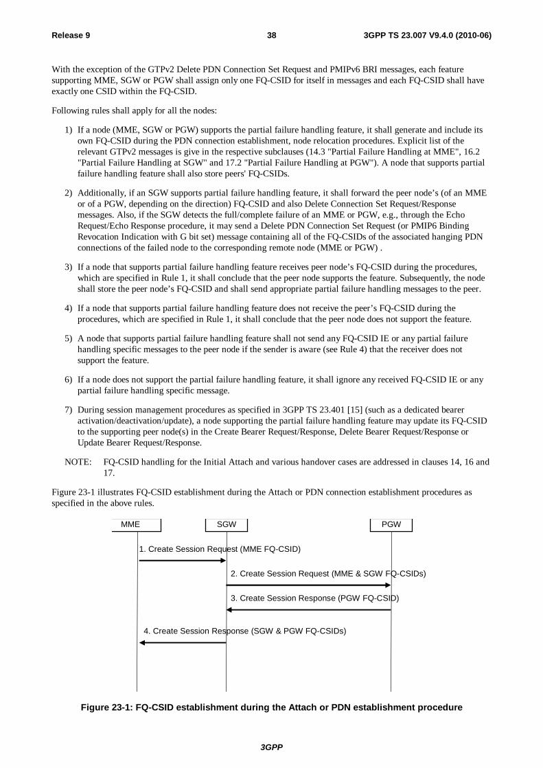
3GPP
3GPP TS 23.007 V9.4.0 (2010-06)38Release 9
With the exception of the GTPv2 Delete PDN Connection Set Request and PMIPv6 BRI messages, each feature supporting MME, SGW or PGW shall assign only one FQ-CSID for itself in messages and each FQ-CSID shall have exactly one CSID within the FQ-CSID.
Following rules shall apply for all the nodes:
1) If a node (MME, SGW or PGW) supports the partial failure handling feature, it shall generate and include its own FQ-CSID during the PDN connection establishment, node relocation procedures. Explicit list of the relevant GTPv2 messages is give in the respective subclauses (14.3 "Partial Failure Handling at MME", 16.2 "Partial Failure Handling at SGW" and 17.2 "Partial Failure Handling at PGW"). A node that supports partial failure handling feature shall also store peers' FQ-CSIDs.
2) Additionally, if an SGW supports partial failure handling feature, it shall forward the peer node’s (of an MME or of a PGW, depending on the direction) FQ-CSID and also Delete Connection Set Request/Response messages. Also, if the SGW detects the full/complete failure of an MME or PGW, e.g., through the Echo Request/Echo Response procedure, it may send a Delete PDN Connection Set Request (or PMIP6 Binding Revocation Indication with G bit set) message containing all of the FQ-CSIDs of the associated hanging PDN connections of the failed node to the corresponding remote node (MME or PGW) .
3) If a node that supports partial failure handling feature receives peer node’s FQ-CSID during the procedures, which are specified in Rule 1, it shall conclude that the peer node supports the feature. Subsequently, the node shall store the peer node’s FQ-CSID and shall send appropriate partial failure handling messages to the peer.
4) If a node that supports partial failure handling feature does not receive the peer’s FQ-CSID during the procedures, which are specified in Rule 1, it shall conclude that the peer node does not support the feature.
5) A node that supports partial failure handling feature shall not send any FQ-CSID IE or any partial failure handling specific messages to the peer node if the sender is aware (see Rule 4) that the receiver does not support the feature.
6) If a node does not support the partial failure handling feature, it shall ignore any received FQ-CSID IE or any partial failure handling specific message.
7) During session management procedures as specified in 3GPP TS 23.401 [15] (such as a dedicated bearer activation/deactivation/update), a node supporting the partial failure handling feature may update its FQ-CSID to the supporting peer node(s) in the Create Bearer Request/Response, Delete Bearer Request/Response or Update Bearer Request/Response.
NOTE: FQ-CSID handling for the Initial Attach and various handover cases are addressed in clauses 14, 16 and 17.
Figure 23-1 illustrates FQ-CSID establishment during the Attach or PDN connection establishment procedures as specified in the above rules.
1. Create Session Request (MME FQ-CSID)
SGW MME
2. Create Session Request (MME & SGW FQ-CSIDs)
PGW
3. Create Session Response (PGW FQ-CSID)
4. Create Session Response (SGW & PGW FQ-CSIDs)
Figure 23-1: FQ-CSID establishment during the Attach or PDN establishment procedure
3GPP
3GPP TS 23.007 V9.4.0 (2010-06)39Release 9
1. If an MME supports partial failure handling, the MME shall send own FQ-CSID to SGW with a Create Session Request message across S11 interface.
The MME's FQ-CSID indicates to the SGW that MME supports partial failure handling. If the SGW does not receive MME's FQ-CSID, then the SGW shall never send partial failure handling related messages or IEs to the MME.
If the SGW does not support partial failure handling, then the SGW shall silently discard MME's FQ-CSID.
If the SGW does support partial fault handling it shall store the MME's FQ-CSID in it's PDN connection table.
2. If the SGW supports partial failure handling, the SGW shall forward MME's FQ-CSID to PGW with a Create Session Request message across S5/S8 interface. The SGW shall also include own FQ-CSID into the message. The SGW's FQ-CSID indicates to the PGW that the SGW supports partial failure handling.
If the PGW does not support partial failure handling, then the PGW shall silently discard both FQ-CSIDs.
3. If the SGW has indicated the support for partial failure handling to PGW, then the PGW, which supports the feature shall send own FQ-CSID back to the SGW with a Create Session Response message across S5/S8 interface. PGW's FQ-CSIDs in the S5/S8 Create Session Response indicates to the SGW that PGW supports partial failure handling.
If the SGW has not indicated support for partial failure handling, then PGW shall never send partial failure handling related messages or IEs to the SGW.
4. If the MME has indicated the support for partial failure handling to SGW, then the SGW, which supports the feature, shall forward PGW's FQ-CSID to MME with a Create Session Response message across S11 interface. The SGW shall also include own FQ-CSID into the message.
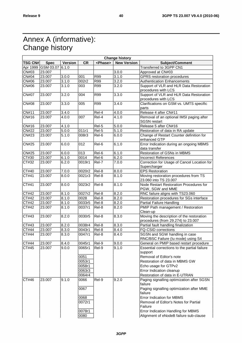
3GPP
3GPP TS 23.007 V9.4.0 (2010-06)40Release 9
Annex A (informative): Change history
Change history TSG CN# Spec Version CR <Phase> New Version Subject/Comment Apr 1999 GSM 03.07 6.1.0 Transferred to 3GPP CN1 CN#03 23.007 3.0.0 Approved at CN#03 CN#04 23.007 3.0.0 001 R99 3.1.0 GPRS restoration procedures CN#06 23.007 3.1.0 002r2 R99 3.2.0 Authentication Enhancements CN#06 23.007 3.1.0 003 R99 3.2.0 Support of VLR and HLR Data Restoration
procedures with LCS CN#07 23.007 3.2.0 004 R99 3.3.0 Support of VLR and HLR Data Restoration
procedures with LCS CN#08 23.007 3.3.0 005 R99 3.4.0 Clarifications on GSM vs. UMTS specific
parts CN#11 23.007 3.4.0 Rel-4 4.0.0 Release 4 after CN#11 CN#16 23.007 4.0.0 007 Rel-4 4.1.0 Removal of an optional IMSI paging after
SGSN restart CN#16 23.007 4.1.0 Rel-5 5.0.0 Release 5 after CN#16 CN#22 23.007 5.0.0 011r1 Rel-5 5.1.0 Restoration of data in RA update CN#23 23.007 5.1.0 008r3 Rel-6 6.0.0 Change of Restart Counter definition for
enhanced GTP CN#25 23.007 6.0.0 012 Rel-6 6.1.0 Error Indication during an ongoing MBMS
data transfer CN#25 23.007 6.0.0 013 Rel-6 6.1.0 Restoration of GSNs in MBMS CT#30 23.007 6.1.0 0014 Rel-6 6.2.0 Incorrect References CT#32 23.007 6.2.0 0019r1 Rel-7 7.0.0 Correction for Usage of Cancel Location for
Supercharger CT#40 23.007 7.0.0 0020r2 Rel-8 8.0.0 EPS Restoration CT#41 23.007 8.0.0 0021r3 Rel-8 8.1.0 Moving restoration procedures from TS
23.060 into TS 23.007 CT#41 23.007 8.0.0 0023r2 Rel-8 8.1.0 Node Restart Restoration Procedures for
PGW, SGW and MME CT#42 23.007 8.1.0 0027r2 Rel-8 8.2.0 RNC failure aligns with TS23.060 CT#42 23.007 8.1.0 0028 Rel-8 8.2.0 Restoration procedures for SGs interface CT#42 23.007 8.1.0 0033r5 Rel-8 8.2.0 Partial Failure Handling CT#42 23.007 8.1.0 0037r1 Rel-8 8.2.0 PMIP Path management / Restoration
Clean-up CT#43 23.007 8.2.0 0030r5 Rel-8 8.3.0 Moving the description of the restoration
procedures (from 29.274) to 23.007 CT#43 23.007 8.2.0 0038r4 Rel-8 8.3.0 Partial fault handling finalization CT#44 23.007 8.3.0 0043r1 Rel-8 8.4.0 FQ-CSID corrections CT#44 23.007 8.3.0 0047r1 Rel-8 8.4.0 SGSN and SGW handling in case
RNC/BSC Failure (Iu mode) using S4 CT#44 23.007 8.4.0 0045r1 Rel-9 9.0.0 General on PMIP based restart procedure CT#45 23.007 9.0.0 0065r1 Rel-9 9.1.0 Essential corrections to the partial failure
support 0051 Removal of Editor's note 0053r1 Restoration of data in MBMS GW 0058r1 Echo usage for GTPv2 0063r3 Error Indication cleanup 0064r4 Restoration of data in E-UTRAN CT#46 23.007 9.1.0 0066 Rel-9 9.2.0 Paging signalling optimization after SGSN
failure 0067 Paging signalling optimization after MME
failure 0068 Error Indication for MBMS 0072r1 Removal of Editor's Notes for Partial
Failure 0078r1 Error Indication Handling for MBMS 0080 Alignment of eNodeB failure sub-clause
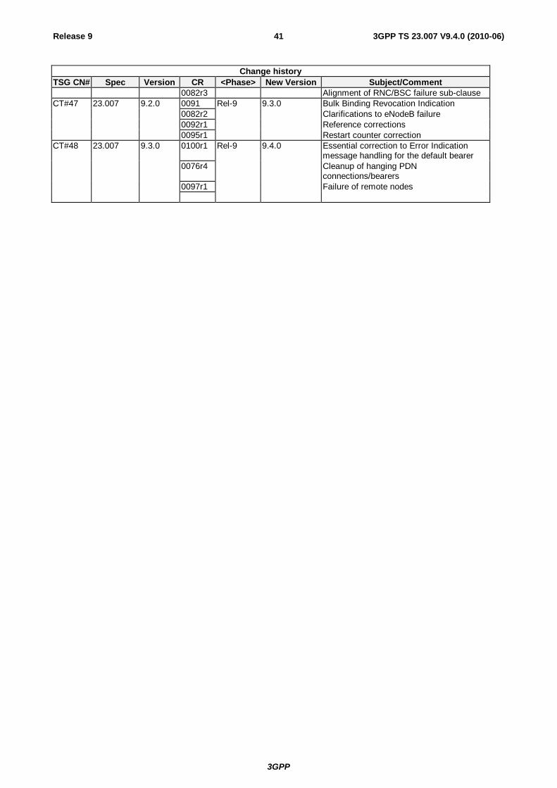
3GPP
3GPP TS 23.007 V9.4.0 (2010-06)41Release 9
Change history TSG CN# Spec Version CR <Phase> New Version Subject/Comment 0082r3 Alignment of RNC/BSC failure sub-clause CT#47 23.007 9.2.0 0091 Rel-9 9.3.0 Bulk Binding Revocation Indication 0082r2 Clarifications to eNodeB failure 0092r1 Reference corrections 0095r1 Restart counter correction CT#48 23.007 9.3.0 0100r1 Rel-9 9.4.0 Essential correction to Error Indication
message handling for the default bearer 0076r4 Cleanup of hanging PDN
connections/bearers 0097r1 Failure of remote nodes