Embed Size (px)
DESCRIPTION
3M™ Attest™ Sterile U Web Meeting March 19, 2009. How Long Did They Go? Healthcare Facilities Share Flash Reduction Best Practices. Welcome!. Facilitator: Tammy Torbert, 3M Sterilization Assurance Speaker: Dorothy Larson, 3M Technical Service - PowerPoint PPT Presentation
Citation preview

© 3M 2009. All Rights Reserved.
3M™ Attest™ Sterile U Web MeetingMarch 19, 2009
How Long Did They Go? Healthcare Facilities Share Flash Reduction Best Practices

© 3M 2009. All Rights Reserved.
2
Welcome!
Facilitator: Tammy Torbert, 3M Sterilization Assurance
Speaker: Dorothy Larson, 3M Technical Service
Panelist: Francis Zieman, 3M Technical Service
Housekeeping: Questions;
-Mute feature (*7=unmute; *6=mute)-“Chat” feature
Technical difficulties CE Credits Post session follow-up
For more information: www.3M.com/AttestSterileUOnline

© 3M 2009. All Rights Reserved.
3
Discussion Topics
1. Define flash sterilization
2. Discuss the Association of periOperative Registered Nurses (AORN) and the Association for the Advancement of Medical Instrumentation’s (AAMI’s) recommended practice on flash sterilization
3. Discuss issues associated with flash sterilization
4. Describe an effective quality assurance program for flash sterilization
5. Discuss Flash Reduction Best Practices
© 3M 2009. All Rights Reserved.
4
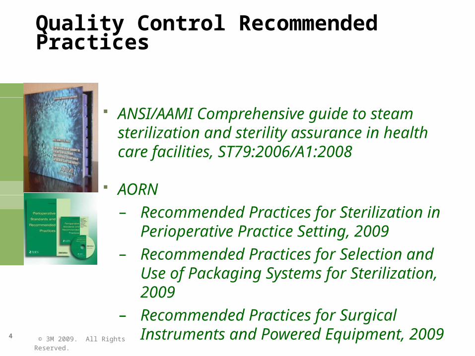
Quality Control Recommended Practices
ANSI/AAMI Comprehensive guide to steam sterilization and sterility assurance in health care facilities, ST79:2006/A1:2008
AORN– Recommended Practices for Sterilization in
Perioperative Practice Setting, 2009– Recommended Practices for Selection and Use of
Packaging Systems for Sterilization, 2009– Recommended Practices for Surgical Instruments
and Powered Equipment, 2009
© 3M 2009. All Rights Reserved.
5
AAMI and AORN
AAMIGuidelines for the use, care and/or processing of medical device or system to ensure a device is used safely and effectively and its performance will be maintained
AORN Standards and recommended practices serve as the basis for policies and procedures
Promote safety and optimal outcomes for patients
© 3M 2009. All Rights Reserved.
6
Flash Sterilization
Process designed for the steam sterilization of patient care items for immediate use.
AAMI ST79
© 3M 2009. All Rights Reserved.
7
Flash Sterilization - History
Reprocessing of dropped instruments mid-procedure
Unwrapped, 270 deg. F. Gravity cycle only-No dry time
High Temperature Sterilization
AAMI ST79
© 3M 2009. All Rights Reserved.
8
Flash Sterilization - Today
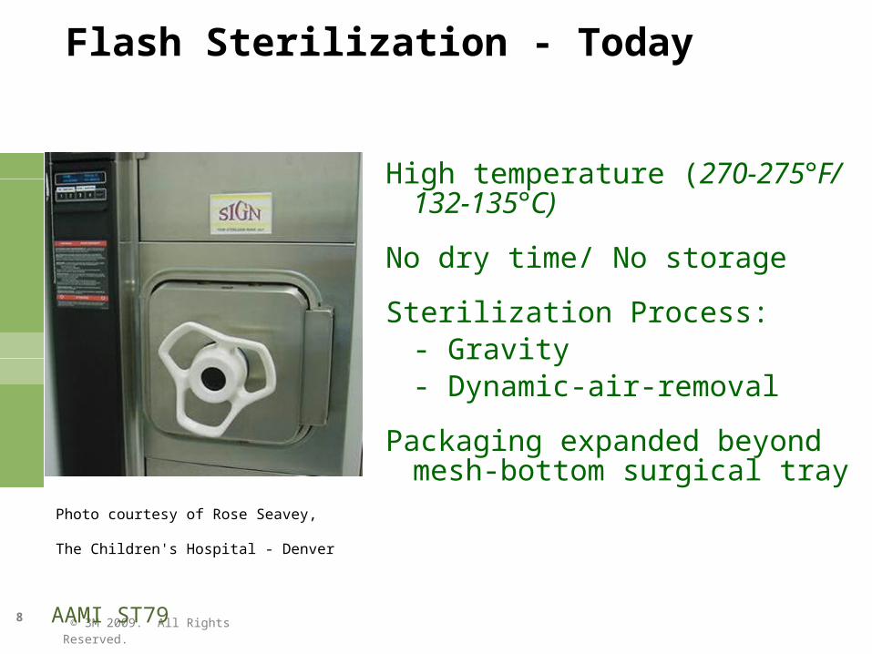
High temperature (270-275°F/ 132-135°C)
No dry time/ No storage
Sterilization Process:- Gravity- Dynamic-air-removal
Packaging expanded beyond mesh-bottom surgical tray
AAMI ST79
Photo courtesy of Rose Seavey, The Children's Hospital - Denver
© 3M 2009. All Rights Reserved.
9
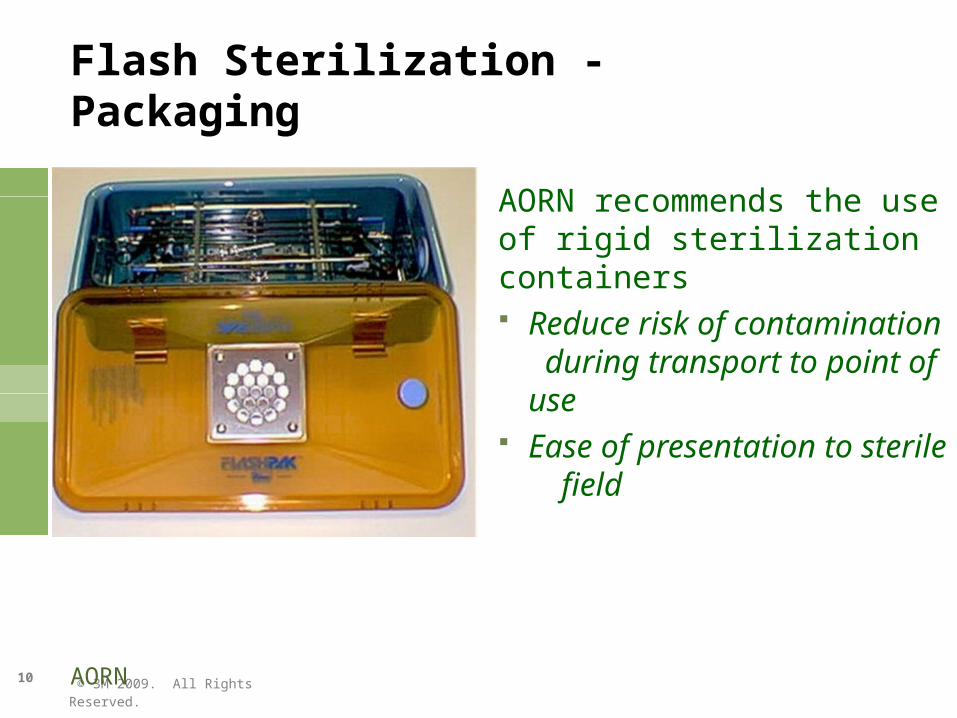
Flash Sterilization - Packaging
Perforated, mesh bottom, open surgical tray Rigid sterilization container system Protective organizing case Single-wrapped surgical tray
AAMI ST79
© 3M 2009. All Rights Reserved.
10
AORN recommends the use of rigid sterilization containers Reduce risk of contamination
during transport to point of use Ease of presentation to sterile
field
AORN
Flash Sterilization - Packaging

© 3M 2009. All Rights Reserved.
11
Types of Steam Sterilization Processes
Gravity Displacement
Dynamic-Air-Removal by Prevaccuum Steam-flush pressure-pulse (SFPP)
AAMI ST79
© 3M 2009. All Rights Reserved.
12
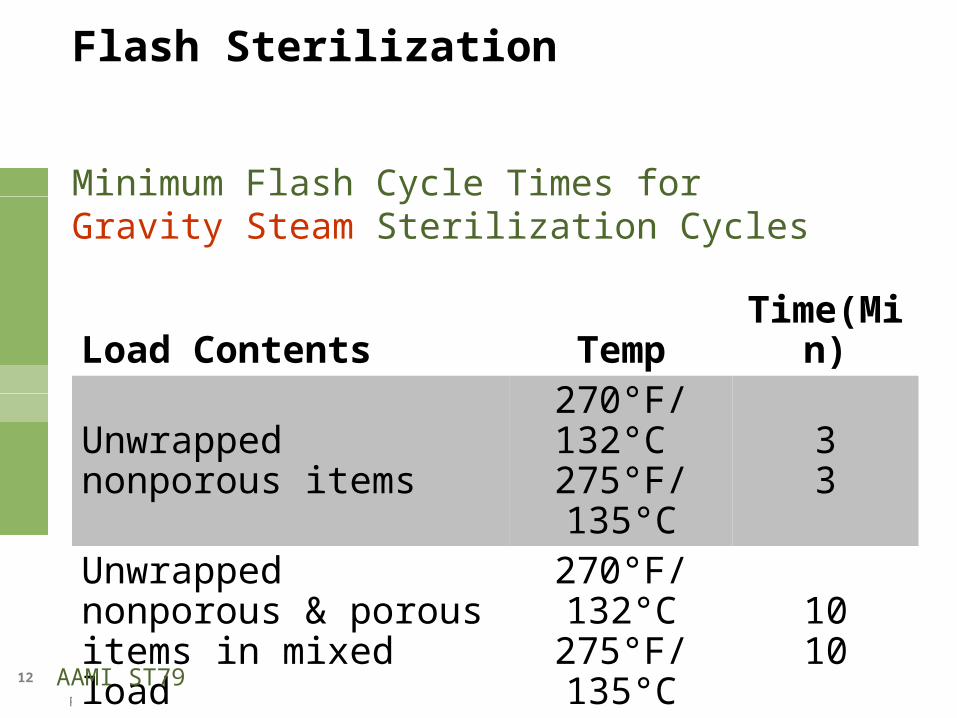
Minimum Flash Cycle Times for Gravity Steam Sterilization Cycles
Flash Sterilization
Load Contents Temp Time(Min)
Unwrapped nonporous items 270°F/132°C 275°F/135°C
33
Unwrapped nonporous & porous items in mixed load
270°F/132°C275°F/135°C
1010
AAMI ST79
© 3M 2009. All Rights Reserved.
13
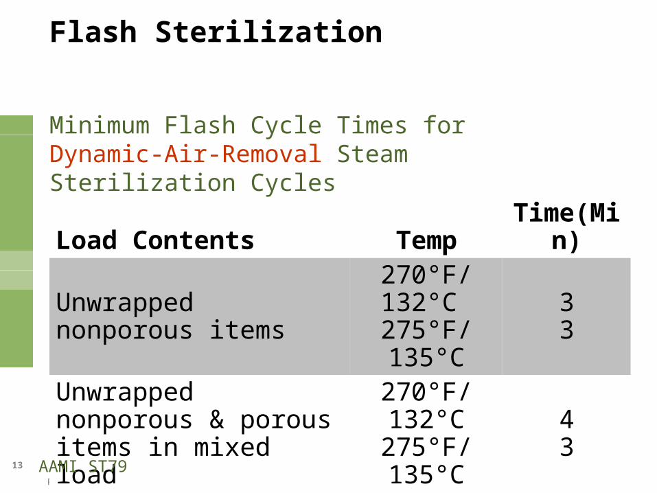
Minimum Flash Cycle Times for Dynamic-Air-Removal Steam Sterilization Cycles
Flash Sterilization
Load Contents Temp Time(Min)
Unwrapped nonporous items 270°F/132°C 275°F/135°C
33
Unwrapped nonporous & porous items in mixed load
270°F/132°C275°F/135°C
43
AAMI ST79
© 3M 2009. All Rights Reserved.
14
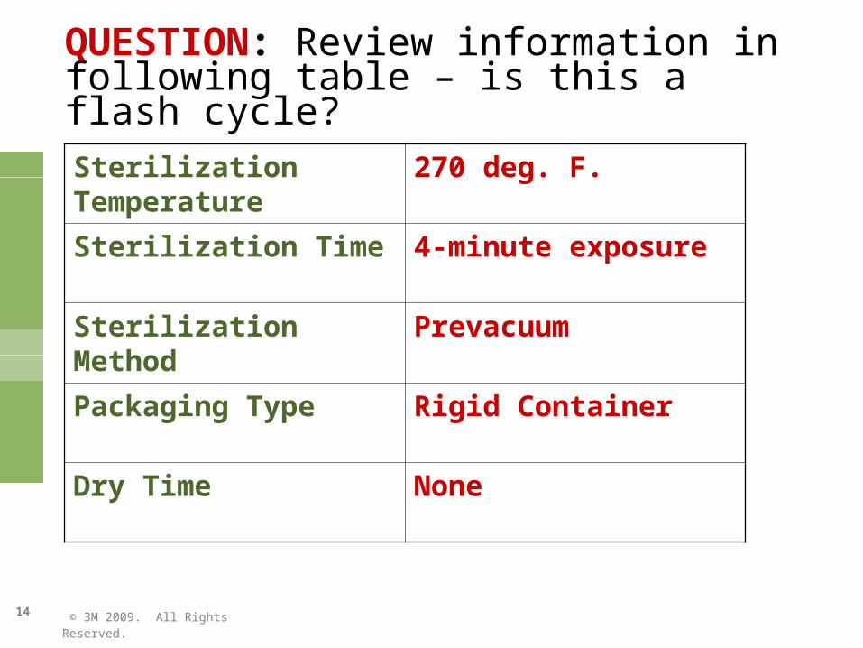
QUESTION: Review information in following table – is this a flash cycle?
Sterilization Temperature 270 deg. F.
Sterilization Time 4-minute exposure
Sterilization Method Prevacuum
Packaging Type Rigid Container
Dry Time None
© 3M 2009. All Rights Reserved.
15
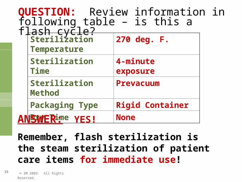
QUESTION: Review information in following table – is this a flash cycle?
Sterilization Temperature 270 deg. F.
Sterilization Time 4-minute exposure
Sterilization Method Prevacuum
Packaging Type Rigid Container
Dry Time None
ANSWER: YES!
Remember, flash sterilization is the steam sterilization of patient care items for immediate use!
© 3M 2009. All Rights Reserved.
16
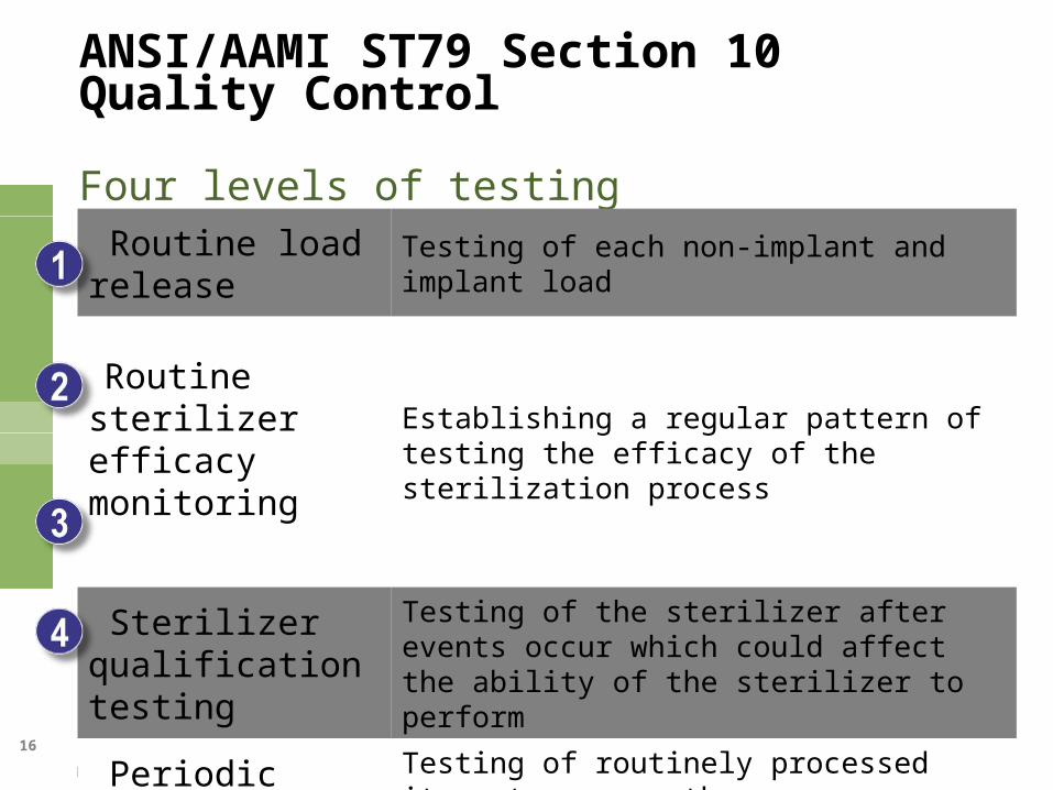
ANSI/AAMI ST79 Section 10 Quality Control
Four levels of testing
Routine load release Testing of each non-implant and implant load
Routine sterilizer efficacy monitoring
Establishing a regular pattern of testing the efficacy of the sterilization process
Sterilizer qualification testing
Testing of the sterilizer after events occur which could affect the ability of the sterilizer to perform
Periodic product testing
Testing of routinely processed items to ensure the effectiveness of the sterilization process and to avoid wet packs
© 3M 2009. All Rights Reserved.
17
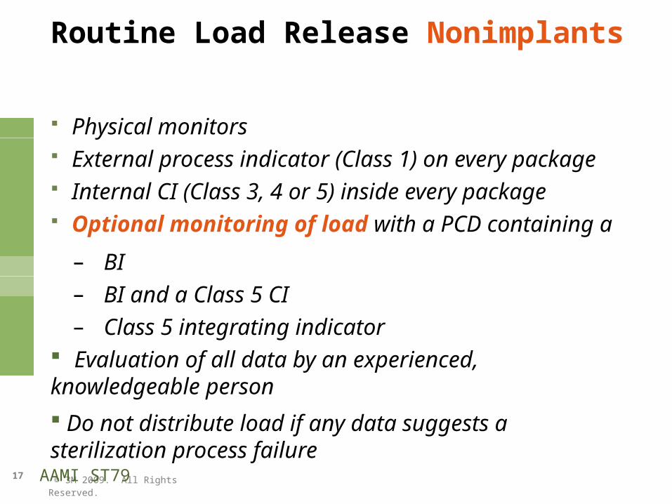
Routine Load Release Nonimplants
Physical monitors External process indicator (Class 1) on every package Internal CI (Class 3, 4 or 5) inside every package Optional monitoring of load with a PCD containing a
– BI– BI and a Class 5 CI – Class 5 integrating indicator
Evaluation of all data by an experienced, knowledgeable person
Do not distribute load if any data suggests a sterilization process failure
AAMI ST79
© 3M 2009. All Rights Reserved.
18
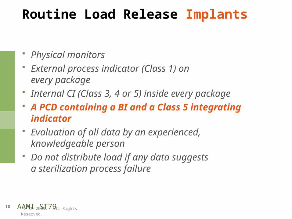
Routine Load Release Implants
Physical monitors External process indicator (Class 1) on
every package Internal CI (Class 3, 4 or 5) inside every package A PCD containing a BI and a Class 5 integrating indicator Evaluation of all data by an experienced, knowledgeable
person Do not distribute load if any data suggests
a sterilization process failure
AAMI ST79
© 3M 2009. All Rights Reserved.
19
Sterilization Process Monitoring Tools
Physical Monitors
Chemical Indicators
Biological Indicators
© 3M 2009. All Rights Reserved.
20
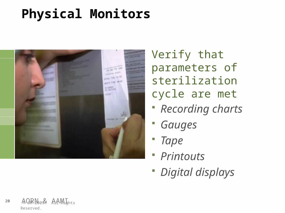
Physical Monitors
Verify that parameters of sterilization cycle are met Recording charts Gauges Tape Printouts Digital displays
AORN & AAMI
© 3M 2009. All Rights Reserved.
21
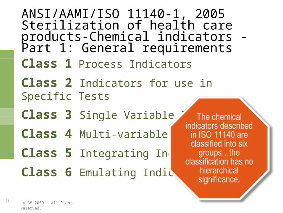
ANSI/AAMI/ISO 11140-1, 2005 Sterilization of health care products-Chemical indicators - Part 1: General requirements
Class 1 Process Indicators
Class 2 Indicators for use in Specific Tests
Class 3 Single Variable Indicators
Class 4 Multi-variable Indicators
Class 5 Integrating Indicators
Class 6 Emulating Indicators
© 3M 2009. All Rights Reserved.
22
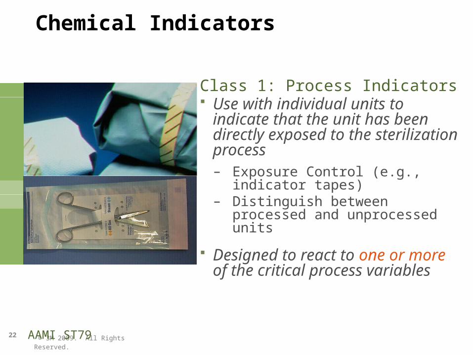
Chemical Indicators
Class 1: Process Indicators Use with individual units to indicate
that the unit has been directly exposed to the sterilization process – Exposure Control (e.g., indicator
tapes)– Distinguish between processed and
unprocessed units
Designed to react to one or more of the critical process variables
AAMI ST79
© 3M 2009. All Rights Reserved.
23
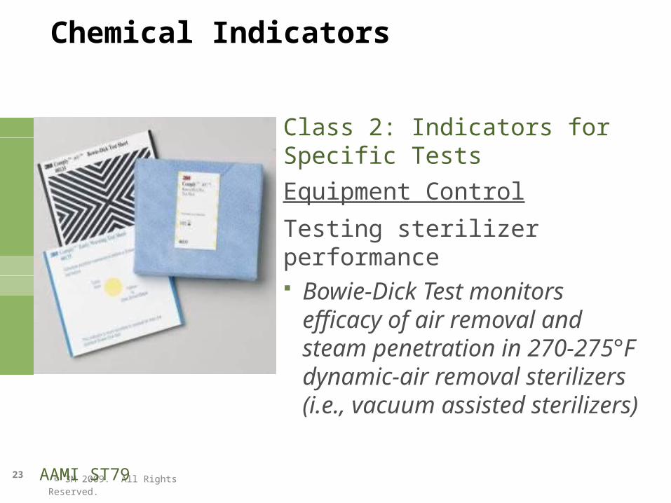
Chemical Indicators
Class 2: Indicators for Specific TestsEquipment Control
Testing sterilizer performance Bowie-Dick Test monitors efficacy of
air removal and steam penetration in 270-275°F dynamic-air removal sterilizers (i.e., vacuum assisted sterilizers)
AAMI ST79
© 3M 2009. All Rights Reserved.
24
Chemical Indicators
Internal CIs – Class 3, 4, 5 Tests conditions inside individual packs
Internal chemical indicator inside each package Use inside each pack, wrapped tray, flash tray or container in
area least accessible to sterilant – identifies sterilant penetrated
AORN & AAMI
© 3M 2009. All Rights Reserved.
25
AORN
Placement of internal chemical indicators
AORN
© 3M 2009. All Rights Reserved.
26
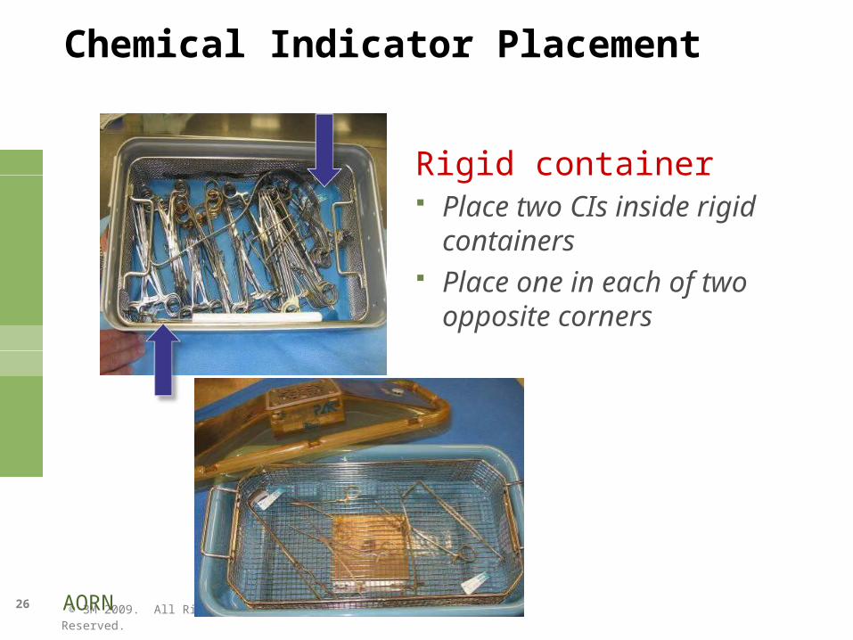
Chemical Indicator Placement
Rigid container Place two CIs inside rigid containers Place one in each of two opposite
corners
AORN
© 3M 2009. All Rights Reserved.
27
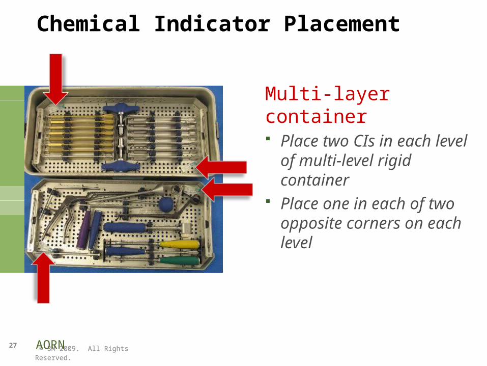
Chemical Indicator Placement
Multi-layer container Place two CIs in each level of
multi-level rigid container Place one in each of two
opposite corners on each level
AORN
© 3M 2009. All Rights Reserved.
28
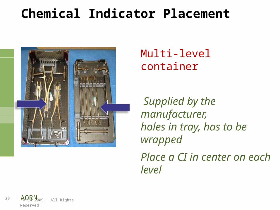
Chemical Indicator Placement
Multi-level container
Supplied by the manufacturer,holes in tray, has to be wrapped
Place a CI in center on each level
AORN
© 3M 2009. All Rights Reserved.
29
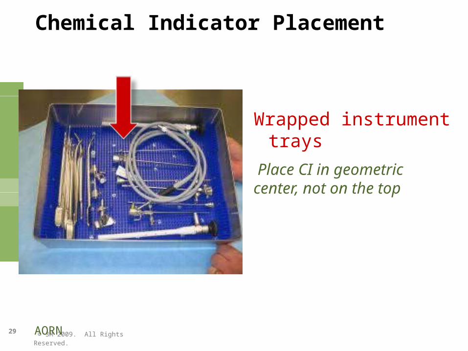
Chemical Indicator Placement
Wrapped instrument trays
Place CI in geometric center, not on the top
AORN
© 3M 2009. All Rights Reserved.
30
Routine Load Release Nonimplants – Flash Sterilization
Class 5 Integrating Indicator PCD for releasing flash loads PCD must be representative of load
– Open surgical tray– Rigid sterilization container– Protective organization case– Single-wrapped surgical tray
Class 5 Integrating Indicator also serves as internal CI
AAMI ST79
© 3M 2009. All Rights Reserved.
31
Biological Indicators
DefinitionTest system containing viable microorganisms providing a defined resistance to a specified sterilization process
AAMI ST79
© 3M 2009. All Rights Reserved.
32
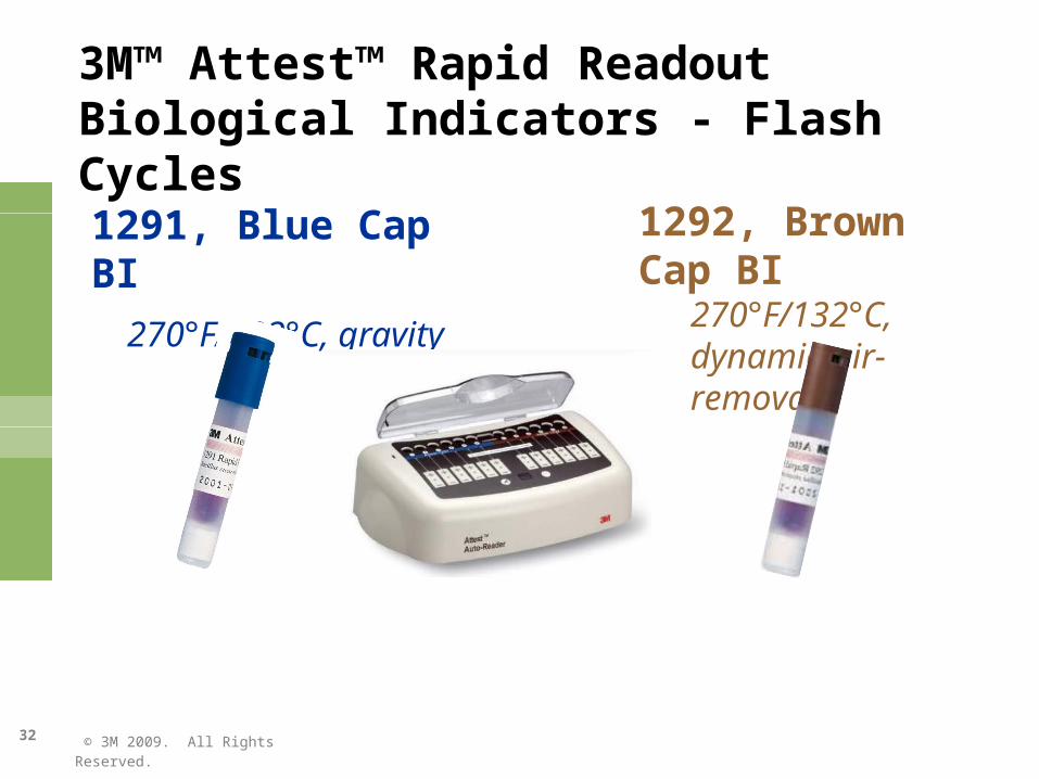
3M™ Attest™ Rapid Readout Biological Indicators - Flash Cycles
1291, Blue Cap BI
270°F/132°C, gravity
1292, Brown Cap BI270°F/132°C, dynamic-air-removal
© 3M 2009. All Rights Reserved.
33
Biological Indicators AAMI ST79
AAMI and AORN - Weekly, preferably daily and implants
AAMI ST79 & AORN
© 3M 2009. All Rights Reserved.
34
Routine Load Release Implant Loads
“Emergency situations should be defined”
AAMI ST79
© 3M 2009. All Rights Reserved.
35
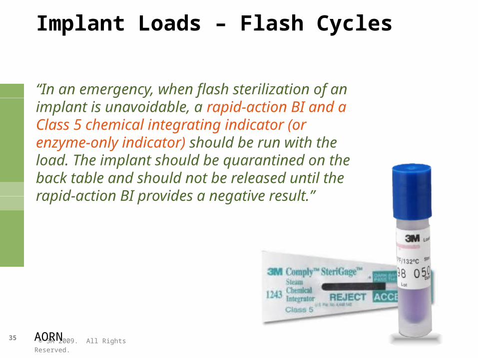
Implant Loads – Flash Cycles
“In an emergency, when flash sterilization of an implant is unavoidable, a rapid-action BI and a Class 5 chemical integrating indicator (or enzyme-only indicator) should be run with the load. The implant should be quarantined on the back table and should not be released until the rapid-action BI provides a negative result.”
AORN

© 3M 2009. All Rights Reserved.
36
Biological Indicators
“Rationale: The use of BIs provides evidence of efficacy by challenging the sterilizer with a large number of highly resistant bacterial spores. Biological monitoring provides the only direct measure of the lethality of a sterilization cycle. Sterilizer manufacturers validate their sterilization cycles using BIs; therefore, routine sterilizer efficacy monitoring in health care facilities should also be conducted using BIs.” (section 10.5.3.2)
AAMI ST79
© 3M 2009. All Rights Reserved.
37
Record Keeping
“Documentation establishes accountability.”AORN Sterilization Recommended Practice
AORN
© 3M 2009. All Rights Reserved.
38
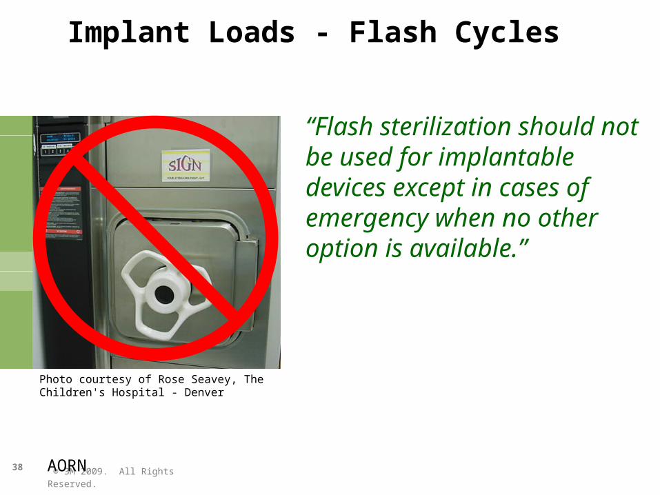
Implant Loads - Flash Cycles
“Flash sterilization should not be used for implantable devices except in cases of emergency when no other option is available.”
AORN
Photo courtesy of Rose Seavey, The Children's Hospital - Denver
© 3M 2009. All Rights Reserved.
39
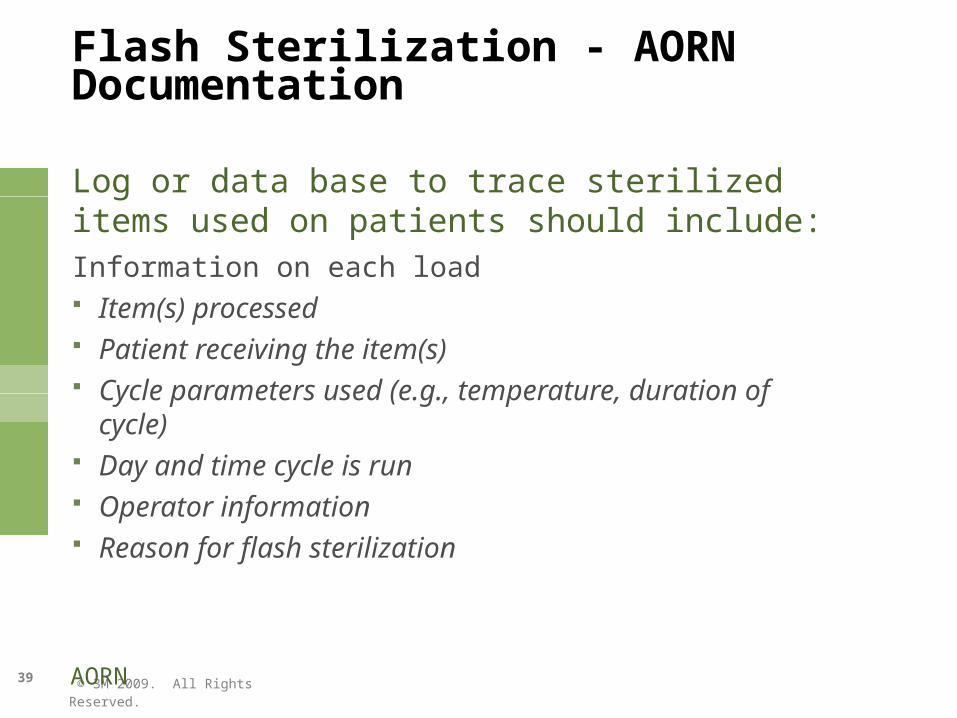
Flash Sterilization - AORN Documentation
Log or data base to trace sterilized items used on patients should include:Information on each load Item(s) processed Patient receiving the item(s) Cycle parameters used (e.g., temperature, duration of cycle) Day and time cycle is run Operator information Reason for flash sterilization
AORN
© 3M 2009. All Rights Reserved.
40
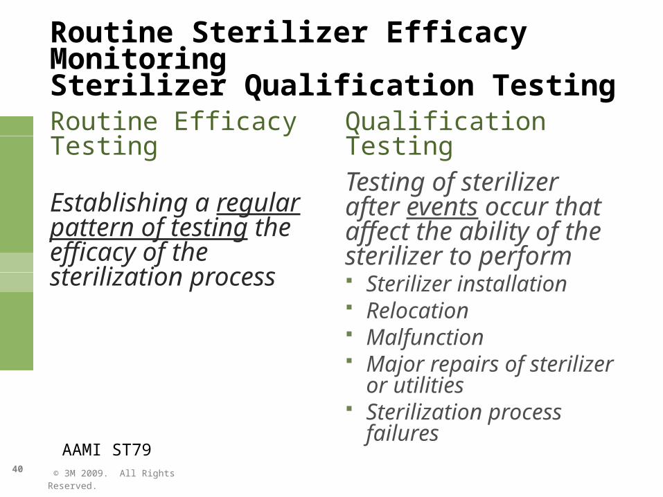
Routine Sterilizer Efficacy MonitoringSterilizer Qualification Testing
Routine Efficacy Testing
Establishing a regular pattern of testing the efficacy of the sterilization process
Qualification TestingTesting of sterilizer after events occur that affect the ability of the sterilizer to perform Sterilizer installation Relocation Malfunction Major repairs of sterilizer or
utilities Sterilization process failures
AAMI ST79
© 3M 2009. All Rights Reserved.
41
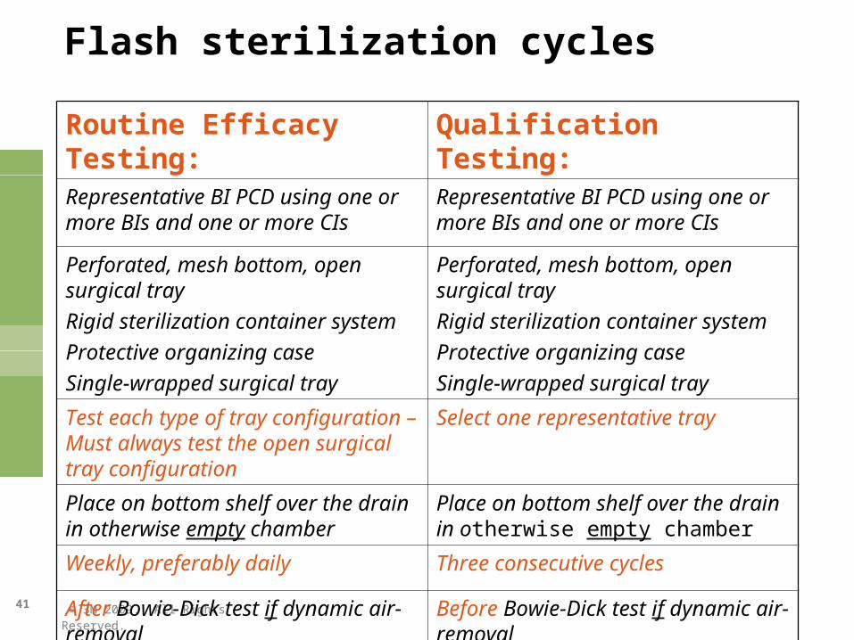
Flash sterilization cycles
Routine Efficacy Testing: Qualification Testing:Representative BI PCD using one or more BIs and one or more CIs
Representative BI PCD using one or more BIs and one or more CIs
Perforated, mesh bottom, open surgical tray
Rigid sterilization container system
Protective organizing case
Single-wrapped surgical tray
Perforated, mesh bottom, open surgical tray
Rigid sterilization container system
Protective organizing case
Single-wrapped surgical tray
Test each type of tray configuration – Must always test the open surgical tray configuration
Select one representative tray
Place on bottom shelf over the drain in otherwise empty chamber
Place on bottom shelf over the drain in otherwise empty chamber
Weekly, preferably daily Three consecutive cycles
After Bowie-Dick test if dynamic air-removal Before Bowie-Dick test if dynamic air-removal
© 3M 2009. All Rights Reserved.
42
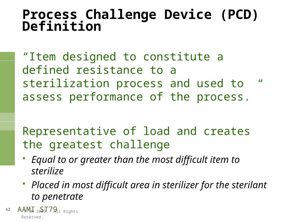
Process Challenge Device (PCD) Definition
“Item designed to constitute a defined resistance to a sterilization process and used to assess performance of the process.”
Representative of load and creates the greatest challenge Equal to or greater than the most difficult item to sterilize Placed in most difficult area in sterilizer for the sterilant
to penetrate
AAMI ST79
© 3M 2009. All Rights Reserved.
43
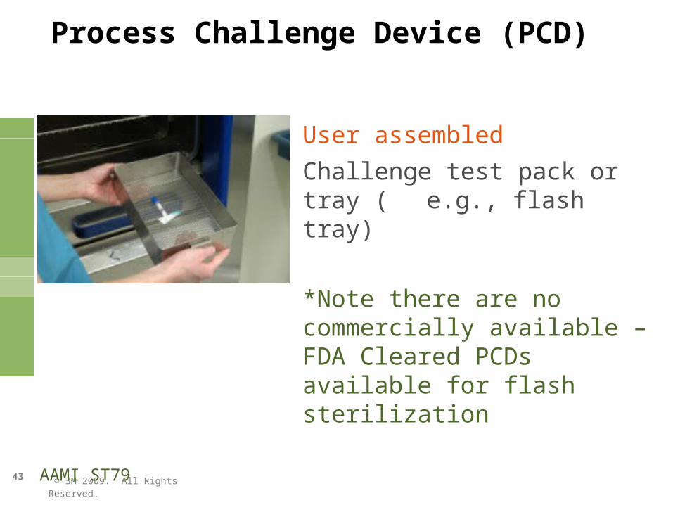
Process Challenge Device (PCD)
User assembledChallenge test pack or tray (e.g., flash tray)
*Note there are no commercially available – FDA Cleared PCDs available for flash sterilization
AAMI ST79
© 3M 2009. All Rights Reserved.
44
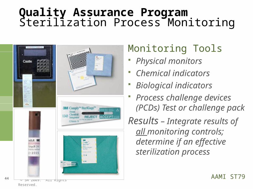
Quality Assurance ProgramSterilization Process Monitoring
Monitoring Tools Physical monitors Chemical indicators Biological indicators Process challenge devices (PCDs)
Test or challenge pack
Results – Integrate results of all monitoring controls; determine if an effective sterilization process
AAMI ST79
© 3M 2009. All Rights Reserved.
45
If a biological indicator (BI) is positive, do you only recall that load?
QUESTION:
© 3M 2009. All Rights Reserved.
46
QUESTION: If a BI is positive, do you only recall that load?
ANSWER:
If determined to be an operator error e.g.,.. using incorrect sterilization
cycle No recall, don’t use load
If not operator error or don’t know reason Recall all items processed since last
negative BI Reprocess all retrieved items
© 3M 2009. All Rights Reserved.
47
Biological Indicator Monitoring Frequency
Why monitor every load? Universal standard of patient care Reduces variability and chance for errors To be certain all implants, including those in loaners sets, are
appropriately monitored To ensure all cycle types used are tested with a BI
To ensure all types of packaging used in flash sterilization are tested with a BI To reduce the risk, cost, and impact of a recall To reduce the risk/cost of healthcare-associated infections (HIAs)
© 3M 2009. All Rights Reserved.
48
The Joint Commission
Organizational policies/procedures should be based on most stringent: Laws and regulations Accepted practice guidelines Current scientific knowledge And, are consistent throughout facility
© 3M 2009. All Rights Reserved.
49
Issues Associated with Flash Sterilization
Time Pressures– skipped steps in cleaning/decontamination
Flashing large and/or multiple trays– increases cycle and cooling time
Loaner Instrumentation
AAMI ST79
© 3M 2009. All Rights Reserved.
50
Loaner Instrumentation Issues
Patient Safety Timelines (flashing is not recommended) Communication (OR, SPD, Vendor) Quality
– MDM Reprocessing Guidelines– Adequate time– Implants
Potential for lost items

© 3M 2009. All Rights Reserved.
51
Toxic Anterior Segment Syndrome - TASS
The Issue: serious damage to a patient’s intraocular tissue and vision loss as a result of contaminants in the eye during ophthalmic surgeryCauses: contaminated irrigating fluids; antiseptics; antibiotic ointments; powder from surgical gloves “Most cases of TASS appear to result from inadequate instrument cleaning and sterilization”
Nick Mamalis, MD, Toxic Anterior Segment Syndrome Journal of Cataract and Refractive Surgery 2006; 32:324-333.
© 3M 2009. All Rights Reserved.
52
Toxic Anterior Segment Syndrome - TASS
Inadequate or inappropriate instrument cleaning “Detergents Heat stable endotoxin from overgrowth of gram-negative bacilli in water baths or ultrasonic cleaners Degradation of brass containing surgical instruments from plasma gas sterilization Impurities of autoclave steam”
Recommended practices for cleaning and sterilizing intraocular surgical instruments, J Cataract Refract Surg, Vol 33, June 2007
© 3M 2009. All Rights Reserved.
53
AAMI ST79 2008 Amendments - Annex N (informative)Toxic anterior segment syndrome (TASS) and the processing of surgical instruments
Follow Mfr’s. cleaning and sterilization instructions Adequate inventory-time for processing Designated cleaning area and dedicated equipment Precleaned immediately Transport in closed containers PPE Appropriate cleaning agent & water of appropriate quality as specified
by the Mfr. Sterilization according the Mfr’s. instructions Maintenance of cleaning and sterilization equipment, boilers and water
filtration systems Training

© 3M 2009. All Rights Reserved.
Thank You!

© 3M 2009. All Rights Reserved.
55
SHARING FLASH REDUCTION “BEST PRACTICES”