Embed Size (px)
Citation preview
4 Highway Lighting Construction Requirements Excavation Trench Excavation Foundation Excavation Landscape Replacement Backfilling Placing Conduit Connections in Base of Lighting Standards Placing Wire and Cable Underground Through Cable-Duct Cable-Duct Cable Markers Underground Through Conduit Cable-Duct Cable Markers In Conduit Risers Through Conduit in Bridge Coping Aerial Cable Lighting Handholes Concrete Foundations for Lighting Standards Cast-In-Place Foundations Precast Foundations Grading of Foundations Placing Lighting Standards Lighting Standards Under 80 ft in Height High Mast Lighting Standards 80 ft Height and Over Grounding Luminaire Installation Roadway Luminaires Sign Luminaires
Underpass Luminaires High Mast Luminaires Sign, Underpass, Roadway, and High Mast Lighting Location Identification Service Point Power Entry Types of Service Points Sign and Underpass Circuits Multiple Relay Switches Testing of Highway Lighting System Testing Lighting Circuitry Testing and Inspecting Luminaires Pay Item and Installation Summary Sheets Method of Measurement
4-1
CHAPTER FOUR: HIGHWAY LIGHTING
Highway lighting consists of installing wire, cable, conduit, lighting standards, luminaires, lamps, and incidental materials in accordance with the Specifications and in reasonably close conformance with the lines, grades, and locations shown on the plans, or as directed. Lighting installations are required to be in accordance with the National Electrical Code and the National Safety Code. Existing highway illumination is maintained on all contracts unless discontinuance of the highway illumination is specifically permitted. Manufacturers' descriptive and technical literature for major items is required to be submitted for approval. Where normal trade practice requires the manufacturer to furnish a warranty, a warranty is furnished on all major items such as luminaires, lamps, poles, brackets, cable-duct, wire and cable, fuse connectors, and ballasts. The effective date of the warranty commences on the date of final acceptance. These items are required to bear the seal of approval of the Underwriters Laboratory. All flexible conduit is required to be galvanized steel, polyvinyl jacketed, and watertight. Reinforcing steel is required to be epoxy coated.
CONSTRUCTION REQUIREMENTS
EXCAVATION
All excavation for the roadway lighting installation is conducted in accordance with the dimensions, elevations, and grades shown on the plans, or as directed. If class X material is encountered, foundation excavation is completed in accordance with Section 206.
TRENCH EXCAVATION
Excavation may be done either manually or with mechanical trenching equipment. The blades of road patrols or graders are not used to excavate the trenches. The depth of trenches is required to be a minimum of 2 ft. Walls of trenches for cable-duct or conduit are essentially vertical. The bottoms of trenches are smooth and free from aggregate larger than 1/2 in. Bracing, shoring, and sheathing are provided as necessary. If the
4-2
excavation is below the required level, the excess excavated area is refilled in a satisfactory manner with no additional payment. The accumulation of water in excavated areas is prevented by the use of pumps or other approved means. When rocks or other materials which might damage the cable- duct or conduit are encountered, the excavation is extended to a depth of at least 27 in. and backfilled with a 3 in. compacted layer of sand or earth containing no particles that are retained on a 1/4 in. sieve. No extra payment is made for this additional excavation or backfill.
FOUNDATION EXCAVATION
If possible, excavation for concrete foundations is done by means of drilling with an auger of sufficient size to admit the width of the foundation. Work is scheduled so that all open excavations are poured with concrete during the workday they are dug. No excavations may remain open over night or over a weekend or holiday. Accumulated water is removed from the excavation before concrete is poured. If class X material is encountered, foundation excavation is completed in accordance with Section 206.02(b).
LANDSCAPE REPLACEMENT
Where roadside shrub plantings interfere with the location of illumination installations, the plantings are reset at other locations and at such times as directed in accordance with Section 622. The cost of this work is not paid for directly, but is included in the costs of other pay items. All slopes for foundation grading are required to be sodded. Sod is placed in accordance with Section 621.
BACKFILLING
Wherever practicable, all suitable materials removed from the excavated areas are used in refilling cable-duct and conduit trenches. No excavated material is wasted without authorization. Materials authorized to be wasted are disposed of as approved. Backfill for trenches is placed in layers not to exceed 6 in. by loose measurement. The first layer is sand or earth containing no particles or lumps that would be retained on a 1/4 in. sieve. The second layer contains no particles or lumps that would be retained on a 1 in. sieve. Subsequent layers may contain no particles or lumps that would be retained on a 3 in. sieve. The second layer and each subsequent layer is compacted with pneumatic hand tamps to the satisfaction of the PE/PS to prevent any future settlement of the backfilled area. Backfilling of cable-duct and conduit trenches around lighting standard foundations, handholes, manholes, and other structures is required to be in accordance with the applicable provisions of Section 211. Finish grading of earthwork is accomplished in a satisfactory manner.
4-3
PLACING CONDUIT
Conduit is placed as shown on the plans and in accordance with the applicable provisions of Section 805.11. Conduit is required to be of a size to readily permit the passing of the cable-duct being used. Conduit installed under pavement is extended a minimum of 2 ft beyond the edge of the paved surface or improved shoulder. The ends of such conduit terminates a nominal 2 ft below the ground surface. The ends are pitched so as to provide a positive drain to the surrounding soil. The ends are protected by threaded cap fittings until the time of installation of cable or cable-duct. Threaded bushing fittings are used on all ends before cable installation. Conduits installed in bridge railing concrete sections terminate a minimum of 2 ft beyond the end of the bridge railing outside of the paved surface and a minimum of 2 ft under the ground surface. Existing conduit is extended as necessary to satisfy these requirements. Hot-dipped galvanized, malleable pipe straps and spacers are used to attach conduit to bridge structures. Galvanized steel conduit hangers or pipe clamps are not permitted. Pipe straps of the proper size are installed 4 ft center to center along the conduit. When fastening pipe straps to concrete, a 3/8 in. by 2 1/2 in. galvanized steel lag screw, with an approved sleeve, is used; however, other approved expansion anchors may be used. The pipe strap and spacer are bolted to the steel beams. Conduit for service supply are mounted on a service pole, either company or INDOT owned, near the right-of-way line. For simple supply circuits, one straight, continuous, conduit riser is used. The top end terminates with a weatherhead device, and the lower end terminates at least 2 ft below ground level with a threaded grounding bushing fitting. Unless otherwise directed, the weatherhead is 24 ft above the ground. However, the actual elevation of the weatherhead is required to meet the requirements of the utility concerned.
CONNECTIONS IN BASE OF LIGHTING STANDARDS
Conductors are required to be electrically bonded to each other, as required to satisfy circuit requirements, by means of compression type fittings of the style and type shown on the plans. Inhibitor compound is used on each compression connection. Conductor identification is maintained by connecting like color connectors. A multiple conductor compression fitting is used to connect supply conductors, and an insulating link is used to provide an extension as shown on the plans. These fittings are covered with snap-on fiber or plastic covers designed to protect them from electrical contact. Taping is not permitted. The bare extension of the supply conductor from the multiple fitting to the insulation link is no longer than necessary to admit the application of the snap-on cover for the multiple fitting.
4-4
The pole circuits are connected by means of easily separated, single conductor connector kits. The connector kit on the "hot" side of the pole circuit is fused. The connector kit for the neutral side is not fused. Fuses are of the "KTK" series with a rated capacity three times the operating amperage of the luminaire. If the required capacity is not a standard size, the next larger size fuse is used. The connector kit on the hot side of the pole circuit is required to have the following features:
1) A line side and load side housing made of plastic or water
resisting synthetic rubber suitable for direct burial in the ground or installation in sunlight
2) A water seal between the two housings 3) Each housing permanently marked "Line Side" or "Load
Side" 4) A spring loaded, 90 % minimum conductivity, contact
suitable for gripping the "KTK" cartridge fuse in each housing. These contacts are required to be fully annealed
5) An interior arrangement for each housing that adequately
receives and rigidly maintains the fuse contacts 6) A terminal on each housing designed for a crimp type
connection to the conductor that securely retains the conductor in the proper position
7) A water seal between the conductor and the housing 8) A disconnecting means that retains the fuse on the load side
when disconnected and keeps the conductive parts of the line side inaccessible
9) Sufficient silicone compound provided and used to
lubricate the metal parts and the rubber housings or boots for easy assembly
The neutral side connector kit is similar in all respects to that described for the hot side except that a dummy fuse is used for the purpose of completing the electrical circuit. The bayonet disconnect feature of the connector kits is part of the load side of both the neutral side and the hot side conductors. The line side has a socket to receive the bayonet. These kits are installed in the pole circuit between the luminaire terminals and the compression connection to the underground distribution circuit as shown on the plans. A separate insulated conductor is used to connect the neutral of the underground distribution circuit and the neutral of the pole circuit to the ground lug in the pole base from the point at which both
4-5
neutrals are connected together by a compression connection. The bayonet disconnect features from the neutral side and the hot side connector kits as cited above is included in the sign structure circuitry when luminaires are installed on the sign structures. Consecutive roadway luminaires in a circuit are alternately connected to opposite load conductors R or B as specified in the plans to balance the load. Sign luminaires on individual structures are similarly connected.
PLACING WIRE AND CABLE
UNDERGROUND THROUGH CABLE-DUCT
All underground distribution conductors are required to be continuous runs between splice points. Unless otherwise authorized, splice points are inside the bases of lighting standards, inside handholes, in service distribution boxes, at points of connection to power supply in switch boxes, or in junction boxes. All splices are made with the proper connector in accordance with Section 807.06.
CABLE-DUCT
Cable-duct is placed either in a trench or plowed into place. Cable-duct is installed without sharp bends or kinks and in straight runs so as to permit withdrawal of a conductor and the installation of a new conductor without additional excavation or backfill.
Plowed cable-duct is installed at a minimum depth of 2 ft in a single cavity gored into the earth by a vibrating plow blade. The equipment used for plowing the cable-duct is designed specifically for that purpose with the power and versatility to easily and accurately bury the various sizes of cable-duct under all normal soil conditions. This equipment places the cable-duct without twisting, kinking, or damaging the material in any way. Dragging or pulling the cable-duct from the start of the trenching operation is not permitted. Where two ducts are to be installed parallel to each other, the distance between them is required to be no less than 12 in. nor more than 24 in. The plastic duct of the cable-duct is terminated 4 in. above the top of foundations or 4 in. inside handholes with sufficient excess conductors as directed. All terminations of this plastic duct are beveled free from any sharp edges or burrs. Insulation of the electrical conductor may not be damaged when cutting the duct.
CABLE MARKERS
The location of underground conduits or cable-ducts is marked with cable markers. The marker is placed at all changes in direction, where the underground distribution circuit is split, and at a maximum of 400 ft intervals on straight runs. Cable markers are a slab of concrete 2 ft square by 4 in. thick. The word "Cable" is impressed into the surface of the
4-6
marker a minimum depth of 3/8 in. with letters a minimum of 2 in. high. Arrows showing the direction of the cable are die impressed or saw cut a minimum depth of 3/8 in. into the marker surface. Curing of the concrete is required to be in accordance with Section 702.21. The cable marker is required to have a smooth metal trowel finish without scaling.
UNDERGROUND THROUGH CONDUIT
The underground distribution circuit is protected by galvanized steel conduit when installed under pavement, in road shoulders, or elsewhere as shown on the plans, or as directed.
CABLE-DUCT
Cable-duct is pulled through the entire length of galvanized steel conduit if at all possible. If this is not possible, written authorization is obtained to permit the duct to be cut away and the conductors installed in the conduit with a minimum of 2 ft of duct extended into the conduit. Where so authorized, the plastic duct is terminated in the proper transition fitting attached to the end of the conduit and each conductor of the cable-duct assembly continues undamaged and uninterrupted through the galvanized steel conduit to the other end of the conduit. A transition to the cable-duct is used again and the cable-duct is continued uninterrupted to the next designated splice point. All transitions from galvanized steel conduit to cable-duct are done with the proper adapter. This adapter provides a durable, watertight transition that has a smooth uniform interior.
CABLE MARKERS
Cable markers are required to be in accordance with Section 807.07.
IN CONDUIT RISERS
Cable-duct enters the bottom of the conduit riser with a sweeping radius bend and continues up the riser to within 3 in. of the top of the conduit riser. At this point, the plastic duct is terminated and the conductors continue uninterrupted and undamaged into the service cabinet, underpass switchbox, or through the weatherhead with sufficient excess to make the required connections.
THROUGH CONDUIT IN BRIDGE COPING
Where a cable-duct underground distribution circuit is run through conduit installed in bridge coping, the duct is cut away and the conductors are installed in the conduit with at least 2 ft of duct extended into the conduit. The conductors, through this transition, are continuous between authorized splice points. Where more than one lighting standard is to be installed on the same side of the bridge structure and connected to the same
4-7
distribution circuit, the cables pulled between these lighting standards is of the same type and size used in the cable-duct underground distribution circuit.
AERIAL CABLE
Aerial cable for overhead distribution circuits is supported and terminated as shown on the plans. The aerial cable may have a sag of no more than 5 % of the distance between lighting poles except where slack spans are indicated on the plans. Aerial cables are required to have a minimum vertical clearance of 18 ft.
LIGHTING HANDHOLES
Handholes are not placed in areas subject to flowing or ponding water and are installed with the top flush with adjoining surfaces. Precast handholes with integral bottoms are considered acceptable. Multiple compression fittings and insulating links installed in handholes are taped and waterproofed by application of an approved waterproofing device. The insulation around the area to be waterproofed is required to be cleaned before applying the waterproofing device. These waterproofing devices are designed for insulating multi-conductor cables with a minimum voltage carrying capacity of 600 volts. Heavy weave fiberglass reinforced polymer concrete service boxes are permitted as an acceptable substitute for a street and alley handhole providing that they may be placed at a location which meets both of the following conditions:
1) There is no evidence of vehicles traveling over the area
where the handhole is to be located 2) The handhole is located a minimum of 15 ft from the edge
of pavement, unless protected by guardrail, an unmountable curb, a structure, or an untraversable ditch.
The handhole is backfilled with sand or earth containing no particles that would be retained on a 1/4 in. sieve. The backfill is placed as shown on the detail sheet of the plans. No additional payment is allowed for this backfill.
CONCRETE FOUNDATIONS FOR LIGHTING STANDARDS
Foundations are required to be class A concrete in accordance with Section 702. Footings may be either round or square in shape as shown on the plans.
4-8
Anchor bolt circle dimensions are furnished and the anchor bolts are required to be in accordance with Section 913.11(a)7. A rigid template is used to center the anchor bolts in the foundation. Unless otherwise specified, the template is oriented so that the mast arm of the lighting standard is perpendicular to the centerline of the roadway. Each foundation installation is required to have provisions for grounding the lighting standard in accordance with Section 807.12. The tops of the concrete foundations are constructed level and only shims used to rake the lighting standard are permitted. Shims are not permitted with break-away couplings. Each foundation has an imprinted arrow or arrows on the top of the foundation to indicate the direction of the cable duct run. Foundations for high mast towers are constructed prior to constructing foundations for conventional roadway 1ighting.
CAST-IN-PLACE FOUNDATIONS
If the sidewalls of the excavated areas remain firm and stable, concrete may be poured directly against the dirt below the level of the top 6 in. form. Otherwise, the concrete foundation is fully formed by means of a paper preformed liner or other approved means. However, the foundation is formed to the proper size for the top 6 in. before concrete is poured. If a paper liner is used, the liner may be withdrawn as the concrete is placed or may be left in place permanently. If the liner is left in place, all voids between the excavation walls and the form are filled and compacted using size No. 53 aggregate. If the liner is withdrawn, the top 12 in. of the foundation remains formed until the concrete has obtained initial set.
PRECAST FOUNDATIONS
Precast foundations include reinforcing bars, tie bars, anchor bolts, and entry sleeves located to provide a level mounting for the lighting standard after installation. The grounding coil, as shown on the plans, may be used for grounding lighting standards set on precast foundations. Foundation backfill consists of compacted size No. 53 aggregate.
GRADING OF FOUNDATIONS
Foundation projection above the finished grade is as shown on the plans. The excavated material may be used for this grading if not granular and will readily stabilize and support the growth of sod. If the excavated material is unsuitable, the material is properly disposed of and approved materials used. The area is required to be sodded in accordance with Section 621.
4-9
PLACING LIGHTING STANDARDS
LIGHTING STANDARDS UNDER 80 FT IN HEIGHT
The lighting standard assembly consists of a metal pole, a shoe base, a frangible breakaway base or coupling where shown on the plans, and a metal mast arm for attaching the luminaire. The unit is assembled on the ground. Pole circuit wiring is installed and the luminaire is attached prior to erection. The factory finish of the pole assembly is protected from mars, blemishes, scratches, or other damage. Slings and chokers for lifting purposes are of nylon or other approved material. Chains, metal rope, or other abrasive materials are not permitted for lifting devices. If damage to the factory finish occurs, repair or replacement is as directed. The base plate is designed to carry the pole assembly. The plate assembly is supported by a transformer base, which is required to be in accordance with the breakaway requirements in the AASHTO Standard Specifications for Structure Supports for Highway Signs, Luminaries, and Traffic Signals. After erection and attachment to the foundation, the pole assembly is required to be plumb. The luminaires are required to be level in both horizontal areas. Shims are not permitted with breakaway couplings. Shimming is permitted on other types of installations to rake the pole assembly to obtain the desired attitude of the luminaire where the combined weight of the pole and mast arm requires shimming and the luminaire saddle does not permit the adjustment. The mast arm is required to be perpendicular to the axis of roadway travel unless special orientation is noted on the plans. Unless otherwise specified, the lighting system consists of metal pole supports for the luminaires with an underground electrical supply system.
HIGH MAST LIGHTING STANDARDS 80 FT HEIGHT AND OVER
High mast light pole sections are mechanically fitted in the field using a factory supplied hydraulic jack or hoist puller that produces a minimum force of 10,000 lb per side. Field assembly procedures and assembly apparatus requirements are required to be submitted for approval. Field welds are not permitted except where shipping limitations prevent permanent factory assembly. Prior approval for field welds is required. The pole is erected on the lower set of the anchor bolt nuts and secured with the top nuts. The adjustments to plumb the pole are made prior to the final tightening of the top nuts. The pole is plumbed under no wind conditions before sunup, after sundown, or on an overcast day. The deviation from vertical may not exceed 1/4 in. within any 10 ft of height.
4-10
When installing the high mast power cable, one end of the power cable is securely connected to the luminaire ring. The other end of the power cable is secured to the support and terminated 3 ft below this support with a heavy duty three wire electrical plug. Adjustments of the three support cable lengths are made prior to lowering the ring for the first time. After the support cables have been adjusted and the luminaires installed on the ring, at least one complete cycle operation of die ring is conducted on each structure.
GROUNDING
Ground wire is required to be # 6 solid bare copper. Ground rods are 1/2 in. diameter by 8 ft long copper-weld ground electrodes except where larger sizes are specified. The top of the ground rod is driven at least 6 in. below grade. Ground rods are not installed within the lighting standard, sign structure, or high mast tower foundations. The ground wire is connected to the top or side of the ground rod. The ground rod, ground wire connection is made by a thermo weld process. The wire and ground rod is required to be free of oxidized materials, moisture, and other contaminates prior to inserting the wire and the ground rod into the properly sized mold. The welding material is required to sufficiently cover and secure the conductor to the rod. The completed connection is required to be nonporous. As an acceptable substitute to this process, a mechanical ground grid connection of an approved type may be used. Tap type clamps, parallel type clamps, U-bolt flat clamps, and crossover clamps are not accepted. Luminaire standards are grounded by connecting the free end of the ground wire to the grounding lug in the transformer base or pole. The free end of the ground wire enters the pole base through the entry sleeve installed in the foundation. The neutral conductor of the underground distribution circuit is connected to the ground lug in the transformer base or pole. This connection includes a quick-disconnect type connector kit so that in the event of a pole knockdown the connection readily breaks without damage to the buried conductor. The breaker boxes for the sign and underpass circuits are grounded by connecting the free end of the ground wire to the neutral grounding terminal in the breaker box and connecting this terminal to a grounding lug securely fastened to the metal interior of the breaker box. The conduit terminating in the breaker box and the sign or underpass luminaire housing are required to have a good, clean, tight connection and act as a grounding conductor for these luminaires. The neutral conductors of the feed and distribution circuits for underpass and sign illumination are connected to the neutral grounding terminal in the switch box or breaker box. The neutral conductor of the distribution circuit for underpass and sign illumination are grounded in each luminaire by connecting a jumper
4-11
from the neutral terminal of the luminaire to a ground lug fastened to the metal housing of the luminaire.
Sign structures are grounded at one sign column by connecting the free end of the grounding wire at that column to the grounding lug in the column base. A type I service for supply of electrical energy consists of a conduit riser to a weatherhead. This conduit is grounded at the lower end by means of a standard strap grounding connection to the ground wire and ground rod. A type II service consists of a multiple number of conduits from underground to the bottom of the service cabinet and a single conduit to a weatherhead from the top of the service cabinet. All of these conduits are connected by a single ground wire from the grounding terminal to a grounding bushing for each conduit within the interior of the service cabinet. In addition, a ground wire from the grounding terminal of the service cabinet is required to be connected through a conduit to a ground rod. Bridge railing conduits are grounded at each end of the bridge railing by means of a standard grounding strap connected to a ground wire and ground rod. The ends of the conduits terminating in a bridge anchor location provide ground continuity by means of a grounding bushing on each conduit end and the connection of the bushing to a ground wire. All equipment used in the highway lighting system is required to be grounded. If necessary, additional grounding is installed as directed.
LUMINAIRE INSTALLATION
Luminaire installation consists of the physical placing of the luminaire. Each installation includes the furnishing and placing of the lamp as designated.
ROADWAY LUMINAIRES
Each luminaire is leveled in both directions in the horizontal plane after the light standard has been erected and adjusted. Rotary adjustment of the mast arm and vertical adjustment of roadway luminaires to obtain an installed level position in both directions is accomplished by means of the bolted saddle arrangement used to attach the luminaires to the mast arm. Lamp socket positions may be shown on the plans by type of Illuminating Engineering Society of North American (IES) light pattern. The specified lamp socket position is used to obtain the desired light pattern delivery. Proper connections are made to provide ballast operation at the voltage being supplied. Replacements needed because of faulty or incorrect voltage connections are made with no additional payment.
4-12
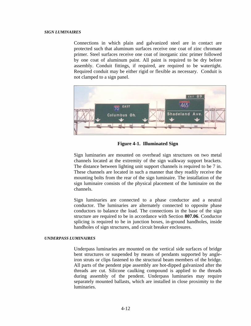
SIGN LUMINAIRES
Connections in which plain and galvanized steel are in contact are protected such that aluminum surfaces receive one coat of zinc chromate primer. Steel surfaces receive one coat of inorganic zinc primer followed by one coat of aluminum paint. All paint is required to be dry before assembly. Conduit fittings, if required, are required to be watertight. Required conduit may be either rigid or flexible as necessary. Conduit is not clamped to a sign panel.
Figure 4-1. Illuminated Sign
Sign luminaries are mounted on overhead sign structures on two metal channels located at the extremity of the sign walkway support brackets. The distance between lighting unit support channels is required to be 7 in. These channels are located in such a manner that they readily receive the mounting bolts from the rear of the sign luminaire. The installation of the sign luminaire consists of the physical placement of the luminaire on the channels. Sign luminaries are connected to a phase conductor and a neutral conductor. The luminaries are alternately connected to opposite phase conductors to balance the load. The connections in the base of the sign structure are required to be in accordance with Section 807.06. Conductor splicing is required to be in junction boxes, in-ground handholes, inside handholes of sign structures, and circuit breaker enclosures.
UNDERPASS LUMINAIRES
Underpass luminaries are mounted on the vertical side surfaces of bridge bent structures or suspended by means of pendants supported by angle-iron struts or clips fastened to the structural beam members of the bridge. All parts of the pendent pipe assembly are hot-dipped galvanized after the threads are cut. Silicone caulking compound is applied to the threads during assembly of the pendent. Underpass luminaries may require separately mounted ballasts, which are installed in close proximity to the luminaries.
4-13
Underpass luminaries are connected to a phase conductor and a neutral conductor. The luminaries are alternately connected to opposite phase conductors to balance the load. Conductor splicing is only allowed in junction boxes, in ground handholes, and circuit breaker enclosures.
HIGH MAST LUMINAIRES
The aiming of the luminaries is required to be as shown on the plans. When the aiming process is being done the luminaire is oriented to conform to the raised position and the ring properly tethered to prevent rotation during the aiming adjustment. The long axis of the luminaire is required to be parallel to the aiming direction indicated on the plans.
SIGN, UNDERPASS, ROADWAY, AND HIGH MAST LIGHTING LOCATION IDENTIFICATION
All high mast towers, roadway light standards, underpass lighting installations, and sign lighting installations is required to have an identification code number as shown on the plans. In addition, each luminaire at a sign or underpass installation is individually identified with a single capital letter. The code number is displayed on the light standard, sign structure column, and high mast tower as shown on the plans. The underpass code number is displayed near the breaker box at a location as directed. The code number for the lighting standard and sign structure column is applied to the pole, as specified by the manufacturer, by using individual, pressure sensitive, adhesive backed tags. The code number for the high mast tower is applied to an aluminum plate, which is mounted with spacers away from the structure as shown on the plans.
SERVICE POINT POWER ENTRY
The utility's requirements for service locations is required to be coordinated. Unless otherwise specified, a pole is furnished for the service point. If the utility requires metering of the lighting system, a meter socket is obtained from and installed in accordance with the requirements of the utility. Grounding is required to be in accordance with Section 807.11 and be a part of the service installation. Energy is required to be provided with 120/240 V service or 240/480 V service with the proper KW capacity on poles located immediately inside the right-of-way at locations designated on the plans. Electrical materials incorporated in the work are required to be compatible with the service voltages supplied by the local utility. The service voltages supplied by the local utility are checked for compliance with the planned voltages. If a discrepancy exists, a resolution is required as directed before work is started or any electrical equipment is purchased.
4-14
TYPES OF SERVICE POINTS
Service point installations are required to be of two types as shown on the plans.
1) Type I Service Point. This service point instillation consists
of class 5 wood pole, 2.75 in. galvanized steel conduits, weatherhead, photo cell and multiple relay switch. The conduit riser is fastened and supported on the pole by means of galvanized hook pipe straps and secured to the pole by means of a galvanized lag screw, all of the proper size for the conduit being installed. Cable-duct is installed in the conduit riser in accordance with Section 807.07. The conductors extend beyond the weatherhead a minimum of 4 ft. The conductors outside of the weatherhead are ringed to prevent moisture from entering the conduit enc1osure.
2) Type II Service Point. This service point installation
consists of a service cabinet with a single galvanized steel or aluminum conduit riser to the weatherhead. A multiple number of galvanized steel conduits extend from the bottom of the service cabinet in accordance with Section 807.05. Underground cable-duct is installed in accordance with Section 807.07(c). Connections, connectors, and fixtures are required to be as shown on the plans.
The service cabinet is secured to the pole by means of a galvanized steel channel post or other approved device.
SIGN AND UNDERPASS CIRCUITS
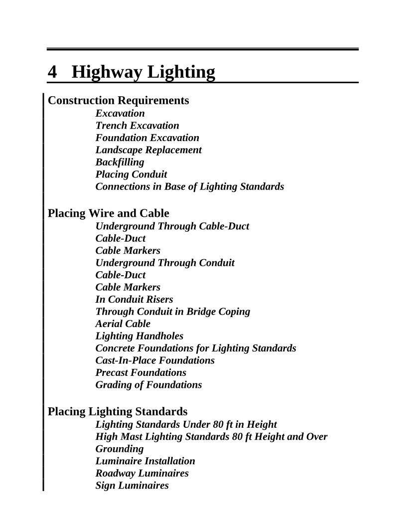
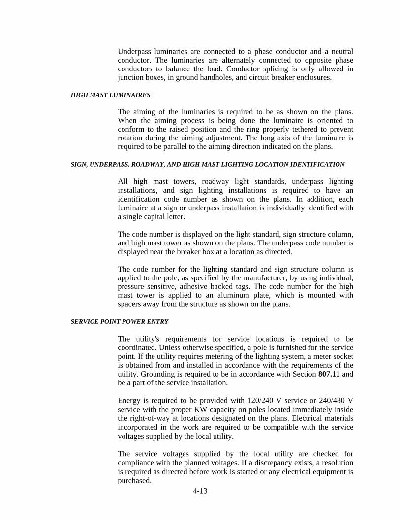
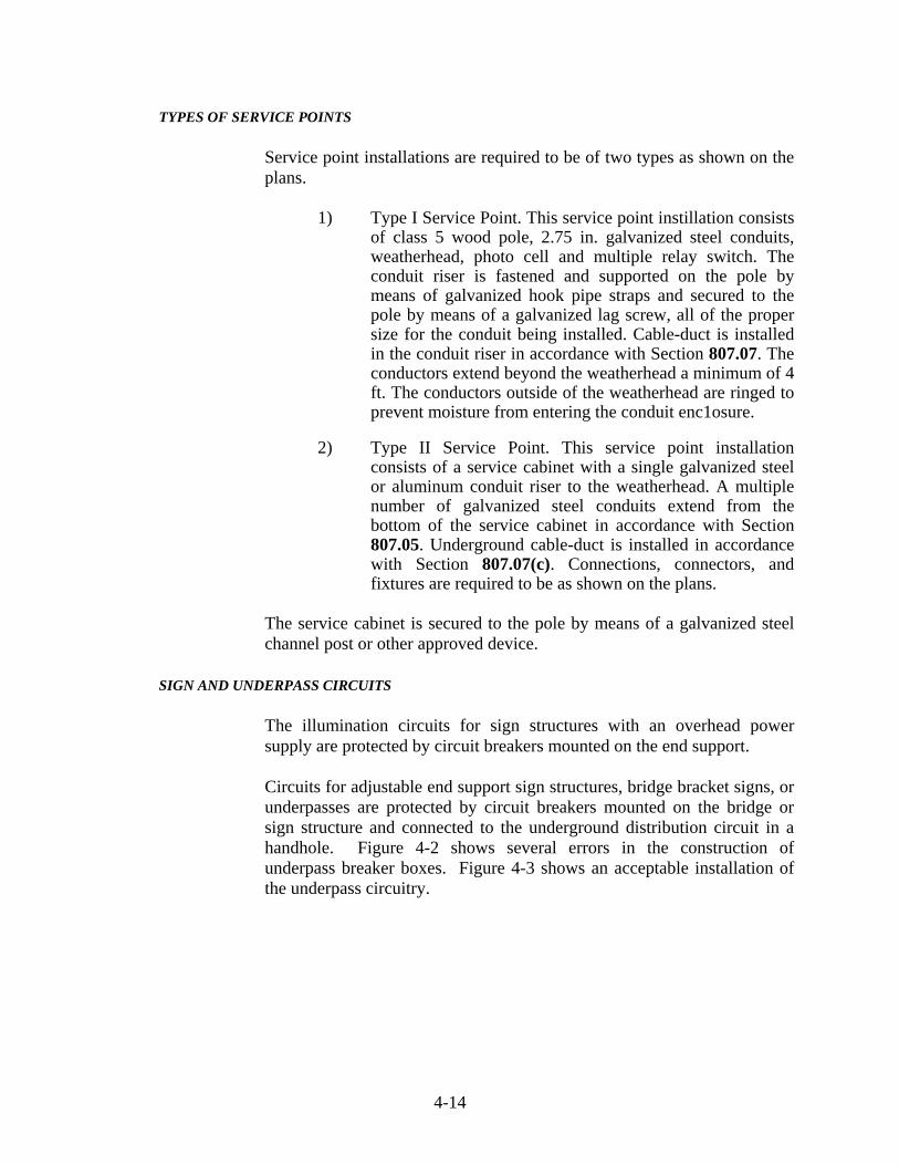
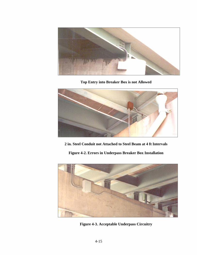
The illumination circuits for sign structures with an overhead power supply are protected by circuit breakers mounted on the end support. Circuits for adjustable end support sign structures, bridge bracket signs, or underpasses are protected by circuit breakers mounted on the bridge or sign structure and connected to the underground distribution circuit in a handhole. Figure 4-2 shows several errors in the construction of underpass breaker boxes. Figure 4-3 shows an acceptable installation of the underpass circuitry.
4-15
Top Entry into Breaker Box is not Allowed
2 in. Steel Conduit not Attached to Steel Beam at 4 ft Intervals
Figure 4-2. Errors in Underpass Breaker Box Installation
Figure 4-3. Acceptable Underpass Circuitry
4-16
Circuits for sign structures with an underground power supply are protected by fuse connector kits in the base of the sign support. The fuse connector kits include bayonet disconnect features for the "neutral" side and "hot" side.
MULTIPLE RELAY SWITCHES
Unless otherwise specified, wood pole, multiple relay switches, service cabinet, photocells, photocell receptacles, weatherhead, conduit, and other miscellaneous items are furnished and installed as a part of the service point.
TESTING OF HIGHWAY LIGHTING SYSTEM
TESTING LIGHTING CIRCUITRY
All necessary equipment and apparatus properly calibrated for testing the lighting circuits is required to be furnished. The supplying utility is given advance notice of the test scheduling so their representative may witness the testing procedures, if desired. Each main lighting circuit, including the branches, is tested for insulation resistance and continuity after completely installed but before the pole circuits, underpass circuits, sign circuits, and grounding circuits are connected. The insulation resistance test is made with a megohm meter and the resistance to ground is required to be no less than 50 megohms in all lighting circuit power cables. The meter is set for the voltage rating of the insulation. The continuity test is made with an ohmmeter properly scaled for measuring the resistance of the power cables. This test verifies the following:
1) That each power cable is continuous to the termination
points 2) That the cable coding at junction and termination points is
consistent with cable coding at the supply point
3) That power cables are not crossed with the neutral or each other
4) That the main circuit through each of the branches does not
have unusual resistance values
The entire completed installation is tested by circuit or by such portions as may be selected, and at night, if directed. Tests are required to demonstrate the following:
1) That all power, lighting, and control circuits are
continuous, free from short circuits, and free from unspecified grounds
4-17
2) That all circuits are properly connected in accordance with
applicable wiring diagrams 3) That all circuits are operable, which is demonstrated by
continuous operation of each lighting circuit for at least 1 h 4) That voltage at the ends of each lighting circuit and at inter
points is within allowable limits. A maximum of 10% voltage drop is permitted for each complete circuit.
TESTING AND INSPECTING LUMINAIRES
The lighting system from the service point through the last luminaire is subjected to 14 days of normal operation prior to final acceptance. This testing procedure may be conducted separately on each circuit or on the entire system. Normal operation is defined as the luminaires being on during the darkness hours and off during the daylight hours as controlled by the service point photocells and relay switches. Malfunctioning equipment is replaced or repaired before final inspection. The pattern of light delivered to the pavement by roadway and high mast luminaires is required to be inspected at night. At this inspection, the proper tools, equipment, and personnel are required to be available to make all adjustments. These items include a bucket truck capable of reaching all luminaires in the system, safety equipment, and a level to determine the proper luminaire position.
PAY ITEM AND INSTALLATION SUMMARY SHEETS
Prior to final inspection, two sets each of shop drawings, installation summary, and pay item summary marked Final Record are furnished for the light standards as installed. The installation summary shows the effective mounting height, arm length, foundation elevation, pay item, type of base, and catalog number or drawing for each light standard furnished. The pay item summary indicates the pay item, quantity, effective mounting height, arm length, and type of base for each type of lighting standard furnished.
METHOD OF MEASUREMENT
Luminaire, light standard with mast arm, high mast standard, identification number, connector kit, multiple compression fitting, insulating link, foundation, handhole, service point, and cable marker are required to be measured by the number of units installed. Pole circuit conductor and circuit conductor in conduit are measured by the linear foot. Pole circuit conductor is measured from the base of the lighting standard to the terminal block of the luminaire. Pole line extension is measured in a straight line between each pole.
4-18
Conductor in bridge conduit is measured by the linear foot from end to end of conduit or from the end of conduit to the last bridge light pole foundation entry. An allowance of 5 lft is made for each foundation entry. An allowance of 2 lft is made for each junction box. Removal of existing light structure, which includes the pole, mast arm, and foundation, is measured by the number of units removed. Cable-duct and conductor in underground duct or conduit is measured by the linear foot as follows:
1) From the Face of the Concrete Foundation to the Center of
the Handhole or Face of the Next Concrete Foundation: An allowance of 5 lft is made for each entry at foundations. An allowance of 2 lft is made at handholes for connection purposes.
2) From Lighting Standard Bases or Handholes to Switch
Boxes at Underpasses: An allowance of 4 lft is made at the switch box for electrical connections.
3) From End to End of the Conduit when the Cable is in
Conduit Under a Roadway Surface or Shoulder: No measurement is made of cable-duct in conduit where the cable-duct is part of a service point, sign installation, or Underpass lighting system.
4) Basis of Payment: Luminaire is paid for at the contract unit
price per each for the type and wattage specified. Service point is paid for at the contract unit price per each for the type specified. Light pole is paid for at the contract unit price per each for the estimated mounting height, length of mast arm, and base type specified.
Concrete lighting foundation with grounding is paid for at the contract unit price per each for the size specified. If class X material is encountered during lighting foundation excavation, payment is made for such excavation in accordance with Section 206. Partial payment for lighting foundation in the amount of 80% is made if all such work is complete except for finish grading and sodding. The remaining percentage of payment is made upon completion of the finish grading and sodding. Connector kit is paid for at the contract unit price per each for fused or unfused, as specified. Multiple compression fitting and insulation link are paid for at the contract unit price per each for waterproofed or nonwaterproofed, as specified.
Cable-duct marker, high mast tower winch drive, and handhole, lighting are paid for at the contract unit price per each. Sign, underpass, and
4-19
roadway lighting location identification are paid for at the contract unit price per each. Circuit installation is paid for at the contract unit price per each for the type, structure number, and number of luminaires specified. Removal of light structure and the portable tower lighting drive system are paid for at the contract unit price per each. Wire is paid for at the contract unit price per linear foot for the designation, copper gage, housing, and number of conductors specified. Pole circuit cable, THWH, stranded is paid for at the contract unit price per linear foot for the copper gage and number of conductors specified. Conduit, steel, galvanized, 2 in. diameter is paid for at the contract unit price per foot. The costs of lamps, ballast, optical systems, weatherproof housings, and e1ectrica1 connections are included in the cost of luminaire. The costs of the mast arm, J-support hook for pole circuit, handhole with cover, shoe base, transformer base or frangible coupling if required, installation on the foundation with the pole circuit, and luminaire installation are included in the cost of light pole. The costs of the pole, lowering system including winch assembly, power cable, support cable, concrete pad, luminaire ring, anchor bolts and nuts, lightning rod assembly, grounding system, and all incidental materials necessary to complete the installation are included in the cost of light pole, high mast. The costs of excavation, concrete, sleeves for cable duct, non-metal pipe, reinforcing steel, backfill, finish grading, and sodding are included in the cost of lighting foundation. The costs of aerial distribution service, drops to sign structures branching off from the pole line extension, weatherheads and risers required to connect the line extension to the underground electrical distribution circuit, all anchorage, guy wires, hardware, aerial cable, electrical connections, wood poles, and incidentals required to complete the pole line extension are included in the cost of cable, pole circuit.
The costs of snap-on covering in light pole base and waterproof covering in underground handhole is included in the cost of multiple compression fitting. The costs of circuit breakers, breaker enclosures, conduit, flexible conduit, conduit fittings, grounding, weatherhead, aerial cable termination, incidentals required from the last luminaire to the point of attachment by the utility, the bottom of the riser at the structure base, or the connector kits in the base of the sign supports are included in the cost of circuit installation. The cost of maintaining highway illumination during the contract time is included in the costs of other pay items.