Embed Size (px)
Citation preview
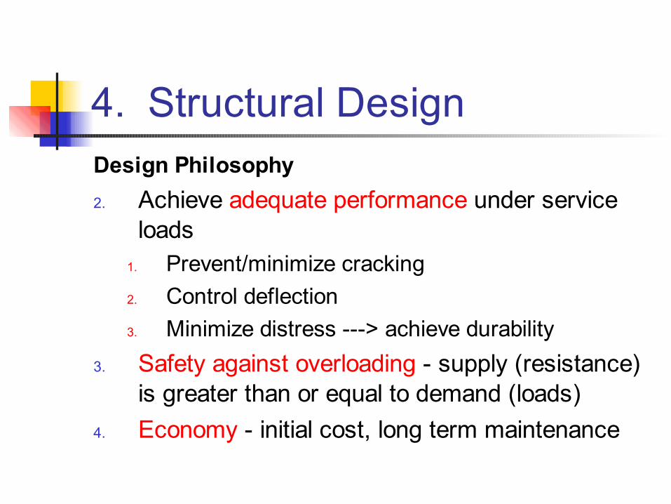
4. Structural DesignDesign Philosophy2. Achieve adequate performance under service
loads1. Prevent/minimize cracking2. Control deflection3. Minimize distress ---> achieve durability
3. Safety against overloading - supply (resistance) is greater than or equal to demand (loads)
4. Economy - initial cost, long term maintenance
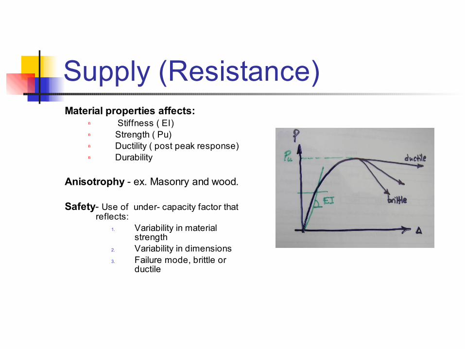
Supply (Resistance)Material properties affects:
n Stiffness ( EI)n Strength ( Pu)n Ductility ( post peak response)n Durability
Anisotrophy - ex. Masonry and wood.
Safety- Use of under- capacity factor that reflects:
1. Variability in material strength
2. Variability in dimensions3. Failure mode, brittle or
ductile
Resistance- Continue
Redundancy and indeterminacy - Provides alternate load paths and reduces the probability of collapse in case of overloading.
It also provides ample warning before collapse.
Non-structural components such as infill walls increase redundancy.
Loadbearing ( LB) Envelope Carries accumulated gravity and lateral
loads (critical at the base) Design LB building envelope as part of
the system (global) mainly for the in-plane action. In this case wall perforations will reduce stiffness and will increase lateral drift
Non-Loadbearing (NLB) Envelope NLB Envelope carries localized wind or earthquake
loads to the main system - mainly out of plane action ( produce moments) plus carrying self weight ( produces axial load)
Differential movement between the cladding (skin) and the backup main loadbearing system is a key design issue.
Focus in this course is on NLB envelope system - critical loads are: Out-of-Plane :
Localized wind (critical at top) Localized earthquake loads
In-Plane : Differential movement
Demand1. Applied loads (W,E)
Internal forces & deformation dependent on:n Load intensity -n Amount of differential movementn Geometry of paneln Boundary conditionn Material propertiesn X-section propertiesn Openings (doors and windows)
n Differential movement, due to:n Elastic deformation (depends on loads, geometry and E))n Creep ( concrete and concrete masonry)n Shrinkage ( concrete and concrete masonry)n Temperature ( all )n Moisture expansion ( clay)
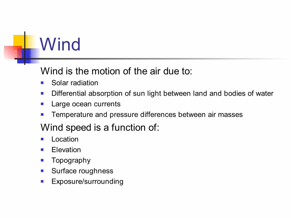
WindWind is the motion of the air due to: Solar radiation Differential absorption of sun light between land and bodies of water Large ocean currents Temperature and pressure differences between air masses
Wind speed is a function of: Location Elevation Topography Surface roughness Exposure/surrounding
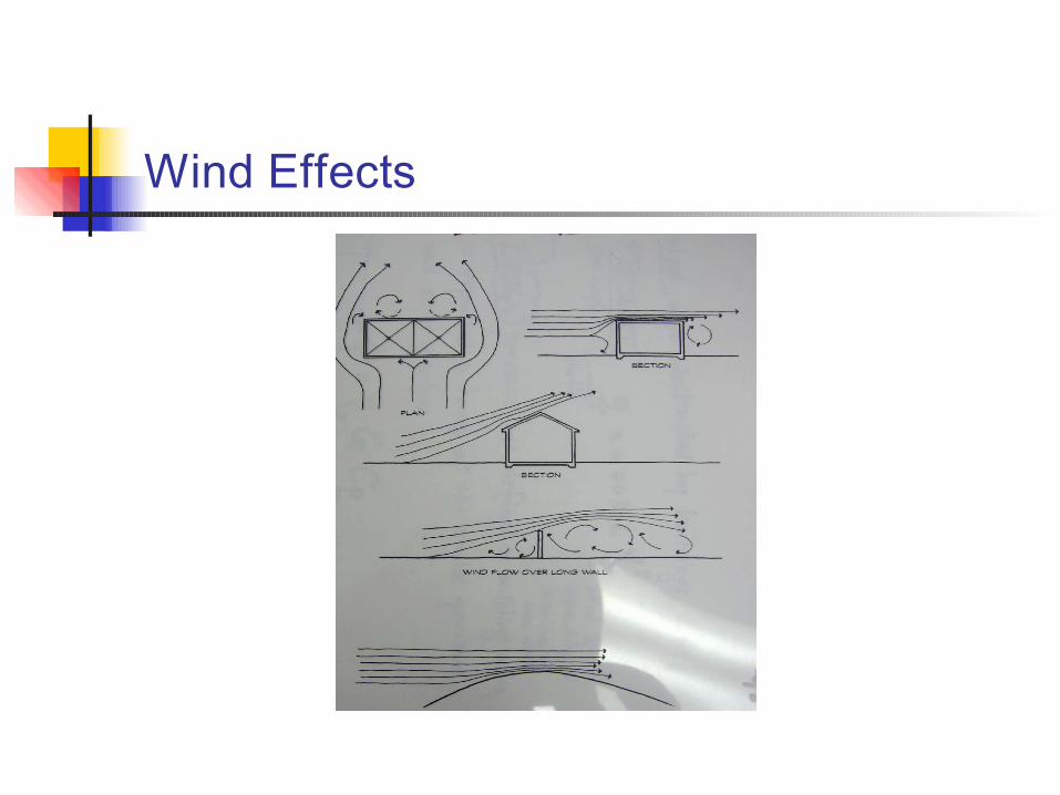
Wind Effects
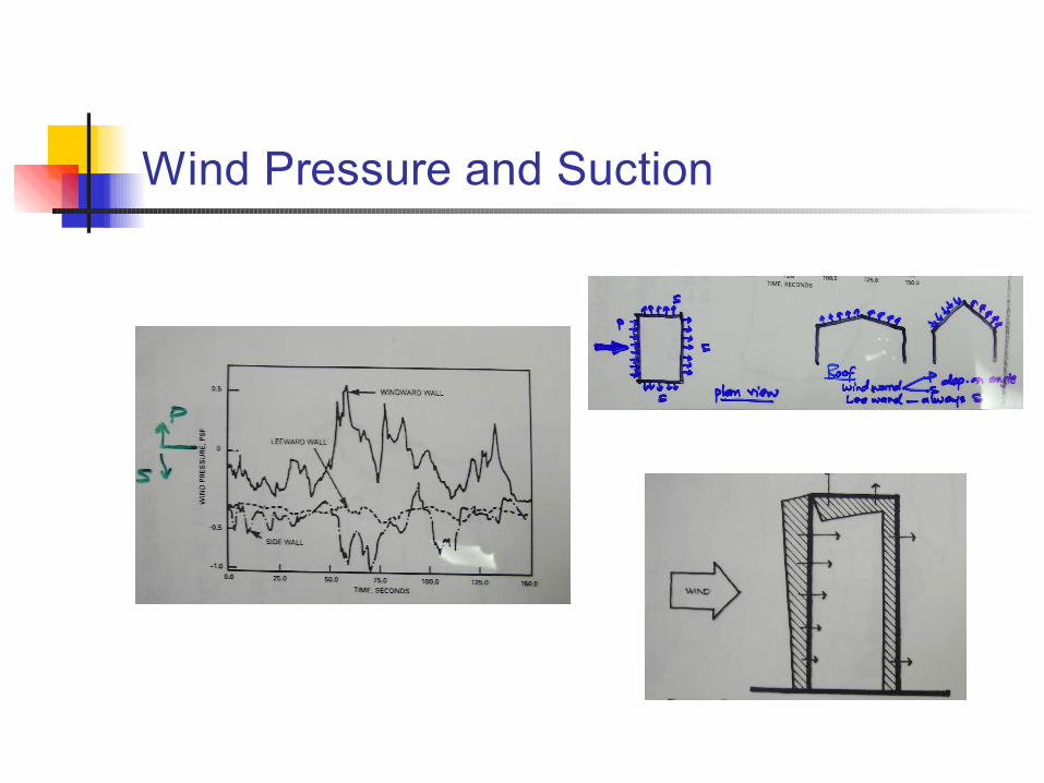
Wind Loads Velocity of air creates velocity pressure ( on
windward walls and roofs) and suction( on le3eward walls and roofs). This velocity pressure is modified to take into account other factors such as: Height Exposure condition Building geometryThe resulting pressure is the design pressure
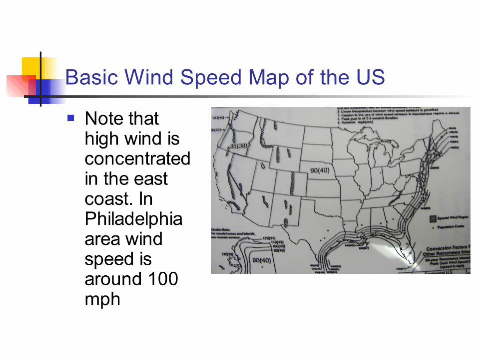
Basic Wind Speed Map of the US
Note that high wind is concentrated in the east coast. In Philadelphia area wind speed is around 100 mph
Wind Pressure
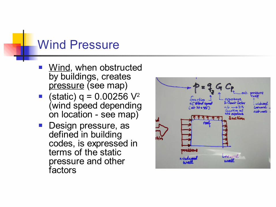
Wind, when obstructed by buildings, creates pressure (see map)
(static) q = 0.00256 V2 (wind speed depending on location - see map)
Design pressure, as defined in building codes, is expressed in terms of the static pressure and other factors
Wind Pressure and Suction
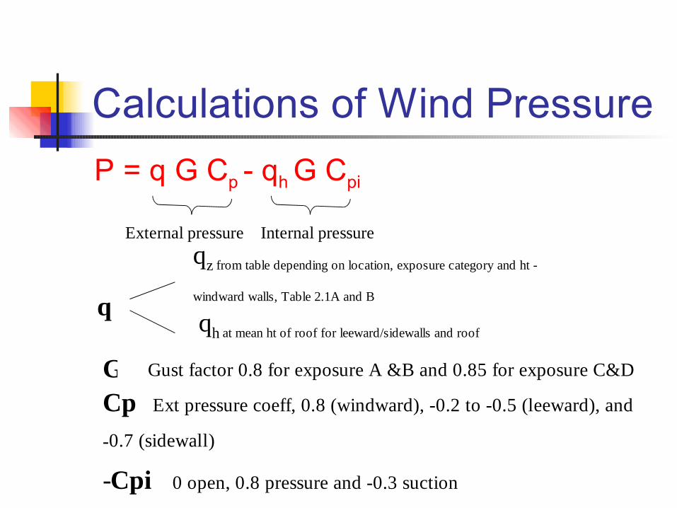
Calculations of Wind PressureP = q G Cp - qh G Cpi
External pressure Internal pressure
q
qz from table depending on location, exposure category and ht -
windward walls, Table 2.1A and B
qh at mean ht of roof for leeward/sidewalls and roof
G Gust factor 0.8 for exposure A &B and 0.85 for exposure C&D
Cp Ext pressure coeff, 0.8 (windward), -0.2 to -0.5 (leeward), and
-0.7 (sidewall)
-Cpi 0 open, 0.8 pressure and -0.3 suction
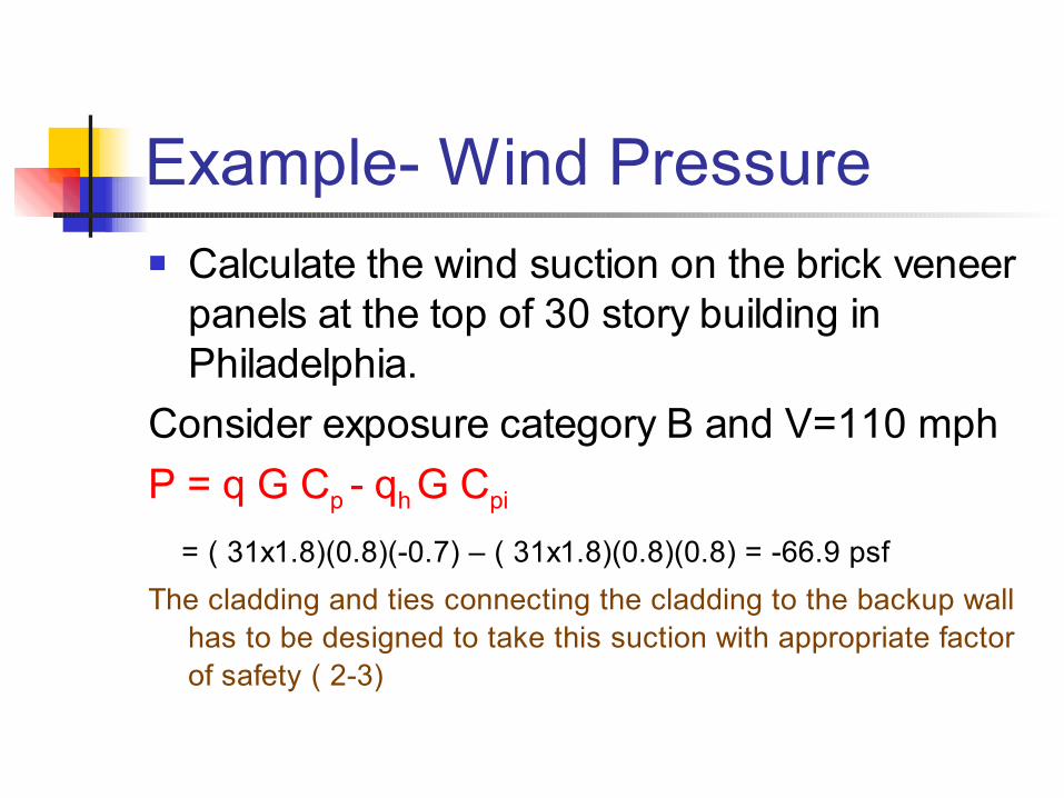
Example- Wind Pressure Calculate the wind suction on the brick veneer
panels at the top of 30 story building in Philadelphia.
Consider exposure category B and V=110 mphP = q G Cp - qh G Cpi
= ( 31x1.8)(0.8)(-0.7) – ( 31x1.8)(0.8)(0.8) = -66.9 psfThe cladding and ties connecting the cladding to the backup wall
has to be designed to take this suction with appropriate factor of safety ( 2-3)
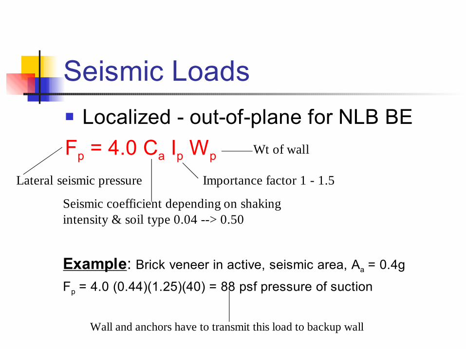
Seismic Loads Localized - out-of-plane for NLB BEFp = 4.0 Ca Ip Wp
Lateral seismic pressure
Seismic coefficient depending on shaking intensity & soil type 0.04 --> 0.50
Importance factor 1 - 1.5
Wt of wall
Example: Brick veneer in active, seismic area, Aa = 0.4g
Fp = 4.0 (0.44)(1.25)(40) = 88 psf pressure of suction
Wall and anchors have to transmit this load to backup wall
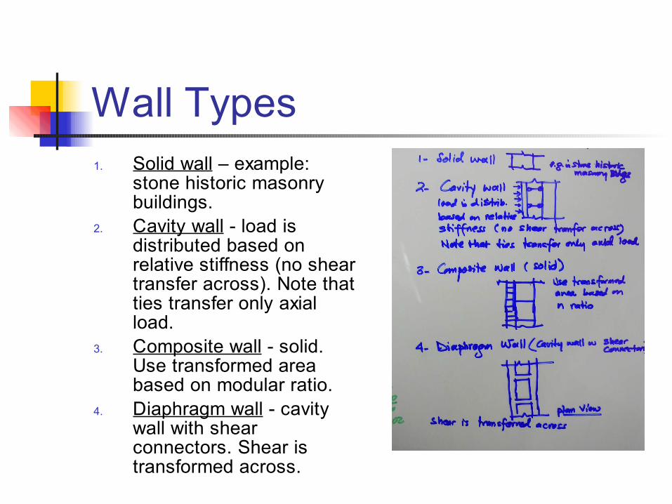
Wall Types1. Solid wall – example:
stone historic masonry buildings.
2. Cavity wall - load is distributed based on relative stiffness (no shear transfer across). Note that ties transfer only axial load.
3. Composite wall - solid. Use transformed area based on modular ratio.
4. Diaphragm wall - cavity wall with shear connectors. Shear is transformed across.
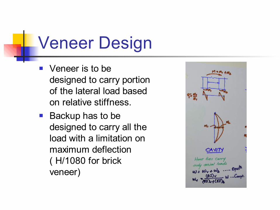
Veneer Design Veneer is to be
designed to carry portion of the lateral load based on relative stiffness.
Backup has to be designed to carry all the load with a limitation on maximum deflection ( H/1080 for brick veneer)
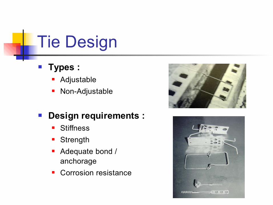
Tie Design Types :
Adjustable Non-Adjustable
Design requirements : Stiffness Strength Adequate bond /
anchorage Corrosion resistance
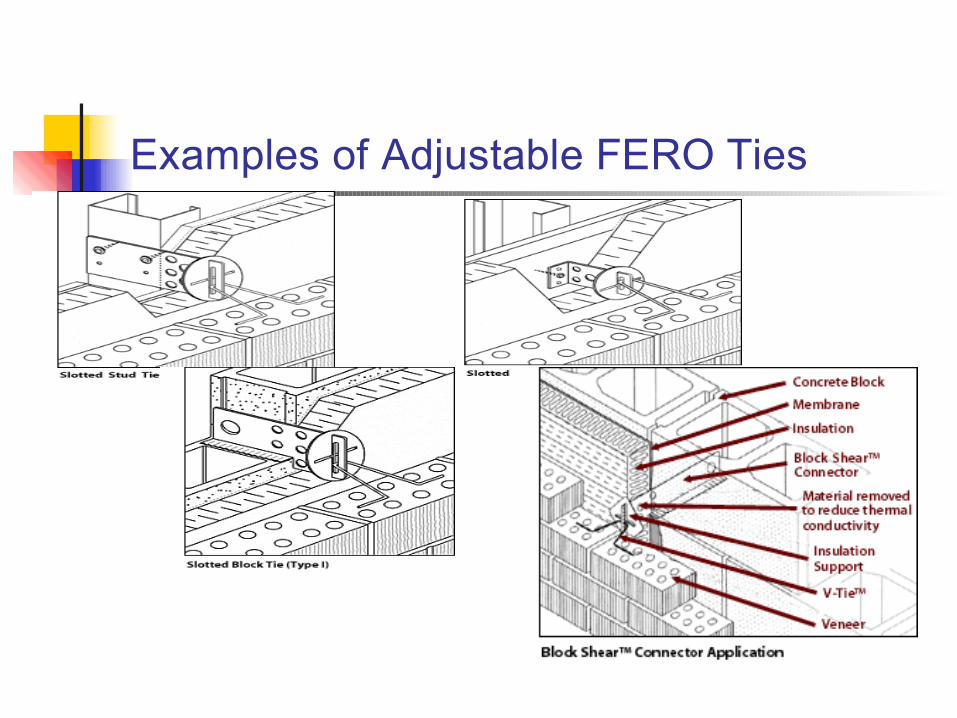
Examples of Adjustable FERO Ties
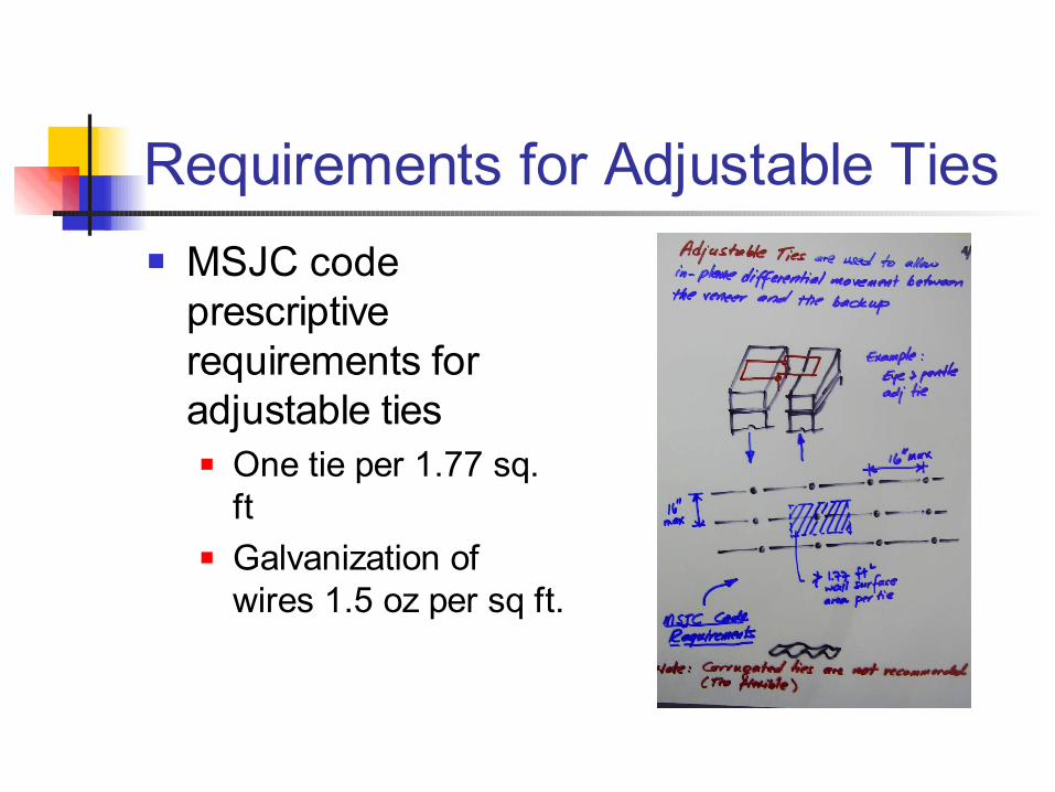
Requirements for Adjustable Ties MSJC code
prescriptive requirements for adjustable ties One tie per 1.77 sq.
ft Galvanization of
wires 1.5 oz per sq ft.
Shelf Angle Design Typical steel angle
anchored to the spandrel beam at 4’ spacing
Carries wt of veneer. Vertical load produces torsion on the angle and combined shear and tension on the anchor bolts
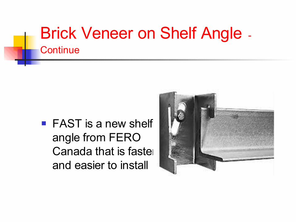
Brick Veneer on Shelf Angle - Continue
FAST is a new shelf angle from FERO Canada that is faster and easier to install
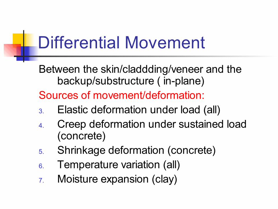
Differential MovementBetween the skin/claddding/veneer and the
backup/substructure ( in-plane)Sources of movement/deformation:3. Elastic deformation under load (all)4. Creep deformation under sustained load
(concrete)5. Shrinkage deformation (concrete)6. Temperature variation (all)7. Moisture expansion (clay)
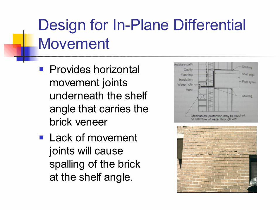
Design for In-Plane Differential Movement Provides horizontal
movement joints underneath the shelf angle that carries the brick veneer
Lack of movement joints will cause spalling of the brick at the shelf angle.
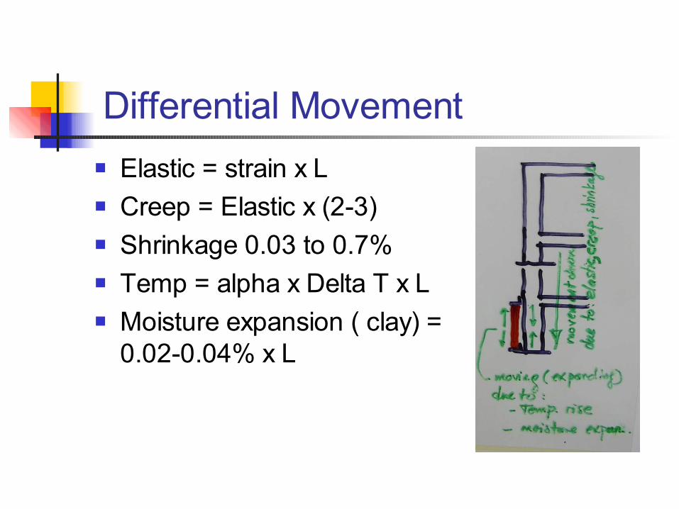
Differential Movement Elastic = strain x L Creep = Elastic x (2-3) Shrinkage 0.03 to 0.7% Temp = alpha x Delta T x L Moisture expansion ( clay) =
0.02-0.04% x L
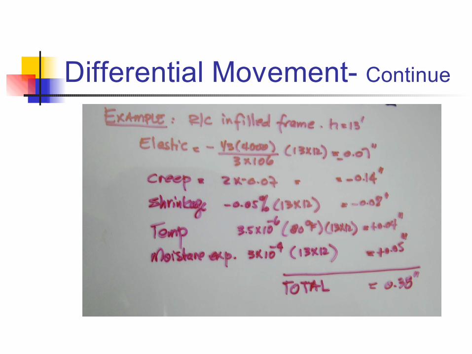
Differential Movement- Continue