Embed Size (px)
Citation preview
4.1 lithology, Stratigraphy, and Structure
The nature and distribution of aquifers and aquitards in a geologic system are controlled by the lithology, stratigraphy, and structure of the geologic deposits and formations. The lithology is the physical makeup, including the mineral composition, grain size, and grain packing, of the sediments or rocks that make up the geological systems. The stratigraphy describes the geometrical and age relations between the various lenses, beds, and formations in geologic systems of sedimentary origin. Structural features, such as cleavages, fractures, folds, and faults are the geometrical properties of the geologic systems produced by deformation after deposition or crystallization. In unconsolidated deposits, the lithology and stratigraphy constitute the most important controls. In most regions knowledge of the lithology, stratigraphy, and structure leads directly to an understanding of the distribution of aquifers and aquitards.
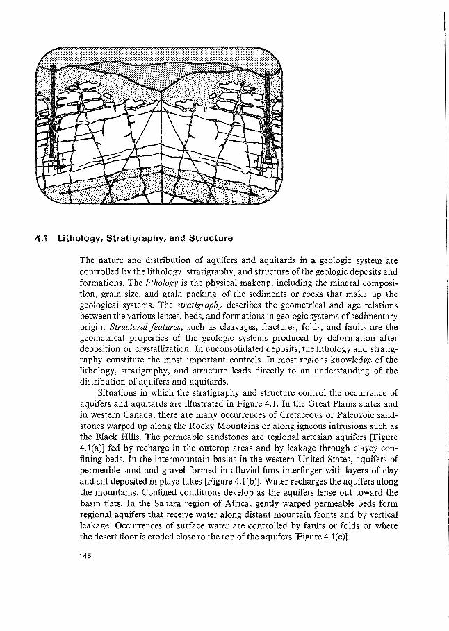
Situations in which the stratigraphy and structure control the occurrence of aquifers and aquitards are illustrated in Figure 4.1. In the Great Plains states and in western Canada, there are many occurrences of Cretaceous or Paleozoic sandstones warped up along the Rocky Mountains or along igneous intrusions such as the Black Hills. The permeable sandstones are regional artesian aquifers [Figure 4. l(a)] fed by recharge in the outcrop areas and by leakage through clayey confining beds. In the intermountain basins in the western United States, aquifers of permeable sand and gravel formed in alluvial fans interfinger with layers of clay and silt deposited in playa lakes [Figure 4.l(b)]. Water recharges the aquifers along the mountains. Confined conditions develop as the aquifers lense out toward the basin flats. In the Sahara region of Africa, gently warped permeable beds form regional aquifers that receive water along distant mountain fronts and by vertical leakage. Occurrences of surface water are controlled by faults or folds or where the desert floor is eroded close to the top of the aquifers [Figure 4.l(c)].
145
146 Groundwater Geology I Ch. 4
Figure 4.1 Influence of stratigraphy and structure on regional aquifer occurrence. (a) Gently dipping sandstone aquifers with outcrop area along mountain front; (b) interfingering sand and gravel aquifers extending from uplands in intermountain region; (c) faulted and folded aquifer in desert region. Surface water bodies reflect structural features (after Hamblin, 1976).
Unconformities are stratigraphic features of particular importance in hydrogeology. An unconformity is a surface that represents an interval of time during which deposition was negligible or nonexistent, or more commonly during which the surface of the existing rocks was weathered, eroded, or fractured. Often the underlying rocks were warped or tilted prior to the deposition of new materials over the unconformity. Aquifers are commonly associate9. with unconformities, either in the weathered or fractured zone immediately befow the surface of the buried landscape or in permeable zones in coarse-grained sediments laid down on top of this surface when the system entered a new era of accretion. In many of the tectonically stable parts of the interior of North America, where near-horizontal sedimentary rocks occur beneath the overburden, the occurrence of unconformities
147 Groundwater Geology / Ch. 4
are the key to the distribution of aquifers and aquitards and the quality of water within them.
In terrain that has been deformed by folding and faulting, aquifers can be difficult to discern because of the geologic complexity. In these situations the main ingredient in groundwater investigations is often large-scale structural analysis of the geologic setting.
4.2 Fluvial Deposits
Nonindurated deposits are composed of particles of gravel, sand, silt, or clay size that are not bound or hardened by mineral cement, by pressure, or by thermal alteration of the grains. Fluvial deposits are the materials laid down by physical processes in river channels or on floodplains. The materials are also known as alluvial deposits. In this section emphasis is on fluvial materials deposited in nonglacial environments. Deposits formed by meltwater rivers are discussed in Section 4.4.
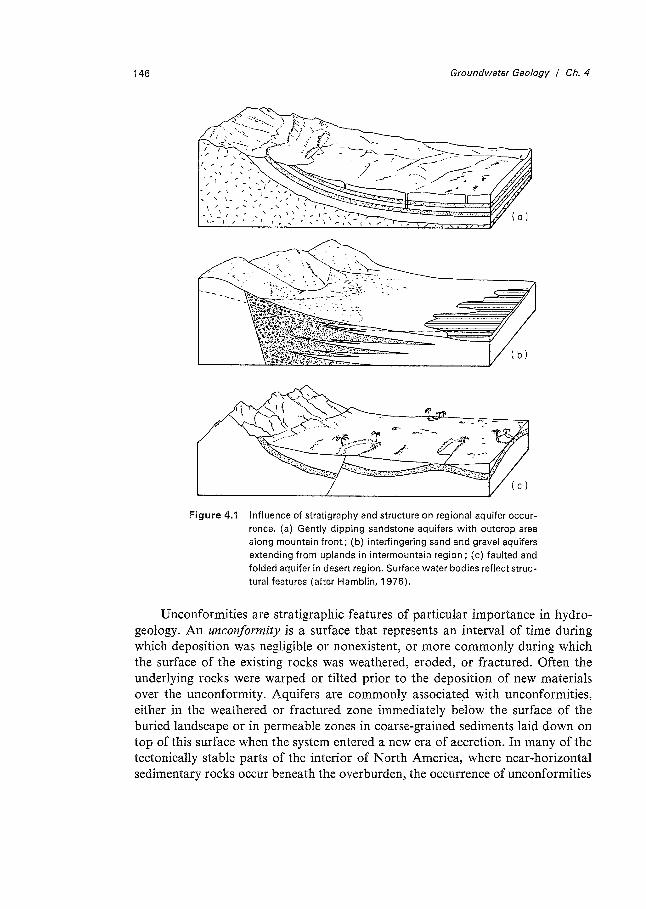
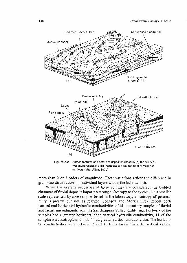
Flu vial materials occur in nearly all regions. In many areas aquifers of fluvial origin are important sources of water supply. Figure 4.2 illustrates the morphology and variations in deposits formed by braided rivers and by meandering rivers. Because of the shifting position of river channels and the ever-changing depositional velocities, river deposits have characteristic textural variability that causes much heterogeneity in the distribution of hydraulic properties. Braided rivers generally occur in settings where the sediment available for transport has considerable coarse-grained sand or gravel and where velocities are large because of steep regional topographic slopes. Shifting positions of channels and bars and changing velocity can result in extensive deposits of bedded sand and gravel with minor zones of silty or clayey sediments filling in abandoned channels. Meandering rivers and their associated floodplain environments also have coarse and fine-grained deposits. The relative abundances and stratigraphic relations of the sediments, however, are generally much different than in braided-river deposits. Silty or clayey channel-fill deposits are more abundant than in braided-river deposits. Cross-bedded sand, which is commonly fine- or medium-grained with variable contents of silt and clay, is deposited on the levees and floodplains. Coarse sand and gravel commonly form along point bars. Gravel deposits develop as channel lag. The relative abundance of the various deposits laid down in meandering rivers and their floodplains are greatly influenced by the nature of the sediments supplied to the river from the watershed. Because of the variability of sediment sources and flow, delineation of aquifer zones in these deposits using borehole data is a difficult task that often involves much speculation.
Large numbers of hydraulic conductivity tests, both in the field and in the laboratory, have been made on fluival deposits. Results of permeameter tests on core samples characteristically indicate variations within the permeable zones of
148 Groundwater Geology I Ch. 4
Cut-off channel
Levee
( b)
Figure 4.2 Surface features and nature of deposits formed in (a) the braidedriver environment and (b) the floodplain environment of meandering rivers (after Allen, 1970).
more than 2 or 3 orders of magnitude. These variations reflect the difference in grain-size distributions in individual layers within the bulk deposit.
When the average properties of large volumes are considered, the bedded character offluvial deposits imparts a strong anisotropy to the system. On a smaller scale represented by core samples tested in the laboratory, anisotropy of permeability is present but not as marked. Johnson and Morris (1962) report both vertical and horizontal hydraulic conductivities of 61 laboratory samples of fluvial and lacustrine sediments from the San Joaquim Valley, California. Forty-six of the samples had a greater horizontal than vertical hydraulic conductivity, 11 of the samples were isotropic and only 4 had greater vertical conductivities. The horizontal conductivities were between 2 and 10 times larger than the vertical values.
4.3 Aeolian Deposits
Materials that are transported and deposited by wind are known as aeolian deposits. Aeolian deposits consist of sand or silt. Sand dunes form along coasts and in inland areas where rainfall is sparse and surface sand is available for transportation and deposition. Nonindurated aeolian sand is characterized by lack of silt and clay fractions, by uniform texture with particles in the fine- or medium-grain-size range, and by rounded grains. These sands are moderately permeable (10-4-10- 6
m/s) and form aquifers in areas where appreciable saturated thicknesses occur. Porosities are between 30 and 45 %. In comparison with alluvial deposits, aeolian sands are quite homogeneous and are about as isotropic as any deposits occurring in nature. The sorting action of wind tends to produce deposits that are uniform on a local scale and in some cases quite uniform over large areas.
The most extensive nonindurated aeolian deposits in North America are blanket deposits of silt, which are known as loess. Loess occurs at the surface or in the shallow subsurface in large areas in the Midwest and Great Plains regions of North America. Loess was deposited during Pleistocene and post-Pleistocene time as a result of wind activity that caused clouds of silt to be swept across the landscape. Because of small amounts of clay and calcium carbonate cement that are almost always present, loess is slightly to moderately cohesive. The porosity of loess is normally in the range 40-50 %. Hydraulic conductivity varies from about 10-s m/s for coarse, clean loess to l0- 7 m/s or lower in fine or slightly clayey loess that has no secondary permeability.
Fractures, root channels, and animal burrows commonly cause secondary permeability in the vertical direction that may greatly exceed the primary permeability. As a result of repeated episodes of atmospheric silt movement, buried soils are common in loess. Zones of secondary permeability are often associated with these soils. In some loess areas sufficient permeability occurs at depth to provide farm or household water supplies. Major aquifers, however, do not occur in loess. In some situations blankets of loess act as aquitards overlying major aquifers. For further information on the occurrence and hydraulic properties of loess, the reader is referred to Gibbs and Holland (1960) and McGary and Lambert (1962).
4.4 Glacial Deposits
Of particular hydrogeologic importance in the northern part of the United States and in Canada and Europe are deposits formed by or in association with continental glaciers. The deposits include glacial till, glaciofluvial sediments, and glaciolacustrine sediments. In meltwater lakes that existed during Pleistocene time, deposits of glaciolacustrine silt and clay were laid down offshore. These deposits form some of the most extensive shallow aquitards in North America. Sand and gravel deposits laid down near shore and on beaches are aquifers in
149
150 Groundwater Geology I Ch. 4
some areas. In comparison to aquifers of glaciofluvial origin, these aquifers of glaciolacustrine origin are generally of minor importance.
Glacial till is the most abundant material that was deposited on the land surface during Pleistocene time. In the Precambrian Shield region, till is generally sandy, with variable amounts of silt and little clay. Sandy till forms local aquifers in some areas. In the regions of sedimentary bedrock in North America, glacial erosion produced till that generally has considerable silt and clay and therefore has low permeability. Till layers of this type are aquitards.
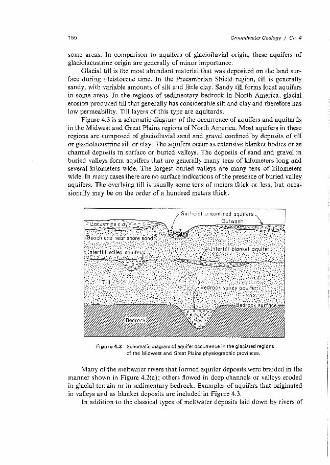
Figure 4.3 is a schematic diagram of the occurrence of aquifers and aquitards in the Midwest and Great Plains regions of North America. Most aquifers in these regions are composed of glaciofluvial sand and gravel confined by deposits of till or glaciolacustrine silt or clay. The aquifers occur as extensive blanket bodies or as channel deposits in surface or buried valleys. The deposits of sand and gravel in buried valleys form aquifers that are generally many tens of kilometers long and several kilometers wide. The largest buried valleys are many tens of kilometers wide. In many cases there are no surface indications of the presence of buried valley aquifers. The overlying till is usually some tens of meters thick or less, but occasionally may be on the order of a hundred meters thick.
Figure 4.3 Schematic diagram of aquifer occurrence in the glaciated regions of the Midwest and Great Plains physiographic provinces.
Many of the meltwater rivers that formed aquifer deposits were braided in the manner shown in Figure 4.2(a); others flowed in deep channels or valleys eroded in glacial terrain or in sedimentary bedrock. Examples of aquifers that originated in valleys and as blanket deposits are included in Figure 4.3.
In addition to the classical types of meltwater deposits laid down by rivers of
151 Groundwater Geology I Ch. 4
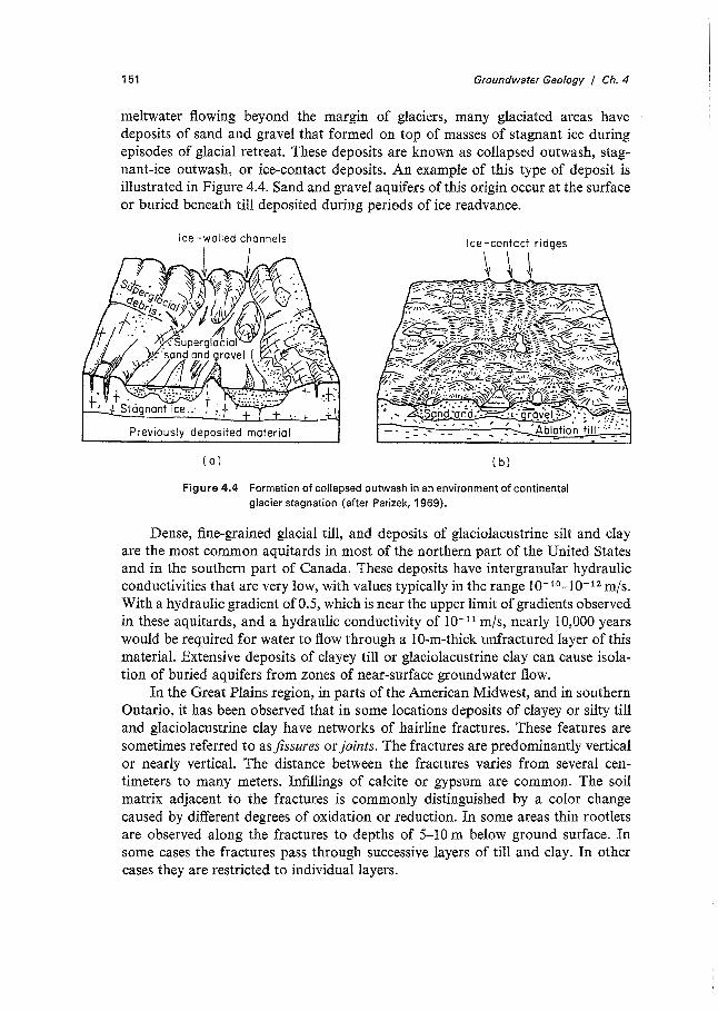
meltwater flowing beyond the margin of glaciers, many glaciated areas have deposits of sand and gravel that formed on top of masses of stagnant ice during episodes of glacial retreat. These deposits are known as collapsed outwash, stagnant-ice outwash, or ice-contact deposits. An example of this type of deposit is illustrated in Figure 4.4. Sand and gravel aquifers of this origin occur at the surface or buried beneath till deposited dudng periods of ice readvance.
Previously deposited material
{a) { b)
Figure 4.4 Formation of collapsed outwash in an environment of continental glacier stagnation (after Parizek, 1969).
Dense, fine-grained glacial till, and deposits of glaciolacustrine silt and clay are the most common aquitards in most of the northern part of the United States and in the southern part of Canada. These deposits have intergranular hydraulic conductivities that are very low, with values typically in the range 10- 10-10- 12 m/s. With a hydraulic gradient of0.5, which is near the upper limit of gradients observed in these aquitards, and a hydraulic conductivity of 10- 11 m/s, nearly 10,000 years would be required for water to flow through a 10-m-thick unfractured layer of this material. Extensive deposits of clayey till or glaciolacustrine clay can cause isolation of buried aquifers from zones of near-surface groundwater flow.
In the Great Plains region, in parts of the American Midwest, and in southern Ontario, it has been observed that in some locations deposits of clayey or silty till and glaciolacustrine clay have networks of hairline fractures. These features are sometimes referred to as fissures or joints. The fractures are predominantly vertical or nearly vertical. The distance between the fractures varies from several centimeters to many meters. Infillings of calcite or gypsum are common. The soil matrix adjacent to the fractures is commonly distinguished by a color change caused by different degrees of oxidation or reduction. In some areas thin rootlets are observed along the fractures to depths of 5-10 m below ground surface. In some cases the fractures pass through successive layers of till and clay. In other cases they are restricted to individual layers.
152 Groundwater Geology I Ch. 4
In many areas the fractures impart an enhanced capability for groundwater flow. The bulk hydraulic conductivity of the fractured till and clay determined by field tests is commonly between 1 and 3 orders of magnitude larger than values of intergranular hydraulic conductivity determined by laboratory tests on unfractured samples. As a result of increased lateral stresses caused by overburden loading, the hydraulic conductivity of fractured till and clay decreases with depth, but because of the stiffness of many of these materials the fractures can provide significant secondary permeability to depths of hundreds of meters.
In areas of glacial till and glaciolacustrine clay, highly fractured zones are common within several meters of the ground surface. Shallow fractures are caused primarily by stress changes resulting from cycles of wetting and drying and freezing and thawing. Openings caused by roots also cause secondary permeability. The origin of fracture networks at greater depths is more problematic. Mechanisms such as stress release related to glacial unloading and crustal rebound, and volume changes due to geochemical processes such as cation exchange, have been suggested by various investigators. For more detailed discussions of the nature and hydrogeologic significance of fractures in till and glaciolacustrine clay, the reader is referred to Rowe (1972), Williams and Farvolden (1969), Grisak and Cherry (1975) and Grisak et al. (1976).
4.5 Sedimentary Rocks
Sandstone
About 25 % of the sedimentary rock of the world is sandstone. In many countries sandstone strata form regional aquifers that have vast quantities of potable water. Sandstone bodies of major hydrologic significance owe their origin to various depositional environments, including floodplain, marine shoreline, deltaic, aeolian, and turbidity-current environments. Knowledge of the distribution of permeability in sandstones can best be acquired within an interpretive framework that is based on an understanding of depositional environments in which the sand bodies were formed. In this endeavor a knowledge of sedimentology is necessary. The monograph by Blatt et al. (1972) provides a comprehensive discussion of the origin and character of sandstone.
Nonindurated sands have porosities in the range 30-50 %· Sandstones, however, commonly have lower porosities because of compaction and because of cementing material between the grains. In extreme cases porosities are less than 1 % and hydraulic conductivities approach those o.f unfractured siltstone and shale (i.e., less than about 10- 10 m/s). The most common cementing materials are quartz, calcite, and clay minerals. These minerals form as a result of precipitation or mineral alteration during groundwater circulation through the sand. Compaction is important at great depth, where temperatures and pressures are high. Studies by Chilingar (1963), Maxwell (1964), and Atwater (1966) show that the porosity of sandstone decreases systematically with depth. In Louisiana petroleum
153 Groundwater Geology I Ch. 4
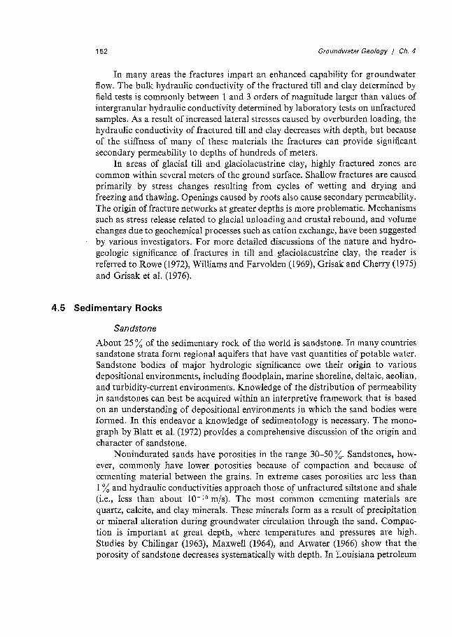
reservoirs, Atwater found that the decrease averages about 1.3 % for every 300-m increase in depth of burial. Chilingar (1963) showed that when sand and sandstone are grouped according to grain-size categories, there are well-defined trends of increasing permeability with increasing porosity (Figure 4.5). An increase in porosity of several percent corresponds to a large increase in permeability.
10000
6000 4000
2000
1000 VJ 600 >-~ 400 0
"'O
.E 200
>- 100
:0 60 0 40 Q.l
E Q) 20 o_
iO
6 4
2
1
I
• 0 4 8 12 16 20
Porosity (%)
o Coarse - and very coarse-grained
•Coarse- and medium-grained
a Fine-grained
a Silty
11 Clayey
24 28 32
Figure 4.5 Relationship between porosity and permeability for sandstone in various grain-size categories (after Chilingar, 1963).
36
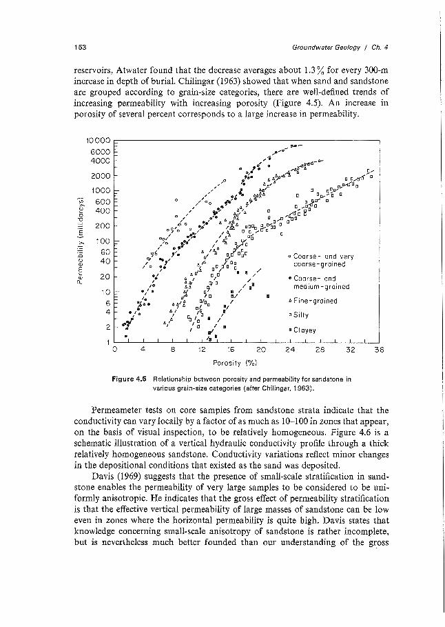
Permeameter tests on core samples from sandstone strata indicate that the conductivity can vary locally by a factor of as much as 10-100 in zones that appear, on the basis of visual inspection, to be relatively homogeneous. Figure 4.6 is a schematic illustration of a vertical hydraulic conductivity profile through a thick relatively homogeneous sandstone. Conductivity variations reflect minor changes in the depositional conditions that existed as the sand was deposited.
Davis (1969) suggests that the presence of small-scale stratification in sandstone enables the permeability of very large samples to be considered to be uniformly anisotropic. He indicates that the gross effect of permeability stratification is that the effective vertical permeability of large masses of sandstone can be low even in zones where the horizontal permeability is quite high. Davis states that knowledge concerning small-scale anisotropy of sandstone is rather incomplete, but is nevertheless much better founded than our understanding of the gross
154
Q)
0 ..c (f)
~
..
Q) .. c 0 Vi -0 c 0
Cf)
..
Q) c 0 Vi Q)
-~ _J
,. E ..c a. Q)
0
t .. . .
0
100 10-4
Groundwater Geology I Ch. 4
Hy drau I ic conductivity
10-6
m/s
Figure 4.6 Schematic diagram of hydraulic conductivity versus depth relation for a thick, relatively homogeneous sandstone aquifer.
anisotropy of large volumes. Based on hydraulic conductivity measurements of a large number of core samples, Piersol et al. (1940) observed a mean ratio of the horizontal to vertical conductivity of 1.5. Only 12 % of the samples had ratios above 3.0.
As sands become more cemented and compacted (i.e., more lithified) the contribution of fractures to the bulk permeability of the material increases. The tendency of large permeability values to occur in the horizontal direction is replaced by a preference for higher fracture permeability in the vertical direction. The nature of the anistropy in the fractured medium can reflect a complex geological history involving many stress cycles.
Carbonate Rock
Carbonate rocks, in the form of limestone and dolomite, consist mostly of the minerals calcite and dolomite, with very minor amounts of clay. Some authors refer to dolomitic rock as dolostone. In this text, dolomite is used to denote both the mineral and the rock. Nearly all dolomite is secondary in origin, formed by geochemical alteration of calcite. This mineralogical transformation causes an increase in porosity and permeability because the crystal lattice of dolomite occupies about 13 % less space than that of calcite. Geologically young carbonate
155 Groundwater Geology I Ch. 4
rocks commonly have porosities that range from 20 % for coarse, blocky limestone to more than 50 % for poorly indurated chalk (Davis, 1969). With increasing depth of burial, the matrix of soft carbonate minerals is normally compressed and recrystallized into a more dense, less porous rock mass. The primary permeability of old unfractured limestone and dolomite is commonly less than 10-7 m/s at nearsurface temperature. Carbonate rocks with primary permeability of this magnitude can be important in the production of petroleum but are not significant sources of groundwater supply.
Many carbonate strata have appreciable secondary permeability as a result of fractures or openings along bedding planes. Secondary openings in carbonate rock caused by changes in the stress conditions may be enlarged as a result of calcite or dolomite dissolution by circulating groundwater. For the water to cause enlargement of the permeability network, it must be undersaturated with respect to these minerals. The origin of solution openings in carbonate rock is described in Chapter 11.
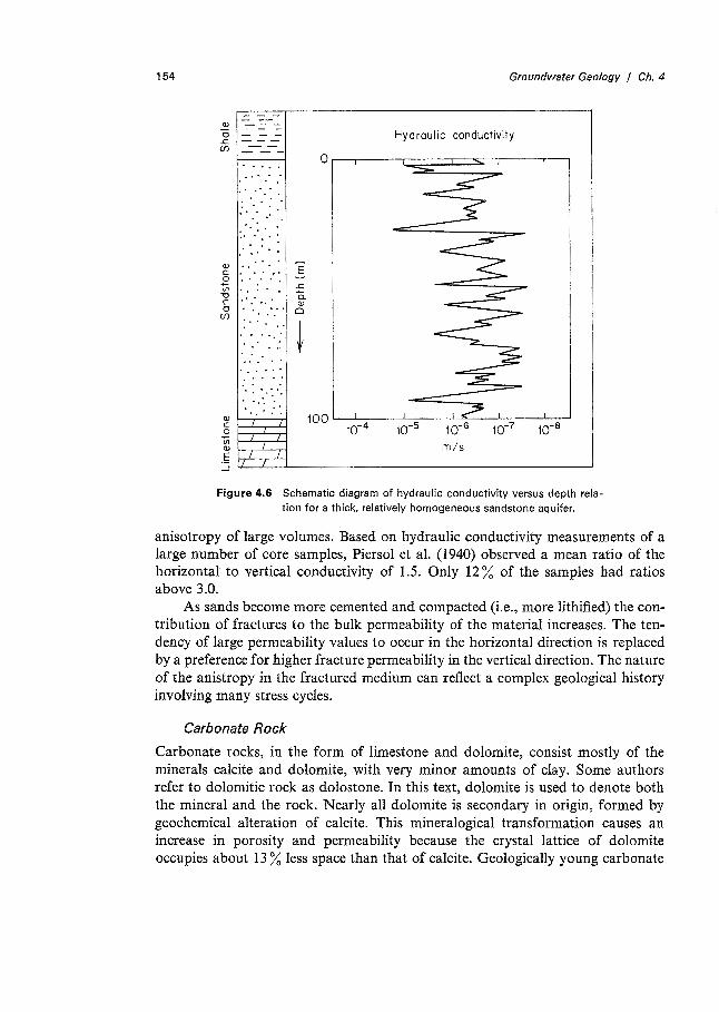
Observations in quarries and other excavations in flat-lying carbonate rocks indicate that solution openings along vertical joints generally are widely spaced. Openings along bedding planes are more important from the point of view of water yield from wells (Walker, 1956; Johnston, 1962). In nearly horizontal carbonate rocks with regular vertical fractures and horizontal bedding planes, there is usually a much higher probability of wells encountering horizontal openings than vertical fractures. This is illustrated in Figure 4.7. In fractured carbonate rocks, successful and unsuccessful wells can exist in close proximity, depending on the frequency of encounter of fractures by the well bore. Seasonally, the water
Soil and clay Local artesian pressure raises water above surface)
Figure 4.7 Schematic illustration of the occurrence of groundwater in carbonate rock in which secondary permeability occurs along enlarged fractures and bedding plane openings (after Walker, 1956; Davis and De Wiest, 1966).
156 Groundwater Geology / Ch. 4
levels in shallow wells can vary greatly because the bulk fracture porosity is generally a few percent or less.
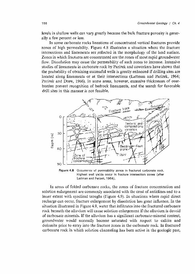
In some carbonate rocks lineations of concentrated vertical fractures provide zones of high permeability. Figure 4.8 illustrates a situation where the fracture intersections and lineaments are _reflected in the morphology of the land surface. Zones in which fractures are concentrated are the zones of most rapid groundwater fl.ow. Dissolution may cause the permeability of such zones to increase. Intensive studies of lineaments in carbonate rock by Parizek and coworkers have shown that the probability of obtaining successful wells is greatly enhanced if drilling sites are located along lineaments or at their intersections (Lattman and Parizek, 1964; Parizek and Drew, 1966). In some areas, however, excessive thicknesses of overburden prevent recognition of bedrock lineaments, and the search for favorable drill sites in this manner is not feasible.
'E .s:: a. Q)
0
0 . - ~ ~ ..
30
60
90
Figure 4.8 Occurrence of permeability zones in fractured carbonate rock. Highest well yields occur in fracture intersection zones (after Lattman and Parizek, 1 964).
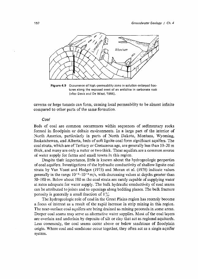
In areas of folded carbonate rocks, the zones of fracture concentration and solution enlargement are commonly associated with the crest of anticlines and to a lesser extent with synclinal troughs (Figure 4.9). In situations where rapid direct recharge can occur, fracture enlargement by dissolution has great influence. In the situation illustrated in Figure 4.9, water that infiltrates into the fractured carbonate rock beneath the alluvium will cause solution enlargement if the alluvium is devoid of carbonate minerals. If the alluvium has a significant carbonate-mineral content, groundwater would normally become saturated with respect to calcite and dolomite prior to entry into the fracture zones in the carbonate rock. In fractured carbonate rock in which solution channeling has been active in the geologic past,
157 Groundwater Geology / Ch. 4
Figure 4.9 Occurrence of high-permeability zone in solution-enlarged fractures along the exposed crest of an anticline in carbonate rock (after Davis and De Wiest, 1966).
caverns or large tunnels can form, causing local permeability to be almost infinite compared to other parts of the same formation.
Coal
Beds of coal are common occurrences within sequences of sedimentary rocks formed in floodplain or deltaic environments. In a large part of the interior of North America, particularly in parts of North Dakota, Montana, Wyoming, Saskatchewan, and Alberta, beds of soft lignite coal form significant aquifers. The coal strata, which are of Tertiary or Cretaceous age, are generally less than I 0-20 m thick, and many are only a meter or two thick. These aquifers are a common source of water supply for farms and small towns in this region.
Despite their importance, little is known about the hydrogeologic properties of coal aquifers. Investigations of the hydraulic conductivity of shallow lignite coal strata by Van Yoast and Hedges (1975) and Moran et al. (1976) indicate values generally in the range 10-c10-4 m/s, with decreasing values at depths greater than 50-100 m. Below about 100 m the coal strata are rarely capable of supplying water at rates adequate for water supply. The bulk hydraulic conductivity of coal seams can be attributed to joints and to openings along bedding planes. The bulk fracture porosity is generally a small fraction of 1 %.
The hydrogeologic role of coal in the Great Plains region has recently become a focus of interest as a result of the rapid increase in strip mining in this region. The near-surface coal aquifers are being drained as mining proceeds in some areas. Deeper coal seams may serve as alternative water supplies. Most of the coal layers are overlain and underlain by deposits of silt or clay that act as regional aquitards. Less commonly, the coal seams occur above or below sandstone of floodplain origin. Where coal and sandstone occur together, they often act as a single aquifer system.
Shale
Shale beds constitute the thickest and most extensive aquitards in most sedimentary basins. Shale originates as mud laid down on ocean bottoms, in the gentle-water areas of deltas, or in the backswamp environments of broad floodplains. Diagenetic processes related to compaction and tectonic activity convert the clay to shale. Mud, from which shale is formed, can have porosities as high as 70-80 % prior to burial. After compaction, however, shale general1y has a primary porosity of less than 20 % and in some cases less than 5 %. In outcrop areas, shale is commonly brittle, fractured, and often quite permeable. At depth, however, shale is generally softer, fractures are much less frequent, and permeability is generally very low. Some shale beds are quite plastic and fractures are insignificant.
Values of the hydraulic conductivity of intact samples of shale tested in the laboratory (Peterson, 1954; Young et al., 1964; Davis, 1969; Moran et al., 1976) are rarely larger than 10-9 m/s and are commonly in the range 10- 12-10- 10 m/s. It is evident from the Darcy relation that even under strong hydraulic gradients, groundwater in unfractured shale cannot move at rates greater than a few centimeters per century. These rates are hardly significant on a human time scale, but on a geological time scale the flow of groundwater through intact shale can be a significant component in the water budget of regional aquifers confined by shale. Within a few hundreds of meters of ground surface, fractures in shale can impart a significant component of secondary porosity and permeability. Even in situations where hairline fractures exist in relatively wide spacing, the very small secondary porosity they create (perhaps as low as 10-4-10-s) can produce secondary permeability of magnitudes that exceed the primary permeability.
4.6 Igneous and Metamorphic Rocks
Solid samples of unfractured metamorphic rock and plutonic igneous rock have porosities that are rarely larger than 2 %. The intercrystalline voids that make up the porosity are minute and many are not interconnected. Because of the small pore sizes and low degree of pore interconnectivity, the primary permeabilities of these rocks are extremely small. Measurements on intact specimens of metamorphic rocks (metasediments) from the Marquette Mining district in Michigan indicate primary permeability values in the range of 0.00019 millidarcy (10- 11-10- 13 m/s) expressed as hydraulic conductivity at room temperature for quartzite, mica schist, chert, slate, and graywacke (Stuart et al., 1954). Measurements of the permeability of granite in boreholes in which fractures are absent generally yield values on the order of 10-3 millidarcy (10- 11 m/s). Permeabilities of this magnitude indicate that these rocks are impermeable within the context of most groundwater problems.
In terrain composed of plutonic igneous rocks and crystalline metamorphic rocks, appreciable fracture permeability generally occurs within tens of meters and in some cases within a few hundred meters of ground surface. The fractures are
158
159 Groundwater Geology / Ch. 4
caused by changes in the stress conditions that have occurred during various episodes in the geologic history of the rocks. The widths of fracture openings are generally less than 1 mm. Since the discharge of groundwater is proportional to the fracture width raised to a power of about 3 [Eq. (2.86)], the difference in permeability between rock masses with fracture widths of tenths of a millimeter and those with fracture widths on the order of millimeters or more is enormous.
Tolman (1937) and Davis (1969) draw attention to the fact that in some cases dissolution of siliceous rocks may cause significant increases in the widths of fracture openings. Davis presented a hypothetical example whereby recharge water passing through the upper 10 m of a quartzite removes sufficient silica to widen fractures by 0.38 mm in 105 years. This widening could be very significant in terms of fluid flow. Davis indicates that several factors reduce or negate the tendency toward rapid opening by solution of cracks in crystalline rocks. As groundwater passes through overburden prior to entering the fractured rock, it normally acquires appreciable dissolved silica. It is therefore relatively unaggressive with respect to silicate minerals along the fracture faces. Unlike most carbonate rocks, silica-rich rocks have an insoluble residue in the form of iron and aluminum oxides that will tend to clog the small fractures after weathering is initiated.
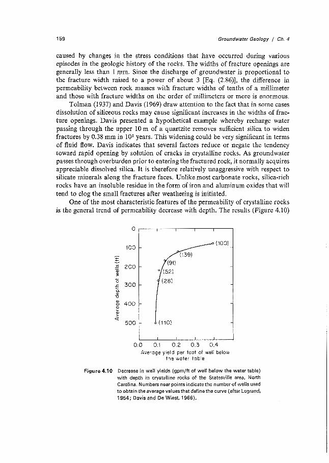
One of the most characteristic features of the permeability of crystalline rocks is the general trend of permeability decrease with depth. The results (Figure 4.10)
-t/)
(i3 ~
0 J::
a. Q)
-0 Q)
O' 0
Qi >
<t
0
100 (100)
200
300
400
500 (110)
0.0 0.1 0.2 0.3 0.4 Average yield per foot of well below
the water table
Figure 4.10 Decrease in well yields (gpm/ft of well below the water table) with depth in crystalline rocks of the Statesville area, North Carolina. Numbers near points indicate the number of wells used to obtain the average values that define the curve (after Legrand, 1954; Davis and De Wiest, 1966).
160 Groundwater Geology I Ch. 4
of a study of a crystalline rock area (granite, gabbro, Gneiss, and schist) in North Carolina by LeGrand (1954) are a quantitative expression of the trend that well drillers observe in a more qualitative manner in many crystalline rock regions. Quantitative relations between depth and well yield have also been established by Summers (1972) for a Precambrian-rock area in Wisconsin. Fractured crystalline rocks are less permeable at greater depth because stress variations that cause fractures are larger and, over geologic time, occur more frequently near the ground surface. Fractures tend to close at depth because of vertical and lateral stresses imposed by overburden loads and "locked-in" horizontal stresses of tectonic origin. Rocks maintain much of their brittle character to depths of several kilometers. Fracture permeability can therefore exist to great depth. Striking evidence of this comes from tunnels and from mines at depths of 1 km and more where water flows actively into shafts and adits. In crystalline rock, dry mines are the exception rather than the rule.
In granite, the occurrence of near-horizontal fractures parallel to the ground surface has been attributed by LeGrand (1949) to the removal of overburden load caused by erosion. In an area in Georgia studied by LeGrand, these sheet fractures are an important source of water supply from shallow depths. With depth, fractures of this type decrease rapidly in frequency and aperture width. They are probably unimportant contributors to permeability at depths greater than about 100 m (Davis and De Wiest, 1966).
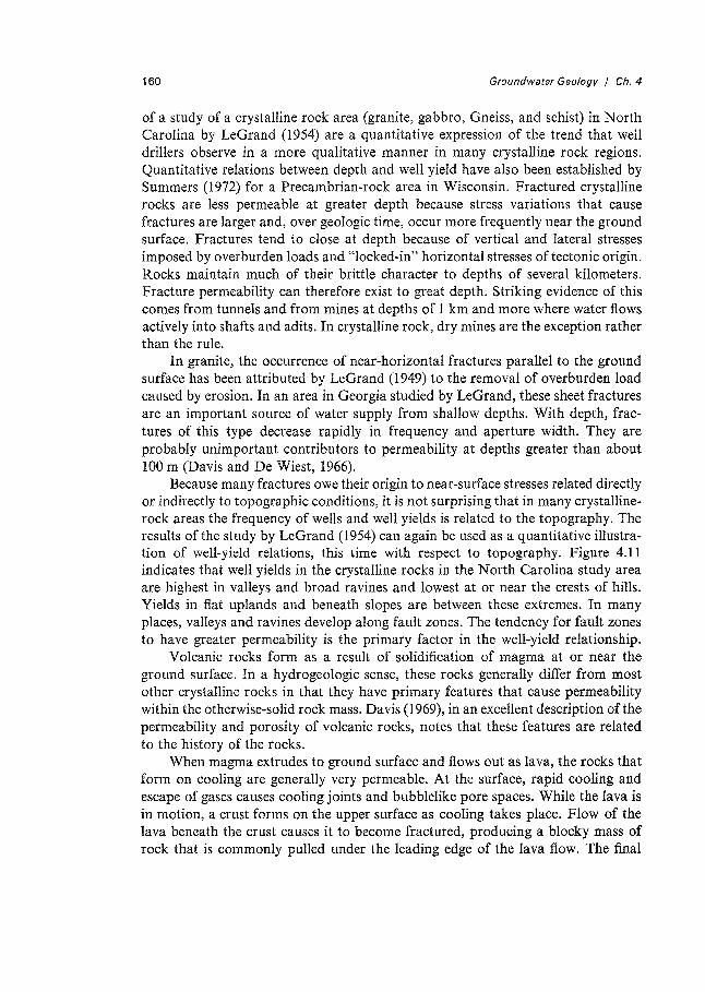
Because many fractures owe their origin to near-surface stresses related directly or indirectly to topographic conditions, it is not surprising that in many crystallinerock areas the frequency of wells and well yields is related to the topography. The results of the study by LeGrand (1954) can again be used as a quantitative illustration of well-yield relations, this time with respect to topography. Figure 4.11 indicates that well yields in the crystalline rocks in the North Carolina study area are highest in valleys and broad ravines and lowest at or near the crests of hills. Yields in flat uplands and beneath slopes are between these extremes. In many places, valleys and ravines develop along fault zones. The tendency for fault zones to have greater permeability is the primary factor in the well-yield relationship.
Volcanic rocks form as a result of solidification of magma at or near the ground surface. In a hydrogeologic sense, these rocks generally differ from most other crystalline rocks in that they have primary features that cause permeability within the otherwise-solid rock mass. Davis (1969), in an excellent description of the permeability and porosity of volcanic rocks, notes that these features are related to the history of the rocks.
When magma extrudes to ground surface and flows out as lava, the rocks that form on cooling are generally very permeable. At the surface, rapid cooling and escape of gases causes cooling joints and bubblelike pore spaces. While the lava is in motion, a crust forms on the upper surface as cooling takes place. Flow of the lava beneath the crust causes it to become fractured, producing a blocky mass of rock that is commonly pulled under the leading edge of the lava flow. The final
161
c 3: 0 ..c (/)
..... 0
£ (/)
" Q) Q) (,) )( Q)
0 (/)
0 ::J CY Q)
" Ci) ·:;:. Q) (/)
0 ..c 3:
.!:!!. Ci) 3:
0 Q) Cl 0 c Q) (,)
Q.; 0...
Groundwater Geology I Ch. 4
90
80
70
60
50
40
30
20
10
0 .____.~_._~_._~_.._~_,_~_._~..._~..._--.J.__-..J 0 10 20 30 40 50 60 70 80 90 100
Yield in gallons per minute
Figure 4.11 Cumulative frequency distribution of well yields with respect to topographic position, Statesville area, North Carolina (after Legrand, 1954; Davis and De Wiest, 1966).
result is a solid mass which in many places has coarse rubble zones above and below more dense rock (Davis, 1969). Gravels deposited by streams on lava landscapes are later covered by new flows. The blocky rock masses and associated gravel interbeds produce a bulk permeability that is very high in most young basalts. Other causes of high permeability in young basalts are gas vents, lava tubes, and tree molds. Alteration by deep burial or by the influx of cementing fluids during geologic time causes the permeability to decrease.
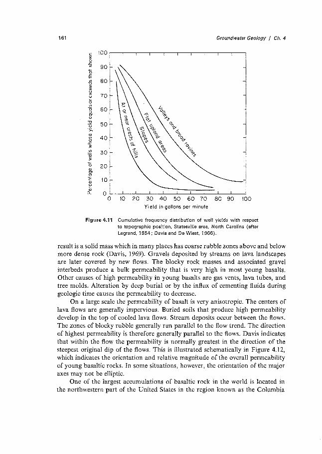
On a large scale the permeability of basalt is very anisotropic. The centers of lava flows are generally impervious. Buried soils that produce high permeability develop in the top of cooled lava flows. Stream deposits occur between the flows. The zones of blocky rubble generally run parallel to the flow trend. The direction of highest permeability is therefore generally parallel to the flows. Davis indicates that within the flow the permeability is normally greatest in the direction of the steepest original dip of the flows. This is illustrated schematically in Figure 4.12, which indicates the orientation and relative magnitude of the overall permeability of young basaltic rocks. In some situations, however, the orientation of the major axes may not be elliptic.
One of the largest accumulations of basaltic rock in the world is located in the northwestern part of the United States in the region known as the Columbia
162
I I I I I
I
Groundwater Geology / Ch. 4
Figure 4.12 Probable orientation and relative magnitude of the bulk permeability of young basaltic rocks (after Davis, 1969).
River Plateau. During Miocene and Pliocene time, enormous volumes of magma welled up through fissures and spread out in broad sheets over areas estimated to be as large as several million square kilometers. Consequently, much of the magma had a low gas content. The basalt in this region is generally quite dense, with only limited zones of vesicular basalt. Extensive river-deposited sediments occur between many of the basalt flows. The average total thickness of the basalt sequence over the Columbia River Plateau is about 550 m.
Studies in boreholes in the lower part of the basalt sequence at a site in the southeastern part of the State of Washington yielded hydraulic conductivity, transmissivity, and porosity data (Atlantic-Richfield Hanford Company, 1976), summarized in Table 4.1. The river-deposited interbeds and the zones of basalts
Table 4.1 Range of Hydrologic Properties of lower Yakima Basalt Flows and lnterbeds
Hydraulic conductivity Porosity
(m/s} (%)
Dense basalt 10-1 LlQ-.8 0.1-1 Vesicular basalt 10-9-10-s 5 Fractured, weathered,
or brecciated basalt 10-9-10-5 10 Inter beds 10-s_10-s 20
163 Groundwater Geology I Ch. 4
that are vesicular, fractured, weathered, or brecciated are aquifers in which predominantly horizontal regional fl.ow occurs. The zones of dense basalt have lower hydraulic conductivity and effective porosity but are, nevertheless, generally capable of transmitting considerable water. Some zones of dense, unfractured basalt have very low hydraulic conductivity and probably act as regional aquitards.
4. 7 Permafrost
Within the Arctic circle, perennially frozen ground known as permafrost is present almost everywhere. In the most northerly regions of Canada, Alaska, Greenland, Scandinavia, and the USSR, permafrost is continuous, but in much of the inhabited or resource frontier northland, the permafrost zones are discontinuous. Except in the high Andes and in Antarctica, permafrost is absent in the southern hemisphere.
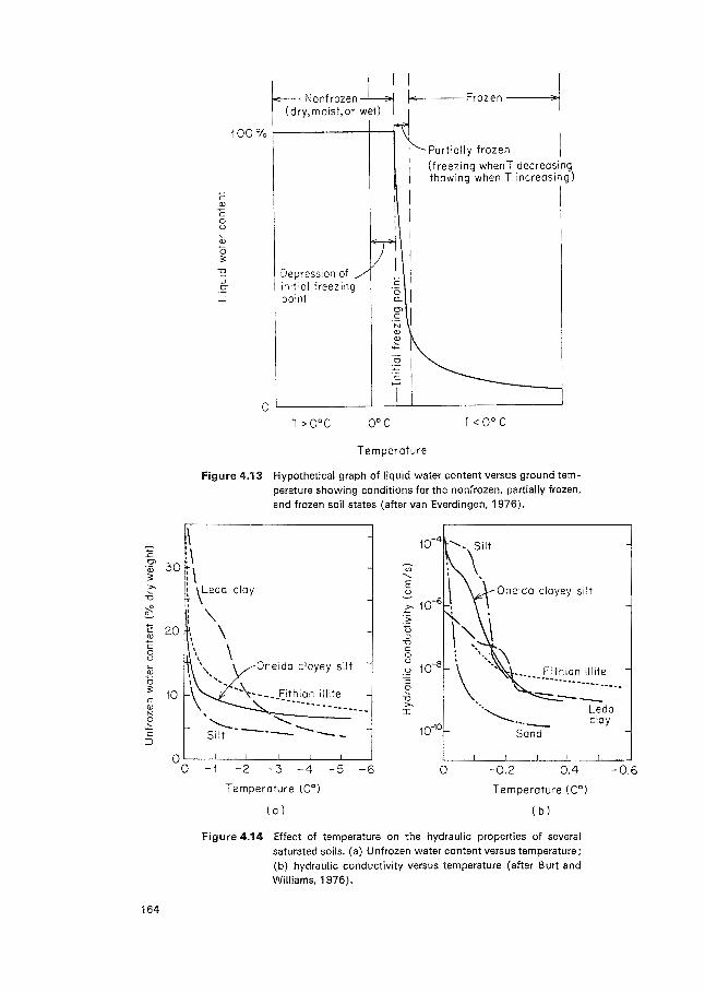
Contrary to what one might intuitively expect, permafrost does not necessarily form at all locations where the ground temperature declines to 0°C. Temperatures significantly below 0°C are often required to initiate the change of pore water into ice (Anderson and Morgenstern, 1973; Banin and Anderson, 1974). The occurrence and magnitude of the depression in the initial freezing point depend on a number of factors, including the fluid pressure, the salt content of the pore water, the grainsize distribution of the soil, the soil mineralogy, and the soil structure (van Everdingen, 1976). The relations between liquid water content in the pore water and temperatures of the bulk medium are illustrated in Figure 4.13. When the soil is partially frozen, the material contains both liquid water and ice. The term "permafrost" should be reserved for material in which water persists in the frozen or partially frozen state throughout the year. The 0°C temperature condition indicates little about the exact physical state of the pore water.
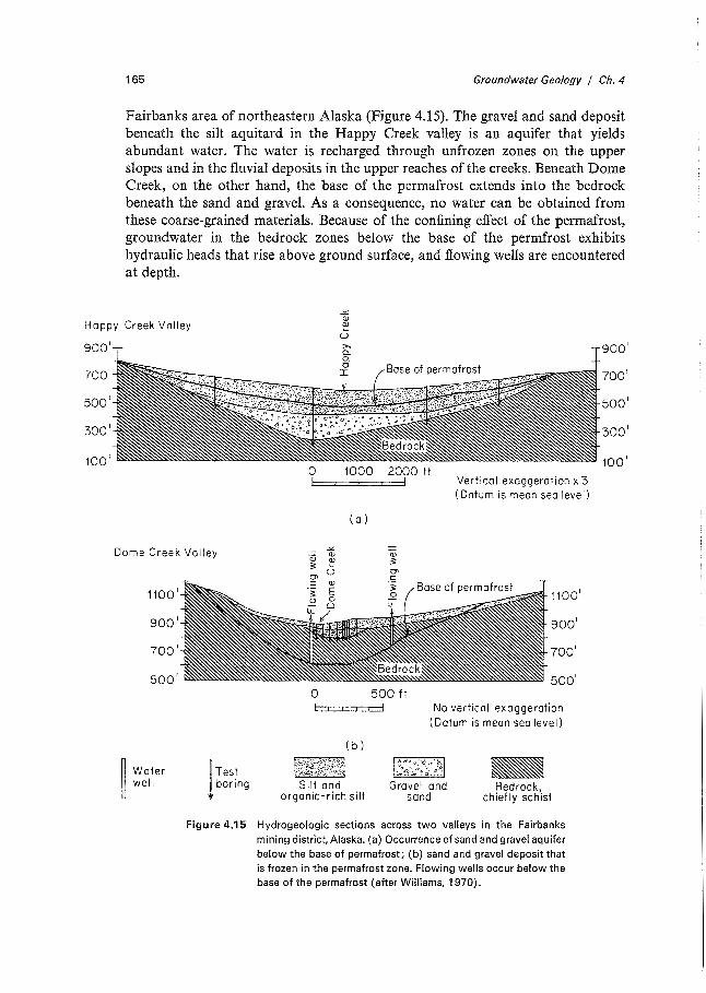
The hydrogeologic importance of permafrost lies in the large differences in hydraulic conductivity that exist for most geologic materials between their frozen and unfrozen states. Figure 4.14(a) shows the relation between the content of unfrozen pore water and temperature for several soils, and Figure 4. l 4(b) shows the effect of this relationship on the hydraulic conductivity. The content of unfrozen water decreases and the pore ice content increases when the bulk temperature of the material is lowered from 0°C toward -1°C. The hydraulic conductivities decline by several orders of magnitude as the temperature declines a few tenths of a degree below 0°C. Fine sand, for example, which could be an aquifer in an unfrozen state under the appropriate stratigraphic conditions, becomes a low-permeability aquitard at a temperature slightly below 0°C. Silt that could have leaky aquitard characteristics in an unfrozen state becomes an impervious aquitard when fully frozen.
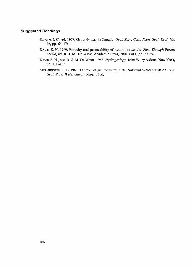
The importance of the permafrost configuration on the distribution of aquifers can be shown with reference to cross sections across two alluvial valleys in the
c Cl)
c 0 u
Cl)
0 3
-0 Depression of ::l
initial freezing 0-
_J point
T>0°C
I I
I I I I I I
c I -;:; I a. Cl'
I s N Cl)
~
0°C
Temperature
Frozen--1
Portially frozen I (freezing whenT decreasing thawing when T increasing)
T< 0° C
Figure 4.13 Hypothetical graph of liquid water content versus ground temperature showing conditions for the nonfrozen, partially frozen, and frozen soil states (after van Everdingen, 1976).
:g, 30 \ \ -~ : \
~ \Ledo
~ 20 c 0 u
\ '\. I I
' \ \ \
\
' ',,
cloy Oneida clayey silt
\ \
Oneida clayey silt •• £"ithion illite
...... --\-- __ Fithian illite
··-·------ ........ _
164
10 -------·--------.... ......._ -..........: Silt ----......_ __ 10-10
0'--~-'-~-'-~~'--~-'-~-'-~--J
0 -1 -2 -3 -4 -5 -6 0 -0.2 -0.4
Temperature (C 0) Temperature ( C0
)
(a) ( b)
Figure 4.14 Effect of temperature on the hydraulic properties of several saturated soils. (a) Unfrozen water content versus temperature; (b) hydraulic conductivity versus temperature (after Burt and Williams, 1976).
-0.6
165 Groundwater Geology I Ch. 4
Fairbanks area of northeastern Alaska (Figure 4.15). The gravel and sand deposit beneath the silt aquitard in the Happy Creek valley is an aquifer that yields abundant water. The water is recharged through unfrozen zones on the upper slopes and in the flu vial deposits in the upper reaches of the creeks. Beneath Dome Creek, on the other hand, the base of the permafrost extends into the bedrock beneath the sand and gravel. As a consequence, no water can be obtained from these coarse-grained materials. Because of the confining effect of the permafrost, groundwater in the bedrock zones below the base of the permfrost exhibits hydraulic heads that rise above ground surface, and flowing wells are encountered at depth.
Happy Creek Valley
900 1
7001
5001
3001
1001
0 1000 2000 ft
(a)
Vertical exaggeration x 3 (Datum is mean sea level)
Dome Creek Valley ..:.::. (ii
(ii (lJ
~ 3
11001
9001
7001
5001
~ Water II well lTest
boring
3 u
0
( b)
m~t.*1;{~f l~~;j Silt and
organic-rich silt
11001
9001
7001
5001
500 ft No vertical exaggeration
(Datum is mean sea level)
1:~~:~",;>~}~ ~ -'~ a ... ;
Gravel and sand
~ Bedrock,
chiefly schist
Figure 4.15 Hydrogeologic sections across two valleys in the Fairbanks mining district, Alaska. (a) Occurrence of sand and gravel aquifer below the base of permafrost; (b) sand and gravel deposit that is frozen in the permafrost zone. Flowing wells occur below the base of the permafrost (after Williams, 1970).
9001
7001
5001
3001
100'
Suggested Readings
BROWN, I. C., ed. 1967. Groundwater in Canada. Geo!. Surv. Can., Econ. Geo!. Rept. No. 24, pp. 65-171.
DAVIS, S. N. 1969. Porosity and permeability of natural materials. Flow Through Porous Media, ed. R. J.M. De Wiest. Academic Press, New York, pp. 53-89.
DAVIS, S. N., and R. J. M. DE WIEST. 1966. Hydrogeology. John Wiley & Sons, New York, pp. 318-417.
McGUINNESS, C. L. 1963. The role of groundwater in the National Water Situation. U.S. Geo!. Surv. Water-Supply Paper 1800.
166