Embed Size (px)
Citation preview
FENIE X . 2016 INSTRUCTION MANUALWEB. w w w.feniex.com
Feniex Product Copyrights This price List and the mentioned Feniex products include or describe copyrighted Feniex material. Laws in the United States and other countries preserve for Feniex Industries and its licensors certain exclusive rights for copyrighted material, including the exclusive right to copy, reproduce in any form, distribute and make derivative works of the copyrighted material. Accordingly, any copyrighted material of Feniex and its licensors contained herein or in the Feniex products described in this Price List may not be copied, reproduced, distributed, merged or modified,transmitted, transcribed, stored in retrieval system or translated into any language or computer language, in any form or by any means, without prior written permission of Feniex Industries, Inc.. Feniex and the stylized Feniex logo are registered in the U.S. Patent & Trademark Office.
This instruction manual serves as aguide for the 4200-DL Controller.
IMPORTANT! Please read through all provided instructions and any listed warnings in regards to product use.
4200-DL ControllerInstruction Manual
V.1.0
4200-DLModel # C-4200-DL
TM
FENIE X . 2016 INSTRUCTION MANUALWEB. w w w.feniex.com2
Table of Contents
Safety Regulations & Warranty 3Service after Expiration 3
Copyright 3Feniex Product Copyright 3
Box Contents 4System Specification 5Control Head Mounting 6
Vertical Mount 6Surface Mount 6
Relay Wiring Diagram 7
Configuration Record 9Configuration Record Diagram 10
Control Head Programming 11Help 11
Bluetooth 19Bluetooth Hardware 19Bluetooth Software 204200 App Requirements 20
FAQ 21
V1.0
Operational times are from 10 a.m. to 5 p.m. central time, Monday through Friday. Please do not send in product without contacting support first for a RMA number.
Service After ExpirationFeniex Industries will still provide service for all products after expiration of the warranty. For any issues, call the customer support line. In some instances it may be necessary for the product to be shipped, freight prepaid and insured for loss or damage to Feniex headquarters.
CopyrightThis instruction manual and the Feniex products described in this instruction manual may include or describe copyrighted Feniex material. Laws in the United States and other countries preserve for Feniex Industries and its licensors certain exclusive rights for copyrighted material, including the exclusive right to copy, reproduce in any form, distribute and make derivative works of the copyrighted material. Accordingly, any copyrighted material of Feniex and its licensors contained herein or in the Feniex products described in this instruction manual may not be copied, reproduced, distributed, merged or modified in any manner without the express written permission of Feniex Industries, Inc.
Feniex Product CopyrightsThe products described in this document are the property of Feniex Industries, Inc. It is furnished by express license agreement only and may be used only in accordance with the terms of such an agreement. Products and documentation are copyrighted materials. Making unauthorized copies is prohibited by law. No part of the product or documentation may be reproduced, transmitted, transcribed, stored in retrieval system or translated into any language or computer language, in any form or by any means, without prior permission from Feniex Industries, Inc.
Safety RegulationsThe following provides all the information necessary to safely operate the previously listed products of Feniex Industries, Inc. Please read this manual thoroughly before installing or operating your new product in order to prevent any damage or injury. Failure to follow the listed instructions in this manual may result in damage to your products or personal injury.• Proper installation of this product
requires good knowledge of automotive systems, electronics and procedures.
• Please guarantee all vital components of the vehicle are not in danger of being damaged by drilling holes necessary for installation. Check all sides of the mounting surface before drilling any holes into the vehicle.
• Do not install this product in any way that interferes with the deployment of the air bag. Doing so may damage the effectiveness of the air bag and can lead to serious personal and vehicle injury. The installer will assume full responsibility of proper installation of the new unit.
• Please clean the mounting surface before installation of the unit when using tape, brackets, magnet, Velcro or suction cups.
• The product's ground wire must be connected directly to the Negative (-) battery post for effective use of the unit. Please follow all wiring guidelines provided to guarantee long lifespan and productivity. Failing to follow these instructions may result in damage to the product.
WarrantyFeniex Industries, Inc. warrants to the original purchaser that the product shall be free from defects in material and workmanship for 5 years from the date of purchase for all LED products. Feniex Industries warranties speakers, sirens, flashers, and controllers for 2 years.If a warranty problem occurs, please contact customer support at 1.800.615.8350 or visit the web site at www.Feniex.com. If the product needs to be returned for repair or replacement, call our customer support line to receive a return merchandise authorization number.
Warning! Utilizing non-factory screws and mounting brackets may result in loss of warranty coverage.
TM
FENIE X . 2016 INSTRUCTION MANUALWEB. w w w.feniex.com 3
Safety Regulations & WarrantyV1.0
TM
FENIE X . 2016 INSTRUCTION MANUALWEB. w w w.feniex.com4
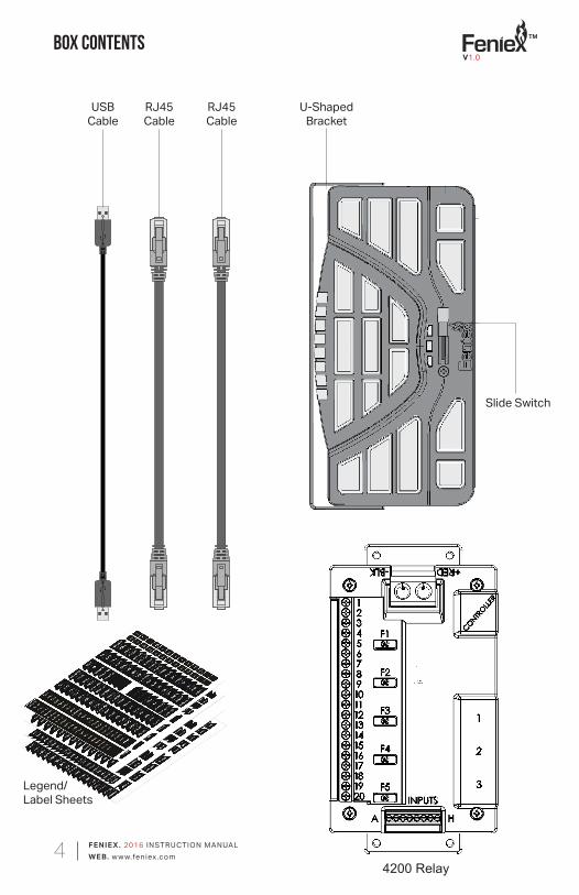
Slide Switch
U-ShapedBracket
USBCable
RJ45Cable
Legend/Label Sheets
Box contents
RJ45Cable
4200 Relay
V1.0
TM
FENIE X . 2016 INSTRUCTION MANUALWEB. w w w.feniex.com5
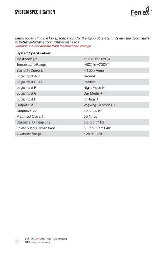
System Specification
Below you will find the key specifications for the 4200-DL system. Review the information to better determine your installation needs.Warning! Do not deviate from the specified voltage.
System Specification:Input Voltage: 11VDC to 16VDCTemperature Range: -40C° to +70CV°Stand By Current: > 100m AmpsLogic Input A-B GroundLogic Input C-D-E PositiveLogic Input F Night Mode (+)Logic Input G Day Mode (+)Logic Input H Ignition (+)Output 1-2 WigWag 10 Amps (+)Outputs 3-20 10 Amps (+)Max Input Current 60 AmpsController Dimensions 6.8″ x 3.5″ 1.3″Power Supply Dimensions 6.33" x 3.3" x 1.48"Bluetooth Range 40ft (+/- 5ft)
V1.0
TM
FENIE X . 2016 INSTRUCTION MANUALWEB. w w w.feniex.com6
Control Head
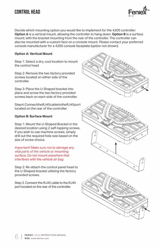
Decide which mounting option you would like to implement for the 4200 controller: Option A is a vertical mount, allowing the controller to hang down. Option B is a surface mount; with the bracket mounting from the rear of the controller. The controller can also be mounted with a custom face on a console mount. Please contact your preferred console manufacturer for a 4200 console faceplate (option not shown).
Option A: Vertical Mount
Step 1: Select a dry, cool location to mount the control head
Step 2: Remove the two factory provided screws located on either side of the controller.
Step 3: Place the U-Shaped bracket into place and screw the two factory provided screws back on each side of the controller.
Step 4. Connect the RJ45 cable to the RJ45 port located on the rear of the controller.
Option B: Surface Mount
Step 1: Mount the U-Shaped Bracket in the desired location using 2 self-tapping screws. If you wish to use machine screws, simply drill out the required hole size based on the size of screw choice.
Important! Make sure not to damage any vital parts of the vehicle or mounting surface. Do not mount anywhere that interferes with the vehicle air bag.
Step 2: Re-attach the control panel head to the U-Shaped bracket utilizing the factory provided screws.
Step 3. Connect the RJ45 cable to the RJ45 port located on the rear of the controller.
V1.0
TM
FENIE X . 2016 INSTRUCTION MANUALWEB. w w w.feniex.com7
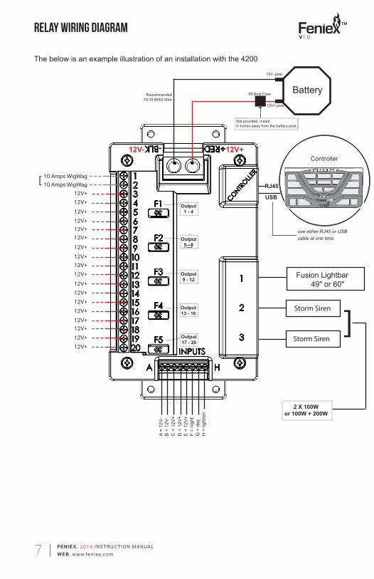
relay wiring Diagram
Fusion Lightbar49" or 60"
Storm Siren
Storm Siren
A =
12V-
B =
12V-
C =
12V
+D
= 1
2V+
E =
12V+
F =
nigh
tG
= d
ayH
= li
ghtio
n
Controller
RJ45
60 Amp Fuse
12V+ post
12V- post
Battery
10 Amps WigWag10 Amps WigWag
12V+12V+12V+12V+12V+12V+12V+12V+12V+12V+
12V+12V+12V+12V+12V+12V+12V+
12V+
12V- 12V+
The below is an example illustration of an installation with the 4200
Not provided, install 6 inches away from the battery post.
[
]
2 X 100W or 100W + 200W
Output 1 - 4
Output 5 - 8
Output 9 - 12
Output 13 - 16
Output 17 - 20
Recommended 10-12 AWG Wire
USB
use either RJ45 or USB cable at one time.
V1.0
TM
FENIE X . 2016 INSTRUCTION MANUALWEB. w w w.feniex.com8
Controller
RJ45
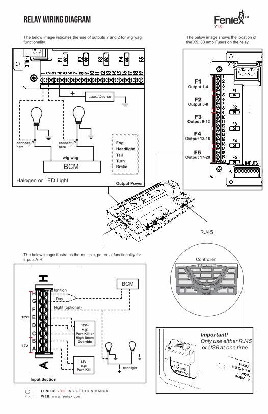
F1
F2
F3
F4
F5
relay wiring Diagram
Output PowerHalogen or LED Light
BCM
connecthere
connecthere
FogHeadlightTailTurnBrake
Load/Device
12V+
12V-
BCMIgnition
Day
Night (optional)
+Input Section
headlight
12V- e.g:
Park Kill
12V+ e.g:
Park Kill or High Beam Override
ABCDEFGH
Important! Only use either RJ45 or USB at one time.
The below image shows the location of the X5, 30 amp Fuses on the relay.
The below image indicates the use of outputs 7 and 2 for wig wag functionality.
The below image illustrates the multiple, potential functionality for inputs A-H.
Output 1-4
Output 5-8
Output 9-12
Output 13-16
Output 17-20
+
wig wag
V1.0
TM
FENIE X . 2016 INSTRUCTION MANUALWEB. w w w.feniex.com9
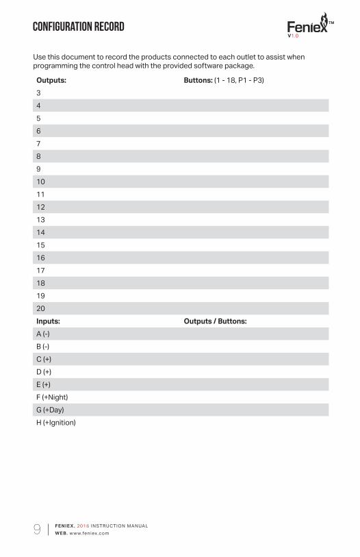
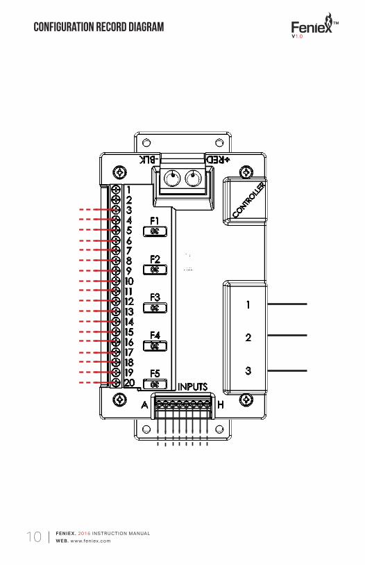
Use this document to record the products connected to each outlet to assist when programming the control head with the provided software package.
Outputs: Buttons: (1 - 18, P1 - P3)34567891011121314151617181920Inputs: Outputs / Buttons:A (-)B (-)C (+)D (+)E (+)
Configuration Record
F (+Night)G (+Day)H (+Ignition)
V1.0
TM
FENIE X . 2016 INSTRUCTION MANUALWEB. w w w.feniex.com10
Configuration Record diagram V1.0
TM
FENIE X . 2016 INSTRUCTION MANUALWEB. w w w.feniex.com11
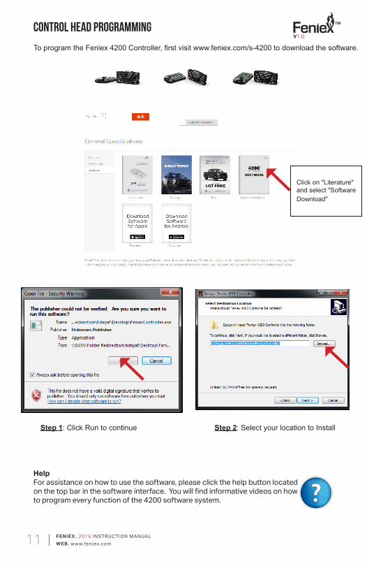
HelpFor assistance on how to use the software, please click the help button located on the top bar in the software interface. You will find informative videos on how to program every function of the 4200 software system.
Control Head Programming
Step 1: Click Run to continue Step 2: Select your location to Install
To program the Feniex 4200 Controller, first visit www.feniex.com/s-4200 to download the software.
Click on "Literature" and select "Software Download"
V1.0
TM
FENIE X . 2016 INSTRUCTION MANUALWEB. w w w.feniex.com12
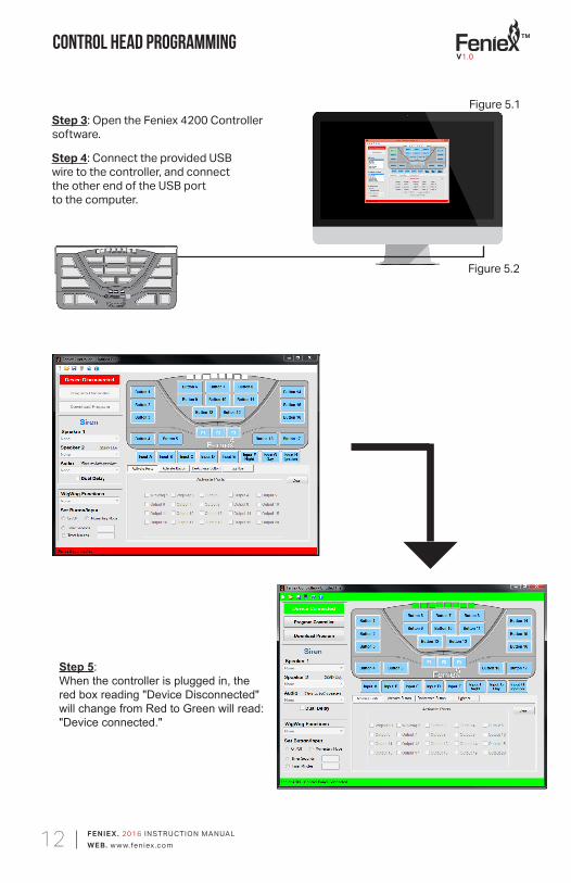
Step 3: Open the Feniex 4200 Controller software.
Step 4: Connect the provided USB wire to the controller, and connect the other end of the USB port to the computer.
Control Head Programming
Figure 5.2
Figure 5.1
Step 5: When the controller is plugged in, the red box reading "Device Disconnected" will change from Red to Green will read: "Device connected."
V1.0
TM
FENIE X . 2016 INSTRUCTION MANUALWEB. w w w.feniex.com13
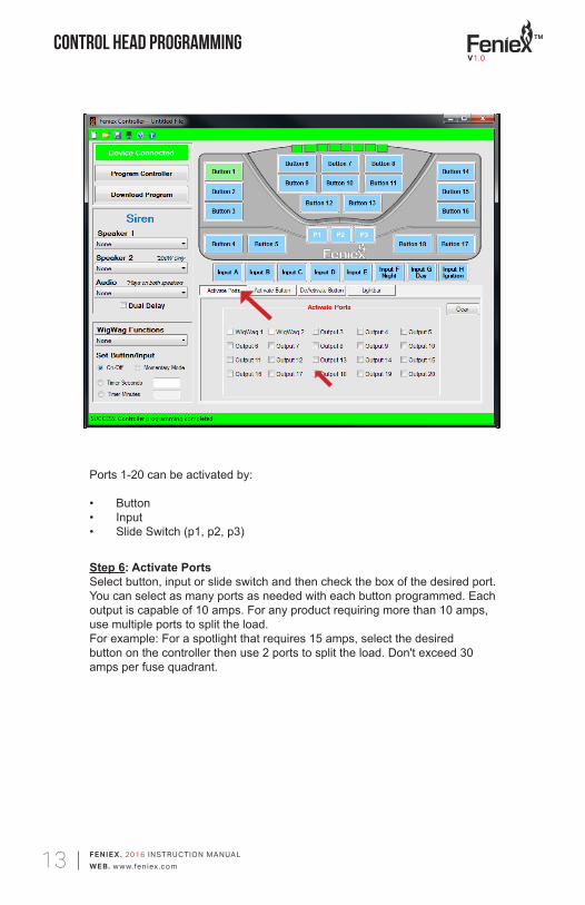
Step 6: Activate Ports Select button, input or slide switch and then check the box of the desired port. You can select as many ports as needed with each button programmed. Each output is capable of 10 amps. For any product requiring more than 10 amps, use multiple ports to split the load. For example: For a spotlight that requires 15 amps, select the desired button on the controller then use 2 ports to split the load. Don't exceed 30 amps per fuse quadrant.
Ports 1-20 can be activated by:
• Button • Input • Slide Switch (p1, p2, p3)
Control Head ProgrammingV1.0
TM
FENIE X . 2016 INSTRUCTION MANUALWEB. w w w.feniex.com14
Control Head Programming
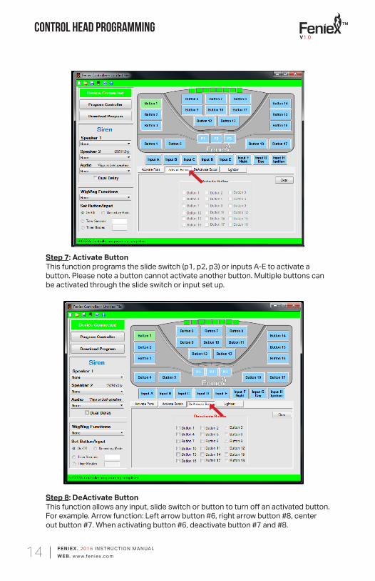
Step 7: Activate ButtonThis function programs the slide switch (p1, p2, p3) or inputs A-E to activate a button. Please note a button cannot activate another button. Multiple buttons can be activated through the slide switch or input set up.
Step 8: DeActivate ButtonThis function allows any input, slide switch or button to turn off an activated button. For example. Arrow function: Left arrow button #6, right arrow button #8, center out button #7. When activating button #6, deactivate button #7 and #8.
V1.0
TM
FENIE X . 2016 INSTRUCTION MANUALWEB. w w w.feniex.com15
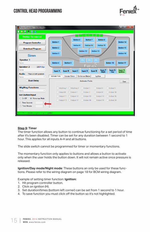
Step 9: Timer The timer function allows any button to continue functioning for a set period of time after it's been disabled. Timer can be set for any duration between 1 second to 1 hour. This applies for all inputs A-H and all buttons.
The slide switch cannot be programmed for timer or momentary functions.
The momentary function only applies to buttons and allows a button to activate only when the user holds the button down. It will not remain active once pressure is released.
Ignition/Day mode/Night mode: These buttons an only be used for these func-tions. Please refer to the wiring diagram on page 18 for BCM wiring diagram.
Example of setting timer function: Ignition: 1. Hit program controller button. 2. Click on ignition (H). 3. Set duration/times (bottom left corner) can be set from 1 second to 1 hour. 4. To save function you must click off the button so it's not highlighted.
Control Head ProgrammingV1.0
TM
FENIE X . 2016 INSTRUCTION MANUALWEB. w w w.feniex.com16
Control Head Programming
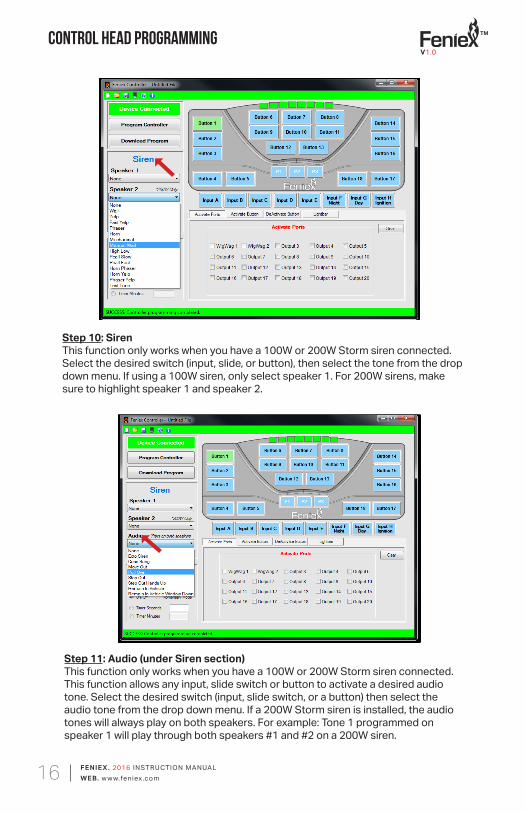
Step 10: SirenThis function only works when you have a 100W or 200W Storm siren connected. Select the desired switch (input, slide, or button), then select the tone from the drop down menu. If using a 100W siren, only select speaker 1. For 200W sirens, make sure to highlight speaker 1 and speaker 2.
Step 11: Audio (under Siren section)This function only works when you have a 100W or 200W Storm siren connected. This function allows any input, slide switch or button to activate a desired audio tone. Select the desired switch (input, slide switch, or a button) then select the audio tone from the drop down menu. If a 200W Storm siren is installed, the audio tones will always play on both speakers. For example: Tone 1 programmed on speaker 1 will play through both speakers #1 and #2 on a 200W siren.
V1.0
TM
FENIE X . 2016 INSTRUCTION MANUALWEB. w w w.feniex.com17
Control Head Programming
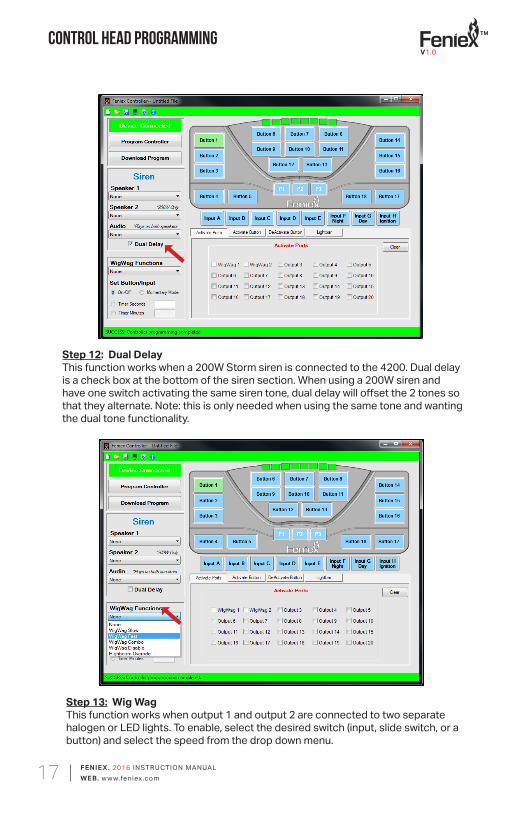
Step 12: Dual Delay This function works when a 200W Storm siren is connected to the 4200. Dual delay is a check box at the bottom of the siren section. When using a 200W siren and have one switch activating the same siren tone, dual delay will offset the 2 tones so that they alternate. Note: this is only needed when using the same tone and wanting the dual tone functionality.
Step 13: Wig Wag This function works when output 1 and output 2 are connected to two separate halogen or LED lights. To enable, select the desired switch (input, slide switch, or a button) and select the speed from the drop down menu.
V1.0
TM
FENIE X . 2016 INSTRUCTION MANUALWEB. w w w.feniex.com18
Control Head Programming
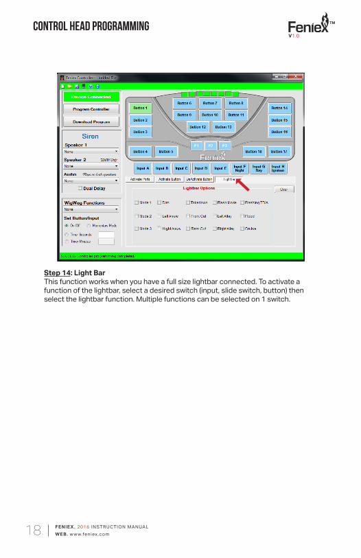
Step 14: Light BarThis function works when you have a full size lightbar connected. To activate a function of the lightbar, select a desired switch (input, slide switch, button) then select the lightbar function. Multiple functions can be selected on 1 switch.
V1.0
TM
FENIE X . 2016 INSTRUCTION MANUALWEB. w w w.feniex.com19
Bluetooth
Bluetooth Hardware
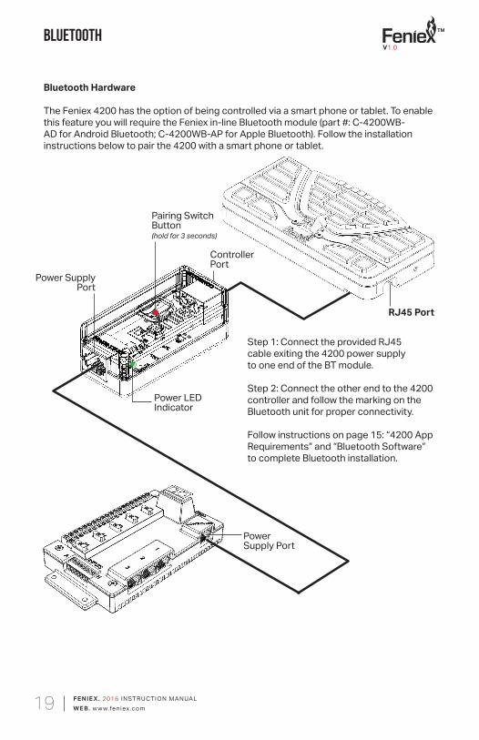
The Feniex 4200 has the option of being controlled via a smart phone or tablet. To enable this feature you will require the Feniex in-line Bluetooth module (part #: C-4200WB-AD for Android Bluetooth; C-4200WB-AP for Apple Bluetooth). Follow the installation instructions below to pair the 4200 with a smart phone or tablet.
Power LEDIndicator
Pairing Switch Button(hold for 3 seconds)
ControllerPort
Power Supply Port
PowerSupply Port
RJ45 Port
Step 1: Connect the provided RJ45 cable exiting the 4200 power supply to one end of the BT module.
Step 2: Connect the other end to the 4200 controller and follow the marking on the Bluetooth unit for proper connectivity.
Follow instructions on page 15: “4200 App Requirements” and “Bluetooth Software” to complete Bluetooth installation.
V1.0
TM
FENIE X . 2016 INSTRUCTION MANUALWEB. w w w.feniex.com20
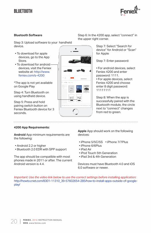
Bluetooth Software
Step 3: Upload software to your handheld device.
• To download for apple devices, go to the App Store.
• To download for android devices, visit the Feniex website at: http://www.feniex.com/s-4200
*The app is not yet available on Google Play
Step 4: Turn Bluetooth on using handheld device.
Step 5: Press and hold pairing switch button on Feniex Bluetooth device for 3 seconds.
4200 App Requirements:
Android App minimum requirements are the following:
• Android 2.2 or higher• Bluetooth 2.0 EDR with SPP support
The app should be compatible with most phones made in 2011 or after. The current Android version is 4.4.
Apple App should work on the following devices:
• iPhone 5/5C/5S • iPhone 7/7Plus• iPhone 6/6Plus • iPad Air• iPod Touch 5th Generation• iPad 3rd & 4th Generation
Devices must have Bluetooth 4.0 and iOS 6.0 software or newer.
Important: Use the video link below to use the correct settings before installing application:http://howto.cnet.com/8301-11310_39-57602654-285/how-to-install-apps-outside-of-google-play/
Bluetooth
Step 6: In the 4200 app, select “connect” in the upper right corner.
Step 7: Select “Search for device” for Android or “Scan” for Apple
Step 7: Enter password:
• For android devices, select Feniex 4200 and enter password: 1111.• For apple devices, select Feniex 4200 and choose enter 8 digit password: 11111111
Step 8: When the app is successfully paired with the Bluetooth module, the circle next to “connect” changes from red to green.
V1.0
TM
FENIE X . 2016 INSTRUCTION MANUALWEB. w w w.feniex.com21
FAQ
1. How do I know if there is power to my 4200 Relay?A flashing green LED light on the PCBA will indicate if there is power to the board if the firmware is fully operational.
2. Why can’t I program to outputs 1 - 2?Outputs 1 - 2 are only for the WigWag Function Box.
3. My controller does not turn on after I programmed it?Make sure to provide 12V+ into the "Ignition Input" (Input H).
4. What is the password for Feniex Bluetooth Module? Android: The password is: 1111Apple: The password is: 11111111
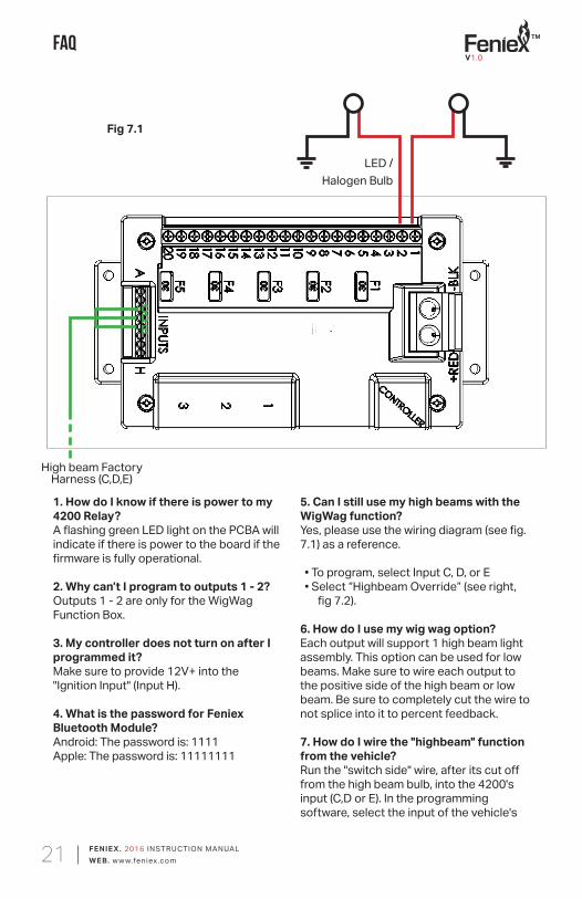
LED /Halogen Bulb
High beam FactoryHarness (C,D,E)
Fig 7.1
5. Can I still use my high beams with the WigWag function?Yes, please use the wiring diagram (see fig. 7.1) as a reference.
• To program, select Input C, D, or E• Select “Highbeam Override” (see right,
fig 7.2).
6. How do I use my wig wag option?Each output will support 1 high beam light assembly. This option can be used for low beams. Make sure to wire each output to the positive side of the high beam or low beam. Be sure to completely cut the wire to not splice into it to percent feedback.
7. How do I wire the "highbeam" function from the vehicle?Run the "switch side" wire, after its cut off from the high beam bulb, into the 4200's input (C,D or E). In the programming software, select the input of the vehicle's
CDE
V1.0
TM
FENIE X . 2016 INSTRUCTION MANUALWEB. w w w.feniex.com22
FAQ
Important! Do not reverse-connect the 4200 relay, by switching the red positive 12V(+) wire with the ground 12V(-) wire.
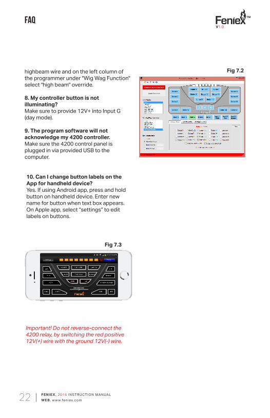
10. Can I change button labels on the App for handheld device?Yes. If using Android app, press and hold button on handheld device. Enter new name for button when text box appears. On Apple app, select “settings” to edit labels on buttons.
Fig 7.2
Fig 7.3
highbeam wire and on the left column of the programmer under "Wig Wag Function" select "high beam" override.
8. My controller button is not illuminating?Make sure to provide 12V+ into Input G (day mode).
9. The program software will not acknowledge my 4200 controller.Make sure the 4200 control panel is plugged in via provided USB to the computer.
V1.0