Embed Size (px)
Citation preview

5-CHANNEL COMPUTER RADIO

3XF421EX MANUAL • Table of Contents
I. INTRODUCTION
1. Using This Manual 42. Features 4
2.1 Transmitter Features 42.2 Receiver Features 42.3 Servo Features 52.4 Servo Layout 5
3. Specifications 63.1 System Specifications 63.2 Transmitter Specifications 63.3 Servo Specifications 63.4 Receiver Specifications 73.5 Charger Specifications 73.6 Airborne Battery Pack 7
4. Battery Charging 84.1 Transmitter/Receiver 84.2 Charger 8
5. Trainer System 9
II. XF421EX MANUAL
1. Transmitter Controls 101.1 Control Identification and Location 101.2 Receiver Channel Assignment/
Transmitter Throttle ALT 101.3 Transmitter Rear 111.4 Control Stick Length Adjustment 111.5 Direct Servo Control (DSC) 121.6 Neck Strap Attachment 12
2. Connections 132.1 Installation Requirements 132.2 Connections 13
3. Key Input and Display 144. Battery Alarm and Display 145. Input Mode and Functions 15
5.1 Normal Display 155.2 Mode Types 155.3 System Mode 165.4 Function Mode 16
6. Functions (System Mode) 176.1 Data Reset 176.2 Model Selection 186.3 Wing Type Selection 196.4 Model Name Entry 21
7. Functions (Function Mode) 227.1 Servo Reversing 227.2 Sub-Trim 237.3 Travel Adjustment 24
8. Data Sheet 25
III. IMPORTANT INFORMATION
1. General Notes 262. Daily Flight Checks 263. Warranty Coverage 274. Repair Service Instructions 275. Frequency Chart 28
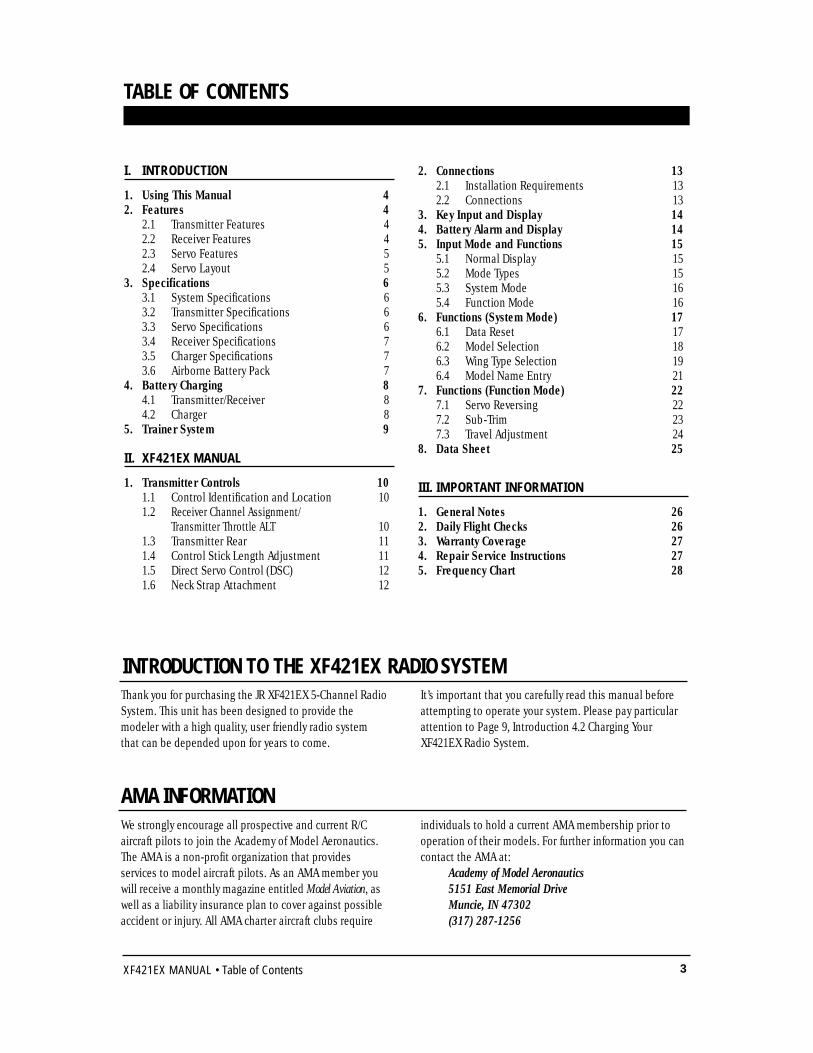
TABLE OF CONTENTS
We strongly encourage all prospective and current R/Caircraft pilots to join the Academy of Model Aeronautics.The AMA is a non-profit organization that providesservices to model aircraft pilots. As an AMA member youwill receive a monthly magazine entitled Model Aviation, aswell as a liability insurance plan to cover against possibleaccident or injury. All AMA charter aircraft clubs require
individuals to hold a current AMA membership prior tooperation of their models. For further information you cancontact the AMA at:
Academy of Model Aeronautics5151 East Memorial DriveMuncie, IN 47302(317) 287-1256
Thank you for purchasing the JR XF421EX 5-Channel RadioSystem. This unit has been designed to provide themodeler with a high quality, user friendly radio systemthat can be depended upon for years to come.
It’s important that you carefully read this manual beforeattempting to operate your system. Please pay particularattention to Page 9, Introduction 4.2 Charging YourXF421EX Radio System.
AMA INFORMATION
INTRODUCTION TO THE XF421EX RADIO SYSTEM
4 XF421EX MANUAL • INTRODUCTION 1: Using This Manual / INTRODUCTION 2: Features
The XF421EX is a full feature introductory computerradio that can be used for airplanes.A blank data sheet is included at the end of thismanual. Once you have input all the necessary datainto your transmitter for a particular model, we
strongly recommend that you write that informationdown on a copy of the data sheet provided. This is toinsure that, in the rare case of a memory failure, youwill not lose your data.
INTRODUCTION 1: Using This Manual
USING THIS MANUAL1
• Easy-to-read LCD screen• 2 model memory• Trainer system compatible with most other JR
radios• 2 conveniently mounted programming switches• Computer designed ergonomically styled case• Adjustable stick length
• Throttle trim only affects idle position• Two speed scrolling—Press and hold the
appropriate button to scroll quickly or press andrelease to scroll in steps
• Flaperons mixing• Delta wing mixing• V-tail mixing
R600 Receiver• The R600’s extremely compact size allows it to fit
easily in limited spaces.• An independent laboratory ranked the R600
receiver with JR’s patented ABC&W circuitry as one of the best receivers ever tested in terms of 3IM, 2IM, adjacent channel rejection, signal-to-noise ratio, and on-channel capture point.
• A special “unwanted interference limiter” ignores signals outside of the R600’s band width when the receiver is on and the transmitter is off. The
limiter also prevents servos from random glitching when other transmitters are operating in close proximity.
• The electrical circuitry in the R600 is state-of-the-art surface mount technology (SMT). These SMT components draw less current, thus increasing flying time. Flush mounting of these componentsalso reduces the risk of vibration wear and damage.
• The R600 is compatible with all JR FM-transmitting radios.
TRANSMITTER FEATURES2.1
RECEIVER FEATURES2.2
INTRODUCTION 2: Features
5XF421EX MANUAL • INTRODUCTION 2: Features
INTRODUCTION 2: Features continued
517 Servo• A .03ms deadband amplifier insures accurate
neutral centering.• Low current drain.
• Ball bearing supported ouput shaft• An indirect drive feedback potentiometer gives
additional protection from vibration.
SERVO FEATURES2.3
SERVO LAYOUT2.4
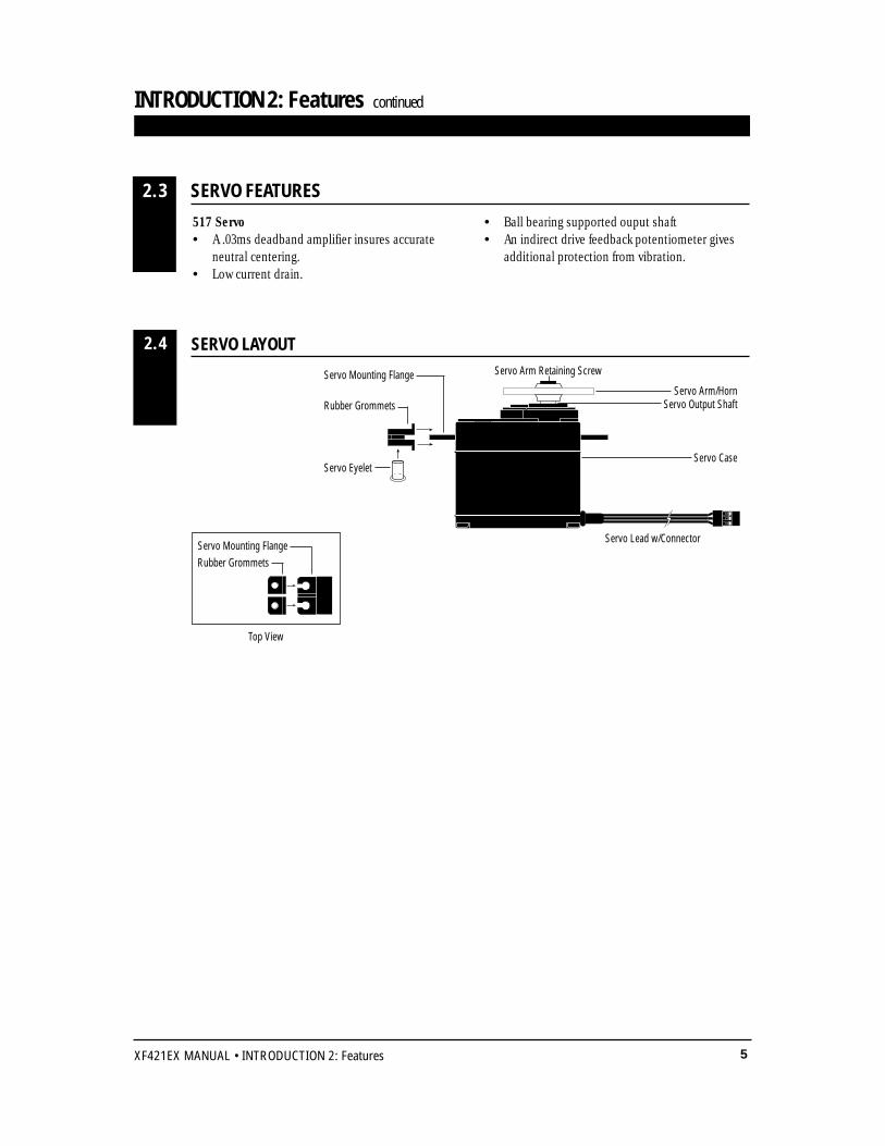
Servo Mounting Flange
Rubber Grommets
Rubber Grommets
Servo Case
Servo Lead w/Connector
Servo Output Shaft
Servo Mounting FlangeServo Arm/Horn
Servo Arm Retaining Screw
Servo Eyelet
Top View
6 XF421EX MANUAL • INTRODUCTION 3: Specifications
INTRODUCTION 3: Specifications
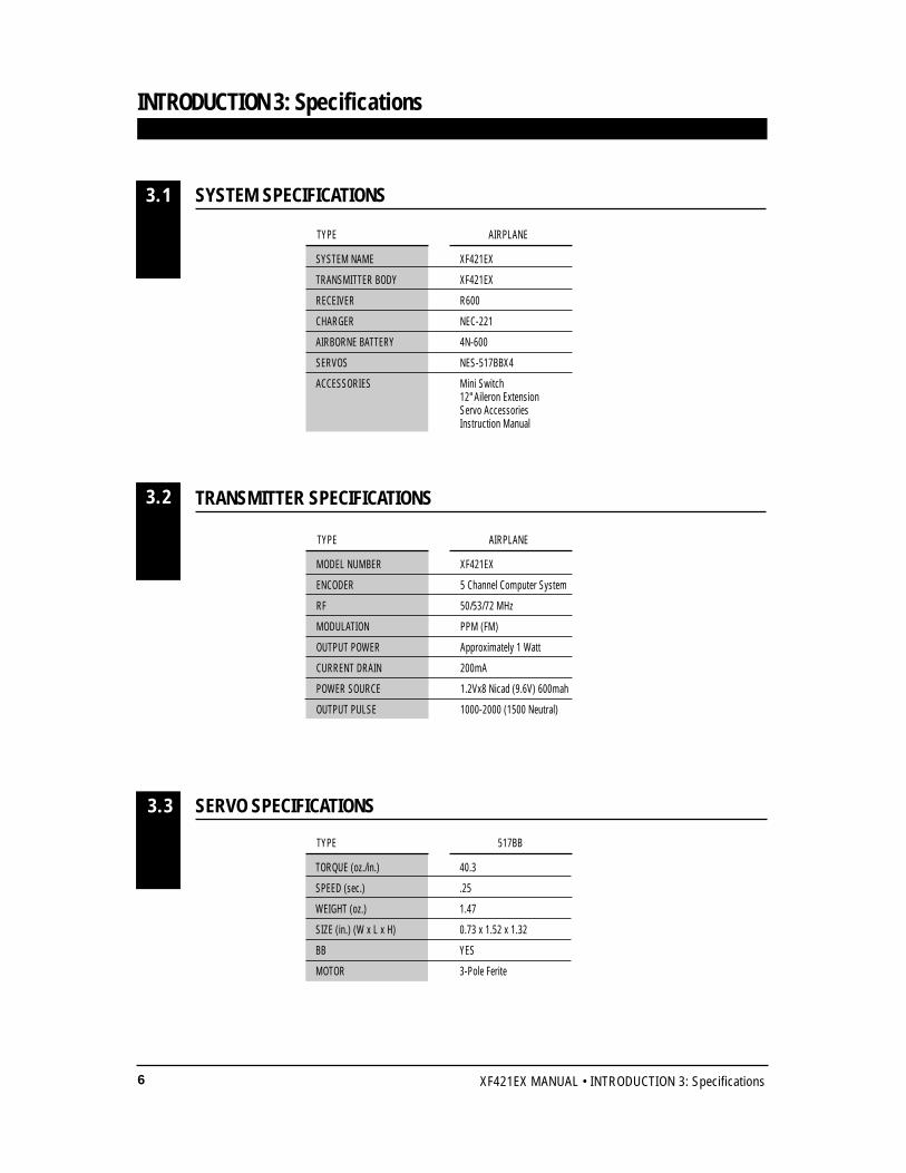
SYSTEM SPECIFICATIONS
TRANSMITTER SPECIFICATIONS
3.1
3.2
SYSTEM NAME XF421EX
TRANSMITTER BODY XF421EX
RECEIVER R600
CHARGER NEC-221
AIRBORNE BATTERY 4N-600
SERVOS NES-517BBX4
ACCESSORIES Mini Switch12" Aileron ExtensionServo AccessoriesInstruction Manual
TYPE AIRPLANE
MODEL NUMBER XF421EX
ENCODER 5 Channel Computer System
RF 50/53/72 MHz
MODULATION PPM (FM)
OUTPUT POWER Approximately 1 Watt
CURRENT DRAIN 200mA
POWER SOURCE 1.2Vx8 Nicad (9.6V) 600mah
OUTPUT PULSE 1000-2000 (1500 Neutral)
TYPE AIRPLANE
SERVO SPECIFICATIONS3.3
TORQUE (oz./in.) 40.3
SPEED (sec.) .25
WEIGHT (oz.) 1.47
SIZE (in.) (W x L x H) 0.73 x 1.52 x 1.32
BB YES
MOTOR 3-Pole Ferite
TYPE 517BB
7XF421EX MANUAL • INTRODUCTION 3: Specifications
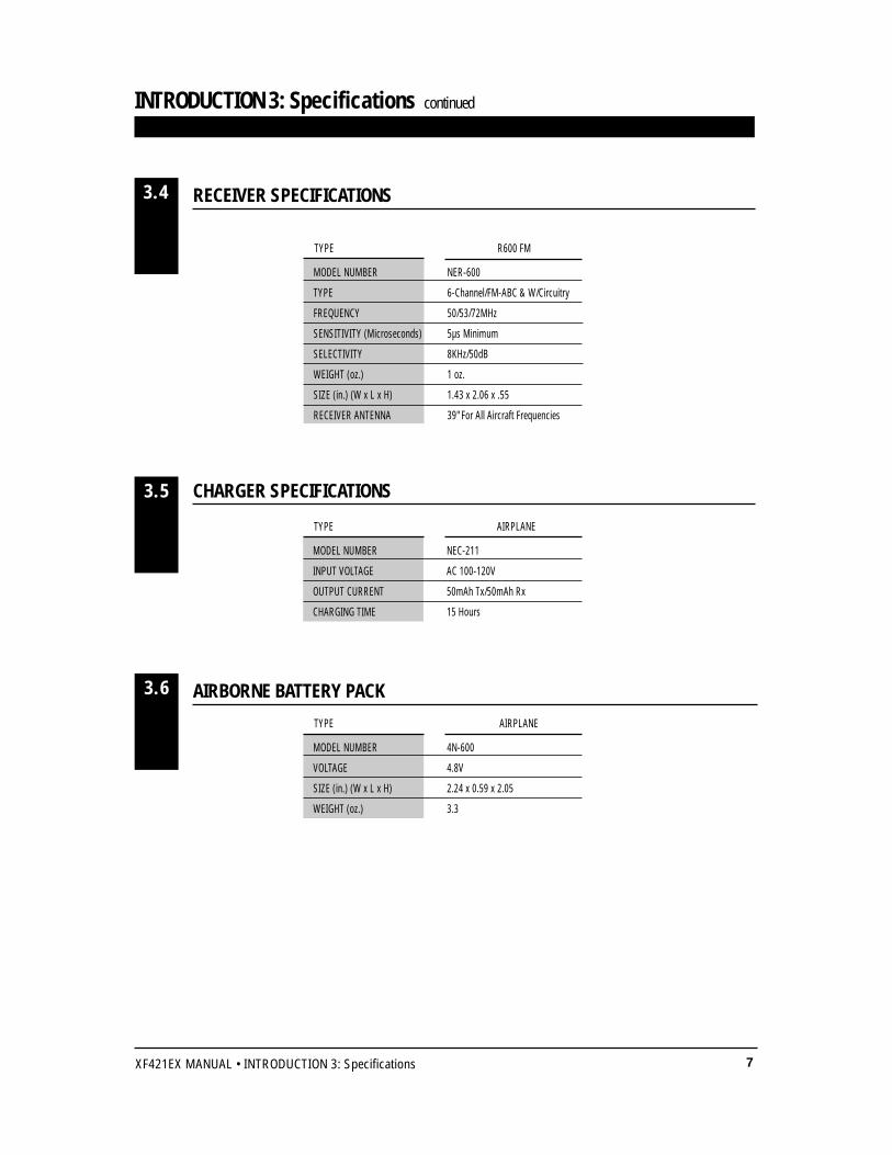
RECEIVER SPECIFICATIONS3.4
CHARGER SPECIFICATIONS
AIRBORNE BATTERY PACK
3.5
3.6
MODEL NUMBER NER-600
TYPE 6-Channel/FM-ABC & W/Circuitry
FREQUENCY 50/53/72MHz
SENSITIVITY (Microseconds) 5µs Minimum
SELECTIVITY 8KHz/50dB
WEIGHT (oz.) 1 oz.
SIZE (in.) (W x L x H) 1.43 x 2.06 x .55
RECEIVER ANTENNA 39" For All Aircraft Frequencies
TYPE R600 FM
MODEL NUMBER NEC-211
INPUT VOLTAGE AC 100-120V
OUTPUT CURRENT 50mAh Tx/50mAh Rx
CHARGING TIME 15 Hours
TYPE AIRPLANE
MODEL NUMBER 4N-600
VOLTAGE 4.8V
SIZE (in.) (W x L x H) 2.24 x 0.59 x 2.05
WEIGHT (oz.) 3.3
TYPE AIRPLANE
INTRODUCTION 3: Specifications continued
8 XF421EX MANUAL • INTRODUCTION 4: Battery Charging
INTRODUCTION 4: Battery Charging
The pilot lamps should always be on during thecharging operation. If they are not, check to makesure you have turned off both the transmitter andreceiver.
Do not use the charger for equipment other than JR.The charging plug polarity may not be the same andequipment damage may result.
Do not use other manufacturers’ after-marketaccessories that plug into the transmitter’s chargingjack. If you do, any damage that results will not becovered by warranty. If you are unsure ofcompatibilities with your radio, seek expert advicebefore doing anything to avoid possible damage.During the charging operation, the charger’stemperature is slightly elevated. This is normal.
CHARGER4.2
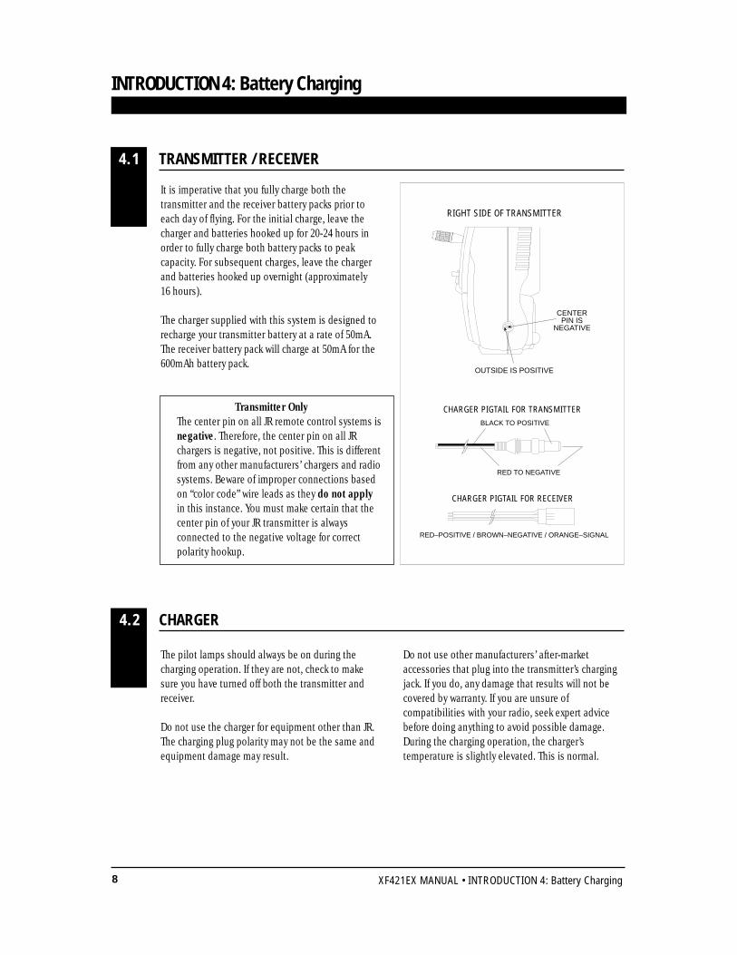
It is imperative that you fully charge both thetransmitter and the receiver battery packs prior toeach day of flying. For the initial charge, leave thecharger and batteries hooked up for 20-24 hours inorder to fully charge both battery packs to peakcapacity. For subsequent charges, leave the chargerand batteries hooked up overnight (approximately 16 hours).
The charger supplied with this system is designed torecharge your transmitter battery at a rate of 50mA.The receiver battery pack will charge at 50mA for the600mAh battery pack.
Transmitter OnlyThe center pin on all JR remote control systems isnegative. Therefore, the center pin on all JR chargers is negative, not positive. This is differentfrom any other manufacturers’ chargers and radiosystems. Beware of improper connections based on “color code” wire leads as they do not applyin this instance. You must make certain that the center pin of your JR transmitter is always connected to the negative voltage for correct polarity hookup.
CENTER PIN IS
NEGATIVE
OUTSIDE IS POSITIVE
RIGHT SIDE OF TRANSMITTER
CHARGER PIGTAIL FOR RECEIVER
CHARGER PIGTAIL FOR TRANSMITTERBLACK TO POSITIVE
RED TO NEGATIVE
RED–POSITIVE / BROWN–NEGATIVE / ORANGE–SIGNAL
TRANSMITTER / RECEIVER4.1
9XF421EX MANUAL • INTRODUCTION 5: Trainer System
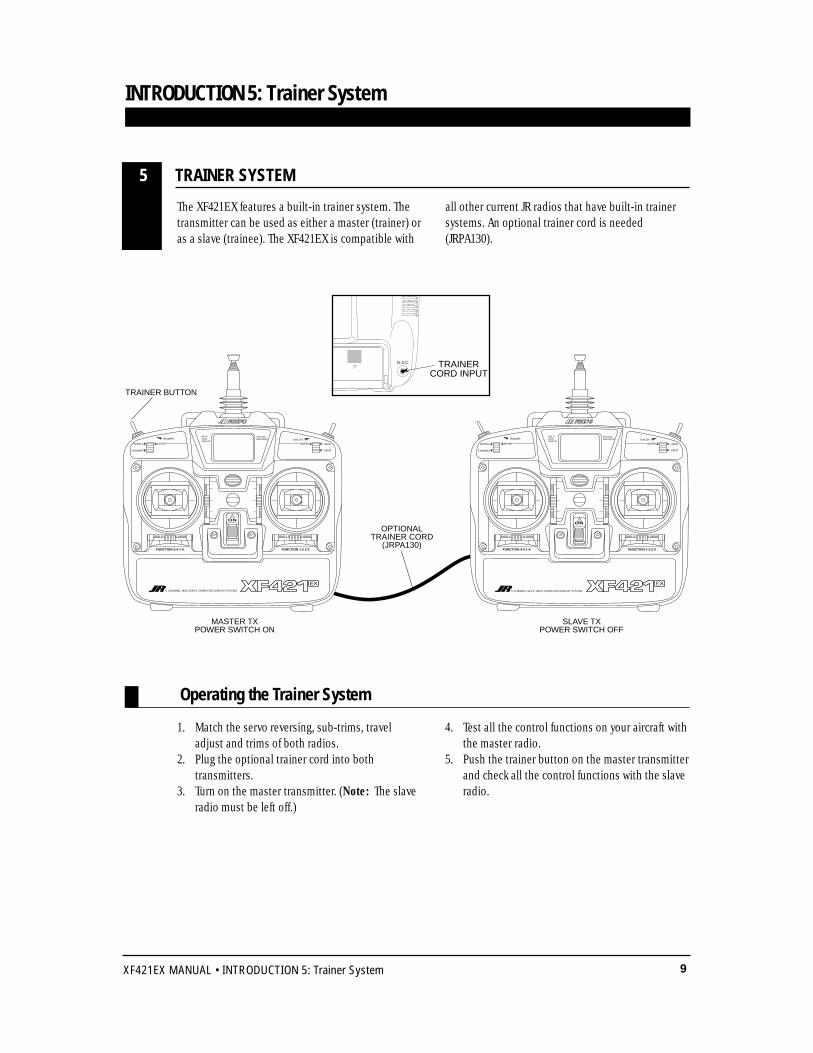
The XF421EX features a built-in trainer system. Thetransmitter can be used as either a master (trainer) oras a slave (trainee). The XF421EX is compatible with
all other current JR radios that have built-in trainersystems. An optional trainer cord is needed(JRPA130).
1. Match the servo reversing, sub-trims, traveladjust and trims of both radios.
2. Plug the optional trainer cord into bothtransmitters.
3. Turn on the master transmitter. (Note: The slave radio must be left off.)
4. Test all the control functions on your aircraft withthe master radio.
5. Push the trainer button on the master transmitterand check all the control functions with the slave radio.
INTRODUCTION 5: Trainer System
TRAINER SYSTEM5
D.S.C. TRAINER CORD INPUT
ON
FUNCTION 3-4 1-4 FUNCTION 1-2 2-3
MULTIDATADISPLAY
VOLTAGEINDICATOR
ON
TRAINER
SCROLL
CHANNEL - DECR
5 CHANNEL MULTI-DATA COMPUTER DISPLAY SYSTEM
FUNCTION 3-4 1-4 FUNCTION 1-2 2-3
MULTIDATADISPLAY
VOLTAGEINDICATOR
OPTIONAL TRAINER CORD
(JRPA130)
MASTER TXPOWER SWITCH ON
SLAVE TXPOWER SWITCH OFF
ENTER
AUX.CH.
+ INCRENTER
5 CHANNEL MULTI-DATA COMPUTER DISPLAY SYSTEM
TRAINER
SCROLL
CHANNEL
ENTER
- DECR
AUX.CH.
+ INCRENTER
TRAINER BUTTON
Operating the Trainer System
10 XF421EX MANUAL • CHAPTER 1: Transmitter Controls
1. THRO Throttle Channel2. AILE Aileron Channel3. ELEV Elevator Channel4. RUDD Rudder Channel5. GEAR Gear Channel
Transmitter Throttle ALTThe throttle ALT function makes the throttle sticktrim active only when the throttle stick is less thanhalf throttle. This gives easy, accurate idleadjustments without affecting the high throttleposition.
RECEIVER CHANNEL ASSIGNMENT/TRANSMITTER THROTTLE ALT1.2
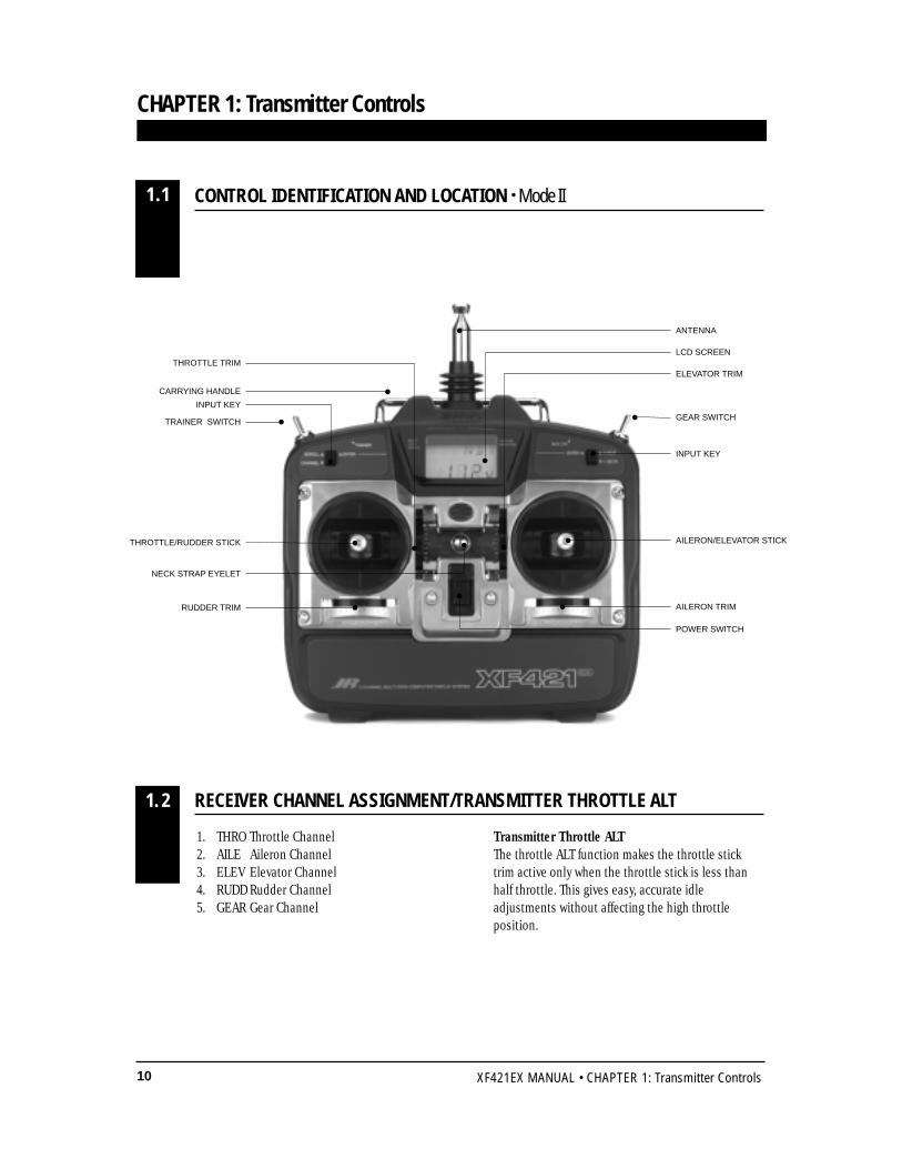
GEAR SWITCH
INPUT KEY
ANTENNA
LCD SCREEN
TRAINER SWITCH
INPUT KEY
AILERON/ELEVATOR STICKTHROTTLE/RUDDER STICK
POWER SWITCH
AILERON TRIM
ELEVATOR TRIMTHROTTLE TRIM
RUDDER TRIM
NECK STRAP EYELET
CARRYING HANDLE
CONTROL IDENTIFICATION AND LOCATION • Mode II
CHAPTER 1: Transmitter Controls
1.1
11XF421EX MANUAL • CHAPTER 1: Transmitter Controls
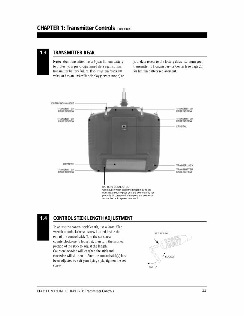
To adjust the control stick length, use a 2mm Allenwrench to unlock the set screw located inside theend of the control stick. Turn the set screwcounterclockwise to loosen it, then turn the knurledportion of the stick to adjust the length.Counterclockwise will lengthen the stick andclockwise will shorten it. After the control stick(s) hasbeen adjusted to suit your flying style, tighten the setscrew.
CONTROL STICK LENGTH ADJUSTMENT1.4
LOOSEN
TIGHTEN
SET SCREW
CHAPTER 1: Transmitter Controls continued
TRANSMITTER REAR1.3
Note: Your transmitter has a 5-year lithium batteryto protect your pre-programmed data against maintransmitter battery failure. If your system reads 0.0volts, or has an unfamiliar display (service mode) or
your data resets to the factory defaults, return yourtransmitter to Horizon Service Center (see page 28)for lithium battery replacement.
BATTERY CONNECTORUse caution when disconnecting/removing thetransmitter battery pack as if the connector is notproperly disconnected, damage to the connectorand/or the radio system can result.
12 XF421EX MANUAL • CHAPTER 1: Transmitter Controls
CHAPTER 1: Transmitter Controls continued
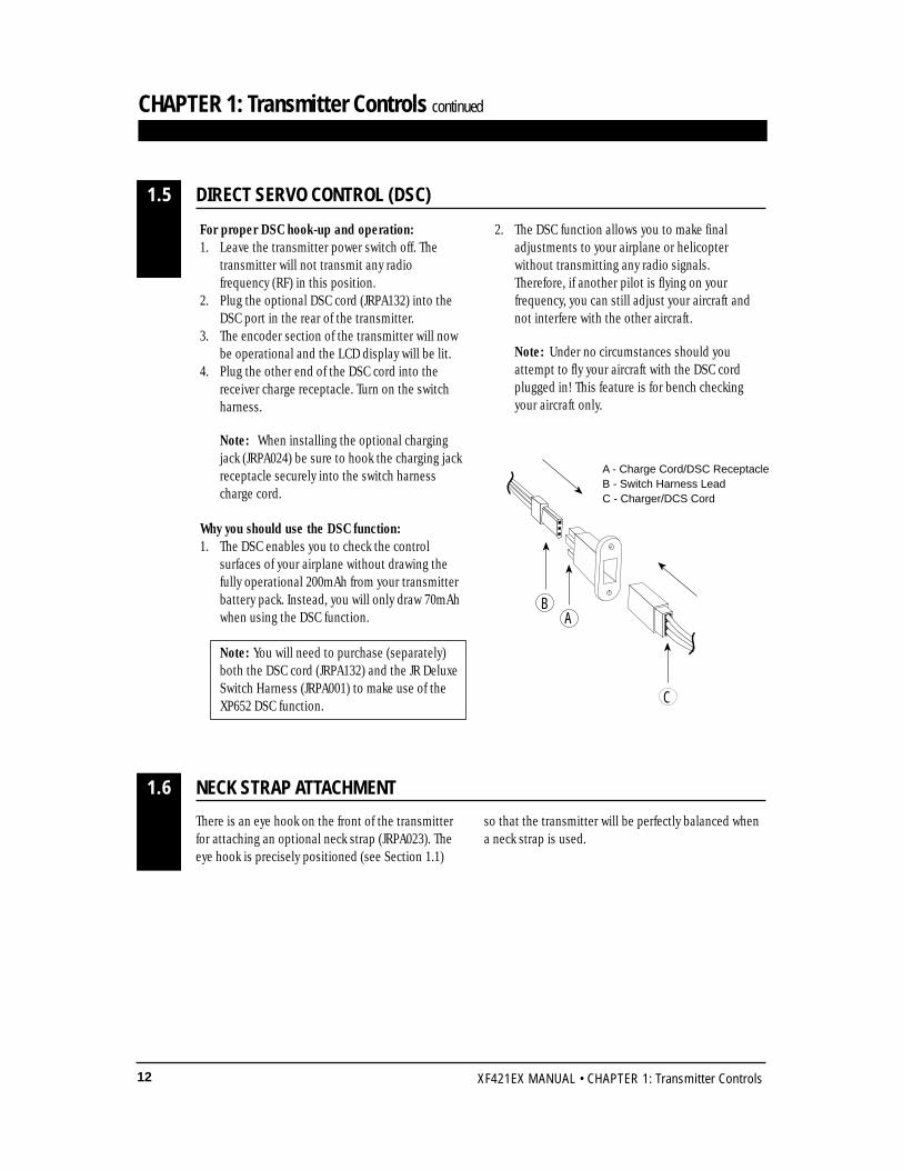
For proper DSC hook-up and operation:1. Leave the transmitter power switch off. The
transmitter will not transmit any radio frequency (RF) in this position.
2. Plug the optional DSC cord (JRPA132) into the DSC port in the rear of the transmitter.
3. The encoder section of the transmitter will now be operational and the LCD display will be lit.
4. Plug the other end of the DSC cord into the receiver charge receptacle. Turn on the switch harness.
Note: When installing the optional charging jack (JRPA024) be sure to hook the charging jack receptacle securely into the switch harness charge cord.
Why you should use the DSC function:1. The DSC enables you to check the control
surfaces of your airplane without drawing the fully operational 200mAh from your transmitter battery pack. Instead, you will only draw 70mAh when using the DSC function.
Note: You will need to purchase (separately) both the DSC cord (JRPA132) and the JR Deluxe Switch Harness (JRPA001) to make use of the XP652 DSC function.
2. The DSC function allows you to make final adjustments to your airplane or helicopter without transmitting any radio signals. Therefore, if another pilot is flying on your frequency, you can still adjust your aircraft and not interfere with the other aircraft.
Note: Under no circumstances should you attempt to fly your aircraft with the DSC cord plugged in! This feature is for bench checking your aircraft only.
There is an eye hook on the front of the transmitterfor attaching an optional neck strap (JRPA023). Theeye hook is precisely positioned (see Section 1.1)
so that the transmitter will be perfectly balanced whena neck strap is used.
DIRECT SERVO CONTROL (DSC)1.5
AB
C
A - Charge Cord/DSC ReceptacleB - Switch Harness LeadC - Charger/DCS Cord
NECK STRAP ATTACHMENT1.6
13XF421EX MANUAL • CHAPTER 2: Connections
It is important to correctly install the radio system inyour model. Please read and carefully follow thesuggestions listed below.
1. For added protection, wrap the Rx and the RxNicad in foam rubber that is at least 1/4” thick.
2. Run the Rx antenna through the fuselage andmake sure it is fully extended. Never cut orbundle your Rx antenna — this will decreaserange and performance.
3. Rubber servo grommets are included with yourradio system and should be installed in the servoflanges. The servos should then be mounted oneither hardwood rails or a plywood tray with themounting screws provided. Do not overtightenthe mounting screws. The flange of the brasseyelets should face down (toward the wood).
4. All servos must be able to move freely over thefull range of their travel. Make sure the linkages
do not impede servo travel. A stalled servo willdrain the battery pack within a few minutes.
5. Before installing servo output arms, make surethe servo is in its neutral position.
6. In the case of gas-powered model aircraft, mountthe receiver power switch on the side of thefuselage opposite the muffler to protect theswitch from exhaust residue. With other types ofmodels, mount the switch in the most convenientplace. Make sure that the switch operates freelyand is capable of traveling its full distance.
7. With your model sitting on the ground and thetransmitter antenna collapsed, check that yoursystem works at a distance of 75 to 100 feet.
If your system stops functioning at a distance thatis shorter than listed above, please contact theHorizon Service Center for further informationprior to flying your model.
INSTALLATION REQUIREMENTS
CHAPTER 2: Connections
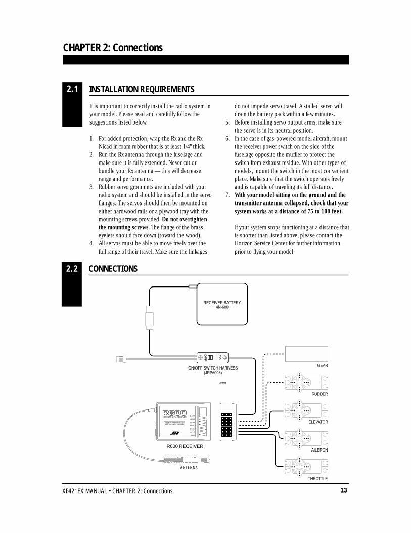
CONNECTIONS2.2
2.1
ON
OF
F
GEAR
RUDDER
ELEVATOR
AILERON
THROTTLE
ON/OFF SWITCH HARNESS(JRPA003)
RECEIVER BATTERY4N-600
226X RECEIVER
NEW ABC & W SYSTEM6 CHANNEL RECEIVER
BATT
AUX 1
GEAR
RUDD
ELEV
AILE
THRO
NER-226XJAPAN REMOTE CONTROL CO., LTD
MADE IN JAPAN
7
2MHz
ANTENNA
BATT
AUX 1
GEAR
RUDD
ELEV
A I L E
THRO
6 CH 72MHz FM RECEIVER
ABC&W INTERFERENCEPROTECTION SYSTEM
R600 RECEIVER

14 XF421EX MANUAL • CHAPTER 3: Key Input and Display / CHAPTER 4: Battery Alarm and Display
Two input keys are located at the upper right and leftface of the XF421EX transmitter. The keys are used toaccess and program the transmitter. Each key can bemoved up or down using your thumbs.
CHAPTER 4: Battery Alarm and Display
CHAPTER 3: Key Input and Display
KEY INPUT AND DISPLAY3
When the transmitter battery drops below 9.0 volts,the display will start to flash BAT and an audiblealarm will sound for 8 beeps. These warnings meanyou should land your aircraft immediately.
Note: During the period that the battery alarmis flashing, the input buttons will notfunction. If you are currently in thefunction mode, the transmitter will exit automatically and return to the normaldisplay (see Section 5.1).
BATTERY ALARM AND DISPLAY4
BAT
8.9V
FLASHING
TRAINER
SCROLL
CHANNEL - DECR
ENTER
AUX.CH.
+ INCRENTER
Left button up........SCROLL — Used to advancethrough the menus.
Left button down...CHANNEL — Used to advancethrough the channels or featuresin a given function.
Right button up........+INCR — Increses value orchanges setting (e.g., ReverseNormal).
Left button down......-DECR — Decreses value orchanges setting. (e.g., ReverseNormal).
15XF421EX MANUAL • CHAPTER 5: Input Mode and Functions
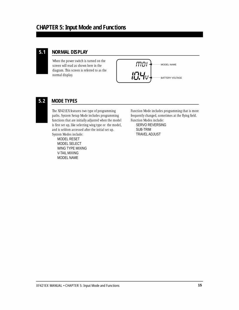
When the power switch is turned on thescreen will read as shown here in thediagram. This screen is referred to as thenormal display.
CHAPTER 5: Input Mode and Functions
I0.4V
MDI MODEL NAME
BATTERY VOLTAGE
NORMAL DISPLAY5.1
The XF421EX features two type of programmingpaths. System Setup Mode includes programmingfunctions that are initially adjusted when the modelis first set up, like selecting wing type or the model,and is seldom accessed after the initial set up.System Modes include:
MODEL RESETMODEL SELECTWING TYPE MIXINGV-TAIL MIXINGMODEL NAME
Function Mode includes programming that is morefrequently changed, sometimes at the flying field.Function Modes include:
SERVO REVERSINGSUB-TRIMTRAVEL ADJUST
MODE TYPES5.2
ON
TRAINER
SCROLL
CHANNEL - DECR
ENTER
AUX.CH.
+ INCRENTER
To enter Systen Setup Modepress both programmingbuttons up and turn on thePower Switch
Power Switch
RST
I
ON
TRAINER
SCROLL
CHANNEL - DECR
ENTER
AUX.CH.
+ INCRENTER
To enter Function Modeturn on the Power Switchand then press bothprogramming buttons up
Power Switch
THR-REV•NORM
16 XF421EX MANUAL • CHAPTER 5: Input Mode and Functions
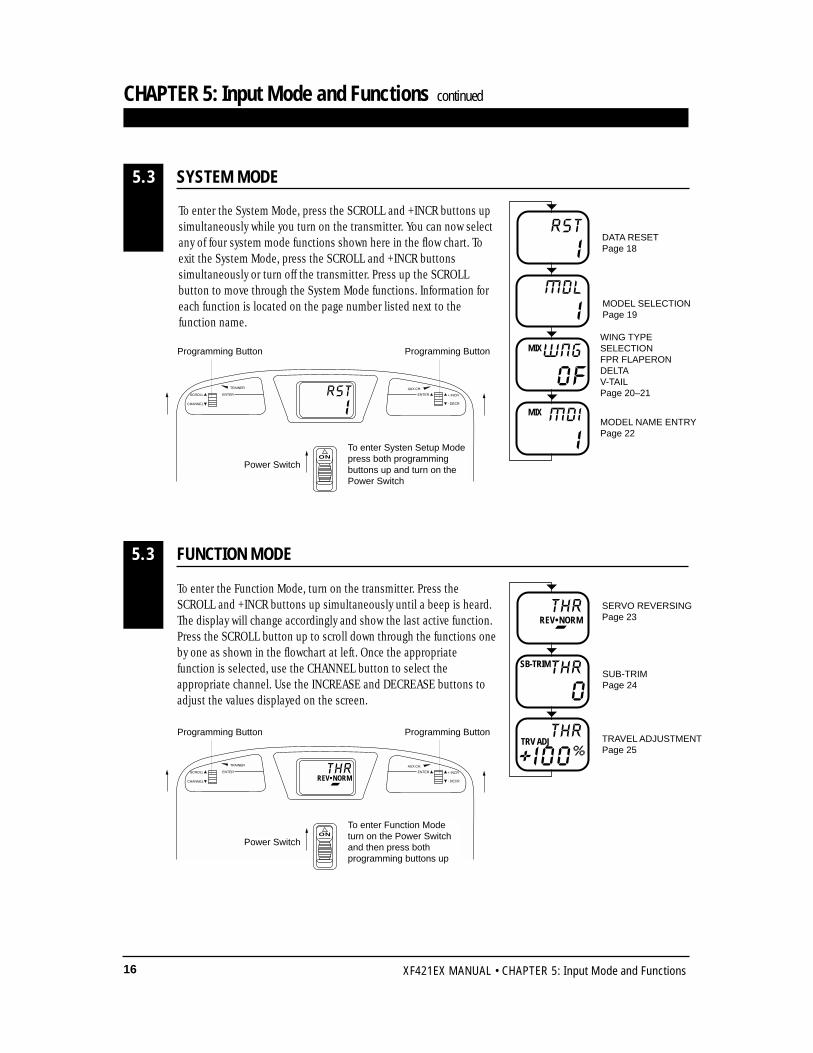
To enter the Function Mode, turn on the transmitter. Press theSCROLL and +INCR buttons up simultaneously until a beep is heard.The display will change accordingly and show the last active function.Press the SCROLL button up to scroll down through the functions oneby one as shown in the flowchart at left. Once the appropriatefunction is selected, use the CHANNEL button to select theappropriate channel. Use the INCREASE and DECREASE buttons toadjust the values displayed on the screen.
CHAPTER 5: Input Mode and Functions continued
FUNCTION MODE5.3
THR
-REV•NORMSERVO REVERSINGPage 23
SUB-TRIMPage 24
TRAVEL ADJUSTMENTPage 25
0THRSB-TRIM
+ I00%
THRTRV ADJ
To enter the System Mode, press the SCROLL and +INCR buttons upsimultaneously while you turn on the transmitter. You can now selectany of four system mode functions shown here in the flow chart. Toexit the System Mode, press the SCROLL and +INCR buttonssimultaneously or turn off the transmitter. Press up the SCROLLbutton to move through the System Mode functions. Information foreach function is located on the page number listed next to thefunction name.
SYSTEM MODE5.3
MODEL NAME ENTRYPage 22
WING TYPE SELECTIONFPR FLAPERONDELTAV-TAILPage 20–21
RSTDATA RESETPage 18
MODEL SELECTIONPage 19I
MDL
OFWNGMIX
I
IMDIMIX
Programming Button Programming Button
Programming Button Programming Button
17XF421EX MANUAL • CHAPTER 6: Functions (System Mode)
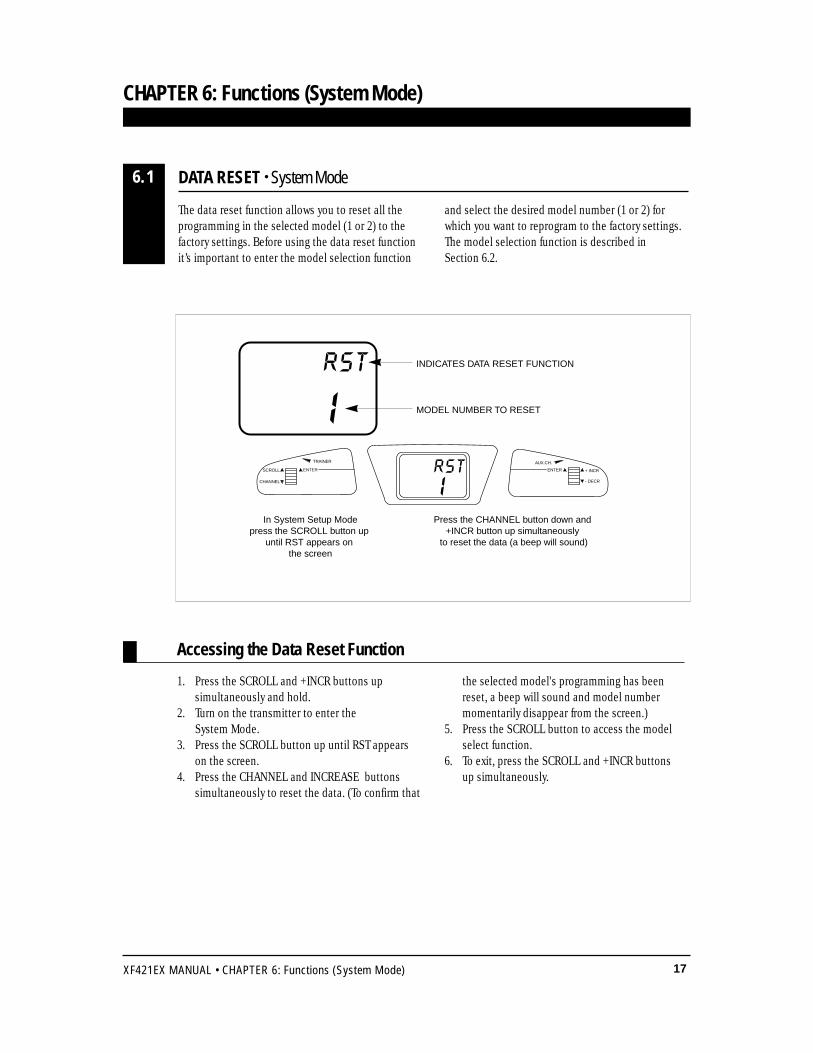
Press the CHANNEL button down and +INCR button up simultaneously
to reset the data (a beep will sound)
In System Setup Modepress the SCROLL button up
until RST appears on the screen
RST INDICATES DATA RESET FUNCTION
MODEL NUMBER TO RESET
Accessing the Data Reset Function
CHAPTER 6: Functions (System Mode)
The data reset function allows you to reset all theprogramming in the selected model (1 or 2) to thefactory settings. Before using the data reset functionit’s important to enter the model selection function
and select the desired model number (1 or 2) forwhich you want to reprogram to the factory settings.The model selection function is described in Section 6.2.
1. Press the SCROLL and +INCR buttons up simultaneously and hold.
2. Turn on the transmitter to enter the System Mode.
3. Press the SCROLL button up until RST appearson the screen.
4. Press the CHANNEL and INCREASE buttonssimultaneously to reset the data. (To confirm that
the selected model's programming has beenreset, a beep will sound and model numbermomentarily disappear from the screen.)
5. Press the SCROLL button to access the modelselect function.
6. To exit, press the SCROLL and +INCR buttons up simultaneously.
DATA RESET • System Mode6.1
TRAINER
SCROLL
CHANNEL - DECR
ENTER
AUX.CH.
+ INCRENTERRSTI
18 XF421EX MANUAL • CHAPTER 6: Functions (System Mode)
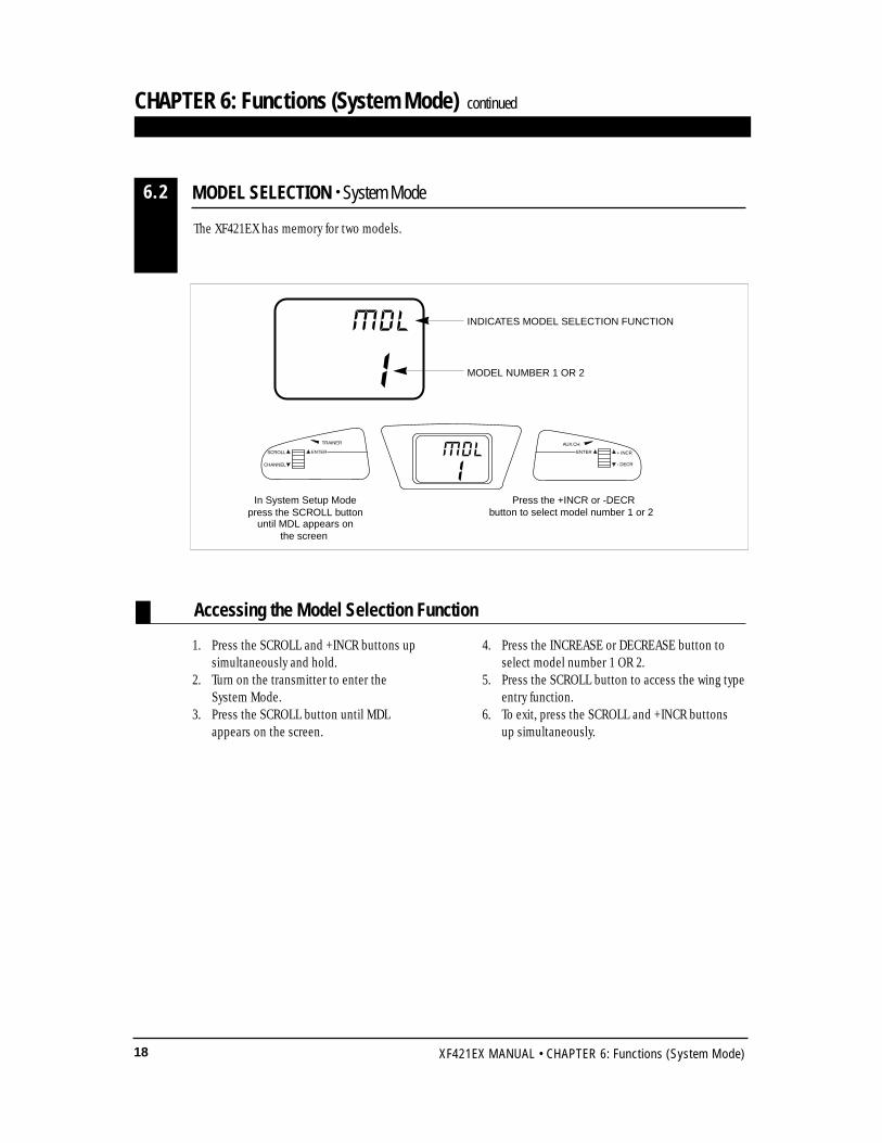
The XF421EX has memory for two models.
1. Press the SCROLL and +INCR buttons up simultaneously and hold.
2. Turn on the transmitter to enter the System Mode.
3. Press the SCROLL button until MDL appears on the screen.
4. Press the INCREASE or DECREASE button toselect model number 1 OR 2.
5. Press the SCROLL button to access the wing typeentry function.
6. To exit, press the SCROLL and +INCR buttons up simultaneously.
Accessing the Model Selection Function
MODEL SELECTION • System Mode6.2
Press the +INCR or -DECRbutton to select model number 1 or 2
In System Setup Modepress the SCROLL button
until MDL appears onthe screen
IMDL INDICATES MODEL SELECTION FUNCTION
MODEL NUMBER 1 OR 2
CHAPTER 6: Functions (System Mode) continued
TRAINER
SCROLL
CHANNEL - DECR
ENTER
AUX.CH.
+ INCRENTERMDLI
19XF421EX MANUAL • CHAPTER 6: Functions (System Mode)
Accessing the Wing Type Selection Function
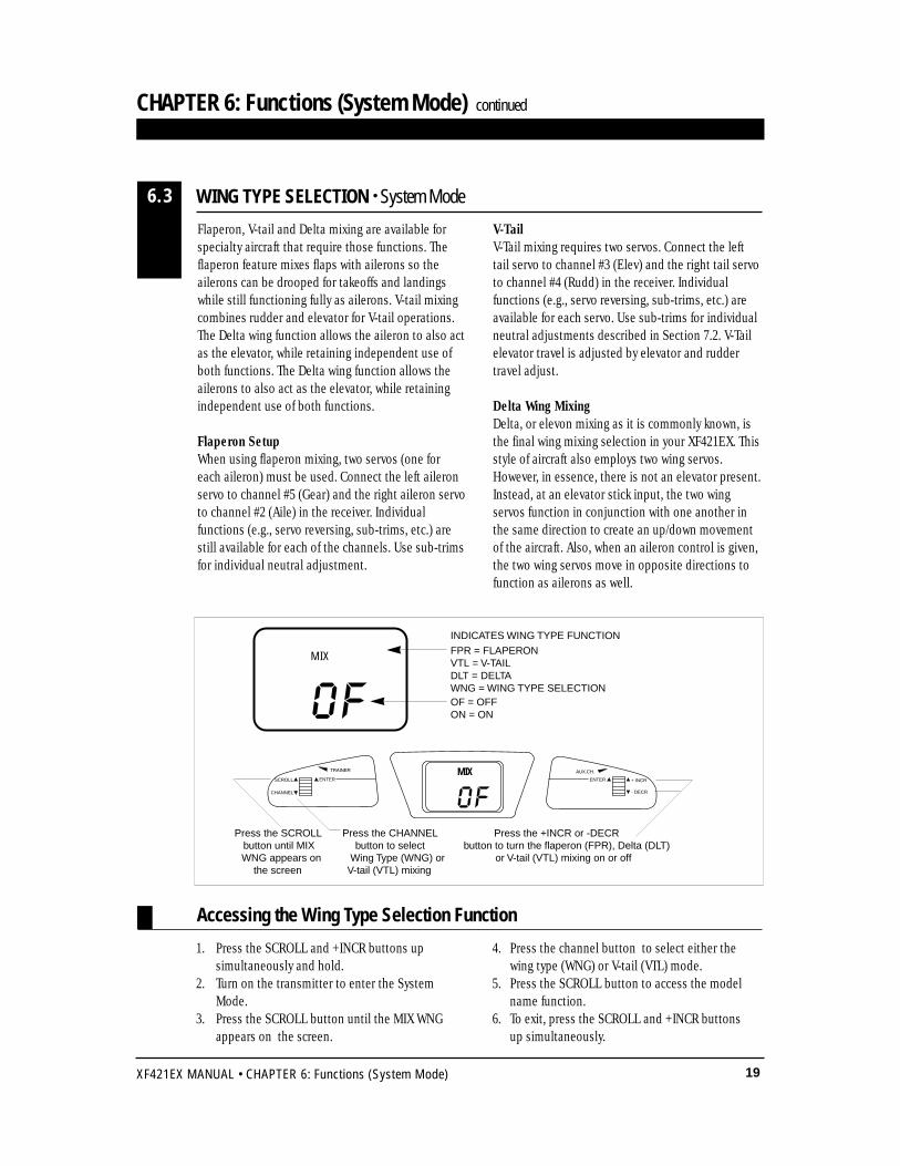
Press the +INCR or -DECRbutton to turn the flaperon (FPR), Delta (DLT)
or V-tail (VTL) mixing on or off
Press the SCROLLbutton until MIXWNG appears on
the screen
Press the CHANNELbutton to select
Wing Type (WNG) or V-tail (VTL) mixing
OF
INDICATES WING TYPE FUNCTION
FPR = FLAPERONVTL = V-TAILDLT = DELTAWNG = WING TYPE SELECTIONOF = OFFON = ON
MIX
Flaperon, V-tail and Delta mixing are available forspecialty aircraft that require those functions. Theflaperon feature mixes flaps with ailerons so theailerons can be drooped for takeoffs and landingswhile still functioning fully as ailerons. V-tail mixingcombines rudder and elevator for V-tail operations.The Delta wing function allows the aileron to also actas the elevator, while retaining independent use ofboth functions. The Delta wing function allows theailerons to also act as the elevator, while retainingindependent use of both functions.
Flaperon SetupWhen using flaperon mixing, two servos (one foreach aileron) must be used. Connect the left aileronservo to channel #5 (Gear) and the right aileron servoto channel #2 (Aile) in the receiver. Individualfunctions (e.g., servo reversing, sub-trims, etc.) arestill available for each of the channels. Use sub-trimsfor individual neutral adjustment.
V-TailV-Tail mixing requires two servos. Connect the lefttail servo to channel #3 (Elev) and the right tail servoto channel #4 (Rudd) in the receiver. Individualfunctions (e.g., servo reversing, sub-trims, etc.) areavailable for each servo. Use sub-trims for individualneutral adjustments described in Section 7.2. V-Tailelevator travel is adjusted by elevator and ruddertravel adjust.
Delta Wing MixingDelta, or elevon mixing as it is commonly known, isthe final wing mixing selection in your XF421EX. Thisstyle of aircraft also employs two wing servos.However, in essence, there is not an elevator present.Instead, at an elevator stick input, the two wingservos function in conjunction with one another inthe same direction to create an up/down movementof the aircraft. Also, when an aileron control is given,the two wing servos move in opposite directions tofunction as ailerons as well.
1. Press the SCROLL and +INCR buttons upsimultaneously and hold.
2. Turn on the transmitter to enter the SystemMode.
3. Press the SCROLL button until the MIX WNGappears on the screen.
4. Press the channel button to select either thewing type (WNG) or V-tail (VTL) mode.
5. Press the SCROLL button to access the modelname function.
6. To exit, press the SCROLL and +INCR buttonsup simultaneously.
WING TYPE SELECTION • System Mode6.3
CHAPTER 6: Functions (System Mode) continued
TRAINER
SCROLL
CHANNEL - DECR
ENTER
AUX.CH.
+ INCRENTER
OFMIX
20 XF421EX MANUAL • CHAPTER 6: Functions (System Mode)
CHAPTER 6: Functions (System Mode) continued
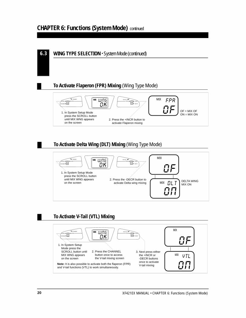
To Activate Flaperon (FPR) Mixing (Wing Type Mode)
To Activate Delta Wing (DLT) Mixing (Wing Type Mode)
1. In System Setup Modepress the SCROLL buttonuntil MIX WNG appearson the screen
2. Press the +INCR button toactivate Flaperon mixing
OFFPRMIX
OF = MIX OFON = MIX ON
OF
ONDLT
MIX
MIX
2. Press the CHANNELbutton once to accessthe V-tail mixing screen
DELTA WINGMIX ON
OF
ONVTL
MIX
MIX
To Activate V-Tail (VTL) Mixing
Note: It is also possible to activate both the flaperon (FPR) and V-tail functions (VTL) to work simultaneously.
WING TYPE SELECTION • System Mode (continued)6.3
TRAINER
SCROLL
CHANNEL - DECR
ENTER
AUX.CH.
+ INCRENTER
1. In System Setup Modepress the SCROLL buttonuntil MIX WNG appearson the screen
2. Press the -DECR button toactivate Delta wing mixing
TRAINER
SCROLL
CHANNEL - DECR
ENTER
AUX.CH.
+ INCRENTER
1. In System SetupMode press theSCROLL button untilMIX WNG appearson the screen
3. Next press eitherthe +INCR or -DECR buttonsonce to activate V-tail mixing
TRAINER
SCROLL
CHANNEL - DECR
ENTER
AUX.CH.
+ INCRENTER
OKWNGMIX
OKWNGMIX
OKWNGMIX
21XF421EX MANUAL • CHAPTER 6: Functions (System Mode)
CHAPTER 6: Functions (System Mode) continued
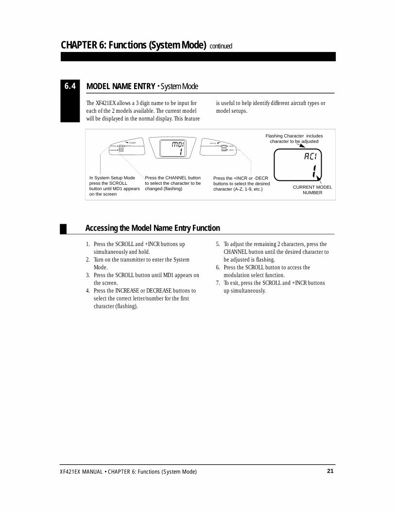
1. Press the SCROLL and +INCR buttons upsimultaneously and hold.
2. Turn on the transmitter to enter the SystemMode.
3. Press the SCROLL button until MD1 appears onthe screen.
4. Press the INCREASE or DECREASE buttons to select the correct letter/number for the first character (flashing).
5. To adjust the remaining 2 characters, press the CHANNEL button until the desired character tobe adjusted is flashing.
6. Press the SCROLL button to access themodulation select function.
7. To exit, press the SCROLL and +INCR buttonsup simultaneously.
Accessing the Model Name Entry Function
Press the CHANNEL buttonto select the character to bechanged (flashing)
Press the +INCR or -DECRbuttons to select the desiredcharacter (A-Z, 1-9, etc.)
Flashing Character includescharacter to be adjusted
CURRENT MODELNUMBER
IAC I
In System Setup Modepress the SCROLLbutton until MD1 appearson the screen
The XF421EX allows a 3 digit name to be input foreach of the 2 models available. The current modelwill be displayed in the normal display. This feature
is useful to help identify different aircraft types ormodel setups.
MODEL NAME ENTRY • System Mode6.4
TRAINER
SCROLL
CHANNEL - DECR
ENTER
AUX.CH.
+ INCRENTERMDII
22 XF421EX MANUAL • CHAPTER 7: Functions (Function Mode)
CHAPTER 7: Functions (Function Mode)
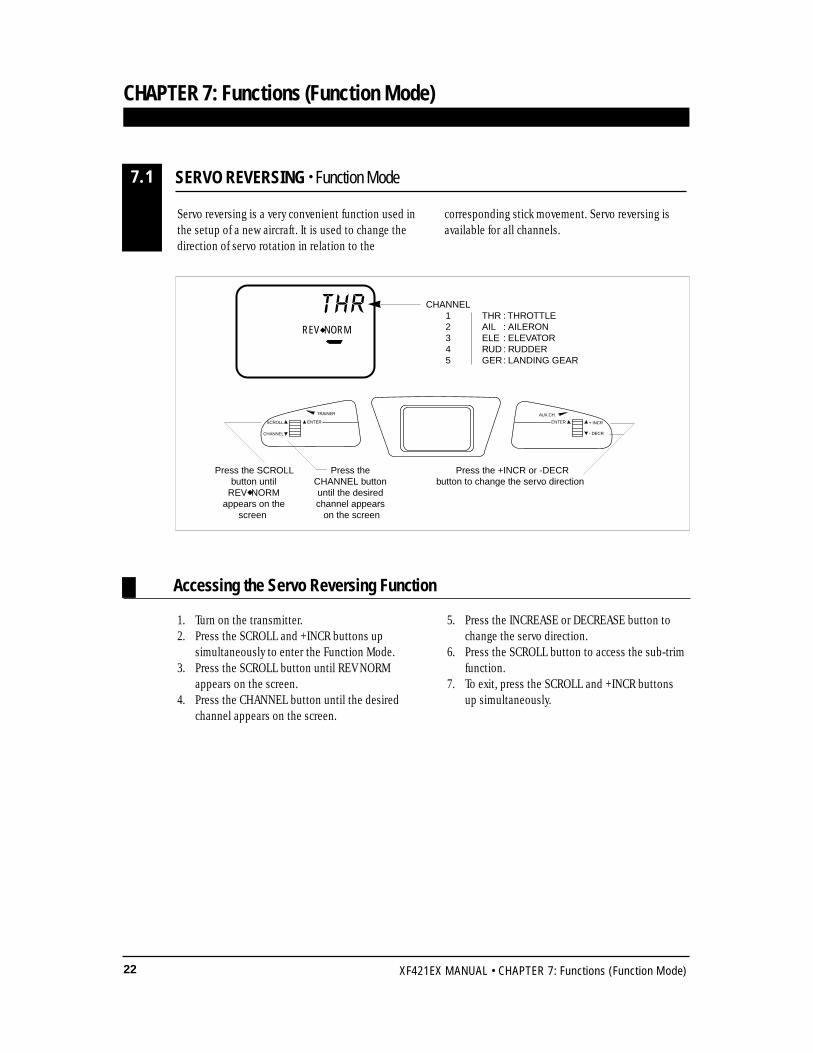
Servo reversing is a very convenient function used inthe setup of a new aircraft. It is used to change thedirection of servo rotation in relation to the
corresponding stick movement. Servo reversing isavailable for all channels.
1. Turn on the transmitter.2. Press the SCROLL and +INCR buttons up
simultaneously to enter the Function Mode.3. Press the SCROLL button until REV NORM
appears on the screen.4. Press the CHANNEL button until the desired
channel appears on the screen.
5. Press the INCREASE or DECREASE button tochange the servo direction.
6. Press the SCROLL button to access the sub-trimfunction.
7. To exit, press the SCROLL and +INCR buttons up simultaneously.
Accessing the Servo Reversing Function
SERVO REVERSING • Function Mode7.1
THR : THROTTLEAIL : AILERONELE : ELEVATORRUD : RUDDERGER: LANDING GEAR
CHANNEL12345
REV◆ NORM
THR
Press the +INCR or -DECRbutton to change the servo direction
Press the SCROLLbutton until
REV◆ NORMappears on the
screen
Press theCHANNEL buttonuntil the desiredchannel appears on the screen
TRAINER
SCROLL
CHANNEL - DECR
ENTER
AUX.CH.
+ INCRENTER

23XF421EX MANUAL • CHAPTER 7: Functions (Function Mode)
Accessing the Sub-Trim Function
Press the +INCR or -DECRbutton to adjust the sub-trim value
Press the SCROLLbutton untilSB-TRIM
appears on thescreen
Press theCHANNEL buttonuntil the desiredchannel appearson the screen
SB-TRIM T H R
0
THR : THROTTLEAIL : AILERONELE : ELEVATORRUD : RUDDERGER: LANDING GEAR
CHANNEL12345
INDICATES THE SUB-TRIM FUNCTION
SUB-TRIM VALUE (±125)
Sub-trim is an electronic trim that is available foreach of the 5 channels. Sub-trim is particularly usefulas it allows the mechanical trim levers to be returnedto their neutral positions by adjusting /changing theservo’s neutral position electronically, without theneed to mechanically adjust the specific controllinkage. This allows the same mechanical trim leversettings between the two models you can control
with this radio system. Sub-trim can also allowadditional trim travel when mechanical trims do notprovide enough movement.
Note: It is recommended to use as little sub-trim aspossible for adjustment. If more that 20–30 pointsare required, is it suggested that a mechanicallinkage adjustment be performed.
1. Turn on the transmitter.2. Press the SCROLL and +INCR buttons up
simultaneously to enter the Function Mode.3. Press the SCROLL button until SB-Trim appears
on the screen.4. Press the CHANNEL button until the desired
channel appears on the screen.
5. Press the +INCR or -DECR button to establishthe desired amount of sub-trim.
6. Press the SCROLL button to access the traveladjustment function.
7. To exit, press the SCROLL and +INCR buttons up simultaneously.
SUB-TRIM • Function Mode7.2
CHAPTER 7: Functions (Function Mode) continued
TRAINER
SCROLL
CHANNEL - DECR
ENTER
AUX.CH.
+ INCRENTER
24 XF421EX MANUAL • CHAPTER 7: Functions (Function Mode)
CHAPTER 7: Functions (Function Mode) continued
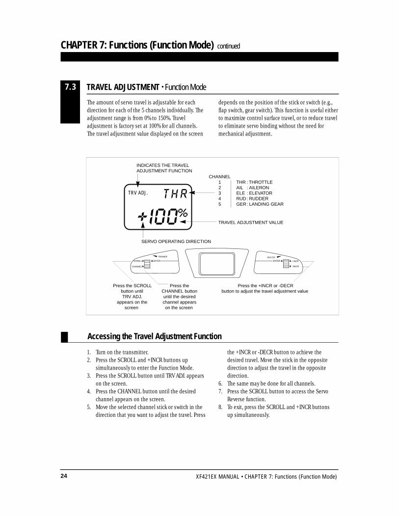
The amount of servo travel is adjustable for eachdirection for each of the 5 channels individually. Theadjustment range is from 0% to 150%. Traveladjustment is factory set at 100% for all channels.The travel adjustment value displayed on the screen
depends on the position of the stick or switch (e.g.,flap switch, gear switch). This function is useful eitherto maximize control surface travel, or to reduce travelto eliminate servo binding without the need formechanical adjustment.
1. Turn on the transmitter.2. Press the SCROLL and +INCR buttons up
simultaneously to enter the Function Mode.3. Press the SCROLL button until TRV ADJ. appears
on the screen.4. Press the CHANNEL button until the desired
channel appears on the screen.5. Move the selected channel stick or switch in the
direction that you want to adjust the travel. Press
the +INCR or -DECR button to achieve thedesired travel. Move the stick in the oppositedirection to adjust the travel in the oppositedirection.
6. The same may be done for all channels.7. Press the SCROLL button to access the Servo
Reverse function.8. To exit, press the SCROLL and +INCR buttons
up simultaneously.
Press the +INCR or -DECRbutton to adjust the travel adjustment value
Press the SCROLLbutton untilTRV ADJ.
appears on thescreen
Press theCHANNEL buttonuntil the desiredchannel appearson the screen
TRV ADJ. T H R
+ I00%
THR : THROTTLEAIL : AILERONELE : ELEVATORRUD : RUDDERGER: LANDING GEAR
CHANNEL12345
INDICATES THE TRAVELADJUSTMENT FUNCTION
TRAVEL ADJUSTMENT VALUE
SERVO OPERATING DIRECTION
Accessing the Travel Adjustment Function
TRAVEL ADJUSTMENT • Function Mode7.3
TRAINER
SCROLL
CHANNEL - DECR
ENTER
AUX.CH.
+ INCRENTER
25XF421EX MANUAL • CHAPTER 8: Data Sheet
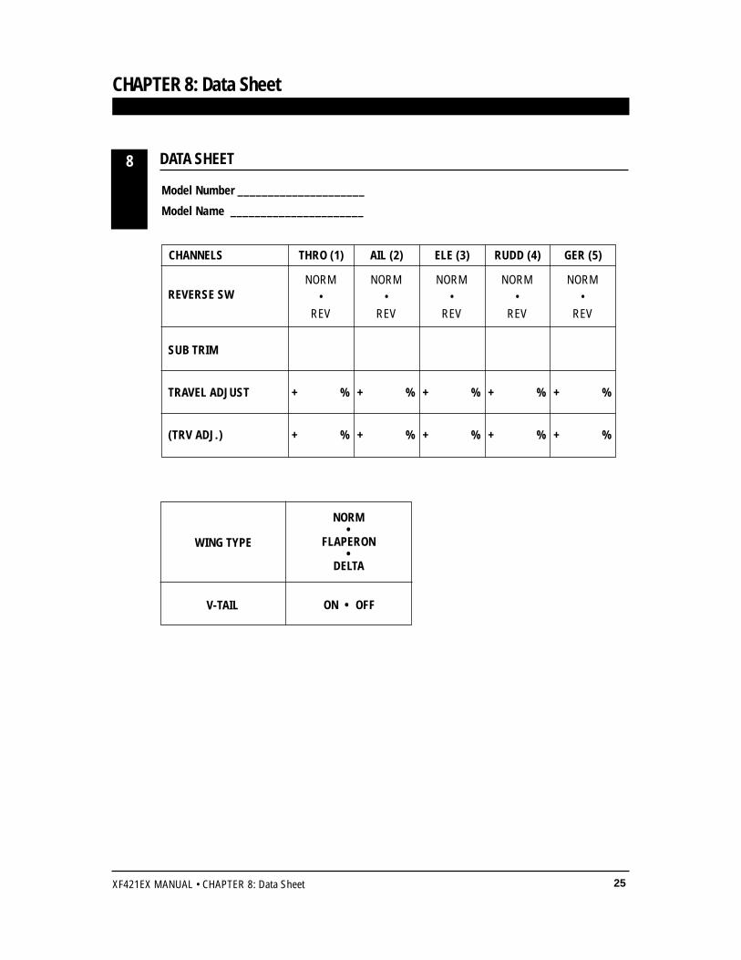
DATA SHEET
CHAPTER 8: Data Sheet
8
NORM NORM NORM NORM NORM• • • • •
REV REV REV REV REV
SUB TRIM
TRAVEL ADJUST + % + % + % + % + %
(TRV ADJ.) + % + % + % + % + %
REVERSE SW
CHANNELS THRO (1) AIL (2) ELE (3) RUDD (4) GER (5)
WING TYPE
V-TAIL ON • OFF
NORM•
FLAPERON•
DELTA
Model Number _____________________
Model Name ______________________
26 XF421EX MANUAL • IMPORTANT INFORMATION
IMPORTANT INFORMATION
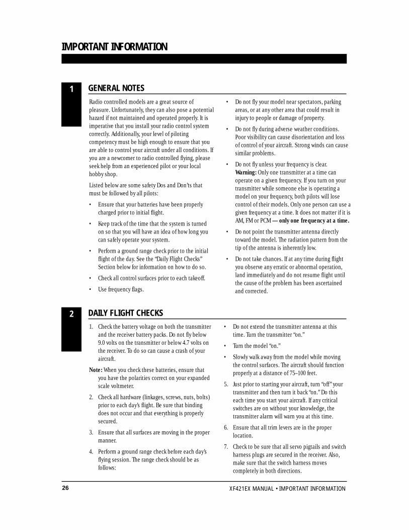
Radio controlled models are a great source ofpleasure. Unfortunately, they can also pose a potentialhazard if not maintained and operated properly. It isimperative that you install your radio control systemcorrectly. Additionally, your level of pilotingcompetency must be high enough to ensure that youare able to control your aircraft under all conditions. Ifyou are a newcomer to radio controlled flying, pleaseseek help from an experienced pilot or your localhobby shop.
Listed below are some safety Dos and Don’ts thatmust be followed by all pilots:
• Ensure that your batteries have been properlycharged prior to initial flight.
• Keep track of the time that the system is turnedon so that you will have an idea of how long youcan safely operate your system.
• Perform a ground range check prior to the initialflight of the day. See the “Daily Flight Checks”Section below for information on how to do so.
• Check all control surfaces prior to each takeoff.
• Use frequency flags.
• Do not fly your model near spectators, parkingareas, or at any other area that could result ininjury to people or damage of property.
• Do not fly during adverse weather conditions.Poor visibility can cause disorientation and loss of control of your aircraft. Strong winds can causesimilar problems.
• Do not fly unless your frequency is clear. Warning: Only one transmitter at a time canoperate on a given frequency. If you turn on yourtransmitter while someone else is operating amodel on your frequency, both pilots will losecontrol of their models. Only one person can use agiven frequency at a time. It does not matter if it isAM, FM or PCM — only one frequency at a time.
• Do not point the transmitter antenna directlytoward the model. The radiation pattern from thetip of the antenna is inherently low.
• Do not take chances. If at any time during flightyou observe any erratic or abnormal operation,land immediately and do not resume flight untilthe cause of the problem has been ascertainedand corrected.
1. Check the battery voltage on both the transmitterand the receiver battery packs. Do not fly below9.0 volts on the transmitter or below 4.7 volts onthe receiver. To do so can cause a crash of youraircraft.
Note: When you check these batteries, ensure thatyou have the polarities correct on your expandedscale voltmeter.
2. Check all hardware (linkages, screws, nuts, bolts)prior to each day’s flight. Be sure that bindingdoes not occur and that everything is properlysecured.
3. Ensure that all surfaces are moving in the propermanner.
4. Perform a ground range check before each day’sflying session. The range check should be asfollows:
• Do not extend the transmitter antenna at thistime. Turn the transmitter “on.”
• Turn the model “on.”
• Slowly walk away from the model while movingthe control surfaces. The aircraft should functionproperly at a distance of 75–100 feet.
5. Just prior to starting your aircraft, turn “off ” yourtransmitter and then turn it back “on.” Do thiseach time you start your aircraft. If any criticalswitches are on without your knowledge, thetransmitter alarm will warn you at this time.
6. Ensure that all trim levers are in the properlocation.
7. Check to be sure that all servo pigtails and switchharness plugs are secured in the receiver. Also,make sure that the switch harness movescompletely in both directions.
GENERAL NOTES1
DAILY FLIGHT CHECKS2
27XF421EX MANUAL • WARRANTY AND SERVICE IMFORMATION
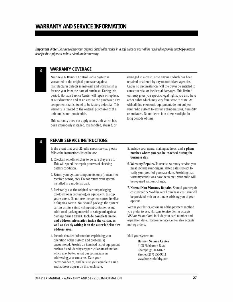
Important Note: Be sure to keep your original dated sales receipt in a safe place as you will be required to provide proof-of-purchasedate for the equipment to be serviced under warranty.
WARRANTY AND SERVICE INFORMATION
WARRANTY COVERAGE
REPAIR SERVICE INSTRUCTIONS
Your new JR Remote Control Radio System iswarranted to the original purchaser againstmanufacturer defects in material and workmanshipfor one year from the date of purchase. During thisperiod, Horizon Service Center will repair or replace,at our discretion and at no cost to the purchaser, anycomponent that is found to be factory defective. Thiswarranty is limited to the original purchaser of theunit and is not transferable.
This warranty does not apply to any unit which hasbeen improperly installed, mishandled, abused, or
damaged in a crash, or to any unit which has beenrepaired or altered by any unauthorized agencies.Under no circumstances will the buyer be entitled toconsequential or incidental damages. This limitedwarranty gives you specific legal rights; you also haveother rights which may vary from state to state. Aswith all fine electronic equipment, do not subjectyour radio system to extreme temperatures, humidityor moisture. Do not leave it in direct sunlight forlong periods of time.
In the event that your JR radio needs service, pleasefollow the instructions listed below:
1. Check all on/off switches to be sure they are off.This will speed the repair process of checkingbattery condition.
2. Return your system components only (transmitter,receiver, servos, etc). Do not return your systeminstalled in a model aircraft.
3. Preferably, use the original carton/packaging(molded foam container), or equivalent, to shipyour system. Do not use the system carton itself asa shipping carton. You should package the systemcarton within a sturdy shipping container usingadditional packing material to safeguard againstdamage during transit. Include complete nameand address information inside the carton, aswell as clearly writing it on the outer label/returnaddress area.
4. Include detailed information explaining youroperation of the system and problem(s)encountered. Provide an itemized list of equipmentenclosed and identify any particular area/functionwhich may better assist our technicians inaddressing your concerns. Date yourcorrespondence, and be sure your complete nameand address appear on this enclosure.
5. Include your name, mailing address, and a phonenumber where you can be reached during thebusiness day.
6. Warranty Repairs. To receive warranty service, youmust include your original dated sales receipt toverify your proof-of-purchase date. Providing thatwarranty conditions have been met, your radio willbe repaired without charge.
7. Normal Non-Warranty Repairs. Should your repaircost exceed 50% of the retail purchase cost, you willbe provided with an estimate advising you of youroptions.
Within your letter, advise us of the payment methodyou prefer to use. Horizon Service Center acceptsVISA or MasterCard. Include your card number andexpiration date. Horizon Service Center also acceptsmoney orders.
Mail your system to:
Horizon Service Center4105 Fieldstone RoadChampaign, IL 61822Phone: (217) 355-9511www.horizonhobby.com
3
4
28 XF421EX MANUAL • FREQUENCY CHART
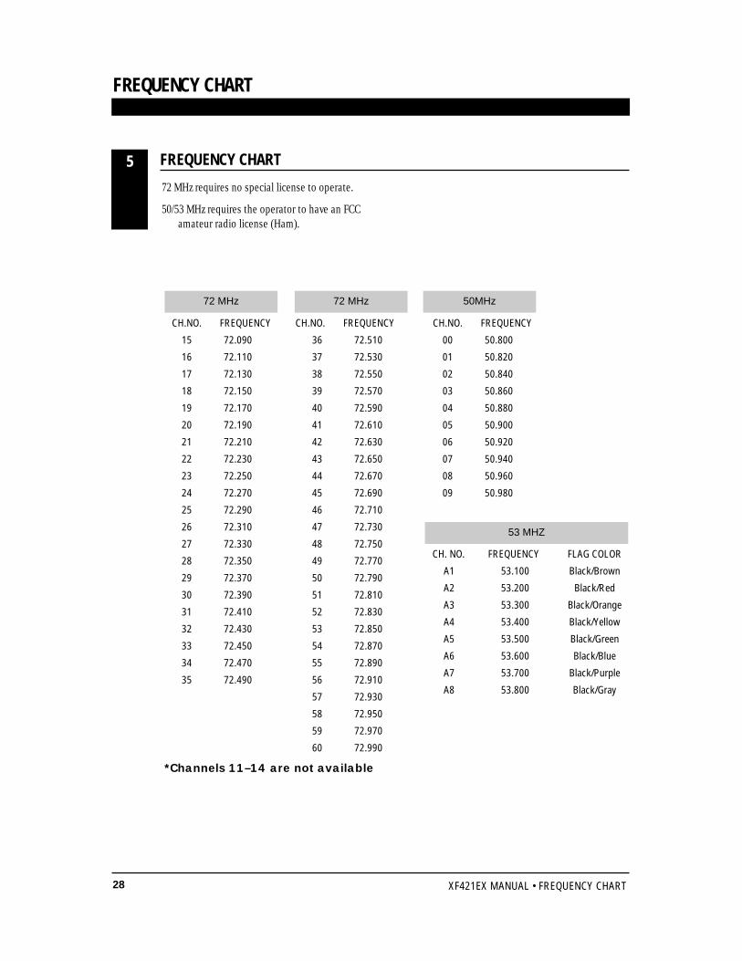
72 MHz requires no special license to operate.
50/53 MHz requires the operator to have an FCCamateur radio license (Ham).
CH.NO. FREQUENCY
15 72.090
16 72.110
17 72.130
18 72.150
19 72.170
20 72.190
21 72.210
22 72.230
23 72.250
24 72.270
25 72.290
26 72.310
27 72.330
28 72.350
29 72.370
30 72.390
31 72.410
32 72.430
33 72.450
34 72.470
35 72.490
CH.NO. FREQUENCY
36 72.510
37 72.530
38 72.550
39 72.570
40 72.590
41 72.610
42 72.630
43 72.650
44 72.670
45 72.690
46 72.710
47 72.730
48 72.750
49 72.770
50 72.790
51 72.810
52 72.830
53 72.850
54 72.870
55 72.890
56 72.910
57 72.930
58 72.950
59 72.970
60 72.990
CH.NO. FREQUENCY
00 50.800
01 50.820
02 50.840
03 50.860
04 50.880
05 50.900
06 50.920
07 50.940
08 50.960
09 50.980
72 MHz 50MHz
CH. NO. FREQUENCY FLAG COLOR
A1 53.100 Black/Brown
A2 53.200 Black/Red
A3 53.300 Black/Orange
A4 53.400 Black/Yellow
A5 53.500 Black/Green
A6 53.600 Black/Blue
A7 53.700 Black/Purple
A8 53.800 Black/Gray
53 MHZ
FREQUENCY CHART5
72 MHz
FREQUENCY CHART
*Channels 11–14 are not available

NOTES

NOTES


DISTRIBUTED EXCLUSIVELY BY HORIZON HOBBY DISTRIBUTORS CHAMPAIGN, IL 61822www.horizonhobby.com
© 1999 Horizon Hobby Distributors, Inc. All Rights Reserved.
®