Embed Size (px)
Citation preview
5 Insulation
M. Donabedian,* D. G. Gilmore,* J. W. Stultz, t G. T. Tsuyuki, t and E. I. Lin t
Introduction
Multilayer insulation (MLI) and single-layer radiation barriers are among the most common thermal-control elements on spacecraft. MLI blankets prevent both excessive heat loss from a component and excessive heating from environmental fluxes, rocket plumes, and other sources. Most spacecraft flown today are covered with MLI blankets, with cutouts provided for areas where radiators reject inter- nally generated waste heat. MLI blankets are also typically used to protect internal propellant tanks, propellant lines, solid rocket motors, and cryogenic dewars. Sin- gle-layer radiation barriers are sometimes used in place of MLI where less thermal lsoJauon 1s requlreo, since Jlgnter and " " ,~ppnca- cheaper to manmacture. mey are tions requiting insulation under atmospheric conditions generally use foam, batt, and aerogel materials because MLI is not very effective in the presence of a gas. See Chapter 3 for specific examples of how insulation is used in typical thermal designs.
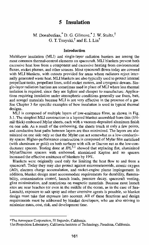
MLI is composed of multiple layers of low-emittance films, as shown in Fig. 5.1. The simplest MLI construction is a layered blanket assembled from thin (1/4- mil thick) embossed Mylar sheets, each with a vacuum-deposited aluminum finish on one side. As a result of the embossing, the sheets touch at only a few points, and conductive heat paths between layers are thus minimized. The layers are alu- minized on one side only so that the Mylar can act somewhat as a low-conductiv- ity spacer. Higher-performance construction is composed of Mylar film metalized (with aluminum or gold) on both surfaces with silk or Dacron net as the low-con- ductance spacers. Testing done at JPL 51 showed that replacing fiat, aluminized Mylar/Dacron spacers with embossed, aluminized Kapton and no spacers increased the effective emittance of blankets by 19%.
Blankets were originally used only for limiting the heat flow to and from a spacecraft. Today they may also protect against micrometeoroids, atomic oxygen (AO), electron charge accumulation, and rocket-engine plume impingement. In addition, blanket design must accommodate requirements for durability, flamma- bility, contamination control, launch loads, pressure decay, spacecraft venting, glint minimization, and restrictions on magnetic materials. Because most launch sites are near beaches (or even in the middle of the ocean, as in the case of Sea- Launch), exposure to salt spray and other corrosive agents is possible, so blanket design must take that exposure into account. All of these functions and design requirements must be addressed by blanket developers, who are also striving to minimize mass, cost, risk, and development time.
*The Aerospace Corporation, E1 Segundo, California. tJet Propulsion Laboratory, California Institute of Technology, Pasadena, California.
161
Outer cover \ Light bloc~,,~
(in necessary Metalized reflector
Netting spacer *= l=~nn~Arl/~
(15 to 20 reflector spacer layers, tott
Metalized reflector Netting spacer
Inner cover Structure
Note: Details and features are shown for illustration and will vary with actual design and installation.
Fig. 5.1. Composition of a typical MLI blanket. (Courtesy NASA 5"2)
162 Insulation
Blanket Performance
Heat transfer through MLI is a combination of radiation, solid conduction, and, under atmospheric conditions, gaseous conduction. These forms of heat transfer are minimized in different ways. Radiative heat transfer is minimized by interpos- ing as many enclosing reflective surfaces (metalized sheets) as is practical between the object being insulated and its surroundings. Solid-conduction heat transfer is minimized by keeping the density of the low-conductance spacers between the reflective surfaces as low as possible and making the blanket "fluffy" to minimize contact between layers. Gaseous-conduction heat transfer is mini- mized by allowing the insulation to vent to space after the vehicle is launched or by using the insulation in an evacuated wall, such as the space between a cryo- genic pressure vessel and the external vacuum-jacket shell.
Because these heat-transfer mechanisms operate simultaneously and interact with each other, the thermal conductivity of an insulation system is not strictly definable, analytically, in terms of variables such as temperature, density, or phys- ical properties of the component materials. A useful technique is to refer to either an apparent thermal conductivity, Keff, or an effective emittance, e* (informally known as "E-star"), through the blanket. Both values can be derived experimen- tally during steady-state heat transfer.
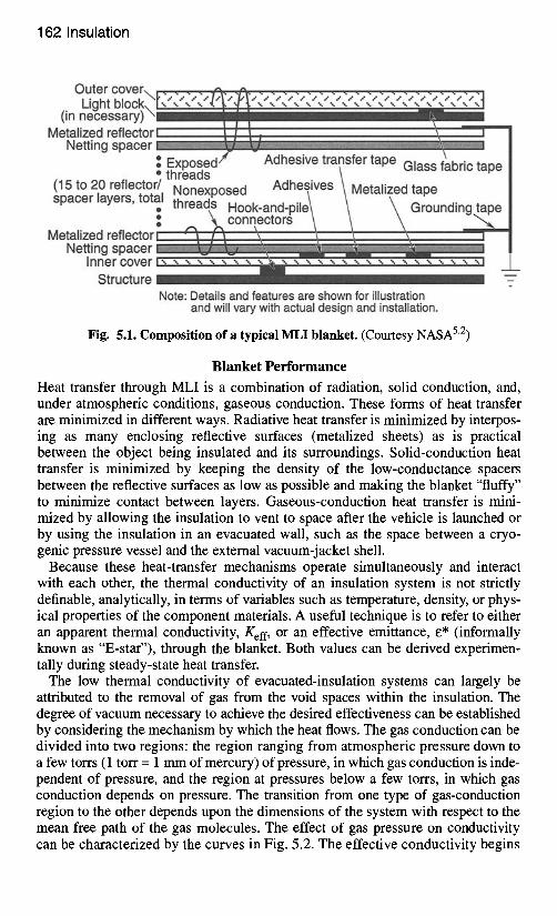
The low thermal conductivity of evacuated-insulation systems can largely be attributed to the removal of gas from the void spaces within the insulation. The degree of vacuum necessary to achieve the desired effectiveness can be established by considering the mechanism by which the heat flows. The gas conduction can be divided into two regions: the region ranging from atmospheric pressure down to a few torrs (1 torr = 1 mm of mercury) of pressure, in which gas conduction is inde- pendent of pressure, and the region at pressures below a few torrs, in which gas conduction depends on pressure. The transition from one type of gas-conduction region to the other depends upon the dimensions of the system with respect to the mean free path of the gas molecules. The effect of gas pressure on conductivity can be characterized by the curves in Fig. 5.2. The effective conductivity begins
Blanket Performance 163
1.0
0.1
5" E o
E v
.> "5 := 0.01 "13 t - O O
tl:l E L _
e- I---
0.001
I I I I I I I I I Note: d = Distance between confining surfaces
a = Accommodation coefficient (dimensionless)
Crinkled, aluminzed • polyester in air ' -
-° Aluminized polyester and foam in helium | 15 Ib ft -3 -
glass wool in air -
Theoretical curve ~ m . ~ / / / t d = 0.030 in. a=0.4
l J i . _ i l
Aluminum/~,,j~~" I ~/~~Aluminum and shields and fiberglass in helium
wool glass Tcotd = -423 ° F (20 K) in air, /
k~ / . ~ / ~ / / Tempered aluminum and vinyl- - ,, / • / ' i / coated fiberglass screen in helium
Tcold =-320 ° F (77 K)
1.0
0 . 1 "~" t--
, i , -
o
5" t - :3
..Q
0=0! >
o :3
"13 t - O o
tl:l E L _
e- l--
0.001
"F _,,- . / A , , ~ , ~ y ~ "t neorettcatd = 0.001 curVein.
_ .~_.~ , , - ,~ a = 0.4 0.0001 ~ I I I I I I I 0.0001
10 -6 10 -5 10 -4 10 -3 10 -2 10-1 1 10 102 103 104 Gas pressure (Torr)
Fig. 5.2. Effect of gas pressure on thermal conductivity.
to decrease sharply between 1 and 10 torr until about 10 -4 t o 10 -5 torr, where the heat conducted by the gas is only a small portion of the residual heat transfer. A finite value of effective thermal conductivity remains at lower pressures as a result of heat transfer by solid conduction and radiation between the elements of the insulation.
In theory, for highly evacuated MLI systems (i.e., systems with gas pressures of 10 -5 torr or less), the emittance 13 for a blanket of N noncontacting layers of emis- sivities 13] and 13 2 o n opposite sides is computed as
1 l 1 ) e = 1 + 1 _ 1 N+ 1 " (5.1)
81 8 2
164 Insulation
In practice, the effective emittance of an MLI blanket is generally derived from experimental tests at gas pressure of 10 -5 torr or less calculated from
e = Q (5.2) A ~ ( T 4 - r c 4 ) '
where T n and T c are the hot and cold boundary temperatures in degrees Kelvin, A is the surface area of the blanket (m2), Q is the net heat transferred in (W), and cr is the Stefan-Boltzmann constant in units of W/m2.K 4.
Alternately, an effective thermal conductivity, Kef f, is also used. When Keff is expressed in units of W/m.K, e* is related to Kef f by the equation
( K e f f ) ( T H - T C )
~* = ( I ) ( (~ ) (TH4_ TC4) , (5.3)
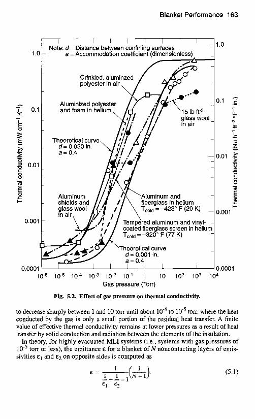
where l is the thickness of the MLI between the hot and cold boundaries. In Fig. 5.3, theoretical and experimental data for embossed aluminized (one sur-
face) Mylar insulation are plotted against number of insulation-blanket layers. As indicated by Eq. (5.1), the emittance for a multilayer blanket theoretically varies (directly) with one over one plus the number of layers. However, in practice, sim- ply increasing the number of layers past a certain value will not improve perfor- mance. As the number of layers increases, radiative heat transfer becomes small compared with conductive "shorts" between layers and other losses. Thus, a point of
0.5
0.1
8 ~5 .005 ID
.001
.0005
l I I I I 6 ", Q,¢OAO installed
"', OAO installed O "',, O y LM installed O
I-~ ~'~JO,~ LM blanket tests I \ O",~,_ Incl supports I \ O ~'-, ,. Vents and seams
o 0 o
I ~ M blanket tests b~arneket O
]-- ~ EMy = 0.40 __ t Thelretical/ ~ _
0 20 40 60 80 100 Number of aluminized Mylar layers
Fig. 5.3. Effective emittance vs. number of single aluminized layers.
Blanket Per formance 165
diminishing returns is reached. Takingall of these factors into account, one finds that about 25 layers usually suffice to obtain a minimum overall conductance value.
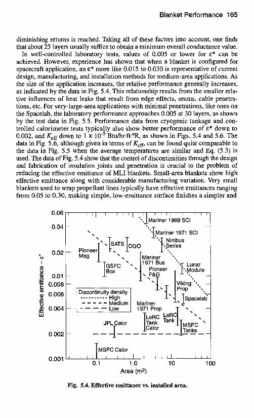
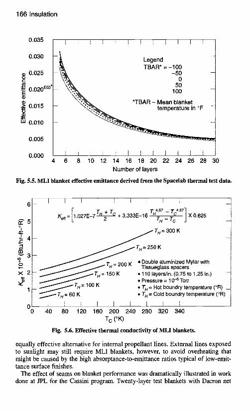
In well-controlled laboratory tests, values of 0.005 or lower for e* can be achieved. However, experience has shown that when a blanket is configured for spacecraft application, an e* more like 0.015 to 0.030 is representative of current design, manufacturing, and installation methods for medium-area applications. As the size of the application increases, the relative performance generally increases, as indicated by the data in Fig. 5.4. This relationship results from the smaller rela- tive influences of heat leaks that result from edge effects, seams, cable penetra- tions, etc. For very-large-area applications with minimal penetrations, like ones on the Spacelab, the laboratory performance approaches 0.005 at 30 layers, as shown by the test data in Fig. 5.5. Performance data from cryogenic tankage and con- trolled calorimeter tests typically also show better performance of e* down to 0.002, and Kef f down to 1 x 10 -5 Btu/hr.ft.°R, as shown in Figs. 5.4 and 5.6. The data in Fig. 5.6, although given in terms of Keff, can be found quite comparable to the data in Fig. 5.5 when the average temperatures are similar and Eq. (5.3) is used. The data of Fig. 5.4 show that the control of discontinuities through the design and fabrication of insulation joints and penetration is crucial to the problem of reducing the effective emittance of MLI blankets. Small-area blankets show high effective emittance along with considerable manufacturing variation. Very small blankets used to wrap propellant lines typically have effective emittances ranging from 0.05 to 0.30, making simple, low-emittance surface finishes a simpler and
0.06
0.04
0.02
(!) to t- in 0.01
• r= 0 . 0 0 8 (1) .~ 0.006
~. 0.004 IJJ
0.002
0.001
L
I ' ' ' 1 ' ' ' i ~ I ~ t ~ ~ I "',J_Mariner1969SCI
" l r
,, ""lMariner 1971 % scI " ,, T.,AT,. T ' --'Q- Nimbus T " r ~1 ° G ° l',Series
Pioneerl ,, _._ / ",, _ Mag / ", , /Mariner "',
- u~''F"L; " " ,, /1971. Bus ",.-,-, Lunar IBox "t , P~(~ eer T l``Module_
" " - T + ivi ,n0",, _1_', Prop ", Discontinuity density "!, / T "--
High. . J- "1,, ISpacelab" Mecnum Mariner ~-
. . . . Low 1971 Prop T ",, - LeRC ,, TLeRC _ .
~C I" C lank I~ a "~ JP alor Tank / MSFC alor nks
. . . . . . . . . . , . - -
]MSIFC Calor , , , , , , 1 L ~ I L l , , , ,
0.1 1.0 10 100 Area (m 2)
Fig. 5.4. Effective emittance vs. installed area.
1 6 6 I n s u l a t i o n
0.035 I I I I t I I I I I I I ......
0.030 Legend
/ ' . ~ \ TBAR = - 1 0 0 o.o25 - 5 0 -
o
= I ":.:','* . o ° • =- o.o2o ~° ' *L " . ' N 1 ;o -
a~ *TBAR - Mean blanket .~ 0.015 " : ' : . ~ ~ temperature in °F -
o 0.010 - '" t~ .... : ' ; " : ~
0.005 - ............................................
0 , 0 0 0 I I 1 I I i I I I ....... I I I . . . . . .
4 6 8 10 12 14 16 18 20 22 24 26 28 30
Number of layers
Fig. 5.5. MLI blanket effective emittance derived from the Spacelab thermal test data.
t r 5 o
e.-
,4--* rn " - ' 3
tO + Q ' t ' -
x 2
1
m
0 0
....... I I I I I t I 1
[, c4.0 l + T~ + 3.333E-16 X 0.625 Eel f = .027E-7 T , 2 "~H - ~CC -J
T H = 300 K
, • • T H = 200 K
. ~ TH= 150K
-~________ ~ TH= 1 0 0 K
~ T H = 6 0 K
...... I 1 I I I I 40 80 120 160 200 240
T c (°K)
T H = 250 K
• Double aluminized Mylar with Tissueglass spacers
• 110 layers/in. (0.75 to 1.25 in.) -- • Pressure = 10 -6 Torr • T H = Hot boundry temperature (°R) _ • T H = Cold boundry temperature (°R)
I I 1 280 320 340
Fig. 5.6. Effective thermal conductivity of MLI blankets.
equally effective alternative for internal propellant lines. External lines exposed to sunlight may still require MLI blankets, however, to avoid overheating that might be caused by the high absorptance-to-emittance ratios typical of low-emit- tance surface finishes.
The effect of seams on blanket performance was dramatically illustrated in work done at JPL for the Cassini program. Twenty-layer test blankets with Dacron net
Blanket Performance 167
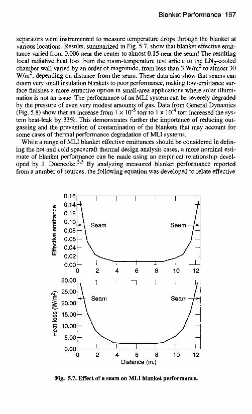
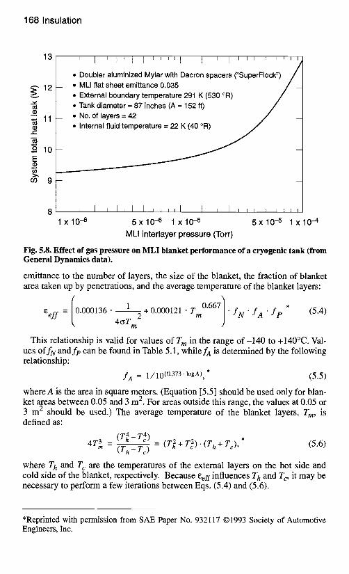
separators were instrumented to measure temperature drops through the blanket at various locations. Results, summarized in Fig. 5.7, show that blanket effective emit- tance varied from 0.006 near the center to almost 0.15 near the seam! The resulting local radiative heat loss from the room-temperature test article to the LN2-cooled chamber wall varied by an order of magnitude, from less than 3 W/m 2 to almost 30 W/m 2, depending on distance from the seam. These data also show that seams can doom very small insulation blankets to poor performance, making low-emittance sur- face finishes a more attractive option in small-area applications where solar illumi- nation is not an issue. The performance of an MLI system can be severely degraded by the pressure of even very modest amounts of gas. Data from General Dynamics (Fig. 5.8) show that an increase from 1 x 10 -5 torr to 1 x 10 -4 torr increased the sys- tem heat-leak by 33%. This demonstrates further the importance of reducing out- gassing and the prevention of contamination of the blankets that may account for some cases of thermal performance degradation of MLI systems.
While a range of MLI blanket effective emittances should be considered in defin- ing the hot and cold spacecraft thermal design analysis cases, a more nominal esti- mate of blanket performance can be made using an empirical relationship devel- oped by J. Doenecke. 5"3 By analyzing measured blanket performance reported from a number of sources, the following equation was developed to relate effective
(D tO t -
.=_ E
.>_ to
I i i
0.16 0.14 0.12 0.10 0.08 0.06 0.04 0.02 0.00
0
I I I
Seam . . t
. . . .
2 4 6 8 10 12
30.00
~-, 25.00 E
20.00
(n 15.00 o
10.00 - (D
-!- 5.00
0.00 0
J I I I I I
I I ........ I I I 2 4 6 8 10 12
Distance (in.)
Fig. 5.7. Effect of a seam on MLI blanket performance.
168 Insu la t i on
13
t l : l
• ~ 11
t " ' i
o 10 E
m 9
I i i t l l i J l l l l I
• Doubler aluminized Mylar with Dacron spacers ("SuperFIock") • MLI flat sheet emittance 0.035
• External boundary temperature 291 K (530 °R) • Tank diameter = 87 inches (A = 152 ft) • No. of layers = 42 • Internal fluid temperature = 22 K (40 °R)
I I
1 x 1 0 - 6
I L I i I I l l l l I i i i i i i i l l
5 x 1 0 -6 l x 1 0 -5 5 x 1 0 -5 l x 1 0 -4
MLI interlayer pressure (Torr)
Fig. 5.8. Effect of gas pressure on MLI blanket performance of a cryogenic tank (from General Dynamics data).
emittance to the number of layers, the size of the blanket, the fraction of blanket area taken up by penetrations, and the average temperature of the blanket layers:
e e f f = (0.000136" 1 0.667 / . (5.4) 4fiT 2 +0"000121 • T m . f N . f A f p *
m
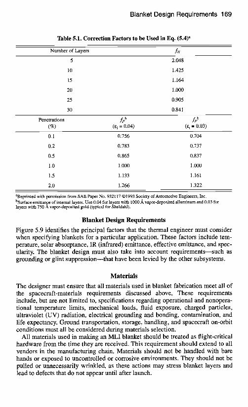
This relationship is valid for values of T m in the range o f -140 to +140°C. Val- ues o f f N and f e can be found in Table 5.1, while fA is determined by the following relationship:
f a = 1/10(0.373 "l°g a), * (5.5)
where A is the area in square meters. (Equation [5.5] should be used only for blan- ket areas between 0.05 and 3 m 2. For areas outside this range, the values at 0.05 or 3 m 2 should be used.) The average temperature of the blanket layers, T m, is defined as:
4T3m (T4- T 4) , = (T h - Tc ) = (T~ + T 2 ) . ( T h + Tc), (5.6)
where T h and T c are the temperatures of the external layers on the hot side and cold side of the blanket, respectively. Because eeff influences T h and T c, it may be necessary to perform a few iterations between Eqs. (5.4) and (5.6).
*Reprinted with permission from SAE Paper No. 932117 01993 Society of Automotive Engineers, Inc.
Blanket Design Requirements 169
Table 5.1. Correction Factors to be Used in Eq. (5.4) a
Number of Layers fN
5 2.048
10 1.425
15 1.164
20 1.000
25 0.905
30 0.841
Penetrations f pb f pb (%) (E i =0.04) (£i =0.03)
0.1 0.756 0.704
0.2 0.783 0.737
0.5 0.865 0.837
1.0 1.000 1.000
1.5 1.133 1.161
2.0 1.266 1.322
aReprinted with permission from SAE Paper No. 932117 ©1993 Society of Automotive Engineers, Inc. bSurface emittance of internal layers. Use 0.04 for layers with 1000/~ vapor-deposited alluminum and 0.03 for layers with 750 A vapor-deposited gold (typical for Sheldahl).
Blanket Design Requirements
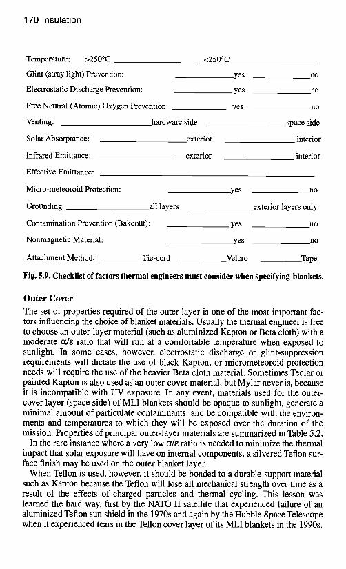
Figure 5.9 identifies the principal factors that the thermal engineer must consider when specifying blankets for a particular application. These factors include tem- perature, solar absorptance, IR (infrared) emittance, effective emittance, and spec- ularity. The blanket design must also take into account requirements--such as grounding or glint suppression--that have been levied by the other subsystems.
Materials
The designer must ensure that all materials used in blanket fabrication meet all of the spacecraft-materials requirements discussed above. These requirements include, but are not limited to, specifications regarding operational and nonopera- tional temperature limits, mechanical loads, fluid exposure, charged particles, ultraviolet (UV) radiation, electrical grounding and bonding, contamination, and life expectancy. Ground transportation, storage, handling, and spacecraft on-orbit conditions must all be considered during materials selection.
All materials used in making an MLI blanket should be treated as flight-critical hardware from the time they are received. This requirement should extend to all vendors in the manufacturing chain. Materials should not be handled with bare hands or exposed to uncontrolled or corrosive environments. They should not be pulled or unnecessarily wrinkled, as these actions may stress blanket layers and lead to defects that do not appear until after launch.
170 Insulation
Temperature: >250°C
Glint (stray light) Prevention:
Electrostatic Discharge Prevention:
Free Neutral (Atomic) Oxygen Prevention:
Venting:
Solar Absorptance:
Infrared Emittance:
Effective Emittance:
hardware side
exterior
exterior
<250°C
yes no
yes no
yes no
space side
interior
interior
Micro-meteoroid Protection:
Grounding: all layers
Contamination Prevention (Bakeout):
Nonmagnetic Material:
Attachment Method: Tie-cord
yes no
exterior layers only
yes no
yes no
Velcro Tape
Fig. 5.9. Checklist of factors thermal engineers must consider when specifying blankets.
Outer Cover
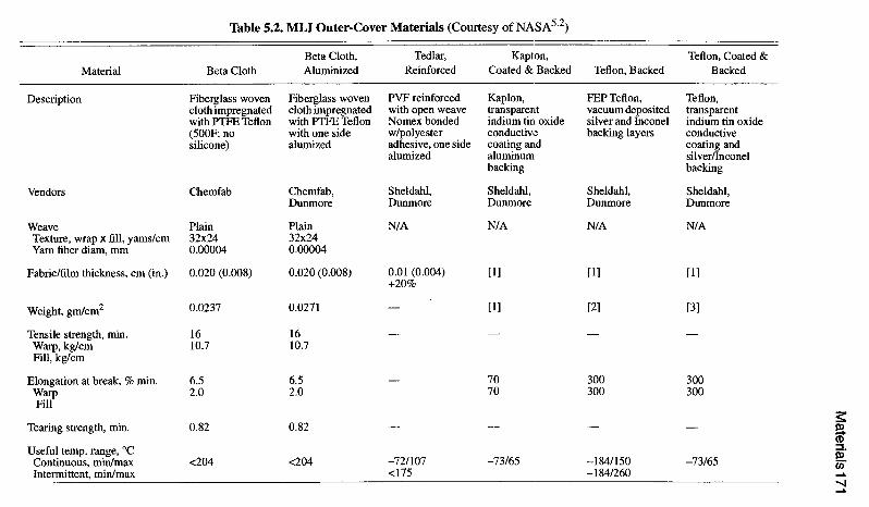
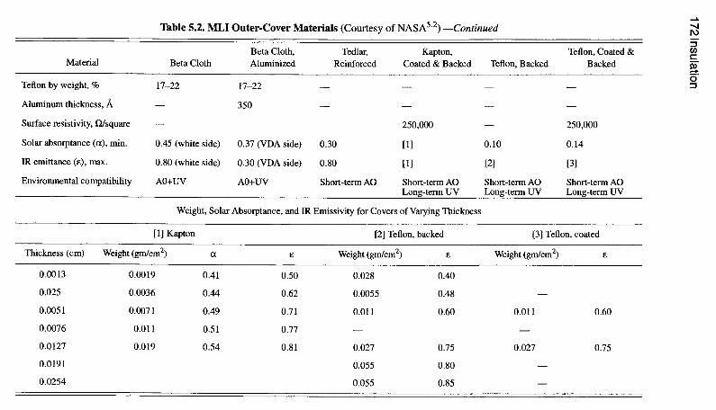
The set of properties required of the outer layer is one of the most important fac- tors influencing the choice of blanket materials. Usually the thermal engineer is free to choose an outer-layer material (such as aluminized Kapton or Beta cloth) with a moderate ode ratio that will run at a comfortable temperature when exposed to sunlight. In some cases, however, electrostatic discharge or glint-suppression requirements will dictate the use of black Kapton, or micrometeoroid-protection needs will require the use of the heavier Beta cloth material. Sometimes Tedlar or painted Kapton is also used as an outer-cover material, but Mylar never is, because it is incompatible with UV exposure. In any event, materials used for the outer- cover layer (space side) of MLI blankets should be opaque to sunlight, generate a minimal amount of particulate contaminants, and be compatible with the environ- ments and temperatures to which they will be exposed over the duration of the mission. Properties of principal outer-layer materials are summarized in Table 5.2.
In the rare instance where a very low ode ratio is needed to minimize the thermal impact that solar exposure will have on internal components, a silvered Teflon sur- face finish may be used on the outer blanket layer.
When Teflon is used, however, it should be bonded to a durable support material such as Kapton because the Teflon will lose all mechanical strength over time as a result of the effects of charged particles and thermal cycling. This lesson was learned the hard way, first by the NATO II satellite that experienced failure of an aluminized Teflon sun shield in the 1970s and again by the Hubble Space Telescope when it experienced tears in the Teflon cover layer of its MLI blankets in the 1990s.
Materials
171
r.~
0 0 0 @
r~ =1 0 H
~ 8 "~ .~
"~0
~
oo
~
=o
~O
t~
oo
~,-a ~'~
~~~~ ~ ~ ~-~ ~~-~
0
~~
~
0 o
-!
~" I
oo
~ o
o 0 O+
0 0 0 0 0 0 0 0 0 0 d ,,..y.
o (D
~§ 0 ~
o.
I I
I I
O0
0 ,-.~ ,-~
~
:)~
d V
x~
t~
0 ,--q ,-'~
~;~ C~1 0
V
t~
o
172 Insulation
I r~
r~
r~
r~
0
#.
°
"i"
I I
~ =
"=
I ~ v
h
r~
~"
I I
= =
" °
0
0 ~t3
I I
o ~
J d
o d
~ ~
I ~
o o
~ ~
o
,~
V3
~ ! ~
~ ~'~
0 0
~ ~
~ 0
0
Materials 173
Interior Layers
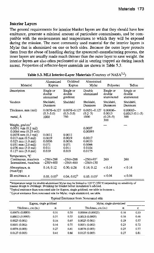
The general requirements for interior blanket layers are that they should have low emittance, generate a minimal amount of particulate contaminants, and be com- patible with the environments and temperatures to which they will be exposed during the mission. The most commonly used material for the interior layers is Mylar that is aluminized on one or both sides. Because the outer layer protects them from the abuse of handling during the spacecraft-manufacturing process, the inner layers are usually made much thinner than the outer layer to save weight, the interior layers are also often perforated to aid in venting trapped air during launch ascent. Properties of reflector-layer materials are shown in Table 5.3.
Table 5.3. MLI Interior-Layer Materials (Courtesy of NASA 5"2)
Aluminized Goldized Aluminized Material Kapton Kapton Mylar Polyester Teflon
Description Single or Single or Double Single or Single or double double aluminized double double aluminized goidized aluminized aluminized
Vendors Sheldahl, Sheldahl Sheldahl, Sheldahl, Sheldahl, Dunmore Dunmore Dunmore Dunmore
Thickness, mm(mil) 0.0076-0.127 0.0076--0.127 0.0051-0.127 0.00006-- 0.00003- (0.3-5.0) (0.3-5.0) (0.2-5) 0.0013 0.0013 (0.1-5)
metal, A 1000 750 1000 (0.25-5) 300 300
Weight, grn/cm 2 0.0051 mm (0.2 mil) 0.0064 mm (0.25 mil) 0.0076 mm (0.3 mil) 0.013 mm (0.5 rail) 0.025 mm (1.0 mil) 0.051 mm (2.0 mil) 0.076 mm (3.0 mil) 0.127 mm (5.0 mil)
Temperature, °(2 Continuous, max/min Intermittent, max/min
Absorptance, ct (max/typ)
IR emittance, e
0.0007 0.00093
0.0011 0.0011 0.0019 0.0019 0.0017 0.0036 0.0036 0.0033 0.071 0.071 0.0066 0.011 0.011 0.0104 0.019 0.019 0.0175
-250/+288 -250/+288 -250/+93 a 260 260 -250/+400 -250/+400 -250/+ 150
0.14; 0.12 0.30; 0.28 0.14; 0.12 < 0.14 < 0.14
0.05; 0.03 b 0.04; 0.02 b 0.05; 0.03 c < 0.04 < 0.04
aTemperature range for double-aluminized Mylar may be limited to 120°C (250°F) depending on sensitivity of blanket design to shrinkage. Shrinking the blanket before installation is advised. bTypical emittance from noncoated side for Kapton, single goldized, see table in footnote c. CTypical emittance from noncoated side for Mylar, single aluminized, see table.
Typical Emittance from Noncoated side
Kapton, single goldized Mylar, single aluminized
Thickness, cm (in.) tx e Thickness, cm (in.) ct e
0.00076 (0.0003) 0.31 0.50 0.00064 (0.00025) 0.16 0.33 0.00013 (0.0005) 0.31 0.55 0.0013 (0.0005) 0.16 0.46 0.0025 (0.001) 0.33 0.65 0.0025 (0.001) 0.19 0.57 0.0051 (0.002) 0.34 0.75 0.0051 (0.002) 0.23 0.72 0.0076 (0.003) 0.27 0.81 0.0076 (0.003) 0.25 0.77 0.0127 (0.005) 0.41 0.86 0.0127 (0.005) 0.27 0.81
174 Insulation
The temperature of the outer-layer material should be calculated for worst-case solar exposure or plume heating conditions to determine if it will impact the inte- rior layers. A high outer-layer temperature may rule out the use of some interior- layer materials that cannot withstand high temperatures, such as aluminized Mylar that melts at 250°C. In such instances, a higher-temperature material, such as alu- minized Kapton, must be used for at least the first several layers. (See page 193 for a description of the high-temperature blankets developed for the Cassini pro- gram.) For most applications in Earth orbit, however, this limitation does not apply.
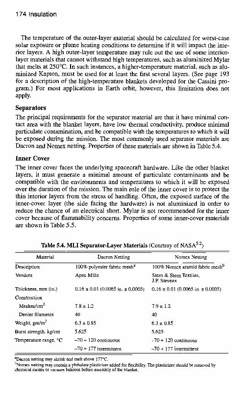
Separators
The principal requirements for the separator material are that it have minimal con- tact area with the blanket layers, have low thermal conductivity, produce minimal particulate contamination, and be compatible with the temperatures to which it will be exposed during the mission. The most commonly used separator materials are Dacron and Nomex netting. Properties of these materials are shown in Table 5.4.
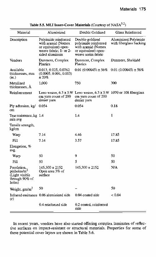
Inner Cover
The inner cover faces the underlying spacecraft hardware. Like the other blanket layers, it must generate a minimal amount of particulate contaminants and be compatible with the environments and temperatures to which it will be exposed over the duration of the mission. The main role of the inner cover is to protect the thin interior layers from the stress of handling. Often, the exposed surface of the inner-cover layer (the side facing the hardware) is not aluminized in order to reduce the chance of an electrical short. Mylar is not recommended for the inner cover because of flammability concerns. Properties of some inner-cover materials are shown in Table 5.5.
Table 5.4. MLI Separator-Layer Materials (Courtesy of NASA 52)
Material Dacron Netting Nomex Netting
Description 100% polyester fabric mesh a
Vendors Apex Mills
Thickness, mm (in.) 0.16 _ 0.01 (0.0065 in. _ 0.0005)
Construction
Meshes/cm 2 7.8 _ 1.2 7.9 _.+ 1.2
Denier filaments 40 40
Weight, gm/m 2 6.3 _ 0.85 6.3 _+ 0.85
Burst strength, kg/cm 5.625 5.625
Temperature range, °C -70 + 120 continuous -70 + 120 continuous
-70 + 177 intermittent -70 + 177 intermittent
100% Nomex aramid fabric mesh b
Stern & Stern Textiles, J.P. Stevens
0.16 _ 0.01 (0.0065 in. _ 0.0005)
aDacron netting may shrink and melt above 177°C. bNomex netting may contain a phthalate plasticizer added for flexibility. The plasticizer should be removed by chemical means or vacuum bakeout before assembly of the blanket.
Materials 175
Table 5.5. MLI Inner-Cover Materials (Courtesy of NASA 5"2)
Material Aluminized Double Goldized Glass Reinforced
Description
Vendors
Available thicknesses, mm (in.)
Metalized thicknesses,
Reinforcement
Polyimide reinforced with aramid (Nomex or equivalent) open- weave fabric; 1- or 2- sided aluminum
Double-goldized polyimide reinforced with aramid (Nomex or equivalent) open- weave scrim fabric
Aluminized Polyimide with fiberglass backing
Dunmore, Complex Dunmore, Complex Dunmore, Sheldahl Plastics Plastics
0.013, 0.025, 0.0762 (0.0005, 0.001, 0.003) _+ 20%
0.01 (0.00045) __. 56% 0.01 (0.00045) _ 56%
1,000 750 300
Ply adhesion, kg/ 0.054 cm
Tear resistance, kg 1.4 1.4 min avg
Tensile strength, kg/cm
Warp 7.14
Fill 7.14
Elongation, % avg.
Warp 50
Fill 50
Porolation, 145,300 _+ 2152 pinholes/m 2 Open area 3% of (Light visible surface through 90% of holes)
Weight, gm/m 2 50
Infrared emittance 0.06 aluminized side (e)
0.4 reinforced side
Leno weave, 6.3 x 5.9/ Leno weave, 6.3 x 5.9/ 1070 or 108 fiberglass cm yam count of 200 cm yarn count of 200 denier yarn denier yarn
0.054 0.18
4.46 17.85
3.57 17.85
9 50
5 50
145,300 _+ 2152 N/A
0.04 coated side
0.2 coated, reinforced side
50
<0.04
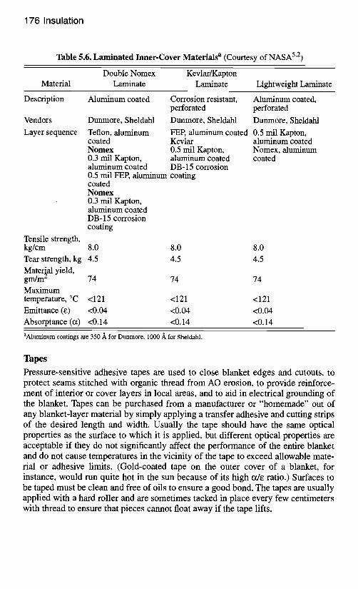
In recent years, vendors have also started offering complex laminates of reflec- tive surfaces on impact-resistant or structural materials. Properties for some of these potential cover layers are shown in Table 5.6.
176 Insulation
Table 5.6. Laminated Inner-Cover Materials a (Courtesy of NASA 5"2)
Double Nomex Kevlar/Kapton Material Laminate Laminate Lightweight Laminate
Description Aluminum coated
Vendors
Layer sequence
Dunmore, Sheldahl
Teflon, aluminum coated Nomex 0.3 mil Kapton, aluminum coated 0.5 rail FEP, aluminum coating coated Nomex 0.3 mil Kapton, aluminum coated DB- 15 corrosion coating
Tensile strength, kg/cm 8.0 Tear strength, kg 4.5 Material yield, grn/m 2 74
Maximum temperature, °C <121 Emittance (e) <0.04 Absorptance (ix) <0.14
Corrosion resistant, Aluminum coated, perforated perforated
Dunmore, Sheldahl Dunmore, Sheldahl
FEP, aluminum coated 0.5 mil Kapton, Kevlar aluminum coated 0.5 mil Kapton, Nomex, aluminum aluminum coated coated DB- 15 corrosion
8.0 8.0 4.5 4.5
74 74
<121 <121 <0.04 <0.04 <0.14 <0.14
aAluminum coatings are 350 A for Dunmore, 1000 A for Sheldahl.
Tapes
Pressure-sensitive adhesive tapes are used to close blanket edges and cutouts, to protect seams stitched with organic thread from AO erosion, to provide reinforce- ment of interior or cover layers in local areas, and to aid in electrical grounding of the blanket. Tapes can be purchased from a manufacturer or "homemade" out of any blanket-layer material by simply applying a transfer adhesive and cutting strips of the desired length and width. Usually the tape should have the same optical properties as the surface to which it is applied, but different optical properties are acceptable if they do not significantly affect the performance of the entire blanket and do not cause temperatures in the vicinity of the tape to exceed allowable mate- rial or adhesive limits. (Gold-coated tape on the outer cover of a blanket, for instance, would run quite hot in the sun because of its high ct/e ratio.) Surfaces to be taped must be clean and free of oils to ensure a good bond. The tapes are usually applied with a hard roller and are sometimes tacked in place every few centimeters with thread to ensure that pieces cannot float away if the tape lifts.
Materials 177
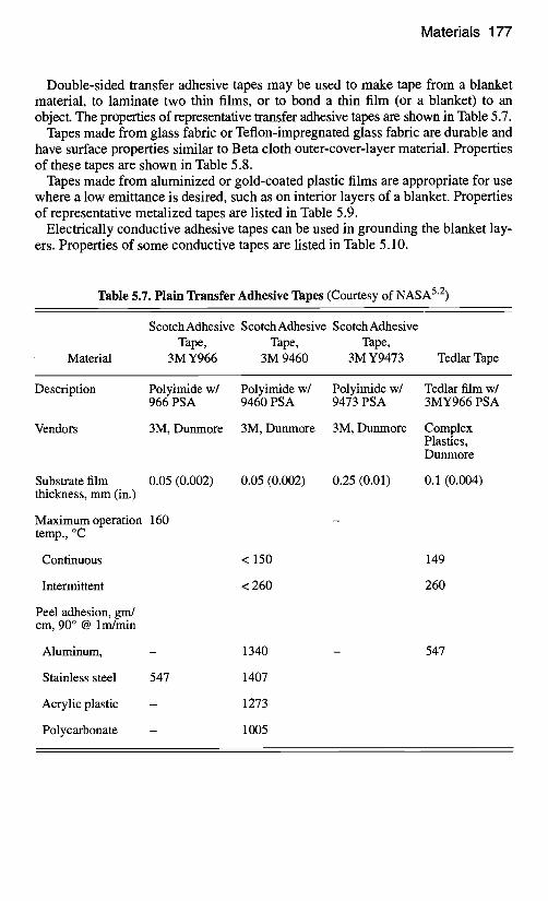
Double-sided transfer adhesive tapes may be used to make tape from a blanket material, to laminate two thin films, or to bond a thin film (or a blanket) to an object. The properties of representative transfer adhesive tapes are shown in Table 5.7.
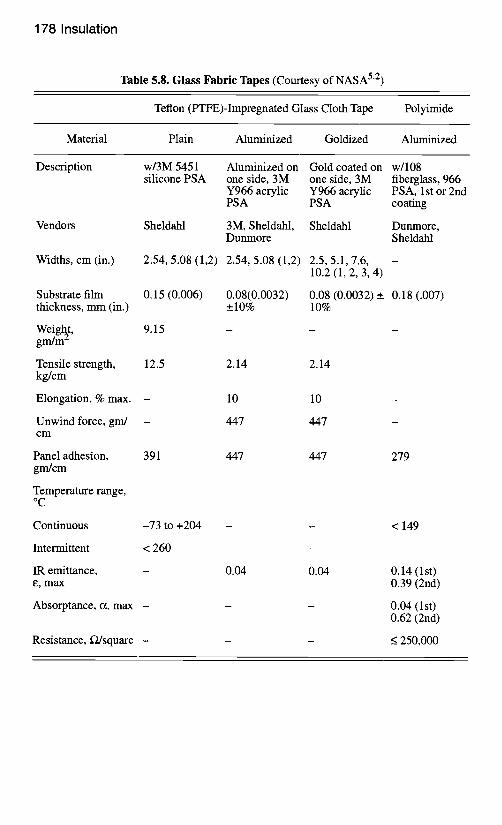
Tapes made from glass fabric or Teflon-impregnated glass fabric are durable and have surface properties similar to Beta cloth outer-cover-layer material. Properties of these tapes are shown in Table 5.8.
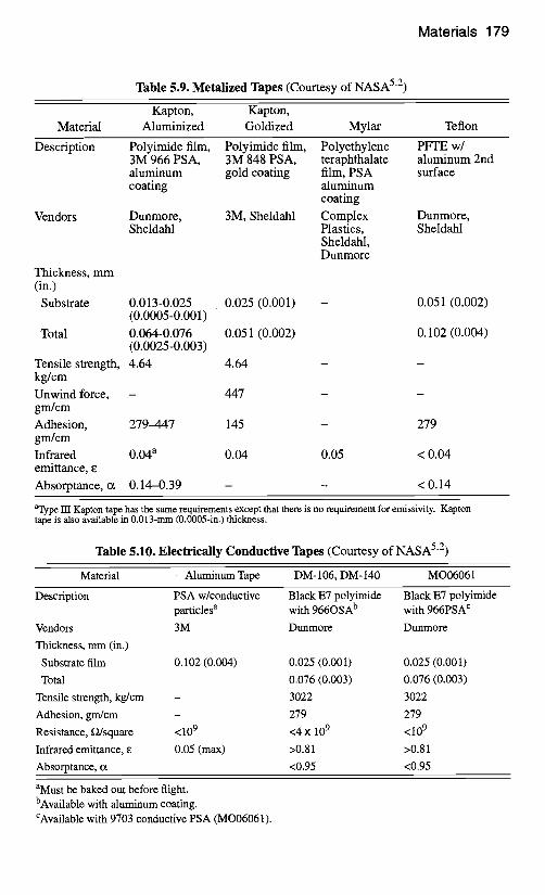
Tapes made from aluminized or gold-coated plastic films are appropriate for use where a low emittance is desired, such as on interior layers of a blanket. Properties of representative metalized tapes are listed in Table 5.9.
Electrically conductive adhesive tapes can be used in grounding the blanket lay- ers. Properties of some conductive tapes are listed in Table 5.10.
Table 5.7. Plain Transfer Adhesive Tapes (Courtesy of NASA 5"2)
Material
ScotchAdhesive ScotchAdhesive ScotchAdhesive Tape, Tape, Tape,
3M Y966 3M 9460 3M Y9473 Tedlar Tape
Description Polyimide w/ Polyimide w/ Polyimide w/ Tedlar film w/ 966 PSA 9460 PSA 9473 PSA 3MY966 PSA
Vendors 3M, Dunmore 3M, Dunmore 3M, Dunmore
Substrate film 0.05 (0.002) 0.05 (0.002) thickness, mm (in.)
Maximum operation 160 temp., °C
Continuous < 150
Intermittent
Peel adhesion, gm/ cm, 90 ° @ lm/min
Aluminum,
Stainless steel 547
Acrylic plastic
Polycarbonate
<260
1340
1407
1273
1005
0.25 (0.01)
Complex Plastics, Dunmore
0.1 (0.004)
149
260
547
178 Insulation
Table 5.8. Glass Fabric Tapes (Courtesy of NASA 5"2)
Teflon (PTFE)-Impregnated Glass Cloth Tape Polyimide
Material Plain Aluminized Goldized Aluminized
Description
Vendors
Widths, cm (in.)
w/3M 5451 silicone PSA
Aluminized on Gold coated on w/108 one side, 3M one side, 3M fiberglass, 966 Y966 acrylic Y966 acrylic PSA, 1st or 2nd PSA PSA coating
Sheldahl 3M, Sheldahl, Sheldahl Dunmore, Dunmore Sheldahl
2.54, 5.08 (1,2) 2.54, 5.08 (1,2) 2.5, 5.1, 7.6, 10 .2 (1 ,2 ,3 ,4 )
Substrate film thickness, mm (in.)
Weight, gm/m 2
Tensile strength, kg/cm
Elongation, % max. -
Unwind force, gm/ - cm
Panel adhesion, grrgcm
Temperature range, o C
Continuous
Intermittent
IR emittance, e, max
Absorptance, ct, max -
0.15 (0.006) 0.08(0.0032) 0.08 (0.0032) _ 0.18 (.007) _+10% 10%
9.15
12.5 2.14 2.14
10 10
447 447
391 447 447 279
-73 to +204 - - < 149
< 260
0.04 0.04 0.14 (1st) 0.39 (2nd)
0.04 (lst) 0.62 (2nd)
Resistance, D/square - - - < 250,000
Materials 179
Table 5.9. Metalized Tapes (Courtesy of NASA 5"2)
Kapton, Kapton, Material Aluminized Goldized Mylar Teflon
Description Polyimide film, 3M 966 PSA, aluminum coating
Vendors Dunmore, Sheldahl
Polyimide film, Polyethylene PFTE w/ 3M 848 PSA, teraphthalate aluminum 2nd gold coating film, PSA surface
aluminum coating
3M, Sheldahl Complex Dunmore, Plastics, Sheldahl Sheldahl, Dunmore
Thickness, mm (in.)
Substrate 0.013-0.025 0.025 (0.001) (0.0005-0.001)
Total 0.064-0.076 0.051 (0.002) (0.0025-0.003)
Tensile strength, 4.64 4.64 kg/cm
Unwind force, - 447 gm/cm
Adhesion, 279-447 145 grn/cm
Infrared 0.04 a 0.04 emittance, e
Absorptance, tx 0.14-0.39
0.051 (0.002)
0.102 (0.004)
279
0.05 < 0.04
<0.14
aType III Kapton tape has the same requirements except that there is no requirement for emissivity. Kapton tape is also available in 0.013-mm (0.0005-in.) thickness.
Table 5.10. Electrically Conductive Tapes (Courtesy of NASA 5"2)
Material Aluminum Tape DM- 106, DM- 140 MO06061
Description PSA w/conductive Black E7 polyimide Black E7 polyimide particles a with 966OSA b with 966PSA c
Vendors 3 M Dunmore Dunmore
Thickness, mm (in.)
Substrate film 0.102 (0.004) 0.025 (0.001) 0.025 (0.001)
Total 0.076 (0.003) 0.076 (0.003)
Tensile strength, kg/cm - 3022 3022
Adhesion, gm/cm - 279 279
Resistance, D/square <109 <4 x 10⁹ <109
Infrared emittance, e 0.05 (max) >0.81 >0.81
Absorptance, o~ <0.95 <0.95
aMust be baked out before flight. bAvailable with aluminum coating. CAvailable with 9703 conductive PSA (MO06061).
180 Insulation
Thread
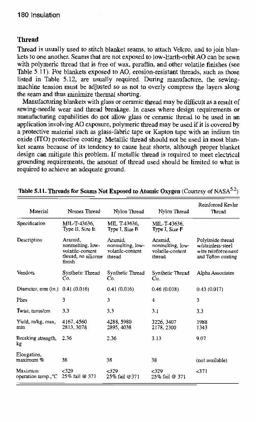
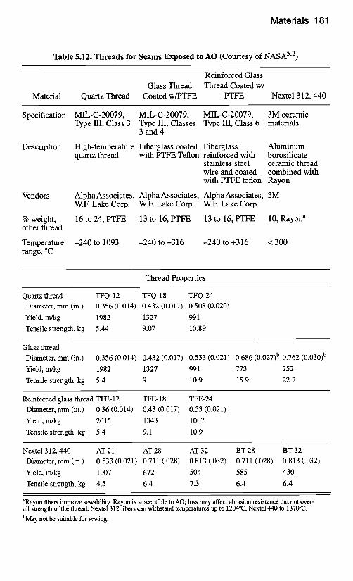
Thread is usually used to stitch blanket seams, to attach Velcro, and to join blan- kets to one another. Seams that are not exposed to low-Earth-orbit AO can be sewn with polymeric thread that is free of wax, paraffin, and other volatile finishes (see Table 5.11). For blankets exposed to AO, erosion-resistant threads, such as those listed in Table 5.12, are usually required. During manufacture, the sewing- machine tension must be adjusted so as not to overly compress the layers along the seam and thus minimize thermal shorting.
Manufacturing blankets with glass or ceramic thread may be difficult as a result of sewing-needle wear and thread breakage. In cases where design requirements or manufacturing capabilities do not allow glass or ceramic thread to be used in an application involving AO exposure, polymeric thread may be used if it is covered by a protective material such as glass-fabric tape or Kapton tape with an indium tin oxide (ITO) protective coating. Metallic thread should not be used in most blan- ket seams because of its tendency to cause heat shorts, although proper blanket design can mitigate this problem. If metallic thread is required to meet electrical grounding requirements, the amount of thread used should be limited to what is required to achieve an adequate ground.
Table 5.11. Threads for Seams Not Exposed to Atomic Oxygen (Courtesy of NASA 5"2)
Reinforced Kevlar Material Nomex Thread Nylon Thread Nylon Thread Thread
Specification MIL-T-43636, MIL-T-43636, MIL-T-43636, Type II, Size E Type I, Size E Type I, Size F
Description Aramid, Aramid, Aramid, Polyimide thread nonmelting, low- nonmelting, low- nonmelting, low- w/stainless-steel volatile-content volatile-content volatile-content wire reinforcement thread, no silicone thread thread and Teflon coating finish
Vendors Synthetic Thread Synthetic Thread Synthetic Thread Alpha Associates Co. Co. Co.
Diameter, mm (in.) 0.41 (0.016)
Plies 3
0.41 (0.016)
3
Twist, turns/cm 3.3
Yield, m/kg, max, 4167, 4560 min 2813, 3078
Breaking strength, 2.36 kg
Elongation, maximum % 38
3.3
4288, 5980 2895, 4038
2.36
38
Maximum <329 operation temp.,°C 25% fail @ 371
<329 25% fail @371
0.46 (0.018) 0.43 (0.017)
4 3
3.1 3.3
3226, 3407 1988 2178, 2300 1343
3.13 9.07
38
<329 25% fail @ 371
(not available)
<371
Materials 181
Table 5.12. Threads for Seams Exposed to AO (Courtesy of NASA 5"2)
Material
Reinforced Glass Glass Thread Thread Coated w/
Quartz Thread Coated w/PTFE PTFE Nextel 312, 440
Specification
Description
Vendors
% weight, other thread
Temperature range, °C
MIL-C-20079, MIL-C-20079, MIL-C-20079, Type III, Class 3 Type III, Classes Type III, Class 6
3 and 4
High-temperature Fiberglass coated Fiberglass quartz thread with PTFE Teflon reinforced with
stainless steel wire and coated
3M ceramic materials
Aluminum borosilicate ceramic thread combined with
with PTFE teflon Rayon
Alpha Associates, Alpha Associates, Alpha Associates, 3M W.E Lake Corp. W.E Lake Corp. W.F. Lake Corp.
16 to 24, PTFE 13 to 16, PTFE 13 to 16, PTFE 10, Rayon a
-240 to 1093 -240 to +316 -240 to +316 < 300
Thread Properties
Quartz thread Diameter, mm (in.)
Yield, m/kg
Tensile strength, kg
TFQ-12 TFQ-18 TFQ-24 0.356 (0.014) 0.432 (0.017) 0.508 (0.020)
1982 1327 991
5.44 9.07 10.89
Glass thread Diameter, mm (in.)
Yield, m/kg
Tensile strength, kg
0.356 (0.014) 0.432 (0.017) 0.533 (0.021) 0.686 (0.027) b 0.762 (0.030) b
1982 1327 991 773 252
5.4 9 10.9 15.9 22.7
Reinforced glass thread TFE- 12 TFE- 18 TFE-24 Diameter, mm (in.) 0.36 (0.014) 0.43 (0.017) 0.53 (0.021)
Yield, m/kg 2015 1343 1007
Tensile strength, kg 5.4 9.1 10.9
Nextel 312, 440 AT-21 AT-28 AT-32 BT-28 BT-32 Diameter, mm (in.) 0.533 (0.021) 0.711 (.028) 0.813 (.032) 0.711 (.028) 0.813 (.032)
Yield, m/kg 1007 672 504 585 430
Tensile strength, kg 4.5 6.4 7.3 6.4 6.4
aRayon fibers improve sewability. Rayon is susceptible to AO; loss may affect abrasion resistance but not over- all strength of the thread. Nexte1312 fibers can withstand temperatures up to 1204°(2, Nexte1440 to 1370°(2. bMay not be suitable for sewing.
182 Insulation
Adhesives
Low-outgassing, silicone-based adhesives are commonly used to bond fasteners to structure in low-to-moderate-temperature applications. These silicone adhesives should not be used on surfaces directly exposed to the low Earth-orbit environment or on surfaces expected to reach temperatures of 200°C or more. The bond should be allowed to set for at least 24 hours. Heating up to 65°C may be used to improve adhesion.
Provisions for Venting
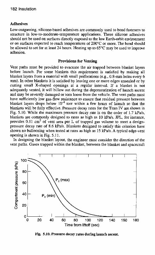
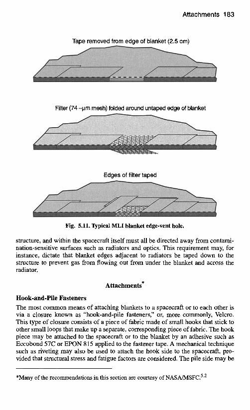
Vent paths must be provided to evacuate the air trapped between blanket layers before launch. For some blankets this requirement is satisfied by making all blanket layers from a material with small perforations (e.g., 0.8-mm holes every 6 mm). In other blankets it is satisfied by leaving one or more edges unsealed or by cutting small X-shaped openings at a regular interval. If a blanket is not adequately vented, it will billow out during the depressurization of launch ascent and may be severely damaged or torn loose from the vehicle. The vent paths must have sufficiently low gas-flow resistance to ensure that residual pressure between blanket layers drops below 10 -4 torr within a few hours of launch so that the blankets will be fully effective. Pressure decay rates for the Titan IV are shown in Fig. 5.10. While the maximum pressure decay rate is on the order of 1.7 kPa/s, blankets are commonly designed to rates as high as 10 kPa/s. JPL, for instance, provides 0.11 cm 2 of vent area per L of trapped gas volume to meet a design- pressure decay rate of 8.6 kPa/s. Blankets designed to satisfy this criterion have shown no ballooning when tested at rates as high as 15 kPa/s. A typical edge-vent opening is shown in Fig. 5.11.
In designing the blanket layout, the engineer must consider the direction of the vent paths. Gases trapped within the blanket, between the blanket and spacecraft
100 f t .
80 ! _ _
ffl
60
E 40
E o 20
0 0
] I I I I I I 1
ax)
J I , I 20 40 60 80 100 120 140
Time from liftoff ( s e c )
I 160
I
180
Fig. 5.10. Pressure decay rates during launch ascent.
Attachments 183
Tape removed from edge of blanket (2.5 cm)
........
Filter (74 -l.tm mesh) folded around untaped edge of blanket
Edges of filter taped
ii ! J ~ ~4~f~ .~I~iii~i~i~/~J ~ ~
Fig. 5.11. Typical MLI blanket edge-vent hole.
structure, and within the spacecraft itself must all be directed away from contami- nation-sensitive surfaces such as radiators and optics. This requirement may, for instance, dictate that blanket edges adjacent to radiators be taped down to the structure to prevent gas from flowing out from under the blanket and across the radiator.
Attachments*
Hook-and-Pile Fasteners
The most common means of attaching blankets to a spacecraft or to each other is via a closure known as "hook-and-pile fasteners," or, more commonly, Velcro. This type of closure consists of a piece of fabric made of small hooks that stick to other small loops that make up a separate, corresponding piece of fabric. The hook piece may be attached to the spacecraft or to the blanket by an adhesive such as Eccobond 57C or EPON 815 applied to the fastener tape. A mechanical technique such as riveting may also be used to attach the hook side to the spacecraft, pro- vided that structural stress and fatigue factors are considered. The pile side may be
*Many of the recommendations in this section are courtesy of NASA/MSFC. 5"2
184 Insulation
sewn to the blanket or attached by ultrasonic welding using an appropriate adhe- sive. Welds or stitching may pass through the entire blanket to provide a more durable attachment or to prevent inner-layer shifting, but they will degrade the performance of the blanket in a small local area. Space-shuttle flammability requirements limit the size of each hook-and-pile fastener to 77 cm 2 and require adjacent fasteners to be separated by at least 5 cm. Hook-and-pile fasteners make blanket installation and removal quick and easy, although they are not acceptable on some programs because they generate some particulate contaminants during blanket removal.
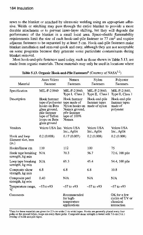
Most hook-and-pile fasteners used today, such as those shown in Table 5.13, are made from organic materials. These materials may only be used in locations where
Table 5.13. Organic Hook-and-Pile Fasteners a (Courtesy of NASA 52)
Astro Velcro Nomex Nylon Polyester Material Fastener Fasteners Fasteners Fasteners
Specification MIL-F-21840
Description
Vendors
Hook and loop filament size, mm (in.)
Hooks/linear cm
Hook fastener Hook fastener Hook-and-pile tape of polyester tape made of fastener tapes hooks on Beta Nylon hooks on made of nylon glass ground, Nomex ground, pile fastener pile fastener tape of Teflon tape of 100% loops on Beta Nomex glass ground
Velcro USA Inc. Velcro USA Velcro USA Inc., Aplix Inc., Aplix
0.2 (0.008) 0.17 (0.007) 0.2 (0.008)
MIL-F-21840, MIL-F-21840, MIL-F-21840, Type I, Class 2 Type II, Class 1 Type II, Class 1
Hook-and-pile fastener tapes made of polyester
Velcro USA Inc., Aplix
0.2 (0.008)
110 112 100 75
Hook tape breaking N/A strength, kg min
Loop tape breaking N/A strength, kg min
Composite shear 6.8 strength, kg min
Composite peel 0.40 strength, kg min
Temperature range, -57to+93 o C
70.3 56.7 72.6, 100 pile
65.3 45.4 54.4, 100 pile
6.8 6.8 10.8
N/A N/A N/A
-57 to +93 -57 to +93 -57 to +93
Comments Recommended OK for a few for high- cycles of UV or temperature chemical applications interaction
aData for these materials are given for 2.5-cm-wide (1-in-wide) tapes. Hooks are generally placed every four picks on the ground fabric, loops are every three picks. Composite shear strength is tested with 7.6 cm (3 in.) overlap of hook-and-pile tapes.
Attachments 185
they will not be directly exposed to AO for more than a few hours. When using these fasteners in a low-Earth-orbit environment, NASA/MSFC recommended allowing 6 to 12 mm overhang by the blanket to shield the fastener from either direct or scattered AO. (In some cases, flaps as large as 5 cm have been used.) Hook-and-pile fasteners are generally available in 2.5-cm widths, but they can sometimes be found in widths of 1.6, 1.9, 3.8, and 5 cm. To prevent unraveling, NASA/MSFC also recommended that one n o t slit the fastener tapes lengthwise or trim selvage edges. Fastener tapes may be slit widthwise for forming an arc or adjustment around a protrusion.
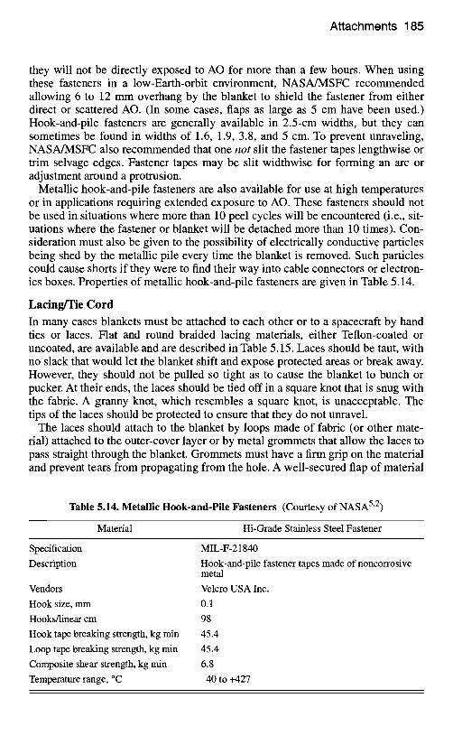
Metallic hook-and-pile fasteners are also available for use at high temperatures or in applications requiting extended exposure to AO. These fasteners should not be used in situations where more than 10 peel cycles will be encountered (i.e., sit- uations where the fastener or blanket will be detached more than 10 times). Con- sideration must also be given to the possibility of electrically conductive particles being shed by the metallic pile every time the blanket is removed. Such particles could cause shorts if they were to find their way into cable connectors or electron- ics boxes. Properties of metallic hook-and-pile fasteners are given in Table 5.14.
Lacing~ie Cord In many cases blankets must be attached to each other or to a spacecraft by hand ties or laces. Flat and round braided lacing materials, either Teflon-coated or uncoated, are available and are described in Table 5.15. Laces should be taut, with no slack that would let the blanket shift and expose protected areas or break away. However, they should not be pulled so tight as to cause the blanket to bunch or pucker. At their ends, the laces should be tied off in a square knot that is snug with the fabric. A granny knot, which resembles a square knot, is unacceptable. The tips of the laces should be protected to ensure that they do not unravel.
The laces should attach to the blanket by loops made of fabric (or other mate- rial) attached to the outer-cover layer or by metal grommets that allow the laces to pass straight through the blanket. Grommets must have a firm grip on the material and prevent tears from propagating from the hole. A well-secured flap of material
Table 5.14. Metallic Hook-and-Pile Fasteners (Courtesy of NASA 5"2)
Material Hi-Grade Stainless Steel Fastener
Specification MIL-F-21840
Description Hook-and-pile fastener tapes made of noncorrosive metal
Vendors Velcro USA Inc. Hook size, mm 0.1
Hooks/linear cm 98 Hook tape breaking strength, kg min 45.4
Loop tape breaking strength, kg min 45.4 Composite shear strength, kg min 6.8
Temperature range, °C -40 to +427
186 Insulation
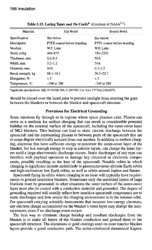
Table 5.15. Lacing Tapes and Tie Cords a (Courtesy of NASA 5"2)
Material Flat Braid Round Braid
Specification See below See below Description PTFE coated before braiding PTFE coated before braiding Vendors W.E Lake W.E Lake Yield, m/kg 446-872 730-2332 Thickness, mm 0.2-0.5 N/A Width, mm 3.2-1.2 N/A Diameter, mm N/A 0.7-1.2 Break strength, kg 68.1-18.1 36.3-22.7 Elongation, % < 5 < 5 Temperature, °C -240 to 288 -240 to 288
aApplicable specifications: MIL-T-43435B; MIL-C-20079H; U.S. Navy 17773A 1118A007X
should be placed over the laced joint to prevent sunlight from entering the gaps between the blankets or between the blanket and spacecraft structure.
Provisions for Electrical Grounding
Some missions fly through or in regions where space plasmas exist. Plasma can serve as a medium for surface charging that can result in considerable potential buildup on the external surface of the spacecraft, including the outer-cover layer of MLI blankets. This buildup can lead to static electric discharge between the spacecraft and the surrounding plasma or between parts of the spacecraft that are to some degree electrically isolated from one another. In addition to surface charg- ing, electrons that have sufficient energy to penetrate the outer-cover layer of the blanket, but low enough energy to stop in interior layers, can charge the inner lay- ers until a large electrostatic discharge occurs. Static discharges of any type can interfere with payload operation or damage key electrical or electronic compo- nents, possibly resulting in the loss of the spacecraft. Notable orbits in which charging is significant include midaltitude to geosynchronous-altitude Earth orbits and high-inclination low Earth orbits, as well as orbits around Jupiter and Saturn.
Spacecraft flying in orbits where charging is an issue will typically have require- ments to ground insulation blankets. Sometimes only the metalized layers of large blankets must be grounded; in other situations the outer surface of the outer-cover layer must also be coated with a conductive material and grounded. The degree of grounding required will usually reflect how sensitive spacecraft components are to static discharges and how severe the charging environment is in the mission orbit. For spacecraft carrying scientific instruments that measure low-energy electrons, any electron charge accumulated on the blanket's outer layer may disrupt the mea- surements, even if no discharge event occurs.
The best way to eliminate charge buildup and resultant discharges from the blanket is to make all layers of the blanket conductive and ground them to the spacecraft structure. The aluminum or gold coatings used on most interior blanket layers provide a good conductive path. The scrim-reinforced aluminized Kapton
Fabrication 187
that is sometimes used as an outer cover, however, can present grounding chal- lenges because the scrim layer has to be removed in a small area to expose the conductive aluminum sandwiched between the Kapton and scrim. The easiest way to get conductive outer-cover layers is to use carbon-loaded (black) Kapton, which is a conductive enough material even without special coatings. One possible prob- lem with black Kapton, however, is that it has an absorptance-to-emittance ratio that is higher than the ratio of traditional (gold-colored) aluminized Kapton, and it will therefore run hotter in sunlight. For many missions, the thermal design can accommodate the higher outer-layer temperature, although achieving this capabil- ity may require additional effort by the thermal engineer. For other missions, ther- mal requirements demand the lower temperatures achievable with gold Kapton or even Teflon outer layers. ITO-coated (sputtered, rather than vapor-deposited) alu- minized Kapton and Teflon may be used in these situations. The ITO serves as a transparent, electrically conductive layer that may be grounded to the spacecraft structure. An important point, however, is that the ITO is fragile and may be degraded with even minimal handling. Wiping for cleaning purposes can ruin the surface, as can bending during manufacture or storage. Thermal bakeout of the blankets may also contribute to the loss of ITO surface conductivity. Because of the difficulty of grounding Teflon, it has largely disappeared as a thermal-control material on satellites in geosynchronous orbits.
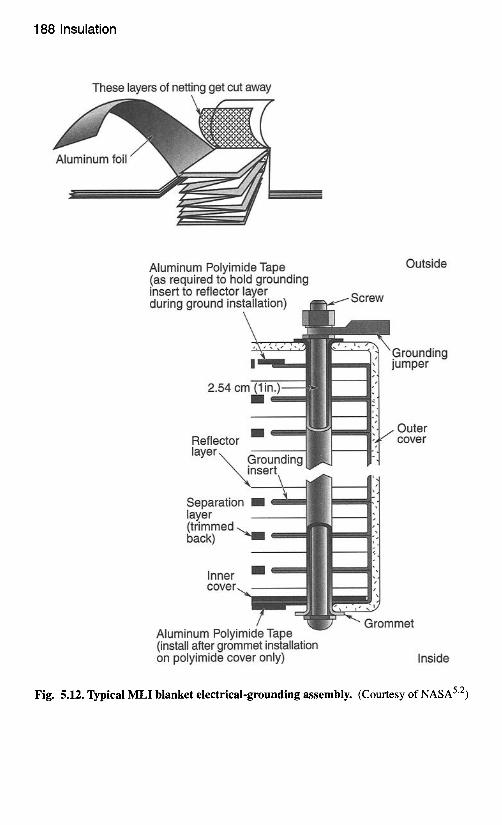
The conductive blanket layers are usually connected at discrete points and grounded to the spacecraft structure. A typical grounding assembly consists of a conductive metal strip interleaved between the blanket layers and secured by a small bolt, as shown in Fig. 5.12. This assembly is made by cutting away a small square of the separator layers and applying a grounding tape (such as aluminum tape with conductive adhesive) accordion-style between adjacent blanket layers, as shown in the figure. A hole is then punched through all layers for the bolt. The bolt passes through a flat washer, an eyelet terminal, the blanket, another flat washer, a lock washer, and a lock nut. Brass and corrosion-resistant steel (CRES) are the preferred materials for bolts, eyelets, and washers. A wire of the required length, such as 22-gauge Teflon-insulated wire, is crimped to the eyelet terminal. The electrical resistance of the assembly should be less than 1 f~.
The number of grounding assemblies required depends on blanket size, the mis- sion charging environment, and the spacecraft sensitivity to discharge. On some programs, blankets with an area less than one square meter are exempt from grounding requirements, while on others all blankets must be grounded. Blankets with areas greater than one square meter are almost always required to have at least two ground straps and often two ground straps per square meter.
Fabrication
Fabrication starts after the thermal engineer has defined the spacecraft or compo- nent blanket requirements and continues until delivery or installation of the blan- kets on the flight item. By the start of this phase, the cognizant hardware, thermal, and blanket engineers should have begun a dialogue in which blanketing require- ments are discussed. These requirements include surface properties, grounding, micrometeoroid protection, and contamination, as outlined in Table 5.1. The method of attaching and supporting the blankets, including any blanket standoffs
188 Insulation
These layers of netting get cut away
Aluminum Polyimide Tape (as required to hold grounding insert to reflector layer during ground ins
2.54 cr
Reflector layer ~ .......
Sep laye (trin bacl
Outside
o ^,,SW
~Grounding jumper
Outer f cover
Aluminum P'otytmlae tape (install after grommet installation on polyimide cover only)
3mmet
Inside
Fig. 5.12. Typical MLI blanket electrical-grounding assembly. (Courtesy of NASA 52)
Fabrication 189
required for micrometeoroid protection, should be understood by this point, since these items drive the size of the blanket pattern.
Several vendors provide blanket patterning and fabrication services, including Swales Aerospace of Beltsville, Maryland, and Space Systems Loral of Palo Alto, California. Use of such support contractors may be an effective way to deal with large patterning tasks when the schedule lacks sufficient time for patterning.
The Work Area
Fabrication should take place in a workshop area that qualifies as a Class 100,000 clean room. Temperature and humidity should be controlled and a positive pres- sure maintained in the room to preserve the cleanliness and optical properties of the MLI material being used or stored in the shop. Temperature and humidity should be monitored 24 hours a day.
The fabrication area should have layout/sewing tables large enough to support the largest blankets being fabricated, sewing machines, a storage area for the rolls of film from which the blankets are fabricated, and cabinets to house tapes, thread, layout tools, punches, patterns, etc.
All tools, equipment, templates, holding fixtures, and other structures that may contact the blankets should be cleaned before use with a solvent having a nonvola- tile residue not exceeding 0.02 g/L. Solvents must be compatible with the compo- nent materials so that the materials are not damaged by normal cleaning opera- tions. Workshop tables should be protected with clean covers when they are not in use. Blankets and materials should be handled with clean white gloves or powder- free latex gloves suitable for clean-room use. Workers should wear clean labora- tory smocks and practice good housekeeping in the work area. Any workers who may be above the blanket assembly area should wear foot coverings.
The Spacecraft Model
Because blankets are custom-tailored to each piece of hardware, access to a geo- metrical representation of the components to be insulated is required to aid in blanket development. The completed flight hardware itself would be ideal, but schedule often makes this impractical. Therefore, a model of the spacecraft or component to be insulated is usually required to aid in sizing and fitting the blan- ket. While this model should contain representations of all the items that the blan- kets must enclose, details like cables, purge lines, propellant/pressurant lines, and micrometeoroid standoffs for the blanket are sometimes missing.
Unfortunately, models that everyone swears are flyable often turn out to be any- thing but. Sometimes, blankets made on such models must be changed to fit the flight hardware even as the latter is en route to final spacecraft-level testing! Depending on the magnitude of these changes, completely new blankets may have to be fabricated, and that additional labor increases costs and affects schedule. Therefore, the blanket engineer should resist beginning the blanket-fabrication process unless the model is of sufficient fidelity to represent the final hardware design. Making sure all parties understand the potential costs and schedule impacts of not having a complete model before proceeding is the responsibility of the blanket engineer. How well the model represents flight hardware is the respon- sibility of the hardware engineer and, to a limited degree, the thermal engineer.
190 Insulation
Patterning Like the manufacture of clothing, blanket fabrication involves the use of pattems. Patterning is the biggest challenge in the blanket-development process. Any method that produces a pattern that fits the hardware is a good one and probably a variation of the right one. Sometimes a detailed pattern can be developed from the full-scale drawing of the hardware to be insulated. At other times the geometry is so complex that the pattern evolves from many pieces of paper taped together on the model (a process some refer to as "throwing paper at the hardware"). Varia- tions between these extremes exist, but development of a pattem always tends to contain a little of each approach.
A pattern starts simple and grows in complexity as cutouts, interfaces to other blankets, hardware attachments, and additional details are incorporated. Eventu- ally, the final pattern evolves and is placed on the hardware for comments from the thermal and hardware-cognizant engineers. This is the time to address open issues. Identify where the blanket ground location should be. Ensure that laced edges will not be in the sun. Consider issues related to blanket installation. Con- cave surfaces (comers, blanket-to-blanket intersections, etc.) that may be illumi- nated should also be avoided. Determine whether the blanket must be readily removable to reach the hardware for activities such as calibration checks, propel- lant loading, or pyro arming. Eliminate line-of-sight paths to apertures and opti- cally sensitive surfaces relative to primary vent paths. Are micrometeoroid requirements being met? Is all hardware present? These are the types of questions and concerns that need to be addressed before proceeding to the detailing of the final pattern. No question is too "dumb."
The final pattern contains all the information needed to fabricate the blanket. Patterns are like engineering drawings; they may contain a title, part number, material list, centerlines, hidden lines, fold lines, fabrication notes, and other information. Flight patterns should be retained in the thermal blanket shop for up to one year following launch. Before destroying a pattern, check with the project to make sure another flight of the same spacecraft or instrument configuration will not be made. Hardware usually changes for a reflight, but the original flight pat- tern can serve as a good preliminary pattern for a subsequent flight. Do not dis- pose of any patterns until determining that no future use for them has been planned.
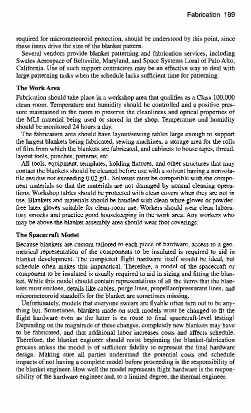
Construction Details In most cases, blanket edges are bound with 1.5-to-2-cm tape and stitched, as shown in Fig. 5.13. The standard tapes are either glass (white), carbon-filled (black) Kapton, or aluminized Kapton, but tapes can be made from any outer-layer material by applying a double-sided transfer adhesive to cut strips of the material. If electrically conductive binding tape like black Kapton is used, the binding should be grounded to the conductive exterior layers by turning under a small (1- cm) tab of the binding every 15 to 30 cm before stitching the edge, as in Fig. 5.13. This is not done for the glass or ITO-coated tapes, because the glass tape is non- conductive and ITO cracks along the tab edge, breaking the conductive path.
Stitching the blanket edge prevents interior layers from shifting during the launch vibration environment and makes the blanket more durable. Some manufacturers
Fabrication 191
AI Grounding tape
[
~ Binding tape
A
15 to 30 cm
Stitch
Grounding / , , / t a b _
j iiiiiNi!iii '" I " ~ k
A - A ~ Stitch
Fig. 5.13. Typical MLI blanket edge finish.
stitch around the entire periphery, while others limit the amount of stitching to improve blanket performance. NASA/MSFC 5"2 recommended stitch length is 3 to 6 mm. Use a 13-mm backstitch to secure each seam at the end. If the thread breaks or runs out in the middle of a stitch line, back up about 25 mm and restart the stitch in a previously made needle hole to reduce blanket perforations. Buttons on each side of the blanket, loosely held together with thread or cord, are also some- times used toward the center of larger blankets to prevent billowing.
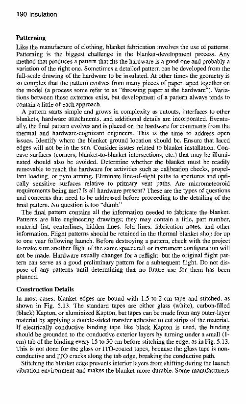
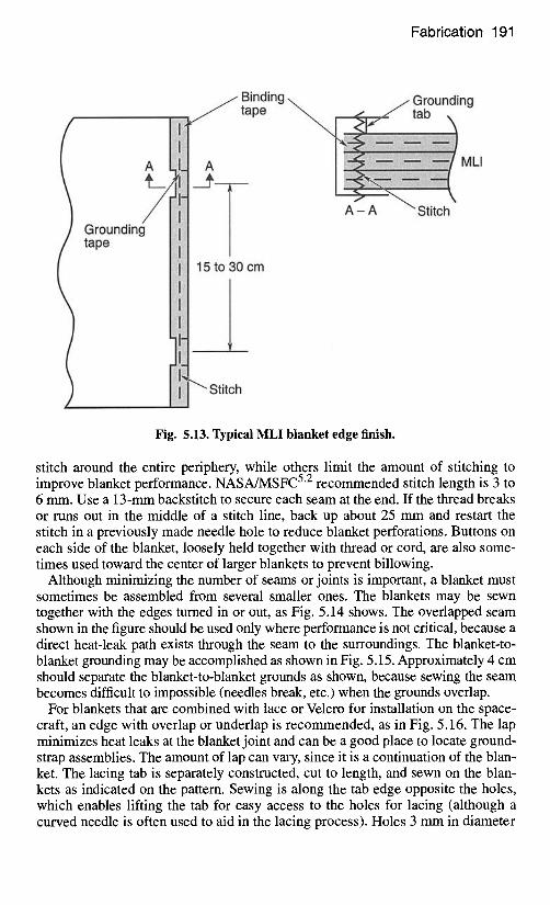
Although minimizing the number of seams or joints is important, a blanket must sometimes be assembled from several smaller ones. The blankets may be sewn together with the edges turned in or out, as Fig. 5.14 shows. The overlapped seam shown in the figure should be used only where performance is not critical, because a direct heat-leak path exists through the seam to the surroundings. The blanket-to- blanket grounding may be accomplished as shown in Fig. 5.15. Approximately 4 cm should separate the blanket-to-blanket grounds as shown, because sewing the seam becomes difficult to impossible (needles break, etc.) when the grounds overlap.
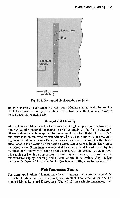
For blankets that are combined with lace or Velcro for installation on the space- craft, an edge with overlap or underlap is recommended, as in Fig. 5.16. The lap minimizes heat leaks at the blanket joint and can be a good place to locate ground- strap assemblies. The amount of lap can vary, since it is a continuation of the blan- ket. The lacing tab is separately constructed, cut to length, and sewn on the blan- kets as indicated on the pattern. Sewing is along the tab edge opposite the holes, which enables lifting the tab for easy access to the holes for lacing (although a curved needle is often used to aid in the lacing process). Holes 3 mm in diameter
192 Insulation
Binding t a p e ~ t ~ ~ S t i t c h
~ /Blanket
Butted and outward
!illii!iiiii!liiiilliiiiiiiiiiiii liiiiiiiiiiilii i i ~ £ i i i i i iiiiiii ii i i !
Overlap seam
liiiliiiiii!iiiliiiiiii ii Iii I i ii ii ii iii iii i i i iii i i
Butted and inward Fig. 5.14. Blanket-to-blanket seam arrangements.
iiiiiiil ~
iiiii !!!iii ............ iilii iiiiiiiI
!i!i!i!i!i!ii
iilill~ iiiii~ iiiiii iili
!iiiiiiii ~iiiiililiiiili iililt ............ I iilili Iii!Ii ii iii~iii~ !lii
!!!ii !!!!!i !i¢i'i! iii! iiiiiiiiiii iii!lilt i!i!i
............ iili
!!!ii !i~iiiii
4 cm
Fig. 5.15. Blanket-to-blanket electrical grounding.
Bakeout and Cleaning 193
c m -1 (underlap)
Fig. 5.16. Overlapped blanket-to-blanket joint.
are then punched approximately 3 cm apart. Matching holes in the interfacing blanket are punched during installation of the blankets on the hardware to match those already in the lacing tab.
Bakeout and Cleaning
All blankets should be baked out in a vacuum at high temperature to allow mois- ture and volatile materials to outgas prior to assembly on the flight spacecraft. Blankets should also be inspected for contamination before flight. Observed con- taminants may be removed by drip-wiping with a clean-room wipe and vacuum- ing, as required. When using Beta cloth as a cover layer, vacuum it with a brush attachment in the direction of the fabric's warp. (Cloth warp is in the direction of the raised fibers. Sometimes it is indicated by an alignment thread placed by the manufacturer; otherwise it can be seen using a ×30 microscope.) A clean-room wipe moistened with an appropriate solvent may also be used to clean blankets, but excessive wiping, cleaning, and solvent use should be avoided. Any blankets permanently degraded by contamination (such as oil spills) must be replaced. 5"2
High-Temperature Blankets
For some applications, blankets may have to endure temperatures beyond the allowable limits of materials commonly used in blanket construction, such as alu- minized Mylar films and Dacron nets (Table 5.16). In such circumstances, other
194 Insulation
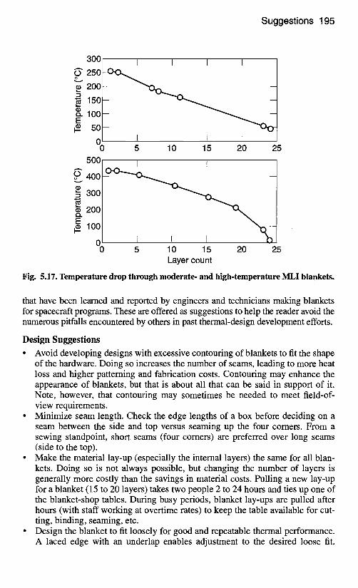
materials must be considered. This was the case in the Cassini program, where insulation blankets would be exposed to solar irradiances 2.7 times greater than that encountered in Earth orbit, plus the heating effects of engine plumes and radi- ation from radioisotope thermoelectric generators. To enable spacecraft to survive these environments, JPL developed two blanket lay-ups, one good to an outer- cover-layer temperature of 250°C and the other to 430°C.
In the moderate-temperature (250°C) design, the first 5 layers of Mylar and 5 layers of Dacron net commonly found in MLI blankets are replaced with 5 layers of embossed aluminized Kapton. The Kapton is good to 400°C, and the embossed pattern provides some separation between blanket layers. By the sixth layer, tem- peratures drop to the point where standard Mylar and Dacron materials can be safely used, as indicated by test data shown in Fig. 5.17. In the high-temperature (400°C) design, all Mylar and Dacron materials are removed. A black Kapton outer-cover layer is used, and all internal layers are constructed of embossed alu- minized Kapton. The temperature profile through the high-temperature lay-up is also shown in Fig. 5.17.
Some development has been done on extremely-high-temperature blankets con- structed of metals, such as molybdenum or tantalum, that have ceramic separators and are good to temperatures over 2000°C. Such blankets do not perform as well as conventional blankets, because of the higher emittance that all metals exhibit at very high temperatures and the greater local conductive shorting effects caused by the higher conductivity of metal layers as opposed to plastic ones.
Suggestions
MLI blanket design and construction is a craft that is perfected through experience and lessons learned. Unfortunately, these lessons are sometimes learned the hard way, through failure of blanket designs. What follows is a list of specific lessons
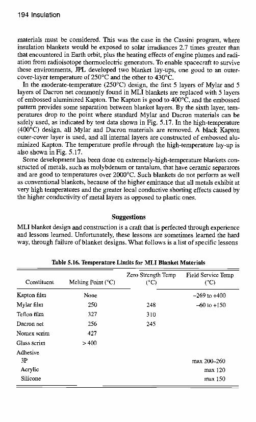
Table 5.16. Temperature Limits for MLI Blanket Materials
Constituent Zero Strength Temp Field Service Temp
Melting Point (°C) (°C) (°C)
Kapton film
Mylar film
Teflon film
Dacron net
Nomex scrim
Glass scrim
Adhesive 3P
Acrylic
Silicone
None
250
327
256
427
> 400
248
310
245
-269 to +400
-60 to + 150
max 200-260
max 120
max 150
Suggestions 195
300 I I I I ~" 250 ~
• 200 L-
o. 100-- E
5 o - 0 I I I I 0
500 5 10 15 20 25
I I I I o ~" 400 ~
"- 3 0 0 - ~ --
E ~ ~ 200-- i ~ - - - - #. l o o -
0 I I 0 5 10 15 20 25
Layer count
Fig. 5.17. Temperature drop through moderate- and high-temperature MLI blankets.
that have been learned and reported by engineers and technicians making blankets for spacecraft programs. These are offered as suggestions to help the reader avoid the numerous pitfalls encountered by others in past thermal-design development efforts.
Design Suggestions
• Avoid developing designs with excessive contouring of blankets to fit the shape of the hardware. Doing so increases the number of seams, leading to more heat loss and higher patterning and fabrication costs. Contouring may enhance the appearance of blankets, but that is about all that can be said in support of it. Note, however, that contouring may sometimes be needed to meet field-of- view requirements.
• Minimize seam length. Check the edge lengths of a box before deciding on a seam between the side and top versus seaming up the four comers. From a sewing standpoint, short seams (four comers) are preferred over long seams (side to the top).
• Make the material lay-up (especially the intemal layers) the same for all blan- kets. Doing so is not always possible, but changing the number of layers is generally more costly than the savings in material costs. Pulling a new lay-up for a blanket (15 to 20 layers) takes two people 2 to 24 hours and ties up one of the blanket-shop tables. During busy periods, blanket lay-ups are pulled after hours (with staff working at overtime rates) to keep the table available for cut- ting, binding, seaming, etc.
• Design the blanket to fit loosely for good and repeatable thermal performance. A laced edge with an underlap enables adjustment to the desired loose fit.
196 Insulation
Therefore, incorporating a laced edge with an underlap into a multiple-blanket design is good practice.
• Allow for blanket shrinkage during cooldown. The outer layer of an efficient thermal blanket can cool 200°C in the shade with a total view of space (150°C of cooling may be seen in an LN2-cooled chamber test). The coefficient of expansion for Kapton, Dacron, and Mylar is approximately 0.00002 cm/cm/ °C. Therefore, 200°C of cooling results in 0.004 cm/cm or 0.4 cm per 100 cm. The shrinkage can be significant for large blankets and must be considered in the blanket design. During thermal vacuum testing, looking through the cham- ber windows after cooldown to check for blankets that appear too taut is strongly encouraged, although there are never enough windows to see all the blankets. If a blanket appears to fit too tight in the test chamber, correct the fit after the test, because the blanket can cool another 50°C in flight and shrink an additional 25%.
• If a blanket requires significant improvement thermally, consider breaking it into two blankets with staggered seams. The seams of the inner blanket can be overlapped and taped, because the outer blanket will be sewn and laced (or attached via Velcro). Because of the overlapping the patterns for the two blan- kets will be different.
• Make a 15-layer blanket by winding a 5-layer blanket around the cylinder 3 times. This is another approach that has been used successfully. It eliminates the through-side seam but the top/bottom seam (attachment to the side) remains and blanket-to-blanket grounds must be added for flight blankets. Sometimes the top/bottom blankets can be a continuation of the side and folded and overlapped to create closure on the top/bottom.
• Do not allow several organizations to do the thermal blanketing. Whoever has responsibility for the spacecraft should have total control. Avoid dividing responsibility for shipping materials, defining blanket interfaces, and perform- ing other tasks. Cost savings will not be gained, and questions may arise about who has final responsibility.
• Minimize the number of blanket lay-up configurations to save fabrication time. • Be alert for particulate contamination problems caused by Velcro. Electrically
conductive Velcro increases the concerns because the particles can cause elec- trical shorts.
• Avoid taped "blanket close-out" designs. They are not compatible with multi- installations. Grounding of the closure tape is also a problem, as is the possibil- ity of blankets coming loose if the tape debonds.
• Bring the blanket designer into the early stages of the development process. Bringing the designer in late results in poor hardware attachment (if any) and insufficient appreciation for the spacecraft configuration, mission, field of view, etc.
Patterning Suggestions • Realize that experience is the best teacher for patterning. Developers learn
through experience to recognize when a geometry is complex enough to require the "throwing paper at the hardware" approach. Preliminary cubical, cylindrical, spherical, and conical patterns can be constructed from drawings
Suggestions 197
or measurements made on the hardware, but experience teaches how to merge these basic blanket shapes into one complex blanket system.
• Eliminate pattern approaches that increase fabrication time. Doing so saves costs and results in simpler designs that are generally more thermally efficient. For example, a blanket for a cylindrical geometry can be made in one piece rather than three separate pieces for the top, bottom, and side. A one-piece for- mat eliminates blanket-to-blanket grounds that would be needed between the three pieces (saves fabrication costs), reduces the length of seams (is thermally more efficient), and requires documentation for one blanket pattern rather than three (saves patterning costs).
• Allow for blanket thickness. After completing the preliminary pattern, add 5 mm at each comer. Extend the edges of a pattern by 5 mm where a seam will be incorporated. Sometimes adding 3 mm of material to hardware surfaces may be appropriate to simulate the blanket thickness.
• Avoid patterning the flight spacecraft with nonflight hardware. Doing so often results in the blankets not fitting with the real hardware.
• Before submitting a pattern for fabrication, check the ground-to-ground spac- ing and ensure the mating seams are the same length.
• Ensure that the internal seams match up correctly. Sometimes the internal seams become numerous. Stenciling letters at the beginning and end of the seam can help make sure the seams match up. This technique helps prevent mistakes but does not replace discussing the details of the pattern with the blanket fabrication technician.
Fabrication Suggestions
• Do not solder lugs to ground braid, because lugs tend to break off after a mini- mum of flexing (working).
• Do not vacuum-deposit aluminum over the scrim backing. If the scrim is suffi- ciently coarse, little electrically conductive islands are created because the deposited aluminum does not bridge over the scrim.
• Periodically check in on the blanket-fabrication progress. • If cutouts are required for cables, apertures, radiators, struts, etc., as they often
are, make sure that their edges are bound. Binding takes longer on curved edges, so the use of square cutouts in place of circles is encouraged. Also, replacing multiple, closely packed circles with a single rectangular cutout will save fabrication time and probably is insignificant thermally because less seam area balances more exposed area. On the pattern near the cutout, provide a note as to the cutout's purpose (e.g., "cable pass-through," "probe-strut exit"). Such a note may help others to understand the pattern for a later reflight application.
• Determine whether X-shaped crossing openings constitute a better thermal approach than a hole for a cable or strut pass-through. After passing the strut or cable through the openings, use ties to snug the blanket around the tube/cable.
• Stamp the part number and serial number on the finished blanket and make sure that the location of the stamp can be seen on the pattern. Position the stamp along the edge, and, because it can be difficult to find on large blankets, locate it near one of the blanket ground points.
198 Insulation
Insulation for In-Atmosphere Applications
Missions involving planetary landers, rovers, or atmospheric probes usually require insulation that performs well in the presence of an atmosphere. MLI may still be required to protect the hardware during an interplanetary cruise, but foam, batt, or aerogel materials are generally added to provide insulation after atmo- spheric entry and landing in situations where ambient pressure is expected to be high enough to substantially degrade MLI performance (Fig. 5.2). If atmospheric pressure and gravity are low enough, simple trapped-gas spaces alone may be suf- ficient to limit heat loss to the surroundings. The underlying principle behind all of these types of insulation is to trap gas within volumes small enough to eliminate convection effects. Total heat transfer is thereby limited to what can conduct through the low-conductivity insulation material and gas and radiate across the insulation through a process of multiple absorptions and emissions within the insulation-material structure.
Batt Insulation
Fiberglass batt insulation, such as Microlite AA, is similar to building insulation and has been used successfully on planetary landers. Shaped batt insulation (Fig. 5.18) can be fabricated on a mold and furnace-fired to the desired shape. An MLI blanket may also be attached to the exterior surface for ease of handling and for improving thermal performance in a vacuum. Performance of this insulation is a function of temperature, the type of gas, and, to some degree, pressure. Figure 5.19 shows the conductivity of Microlite AA fiberglass batt insulation as a func- tion of temperature in an 8-torr CO 2 atmosphere representative of Martian surface conditions. Fiberglass batt densities are typically in the range of 5-25 kg/m 3, with the lower-density versions having the best thermal performance per kilogram.
Fig. 5.18. Shaped batt insulation.
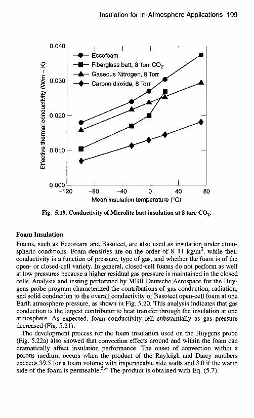
Insulation for In-Atmosphere Applications 199
0.040
I
E ~ 0.030
._z- >
° m
o
"- 0.020-- O o
, , . , _
E L _
t -
I1) > 0.010-- . . . . . .
o
LIJ
0.000 -120
I I I Eccofoam
--I---- Fiberglass batt, 8 Torr CO 2
Gaseous Nitrogen, 8 Torr
- - -~ - - - Carbon dioxide, 8 Torr j
y
I I I I -80 -40 0 40
Mean insulation temperature (°C) 80
Fig. 5.19. Conductivity of Microlite batt insulation at 8 torr CO 2.
Foam Insulation
Foams, such as Eccofoam and Basotect, are also used as insulation under atmo- spheric conditions. Foam densities are on the order of 8-11 kg/m 3, while their conductivity is a function of pressure, type of gas, and whether the foam is of the open- or closed-cell variety. In general, closed-cell foams do not perform as well at low pressures because a higher residual gas pressure is maintained in the closed cells. Analysis and testing performed by MBB Deutsche Aerospace for the Huy- gens probe program characterized the contributions of gas conduction, radiation, and solid conduction to the overall conductivity of Basotect open-cell foam at one Earth atmosphere pressure, as shown in Fig. 5.20. This analysis indicates that gas conduction is the largest contributor to heat transfer through the insulation at one atmosphere. As expected, foam conductivity fell substantially as gas pressure decreased (Fig. 5.21).
The development process for the foam insulation used on the Huygens probe (Fig. 5.22a) also showed that convection effects around and within the foam can dramatically affect insulation performance. The onset of convection within a porous medium occurs when the product of the Rayleigh and Darcy numbers exceeds 39.5 for a foam volume with impermeable side walls and 3.0 if the warm
54 side of the foam is permeable. • The product is obtained with Eq. (5.7).
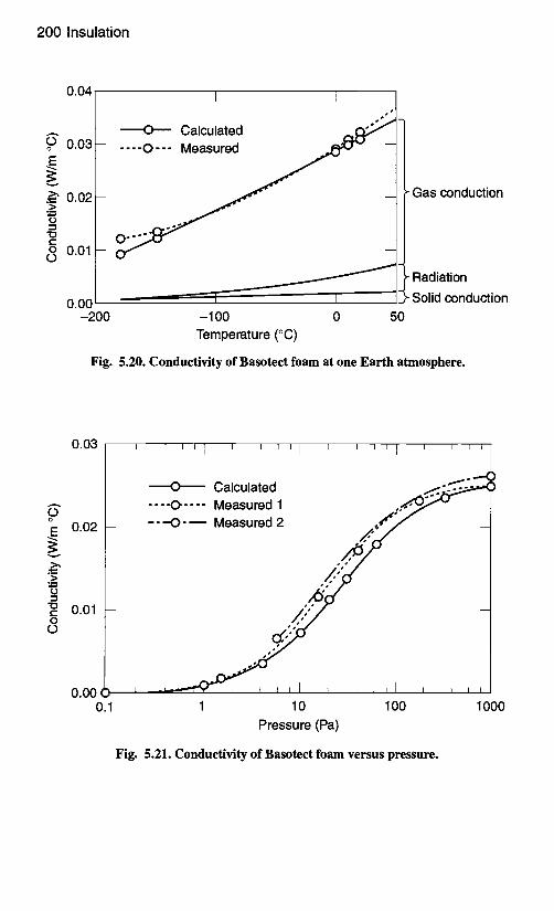
200 Insulation
? E
.>
c - O co
0.04
0.03 --
0.02 --
0.01 --
0.00 -200
I I
- - - -O - . - Calculated . . . . O- - - Measured
-100 Temperature (°C)
0 50
Gas conduction
Radiation
Solid conduction
Fig. 5.20. Conductivity of Basotect foam at one Earth atmosphere.
co o
E
.,..,
.> 0 Z~
" 0 t - O o
0.03
0.02
i i i ~ I i l i i I i J i i I ~ i i i
0.01 O~,,~;,"
0.00 () J J I
0.1 1 10 100 Pressure (Pa)
oO'• Calculated ,¢~,:f:. -...<'-""< . . . . . . . . Measured 1 - - - O - ~ Measured 2 ,.¢~';"
s
I I I
1000
Fig. 5.21. Conductivity of Basotect foam versus pressure.
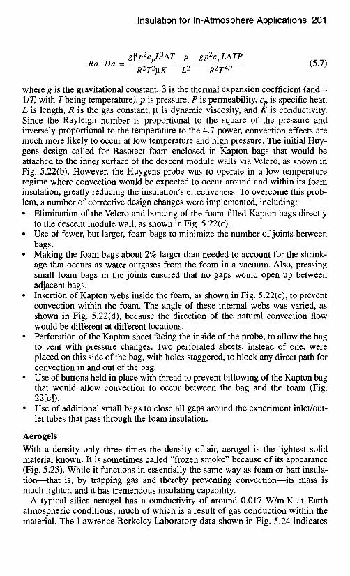
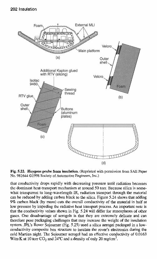
202 Insulation
Fo a m ~~,..,.2........~ External MLI
ITIIII ..... . . . . . .
1 A,.nll
~ " \ Main platform
(a) Ot sh
Velcro
Additional Kapton glued with RTV (slicing)
(b)
I.~ntar.
Sewing thread
Jttons luminum ~tes)
! (c)
(d)
Fig. 5.22. Huygens probe foam insulation. (Reprinted with permission from SAE Paper No. 981644 ©1998 Society of Automotive Engineers, Inc.)
that conductivity drops rapidly with decreasing pressure until radiation becomes the dominant heat-transport mechanism at around 50 torr. Because silica is some- what transparent to long-wavelength IR, radiation transport through the material can be reduced by adding carbon black to the silica. Figure 5.24 shows that adding 9% carbon black (by mass) cuts the overall conductivity of the material in half at low pressure by impeding the radiative heat transport process. An important note is that the conductivity values shown in Fig. 5.24 will differ for atmospheres of other gases. One disadvantage of aerogels is that they are extremely delicate and can therefore pose packaging challenges that may increase the weight of the insulation system. JPL's Rover Sojourner (Fig. 5.25) used a silica aerogel packaged in a low- conductivity composite box structure to insulate the rover's electronics during the cold Martian night. The Sojourner aerogel had an effective conductivity of 0.0163 W/m.K at 10 tort CO 2 and 24°C and a density of only 20 mg/cm 3.
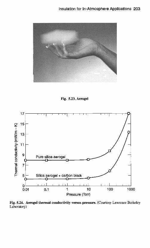
Insulation for In-Atmosphere Appl icat ions 203
Fig. 5.23. Aerogel
17
~, 15 i E ~ 13
E ._~ 11
-~ 9 t - O [
m 7 E e-- ~ 5
(
I I I I I
Pure silica aerogel 1 El n
, , ~ , 1 ~ , i , I ~ i i l l , i , i
1 10 100 1000
Pressure (Torr)
- Silica aerogel + carbon black O O
0 I I I I
0.01 0.1
Fig. 5.24. Aerogel thermal conductivity versus pressure. (Courtesy Lawrence Berkeley Laboratory)
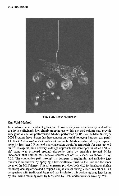
204 Insulation
Fig. 5.25. Rover Sojourner.
Gas Void Method
In situations where ambient gases are of low density and conductivity, and where gravity is sufficiently low, simply trapping gas within a closed volume may provide very good insulation performance. Studies performed by JPL for the Mars Surveyor 2001 Program have shown that free convection should not occur between two paral- lel plates of dimensions 25.4 cm x 25.4 cm on the Martian surface if they are spaced apart by less than 2.3 cm and that convection would be negligible for gaps up to 6
55 cm. • To exploit this discovery, a design approach was developed in which a "dead air" zone was achieved around electronic units by attaching formed Mylar "bumpers" that hold an MLI blanket several cm off the surface, as shown in Fig. 5.26. The conductive path through the bumpers is negligible, and radiative heat transfer is minimized by applying a low-emittance finish to the unit and the inner cover of the MLI blanket. This arrangement provides both MLI for insulation during the interplanetary cruise and a trapped CO 2 insulator during surface operations. In a comparison with traditional foam and batt insulation, this design reduced heat losses by 38% while reducing mass by 60%, cost by 33%, and fabrication time by 75%.
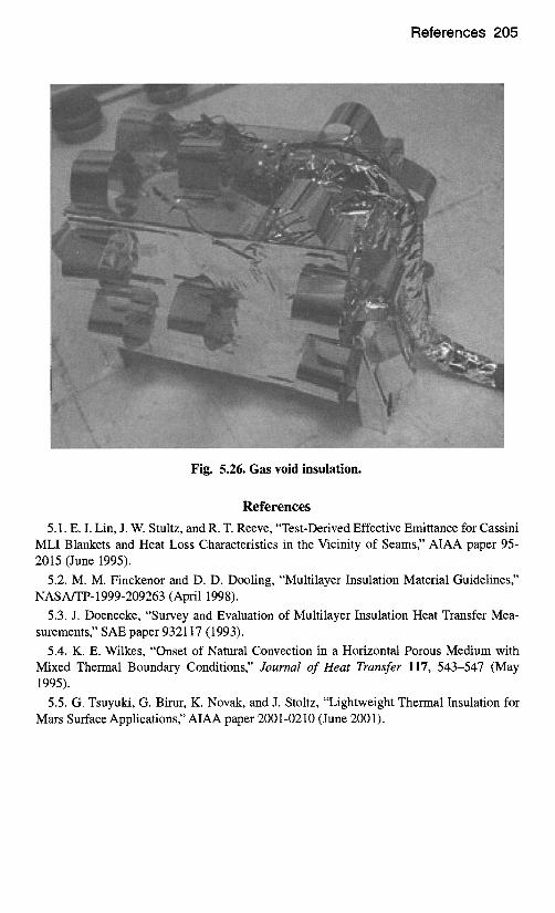
References 205
Fig. 5.26. Gas void insulation.
References
5.1. E. I. Lin, J. W. Stultz, and R. T. Reeve, "Test-Derived Effective Emittance for Cassini MLI Blankets and Heat Loss Characteristics in the Vicinity of Seams" AIAA paper 95- 2015 (June 1995).
5.2. M. M. Finckenor and D. D. Dooling, "Multilayer Insulation Material Guidelines" NASA/TP-1999-209263 (April 1998).
5.3. J. Doenecke, "Survey and Evaluation of Multilayer Insulation Heat Transfer Mea- surements," SAE paper 932117 (1993).
5.4. K. E. Wilkes, "Onset of Natural Convection in a Horizontal Porous Medium with Mixed Thermal Boundary Conditions," Journal of Heat Transfer 117, 543-547 (May 1995).
5.5. G. Tsuyuki, G. Birur, K. Novak, and J. Stoltz, "Lightweight Thermal Insulation for Mars Surface Applications," AIAA paper 2001-0210 (June 2001).