Embed Size (px)
Citation preview
December, 2008 Page 1Course 501 LTE (c)2008 Scott Baxter
Course 501
LTE: Long Term EvolutionFourth Generation WirelessLTE: Long Term Evolution
Fourth Generation Wireless
December, 2008 Page 2Course 501 LTE (c)2008 Scott Baxter
Course Outline
What is LTE?Spectrum and the Development of WirelessOverview of Competing 4th Generation Systems and SpectrumStructure of the LTE RF signals, uplink and downlinkLTE Network Architecture
• All-IP operation• “Flat” Architecture
December, 2008 Page 3Course 501 LTE (c)2008 Scott Baxter
What is LTE?
Fourth generation wireless technologies offer much higher data speeds, much lower latency, more sophisticated Quality-of-Service, lower cost per bit, and simpler/less expensive/more robust network architectures.LTE, Long Term Evolution, is a fourth-generation wireless technology
• Already supported by most US wireless operators as their choice for fourth generation deployment and migration
Two other technologies are also being discussed as potential fourth-generation wireless technologies
• WiMAX – Wireless Interoperability for Microwave Access– based on IEEE standard 802.16, several versions– implemented by Sprint in initial markets in 4Q2008
• UMB – Universal Mobile Broadband– proposed by Qualcomm, based on enhancements of the 1xEV-
DO standard, EVDO rev. B and EVDO rev. C.– Qualcomm withdrew its proposal in early December, 2008 due to
lack of operator interest in implementing it

December, 2008 Page 4Course 501 LTE (c)2008 Scott Baxter
Goals of LTE
Reduce operating expenses (OPEX) and capital expenditures (CAPEX)Dramatically increase data speeds and spectral density compared to 3G technologiesSubstantially reduce latency, to provide superior voice-over IP and other latency-dependent servicesFlatten the network architecture so only two node types (base stations and gateways) are involved, simplifying management and dimensioningProvide a high degree of automatic configuration for the networkahigh degree of automatic configuration.Optimize interworking between CDMA and LTE-SAE so CDMA operators can benefit from huge economies of scale and global chipset volumes
December, 2008 Page 5Course 501 LTE (c)2008 Scott Baxter
Course 501
Spectrum and the Development of Wireless
Spectrum and the Development of Wireless
December, 2008 Page 6Course 501 LTE (c)2008 Scott Baxter
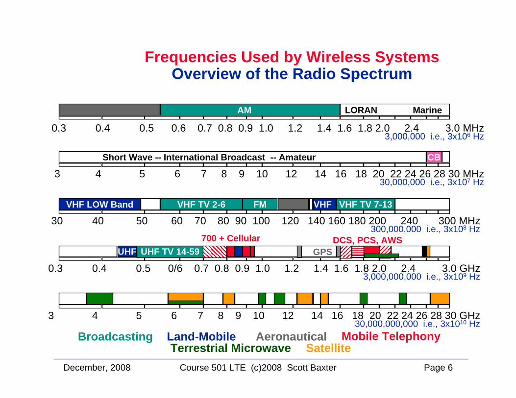
Frequencies Used by Wireless SystemsOverview of the Radio Spectrum
3 4 5 6 7 8 9 10 12 14 16 18 20 22 24 26 28 30 GHz30,000,000,000 i.e., 3x10¹⁰ Hz
Broadcasting Land-Mobile Aeronautical Mobile TelephonyTerrestrial Microwave Satellite
0.3 0.4 0.5 0/6 0.7 0.8 0.9 1.0 1.2 1.4 1.6 1.8 2.0 2.4 3.0 GHz3,000,000,000 i.e., 3x10⁹ Hz
UHF TV 14-59UHF GPSDCS, PCS, AWS700 + Cellular
0.3 0.4 0.5 0.6 0.7 0.8 0.9 1.0 1.2 1.4 1.6 1.8 2.0 2.4 3.0 MHz3,000,000 i.e., 3x10⁶ Hz
AM LORAN Marine
3 4 5 6 7 8 9 10 12 14 16 18 20 22 24 26 28 30 MHz30,000,000 i.e., 3x10⁷ Hz
Short Wave -- International Broadcast -- Amateur CB
30 40 50 60 70 80 90 100 120 140 160 180 200 240 300 MHz300,000,000 i.e., 3x10⁸ Hz
FM VHF TV 7-13VHF LOW Band VHFVHF TV 2-6
December, 2008 Page 7Course 501 LTE (c)2008 Scott Baxter
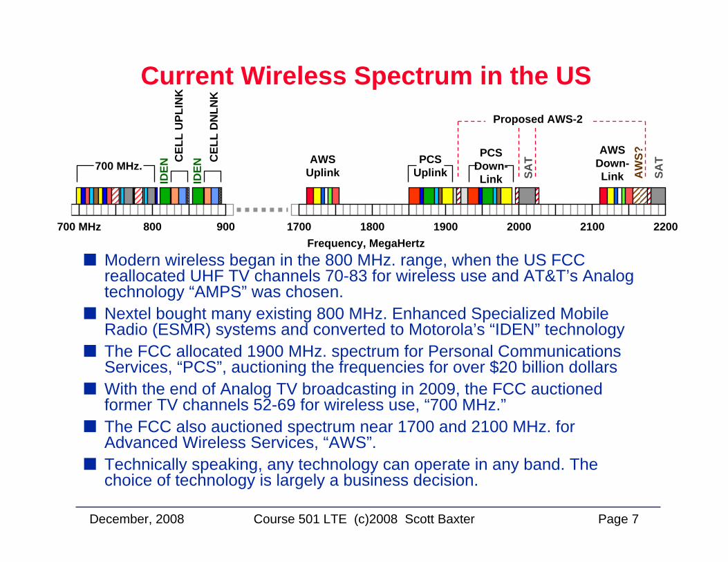
Current Wireless Spectrum in the US
Modern wireless began in the 800 MHz. range, when the US FCC reallocated UHF TV channels 70-83 for wireless use and AT&T’s Analog technology “AMPS” was chosen.Nextel bought many existing 800 MHz. Enhanced Specialized MobileRadio (ESMR) systems and converted to Motorola’s “IDEN” technologyThe FCC allocated 1900 MHz. spectrum for Personal CommunicationsServices, “PCS”, auctioning the frequencies for over $20 billion dollarsWith the end of Analog TV broadcasting in 2009, the FCC auctioned former TV channels 52-69 for wireless use, “700 MHz.”The FCC also auctioned spectrum near 1700 and 2100 MHz. for Advanced Wireless Services, “AWS”. Technically speaking, any technology can operate in any band. The choice of technology is largely a business decision.
700 MHz 800 900 1700 1800 1900 2000 2100 2200
700 MHz.ID
EN
IDEN
CEL
L D
NLN
K
CEL
L U
PLIN
K
AWSUplink
AWSDown-Link
PCSUplink
PCSDown-Link
Proposed AWS-2
AW
S?
SAT
SAT
Frequency, MegaHertz
December, 2008 Page 8Course 501 LTE (c)2008 Scott Baxter
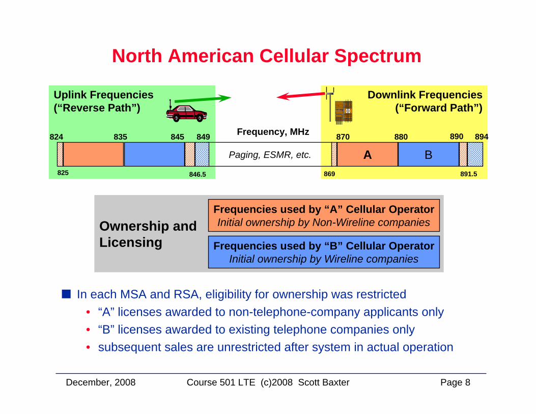
North American Cellular Spectrum
In each MSA and RSA, eligibility for ownership was restricted• “A” licenses awarded to non-telephone-company applicants only• “B” licenses awarded to existing telephone companies only • subsequent sales are unrestricted after system in actual operation
Downlink Frequencies(“Forward Path”)
Uplink Frequencies(“Reverse Path”)
Frequency, MHz824 835 845 870 880 894
869
849
846.5825
890
891.5
Paging, ESMR, etc. A B
Ownership andLicensing
Frequencies used by “A” Cellular OperatorInitial ownership by Non-Wireline companies
Frequencies used by “B” Cellular OperatorInitial ownership by Wireline companies
December, 2008 Page 9Course 501 LTE (c)2008 Scott Baxter
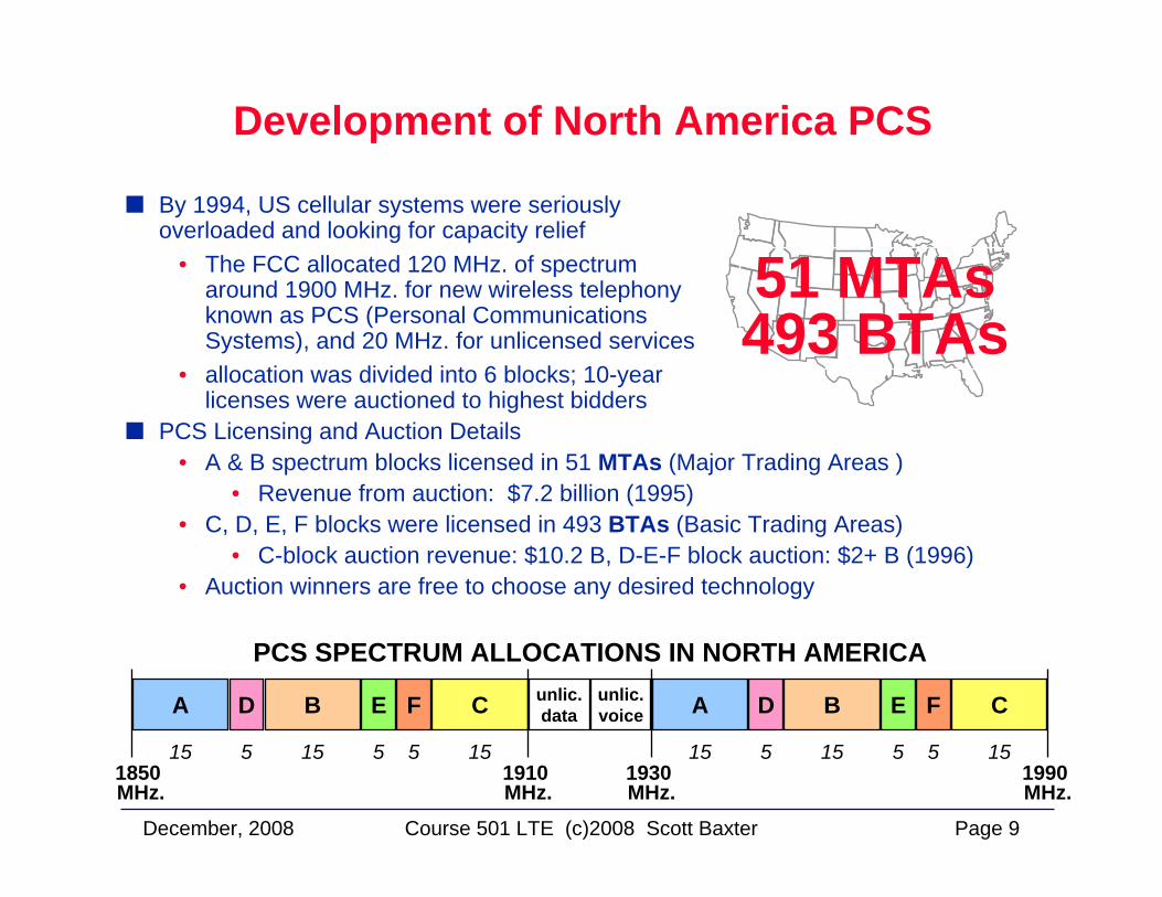
By 1994, US cellular systems were seriously overloaded and looking for capacity relief
• The FCC allocated 120 MHz. of spectrum around 1900 MHz. for new wireless telephony known as PCS (Personal Communications Systems), and 20 MHz. for unlicensed services
• allocation was divided into 6 blocks; 10-year licenses were auctioned to highest bidders
Development of North America PCS
51 MTAs493 BTAs
PCS Licensing and Auction Details• A & B spectrum blocks licensed in 51 MTAs (Major Trading Areas )
• Revenue from auction: $7.2 billion (1995) • C, D, E, F blocks were licensed in 493 BTAs (Basic Trading Areas)
• C-block auction revenue: $10.2 B, D-E-F block auction: $2+ B (1996)• Auction winners are free to choose any desired technology
A D B E F C unlic.data
unlic.voice A D B E F C
1850 MHz.
1910 MHz.
1990 MHz.
1930 MHz.
15 15 155 5 5 15 15 155 5 5
PCS SPECTRUM ALLOCATIONS IN NORTH AMERICA
December, 2008 Page 10Course 501 LTE (c)2008 Scott Baxter
Potential Spectrum for LTE
LTE Potential SpectrumLTE and WIMAX have their own benefits and are suited to address different target market segments; one of the key differentiator is that WiMAX is primarily TDD (Time-Division-Duplex) and will address operators that have unpaired spectrum whereas LTE is FDD (Frequency-Division-Duplex) and will address operators that have paired spectrum. Time Division Duplexing allows the up-link and down-link to share the same spectrum where as Frequency Division Duplexing allows that the up-link and down-link to transmit on different frequencies. 3GGP LTE standards are planned for completion by beginning of 2008, and the industry believes the first deployments of LTE network are likely to take place at the end of 2009, beginning of 2010.In the section, we will look at the most probable FDD spectrum bands suitable for the future deployment of LTE but bearing in mind the above mentioned schedule and the current level of activity related to spectrum regulation and allocation, it is likely that the information contained in this paper will require regular revision to remain accurate.
December, 2008 Page 11Course 501 LTE (c)2008 Scott Baxter
The US 700 MHz. Spectrum and Its Blocks
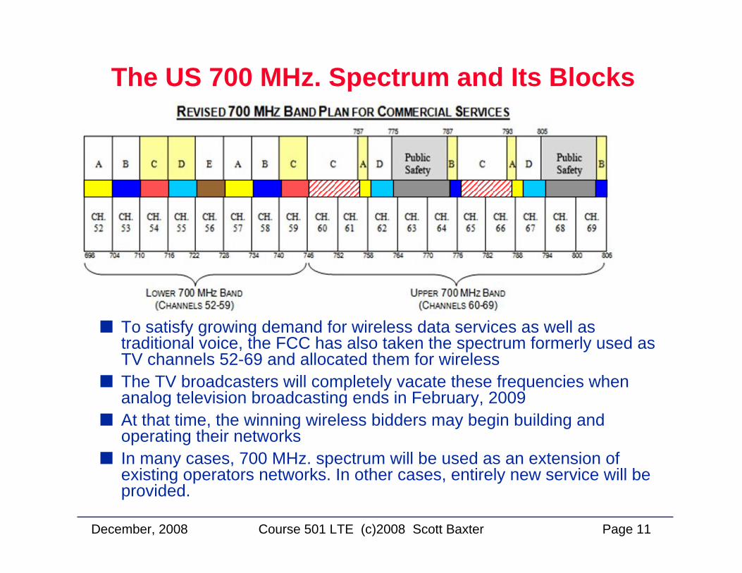
To satisfy growing demand for wireless data services as well as traditional voice, the FCC has also taken the spectrum formerly used as TV channels 52-69 and allocated them for wirelessThe TV broadcasters will completely vacate these frequencies when analog television broadcasting ends in February, 2009At that time, the winning wireless bidders may begin building and operating their networksIn many cases, 700 MHz. spectrum will be used as an extension ofexisting operators networks. In other cases, entirely new service will be provided.
December, 2008 Page 12Course 501 LTE (c)2008 Scott Baxter
The 700 MHz. Band in the US
700 MHzIn the U.S. this commercial spectrum was auctioned in April 2008. The auction included 62 MHz of spectrum broken into 4 blocks; Lower A (12 MHz), Lower B (12 MHz), Lower E (6 MHz unpaired) , Upper C (22 MHz), Upper D (10 MHz). These bands are highly prized chunks of spectrum and a tremendous resource: the low frequency is efficient and will allow for a network that doesn’t require a dense buildout and provides better in-building penetration than higher frequency bands.The Digital Television Transition and Public Safety Act of 2005 sets February 17, 2009 as the date that all U.S. TV stations must vacate the 700 MHz spectrum, making it fully available for new services.
• The upper C block came along with “open access” rules. In the FCC’s context “open access” means that there would be “no locking and no blocking” by the network operator. That is, the licensee must allow any device to be connected to the network so long as the devices arecompatible with, and do not harm the network (i.e., no “locking”), and cannot impose restrictions against content, applications, or services that may be accessed over the network (i.e., no “blocking”). The upper D block did not meet the $1.3 billion reserve price. This spectrum will likely be reauctioned in the future with a new set of requirements that could give rise to a licensee capable of addressing first responders’interoperability and broadband requirements.
Indications are strong that similar transitions may occur in other parts of the world, possibly allowing global roaming on compatible bands.
December, 2008 Page 13Course 501 LTE (c)2008 Scott Baxter
Advanced Wireless Services Spectrum
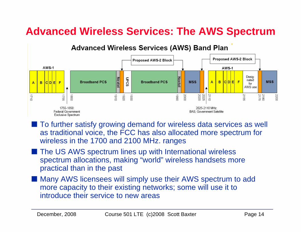
Advanced Wireless Services (AWS)In September 2006 the FCC completed an auction of AWS licenses (“Auction No. 66”) in which the winning bidders won a total of 1,087 licenses. In the spirit of the U.S. government’s free-market policies, the FCC does not usually mandate that specific technologies be used in specific bands. Therefore, owners of AWS spectrum are free to use it for just about any 2G, 3G or 4G, technology.This spectrum uses 1.710-1.755 GHz for the uplink and 2.110-2.155 GHz for the downlink.90 MHz of spectrum divided this into six frequency blocks A through F. Blocks A, B, and F are 20 megahertz each and blocks C, D, and E, are 10 megahertz each.The FCC wanted to harmonized its “new” AWS spectrum as closely as possible with Europe’s UMTS 2100 band. However, the lower half of Europe’s UMTS 2100 band almost completely overlaps with the U.S PCS band, so complete harmonization wasn’t an option. Given the constraint the FCC harmonized AWS as much as possible with the rest of the world. The upper AWS band lines up with Europe’s UMTS 2100 base transmit band, and the lower AWS band aligns with Europe’s GSM 1800 mobile transmit band.
December, 2008 Page 14Course 501 LTE (c)2008 Scott Baxter
Advanced Wireless Services: The AWS Spectrum
To further satisfy growing demand for wireless data services as well as traditional voice, the FCC has also allocated more spectrum for wireless in the 1700 and 2100 MHz. rangesThe US AWS spectrum lines up with International wireless spectrum allocations, making “world” wireless handsets more practical than in the pastMany AWS licensees will simply use their AWS spectrum to add more capacity to their existing networks; some will use it to introduce their service to new areas
December, 2008 Page 15Course 501 LTE (c)2008 Scott Baxter
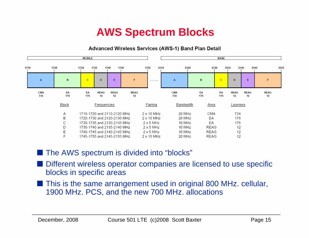
AWS Spectrum Blocks
The AWS spectrum is divided into “blocks”Different wireless operator companies are licensed to use specific blocks in specific areasThis is the same arrangement used in original 800 MHz. cellular,1900 MHz. PCS, and the new 700 MHz. allocations
December, 2008 Page 16Course 501 LTE (c)2008 Scott Baxter
AWS Spectrum Winners
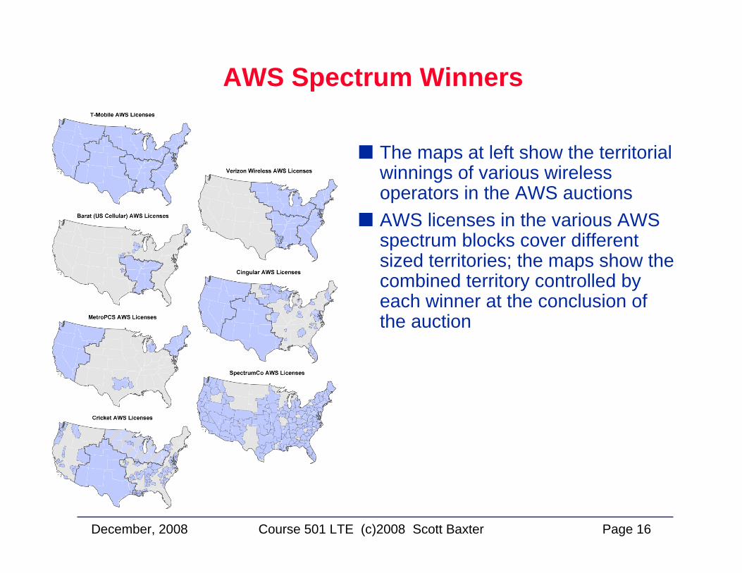
The maps at left show the territorial winnings of various wireless operators in the AWS auctionsAWS licenses in the various AWS spectrum blocks cover different sized territories; the maps show the combined territory controlled by each winner at the conclusion of the auction
December, 2008 Page 17Course 501 LTE (c)2008 Scott Baxter
Global Wireless Frequency AllocationsAvailable for 4G Technologies
December, 2008 Page 18Course 501 LTE (c)2008 Scott Baxter
Current Wireless Technologiesand New Directions for 4G
Current Wireless Technologiesand New Directions for 4G
December, 2008 Page 19Course 501 LTE (c)2008 Scott Baxter
Multiple Access Methods
FrequencyTime
Power
TDMA
Frequency
Time
Power
FDMA
FrequencyTime
Power
CDMA
CODE
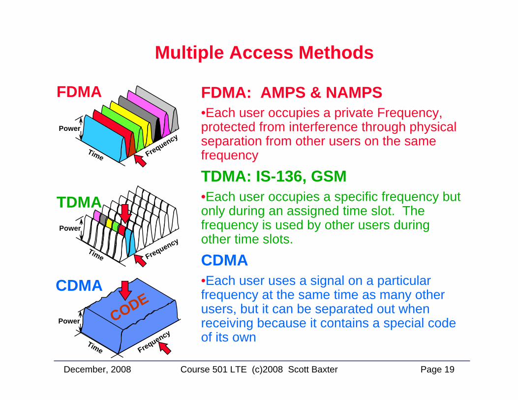
FDMA: AMPS & NAMPS•Each user occupies a private Frequency, protected from interference through physical separation from other users on the same frequency
TDMA: IS-136, GSM•Each user occupies a specific frequency but only during an assigned time slot. The frequency is used by other users during other time slots.
CDMA•Each user uses a signal on a particular frequency at the same time as many other users, but it can be separated out when receiving because it contains a special code of its own
December, 2008 Page 20Course 501 LTE (c)2008 Scott Baxter
Multiple Access Methods
MIMO
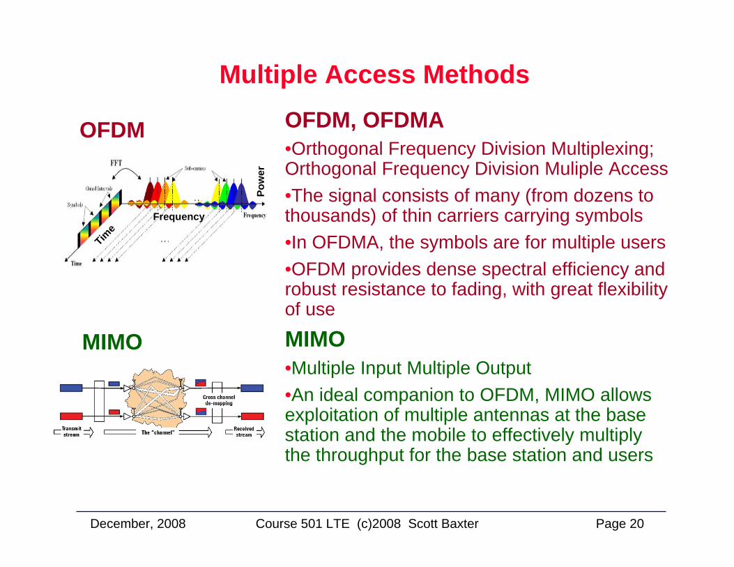
OFDM OFDM, OFDMA •Orthogonal Frequency Division Multiplexing; Orthogonal Frequency Division Muliple Access•The signal consists of many (from dozens to thousands) of thin carriers carrying symbols•In OFDMA, the symbols are for multiple users•OFDM provides dense spectral efficiency and robust resistance to fading, with great flexibility of use
MIMO•Multiple Input Multiple Output•An ideal companion to OFDM, MIMO allows exploitation of multiple antennas at the base station and the mobile to effectively multiply the throughput for the base station and users
Frequency
Time
Pow
er
December, 2008 Page 21Course 501 LTE (c)2008 Scott Baxter
A Technical ComparisonLTE, WiMax, UMB
A Technical ComparisonLTE, WiMax, UMB
December, 2008 Page 22Course 501 LTE (c)2008 Scott Baxter
LTE
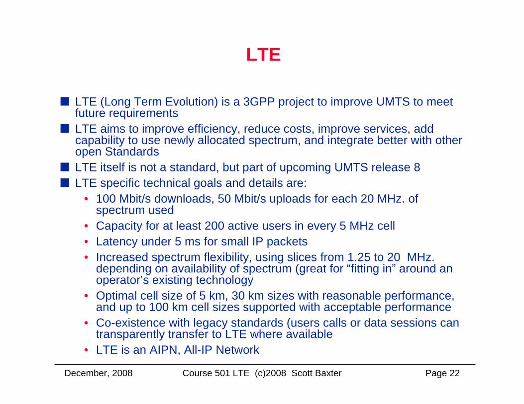
LTE (Long Term Evolution) is a 3GPP project to improve UMTS to meet future requirementsLTE aims to improve efficiency, reduce costs, improve services, add capability to use newly allocated spectrum, and integrate better with other open StandardsLTE itself is not a standard, but part of upcoming UMTS release 8LTE specific technical goals and details are:
• 100 Mbit/s downloads, 50 Mbit/s uploads for each 20 MHz. of spectrum used
• Capacity for at least 200 active users in every 5 MHz cell• Latency under 5 ms for small IP packets• Increased spectrum flexibility, using slices from 1.25 to 20 MHz.
depending on availability of spectrum (great for “fitting in” around an operator’s existing technology
• Optimal cell size of 5 km, 30 km sizes with reasonable performance, and up to 100 km cell sizes supported with acceptable performance
• Co-existence with legacy standards (users calls or data sessions can transparently transfer to LTE where available
• LTE is an AIPN, All-IP Network
December, 2008 Page 23Course 501 LTE (c)2008 Scott Baxter
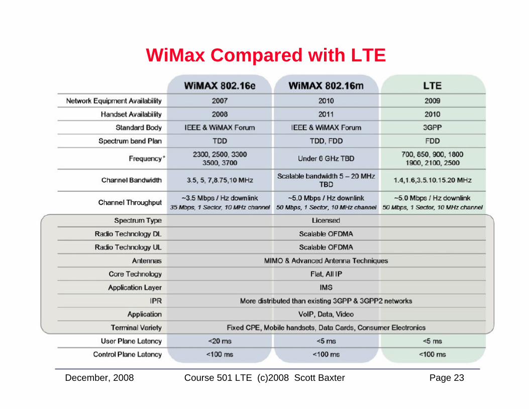
WiMax Compared with LTE
December, 2008 Page 24Course 501 LTE (c)2008 Scott Baxter
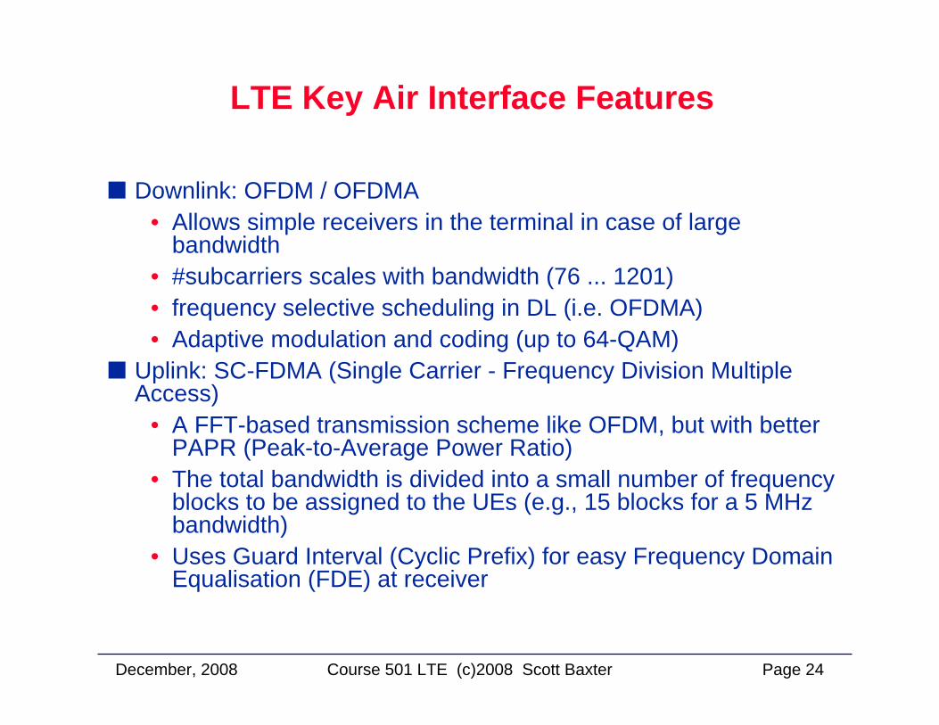
LTE Key Air Interface Features
Downlink: OFDM / OFDMA• Allows simple receivers in the terminal in case of large
bandwidth• #subcarriers scales with bandwidth (76 ... 1201)• frequency selective scheduling in DL (i.e. OFDMA)• Adaptive modulation and coding (up to 64-QAM)
Uplink: SC-FDMA (Single Carrier - Frequency Division Multiple Access)
• A FFT-based transmission scheme like OFDM, but with better PAPR (Peak-to-Average Power Ratio)
• The total bandwidth is divided into a small number of frequency blocks to be assigned to the UEs (e.g., 15 blocks for a 5 MHz bandwidth)
• Uses Guard Interval (Cyclic Prefix) for easy Frequency Domain Equalisation (FDE) at receiver
December, 2008 Page 25Course 501 LTE (c)2008 Scott Baxter
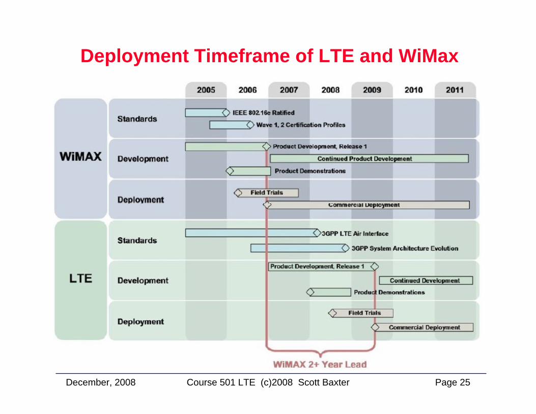
Deployment Timeframe of LTE and WiMax
December, 2008 Page 26Course 501 LTE (c)2008 Scott Baxter
UMB
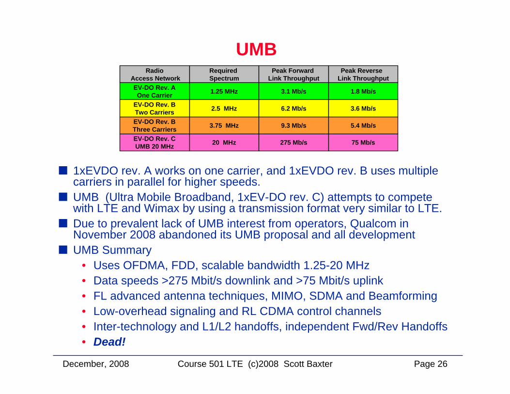
1xEVDO rev. A works on one carrier, and 1xEVDO rev. B uses multiple carriers in parallel for higher speeds.UMB (Ultra Mobile Broadband, 1xEV-DO rev. C) attempts to compete with LTE and Wimax by using a transmission format very similar to LTE.Due to prevalent lack of UMB interest from operators, Qualcom in November 2008 abandoned its UMB proposal and all developmentUMB Summary
• Uses OFDMA, FDD, scalable bandwidth 1.25-20 MHz• Data speeds >275 Mbit/s downlink and >75 Mbit/s uplink• FL advanced antenna techniques, MIMO, SDMA and Beamforming• Low-overhead signaling and RL CDMA control channels• Inter-technology and L1/L2 handoffs, independent Fwd/Rev Handoffs• Dead!
RadioAccess Network
Required Spectrum
Peak Forward Link Throughput
Peak Reverse Link Throughput
EV-DO Rev. AOne Carrier 1.25 MHz 3.1 Mb/s 1.8 Mb/s
EV-DO Rev. BTwo Carriers 2.5 MHz 6.2 Mb/s 3.6 Mb/s
EV-DO Rev. BThree Carriers 3.75 MHz 9.3 Mb/s 5.4 Mb/s
EV-DO Rev. CUMB 20 MHz 20 MHz 275 Mb/s 75 Mb/s
December, 2008 Page 27Course 501 LTE (c)2008 Scott Baxter
LTE: Long-Term EvolutionLTE: Long-Term Evolution
December, 2008 Page 28Course 501 LTE (c)2008 Scott Baxter
The LTE Air Interface:Forward Link (Downlink)The LTE Air Interface:
Forward Link (Downlink)
December, 2008 Page 29Course 501 LTE (c)2008 Scott Baxter
The LTE Downlink Signal
The LTE signal (also known as E-UTRA) uses OFDMA modulation for the downlink and Single Carrier FDMA (SC-FDMA) for the uplinkAn OFDM signal consists of dozens to thousands of very thin carriers, spaced through available spectrum
• each carries a part of the signal• the number of carriers can be adjusted to fit in the available spectrum
OFDM has a Link spectral efficiency greater than CDMA• Using QPSK, 1QAM, and 64QAM modulation along with MIMO, E-
UTRA is much more efficient than WCDMA with HSDPA and HSUPA.LTE Downlink Signal Specifics
• OFDM subcarrier spacing is 15 kHz and the maximum number of carriers is 2048
• 2048 carriers fill 30.7 MHz., 72 subcarriers fill 1.08 MHz.• Mobiles must be capable of receiving 2048 subcarriers but BTS can
transmit as few as 72 carriers when available spectrum is restricted• Time slots are 0.5 ms, subframes 1.0 ms, a radio frame is 10 ms long• MIMO is applied both for single users and for multi-users to boost cell
throughput
December, 2008 Page 30Course 501 LTE (c)2008 Scott Baxter
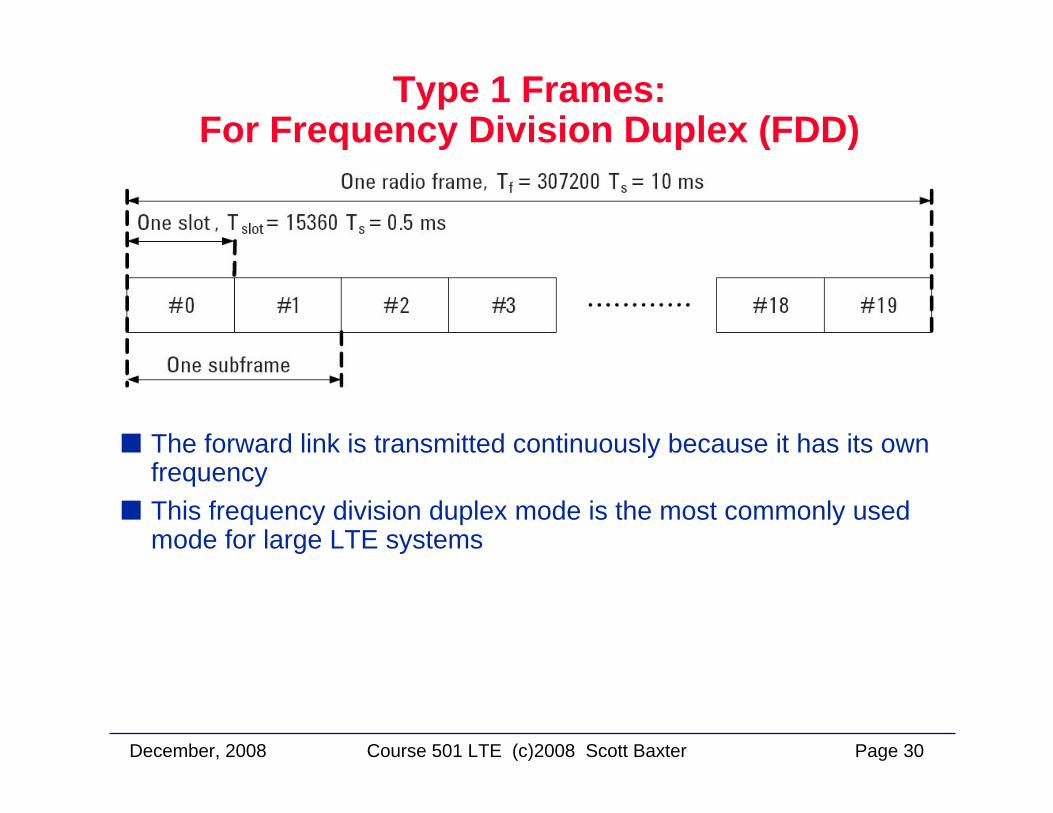
Type 1 Frames: For Frequency Division Duplex (FDD)
The forward link is transmitted continuously because it has its own frequencyThis frequency division duplex mode is the most commonly used mode for large LTE systems
December, 2008 Page 31Course 501 LTE (c)2008 Scott Baxter
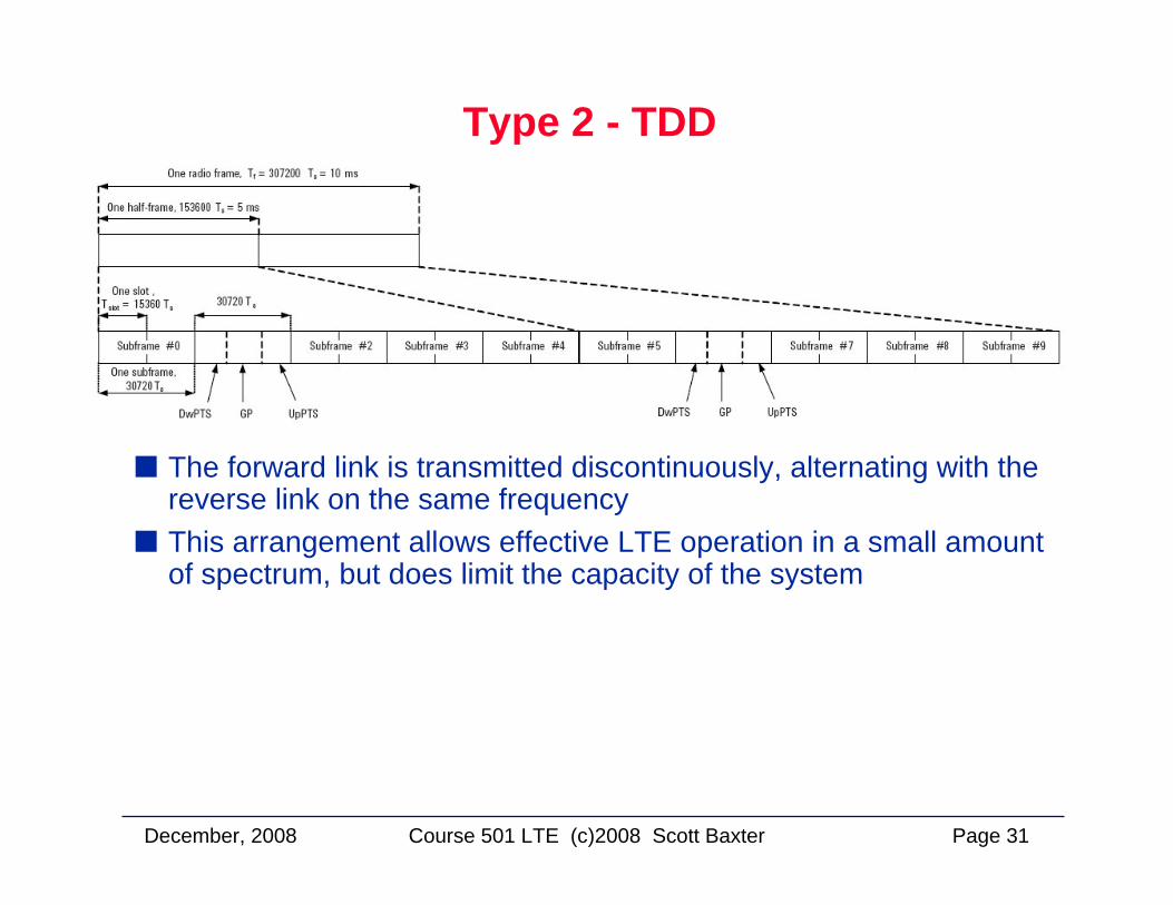
Type 2 - TDD
The forward link is transmitted discontinuously, alternating with the reverse link on the same frequencyThis arrangement allows effective LTE operation in a small amount of spectrum, but does limit the capacity of the system
December, 2008 Page 32Course 501 LTE (c)2008 Scott Baxter
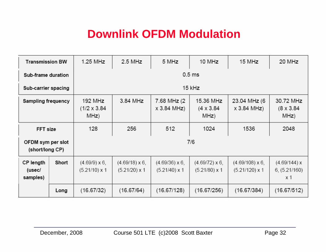
Downlink OFDM Modulation
December, 2008 Page 33Course 501 LTE (c)2008 Scott Baxter
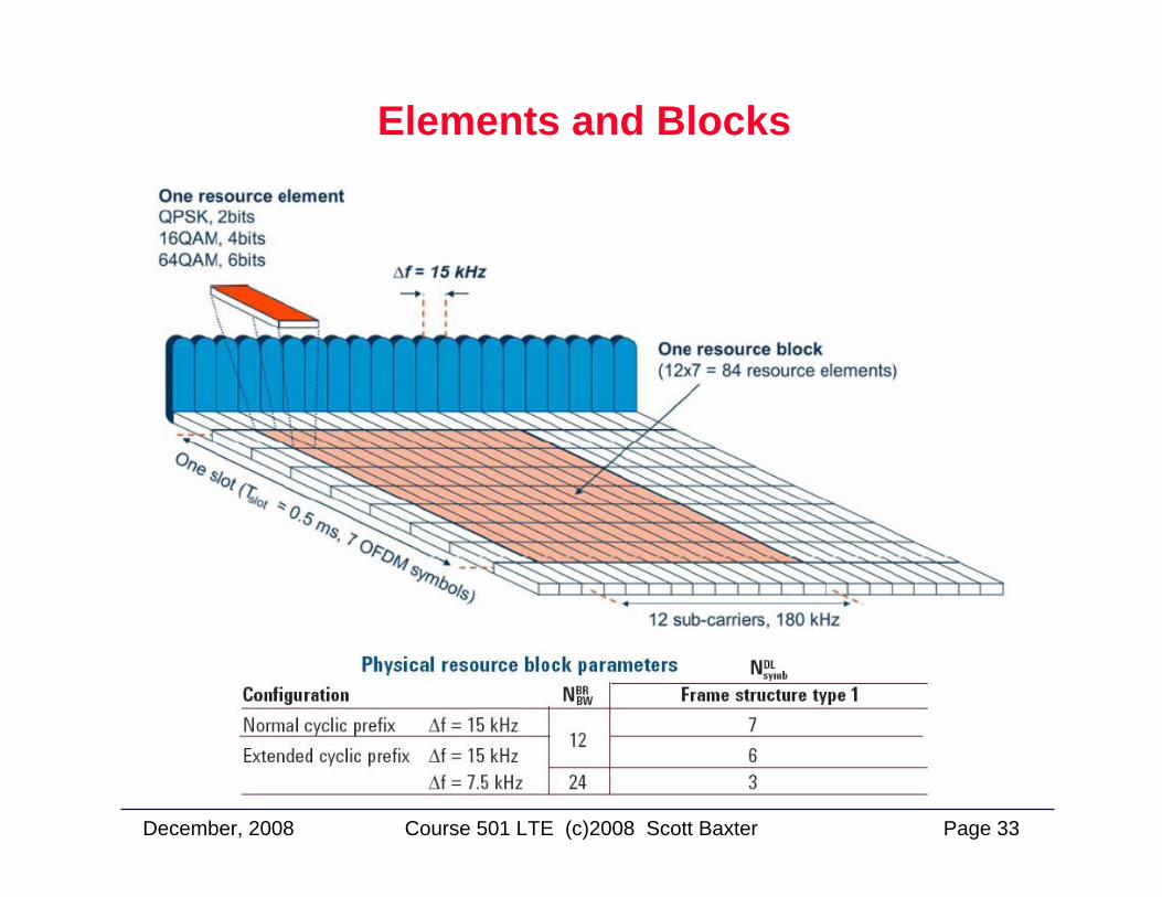
Elements and Blocks
December, 2008 Page 34Course 501 LTE (c)2008 Scott Baxter
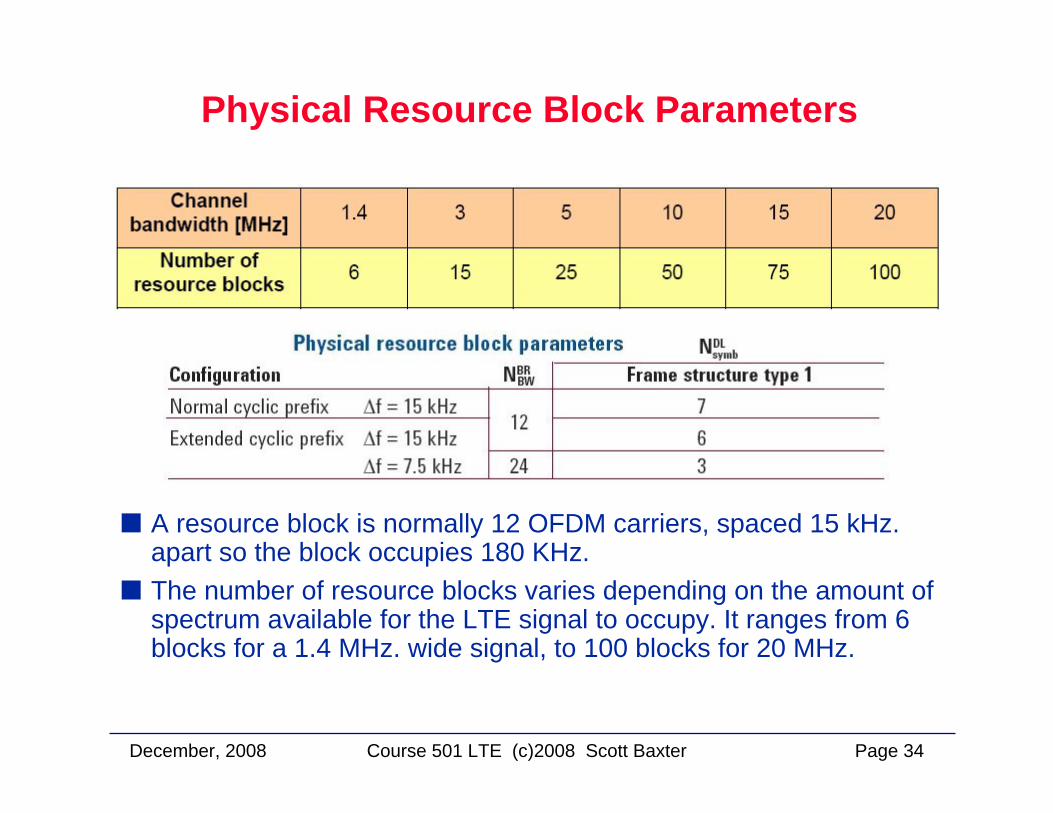
Physical Resource Block Parameters
A resource block is normally 12 OFDM carriers, spaced 15 kHz. apart so the block occupies 180 KHz.The number of resource blocks varies depending on the amount of spectrum available for the LTE signal to occupy. It ranges from 6 blocks for a 1.4 MHz. wide signal, to 100 blocks for 20 MHz.
December, 2008 Page 35Course 501 LTE (c)2008 Scott Baxter
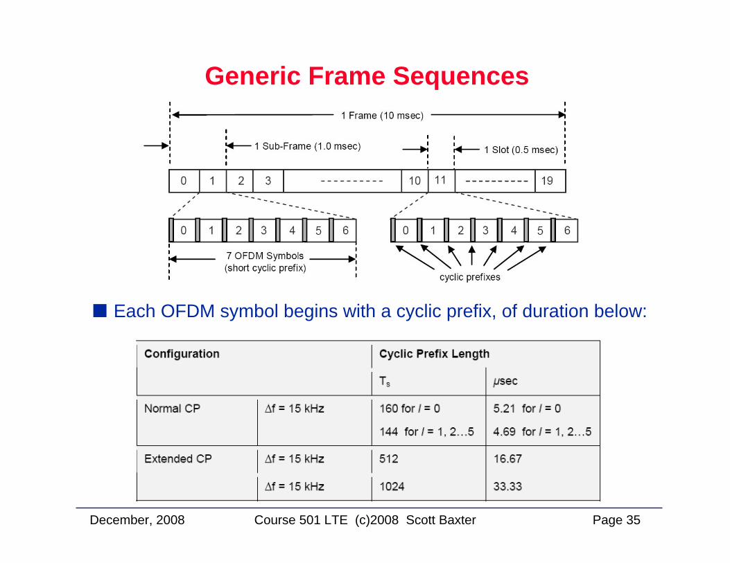
Generic Frame Sequences
Each OFDM symbol begins with a cyclic prefix, of duration below:
December, 2008 Page 36Course 501 LTE (c)2008 Scott Baxter
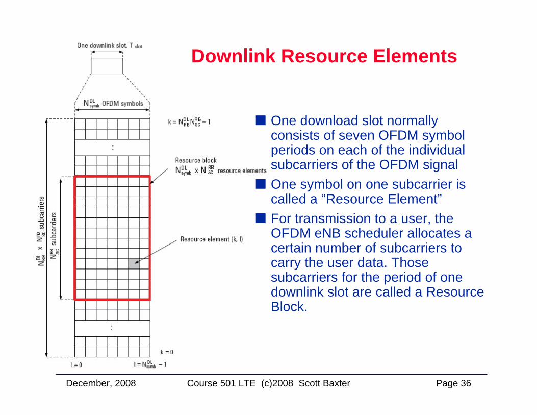
Downlink Resource Elements
One download slot normally consists of seven OFDM symbol periods on each of the individual subcarriers of the OFDM signalOne symbol on one subcarrier is called a “Resource Element”For transmission to a user, the OFDM eNB scheduler allocates a certain number of subcarriers to carry the user data. Those subcarriers for the period of one downlink slot are called a Resource Block.
December, 2008 Page 37Course 501 LTE (c)2008 Scott Baxter
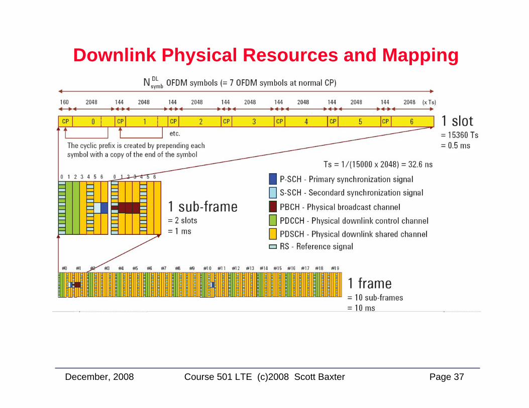
Downlink Physical Resources and Mapping
December, 2008 Page 38Course 501 LTE (c)2008 Scott Baxter
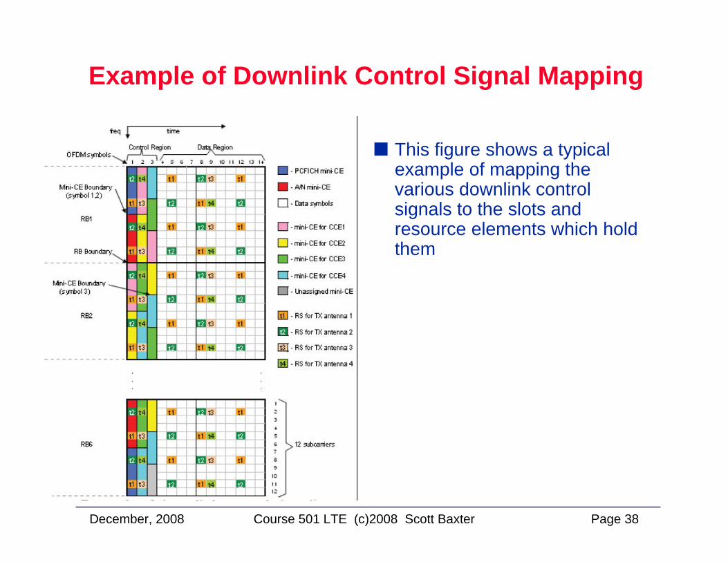
Example of Downlink Control Signal Mapping
This figure shows a typical example of mapping the various downlink control signals to the slots and resource elements which hold them
December, 2008 Page 39Course 501 LTE (c)2008 Scott Baxter
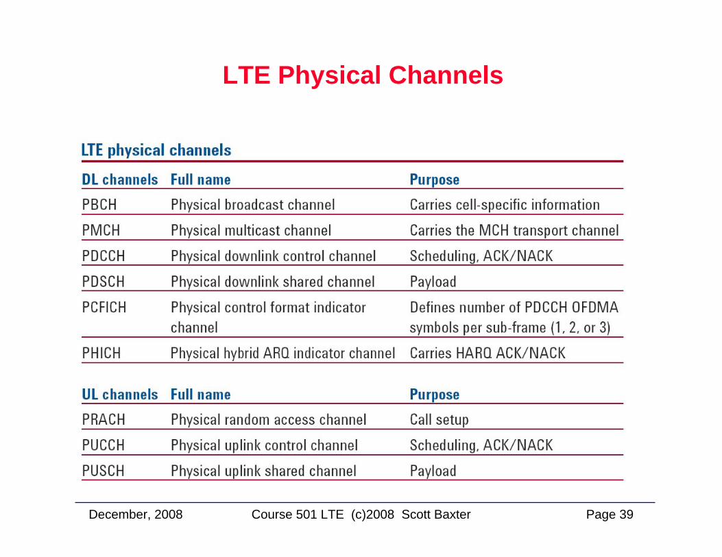
LTE Physical Channels
December, 2008 Page 40Course 501 LTE (c)2008 Scott Baxter
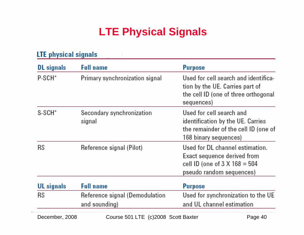
LTE Physical Signals
December, 2008 Page 41Course 501 LTE (c)2008 Scott Baxter
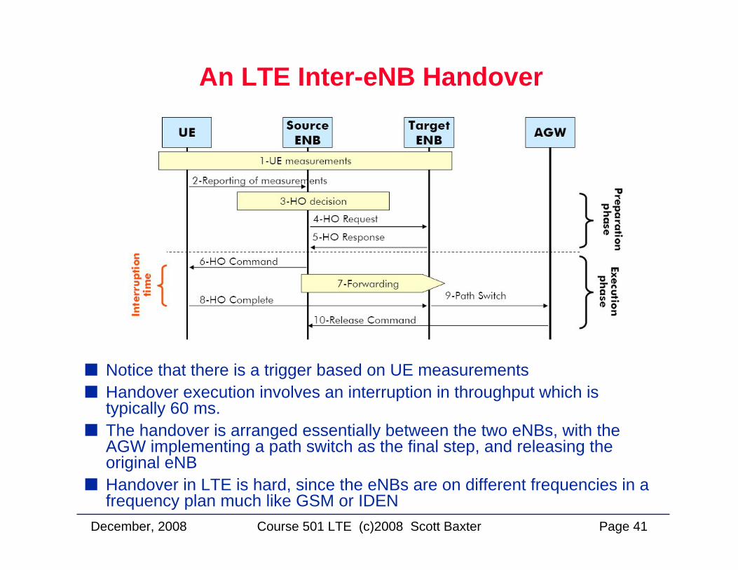
An LTE Inter-eNB Handover
Notice that there is a trigger based on UE measurementsHandover execution involves an interruption in throughput which is typically 60 ms.The handover is arranged essentially between the two eNBs, with the AGW implementing a path switch as the final step, and releasing the original eNBHandover in LTE is hard, since the eNBs are on different frequencies in a frequency plan much like GSM or IDEN
December, 2008 Page 42Course 501 LTE (c)2008 Scott Baxter
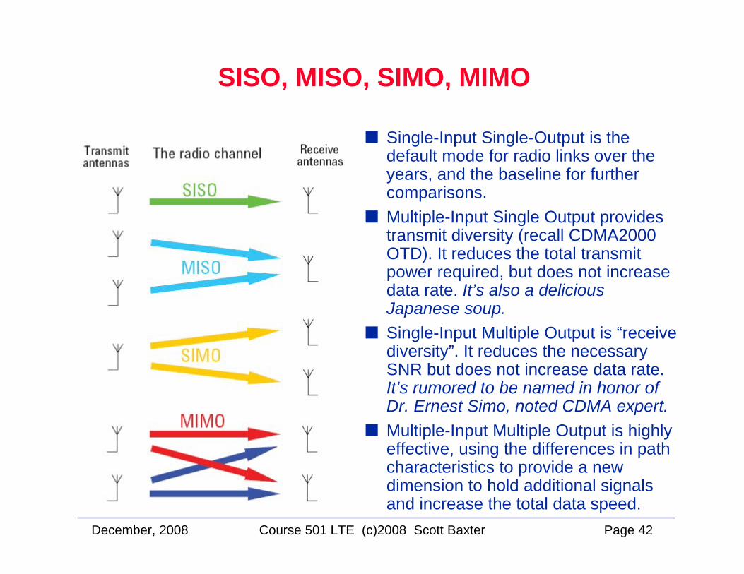
SISO, MISO, SIMO, MIMO
Single-Input Single-Output is the default mode for radio links over the years, and the baseline for further comparisons. Multiple-Input Single Output provides transmit diversity (recall CDMA2000 OTD). It reduces the total transmit power required, but does not increase data rate. It’s also a delicious Japanese soup. Single-Input Multiple Output is “receive diversity”. It reduces the necessary SNR but does not increase data rate. It’s rumored to be named in honor of Dr. Ernest Simo, noted CDMA expert.Multiple-Input Multiple Output is highly effective, using the differences in path characteristics to provide a new dimension to hold additional signals and increase the total data speed.
December, 2008 Page 43Course 501 LTE (c)2008 Scott Baxter
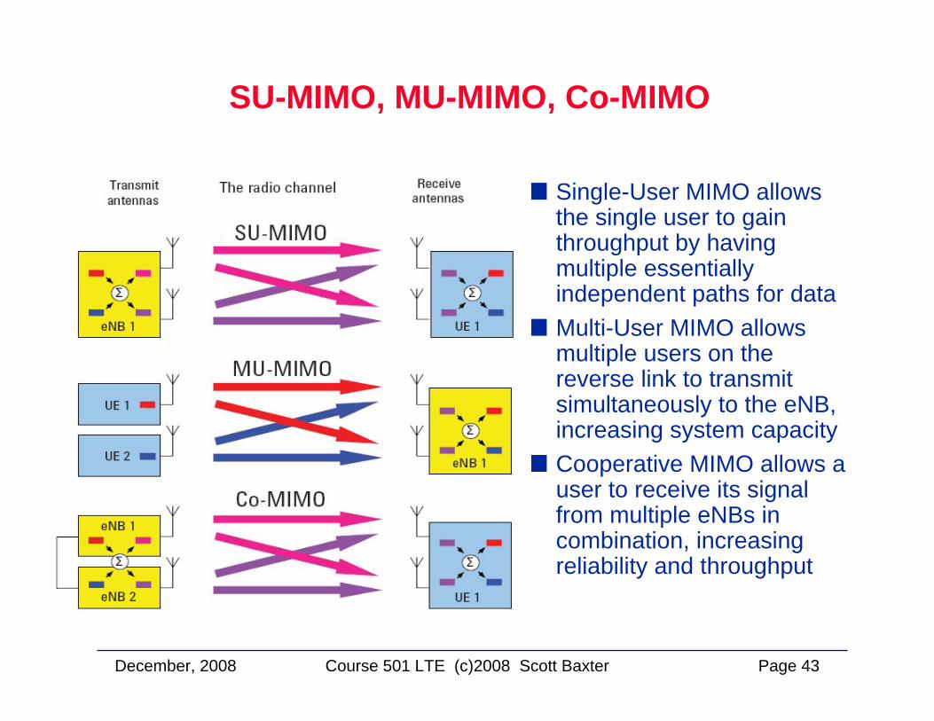
SU-MIMO, MU-MIMO, Co-MIMO
Single-User MIMO allows the single user to gain throughput by having multiple essentially independent paths for dataMulti-User MIMO allows multiple users on the reverse link to transmit simultaneously to the eNB, increasing system capacityCooperative MIMO allows a user to receive its signal from multiple eNBs in combination, increasing reliability and throughput
December, 2008 Page 44Course 501 LTE (c)2008 Scott Baxter
The LTE Air Interface:Reverse Link (Uplink)The LTE Air Interface:Reverse Link (Uplink)
December, 2008 Page 45Course 501 LTE (c)2008 Scott Baxter
The LTE Uplink Signal
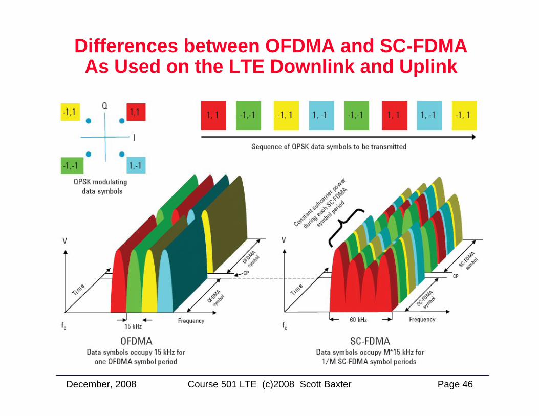
LTE Uplink Signal Specifics• The uplink uses SC-FDMA multiplexing, and QPSK or 16QAM
(64QAM optional) modulation. • SC-FDMA has a low Peak-to-Average Power Ratio (PAPR)
Each mobile has at least one transmitter. • If virtual MIMO / Spatial division multiple access (SDMA) is
introduced the data rate in the uplink direction can be increased depending on the number of antennas at the base station (1 to 4)
• With this technology more than one mobile can reuse the same resources
December, 2008 Page 46Course 501 LTE (c)2008 Scott Baxter
Differences between OFDMA and SC-FDMAAs Used on the LTE Downlink and Uplink
December, 2008 Page 47Course 501 LTE (c)2008 Scott Baxter
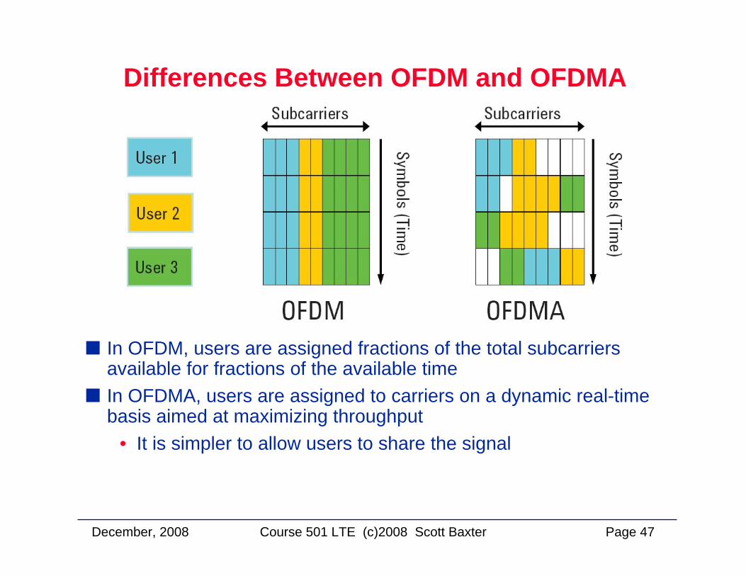
Differences Between OFDM and OFDMA
In OFDM, users are assigned fractions of the total subcarriers available for fractions of the available timeIn OFDMA, users are assigned to carriers on a dynamic real-time basis aimed at maximizing throughput
• It is simpler to allow users to share the signal
December, 2008 Page 48Course 501 LTE (c)2008 Scott Baxter
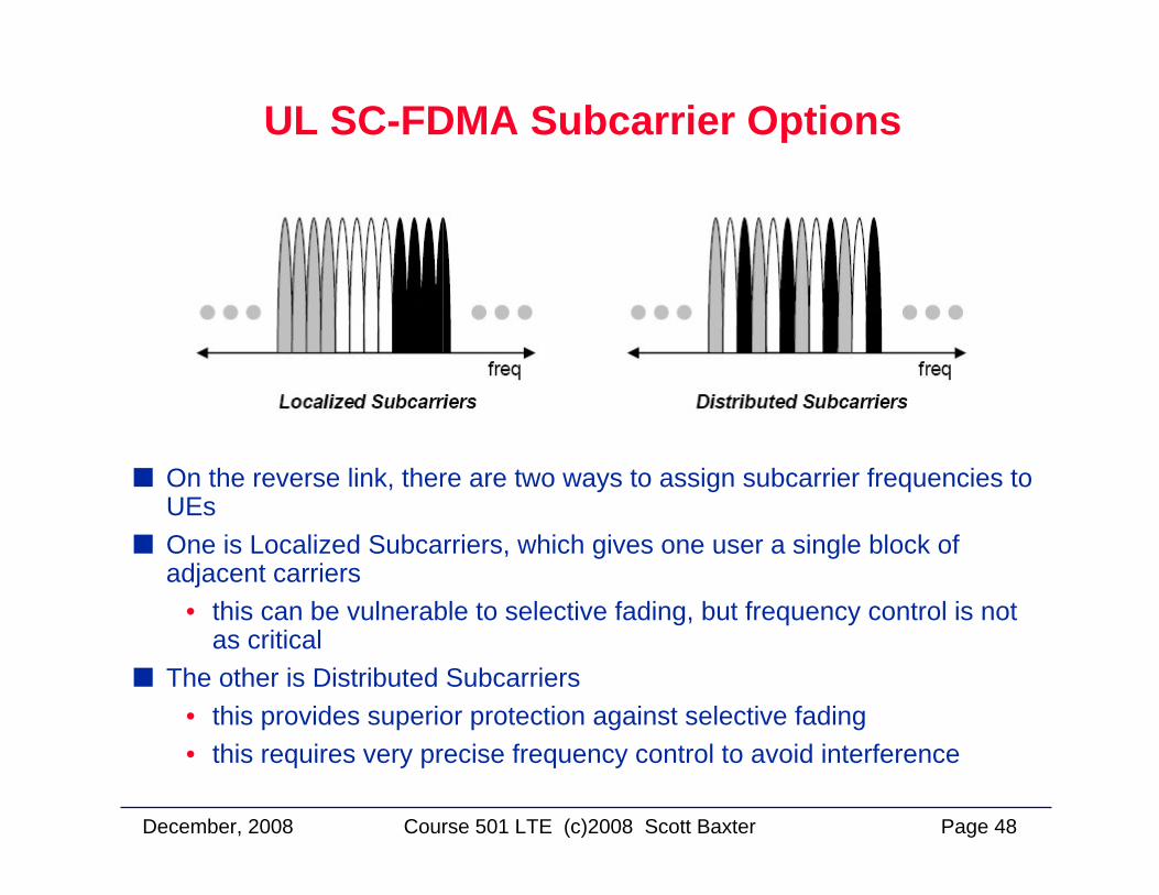
UL SC-FDMA Subcarrier Options
On the reverse link, there are two ways to assign subcarrier frequencies to UEsOne is Localized Subcarriers, which gives one user a single block of adjacent carriers
• this can be vulnerable to selective fading, but frequency control is not as critical
The other is Distributed Subcarriers• this provides superior protection against selective fading• this requires very precise frequency control to avoid interference
December, 2008 Page 49Course 501 LTE (c)2008 Scott Baxter
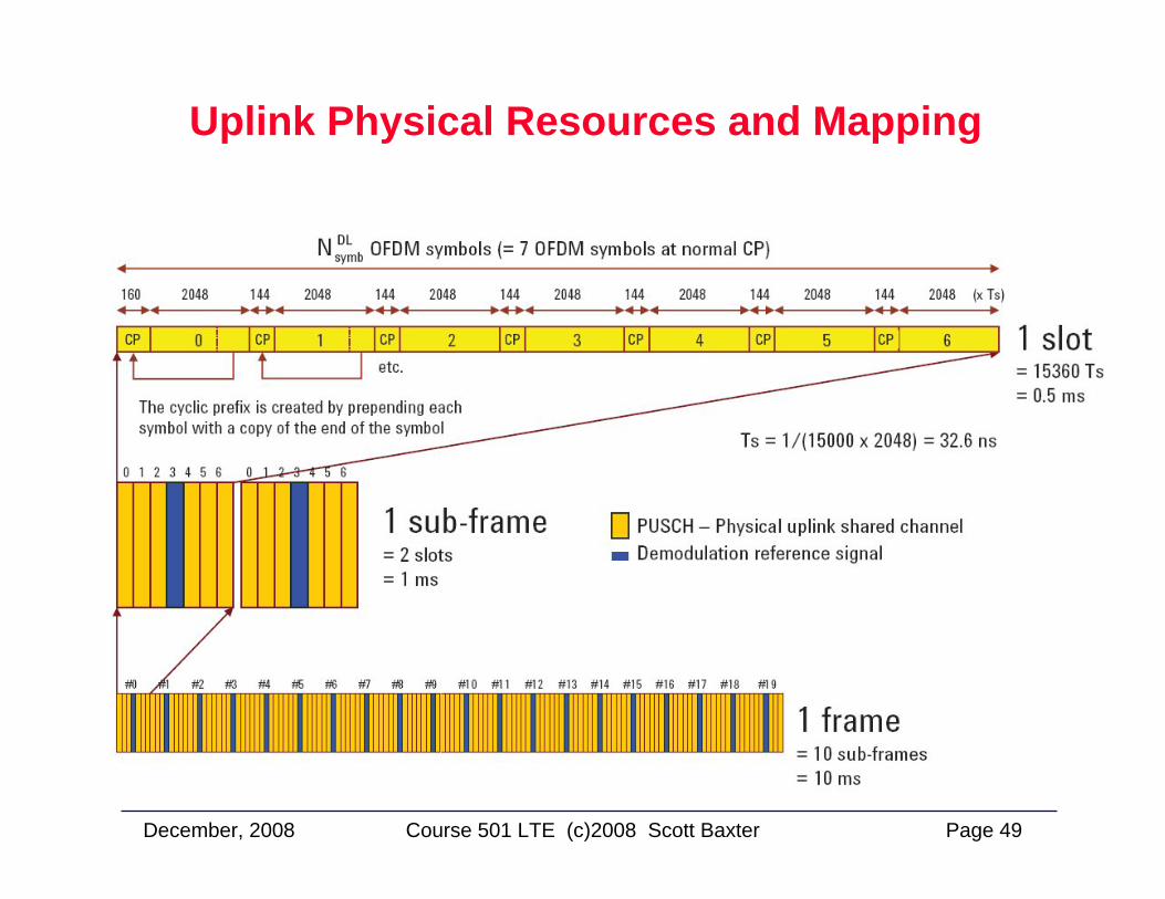
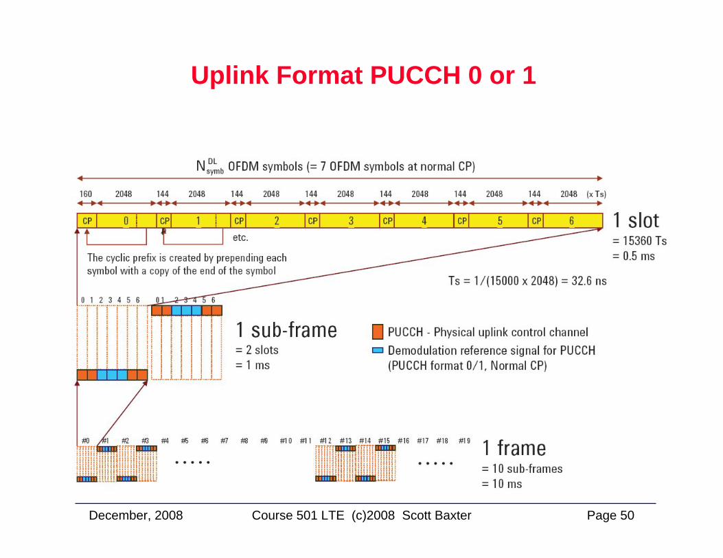
Uplink Physical Resources and Mapping
December, 2008 Page 50Course 501 LTE (c)2008 Scott Baxter
Uplink Format PUCCH 0 or 1
December, 2008 Page 51Course 501 LTE (c)2008 Scott Baxter
LTE Network Architecture:System Architecture Evolution (SAE)
LTE Network Architecture:System Architecture Evolution (SAE)
December, 2008 Page 52Course 501 LTE (c)2008 Scott Baxter
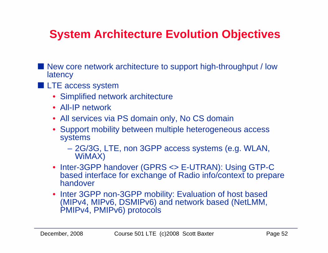
System Architecture Evolution Objectives
New core network architecture to support high-throughput / low latencyLTE access system
• Simplified network architecture• All-IP network• All services via PS domain only, No CS domain• Support mobility between multiple heterogeneous access
systems– 2G/3G, LTE, non 3GPP access systems (e.g. WLAN,
WiMAX)• Inter-3GPP handover (GPRS <> E-UTRAN): Using GTP-C
based interface for exchange of Radio info/context to prepare handover
• Inter 3GPP non-3GPP mobility: Evaluation of host based (MIPv4, MIPv6, DSMIPv6) and network based (NetLMM, PMIPv4, PMIPv6) protocols
December, 2008 Page 53Course 501 LTE (c)2008 Scott Baxter
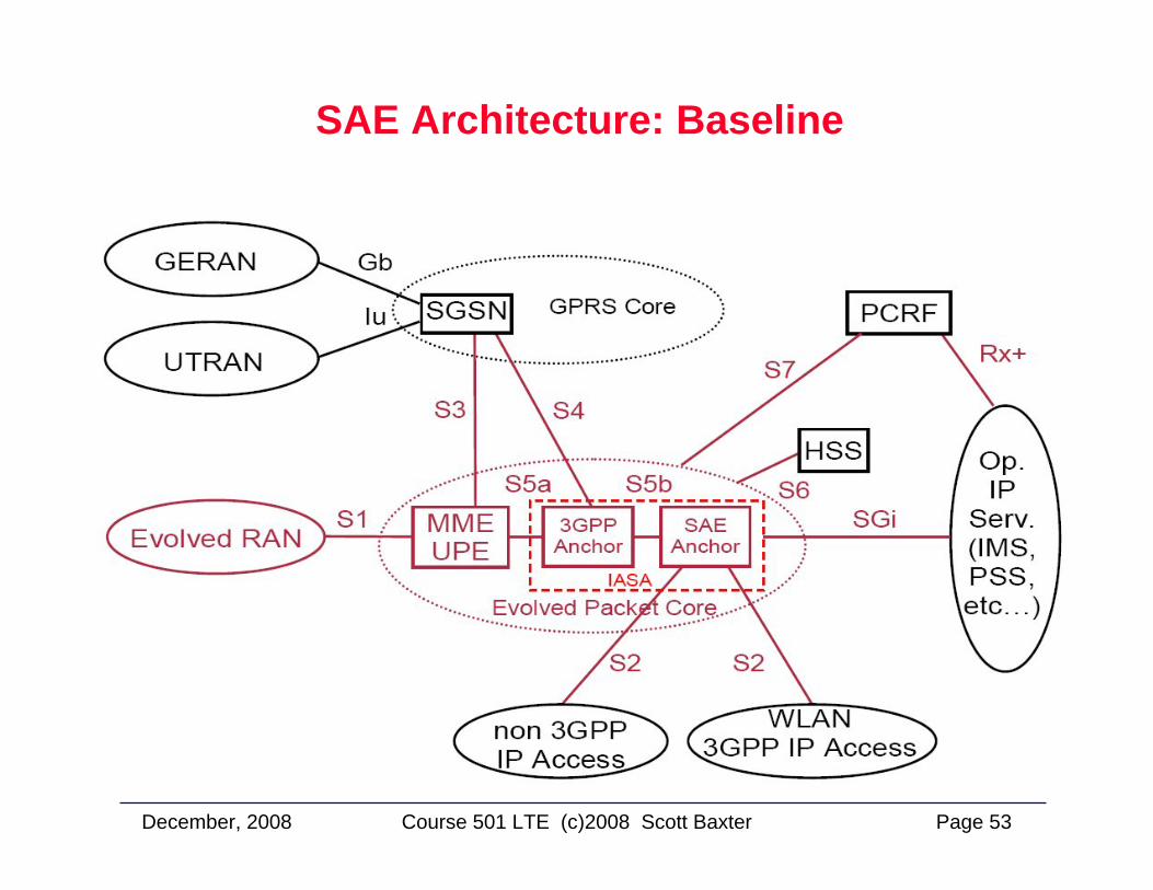
SAE Architecture: Baseline
December, 2008 Page 54Course 501 LTE (c)2008 Scott Baxter
SAE Architecture Interfaces (1)
S1-U S1 Interface User PlaneS1-U reference point (LTE SAE) Reference point between EUTRAN and SGW for the per-bearer
user plane tunneling and inter-eNB path switching during handover. The transport protocol over this interface is GPRS Tunneling Protocol-User plane (GTP-U)
S2a interface (LTE SAE) It provides the user plane with related control and mobility support between trusted non-3GPP IP access and the Gateway. S2a is based on Proxy Mobile IP. To enable access via trusted non-3GPP IP accesses that do not support PMIP, S2a also supports Client Mobile IPv4 FA mode
S2b interface (LTE SAE) Provides the user plane with related control and mobility support between evolved Packet Data Gateway (ePDG) and the PDN GW. It is based on Proxy Mobile IP.
S2c interface(LTE SAE) Provides the user plane with related control and mobility support between UE and the PDN GW. This reference point is implemented over trusted and/or untrusted non-3GPP Access and/or 3GPP access. This protocol is based on Client Mobile IP co-located mode
S3 interface (LTE SAE) The interface between SGSN and MME and it enables user and bearer information exchange for inter 3GPP access network mobility in idle and/or active state. It is based on Gn reference point as defined between SGSNs
S4 interface (LTE SAE) Provides the user plane with related control and mobility support between SGSN and the SGW and is based on Gn reference point as defined between SGSN and GGSN.
December, 2008 Page 55Course 501 LTE (c)2008 Scott Baxter
SAE Architecture Interfaces (2)
S5 interface (LTE SAE) Provides user plane tunneling and tunnel management between SGW and PDN GW. It is used for SGW relocation due to UE mobility and if the SGW needs to connect to a non-collocated PDN GW for the required PDN connectivity. Two variants of this interface are being standardized depending on the protocol used, namely, GTP and the IETF based Proxy Mobile IP solution
S5a interface (LTE SAE) Provides the user plane with related control and mobility support between MME/UPE and 3GPP anchor. It is FFS whether a standardized S5a exists or whether MME/UPE and 3GPP anchor are combined into one entity.
S5b interface (LTE SAE) Provides the user plane with related control and mobility support between 3GPP anchor and SAE anchor. It is FFS whether a standardized S5b exists or whether 3GPP anchor and SAE anchor are combined into one entity.
S6 interface (LTE SAE) Enables transfer of subscription and authentication data for authenticating/authorizing user access to the evolved system (AAA interface).
S6a interface (LTE SAE) Enables transfer of subscription and authentication data for authenticating/authorizing user access to the evolved system (AAA interface) between MME and HSS
S7 interface (LTE SAE) Provides transfer of (QoS) policy and charging rules from Policy and Charging Rules Function (PCRF) to Policy and Charging Enforcement Function (PCEF) Rules Function (PCRF) to Policy and Charging Enforcement Function (PCEF) in the PDN GW. This interface is based on the Gx interface
December, 2008 Page 56Course 501 LTE (c)2008 Scott Baxter
LTE SAE Network Element Functions
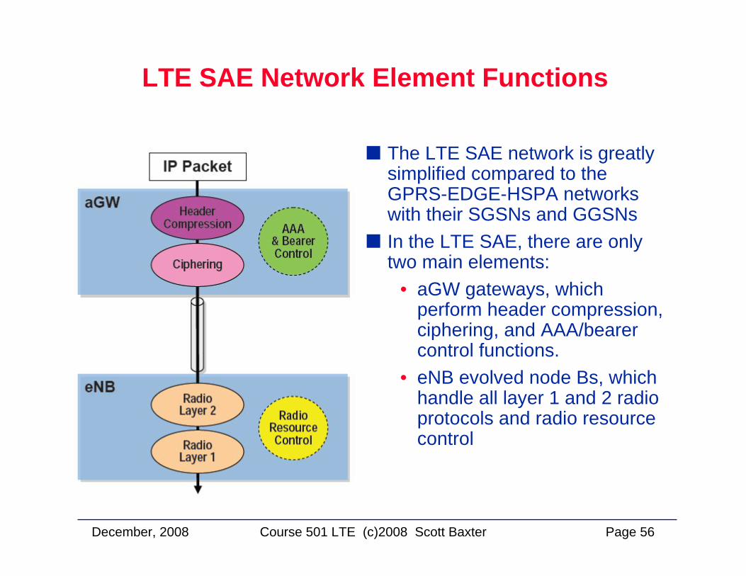
The LTE SAE network is greatly simplified compared to the GPRS-EDGE-HSPA networks with their SGSNs and GGSNsIn the LTE SAE, there are only two main elements:
• aGW gateways, which perform header compression, ciphering, and AAA/bearer control functions.
• eNB evolved node Bs, which handle all layer 1 and 2 radio protocols and radio resource control
December, 2008 Page 57Course 501 LTE (c)2008 Scott Baxter
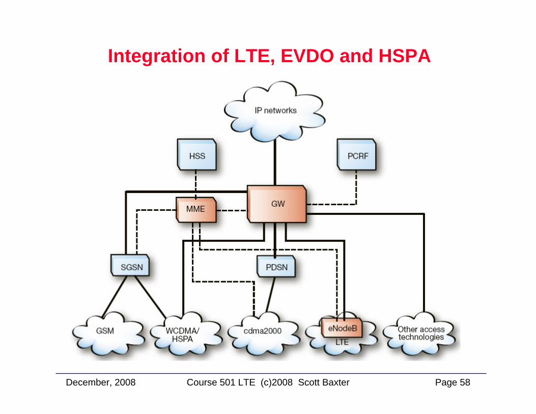
UMTS HSPA vs LTE-SAE Network Architectures
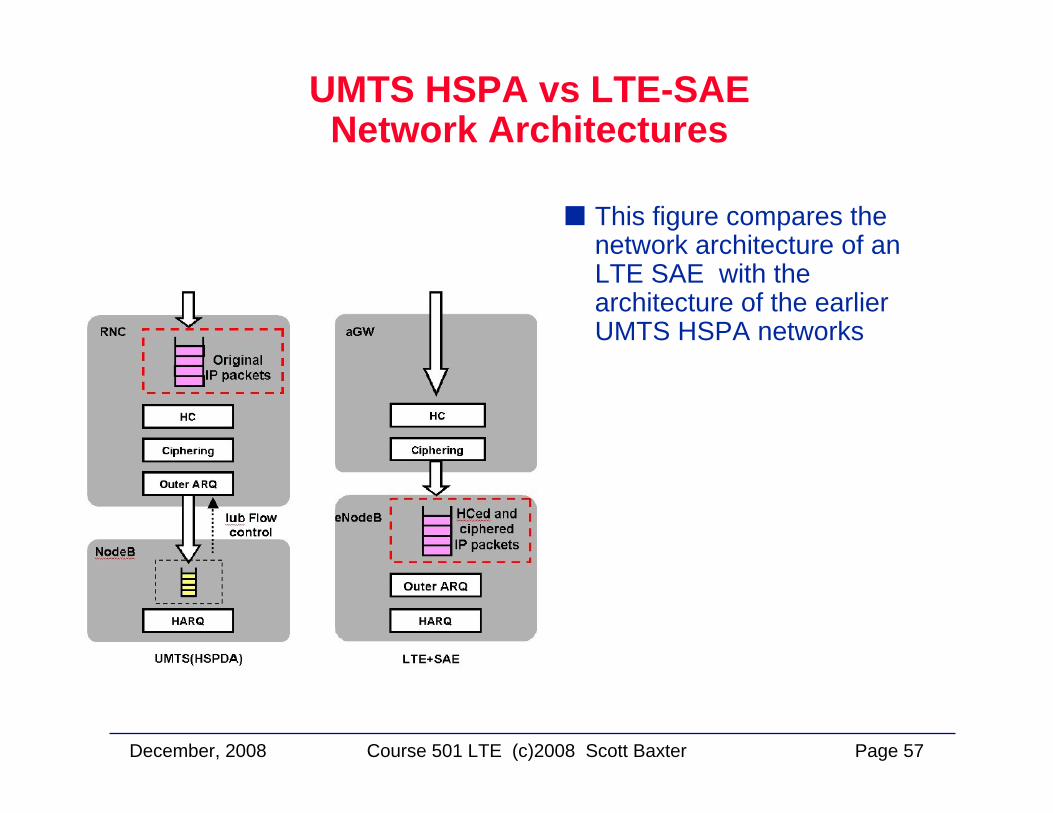
This figure compares the network architecture of an LTE SAE with the architecture of the earlier UMTS HSPA networks
December, 2008 Page 58Course 501 LTE (c)2008 Scott Baxter
Integration of LTE, EVDO and HSPA
December, 2008 Page 59Course 501 LTE (c)2008 Scott Baxter
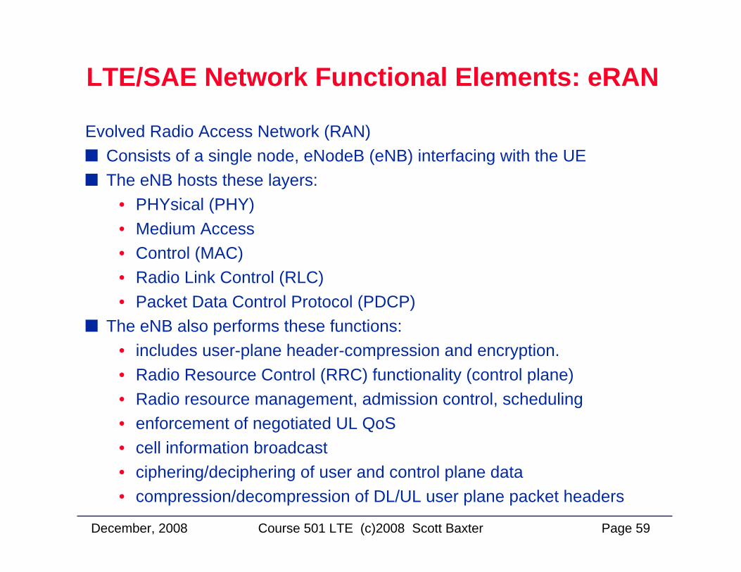
LTE/SAE Network Functional Elements: eRAN
Evolved Radio Access Network (RAN)Consists of a single node, eNodeB (eNB) interfacing with the UEThe eNB hosts these layers:
• PHYsical (PHY) • Medium Access• Control (MAC)• Radio Link Control (RLC)• Packet Data Control Protocol (PDCP)
The eNB also performs these functions:• includes user-plane header-compression and encryption. • Radio Resource Control (RRC) functionality (control plane)• Radio resource management, admission control, scheduling• enforcement of negotiated UL QoS • cell information broadcast • ciphering/deciphering of user and control plane data• compression/decompression of DL/UL user plane packet headers
December, 2008 Page 60Course 501 LTE (c)2008 Scott Baxter
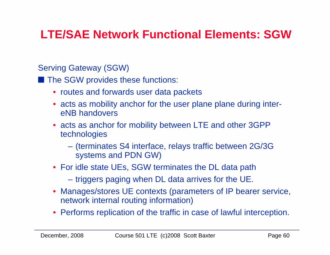
LTE/SAE Network Functional Elements: SGW
Serving Gateway (SGW)The SGW provides these functions:
• routes and forwards user data packets• acts as mobility anchor for the user plane plane during inter-
eNB handovers • acts as anchor for mobility between LTE and other 3GPP
technologies – (terminates S4 interface, relays traffic between 2G/3G
systems and PDN GW)• For idle state UEs, SGW terminates the DL data path
– triggers paging when DL data arrives for the UE. • Manages/stores UE contexts (parameters of IP bearer service,
network internal routing information)• Performs replication of the traffic in case of lawful interception.
December, 2008 Page 61Course 501 LTE (c)2008 Scott Baxter
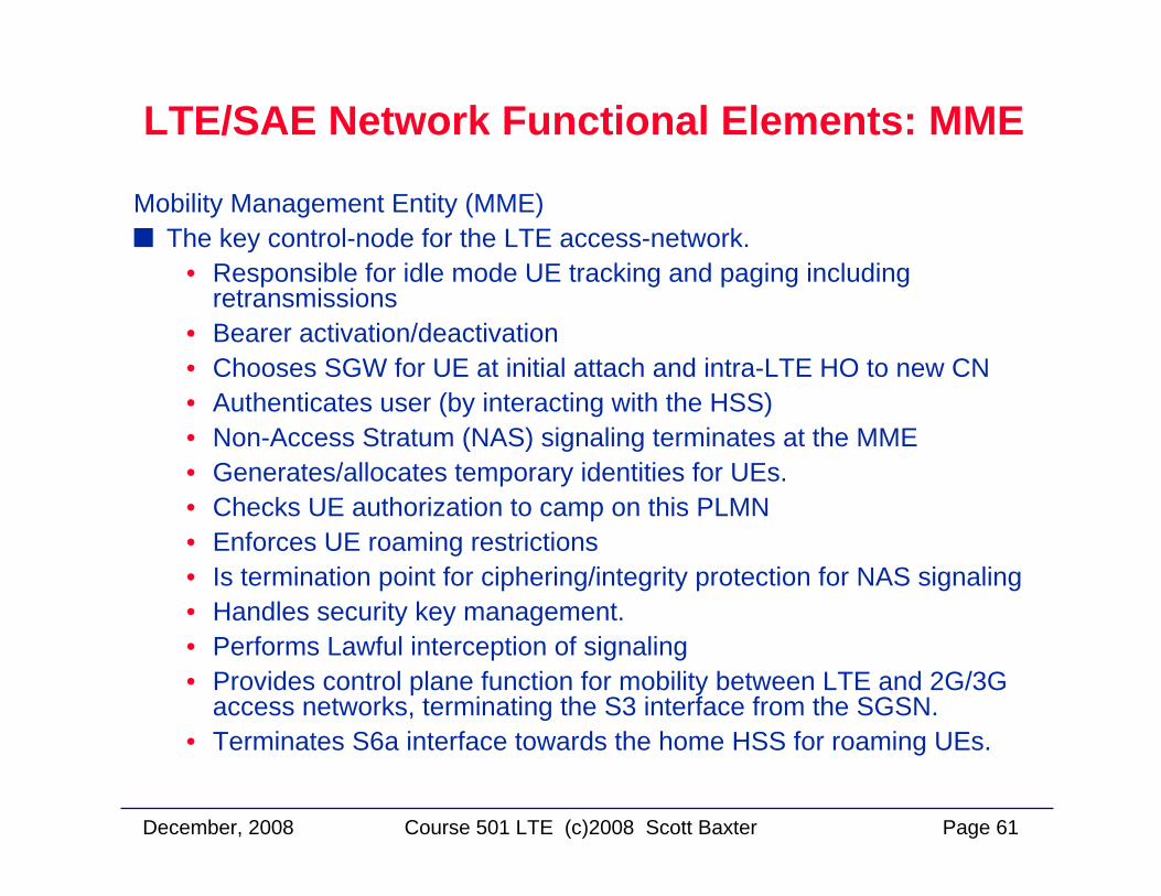
LTE/SAE Network Functional Elements: MME
Mobility Management Entity (MME)The key control-node for the LTE access-network.
• Responsible for idle mode UE tracking and paging including retransmissions
• Bearer activation/deactivation • Chooses SGW for UE at initial attach and intra-LTE HO to new CN • Authenticates user (by interacting with the HSS) • Non-Access Stratum (NAS) signaling terminates at the MME • Generates/allocates temporary identities for UEs. • Checks UE authorization to camp on this PLMN• Enforces UE roaming restrictions • Is termination point for ciphering/integrity protection for NAS signaling• Handles security key management. • Performs Lawful interception of signaling• Provides control plane function for mobility between LTE and 2G/3G
access networks, terminating the S3 interface from the SGSN. • Terminates S6a interface towards the home HSS for roaming UEs.
December, 2008 Page 62Course 501 LTE (c)2008 Scott Baxter
LTE/SAE Network Functional Elements: PDN GW
Packet Data Network Gateway (PDN GW)PDN GW roles and functions:
• Provides UE connectivity to external packet data networks as point of exit and entry of traffic for the UE
• Supports UE simultaneous connectivity with more than one PDN GW for accessing multiple PDNs
• Performs policy enforcement • Packet filtering for each user• Charging support • Lawful Interception and packet screening• Acts as mobility anchor between 3GPP and non-3GPP
technologies such as WiMAX, 3GPP2 (CDMA 1X and EvDO).
December, 2008 Page 63Course 501 LTE (c)2008 Scott Baxter
LTE SAE Network Key Features (1)
EPS to EPCKey feature of the EPS is the separation of the network entity that performs control-plane functionality (MME) from the network entity that performs bearer-plane functionality (SGW) with a well-defined open interface between them (S11). Since E-UTRAN will provide higher bandwidths to enable new services as well as to improve existing ones, separation of MME from SGW implies that SGW can be based on a platform optimized for high bandwidth packet processing, where as the MME is based on a platform optimized for signaling transactions.This enables selection of more cost-effective platforms for, as well as independent scaling of, each of these two elements. Service providers can also choose optimized topological locations of SGWs within the network independent of the locations of MMEs in order to optimize bandwidth reduce latencies and avoid concentrated points of failure.
December, 2008 Page 64Course 501 LTE (c)2008 Scott Baxter
LTE SAE Network Key Features (2)
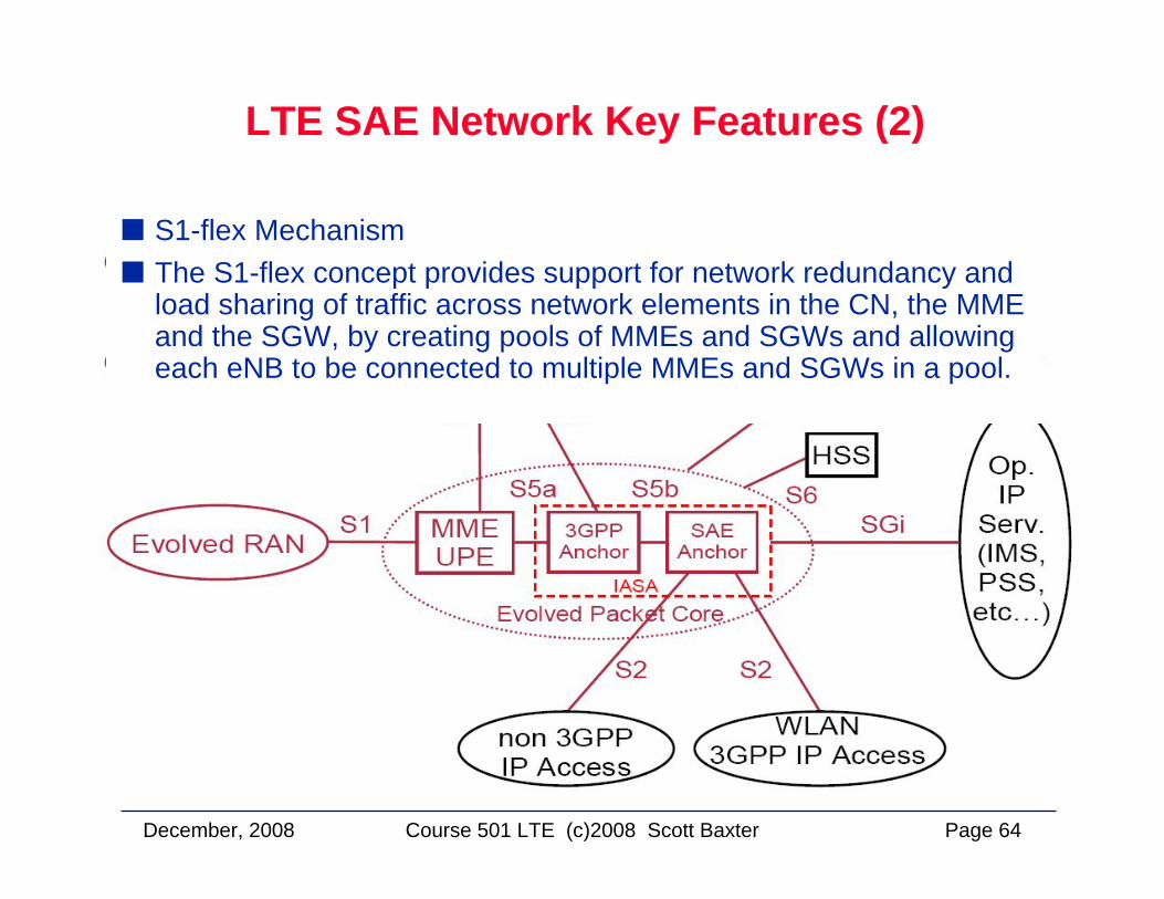
S1-flex MechanismThe S1-flex concept provides support for network redundancy and load sharing of traffic across network elements in the CN, the MME and the SGW, by creating pools of MMEs and SGWs and allowing each eNB to be connected to multiple MMEs and SGWs in a pool.
December, 2008 Page 65Course 501 LTE (c)2008 Scott Baxter
LTE Progress Milestones
2006 at ITU trade fair in Hong Kong, by Siemens:• First demonstration of LTE HDTV streaming (>30 Mbit/s)• video supervision • Mobile IP-based handover between the LTE radio
demonstrator and the commercially available HSDPA radio system
Researchers at Nokia Siemens Networks/Heinrich Hertz Institute demonstrated LTE with 100 Mbit/s Uplink transfer speedsFebruary 2007 at 3G World Congress - Nortel publicly demonstrated the first complete LTE air interface implementationincluding OFDM-MIMO, SC-FDMA and multi-user MIMO uplinkVerizon Wireless plans to begin LTE trials in 2008.
December, 2008 Page 66Course 501 LTE (c)2008 Scott Baxter
WiMAX SpecificsWiMAX Specifics
December, 2008 Page 67Course 501 LTE (c)2008 Scott Baxter
WiMax
WiMAX (Worldwide Interoperability for Microwave Access) is based on the IEEE 802.16 standard
• Provides MAN (Metropolitan Area Network) broadband connectivity
• also known as the IEEE WirelessMAN air interface.WiMAX-based systems can have ranges up to 30 miles. The 802.16d standard of extending 802.16 supports three physicallayers (PHYs).
• The mandatory PHY mode is 256-point FFT Orthogonal Frequency Division Multiplexing (OFDM).
• The other two PHY modes are Single Carrier (SC) and • 2048 OFDMA mode • For interest, the corresponding European standard—the ETSI
HiperMAN standard—defines a single PHY mode identical to the 256 OFDM modes in the 802.16d standard.
December, 2008 Page 68Course 501 LTE (c)2008 Scott Baxter
WiMax Technical Details
WiMAX can be used over many different frequency ranges • 10GHz to 66GHz under 802.16. • 802.16a covers 2GHz-to-11GHz • WiMAX range can reach 30 miles with a typical cell radius of
4–6 miles.WiMAX's channel sizes range from 1.5 to 20MHz, offer corresponding data rates
• Rates from 1.5Mbps to 70Mbps on a single channel • one carrier can support thousands of users
WiMAX supports ATM, IPv4, IPv6, Ethernet, and VLAN services • facilitates many service possibilities in voice and data
WiMAX could be used as a backhaul technology to connect 802.11 wireless LANs and commercial hotspots with the InternetWiMax systems would be deployed much like cellular systems.
December, 2008 Page 69Course 501 LTE (c)2008 Scott Baxter
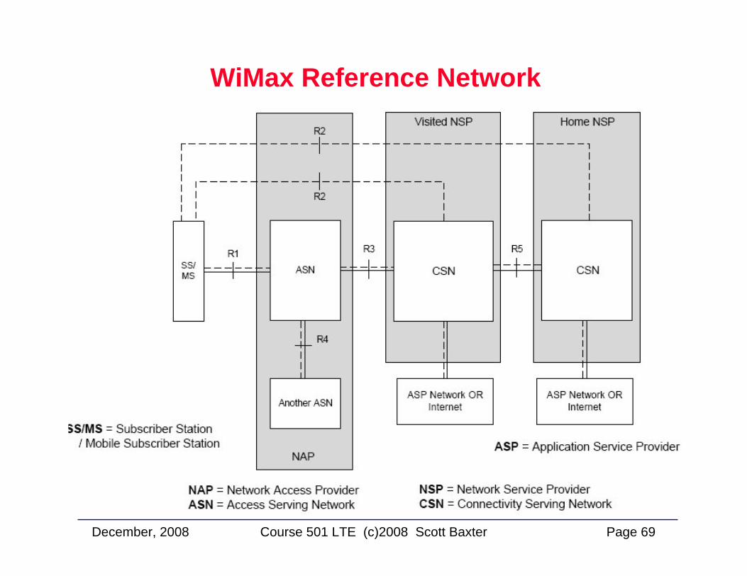
WiMax Reference Network