Embed Size (px)
Citation preview

5100 Quick Start Manual – 5100-601-340
5100 Digital Indicator
Quick Start Manual For use with Software Versions 3.0 and above
5100-601-340

5100 Quick Start Manual – 5100-601-340
Introduction The Ranger 5100 is a precision industrial digital indicator using the latest technology to ensure fast and accurate weight readings.
FEATURES The indicator is fitted with an alpha numeric 20mm LCD backlit display that can be read in all lighting conditions as well as
- Alpha/Numeric LCD with LED backlighting. - Programmable special functions key. - Full numeric keypad with alpha entry. - Real Time Clock and RAM for storing Zero,Tare and Total settings etc. - Support for Setpoint or Combo Accessory Cards. - Ranger Smart Options:
- Serial (0202) - Modbus Protocol (0213) needs (0202) - Intelligent Batching for up to 6 materials(0217) - Intelligent Batching Extension to 20 Materials(0222)
ACCESSORIES - 0107 12VDC 1A Plug Pack Power Supply for use with DC models. - 0212 Combo Accessory Card. 2 open collector outputs, 1 input and Voltage
or Current analogue outputs. - 0204 Setpoint Accessory Card: 4 open collector outputs and 4 inputs. - 0081 RS232-20mA Loop Converter. - 0215 DIN rail Relay Module. - 0221 Viewer Software - 0301 Panel Mount Clamps / 0302 Swivel Mount Clamps. - 0303 30 degree Fixed Desk Mount Bracket. - 0304 Stainless Steel IP65 Housing - 0305 Stainless Steel Desk Bracket (requires 0302) - 0306 Stainless Steel Wall Bracket (requires 0302) - 0119 NAIS PLC 8 input 6 output - 0120 NAIS 8 input 8 output expansion unit - 0118 NAIS 240VAC to 24VDC DIN rail Power Supply
MANUALS The Quick-Start Manual is part of a set of manuals including the Communications, Modbus and Reference manuals. The Quick Start Manual is intended for use by installers familiar with this product. At all times refer to the Reference Manual for a detailed description of any particular setting or option. Copies of all manuals and Viewer software are available free of charge from the Rinstrum web site at www.rinstrum.com.

5100 Quick Start Manual – 5100-601-340
Installation The following steps are required to install the 5100 indicator. (1) First inspect the unit to ensure that it is in good condition, and that the required
mounting options and connectors are available. (2) Use the connection diagrams to wire up the loadcell, power and serial cables as
required. Connectors for all of these cables are supplied with the indicator. (3) Connect Power to the unit to start the instrument. (4) Follow the instructions in INSTRUMENT SETUP to configure and calibrate the
instrument. (5) Enter passcodes for SAFE and FULL setup to protect the settings from tampering
and record these in a safe place for future reference.
SPECIAL FUNCTIONS The special function key on the 5100 is set-up as a blank key. If any of the special functions are to be used on the indicator it is important that the matching function key sticker is applied to the keypad. To install this sticker, make sure that the keypad is clean and dry. If in doubt, the keypad can be cleaned with a soft cloth dipped in Methylated Spirits. Alternatively use warm soapy water but make sure the keypad is thoroughly dry before proceeding. RANGER SMART SOFTWARE OPTIONS To enable any of the RANGER SMART Software options you need to enter a license code. The license codes are unique to each option and to each instrument and may be factory installed or installed in the field. To check to see what options are fitted or to install another option:
q Press the SET and FUNCTION keys together for 2 seconds. q The 5100 will display the installed options and prompt for a new license
code. q Use the numeric keypad to enter the license code. q Press the Function key when done. q If successful the new option will be displayed, otherwise the 5100 will
beep. q Press the Function Key to enter a code of 0 and return to normal
operation. Software Option Display Features
0202 Serial Communications
"Serial" Needed to enable the use of Ser1 or Ser2 for printing, remote display driving, networking etc.
0217 Intelligent Setpointing
"Setpnt" Full batching capabilities for up to 6 materials.
0213 Modbus Communications
"Modbus" Enables the use of the Modbus ASCII network protocol. Requires the Serial Communications option as well.
0222 Extended Setpointing
"Full.SP" Extends batching capabilities to enable up to 20 different materials along with the Total Setpoint batching option. This option requires 0217 as well. This option is also required along with the 0202 to drive the PLC based output modules.
5100 Quick Start Manual – 5100-601-340
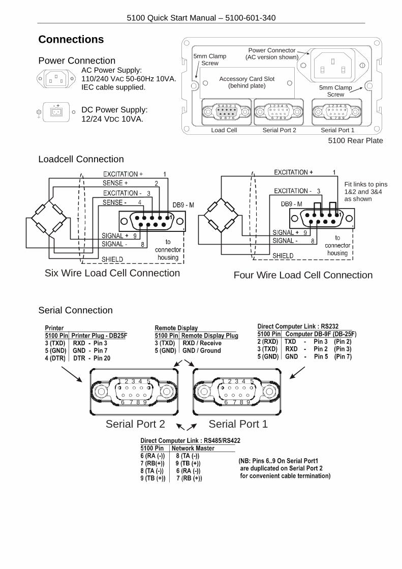
Connections Power Connection
AC Power Supply: 110/240 VAC 50-60Hz 10VA. IEC cable supplied.
DC Power Supply: 12/24 VDC 10VA.
Loadcell Connection
Serial Connection
Accessory Card Slot(behind plate)
Power Connector(AC version shown)
Serial Port 1Serial Port 2Load Cell
5100 Rear Plate
5mm ClampScrew
5mm ClampScrew
5 4 3 2 1
9 8 7 6
1 2 3 4 5
6 7 8 9
1 2 3 4 5
6 7 8 9
Six Wire Load Cell Connection
+-
Serial Port 1Serial Port 2
1 2 3 4 5
6 7 8 9
1 2 3 4 5
6 7 8 9
Fit links to pins1&2 and 3&4as shown
Four Wire Load Cell Connection
5100 Quick Start Manual – 5100-601-340
+ -SET
RECIPE
+ -SET
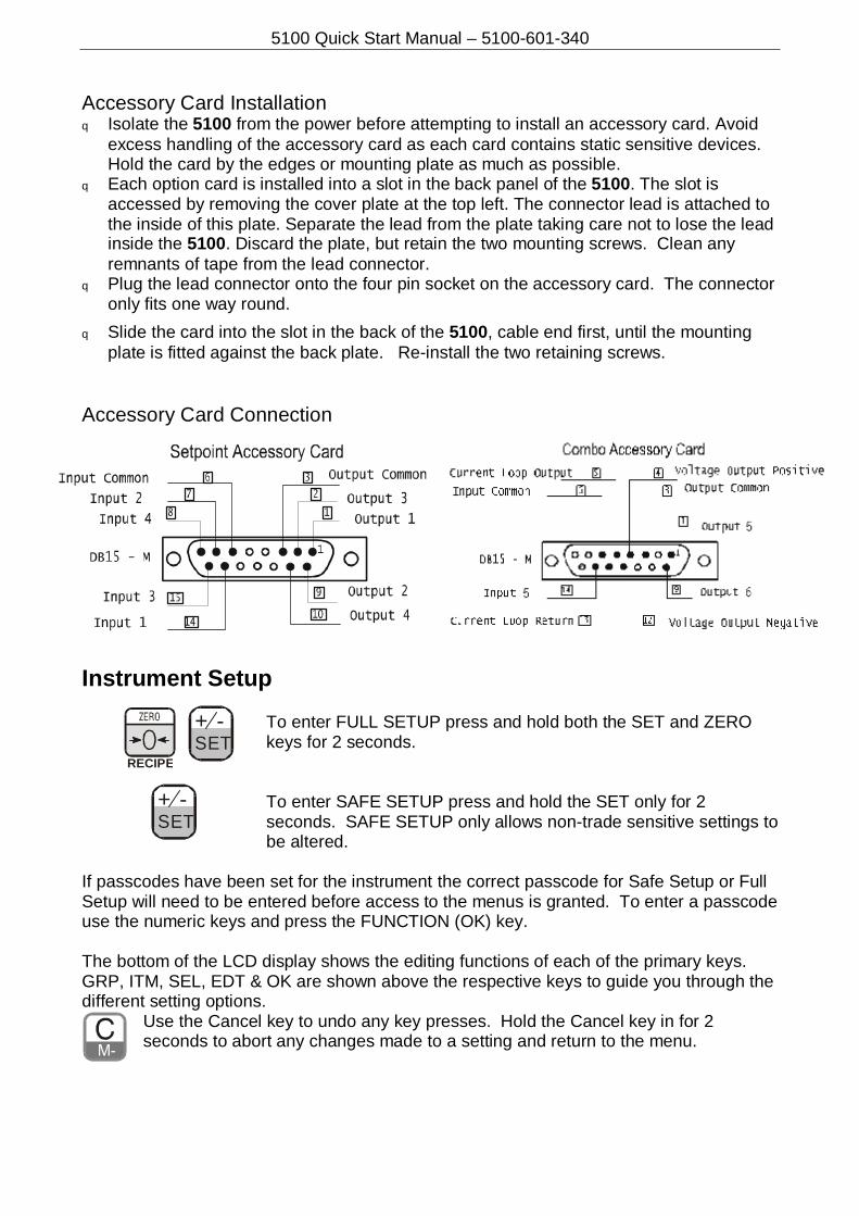
Accessory Card Installation q Isolate the 5100 from the power before attempting to install an accessory card. Avoid
excess handling of the accessory card as each card contains static sensitive devices. Hold the card by the edges or mounting plate as much as possible.
q Each option card is installed into a slot in the back panel of the 5100. The slot is accessed by removing the cover plate at the top left. The connector lead is attached to the inside of this plate. Separate the lead from the plate taking care not to lose the lead inside the 5100. Discard the plate, but retain the two mounting screws. Clean any remnants of tape from the lead connector.
q Plug the lead connector onto the four pin socket on the accessory card. The connector only fits one way round.
q Slide the card into the slot in the back of the 5100, cable end first, until the mounting plate is fitted against the back plate. Re-install the two retaining screws.
Accessory Card Connection Instrument Setup
To enter FULL SETUP press and hold both the SET and ZERO keys for 2 seconds.
To enter SAFE SETUP press and hold the SET only for 2 seconds. SAFE SETUP only allows non-trade sensitive settings to be altered.
If passcodes have been set for the instrument the correct passcode for Safe Setup or Full Setup will need to be entered before access to the menus is granted. To enter a passcode use the numeric keys and press the FUNCTION (OK) key. The bottom of the LCD display shows the editing functions of each of the primary keys. GRP, ITM, SEL, EDT & OK are shown above the respective keys to guide you through the different setting options.
Use the Cancel key to undo any key presses. Hold the Cancel key in for 2 seconds to abort any changes made to a setting and return to the menu.

5100 Quick Start Manual – Rev 3.3
GROUP
ITEM
SELECT
EDIT
OK A press of the keys above will select and step through the functions in the columns below them
BUILD TYPE Scale ranging selection SINGLE (single range) DUAL r (dual range) DUAL I (dual interval) DirEct (direct mV/V)
Save
DP Decimal point position 000000, 00000.0, 0000.00, 000.000, 00.0000, 0.00000
Save
CAP1 Capacity of first range [use keyboard] Save E1 Resolution of first range 1, 2, 5, 10, 20, 50, 100 [use keyboard] Save CAP2 Capacity of second range [use keyboard] Save E2 Resolution of second range 1, 2, 5, 10, 20, 50, 100 [use keyboard] Save UNITS Units of measure None, g (grams) kg (kilograms) lb (pounds)
t (tonnes/tons) Save
OPTION USE Industrial or trade use IndUST (+ & - weighing) or TRAdE (trade ) Save
FILTER Digital Filtering/Averaging 1 (number of A/D readings to be averaged ) or 2, 3, 4, 5, 6, 7, 8, 9, 10, 25, 50, 75, 100, 200
Save
JITTER Display filter OFF (stabilizes minor weight changes) FinE, COARSE
Save
MOTION Motion detection setting NONE or 0.5 divs over 1.0 second in steps up to 5 divs per 0.2 second
Save
AUTO.Z Auto zero on power up OFF or ON Save Z.TRAC Zero tracking setting NONE or
0.5 divs over 1.0 second in steps up to 5 divs per 0.2 second (affected by zero band)
Save
Z.RANGE Zero key range in percentages 02-02, 01-03, 20-20, 100.100 Save Z.BAND Zero band width in divisions [use keyboard] (also limits zero tracking range) Save
CAL ZERO Current weight is displayed Zero in progress [press tare key to exit]
SPAN Current weight is displayed Key in capacity [then press the function key] Span in progress [press tare key to exit]
Ed.LIN Edit linearisation points [use keyboard to enter correct weight] Save Clr.LIN Clear linearisation points [use keyboard to select each point] Save FAC.CAL Restore indicator to default
factory configuration Cont n (continue –No?) Cont Y (Yes) WARNING! All current setup will be lost – excluding zero & span
Save
SPEC PASSCD Set full access passcode [use keyboard] Save
Set safe access passcode [use keyboard] Save Set operator access passcode [use keyboard] Set operator access level 0, 1, 2, 3, 4, 5, 6, 7 (see reference manual) Save
To enter setup: press both the set and zero keys for 2 seconds.
Each press of the C/m- key will go back one step in the menus. At the bottom of the LCD display are prompts for key functions (group, item, select, edit, OK, etc).
5100 Quick Start Manual – Rev 3.3
GROUP
ITEM
SELECT
EDIT
OK A press of the keys above will select and step through the functions in the columns below them
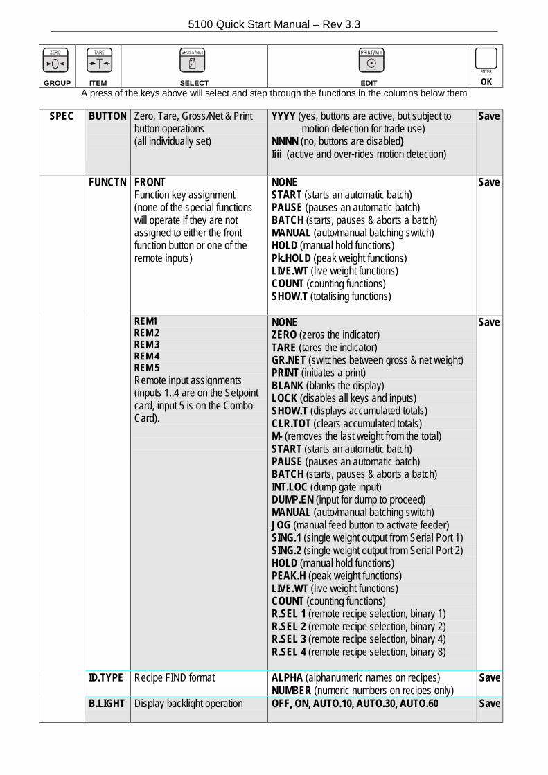
SPEC BUTTON
Zero, Tare, Gross/Net & Print button operations (all individually set)
YYYY (yes, buttons are active, but subject to motion detection for trade use) NNNN (no, buttons are disabled) Iiii (active and over-rides motion detection)
Save
FUNCTN FRONT Function key assignment (none of the special functions will operate if they are not assigned to either the front function button or one of the remote inputs)
NONE START (starts an automatic batch) PAUSE (pauses an automatic batch) BATCH (starts, pauses & aborts a batch) MANUAL (auto/manual batching switch) HOLD (manual hold functions) Pk.HOLD (peak weight functions) LIVE.WT (live weight functions) COUNT (counting functions) SHOW.T (totalising functions)
Save
REM1 REM 2 REM 3 REM 4 REM 5 Remote input assignments (inputs 1..4 are on the Setpoint card, input 5 is on the Combo Card).
NONE ZERO (zeros the indicator) TARE (tares the indicator) GR.NET (switches between gross & net weight) PRINT (initiates a print) BLANK (blanks the display) LOCK (disables all keys and inputs) SHOW.T (displays accumulated totals) CLR.TOT (clears accumulated totals) M- (removes the last weight from the total) START (starts an automatic batch) PAUSE (pauses an automatic batch) BATCH (starts, pauses & aborts a batch) INT.LOC (dump gate input) DUMP.EN (input for dump to proceed) MANUAL (auto/manual batching switch) JOG (manual feed button to activate feeder) SING.1 (single weight output from Serial Port 1) SING.2 (single weight output from Serial Port 2) HOLD (manual hold functions) PEAK.H (peak weight functions) LIVE.WT (live weight functions) COUNT (counting functions) R.SEL 1 (remote recipe selection, binary 1) R.SEL 2 (remote recipe selection, binary 2) R.SEL 3 (remote recipe selection, binary 4) R.SEL 4 (remote recipe selection, binary 8)
Save
ID.TYPE Recipe FIND format ALPHA (alphanumeric names on recipes) NUMBER (numeric numbers on recipes only)
Save
B.LIGHT Display backlight operation OFF, ON, AUTO.10, AUTO.30, AUTO.60
Save
5100 Quick Start Manual – Rev 3.3
GROUP
ITEM
SELECT
EDIT
OK A press of the keys above will select and step through the functions in the columns below them
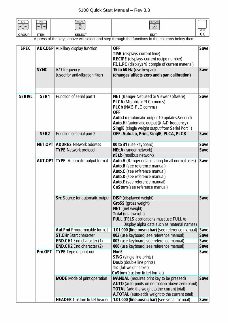
SPEC AUX.DSP Auxillary display function OFF TIME (displays current time) RECIPE (displays current recipe number) FILL.PC (displays % comple of current material)
Save
SYNC A/D frequency (used for anti-vibration filter)
15 to 60 Hz (use keypad) (changes affects zero and span calibration)
Save
SERIAL SER1 Function of serial port 1 NET (Ranger-Net used or Viewer software)
PLCA (Mitsubishi PLC comms) PLCb (NAIS PLC comms) OFF Auto.Lo (automatic output 10 updates/second) Auto.Hi (automatic output @ A/D frequency) SinglE (single weight output from Serial Port 1)
Save
SER2 Function of serial port 2 OFF, Auto.Lo, Print, SinglE, PLCA, PLCB
Save
NET.OPT ADDRES Network address 00 to 31 (use keyboard) Save TYPE Network protocol NEt.A (ranger network)
nEt.b (modbus network) Save
AUT.OPT TYPE Automatic output format Auto.A (Ranger default string for all normal uses) Auto.B (see reference manual) Auto.C (see reference manual) Auto.D (see reference manual) Auto.E (see reference manual) CuStom (see reference manual)
Save
Src Source for automatic output DISP (displayed weight) GroSS (gross weight) NET (net weight) Total (total weight) FULL (FELS applications must use FULL to Display alpha data such as material names)
Save
Aut.Fmt Programmable format 1.01.000 (line.posn.char) (see reference manual) Save ST.CHr Start character 002 (use keyboard, see reference manual) Save END.CH1 End character (1) 003 (use keyboard, see reference manual) Save END.CH2 End character (2) 000 (use keyboard, see reference manual) Save Prn.OPT TYPE Type of print-out NonE
SING (single line prints) Doub (double line prints) Tic (full weight ticket) CuStom (custom ticket format)
Save
MODE Mode of print operation MANUAL (requires print key to be pressed) AUTO (auto-prints on no motion above zero band) TOTAL (add the weight to the current total) A.TOTAL (auto-adds weight to the current total)
Save
HEADER Custom ticket header 1.01.000 (line.posn.char) (see serial manual) Save
5100 Quick Start Manual – Rev 3.3
GROUP
ITEM
SELECT
EDIT
OK A press of the keys above will select and step through the functions in the columns below them
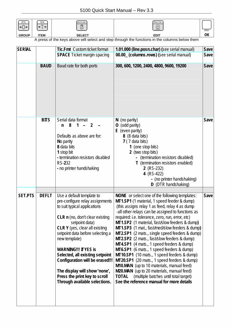
SERIAL Tic.Fmt Custom ticket format 1.01.000 (line.posn.char) (see serial manual) Save SPACE Ticket margin spacing 00.00_ (columns.rows) (see serial manual)
Save
BAUD
Baud rate for both ports 300, 600, 1200, 2400, 4800, 9600, 19200
Save
BITS
Serial data format n 8 1 – 2 – Defaults as above are for: No parity 8 data bits 1 stop bit - termination resistors disabled RS-232 - no printer handshaking
N (no parity) O (odd parity) E (even parity) 8 (8 data bits) 7 ( 7 data bits) 1 (one stop bits) 2 (two stop bits) - (termination resistors disabled) T (termination resistors enabled) 2 (RS-232) 4 (RS-422)
- (no printer handshaking) D (DTR handshaking)
Save
SET.PTS DEFLT Use a default template to
pre-configure relay assignments to suit typical applications CLR n (no, don’t clear existing setpoint data) CLR Y (yes, clear all existing setpoint data before selecting a new template) WARNING!!! If YES is Selected, all existing setpoint Configuration will be erased!!! The display will show ‘none’, Press the print key to scroll Through available selections.
NONE or select one of the following templates: MT1.SP1 (1 material, 1 speed feeder & dump) (this assigns relay 1 as feed, relay 4 as dump -all other relays can be assigned to functions as required: i.e. tolerance, zero, run, error, etc) MT1.SP2 (1 material, fast/slow feeders & dump) MT1.SP3 (1 mat., fast/med/slow feeders & dump) MT2.SP1 (2 mats., single speed feeders & dump) MT2.SP2 (2 mats., fast/slow feeders & dump) MT4.SP1 (4 mats., 1 speed feeders & dump) MT6.SP1 (6 mats., 1 speed feeders & dump) MT10.SP1 (10 mats., 1 speed feeders & dump) MT20.SP1 (20 mats., 1 speed feeders & dump) M10.MAN (up to 10 materials, manual feed) M20.MAN (up to 20 materials, manual feed) TOTAL (multiple batches until total target) See the reference manual for more details
Save
5100 Quick Start Manual – Rev 3.3
GROUP
ITEM
SELECT
EDIT
OK A press of the keys above will select and step through the functions in the columns below them
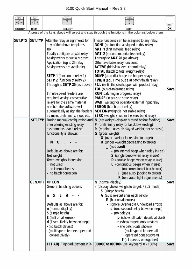
SET.PTS
SET.TYP
Alter the relay assignments for any of the above templates OR Totally configure any/all relay Assignments to suit a custom Application (up to 25 relay Assignments are available). SETP 1 (function of relay 1) SETP 2 (function of relay 2) Through to SETP 25 (as above) If multi-speed feeders are required, assign consecutive relays for the same material number. the software will automatically assign the feeders as main, preliminary, slow, etc.
These functions can be assigned to any relay: NONE (no function assigned to this relay) MAT. 1 (first material feed relay) MAT. 2 (second material feed relay) Through to MAT.20 (as above) Other available relay functions: ACTIVE (high/low level control relay) TOTAL (batch to total weight relay) DUMP (auto-discharge the hopper relay) FINISH (adj. Time pulse at batch finish relay) FILL (re-fill the silo/hopper with product relay) TOL (out-of-tolerance relay) RUN (batching in progress relay) PAUSE (in paused state relay) WAIT (waiting for operator/external input relay) ERROR (batch error relay) MOTION (weight is not stable relay) ZERO (weight is within the zero band relay)
Save
SET.TYP During manual configuration and after altering existing relay assignments, each relays functionality is shown: N O _ - - Defaults as above are for: Net weight Over –weights increasing _ not used - no internal beeps - no batch correction
N (net weight –display is tared before feeding) P (preliminary relay for fast/slow feeding) R (reading –uses displayed weight, net or gross) G (gross weight) O (over –weight increasing to target) U (under –weight decreasing to target) _ (not used) - (no internal beep when relay in use) S (single beep when relay in use) D (double beeps when relay in use) C (continuous beeps when in use) - (no correction of batch error) J (use auto- jogging to target) F (use auto-flight adjustments)
Save
GEN.OPT OPTION General batching options n S E d - - Defaults as above are for: n (normal display) S (single batch) E (halt on all errors) d (1 sec. Delay between steps) - (no batch details) - (multi-speed feeders operated consecutively)
N (normal display) r (display shows weight to target, FELS mode) S (single batch) A (auto re-start after each batch) E (halt on all errors) - (ignore Overload & Underload errors) d (one second delay between steps) - (no delays) b (show full batch details at start) t (show targets only at start) - (no batch data shown) - (multi-speed feeders all operated consecutively) F (all speeds on together)
Save
FLT.ADJ Flight adjustment in % 000000 to 000100 (use keyboard, 0 - 100%)
Save
5100 Quick Start Manual – Rev 3.3
GROUP
ITEM
SELECT
EDIT
OK A press of the keys above will select and step through the functions in the columns below them
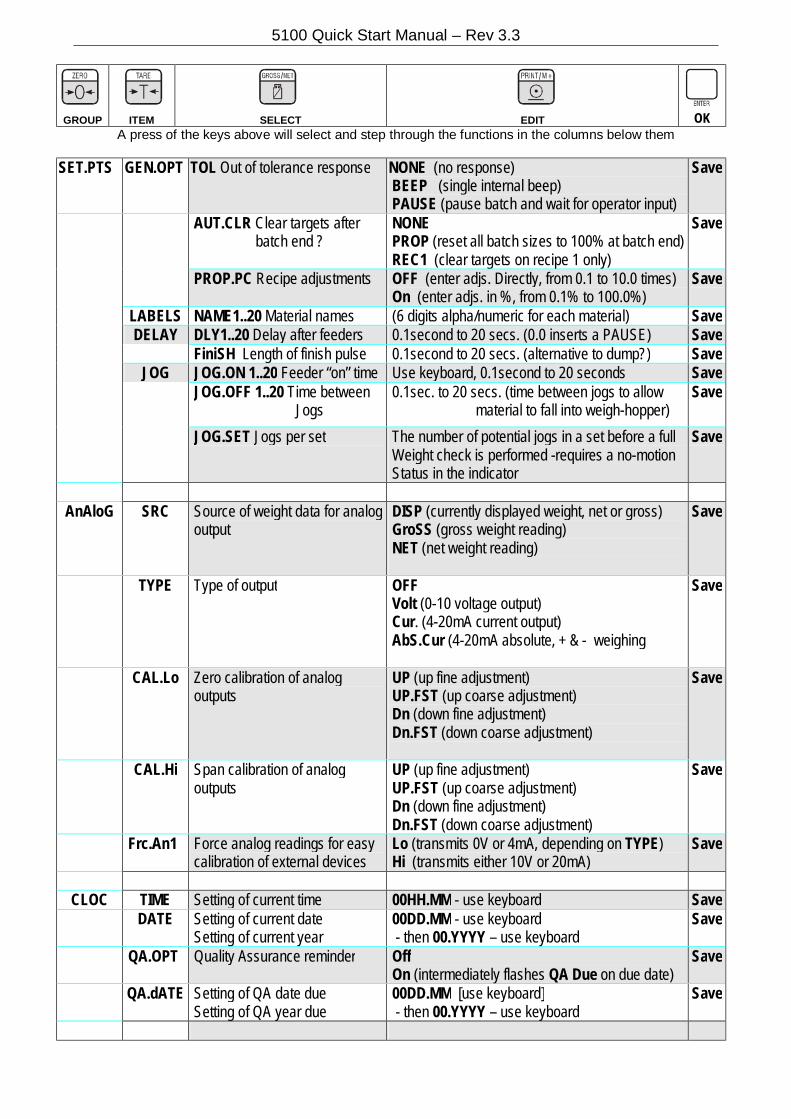
SET.PTS GEN.OPT TOL Out of tolerance response NONE (no response) BEEP (single internal beep) PAUSE (pause batch and wait for operator input)
Save
AUT.CLR Clear targets after batch end ?
NONE PROP (reset all batch sizes to 100% at batch end) REC1 (clear targets on recipe 1 only)
Save
PROP.PC Recipe adjustments OFF (enter adjs. Directly, from 0.1 to 10.0 times) On (enter adjs. in %, from 0.1% to 100.0%)
Save
LABELS NAME1..20 Material names (6 digits alpha/numeric for each material) Save DELAY DLY1..20 Delay after feeders 0.1second to 20 secs. (0.0 inserts a PAUSE) Save FiniSH Length of finish pulse 0.1second to 20 secs. (alternative to dump?) Save JOG JOG.ON 1..20 Feeder “on” time Use keyboard, 0.1second to 20 seconds Save JOG.OFF 1..20 Time between
Jogs 0.1sec. to 20 secs. (time between jogs to allow material to fall into weigh-hopper)
Save
JOG.SET Jogs per set The number of potential jogs in a set before a full Weight check is performed -requires a no-motion Status in the indicator
Save
AnAloG SRC Source of weight data for analog
output DISP (currently displayed weight, net or gross) GroSS (gross weight reading) NET (net weight reading)
Save
TYPE Type of output OFF Volt (0-10 voltage output) Cur. (4-20mA current output) AbS.Cur (4-20mA absolute, + & - weighing
Save
CAL.Lo Zero calibration of analog outputs
UP (up fine adjustment) UP.FST (up coarse adjustment) Dn (down fine adjustment) Dn.FST (down coarse adjustment)
Save
CAL.Hi Span calibration of analog outputs
UP (up fine adjustment) UP.FST (up coarse adjustment) Dn (down fine adjustment) Dn.FST (down coarse adjustment)
Save
Frc.An1 Force analog readings for easy calibration of external devices
Lo (transmits 0V or 4mA, depending on TYPE) Hi (transmits either 10V or 20mA)
Save
CLOC TIME Setting of current time 00HH.MM - use keyboard Save
DATE Setting of current date Setting of current year
00DD.MM - use keyboard - then 00.YYYY – use keyboard
Save
QA.OPT Quality Assurance reminder Off On (intermediately flashes QA Due on due date)
Save
QA.dATE Setting of QA date due Setting of QA year due
00DD.MM [use keyboard] - then 00.YYYY – use keyboard
Save
5100 Quick Start Manual – Rev 3.3
GROUP
ITEM
SELECT
EDIT
OK A press of the keys above will select and step through the functions in the columns below them
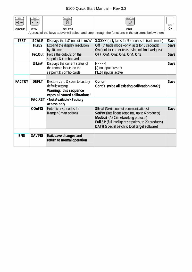
TEST SCALE Displays the L/C output in mV/V X.XXXX (only lasts for 5 seconds in trade mode) Save Hi.rES Expand the display resolution
by 10 times Off (In trade mode –only lasts for 5 seconds) On (tool for corner tests using minimal weights)
Save
Frc.Out Force the outputs on the setpoint & combo cards
OFF, On1, On2, On3, On4, On5
Save
tSt.inP Displays the current status of the remote inputs on the setpoint & combo cards
[- - - - -] [-] no input present [1..5] input is active
Save
FACTRY DEFLT Restore zero & span to factory
default settings Warning: this sequence wipes all stored calibrations!
Cont n Cont Y (wipe all existing calibration data?)
Save
FAC.RST <Not Available> Factory access only
COnFIG Enter license codes for Ranger-Smart options
SErial (Serial output communications) SetPnt (Intelligent setpoints, up to 6 products) ModbuS (ASCii networking protocol) Full.SP (full intelligent setpoints, to 20 products) DATH (special batch to total target software)
Save
END SAVING Exit, save changes and
return to normal operation

5100 Quick Start Manual – Rev 3.3
Error Messages The 5100 displays the following error messages. Short messages (xxxxx) will appear as a single message on the display. Longer messages (xxxxx)(yyyyy) will appear on the display in two parts, first the (xxxxx) part, then the (yyyyy) part.
WEIGHING ERRORS
(U-----) The weight is below the minimum allowable weight reading. (O-----) The weight is above the maximum allowable weight reading. (ZERO) (ERROR) The weight reading is beyond the limit set for Zero operation. (STABLE)(ERROR) Scale motion has prevented a Zero, Tare or Print operation from occurring on command. (PRINT) (ERROR) Printer is ofline. (Check printer power, no paper or cable fault.) (QA)(DUE) The “calibration due” date has been set and the current date exceeds this limit.
SETUP & CALIBRATION ERRORS
(RES) (LO) The scale build is configured for less than 100 graduations. (Check the resolution (count-by) and Capacity settings)
(RES) (HIGH) The scale build is configured for more than 100,000 graduations. (Check the resolution (count-by) and Capacity settings)
(ZERO) (HI) The load cell output is beyond allowable zero calibration range. (Check for incorrect scale connection)
(ZERO) (LO) The load cell output is below allowable zero calibration range. (Check for incorrect scale connection)
(SPAN) (LO) The load cell signal range (span) is too small for these settings. (Incorrect span weight entered. Scale wiring incorrect. Wrong load cell capacity [too large]. Wrong or no calibration weight added to scale.)
(SPAN) (HI) The load cell signal range (span) is too large for these settings. (Incorrect span weight entered. Scale wiring incorrect. Load cell capacity too small for application.)
(NO) (ZERO) There is no valid zero calibration so the span calibration cannot proceed.
DIAGNOSTIC ERRORS
(E 0001) The power supply voltage is too low. (check supply) (E 0002) The power supply voltage is too high. (check scale / cables) (E 0004) The load cell excitation voltage is too low. (check scale/supply) (E 0008) The load cell excitation voltage is too high. (check scale/supply) (E 0010) The temperature is outside of allowable limits. (check location) (E 0020) Scale build is incorrect. The number of graduations has been set less than 100 or greater
than 100 000. (fix up scale build) (E 0040) The positive sense line is not connected. (check connection) (E 0080) The negative sense line is not connected.(check connection) (E 00C0) Neither sense line is connected (check connection) (E 0100) The digital setup information has been lost. (re-enter setup) (E 0200) The calibration information has been lost. (re-calibrate) (E 0300) All setup information has been lost (enter setup and calibrate) (E 0400) The factory information has been lost. (return for factory service) (E 0800) The EEPROM memory storage chip has failed (service) (E 2000) The Clock Calendar chip has failed (service) (E 4000) The battery backed RAM has lost data. (E 8000) The EPROM memory storage chip has failed (service)
Diagnostic errors are additive to allow multiple faults to be displayed. (For example E0005 would indicate Power Supply and Excitation Voltage is low)

5100 Quick Start Manual – Rev 3.3
Notes:

5100 Quick Start Manual – Rev 3.3
Notes: