Embed Size (px)
Citation preview
55:035Computer Architecture and Organization
Lecture 2
Outline Information representation Arithmetic operations (addition and subtraction) Instruction Formats Addressing Modes Assembly Language Programming Basic input/output operations Subroutine linkage
255:035 Computer Architecture and Organization
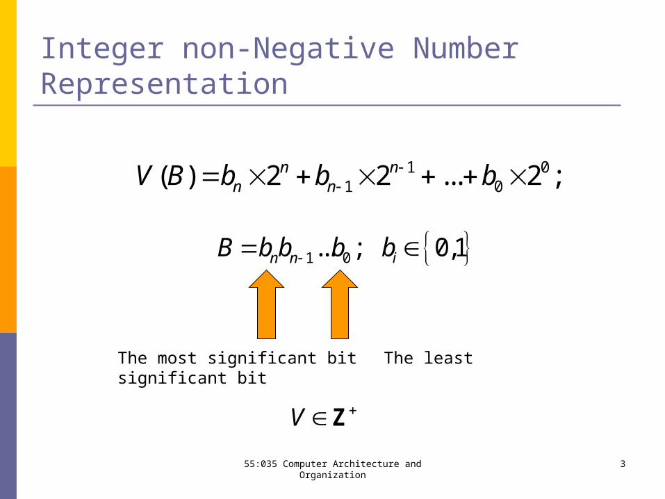
Integer non-Negative Number Representation
1 0... ; 0,1n n iB b b b b
1 01 0( ) 2 2 ... 2 ;n n
n nV B b b b
V Z
The most significant bit The least significant bit
355:035 Computer Architecture and Organization
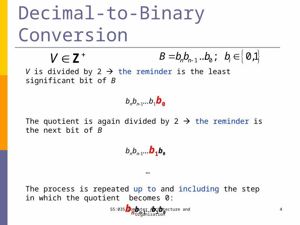
Decimal-to-Binary ConversionV Z
V is divided by 2 the reminder is the least significant bit of B
bnbn-1…b1b0
The quotient is again divided by 2 the reminder is the next bit of B
bnbn-1…b1b0
…
The process is repeated up to and including the step in which the quotient becomes 0:
bnbn-1…b1b0
1 0... ; 0,1n n iB b b b b
455:035 Computer Architecture and Organization
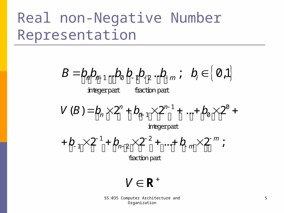
Real non-Negative Number Representation
1 0 1 2
integer part fraction part
... ... ; 0,1n n m iB b b b b b b b
1 01 0
integer part
1 21 2
fraction part
( ) 2 2 ... 2
2 2 ... 2 ;
n nn n
mn m
V B b b b
b b b
V R555:035 Computer Architecture and Organization
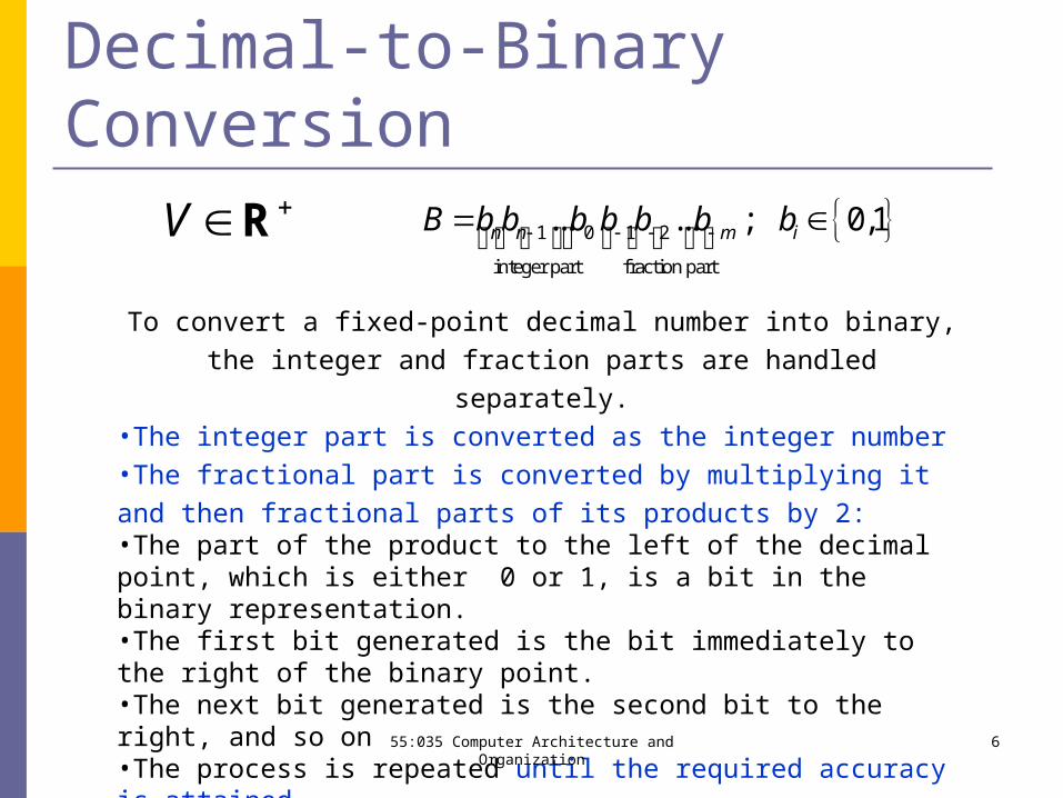
Decimal-to-Binary ConversionV R
To convert a fixed-point decimal number into binary, the integer and
fraction parts are handled separately.•The integer part is converted as the integer number•The fractional part is converted by multiplying it and then fractional
parts of its products by 2:•The part of the product to the left of the decimal point, which is either 0 or 1, is a bit in the binary representation.•The first bit generated is the bit immediately to the right of the binary point. •The next bit generated is the second bit to the right, and so on•The process is repeated until the required accuracy is attained
1 0 1 2
integer part fraction part
... ... ; 0,1n n m iB b b b b b b b
655:035 Computer Architecture and Organization
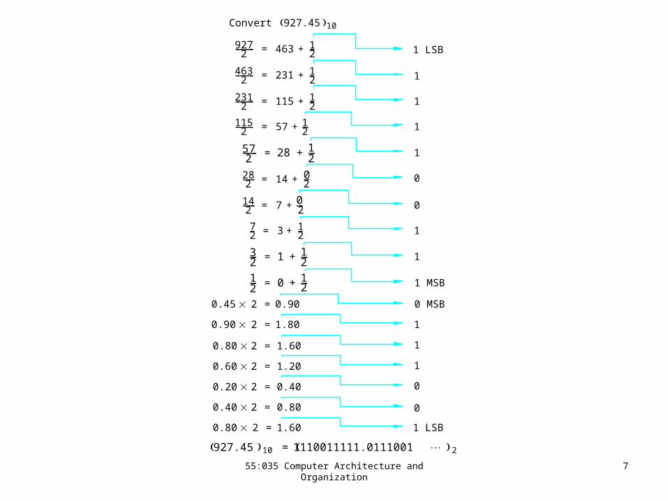
9272--------- 463 1
2---+=
4632--------- 231 1
2---+=
2312--------- 115 1
2---+=
1152--------- 57 1
2---+=
572------ 28 1
2---+=
282------ 14 0
2---+=
142------ 7 0
2---+=
72--- 3 1
2---+=
32--- 1 1
2---+=
12--- 0 1
2---+=
1 LSB
1 MSB
1
1
1
1
0
0
1
1
0.45 2 0.90=
0.90 2 1.80=
0.80 2 1.60=
0.60 2 1.20=
0.20 2 0.40=
0.40 2 0.80=
0.80 2 1.60=
0 MSB
1 LSB
1
1
1
0
0
Convert
927.45 10 1110011111.0111001 2=
927.45 10
755:035 Computer Architecture and Organization
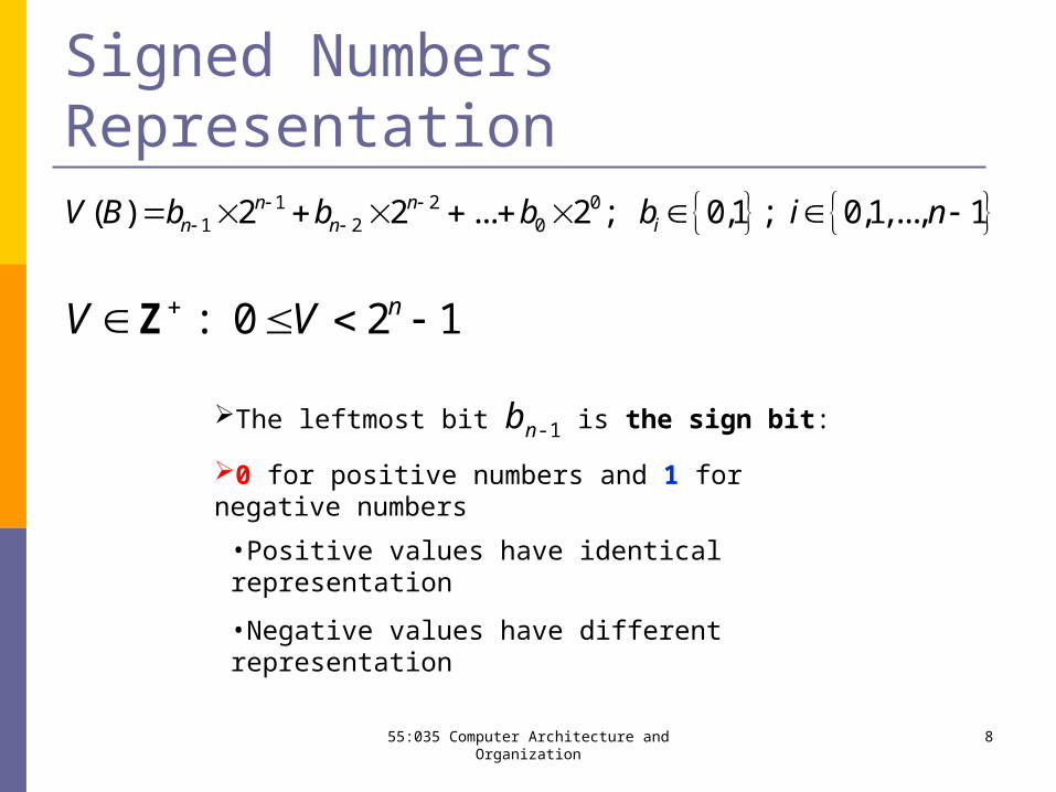
Signed Numbers Representation 1 2 0
1 2 0( ) 2 2 ... 2 ; 0,1 ; 0,1,..., 1n nn n iV B b b b b i n
: 0 2 1nV V Z
The leftmost bit bn-1 is the sign bit:
0 for positive numbers and 1 for negative numbers
•Positive values have identical representation
•Negative values have different representation
855:035 Computer Architecture and Organization
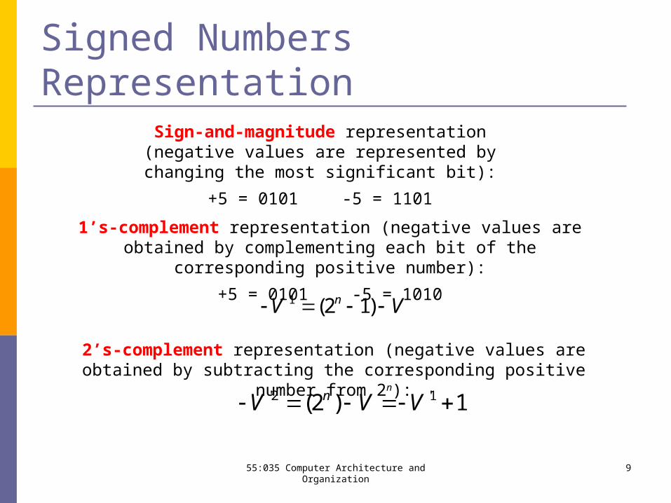
Signed Numbers RepresentationSign-and-magnitude representation (negative values are represented by changing the most significant bit):
+5 = 0101 -5 = 1101
'1 (2 1)nV V
1’s-complement representation (negative values are obtained by complementing each bit of the corresponding positive number):
+5 = 0101 -5 = 1010
2’s-complement representation (negative values are obtained by subtracting the corresponding positive number from 2n):
'2 '1(2 ) 1nV V V
955:035 Computer Architecture and Organization
0000000011111111
00000000
1111
1111
1100110000110011
1010101001010101
1+
1-
2+3+4+5+6+7+
2-3-4-5-6-7-
8-0+0-
1+2+3+4+5+6+7+
0+7-6-5-4-3-2-1-0-
1+2+3+4+5+6+7+
0+
7-6-5-4-3-2-1-
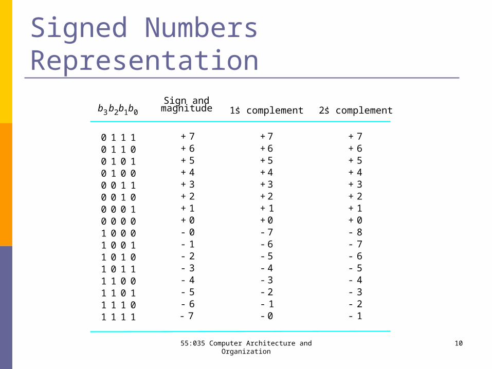
b3 b2b1b0
Sign andmagnitude 1' s complement 2' s complement
Signed Numbers Representation
1055:035 Computer Architecture and Organization
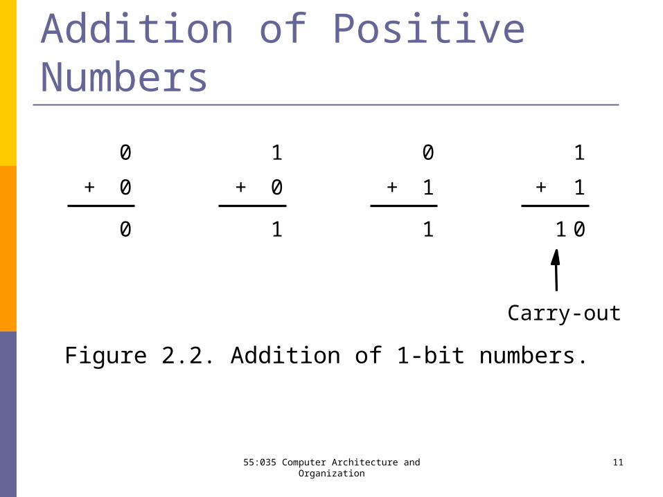
Figure 2.2. Addition of 1-bit numbers.
Carry-out
1
1
+
011
0
1+
0
0
0
+
1
0
1
+
Addition of Positive Numbers
1155:035 Computer Architecture and Organization
S/M and 1’s-Complement Representation
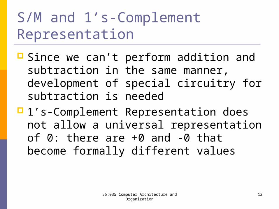
Since we can’t perform addition and subtraction in the same manner, development of special circuitry for subtraction is needed
1’s-Complement Representation does not allow a universal representation of 0: there are +0 and -0 that become formally different values
1255:035 Computer Architecture and Organization
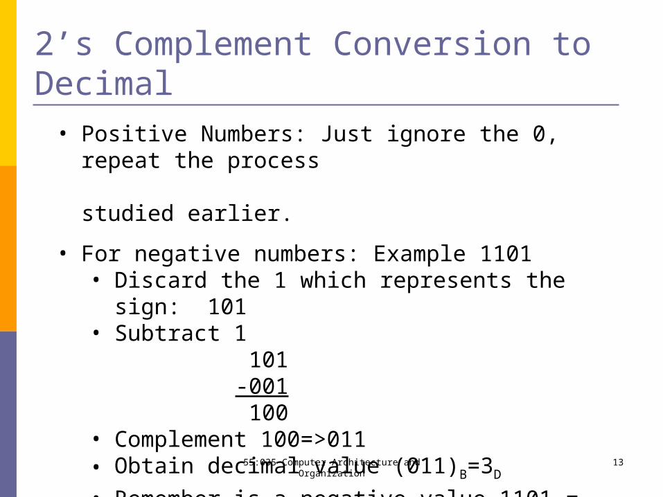
2’s Complement Conversion to Decimal• Positive Numbers: Just ignore the 0, repeat the process studied earlier.
• For negative numbers: Example 1101• Discard the 1 which represents the sign: 101• Subtract 1 101 -001 100• Complement 100=>011• Obtain decimal value (011)B=3D
• Remember is a negative value 1101 = -3
1355:035 Computer Architecture and Organization
Decimal Conversion to 2’s Complement
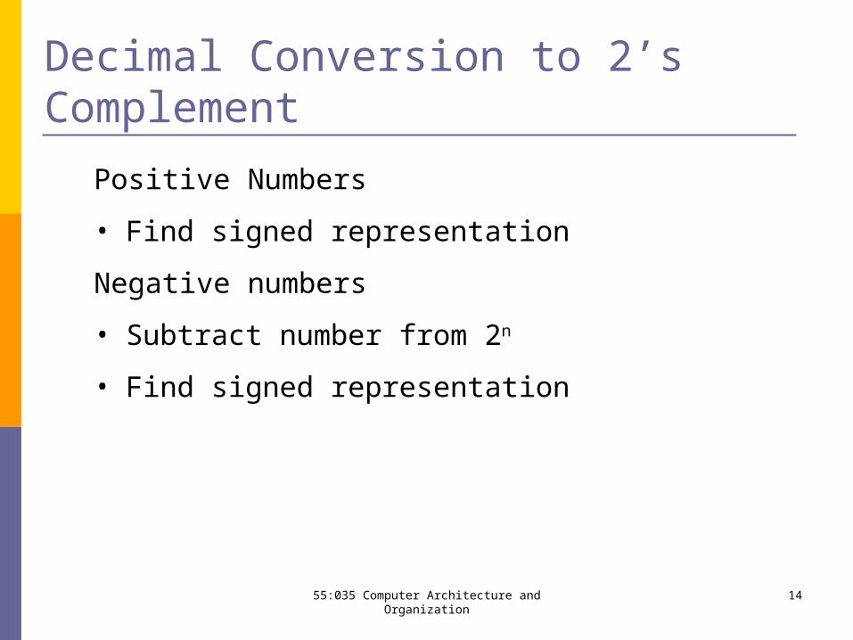
Positive Numbers
• Find signed representation
Negative numbers
• Subtract number from 2n
• Find signed representation
1455:035 Computer Architecture and Organization
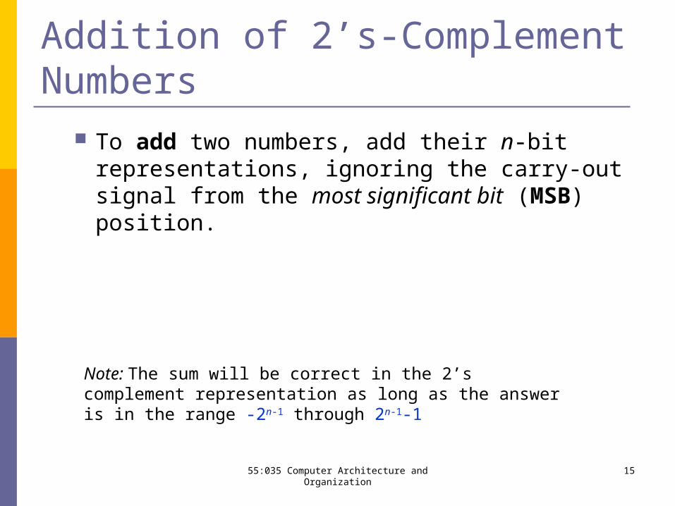
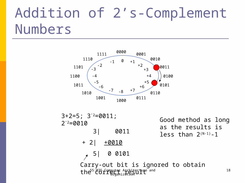
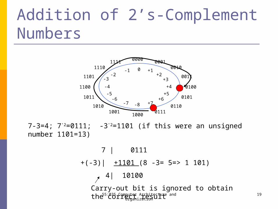
Addition of 2’s-Complement Numbers To add two numbers, add their n-bit representations,
ignoring the carry-out signal from the most significant bit (MSB) position.
Note: The sum will be correct in the 2’s complement representation as long as the answer is in the range -2n-1 through 2n-1-1
1555:035 Computer Architecture and Organization
Subtraction of 2’s-Complement Numbers
To subtract two numbers X and Y, that is, to perform X-Y, form the 2’s-complement of Y and then add it to X according to the addition rule.
Note: The result will be correct in the 2’s complement representation as long as the answer is in the range -2n-1 through 2n-
1-1
1655:035 Computer Architecture and Organization

Figure 2.3. Modular number systems and the 2's-complement system.
N 2-N 1-
01
2
(a) Circle representation of integers mod N
00000001
0010
0011
0100
0101
01100111
10001001
1010
1011
1100
1101
11101111
1+1-2+
3+
4+
5+6+
7+
2-3-
4-
5-6-
7- 8-
0
(b) Mod 16 system for 2's-complement numbers
2’s Complement System
1755:035 Computer Architecture and Organization
Addition of 2’s-Complement Numbers
00000001
0010
0011
0100
0101
01100111
10001001
1010
1011
1100
1101
11101111
+1-1+2
+3
+4
+5+6
+7
-2
-4
-5-6
-7 -8
0
-3
3+2=5; 3’2=0011; 2’2=0010
3| 0011
+ 2| +0010
5| 0 0101
Carry-out bit is ignored to obtain the correct result
Good method as long as the results is less than 2(N-1)-1
1855:035 Computer Architecture and Organization
Addition of 2’s-Complement Numbers
00000001
0010
0011
0100
0101
01100111
10001001
1010
1011
1100
1101
11101111
+1-1+2
+3
+4
+5+6
+7
-2
-4
-5-6
-7 -8
0
-3
7-3=4; 7’2=0111; -3’2=1101 (if this were an unsigned number 1101=13)
7 | 0111
+(-3)| +1101 (8 -3= 5=> 1 101)
4| 10100
Carry-out bit is ignored to obtain the correct result1955:035 Computer Architecture and Organization
2’s-Complement Addition The 2’s-Complement System is the most
efficient for addition and subtraction of signed numbers because both can be performed in the same manner for both positive and negative numbers
Same manner=Same circuitry=Less $$$$
2055:035 Computer Architecture and Organization
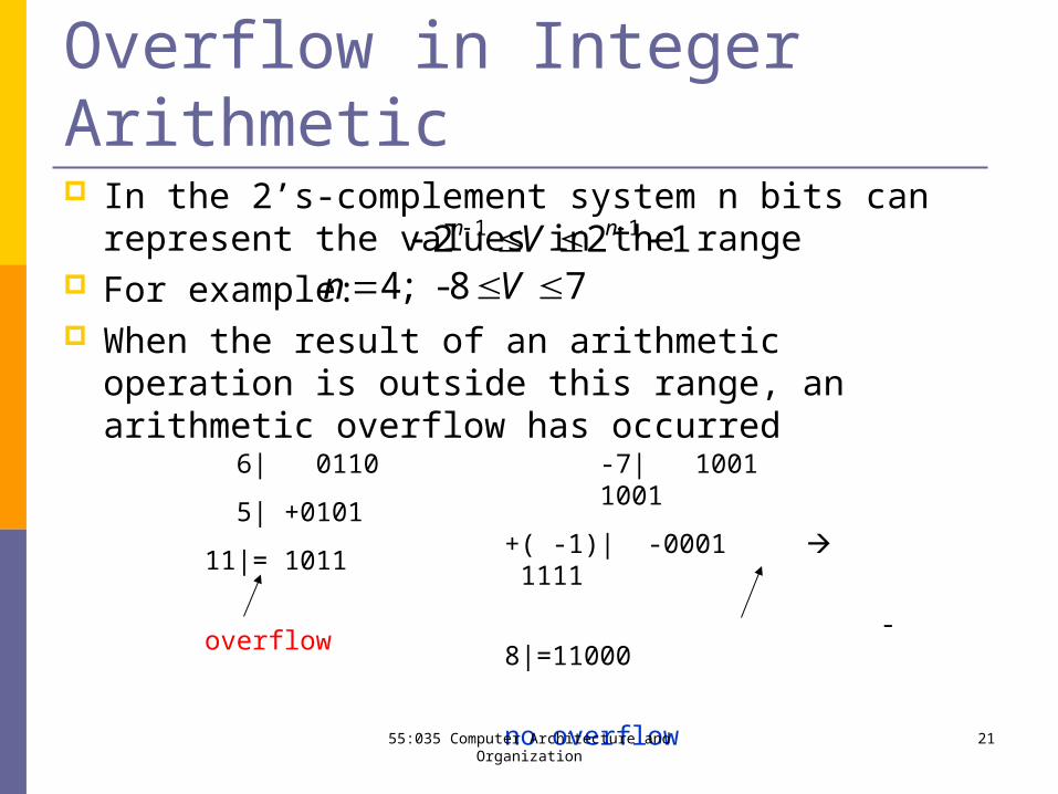
Overflow in Integer Arithmetic1 12 2 1n nV
In the 2’s-complement system n bits can represent the values in the range
For example: When the result of an arithmetic operation is outside this
range, an arithmetic overflow has occurred
78- ;4 Vn
6| 0110
5| +0101
11|= 1011
overflow
-7| 1001 1001
+( -1)| -0001 1111
-8|=11000
no overflow
2155:035 Computer Architecture and Organization
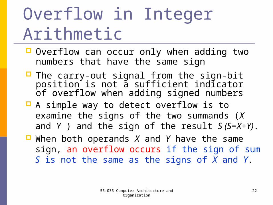
Overflow in Integer Arithmetic
A simple way to detect overflow is to examine the signs of the two summands (X and Y ) and the sign of the result S (S=X+Y).
When both operands X and Y have the same sign, an overflow occurs if the sign of sum S is not the same as the signs of X and Y.
Overflow can occur only when adding two numbers that have the same sign
The carry-out signal from the sign-bit position is not a sufficient indicator of overflow when adding signed numbers
2255:035 Computer Architecture and Organization
1 0 1 11 1 1 0
1 0 0 1
1 1 0 11 0 0 1
0 0 1 00 1 0 0
0 1 1 00 0 1 1
1 0 0 11 0 1 1
1 0 0 10 0 0 1
0 0 1 01 1 0 1
1 1 1 0
0 1 0 01 0 1 0
0 1 1 11 1 0 1
0 1 0 0
1 1 0 10 1 1 1
0 1 0 0
0 0 1 01 1 0 0
1 1 1 0
0 1 1 01 1 0 1
0 0 1 1
1 0 0 10 1 0 1
1 1 1 0
1 0 0 11 1 1 1
1 0 0 0
0 0 1 00 0 1 1
0 1 0 1
0 1 0 1
0 0 1 00 0 1 1
5-
2+( )3+( )
5+( )
2+( )4+( )
2- 7- 3- 7-
6+( )3+( )
1+( )
7- 5-
7-
2+( )3-
6- 2-
4+( )
3- 4+( )
7+( )
4+( )
2-
3+( )
2-
8-
5+( )+
+
+
+
+
+
+
+
+
+
-
-
-
-
-
-
(a)
(c)
(b)
(d)
(e)
(f)
(g)
(h)
(i)
(j)
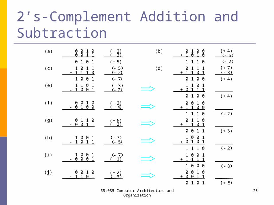
2’s-Complement Addition and Subtraction
2355:035 Computer Architecture and Organization
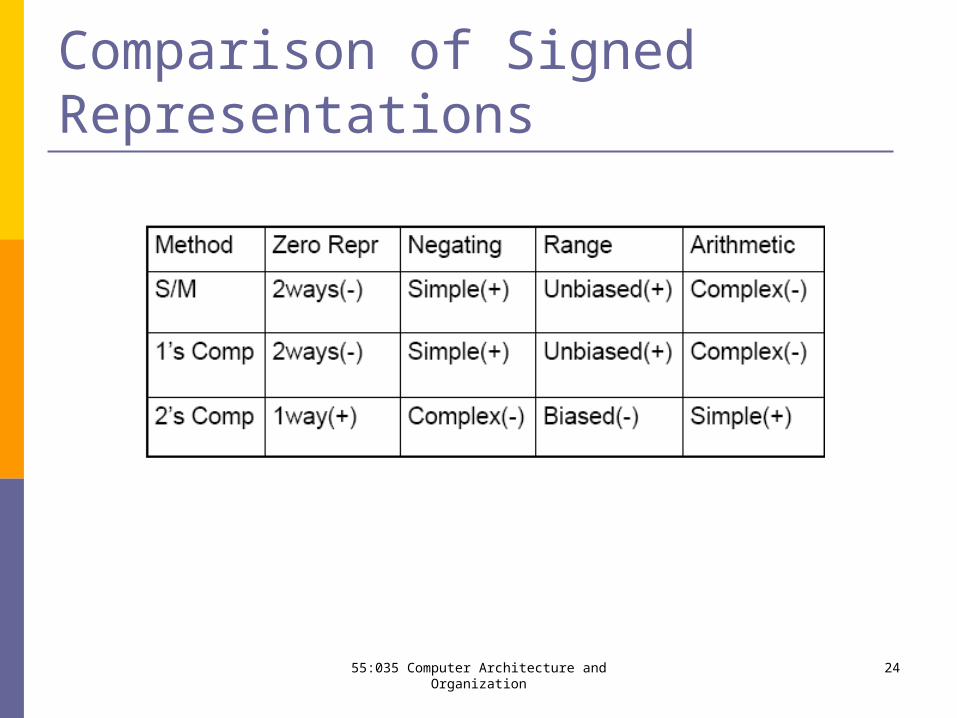
Comparison of Signed Representations
2455:035 Computer Architecture and Organization
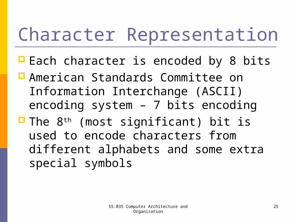
Character Representation Each character is encoded by 8 bits American Standards Committee on Information
Interchange (ASCII) encoding system – 7 bits encoding
The 8th (most significant) bit is used to encode characters from different alphabets and some extra special symbols
2555:035 Computer Architecture and Organization
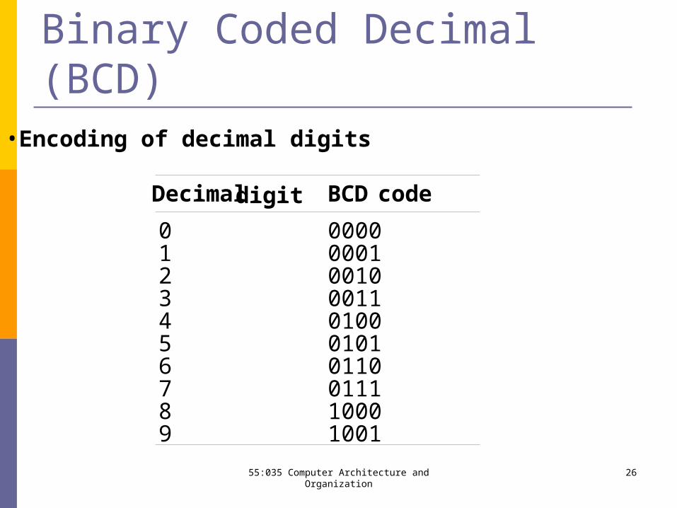
•Encoding of decimal digits
Decimaldigit BCDcode
0 00001 00012 00103 00114 01005 01016 01107 01118 10009 1001
Binary Coded Decimal (BCD)
2655:035 Computer Architecture and Organization
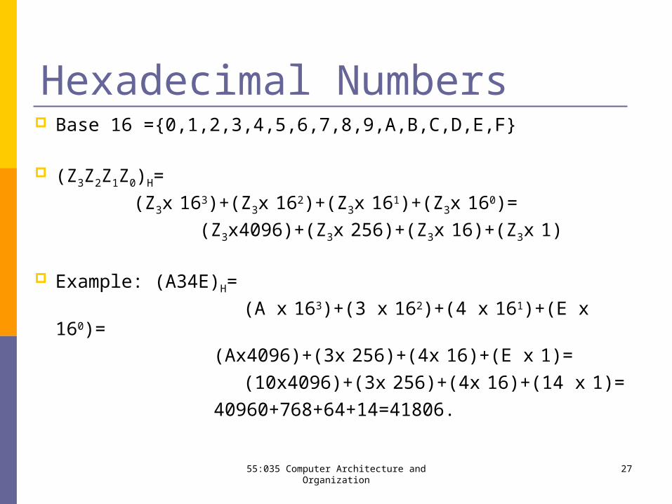
Hexadecimal Numbers Base 16 ={0,1,2,3,4,5,6,7,8,9,A,B,C,D,E,F}
(Z3Z2Z1Z0)H=
(Z3x 163)+(Z3x 162)+(Z3x 161)+(Z3x 160)=
(Z3x4096)+(Z3x 256)+(Z3x 16)+(Z3x 1)
Example: (A34E)H=
(A x 163)+(3 x 162)+(4 x 161)+(E x 160)=
(Ax4096)+(3x 256)+(4x 16)+(E x 1)=
(10x4096)+(3x 256)+(4x 16)+(14 x 1)=
40960+768+64+14=41806.2755:035 Computer Architecture and Organization
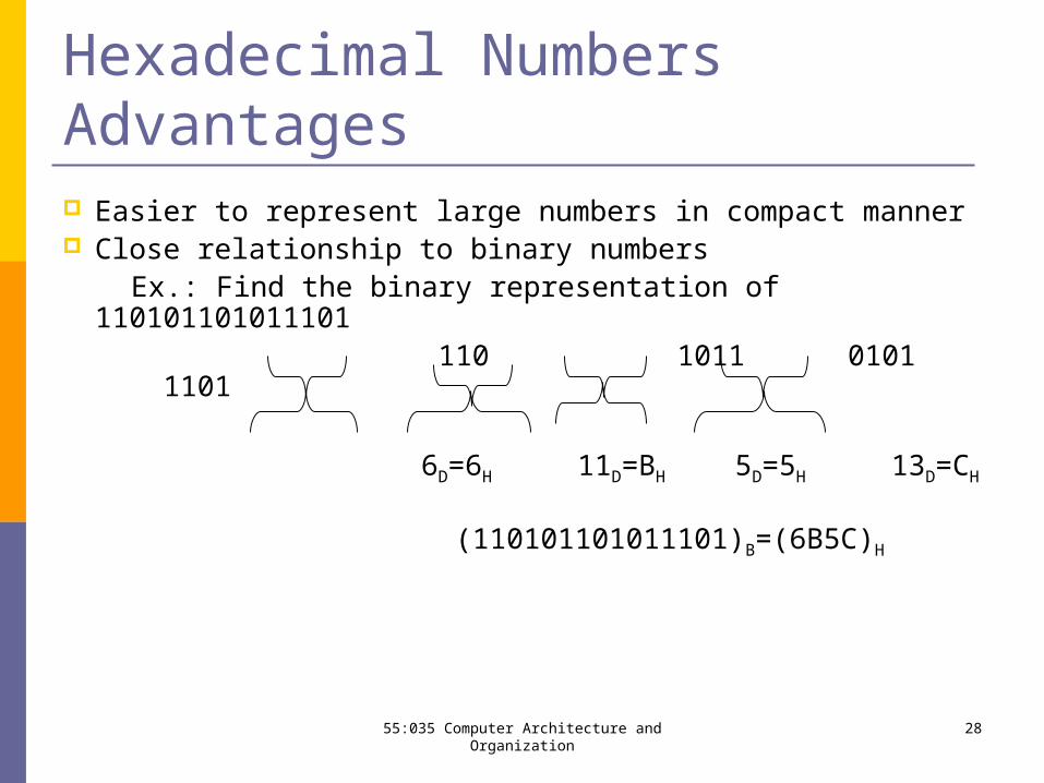
Hexadecimal Numbers Advantages Easier to represent large numbers in compact manner Close relationship to binary numbers Ex.: Find the binary representation of 110101101011101 110 1011 0101 1101
6D=6H 11D=BH 5D=5H 13D=CH
(110101101011101)B=(6B5C)H
2855:035 Computer Architecture and Organization
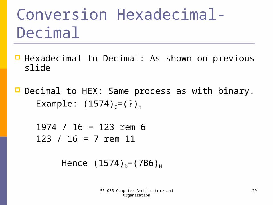
Conversion Hexadecimal-Decimal
Hexadecimal to Decimal: As shown on previous slide
Decimal to HEX: Same process as with binary.
Example: (1574)D=(?)H
1974 / 16 = 123 rem 6123 / 16 = 7 rem 11
Hence (1574)D=(7B6)H
2955:035 Computer Architecture and Organization
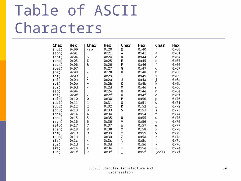
Table of ASCII Characters Char Hex Char Hex Char Hex Char Hex(nul) 0x00 (sp) 0x20 @ 0x40 ` 0x60(soh) 0x01 ! 0x21 A 0x41 a 0x61(eot) 0x04 $ 0x24 D 0x44 d 0x64(enq) 0x05 % 0x25 E 0x45 e 0x65(ack) 0x06 & 0x26 F 0x46 f 0x66(bel) 0x07 ' 0x27 G 0x47 g 0x67(bs) 0x08 ( 0x28 H 0x48 h 0x68(ht) 0x09 ) 0x29 I 0x49 i 0x69(nl) 0x0a * 0x2a J 0x4a j 0x6a(vt) 0x0b + 0x2b K 0x4b k 0x6b(cr) 0x0d - 0x2d M 0x4d m 0x6d(so) 0x0e . 0x2e N 0x4e n 0x6e(si) 0x0f / 0x2f O 0x4f o 0x6f(dle) 0x10 0 0x30 P 0x50 p 0x70(dc1) 0x11 1 0x31 Q 0x51 q 0x71(dc2) 0x12 2 0x32 R 0x52 r 0x72(dc3) 0x13 3 0x33 S 0x53 s 0x73(dc4) 0x14 4 0x34 T 0x54 t 0x74(nak) 0x15 5 0x35 U 0x55 u 0x75(syn) 0x16 6 0x36 V 0x56 v 0x76(etb) 0x17 7 0x37 W 0x57 w 0x77(can) 0x18 8 0x38 X 0x58 x 0x78(em) 0x19 9 0x39 Y 0x59 y 0x79(sub) 0x1a : 0x3a Z 0x5a z 0x7a(fs) 0x1c < 0x3c \ 0x5c | 0x7c(gs) 0x1d = 0x3d ] 0x5d } 0x7d(rs) 0x1e > 0x3e ^ 0x5e ~ 0x7e(us) 0x1f ? 0x3f _ 0x5f (del) 0x7f
3055:035 Computer Architecture and Organization
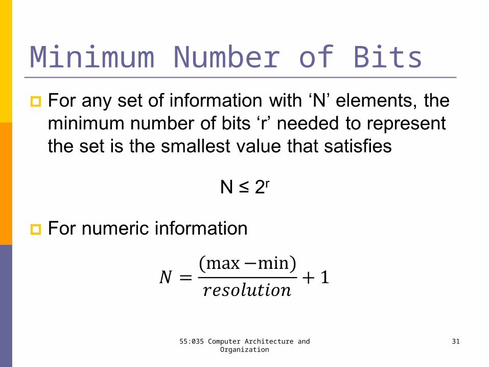
Minimum Number of Bits
55:035 Computer Architecture and Organization 31
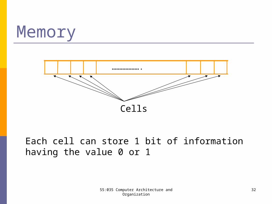
Memory
Cells
……………….
Each cell can store 1 bit of information having the value 0 or 1
3255:035 Computer Architecture and Organization
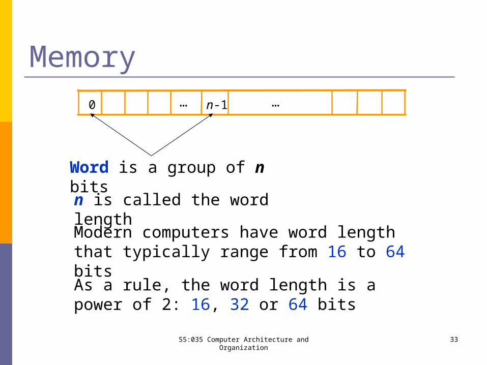
Memory
Word is a group of n bits
…
n is called the word length
…0 n-1
Modern computers have word length that typically range from 16 to 64 bits
As a rule, the word length is a power of 2: 16, 32 or 64 bits
3355:035 Computer Architecture and Organization
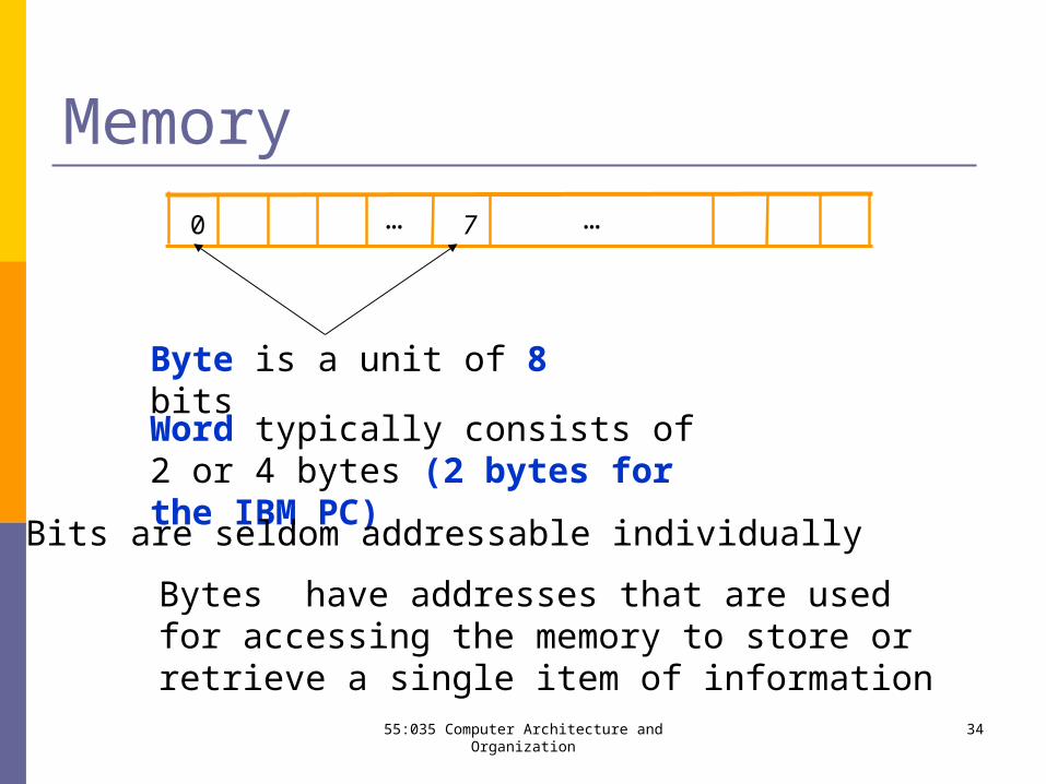
Memory
Byte is a unit of 8 bits
…
Word typically consists of 2 or 4 bytes (2 bytes for the IBM PC)
…0 7
Bits are seldom addressable individually
Bytes have addresses that are used for accessing the memory to store or retrieve a single item of information
3455:035 Computer Architecture and Organization
Byte Addressability
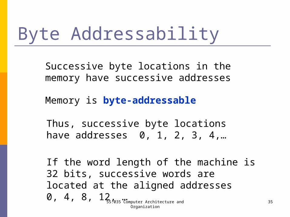
Successive byte locations in the memory have successive addresses
Memory is byte-addressable
Thus, successive byte locations have addresses 0, 1, 2, 3, 4,…
If the word length of the machine is 32 bits, successive words are located at the aligned addresses 0, 4, 8, 12, …
3555:035 Computer Architecture and Organization
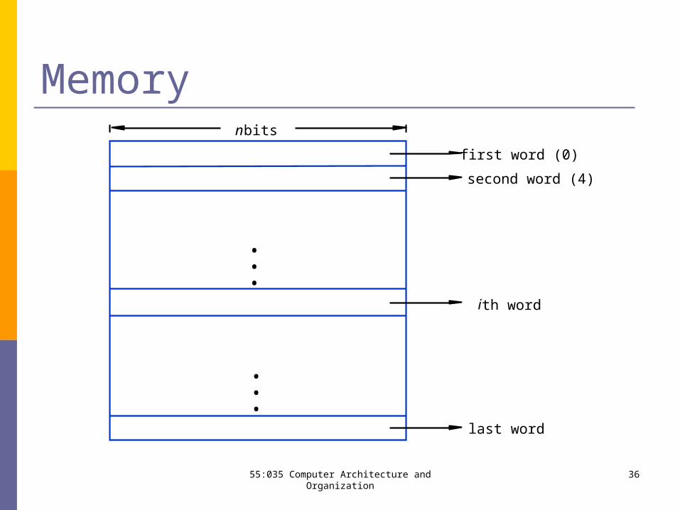
second word (4)
first word (0)
n bits
last word
i th word
•••
•••
Memory
3655:035 Computer Architecture and Organization
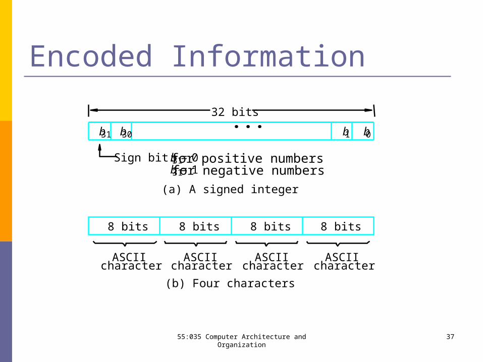
(b) Four characters
charactercharactercharacter character
(a) A signed integer
Sign bit: for positive numbers for negative numbers
ASCIIASCIIASCIIASCII
32 bits
8 bits 8 bits 8 bits 8 bits
b31 b30 b1 b0
b31 0=b31 1=
• • •
Encoded Information
3755:035 Computer Architecture and Organization
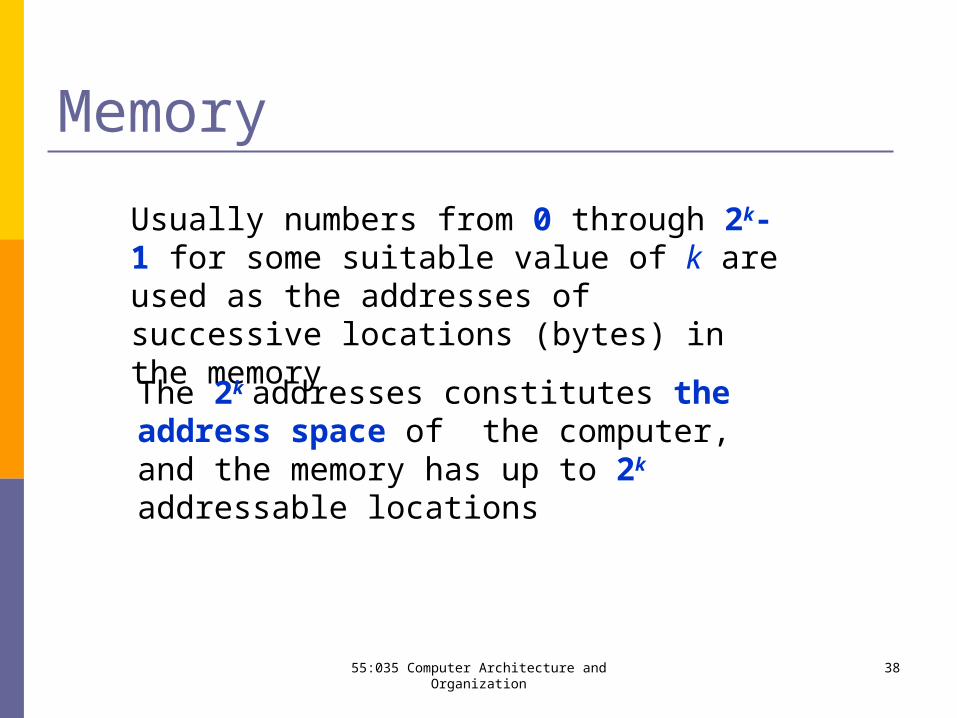
Memory
Usually numbers from 0 through 2k-1 for some suitable value of k are used as the addresses of successive locations (bytes) in the memory
The 2k addresses constitutes the address space of the computer, and the memory has up to 2k addressable locations
3855:035 Computer Architecture and Organization
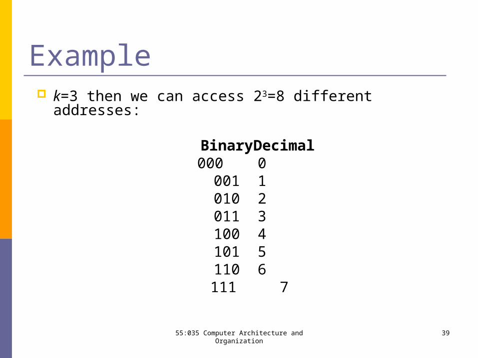
Example k=3 then we can access 23=8 different addresses:
Binary Decimal000 0
001 1010 2011 3100 4101 5110 6
111 7
3955:035 Computer Architecture and Organization
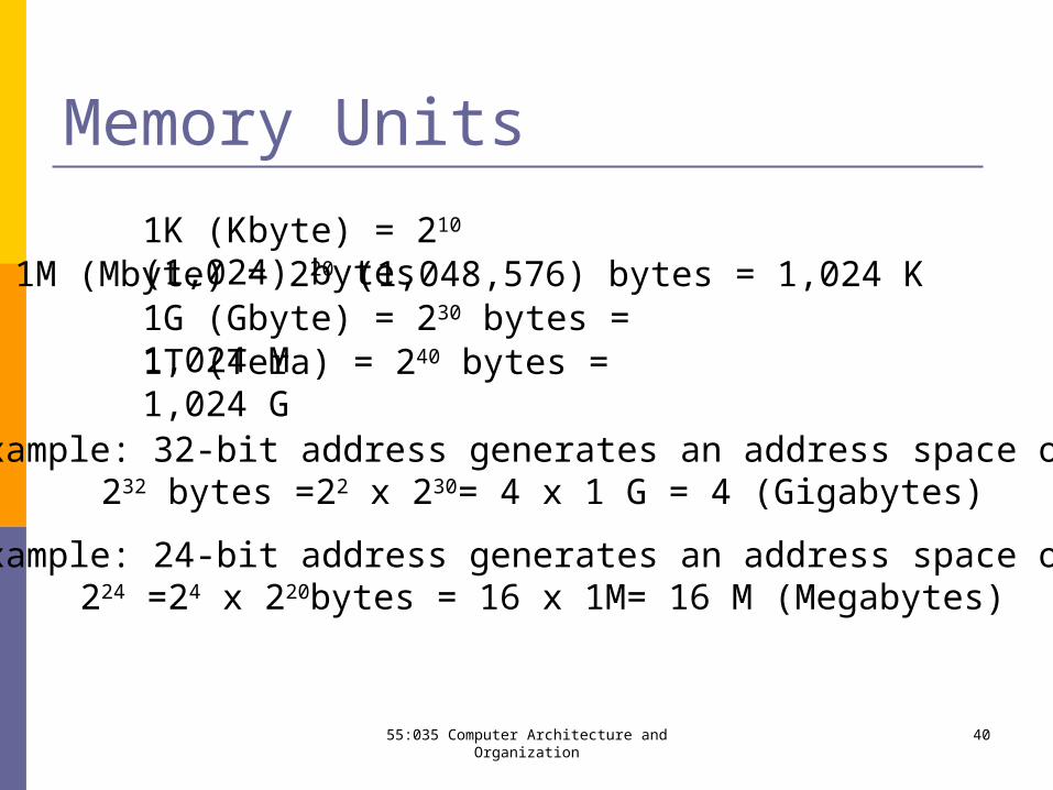
Memory Units
Example: 24-bit address generates an address space of 224 =24 x 220bytes = 16 x 1M= 16 M (Megabytes)
Example: 32-bit address generates an address space of 232 bytes =22 x 230= 4 x 1 G = 4 (Gigabytes)
1M (Mbyte) = 220 (1,048,576) bytes = 1,024 K1G (Gbyte) = 230 bytes = 1,024 M
1K (Kbyte) = 210 (1,024) bytes
1T (Tera) = 240 bytes = 1,024 G
4055:035 Computer Architecture and Organization
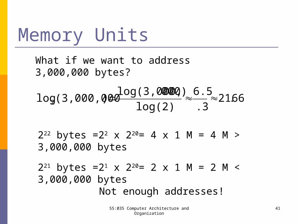
Memory UnitsWhat if we want to address 3,000,000 bytes?
66.21.3
6.5
log(2)
000)log(3,000,)(3,000,000log2
222 bytes =22 x 220= 4 x 1 M = 4 M > 3,000,000 bytes
221 bytes =21 x 220= 2 x 1 M = 2 M < 3,000,000 bytesNot enough addresses!
4155:035 Computer Architecture and Organization
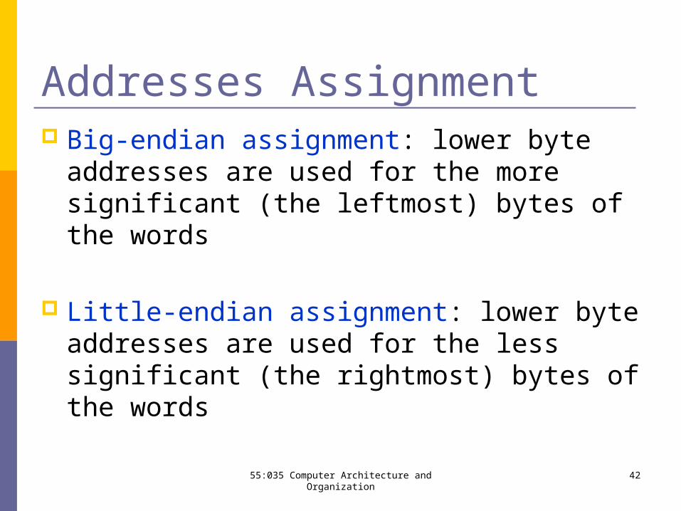
Addresses Assignment Big-endian assignment: lower byte addresses
are used for the more significant (the leftmost) bytes of the words
Little-endian assignment: lower byte addresses are used for the less significant (the rightmost) bytes of the words
4255:035 Computer Architecture and Organization
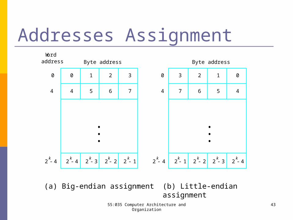
2k
4- 2k
3- 2k
2- 2k
1- 2k
4-2k
4-
0 1 2 3
4 5 6 7
0 0
4
2k
1- 2k
2- 2k
3- 2k
4-
3 2 1 0
7 6 5 4
Byte addressByte address
(a) Big-endian assignment (b) Little-endian assignment
4
Wordaddress
•••
•••
Addresses Assignment
4355:035 Computer Architecture and Organization
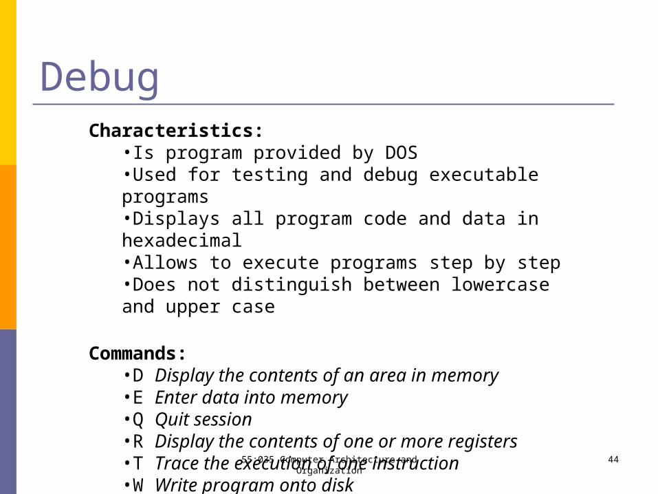
DebugCharacteristics:
•Is program provided by DOS•Used for testing and debug executable programs•Displays all program code and data in hexadecimal•Allows to execute programs step by step•Does not distinguish between lowercase and upper case
Commands:•D Display the contents of an area in memory•E Enter data into memory•Q Quit session•R Display the contents of one or more registers•T Trace the execution of one instruction•W Write program onto disk
4455:035 Computer Architecture and Organization
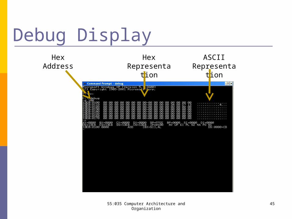
Debug DisplayHex
AddressHex
RepresentationASCII
Representation
4555:035 Computer Architecture and Organization
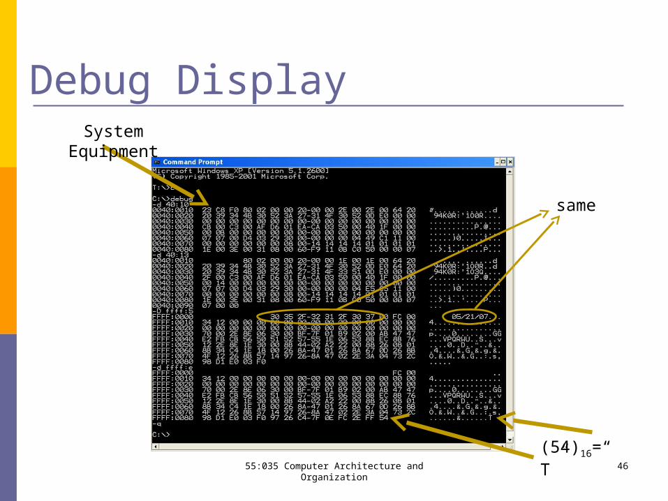
Debug DisplaySystem Equipment
(54)16=“T”
same
4655:035 Computer Architecture and Organization
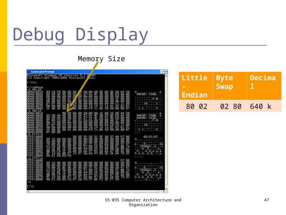
Debug DisplayMemory Size
Little-Endian
Byte Swap
Decimal
80 02 02 80 640 k
4755:035 Computer Architecture and Organization
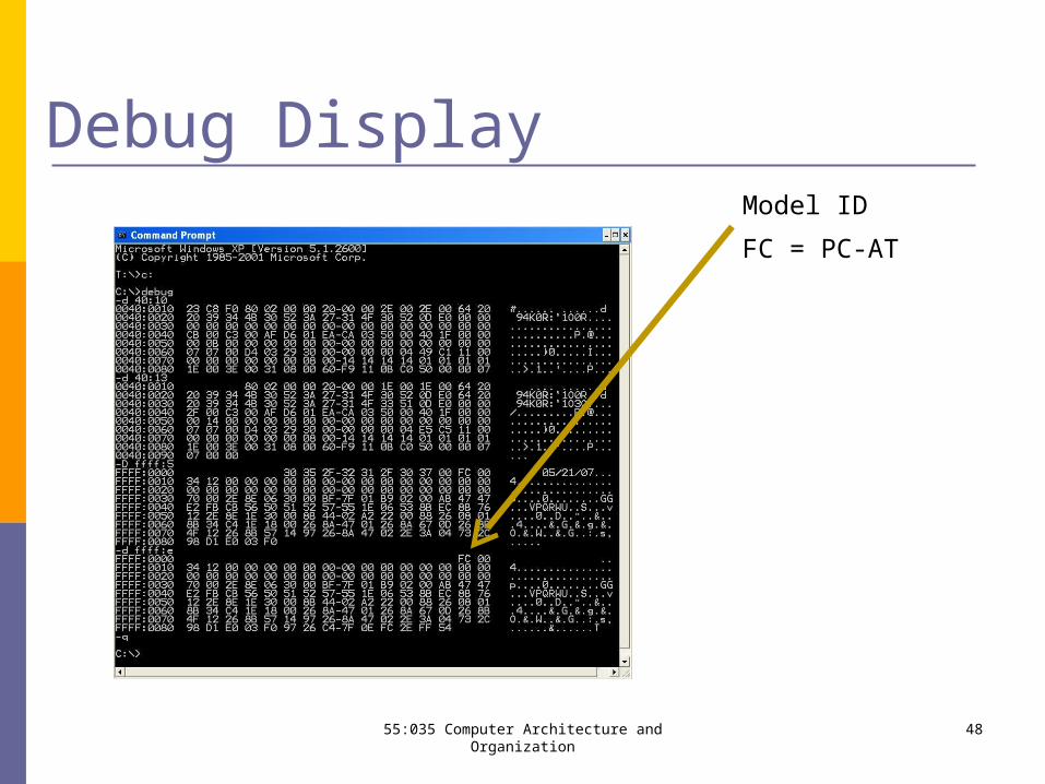
Debug DisplayModel ID
FC = PC-AT
4855:035 Computer Architecture and Organization
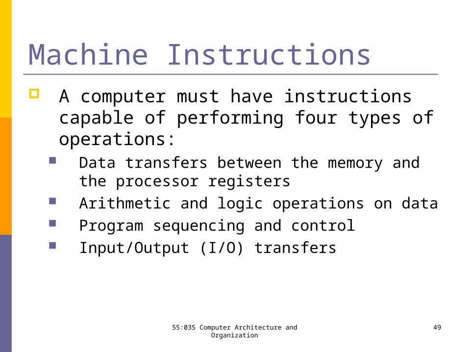
Machine Instructions A computer must have instructions capable of
performing four types of operations: Data transfers between the memory and the
processor registers Arithmetic and logic operations on data Program sequencing and control Input/Output (I/O) transfers
4955:035 Computer Architecture and Organization
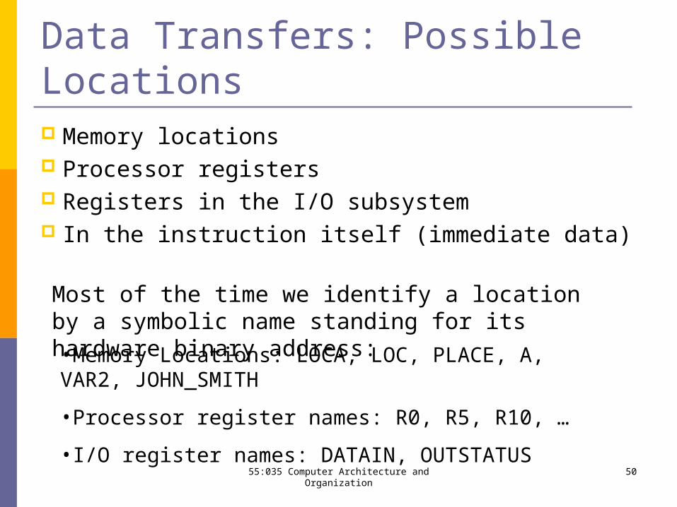
Data Transfers: Possible Locations Memory locations Processor registers Registers in the I/O subsystem In the instruction itself (immediate data)
Most of the time we identify a location by a symbolic name standing for its hardware binary address:•Memory Locations: LOCA, LOC, PLACE, A, VAR2, JOHN_SMITH
•Processor register names: R0, R5, R10, …
•I/O register names: DATAIN, OUTSTATUS
5055:035 Computer Architecture and Organization
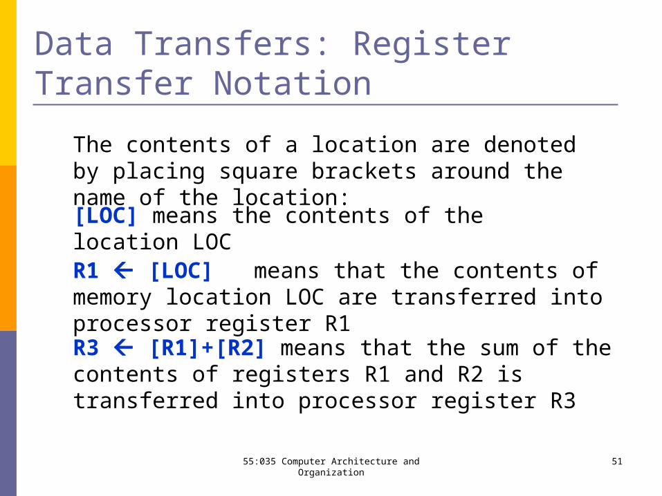
Data Transfers: Register Transfer Notation
The contents of a location are denoted by placing square brackets around the name of the location:
[LOC] means the contents of the location LOC
R1 [LOC] means that the contents of memory location LOC are transferred into processor register R1
R3 [R1]+[R2] means that the sum of the contents of registers R1 and R2 is transferred into processor register R3
5155:035 Computer Architecture and Organization
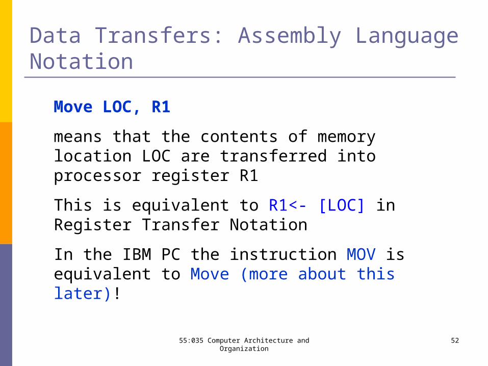
Data Transfers: Assembly Language Notation
Move LOC, R1
means that the contents of memory location LOC are transferred into processor register R1
This is equivalent to R1<- [LOC] in Register Transfer Notation
In the IBM PC the instruction MOV is equivalent to Move (more about this later)!
5255:035 Computer Architecture and Organization
Data Transfers: Assembly Language Notation
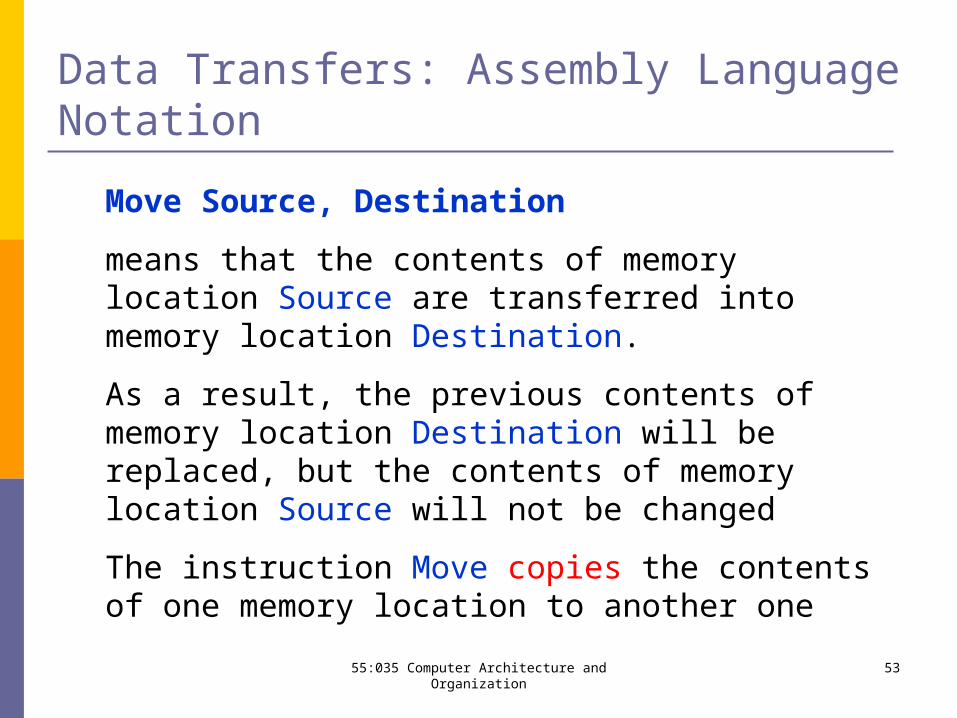
Move Source, Destination
means that the contents of memory location Source are transferred into memory location Destination.
As a result, the previous contents of memory location Destination will be replaced, but the contents of memory location Source will not be changed
The instruction Move copies the contents of one memory location to another one
5355:035 Computer Architecture and Organization
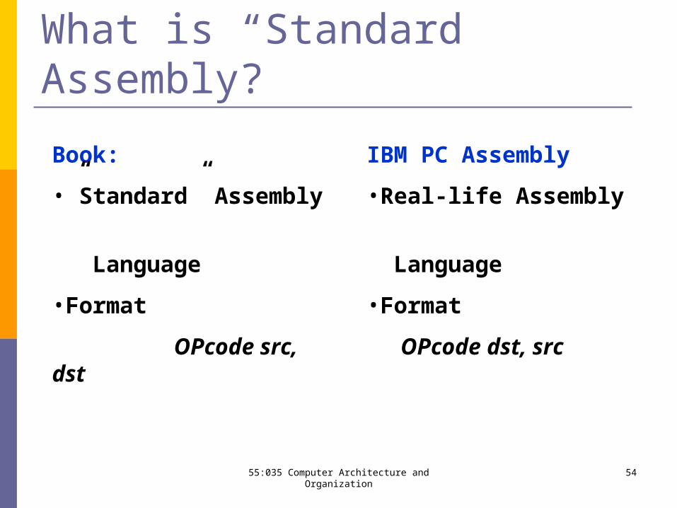
What is “Standard” Assembly?
Book:
•”Standard” Assembly
Language
•Format
OPcode src, dst
IBM PC Assembly
•Real-life Assembly
Language
•Format
OPcode dst, src
5455:035 Computer Architecture and Organization
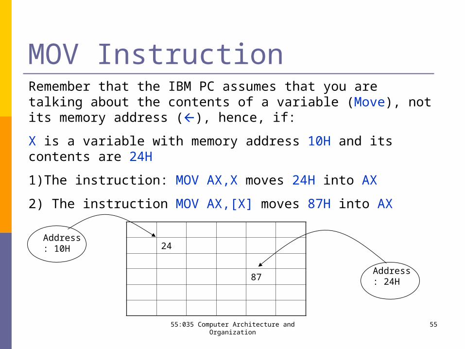
MOV InstructionRemember that the IBM PC assumes that you are talking about the contents of a variable (Move), not its memory address (), hence, if:
X is a variable with memory address 10H and its contents are 24H
1)The instruction: MOV AX,X moves 24H into AX
2) The instruction MOV AX,[X] moves 87H into AX
24
87
Address: 10H
Address: 24H
5555:035 Computer Architecture and Organization
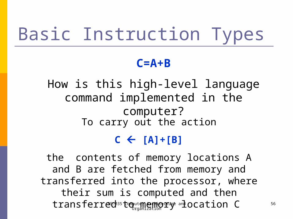
Basic Instruction Types
C=A+B
How is this high-level language command implemented in the computer?
To carry out the action
C [A]+[B]
the contents of memory locations A and B are fetched from memory and transferred into the processor, where their sum is computed and then transferred to memory
location C 5655:035 Computer Architecture and Organization
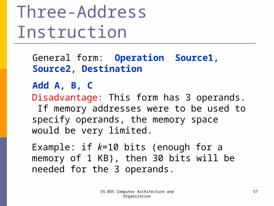
Three-Address InstructionGeneral form: Operation Source1, Source2, Destination
Add A, B, C
Disadvantage: This form has 3 operands. If memory addresses were to be used to specify operands, the memory space would be very limited.
Example: if k=10 bits (enough for a memory of 1 KB), then 30 bits will be needed for the 3 operands.
5755:035 Computer Architecture and Organization
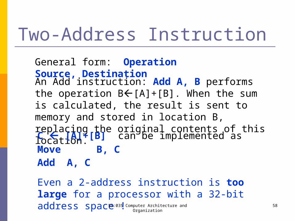
Two-Address InstructionGeneral form: Operation Source, Destination
An Add instruction: Add A, B performs the operation B[A]+[B]. When the sum is calculated, the result is sent to memory and stored in location B, replacing the original contents of this location.
C [A]+[B] can be implemented asMove B, CAdd A, C
Even a 2-address instruction is too large for a processor with a 32-bit address space !
5855:035 Computer Architecture and Organization
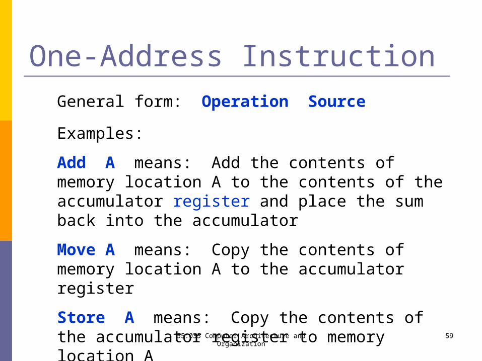
One-Address Instruction
Examples:
Add A means: Add the contents of memory location A to the contents of the accumulator register and place the sum back into the accumulator
Move A means: Copy the contents of memory location A to the accumulator register
Store A means: Copy the contents of the accumulator register to memory location A
General form: Operation Source
5955:035 Computer Architecture and Organization
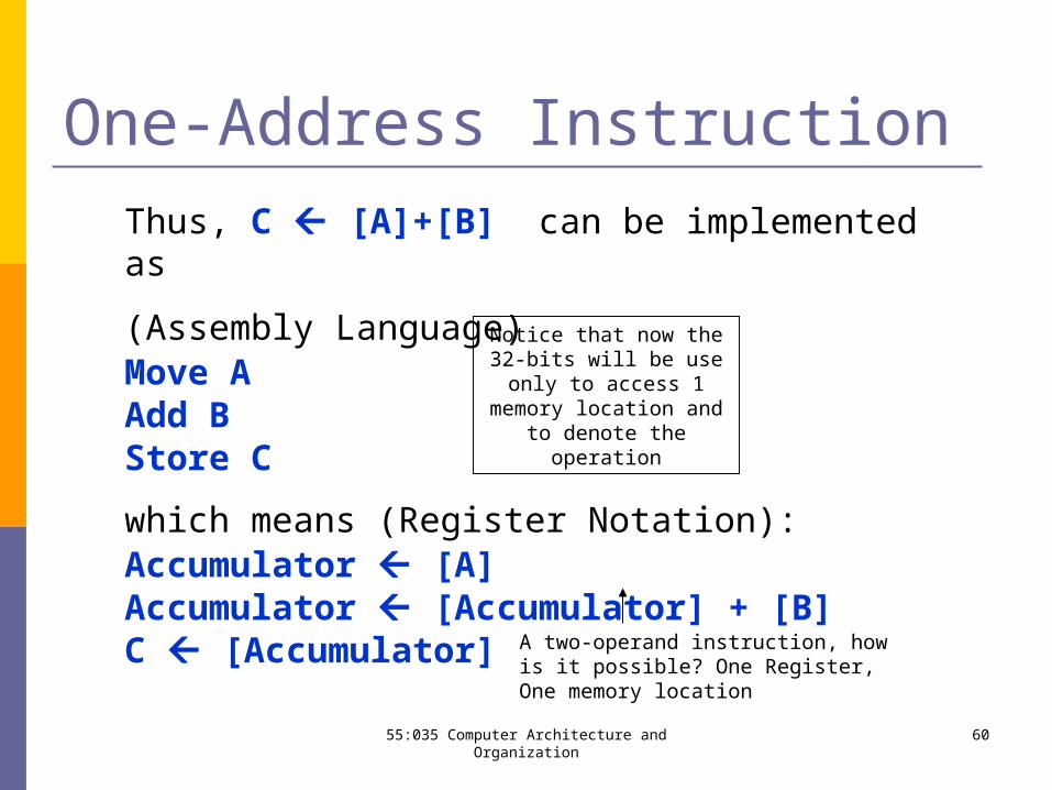
One-Address InstructionThus, C [A]+[B] can be implemented as
(Assembly Language)Move AAdd BStore C
which means (Register Notation):Accumulator [A]Accumulator [Accumulator] + [B]C [Accumulator]
Notice that now the 32-bits will be use only to access 1
memory location and to denote the operation
A two-operand instruction, how is it possible? One Register, One memory location
6055:035 Computer Architecture and Organization
One-Address Instruction
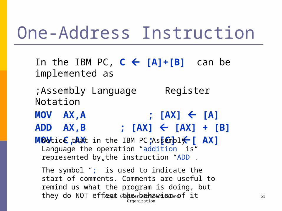
In the IBM PC, C [A]+[B] can be implemented as
;Assembly Language Register NotationMOV AX,A ; [AX] [A]ADD AX,B ; [AX] [AX] + [B]MOV C,AX ; [C] [ AX]
Notice that in the IBM PC Assembly Language the operation “addition” is represented by the instruction “ADD”.
The symbol “;” is used to indicate the start of comments. Comments are useful to remind us what the program is doing, but they do NOT effect the behavior of it
6155:035 Computer Architecture and Organization
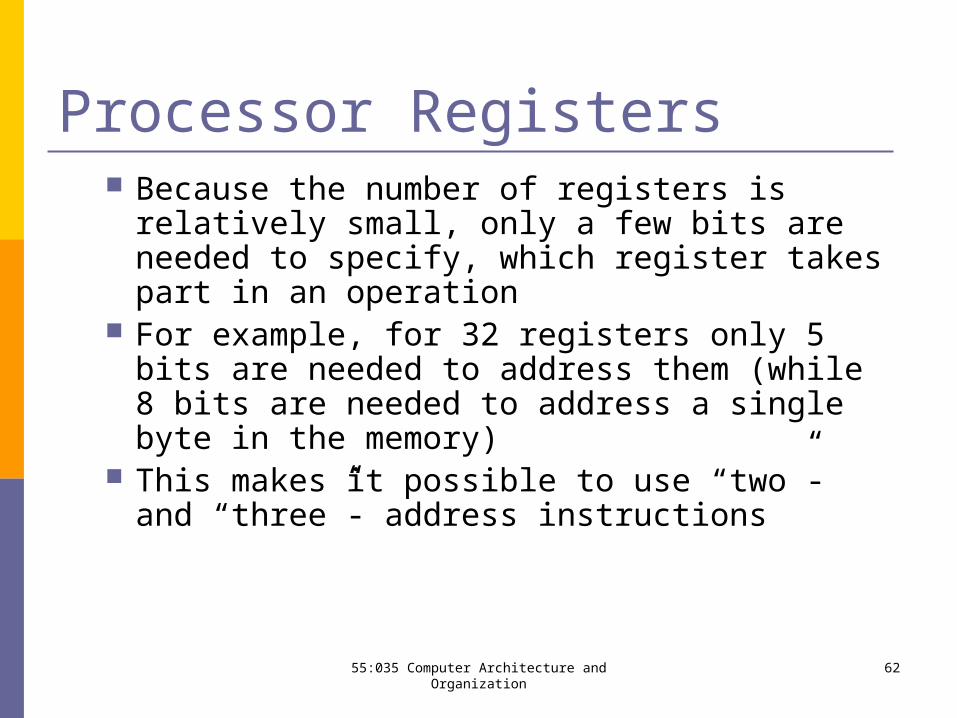
Processor Registers Because the number of registers is relatively small,
only a few bits are needed to specify, which register takes part in an operation
For example, for 32 registers only 5 bits are needed to address them (while 8 bits are needed to address a single byte in the memory)
This makes it possible to use “two”- and “three”- address instructions
6255:035 Computer Architecture and Organization
Using Processor Registers for Arithmetic Operations
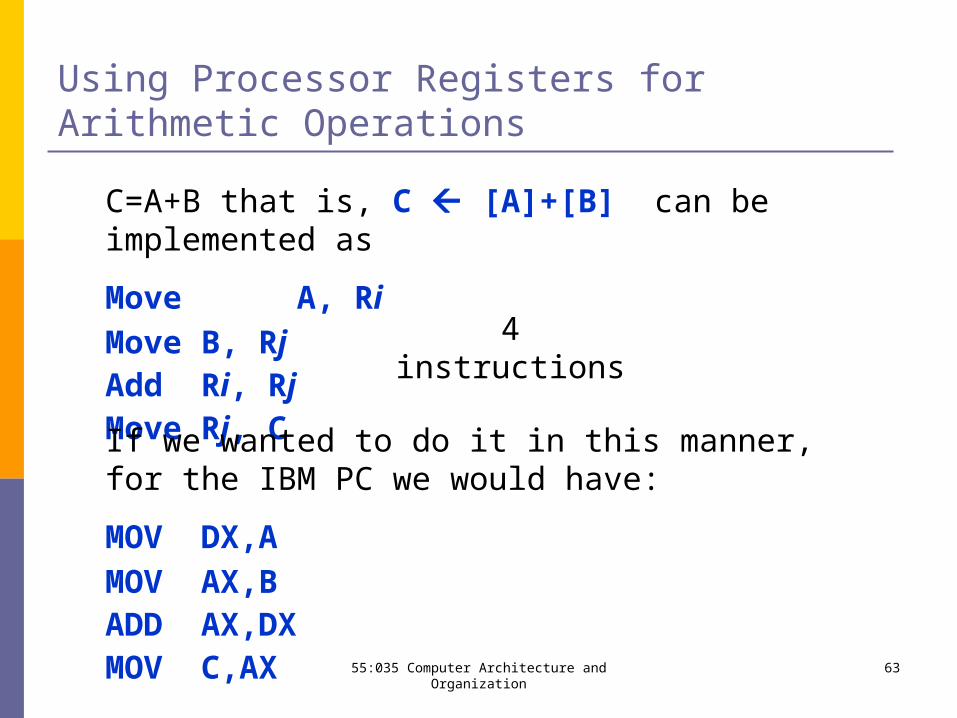
C=A+B that is, C [A]+[B] can be implemented as
Move A, RiMove B, RjAdd Ri, RjMove Rj, C
4 instructions
If we wanted to do it in this manner, for the IBM PC we would have:
MOV DX,AMOV AX,BADD AX,DXMOV C,AX 6355:035 Computer Architecture and Organization
If One of the Arithmetic Operands is in Memory
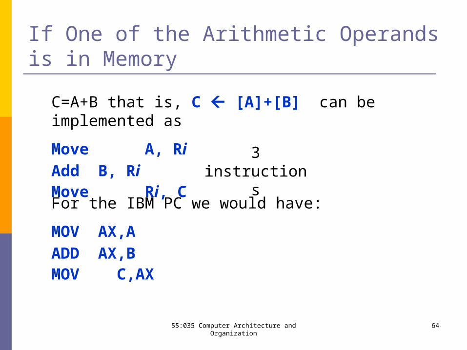
C=A+B that is, C [A]+[B] can be implemented as
Move A, RiAdd B, RiMove Ri, C
3 instructions
For the IBM PC we would have:
MOV AX,AADD AX,BMOV C,AX
6455:035 Computer Architecture and Organization
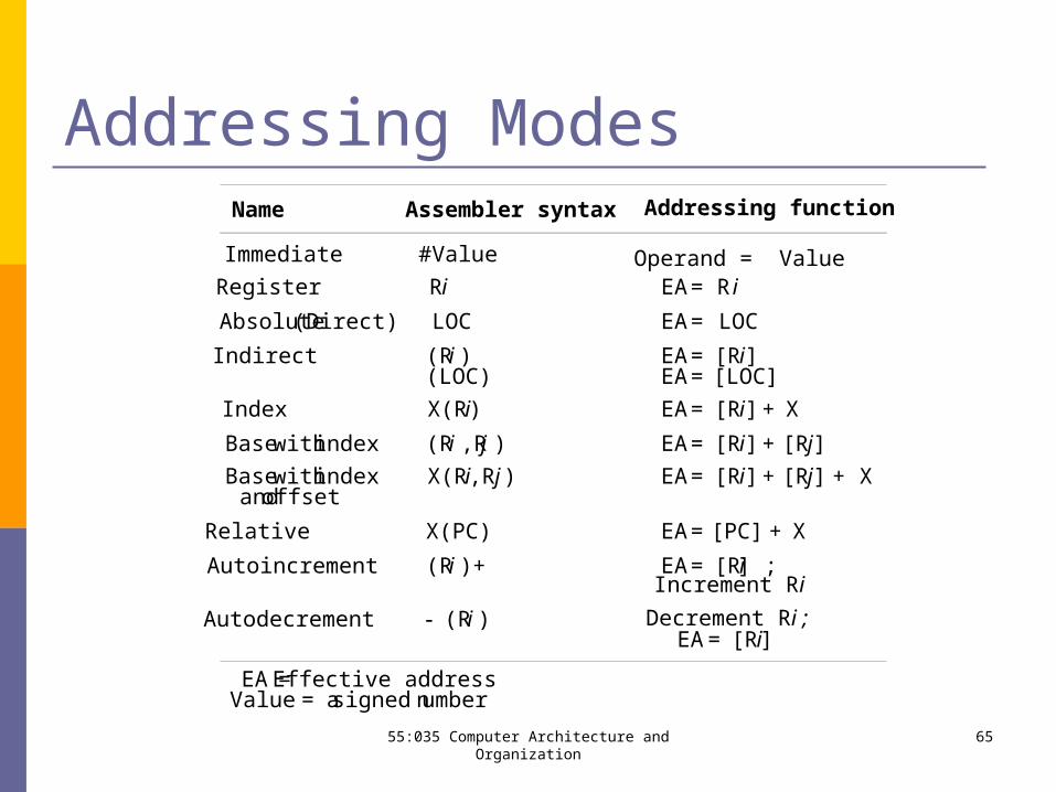
Addressing Modes
6555:035 Computer Architecture and Organization
Name Assembler syntax Addressing function
Immediate #Value Operand = ValueRegister Ri EA= Ri
Absolute(Direct) LOC EA= LOC
Indirect (Ri ) EA= [Ri](LOC) EA= [LOC]
Index X(Ri) EA= [Ri]+ X
Basewithindex (Ri ,Rj ) EA= [Ri]+ [Rj]
Basewithindex X(Ri,Rj ) EA= [Ri]+ [Rj] + Xandoffset
Relative X(PC) EA= [PC] + X
Autoincrement (Ri )+ EA= [Ri] ;Increment Ri
Autodecrement (Ri ) Decrement Ri ;EA= [Ri]
EA =Effective addressValue = asigned number
Program Sequencing and Control Programs aren’t all “in-line”, they also need to:
jump to and from subroutines loop branch to exception vectors etc
Use call and branch instructions Can be conditional
Branch > 0 LOOP
Control instruction examples cache control, pipeline control, RFI, WFI
6655:035 Computer Architecture and Organization
Specific Machine Levels
6755:035 Computer Architecture and Organization
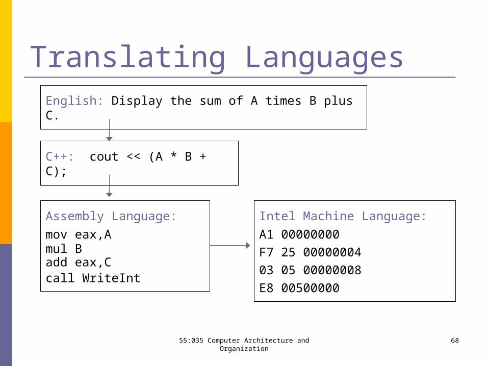
Translating LanguagesEnglish: Display the sum of A times B plus C.
C++: cout << (A * B + C);
Assembly Language:
mov eax,Amul Badd eax,Ccall WriteInt
Intel Machine Language:
A1 00000000
F7 25 00000004
03 05 00000008
E8 00500000
6855:035 Computer Architecture and Organization
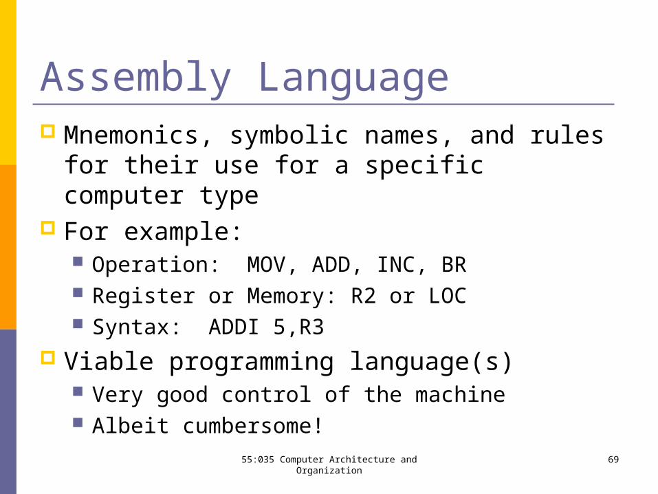
Assembly Language Mnemonics, symbolic names, and rules for their
use for a specific computer type For example:
Operation: MOV, ADD, INC, BR Register or Memory: R2 or LOC Syntax: ADDI 5,R3
Viable programming language(s) Very good control of the machine Albeit cumbersome!
6955:035 Computer Architecture and Organization
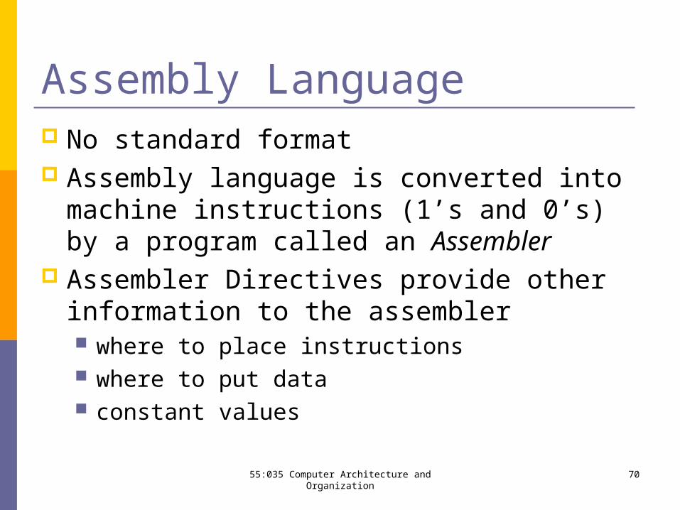
Assembly Language No standard format Assembly language is converted into machine
instructions (1’s and 0’s) by a program called an Assembler
Assembler Directives provide other information to the assembler where to place instructions where to put data constant values
7055:035 Computer Architecture and Organization
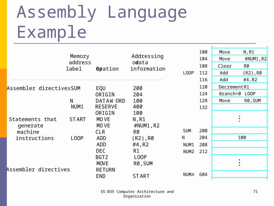
Assembly Language ExampleMemory Addressingaddress ordata
label Operation information
Assembler directives SUM EQU 200ORIGIN 204
N DATAWORD 100NUM1 RESERVE 400
ORIGIN 100Statements that START MOVE N,R1
generate MOVE #NUM1,R2machine CLR R0instructions LOOP ADD (R2),R0
ADD #4,R2DEC R1BGTZ LOOPMOVE R0,SUMRETURNEND START
Assembler directives
7155:035 Computer Architecture and Organization
NUM2
NUMn
NUM1
R0Clear
R0,SUM
R1
#4,R2
(R2),R0
100
132
604
212
208
204
200
128
124
120
116
112
108
104
100
SUM
N
LOOP
LOOP
Decrement
Add
Add
Move
#NUM1,R2
N,R1Move
Move
Branch>0
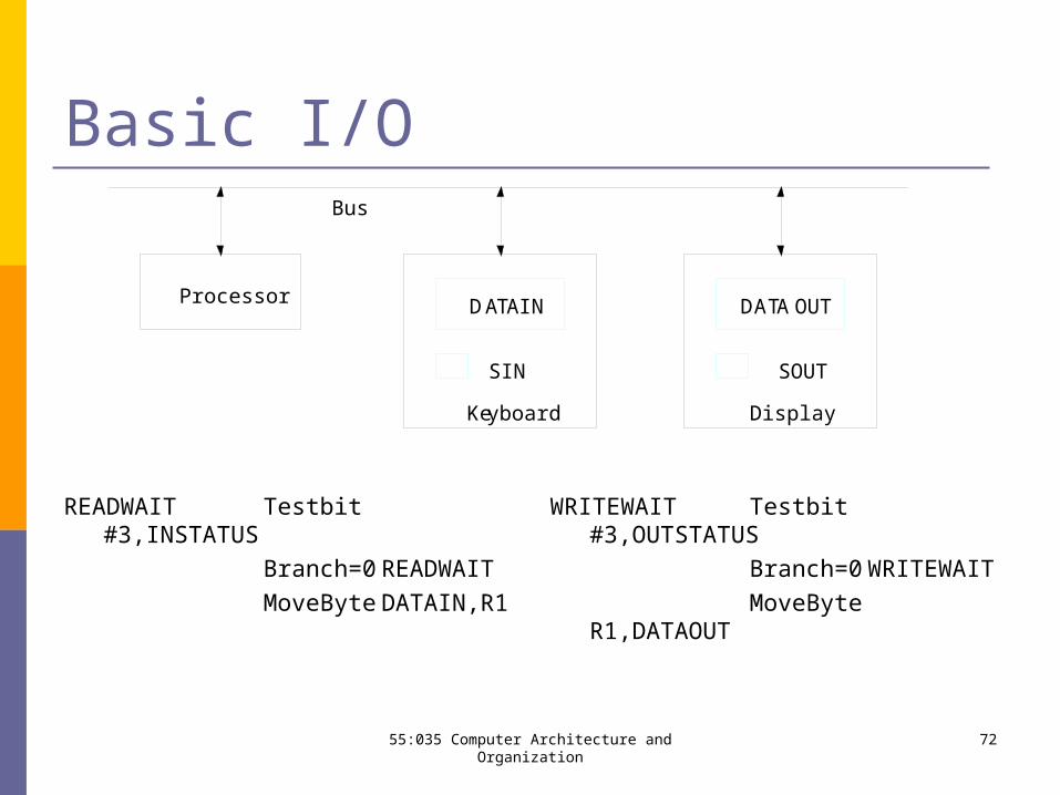
Basic I/O
READWAIT Testbit#3,INSTATUS
Branch=0 READWAIT
MoveByte DATAIN,R1
WRITEWAIT Testbit#3,OUTSTATUS
Branch=0 WRITEWAIT
MoveByteR1,DATAOUT
DATAIN DATAOUT
SIN SOUT
Ke yboard Display
Bus
Processor
7255:035 Computer Architecture and Organization
Queues / FIFOs First In — First Out
Buffer data between two entities: Keyboard => Processor Processor => Printer Processor1 => Processor2
Scheduling as well: Printer queue Queue of processes for multi-tasking Event queue in VerilogHDL
Queues may use priority ranking
55:035 Computer Architecture and Organization 73
Queues / FIFOs First In — First Out
The two basic functions are: APPEND an element on one end REMOVE an element from the other
Frequently, one entity appends items to the queue and another removes it
Two moving pointers are needed: IN: location for next APPEND OUT: location for next REMOVE
Wrap-around is needed
55:035 Computer Architecture and Organization 74
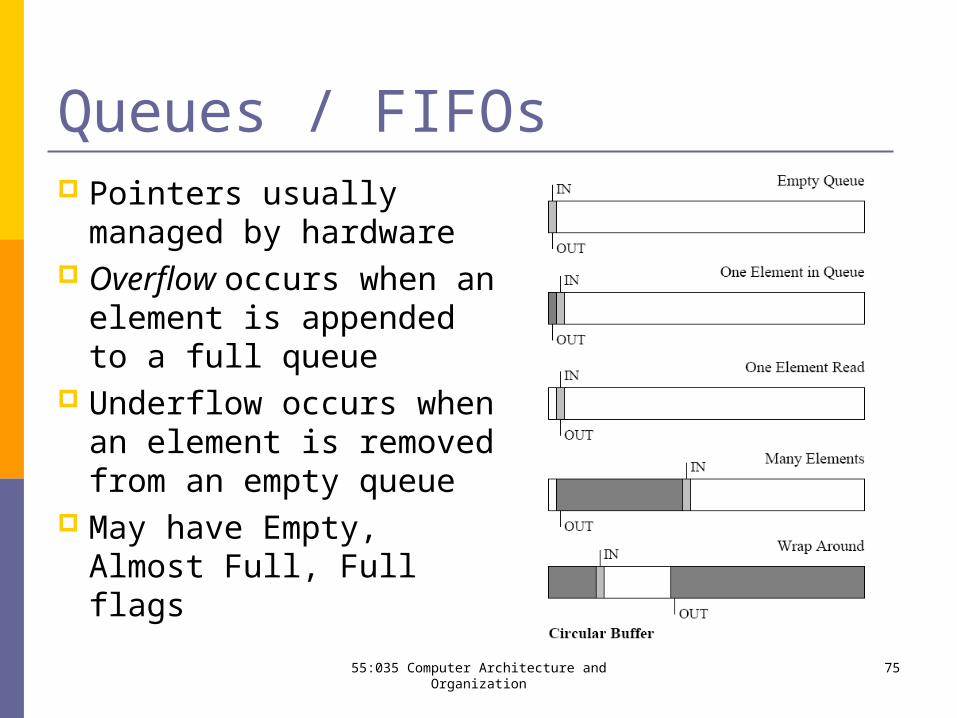
Queues / FIFOs Pointers usually
managed by hardware Overflow occurs when
an element is appended to a full queue
Underflow occurs when an element is removed from an empty queue
May have Empty, Almost Full, Full flags
55:035 Computer Architecture and Organization 75
Stacks/LIFOs Last In — First Out
Stacks are used to temporarily store items The two basic functions are:
PUSH an element on the top POP the top element from the stack
Frequently, the same entity that pushed the item on stack also pops it
In contrast to the queue Only one pointer needed – it points to the top element PUSH and POP in different directions Wrap-around is not needed
55:035 Computer Architecture and Organization 76
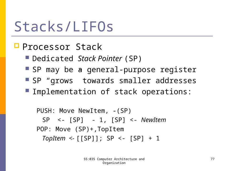
Stacks/LIFOs Processor Stack
Dedicated Stack Pointer (SP) SP may be a general-purpose register SP “grows” towards smaller addresses Implementation of stack operations:
PUSH: Move NewItem, -(SP)
SP <- [SP] - 1, [SP] <- NewItem
POP: Move (SP)+,TopItem
TopItem <- [[SP]]; SP <- [SP] + 1
55:035 Computer Architecture and Organization 77
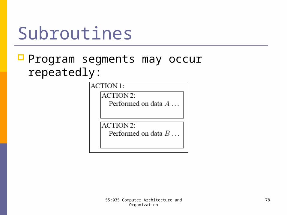
Subroutines Program segments may occur repeatedly:
55:035 Computer Architecture and Organization 78
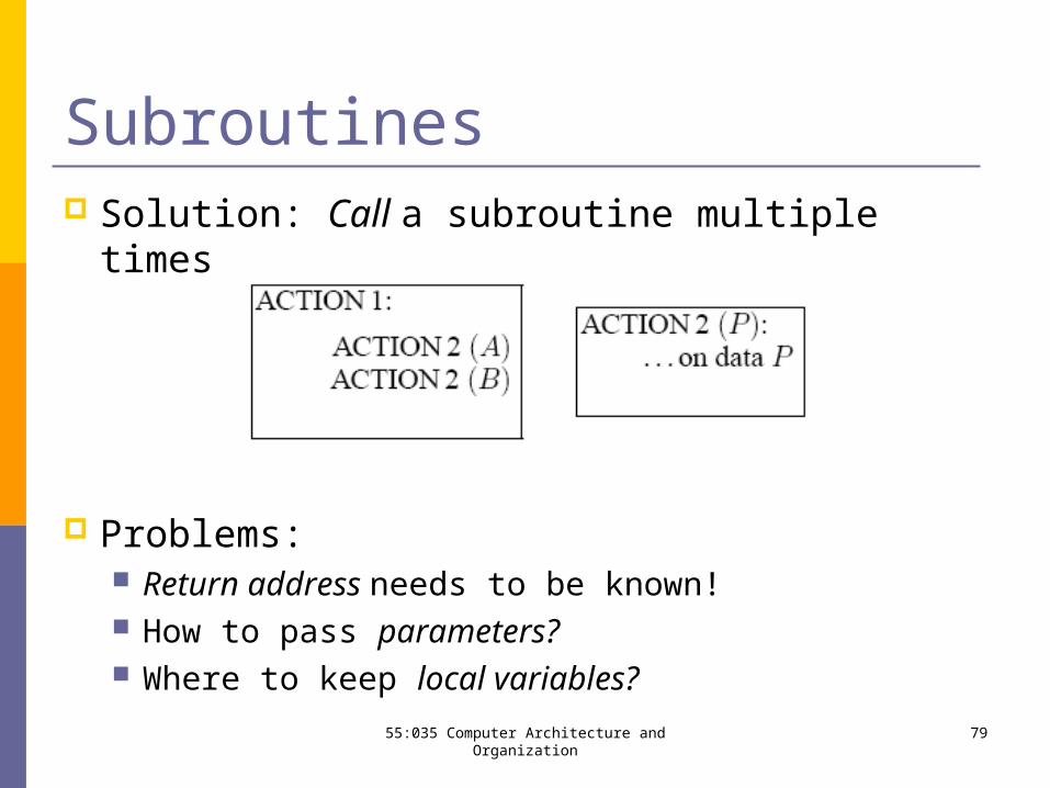
Subroutines Solution: Call a subroutine multiple times
Problems: Return address needs to be known! How to pass parameters? Where to keep local variables?
55:035 Computer Architecture and Organization 79
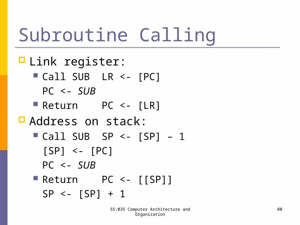
Subroutine Calling Link register:
Call SUB LR <- [PC]
PC <- SUB Return PC <- [LR]
Address on stack: Call SUB SP <- [SP] – 1
[SP] <- [PC]
PC <- SUB Return PC <- [[SP]]
SP <- [SP] + 155:035 Computer Architecture and Organization 80
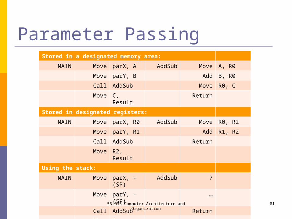
Parameter PassingStored in a designated memory area:
MAIN Move parX, A AddSub Move A, R0
Move parY, B Add B, R0
Call AddSub Move R0, C
Move C, Result Return
Stored in designated registers:
MAIN Move parX, R0 AddSub Move R0, R2
Move parY, R1 Add R1, R2
Call AddSub Return
Move R2, Result
Using the stack:
MAIN Move parX, -(SP) AddSub ?
Move parY, -(SP) …
Call AddSub Return
Move ?, Result
55:035 Computer Architecture and Organization 81
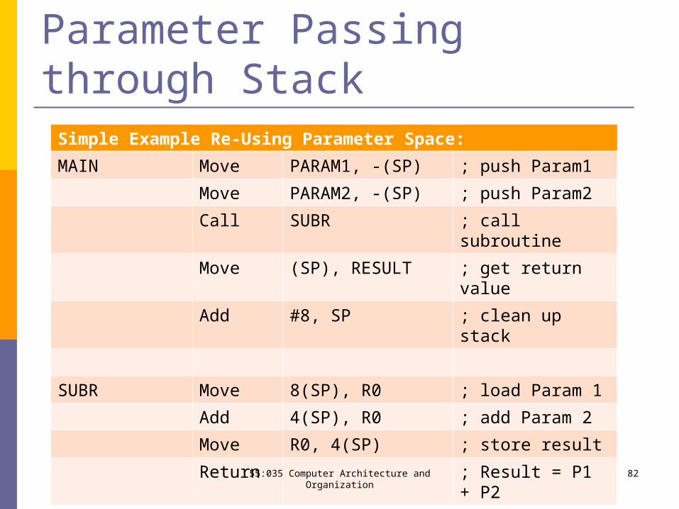
Parameter Passing through StackSimple Example Re-Using Parameter Space:
MAIN Move PARAM1, -(SP) ; push Param1
Move PARAM2, -(SP) ; push Param2
Call SUBR ; call subroutine
Move (SP), RESULT ; get return value
Add #8, SP ; clean up stack
SUBR Move 8(SP), R0 ; load Param 1
Add 4(SP), R0 ; add Param 2
Move R0, 4(SP) ; store result
Return ; Result = P1 + P2
55:035 Computer Architecture and Organization 82
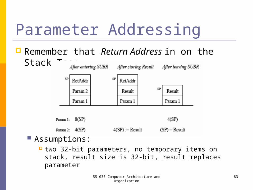
Parameter Addressing Remember that Return Address in on the Stack
Too:
Assumptions: two 32-bit parameters, no temporary items on stack, result
size is 32-bit, result replaces parameter
55:035 Computer Architecture and Organization 83
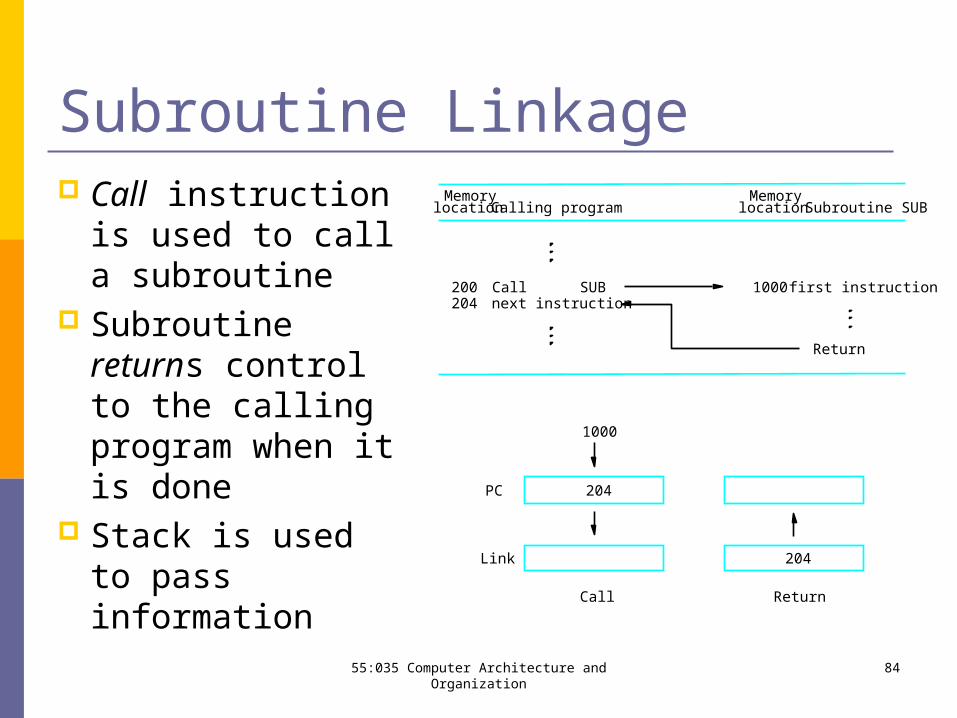
Subroutine Linkage Call instruction is
used to call a subroutine
Subroutine returns control to the calling program when it is done
Stack is used to pass information
ReturnCall
1000
204
204
Link
PC
Return
1000
locationMemory
Calling programMemorylocation
200204
Call SUBnext instruction
Subroutine SUB
first instruction
8455:035 Computer Architecture and Organization
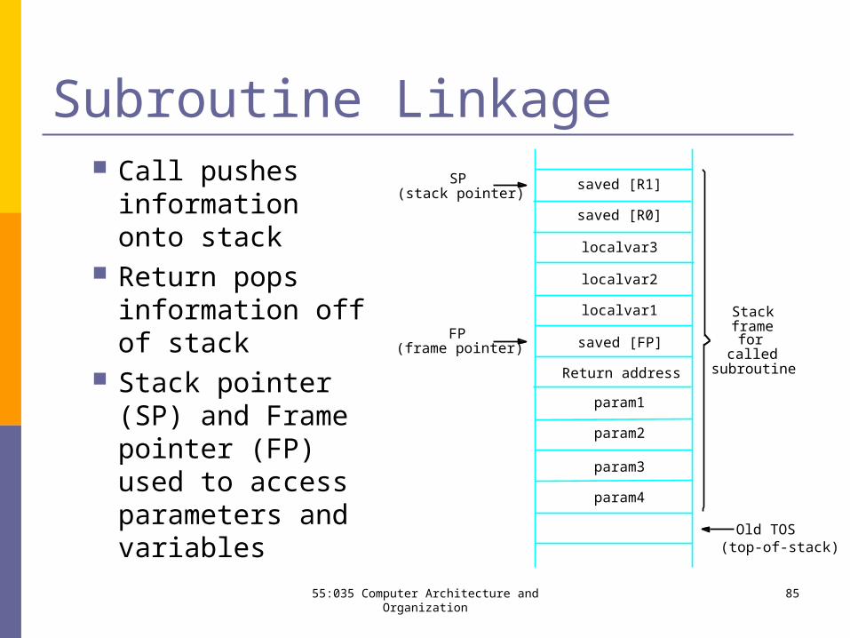
Subroutine Linkage Call pushes
information onto stack
Return pops information off of stack
Stack pointer (SP) and Frame pointer (FP) used to access parameters and variables
SP(stack pointer)
FP(frame pointer)
saved [R1]
saved [R0]
Stackframefor
calledsubroutineReturn address
localvar3
localvar2
localvar1
saved [FP]
Old TOS
param2
param1
param3
param4
(top-of-stack)
8555:035 Computer Architecture and Organization