Embed Size (px)
Citation preview
Alpha CP PropellerProduct Information
Contents
Introduction..................................................................................................3
General.Description.......................................................................................3
Propeller.equipment.................................................................................3
Propeller.type.VBS...................................................................................4
Mechanical.Design........................................................................................7
Hub.design..............................................................................................7
ODBox.Design.............................................................................................8
ODS.type................................................................................................8
ODF.type.................................................................................................9
ODG.type................................................................................................9
Servo.Oil.System.ODSODFODG............................................................... 10
Hydraulic.Power.Unit.(ODS..ODF)......................................................... 10
Hydraulic.system,.ODG.......................................................................... 11
Lubricating.oil.system,.VBS.................................................................... 11
Propeller.Shaft.and.Coupling.Flange............................................................ 12
Coupling.flange...................................................................................... 12
Stern.tube............................................................................................. 13
Liners.................................................................................................... 13
Seals..................................................................................................... 13
Hydraulic.bolts....................................................................................... 13
Installation............................................................................................. 13
Propeller.Blade.Manufacturing.and.Materials............................................... 14
Blade.materials...................................................................................... 14
Propeller.Nozzle.......................................................................................... 15
Nozzle.length......................................................................................... 16
Propeller.induced.pressure.impulses.and.nozzle.vibrations..................... 16
Optimizing.Propeller.Equipment................................................................... 17
Propeller.design..................................................................................... 17
Optimizing.the.complete.propulsion.plant............................................... 17
Hydrodynamic.design.of.propeller.blades............................................... 18
Cavitation.............................................................................................. 18
Technical.Calculation.and.Services.............................................................. 20
Arrangement.drawings........................................................................... 20
Installation.Manual................................................................................. 20
Alignment.instructions............................................................................ 21
Torsional.vibrations................................................................................ 21
Whirling.and.axial.vibration.calculations.................................................. 22
Instruction.Manual....................................................................................... 22
Main.Dimensions......................................................................................... 23
Propeller.Layout.Data.................................................................................. 25
MAN.Diesel.&.Turbo,.Frederikshavn,.Denmark

Alpha CP Propeller
Introduction
The. purpose. of. this. Product. Informa
tion.brochure. is. to.act.as.a.guide. in. the.
project.planning.of.MAN.Diesel.&.Turbo´s.
Alpha.propeller.equipment.
The. brochure. gives. a. description. of. the.
basic. design. principles. of. the. Alpha..
Controllable. Pitch. (CP). propeller.
equipment.. It. contains. dimensional.
sketches,. thereby. making. it. possible.
to.work.out.shaft.line.and.engine.room.
arrangement. drawings.. Furthermore,. a.
guideline. to.some.of.the.basic. layout.cri
teria.is.given.
Our.design.department.is.available.with.
assistance. for. optimization. of. propul
sion. efficiency. and. propeller. interac
tion. with. the. environment. it. works. in..
Prognises.are.performed.on.eg.speed.
and. bollard. pull,. determining. power..
requirements.from.the.propeller,.as.well.
as. advice. on. more. specific. questions.
like. installation. aspects. and. different.
modes.of.operation.
All.our.product.range.is.constantly.under.
review,.being.developed.and.improved.
as.needs.and.conditions.dictate.
We.therefore.reserve.the.right.to.make.
changes. to. the. technical. specification.
and.data.without.prior.notice.
In. connection. with. the. propeller. equip
ment. the.Alphatronic.Control. System. is.
applied..Special. literature.covering. this.
field.can.be.forwarded.on.request.
General Description
MAN. Diesel. &. Turbo. have. manufac
tured. more. than. 7,000. controllable.
pitch. propellers. of.which. the. first.was.
produced.in.1902.
In. 1903. a. patent. was. taken. out. cov
ering. the.principle.of. the.CP.propeller..
Thus.more.than.a.century.of.experience.
is.reflected.in.the.design.of.the.present..
Alpha.propeller.equipment.
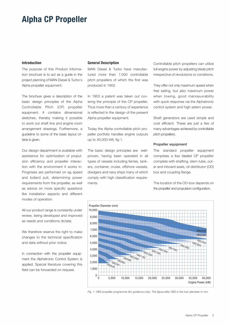
Today.the.Alpha.controllable.pitch.pro
peller.portfolio.handles.engine.outputs.
up.to.40,000.kW,.fig.1.
The. basic. design. principles. are. . well.
proven,. having. been. operated. in. all.
types.of.vessels.including.ferries,.tank
ers,.container,.cruise,.offshore.vessels,.
dredgers.and.navy.ships.many.of.which.
comply.with.high.classification.require
ments.
Controllable.pitch.propellers.can.utilize.
full.engine.power.by.adjusting.blade.pitch.
irrespective.of.revolutions.or.conditions.
They.offer.not.only.maximum.speed.when.
free. sailing,. but. also.maximum. power.
when. towing,. good. manoeuvrability.
with.quick.response.via.the.Alphatronic.
control.system.and.high.astern.power.
Shaft. generators. are. used. simple. and.
cost. efficient.. These. are. just. a. few. of.
many.advantages.achieved.by.controllable.
pitch.propellers.
Propeller equipment
The. standard. propeller. equipment.
comprises. a. four. bladed. CP. propeller.
complete.with.shafting,.stern.tube,.out
er.and.inboard.seals,.oil.distributor.(OD).
box.and.coupling.flange.
The.location.of.the.ODbox.depends.on..
the.propeller.and.propulsion.configuration.
Fig. 1: VBS propeller programme (for guidance only). The figure after VBS is the hub diameter in mm
10,000
10,000 15,000 25,000 30,000 35,000 40,00020,000
9,000
8,000
7,000
6,000
5,000
5,000
4,000
3,000
2,000
1,000
00
Propeller Diameter (mm)
Engine Power (kW)
VBS640
VBS740
VBS860
VBS980
VBS1080
VBS1180
VBS1280
VBS1380
VBS1460
VBS1560
VBS1680
VBS1800
VBS1940
VBS2080
VBS2240
3Alpha.CP.Propeller
Propeller type VBS
The. present. version. of. MAN. Diesel. &.
Turbo´s. Alpha. propeller. equipment. is.
designated.VBS..It.features.an.integrat
ed. servo.motor. located. in. the.aft. part.
of.the.hub.and.sturdy.designed.internal.
components.
A.welldistributed.range.of.different.hub.
sizes.makes.it.possible.to.select.an.op
timum.hub.for.any.given.combination.of.
power,. revolutions. and. ice. class.. The.
different.hub.sizes.are.in.principle.geo
Fig. 3: Propeller equipment type VBS ODS (7S60MCC engine, VBS1800 propeller, frontend PTO stepup gear and alternator)
Fig. 2: Propeller equipment type VBSODG (8L27/38 engine, AMG28EV reduction gear, VBS860 propeller)
metrical. similar. and. incorporate. large.
servo. piston. diameter. with. low. pres
sure.and.reaction.forces.and.few.com
ponents,. while. still. maintaining. short.
overall.installation.length.
Oil Distributor box
The.VBS.propeller.equipment.can.be.
supplied. with. three. different. oil. distri
bution.systems.for.controlling.the.pitch.
depending. on. the. type. of. propulsion.
system.i.e..direct.driven.twostroke.or.
geared. fourstroke.. All. three. types. in
corporate.the.possibility.for.emergency.
operation.and.a.valve.box.that.will.keep.
the.propeller.pitch.fixed.in.case.the.hy
draulic.oil.supply.is.interrupted..The.lat
ter. is. required. by. classification. societ
ies.and.will.prevent.the.propeller.blades.
from.changing.the.pitch.setting.
ODS Shaft mounted ODbox
For.direct.driven.propellers.without. re
duction. gearboxes. the. oil. distribution.
box.must.be.located.in.the.shaft.line..
4 Alpha.CP.Propeller
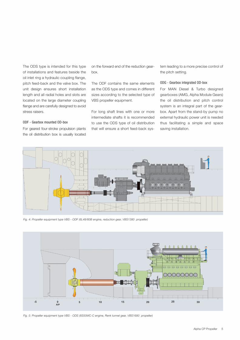
Fig. 4: Propeller equipment type VBS ODF (6L48/60B engine, reduction gear, VBS1380 propeller)
Fig. 5: Propeller equipment type VBS ODS (8S50MCC engine, Renk tunnel gear, VBS1680 propeller)
The.ODS.type.is.intended.for.this.type.
of. installations.and.features.beside.the.
oil.inlet.ring.a.hydraulic.coupling.flange,.
pitch.feedback.and.the.valve.box..The.
unit. design. ensures. short. installation.
length.and.all.radial.holes.and.slots.are.
located.on.the. large.diameter.coupling.
flange.and.are.carefully.designed.to.avoid.
stress.raisers.
ODF Gearbox mounted ODbox
For.geared. fourstroke.propulsion.plants.
the. oil. distribution. box. is. usually. located.
on.the.forward.end.of.the.reduction.gear
box.
The.ODF. contains. the. same. elements.
as.the.ODS.type.and.comes.in.different.
sizes.according.to.the.selected.type.of.
VBS.propeller.equipment.
For. long. shaft. lines. with. one. or. more.
intermediate.shafts. it. is. recommended.
to.use. the.ODS. type.of.oil.distribution.
that.will.ensure.a.short.feedback.sys
tem.leading.to.a.more.precise.control.of.
the.pitch.setting.
ODG Gearbox integrated ODbox
For. MAN. Diesel. &. Turbo. designed.
gearboxes.(AMG,.Alpha.Module.Gears).
the. oil. distribution. and. pitch. control.
system. is. an. integral. part. of. the.gear
box..Apart.from.the.standby.pump.no.
external.hydraulic.power.unit.is.needed.
thus. facilitating. a. simple. and. space.
saving.installation.
5Alpha.CP.Propeller
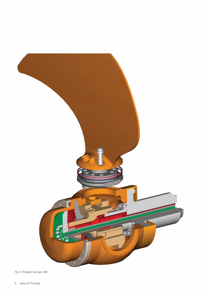
Fig. 6: Propeller hub type VBS
6 Alpha.CP.Propeller
Mechanical DesignHub design
The.hydraulic.servo.motor.for.pitch.set
ting. is.an. integral.part.of. the.propeller.
hub..The.design. is.shown. in. fig.6..The.
propeller.hub.is.bolted.to.the.flanged.end.
of.the.tailshaft,.which.is.hollow.bored.to.
accommodate. the. servo. oil. and. pitch.
feedback. tube.. The.servo.piston.which.
is.bolted.to.the.pitch.control.head,.forms.
the.hydraulic.servo.motor.together.with.
the.propeller.cap.
The.high.pressure.servo.oil.system.at.the.
aft.end.of.the.hub.is.completely.isolated.
from.the.pitch.regulating.mechanism.and.
thus.also. from. the.blade. flanges,.which.
means. that. the. blade. sealings. only. are.
subjected.to.gravitation.oil.pressure.
By.using.a.large.servo.piston.diameter.
and. balanced. blade. shapes,. the. oil.
pressure.and. reacting. forces.are.mini
mized.
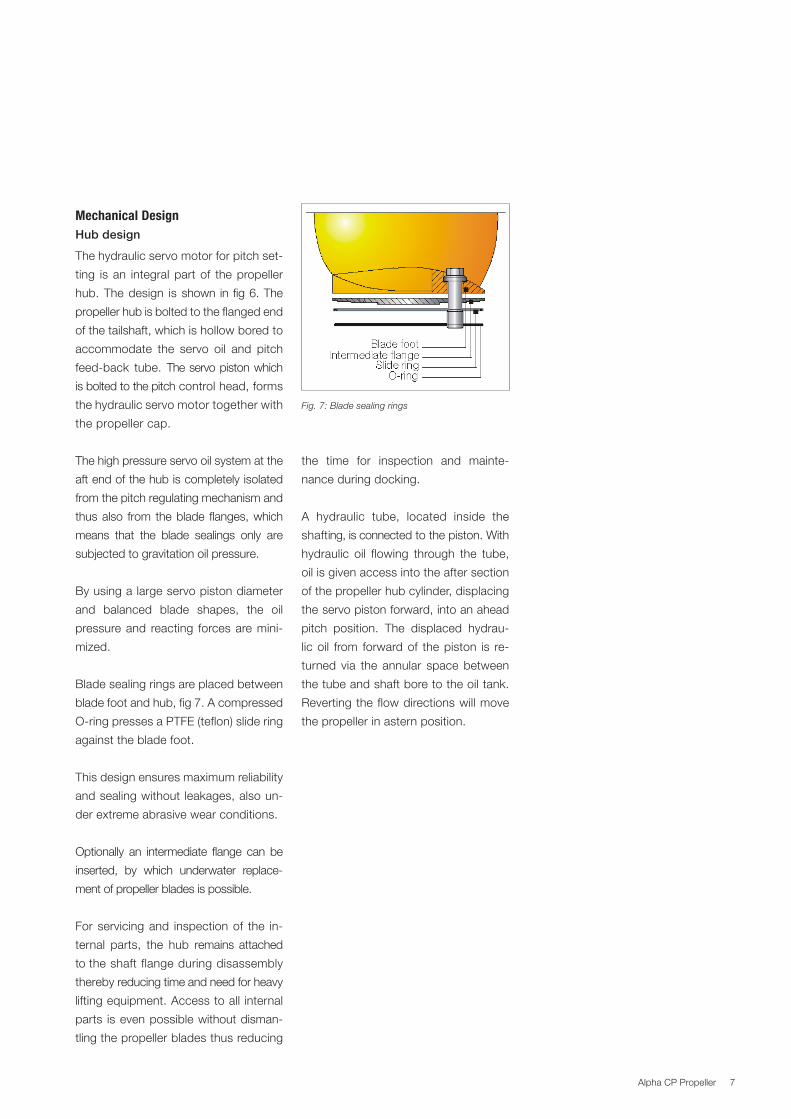
Blade.sealing.rings.are.placed.between.
blade.foot.and.hub,.fig.7..A.compressed.
Oring.presses.a.PTFE.(teflon).slide.ring.
against.the.blade.foot.
This.design.ensures.maximum.reliability.
and.sealing.without. leakages,.also.un
der.extreme.abrasive.wear.conditions..
Optionally. an. intermediate. flange. can. be.
inserted,. by. which. underwater. replace
ment.of.propeller.blades.is.possible..
For. servicing.and. inspection.of. the. in
ternal. parts,. the. hub. remains. attached.
to.the.shaft.flange.during.disassembly.
thereby.reducing.time.and.need.for.heavy.
lifting.equipment..Access.to.all. internal.
parts. is.even.possible.without.disman
tling.the.propeller.blades.thus.reducing.
Fig. 7: Blade sealing rings
the. time. for. inspection. and. mainte
nance.during.docking..
A. hydraulic. tube,. located. inside. the.
shafting,.is.connected.to.the.piston..With.
hydraulic. oil. flowing. through. the. tube,.
oil.is.given.access.into.the.after.section.
of.the.propeller.hub.cylinder,.displacing.
the.servo.piston.forward,.into.an.ahead.
pitch. position.. The. displaced. hydrau
lic.oil. from. forward.of. the.piston. is. re
turned. via. the. annular. space.between.
the.tube.and.shaft.bore.to.the.oil.tank..
Reverting.the. flow.directions.will.move.
the.propeller.in.astern.position.
7Alpha.CP.Propeller
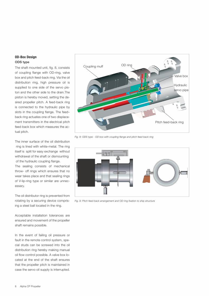
ODBox DesignODS type
The.shaft.mounted.unit,.fig..8,.consists.
of. coupling. flange.with. ODring,. valve.
box.and.pitch.feedback.ring..Via.the.oil..
distribution. ring,. high. pressure. oil. is.
supplied. to. one. side.of. the. servo.pis
ton.and.the.other.side.to.the.drain.The.
piston.is.hereby.moved,.setting.the.de
sired.propeller. pitch..A. feedback. ring.
is. connected. to. the. hydraulic. pipe. by.
slots. in. the.coupling. flange..The. feed–
back.ring.actuates.one.of.two.displace
ment.transmitters.in.the.electrical.pitch.
feedback.box.which.measures.the.ac
tual.pitch.
The.inner.surface.of.the.oil.distribution.
.ring.is.lined.with.whitemetal..The.ring.
itself.is..split.for.easy.exchange..without.
withdrawal.of.the.shaft.or.dismounting
.of.the.hydraulic.coupling.flange.
The. sealing. consists. of. mechanical.
throw.off. rings.which.ensures. that.no.
wear.takes.place.and.that.sealing.rings.
of.Vlipring. type.or. similar. are.unnec
essary.
The.oil.distributor.ring.is.prevented.from.
rotating.by.a.securing.device.compris
ing.a.steel.ball.located.in.the.ring..
Acceptable. installation. tolerances. are.
ensured.and.movement.of.the.propeller.
shaft.remains.possible.
In. the. event. of. failing. oil. pressure. or.
fault.in.the.remote.control.system,.spe
cial. studs. can.be. screwed. into. the. oil.
distribution.ring.hereby.making.manual.
oil.flow.control.possible..A.valve.box.lo
cated. at. the. end. of. the. shaft. ensures.
that.the.propeller.pitch.is.maintained.in.
case.the.servo.oil.supply.is.interrupted.
Fig. 8: ODS type OD box with coupling flange and pitch feedback ring
..OD.ring..Coupling.muff
..Valve.box
Pitch.feedback.ring
Hydraulic
servo.pipe
Fig. 9: Pitch feedback arrangement and OD ring fixation to ship structure
8 Alpha.CP.Propeller
9
Fig. 10: ODG type – integrated in Alpha Mudule Gearboxes
Fig. 9: ODF type – for gearbox mounting
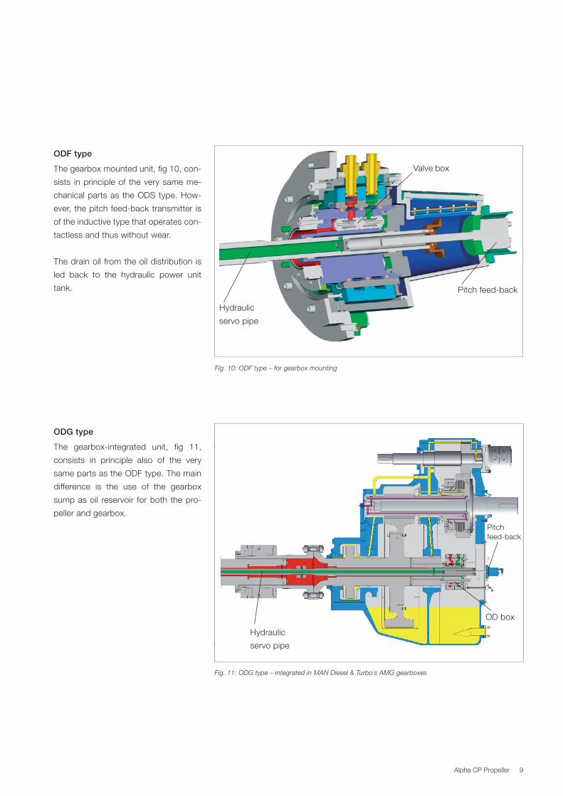
ODF type
The.gearbox.mounted.unit,.fig.10,.con
sists. in.principle.of. the.very.same.me
chanical.parts.as. the.ODS.type..How
ever,.the.pitch.feedback.transmitter.is.
of.the.inductive.type.that.operates.con
tactless.and.thus.without.wear.
The.drain.oil. from.the.oil.distribution. is.
led. back. to. the. hydraulic. power. unit.
tank.
Fig. 11: ODG type – integrated in MAN Diesel & Turbo´s AMG gearboxes
Fig. 10: ODF type – for gearbox mounting
.OD.box
Hydraulic
servo.pipe
Pitch.feedback
Pitch.feedback
..Valve.box
Hydraulic
servo.pipe
ODG type
The. gearboxintegrated. unit,. fig. 11,.
consists. in. principle. also. of. the. very.
same.parts.as.the.ODF.type..The.main.
difference. is. the. use. of. the. gearbox.
sump.as.oil. reservoir. for.both.the.pro
peller.and.gearbox.
9Alpha.CP.Propeller
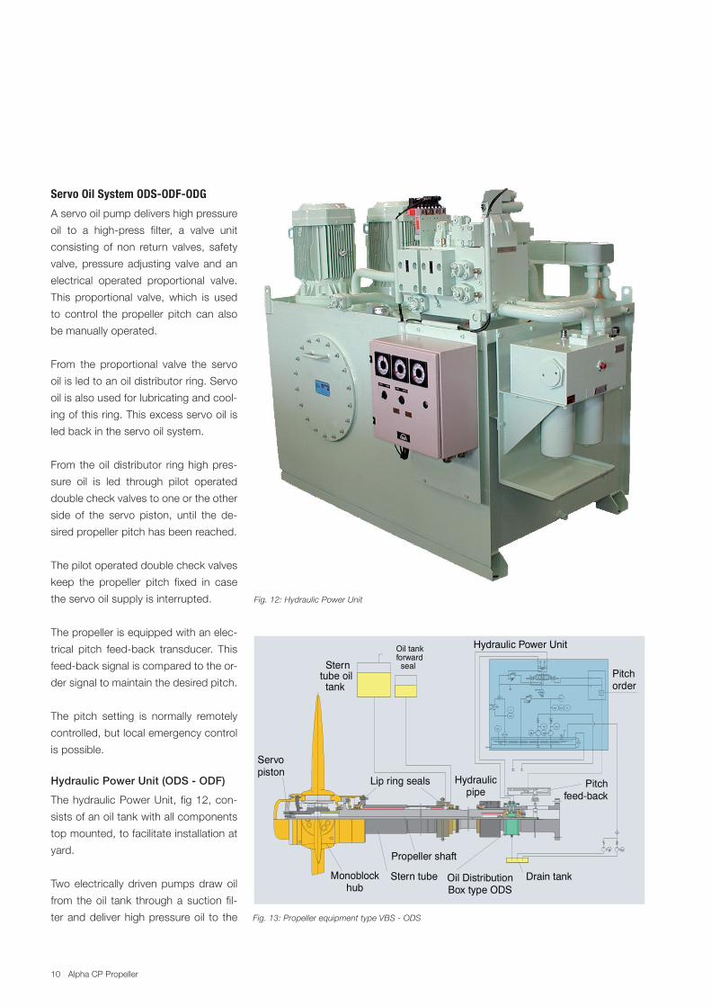
Servo Oil System ODSODFODG
A.servo.oil.pump.delivers.high.pressure.
oil. to. a. highpress. filter,. a. valve. unit.
consisting. of. non. return. valves,. safety.
valve,.pressure.adjusting.valve.and.an.
electrical. operated. proportional. valve..
This. proportional. valve,. which. is. used.
to. control. the. propeller. pitch. can. also.
be.manually.operated.
From. the. proportional. valve. the. servo.
oil.is.led.to.an.oil.distributor.ring..Servo.
oil.is.also.used.for.lubricating.and.cool
ing.of.this.ring..This.excess.servo.oil.is.
led.back.in.the.servo.oil.system.
From. the.oil.distributor. ring.high.pres
sure. oil. is. led. through. pilot. operated.
double.check.valves.to.one.or.the.other.
side. of. the. servo. piston,. until. the. de
sired.propeller.pitch.has.been.reached..
The.pilot.operated.double.check.valves.
keep. the. propeller. pitch. fixed. in. case.
the.servo.oil.supply.is.interrupted.
The.propeller.is.equipped.with.an.elec
trical. pitch. feedback. transducer.. This.
feedback.signal.is.compared.to.the.or
der.signal.to.maintain.the.desired.pitch.
The. pitch. setting. is. normally. remotely.
controlled,.but.local.emergency.control.
is.possible.
Hydraulic Power Unit (ODS ODF)
The.hydraulic.Power.Unit,. fig.12,.con
sists.of.an.oil.tank.with.all.components.
top.mounted,.to.facilitate.installation.at.
yard.
Two.electrically.driven.pumps.draw.oil.
from. the.oil. tank. through.a.suction. fil
ter.and.deliver.high.pressure.oil. to. the. Fig. 13: Propeller equipment type VBS ODS
Fig. 12: Hydraulic Power Unit
M M
PD
LAL
TAH
TIPAH
PSL
M M
PSL
PAL PI
PAL
Pitchorder
Drain tankOil Distribution Box type ODS
Stern tubeMonoblock hub
Oil tankforward seal Stern
tube oil tank
Lip ring seals Hydraulicpipe
Propeller shaft
Hydraulic Power Unit
Servopiston
Pitchfeed-back
10 Alpha.CP.Propeller
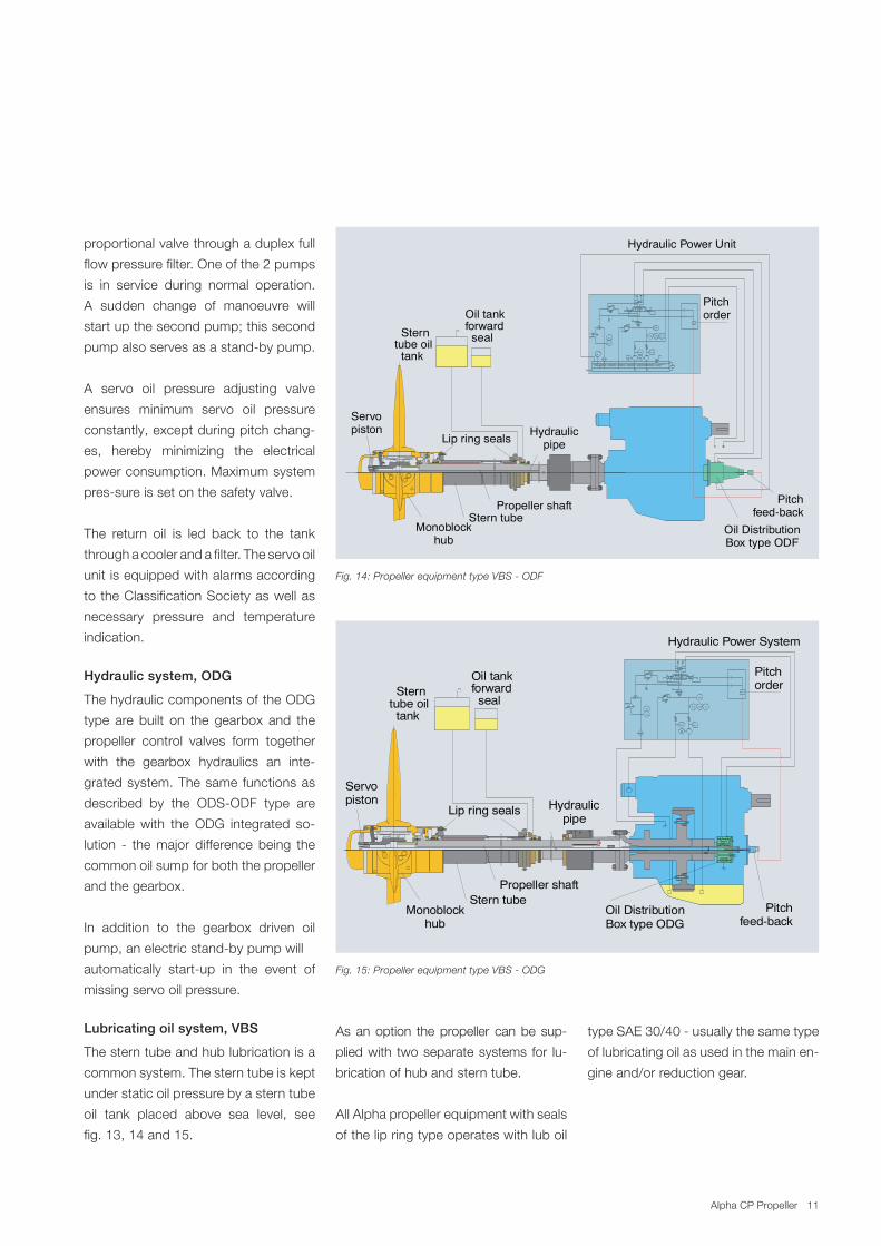
Fig. 14: Propeller equipment type VBS ODF
Fig. 15: Propeller equipment type VBS ODG
proportional.valve.through.a.duplex.full.
flow.pressure.filter..One.of.the.2.pumps.
is. in. service. during. normal. operation..
A. sudden. change. of. manoeuvre. will.
start.up.the.second.pump;.this.second.
pump.also.serves.as.a.standby.pump..
.
A. servo. oil. pressure. adjusting. valve.
ensures. minimum. servo. oil. pressure.
constantly,.except.during.pitch.chang
es,. hereby. minimizing. the. electrical.
power.consumption..Maximum.system.
pressure.is.set.on.the.safety.valve.
The. return. oil. is. led. back. to. the. tank.
through.a.cooler.and.a.filter..The.servo.oil.
unit.is.equipped.with.alarms.according..
to.the.Classification.Society.as.well.as.
necessary. pressure. and. temperature..
indication.
Hydraulic system, ODG
The.hydraulic.components.of.the.ODG.
type. are. built. on. the. gearbox. and. the.
propeller. control. valves. form. together.
with. the. gearbox. hydraulics. an. inte
grated.system..The.same.functions.as.
described. by. the. ODSODF. type. are.
available.with. the.ODG. integrated. so
lution. . the.major. difference.being. the.
common.oil.sump.for.both.the.propeller.
and.the.gearbox.
In. addition. to. the. gearbox. driven. oil.
pump,.an.electric.standby.pump.will
automatically. startup. in. the. event. of.
missing.servo.oil.pressure.
Lubricating oil system, VBS
The.stern.tube.and.hub.lubrication.is.a.
common.system..The.stern.tube.is.kept.
under.static.oil.pressure.by.a.stern.tube.
oil. tank. placed. above. sea. level,. see..
fig..13,.14.and.15.
11
TAH
L AL
PD
PAL
P SL
M
T I
M
P SL
PI
PAL
PAH
Pitchorder
Pitchfeed-back
Oil Distribution Box type ODF
Stern tubeMonoblock
hub
Oil tankforward seal Stern
tube oil tank
Lip ring seals
Servopiston Hydraulic
pipe
Propeller shaft
Hydraulic Power Unit
TAH
T I
PS L PS L
M
P AL PI
PAL
PAH
P D
Pitchfeed-back
Oil Distribution Box type ODG
Stern tubeMonoblock
hub
Oil tankforward seal
Sterntube oil tank
Lip ring seals
Servopiston Hydraulic
pipe
Propeller shaft
Hydraulic Power System
Pitchorder
As.an.option. the.propeller. can.be. sup
plied.with. two.separate.systems. for. lu
brication.of.hub.and.stern.tube.
All.Alpha.propeller.equipment.with.seals.
of.the.lip.ring.type.operates.with.lub.oil.
type.SAE.30/40..usually.the.same.type.
of.lubricating.oil.as.used.in.the.main.en
gine.and/or.reduction.gear. 11
TAH
L AL
PD
PAL
P SL
M
T I
M
P SL
PI
PAL
PAH
Pitchorder
Pitchfeed-back
Oil Distribution Box type ODF
Stern tubeMonoblock
hub
Oil tankforward seal Stern
tube oil tank
Lip ring seals
Servopiston Hydraulic
pipe
Propeller shaft
Hydraulic Power Unit
TAH
T I
PS L PS L
M
P AL PI
PAL
PAH
P D
Pitchfeed-back
Oil Distribution Box type ODG
Stern tubeMonoblock
hub
Oil tankforward seal
Sterntube oil tank
Lip ring seals
Servopiston Hydraulic
pipe
Propeller shaft
Hydraulic Power System
Pitchorder
11Alpha.CP.Propeller
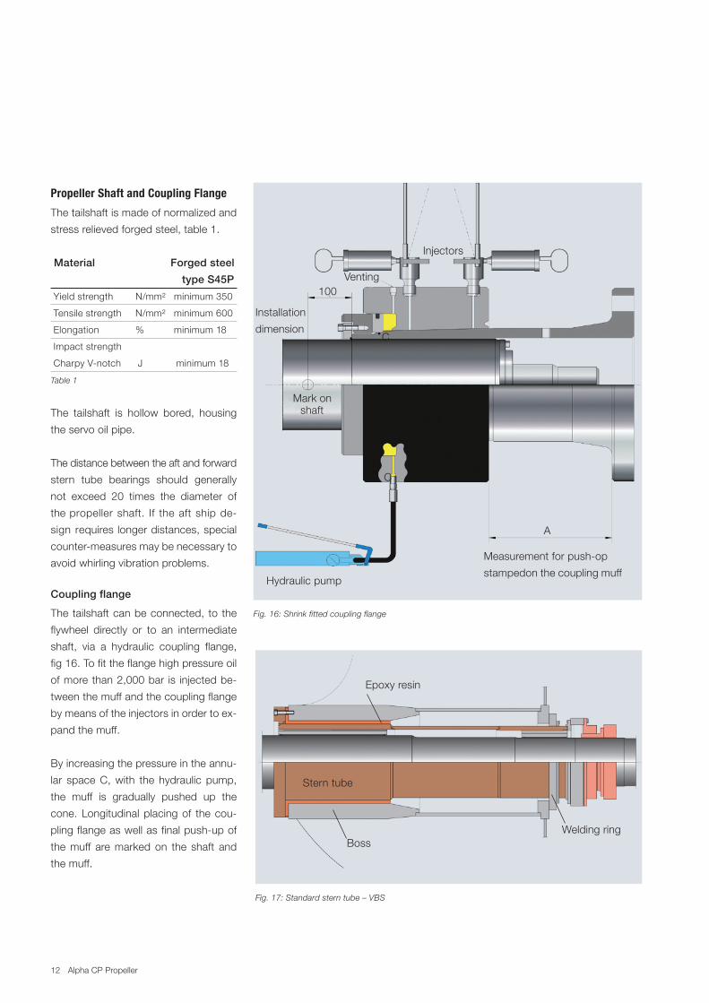
Fig. 16: Shrink fitted coupling flange
Fig. 17: Standard stern tube – VBS
Propeller Shaft and Coupling Flange
The.tailshaft.is.made.of.normalized.and.
stress.relieved.forged.steel,.table.1.
Material Forged steel
type S45P
.Yield.strength.........N/mm²....minimum.350.
.Tensile.strength.....N/mm²....minimum.600.
.Elongation...............%............minimum.18.
.Impact.strength..
.Charpy.Vnotch........J.............minimum.18.
Table 1
The. tailshaft. is. hollow. bored,. housing.
the.servo.oil.pipe.
The.distance.between.the.aft.and.forward.
stern. tube. bearings. should. generally.
not. exceed. 20. times. the. diameter. of.
the.propeller.shaft.. If. the.aft.ship.de
sign. requires. longer.distances,.special.
countermeasures.may.be.necessary.to.
avoid.whirling.vibration.problems.
Coupling flange
The.tailshaft.can.be.connected,. to. the.
flywheel. directly. or. to. an. intermediate.
shaft,. via. a. hydraulic. coupling. flange,.
fig.16..To.fit.the.flange.high.pressure.oil.
of.more.than.2,000.bar. is. injected.be
tween.the.muff.and.the.coupling.flange.
by.means.of.the.injectors.in.order.to.ex
pand.the.muff..
By.increasing.the.pressure.in.the.annu
lar. space.C,.with. the. hydraulic. pump,.
the. muff. is. gradually. pushed. up. the.
cone..Longitudinal.placing.of. the.cou
pling.flange.as.well.as.final.pushup.of.
the.muff. are.marked.on. the. shaft. and.
the.muff..
Stern.tube
Welding.ringBoss
Measurement.for.pushop
stampedon.the.coupling.muff...Hydraulic.pump
Installation
dimension
100
...Injectors
Venting
A
C
C
...Mark.on
.....shaft
Epoxy.resin
12 Alpha.CP.Propeller
Stern tube
Many. different. installation. and. stern.
tube.alternatives.exist. for.both.oil. and.
water. lubrication.. The. standard. stern.
tube. is. designed. to. be. fitted. from. aft.
and.installed.with.epoxy.resin.and.bolt
ed.to.the.stern.frame.boss,.fig.17.
The. forward. end. of. the. stern. tube. is.
supported.by.the.welding.ring..
The. oilbox. and. the. forward. shaft. seal.
are. bolted. onto. the.welding. ring.. This.
design. allows. thermal. expansion/con
traction.of.the.stern.tube.and.decreas
es.the.necessity.for.close.tolerances.of.
the.stern.tube.installation.length.
As.an.option.the.stern.tube.can.be.in
stalled.with.a.pressfitting.and.bolted.to.
the.stern.frame.boss..The.stern.tube.is.
then.supplied.with.5.mm.machining.al
lowance.for.yard.finishing.
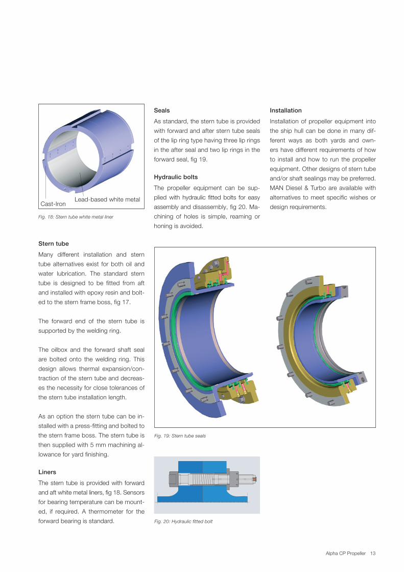
Liners
The.stern. tube. is.provided.with. forward.
and.aft.white.metal.liners,.fig.18..Sensors.
for.bearing.temperature.can.be.mount
ed,. if. required.. A. thermometer. for. the.
forward.bearing.is.standard.
Fig. 18: Stern tube white metal liner
Fig. 20: Hydraulic fitted bolt
Fig. 19: Stern tube seals
Seals
As.standard,.the.stern.tube.is.provided.
with.forward.and.after.stern.tube.seals.
of.the.lip.ring.type.having.three.lip.rings.
in.the.after.seal.and.two.lip.rings.in.the.
forward.seal,.fig.19.
Hydraulic bolts
The. propeller. equipment. can. be. sup
plied.with. hydraulic. fitted.bolts. for. easy.
assembly.and.disassembly,.fig.20..Ma
chining. of. holes. is. simple,. reaming. or.
honing.is.avoided.
Leadbased.white.metalCastIron..
Installation
Installation.of.propeller.equipment. into.
the.ship.hull.can.be.done. in.many.dif
ferent. ways. as. both. yards. and. own
ers.have.different.requirements.of.how.
to. install. and.how. to. run. the.propeller.
equipment..Other.designs.of.stern.tube.
and/or.shaft.sealings.may.be.preferred..
MAN.Diesel.&.Turbo.are.available.with.
alternatives. to.meet.specific.wishes.or.
design.requirements.
13
13Alpha.CP.Propeller
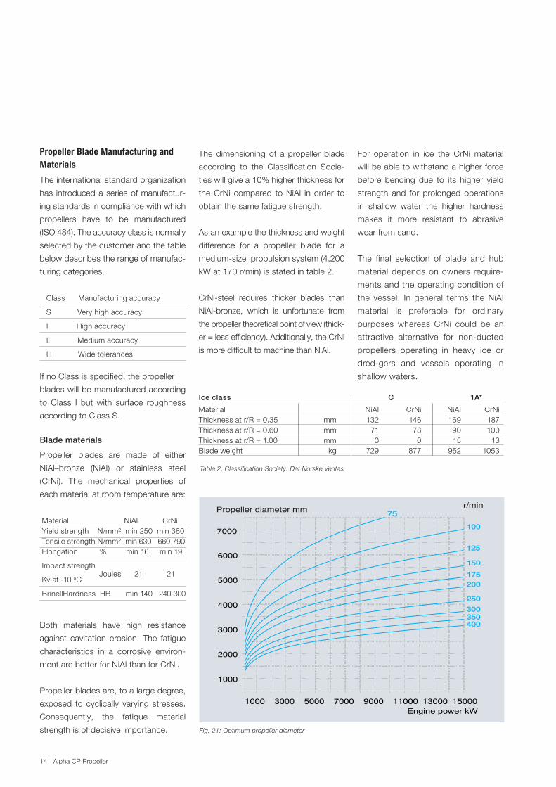
Table 2: Classification Society: Det Norske Veritas
Ice class C 1A*
Material.... . . ...NiAl.. ..........CrNi.. ..NiAl.. .....CrNi.Thickness.at.r/R.=.0.35.. .. mm... ...132.. ..........146.. ..169.. ......187.Thickness.at.r/R.=.0.60.. . .mm.. .....71.. ............78. ....90.. ......100.Thickness.at.r/R.=.1.00.. .. mm.. .......0.. ..............0.. ....15.. ........13Blade.weight.. . ..kg.. ...729.. ..........877.. ..952.. ....1053
Propeller Blade Manufacturing and Materials
The.international.standard.organization.
has. introduced.a.series.of.manufactur
ing.standards.in.compliance.with.which.
propellers. have. to. be. manufactured.
(ISO.484)..The.accuracy.class.is.normally.
selected.by.the.customer.and.the.table.
below.describes.the.range.of.manufac
turing.categories.
...Class........Manufacturing.accuracy.
...S..............Very.high.accuracy.
...I..............High.accuracy.
...II.. .Medium.accuracy.
...III.............Wide.tolerances.
If.no.Class.is.specified,.the.propeller.
blades.will.be.manufactured.according.
to.Class. I. but.with. surface. roughness.
according.to.Class.S.
Blade materials
Propeller. blades. are. made. of. either.
NiAl–bronze. (NiAl). or. stainless. steel.
(CrNi).. The. mechanical. properties. of.
each.material.at.room.temperature.are:
.Material.. NiAl.... CrNi.
.Yield.strength.....N/mm²...min.250..min.380.
.Tensile.strength..N/mm²...min.630....660790.
.Elongation............%..........min.16......min.19.
.Impact.strength.
..Kv.at.10..oC........Joules.......21............21.
.Brinell.Hardness....HB........min.140....240300.
Both. materials. have. high. resistance.
against. cavitation. erosion.. The. fatigue.
characteristics. in. a. corrosive. environ
ment.are.better.for.NiAl.than.for.CrNi.
Propeller.blades.are,.to.a.large.degree,.
exposed. to. cyclically. varying. stresses..
Consequently,. the. fatique. material.
strength.is.of.decisive.importance. Fig. 21: Optimum propeller diameter
The. dimensioning. of. a. propeller. blade.
according. to. the. Classification. Socie
ties.will.give.a.10%.higher.thickness.for.
the.CrNi. compared. to.NiAl. in.order. to.
obtain.the.same.fatigue.strength.
As.an.example.the.thickness.and.weight.
difference. for. a. propeller. blade. for. a.
mediumsize..propulsion.system.(4,200.
kW.at.170.r/min).is.stated.in.table.2.
CrNisteel. requires. thicker. blades. than.
NiAlbronze,. which. is. unfortunate. from.
the.propeller.theoretical.point.of.view.(thick
er.=.less.efficiency)..Additionally,.the.CrNi.
is.more.difficult.to.machine.than.NiAl.
For. operation. in. ice. the. CrNi. material.
will.be.able.to.withstand.a.higher.force.
before. bending. due. to. its. higher. yield.
strength. and. for. prolonged.operations.
in. shallow. water. the. higher. hardness.
makes. it. more. resistant. to. abrasive.
wear.from.sand.
The. final. selection. of. blade. and. hub.
material.depends.on.owners. require
ments.and.the.operating.condition.of.
the. vessel.. In. general. terms. the.NiAl.
material. is. preferable. for. ordinary.
purposes. whereas. CrNi. could. be. an.
attractive. alternative. for. nonducted.
propellers. operating. in. heavy. ice. or.
dredgers. and. vessels. operating. in.
shallow.waters.
1000 3000 5000 7000 9000 11000 13000 15000
1000
2000
3000
4000
5000
6000
7000
Engine power kW
75
100
125
150
175200
250
300350400
Propeller diameter mm r/min
14 Alpha.CP.Propeller
Propeller Nozzle
Typical.offshore.vessels,.tugs.and.trawl
ers. are. equipped.with. nozzles. around.
their. propellers. to. increase. the.bollard.
pull. and. the. pull. at. low. ship. speeds..
Maximising. the. bollard. pull. has. up. to.
now.primarily.been.a.matter.of.having.
sufficient. power. installed. with. little. at
tention.paid.to.the.efficiency.of.the.pro
pulsion.system.in.particular.the.propel
ler.and.its.nozzle...
Especially. the. nozzle. ‘type. 19A’. de
veloped. by. Wageningen. model. basin.
in. the.Nederlands. has. for.many. years.
been. universally. used. for. all. sorts. of.
vessels,. partly. due. to. its. production.
friendly.design..To.less.extent.the.‘type.
37’.nozzle.is.used,.normally.where.high.
astern.thrust.is.required.
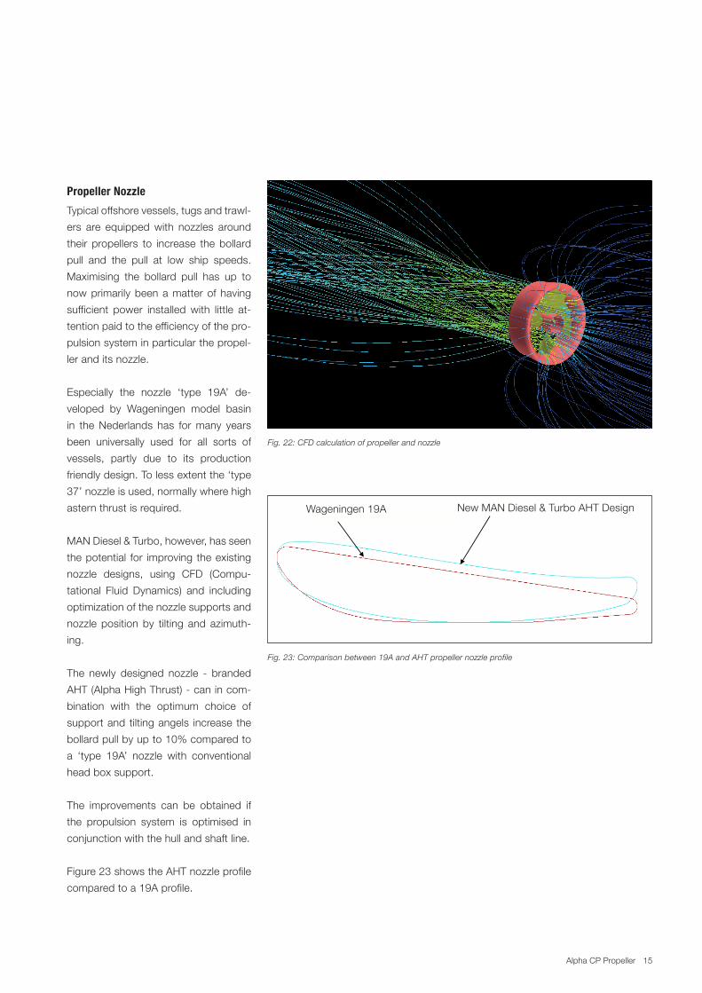
MAN.Diesel.&.Turbo,.however,.has.seen.
the.potential. for. improving.the.existing.
nozzle. designs,. using. CFD. (Compu
tational. Fluid. Dynamics). and. including.
optimization.of.the.nozzle.supports.and.
nozzle. position.by. tilting. and. azimuth
ing.
The. newly. designed. nozzle. . branded.
AHT.(Alpha.High.Thrust)..can.in.com
bination. with. the. optimum. choice. of.
support.and. tilting.angels. increase. the.
bollard.pull.by.up.to.10%.compared.to.
a. ‘type. 19A’. nozzle. with. conventional.
head.box.support.
The. improvements. can. be. obtained. if.
the. propulsion. system. is. optimised. in.
conjunction.with.the.hull.and.shaft.line.
Figure.23.shows.the.AHT.nozzle.profile.
compared.to.a.19A.profile..
Fig. 22: CFD calculation of propeller and nozzle
Fixation Fig CC. Calculation of nozzle vibrations
Wageningen 19A New MAN Diesel AHT Design
Fig. 23: Comparison between 19A and AHT propeller nozzle profile
New.MAN.Diesel.&.Turbo.AHT.DesignWageningen.19A.
15Alpha.CP.Propeller
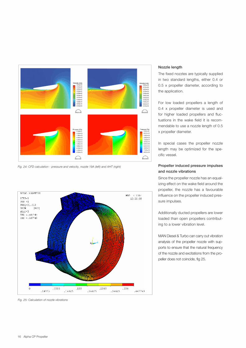
Fig. 25: Calculation of nozzle vibrations
Nozzle length
The.fixed.nozzles.are.typically.supplied.
in. two. standard. lengths,. either. 0.4. or.
0.5. x. propeller. diameter,. according. to.
the.application.
For. low. loaded. propellers. a. length. of.
0.4. x. propeller. diameter. is. used. and.
for. higher. loaded. propellers. and. fluc
tuations. in. the. wake. field. it. is. recom
mendable.to.use.a.nozzle.length.of.0.5.
x.propeller.diameter.
In. special. cases. the. propeller. nozzle.
length.may. be. optimized. for. the. spe
cific.vessel.
Propeller induced pressure impulses
and nozzle vibrations
Since.the.propeller.nozzle.has.an.equal
izing.effect.on.the.wake.field.around.the.
propeller,. the. nozzle. has. a. favourable.
influence.on.the.propeller.induced.pres
sure.impulses.
Additionally.ducted.propellers.are.lower.
loaded.than.open.propellers.contribut
ing.to.a.lower.vibration.level.
MAN.Diesel.&.Turbo.can.carry.out.vibration.
analysis.of. the.propeller.nozzle.with.sup
ports.to.ensure.that.the.natural.frequency.
of.the.nozzle.and.excitations.from.the.pro
peller.does.not.coincide,.fig.25..
6
MARIN (previously Wageningen) andis a simplified version of the 19 typenozzle in order to make it moreproduction-friendly. The 37 typenozzle has, due to its morerounded trailing edge, a betterastern performance though at theexpense of its forward thrust. Re-cently, new nozzle types have ap-peared on the market claiming ahigher performance based on a CFDshape optimisation. At MAN B&WDiesel a new nozzle type calledAlpha High Thrust (AHT) has beendeveloped to increase the perfor-mance compared to earlier types.The AHT nozzle is not a standardiseddesign but customised according toits application. As an example, anAnchor Handling Tug Supply (AHTS)vessel could be optimised for maxi-mum bollard pull, whereas a purseseiner could be optimised for servicespeed. The two nozzle designs willdiffer significantly not only in its ap-pearance, but also in performancewhen compared to a standard off-the-shelf nozzle design. The devel-opment of the AHT nozzle designwill be described in a subsequentpart of this paper.
c. Shaft strut design : A prerequisitefor obtaining a good and uniform in-flow to the propeller is a proper flowalignment of the struts. Up till now,the traditional way of achieving thishas been paint or tuft tests duringmodel experiments. However, theemergence of numerical tools asCFD, including viscous effects, nowmakes it possible to optimise the ori-entation of the struts at an earlierstage.
Other areas of optimisation are therudder shape and the rudder position-ing. Nozzle positioning and tilting arealso very important areas that shouldbe addressed. As many of these itemsare not only related to the propulsionsystem but also adjacent areas like hulland rudder design, it requires that a closecooperation is established between theinvolved parties.
Developing the AHT nozzledesign series
The need for investigating more complexflow phenomena has led MAN B&WDiesel to introduce and implement CFDsoftware. Among those areas which havebenefited from this are nozzle designsand their interaction with the propellers.Viscous effects, that play an importantrole in this respect, are dealt with byusing CFD as it relies on solving the fullNavier-Stokes equations. By systemati-cally designing various nozzle geometriesand subsequently performing CFD cal-culations on each individual parameter,an optimised solution has been estab-lished. Calculations have been performedfor various conditions including bollardpull, astern and ahead.
An iterative process was used in thedevelopment of the AHT nozzle seriesfor an OSV type including the followingsteps:
1. Calculations based on several designproposals were used to determinewhether a bollard pull improvement
compared to the 19A nozzle waspresent. The AHT design was improvedsuccessively finally leading to an opti-mum solution for bollard pull.
An optimum geometry is characterisedby a uniform pressure distribution atthe nozzle inlet followed by an evenconversion of the high velocity flowinto thrust. A comparison betweenthe 19A type nozzle and the AHTdesign shows improvement of boththe relative pressure and the velocitydistribution, see Fig. 4. The pictures onthe left side show the 19A type nozzlewhile the AHT type is to the right.
The higher velocity at the leading edgeof the AHT nozzle design results in alower pressure which generates moreforward thrust. It is also shown thatthe diffusion angle results in a largerpressure at the trailing edge. Thispressure difference contributes to alarger bollard pull. The calculations forthis particular case were performedin model scale. The influence goingfrom model scale to full scale showeda tendency towards a better fullscale performance.
Fig. 4: Pressure and velocity distribution – 19A left and AHT rightFig. 24: CFD calculation pressure and velocity, nozzle 19A (left) and AHT (right)
16 Alpha.CP.Propeller
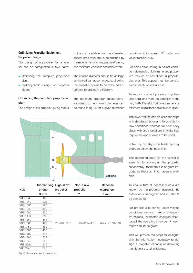
Fig.26: Recommended tip clearance
Optimizing Propeller Equipment Propeller design
The. design. of. a. propeller. for. a. ves
sel. can. be. categorized. in. two. parts:.
.� Optimizing. the. complete. propulsion.
plant
.� Hydrodynamic. design. of. propeller....
blades
Optimizing the complete propulsion
plant
The.design.of.the.propeller,.giving.regard.
Dismantling High skew Non–skew Baseline
Hub of cap propeller propeller clearance
X mm Y Y Z mmVBS...640. 125VBS...740. 225VBS...860. 265VBS...980. 300VBS.1080. 330.VBS.1180. 365VBS.1280. 395.VBS.1380. 420............20–25%.of..D..........25–30%.of.D........Minimum.50–100VBS.1460. 450.VBS.1560. 480.VBS.1680. 515VBS.1800. 555VBS.1940. 590VBS.2080. 635VBS.2240. 680
to.the.main.variables.such.as.diameter,.
speed,.area.ratio.etc,.is.determined.by.
the.requirements.for.maximum.efficiency.
and.minimum.vibrations.and.noise.levels.
The.chosen.diameter.should.be.as.large.
as.the.hull.can.accommodate,.allowing.
the.propeller.speed.to.be.selected.ac
cording.to.optimum.efficiency.
The. optimum. propeller. speed. corre
sponding. to. the. chosen. diameter. can.
be.found.in.fig.18.for.a.given.reference.
condition. (ship. speed. 12. knots. and.
wake.fraction.0.25).
For.ships.often.sailing.in.ballast.condi
tion,.demands.of.fully.immersed.propel
lers.may. cause. limitations. in. propeller.
diameter..This.aspect.must.be.consid
ered.in.each.individual.case.
To. reduce. emitted. pressure. impulses.
and.vibrations.from.the.propeller.to.the.
hull,.MAN.Diesel.&.Turbo.recommend.a.
minimum.tip.clearance.as.shown.in.fig.26.
The.lower.values.can.be.used.for.ships.
with.slender.aft.body.and.favourable.in
flow.conditions.whereas.full.after.body.
ships.with.large.variations.in.wake.field.
require.the.upper.values.to.be.used.
In. twin. screw. ships. the. blade. tip.may.
protrude.below.the.base.line.
The. operating. data. for. the. vessel. is.
essential. for. optimizing. the. propeller.
successfully,.therefore.it.is.of.great.im
portance.that.such.information.is.avail
able.
To. ensure. that. all. necessary. data. are.
known. by. the. propeller. designer,. the.
data.sheets.on.page.25.and.26,.should.
be.completed.
For.propellers.operating.under. varying.
conditions. (service,. max. or. emergen
cy. speeds,. alternator. engaged/disen
gaged).the.operating.time.spent.in.each.
mode.should.be.given.
This.will.provide.the.propeller.designer.
with. the. information. necessary. to. de
sign. a. propeller. capable. of. delivering.
the.highest.overall.efficiency.
17Alpha.CP.Propeller
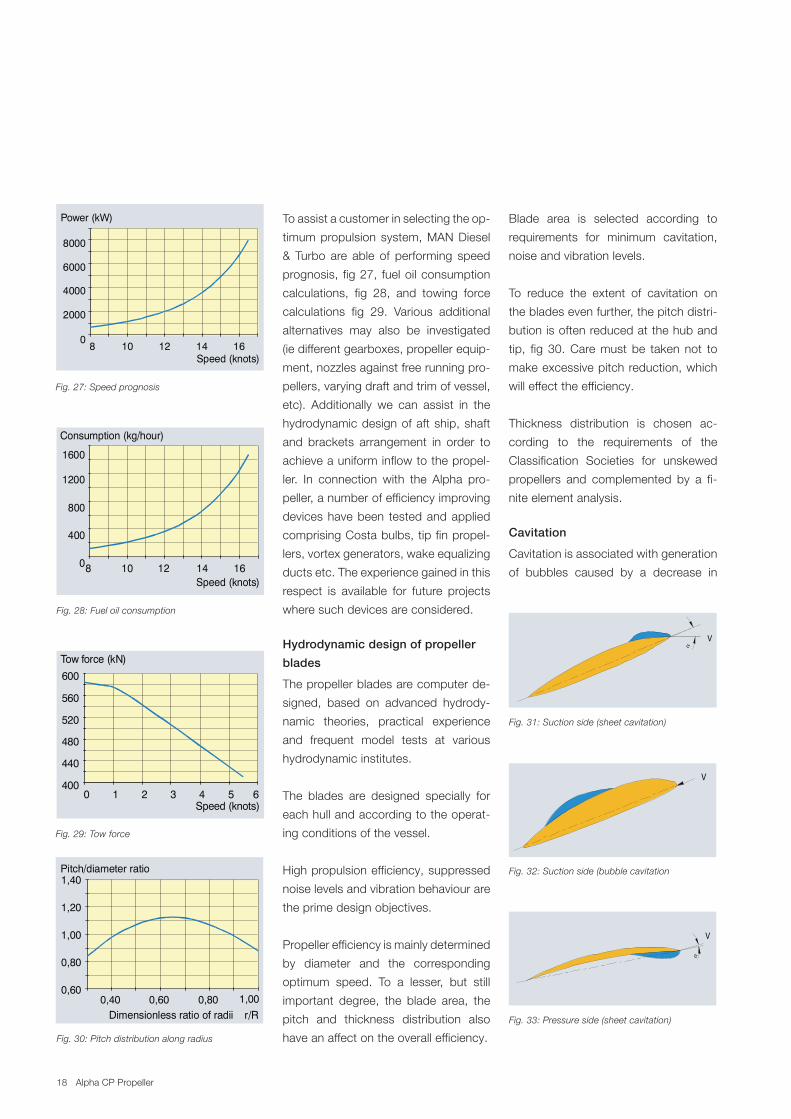
To.assist.a.customer.in.selecting.the.op
timum.propulsion.system,.MAN.Diesel.
&. Turbo. are. able. of. performing. speed.
prognosis,. fig.27,. fuel.oil.consumption.
calculations,. fig. 28,. and. towing. force.
calculations. fig. 29.. Various. additional.
alternatives. may. also. be. investigated.
(ie.different.gearboxes,.propeller.equip
ment,.nozzles.against.free.running.pro
pellers,.varying.draft.and.trim.of.vessel,.
etc).. Additionally. we. can. assist. in. the.
hydrodynamic.design.of.aft.ship,.shaft.
and. brackets. arrangement. in. order. to.
achieve.a.uniform.inflow.to.the.propel
ler.. In. connection. with. the. Alpha. pro
peller,.a.number.of.efficiency.improving.
devices.have.been. tested.and.applied.
comprising.Costa.bulbs,.tip.fin.propel
lers,.vortex.generators,.wake.equalizing.
ducts.etc..The.experience.gained.in.this.
respect. is. available. for. future. projects.
where.such.devices.are.considered...
Hydrodynamic design of propeller
blades
The.propeller.blades.are.computer.de
signed,. based. on. advanced. hydrody
namic. theories,. practical. experience.
and. frequent. model. tests. at. various..
hydrodynamic.institutes.
The. blades. are. designed. specially. for.
each.hull.and.according.to.the.operat
ing.conditions.of.the.vessel.
High.propulsion.efficiency,.suppressed.
noise.levels.and.vibration.behaviour.are.
the.prime.design.objectives.
Propeller.efficiency.is.mainly.determined.
by. diameter. and. the. corresponding..
optimum. speed.. To. a. lesser,. but. still..
important. degree,. the. blade. area,. the.
pitch. and. thickness. distribution. also.
have.an.affect.on.the.overall.efficiency.
Blade. area. is. selected. according. to..
requirements. for. minimum. cavitation,.
noise.and.vibration.levels.
To. reduce. the. extent. of. cavitation. on.
the.blades.even.further,.the.pitch.distri
bution.is.often.reduced.at.the.hub.and.
tip,. fig. 30..Care.must. be. taken. not. to.
make.excessive.pitch.reduction,.which.
will.effect.the.efficiency.
Thickness. distribution. is. chosen. ac
cording. to. the. requirements. of. the.
Classification. Societies. for. unskewed.
propellers. and. complemented. by. a. fi
nite.element.analysis.
Cavitation
Cavitation.is.associated.with.generation.
of. bubbles. caused. by. a. decrease. in..
0
2000
4000
6000
8000
8 10 12 14 16
Power (kW)
Speed (knots)
V
α
Consumption (kg/hour)
0
400
800
1200
1600
8 10 12 14 16Speed (knots)
0 1 2 3 4 5 6400
440
480
520
560
600
Tow force (kN)
Speed (knots)
0,60
0,80
1,00
1,20
1,40Pitch/diameter ratio
0,40 0,60 0,80 1,00Dimensionless ratio of radii r/R
V
V
α
16
0
2000
4000
6000
8000
8 10 12 14 16
Power (kW)
Speed (knots)
Consumption (kg/hour)
0
400
800
1200
1600
8 10 12 14 16Speed (knots)
0 1 2 3 4 5 6400
440
480
520
560
600
Tow force (kN)
Speed (knots)
0,60
0,80
1,00
1,20
1,40Pitch/diameter ratio
0,40 0,60 0,80 1,00
Dimensionless ratio of radii r/R
To assist a customer in selecting the op-timum propulsion system, MAN B&WAlpha are able of performing speedprognosis, fig 20, fuel oil consumptioncalculations, fig 21, and towing forcecalculations fig 22. Various additionalalternatives may also be investigated (iedifferent gearboxes, propeller equipment,nozzles against free running propellers,varying draft and trim of vessel, etc).
Hydrodynamic design ofpropeller blades
The propeller blades are computer de-signed, based on advanced hydrody-namic theories, practical experience andfrequent model tests at varioushydrodynamic institutes.
The blades are designed specially foreach hull and according to the operatingconditions of the vessel.
High propulsion efficiency, suppressednoise levels and vibration behaviour arethe prime design objectives.
Propeller efficiency is mainly determinedby diameter and the correspondingoptimum speed. To a lesser, but stillimportant degree, the blade area, thepitch and thickness distribution alsohave an affect on the overall efficiency.
Blade area is selected according torequirements for minimum cavitation,noise and vibration levels.
To reduce the extent of cavitation onthe blades even further, the pitch distri-bution is often reduced at the hub andtip, fig 23.
Care must be taken not to make exces-sive pitch reduction, which will effect theefficiency.
Thickness distribution is chosen accord-ing to the requirements of the Classifica-tion Societies for unskewed propellers.
Fig. 24: Suction side (sheet cavitation)
Fig. 25: Suction side (bubble cavitation)
V
α
V
V
α
Cavitation
Cavitation is associated with generationof bubbles caused by a decrease inthe local pressure below the prevailingsaturation pressure. The low pressurecan be located at different positions onthe blade as well as in the trailing wake.
When water passes the surface of thepropeller it will experience areas wherethe pressure is below the saturationpressure eventually leading to generationof air bubbles. Further down streamthe bubbles will enter a high pressureregion where the bubbles will collapseand cause noise and vibrations to occur,in particular if the collapse of bubblestakes place on the hull surface.
Three main types of cavitation exist - theirnature and position on the blades canbe characterized as:
Fig. 20: Speed prognosis
Fig. 21: Fuel oil consumption
Fig. 22: Tow force
Fig. 23: Pitch distribution along radius Fig. 26: Pressure side (sheet cavitation)
Fig. 27: Speed prognosis
Fig. 28: Fuel oil consumption
Fig. 29: Tow force
Fig. 30: Pitch distribution along radius
Fig. 31: Suction side (sheet cavitation)
Fig. 32: Suction side (bubble cavitation
Fig. 33: Pressure side (sheet cavitation)
0
2000
4000
6000
8000
8 10 12 14 16
Power (kW)
Speed (knots)
V
α
Consumption (kg/hour)
0
400
800
1200
1600
8 10 12 14 16Speed (knots)
0 1 2 3 4 5 6400
440
480
520
560
600
Tow force (kN)
Speed (knots)
0,60
0,80
1,00
1,20
1,40Pitch/diameter ratio
0,40 0,60 0,80 1,00Dimensionless ratio of radii r/R
V
V
α
0
2000
4000
6000
8000
8 10 12 14 16
Power (kW)
Speed (knots)
Vα
Consumption (kg/hour)
0
400
800
1200
1600
8 10 12 14 16Speed (knots)
0 1 2 3 4 5 6400
440
480
520
560
600
Tow force (kN)
Speed (knots)
0,60
0,80
1,00
1,20
1,40Pitch/diameter ratio
0,40 0,60 0,80 1,00Dimensionless ratio of radii r/R
V
V
α
0
2000
4000
6000
8000
8 10 12 14 16
Power (kW)
Speed (knots)
V
α
Consumption (kg/hour)
0
400
800
1200
1600
8 10 12 14 16Speed (knots)
0 1 2 3 4 5 6400
440
480
520
560
600
Tow force (kN)
Speed (knots)
0,60
0,80
1,00
1,20
1,40Pitch/diameter ratio
0,40 0,60 0,80 1,00Dimensionless ratio of radii r/R
V
V
α
18 Alpha.CP.Propeller
the. local.pressure.below.the.prevailing.
saturation. pressure.. The. low. pressure.
can.be.located.at.different.positions.on.
the.blade.as.well.as.in.the.trailing.wake.
When.water.passes. the.surface.of. the.
propeller.it.will.experience.areas.where.
the. pressure. is. below. the. saturation.
pressure. eventually. leading. to.genera
tion.of.air.bubbles..Further.down.stream.
the. bubbles.will. enter. a. high. pressure.
region.where. the.bubbles.will.collapse.
and.cause.noise.and.vibrations. to.oc
cur,.in.particular.if.the.collapse.of.bub
bles.takes.place.on.the.hull.surface.
Three. main. types. of. cavitation. exist. .
their.nature.and.position.on.the.blades.
can.be.characterized.as:
Sheet cavitation on suction side
The. sheet. cavitation. is. generated. at.
the.leading.edge.due.to.a.low.pressure.
peak.in.this.region..If.the.extent.of.cavi
tation.is.limited.and.the.clearance.to.the.
hull.is.sufficient,.no.severe.noise/vibra
tion. will. occur.. In. case. the. cavitation.
extends.to.more.than.half.of.the.chord.
length,.it.might.develop.into.cloud.cavi
tation..
Cloud.cavitation.often. leads. to.cavita
tion. erosion. of. the. blade. and. should.
therefore. be. avoided.. Sheet. cavitation.
in.the.tip.region.can.develop. into.a.tip.
vortex.which.will.travel.down.stream..If.
the. tip.vortex.extends. to. the. rudder,. it.
may.cause.erosion,.fig..31.
Bubble cavitation
In.case.the.propeller.is.overloaded..ie.
the. blade. area. is. too. small. compared.
to. the. thrust. required. . the.mid. chord.
area.will.be.covered.by.cavitation..This.
type.of. cavitation. is.generally. followed.
by.cloud.cavitation.which.may. lead. to.
0.40 0.800.60 1.00 r/R
r/R
4
2
0
-2
-4
Pressure-2
-4
0
0.4 0.80.6 1.0
Angle of attack (degrees)
2
4Suction
Actual
4
2
0
Spindle torque (kNm)
0 90 180
Single blade
360Angle (degrees)
Allle blades
Skew angle
Centre line shaft
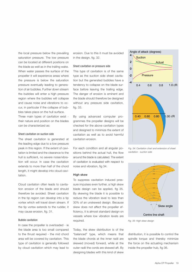
Fig. 34: Cavitation chart and extension of sheet
cavitation suction side
Fig. 35: High skew design
erosion..Due.to.this.it.must.be.avoided.
in.the.design,.fig..32.
Sheet cavitation on pressure side
This. type. of. cavitation. is. of. the. same.
type. as. the. suction. side. sheet. cavita
tion.but.the.generated.bubbles.have.a.
tendency.to.collapse.on.the.blade.sur
face. before. leaving. the. trailing. edge..
The. danger. of. erosion. is. eminent. and.
the.blade.should.therefore.be.designed.
without. any. pressure. side. cavitation,.
fig..33.
By. using. advanced. computer. pro
grammes. the.propeller.designs.will. be.
checked.for.the.above.cavitation.types.
and.designed.to.minimize.the.extent.of.
cavitation. as. well. as. to. avoid. harmful.
cavitation.erosion.
For.each.condition.and.all.angular.po
sitions.behind. the.actual. hull,. the. flow.
around.the.blade.is.calculated..The.extent.
of.cavitation. is.evaluated.with. respect. to.
noise.and.vibration,.fig.34.
High skew
To. suppress. cavitation. induced. pres
sure.impulses.even.further,.a.high.skew.
blade. design. can. be. applied,. fig. 35..
By. skewing. the. blade. it. is. possible. to.
reduce. the. vibration. level. to. less. than.
30%.of.an.unskewed.design..Because.
skew.does. not. affect. the. propeller. ef
ficiency,.it.is.almost.standard.design.on.
vessels. where. low. vibration. levels. are.
required.
Today,. the. skew. distribution. is. of. the.
“balanced”. type,. which. means. that.
the.blade.chords.at. the. inner. radii. are.
skewed. (moved). forward,. while. at. the.
outer.radii.the.cords.are.skewed.aft..By.
designing.blades.with.this.kind.of.skew.
distribution,.it.is.possible.to.control.the.
spindle. torque. and. thereby. minimize.
the. force.on. the.actuating.mechanism.
inside.the.propeller.hub,.fig.36.
0.40 0.800.60 1.00 r/R
r/R
4
2
0
-2
-4
Pressure-2
-4
0
0.4 0.80.6 1.0
Angle of attack (degrees)
2
4Suction
Actual
4
2
0
Spindle torque (kNm)
0 90 180
Single blade
360Angle (degrees)
Allle blades
Skew angle
Centre line shaft
19Alpha.CP.Propeller
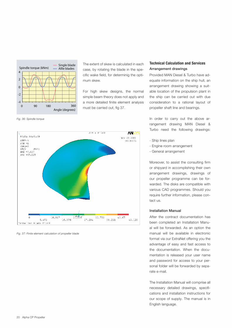
Fig. 37: Finite element calculation of propeller blade
The.extent.of.skew.is.calculated.in.each.
case,.by.rotating.the.blade.in.the.spe
cific.wake.field,.for.determinig.the.opti
mum.skew...
For. high. skew. designs,. the. normal.
simple.beam.theory.does.not.apply.and.
a.more.detailed. finite.element.analysis.
must.be.carried.out,.fig.37.
Technical Calculation and ServicesArrangement drawings
Provided.MAN.Diesel.&.Turbo.have.ad
equate.information.on.the.ship.hull,.an.
arrangement. drawing. showing. a. suit
able. location.of.the.propulsion.plant. in.
the. ship. can. be. carried. out. with. due.
consideration. to. a. rational. layout. of.
propeller.shaft.line.and.bearings.
In. order. to. carry. out. the. above. ar
rangement. drawing. MAN. Diesel. &.
Turbo. need. the. following. drawings:.
.Ship.lines.plan
.Engine.room.arrangement
.General.arrangement
Moreover,. to.assist. the.consulting. firm.
or.shipyard.in.accomplishing.their.own.
arrangement. drawings,. drawings. of.
our. propeller. programme. can. be. for
warded..The.disks.are.compatible.with.
various.CAD.programmes..Should.you.
require.further.information,.please.con
tact.us.
Installation Manual
After. the. contract. documentation. has.
been. completed. an. Installation.Manu
al.will. be. forwarded..As. an. option. the.
manual. will. be. available. in. electronic.
format.via.our.ExtraNet.offering.you.the.
advantage. of. easy. and. fast. access. to.
the. documentation.. When. the. docu
mentation. is. released. your. user. name.
and.password. for. access. to. your.per
sonal.folder.will.be.forwarded.by.sepa
rate.email..
The.Installation.Manual.will.comprise.all.
necessary. detailed. drawings,. specifi
cations.and. installation. instructions. for.
our.scope.of. supply..The.manual. is. in.
English.language.
Fig. 36: Spindle torque
0.40 0.800.60 1.00 r/R
r/R
4
2
0
-2
-4
Pressure-2
-4
0
0.4 0.80.6 1.0
Angle of attack (degrees)
2
4Suction
Actual
4
2
0
Spindle torque (kNm)
0 90 180
Single blade
360Angle (degrees)
Allle blades
Skew angle
Centre line shaft
20 Alpha.CP.Propeller
21
Torsional stress amplitude (N/mm )2
150
100
50
040 50 60 70 80 90 100 110 120 130 Engine speed r/min
Rule limit fortransient running
Rule limit forcontinuous running
Actual stresses Barred speed range
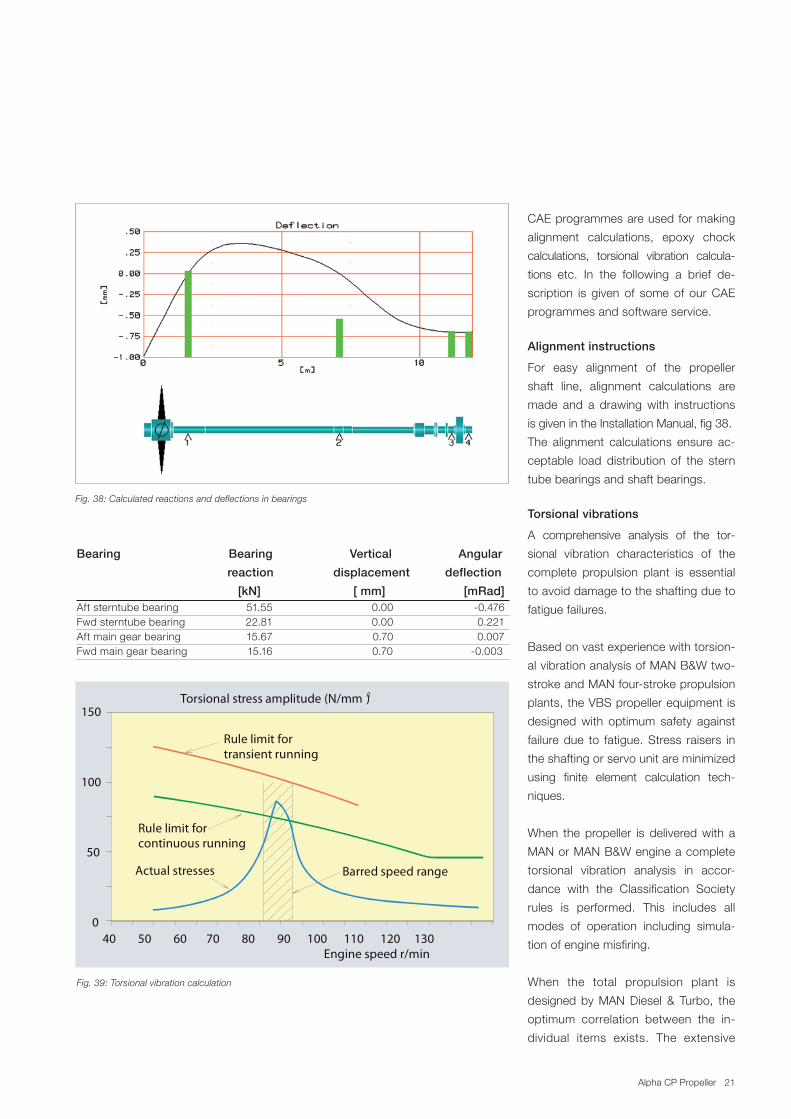
Fig. 38: Calculated reactions and deflections in bearings
Bearing Bearing Vertical Angular
reaction displacement deflection
[kN] [ mm] [mRad]Aft.sterntube.bearing.. . ..51.55. . .....0.00. . ....0.476Fwd.sterntube.bearing. . ..22.81. . .....0.00. . .....0.221Aft.main.gear.bearing. . ..15.67. . .....0.70. . .....0.007Fwd.main.gear.bearing. ...........15.16................................0.70.........................0.003
Fig. 39: Torsional vibration calculation
CAE.programmes.are.used.for.making.
alignment. calculations,. epoxy. chock.
calculations,. torsional. vibration. calcula
tions. etc.. In. the. following. a. brief. de
scription. is. given. of. some.of. our.CAE.
programmes.and.software.service.
Alignment instructions
For. easy. alignment. of. the. propeller.
shaft. line,. alignment. calculations. are.
made. and. a. drawing.with. instructions.
is.given.in.the.Installation.Manual,.fig.38.
The. alignment. calculations. ensure. ac
ceptable. load. distribution. of. the. stern.
tube.bearings.and.shaft.bearings.
Torsional vibrations
A. comprehensive. analysis. of. the. tor
sional. vibration. characteristics. of. the.
complete. propulsion. plant. is. essential.
to.avoid.damage.to.the.shafting.due.to.
fatigue.failures.
Based.on.vast.experience.with.torsion
al.vibration.analysis.of.MAN.B&W.two
stroke.and.MAN.fourstroke.propulsion.
plants,.the.VBS.propeller.equipment.is.
designed.with. optimum. safety. against.
failure.due. to. fatigue..Stress. raisers. in.
the.shafting.or.servo.unit.are.minimized.
using. finite. element. calculation. tech
niques.
When. the.propeller. is. delivered.with. a.
MAN.or.MAN.B&W.engine.a.complete.
torsional. vibration. analysis. in. accor
dance. with. the. Classification. Society.
rules. is. performed.. This. includes. all.
modes. of. operation. including. simula
tion.of.engine.misfiring.
When. the. total. propulsion. plant. is.
designed.by.MAN.Diesel. &. Turbo,. the.
optimum. correlation. between. the. in
dividual. items. exists.. The. extensive.
21
Torsional stress amplitude (N/mm )2
150
100
50
040 50 60 70 80 90 100 110 120 130 Engine speed r/min
Rule limit fortransient running
Rule limit forcontinuous running
Actual stresses Barred speed range
21Alpha.CP.Propeller
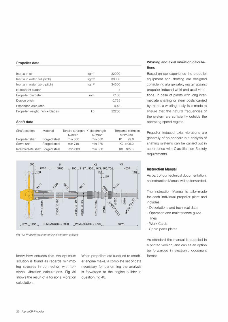
Fig. 40: Propeller data for torsional vibration analysis
Propeller data
.
Inertia.in.air.. kgm².. 32900.
Inertia.in.water.(full.pitch).. kgm².. 39300.
Inertia.in.water.(zero.pitch).. kgm².. 34500.
Number.of.blades.. . 4.
Propeller.diameter.. mm.. 6100.
Design.pitch.. . 0.755.
Expanded.area.ratio.. .. 0.48.
Propeller.weight.(hub.+.blades).. kg.. 22230.
Shaft data
Shaft.section.. Material. .Tensile.strength. Yield.strength. Torsional.stiffness................................. ......N/mm². .......N/mm²....................MNm/rad.Propeller.shaft.. Forged.steel.. . . min.600. . ..min.350...................K1.. .99.0
Servo.unit.. Forged.steel. . ..min.740. . ..min.375.............. .....K2.1105.0
Intermediate.shaft.. Forged.steel. ......min.600. . . ...min.350..................K3...105.6
Whirling and axial vibration calcula
tions
Based.on.our.experience.the.propeller.
equipment. and. shafting. are. designed.
considering.a.large.safety.margin.against.
propeller.induced.whirl.and.axial.vibra
tions.. In.case.of.plants.with. long.inter
mediate. shafting. or. stern. posts. carried.
by.struts,.a.whirling.analysis.is.made.to.
ensure. that. the. natural. frequencies. of.
the. system. are. sufficiently. outside. the.
operating.speed.regime.
Propeller. induced. axial. vibrations. are.
generally.of.no.concern.but.analysis.of.
shafting.systems.can.be.carried.out. in.
accordance.with.Classification.Society.
requirements.
Instruction Manual
As.part.of.our.technical.documentation,.
an.Instruction.Manual.will.be.forwarded.
The. Instruction. Manual. is. tailormade.
for. each. individual. propeller. plant. and.
includes:
.Descriptions.and.technical.data
.Operation.and.maintenance.guide.....
...lines
.Work.Cards
.Spare.parts.plates
As. standard. the.manual. is. supplied. in.
a.printed.version,.and.can.as.an.option.
be. forwarded. in. electronic. document.
format.knowhow.ensures. that. the.optimum.
solution. is. found.as. regards.minimiz
ing. stresses. in. connection. with. tor
sional. vibration. calculations.. Fig. 39.
shows.the.result.of.a.torsional.vibration.
calculation..
When.propellers.are.supplied.to.anoth
er.engine.make,.a.complete.set.of.data.
necessary. for. performing. the. analysis.
is. forwarded. to. the. engine. builder. in.
question,.fig.40.
22
SPEC.FILLET
R200 R200
SPEC
. FIL
LET
K34037754
11046511003785 943950
K21197
110110
R100
R200
2000K1
R200 R200
∅∅
570
/ 18
0
600
150
5476W-MEASURE = 3700S-MEASURE = 598011551175
∅∅
560
/ 18
0
∅∅
565
/ 18
0
∅∅
555
/ 18
0
∅∅
740
/ 56
0
∅51
0
∅52
0
∅51
0
22 Alpha.CP.Propeller
21
HUB Max shaftHUB Max shaftHUB Max shaftHUB Max shaftHUB Max shaft ODS/ODS/ODS/ODS/ODS/ A A A A A * B* B* B* B* B LLLLL * M * W-min * W-min* M * W-min * W-min* M * W-min * W-min* M * W-min * W-min* M * W-min * W-min FFFFFVBS- DiameterVBS- DiameterVBS- DiameterVBS- DiameterVBS- Diameter ODGODGODGODGODG ODSODSODSODSODS ODGODGODGODGODG ODFODFODFODFODFTTTTTypeypeypeypeype [mm][mm][mm][mm][mm] TTTTTypeypeypeypeype [mm] [mm] [mm] [mm] [mm] [mm][mm][mm][mm][mm] [mm][mm][mm][mm][mm] [mm][mm][mm][mm][mm] [mm][mm][mm][mm][mm] [mm][mm][mm][mm][mm] [mm][mm][mm][mm][mm]
640 270 180 500 330 491 604 1316 780 640 270 200 500 355 491 604 1316 780 640 270 225 500 380 491 604 2096 1331 780 740 307 200 580 355 569 661 1316 780 740 307 225 580 385 569 661 2096 1331 780 740 307 250 580 415 569 661 2231 1401 780 740 307 280 580 420 569 681 2352 1522 780 860 364 225 670 385 653 722 2096 1331 780 860 364 250 670 415 653 722 2231 1401 780 860 364 280 670 455 653 742 2352 1522 780 860 364 310 670 475 653 747 2367 1557 780 860 364 330 670 475 653 747 2482 1629 780 980 416 250 760 435 746 794 2231 1401 780 980 416 280 760 475 746 814 2352 1522 780 980 416 310 760 510 746 819 2367 1557 780 980 416 330 760 535 746 844 2482 1629 780 980 416 350 760 550 746 844 2503 1650 780 980 416 375 760 550 746 844 2578 1698 7801080 458 280 840 475 821 890 2352 1522 8201080 458 310 840 510 821 895 2367 1557 8201080 458 330 840 535 821 920 2482 1629 8201080 458 350 840 560 821 920 2503 1650 8201080 458 375 840 590 821 920 2578 1698 8201080 458 400 840 590 821 920 2518 1738 8201180 502 310 915 530 885 947 2367 1557 8201180 502 330 915 555 885 972 2482 1629 8201180 502 350 915 580 885 972 2503 1650 8201180 502 375 915 610 885 972 2578 1698 8201180 502 400 915 640 885 972 2518 1738 8201180 502 425 915 655 885 972 2648 1778 8201180 502 450 915 655 885 972 2691 1831 8201280 560 350 1000 580 957 1025 2503 1650 9101280 560 375 1000 610 957 1025 2578 1698 9101280 560 400 1000 640 957 1025 2518 1738 9101280 560 425 1000 670 957 1050 2648 1778 9101280 560 450 1000 700 957 1050 2691 1831 9101280 560 475 1000 710 957 1050 2701 1881 9101380 578 375 1070 610 1030 1081 2578 1698 9101380 578 400 1070 640 1030 1081 2518 1738 9101380 578 425 1070 670 1030 1096 2648 1778 9101380 578 450 1070 700 1030 1096 2691 1831 9101380 578 475 1070 730 1030 1101 2701 1881 9101380 578 510 1070 730 1030 1101 2923 1913 9101460 612 400 1130 650 1100 1121 2518 1738 9101460 612 425 1130 680 1100 1136 2648 1778 9101460 612 450 1130 710 1100 1136 2691 1831 9101460 612 475 1130 740 1100 1141 2701 1881 9101460 612 510 1130 775 1100 1141 2923 1913 9101460 612 560 1130 775 1100 1141 3001 1966 9101560 650 425 1210 680 1175 1197 2648 1778 10001560 650 450 1210 710 1175 1197 2691 1831 10001560 650 475 1210 740 1175 1202 2701 1881 10001560 650 510 1210 785 1175 1202 2923 1913 10001560 650 560 1210 810 1175 1237 3001 1966 10001560 650 600 1210 810 1175 1237 3101 2051 10001680 727 450 1295 720 1278 1274 2691 1831 10001680 727 475 1295 750 1278 1279 2701 1881 10001680 727 510 1295 795 1278 1279 2923 1913 10001680 727 560 1295 855 1278 1314 3001 1966 10001680 727 600 1295 900 1278 1344 3101 2051 10001800 764 510 1390 795 1367 1332 2923 1913 11201800 764 560 1390 855 1367 1367 3001 1966 11201800 764 600 1390 905 1367 1397 3101 2051 11201940 826 510 1500 805 1458 1412 2923 1913 11201940 826 560 1500 865 1458 1447 3001 1966 11201940 826 600 1500 915 1458 1477 3101 2051 1120
* Guiding approx dimensions* Guiding approx dimensions* Guiding approx dimensions* Guiding approx dimensions* Guiding approx dimensions
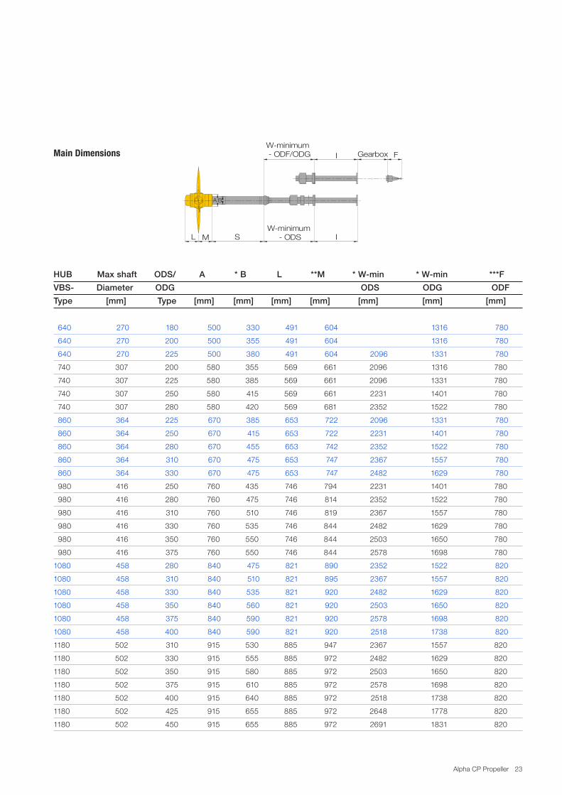
MainDimensions
A B
Gearbox F
L M S IW�minimum
� ODS
W�minimum � ODF/ODG I
..640. 270. 180. ..500. 330. ..491. ..604. . . 1316. .780
..640. 270. 200. ..500. 355. ..491. ..604. . . 1316. ..780
..640. 270. 225. ..500. 380. ..491. ..604. .2096. 1331. ..780
..740. 307. 200. ..580. 355. ..569. ..661. . 2096. 1316. ..780
..740. 307. 225. ..580. 385. ..569. ..661. . 2096. 1331. ..780
..740. 307. 250. ..580. 415. ..569. ..661. . 2231. 1401. ..780
..740. 307. 280. ..580. 420. ..569. ..681. . 2352. 1522. ..780
..860. 364. 225. ..670. 385. ..653. ..722. .2096. 1331. ..780
..860. 364. 250. ..670. 415. ..653. ..722. .2231. 1401. ..780
..860. 364. 280. ..670. 455. ..653. ..742. .2352. 1522. ..780
..860. 364. 310. ..670. 475. ..653. ..747. .2367. 1557. ..780
..860. 364. 330. ..670. 475. ..653. ..747. .2482. 1629. ..780
..980. 416. 250. ..760. 435. ..746. ..794. . 2231. 1401. ..780
..980. 416. 280. ..760. 475. ..746. ..814. . 2352. 1522. ..780
..980. 416. 310. ..760. 510. ..746. ..819. . 2367. 1557. ..780
..980. 416. 330. ..760. 535. ..746. ..844. . 2482. 1629. ..780
..980. 416. 350. ..760. 550. ..746. ..844. . 2503. 1650. ..780
..980. 416. 375. ..760. 550. ..746. ..844. . 2578. 1698. ..780
1080. 458. 280. ..840. 475. ..821. ..890. .2352. 1522. ..820
1080. 458. 310. ..840. 510. ..821. ..895. .2367. 1557. ..820
1080. 458. 330. ..840. 535. ..821. ..920. .2482. 1629. ..820
1080. 458. 350. ..840. 560. ..821. ..920. .2503. 1650. ..820
1080. 458. 375. ..840. 590. ..821. ..920. .2578. 1698. ..820
1080. 458. 400. ..840. 590. ..821. ..920. .2518. 1738. ..820
1180. 502. 310. ..915. 530. ..885. ..947. . 2367. 1557. ..820
1180. 502. 330. ..915. 555. ..885. ..972. . 2482. 1629. ..820
1180. 502. 350. ..915. 580. ..885. ..972. . 2503. 1650. ..820
1180. 502. 375. ..915. 610. ..885. ..972. . 2578. 1698. ..820
1180. 502. 400. ..915. 640. ..885. ..972. . 2518. 1738. ..820
1180. 502. 425. ..915. 655. ..885. ..972. . 2648. 1778. ..820
1180. 502. 450. ..915. 655. ..885. ..972. . 2691. 1831. ..820
HUB Max shaft ODS/ A * B L **M * Wmin * Wmin ***F
VBS Diameter ODG ODS ODG ODF
Type [mm] Type [mm] [mm] [mm] [mm] [mm] [mm] [mm]
Main Dimensions
23Alpha.CP.Propeller
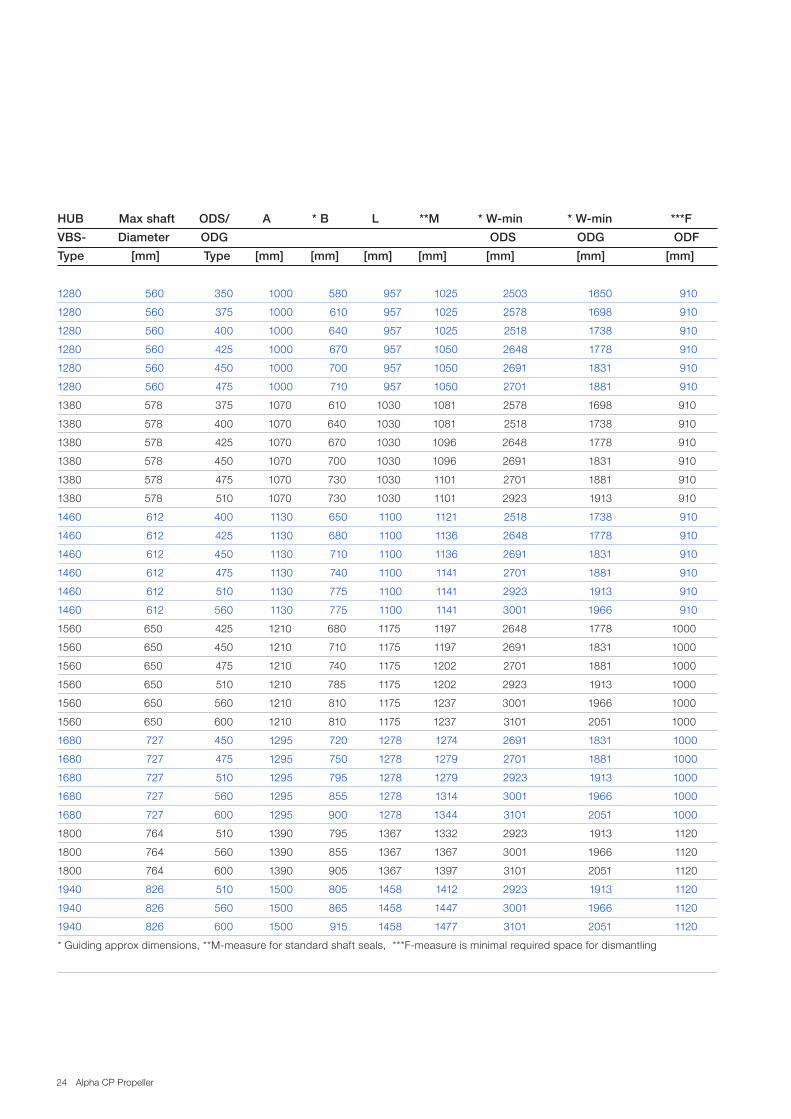
1280. 560. 350. 1000. 580. ..957. 1025. .2503. 1650. ..910
1280. 560. 375. 1000. 610. ..957. 1025. .2578. 1698. ..910
1280. 560. 400. 1000. 640. ..957. 1025. .2518. 1738. ..910
1280. 560. 425. 1000. 670. ..957. 1050. .2648. 1778. ..910
1280. 560. 450. 1000. 700. ..957. 1050. .2691. 1831. ..910
1280. 560. 475. 1000. 710. ..957. 1050. .2701. 1881. ..910
1380. 578. 375. 1070. 610. 1030. 1081. . 2578. 1698. ..910
1380. 578. 400. 1070. 640. 1030. 1081. . 2518. 1738. ..910
1380. 578. 425. 1070. 670. 1030. 1096. . 2648. 1778. ..910
1380. 578. 450. 1070. 700. 1030. 1096. . 2691. 1831. ..910
1380. 578. 475. 1070. 730. 1030. 1101. . 2701. 1881. ..910
1380. 578. 510. 1070. 730. 1030. 1101. . 2923. 1913. ..910
1460. 612. 400. 1130. 650. 1100. 1121. .2518. 1738. ..910
1460. 612. 425. 1130. 680. 1100. 1136. .2648. 1778. ..910
1460. 612. 450. 1130. 710. 1100. 1136. .2691. 1831. ..910
1460. 612. 475. 1130. 740. 1100. 1141. .2701. 1881. ..910
1460. 612. 510. 1130. 775. 1100. 1141. .2923. 1913. ..910
1460. 612. 560. 1130. 775. 1100. 1141. .3001. 1966. ..910
1560. 650. 425. 1210. 680. 1175. 1197. . 2648. 1778. 1000
1560. 650. 450. 1210. 710. 1175. 1197. . 2691. 1831. 1000
1560. 650. 475. 1210. 740. 1175. 1202. . 2701. 1881. 1000
1560. 650. 510. 1210. 785. 1175. 1202. . 2923. 1913. 1000
1560. 650. 560. 1210. 810. 1175. 1237. . 3001. 1966. 1000
1560. 650. 600. 1210. 810. 1175. 1237. . 3101. 2051. 1000
1680. 727. 450. 1295. 720. 1278. 1274. .2691. 1831. 1000
1680. 727. 475. 1295. 750. 1278. 1279. .2701. 1881. 1000
1680. 727. 510. 1295. 795. 1278. 1279. .2923. 1913. 1000
1680. 727. 560. 1295. 855. 1278. 1314. .3001. 1966. 1000
1680. 727. 600. 1295. 900. 1278. 1344. .3101. 2051. 1000
1800. 764. 510. 1390. 795. 1367. 1332. .2923. 1913. 1120
1800. 764. 560. 1390. 855. 1367. 1367. .3001. 1966. 1120
1800. 764. 600. 1390. 905. 1367. 1397. .3101. 2051. 1120
1940. 826. 510. 1500. 805. 1458. 1412. .2923. 1913. 1120
1940. 826. 560. 1500. 865. 1458. 1447. .3001. 1966. 1120
1940. 826. 600. 1500. 915. 1458. 1477. .3101. 2051. 1120
*.Guiding.approx.dimensions,.**Mmeasure.for.standard.shaft.seals,..***Fmeasure.is.minimal.required.space.for.dismantling. .
. . . . .
HUB Max shaft ODS/ A * B L **M * Wmin * Wmin ***F
VBS Diameter ODG ODS ODG ODF
Type [mm] Type [mm] [mm] [mm] [mm] [mm] [mm] [mm]
24 Alpha.CP.Propeller
For.propeller.layout.please.provide.the.following.information:
1.. S.:.________.mm.. W.:.________.mm.. I.:.________.mm. (as.shown.above)
2.. Stern.tube.and.shafting.arrangement.layout
3.. Stern.tube.mountings:...Expoxy.mounted..or.interference.fitted.
4.. Propeller.aperture.drawing
5.. Copies.of.complete.set.of.reports.from.model.tank.test.(resistance.test,.selfpropulsion.test.and.... .
. wake.measurement)..In.case.model.test.is.not.available.section.10.must.be.filled.in.
6.. Drawing.of.lines.plan
7.. Classification.society. :._____________..Notation:___________Ice.class.notation.:______________
8.. Maximum.rated.power.of.shaft.generator.:.__________.kW
9.. To.obtain.the.highest.propeller.efficiency.please.identify.the.most.common.service.condition.for.the.vessel:
. Ship.speed.. . :.__________.kn. . Engine.service.load. . :.__________.%
. Service/sea.margin.. :.__________.%. . Shaft.gen..service.load. . :.__________.kW
. Draft. . . :.__________.m
......
Project.:.._________________________................................Type.of.vessel.:.._______________________
22
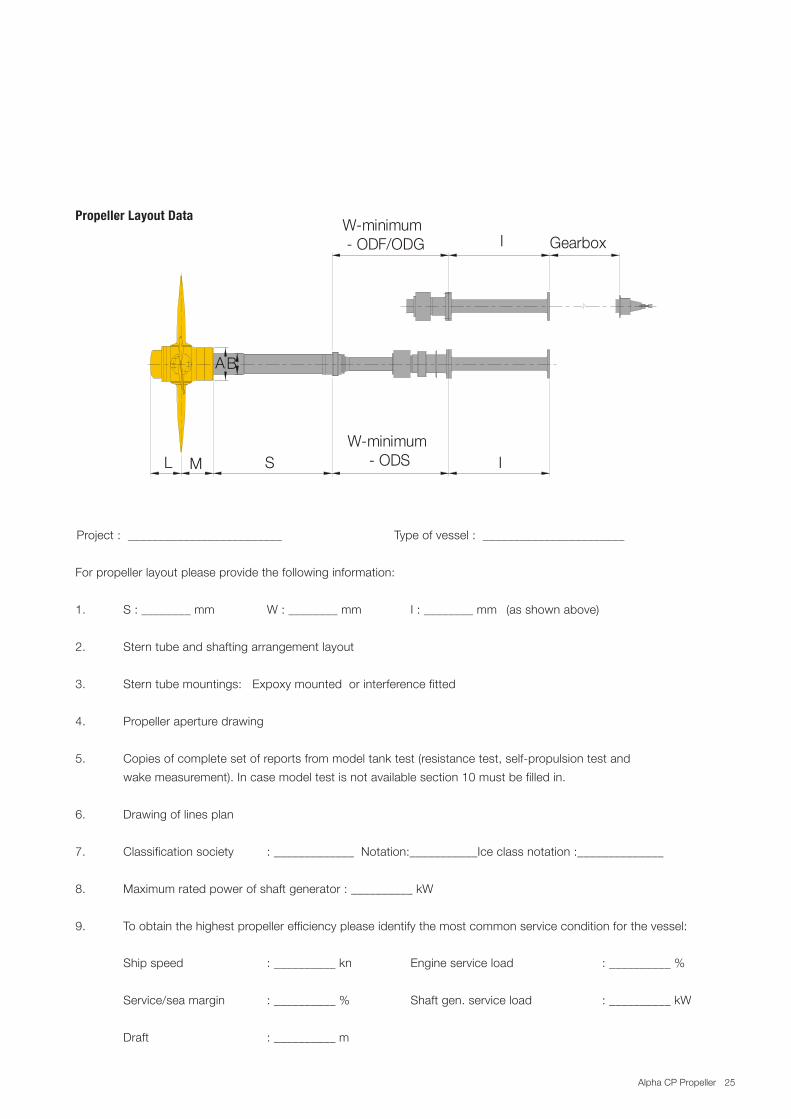
Propeller Layout Data
For propeller layout please provide the following information:
1. S : ________ mm W : ________ mm I : ________ mm (as shown above)
2. Stern tube and shafting arrangement layout
3. Stern tube mountings: Expoxy mounted or interference fitted
4. Propeller aperture drawing
5. Copies of complete set of reports from model tank test (resistance test, self-propulsion test andwake measurement). In case model test is not available section 10 must be filled in.
6. Drawing of lines plan
7. Classification society : _____________ Notation:___________Ice class notation :______________
8. Maximum rated power of shaft generator : __________ kW
9. To obtain the highest propeller efficiency please identify the most commonservice condition for the vessel:
Ship speed : __________ kn Engine service load : __________ %
Service/sea margin : __________ % Shaft gen. service load : __________ kW
Draft : __________ m
AB
Gearbox
L M S IW�minimum
� ODS
W�minimum � ODF/ODG I
Project : _________________________ Type of vessel : _______________________
Propeller Layout Data
25Alpha.CP.Propeller
10.. Vessel.Main.Dimensions...(Please.fillin.if.model.test.is.not.available)
Nom Dim Ballast Loaded
Lengthbetweenperpendiculars LPP m
Lengthofloadwaterline LWL m
Breadth B m
Draftatforwardperpendicular TF m
Draftataftperpendicular TA m
Displacement Ñ m3
Blockcoefficient(LPP) CB
Midshipcoefficient CM
Waterplaneareacoefficient CWL
Wettedsurfacewithappendages S m2
CentreofbuoyancyforwardofLPP/2 LCB m
Propellercentreheightabovebaseline H m
Bulbsectionareaatforwardperpendicular AB m2
11. Comments:_______________________________________________________
_________________________________________________________________
_________________________________________________________________
_________________________________________________________________
Date:_________________________Signature:___________________________
26 Alpha.CP.Propeller

27Alpha.CP.Propeller

MAN Diesel & Turbo
Niels.Juels.Vej.151
DK9900.Frederikhavn,.Denmark
Phone.+45.96.20.41.00
Fax. +45.96.20.40.30
www.mandieselturbo.com
All.data.provided.in.this.docum
ent.is.nonbinding..This.data.serves.informational.purposes.only.and.is.especially.not.guaranteed.in.any.w
ay..
Depending.on.the.subsequent.specific.individual.projects,.the.relevant.data.m
ay.be.subject.to.changes.and.will.be.assessed.and.determ
ined.
individually.for.each.project..This.will.depend.on.the.particular.characteristics.of.each.individual.project,.especially.specific.site.and.operational.
conditions.·.Copyright.©
.MAN.Diesel.&
.Turbo.·.Subject.to.m
odification.in.the.interest.of.technical.progress..5510010100ppr.Nov.2010.P
rinted.
in.Denm
ark


![Launchpad Mini [MK3]](https://img.pdfslide.net/doc/110x75/61bd4f1261276e740b117f87/launchpad-mini-mk3.jpg)
