Embed Size (px)
Citation preview
USERMANUAL5/8-PortGigabitEthernetSmart-Lite/PoESwitches
GS-7608,8-PortPoEGigabitEthernetSmart-LiteSwitch
GS-7605,5-PortPoEGigabitEthernetSmart-LiteSwitch
GS-7408,8-PortGigabitEthernetSmart-LiteSwitch
GS-7405,5-PortGigabitEthernetSmart-LiteSwitch
Version V1.00.45, July, 2017
Table of Contents i
TableofContents
1. Introduction.............................................................................................................21.1. Overview......................................................................................................................21.2. Packagecontents.........................................................................................................21.3. Features.......................................................................................................................21.4. ProductComponents...................................................................................................31.4.1. SwitchViews..................................................................................................................31.4.2. LEDIndicators.........................................................................................................5
2. Installation...............................................................................................................82.1. PlacementTips..................................................................................................................82.2. DesktopInstallation.....................................................................................................82.3. RackmountInstallation................................................................................................9
3. GettingStarted........................................................................................................113.1. Power..........................................................................................................................113.1.1. InstallingPower.....................................................................................................113.1.2. ConnectingtotheNetwork..................................................................................123.1.3. PoweroverEthernet(PoE)Considerations..........................................................123.2. StartingtheWeb-basedConfigurationUtility............................................................143.2.1. BrowserRestrictions.............................................................................................143.2.2. LaunchingtheConfigurationUtility......................................................................143.2.3. LoggingIn..............................................................................................................153.2.4. LoggingOut...........................................................................................................15
4. Web-basedSwitchConfiguration............................................................................16
4.1. System.......................................................................................................................174.1.1. Management........................................................................................................184.1.2. Port.......................................................................................................................194.1.3. VLAN.....................................................................................................................204.1.4. Trunking................................................................................................................224.1.5. Mirror....................................................................................................................234.1.6. QoS.......................................................................................................................244.1.7. BroadcastStormControl......................................................................................26
Table of Contents ii
4.1.8. RateLimiting.........................................................................................................274.1.9. LoopDetect/Prevent............................................................................................294.1.10. IGMPSnooping.....................................................................................................304.2. PoE.............................................................................................................................314.2.1. Password...............................................................................................................334.2.2. Logout...................................................................................................................33
5. FederalCommunicationCommissionInterferenceStatement.................................34
1
SafetyandRegulatory
AudienceThisguideisforthenetworkingprofessionalmanagingthestandaloneGS-7000switchseries.ItisrecommendedthatonlyprofessionalswithexperienceworkingwithComtrendnetworkingdevicesandwhoarefamiliarwiththeEthernetandlocalareanetworkingterminology,shouldservicetheequipment.ConventionsThefollowingconventionsareusedinthismanualtoconveyinstructionsandinformation:
Commanddescriptionsusetheseconventions:
• Commandsandkeywordsareinboldfacetext.
• Argumentsforwhichyousupplyvaluesareinitalic.
• Squarebrackets([])meanoptionalelements.
• Braces({})grouprequiredchoices,andverticalbars(|)separatethealternativeelements.
• Bracesandverticalbarswithinsquarebrackets([{|}])meanarequiredchoicewithinanoptionalelement.
Interactiveexamplesusetheseconventions:
• Nonprintingcharacters,suchaspasswordsortabs,areinanglebrackets(<>).Notesandcautions
usethefollowingconventionsandsymbols:
NoteMeansadditionalinformation.Notescontainadditionalusefulinformationorreferencestomaterialavailableoutsideofthisdocument.
CautionIndicatesthatthereadermustbecareful.InasituationwhereaCautionislisted,ausermaycauseequipmentdamageorlossofdata.
Introduction 2
1. IntroductionThankyouforpurchasingaComtrendGigabitEthernetSmart-Liteswitchdevice.TheSeriesincludesbothPoEandnon-PoEmodelspoweredbyComtrend’sWebSmartPoEandWebSmartinterface,respectively.
ThisdocumentisintendedtoprovidehardwareinstallationinstructionsaswellasanoverviewoftheinterfaceandmanagementfunctionsoftheWebSmartweb-basedsoftware.1.1. OverviewTheComtrendGigabitEthernetSmart-LiteSwitchDesktopSeriesincludesthefollowingmodels:GS-7608,GS-7605,GS-7408,andGS-7405.TheGS-7600andGS-7400modelsarefanlesssmart-liteswitchessupporting5to8GigabitEthernetports.TheGigaEthernetPoESwitchprovidesaseamlessnetworkconnectionwithintegrated1000MbpsGigabitEthernet,100MbpsFastEthernetand10MbpsEthernetnetworkcapabilities.2.2. PackagecontentsBeforeusingtheproduct,checkthattheitemslistedbelowareincludedandingoodcondition.Ifanyitemdoesnotaccordwiththetable,pleasecontactyourdealerimmediately.
• Oneofthefollowing:ComtrendGS-7608,GS-7605,GS-7408,orGS-7405
• ACtoDCExternalPSUwithPowerCord(GS-7605only)
• ACPowerCordorExternalPowerAdapter(checkyourmodeltoconfirm)
• PowerCord
• RackMountKit(GS-7608only)
• QuickInstallationGuide
• ManualCD
• FootPads3.3. Features
• Supportsupto810/100/1000MbpsGigabitEthernetports
• IEEE802.3af/atPoEcomplianttosimplifydeploymentandinstallation
• SupportsPoEupto30Wperportwith130W(GS-7608only),65W(GS-7605only),totalpowerbudget
• Automaticallydetectspowereddevices(PD)andpowerconsumptionlevels
• IEEE802.1QVLANallowsnetworksegmentationtoenhanceperformanceandsecurity
• IEEE802.1pQoSwith4priorityqueues
Introduction 3
• Supportsaccesscontrollist(ACL)
• Switchcapacity:GS-7608&GS-7408:16Gbps;GS-7605&GS-7405:10Gbps,forwardingrate:11.9Mbps
• SupportsIGMPSnoopingv1/v2/v3
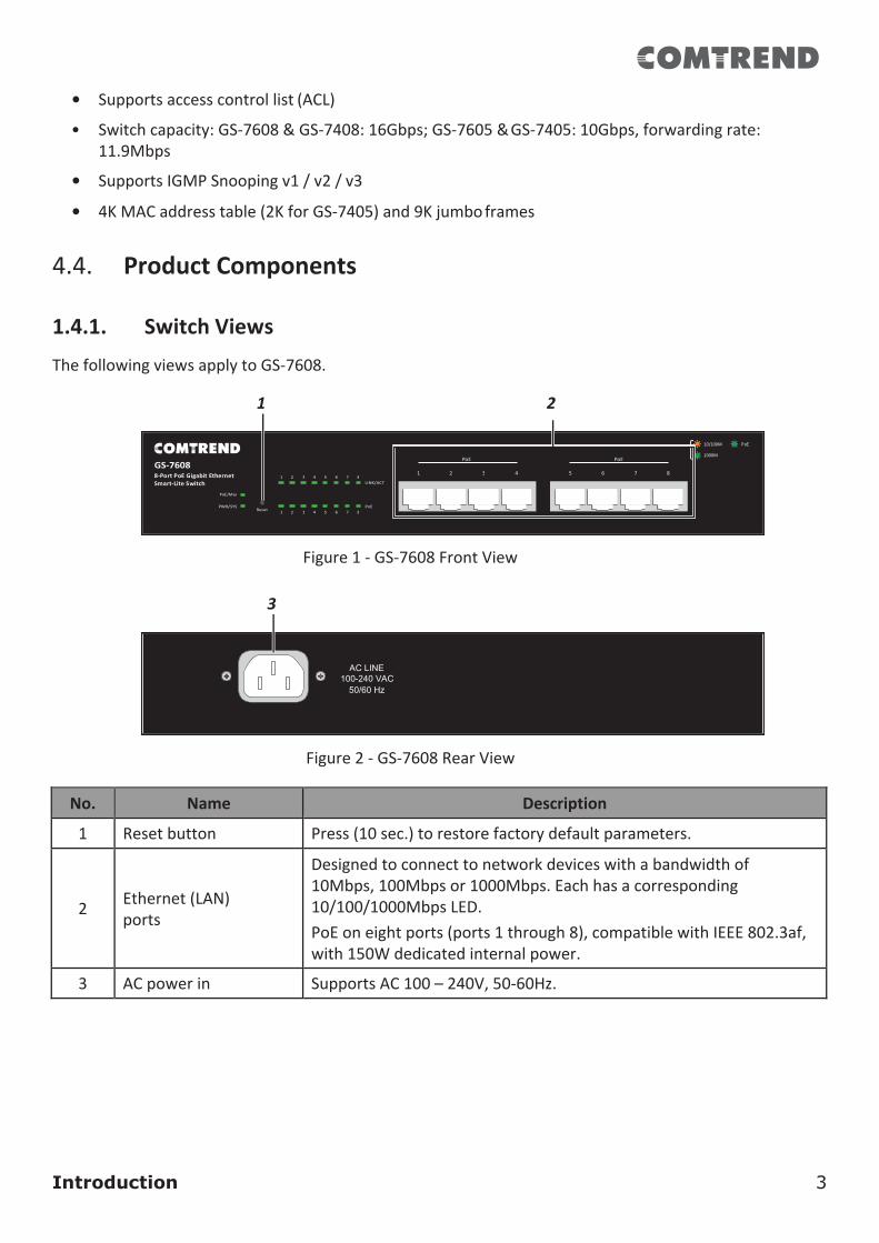
• 4KMACaddresstable(2KforGS-7405)and9Kjumboframes4.4. ProductComponents1.4.1. SwitchViewsThefollowingviewsapplytoGS-7608.
1 2
Figure1-GS-7608FrontView
3
Figure2-GS-7608RearView
No. Name Description
1 Resetbutton Press(10sec.)torestorefactorydefaultparameters.
2
Ethernet(LAN)ports
Designedtoconnecttonetworkdeviceswithabandwidthof10Mbps,100Mbpsor1000Mbps.Eachhasacorresponding10/100/1000MbpsLED.PoEoneightports(ports1through8),compatiblewithIEEE802.3af,with150Wdedicatedinternalpower.
3 ACpowerin SupportsAC100–240V,50-60Hz.
PoE PoE
PoE
AC LINE 100-240 VAC
50/60 Hz
Introduction 4
Reset
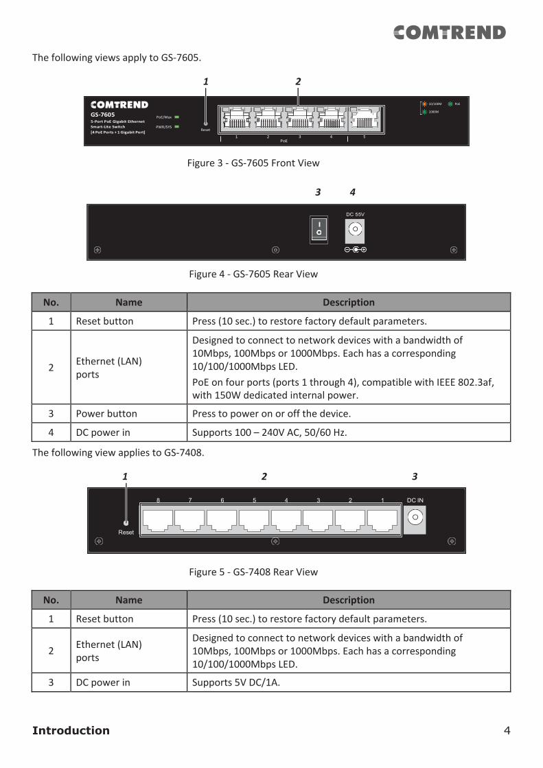
ThefollowingviewsapplytoGS-7605.
1 2
Figure3-GS-7605FrontView
3 4
Figure4-GS-7605RearView
No. Name Description
1 Resetbutton Press(10sec.)torestorefactorydefaultparameters.
2
Ethernet(LAN)ports
Designedtoconnecttonetworkdeviceswithabandwidthof10Mbps,100Mbpsor1000Mbps.Eachhasacorresponding10/100/1000MbpsLED.PoEonfourports(ports1through4),compatiblewithIEEE802.3af,with150Wdedicatedinternalpower.
3 Powerbutton Presstopoweronoroffthedevice.
4 DCpowerin Supports100–240VAC,50/60Hz.
ThefollowingviewappliestoGS-7408.
1 2 3
Figure5-GS-7408RearView
No. Name Description
1 Resetbutton Press(10sec.)torestorefactorydefaultparameters.
2 Ethernet(LAN)
ports
Designedtoconnecttonetworkdeviceswithabandwidthof10Mbps,100Mbpsor1000Mbps.Eachhasacorresponding10/100/1000MbpsLED.
3 DCpowerin Supports5VDC/1A.
PoE
PoE/Max
Reset
Introduction 5
Reset
PoE
PoE PoE
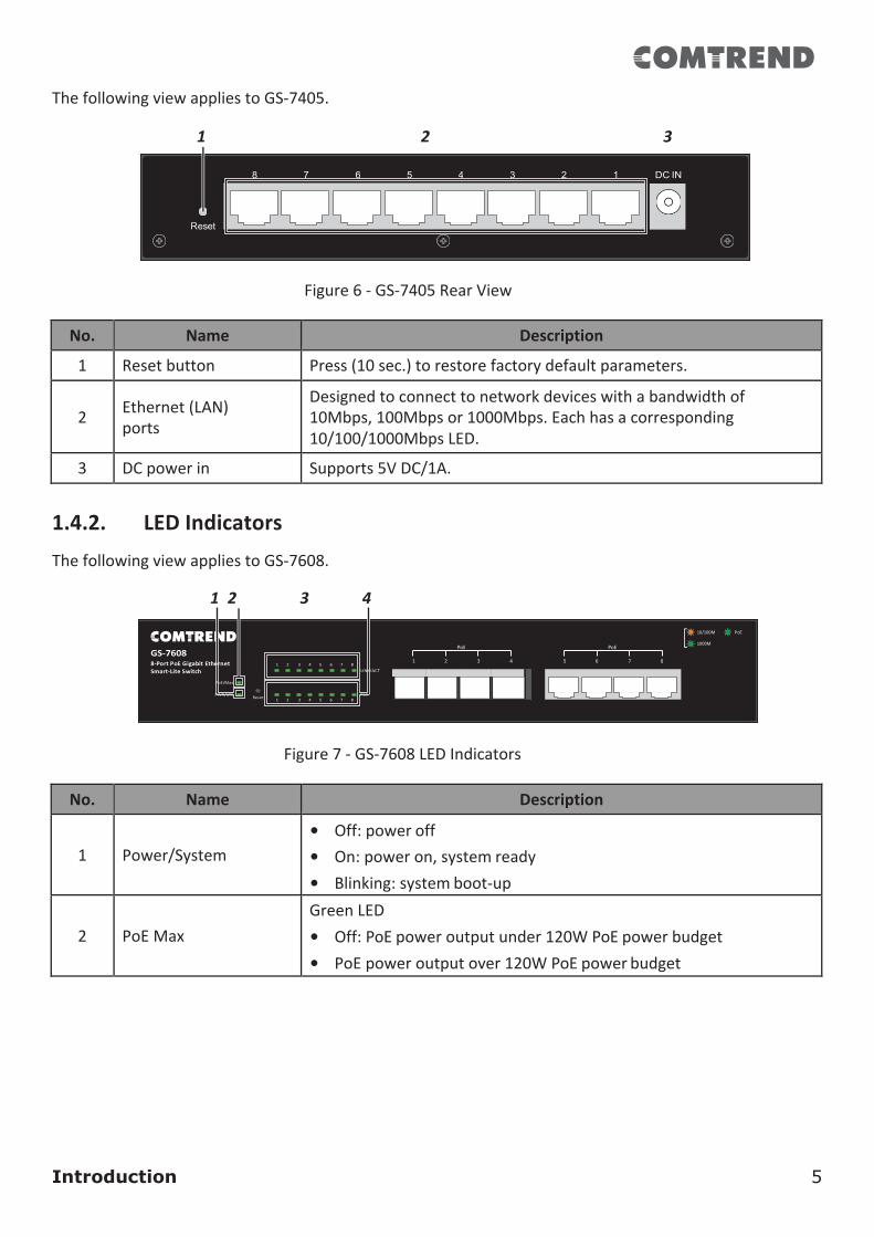
ThefollowingviewappliestoGS-7405.
1 2 3
Figure6-GS-7405RearView
No. Name Description
1 Resetbutton Press(10sec.)torestorefactorydefaultparameters.
2 Ethernet(LAN)
ports
Designedtoconnecttonetworkdeviceswithabandwidthof10Mbps,100Mbpsor1000Mbps.Eachhasacorresponding10/100/1000MbpsLED.
3 DCpowerin Supports5VDC/1A.
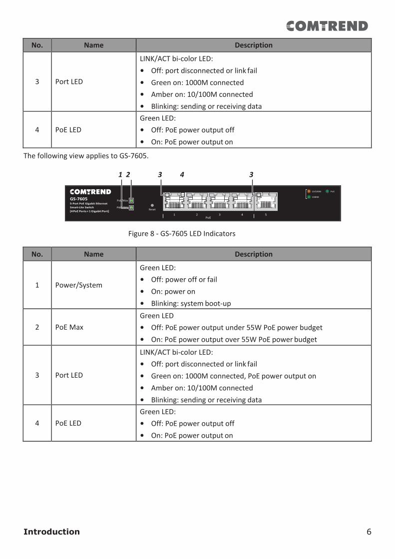
1.4.2. LEDIndicatorsThefollowingviewappliestoGS-7608.
1 2 3 4
Figure7-GS-7608LEDIndicators
No. Name Description
1
Power/System
• Off:poweroff• On:poweron,systemready• Blinking:systemboot-up
2
PoEMax
GreenLED• Off:PoEpoweroutputunder120WPoEpowerbudget• PoEpoweroutputover120WPoEpowerbudget
Introduction 6
No. Name Description
3
PortLED
LINK/ACTbi-colorLED:• Off:portdisconnectedorlinkfail• Greenon:1000Mconnected• Amberon:10/100Mconnected• Blinking:sendingorreceivingdata
4
PoELED
GreenLED:• Off:PoEpoweroutputoff• On:PoEpoweroutputon
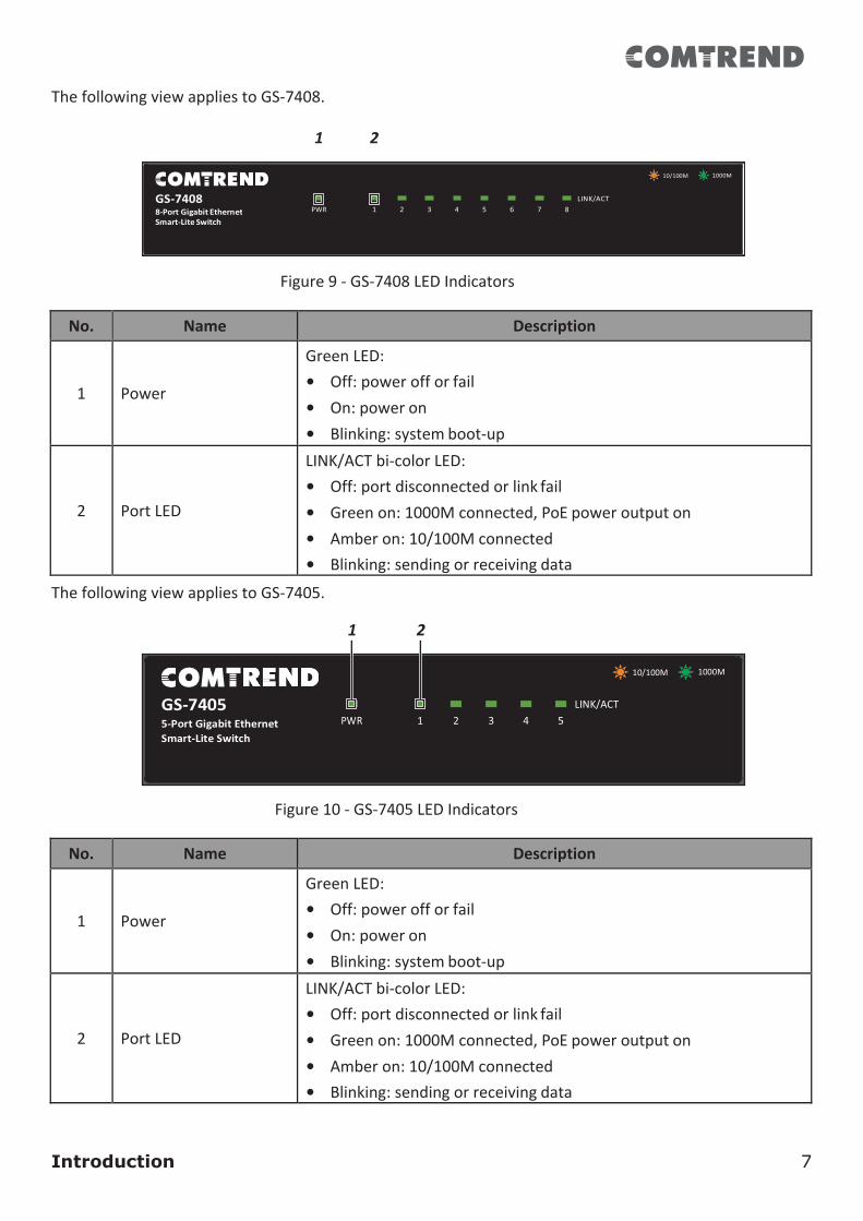
ThefollowingviewappliestoGS-7605.
1 2 3 4 3
Figure8-GS-7605LEDIndicators
No. Name Description
1
Power/System
GreenLED:• Off:powerofforfail• On:poweron• Blinking:systemboot-up
2
PoEMax
GreenLED• Off:PoEpoweroutputunder55WPoEpowerbudget• On:PoEpoweroutputover55WPoEpowerbudget
3
PortLED
LINK/ACTbi-colorLED:• Off:portdisconnectedorlinkfail• Greenon:1000Mconnected,PoEpoweroutputon• Amberon:10/100Mconnected• Blinking:sendingorreceivingdata
4
PoELED
GreenLED:• Off:PoEpoweroutputoff• On:PoEpoweroutputon
PoE/Max PWR/SYS
Reset
Introduction 7
ThefollowingviewappliestoGS-7408.
1 2
Figure9-GS-7408LEDIndicators
No. Name Description
1
Power
GreenLED:• Off:powerofforfail• On:poweron• Blinking:systemboot-up
2
PortLED
LINK/ACTbi-colorLED:• Off:portdisconnectedorlinkfail• Greenon:1000Mconnected,PoEpoweroutputon• Amberon:10/100Mconnected• Blinking:sendingorreceivingdata
ThefollowingviewappliestoGS-7405.
1 2
Figure10-GS-7405LEDIndicators
No. Name Description
1
Power
GreenLED:• Off:powerofforfail• On:poweron• Blinking:systemboot-up
2
PortLED
LINK/ACTbi-colorLED:• Off:portdisconnectedorlinkfail• Greenon:1000Mconnected,PoEpoweroutputon• Amberon:10/100Mconnected• Blinking:sendingorreceivingdata
PWR
10/100M 1000M
LINK/ACT
Installation 8
2. InstallationThischapterdescribeshowtoinstallandconnectyourComtrendSwitch.Readthefollowingtopicsandperformtheproceduresinthecorrectorder.Incorrectinstallationmaycausedamagetotheproduct.
Allmodelsaredesignedfordesktopuse,however,theGS-7608isavailablewitharackmountkit.1.1. PlacementTips
• AmbientTemperature—Topreventtheswitchfromoverheating,donotoperateitinanareathatexceedsanambienttemperatureof122°F(50°C).
• AirFlow—Besurethatthereisadequateairflowaroundtheswitch.
• MechanicalLoading—Besurethattheswitchislevelandstabletoavoidanyhazardousconditions.
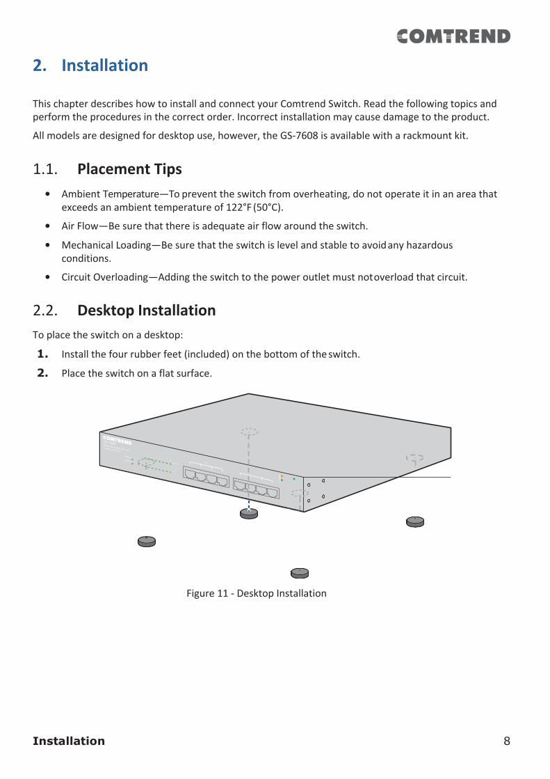
• CircuitOverloading—Addingtheswitchtothepoweroutletmustnotoverloadthatcircuit.2.2. DesktopInstallationToplacetheswitchonadesktop:
1. Installthefourrubberfeet(included)onthebottomoftheswitch.
2. Placetheswitchonaflatsurface.
Figure11-DesktopInstallation
Installation 9
3.3. Rack-MountInstallationOnlythefollowingdeviceisdesignedforarack-mountinstallation:GS-6708.
Youcanmounttheswitchinanystandardsize,19-inch(about48cm)widerack.Theswitchrequires1rackunit(RU)ofspace,whichis1.75inches(44.45mm)high.
Toplacetheswitchonastandardrack(1rackunithigh):
Forstability,loadtherackfromthebottomtothetop,withtheheaviestdevicesonthebottom.Atop-heavyrackislikelytobeunstableandmaytipover.Whenmountingsmallerswitchproductsintoastandard19-inchrack,apairofextensionbrackets(sometimesreferredtoasears)areneededtoadapttheswitchtotheracksize.Theseextensionbracketsaremountedontheswitchusingthescrewsprovidedinthekit,andhavetwoholesthatareusedtothenscrewtheswitchintotherack.Anexampleofonetypeoftheseextensionbracketsisshowninthefollowingfigure.Acommonproblemthatoccursduringrackmountingisthedistancebetweenthescrewholesontherack.Someracksaremadewithauniformdistancebetweenalloftheholes,andothershavetheholesorganizedintogroups(seephotoonthenextpageforanexample).Whenorganizedintogroups,theswitchmustbeplacedintheracksothattheholesintheextensionbracketslineupcorrectly.
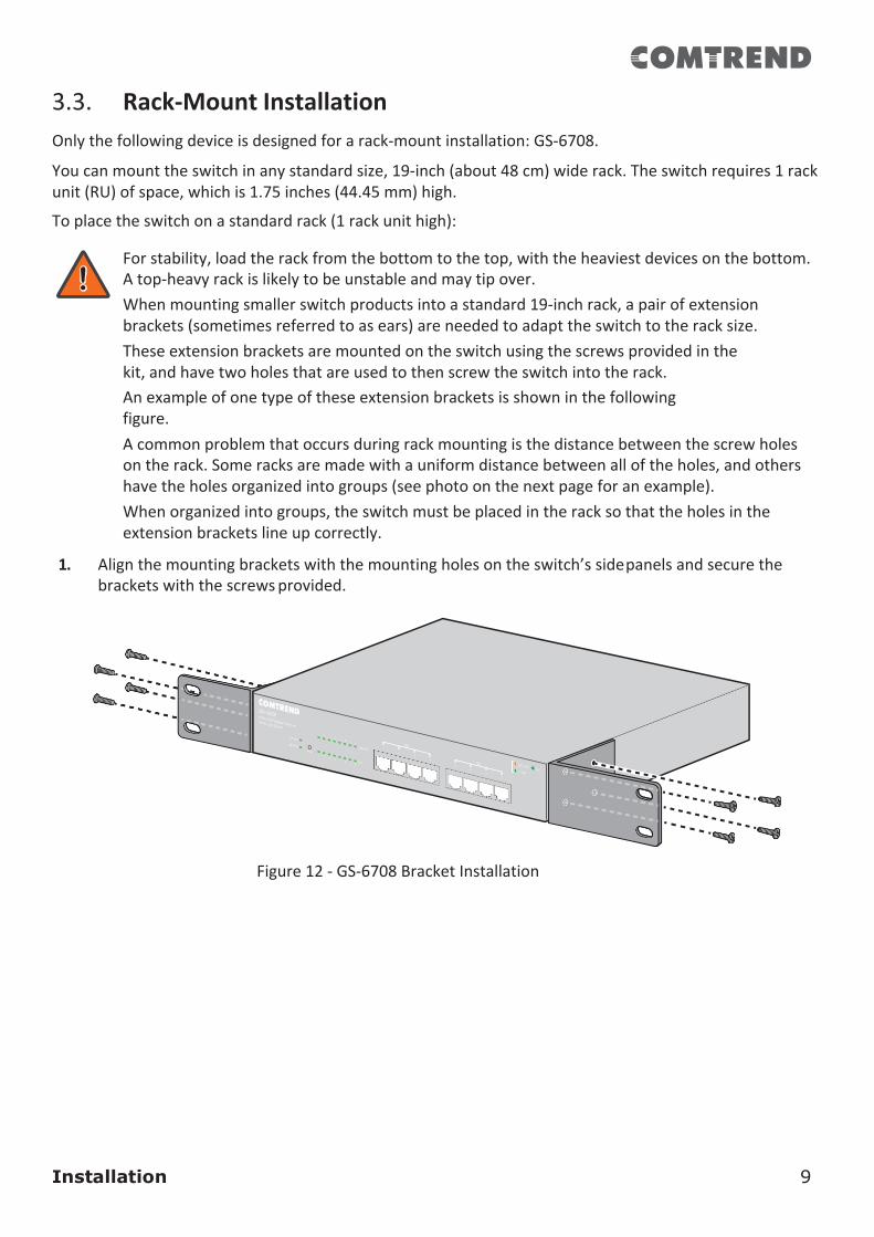
1. Alignthemountingbracketswiththemountingholesontheswitch’ssidepanelsandsecurethebracketswiththescrewsprovided.
Figure12-GS-6708BracketInstallation
Installation 10
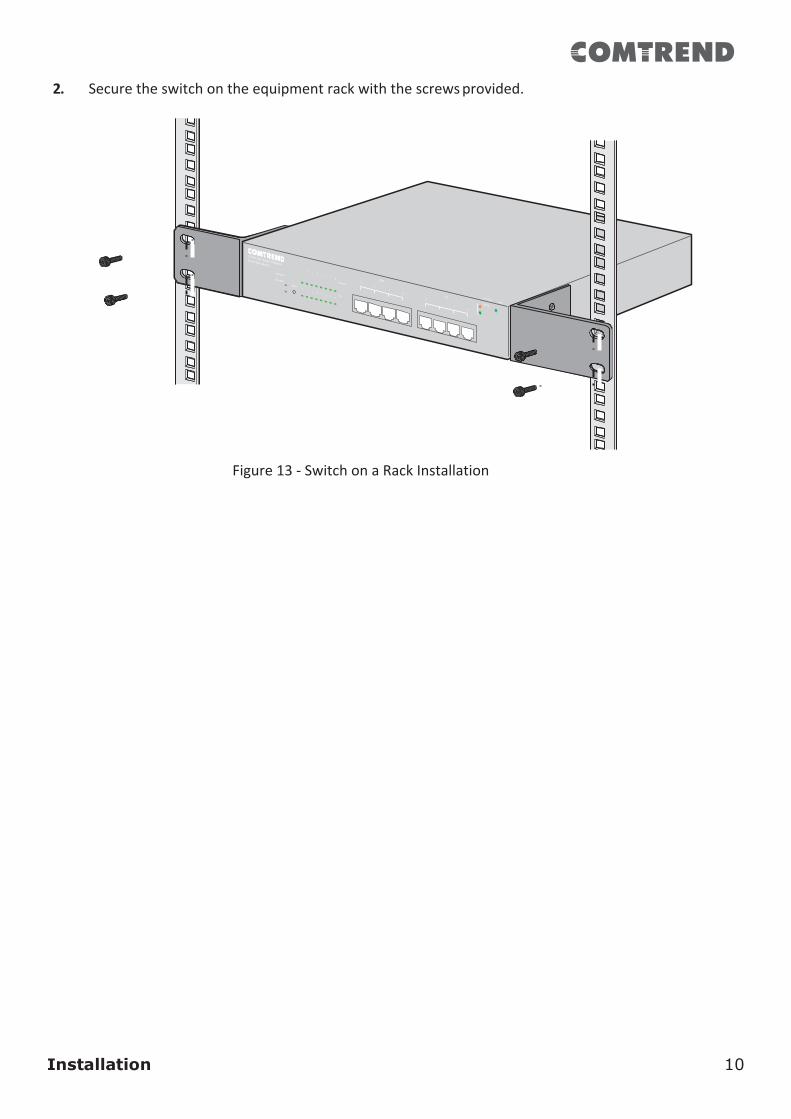
2. Securetheswitchontheequipmentrackwiththescrewsprovided.
Figure13-SwitchonaRackInstallation
Getting Started 11
3. GettingStartedThissectionprovidesanintroductiontotheweb-basedconfigurationutility,andcoversthefollowingtopics:
• Poweringonthedevice
• Connectingtothenetwork
• PoweroverEthernet(PoE)considerations
• Startingtheweb-basedconfigurationutility3.1. Power1.1.1. InstallingPower
Powerdownanddisconnectthepowercordbeforeservicingorwiringaswitch.
Donotdisconnectmodulesorcablingunlessthepowerisfirstswitchedoff.Thedeviceonlysupportsthevoltageoutlinedinthetypeplate.Donotuseanyotherpowercomponentsexceptthosespecificallydesignatedfortheswitch.
Disconnectthepowercordbeforeinstallationorcablewiring.TheGigabitEthernetSmart-Liteswitchesareavailablewithdifferentpoweroptionsfromaninternal(72W)PSUtoanexternal(150W)optionandpoweradapters(5VDC/1A).Itisrecommendedtoconnecttheswitchwithasingle-phasethree-wirepowersourcewithaneutraloutlet,oramultifunctionalcomputerprofessionalsource.
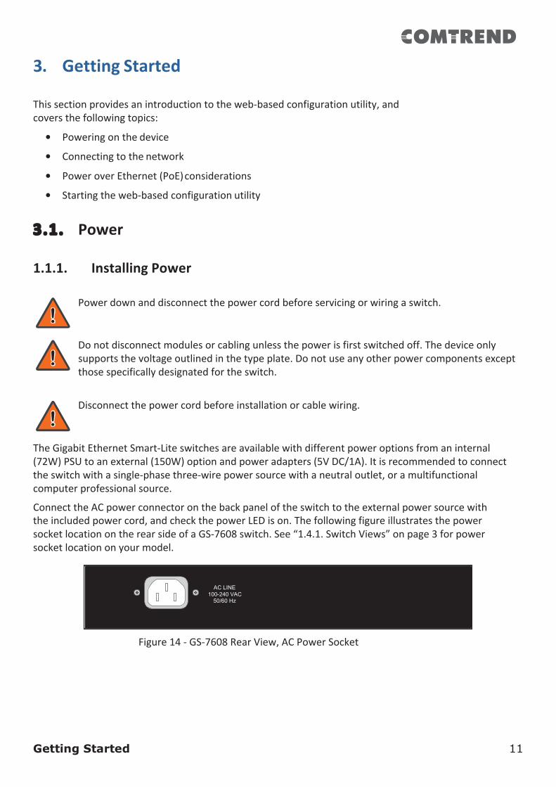
ConnecttheACpowerconnectoronthebackpaneloftheswitchtotheexternalpowersourcewiththeincludedpowercord,andcheckthepowerLEDison.ThefollowingfigureillustratesthepowersocketlocationontherearsideofaGS-7608switch.See“1.4.1.SwitchViews”onpage3forpowersocketlocationonyourmodel.
Figure14-GS-7608RearView,ACPowerSocket
AC LINE 100-240 VAC
50/60 Hz
Getting Started 12
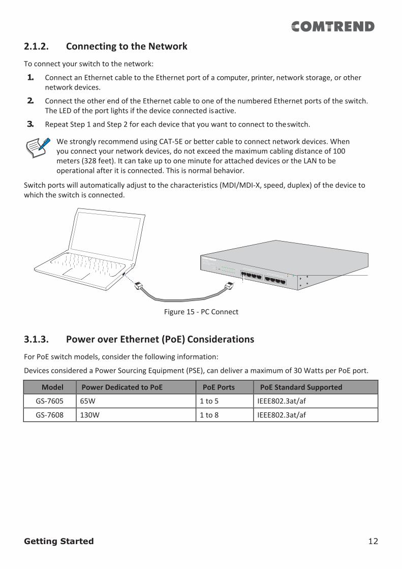
2.1.2. ConnectingtotheNetworkToconnectyourswitchtothenetwork:
1. ConnectanEthernetcabletotheEthernetportofacomputer,printer,networkstorage,orothernetworkdevices.
2. ConnecttheotherendoftheEthernetcabletooneofthenumberedEthernetportsoftheswitch.TheLEDoftheportlightsifthedeviceconnectedisactive.
3. RepeatStep1andStep2foreachdevicethatyouwanttoconnecttotheswitch.
WestronglyrecommendusingCAT-5Eorbettercabletoconnectnetworkdevices.Whenyouconnectyournetworkdevices,donotexceedthemaximumcablingdistanceof100meters(328feet).ItcantakeuptooneminuteforattacheddevicesortheLANtobeoperationalafteritisconnected.Thisisnormalbehavior.
Switchportswillautomaticallyadjusttothecharacteristics(MDI/MDI-X,speed,duplex)ofthedevicetowhichtheswitchisconnected.
Figure15-PCConnect
3.1.3. PoweroverEthernet(PoE)ConsiderationsForPoEswitchmodels,considerthefollowinginformation:
DevicesconsideredaPowerSourcingEquipment(PSE),candeliveramaximumof30WattsperPoEport.
Model PowerDedicatedtoPoE PoEPorts PoEStandardSupported
GS-7605 65W 1to5 IEEE802.3at/af
GS-7608 130W 1to8 IEEE802.3at/af
Getting Started 13
WhenconnectingswitchescapableofsupplyingPoE,considerthefollowinginformation:• SwitchmodelswithPoEfunctionarePSEs.ThesemodelsarecapableofsupplyingDC
powertoattachedPDs,suchasVoIPphones,IPcameras,andwirelessaccesspoints(APs).PoEswitches.Additionally,PoEswitchesarecapableofdetectingandsupplyingpowertopre-standardlegacyPoEPowerDevices.DuetothesupportforlegacyPoE,thereisapossibilitythatPoEswitchesactingasaPSEmayinadvertentlydetectandsupplypoweranattachedPSE,includingotherPoEswitches.ThisfalsedetectionmayresultinaPoEswitchoperatingimproperlyandunabletosupplypowertoattachedPDs.
• ThepreventionofafalsedetectioncanbeeasilyremediedbydisablingPoEontheportsthatareusedtoconnectPSEs.AnothersimplepracticetopreventafalsedetectionistofirstpowerupaPSEdevicebeforeconnectingittoaPoEswitch.
• Whena device is falsely detected as a PD,disconnect thedevice from thePoEport andpowerrecyclethedevicewithACpowerbeforereconnectingittothePoEport.
Getting Started 14
3.2. StartingtheWeb-basedConfigurationUtilityThissectiondescribeshowtonavigatetheweb-basedswitchconfigurationutility.
Ifyouareusingapop-upblocker,makesureitisdisabled.1.2.1. BrowserRestrictions
• IfyouareusingolderversionsofInternetExplorer,youcannotdirectlyuseanIPv6addresstoaccessthedevice.Youcan,however,usetheDNS(DomainNameSystem)servertocreateadomainnamethatcontainstheIPv6address,andthenusethatdomainnameintheaddressbarinplaceoftheIPv6address.
• IfyouhavemultipleIPv6interfacesonyourmanagementstation,usetheIPv6globaladdressinsteadoftheIPv6linklocaladdresstoaccessthedevicefromyourbrowser.
2.2.2. LaunchingtheConfigurationUtilityToopentheweb-basedconfigurationutility:
1. OpenaWebbrowser.
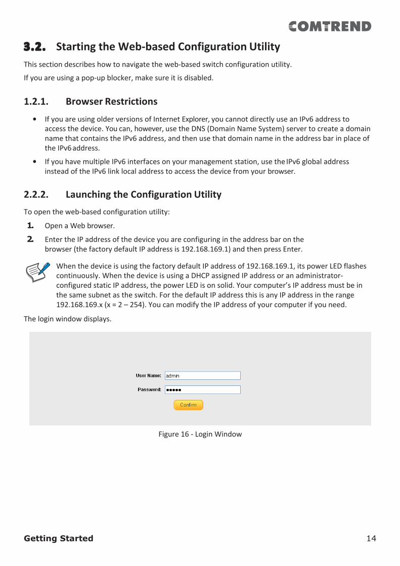
2. EntertheIPaddressofthedeviceyouareconfiguringintheaddressbaronthebrowser(thefactorydefaultIPaddressis192.168.169.1)andthenpressEnter.
WhenthedeviceisusingthefactorydefaultIPaddressof192.168.169.1,itspowerLEDflashescontinuously.WhenthedeviceisusingaDHCPassignedIPaddressoranadministrator-configuredstaticIPaddress,thepowerLEDisonsolid.Yourcomputer’sIPaddressmustbeinthesamesubnetastheswitch.ForthedefaultIPaddressthisisanyIPaddressintherange192.168.169.x(x=2–254).YoucanmodifytheIPaddressofyourcomputerifyouneed.
Theloginwindowdisplays.
Figure16-LoginWindow
Getting Started 15
3.2.3. LoggingIn
Thedefaultusernameisadminandthedefaultpasswordisadmin.Thefirsttimethatyouloginwiththedefaultusernameandpassword,youarerequiredtoenteranewpassword.
Tologintothedeviceconfigurationutility:
1. EnterthedefaultuserID(admin)andthedefaultpassword(admin).
2. IfthisisthefirsttimethatyouloggedonwiththedefaultuserID(admin)andthedefaultpassword(admin)itisrecommendedthatyouchangeyourpasswordimmediately.See“4.2.1.Password”onpage33foradditionalinformation.
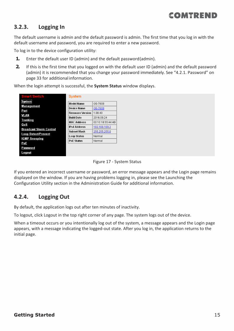
Whentheloginattemptissuccessful,theSystemStatuswindowdisplays.
Figure17-SystemStatusIfyouenteredanincorrectusernameorpassword,anerrormessageappearsandtheLoginpageremainsdisplayedonthewindow.Ifyouarehavingproblemsloggingin,pleaseseetheLaunchingtheConfigurationUtilitysectionintheAdministrationGuideforadditionalinformation.4.2.4. LoggingOutBydefault,theapplicationlogsoutaftertenminutesofinactivity.
Tologout,clickLogoutinthetoprightcornerofanypage.Thesystemlogsoutofthedevice.
Whenatimeoutoccursoryouintentionallylogoutofthesystem,amessageappearsandtheLoginpageappears,withamessageindicatingthelogged-outstate.Afteryoulogin,theapplicationreturnstotheinitialpage.
4. Web-basedSwitchConfigurationThePoESmart-LiteswitchsoftwareprovidesrichLayer2functionalityforswitchesinyournetworks.Thischapterdescribeshowtousetheweb-basedmanagementinterface(WebUI)toconfiguretheswitch’sfeatures.
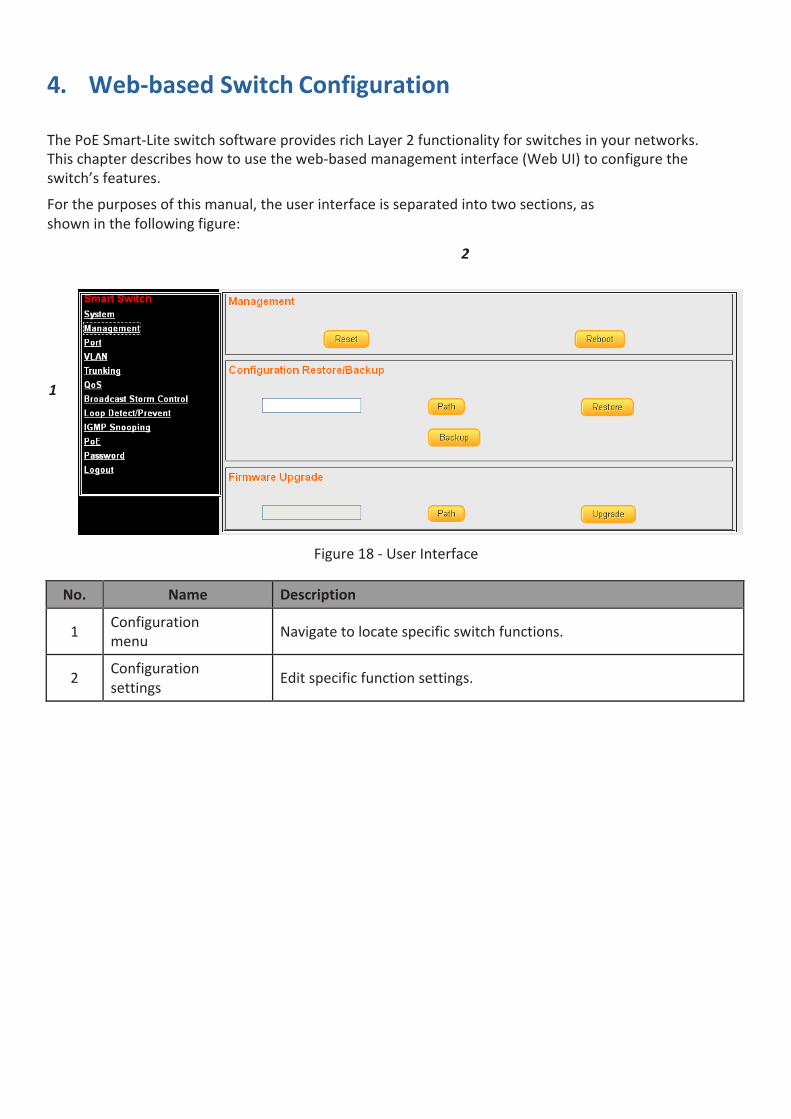
Forthepurposesofthismanual,theuserinterfaceisseparatedintotwosections,asshowninthefollowingfigure:
2
1
Figure18-UserInterface
No. Name Description
1 Configurationmenu Navigatetolocatespecificswitchfunctions.
2 Configurationsettings Editspecificfunctionsettings.
Web-based Switch Configuration 17
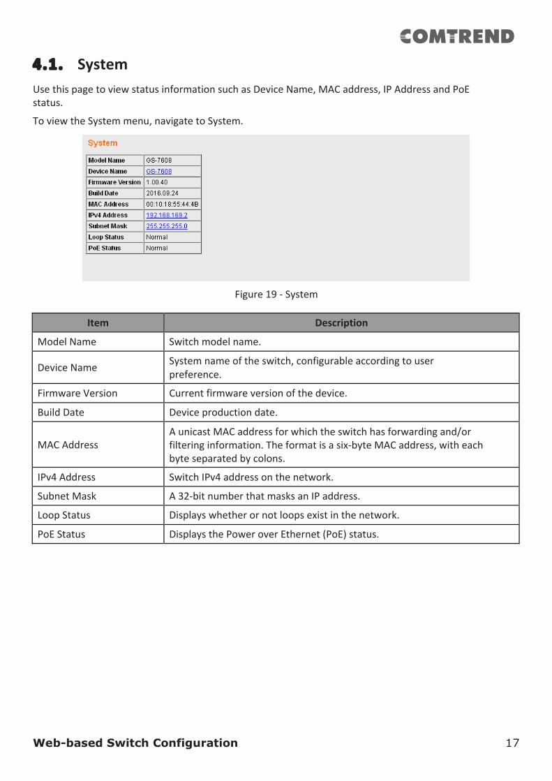
4.1. SystemUsethispagetoviewstatusinformationsuchasDeviceName,MACaddress,IPAddressandPoEstatus.
ToviewtheSystemmenu,navigatetoSystem.
Figure19-System
Item Description
ModelName Switchmodelname.
DeviceName Systemnameoftheswitch,configurableaccordingtouserpreference.
FirmwareVersion Currentfirmwareversionofthedevice.
BuildDate Deviceproductiondate.
MACAddress
AunicastMACaddressforwhichtheswitchhasforwardingand/orfilteringinformation.Theformatisasix-byteMACaddress,witheachbyteseparatedbycolons.
IPv4Address SwitchIPv4addressonthenetwork.
SubnetMask A32-bitnumberthatmasksanIPaddress.
LoopStatus Displayswhetherornotloopsexistinthenetwork.
PoEStatus DisplaysthePoweroverEthernet(PoE)status.
Web-based Switch Configuration 18
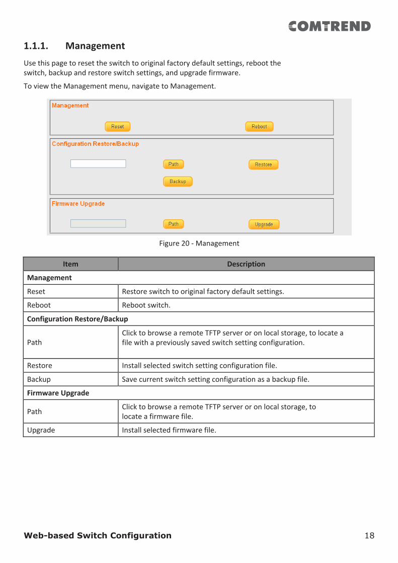
1.1.1. ManagementUsethispagetoresettheswitchtooriginalfactorydefaultsettings,reboottheswitch,backupandrestoreswitchsettings,andupgradefirmware.
ToviewtheManagementmenu,navigatetoManagement.
Figure20-Management
Item Description
Management
Reset Restoreswitchtooriginalfactorydefaultsettings.
Reboot Rebootswitch.
ConfigurationRestore/Backup
Path
ClicktobrowsearemoteTFTPserveroronlocalstorage,tolocateafilewithapreviouslysavedswitchsettingconfiguration.
Restore Installselectedswitchsettingconfigurationfile.
Backup Savecurrentswitchsettingconfigurationasabackupfile.
FirmwareUpgrade
Path ClicktobrowsearemoteTFTPserveroronlocalstorage,tolocateafirmwarefile.
Upgrade Installselectedfirmwarefile.
Web-based Switch Configuration 19
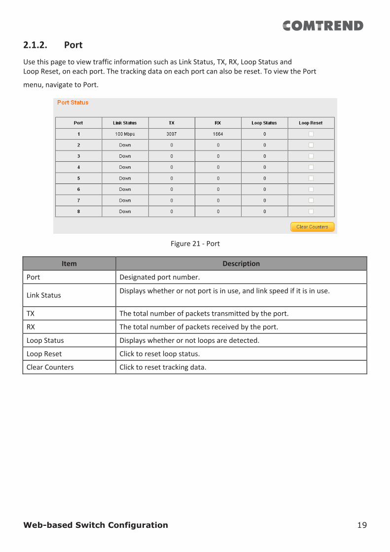
2.1.2. PortUsethispagetoviewtrafficinformationsuchasLinkStatus,TX,RX,LoopStatusandLoopReset,oneachport.Thetrackingdataoneachportcanalsobereset.ToviewthePort
menu,navigatetoPort.
Figure21-Port
Item Description
Port Designatedportnumber.
LinkStatus Displayswhetherornotportisinuse,andlinkspeedifitisinuse.
TX Thetotalnumberofpacketstransmittedbytheport.
RX Thetotalnumberofpacketsreceivedbytheport.
LoopStatus Displayswhetherornotloopsaredetected.
LoopReset Clicktoresetloopstatus.
ClearCounters Clicktoresettrackingdata.
Web-based Switch Configuration 20
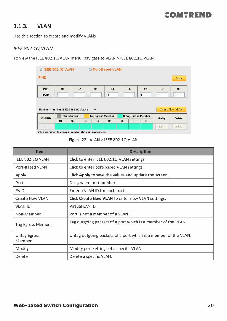
3.1.3. VLANUsethissectiontocreateandmodifyVLANs.IEEE802.1QVLAN
ToviewtheIEEE802.1QVLANmenu,navigatetoVLAN>IEEE802.1QVLAN.
Figure22-VLAN>IEEE802.1QVLAN
Item Description
IEEE802.1QVLAN ClicktoenterIEEE802.1QVLANsettings.
Port-BasedVLAN Clicktoenterport-basedVLANsettings.
Apply ClickApplytosavethevaluesandupdatethescreen.
Port Designatedportnumber.
PVID EnteraVLANIDforeachport.
CreateNewVLAN ClickCreateNewVLANtoenternewVLANsettings.
VLANID VirtualLANID.
Non-Member PortisnotamemberofaVLAN.
TagEgressMember TagoutgoingpacketsofaportwhichisamemberoftheVLAN.
UntagEgressMember
UntagoutgoingpacketsofaportwhichisamemberoftheVLAN.
Modify ModifyportsettingsofaspecificVLAN.
Delete DeleteaspecificVLAN.
Web-based Switch Configuration 21
Port-BasedVLAN
ToviewthePort-BasedVLANmenu,navigatetoVLAN>Port-BasedVLAN.
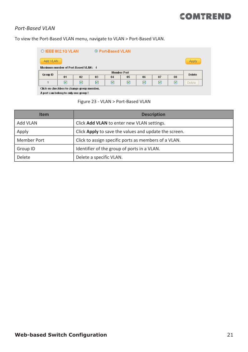
Figure23-VLAN>Port-BasedVLAN
Item Description
AddVLAN ClickAddVLANtoenternewVLANsettings.
Apply ClickApplytosavethevaluesandupdatethescreen.
MemberPort ClicktoassignspecificportsasmembersofaVLAN.
GroupID IdentifierofthegroupofportsinaVLAN.
Delete DeleteaspecificVLAN.
Web-based Switch Configuration 22
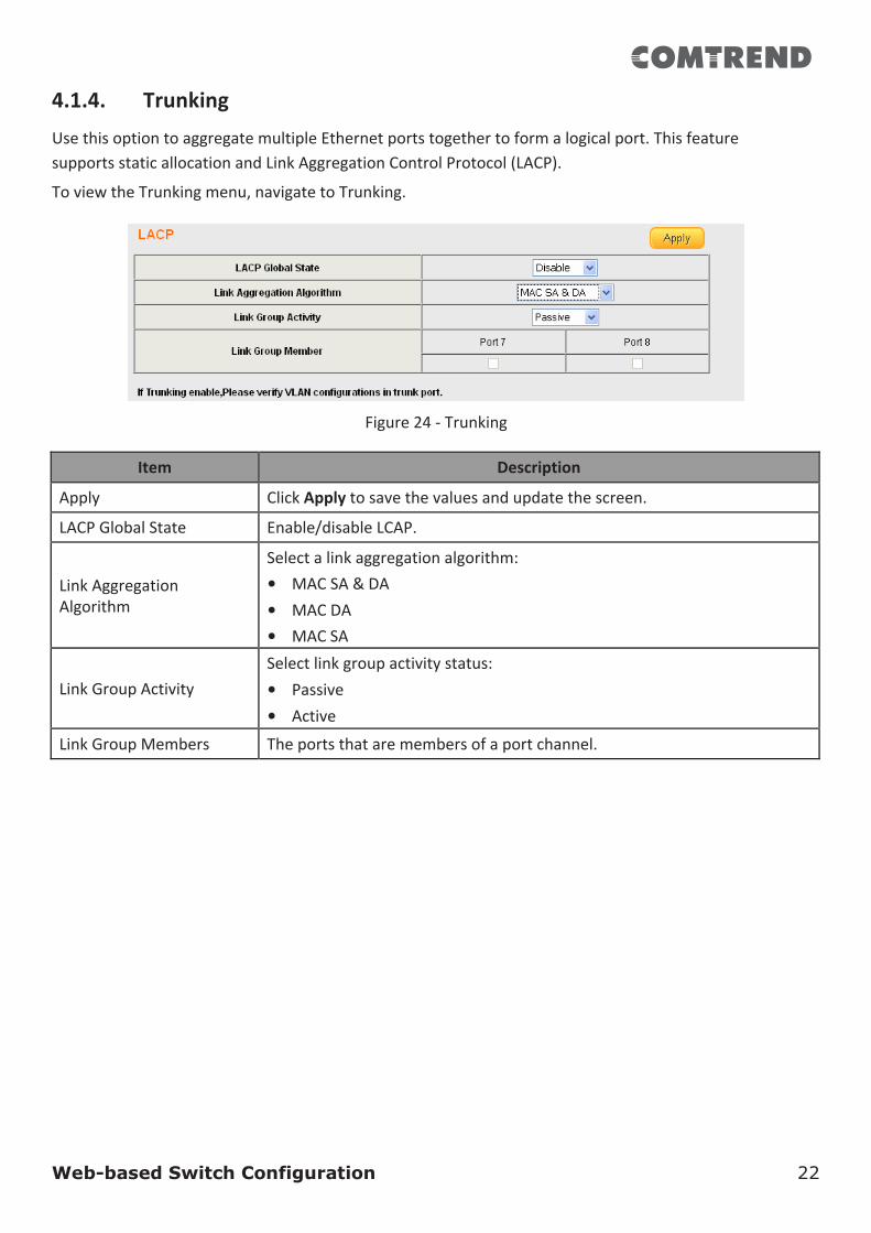
4.1.4. TrunkingUsethisoptiontoaggregatemultipleEthernetportstogethertoformalogicalport.ThisfeaturesupportsstaticallocationandLinkAggregationControlProtocol(LACP).
ToviewtheTrunkingmenu,navigatetoTrunking.
Figure24-Trunking
Item Description
Apply ClickApplytosavethevaluesandupdatethescreen.
LACPGlobalState Enable/disableLCAP.
LinkAggregationAlgorithm
Selectalinkaggregationalgorithm:• MACSA&DA• MACDA• MACSA
LinkGroupActivity
Selectlinkgroupactivitystatus:• Passive• Active
LinkGroupMembers Theportsthataremembersofaportchannel.
Web-based Switch Configuration 23
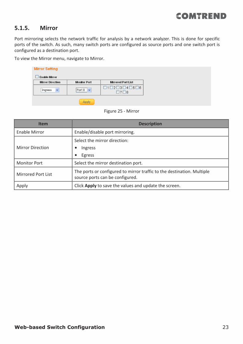
5.1.5. Mirror
Portmirroringselectsthenetworktraffic foranalysisbyanetworkanalyzer.This isdoneforspecificportsoftheswitch.Assuch,manyswitchportsareconfiguredassourceportsandoneswitchportisconfiguredasadestinationport.
ToviewtheMirrormenu,navigatetoMirror.
Figure25-Mirror
Item Description
EnableMirror Enable/disableportmirroring.
MirrorDirection
Selectthemirrordirection:• Ingress• Egress
MonitorPort Selectthemirrordestinationport.
MirroredPortList Theportsorconfiguredtomirrortraffictothedestination.Multiplesourceportscanbeconfigured.
Apply ClickApplytosavethevaluesandupdatethescreen.
Web-based Switch Configuration 24
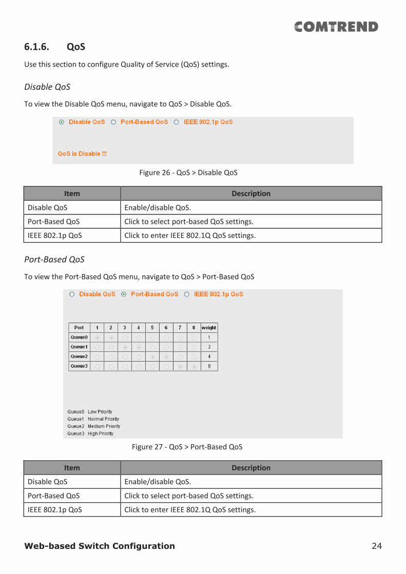
6.1.6. QoSUsethissectiontoconfigureQualityofService(QoS)settings.DisableQoS
ToviewtheDisableQoSmenu,navigatetoQoS>DisableQoS.
Figure26-QoS>DisableQoS
Item Description
DisableQoS Enable/disableQoS.
Port-BasedQoS Clicktoselectport-basedQoSsettings.
IEEE802.1pQoS ClicktoenterIEEE802.1QQoSsettings.
Port-BasedQoS
ToviewthePort-BasedQoSmenu,navigatetoQoS>Port-BasedQoS
Figure27-QoS>Port-BasedQoS
Item Description
DisableQoS Enable/disableQoS.
Port-BasedQoS Clicktoselectport-basedQoSsettings.
IEEE802.1pQoS ClicktoenterIEEE802.1QQoSsettings.

Web-based Switch Configuration 25
Item Description
Port Designatedportnumber.
Weight Queuepriorityvalue.Morepacketsaresentfromaqueuewithahigherweightvalue.
Queue0-3 Queuesusedtostoretrafficuntilitcanbeprocessedorserialized.
IEEE802.1pQoS
ToviewtheIEEE802.1pQoSmenu,navigatetoQoS>IEEE802.1pQoS.
Figure28-QoS>IEEE802.1pQoS
Item Description
DisableQoS Enable/disableQoS.
Port-BasedQoS Clicktoselectport-basedQoSsettings.
IEEE802.1pQoS ClicktoenterIEEE802.1QQoSsettings.
Port Designatedportnumber.
Weight Queuepriorityvalue.Morepacketsaresentfromaqueuewithahigherweightvalue.
Queue0-3 Queuesusedtostoretrafficuntilitcanbeprocessedorserialized.
Web-based Switch Configuration 26
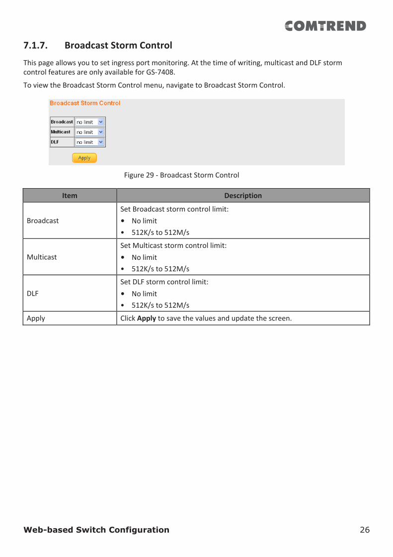
7.1.7. BroadcastStormControl
Thispageallowsyoutosetingressportmonitoring.Atthetimeofwriting,multicastandDLFstormcontrolfeaturesareonlyavailableforGS-7408.
ToviewtheBroadcastStormControlmenu,navigatetoBroadcastStormControl.
Figure29-BroadcastStormControl
Item Description
Broadcast
SetBroadcaststormcontrollimit:• Nolimit• 512K/sto512M/s
Multicast
SetMulticaststormcontrollimit:• Nolimit• 512K/sto512M/s
DLF
SetDLFstormcontrollimit:• Nolimit• 512K/sto512M/s
Apply ClickApplytosavethevaluesandupdatethescreen.
Web-based Switch Configuration 27
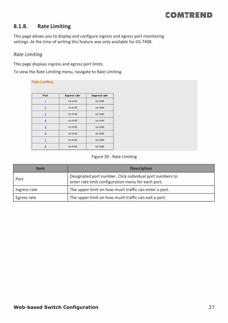
8.1.8. RateLimitingThispageallowsyoutodisplayandconfigureingressandegressportmonitoringsettings.AtthetimeofwritingthisfeaturewasonlyavailableforGS-7408.RateLimiting
Thispagedisplaysingressandegressportlimits.
ToviewtheRateLimitingmenu,navigatetoRateLimiting.
Figure30-RateLimiting
Item Description
Port Designatedportnumber.Clickindividualportnumberstoenterratelimitconfigurationmenuforeachport.
Ingressrate Theupperlimitonhowmuchtrafficcanenteraport.
Egressrate Theupperlimitonhowmuchtrafficcanexitaport.
Web-based Switch Configuration 28
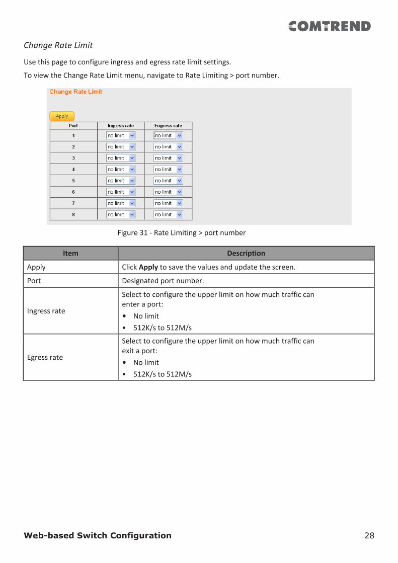
ChangeRateLimit
Usethispagetoconfigureingressandegressratelimitsettings.
ToviewtheChangeRateLimitmenu,navigatetoRateLimiting>portnumber.
Figure31-RateLimiting>portnumber
Item Description
Apply ClickApplytosavethevaluesandupdatethescreen.
Port Designatedportnumber.Ingressrate
Selecttoconfiguretheupperlimitonhowmuchtrafficcanenteraport:• Nolimit• 512K/sto512M/s
Egressrate
Selecttoconfiguretheupperlimitonhowmuchtrafficcanexitaport:• Nolimit• 512K/sto512M/s
Web-based Switch Configuration 29
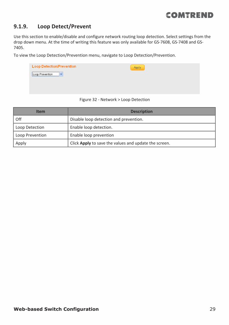
9.1.9. LoopDetect/Prevent
Usethissectiontoenable/disableandconfigurenetworkroutingloopdetection.Selectsettingsfromthedropdownmenu.AtthetimeofwritingthisfeaturewasonlyavailableforGS-7608,GS-7408andGS-7405.
ToviewtheLoopDetection/Preventionmenu,navigatetoLoopDetection/Prevention.
Figure32-Network>LoopDetection
Item Description
Off Disableloopdetectionandprevention.
LoopDetection Enableloopdetection.
LoopPrevention Enableloopprevention
Apply ClickApplytosavethevaluesandupdatethescreen.
Web-based Switch Configuration 30
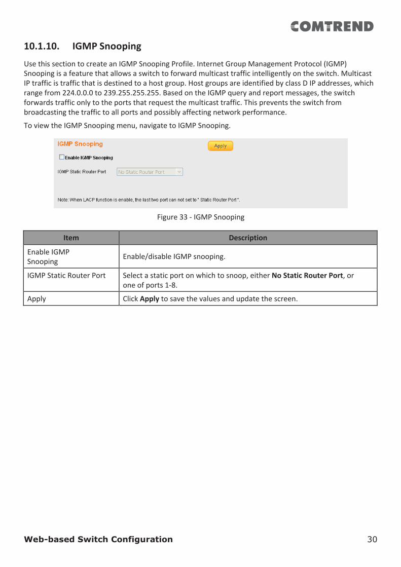
10.1.10. IGMPSnooping
UsethissectiontocreateanIGMPSnoopingProfile.InternetGroupManagementProtocol(IGMP)Snoopingisafeaturethatallowsaswitchtoforwardmulticasttrafficintelligentlyontheswitch.MulticastIPtrafficistrafficthatisdestinedtoahostgroup.HostgroupsareidentifiedbyclassDIPaddresses,whichrangefrom224.0.0.0to239.255.255.255.BasedontheIGMPqueryandreportmessages,theswitchforwardstrafficonlytotheportsthatrequestthemulticasttraffic.Thispreventstheswitchfrombroadcastingthetraffictoallportsandpossiblyaffectingnetworkperformance.
ToviewtheIGMPSnoopingmenu,navigatetoIGMPSnooping.
Figure33-IGMPSnooping
Item Description
EnableIGMPSnooping Enable/disableIGMPsnooping.
IGMPStaticRouterPort Selectastaticportonwhichtosnoop,eitherNoStaticRouterPort,oroneofports1-8.
Apply ClickApplytosavethevaluesandupdatethescreen.
Web-based Switch Configuration 31
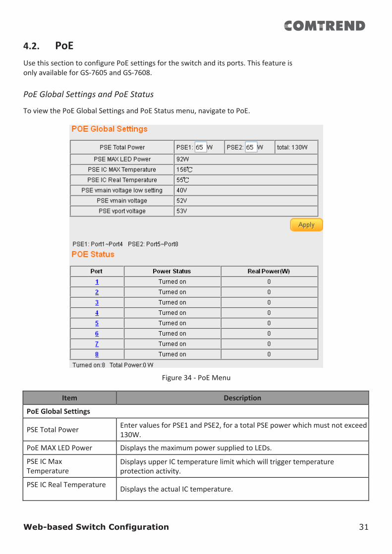
4.2. PoEUsethissectiontoconfigurePoEsettingsfortheswitchanditsports.ThisfeatureisonlyavailableforGS-7605andGS-7608.PoEGlobalSettingsandPoEStatus
ToviewthePoEGlobalSettingsandPoEStatusmenu,navigatetoPoE.
Figure34-PoEMenu
Item Description
PoEGlobalSettings
PSETotalPower EntervaluesforPSE1andPSE2,foratotalPSEpowerwhichmustnotexceed130W.
PoEMAXLEDPower DisplaysthemaximumpowersuppliedtoLEDs.
PSEICMaxTemperature
DisplaysupperICtemperaturelimitwhichwilltriggertemperatureprotectionactivity.
PSEICRealTemperature DisplaystheactualICtemperature.
Web-based Switch Configuration 32
Item Description
PSEvmainvoltagelowsetting
DisplaysthelowerlimitforthePSEmainvoltage.
PSEvmainvoltage DisplaystherealPSEmainvoltage.
PSEvportvoltage Displaysvoltagesuppliedtoports.
Apply ClickApplytosavethevaluesandupdatethescreen.
PoEStatus
Port Designatedportnumber.ClickindividualportnumberstoenterPoEportconfigurationmenuforeachport.
PowerStatus Displayscurrentportpowerstatus,onoroff.
RealPower(W) Displayspowerdrawnbytheport,inWatts.
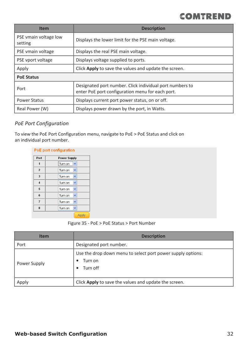
PoEPortConfiguration
ToviewthePoEPortConfigurationmenu,navigatetoPoE>PoEStatusandclickonanindividualportnumber.
Figure35-PoE>PoEStatus>PortNumber
Item Description
Port Designatedportnumber.PowerSupply
Usethedropdownmenutoselectportpowersupplyoptions:• Turnon• Turnoff
Apply ClickApplytosavethevaluesandupdatethescreen.
Web-based Switch Configuration 33
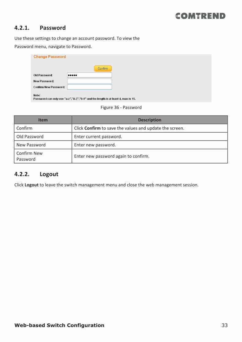
4.2.1. PasswordUsethesesettingstochangeanaccountpassword.Toviewthe
Passwordmenu,navigatetoPassword.
Figure36-Password
Item Description
Confirm ClickConfirmtosavethevaluesandupdatethescreen.
OldPassword Entercurrentpassword.
NewPassword Enternewpassword.
ConfirmNewPassword Enternewpasswordagaintoconfirm.
4.2.2. Logout
ClickLogouttoleavetheswitchmanagementmenuandclosethewebmanagementsession.
Federal Communication Commission Interference Statement 34
5. FederalCommunicationCommissionInterferenceStatement
ThisequipmenthasbeentestedandfoundtocomplywiththelimitsforaClassBdigitaldevice,pursuanttoPart15ofFCCRules.Theselimitsaredesignedtoprovidereasonableprotectionagainstharmfulinterferenceinaresidentialinstallation.Thisequipmentgenerates,uses,andcanradiateradiofrequencyenergyand,ifnotinstalledandusedinaccordancewiththeinstructions,maycauseharmfulinterferencetoradiocommunications.However,thereisnoguaranteethatinterferencewillnotoccurinaparticularinstallation.Ifthisequipmentdoescauseharmfulinterferencetoradioortelevisionreception,whichcanbedeterminedbyturningtheequipmentoffandon,theuserisencouragedtotrytocorrecttheinterferencebyoneormoreofthefollowingmeasures:
1. Reorientorrelocatethereceivingantenna.
2. Increasetheseparationbetweentheequipmentandreceiver.
3. Connecttheequipmentintoanoutletonacircuitdifferentfromthattowhichthereceiverisconnected.
4. Consultthedealeroranexperiencedradiotechnicianforhelp.SafetyThisequipmentisdesignedwiththeutmostcareforthesafetyofthosewhoinstallanduseit.However,specialattentionmustbepaidtothedangersofelectricshockandstaticelectricitywhenworkingwithelectricalequipment.Allguidelinesofthisandofthecomputermanufacturemustthereforebeallowedatalltimestoensurethesafeuseoftheequipment.FCCCautionThisdeviceanditsantennamustnotbeco-locatedoroperatinginconjunctionwithanyotherantennaortransmitter.ThisdevicecomplieswithPart15oftheFCCRules.Operationissubjecttothefollowingtwoconditions:(1)thisdevicemaynotcauseharmfulinterference,and(2)thisdevicemustacceptanyinterferencereceived,includinginterferencethatmaycauseundesiredoperation.Anychangesormodificationsnotexpresslyapprovedbythepartyresponsibleforcompliancecouldvoidtheauthoritytooperateequipment.FCCRadiationExposureStatementThisequipmentcomplieswithFCCradiationexposurelimitssetforthforanuncontrolledenvironment.Thisequipmentshouldbeinstalledandoperatedwithminimumdistance20cmbetweentheradiator&yourbody.

R&TTEComplianceStatementThisequipmentcomplieswithalltherequirementsofDIRECTIVE1999/5/ECOFTHEEUROPEANPARLIAMENTANDTHECOUNCILofMarch9,1999onradioequipmentandtelecommunicationterminalequipmentandthemutualrecognitionoftheirconformity(R&TTE).TheR&TTEDirectiverepealsandreplacesinthedirective98/13/EEC(TelecommunicationsTerminalEquipmentandSatelliteEarthStationEquipment)AsofApril8,2000.EUCountriesIntendedforUseTheETSIversionofthisdeviceisintendedforhomeandofficeuseinAustria,Belgium,Bulgaria,Cyprus,Czech,Denmark,Estonia,Finland,France,Germany,Greece,Hungary,Ireland,Italy,Latvia,Lithuania,Luxembourg,Malta,Netherlands,Poland,Portugal,Romania,Slovakia,Slovenia,Spain,Sweden,Turkey,andUnitedKingdom.TheETSIversionofthisdeviceisalsoauthorizedforuseinEFTAmemberstates:Iceland,Liechtenstein,Norway,andSwitzerland.EUCountriesNotIntendedforUseNone
ProtectOurEnvironment
Whentheequipmenthasreachedtheendofitsusefullife,itmustbetakentoarecyclingcenterandprocessedseparatefromdomesticwaste.
Thecardboardbox,theplasticcontainedinthepackaging,andthepartsthatmakeupthisswitchcanberecycledinaccordancewithregionallyestablishedregulations.Neverdisposeofthiselectronicequipmentalongwithyourhouseholdwaste;youmaybesubjecttopenaltiesorsanctionsunderthelaw.

Copyright©2016ComtrendCorporation.Allrightsreserved.Nopartofthispublicationmaybereproduced,transmitted,transcribed,storedinaretrievalsystem,ortranslatedintoanylanguageorcomputerlanguage,inanyformorbyanymeanswithoutthepriorwrittenpermissionofComtrendCorporation.ComtrendCorporationmakesnorepresentationsorwarranties,eitherexpressedorimplied,withrespecttothecontentshereofandspecificallydisclaimsanywarranties,merchantabilityorfitnessforanyparticularpurpose.Anysoftwaredescribedinthismanualissoldorlicensed“asis”.Shouldtheprogramsprovedefectivefollowingtheirpurchase,thebuyer(andnotComtrendCorporation,itsdistributors,oritsdealers)assumestheentirecostofallnecessaryservicing,repair,andanyincidentalorconsequentialdamagesresultingfromanydefectinthesoftware.Further,ComtrendCorporationreservestherighttorevisethispublicationandtomakechangesfromtimetotimeinthecontentsthereofwithoutobligationtonotifyanypersonofsuchrevisionorchanges.
SeetheGNUGeneralPublicLicenseformoredetails.
YoushouldhavereceivedacopyoftheGNUGeneralPublicLicensealongwiththisprogram.Ifnot,seehttp://www.gnu.org/licenses/.
Thisdocumentissubjecttochangewithoutnotice.