Embed Size (px)
Citation preview
Santa Clara UniversityScholar Commons
Interdisciplinary Design Senior Theses Engineering Senior Theses
6-8-2015
Might-E WheelAbigail GrillsSanta Clara University
Daniel DokeSanta Clara University
Jared O'RourkeSanta Clara University
Zach JesbergerSanta Clara University
Follow this and additional works at: https://scholarcommons.scu.edu/idp_senior
Part of the Electrical and Computer Engineering Commons, and the Mechanical EngineeringCommons
This Thesis is brought to you for free and open access by the Engineering Senior Theses at Scholar Commons. It has been accepted for inclusion inInterdisciplinary Design Senior Theses by an authorized administrator of Scholar Commons. For more information, please contact [email protected].
Recommended CitationGrills, Abigail; Doke, Daniel; O'Rourke, Jared; and Jesberger, Zach, "Might-E Wheel" (2015). Interdisciplinary Design Senior Theses. 11.https://scholarcommons.scu.edu/idp_senior/11
MIGHT-E WHEEL
By
Abigail Grills, Daniel Doke, Jared O’Rourke, and Zach Jesberger
SENIOR DESIGN PROJECT REPORT
Submitted to
The Departments of Mechanical & Electrical Engineering
of
SANTA CLARA UNIVERSITY
in Partial Fulfillment of the Requirements for the Degrees of
Bachelor of Science in Mechanical & Electrical Engineering
Santa Clara, California
June 8, 2015
iii
Might-E Wheel
Abigail Grills, Daniel Doke, Jared O’Rourke, and Zach Jesberger
Departments of Mechanical & Electrical Engineering
Santa Clara University 2015
ABSTRACT Electric bikes are proving to be an increasingly reliable source of transportation, but with large price tags and existing conversion kits proving too complicated and unapproachable for the average user, commuters are failing to consider electric bicycles as an option. A prototype of a wireless, rear-wheel replacement to convert a bicycle from manual to full-power electric was built. This motorized wheel is called Might-E Wheel. Might-E Wheel was designed as the most approachable and user-friendly way to convert a bicycle from manual to full-power electric. Might-E Wheel was able to achieve a top speed of 27.5 km/h, a range of 24.6 km, and run at 311 W of power. Range tests were inconclusive. The fully assembled system weighed 6.8 kg. The system was found to adequately meet the goals of the project. Battery failure limited the testing of Might-E Wheel, but the system was found to run smoothly before the failure, which was unrelated to the system design. In the future, further tests are planned with new batteries. Also, further development of the product is desired in order to lower the weight and reduce the size of the system. Ideally, the next prototype of the system would consist of a custom built motor and a fully-enclosed system within the hub of the wheel. Keywords: Electric Bicycles, Transportation, Green Technologies
iv
Acknowledgements Many individuals and groups deserve acknowledgement for assistance in this project. The Santa Clara University Undergraduate Senior Design Grant and the Center for Science, Technology, and Society’s Roelandts Grant funded the project. Dr. Robert Marks and Dr. Timothy Healy, the project advisors, assisted the entire project from conception to construction to the writing of the thesis. Dr. Jacquelyn Hendricks, the project’s English professor, assisted heavily with the initial research and formatting of the thesis. Other professors that assisted in the engineering of the project include Dr. Timothy Hight, Dr. Scott Abrahamson, and Dr. Christopher Kitts. Don Maccubbin and Calvin Sellers, the Santa Clara University machine shop managers, assisted heavily in the construction of the project. External names and organizations that deserve acknowledgement include Good Karma Bikes, ELV Motors, Arman Toorian, and Chris Yu of Specialized Bikes. Thank you to all the people listed here; this project could not have been completed without them.
v
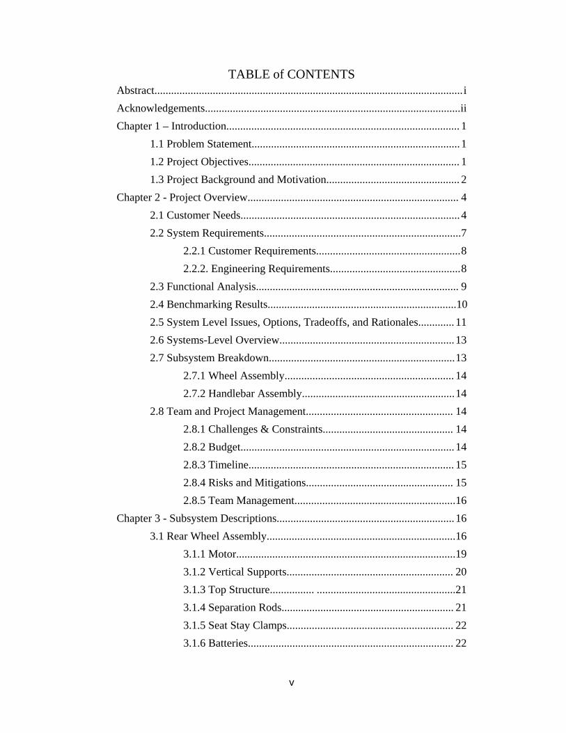
TABLE of CONTENTS Abstract............................................................................................................... i Acknowledgements............................................................................................ ii Chapter 1 – Introduction.................................................................................... 1
1.1 Problem Statement........................................................................... 1
1.2 Project Objectives............................................................................ 1 1.3 Project Background and Motivation................................................ 2
Chapter 2 - Project Overview............................................................................ 4
2.1 Customer Needs............................................................................... 4
2.2 System Requirements....................................................................... 7
2.2.1 Customer Requirements.................................................... 8
2.2.2. Engineering Requirements............................................... 8
2.3 Functional Analysis......................................................................... 9
2.4 Benchmarking Results....................................................................10
2.5 System Level Issues, Options, Tradeoffs, and Rationales............. 11
2.6 Systems-Level Overview............................................................... 13
2.7 Subsystem Breakdown................................................................... 13
2.7.1 Wheel Assembly............................................................. 14
2.7.2 Handlebar Assembly....................................................... 14
2.8 Team and Project Management..................................................... 14
2.8.1 Challenges & Constraints............................................... 14
2.8.2 Budget............................................................................. 14
2.8.3 Timeline.......................................................................... 15
2.8.4 Risks and Mitigations..................................................... 15
2.8.5 Team Management.......................................................... 16
Chapter 3 - Subsystem Descriptions................................................................ 16
3.1 Rear Wheel Assembly.................................................................... 16
3.1.1 Motor...............................................................................19
3.1.2 Vertical Supports............................................................ 20
3.1.3 Top Structure................ ..................................................21 3.1.4 Separation Rods.............................................................. 21
3.1.5 Seat Stay Clamps............................................................ 22
3.1.6 Batteries.......................................................................... 22
vi
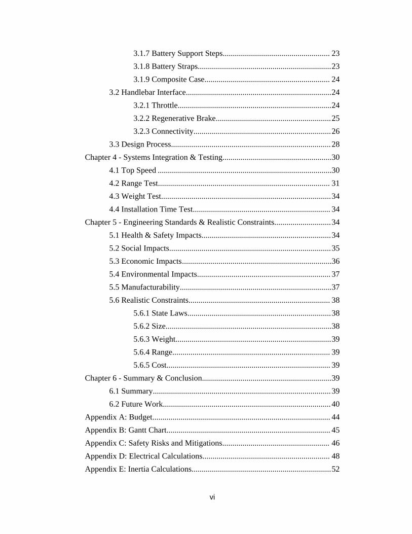
3.1.7 Battery Support Steps..................................................... 23
3.1.8 Battery Straps.................................................................. 23
3.1.9 Composite Case.............................................................. 24
3.2 Handlebar Interface........................................................................ 24
3.2.1 Throttle............................................................................ 24
3.2.2 Regenerative Brake......................................................... 25
3.2.3 Connectivity.................................................................... 26
3.3 Design Process............................................................................... 28
Chapter 4 - Systems Integration & Testing......................................................30
4.1 Top Speed ......................................................................................30
4.2 Range Test..................................................................................... 31
4.3 Weight Test.................................................................................... 34
4.4 Installation Time Test.................................................................... 34
Chapter 5 - Engineering Standards & Realistic Constraints............................ 34
5.1 Health & Safety Impacts................................................................ 34
5.2 Social Impacts................................................................................ 35
5.3 Economic Impacts ..........................................................................36
5.4 Environmental Impacts.................................................................. 37
5.5 Manufacturability........................................................................... 37
5.6 Realistic Constraints...................................................................... 38
5.6.1 State Laws....................................................................... 38
5.6.2 Size.................................................................................. 38
5.6.3 Weight............................................................................. 39
5.6.4 Range.............................................................................. 39
5.6.5 Cost................................................................................. 39
Chapter 6 - Summary & Conclusion................................................................ 39
6.1 Summary........................................................................................ 39
6.2 Future Work................................................................................... 40
Appendix A: Budget........................................................................................ 44
Appendix B: Gantt Chart................................................................................. 45
Appendix C: Safety Risks and Mitigations..................................................... 46 Appendix D: Electrical Calculations............................................................... 48
Appendix E: Inertia Calculations..................................................................... 52

vii
Appendix F: Finite Element Analysis.............................................................. 53
Appendix G: Wind Speed to Pressure Conversion Chart................................ 58
Appendix H: Business Plan............................................................................. 59
Appendix I: Artistic Contributions.................................................................. 65
Appendix J: Mechanical Drawings.................................................................. 66
viii
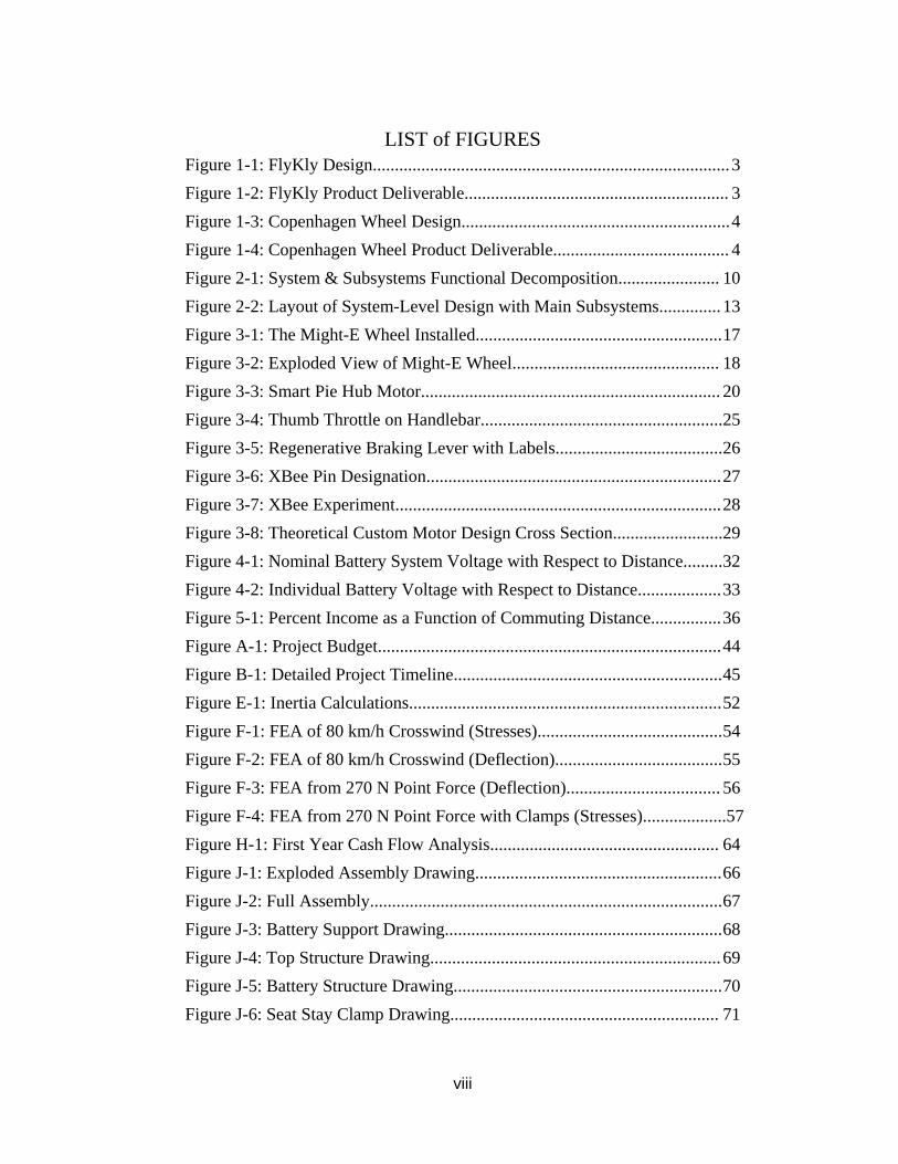
LIST of FIGURES
Figure 1-1: FlyKly Design................................................................................. 3
Figure 1-2: FlyKly Product Deliverable............................................................ 3
Figure 1-3: Copenhagen Wheel Design............................................................. 4
Figure 1-4: Copenhagen Wheel Product Deliverable........................................ 4
Figure 2-1: System & Subsystems Functional Decomposition....................... 10
Figure 2-2: Layout of System-Level Design with Main Subsystems.............. 13
Figure 3-1: The Might-E Wheel Installed........................................................ 17
Figure 3-2: Exploded View of Might-E Wheel............................................... 18
Figure 3-3: Smart Pie Hub Motor.................................................................... 20
Figure 3-4: Thumb Throttle on Handlebar....................................................... 25
Figure 3-5: Regenerative Braking Lever with Labels...................................... 26
Figure 3-6: XBee Pin Designation................................................................... 27
Figure 3-7: XBee Experiment.......................................................................... 28
Figure 3-8: Theoretical Custom Motor Design Cross Section.........................29
Figure 4-1: Nominal Battery System Voltage with Respect to Distance......... 32
Figure 4-2: Individual Battery Voltage with Respect to Distance................... 33
Figure 5-1: Percent Income as a Function of Commuting Distance................ 36
Figure A-1: Project Budget.............................................................................. 44
Figure B-1: Detailed Project Timeline............................................................. 45
Figure E-1: Inertia Calculations....................................................................... 52
Figure F-1: FEA of 80 km/h Crosswind (Stresses).......................................... 54
Figure F-2: FEA of 80 km/h Crosswind (Deflection)...................................... 55
Figure F-3: FEA from 270 N Point Force (Deflection)................................... 56
Figure F-4: FEA from 270 N Point Force with Clamps (Stresses)...................57
Figure H-1: First Year Cash Flow Analysis.................................................... 64
Figure J-1: Exploded Assembly Drawing........................................................ 66
Figure J-2: Full Assembly................................................................................ 67
Figure J-3: Battery Support Drawing............................................................... 68
Figure J-4: Top Structure Drawing.................................................................. 69
Figure J-5: Battery Structure Drawing............................................................. 70
Figure J-6: Seat Stay Clamp Drawing............................................................. 71
ix
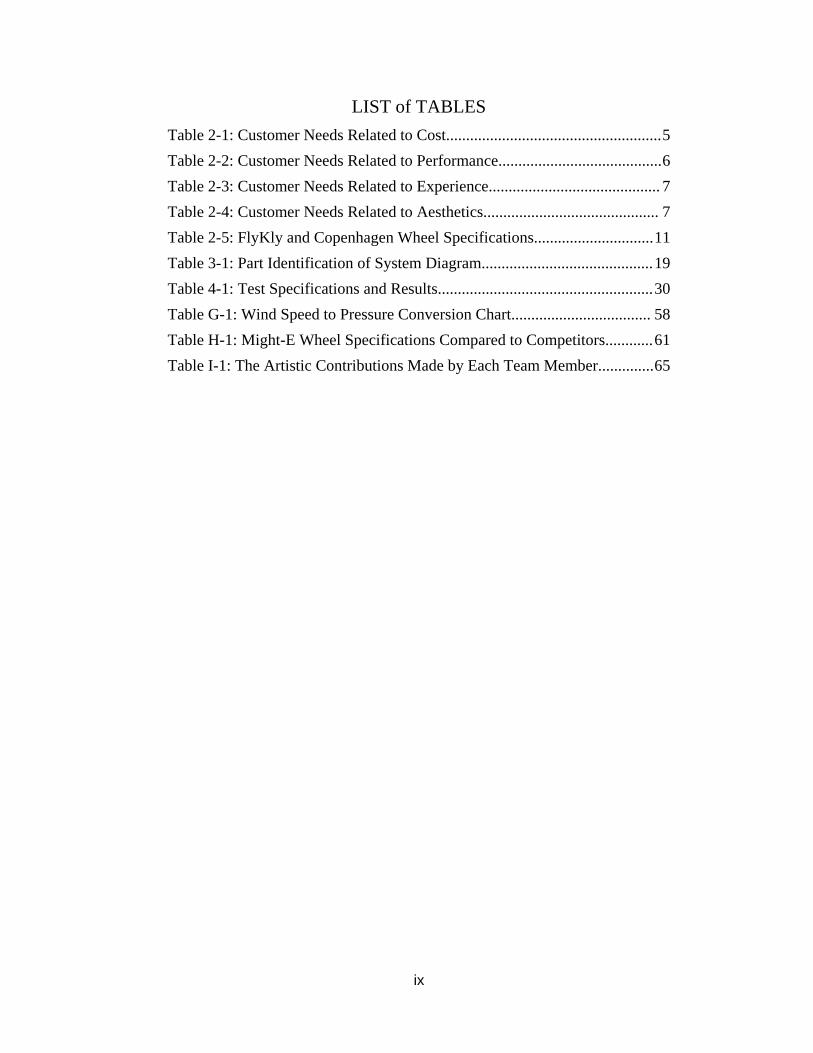
LIST of TABLES
Table 2-1: Customer Needs Related to Cost...................................................... 5
Table 2-2: Customer Needs Related to Performance......................................... 6
Table 2-3: Customer Needs Related to Experience........................................... 7
Table 2-4: Customer Needs Related to Aesthetics............................................ 7
Table 2-5: FlyKly and Copenhagen Wheel Specifications.............................. 11
Table 3-1: Part Identification of System Diagram........................................... 19
Table 4-1: Test Specifications and Results...................................................... 30
Table G-1: Wind Speed to Pressure Conversion Chart................................... 58
Table H-1: Might-E Wheel Specifications Compared to Competitors............ 61
Table I-1: The Artistic Contributions Made by Each Team Member.............. 65
1
1. INTRODUCTION
1.1 Problem Statement
Electric bikes are proving to be an increasingly reliable source of transportation, but with
large price tags and existing conversion kits proving too complicated and unapproachable for
the average user, commuters are failing to consider electric bicycles as an option. Might-E
Wheel seeks to provide the most intuitive and user-friendly bicycle conversion kit with its
easy-to-install design.
1.2 Project Objectives
The Might-E Wheel is an innovation for the urban commuter, the recreational user, and
anyone who wishes to make his travel more sustainable. The wheel provides an alternative to
conventional, inefficient modes of transportation and reduces the carbon footprint of the
everyday commuter. Our design will convert an existing bicycle into an electric bike
controlled by a thumb throttle. The conversion is easily done by installing the Might-E
Wheel to the rear of the bicycle and mounting the included handlebar assembly, which
includes a remote controlled throttle and a regenerative braking lever. The motor, batteries,
and additional electrical components will be stored within the wheel assembly. Making the
motor, batteries, and controls a single assembly will make the design more approachable for
average users to convert his or her bike. The ease of installation will allow for both novice
and expert users to embrace our innovation in alternative transportation technology. The
wheel is different and innovative because it allows the freedom of selecting assistive
pedaling or full-power electric, while containing all of the necessary components enclosed
and protected safely within the wheel or surrounding structure. The rider’s experience is
enhanced by the ability to choose if he or she wants to coast freely on full electric power or
pedal it his/herself, like a traditional bike. The electric capabilities of this bicycle wheel
enhances the riding experience by allowing riders to throttle through difficult parts of their
ride, making a commute by bicycle more appealing and accessible.
The project utilizes an approach of “upcycling” with regard to innovation. Instead of
creating an entirely new bicycle with the intent of replacing the former product, we have
2
designed a product that enhances the user’s current product while minimizing waste and cost.
Our easily installable upgrade cuts down on emissions today while addressing the problem of
future waste management. We believe this simple, relatively inexpensive product will help
take cars off the road and improve riders’ quality of life by allowing them to spend more time
outdoors and less time in traffic.
1.3 Project Background and Motivation
Commutes in the San Francisco Bay Area are known to be some of the worst in the country
with regards to traffic and pollution. The problem can be analyzed both on individual and
collective levels. In a study published by the San Francisco Chronicle, it was estimated that
the average commuter wastes 25 gallons of excess fuel per year due to congestion and has a
“yearly congestion cost” of $1,266 [1] in addition to regular travel/commuting costs. If our
product is sold at the target price ($1,100), then savings during high-traffic periods alone
over a few years may be enough to convince commuters to convert.
Looking at Bay Area traffic on a larger scale adds scope and motivation to our project. The
same study stated that Bay Area commuters as a whole spend 155 million hours in traffic and
“excess fuel consumption and truck delays” cost an overall $3.3 billion annually [1]. The
hope is that many individuals would use our product to not only reduce these numbers, but
also to have an impact on the pollution from the excess traffic that affects both the
environment and residents living in metropolitan areas. Our success would result in fewer
vehicles on the road, leading to less pollution and a drop in wasted time in traffic. More on
the environmental, social, health, and economic impacts of automobiles and bicycles can be
found in Chapter 5.
Electric bicycles also serve as a recreational product. Tim Neville wrote in The New York
Times about his journey over the Alps on an electric bicycle, and the many others he met on
his trip also travelling by electric bicycle [2]. Neville, like many other cyclists, enjoys riding
to explore new scenic areas. He explains that electric bikes have extended the possibility of
traveling long distances on a bike to people who may not have the endurance or physical
3
capability. This is particularly useful to older cyclists who begin to experience pain due to
Arthritis and other factors related to age.
Existing electric bicycles and conversion kits are unappealing to consumers in a number of
ways. Electric bicycles are expensive, with low-end models costing around $1,500 to $3,000
and prices exceeding $10,000 for the luxury models. Current conversion kits are
complicated, cluttered, and unappealing to the novice user. At a minimum these kits require
the user to install the new wheel, batteries and some mounting system, handlebar controls.
The wiring runs along the length of the bike from the handlebars to the wheel, making the
bike appear cluttered. Many of the current electric bike conversion kits also require the user
to program the control system. These systems are complicated and many come without
adequate documentation on how to install.
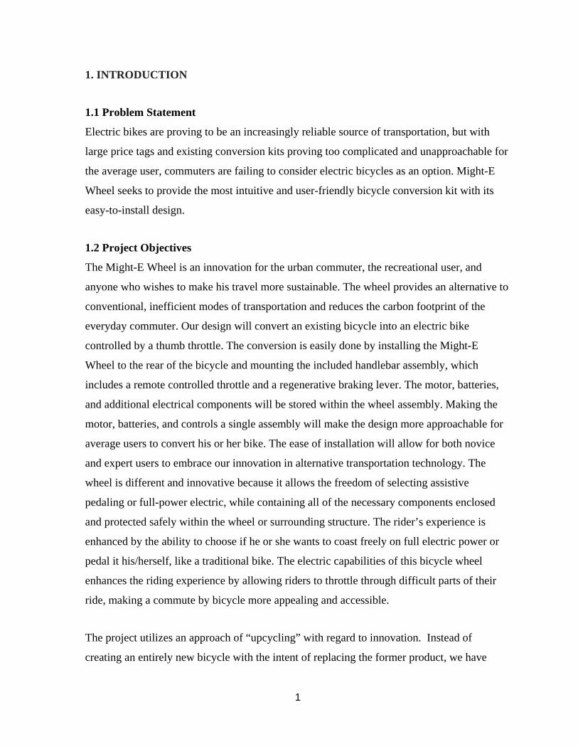
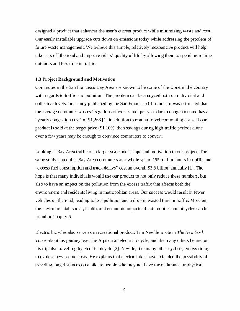
Currently, only two other in-wheel conversion kits exist: FlyKly Smart Wheel (Figures 1-1 &
1-2) and the Copenhagen Wheel (Figures 1-3 & 1-4). Note that all figures taken from
external sources were reproduced with permission of their copyright holders.
Figure 1-1: FlyKly Design [3]
Figure 1-2: FlyKly Product Deliverable [3]
4
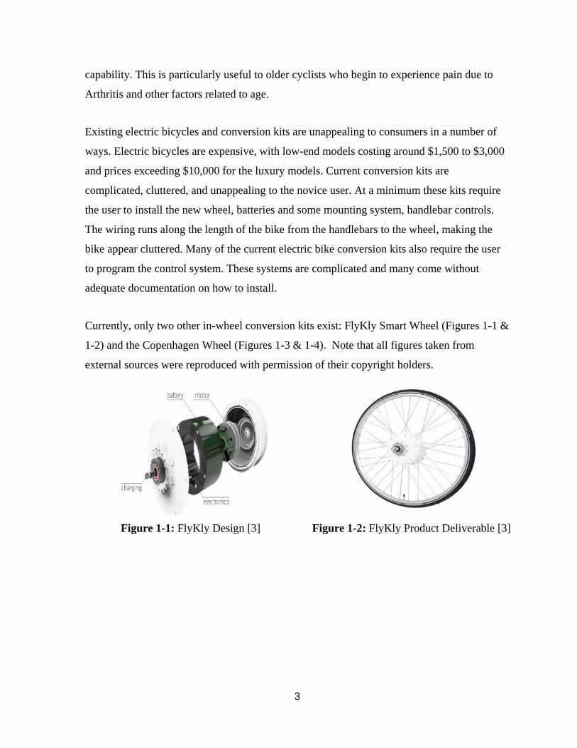
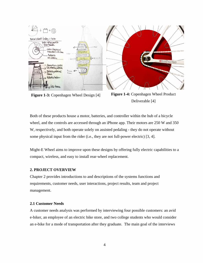
Figure 1-3: Copenhagen Wheel Design [4]
Figure 1-4: Copenhagen Wheel Product
Deliverable [4]
Both of these products house a motor, batteries, and controller within the hub of a bicycle
wheel, and the controls are accessed through an iPhone app. Their motors are 250 W and 350
W, respectively, and both operate solely on assisted pedaling - they do not operate without
some physical input from the rider (i.e., they are not full-power electric) [3, 4].
Might-E Wheel aims to improve upon these designs by offering fully electric capabilities to a
compact, wireless, and easy to install rear-wheel replacement.
2. PROJECT OVERVIEW
Chapter 2 provides introductions to and descriptions of the systems functions and
requirements, customer needs, user interactions, project results, team and project
management.
2.1 Customer Needs
A customer needs analysis was performed by interviewing four possible customers: an avid
e-biker, an employee of an electric bike store, and two college students who would consider
an e-bike for a mode of transportation after they graduate. The main goal of the interviews
5
was to find the motivation for purchase and use of e-bikes and to form needs/requirements
from the observations.
The reasons for purchasing an e-bike varied and applied to a wide demographic. The store
employee provided the majority of the customer information, although the avid e-biker shed
light on some valuable personal experience. It was found that people are willing to commute
farther by e-bike than by standard bike due to less stress on the user; therefore, people in
metropolitan areas are likely customers. Some purchased e-bikes for commutes, while others
purchased for adventure. The e-bikes make climbing hills and mountains easier, which
makes lengthy trips a more viable option. Others cannot drive due to complications in their
lives (such as DUI’s or losing their driver’s license). It was found that people who cannot
have a driver’s license are not interested in the exercise that traditional bikes offer.
Therefore, they are willing to use e-bikes because they are not strenuous and do not require a
license. The final (and biggest) motivation was found to be enjoyment. The fun had while
riding an e-bike is a unique and joyful experience, according to the avid e-biker. This aspect
opens up a large market for those who want to use e-bikes as a recreational tool.
Next, customer needs/requirements were formed from the observations in the interviews. It
was decided to divide the needs into four categories: cost, performance, experience, and
aesthetics. Each one contributes to the overall appeal of the product, but they were analyzed
separately in order to isolate and concentrate on each specific area of the design. An
observation → problem → need approach was then taken to identify what the customer needs
from the product; this approach involves stating an observation from the
interviews/experiences, identifying a problem from the observation, and deriving a need from
the problem.
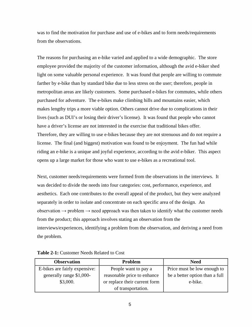
Table 2-1: Customer Needs Related to Cost
Observation Problem Need E-bikes are fairly expensive:
generally range $1,000-$3,000.
People want to pay a reasonable price to enhance or replace their current form
of transportation.
Price must be low enough to be a better option than a full
e-bike.
6
The cost category is straightforward, yet remains the most important constraint for the
product. Participants said they would be interested in a conversion for their existing bike, but
cost would be an important factor in purchasing. If the product is effective, but costs the
same as a full e-bike, then participants said they would rather buy the e-bike in full.
Therefore, the product cost must be low enough so that it draws customers away from the
fully assembled vehicles.
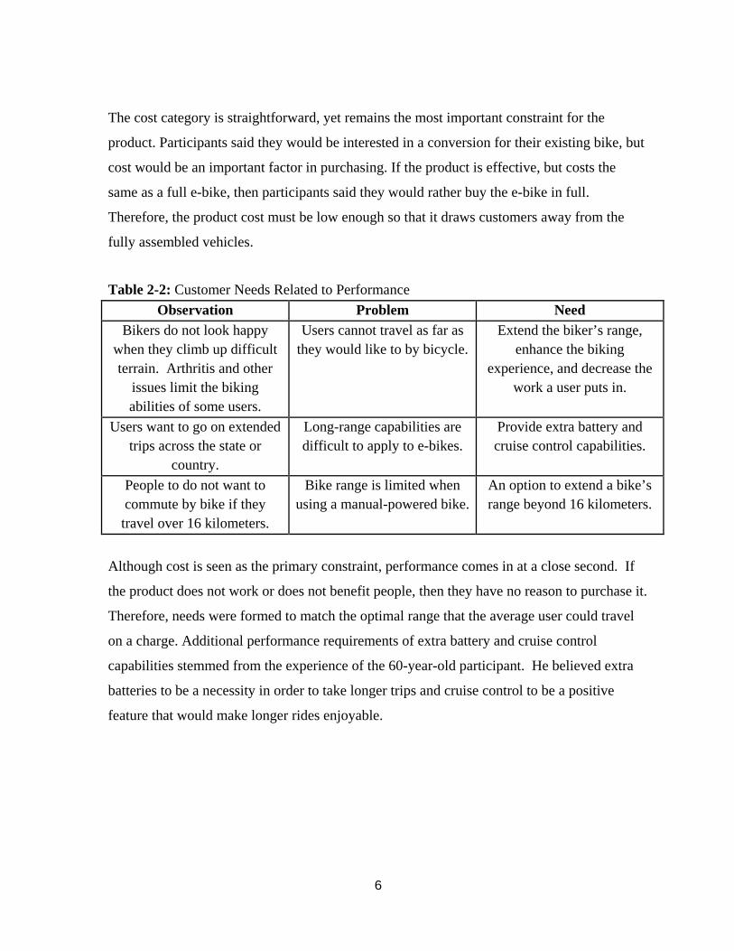
Table 2-2: Customer Needs Related to Performance Observation Problem Need
Bikers do not look happy when they climb up difficult terrain. Arthritis and other
issues limit the biking abilities of some users.
Users cannot travel as far as they would like to by bicycle.
Extend the biker’s range, enhance the biking
experience, and decrease the work a user puts in.
Users want to go on extended trips across the state or
country.
Long-range capabilities are difficult to apply to e-bikes.
Provide extra battery and cruise control capabilities.
People to do not want to commute by bike if they travel over 16 kilometers.
Bike range is limited when using a manual-powered bike.
An option to extend a bike’s range beyond 16 kilometers.
Although cost is seen as the primary constraint, performance comes in at a close second. If
the product does not work or does not benefit people, then they have no reason to purchase it.
Therefore, needs were formed to match the optimal range that the average user could travel
on a charge. Additional performance requirements of extra battery and cruise control
capabilities stemmed from the experience of the 60-year-old participant. He believed extra
batteries to be a necessity in order to take longer trips and cruise control to be a positive
feature that would make longer rides enjoyable.
7
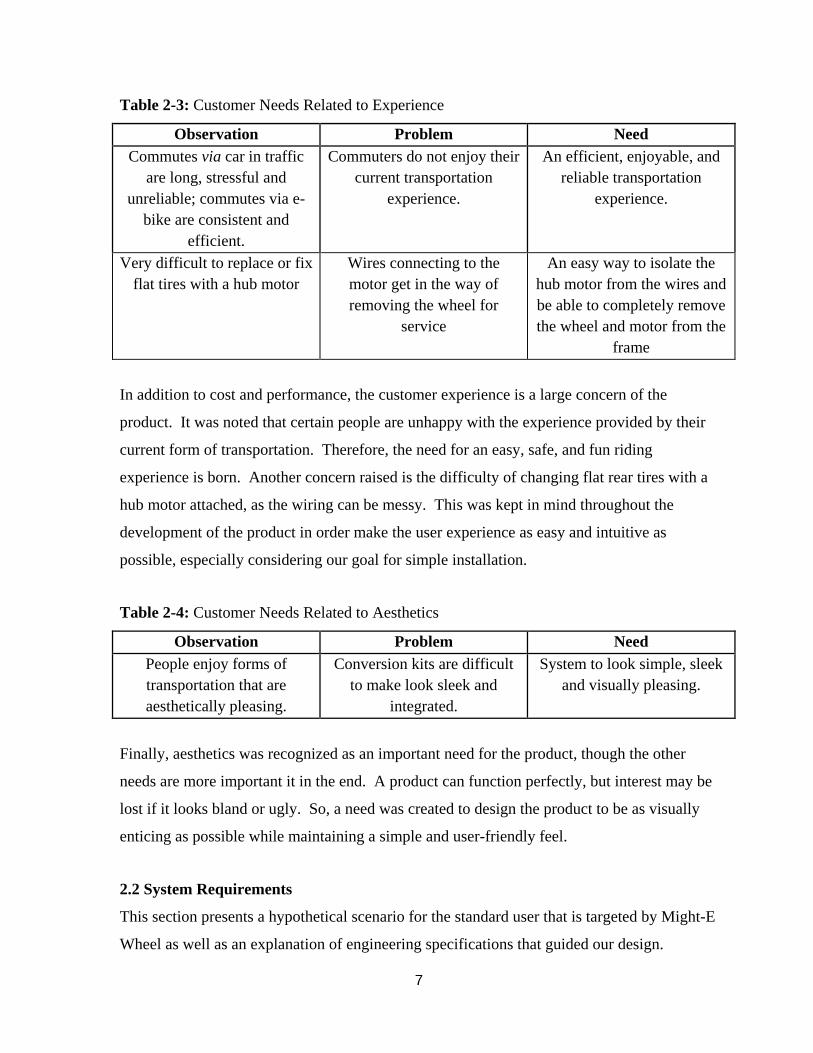
Table 2-3: Customer Needs Related to Experience
Observation Problem Need Commutes via car in traffic
are long, stressful and unreliable; commutes via e-
bike are consistent and efficient.
Commuters do not enjoy their current transportation
experience.
An efficient, enjoyable, and reliable transportation
experience.
Very difficult to replace or fix flat tires with a hub motor
Wires connecting to the motor get in the way of removing the wheel for
service
An easy way to isolate the hub motor from the wires and be able to completely remove the wheel and motor from the
frame
In addition to cost and performance, the customer experience is a large concern of the
product. It was noted that certain people are unhappy with the experience provided by their
current form of transportation. Therefore, the need for an easy, safe, and fun riding
experience is born. Another concern raised is the difficulty of changing flat rear tires with a
hub motor attached, as the wiring can be messy. This was kept in mind throughout the
development of the product in order make the user experience as easy and intuitive as
possible, especially considering our goal for simple installation.
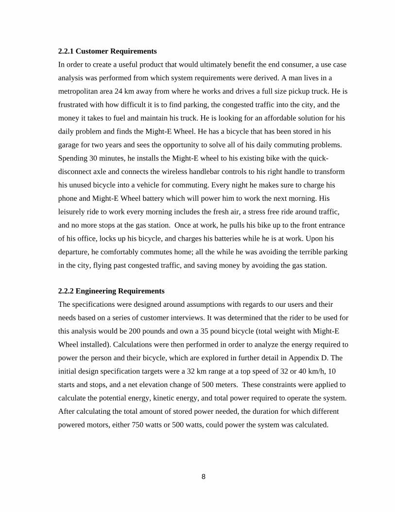
Table 2-4: Customer Needs Related to Aesthetics
Observation Problem Need People enjoy forms of transportation that are aesthetically pleasing.
Conversion kits are difficult to make look sleek and
integrated.
System to look simple, sleek and visually pleasing.
Finally, aesthetics was recognized as an important need for the product, though the other
needs are more important it in the end. A product can function perfectly, but interest may be
lost if it looks bland or ugly. So, a need was created to design the product to be as visually
enticing as possible while maintaining a simple and user-friendly feel.
2.2 System Requirements
This section presents a hypothetical scenario for the standard user that is targeted by Might-E
Wheel as well as an explanation of engineering specifications that guided our design.
8
2.2.1 Customer Requirements
In order to create a useful product that would ultimately benefit the end consumer, a use case
analysis was performed from which system requirements were derived. A man lives in a
metropolitan area 24 km away from where he works and drives a full size pickup truck. He is
frustrated with how difficult it is to find parking, the congested traffic into the city, and the
money it takes to fuel and maintain his truck. He is looking for an affordable solution for his
daily problem and finds the Might-E Wheel. He has a bicycle that has been stored in his
garage for two years and sees the opportunity to solve all of his daily commuting problems.
Spending 30 minutes, he installs the Might-E wheel to his existing bike with the quick-
disconnect axle and connects the wireless handlebar controls to his right handle to transform
his unused bicycle into a vehicle for commuting. Every night he makes sure to charge his
phone and Might-E Wheel battery which will power him to work the next morning. His
leisurely ride to work every morning includes the fresh air, a stress free ride around traffic,
and no more stops at the gas station. Once at work, he pulls his bike up to the front entrance
of his office, locks up his bicycle, and charges his batteries while he is at work. Upon his
departure, he comfortably commutes home; all the while he was avoiding the terrible parking
in the city, flying past congested traffic, and saving money by avoiding the gas station.
2.2.2 Engineering Requirements
The specifications were designed around assumptions with regards to our users and their
needs based on a series of customer interviews. It was determined that the rider to be used for
this analysis would be 200 pounds and own a 35 pound bicycle (total weight with Might-E
Wheel installed). Calculations were then performed in order to analyze the energy required to
power the person and their bicycle, which are explored in further detail in Appendix D. The
initial design specification targets were a 32 km range at a top speed of 32 or 40 km/h, 10
starts and stops, and a net elevation change of 500 meters. These constraints were applied to
calculate the potential energy, kinetic energy, and total power required to operate the system.
After calculating the total amount of stored power needed, the duration for which different
powered motors, either 750 watts or 500 watts, could power the system was calculated.
9
Additional features included in the original design specifications, such as assisted pedaling
and regenerative braking, were also explored through calculations to determine exactly how
beneficial each additional feature would be, these calculations can also be found in Appendix
D. The extended range of assisted pedaling was calculated by determining the power a
human could generate and summing it to the power already being supplied to the system. The
utility of regenerative braking at different speeds was also analyzed in order to determine its
efficacy. Though some of the specifications were later changed or adapted as the project
progressed, these initial calculations played an integral role in how the project was
understood and the designs that followed.
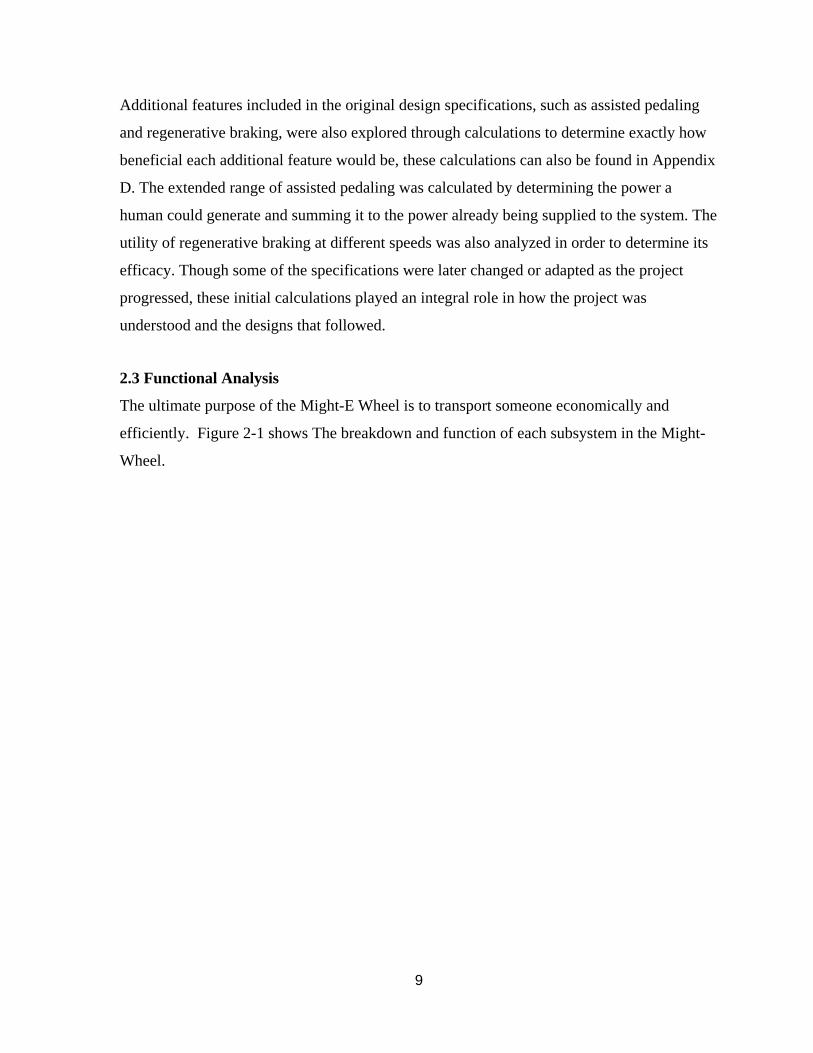
2.3 Functional Analysis
The ultimate purpose of the Might-E Wheel is to transport someone economically and
efficiently. Figure 2-1 shows The breakdown and function of each subsystem in the Might-
Wheel.
10
Figure 2-1: Functional Decomposition of System and Subsystems
2.4 Benchmarking Results
Only two products currently exist that are immediately comparable with Might-E Wheel:
FlyKly and Copenhagen Wheel (See Figures 1-1 through 1-4). Other electric conversion kits
exist, but they require the separate purchase of batteries which must be externally mounted to
the bike frame. Might-E Wheel, along with FlyKly and Copenhagen Wheel, provides the
batteries as part of the system for ease of purchase and user-friendly installation and
operation.
11
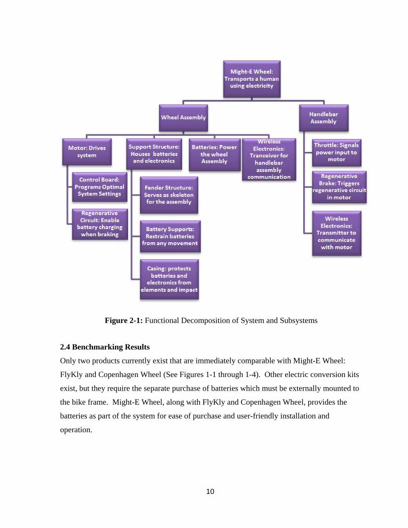
Table 2-5: The Important Specifications of Might-E Wheel’s Competitors
While Might-E Wheel sets out to solve the same problems as these competitors, there are a
few major system differences worth emphasizing. First, they both run using pedal assist
systems only, whereas Might-E Wheel uses a throttle to deliver its power. Their pedal assist
systems increase their range specifications, as human power is also inherently used in those
tests. For example, if the wheel is set to amplify the rider’s power by 2 times their input and
the rider puts in 100 W, the motor will put in 100 W. The other main difference is that both
competitors use a mobile app interface, which requires the user to own a smartphone and
mount it to the handlebars; Might-E Wheel wanted to avoid this type of interface and user
requirement, reinforcing the decision to use a full-power electric throttle. A smartphone
interface would be unreliable if the rider’s phone battery died. Also, by eliminating the need
for a compatible smartphone when using Might-E Wheel, we are able to equip even more
people with sustainable transportation.
2.5 System Level Issues, Options, Tradeoffs, and Rationales
Issues typically arise in the design process that forces the designers to make decisions that
involve tradeoffs. There are numerous shapes that the system can take, each with its own
advantages and disadvantages. Some issues/options that the Might-E Wheel faced included
the size and weight, optimizing the range, the wires and electrical connections, and the
approachability vs. the functionality.
The first significant tradeoff the team faced was whether or not to enclose the entire system
within the hub of the wheel. Doing this would allow for simpler wheel installation, but
12
would limit the space available for the batteries and electronics running the system. Instead,
the team opted for a fender design that mounted on the external axle of the hub but was still
no wider than the rear fork of the bike. This allowed for efficient mounting of the proper
amount of batteries and electronics.
The bigger the wheel is, the bigger and more powerful the motor can be. However, more
batteries would be needed to power a bigger motor for the same range, adding to the overall
weight of the product. This would make the user’s bike heavier and more difficult to
transport. Therefore, the decision was made to use a motor rated at 200 to 400 W in order to
efficiently power the wheel without needing a large number of batteries.
Range was also given consideration in the design. If the wheel has a good stream of power
but cannot transport the user on a short or medium commute, then it is useless. Extended
range incorporates more batteries, which again adds to the overall weight. Four Li-ion
battery packs were chosen to power the system. Each pack is rated at 11.1 V and 10.2 Ah
(113 Wh). The four battery packs weighed around 2 kg in total, a small addition to the
system that would not weigh slow the rider too much.
A large issue facing the Might-E Wheel was that of electrical connections. A throttle is
desired to be connected to the wheel, but simplicity of installation must be maintained.
Attaching a wire to a rotating hub can cause many problems. Other conversion kits solve this
problem by connecting to a user’s smartphone, but the Might-E Wheel team saw this as an
unnecessary, complicated, and dangerous feature. Therefore, it was decided to use a wireless
connection between the throttle and motor for optimized safety and ease of installation and
use.
The final trade off related to functionality vs. approachability. The wheel could be made into
the most functional conversion kit on the market, but it would involve very complex
installation and user choices, in addition to a bulkier design. The Might-E Wheel aims to
make the user experience - from installation to use - as easy and pleasant as possible.
13
Therefore, functionality on the extreme end (1000 W motor or external batteries) was
sacrificed to improve the overall experience of the product.
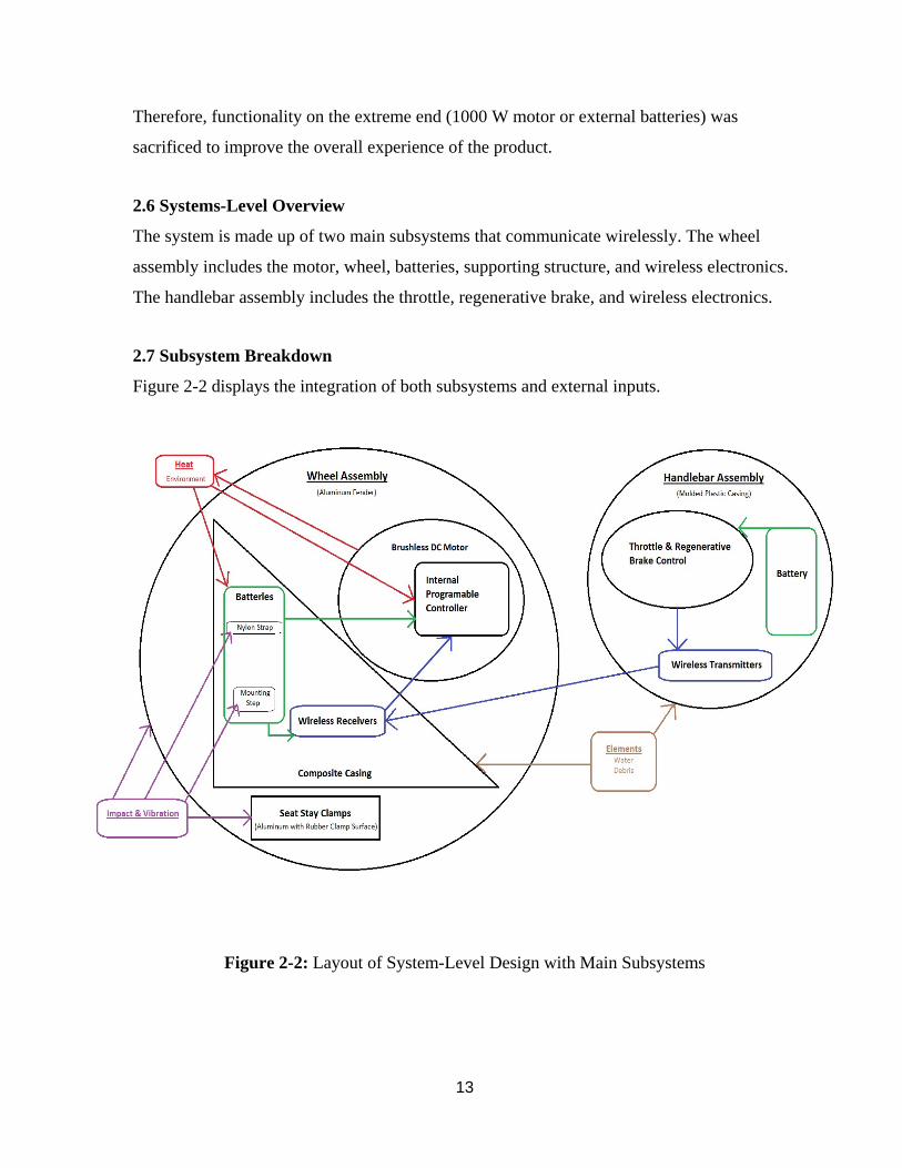
2.6 Systems-Level Overview
The system is made up of two main subsystems that communicate wirelessly. The wheel
assembly includes the motor, wheel, batteries, supporting structure, and wireless electronics.
The handlebar assembly includes the throttle, regenerative brake, and wireless electronics.
2.7 Subsystem Breakdown
Figure 2-2 displays the integration of both subsystems and external inputs.
Figure 2-2: Layout of System-Level Design with Main Subsystems
14
2.7.1 Wheel Assembly
The wheel assembly is centered around a brushless DC electric hub motor spoked in a 26”
bicycle rim. An aluminum fender mounts onto both sides of the axle and goes over top of the
wheel. This fender includes aluminum steps and nylon straps that restrain the four battery
packs used to power the motor. Two wireless receivers are also mounted, serving to facilitate
the connection to the handlebar assembly. Finally, two composite cases provide a physical
defense for the batteries and electronics from both the weather and contact with any external
object.
2.7.2 Handlebar Assembly
The handlebar assembly consists of a thumb throttle and a regenerative braking lever, both of
which were designed for our specific motor. Each component is powered separately by two
AA batteries and is connected to a wireless transmitter in order to communicate with the
wheel assembly.
2.8 Team and Project Management
Managing a project of this scale was a job within itself and was made up of many different
components. The following section details these components and the team’s project
management approach.
2.8.1 Challenges & Constraints
Lack of experience and expertise in the field led to challenges in the design process. Multiple
iterations of certain parts of the design and fabrication processes were required because not
every interaction was understood at the time. This led to a bit of delay in the full fabrication
and testing of the product.
2.8.2 Budget
The budget was based on necessary parts and restrictions based on funding received to date.
Might-E Wheel received a total of $2,500, with $500 from the Roelandts Grant and $2,000
from the SCU School of Engineering. The discrete budget can be found in Appendix A. The

15
majority of the budget was allocated for specific parts, but money was also used for testing
materials and repairing the bike used in the project.
2.8.3 Timeline
The timeline is laid out in the Gantt chart in Appendix B. The project began at the end of
September with initial research into existing products and what needed to be improved upon.
Grant proposals were also submitted early in the process (October) and continued to mid-
November, terminating with a venture capitalist pitch. An analysis of customer needs began
in November. A range of potential customer, from current electric bicycle users to people
with little to no knowledge of electric bicycles were interviewed to gain an understanding of
their interest in a product of this type and what they would expect from it. From these needs,
features, and requirements a design was developed. With identified features, a more detailed
budget was formed.
The system requirements were analyzed to determine the motor and battery sizes needed.
With this in mind, the team was able to begin the design process. The design process began
in January with initial system design concepts and a mockup to represent the general concept.
The design process for all subsystems lasted through March, when parts were ordered.
Fabrication took place through March and April. May was for testing and presenting the
project at the Santa Clara University Senior Design Conference
2.8.4 Risks and Mitigations
In the final assembly of the design, several risks were faced in possible failure of parts or in
the system not working properly when assembled. System risks included calibration of the
regenerative brake and throttle for full power electric. Wire management and battery safety
also presented risks, along with the natural safety risks of machining the parts used in the
product. These risks were thought of ahead of time, and careful precautions were taken to
mitigate many of them. The full list of safety risks and mitigations can be found in Appendix
C.
16
The one risk that was not fully mitigated was the shorting of the batteries. Their mounting
steps rubbed off the protective casing on one of the battery backs; this caused two of the
packs to short circuit together with the support structure. They exploded and were thereafter
unusable. No one or anything else was harmed, but this malfunction did prevent the team
from completing one of its tests. This risk could have been mitigated by not mounting the
battery packs directly on metal, and instead using some sort of insulating material between
the two.
2.8.5 Team Management
The team divided up the work as equally as possible for the project and held each other
accountable for due dates. The mechanical engineers were all responsible for the design of
the system. Once the design had been completed, the team worked on the production of the
mechanical and electrical systems in parallel for increased efficiency. Two of the mechanical
engineers (Daniel Doke and Zach Jesberger) were responsible for the machining of parts and
assembly of the system. The other mechanical engineer and the electrical engineer (Abby
Grills and Jared O’Rourke, respectively) were responsible for the battery, motor, and
wireless testing. These two divergent teams paralleled each other and converged at the end
of the fabrication process.
The only large issue faced in the team management was the coordination between the
schedules of the four team members and two advisors. It was very difficult to find times
when everyone was free and certain members had to make sacrifices at some points.
Overall, it was a positive and fruitful team dynamic and experience.
3. SUBSYSTEM DESCRIPTIONS
The main subsystems consist of the wheel assembly and the handlebar assembly. This
chapter analyzes the functions and components of each subsystem.
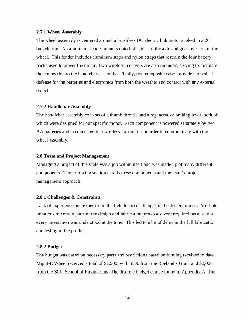
3.1 Rear Wheel Assembly
The final design consists of a fender like structure that mounts on both sides of the axle and
goes over the top of the wheel, as well as the wheel itself. This design was ultimately chosen
17
because it provided more space to store batteries and other components, resulting in a longer
range and more powerful wheel. Figure 3-1 shows the final design built and assembled onto
the bike.
Figure 3-1: Might-E Wheel Assembled to the Bike
The rear wheel acts as a vessel to bring together all of the necessary components needed to
propel the bicycle. By having all of the needed parts packaged within the seat stays, this aids
in the ease of installation and betters the user’s experience with the product. It acts as a
space to house the motor, batteries, and wireless electronics and is concealed by a protective
cover.
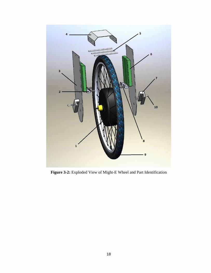
Figure 3-2 shows an exploded view of the rear wheel assembly with all of the major parts
and components labeled, and Table 3-1 describes the part corresponding to each number
label.
18
Figure 3-2: Exploded View of Might-E Wheel and Part Identification
19
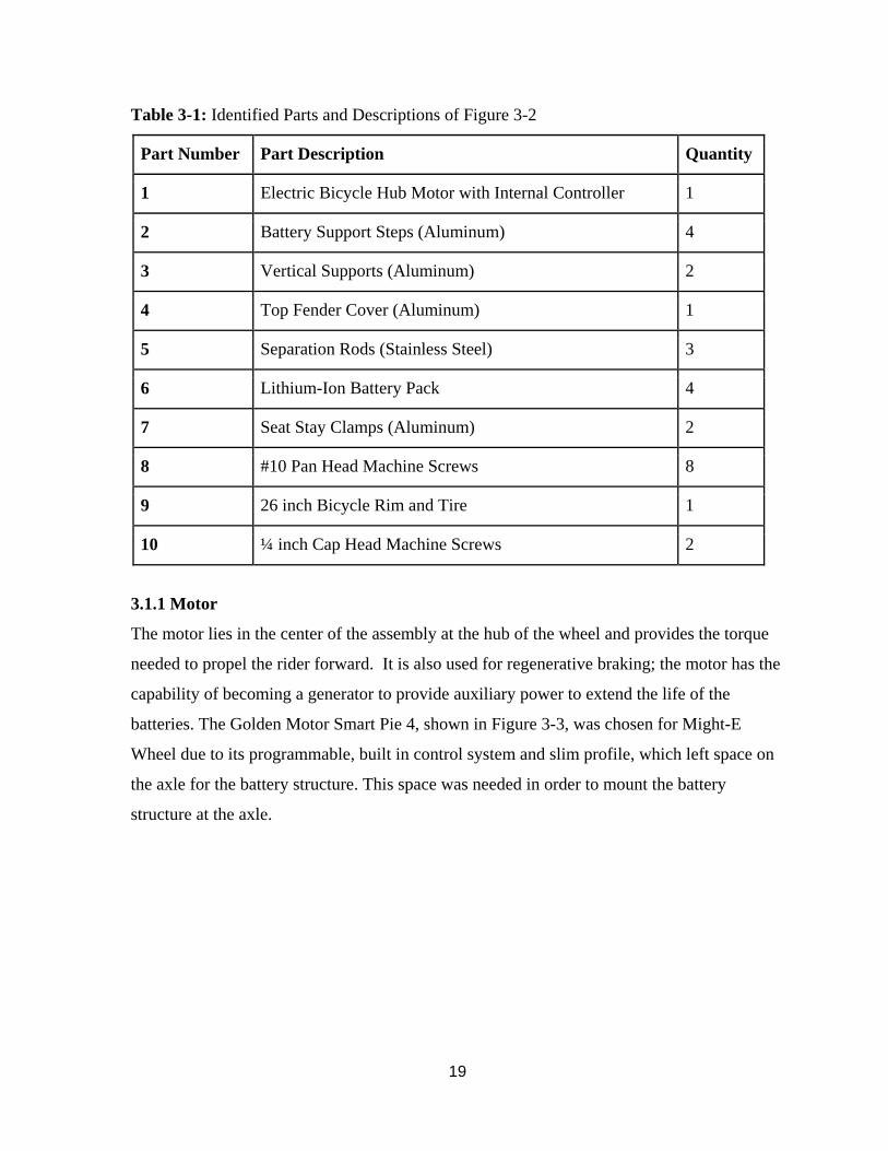
Table 3-1: Identified Parts and Descriptions of Figure 3-2
Part Number Part Description Quantity
1 Electric Bicycle Hub Motor with Internal Controller 1
2 Battery Support Steps (Aluminum) 4
3 Vertical Supports (Aluminum) 2
4 Top Fender Cover (Aluminum) 1
5 Separation Rods (Stainless Steel) 3
6 Lithium-Ion Battery Pack 4
7 Seat Stay Clamps (Aluminum) 2
8 #10 Pan Head Machine Screws 8
9 26 inch Bicycle Rim and Tire 1
10 ¼ inch Cap Head Machine Screws 2
3.1.1 Motor
The motor lies in the center of the assembly at the hub of the wheel and provides the torque
needed to propel the rider forward. It is also used for regenerative braking; the motor has the
capability of becoming a generator to provide auxiliary power to extend the life of the
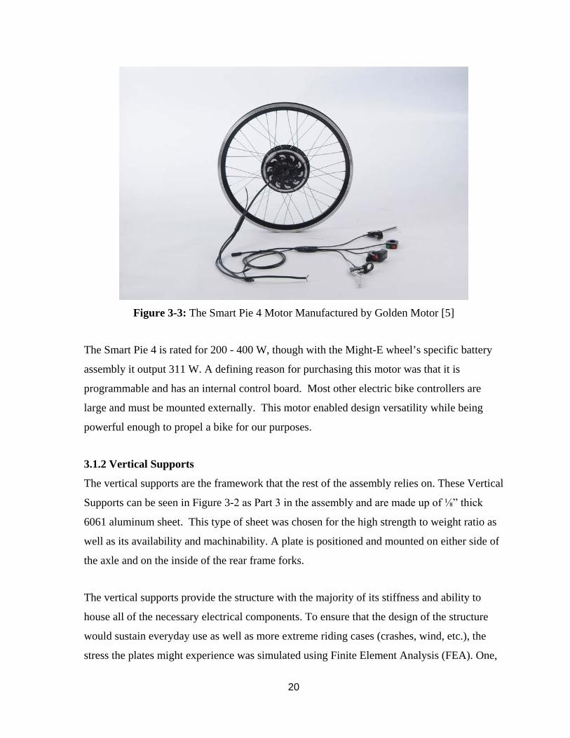
batteries. The Golden Motor Smart Pie 4, shown in Figure 3-3, was chosen for Might-E
Wheel due to its programmable, built in control system and slim profile, which left space on
the axle for the battery structure. This space was needed in order to mount the battery
structure at the axle.
20
Figure 3-3: The Smart Pie 4 Motor Manufactured by Golden Motor [5]
The Smart Pie 4 is rated for 200 - 400 W, though with the Might-E wheel’s specific battery
assembly it output 311 W. A defining reason for purchasing this motor was that it is
programmable and has an internal control board. Most other electric bike controllers are
large and must be mounted externally. This motor enabled design versatility while being
powerful enough to propel a bike for our purposes.
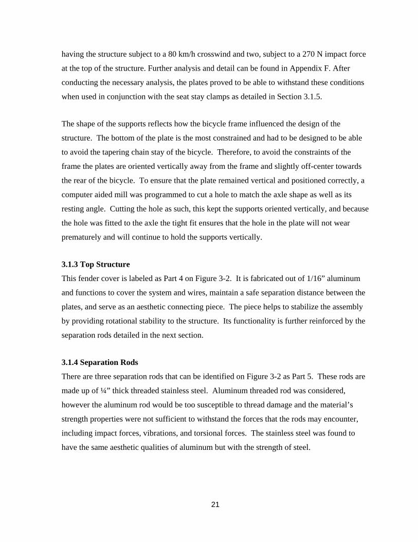
3.1.2 Vertical Supports
The vertical supports are the framework that the rest of the assembly relies on. These Vertical
Supports can be seen in Figure 3-2 as Part 3 in the assembly and are made up of ⅛” thick
6061 aluminum sheet. This type of sheet was chosen for the high strength to weight ratio as
well as its availability and machinability. A plate is positioned and mounted on either side of
the axle and on the inside of the rear frame forks.
The vertical supports provide the structure with the majority of its stiffness and ability to
house all of the necessary electrical components. To ensure that the design of the structure
would sustain everyday use as well as more extreme riding cases (crashes, wind, etc.), the
stress the plates might experience was simulated using Finite Element Analysis (FEA). One,
21
having the structure subject to a 80 km/h crosswind and two, subject to a 270 N impact force
at the top of the structure. Further analysis and detail can be found in Appendix F. After
conducting the necessary analysis, the plates proved to be able to withstand these conditions
when used in conjunction with the seat stay clamps as detailed in Section 3.1.5.
The shape of the supports reflects how the bicycle frame influenced the design of the
structure. The bottom of the plate is the most constrained and had to be designed to be able
to avoid the tapering chain stay of the bicycle. Therefore, to avoid the constraints of the
frame the plates are oriented vertically away from the frame and slightly off-center towards
the rear of the bicycle. To ensure that the plate remained vertical and positioned correctly, a
computer aided mill was programmed to cut a hole to match the axle shape as well as its
resting angle. Cutting the hole as such, this kept the supports oriented vertically, and because
the hole was fitted to the axle the tight fit ensures that the hole in the plate will not wear
prematurely and will continue to hold the supports vertically.
3.1.3 Top Structure
This fender cover is labeled as Part 4 on Figure 3-2. It is fabricated out of 1/16” aluminum
and functions to cover the system and wires, maintain a safe separation distance between the
plates, and serve as an aesthetic connecting piece. The piece helps to stabilize the assembly
by providing rotational stability to the structure. Its functionality is further reinforced by the
separation rods detailed in the next section.
3.1.4 Separation Rods
There are three separation rods that can be identified on Figure 3-2 as Part 5. These rods are
made up of ¼” thick threaded stainless steel. Aluminum threaded rod was considered,
however the aluminum rod would be too susceptible to thread damage and the material’s
strength properties were not sufficient to withstand the forces that the rods may encounter,
including impact forces, vibrations, and torsional forces. The stainless steel was found to
have the same aesthetic qualities of aluminum but with the strength of steel.
22
The rods were used for the rider’s safety and to ensure the assembly would be able to
withstand the challenges that the road may present. With the thread of the rod across the
width of the top of the assembly flanged nuts are used on the inside of the structure and
tightened to maintain a safe operational distance between the electronics on the inside face of
the vertical supports and the rotating wheel and tire running in between both vertical
supports. This is imperative to the safety of the rider for any unforeseen loading of the
structure because the rods will not allow the plates to deflect toward the rotating wheel,
which might cause mechanical failure.
These rods lastly act as a mounting structure to safely be able to run the necessary electrical
wire. The rods provide the space needed away from the rotating wheel for the wires to
securely be mounted and connected to each battery and component of the assembly.
3.1.5 Seat Stay Clamps
These clamps were designed as a result of the finite element analysis on the vertical supports
and part labeled as Part 7 on Figure 3-2. After the yielding of the vertical supports in theses
tests, it was determined that each support required an additional anchoring point to the frame
of the bike. The clamps were machined out of 6061 aluminum blocks in order to stay
lightweight but provide sufficient strength. There is one clamp for each vertical support.
Each clamp uses rubber padding to ensure a tight fight to the seat stays of the bike. The
carved out section is flush with the seat stay while the body stays flush to the vertical
support. Each clamp is anchored to the support by a ¼” cap head machine screw (Part 10 in
Figure 3-2), washers, and nylon lock nut. The cap head screw was chosen to remain low
profile and nestled within the fork. The nylon lock washers were used to prevent loosening
upon vibration of the bike and assembly.
3.1.6 Batteries
The batteries are necessary to power the motor and are located within the fender assembly.
Li-ion batteries were determined to be the best for our purposes due to their high energy
density, low self-discharge, and low maintenance needs. They are expensive batteries, but are
very reliable and are used in a wide range of applications.
23
Custom Li-ion battery packs were determined to be the ideal choice for the project. These
batteries were chosen based upon their physical size as well as their energy specifications.
Each battery package is comprised of nine separate Li-ion batteries connected and packaged
together, which can deliver 11.1 V, 10.2 Ah, and has maximum discharge rate of 14 Amps.
Each individual Li-ion battery is a High Power Panasonic Lithium 18650 rechargeable cell
that delivers 3.6 V, 3400 mAh, and has a max continuous discharge rate of 6.8 Amps each.
These cells were chosen for their high energy density, because most individual cells are rated
below 3000 mAh for the identical size cell. Keeping the volumetric space needed for the
energy storage to a minimum is important to ensure a longer range as well as to conserve
space for other components that will be needed. Based upon calculations in Appendix D, four
batteries are connected in series to create a 44.4 V battery pack rated at 10.2 Ah which is
capable of achieving about a 24 km range.
3.1.7 Battery Support Steps
Indicated in Figure 3-2 as Part 2, the individual steps can be seen underneath each battery.
Since the steps are not going to be subject to major loading conditions, they were machined
out of 6061 aluminum stock and designed to simply provide a stable mounting location for
each battery.
Each step was cut so that the battery would have a flat step to rest upon, but was also
machined to have a small lip towards the inside of the structure. This small lip helps to nest
the battery into a secure position and is fully mounted with adjustable nylon straps that are
not shown in Figure 3-2 for clarity. Further details about the straps are provided in Section
3.1.8.
3.1.8 Battery Straps
The batteries were strapped into the vertical battery supports with one inch wide nylon
adjustable straps. These straps were used to ensure that the batteries will stay in position
while the system is operating. However, these straps also simplified battery installation and
removal. The straps use low-profile clips that are easy to clasp, giving the user an option to
remove and charge the existing batteries.
24
3.1.9 Composite Case
The inside of the structure is vulnerable to weather exposure and attack from road debris.
With the batteries and electronics on the inside of the plates these items are also susceptible
to water or being damaged by flying road debris. To protect these important systems a
composite casing is used to cover all of the components on the inside of the vertical supports.
The casing is not shown in Figure 3-2 for clarity. Although these casings have not been
manufactured, their design has been completed.
The casing would be comprised of fiberglass and epoxy resin and would be molded using a
plywood mold. The fiberglass is placed within the mold and saturated with epoxy resin
being sure to dispose of extra resin. When cured, the case is cut to shape and mounting holes
are cut to attach to the vertical supports. Before installation, the case’s edge is lined with a
thin, weather tight rubber seal to protect against the elements
3.2 Handlebar Interface
The interface that the rider will be using to control the electrical components of the product
will provide the necessary functions needed, including accelerating the bicycle and
regenerative capabilities. The interface will also be connected to the rear assembly without
any physical wires.
3.2.1 Throttle
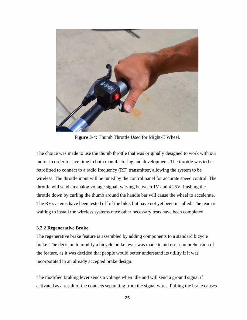
Several full-power electric bicycle throttles were tested and the thumb throttle best fit our
needs of comfort and easy installation. The throttle consists of a retrofitted electric bicycle
controller that originally was designed to be wired to the motor (see Figure 3-4).
25
Figure 3-4: Thumb Throttle Used for Might-E Wheel.
The choice was made to use the thumb throttle that was originally designed to work with our
motor in order to save time in both manufacturing and development. The throttle was to be
retrofitted to connect to a radio frequency (RF) transmitter, allowing the system to be
wireless. The throttle input will be tuned by the control panel for accurate speed control. The
throttle will send an analog voltage signal, varying between 1V and 4.25V. Pushing the
throttle down by curling the thumb around the handle bar will cause the wheel to accelerate.
The RF systems have been tested off of the bike, but have not yet been installed. The team is
waiting to install the wireless systems once other necessary tests have been completed.
3.2.2 Regenerative Brake
The regenerative brake feature is assembled by adding components to a standard bicycle
brake. The decision to modify a bicycle brake lever was made to aid user comprehension of
the feature, as it was decided that people would better understand its utility if it was
incorporated in an already accepted brake design.
The modified braking lever sends a voltage when idle and will send a ground signal if
activated as a result of the contacts separating from the signal wires. Pulling the brake causes

26
the main lever to mechanically compress the plunger pin and separate the contacts from the
signal wires, thereby eliminating the idle voltage and providing the ground signal. Figure 3-5
shows a schematic of the regenerative brake.
Figure 3-5: Regenerative Braking Lever with Labels
3.2.3 Connectivity
For easy installation, all handlebar systems must communicate with the wheel wirelessly. In
order to achieve this communication, XBee Series 1 transceivers were used. XBee Series 1
operates between 2.8V and 3.3V. The system requires four XBee Series 1 transceivers, two
as transmitters and two as receivers. The two transmitters would be mounted on the
handlebar and receive an analog signal from the regenerative brake lever and throttle. These
signals will be transmitted to their respective receivers in the wheel housing and will recreate
the signal as a digital output. In order to better recreate the signal, a digital to analog
converter will be inserted between the throttle receiver and the motor controller for a
smoother ride. The signal is discretized in order to be transmitted wirelessly, so for this
reason, it must be converted back to analog before it is sent to the motor.
The XBee Transceivers, were programmed using XCTU, a third party software. Through this
software, the XBee’s were configured, two as transmitters and two as receivers. Each pair of
27
XBee’s, consisting of one transmitter and one receiver, was set to a unique channel so that its
respective signals would not interfere with each other.
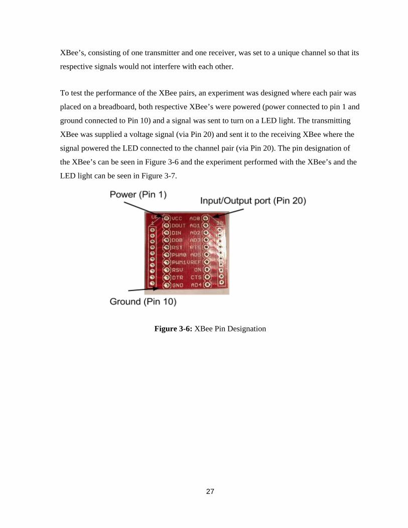
To test the performance of the XBee pairs, an experiment was designed where each pair was
placed on a breadboard, both respective XBee’s were powered (power connected to pin 1 and
ground connected to Pin 10) and a signal was sent to turn on a LED light. The transmitting
XBee was supplied a voltage signal (via Pin 20) and sent it to the receiving XBee where the
signal powered the LED connected to the channel pair (via Pin 20). The pin designation of
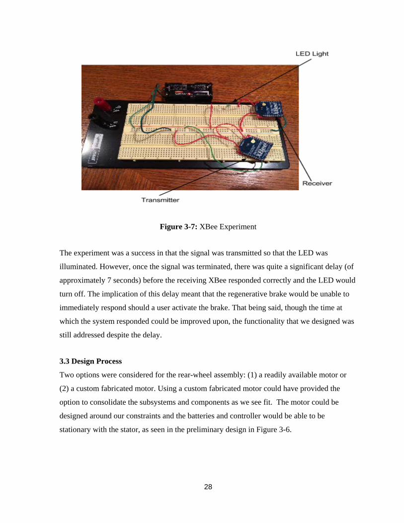
the XBee’s can be seen in Figure 3-6 and the experiment performed with the XBee’s and the
LED light can be seen in Figure 3-7.
Figure 3-6: XBee Pin Designation
28
Figure 3-7: XBee Experiment
The experiment was a success in that the signal was transmitted so that the LED was
illuminated. However, once the signal was terminated, there was quite a significant delay (of
approximately 7 seconds) before the receiving XBee responded correctly and the LED would
turn off. The implication of this delay meant that the regenerative brake would be unable to
immediately respond should a user activate the brake. That being said, though the time at
which the system responded could be improved upon, the functionality that we designed was
still addressed despite the delay.
3.3 Design Process
Two options were considered for the rear-wheel assembly: (1) a readily available motor or
(2) a custom fabricated motor. Using a custom fabricated motor could have provided the
option to consolidate the subsystems and components as we see fit. The motor could be
designed around our constraints and the batteries and controller would be able to be
stationary with the stator, as seen in the preliminary design in Figure 3-6.
29
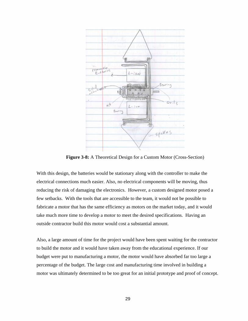
Figure 3-8: A Theoretical Design for a Custom Motor (Cross-Section)
With this design, the batteries would be stationary along with the controller to make the
electrical connections much easier. Also, no electrical components will be moving, thus
reducing the risk of damaging the electronics. However, a custom designed motor posed a
few setbacks. With the tools that are accessible to the team, it would not be possible to
fabricate a motor that has the same efficiency as motors on the market today, and it would
take much more time to develop a motor to meet the desired specifications. Having an
outside contractor build this motor would cost a substantial amount.
Also, a large amount of time for the project would have been spent waiting for the contractor
to build the motor and it would have taken away from the educational experience. If our
budget were put to manufacturing a motor, the motor would have absorbed far too large a
percentage of the budget. The large cost and manufacturing time involved in building a
motor was ultimately determined to be too great for an initial prototype and proof of concept.
30
Due to these factors, the team decided to use a motor that was already designed and
manufactured.
An off the shelf motor allowed for the selection of a motor from multiple manufacturers who
produce 400 W motors of varying weights and dimensions. The use of a mass-manufactured
motor meant the motor would be much more cost effective than a custom-fabricated motor.
These motors have been proven to work with the required loads and are available in many
sizes. Due to the fender design of the wheel assembly, the size of the motor only affected the
system by the amount of axle length it took up, as well as how much it weighed. The more
space left on the axle between the dropouts on the bicycle (135 mm spacing), the more space
there would be for energy storage.
4. SYSTEM INTEGRATION & TESTING
Once the design process and fabrication of Might-E Wheel was completed, it was necessary
to test the system with regard to its design specifications. The specifications tested were top
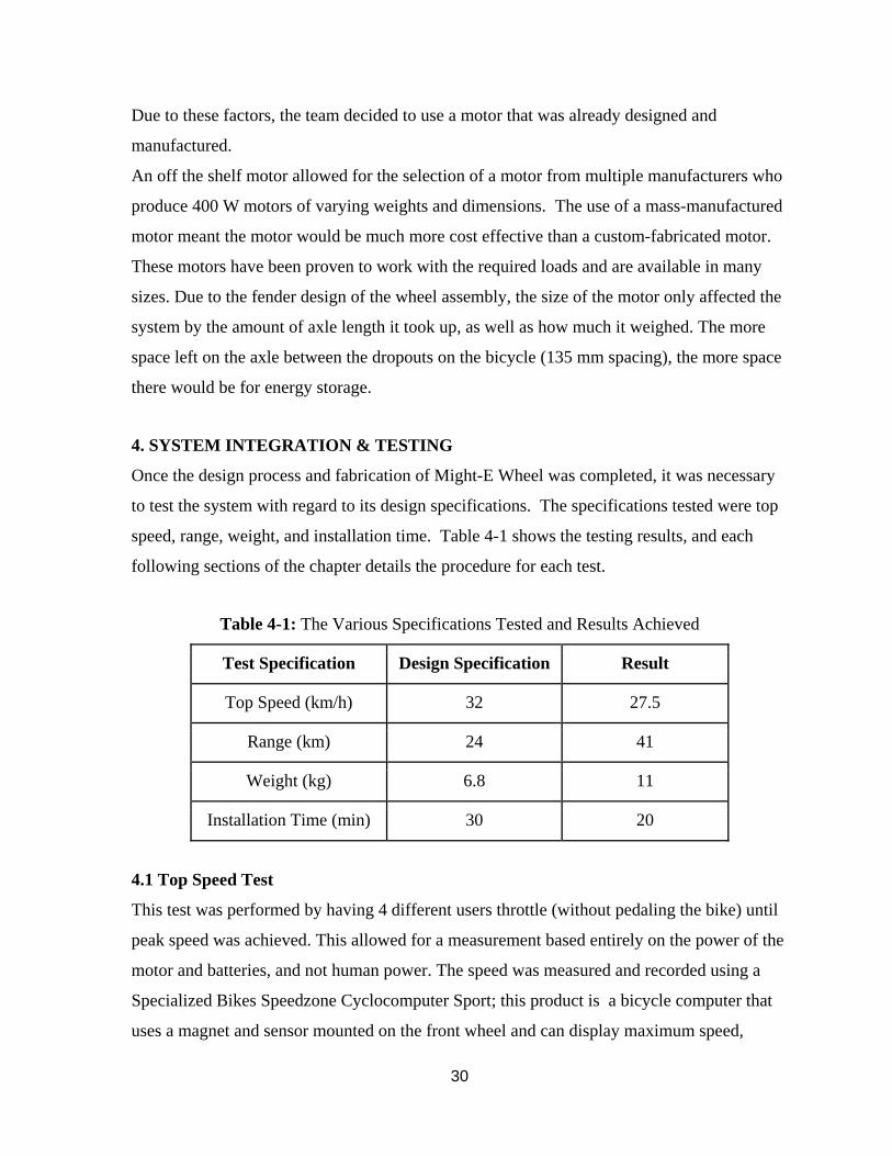
speed, range, weight, and installation time. Table 4-1 shows the testing results, and each
following sections of the chapter details the procedure for each test.
Table 4-1: The Various Specifications Tested and Results Achieved
Test Specification Design Specification Result
Top Speed (km/h) 32 27.5
Range (km) 24 41
Weight (kg) 6.8 11
Installation Time (min) 30 20
4.1 Top Speed Test
This test was performed by having 4 different users throttle (without pedaling the bike) until
peak speed was achieved. This allowed for a measurement based entirely on the power of the
motor and batteries, and not human power. The speed was measured and recorded using a
Specialized Bikes Speedzone Cyclocomputer Sport; this product is a bicycle computer that
uses a magnet and sensor mounted on the front wheel and can display maximum speed,
31
average speed, and range of a trip. The maximum speed achieved was 27.5 km/h. While this
fell slightly below the design speed of 32 km/h, it was deemed an acceptable top speed.
Higher speeds were reached when the riders used a combination of pedaling and throttling;
however, this test was meant to measure determine the speed achieved when using the
Might-E Wheel electric system alone.
4.2 Range Test
A test of range was conducted in order to find the total distance Might-E Wheel could carry a
bike and rider on a single battery charge. The calculations in Appendix D show that the
system was predicted to be able to transport the rider for 32 km. The range test was
completed by riding the bike around the Santa Clara University campus with the rider
moving at an average speed of 22 km/h. No human power was added by pedaling, leaving the
bike powered only by the motor. As few stops as possible were taken as possible because
acceleration takes additional energy.
The Specialized Bikes Speedzone Cyclocomputer Sport was used to monitor speed and track
distance. The Strava Cycling app was also used to verify distance, as well as time. Stops
were taken periodically in order to measure the nominal voltage of the battery pack and the
voltage of each individual battery. The batteries were charged to be relatively even and initial
voltage measurements of each battery, as well as the whole system were taken before
beginning the test.
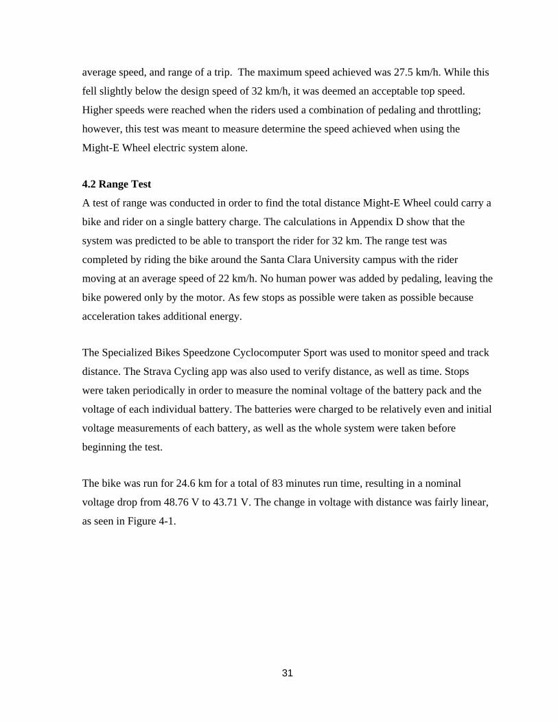
The bike was run for 24.6 km for a total of 83 minutes run time, resulting in a nominal
voltage drop from 48.76 V to 43.71 V. The change in voltage with distance was fairly linear,
as seen in Figure 4-1.
32
Figure 4-1: The Nominal Voltage of the Battery System with Respect to Distance, where y
Represents Voltage and x Represents Distance
The motor could still run after the 24.6 km of testing, but testing was concluded there for the
safety of the batteries and the rider. At this point, there had been a noticeable loss in power as
the bike could no longer achieve as high of a top speed, but the testing speed of 22 km/h was
still able to be maintained. The cutoff voltage of each individual battery is 7.2 V, or 28.8 V
nominal for the entire pack, but the motor cannot be powered properly once the pack voltage
drops below 40 V. This is also beneficial in keeping the batteries safe, as they never fully
reach their cutoff voltage. Ideally, this would also extend the battery life cycles.
The nominal voltage drop of the battery pack with distance can be represented by
𝑦 = −0.206𝑥 + 48.518, (eq. 4-1)
where y represents voltage and x represents distance.
33
Equation 4-1 was used to extrapolate the total range if the batteries were continued to be
drained to a nominal 40 V. It was found that at this voltage, the range would reach 41.35 km.
This range significantly exceeded the goal range of 24 km.
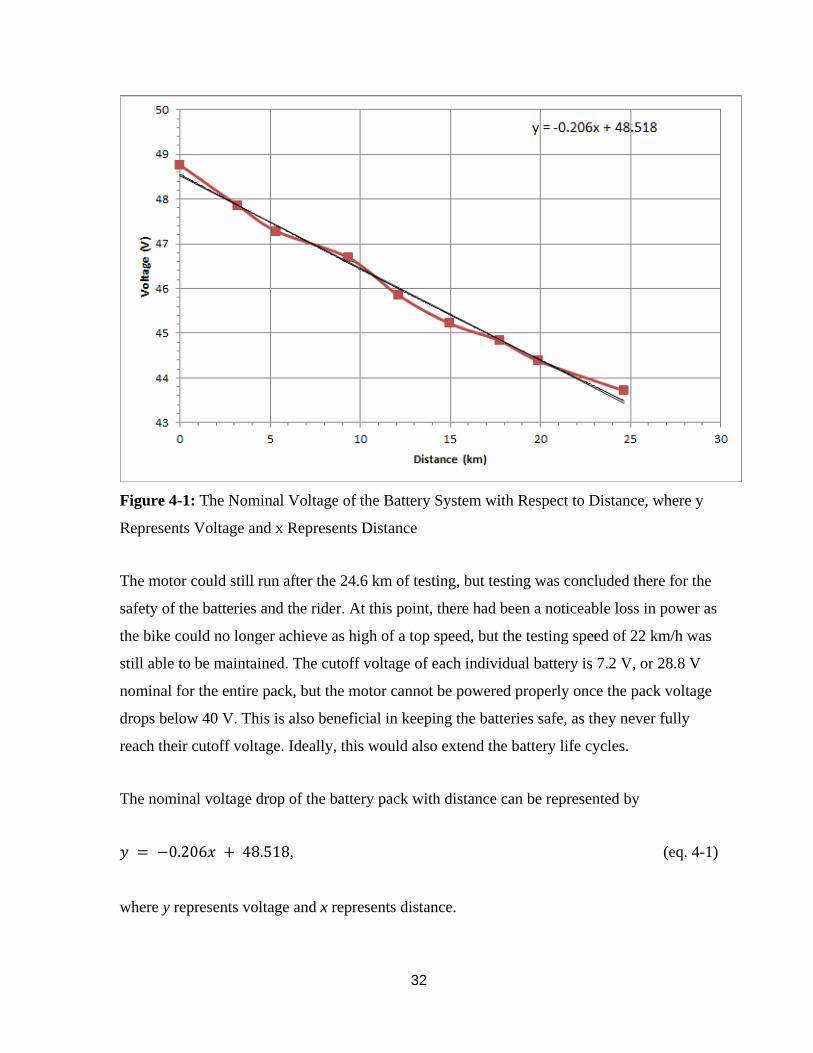
An additional concern was the even discharge of the batteries. For this reason, all of the
batteries were read for voltage at each stop. The voltage changes of each battery are shown in
Figure 4-2. The batteries discharged at a consistent rate, with all batteries discharging
similarly.
Figure 4-2: The Voltage of Each Battery with Respect to Distance
The total range could have been affected by the stops taken during testing. A total of 15 stops
were taken. These stops were not considered significant in the data, because an actual ride
would also include occasional stops, requiring the rider to accelerate additional times, and
consuming more power. The range specification was exceeded despite these stops and the
range may have been even longer with only the initial acceleration from zero.
34
4.3 Weight Test
The weight test was performed by simply placing the system with all its components onto a
scale and recording the result. The system weighed 11 kg. This was 4.2 kg heavier than the
intended weight, but this variation was not deemed to be important due to the achievement of
a good top speed and the fact that the weight of riders would likely vary by much more than
5 kg.
4.4 Installation Time Test
The installation time test was performed by preparing the Might-E Wheel as it would be sold
on the market, with all subsystems were assembled. The only installation necessary was to
secure the wheel onto the bike frame, mount and anchor the frame clamps to either side of
the wheel assembly, and mount the handlebar assembly on the handlebars of the bike. After
testing this with 3 different users, the maximum installation time was found to be 20 minutes.
This result was excellent due to it being shorter than the target installation time. This is one
of the most user-friendly features of the Might-E Wheel.
5. ENGINEERING STANDARDS AND REALISTIC CONSTRAINTS
All engineering projects are driven by constraints, and many projects must conform to certain
engineering standards. These constraints and standards define the technical boundaries that
project cannot cross.
Might-E Wheel will help take cars off the road, resulting in reduced emissions, improved
public health, and reduced spending on transportation. Adoption of Might-E Wheel will
make an impact across economic, social, health and safety, political, and environmental lines.
5.1 Health & Safety Impacts
The air we breathe has a large effect on our health. According to the American Lung
Association State of the Air 2011 report, over 154 million people, making up slightly over
half the nation, are exposed to highly polluted air every day [6]. With 75% of carbon
monoxide emissions resulting from automobiles, minimizing transportation by car serves as a
strong starting point to improve public health [7].
35
Researchers at the University of Wisconsin - Madison conducted a simulation modeling the
impact of eliminating automobile travel for round trips of 8 kilometers in distance or less in
11 United States metropolitan areas. The study concluded that eliminating these trips would
result in approximately 608 fewer deaths per year based on improved air quality alone [8].
The health impacts of air quality are also evident in the fact that 15% of children’s asthma
cases are linked to living near a busy road [9].
Might-E Wheel uses minimal electric power and creates zero road emissions, improving air
quality in highly populated areas. The extended range of Might-E Wheel allows for more
trips that can be made by electric bikes, thereby taking more cars off the road.
5.2 Social Impacts
Most automobile usage in the U.S. could be replaced, considering 69% of car trips are less
than 3.2 km (2 mi) [10]. In the first few minutes after an automobile is stated, it emits the
highest amount, making up almost a quarter of its emissions throughout an entire drive [11].
These short trips can easily and comfortably be replaced by electric bicycles. Replacing just
1 in 5 of these trips under 3.2 km with travel by Might-E Wheel instead of by automobile
would account for 14% of automobile usage in the U.S.
A study conducted by MIT on bicycle data in Lyon, France found that the speed of bicyclists
on manual bikes exceeds that of cars during rush hour by 50% and tends to match the speed
of cars in European inner cities [12]. The average of the rides recorded were 2.49 km in
distance over 14.7 minutes [13]. This distance could be expanded and time shortened by the
adoption of Might-E Wheel. Additionally, traveling with Might-E Wheel would be more time
efficient at busy hours and reduce the frustrations of sitting in traffic.
The added time, frustration, and cost of parking is also minimized by traveling by bicycle.
The space required to store one car can typically hold around 10 bicycles [14]. Since bicycles
are smaller, storage is easier and less expensive to provide. Adopting Might-E Wheel on to
an existing bike means that the bike will maintain its small dimensions and easy storability.
36
5.3 Economic Impacts
The Might-E Wheel has huge potential economic impacts through replacing more expensive
forms of transportation for commuters. In a 2006 study by the Center for Housing Policy,
regions from all around the nation were examined to compare housing and transportation
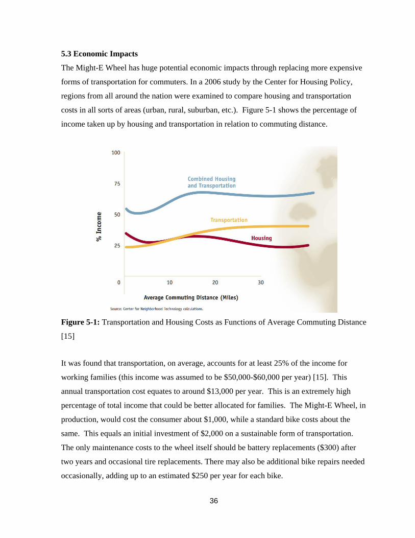
costs in all sorts of areas (urban, rural, suburban, etc.). Figure 5-1 shows the percentage of
income taken up by housing and transportation in relation to commuting distance.
Figure 5-1: Transportation and Housing Costs as Functions of Average Commuting Distance
[15]
It was found that transportation, on average, accounts for at least 25% of the income for
working families (this income was assumed to be $50,000-$60,000 per year) [15]. This
annual transportation cost equates to around $13,000 per year. This is an extremely high
percentage of total income that could be better allocated for families. The Might-E Wheel, in
production, would cost the consumer about $1,000, while a standard bike costs about the
same. This equals an initial investment of $2,000 on a sustainable form of transportation.
The only maintenance costs to the wheel itself should be battery replacements ($300) after
two years and occasional tire replacements. There may also be additional bike repairs needed
occasionally, adding up to an estimated $250 per year for each bike.
37
5.4 Environmental Impacts
Metropolitan areas have much worse air quality than their rural counterparts due to the high
volume of cars and other gas vehicles that constantly flow through them. In 2012, a
simulation was performed in order to understand the possible effects of eliminating 50% of
short car trips (< 8 km) in metropolitan areas and replacing them with bicycle rides. In the
simulation, the specific emissions of interest were fine particulates. It was found that this
reduction of automobile trips would reduce the average annual amount of fine particulates in
the air by 1.0-2.0% [16]. These results could be achieved by the use of the Might-E Wheel
and other electric bikes, reducing emissions and making the world healthier.
Further environmental issues stem from the batteries used in the Might-E Wheel. Lithium-
ion batteries were used for their excellent performance and rechargeability. Issues that arise
from these are that they cannot come in contact with fire or excessive water. Fire could
cause the batteries to explode while placing the batteries in water could cause the batteries to
rupture and release harmful gasses. Additionally, the batteries must be disposed of properly.
They are not allowed to be thrown away into the trash, since harmful chemicals can be
released into surrounding water and soil sources [17]. Instead, they should be recycled in
accordance with each state’s respective guidelines.
5.5 Manufacturability
With the Might-E Wheel’s current design the entire product is manufacturable without the
aid of computer automated machining (CAM). With the use of metal cutting tools and
fasteners the current model can be built and used as a working prototype. In regards to the
prototype’s current design this product cannot be mass-produced economically. The mass
production of the Might-E Wheel would require too much manufacturing time per product.
However, the Might-E Wheel’s first prototype would not be mass produced and if the Might-
E Wheel was in fact to go into mass production a separate design would be used. The
development time for the first prototype was fast due to the nature of the design and was
designed as such to be able to manufacture the product on-campus. For the second design to
be mass produced, the development time would increase significantly, yet the production
time per product would be greatly reduced in comparison to the first prototype. The
38
development time would greatly increase because the new design would have no battery
fender and would have the batteries within a case in the hub with the motor. To accomplish
this complex design, special aluminum molds, which also increases pre-production cost, need
to be cut with computer aided machining to create the needed components to house all of the
components. Once the molds are cut, it is only a matter of filling and refilling of the molds
and assembling the parts to create a production sequence. This process has a high pre-
production cost but this would be the only way that the Might-E Wheel can be mass
produced.
5.6 Realistic Constraints
Constraints to the design based on legal, size, speed, and range set the design parameters and
limitations.
5.6.1 State Laws
Laws and restrictions on electric bikes vary throughout the US and throughout the world.
This project is being done in California, so the California state laws were referred to for
restrictions. According to the California Highway Patrol, an electric (or “motorized”) bicycle
must have a motor that (1) outputs no more than 1000 W of power, (2) propels the bike no
faster than 32 km/h on level ground, and (3) increase the speed of the bicycle if human power
is propelling it faster than 32 km/h [18]. These all create constraints for the motor size and
speed of the system.
5.6.2 Size
A major engineering constraint of the project is size. We are volumetrically confined within
the hub of a 135 mm wheel axle spacing between the inside of each side of the fork.
Exceeding this space would disable the existing bicycle from operating properly, which
would make the project a failure. Therefore, it is certain that the motor, batteries, and
electrical equipment (control board, sensors) must be packaged within the hub of a bicycle
wheel.
39
5.6.3 Weight
Another engineering constraint to be considered is weight. The heavier the system is, the
more power is required to run it. High weight would also make the system bulky, difficult to
install, and difficult to transport. A lightweight, efficient system is desired in order to make a
usable and appealing system that maximizes performance.
5.6.4 Range
Range is a defining constraint of the system. Users will buy the product due to its ability to
transport them over a certain distance. If the product is unable to deliver a consistent and
worthwhile transportation distance, then appeal to the consumer becomes low. Therefore, it
is important to ensure that the product lives up to its target design range of 24 km on fully-
electric power.
5.6.5 Cost
Finally, cost is a heavy constraint on the project. This includes prototyping, testing, and final
product costs. The project has a specific budget (see Appendix B) that it cannot exceed. It
has received a finite amount of money from funding sources. Should these costs be exceeded
when ordering materials and prototyping, then the project is essentially dead. Additionally,
the goal of the project is to create a product that is appealing and comes at a fair cost to
consumers. Should a product be created that is many thousands of dollars, then it is very
unlikely that anyone would buy the product. The end cost must be kept in mind through the
entire design, fabrication, and testing stages.
6. SUMMARY AND CONCLUSION
6.1 Summary
The Might-E Wheel aims to improve upon current methods of transportation by designing a
wireless, electric rear wheel replacement that upgrades a bicycle to electric power. This was
accomplished by modifying a Golden Motor Smart Pie 4 motor, which was attached to a
wheel, and creating a housing that included Li-ion battery packs, wires, and electronics. This
assembly will communicate wirelessly with a throttle and brake lever that will attach to the
40
handlebars of the bike. The assembly will provide the user with both throttling and
regenerative braking capabilities to maximize the user experience and extend the range. The
project aspires to achieve an approachable, easily installable, and user-centric end product
that extends the range and improves the experience of human transportation.
6.2 Future Work
Going forward, there are a few improvements which could be made to Might-E Wheel had
there been more time. In the short term, more improvements should be made to lower the
market entry barrier to Might-E Wheel adoption and make it more widely adaptable for
users. In order to do this, the design should be further iterated upon to make the Might-E
Wheel easier to install and cheaper. In order to make Might-E Wheel a more viable
commuting option, the structure should be made smaller and lighter weight. As for the long
term, Might-E Wheel could be a catalyst in growing consciousness of green transportation
technologies. This could be done by partnering with ride-sharing programs that already exist
in cities to install Might-E Wheel onto shared bicycles. Converting these bicycles will cost
less than replacing them and encourage more people to commute by bike. Hopefully, wide-
scale adoption of Might-E Wheel will further spur individuals to shift towards electronic
means of transportation and ultimately lead to an improvement in our nation's infrastructure,
particularly with regards to bicycles.
41
BIBLIOGRAPHY
[1] Cabanatuan, Michael. "Tied up in traffic as bad as L.A.'s?." San Francisco Chronicle
(CA) 11 Feb. 2013, 5star-dot, Metro: A1. NewsBank. Web. 15 Oct. 2014.
[2] Neville, Tim. "Over the Alps on a Bike With a Boost." The New York Times. The New
York Times, 27 Aug. 2011. Web. 04 Nov. 2014.
[3] FlyKly cited 2015
[Available online at http://flykly.com/]
[4] Copenhagen Wheel cited 2015
[Available online at https://superpedestrian.com]
[5] Programable, Construir-en Controller, Magic Pie 3 Hub Motor E Bike Kit Y Smart Pie
Electric Bicycle Conversion Kit. Made-in-China.com. Web. 08 June 2015.
[6] "State of the Air 2011." American Lung Association. American Lung Association, 2011.
Web.
[7] "Cars, Trucks, Buses, and "Nonroad" Equipment." EPA. Environmental Protection
Agency. Web. 27 Apr. 2015.
[8] Grabow, Maggie L. et al. “Air Quality and Exercise-Related Health Benefits from
Reduced Car Travel in the Midwestern United States.” Environmental Health
Perspectives 120.1 (2012): 68–76. PMC. Web. 27 Apr. 2015.
[9] "A Breath of Fresh Air Please." The Lancet 377.9769 (2011): 875. The Lancet, 12 Mar.
2011. Web.
[10] Urban Transport. Transport Research & Innovation Portal. European Commission's
Directorate General for Mobility and Transport, July 2001. Web.
42
[11] “Air Quality and Exercise-Related Health Benefits from Reduced Car Travel in the
Midwestern States” Environmental Health Perspect. 2012 January. Web.
[12] "Cyclists Pedal Faster On Wednesdays, Reveals Smart Bike Data." MIT Technology
Review. MIT, 1 Dec. 2010. Web. 27 Apr. 2015.
[13] "Cyclists Pedal Faster On Wednesdays, Reveals Smart Bike Data." MIT Technology
Review. MIT, 1 Dec. 2010. Web. 27 Apr. 2015.
[14] Litman, Todd. "Evaluating Active Transport Benefits and Costs: Guide to Valuing
Walking and Cycling Improvements and Encouragement Programs." Victoria
Transport Policy Institute. Victoria Transport Policy Institute, 27 Feb. 2015. Web.
[15] Lipman, Barbara J. "A Heavy Load: The Combined Housing and Transportation
Burdens of Working Families." Center for Housing Policy (2006): 1-21. Nhc.org.
National Housing Conference + Center for Housing Policy. Web.
[16] Grabow, Maggie L., Scott N. Spak, Tracey Holloway, Brian Stone, Jr., Adam C.
Mednick, and Jonathan A. Patz. "EHP – Air Quality and Exercise-Related Health
Benefits from Reduced Car Travel in the Midwestern United States."
Ehp.niehs.nih.gov. Environmental Health Perspectives, 2 Nov. 2011. Web. 27 Apr.
2015.
[17] Agoston, George A. "Health and Safety Hazards of Art Materials." Leonardo 2.4 (1969):
373-82. Www.nrel.gov. National Renewable Energy Laboratory. Web. 27 Apr. 2015.
[18] "Motorcycles and Similar Vehicles." California Highway Patrol. CA.gov, 2014. Web.
09 Dec. 2014.
[19] "PSF to MPH Conversion Chart." Bristolite Daylighting Systems. N.p., n.d. Web. 26
May 2015.

43
[20] "Drag Coefficient." Drag Coefficient. The Engineering ToolBox, n.d. Web. 07 June
2015.
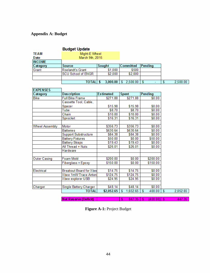
44
Appendix A: Budget
Figure A-1: Project Budget
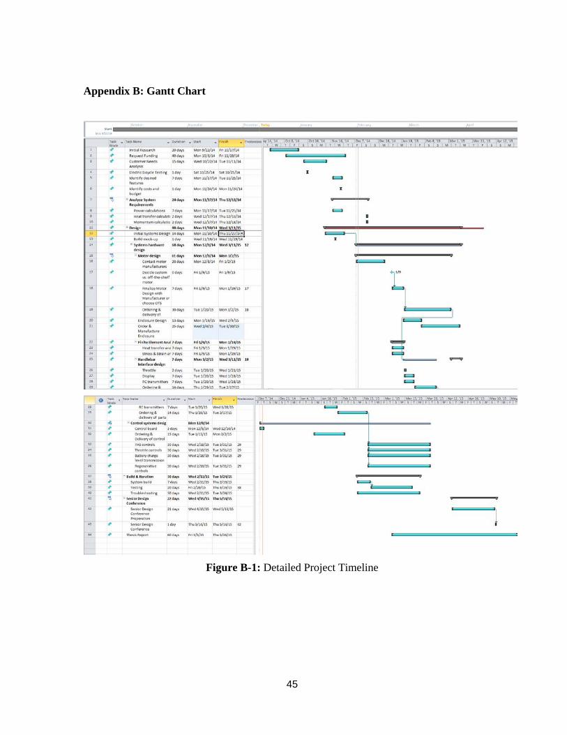
45
Appendix B: Gantt Chart
Figure B-1: Detailed Project Timeline
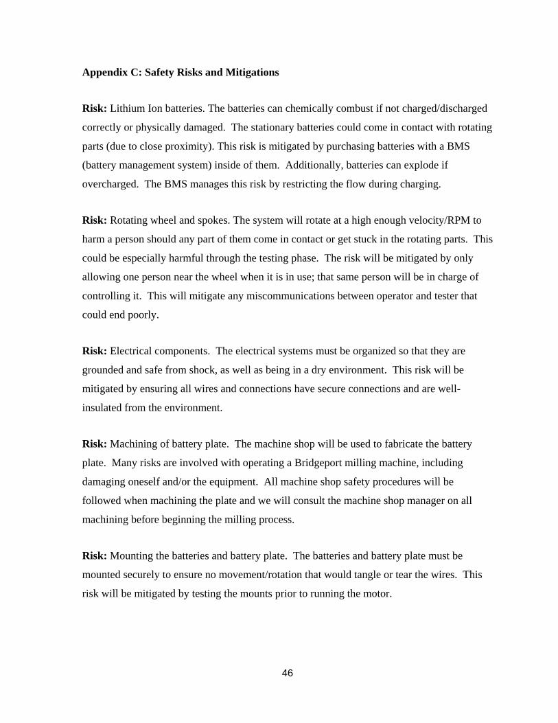
46
Appendix C: Safety Risks and Mitigations
Risk: Lithium Ion batteries. The batteries can chemically combust if not charged/discharged
correctly or physically damaged. The stationary batteries could come in contact with rotating
parts (due to close proximity). This risk is mitigated by purchasing batteries with a BMS
(battery management system) inside of them. Additionally, batteries can explode if
overcharged. The BMS manages this risk by restricting the flow during charging.
Risk: Rotating wheel and spokes. The system will rotate at a high enough velocity/RPM to
harm a person should any part of them come in contact or get stuck in the rotating parts. This
could be especially harmful through the testing phase. The risk will be mitigated by only
allowing one person near the wheel when it is in use; that same person will be in charge of
controlling it. This will mitigate any miscommunications between operator and tester that
could end poorly.
Risk: Electrical components. The electrical systems must be organized so that they are
grounded and safe from shock, as well as being in a dry environment. This risk will be
mitigated by ensuring all wires and connections have secure connections and are well-
insulated from the environment.
Risk: Machining of battery plate. The machine shop will be used to fabricate the battery
plate. Many risks are involved with operating a Bridgeport milling machine, including
damaging oneself and/or the equipment. All machine shop safety procedures will be
followed when machining the plate and we will consult the machine shop manager on all
machining before beginning the milling process.
Risk: Mounting the batteries and battery plate. The batteries and battery plate must be
mounted securely to ensure no movement/rotation that would tangle or tear the wires. This
risk will be mitigated by testing the mounts prior to running the motor.

47
Risk: RF signal transferring. The signal must be tested before being connected to the motor.
The signal could be wrongly amplified or filtered and result in the wrong signal being sent to
the motor. This risk will be mitigated by testing before hooking the receiver up to the motor.
Risk: Falling off the bike. When testing the bike, there is a chance that the user could fall off
and harm him/herself. This risk will be mitigated by wearing a helmet during testing.
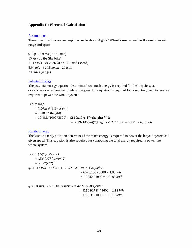
48
Appendix D: Electrical Calculations Assumptions These specifications are assumptions made about Might-E Wheel’s user as well as the user's desired range and speed. 91 kg - 200 lbs (the human) 16 kg - 35 lbs (the bike) 11.17 m/s - 40.2336 kmph - 25 mph (speed) 8.94 m/s - 32.18 kmph - 20 mph 20 miles (range) Potential Energy The potential energy equation determines how much energy is required for the bicycle system overcome a certain amount of elevation gain. This equation is required for computing the total energy required to power the whole system. E(h) = mgh = (107kg)*(9.8 m/s)*(h) = 1048.6* (height) = 1048.6/(1000*3600) = (2.19x10^(-4))*(height) kWh = (2.19x10^(-4))*(height) kWh * 1000 = .219*(height) Wh Kinetic Energy The kinetic energy equation determines how much energy is required to power the bicycle system at a given speed. This equation is also required for computing the total energy required to power the whole system. E(k) = (.5)*(m)*(v^2) = (.5)*(107 kg)*(v^2) = 53.5*(v^2) @ 11.17 m/s → 53.3 (11.17 m/s)^2 = 6675.136 joules = 6675.136 / 3600 = 1.85 Wh = 1.8542 / 1000 = .00185 kWh @ 8.94 m/s → 53.3 (8.94 m/s)^2 = 4259.92788 joules = 4259.92788 / 3600 = 1.18 Wh = 1.1833 / 1000 = .00118 kWh

49
Aerodynamics The aerodynamics equations are needed to determine how much energy is required, per mile, to overcome the force of drag of the given bicycle system. This equation is also required for computing the total energy required to power the whole system. *Assume frontal area of passenger and bicycle = .4 m^2 *Assume air density (ro) = 1.2 kg/m^3 *Assume drag coefficient = .9 [20] E(a) = .5 * (ro)*(aerodynamic drag coef)*(area)*(v^2) = .5* 1.2 * (.9) *(.4) * (v^2) = .216 (v^2) for E(a) measured in Joules/mile = .216 (v^2) *(1609/3600) = .09654 (v^2) v is measured in m/s = .09654 (v^2) /2 = .0482 (v^2) where v is measured in mph Starts/Stops The start/stop equations calculate the amount of energy needed to start or stop the given bicycle system. The value found was based off the Tesla Model S, so the equation used required an approximation based off the Tesla Model S data. This equation is also required for computing the total energy required to power the whole system. E(s) of bicycle approx 1/23 of E(s) of Tesla E(s) = (.158 * v^2) / 23 = .0068695652 * (v^2) v measured in mph = .0068695652 * (v^2) *.44704 = .00307097 (v^2) v measured in m/s Total Energy Required The total energy equations dictate how much energy the bicycle system will need given the desired range and speed. The total energy use was calculated for two different speeds. *Assume 500 m elevation change *Assume 10 start/stops @ 25 mph E(max) = E(h) + E(s) + [E(a) + #Start/Stops]L = [(.219)*500] + {[.0068695652 * (25^2)] + { .04827 (25^2) +10}*20miles = 917.16 Watt Hours @ 20 mph E(max) = E(h) + E(s) + [E(a) + #Start/Stops]L = [(.219)*500] + [.0068695652 * (20^2)] + { .04827 (20^2) +10}*20miles = 698.40 Watt Hours

50
Length of Trip The length of trip equations is just a reorganization of the total energy equation above. L = [E(max) - E(h) - E(s))] / [E(a) + #Start/Stops] Watt Hours Per Mile The equations below help determine how many watt hours will be used by the bicycle system per mile. The watt hours per mile required of the system was calculated for two different speeds.
@ 25 mph Wh/M = 917.16847 wh/20 miles = 45.85 Wh/M
@ 20 mph Wh/M = 698.407826 wh/20 miles = 34.92 Wh/M
Time/Range The Time/Range equations calculate how much time in total each of these systems could last. The calculations are broken down first by motor power then by speed. *Assuming 750 Watt Motor
@ 25 mph Energy = Power * Time 917.16847 Watt Hours = 750 Watts * Time Time = 1.22 Hours
@ 20 mph Energy = Power * Time 698.407826 Watt Hours = 750 Watts * Time Time = .93 Hours
*Assuming 500 Watt Motor
@ 25 mph Energy = Power * Time 917.16847 Watt Hours = 500 Watts * Time Time = 1.83 Hours
@ 20 mph Energy = Power * Time 698.407826 Watt Hours = 500 Watts * Time Time = 1.39 Hours
Extended Range The extended range calculations were performed to see the impact assisted pedaling would have on the bicycle system. The calculations are broken down first by motor power then by speed. *Assume humans produce 100 watts when pedaling *Assuming 750 Watt Motor
@ 25 mph Energy = Power * Time = 100 watts*1.078293 Hours = 107.82 watt hours
@ 20 mph Energy = Power * Time = 100 watts*.78662 Hours = 78.66 watt hours
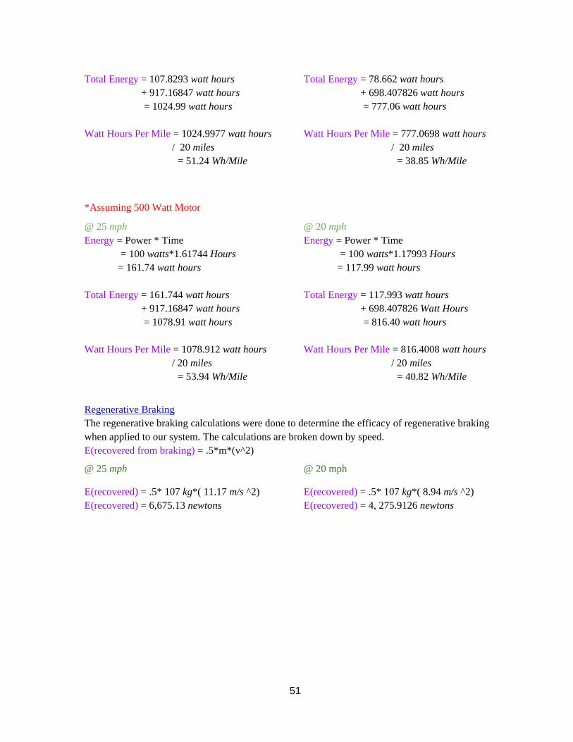
51
Total Energy = 107.8293 watt hours + 917.16847 watt hours = 1024.99 watt hours Watt Hours Per Mile = 1024.9977 watt hours / 20 miles = 51.24 Wh/Mile
Total Energy = 78.662 watt hours + 698.407826 watt hours = 777.06 watt hours Watt Hours Per Mile = 777.0698 watt hours / 20 miles = 38.85 Wh/Mile
*Assuming 500 Watt Motor
@ 25 mph Energy = Power * Time = 100 watts*1.61744 Hours = 161.74 watt hours Total Energy = 161.744 watt hours + 917.16847 watt hours = 1078.91 watt hours Watt Hours Per Mile = 1078.912 watt hours / 20 miles
= 53.94 Wh/Mile
@ 20 mph Energy = Power * Time = 100 watts*1.17993 Hours = 117.99 watt hours Total Energy = 117.993 watt hours + 698.407826 Watt Hours = 816.40 watt hours Watt Hours Per Mile = 816.4008 watt hours / 20 miles = 40.82 Wh/Mile
Regenerative Braking The regenerative braking calculations were done to determine the efficacy of regenerative braking when applied to our system. The calculations are broken down by speed. E(recovered from braking) = .5*m*(v^2)
@ 25 mph @ 20 mph
E(recovered) = .5* 107 kg*( 11.17 m/s ^2) E(recovered) = 6,675.13 newtons
E(recovered) = .5* 107 kg*( 8.94 m/s ^2) E(recovered) = 4, 275.9126 newtons
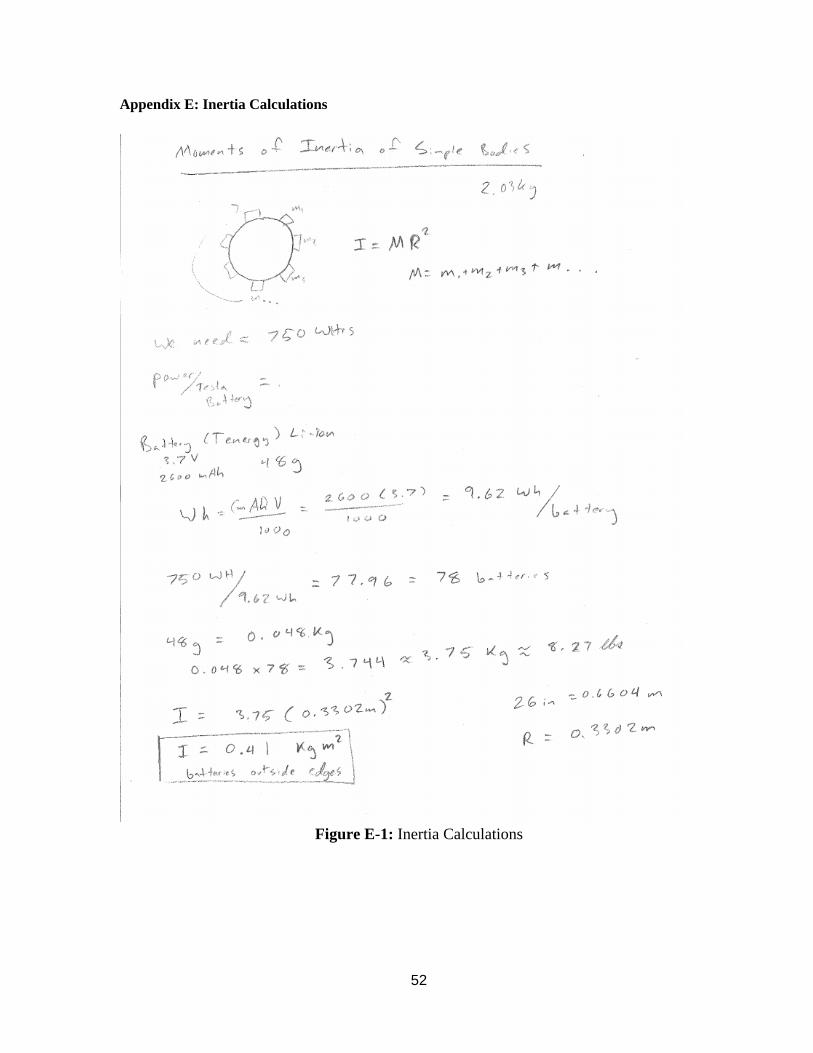
52
Appendix E: Inertia Calculations
Figure E-1: Inertia Calculations
53
Appendix F: Finite Element Analysis
Scenario 1: 80 km/h Crosswind
Description: This model represents the structure experiencing an 80 km/h wind normal to its
flat and wide surface. This wind speed was chosen because it is fairly severe; the system will
probably not have to perform under such conditions, but this analysis allows for a factor of
safety to be built in to the design.
External Loads: The 80 km/h crosswind was converted into a 322 Pa pressure using a
conversion table provided by Bristolite Daylighting Systems (Appendix G).
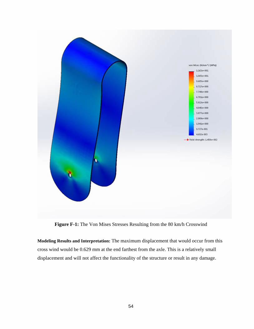
54
Figure F-1: The Von Mises Stresses Resulting from the 80 km/h Crosswind
Modeling Results and Interpretation: The maximum displacement that would occur from this
cross wind would be 0.629 mm at the end farthest from the axle. This is a relatively small
displacement and will not affect the functionality of the structure or result in any damage.
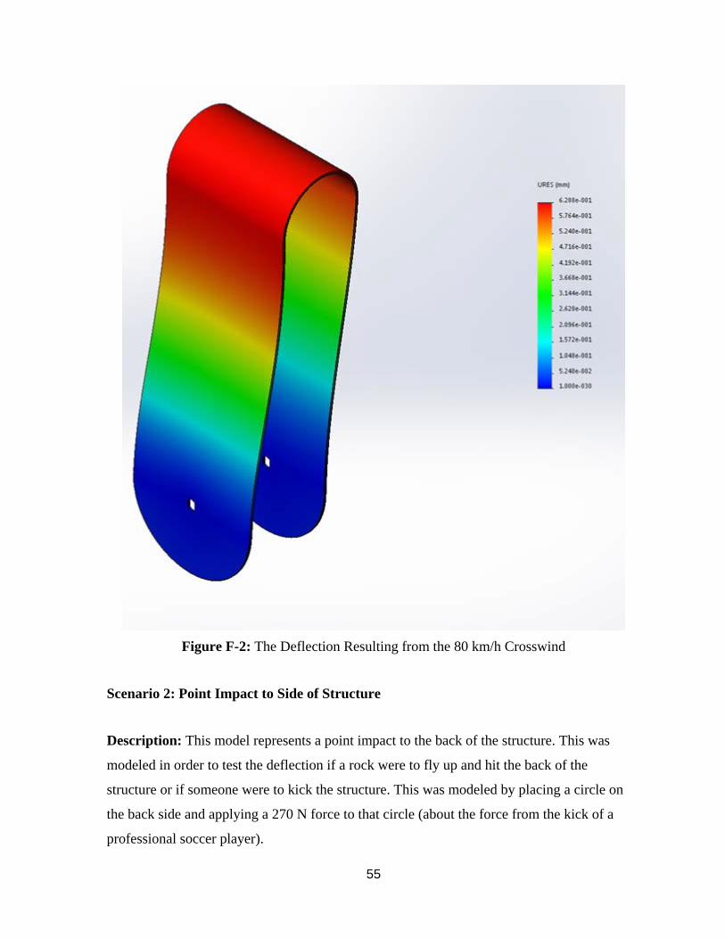
55
Figure F-2: The Deflection Resulting from the 80 km/h Crosswind
Scenario 2: Point Impact to Side of Structure
Description: This model represents a point impact to the back of the structure. This was
modeled in order to test the deflection if a rock were to fly up and hit the back of the
structure or if someone were to kick the structure. This was modeled by placing a circle on
the back side and applying a 270 N force to that circle (about the force from the kick of a
professional soccer player).
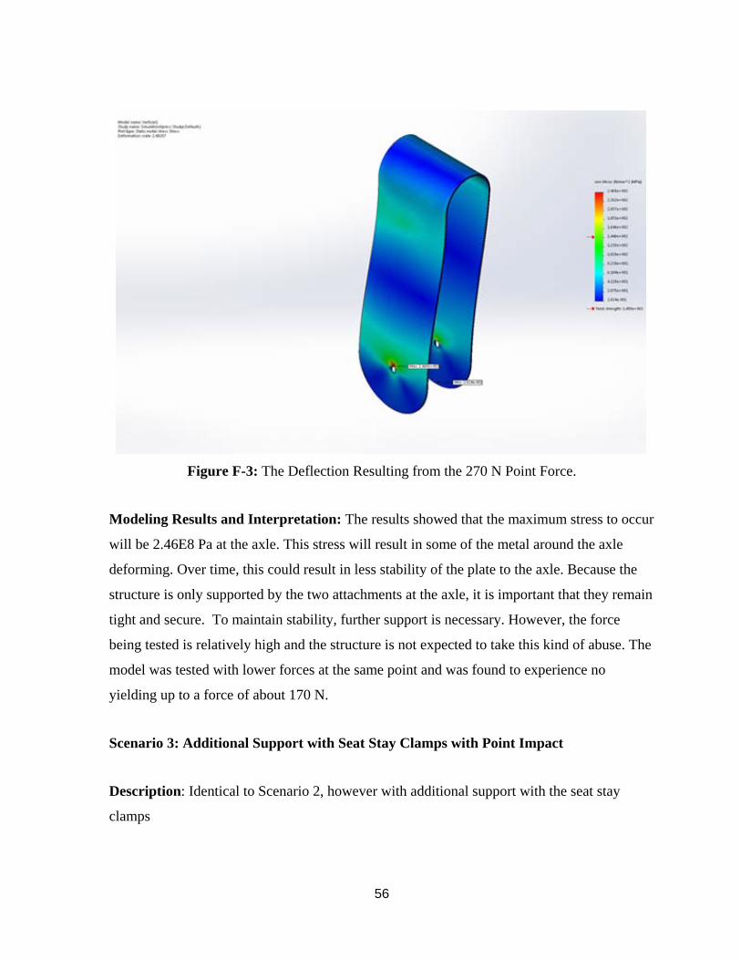
56
Figure F-3: The Deflection Resulting from the 270 N Point Force.
Modeling Results and Interpretation: The results showed that the maximum stress to occur
will be 2.46E8 Pa at the axle. This stress will result in some of the metal around the axle
deforming. Over time, this could result in less stability of the plate to the axle. Because the
structure is only supported by the two attachments at the axle, it is important that they remain
tight and secure. To maintain stability, further support is necessary. However, the force
being tested is relatively high and the structure is not expected to take this kind of abuse. The
model was tested with lower forces at the same point and was found to experience no
yielding up to a force of about 170 N.
Scenario 3: Additional Support with Seat Stay Clamps with Point Impact
Description: Identical to Scenario 2, however with additional support with the seat stay
clamps
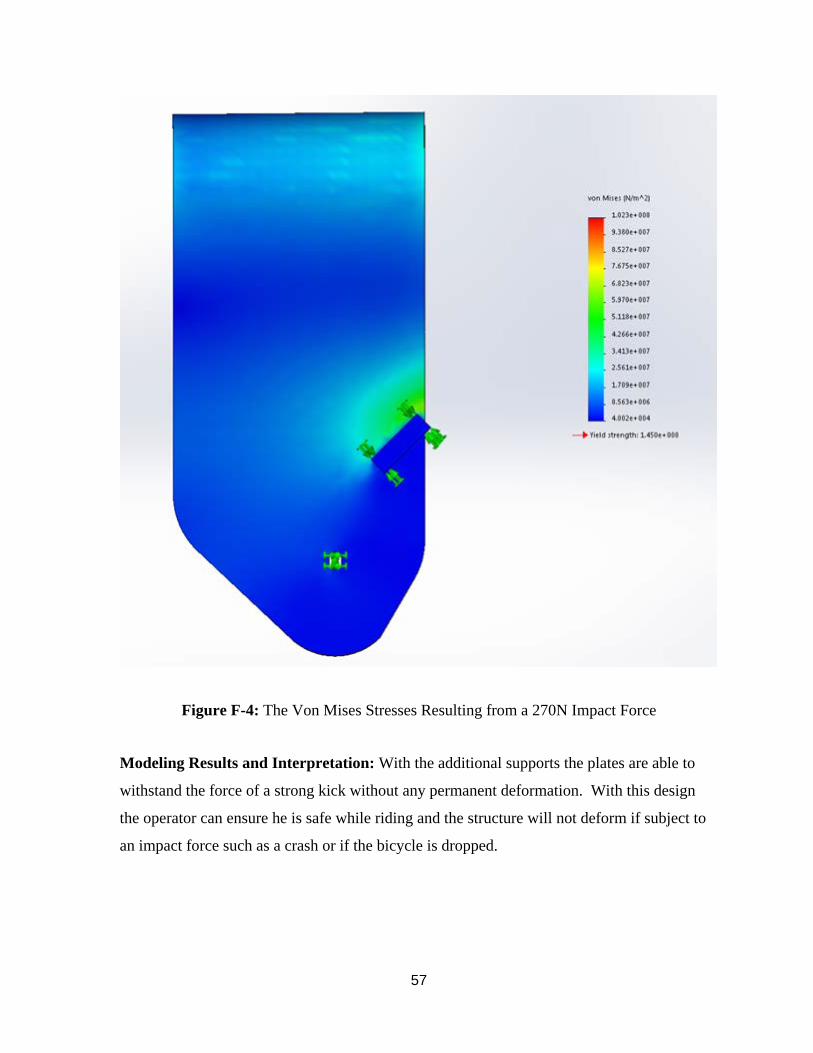
57
Figure F-4: The Von Mises Stresses Resulting from a 270N Impact Force
Modeling Results and Interpretation: With the additional supports the plates are able to
withstand the force of a strong kick without any permanent deformation. With this design
the operator can ensure he is safe while riding and the structure will not deform if subject to
an impact force such as a crash or if the bicycle is dropped.
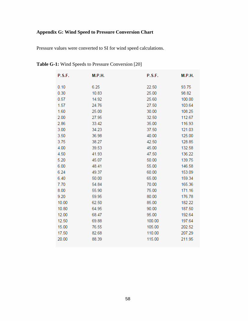
58
Appendix G: Wind Speed to Pressure Conversion Chart
Pressure values were converted to SI for wind speed calculations.
Table G-1: Wind Speeds to Pressure Conversion [20]
59
Appendix H: Business Plan
Introduction
Bicycles are a popular form of transport, especially for commuting in urban areas. Electric
bikes have been growing in popularity recently due to their ability to extend a cyclist’s range,
alleviate some of the workload, make for a consistent commute, and prevent sweating
through one’s work clothes. The electric bike market is comprised of two main groups:
electric bikes and conversion kits. Electric bikes are sold as fully completed products that are
ready to ride, and generally cost between $1,500 for the lowest grade and around $10,000 for
the highest grade. Conversion kits are made to install on a user’s previously owned bike, and
generally require mechanical and electrical aptitude. Most, when factoring in the cost of
batteries, cost around $800-$1,500. There is a wide variety of conversion kits that do not
include batteries and require the user to purchase, connect, and mount them. Only two
conversion kits (FlyKly and Copenhagen Wheel, both of which are in the pre-order stage
right now) include batteries and wireless electronics packaged together to ease installation
and improve the user’s experience. Might-E Wheel aims to achieve this goal and enhance
existing technologies and user experiences.
The current team (three mechanical engineers and one electrical engineer) would be able to
take over the roles of CEO, CTO, senior manufacturing manager, and senior electrical
engineer. In terms of additional personnel required, we would need a CFO, a marketing
manager, an accountant, two salespeople (one for online distribution and one for vendor
distribution), and two or three manufacturing engineers.
Goals and Objectives
The goal of the Might-E Wheel enterprise is to promote sustainable travel by making
commute by electric bicycle more approachable and accessible. With road congestion and
traffic prices increasing and irreversible environmental changes partially due to automobiles,
Might-E Wheel aims to be a catalyst in a transition to sustainable transportation.
60
Might-E Wheel seeks to appeal to the average consumer and intuitive for use by technical
novices. Ideally, Might-E Wheel would initially be adopted by bicycle owners looking to
commute farther and more comfortably. Might-E Wheel could also be implemented by
existing city bike programs that operate on a leasing system.
Product Description
Might-E Wheel is the first wireless rear-wheel replacement to convert bicycles from manual
to full-power electric. With an intuitive and quick installation, users can convert their
bicycles to full-power electric just by replacing their rear-wheel with Might-E Wheel and
attaching the handlebar assembly, consisting of the thumb throttle and regenerative brake.
Converting existing bicycles to electric will allow commuters to travel farther by bicycle,
resulting in more consistent commute times, reduced emissions on roads, and a more
enjoyable commute.
Potential Markets
Electric bikes appeal to a wide variety of consumers and markets. The primary target
audience would be urban commuters seeking to travel 24 km or less to work. This audience
would want to buy the product due to its ease of installation and ability to transport them to
their destination consistently and comfortably. Another target market is senior citizens. Many
people above the age of 65 enjoy being outside and taking fun trips, however the majority are
too weak to pedal a bike for long or up a hill. The product would enable them to have fun
bike rides outdoors while not wearing on their body at all. A final target audience would be
people charged with a DUI. These people generally have their license suspended for a period
of time, yet need a proper form of transportation. Might-E Wheel would provide them with a
solution that enables them to ride a bike for long distances to get them where they need to go.
Competition
Might-E Wheel is competing for a similar market as the FlyKly Smart Wheel and the
Superpedestrian Copenhagen Wheel. These products are both fully enclosed systems that
encompass the motor, controls, and batteries within the hub of the wheel. Both FlyKly and
Copenhagen Wheel entered the market through a crowdfunding campaign. FlyKly has
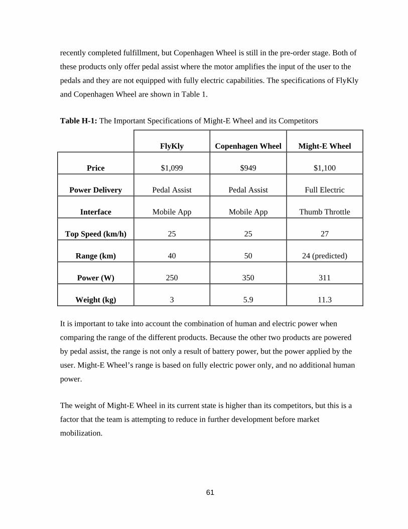
61
recently completed fulfillment, but Copenhagen Wheel is still in the pre-order stage. Both of
these products only offer pedal assist where the motor amplifies the input of the user to the
pedals and they are not equipped with fully electric capabilities. The specifications of FlyKly
and Copenhagen Wheel are shown in Table 1.
Table H-1: The Important Specifications of Might-E Wheel and its Competitors
FlyKly Copenhagen Wheel Might-E Wheel
Price $1,099 $949 $1,100
Power Delivery Pedal Assist Pedal Assist Full Electric
Interface Mobile App Mobile App Thumb Throttle
Top Speed (km/h) 25 25 27
Range (km) 40 50 24 (predicted)
Power (W) 250 350 311
Weight (kg) 3 5.9 11.3
It is important to take into account the combination of human and electric power when
comparing the range of the different products. Because the other two products are powered
by pedal assist, the range is not only a result of battery power, but the power applied by the
user. Might-E Wheel’s range is based on fully electric power only, and no additional human
power.
The weight of Might-E Wheel in its current state is higher than its competitors, but this is a
factor that the team is attempting to reduce in further development before market
mobilization.
62
Sales and Marketing Strategies
Might-E Wheel plans to enter the market through a crowdfunding campaign. The campaign
will allow customers to place pre-orders through the Might-E Wheel website. A transparent
fulfillment date will be given upon ordering to prevent frustrated customers. Beginning sales
in a pre-order stage will allow Might-E Wheel to test market interest while acquiring funds
for manufacturing and initial business costs. The company can also continue to develop and
improve on the technology in order to deliver the best possible product to the customer.
Might-E Wheel will work with press to gain publicity and awareness going into the
crowdfunding campaign. The company will also make a vision video in order to share the
possible uses of the product with consumers.
From there, Might-E Wheel will work with e-commerce sites to minimize costs of sales and
distribution in the early phases. Many of these websites sell “cool” tech products, and Might-
E Wheel will likely appeal to these consumers.
Once an initial market has been established and brand awareness has developed, Might-E
Wheel will move into bicycle stores. With Might-E Wheel, consumers can buy a manual bike
and use it for its traditional purposes, as well as for electric transportation when necessary.
Manufacturing Plans
Might-E Wheel is comprised of multiple aluminum pieces that are easily manufactured. To
achieve the volume and price that is needed, the separate pieces will be cut by outsourcing to
a local CNC machine shop. This shop will be able to provide accurate cutting and be able to
replicate each part in volume. Once the parts are cut by the shop, all of the pieces will be
assembled by the manufacturing engineers and overseen by the senior engineer to ensure a
safe and consistent product. Each Might-E Wheel will take approximately five hours to cut
all the necessary pieces and another two hours to assemble each package.
Included in the Might-E Wheel package is a thumb throttle and regenerative braking
assembly that will need to be manufactured. For this specific piece it will be a molded
casing, which the thumb control will install into. This molded piece will be outsourced to a
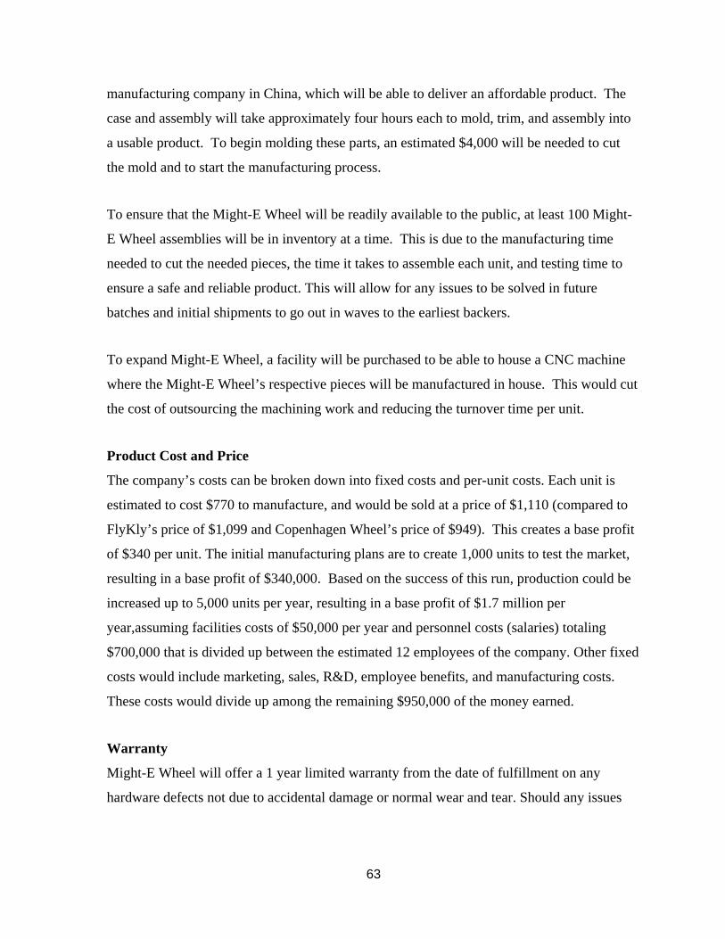
63
manufacturing company in China, which will be able to deliver an affordable product. The
case and assembly will take approximately four hours each to mold, trim, and assembly into
a usable product. To begin molding these parts, an estimated $4,000 will be needed to cut
the mold and to start the manufacturing process.
To ensure that the Might-E Wheel will be readily available to the public, at least 100 Might-
E Wheel assemblies will be in inventory at a time. This is due to the manufacturing time
needed to cut the needed pieces, the time it takes to assemble each unit, and testing time to
ensure a safe and reliable product. This will allow for any issues to be solved in future
batches and initial shipments to go out in waves to the earliest backers.
To expand Might-E Wheel, a facility will be purchased to be able to house a CNC machine
where the Might-E Wheel’s respective pieces will be manufactured in house. This would cut
the cost of outsourcing the machining work and reducing the turnover time per unit.
Product Cost and Price
The company’s costs can be broken down into fixed costs and per-unit costs. Each unit is
estimated to cost $770 to manufacture, and would be sold at a price of $1,110 (compared to
FlyKly’s price of $1,099 and Copenhagen Wheel’s price of $949). This creates a base profit
of $340 per unit. The initial manufacturing plans are to create 1,000 units to test the market,
resulting in a base profit of $340,000. Based on the success of this run, production could be
increased up to 5,000 units per year, resulting in a base profit of $1.7 million per
year,assuming facilities costs of $50,000 per year and personnel costs (salaries) totaling
$700,000 that is divided up between the estimated 12 employees of the company. Other fixed
costs would include marketing, sales, R&D, employee benefits, and manufacturing costs.
These costs would divide up among the remaining $950,000 of the money earned.
Warranty
Might-E Wheel will offer a 1 year limited warranty from the date of fulfillment on any
hardware defects not due to accidental damage or normal wear and tear. Should any issues
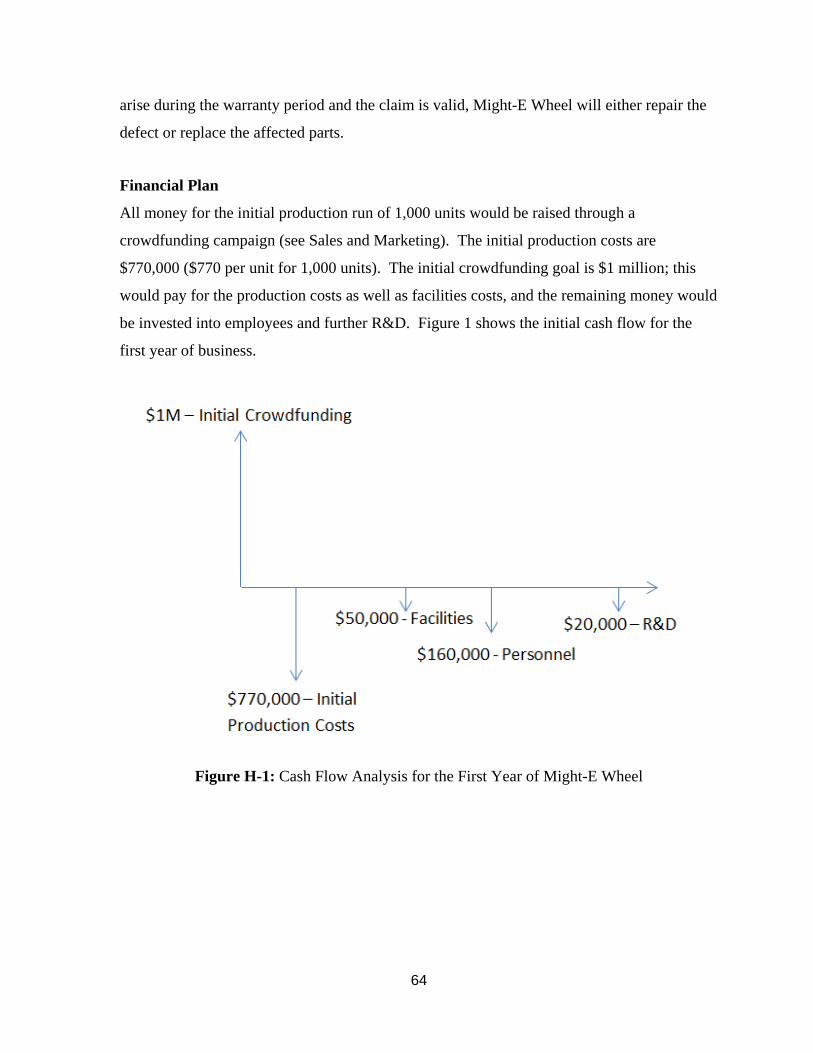
64
arise during the warranty period and the claim is valid, Might-E Wheel will either repair the
defect or replace the affected parts.
Financial Plan
All money for the initial production run of 1,000 units would be raised through a
crowdfunding campaign (see Sales and Marketing). The initial production costs are
$770,000 ($770 per unit for 1,000 units). The initial crowdfunding goal is $1 million; this
would pay for the production costs as well as facilities costs, and the remaining money would
be invested into employees and further R&D. Figure 1 shows the initial cash flow for the
first year of business.
Figure H-1: Cash Flow Analysis for the First Year of Might-E Wheel
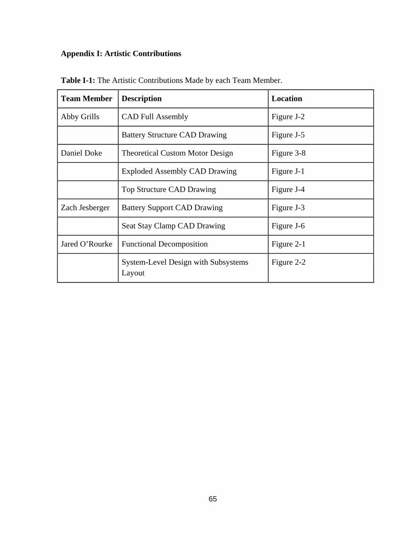
65
Appendix I: Artistic Contributions
Table I-1: The Artistic Contributions Made by each Team Member.
Team Member Description Location
Abby Grills CAD Full Assembly Figure J-2
Battery Structure CAD Drawing Figure J-5
Daniel Doke Theoretical Custom Motor Design Figure 3-8
Exploded Assembly CAD Drawing Figure J-1
Top Structure CAD Drawing Figure J-4
Zach Jesberger Battery Support CAD Drawing Figure J-3
Seat Stay Clamp CAD Drawing Figure J-6
Jared O’Rourke Functional Decomposition Figure 2-1
System-Level Design with Subsystems Layout
Figure 2-2
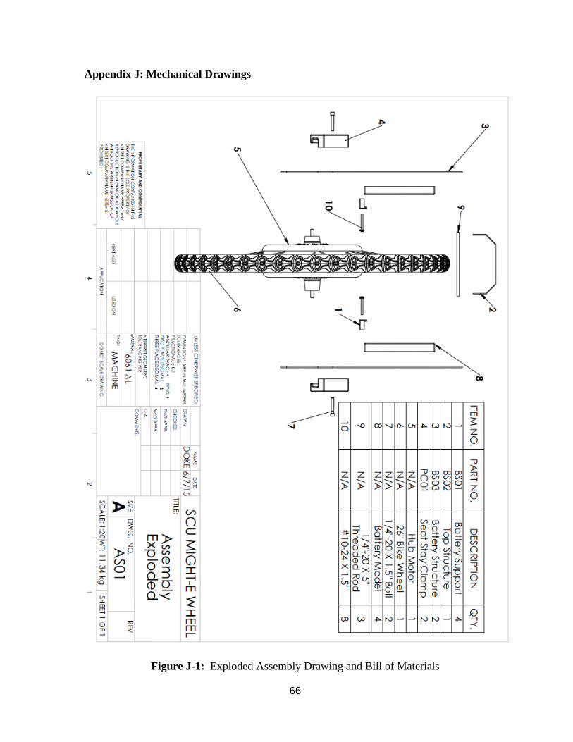
66
Appendix J: Mechanical Drawings
Figure J-1: Exploded Assembly Drawing and Bill of Materials
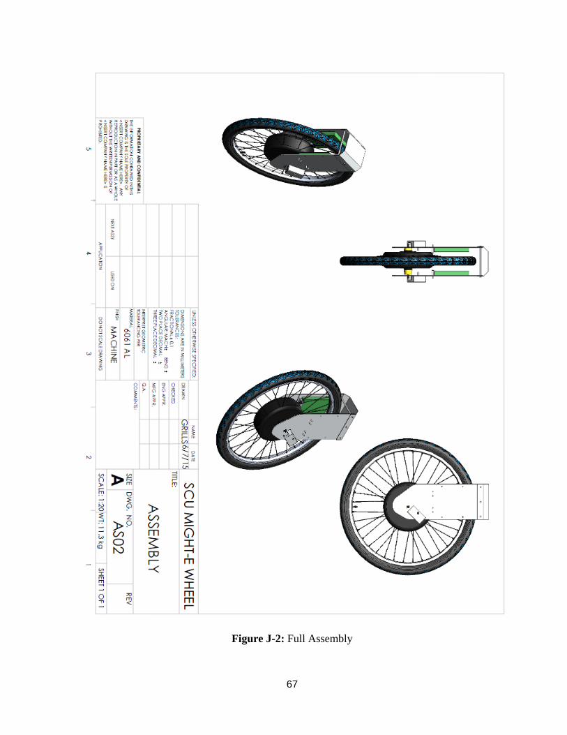
67
Figure J-2: Full Assembly
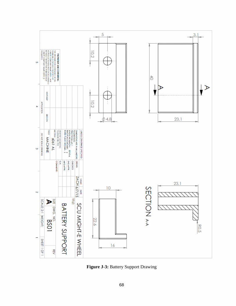
68
Figure J-3: Battery Support Drawing
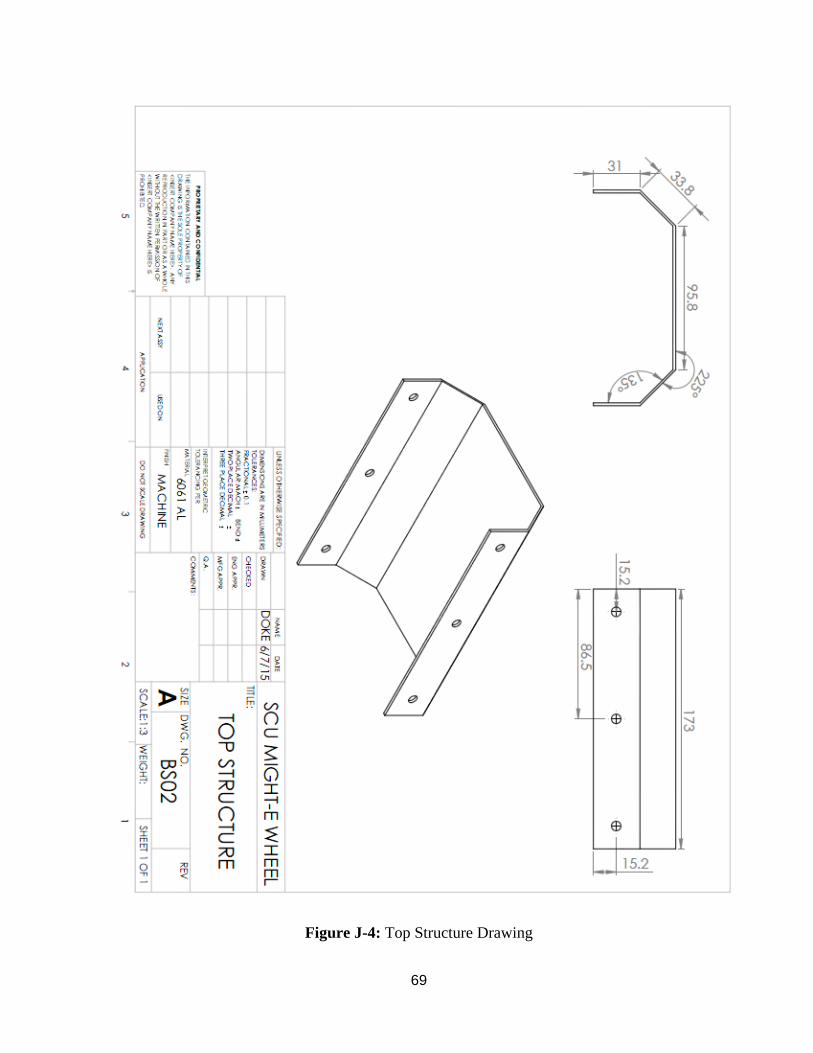
69
Figure J-4: Top Structure Drawing
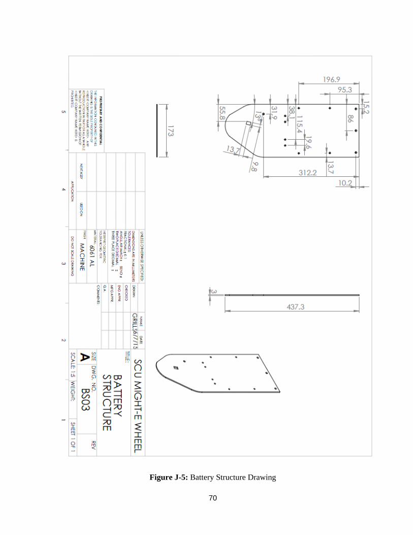
70
Figure J-5: Battery Structure Drawing
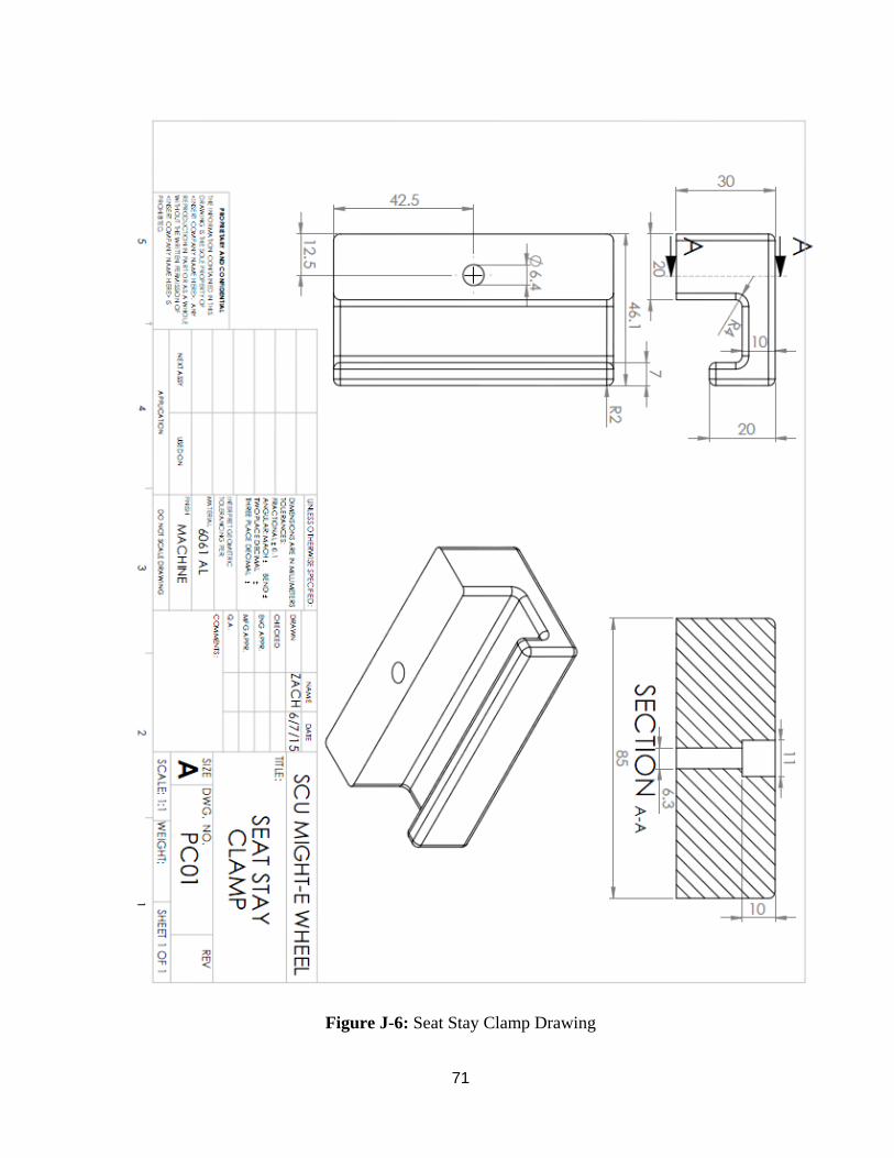
71
Figure J-6: Seat Stay Clamp Drawing