Embed Size (px)
Citation preview

650mm R/C High Performance Racing Sailboat
For more information about the boatand the DragonForce 65 racing class. visit:
www.dfracing.world
Specification• Length: 650mm• Beam: 116.5mm• Rig Height: 915mm• Overall height: 1338mm• RTR total weight: 1200g (Batteries not included)• Sail area (Mainsail): 1460cm²• Sail area (Jib): 766cm²• Sail area (overall): 2226cm²• Hull material: Moulded ABS with painted finish with logo stickers• Supplied in two versions: RTR version (8815) with transmitter & receiver ARTR version (8815A) with no radio gear• RTR version requires 4pcs AA battery for transmitter & 4pcs AA battery for receiver
I N S T R U C T I O N M A N U A L
2
INSTRUCTION MANUALTHIS MODEL IS NOT A TOY. THESE INSTRUCTIONS SHOULD BE READ BY A SUPERVISING ADULT
DRAGONFORCE 65 2.4GHz R/C RACING SAILBOATThis Instruction Manual covers models 8815(RTR) & 8815A(ARTR)
IMPORTANT:
- This is not a toy. Assembly and operating of this boat requires adult supervision.
- Please take time to read these instructions carefully and completely before attempting to operate your model. This manual contains the instructions you need to safely build operate and maintain you R/C sailboat.
ITEMS REQUIRED FOR COMPLETION:
- RTR version (8815) requires 8 x ‘AA’ batteries (dry cell or rechargeable). (Four for the transmitter, four for the Receiver Battery Box).
- Thin CA glue (cyanoacrylate/superglue).
- A pair of thin nosed pliers and a sharp craft knife or scalpel.
BOX CONTENTS
Deck Eye 2
Deck Eye 3
Deck Eye 4 (Hook)
Deck Eye 5
Deck Eye 6
Sliding Deck Plate Mainsheet Bridle On/Off Switch
Mast - lower, long section
Jib Mainsail
Jib Boom
Main Boom
Mast Stub
Deck Hatch Cover
Adhesive Deck Patches
Fittings Pack
Hull
Deck Eye 8
Deck Eye 7
Deck Eye 9
Deck Eye 10
Mast - short, upper section
RudderKeel Bulb
Keel
Boat Stand Components
Mast Socket
I N S T R U C T I O N M A N U A L
3
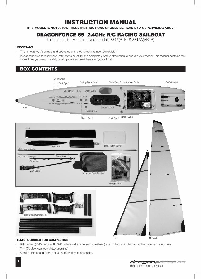
BOW The front of the boat.
STERN The back of the boat.
PORT This is the left side of the boat when viewed from the Stern.
STARBOARD This is the right side of the boat when viewed from the Stern.
HULL The body of the boat.
DECK The upper surface of the Hull.
KEEL A weighted blade that protrudes from the bottom of the hull as a means of providing lateral stability.
RUDDER The hinged vertical blade mounted at the Stern used as a steering device.
BASIC BOAT TERMINOLOGY
FORESTAY
JIB SAIL
LUFF (front edge of sail)
JIB BOOM
COUNTERWEIGHT
HULL
KEEL
KEEL BULB
RUDDER
MAIN BOOM
BOOM VANG
MAINSHEET
BACKSTAY
MAINSAIL
BACKSTAY CRANE
JIBSHEET
LEECH (back edge of sail)
BOWSIE (adjuster)
JIB TOPPING LIFT
GOOSENECK
FORESTAY FITTING
LUFF RING
I N S T R U C T I O N M A N U A L
4
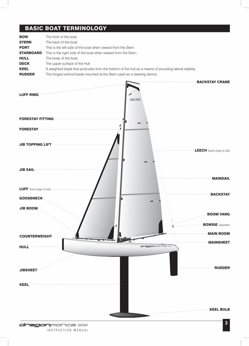
1 Identify all stand components from box. Note: The nuts, bolts and EVA foam support pads are located in the fittings pack.
2 Bolt the plastic moulded components together with the twelve nut & bolts supplied.
3 Construct the leg sections. Note: The leg sections are the four longer tubes.
4 Fit the three stretcher tubes.
5 Fix the soft EVA foam supports to the top surface of the stand to protect the Hull from scratches.
DISPLAY STAND ASSEMBLY
1 2 3 4 5
1 Adjust both sides of the Mainsheet Bridle so they are each 45mm from the Deck Eye to the ring.
2 From the fittings pack take out the Mainsheet Bridle Plate and a plastic Bowsie. Cut a 130mm length of Dyneema cord, tie one end to the small hole in the Mainsheet Bridle Plate, pass the other end through the Bowsie (see opposite), through the ring and back to the bowsie. Adjust to a length of 65mm, as shown in Photo 2 below, with the Bowsie positioned approximately half way along the length and tie off at the bowsie. Trim off the spare end.
MAINSHEET BRIDLE
1 2
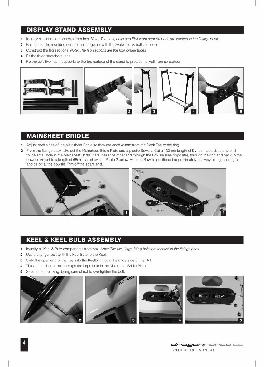
1 Identify all Keel & Bulb components from box. Note: The two, large fixing bolts are located in the fittings pack.
2 Use the longer bolt to fix the Keel Bulb to the Keel.
3 Slide the open end of the keel into the Keelbox slot in the underside of the Hull.
4 Thread the shorter bolt through the large hole in the Mainsheet Bridle Plate.
5 Secure the top fixing, being careful not to overtighten the bolt.
KEEL & KEEL BULB ASSEMBLY
2 3 4
45mm
65mm
5
I N S T R U C T I O N M A N U A L
5
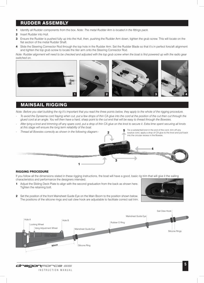
1 Identify all Rudder components from the box. Note: The metal Rudder Arm is located in the fittings pack.
2 Insert Rudder into Hull.
3 Ensure the Rudder is pushed fully up into the Hull, then, pushing the Rudder Arm down, tighten the grub screw. This will locate on the flat section of the metal Rudder Shaft.
4 Slide the Steering Connector Rod through the top hole in the Rudder Arm. Set the Rudder Blade so that it’s in perfect fore/aft alignment and tighten the top grub screw to locate the tiler arm onto the Steering Connector Rod.
Note: Rudder alignment will need to be checked and adjusted with the top grub screw when the boat is first powered up with the radio gear switched on.
RUDDER ASSEMBLY
1 2 3 4
Note: Before you start building the rig it’s important that you read the three points below, they apply to the whole of the rigging procedure.
- To avoid the Dyneema cord fraying when cut, put a few drops of thin CA glue into the cord at the position of the cut then cut through the glued cord at an angle. You will then have a hard, sharp point to the cut end that will be easy to thread through the Bowsies.
- After tying a knot and trimming off any spare cord, put a drop of thin CA glue on the knot to secure it. Extra time spent securing all knots at this stage will ensure the long term reliability of the boat.
- Thread all Bowsies correctly as shown in the following diagram:-
MAINSAIL RIGGING
RIGGING PROCEDURE
If you follow all the dimensions stated in these rigging instructions, the boat will have a good, basic rig trim that will give it the sailing characteristics and performance the designers intended.
1 Adjust the Sliding Deck Plate to align with the second graduation from the back as shown here. Tighten the retaining bolt.
2 Set the position of the front Mainsheet Guide Eye on the Main Boom to the position shown below. The positions of the silicone rings and sail clew hook are adjustable to facilitate correct sail trim.
1
2
3
4
5 Tie a substantial knot in the end of the cord, trim off any surplus cord, apply a drop of CA glue to the knot and pull back into the circular recess in the Bowsie.
80mm
Hole A
Locking Wheel
Vang Adjustment Wheel
Hole B
Mainsheet Guide Eye
Mainsheet Guide Eye
Rubber O Ring
Sail Clew Hook
Silicone Rings
Silicone Ring
I N S T R U C T I O N M A N U A L
6
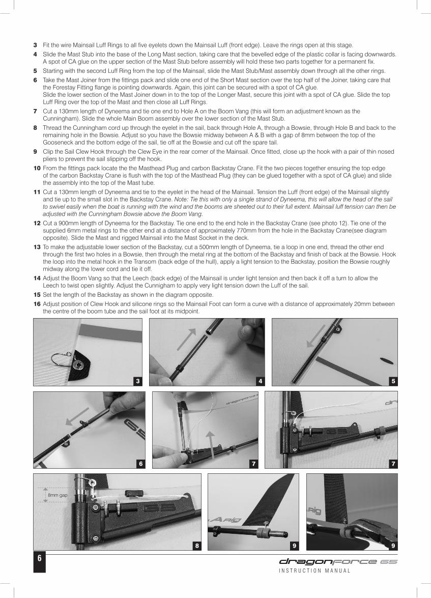
3 Fit the wire Mainsail Luff Rings to all five eyelets down the Mainsail Luff (front edge). Leave the rings open at this stage.
4 Slide the Mast Stub into the base of the Long Mast section, taking care that the bevelled edge of the plastic collar is facing downwards. A spot of CA glue on the upper section of the Mast Stub before assembly will hold these two parts together for a permanent fix.
5 Starting with the second Luff Ring from the top of the Mainsail, slide the Mast Stub/Mast assembly down through all the other rings.
6 Take the Mast Joiner from the fittings pack and slide one end of the Short Mast section over the top half of the Joiner, taking care that the Forestay Fitting flange is pointing downwards. Again, this joint can be secured with a spot of CA glue. Slide the lower section of the Mast Joiner down in to the top of the Longer Mast, secure this joint with a spot of CA glue. Slide the top Luff Ring over the top of the Mast and then close all Luff Rings.
7 Cut a 130mm length of Dyneema and tie one end to Hole A on the Boom Vang (this will form an adjustment known as the Cunningham). Slide the whole Main Boom assembly over the lower section of the Mast Stub.
8 Thread the Cunningham cord up through the eyelet in the sail, back through Hole A, through a Bowsie, through Hole B and back to the remaining hole in the Bowsie. Adjust so you have the Bowsie midway between A & B with a gap of 8mm between the top of the Gooseneck and the bottom edge of the sail, tie off at the Bowsie and cut off the spare tail.
9 Clip the Sail Clew Hook through the Clew Eye in the rear corner of the Mainsail. Once fitted, close up the hook with a pair of thin nosed pliers to prevent the sail slipping off the hook.
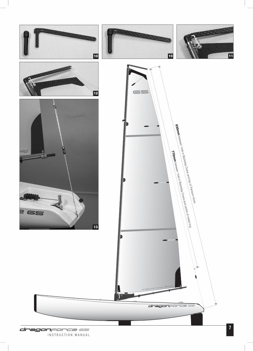
10 From the fittings pack locate the the Masthead Plug and carbon Backstay Crane. Fit the two pieces together ensuring the top edge of the carbon Backstay Crane is flush with the top of the Masthead Plug (they can be glued together with a spot of CA glue) and slide the assembly into the top of the Mast tube.
11 Cut a 130mm length of Dyneema and tie to the eyelet in the head of the Mainsail. Tension the Luff (front edge) of the Mainsail slightly and tie up to the small slot in the Backstay Crane. Note: Tie this with only a single strand of Dyneema, this will allow the head of the sail to swivel easily when the boat is running with the wind and the booms are sheeted out to their full extent. Mainsail luff tension can then be adjusted with the Cunningham Bowsie above the Boom Vang.
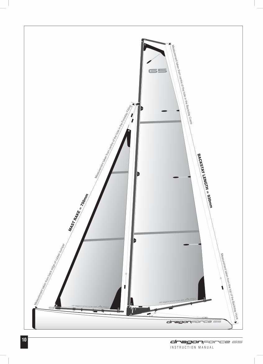
12 Cut a 900mm length of Dyneema for the Backstay. Tie one end to the end hole in the Backstay Crane (see photo 12). Tie one of the supplied 6mm metal rings to the other end at a distance of approximately 770mm from the hole in the Backstay Crane(see diagram opposite). Slide the Mast and rigged Mainsail into the Mast Socket in the deck.
13 To make the adjustable lower section of the Backstay, cut a 500mm length of Dyneema, tie a loop in one end, thread the other end through the first two holes in a Bowsie, then through the metal ring at the bottom of the Backstay and finish of back at the Bowsie. Hook the loop into the metal hook in the Transom (back edge of the hull), apply a light tension to the Backstay, position the Bowsie roughly midway along the lower cord and tie it off.
14 Adjust the Boom Vang so that the Leech (back edge) of the Mainsail is under light tension and then back it off a turn to allow the Leech to twist open slightly. Adjust the Cunnigham to apply very light tension down the Luff of the sail.
15 Set the length of the Backstay as shown in the diagram opposite.
16 Adjust position of Clew Hook and silicone rings so the Mainsail Foot can form a curve with a distance of approximately 20mm between the centre of the boom tube and the sail foot at its midpoint.
3 4 5
6 7 7
8 9 9
8mm gap
I N S T R U C T I O N M A N U A L
7
13
10 10 11
12
770mm
between hole in B
ackstay Crane and centre of m
etal ring
930mm
between hole in B
ackstay Crane and top of Transom
Hook
I N S T R U C T I O N M A N U A L
8
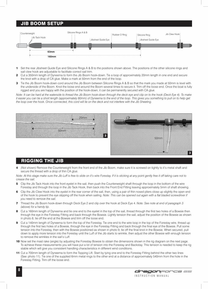
1 Set the rear Jibsheet Guide Eye and Silicone Rings A & B to the positions shown above. The positions of the other silicone rings and sail clew hook are adjustable to facilitate correct sail trim.2 Cut a 350mm length of Dyneema to form the Jib Boom hook-down. Tie a loop of approximately 20mm length in one end and secure the knot with a drop of CA glue. Make a mark at 50mm from the end of the loop.
3 Tie the Jib Boom hook-down cord around the Jib Boom between Silicone Rings A & B so that the mark you made at 50mm is level with the underside of the Boom. Knot the loose end around the Boom several times to secure it. Trim off the loose end. Once the boat is fully rigged and you are happy with the position of the hook-down, it can be permanently secured with CA glue.
Note: It can be hard at the waterside to thread the Jib Boom hook-down through the deck eye and clip on to the hook (Deck Eye 4). To make it easier you can tie a short length (approximately 80mm) of Dyneema to the end of the loop. This gives you something to pull on to help get the loop over the hook. Once connected, this cord will lie on the deck and not interfere with the Jib Sheeting.
JIB BOOM SETUP
3
2
50mm
20mm
50mm
RIGGING THE JIB4 (Not shown) Remove the Counterweight from the front end of the Jib Boom, make sure it is screwed on tightly to it’s metal shaft and secure the thread with a drop of thin CA glue.
Note: At this stage make sure the Jib Luff is free to slide on it’s wire Forestay. If it is sticking at any point gently free it off taking care not to crease the sail.
5 Clip the Jib Tack Hook into the front eyelet in the sail, then push the Counterweight shaft through the loop in the bottom of the wire Forestay and through the loop in the Jib Tack Hook, then back into the Front End Fitting leaving approximately 5mm of shaft showing.
6 Clip the Jib Clew Hook into the eyelet in the rear corner of the sail, then, using a pair of thin nosed pliers close up slightly the open end of the hook to prevent the eye slipping off the hook when sailing. Note: This can be opened out again with a flat bladed screwdriver if you need to remove the sail.
7 Thread the Jib Boom hook-down through Deck Eye 2 and clip over the hook at Deck Eye 4. Note: See note at end of paragraph 3 (above) for a handy tip.
8 Cut a 160mm length of Dyneema and tie one end to the eyelet in the top of the sail, thread through the first two holes of a Bowsie then through the eye in the Forestay Fitting and back through the Bowsie. Lightly tension the sail, adjust the position of the Bowsie as shown in photo 8, tie off the end at the Bowsie and trim off the loose end.
9 Cut a 140mm length of Dyneema to form the top of the Forestay. Tie one end to the wire loop in the top of the Forestay wire, thread up through the first two holes of a Bowsie, through the eye in the Forestay Fitting and back through the final eye of the Bowsie. Pull some tension into the Forestay, then with the Bowsie positioned as shown in photo 9, tie off the final knot in the Bowsie. When secured, pull down to apply more tension into the Forestay until the Luff of the Jib starts to wrinkle, then adjust the other Bowsie with enough tension to remove the wrinkles in the sail’s Luff.
10 Now set the mast rake (angle) by adjusting the Forestay Bowsie to obtain the dimensions shown in the rig diagram on the next page. To achieve these measurements you will have put a lot of tension into the Forestay and Backstay. This tension is needed to keep the rig stable which will give you consistent handling characteristics in different wind conditions.
11 Cut a 700mm length of Dyneema to form the Topping Lift. Start by tying one end to the Forestay Fitting behind the other two lines (See photo 11). Tie one of the supplied 6mm metal rings to the other end at a distance of approximately 540mm from the hole in the Forestay Fitting. Trim off the loose end.
63mm
160mm
Counterweight Silicone Rings A & B
Jib Tack HookJibsheet Guide Eye
Jib Clew Hook
Jibsheet Guide Eye
Rubber O Ring Silicone Ring
I N S T R U C T I O N M A N U A L
9
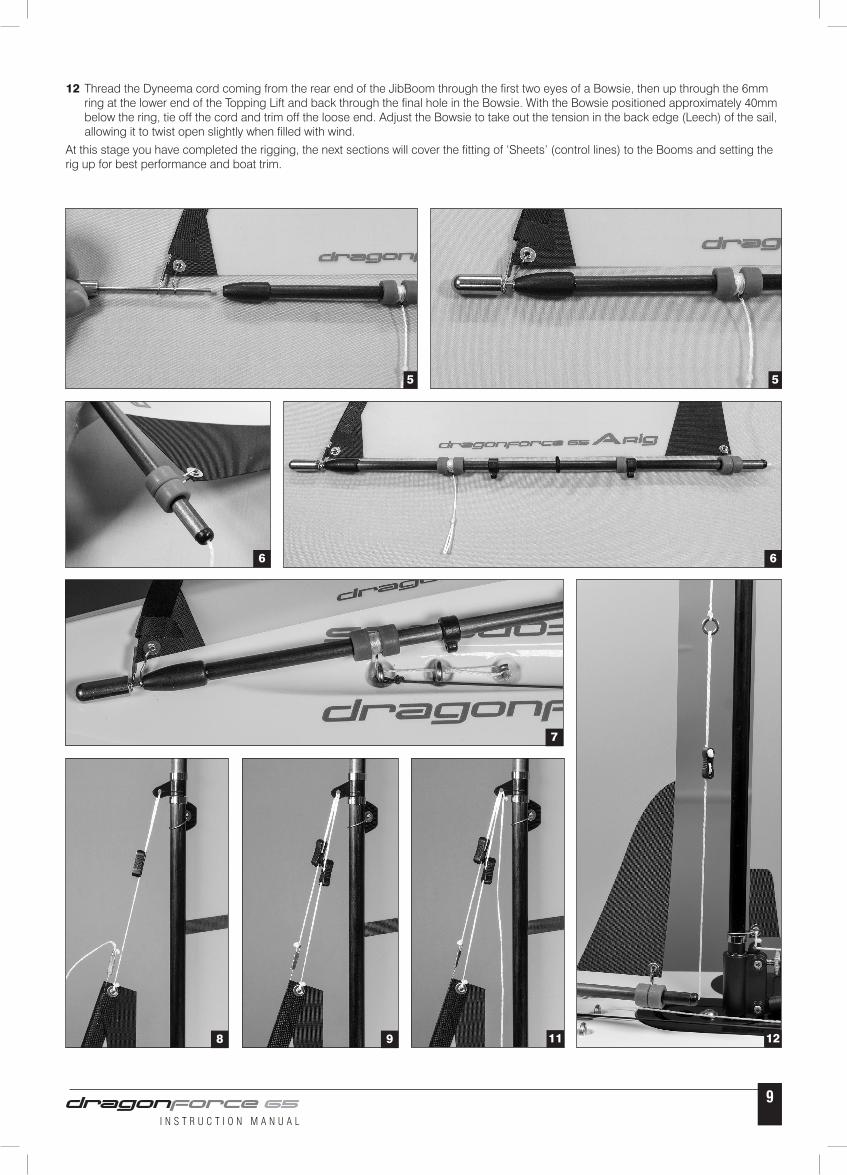
12 Thread the Dyneema cord coming from the rear end of the JibBoom through the first two eyes of a Bowsie, then up through the 6mm ring at the lower end of the Topping Lift and back through the final hole in the Bowsie. With the Bowsie positioned approximately 40mm below the ring, tie off the cord and trim off the loose end. Adjust the Bowsie to take out the tension in the back edge (Leech) of the sail, allowing it to twist open slightly when filled with wind.
At this stage you have completed the rigging, the next sections will cover the fitting of ‘Sheets’ (control lines) to the Booms and setting the rig up for best performance and boat trim.
5
6
5
6
7
8 9 11 12
I N S T R U C T I O N M A N U A L
10
BA
CK
STA
Y LE
NG
TH =
930mm
MA
ST
RA
KE
= 7
50m
m
Mea
sure
men
t tak
en fr
om b
ack
edge
of r
ubbe
r bum
per
Mea
sure
men
t tak
en fr
om c
entre
of t
he h
ole
in th
e Fo
rest
ay F
ittin
g
Measurem
ent taken from centre of the hole in the B
ackstay Crane
Measurem
ent taken from the top of the B
ackstay Hook
I N S T R U C T I O N M A N U A L
11
POWERING UP THE BOATIf you’ve bought the ‘Ready To Race’ version (8815) of the boat you will have the Joysway Transmitter and Receiver. The transmitter (Tx) and Receiver (Rx) will already be ‘bound’ and full operating instructions for this radio set are supplied.
If you are using your own Tx/Rx equipment we will assume you will be familiar with all it’s functions and the following guide covers the setup of the boat only.
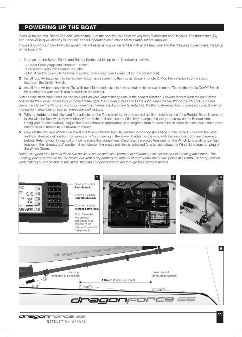
1 Connect up the Servo, Winch and Battery Switch cables up to the Receiver as follows:
- Rudder Servo plugs into Channel 1 socket. - Sail Winch plugs into Channel 3 socket - On/Off Switch plugs into Channel 5 socket (check your own Tx manual for this connection)
2 Install four, AA batteries into the Battery Holder and secure into the tray as shown in photo 2. Plug the batteries into the spare lead from the On/Off Switch.
3 Install four, AA batteries into the Tx. With both Tx control sticks in their central positions switch on the Tx and the boat’s On/Off Switch by pushing the wire switch arm forwards in the cockpit.
Note: At this stage check that the control sticks on your Transmitter operate in the correct direction. Looking forward from the back of the boat when the rudder control stick is moved to the right, the Rudder should turn to the right. When the Sail Winch control stick is moved down, the clip on the Winch Line should move to its furthest back position (sheeted in). If either of these actions is reversed, consult your TX manual for instructions on how to reverse the stick actions.
4 With the rudder control stick and fine adjuster on the Transmitter set in their central position, check to see if the Rudder Blade is centred in line with the Keel when viewed directly from behind. If not, use the Allen Key to adjust the top grub screw on the Rudder Arm. Using your Tx (see manual), adjust the rudder throw to approximately 40 degrees from the centreline in either direction when the rudder control stick is moved to it’s maximum throws.
5 Now set the required Winch Line travel of 115mm between the fully sheeted in position (for sailing ‘close hauled’ - close to the wind) and fully sheeted out position (for sailing on a ‘run’ - sailing in the same direction as the wind with the sails fully out) (see diagram 5 below). Refer to your Tx manual on how to make this adjustment. Check that the elastic tensioner on the Winch Line is still under light tension in the ‘sheeted out’ position, if not, shorten the elastic until this is achieved (this tension stops the Winch Line from jumping off the Winch Drum).
Note: It’s a good idea to mark these two positions on the deck as a permanent reference points for consistent sheeting adjustment. The sheeting points shown are not too critical but what is important is the amount of travel between the two points of 115mm. On computerised Transmitters you will be able to adjust the sheeting end points individually through their software menus.
5
115mm Winch Line travel
Close Hauled (sheeted in position)
Running (sheeted out position)
1 2 4
Channel 5 socket:Switch lead.
Channel 3 socket:Sail Winch lead.
Channel 1 socket:Rudder Servo lead.
Note: The darker wire on each lead needs to be adjacent to the edge of the receiver. (see photo 2)
I N S T R U C T I O N M A N U A L
12
SHEETING SETUP1 For initial sheet setup of both the Jib and Mainsheet, pull the winchline in to its close-hauled (sheeted fully in) position and don’t move it until both sheets are fully installed.
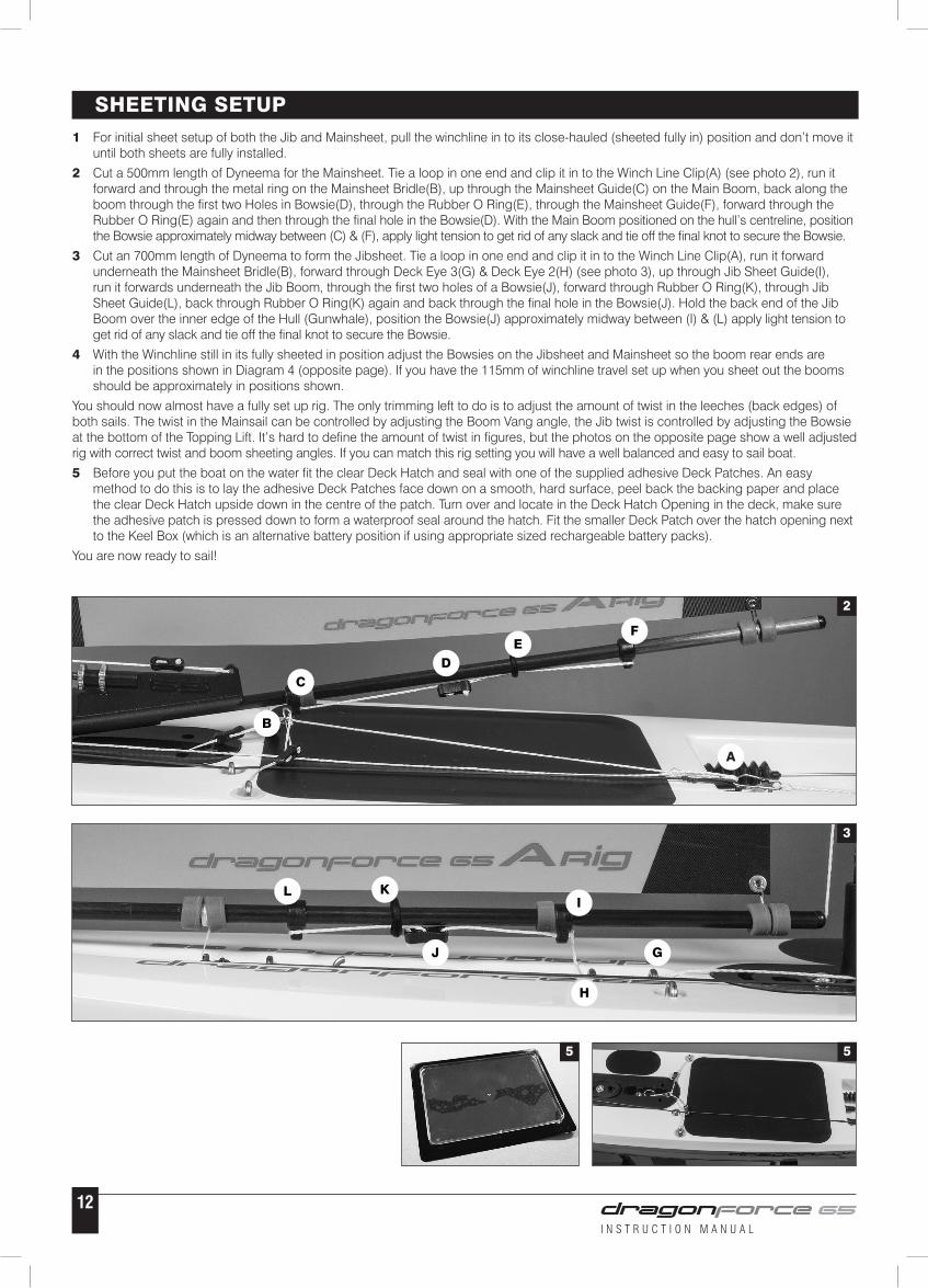
2 Cut a 500mm length of Dyneema for the Mainsheet. Tie a loop in one end and clip it in to the Winch Line Clip(A) (see photo 2), run it forward and through the metal ring on the Mainsheet Bridle(B), up through the Mainsheet Guide(C) on the Main Boom, back along the boom through the first two Holes in Bowsie(D), through the Rubber O Ring(E), through the Mainsheet Guide(F), forward through the Rubber O Ring(E) again and then through the final hole in the Bowsie(D). With the Main Boom positioned on the hull’s centreline, position the Bowsie approximately midway between (C) & (F), apply light tension to get rid of any slack and tie off the final knot to secure the Bowsie.
3 Cut an 700mm length of Dyneema to form the Jibsheet. Tie a loop in one end and clip it in to the Winch Line Clip(A), run it forward underneath the Mainsheet Bridle(B), forward through Deck Eye 3(G) & Deck Eye 2(H) (see photo 3), up through Jib Sheet Guide(I), run it forwards underneath the Jib Boom, through the first two holes of a Bowsie(J), forward through Rubber O Ring(K), through Jib Sheet Guide(L), back through Rubber O Ring(K) again and back through the final hole in the Bowsie(J). Hold the back end of the Jib Boom over the inner edge of the Hull (Gunwhale), position the Bowsie(J) approximately midway between (I) & (L) apply light tension to get rid of any slack and tie off the final knot to secure the Bowsie.
4 With the Winchline still in its fully sheeted in position adjust the Bowsies on the Jibsheet and Mainsheet so the boom rear ends are in the positions shown in Diagram 4 (opposite page). If you have the 115mm of winchline travel set up when you sheet out the booms should be approximately in positions shown.
You should now almost have a fully set up rig. The only trimming left to do is to adjust the amount of twist in the leeches (back edges) of both sails. The twist in the Mainsail can be controlled by adjusting the Boom Vang angle, the Jib twist is controlled by adjusting the Bowsie at the bottom of the Topping Lift. It’s hard to define the amount of twist in figures, but the photos on the opposite page show a well adjusted rig with correct twist and boom sheeting angles. If you can match this rig setting you will have a well balanced and easy to sail boat.
5 Before you put the boat on the water fit the clear Deck Hatch and seal with one of the supplied adhesive Deck Patches. An easy method to do this is to lay the adhesive Deck Patches face down on a smooth, hard surface, peel back the backing paper and place the clear Deck Hatch upside down in the centre of the patch. Turn over and locate in the Deck Hatch Opening in the deck, make sure the adhesive patch is pressed down to form a waterproof seal around the hatch. Fit the smaller Deck Patch over the hatch opening next to the Keel Box (which is an alternative battery position if using appropriate sized rechargeable battery packs).
You are now ready to sail!
5 5
2
3
A
B
CD
EF
G
H
I
J
KL
I N S T R U C T I O N M A N U A L
13
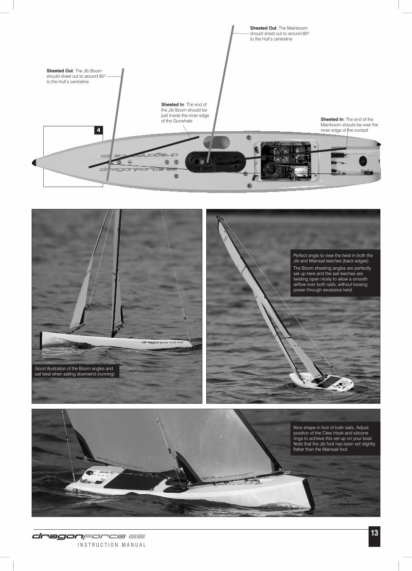
4
Sheeted In: The end of the Mainboom should be over the inner edge of the cockpit
Sheeted In: The end of the Jib Boom should be just inside the inner edge of the Gunwhale
Sheeted Out: The Mainboom should sheet out to around 80º to the Hull’s centreline
Sheeted Out: The Jib Boom should sheet out to around 85º to the Hull’s centreline
Good illustration of the Boom angles and sail twist when sailing downwind (running)
Perfect angle to view the twist in both the Jib and Mainsail leeches (back edges).
The Boom sheeting angles are perfectly set up here and the sail leeches are twisting open nicely to allow a smooth airflow over both sails, without loosing power through excessive twist.
Nice shape in foot of both sails. Adjust position of the Clew Hook and silicone rings to achieve this set up on your boat. Note that the Jib foot has been set slightly flatter than the Mainsail foot.
I N S T R U C T I O N M A N U A L
14
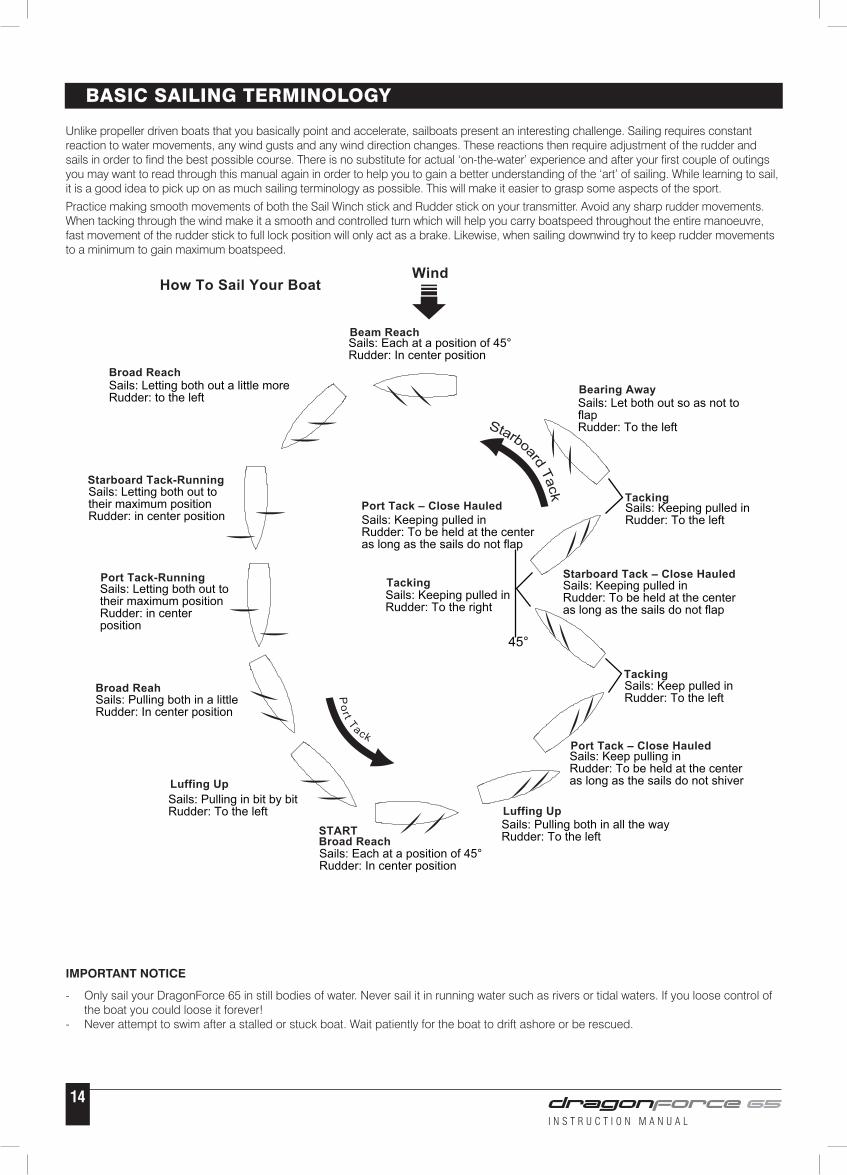
Unlike propeller driven boats that you basically point and accelerate, sailboats present an interesting challenge. Sailing requires constant reaction to water movements, any wind gusts and any wind direction changes. These reactions then require adjustment of the rudder and sails in order to find the best possible course. There is no substitute for actual ‘on-the-water’ experience and after your first couple of outings you may want to read through this manual again in order to help you to gain a better understanding of the ‘art’ of sailing. While learning to sail, it is a good idea to pick up on as much sailing terminology as possible. This will make it easier to grasp some aspects of the sport.
Practice making smooth movements of both the Sail Winch stick and Rudder stick on your transmitter. Avoid any sharp rudder movements. When tacking through the wind make it a smooth and controlled turn which will help you carry boatspeed throughout the entire manoeuvre, fast movement of the rudder stick to full lock position will only act as a brake. Likewise, when sailing downwind try to keep rudder movements to a minimum to gain maximum boatspeed.
BASIC SAILING TERMINOLOGY
IMPORTANT NOTICE
- Only sail your DragonForce 65 in still bodies of water. Never sail it in running water such as rivers or tidal waters. If you loose control of the boat you could loose it forever!- Never attempt to swim after a stalled or stuck boat. Wait patiently for the boat to drift ashore or be rescued.
How To Sail Your Boat
Sails: Each at a position of 45°Rudder: In center position
Wind
Beam Reach
Sails: Letting both out a little moreRudder: to the left
Sails: Letting both out to their maximum positionRudder: in center position
Sails: Letting both out to their maximum positionRudder: in center position
Sails: Pulling both in a littleRudder: In center position
Sails: Pulling in bit by bitRudder: To the left
Sails: Each at a position of 45°Rudder: In center position
Sails: Pulling both in all the wayRudder: To the left
Sails: Keep pulling inRudder: To be held at the center as long as the sails do not shiver
Sails: Keep pulled inRudder: To the left
Sails: Keeping pulled inRudder: To the right
Sails: Keeping pulled inRudder: To be held at the centeras long as the sails do not flap
Sails: Keeping pulled inRudder: To be held at the centeras long as the sails do not flap
Sails: Keeping pulled inRudder: To the left
Sails: Let both out so as not to flapRudder: To the left
Broad Reach
Starboard Tack-Running
Port Tack-Running
Broad Reah
Luffing Up
STARTBroad Reach
Luffing Up
Port Tack – Close Hauled
Tacking
TackingStarboard Tack – Close Hauled
TackingPort Tack – Close Hauled
Bearing Away
45°
I N S T R U C T I O N M A N U A L
15
Item No Item Name
880502 Standard keel with screws880503 Rudder880504 550g standard ballast880510 Sheeting pulley block880511 1m Sheeting elastic880519 Winch line rubber cap (pk2)881210 Bowsie(PK10)880532 Deck eyes (pk10)880565 DF65 V5 Pear shaped mainsail luff rings (pk10) 880534 (Short) 240mm Keel with screws880535 Aluminum alloy rudder arm set880536 Rubber bung (PK4)880542 Plastic molded boat stand880545 2014 version sail winch servo set 880551 Metal Protection ring for Mast (PK10)880552 Battery box for receiver880554 Mast fitting tube880559 Cord attachment clip (PK2)880570 DF65 V5 Siliconee rubber “O” rings(PK10)881501 Servo Tray 881502 Fin Box & Mast Fitting881503 Front Bumper V6(Pk 2)881504 New digital metal gear Rudder Servo 881155 J4C05 Transmitter & J5C01R Receiver set881506 J5C01R Receiver881507 5m White Dyneema881508 A+ Sail Set. 50 micron Mylar, printed.881509 A Sail Set. 50 micron Mylar, printed881510 B Sail Set. 50 micron Mylar, printed881511 C Sail Set. 50 micron Mylar, printed881512 A+ Masthead Plug & Carbon Backstay Crane881513 A, B & C Masthead Plug & Carbon Backstay Crane881514 Stainless steel Sail Clew Hook (Pk 10)881515 Stainless steel Jib Tack Hook (Pk 10)881516 Rudder Pushrod with Bellows V6881517 A+ Mast Set881518 A Mast Set881519 B Mast Set881520 C Mast Set881521 V6 Jib boom counterbalance weight+Shaft(PK4)881522 V6 Jib Boom Set (suitable for all rigs)881523 A+ Main Boom Set881524 Main Boom Set (suitable for A, B & C rigs)881525 V6 Version Hull - painted white.881526 Metal Rings for Mainsheet Bridle (Pk 10)881527 V6 Deck & Battery Patches (Pk4)881528 V6 Transparent Hatch(PK2)881529 V6 Switch rod w/ rubber bellow & switch connector set881530 V6 Complete A+ Rig Assembly (No Sails)881531 V6 Complete A Rig Assembly (No Sails)881532 V6 Complete B Rig Assembly (No Sails)881533 V6 Complete C Rig Assembly (No Sails)881534 Mainsheet Bridle Keelbolt Fitting Plate (Pk 2)881535 V6 Hull Decal Sticker Set881536 Boom End Rear Plug (Pk 10)881537 Boom Band Eye for 5mm Boom Tube (Pk 10)881538 Moulded black colour siliconee tube (Pk20)881539 Moulded mast base collar (PK4)881540 Forestay fiting (PK4)881541 DF65 Bearing(PK4)881542 Switch Rod with Rubber Bellows (compatible with V3-V5 hull to install 8815 servo tray)”
MAINTENANCE SPARE PARTS LIST
If properly rigged and maintained the DragonForce65 will be a very ‘dry’ boat. This is a very good thing as water and electrics are not the best of friends!
There are some essential steps you need to take to keep your boat working as it should, these are:
- The bearings in the top and bottom of the Gooseneck should be washed in clean, fresh water after every outing if you sail in saltwater.
- Regularily lubricate the bearings with bearing lube or any similar product.
- Wash the whole boat and rig with clean, fresh water after every outing if you sail in saltwater.
- Open the Hatch Cover and allow the inside of the boat to completely dry out after sailing. Do not store the boat with either water or condensation inside the hull, it will lead to electrical failure through corrosion or ‘black wire’ failure.
- Dyneema cord can shrink in certain conditions. So check often that all your rig settings remain correct.
- Handle and store the Sails with great care. Don’t leave them flapping whilst your boat sits on its stand, lay the boat down on a soft surface with the rig downwind of the hull. When not in use keep the rigs in a rigid rig box or fairly stiff rig bag. Look after your rigs - they are your boat’s engine!
ALTERNATIVE BATTERY LOCATION
If you prefer to use rechargeable battery packs, such as LiFe (Lithium Ferrite) packs or NiCad (Nickel Cadmium) packs, these can be attached to the side of the Keel Box inside the Hull and accessed via the deck opening adjacent to the Mast. The battery packs can be secured by means of self-adhesive Velcro. To locate the battery here you will also need a short extension lead for the battery cable.
The advantage of doing this is the greater convenience of only having to lift the smaller deck patch to gain access to change your battery. It also helps the trim of the boat in lighter winds by moving the battery weight further forward.
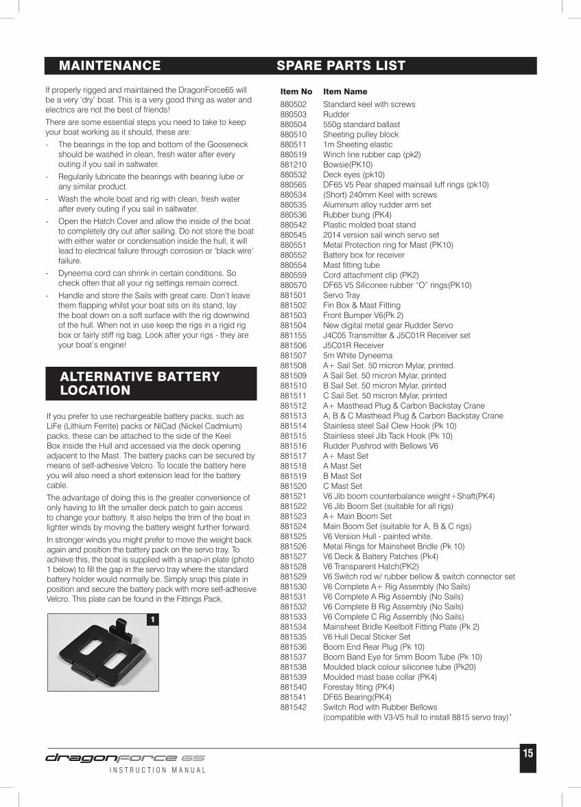
In stronger winds you might prefer to move the weight back again and position the battery pack on the servo tray. To achieve this, the boat is supplied with a snap-in plate (photo 1 below) to fill the gap in the servo tray where the standard battery holder would normally be. Simply snap this plate in position and secure the battery pack with more self-adhesive Velcro. This plate can be found in the Fittings Pack.
1

For more information about the boat and the DragonForce 65 Racing Class please visit
www.dfracing.world
Please note that this product cannot be disposed of in general household waste as it contains electrical components. Under the Waste Electronic and Electrical Equipment Directive (WEEE), this product should only be disposed of at a correct re-cycling facility or by returning it to the shop it was purchased from. Please contact your local authority for details of your local re-cycling centre.
This product complies with the essential requirements of all relevant EU Directives. A copy of the Declaration of Conformity can be obtained from the following website www.joysway-hobby.com