Embed Size (px)
Citation preview

PERFORMANCEMADE
SMARTER
Product Manual 7501Field mounted HART temperature transmitter
TEMPER ATURE | I .S . INTERFACES | COMMUNIC ATION INTERFACES | MULTIFUNC TIONAL | ISOL ATION | D ISPL AY
No. 7501V101-UKFrom serial no. : 150810001

6 Product Pillarsto meet your every need
With our innovative, patented technologies, we make signal conditioning smarter and simpler. Our portfolio is composed of six product areas, where we offer a wide range of analog and digital devices covering over a thousand applications in industrial and factory automation. All our products comply with or surpass the highest industry standards, ensuring reliability in even the harshest of environments and have a 5-year warranty for greater peace of mind.
Individually outstanding, unrivalled in combination
Our range of temperature transmitters and sensors provides the highest level of signal integrity from the measurement point to your control system. You can convert industrial process temperature signals to analog, bus or digital communications using a highly reliable point-to-point solution with a fast response time, automatic self-calibration, sensor error detection, low drift, and top EMC performance in any environment.
Our unique range of single devices covering multiple applications is easily deployable as your site standard. Having one variant that applies to a broad range of applications can reduce your installation time and training, and greatly simplify spare parts management at your facilities. Our devices are designed for long-term signal accuracy, low power consumption, immunity to electrical noise and simple programming.
We provide inexpensive, easy-to-use, future-ready communication interfaces that can access your PR installed base of products. The detachable 4501 Local Operator Interface (LOI) allows for local monitoring of process values, device configuration, error detection and signal simulation. The next generation, our 4511 Remote Operator Interface (ROI) does all that and more, adding remote digital communications via Modbus/RTU, while the analog output signals are still available for redundancy.With the 4511 you can further expand connectivity with a PR gateway, which connects via industrial Ethernet, wirelessly through a Wi-Fi router or directly with the devices using our Portable Plant Supervisor (PPS) application. The PPS app is available for iOS, Android and Windows.
Our display range is characterized by its flexibility and stability. The devices meet nearly every demand for display readout of process signals, and have universal input and power supply capabilities. They provide a real-time measurement of your process value no matter the industry, and are engineered to provide a user-friendly and reliable relay of information, even in demanding environments.
We deliver the safest signals by validating our products against the toughest safety standards. Through our commitment to innovation, we have made pioneering achievements in developing I.S. interfaces with SIL 2 Full Assessment that are both efficient and cost-effective. Our comprehensive range of analog and digital intrinsically safe isolation barriers offers multifunctional inputs and outputs, making PR an easy-to-implement site standard. Our backplanes further simplify large installations and provide seamless integration to standard DCS systems.
Our compact, fast, high-quality 6 mm isolators are based on microprocessor technology to provide exceptional performance and EMC-immunity for dedicated applications at a very low total cost of ownership. They can be stacked both vertically and horizontally with no air gap separation between units required.
7501V101-UK 3
Field mounted HART temperature transmitter
7501
Table of contentsWarning . . . . . . . . . . . . . . . . . . . . . . . . . . . . . . . . . . . . . . . . . . . . . . . . . . . . . . . . . . . . . . . . . . . . . . . . . . . . . . . . . . . . . . . . . . . . . . . . 4Applications . . . . . . . . . . . . . . . . . . . . . . . . . . . . . . . . . . . . . . . . . . . . . . . . . . . . . . . . . . . . . . . . . . . . . . . . . . . . . . . . . . . . . . . . . . . . 5Order . . . . . . . . . . . . . . . . . . . . . . . . . . . . . . . . . . . . . . . . . . . . . . . . . . . . . . . . . . . . . . . . . . . . . . . . . . . . . . . . . . . . . . . . . . . . . . . . . . . 6Accessories . . . . . . . . . . . . . . . . . . . . . . . . . . . . . . . . . . . . . . . . . . . . . . . . . . . . . . . . . . . . . . . . . . . . . . . . . . . . . . . . . . . . . . . . . . . . . 6Technical data . . . . . . . . . . . . . . . . . . . . . . . . . . . . . . . . . . . . . . . . . . . . . . . . . . . . . . . . . . . . . . . . . . . . . . . . . . . . . . . . . . . . . . . . . . 6Block diagram . . . . . . . . . . . . . . . . . . . . . . . . . . . . . . . . . . . . . . . . . . . . . . . . . . . . . . . . . . . . . . . . . . . . . . . . . . . . . . . . . . . . . . . . . . 9Marking. . . . . . . . . . . . . . . . . . . . . . . . . . . . . . . . . . . . . . . . . . . . . . . . . . . . . . . . . . . . . . . . . . . . . . . . . . . . . . . . . . . . . . . . . . . . . . . . . 9Protection degree . . . . . . . . . . . . . . . . . . . . . . . . . . . . . . . . . . . . . . . . . . . . . . . . . . . . . . . . . . . . . . . . . . . . . . . . . . . . . . . . . . . . . . . 14Assembly and disassembly . . . . . . . . . . . . . . . . . . . . . . . . . . . . . . . . . . . . . . . . . . . . . . . . . . . . . . . . . . . . . . . . . . . . . . . . . . . . . . 15Connections . . . . . . . . . . . . . . . . . . . . . . . . . . . . . . . . . . . . . . . . . . . . . . . . . . . . . . . . . . . . . . . . . . . . . . . . . . . . . . . . . . . . . . . . . . . . 17Optical buttons. . . . . . . . . . . . . . . . . . . . . . . . . . . . . . . . . . . . . . . . . . . . . . . . . . . . . . . . . . . . . . . . . . . . . . . . . . . . . . . . . . . . . . . . . . 18Operating the optical buttons . . . . . . . . . . . . . . . . . . . . . . . . . . . . . . . . . . . . . . . . . . . . . . . . . . . . . . . . . . . . . . . . . . . . . . . . . . . . 18Display . . . . . . . . . . . . . . . . . . . . . . . . . . . . . . . . . . . . . . . . . . . . . . . . . . . . . . . . . . . . . . . . . . . . . . . . . . . . . . . . . . . . . . . . . . . . . . . . . 18Device and sensor status indication . . . . . . . . . . . . . . . . . . . . . . . . . . . . . . . . . . . . . . . . . . . . . . . . . . . . . . . . . . . . . . . . . . . . . . 21Display menu . . . . . . . . . . . . . . . . . . . . . . . . . . . . . . . . . . . . . . . . . . . . . . . . . . . . . . . . . . . . . . . . . . . . . . . . . . . . . . . . . . . . . . . . . . . 22
Display . . . . . . . . . . . . . . . . . . . . . . . . . . . . . . . . . . . . . . . . . . . . . . . . . . . . . . . . . . . . . . . . . . . . . . . . . . . . . . . . . . . . . . . . . . . . . . 25Tags. . . . . . . . . . . . . . . . . . . . . . . . . . . . . . . . . . . . . . . . . . . . . . . . . . . . . . . . . . . . . . . . . . . . . . . . . . . . . . . . . . . . . . . . . . . . . . . . . 25Calibration . . . . . . . . . . . . . . . . . . . . . . . . . . . . . . . . . . . . . . . . . . . . . . . . . . . . . . . . . . . . . . . . . . . . . . . . . . . . . . . . . . . . . . . . . . . 26Simulation . . . . . . . . . . . . . . . . . . . . . . . . . . . . . . . . . . . . . . . . . . . . . . . . . . . . . . . . . . . . . . . . . . . . . . . . . . . . . . . . . . . . . . . . . . . 27Sensor . . . . . . . . . . . . . . . . . . . . . . . . . . . . . . . . . . . . . . . . . . . . . . . . . . . . . . . . . . . . . . . . . . . . . . . . . . . . . . . . . . . . . . . . . . . . . . 28HART. . . . . . . . . . . . . . . . . . . . . . . . . . . . . . . . . . . . . . . . . . . . . . . . . . . . . . . . . . . . . . . . . . . . . . . . . . . . . . . . . . . . . . . . . . . . . . . . 28Password . . . . . . . . . . . . . . . . . . . . . . . . . . . . . . . . . . . . . . . . . . . . . . . . . . . . . . . . . . . . . . . . . . . . . . . . . . . . . . . . . . . . . . . . . . . . 29Language. . . . . . . . . . . . . . . . . . . . . . . . . . . . . . . . . . . . . . . . . . . . . . . . . . . . . . . . . . . . . . . . . . . . . . . . . . . . . . . . . . . . . . . . . . . . 29HART Revision . . . . . . . . . . . . . . . . . . . . . . . . . . . . . . . . . . . . . . . . . . . . . . . . . . . . . . . . . . . . . . . . . . . . . . . . . . . . . . . . . . . . . . . 29
Help text overview . . . . . . . . . . . . . . . . . . . . . . . . . . . . . . . . . . . . . . . . . . . . . . . . . . . . . . . . . . . . . . . . . . . . . . . . . . . . . . . . . . . . . . 30Programming . . . . . . . . . . . . . . . . . . . . . . . . . . . . . . . . . . . . . . . . . . . . . . . . . . . . . . . . . . . . . . . . . . . . . . . . . . . . . . . . . . . . . . . . . . . 34Changing the HART protocol version . . . . . . . . . . . . . . . . . . . . . . . . . . . . . . . . . . . . . . . . . . . . . . . . . . . . . . . . . . . . . . . . . . . . . . 35Retrofit . . . . . . . . . . . . . . . . . . . . . . . . . . . . . . . . . . . . . . . . . . . . . . . . . . . . . . . . . . . . . . . . . . . . . . . . . . . . . . . . . . . . . . . . . . . . . . . . . 37Appendix . . . . . . . . . . . . . . . . . . . . . . . . . . . . . . . . . . . . . . . . . . . . . . . . . . . . . . . . . . . . . . . . . . . . . . . . . . . . . . . . . . . . . . . . . . . . . . . 38
ATEX Installation Drawing . . . . . . . . . . . . . . . . . . . . . . . . . . . . . . . . . . . . . . . . . . . . . . . . . . . . . . . . . . . . . . . . . . . . . . . . . . . . 39IECEx Installation Drawing . . . . . . . . . . . . . . . . . . . . . . . . . . . . . . . . . . . . . . . . . . . . . . . . . . . . . . . . . . . . . . . . . . . . . . . . . . . . 45FM Installation Drawing. . . . . . . . . . . . . . . . . . . . . . . . . . . . . . . . . . . . . . . . . . . . . . . . . . . . . . . . . . . . . . . . . . . . . . . . . . . . . . . 51
Document history . . . . . . . . . . . . . . . . . . . . . . . . . . . . . . . . . . . . . . . . . . . . . . . . . . . . . . . . . . . . . . . . . . . . . . . . . . . . . . . . . . . . . . . 56
4 7501V101-UK
WarningOnly technicians, who are familiar with the technical terms, warnings, and instructions in the manual and who are able to follow these, should connect the device.
Should there be any doubt as to the correct handling of the device, please contact your local distributor or PR electronics A/S.
Mounting and connection of the device should comply with national legislation for mounting of electric materials.
Repair of the device must be done by PR electronics A/S only.
Do not remove the transmitter cover in explosive atmospheres when the circuit is alive.
The transmitter cover must be fully engaged to meet the explosion proof requirements.
If installed under high-vibration conditions, the transmitter may require supplementary support.
For installation in hazardous area the corresponding installation drawing must be followed in detail.
Take care not to generate mechanical sparking when accessing the instrument and peripheral devices in a hazardous location.
6
5
4
3
6
5
4
3
+-
6
5
4
3
+-
+-
+-
+-
21
2
21
1
6
5
4
3
1
2C O M M U N I C AT I O N F O U N D AT I O N
+-
6
5
4
3
7501V101-UK 5
Field mounted HART temperature transmitter 7501
• RTD, TC, Ohm, and bipolar mV input and analog output
• High definition local operator interface (LOI) with 3 optical buttons
• Selectable red or white backlight
• Ex d explosion proof / flame proof
• HART 7 functionality with HART 5 compatibility
High defintion display
• 0, 90, 180, & 270 degree position adjustments.• Monitoring, programming and diagnostics view.• Extensive diagnostics with flashing red or white backlight• Supports 7 languages.
Local operator interface (LOI)
• 3 optical buttons; up, down and enter.• Dynamically adaptive to wear or accumulation of dirt.• Immune to interference from ambient light sources.• Useable with or without gloves.
Configuration
• From the LOI through the PR guided menu.• PReset and HART modem.• HHC, DCS or AMS via HART.
Mounting / installation
• For installation in zone 0, 1, 2 and zone 20, 21, 22, in mines M1 and in Class 1, Division 1 and 2 applications.
• Hardware assessed with SFF value of 69%.• Mounting on 1.5”–2” pipe bracket or on wall / bulkhead.
Application
• Linearized temperature measurement with TC and RTD sensors e.g. Pt100 and Ni100.
• HART communication and 4...20 mA analog PV output for individual, difference or average temperature measurement of up to two RTD or TC input sensors.
• Conversion of linear resistance to a standard analog current signal, e.g from valves or Ohmic level sensors.
• Amplification of bipolar mV signals to standard 4...20 mA current signals.
• Up to 63 transmitters (HART 7) can be connected in a multidrop communication setup.
Technical characteristics
• NAMUR NE21, NE43 and NE89.• HART protocol revision can be changed by user
configuration to either HART 5 or HART 7 protocol.
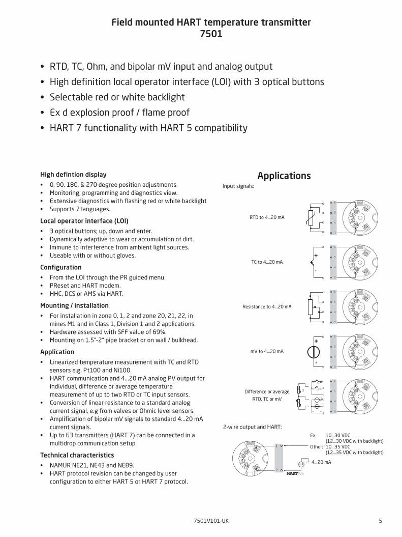
ApplicationsInput signals:
TC to 4...20 mA
Ex: 10...30 VDC (12...30 VDC with backlight)
Other: 10...35 VDC (12...35 VDC with backlight)
4...20 mA
Resistance to 4...20 mA
mV to 4...20 mA
Difference or average
RTD, TC or mV
2-wire output and HART:
RTD to 4...20 mA
6 7501V101-UK
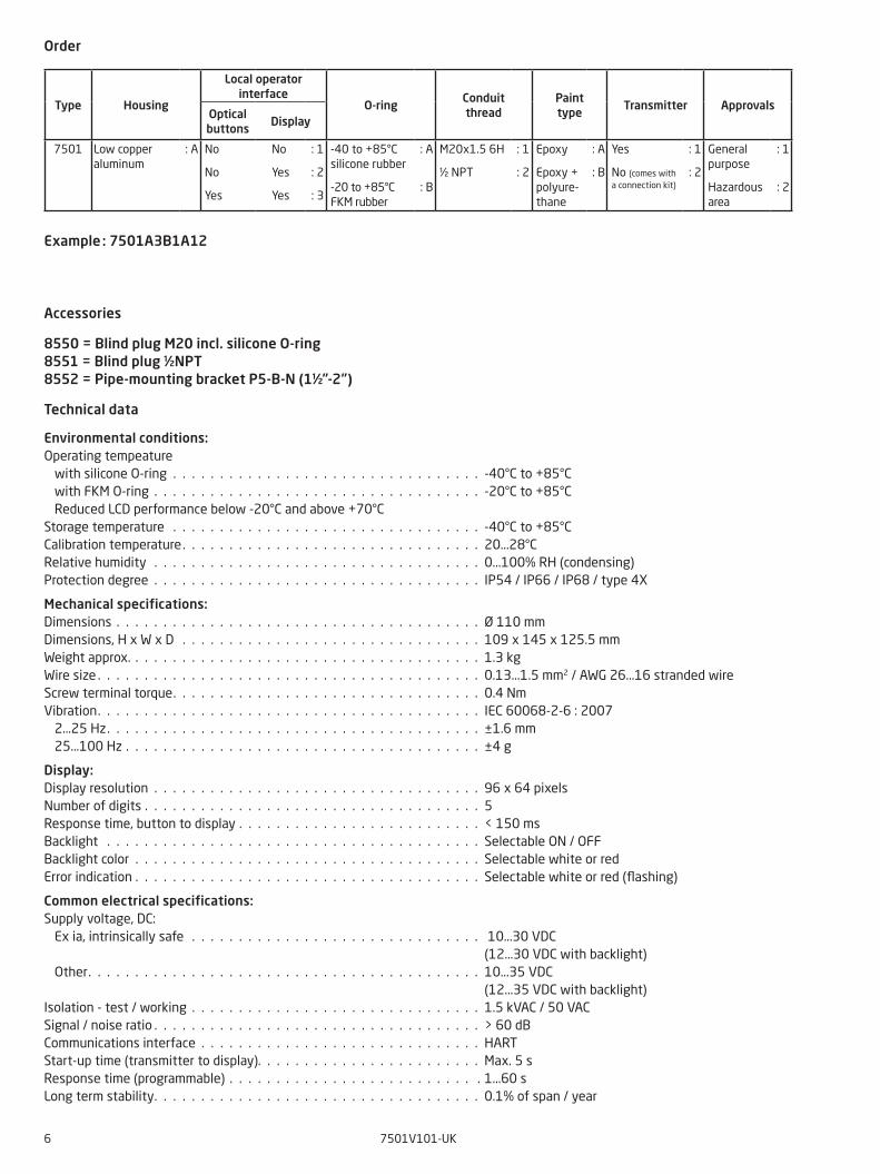
Accessories
8550 = Blind plug M20 incl. silicone O-ring 8551 = Blind plug ½NPT 8552 = Pipe-mounting bracket P5-B-N (1½”-2”)
Technical data
Environmental conditions:Operating tempeature with silicone O-ring . . . . . . . . . . . . . . . . . . . . . . . . . . . . . . . . . -40°C to +85°C with FKM O-ring . . . . . . . . . . . . . . . . . . . . . . . . . . . . . . . . . . . -20°C to +85°C Reduced LCD performance below -20°C and above +70°CStorage temperature . . . . . . . . . . . . . . . . . . . . . . . . . . . . . . . . . -40°C to +85°CCalibration temperature. . . . . . . . . . . . . . . . . . . . . . . . . . . . . . . . 20...28°CRelative humidity . . . . . . . . . . . . . . . . . . . . . . . . . . . . . . . . . . . 0...100% RH (condensing)Protection degree . . . . . . . . . . . . . . . . . . . . . . . . . . . . . . . . . . . IP54 / IP66 / IP68 / type 4X
Mechanical specifications:Dimensions . . . . . . . . . . . . . . . . . . . . . . . . . . . . . . . . . . . . . . . Ø 110 mm Dimensions, H x W x D . . . . . . . . . . . . . . . . . . . . . . . . . . . . . . . . 109 x 145 x 125.5 mm Weight approx. . . . . . . . . . . . . . . . . . . . . . . . . . . . . . . . . . . . . . 1.3 kg Wire size . . . . . . . . . . . . . . . . . . . . . . . . . . . . . . . . . . . . . . . . . 0.13...1.5 mm2 / AWG 26...16 stranded wireScrew terminal torque. . . . . . . . . . . . . . . . . . . . . . . . . . . . . . . . . 0.4 NmVibration. . . . . . . . . . . . . . . . . . . . . . . . . . . . . . . . . . . . . . . . . IEC 60068-2-6 : 2007 2...25 Hz. . . . . . . . . . . . . . . . . . . . . . . . . . . . . . . . . . . . . . . . ±1.6 mm 25...100 Hz . . . . . . . . . . . . . . . . . . . . . . . . . . . . . . . . . . . . . . ±4 g
Display:Display resolution . . . . . . . . . . . . . . . . . . . . . . . . . . . . . . . . . . . 96 x 64 pixelsNumber of digits . . . . . . . . . . . . . . . . . . . . . . . . . . . . . . . . . . . . 5 Response time, button to display . . . . . . . . . . . . . . . . . . . . . . . . . . < 150 ms Backlight . . . . . . . . . . . . . . . . . . . . . . . . . . . . . . . . . . . . . . . . Selectable ON / OFF Backlight color . . . . . . . . . . . . . . . . . . . . . . . . . . . . . . . . . . . . . Selectable white or red Error indication . . . . . . . . . . . . . . . . . . . . . . . . . . . . . . . . . . . . . Selectable white or red (flashing)
Common electrical specifications:Supply voltage, DC: Ex ia, intrinsically safe . . . . . . . . . . . . . . . . . . . . . . . . . . . . . . . 10...30 VDC (12...30 VDC with backlight) Other. . . . . . . . . . . . . . . . . . . . . . . . . . . . . . . . . . . . . . . . . . 10...35 VDC (12...35 VDC with backlight)Isolation - test / working . . . . . . . . . . . . . . . . . . . . . . . . . . . . . . . 1.5 kVAC / 50 VAC Signal / noise ratio . . . . . . . . . . . . . . . . . . . . . . . . . . . . . . . . . . . > 60 dBCommunications interface . . . . . . . . . . . . . . . . . . . . . . . . . . . . . . HART Start-up time (transmitter to display). . . . . . . . . . . . . . . . . . . . . . . . Max. 5 s Response time (programmable) . . . . . . . . . . . . . . . . . . . . . . . . . . . 1...60 s Long term stability. . . . . . . . . . . . . . . . . . . . . . . . . . . . . . . . . . . 0.1% of span / year
Order
Example : 7501A3B1A12
Type Housing
Local operatorinterface
O-ringConduitthread
Painttype
Transmitter ApprovalsOpticalbuttons
Display
7501 Low copper aluminum
: A
No
No
Yes
No
Yes
Yes
: 1
: 2
: 3
-40 to +85°C silicone rubber
-20 to +85°C FKM rubber
: A
: B
M20x1.5 6H
½ NPT
: 1
: 2
Epoxy
Epoxy + polyure-thane
: A
: B
Yes
No (comes with a connection kit)
: 1
: 2
General purpose
Hazardous area
: 1
: 2
7501V101-UK 7
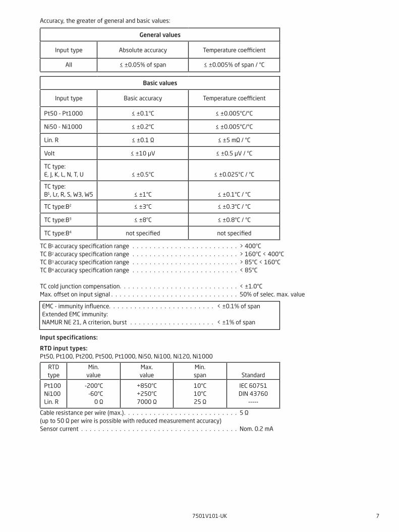
Accuracy, the greater of general and basic values:
TC B1 accuracy specification range . . . . . . . . . . . . . . . . . . . . . . . . . > 400°C TC B2 accuracy specification range . . . . . . . . . . . . . . . . . . . . . . . . . > 160°C < 400°C
TC B3 accuracy specification range . . . . . . . . . . . . . . . . . . . . . . . . . > 85°C < 160°CTC B4 accuracy specification range . . . . . . . . . . . . . . . . . . . . . . . . . < 85°C
TC cold junction compensation. . . . . . . . . . . . . . . . . . . . . . . . . . . . < ±1.0°C Max. offset on input signal . . . . . . . . . . . . . . . . . . . . . . . . . . . . . . 50% of selec. max. value
Input specifications:
RTD input types:Pt50, Pt100, Pt200, Pt500, Pt1000, Ni50, Ni100, Ni120, Ni1000
Cable resistance per wire (max.). . . . . . . . . . . . . . . . . . . . . . . . . . . 5 Ω(up to 50 Ω per wire is possible with reduced measurement accuracy)Sensor current . . . . . . . . . . . . . . . . . . . . . . . . . . . . . . . . . . . . . Nom. 0.2 mA
RTD type
Min. value
Max. value
Min. span
Standard
Pt100Ni100Lin. R
-200°C-60°C
0 Ω
+850°C+250°C7000 Ω
10°C10°C25 Ω
IEC 60751DIN 43760
-----
EMC - immunity influence. . . . . . . . . . . . . . . . . . . . . . . . . < ±0.1% of spanExtended EMC immunity:NAMUR NE 21, A criterion, burst . . . . . . . . . . . . . . . . . . . . < ±1% of span
General values
Input type Absolute accuracy Temperature coefficient
All ≤ ±0.05% of span ≤ ±0.005% of span / °C
Basic values
Input type Basic accuracy Temperature coefficient
Pt50 - Pt1000 ≤ ±0.1°C ≤ ±0.005°C/°C
Ni50 - Ni1000 ≤ ±0.2°C ≤ ±0.005°C/°C
Lin. R ≤ ±0.1 Ω ≤ ±5 mΩ / °C
Volt ≤ ±10 μV ≤ ±0.5 µV / °C
TC type:E, J, K, L, N, T, U
≤ ±0.5°C
≤ ±0.025°C / °C
TC type: B1, Lr, R, S, W3, W5
≤ ±1°C
≤ ±0.1°C / °C
TC type:B2 ≤ ±3°C ≤ ±0.3°C / °C
TC type:B3 ≤ ±8°C ≤ ±0.8°C / °C
TC type:B4 not specified not specified
8 7501V101-UK
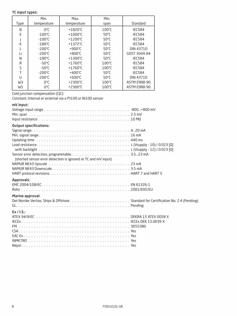
TC input types:
Cold junction compensation (CJC):Constant, internal or external via a Pt100 or Ni100 sensor
mV input:Voltage input range . . . . . . . . . . . . . . . . . . . . . . . . . . . . . . . . . . -800...+800 mV Min. span . . . . . . . . . . . . . . . . . . . . . . . . . . . . . . . . . . . . . . . . 2.5 mV Input resistance . . . . . . . . . . . . . . . . . . . . . . . . . . . . . . . . . . . . 10 MΩ
Output specifications:Signal range. . . . . . . . . . . . . . . . . . . . . . . . . . . . . . . . . . . . . . . 4...20 mA Min. signal range . . . . . . . . . . . . . . . . . . . . . . . . . . . . . . . . . . . . 16 mA Updating time . . . . . . . . . . . . . . . . . . . . . . . . . . . . . . . . . . . . . 440 ms Load resistance. . . . . . . . . . . . . . . . . . . . . . . . . . . . . . . . . . . . . ≤ (Vsupply - 10) / 0.023 [Ω] with backlight . . . . . . . . . . . . . . . . . . . . . . . . . . . . . . . . . . . . ≤ (Vsupply - 12) / 0.023 [Ω] Sensor error detection, programmable . . . . . . . . . . . . . . . . . . . . . . . 3.5...23 mA (shorted sensor error detection is ignored at TC and mV input)NAMUR NE43 Upscale . . . . . . . . . . . . . . . . . . . . . . . . . . . . . . . . 23 mA NAMUR NE43 Downscale. . . . . . . . . . . . . . . . . . . . . . . . . . . . . . . 3.5 mA HART protocol revisions. . . . . . . . . . . . . . . . . . . . . . . . . . . . . . . . HART 7 and HART 5
Approvals:EMC 2004/108/EC . . . . . . . . . . . . . . . . . . . . . . . . . . . . . . . . . . . EN 61326-1Rohs . . . . . . . . . . . . . . . . . . . . . . . . . . . . . . . . . . . . . . . . . . . 2001/695/EU
Marine approval:Det Norske Veritas, Ships & Offshore . . . . . . . . . . . . . . . . . . . . . . . . Standard for Certification No. 2.4 (Pending) GL. . . . . . . . . . . . . . . . . . . . . . . . . . . . . . . . . . . . . . . . . . . . . Pending
Ex / I.S.:ATEX 94/9/EC . . . . . . . . . . . . . . . . . . . . . . . . . . . . . . . . . . . . . DEKRA 15 ATEX 0058 X IECEx . . . . . . . . . . . . . . . . . . . . . . . . . . . . . . . . . . . . . . . . . . . IECEx DEK 15.0039 X FM . . . . . . . . . . . . . . . . . . . . . . . . . . . . . . . . . . . . . . . . . . . . 3055380 CSA . . . . . . . . . . . . . . . . . . . . . . . . . . . . . . . . . . . . . . . . . . . . Yes EAC Ex . . . . . . . . . . . . . . . . . . . . . . . . . . . . . . . . . . . . . . . . . . YesINMETRO . . . . . . . . . . . . . . . . . . . . . . . . . . . . . . . . . . . . . . . . YesNepsi . . . . . . . . . . . . . . . . . . . . . . . . . . . . . . . . . . . . . . . . . . . Yes
Type
Min.temperature
Max.temperature
Min. span
Standard
BEJKLLrNRSTU
W3W5
0°C-100°C-100°C-180°C-200°C-200°C-180°C
-50°C-50°C
-200°C-200°C
0°C0°C
+1820°C+1000°C+1200°C+1372°C+900°C+800°C
+1300°C+1760°C+1760°C+400°C+600°C
+2300°C+2300°C
100°C50°C50°C50°C50°C50°C50°C
100°C100°C50°C50°C
100°C100°C
IEC584IEC584IEC584IEC584
DIN 43710GOST 3044-84
IEC584IEC584IEC584IEC584
DIN 43710ASTM E988-90ASTM E988-90
7501V101-UK 9
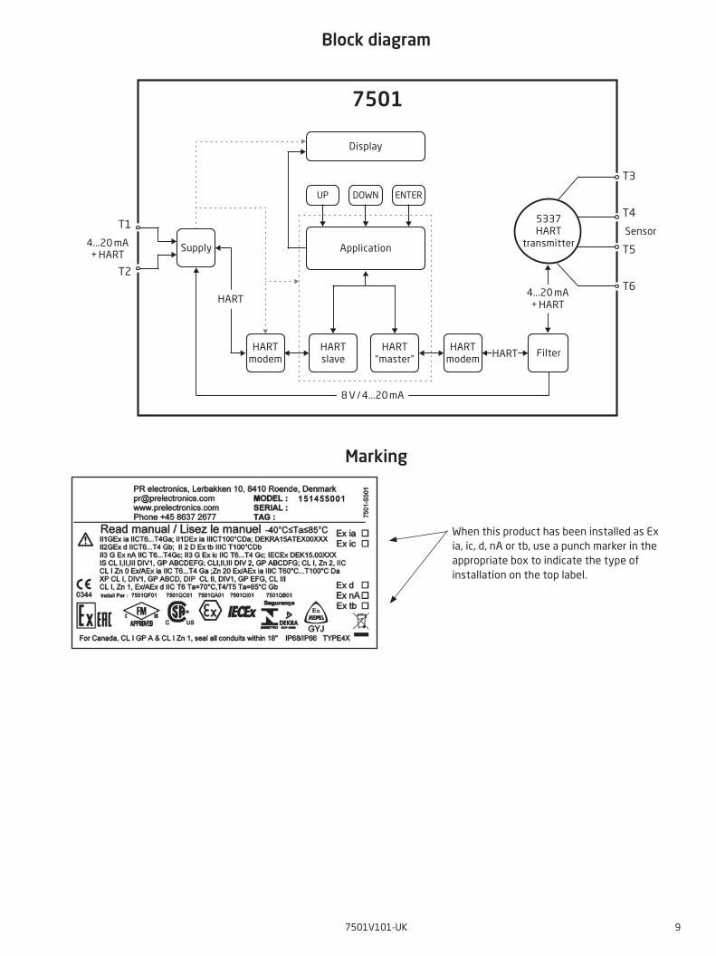
Block diagram
Marking
T1
T2
T3
T4
T5
T6
7501
HART
HART
Application
Sensor
UP DOWN ENTER
HARTslave
HART“master”
HARTmodem
FilterHART
modem
Supply
Display
5337HART
transmitter4...20 mA+ HART
4...20 mA+ HART
8 V / 4...20 mA
When this product has been installed as Ex ia, ic, d, nA or tb, use a punch marker in the appropriate box to indicate the type of installation on the top label.
10 7501V101-UK
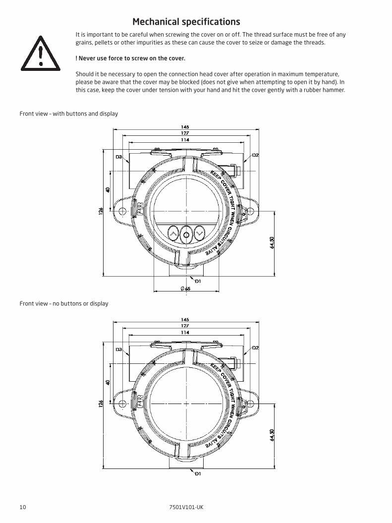
Mechanical specificationsIt is important to be careful when screwing the cover on or off. The thread surface must be free of any grains, pellets or other impurities as these can cause the cover to seize or damage the threads.
! Never use force to screw on the cover.
Should it be necessary to open the connection head cover after operation in maximum temperature, please be aware that the cover may be blocked (does not give when attempting to open it by hand). In this case, keep the cover under tension with your hand and hit the cover gently with a rubber hammer.
Front view – with buttons and display
Front view – no buttons or display
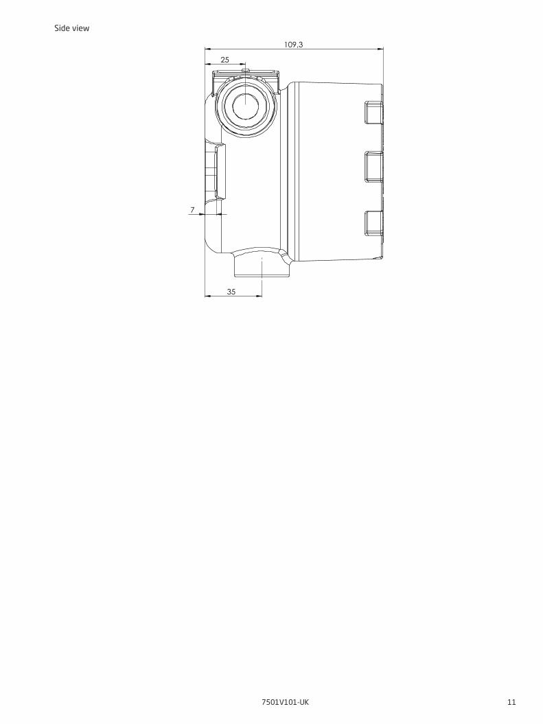
7
109,3
35
25
7501V101-UK 11
Side view
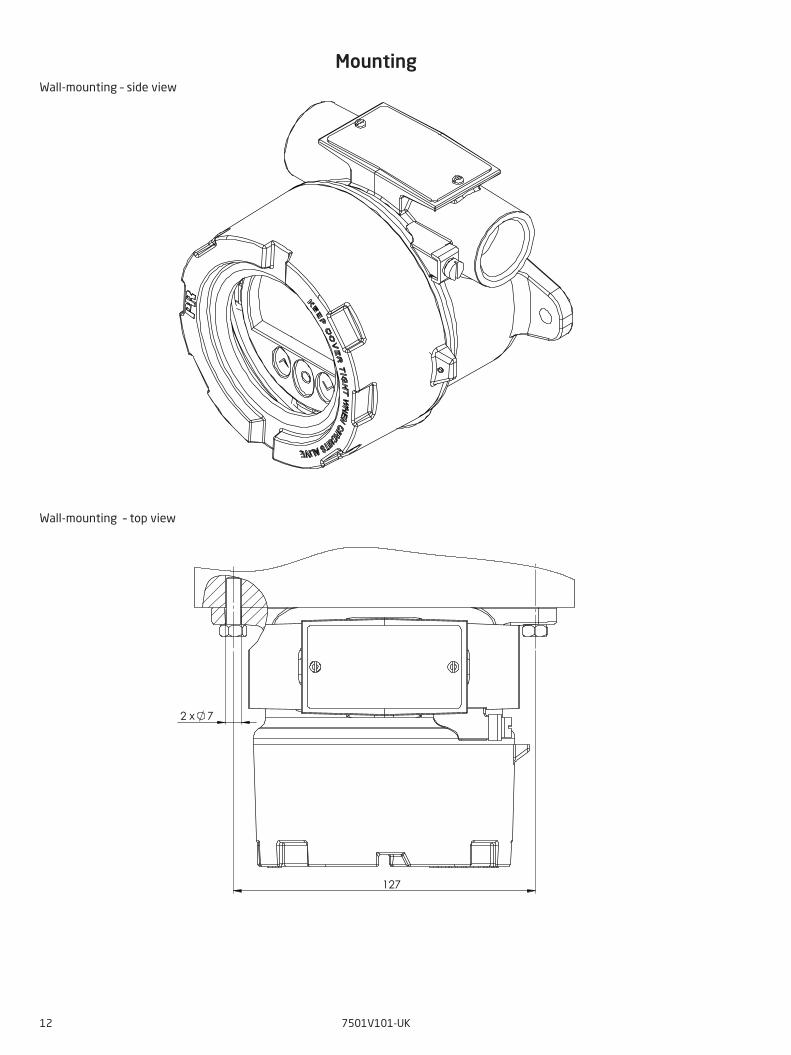
127
2 x 7
12 7501V101-UK
MountingWall-mounting – side view
Wall-mounting – top view
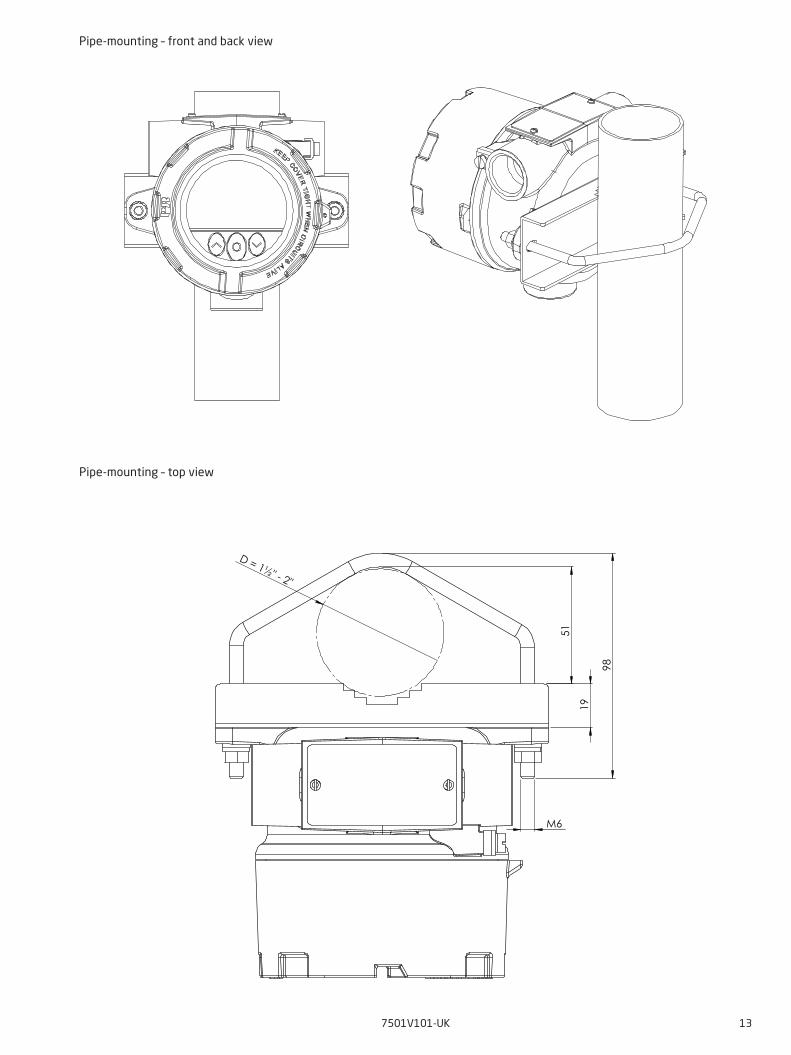
M6
51
19
98
D = 1½" - 2"
7501V101-UK 13
Pipe-mounting – front and back view
Pipe-mounting – top view
14 7501V101-UK
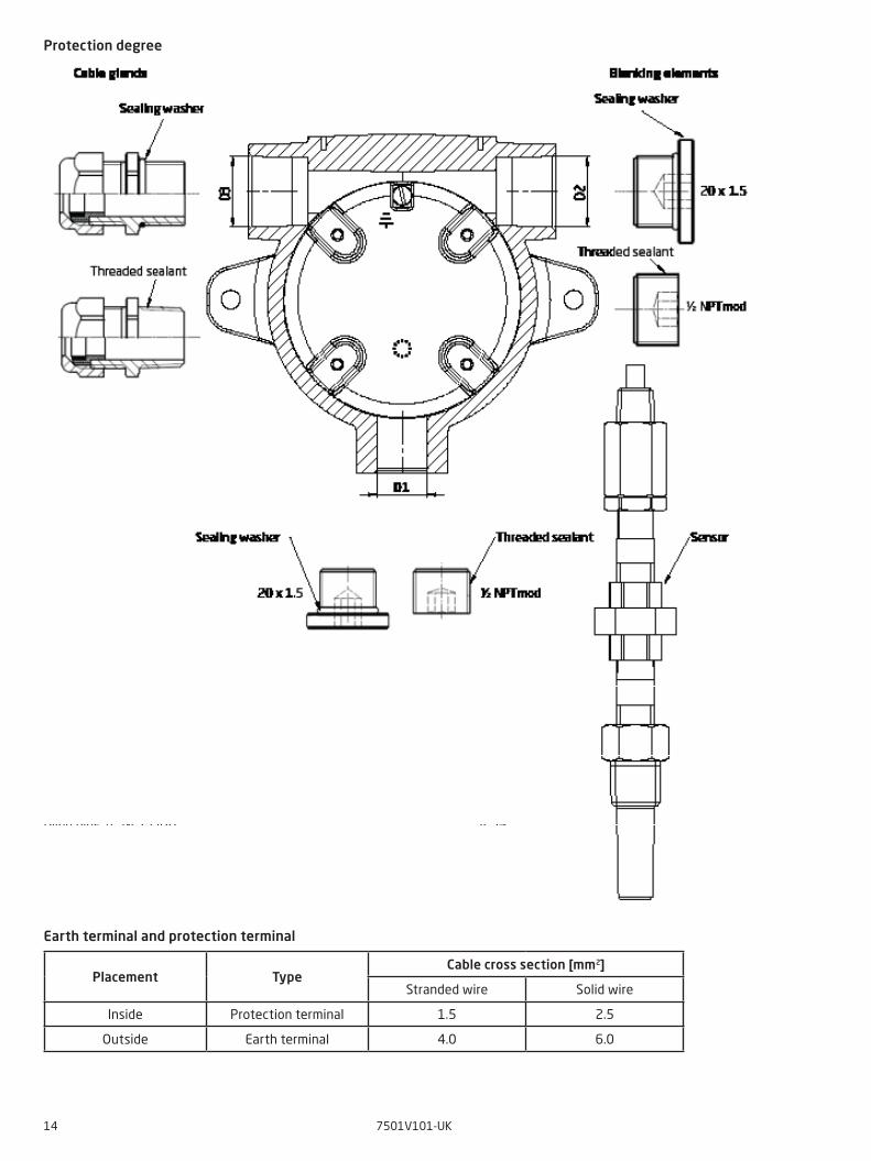
Protection degree
Blind plug M20 . . . . . . . . . . . . . . . . . . . . . . . . . . . . . . . . . . . . . IP54 With O-ring . . . . . . . . . . . . . . . . . . . . . . . . . . . . . . . . . . . . . . IIP66 - IP68 Blind plug ½” NPT MOD . . . . . . . . . . . . . . . . . . . . . . . . . . . . . . . . IP54 With locktite 577 . . . . . . . . . . . . . . . . . . . . . . . . . . . . . . . . . . IIP66 - IP68 Protection degree is defined by the connection with the lowest IP rating It is optional to connect a sensor to any of the three conduit openings
Earth terminal and protection terminal
Placement TypeCable cross section [mm2]
Stranded wire Solid wire
Inside Protection terminal 1.5 2.5
Outside Earth terminal 4.0 6.0

A-F
= 2
mm
7501V101-UK 15
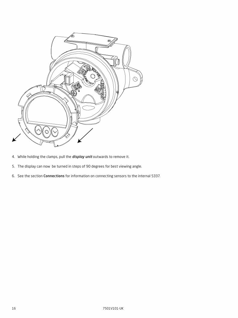
Assembly and disassembly To connect sensor wires to the 7501 or change the orientation of the display, the housing must be disassembled and the internal device must be extracted. This can be done in six easy steps.
!! Disconnect power to the device before disassembly.
1. Release the locking screw, using a hex spanner with a cross-flat of 2 [mm]. This screw is situated on the housing top.2. Unscrew the housing lid by turning it counterclockwise.
Point 3 and 4 only apply to devices with buttons and display.3. Press and hold the two clamps located on the left and right side of the display unit.
Loocking screw
16 7501V101-UK
4. While holding the clamps, pull the display unit outwards to remove it.
5. The display can now be turned in steps of 90 degrees for best viewing angle.
6. See the section Connections for information on connecting sensors to the internal 5337.
7501V101-UK 17
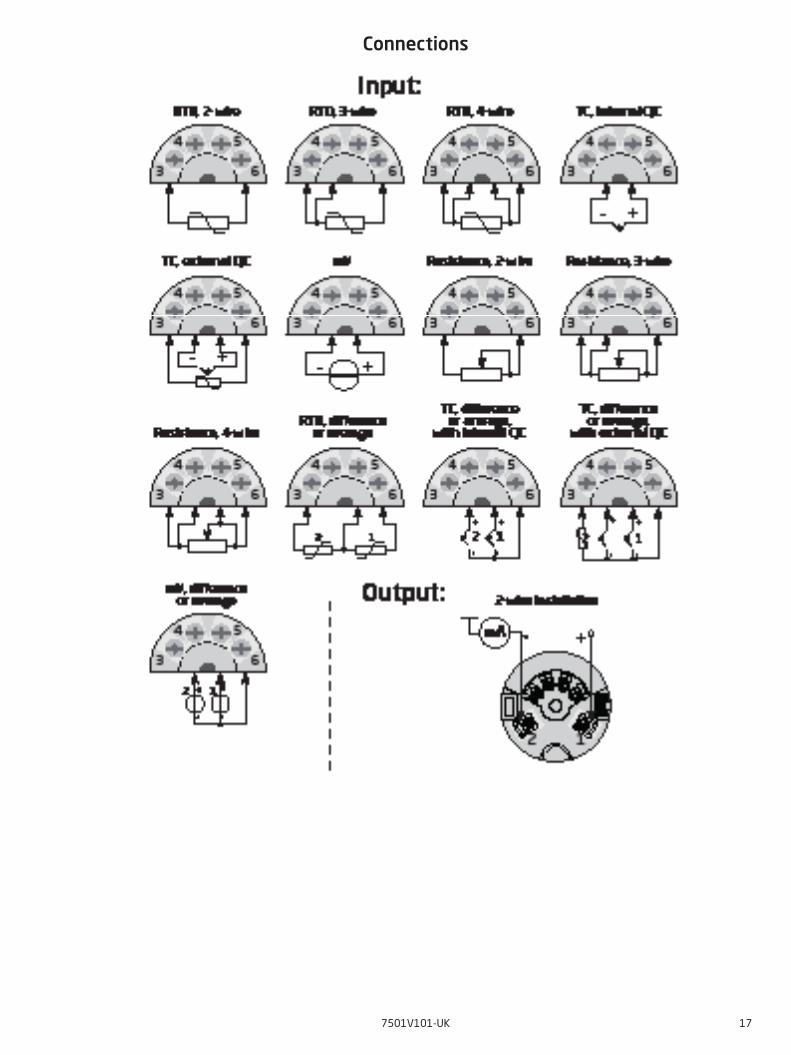
Connections
18 7501V101-UK
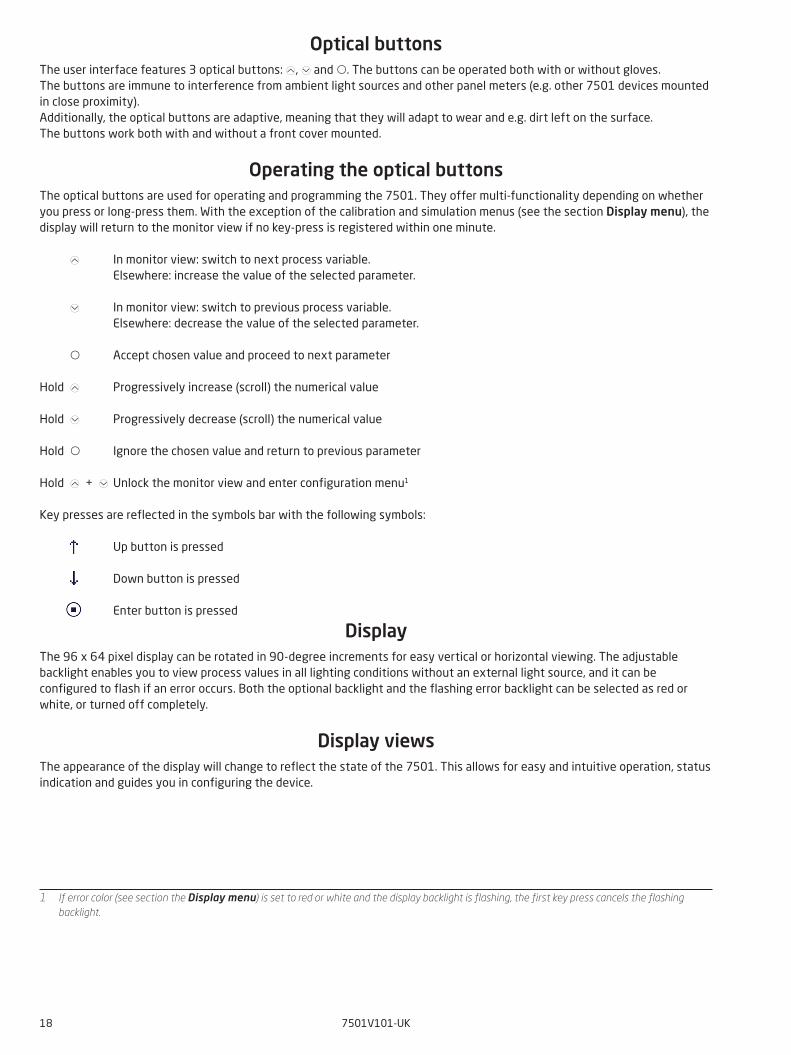
Optical buttonsThe user interface features 3 optical buttons: , 2 and . The buttons can be operated both with or without gloves.The buttons are immune to interference from ambient light sources and other panel meters (e.g. other 7501 devices mounted in close proximity).Additionally, the optical buttons are adaptive, meaning that they will adapt to wear and e.g. dirt left on the surface.The buttons work both with and without a front cover mounted.
Operating the optical buttonsThe optical buttons are used for operating and programming the 7501. They offer multi-functionality depending on whether you press or long-press them. With the exception of the calibration and simulation menus (see the section Display menu), the display will return to the monitor view if no key-press is registered within one minute.
In monitor view: switch to next process variable. Elsewhere: increase the value of the selected parameter.
2 In monitor view: switch to previous process variable. Elsewhere: decrease the value of the selected parameter.
Accept chosen value and proceed to next parameter
Hold Progressively increase (scroll) the numerical value
Hold 2 Progressively decrease (scroll) the numerical value
Hold Ignore the chosen value and return to previous parameter
Hold + 2 Unlock the monitor view and enter configuration menu1
Key presses are reflected in the symbols bar with the following symbols:
Up button is pressed
Down button is pressed
Enter button is pressed
DisplayThe 96 x 64 pixel display can be rotated in 90-degree increments for easy vertical or horizontal viewing. The adjustable backlight enables you to view process values in all lighting conditions without an external light source, and it can be configured to flash if an error occurs. Both the optional backlight and the flashing error backlight can be selected as red or white, or turned off completely.
Display viewsThe appearance of the display will change to reflect the state of the 7501. This allows for easy and intuitive operation, status indication and guides you in configuring the device.
1 If error color (see section the Display menu) is set to red or white and the display backlight is flashing, the first key press cancels the flashing backlight.
7501V101-UK 19
Device TAG
Symbols
Process value unit
Process value
Shown process value
Monitoring view
Bar graph
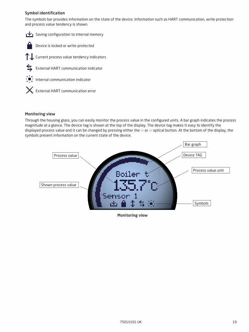
Symbol identification
The symbols bar provides information on the state of the device. Information such as HART communication, write protection and process value tendency is shown.
Saving configuration to internal memory
Device is locked or write-protected
Current process value tendency indicators
External HART communication indicator
Internal communication indicator
External HART communication error
Monitoring view
Through the housing glass, you can easily monitor the process value in the configured units. A bar graph indicates the process magnitude at a glance. The device tag is shown at the top of the display. The device tag makes it easy to identify the displayed process value and it can be changed by pressing either the or 2 optical button. At the bottom of the display, the symbols present information on the current state of the device.
20 7501V101-UK
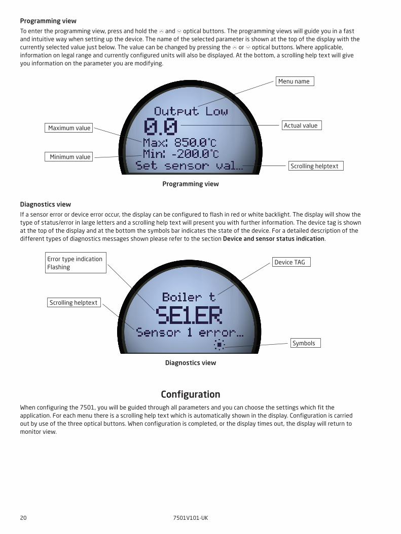
Programming view
To enter the programming view, press and hold the and 2 optical buttons. The programming views will guide you in a fast and intuitive way when setting up the device. The name of the selected parameter is shown at the top of the display with the currently selected value just below. The value can be changed by pressing the or 2 optical buttons. Where applicable, information on legal range and currently configured units will also be displayed. At the bottom, a scrolling help text will give you information on the parameter you are modifying.
Diagnostics view
If a sensor error or device error occur, the display can be configured to flash in red or white backlight. The display will show the type of status/error in large letters and a scrolling help text will present you with further information. The device tag is shown at the top of the display and at the bottom the symbols bar indicates the state of the device. For a detailed description of the different types of diagnostics messages shown please refer to the section Device and sensor status indication.
ConfigurationWhen configuring the 7501, you will be guided through all parameters and you can choose the settings which fit the application. For each menu there is a scrolling help text which is automatically shown in the display. Configuration is carried out by use of the three optical buttons. When configuration is completed, or the display times out, the display will return to monitor view.
Device TAG
Symbols
Error type indication Flashing
Scrolling helptext
Diagnostics view
Menu name
Scrolling helptext
Actual valueMaximum value
Minimum value
Programming view
7501V101-UK 21
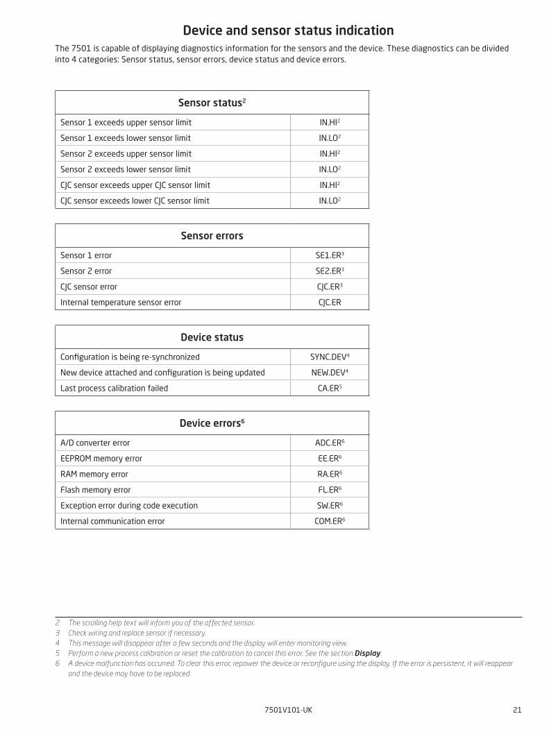
Sensor status2
Sensor 1 exceeds upper sensor limit IN.HI2
Sensor 1 exceeds lower sensor limit IN.LO2
Sensor 2 exceeds upper sensor limit IN.HI2
Sensor 2 exceeds lower sensor limit IN.LO2
CJC sensor exceeds upper CJC sensor limit IN.HI2
CJC sensor exceeds lower CJC sensor limit IN.LO2
Device and sensor status indicationThe 7501 is capable of displaying diagnostics information for the sensors and the device. These diagnostics can be divided into 4 categories: Sensor status, sensor errors, device status and device errors.
Sensor errors
Sensor 1 error SE1.ER3
Sensor 2 error SE2.ER3
CJC sensor error CJC.ER3
Internal temperature sensor error CJC.ER
Device status
Configuration is being re-synchronized SYNC.DEV4
New device attached and configuration is being updated NEW.DEV4
Last process calibration failed CA.ER5
Device errors6
A/D converter error ADC.ER6
EEPROM memory error EE.ER6
RAM memory error RA.ER6
Flash memory error FL.ER6
Exception error during code execution SW.ER6
Internal communication error COM.ER6
2 The scrolling help text will inform you of the affected sensor.3 Check wiring and replace sensor if necessary.4 This message will disappear after a few seconds and the display will enter monitoring view.5 Perform a new process calibration or reset the calibration to cancel this error. See the section Display.6 A device malfunction has occurred. To clear this error, repower the device or reconfigure using the display. If the error is persistent, it will reappear
and the device may have to be replaced.
Power up
Sensor 1 - °C
123.45°C
Device tag
********Password
Txt 1
(Char list)
YesAdv Setup?
Txt 2
No Yes
COM.ERTxt 100
SW.ERFL.EREE.ERADC.ERRA.ERCOM.ER
SE1.ERTxt 100
NEW.DEVSYNC.DEVSE1.ER *19SE2.ER*19CJC.ER*19CA.ER *19
IN.HIIN.LO
22
Device tag Device tag
3 3
*17
*1 *2
*18
HARTSetupTxt 4
DisplayTags
CalibrationSimulationSensorHART
PasswordLanguage
HART revision *24
2
3
2
2
22 7501V101-UK
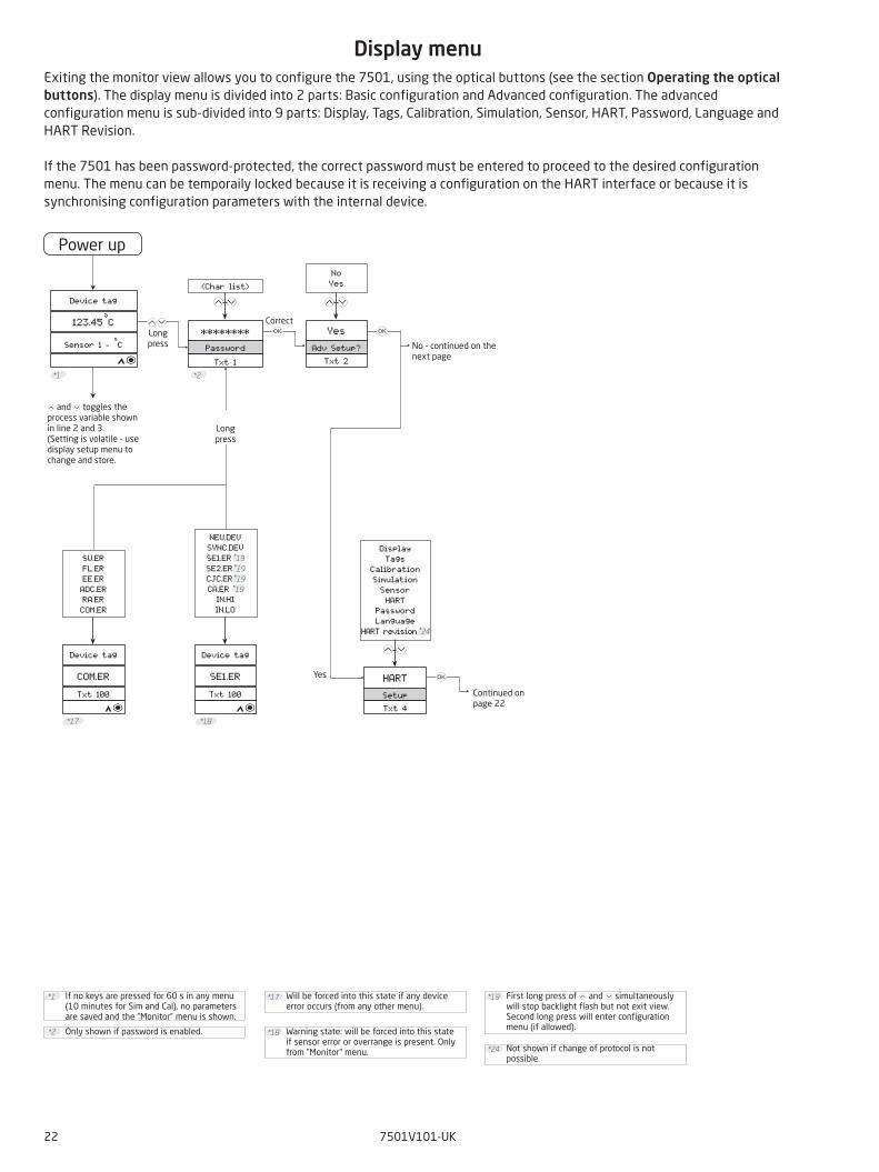
Display menuExiting the monitor view allows you to configure the 7501, using the optical buttons (see the section Operating the optical buttons). The display menu is divided into 2 parts: Basic configuration and Advanced configuration. The advanced configuration menu is sub-divided into 9 parts: Display, Tags, Calibration, Simulation, Sensor, HART, Password, Language and HART Revision.
If the 7501 has been password-protected, the correct password must be entered to proceed to the desired configuration menu. The menu can be temporaily locked because it is receiving a configuration on the HART interface or because it is synchronising configuration parameters with the internal device.
If no keys are pressed for 60 s in any menu (10 minutes for Sim and Cal), no parameters are saved and the ”Monitor” menu is shown.
*1
Only shown if password is enabled.*2
*17 Will be forced into this state if any device error occurs (from any other menu).
Warning state: will be forced into this state if sensor error or overrange is present. Only from ”Monitor” menu.
*18
Not shown if change of protocol is not possible.
*24
First long press of and 2 simultaneously will stop backlight flash but not exit view. Second long press will enter configuration menu (if allowed).
*19
No - continued on the next page
and 2 toggles the process variable shown in line 2 and 3. (Setting is volatile - use display setup menu to change and store.
Continued on page 22
Correct Long press
Long press
Yes
Single SensSensor Func
Txt 3
Single Sens Dual Sens
3-wireConnection
Txt 7
2-wire 3-wire 4-wire
TemperatureInput Type
Txt 69
Voltage Linear Res Temperature
0S1 Wire Res
Txt 8
100.0 0.0
0S2 Wire Res
Txt 8
100.00.0
22222
DifferentialMeas setup
Txt 68
Average Differential
2
Pt100Pt TypeTxt 6
Pt50Pt100Pt200Pt500Pt1000 Custom
PtSensor Type
Txt 70
PtNiTC
3-wireConnection
Txt 7
2-wire 3-wire 4-wire
0S1 Wire Res
Txt 8
100.00.0
2222
0S2 Wire Res
Txt 8
100.00.0
2
Ni100Ni TypeTxt 71
Ni50Ni100Ni120Ni1000
3-wireConnection
Txt 7
2-wire 3-wire 4-wire
0S1 Wire Res
Txt 8
100.00.0
222
0S2 Wire Res
Txt 8
100.00.0
2
TC KTC TypeTxt 72
TC BTC ETC JTC KTC LTC NTC R
TC STC TTC UTC W3TC W5TC LrCustom
Ext Pt100CJC TypeTxt 10
InternalExt Pt100Ext Ni100
Fixed
22
0CJC Wire Res
Txt 8
100.00.0
2
0CJC Wire Res
Txt 8
100.00.0
2
3Pt
Ni
TC
3
3
3
3
3
3
3
3
3 3
*3 *5*4
*3 *5*4
*3 *5*4
7501V101-UK 23
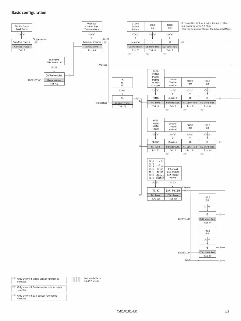
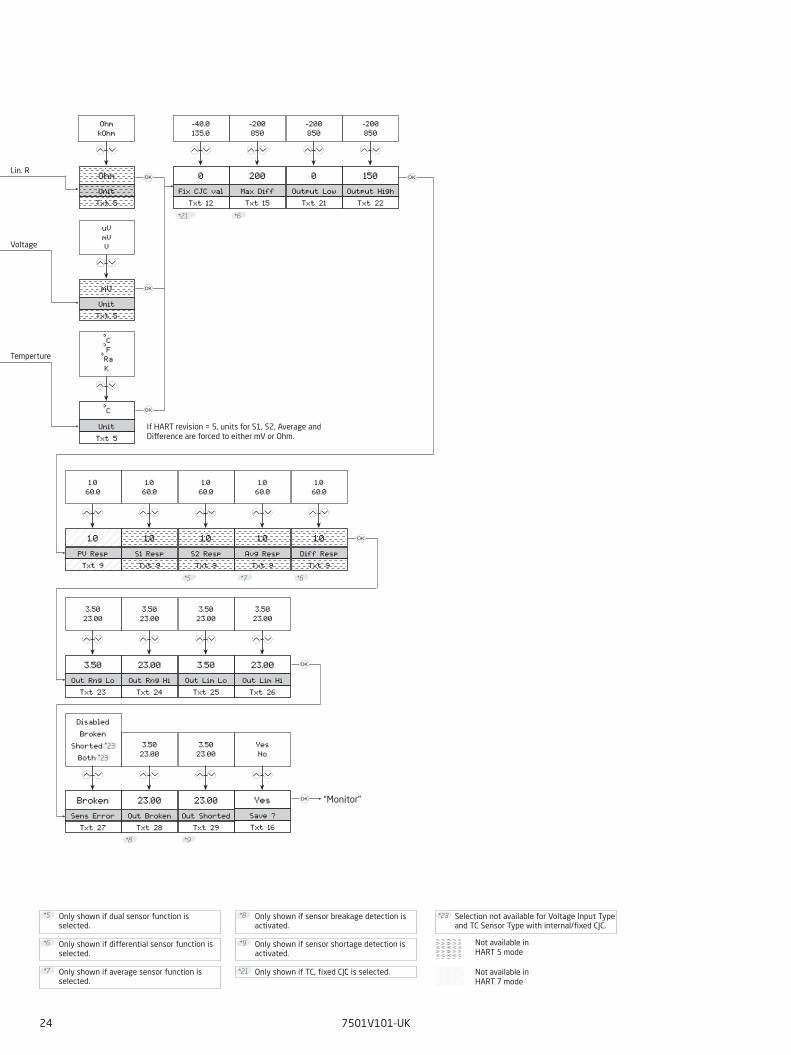
Basic configuration
*4 Only shown if 2-wire sensor connection is selected.
Only shown if single sensor function is selected.
*3
Only shown if dual sensor function is selected.
*5
Not available in HART 5 mode
If connection is 3- or 4-wire, the max. cable resistance is set to 10 Ohm.This can be overwritten in the Advanced Menu.
Ext Pt 100
Ext Ni 100
Fixed
Internal
Single sensor
Dual sensor
Temperture
Voltage
Lin. R
0Fix CJC val
Txt 12
-40.0 135.0
2
200Max DiffTxt 15
-200850
0Output Low
Txt 21
-200850
150Output High
Txt 22
-200850
OhmUnitTxt 5
Ohm kOhm
22 22
mVUnitTxt 5
uVmVV
2
°C
UnitTxt 5
°C°F°RaK
2
1.0PV RespTxt 9
1.060.0
1.0S1 RespTxt 9
1.060.0
22
1.0S2 RespTxt 9
1.060.0
2
1.0Avg RespTxt 9
1.060.0
1.0Diff Resp
Txt 9
1.060.0
22
3.50Out Rng Lo
Txt 23
3.5023.00
23.00Out Rng Hi
Txt 24
3.5023.00
22
3.50Out Lim Lo
Txt 25
3.5023.00
23.00Out Lim HiTxt 26
3.5023.00
22
YesSave ?Txt 16
23.00Out Broken
Txt 28
3.5023.00
23.00Out Shorted
Txt 29
3.5023.00
22
BrokenSens Error
Txt 27
DisabledBroken
Shorted *23Both *23
2
3
3
3
3
3
3
3
*8 *9
*5 *6*7
*6*21
YesNo
2
24 7501V101-UK
Not available in HART 7 mode
*6 Only shown if differential sensor function is selected.
*8 Only shown if sensor breakage detection is activated.
Only shown if average sensor function is selected.
*7
Only shown if sensor shortage detection is activated.
*9
Only shown if dual sensor function is selected.
*5
*21 Only shown if TC, fixed CJC is selected.
*23 Selection not available for Voltage Input Type and TC Sensor Type with internal/fixed CJC.
Not available in HART 5 mode
If HART revision = 5, units for S1, S2, Average and Difference are forced to either mV or Ohm.
Lin. R
Temperture
Voltage
“Monitor”
YesEdit L. Tag
Txt 64
NoYes
TextLong TagTxt 38
(Char list)
YesSave ?Txt 16
22
YesEdit TagTxt 65
NoYes
TextTag
Txt 39
(Char list)
22
YesEdit MsgTxt 67
NoYes
TextMessageTxt 35
(Char list)
22
YesEdit Descr
Txt 66
NoYes
TextDescriptor
Txt 34
(Char list)
22
3
*16 *16 *16 *16
YesNo
2
WhiteBacklightTxt 42
OffWhiteRed
WhiteError color
Txt 73
OffWhiteRed
3ContrastTxt 43
09
222
% RangeBar graphTxt 44
Loop Curr% Range
Sensor 2MonitorTxt 45
Sensor 1Sensor 2 *5CJC SensorAverage *7
Differential *6Loop Curr% Range
YesSave ?Txt 16
22
3
*25
YesNo
2
7501V101-UK 25
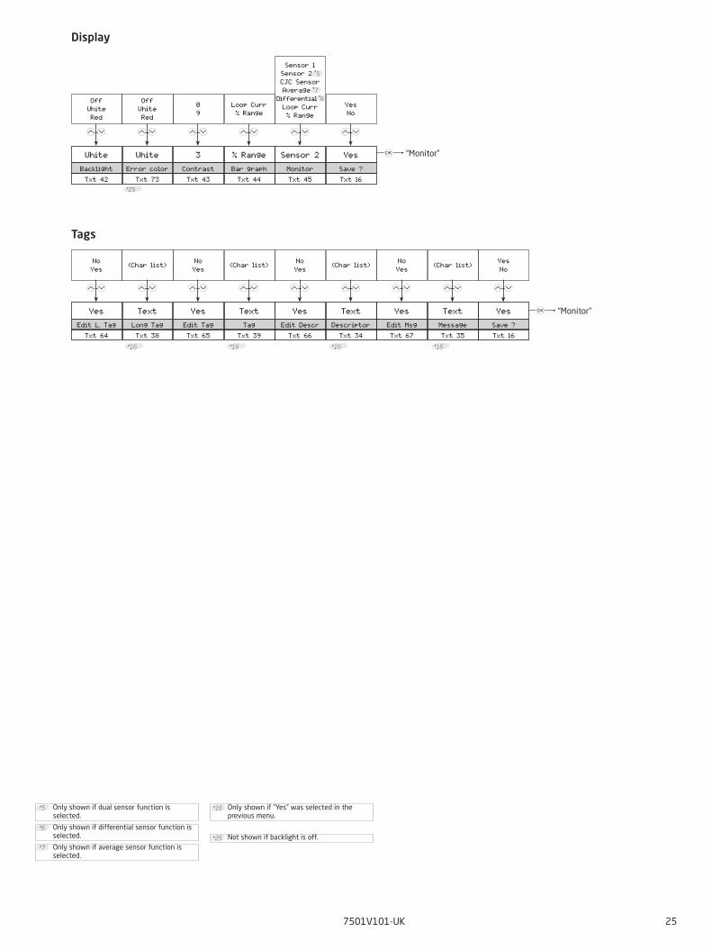
Display
Tags
*25 Not shown if backlight is off.
Only shown if ”Yes” was selected in the previous menu.
*16
*6 Only shown if differential sensor function is selected.
Only shown if dual sensor function is selected.
*5
Only shown if average sensor function is selected.
*7
“Monitor”
“Monitor”
Sensor 2Calibration
Txt 53
Sensor 1Sensor 2 *5CJC sensorLoop Curr *26
2
Do CalibS2 CalibTxt 54
Reset CalibDo Calib
2
Do CalibLoop CalibTxt 54
Reset CalibDo Calib
2
3
*5
Set S2 LowTxt 74
0.0S2 Cal Low
Txt 55
-200°C850°C
2
*27 *14
4.00Calib 4 mATxt 55
3.50 mA23.00 mA
20.00Calib 20 mA
Txt 56
3.50 mA23.00 mA
22
*12 *13
Do CalibS1 CalibTxt 54
Reset CalibDo Calib
2
Do CalibCJC CalibTxt 54
Reset CalibDo Calib
2
Set S1 LowTxt 74
0.0S1 Cal LowTxt 55
-200°C850°C
2
*27 *14
Set CJC LowTxt 74
0.0CJC Cal Low
Txt 55
-40.0135.0
2
*27 *14
3
3
3
3
3
3
33
Set S2 HighTxt 75
*27
100.0S2 Cal High
Txt 56
-200°C850°C
2
*14
Set S1 HighTxt 75
*27
100.0S1 Cal High
Txt 56
-200°C850°C
2
*14
Set CJC HighTxt 75
*27
100.0CJC Cal HiTxt 56
-40.0135.0
2
*14*26
26 7501V101-UK
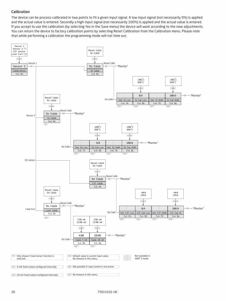
Calibration
The device can be process-calibrated in two points to fit a given input signal. A low input signal (not necessarily 0%) is applied and the actual value is entered. Secondly a high input signal (not necessarily 100%) is applied and the actual value is entered. If you accept to use the calibration (by selecting Yes in the Save menu) the device will work according to the new adjustments. You can return the device to factory calibration points by selecting Reset Calibration from the Calibration menu. Please note that while performing a calibration the programming mode will not time out.
Only shown if dual sensor function is selected.
*5
*13 20 mA fixed output configured internally.
4 mA fixed output configured internally.*12
Default value is current input value.No timeout in this menu.
*14
*26 Not possible if Loop Current is not active.
*27 No timeout in this menu.
Not available in HART 5 mode
Sensor 2
Loop Curr
Sensor 1
CJC sensor
Reset Calib
Do Calib
Reset Calib
Do Calib
Reset Calib
Do Calib
Reset Calib
Do Calib
“Monitor”
“Monitor”
“Monitor”
“Monitor”
“Monitor”
“Monitor”
“Monitor”“Monitor”
Sensor 2SimulationTxt 57
Sensor 1Sensor 2 *5CJC SensorAverage *5
Differential *5Loop Curr *26
2
20.0S2 SimulTxt 59
-200.0850.0
2
20.0Avg SimulTxt 61
-200.0850.0
2
3
20.00Loop TestTxt 63
3.5 mA23.0 mA
2
20.0S1 SimulTxt 58
-200.0850.0
2
20.0CJC SimulTxt 60
-40.0135.0
2
20.0Diff SimulTxt 62
-200.0850.0
2
3
3
3
3
3
3
7501V101-UK 27
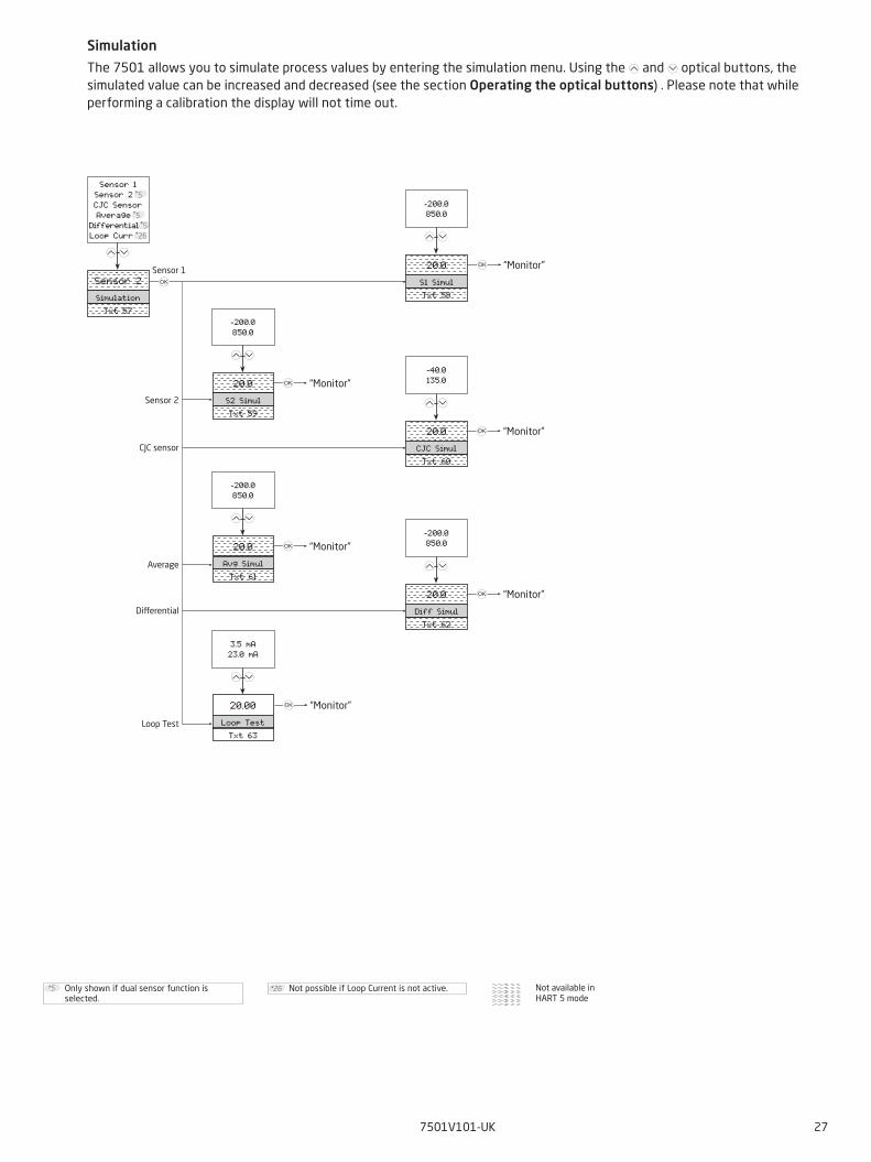
Simulation
The 7501 allows you to simulate process values by entering the simulation menu. Using the and 2 optical buttons, the simulated value can be increased and decreased (see the section Operating the optical buttons) . Please note that while performing a calibration the display will not time out.
Only shown if dual sensor function is selected.
*5 Not available in HART 5 mode
*26 Not possible if Loop Current is not active.
Sensor 2
Average
Sensor 1
CJC sensor
Differential
Loop Test
“Monitor”
“Monitor”
“Monitor”
“Monitor”
“Monitor”
“Monitor”
Req preambDev infoTxt 50
Req PreambSW RevHW Rev
Device IDManuf IDHART Rev
5Resp Preamb
Txt 31
520
22
0Poll AddrTxt 32
063
YesLoop Enable
Txt 33
NoYes
YesSave ?Txt 16
22
3
*11
YesNo
2
0Assembly Nr
Txt 37
016777215
01-06-2015Date
Txt 36
DD-MM-YYYY
22
mVPV UnitTxt 5
All units
mVS1 UnitTxt 5
All units
22
mVS2 UnitTxt 5
All units
°FCJC UnitTxt 5
°C°FK
°Ra
YesSave ?Txt 16
22
mVAvg UnitTxt 5
All units
mVDiff UnitTxt 5
All units
22
Sensor 2Assign TVTxt 19
Sensor 1Sensor 2 *5CJC SensorAverage *5
Differential *5
Sensor 2Assign QVTxt 20
Sensor 1Sensor 2 *5CJC SensorAverage *5
Differential *5
22
Sensor 2Assign PVTxt 17
Sensor 1Sensor 2 *5CJC SensorAverage *5
Differential *5
Sensor 2Assign SVTxt 18
Sensor 1Sensor 2 *5CJC SensorAverage *5
Differential *5
22
3
*5*5 *5
1.0CJC Resp Txt 9
60.01.0
2
*20*22
0Max Wire Res
Txt 14
100.00.0
2
YesNo
2
28 7501V101-UK
Sensor
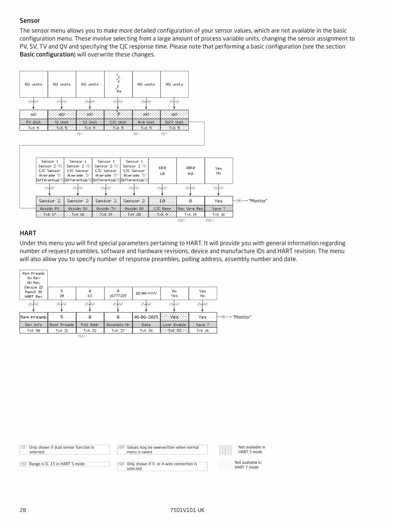
The sensor menu allows you to make more detailed configuration of your sensor values, which are not available in the basic configuration menu. These involve selecting from a large amount of process variable units, changing the sensor assignment to PV, SV, TV and QV and specifying the CJC response time. Please note that performing a basic configuration (see the section Basic configuration) will overwrite these changes.
HART
Under this menu you will find special parameters pertaining to HART. It will provide you with general information regarding number of request preambles, software and hardware revisions, device and manufacture IDs and HART revision. The menu will also allow you to specify number of response preambles, polling address, assembly number and date.
Only shown if dual sensor function is selected.
*5
*11 Range is 0...15 in HART 5 mode.
Values may be owerwritten when normal menu is saved.
*20
Only shown if 3- or 4-wire connection is selected.
*22 Not available in HART 7 mode
Not available in HART 5 mode
“Monitor”
“Monitor”
YesSave ?Txt 16
HART 7HART RevTxt 51
3
HART 7HART 5
2
*24
YesNo
2
YesSave ?Txt 16
DanskLanguageTxt 41
English Dansk
Deutsch Français Svenska Italiano Español
2
3
YesNo
2
YesSave ?Txt 16
YesEnable Passw
Txt 47
YesNo
2
3
********New Password
Txt 48
(Char list)
2
3
3
YesNo
2
7501V101-UK 29
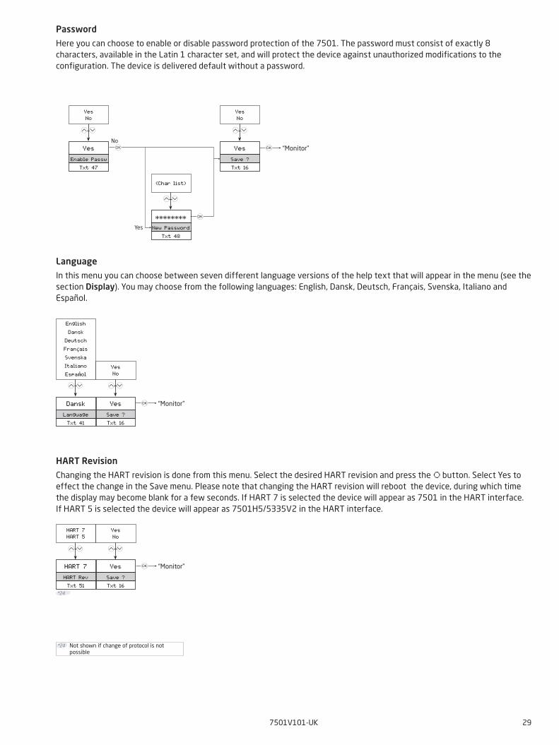
Password
Here you can choose to enable or disable password protection of the 7501. The password must consist of exactly 8 characters, available in the Latin 1 character set, and will protect the device against unauthorized modifications to the configuration. The device is delivered default without a password.
Language
In this menu you can choose between seven different language versions of the help text that will appear in the menu (see the section Display). You may choose from the following languages: English, Dansk, Deutsch, Français, Svenska, Italiano and Español.
HART Revision
Changing the HART revision is done from this menu. Select the desired HART revision and press the button. Select Yes to effect the change in the Save menu. Please note that changing the HART revision will reboot the device, during which time the display may become blank for a few seconds. If HART 7 is selected the device will appear as 7501 in the HART interface.If HART 5 is selected the device will appear as 7501H5/5335V2 in the HART interface.
Not shown if change of protocol is not possible
*24
“Monitor”
“Monitor”No
Yes
“Monitor”
30 7501V101-UK
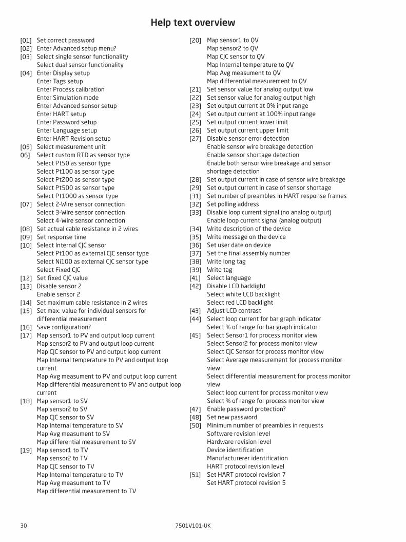
Help text overview
[01] [02] [03] [04] [05] 06] [07] [08] [09] [10] [12] [13] [14] [15] [16] [17] [18] [19]
[20] [21] [22] [23] [24] [25] [26] [27] [28] [29] [31] [32] [33] [34] [35] [36] [37] [38] [39] [41] [42] [43] [44] [45] [47] [48] [50] [51]
Set correct passwordEnter Advanced setup menu?Select single sensor functionalitySelect dual sensor functionalityEnter Display setupEnter Tags setupEnter Process calibrationEnter Simulation modeEnter Advanced sensor setupEnter HART setupEnter Password setupEnter Language setupEnter HART Revision setupSelect measurement unitSelect custom RTD as sensor type Select Pt50 as sensor typeSelect Pt100 as sensor typeSelect Pt200 as sensor typeSelect Pt500 as sensor typeSelect Pt1000 as sensor typeSelect 2-Wire sensor connectionSelect 3-Wire sensor connectionSelect 4-Wire sensor connectionSet actual cable resistance in 2 wiresSet response timeSelect Internal CJC sensor Select Pt100 as external CJC sensor typeSelect Ni100 as external CJC sensor typeSelect Fixed CJC Set fixed CJC valueDisable sensor 2Enable sensor 2Set maximum cable resistance in 2 wiresSet max. value for individual sensors for differential measurementSave configuration?Map sensor1 to PV and output loop currentMap sensor2 to PV and output loop current Map CJC sensor to PV and output loop currentMap Internal temperature to PV and output loop current Map Avg measument to PV and output loop currentMap differential measurement to PV and output loop currentMap sensor1 to SVMap sensor2 to SVMap CJC sensor to SVMap Internal temperature to SVMap Avg measument to SVMap differential measurement to SVMap sensor1 to TVMap sensor2 to TVMap CJC sensor to TVMap Internal temperature to TVMap Avg measument to TVMap differential measurement to TV
Map sensor1 to QVMap sensor2 to QVMap CJC sensor to QVMap Internal temperature to QVMap Avg measument to QVMap differential measurement to QVSet sensor value for analog output lowSet sensor value for analog output highSet output current at 0% input rangeSet output current at 100% input rangeSet output current lower limitSet output current upper limitDisable sensor error detectionEnable sensor wire breakage detectionEnable sensor shortage detectionEnable both sensor wire breakage and sensor shortage detectionSet output current in case of sensor wire breakageSet output current in case of sensor shortageSet number of preambles in HART response framesSet polling addressDisable loop current signal (no analog output) Enable loop current signal (analog output)Write description of the deviceWrite message on the deviceSet user date on deviceSet the final assembly numberWrite long tagWrite tagSelect languageDisable LCD backlightSelect white LCD backlightSelect red LCD backlightAdjust LCD contrastSelect loop current for bar graph indicatorSelect % of range for bar graph indicatorSelect Sensor1 for process monitor viewSelect Sensor2 for process monitor viewSelect CJC Sensor for process monitor viewSelect Average measurement for process monitor viewSelect differential measurement for process monitor viewSelect loop current for process monitor viewSelect % of range for process monitor viewEnable password protection?Set new passwordMinimum number of preambles in requestsSoftware revision levelHardware revision levelDevice identificationManufacturerer identificationHART protocol revision levelSet HART protocol revision 7Set HART protocol revision 5
7501V101-UK 31
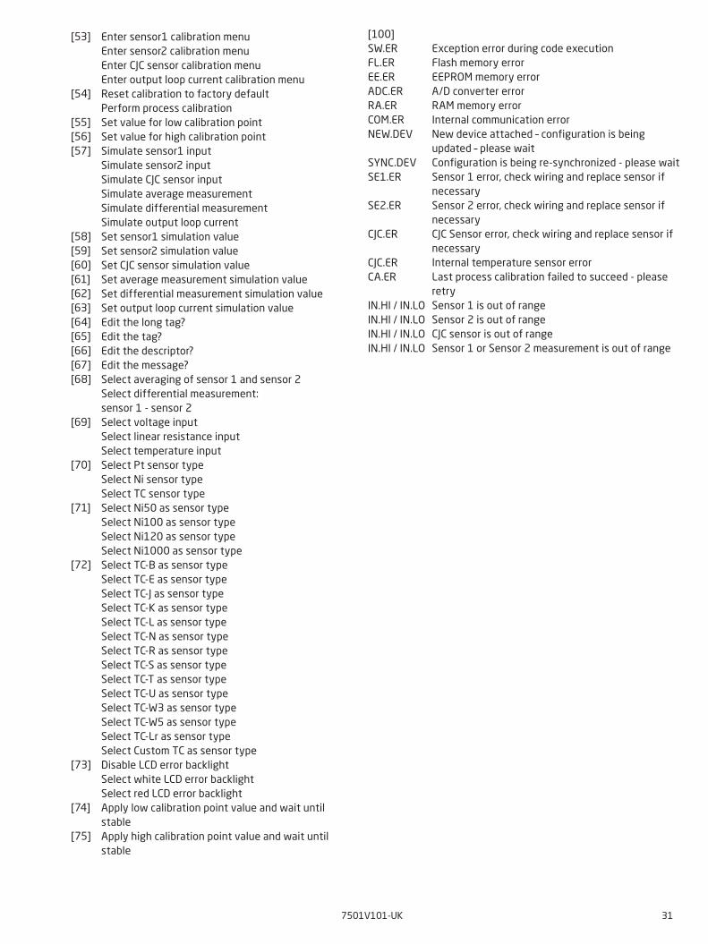
Enter sensor1 calibration menuEnter sensor2 calibration menuEnter CJC sensor calibration menuEnter output loop current calibration menu Reset calibration to factory defaultPerform process calibrationSet value for low calibration pointSet value for high calibration pointSimulate sensor1 inputSimulate sensor2 inputSimulate CJC sensor inputSimulate average measurementSimulate differential measurementSimulate output loop currentSet sensor1 simulation valueSet sensor2 simulation valueSet CJC sensor simulation valueSet average measurement simulation valueSet differential measurement simulation valueSet output loop current simulation valueEdit the long tag?Edit the tag?Edit the descriptor?Edit the message?Select averaging of sensor 1 and sensor 2Select differential measurement: sensor 1 - sensor 2Select voltage inputSelect linear resistance inputSelect temperature inputSelect Pt sensor typeSelect Ni sensor typeSelect TC sensor typeSelect Ni50 as sensor typeSelect Ni100 as sensor typeSelect Ni120 as sensor typeSelect Ni1000 as sensor typeSelect TC-B as sensor typeSelect TC-E as sensor typeSelect TC-J as sensor typeSelect TC-K as sensor typeSelect TC-L as sensor typeSelect TC-N as sensor typeSelect TC-R as sensor typeSelect TC-S as sensor typeSelect TC-T as sensor typeSelect TC-U as sensor typeSelect TC-W3 as sensor type Select TC-W5 as sensor typeSelect TC-Lr as sensor type Select Custom TC as sensor type Disable LCD error backlightSelect white LCD error backlightSelect red LCD error backlight Apply low calibration point value and wait until stable Apply high calibration point value and wait until stable
[53] [54] [55] [56] [57] [58] [59] [60] [61] [62] [63] [64] [65] [66] [67] [68] [69] [70] [71] [72] [73] [74] [75]
[100]SW.ERFL.EREE.ERADC.ERRA.ERCOM.ERNEW.DEV
SYNC.DEVSE1.ER
SE2.ER
CJC.ER
CJC.ERCA.ER
IN.HI / IN.LOIN.HI / IN.LOIN.HI / IN.LOIN.HI / IN.LO
Exception error during code executionFlash memory errorEEPROM memory errorA/D converter errorRAM memory errorInternal communication errorNew device attached – configuration is being updated – please waitConfiguration is being re-synchronized - please waitSensor 1 error, check wiring and replace sensor if necessarySensor 2 error, check wiring and replace sensor if necessaryCJC Sensor error, check wiring and replace sensor if necessaryInternal temperature sensor errorLast process calibration failed to succeed - please retrySensor 1 is out of rangeSensor 2 is out of rangeCJC sensor is out of rangeSensor 1 or Sensor 2 measurement is out of range
32 7501V101-UK
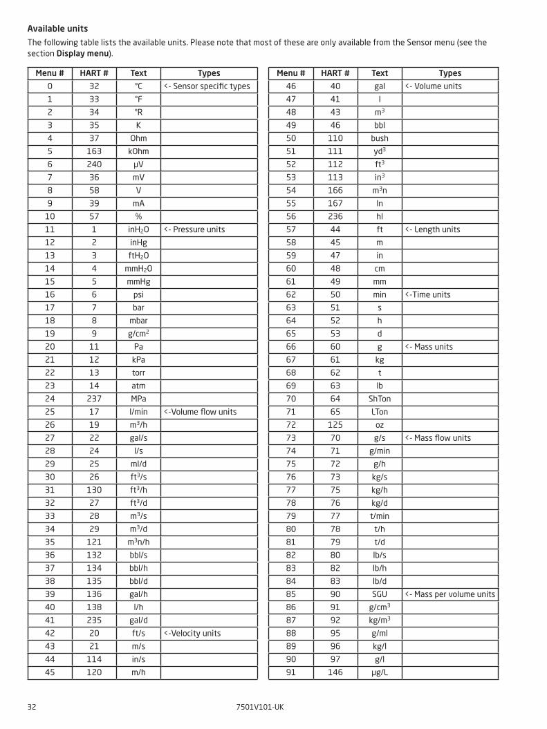
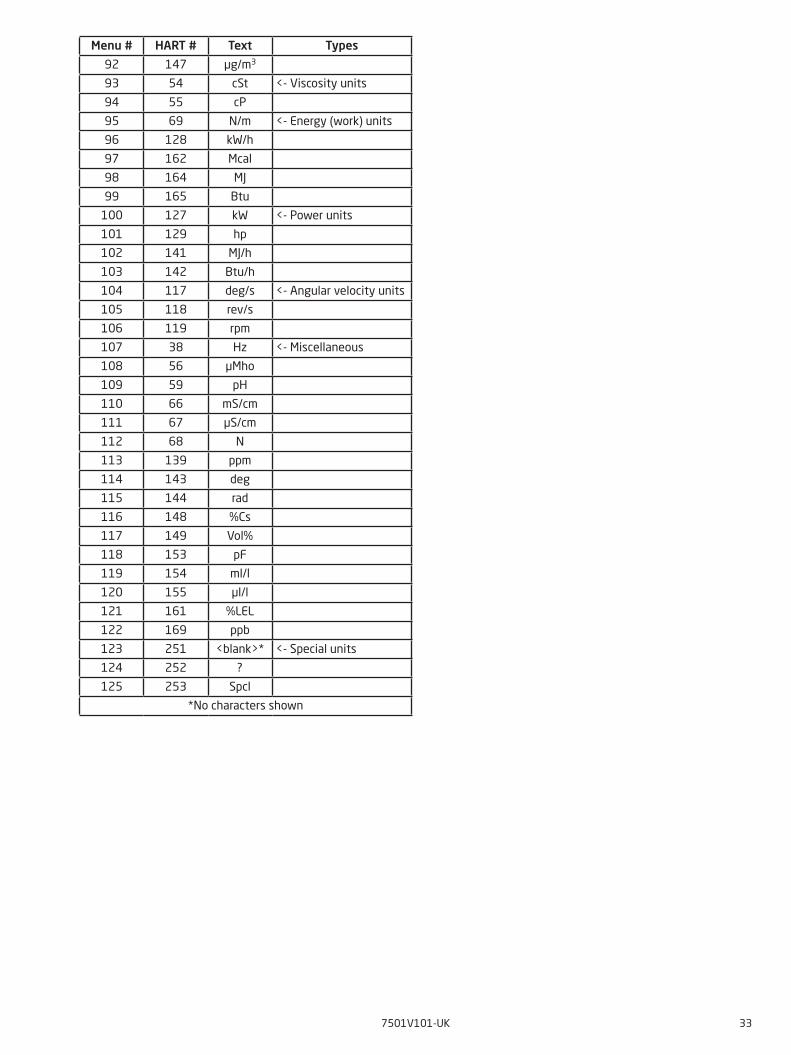
Available units
The following table lists the available units. Please note that most of these are only available from the Sensor menu (see the section Display menu).
Menu # HART # Text Types
0 32 °C <- Sensor specific types
1 33 °F
2 34 °R
3 35 K
4 37 Ohm
5 163 kOhm
6 240 µV
7 36 mV
8 58 V
9 39 mA
10 57 %
11 1 inH2O <- Pressure units
12 2 inHg
13 3 ftH2O
14 4 mmH2O
15 5 mmHg
16 6 psi
17 7 bar
18 8 mbar
19 9 g/cm2
20 11 Pa
21 12 kPa
22 13 torr
23 14 atm
24 237 MPa
25 17 l/min <-Volume flow units
26 19 m3/h
27 22 gal/s
28 24 l/s
29 25 ml/d
30 26 ft3/s
31 130 ft3/h
32 27 ft3/d
33 28 m3/s
34 29 m3/d
35 121 m3n/h
36 132 bbl/s
37 134 bbl/h
38 135 bbl/d
39 136 gal/h
40 138 l/h
41 235 gal/d
42 20 ft/s <-Velocity units
43 21 m/s
44 114 in/s
45 120 m/h
Menu # HART # Text Types
46 40 gal <- Volume units
47 41 l
48 43 m3
49 46 bbl
50 110 bush
51 111 yd3
52 112 ft3
53 113 in3
54 166 m3n
55 167 ln
56 236 hl
57 44 ft <- Length units
58 45 m
59 47 in
60 48 cm
61 49 mm
62 50 min <-Time units
63 51 s
64 52 h
65 53 d
66 60 g <- Mass units
67 61 kg
68 62 t
69 63 lb
70 64 ShTon
71 65 LTon
72 125 oz
73 70 g/s <- Mass flow units
74 71 g/min
75 72 g/h
76 73 kg/s
77 75 kg/h
78 76 kg/d
79 77 t/min
80 78 t/h
81 79 t/d
82 80 lb/s
83 82 lb/h
84 83 lb/d
85 90 SGU <- Mass per volume units
86 91 g/cm3
87 92 kg/m3
88 95 g/ml
89 96 kg/l
90 97 g/l
91 146 µg/L
7501V101-UK 33
Menu # HART # Text Types
92 147 µg/m3
93 54 cSt <- Viscosity units
94 55 cP
95 69 N/m <- Energy (work) units
96 128 kW/h
97 162 Mcal
98 164 MJ
99 165 Btu
100 127 kW <- Power units
101 129 hp
102 141 MJ/h
103 142 Btu/h
104 117 deg/s <- Angular velocity units
105 118 rev/s
106 119 rpm
107 38 Hz <- Miscellaneous
108 56 µMho
109 59 pH
110 66 mS/cm
111 67 µS/cm
112 68 N
113 139 ppm
114 143 deg
115 144 rad
116 148 %Cs
117 149 Vol%
118 153 pF
119 154 ml/l
120 155 µl/l
121 161 %LEL
122 169 ppb
123 251 <blank>* <- Special units
124 252 ?
125 253 Spcl
*No characters shown
34 7501V101-UK
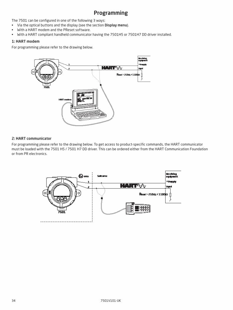
ProgrammingThe 7501 can be configured in one of the following 3 ways:• Via the optical buttons and the display (see the section Display menu).• With a HART modem and the PReset software.• With a HART compliant handheld communicator having the 7501H5 or 7501H7 DD driver installed.
1: HART modem
For programming please refer to the drawing below.
2: HART communicator
For programming please refer to the drawing below. To get access to product-specific commands, the HART communicator must be loaded with the 7501 H5 / 7501 H7 DD driver. This can be ordered either from the HART Communication Foundation or from PR electronics.
7501V101-UK 35
Changing the HART protocol versionIt is possible to change the HART protocol revision of the device by means of the display, utilizing the PReset software and a HART modem or other HART configuration tools such as handheld HART terminals.
Changing the HART revision using the display and the optical buttons
Changing the revision is done from the HART revision view under the Advanced menu. Use the or 2 optical buttons to select the desired HART revision. Press the button to accept the revision and change to the Save view. Select Yes and press to acknowledge the change or No to cancel.
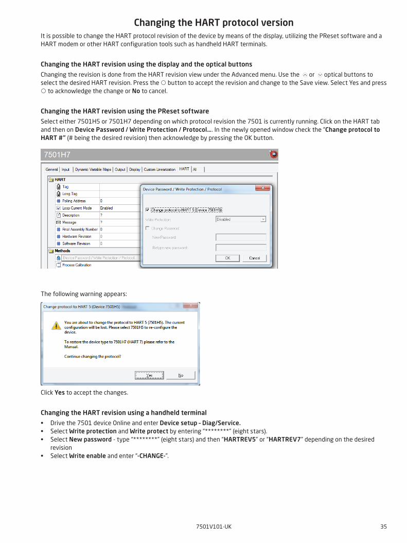
Changing the HART revision using the PReset software
Select either 7501H5 or 7501H7 depending on which protocol revision the 7501 is currently running. Click on the HART tab and then on Device Password / Write Protection / Protocol…. In the newly opened window check the “Change protocol to HART #” (# being the desired revision) then acknowledge by pressing the OK button.
The following warning appears:
Click Yes to accept the changes.
Changing the HART revision using a handheld terminal
• Drive the 7501 device Online and enter Device setup – Diag/Service.• Select Write protection and Write protect by entering “********” (eight stars).• Select New password - type “********” (eight stars) and then “HARTREV5” or “HARTREV7” depending on the desired
revision• Select Write enable and enter “-CHANGE-”.
36 7501V101-UK
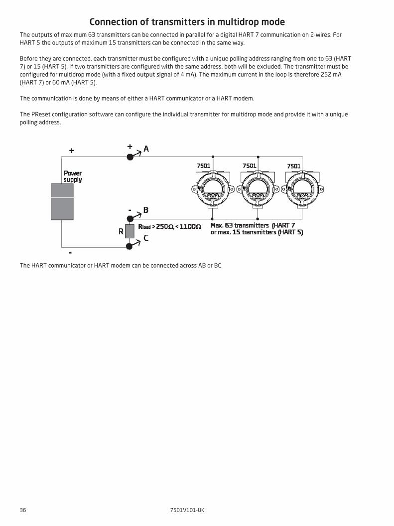
Connection of transmitters in multidrop modeThe outputs of maximum 63 transmitters can be connected in parallel for a digital HART 7 communication on 2-wires. For HART 5 the outputs of maximum 15 transmitters can be connected in the same way.
Before they are connected, each transmitter must be configured with a unique polling address ranging from one to 63 (HART 7) or 15 (HART 5). If two transmitters are configured with the same address, both will be excluded. The transmitter must be configured for multidrop mode (with a fixed output signal of 4 mA). The maximum current in the loop is therefore 252 mA (HART 7) or 60 mA (HART 5).
The communication is done by means of either a HART communicator or a HART modem.
The PReset configuration software can configure the individual transmitter for multidrop mode and provide it with a unique polling address.
The HART communicator or HART modem can be connected across AB or BC.
7501V101-UK 37
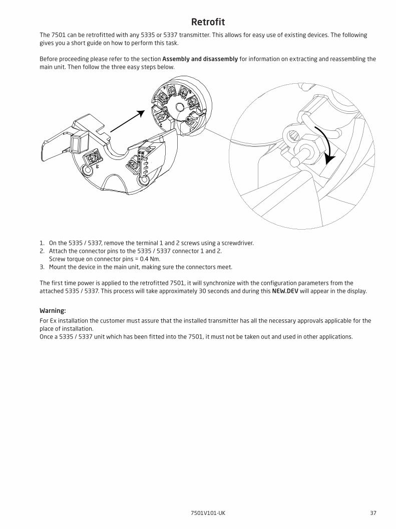
RetrofitThe 7501 can be retrofitted with any 5335 or 5337 transmitter. This allows for easy use of existing devices. The following gives you a short guide on how to perform this task.
Before proceeding please refer to the section Assembly and disassembly for information on extracting and reassembling the main unit. Then follow the three easy steps below.
1. On the 5335 / 5337, remove the terminal 1 and 2 screws using a screwdriver.2. Attach the connector pins to the 5335 / 5337 connector 1 and 2. Screw torque on connector pins = 0.4 Nm.3. Mount the device in the main unit, making sure the connectors meet.
The first time power is applied to the retrofitted 7501, it will synchronize with the configuration parameters from the attached 5335 / 5337. This process will take approximately 30 seconds and during this NEW.DEV will appear in the display.
Warning:
For Ex installation the customer must assure that the installed transmitter has all the necessary approvals applicable for the place of installation.Once a 5335 / 5337 unit which has been fitted into the 7501, it must not be taken out and used in other applications.
Appendix
ATEX Installation Drawing
IECEx installation drawing
FM Installation Drawing
CSA Installation Drawing
Desenho de Instalaçao INMETRO
38 7501V101-UK
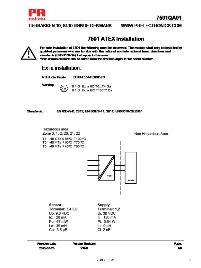
ATEX Installation Drawing
7501V101-UK 39
40 7501V101-UK
7501V101-UK 41
42 7501V101-UK
7501V101-UK 43

44 7501V101-UK
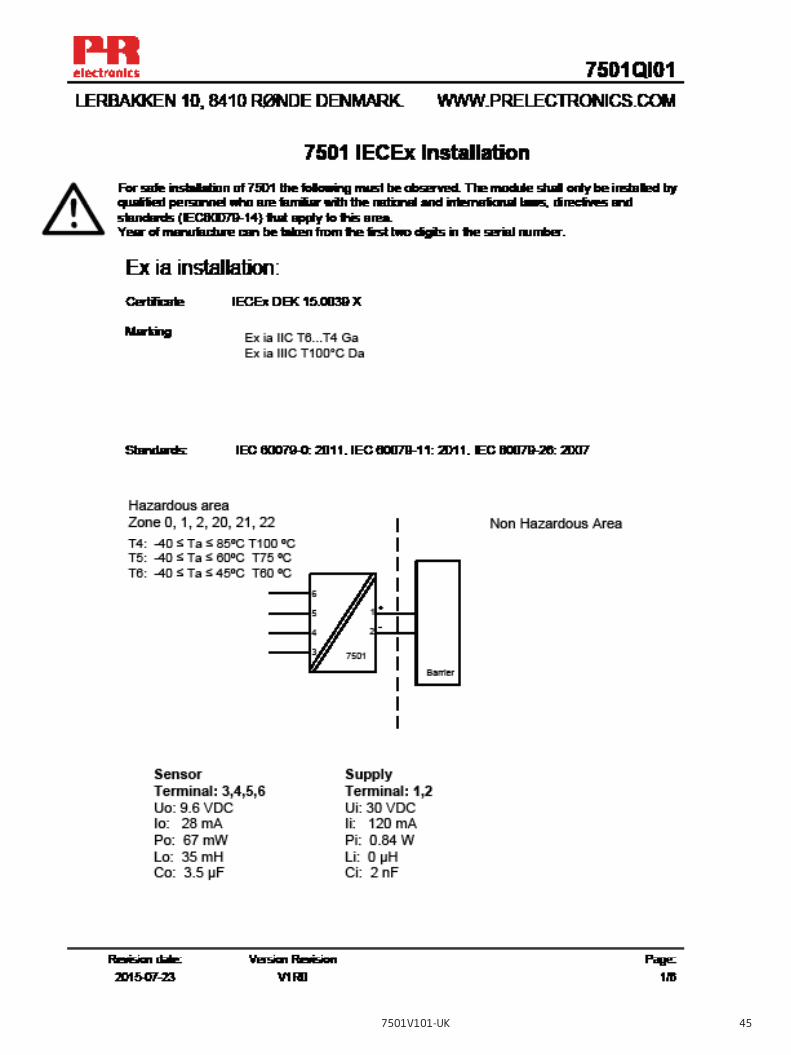
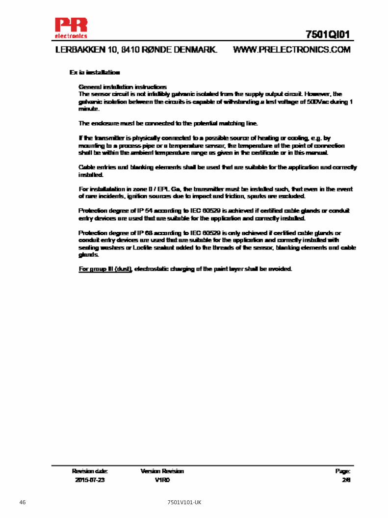
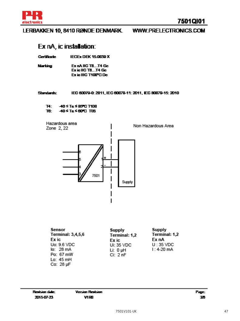
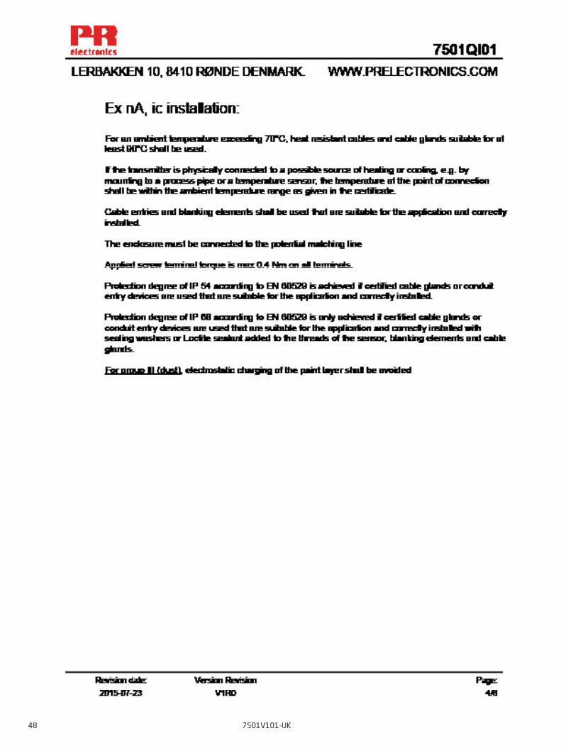
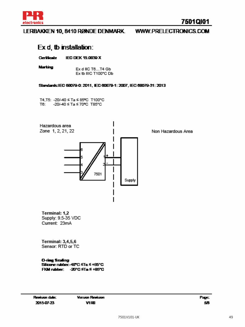
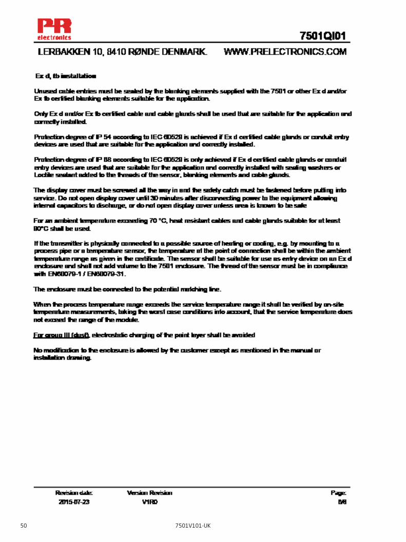
IECEx Installation Drawing
7501V101-UK 45
46 7501V101-UK
7501V101-UK 47
48 7501V101-UK
7501V101-UK 49
50 7501V101-UK
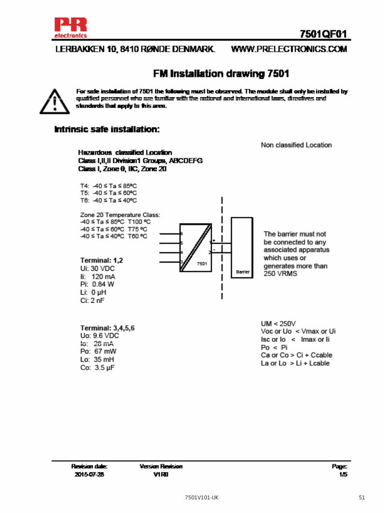
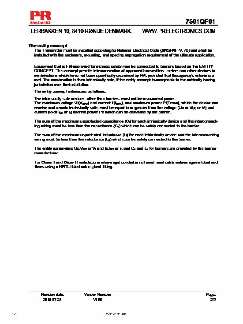
FM Installation Drawing
7501V101-UK 51
52 7501V101-UK
7501V101-UK 53
54 7501V101-UK
7501V101-UK 55

56 7501V101-UK
Document historyThe following list provides notes concerning revisions of this document.
Rev. ID Date Notes100 1524 initial release of the product 101 1530 FM installation drawing updated Application drawing updated

We are near you,all over the world
All our devices are backed by expert service and a 5-year warranty. With each product you purchase, you receive personal technical support and guidance, day-to-day delivery, repair without charge within the warranty period and easily accessible documentation.
We are headquartered in Denmark, and have offices and authorized partners the world over. We are a local
business with a global reach. This means that we are always nearby and know your local markets well. We are committed to your satisfaction and provide PERFORMANCE MADE SMARTER all around the world.
For more information on our warranty program, or to meet with a sales representative in your region, visit prelectronics.com.
Our trusted red boxes are supported wherever you are

www.prelectronics.com
PR electronics is the leading technology company specialized in making industrial process control safer, more reliable and more efficient. Since 1974, we have been dedicated to perfecting our core competence of innovating high precision technology with low power consumption. This dedication continues to set new standards for products communicating, monitoring and connecting our customers’ process measurement points to their process control systems.
Our innovative, patented technologies are derived from our extensive R&D facilities and from having a great understanding of our customers’ needs and processes. We are guided by principles of simplicity, focus, courage and excellence, enabling some of the world’s greatest companies to achieve PERFORMANCE MADE SMARTER.
Benefit today from PERFORMANCE MADE SMARTER