Embed Size (px)
Citation preview
801
649
DIVISION 800 STRUCTURES
SECTION 801
EXCAVATION AND BACKFILLING 801.01 Description. The work under this item shall include the
removal of material, of whatever nature, necessary for the construction of foundations for bridges, box culverts, and retaining walls according to the plans or as directed. It shall include the furnishing of necessary equipment and the construction of cofferdams, shoring, etc., which may be necessary for the execution of the work. It shall also include dewatering and the subsequent removal of cofferdams and shoring and the backfilling with suitable materials as herein specified. It shall also include the disposal of excavated material not required for backfill, in a manner and in locations as herein specified and/or as shown on the plans. Compliance with the applicable provisions of Section 110 is an essential requirement of work performed under this Section. Unless a specific pay item is provided in the Contract, work required to comply with Section 110 will not be paid for separately but will be considered subsidiary to other items of the work.
801.02 Preservation of Channel. No excavation shall be made within stream channel limits outside a vertical plane 3' (1 m) from the footing lines and parallel thereto unless approved by the Engineer. Unless otherwise specified, no excavation shall be made outside of cofferdams, caissons, or shorings without the permission of the Engineer. If excavation or dredging is allowed at the site of the structure before cofferdams, caissons, or shorings are sunk or in place, the Contractor shall, at no cost to the Department, and after the foundation is in place, backfill such excavation to the original ground surface or stream bed elevation with gravel or crushed rock material satisfactory to the Engineer. Excavated material not used for backfill shall be disposed of according to Section 210.
801.03 Depth of Footings. The elevation of the bottoms of footings, as shown on the plans, shall be considered as approximate only. The Engineer may require such changes in dimensions or elevations as may be necessary to secure a satisfactory foundation.
801
650
After each bridge footing in rock excavation has been completed to plan elevation, one hole 1½" (35 mm) or more in diameter shall be drilled to a minimum depth of 5' (1.5 m) for each 50 square feet (5 sq m) or less of bearing area. If the footing elevation is then lowered, the same pattern of such holes shall be drilled after the new excavation has been completed. No direct payment will be made for this drilling as it is considered a part of the items of excavation for structures.
801.04 Preparation of Foundations. Foundations, where practicable, shall be constructed in open excavation and, where necessary, the excavated faces shall be sloped, shored, or protected by cofferdams according to approved methods.
Rock or other hard foundation material shall be reasonably free of loose material. The foundation excavation shall be cleaned and cut to a firm surface, either leveled, stepped, or roughened, as directed by the Engineer. Seams shall be cleaned and filled with concrete, mortar, or grout. Excavation in rock shall be made to neat line of footings. When the use of explosives has been approved by the Engineer, care shall be exercised to avoid shattering rock faces by excessive blasting. The Contractor shall be responsible for any extra work and associated costs caused by excessive blasting.
When concrete is to rest on an excavated surface other than rock, special care shall be taken not to disturb the bottom of the excavation. As a minimum, the final 1' (0.3 m) of excavation shall be completed by hand methods. The final removal of the foundation material to grade shall not be made until just before the concrete is to be placed. Foundation pits shall be kept dry and free of flowing water.
Details for all excavation and/or shoring for foundation work adjacent to operated railroad tracks and plans of falsework, staging, protective sheeting, or other temporary construction near the operated track, shall be approved by the Railroad Company prior to beginning the work. The Contractor shall construct the work according to the approved plans.
801.05 Cofferdams. (a) General. Cofferdams for foundation construction shall be safely designed and constructed, and made as watertight as is necessary for proper performance of the work. The interior dimensions of cofferdams shall provide sufficient clearance for dewatering, the construction of forms, and for inspection.

801
651
Cofferdams that are tilted or moved laterally shall be righted, reset, or enlarged as necessary. This shall be at no cost to the Department.
When natural conditions are encountered that render it impracticable to dewater the foundation before placing concrete, the Engineer may require the construction of a concrete foundation seal of such dimensions as may be necessary, according to Subsection 802.11. The water shall then be pumped out and the balance of the concrete placed in the dry. During the placing of a foundation seal, the elevation of the water inside the cofferdam shall be controlled to prevent any flow through the seal.
(b) Protection of Concrete. Cofferdams shall be constructed so as to protect the concrete against damage from a sudden rising of the stream and to prevent damage to the foundation by erosion. No bracing shall be left in cofferdams in such a way as to extend into the substructure concrete without the written permission of the Engineer.
(c) Details Required. Details for each unit of cofferdam construction, complete with dimensions and kind and condition of materials, shall be submitted to the Engineer prior to construction, for informational and record purposes. These details shall be prepared and/or approved by a Registered Professional Engineer who shall certify that the adequacy of all components has been verified. File copies of all design calculations shall be maintained by the Contractor until final acceptance of the project. The Contractor shall be responsible for the results obtained by the use of the cofferdam design. Construction of the cofferdam shall be according to the details submitted to the Engineer for informational purposes.
(d) Removal. Unless otherwise provided, the cofferdams, sheeting, and bracing shall be removed after the completion of the substructure. Care shall be taken not to damage the finished concrete.
801.06 Dewatering Foundations. Pumping from the interior of any foundation enclosure shall be performed in such a manner as to prevent the movement of water through the fresh concrete. No pumping will be permitted during the placing of concrete unless it is performed from a suitable sump separated from the concrete work.
801
652
The pumping shall continue until the placement of the concrete is completed.
801.07 Inspection. After each excavation is completed, the Contractor shall notify the Engineer. No concrete shall be placed until the Engineer has approved the depth of the excavation and the character of the foundation material.
801.08 Backfill. Spaces outside the streambed excavated for and not occupied by abutments, piers, or other permanent work shall be backfilled and compacted to the general level of the surrounding ground. This work shall be performed immediately after completion of each unit of concrete work and after the forms have been removed and the concrete has reached its minimum required strength. Material used for backfill shall be of the same quality as that removed and shall be reasonably free from large or frozen lumps, wood, and other extraneous material.
Piers located within the streambed need not be backfilled unless directed on the plans or as required by the Contractor's cofferdam removal procedure. Material for backfilling in the streambed shall be reasonably clean gravel or crushed rock.
Backfill within the roadway embankment and immediately adjacent to bridge abutments, culverts, retaining walls, or other places inaccessible to rollers, shall be placed in approximately 6" (150 mm) horizontal layers, loose measurement, at near optimum moisture content, and compacted with mechanical equipment to 95% of the maximum density as determined by AASHTO T 99. The specified density will not be required immediately adjacent to wingwalls of box culverts. The backfill in front of such units shall be placed first to prevent the possibility of forward movement. Special precautions shall be taken to prevent any wedging action against the concrete, and the slope bounding the excavation for abutments and wingwalls shall be stepped or roughened to prevent wedge action. Jetting of the fill behind abutments and wingwalls will not be permitted. Backfill for box culverts shall be placed equally on both sides of the culvert in 6″ (150 mm) lifts, loose measurement, and compacted as required above.
Fill placed around piers shall be deposited uniformly on all sides to approximately the same elevation.
801
653
No backfill shall be placed against abutments, retaining walls, or box culverts until the concrete has cured for at least 14 days or until test cylinders show that the minimum strength has been obtained.
Backfilling of structural plate pipe and arches shall be according to Subsection 608.03(d).
The Department will perform acceptance sampling and testing of compacted backfill material in accordance with Subsection 210.10 at the frequencies established in the Department�s Manual of Field Sampling and Testing Procedures.
801.09 Classification of Excavation. Where excavation is not classified, all excavation will be grouped under the items Unclassified Excavation for Structures-Bridge or Unclassified Excavation for Structures-Roadway. These items shall include the removal of all materials encountered regardless of their nature or the manner in which they are removed.
Where excavation is classified it shall be classed as Common Excavation for Structures-Bridge, Common Excavation for Structures-Roadway, Rock Excavation for Structures-Bridge, or Rock Excavation for Structures-Roadway, according to the following criteria:
• Common Excavation for Structures-Bridge and Common Excavation for Structures-Roadway shall include the removal of all materials encountered, regardless of their nature, other than rock as defined in the items Rock Excavation for Structures-Bridge or Rock Excavation for Structures-Roadway.
• Rock Excavation for Structures-Bridge and Rock Excavation for Structures-Roadway shall include the removal of such firm and compact materials as cannot be excavated without first being loosened or broken by blasting, sledging, or drilling.
Water is not considered a material for the purposes of excavation.
801.10 Method of Measurement. Work under this item will be measured by the cubic yard (cubic meter). The quantities shown on the plans will be considered as the final quantities and no further measurement will be made unless, in the opinion of the Engineer or upon evidence furnished by the Contractor, substantial variations exist between quantities shown on the plans and actual quantities due to changes in alignment or dimensions or to apparent errors.
801
654
Where cofferdams are required, the quantities of excavation for bridges, as shown on the plans for the cofferdam location, shall be considered as final quantities and no further measurement will be made unless it becomes necessary to carry the footing or seal concrete below the elevation shown on the plans.
Plan quantities and the adjustments thereof are based on vertical planes parallel to and 18" (450 mm) outside the neat lines of the footing or bottom slab and wings when in material other than rock, and vertical planes parallel to and 4" (100 mm) outside the footing or bottom slab and wings in rock for all foundations except seal foundations. Plan quantities and the adjustments thereof for seal foundations are based on vertical planes parallel to the neat line of seal.
The quantities do not include the volume of any material that lies within the typical roadway cut section or within a channel change section.
When it is necessary, as directed by the Engineer, to lower the bridge footing elevation below the elevation shown on the plans, such excavation will be measured and adjusted according to the following schedule:
Depth of Bridge Footing Excavation Below Plan Grade Adjustment Material between 0' and 3' (0 and 1 m) below elevation shown: Actual Volume
Material between 3' and 7' (1 m and 2 m) below elevation shown: Actual Volume + 50%
Material deeper than 7' (2 m) below elevation shown: Actual Volume + negotiated adjustment factor.
When undercutting for box culverts or box culvert extensions is directed by the Engineer, the Engineer may direct that the undecut section be backfilled with roadway excavation material, borrow, or Stone Backfill. If the Engineer directs that Stone Backfill be used for backfill, the volume of excavation for undercut will not be measured for payment, and the backfill will be measured and paid for as Stone Backfill in accordance with Section 207.
801 If the Engineer directs that roadway excavation or borrow be
used for backfill of the undercut section, the volume of excavation for the undercut will be measured by length, width, and average depth, and the computed volume will be paid for as Unclassified Excavation in accordance with Section 210. The backfill material will be included in the measurement and payment for the appropriate earthwork items under Section 210.
Undercutting and backfilling with upgraded material for the Contractor�s convenience shall be at no cost to the Department.
When the item Cofferdam is included in the Contract, each cofferdam will be measured by the unit.
801.11 Basis of Payment. Work completed and accepted and measured as provided above will be paid for at the contract unit price bid per cubic yard (cubic meter) for Unclassified Excavation for Structures-Bridge, Common Excavation for Structures-Bridge, Rock Excavation for Structures-Bridge, Unclassified Excavation for Structures-Roadway, Common Excavation for Structures-Roadway, or Rock Excavation for Structures-Roadway, as the case may be, which price shall be full compensation for site preparation, excavation, and backfill; for shoring, bracing, cribbing, cofferdams, pumping, or dewatering; and for all labor, equipment, tools, and incidentals necessary to complete the work.
Excavation for bridge length culverts will be included in Excavation for Structures-Roadway.
Unclassified, Common, or Rock Excavation for Structures-Roadway for box culvert extensions will be measured and paid for at the quantity shown on the plans.
When the item Cofferdam is included in the Contract, work completed and accepted as provided above will be paid for at the contract unit price bid per each for Cofferdams, which shall be full compensation for preparation of necessary design details and/or Registered Professional Engineer certifications; for furnishing and installing all materials; for shoring, bracing, pumping, dewatering, maintenance, removal, backfilling, and satisfactory clean-up of the area; and for all labor, equipment, tools, and incidentals necessary to complete the work.
Payment will be made under:
655
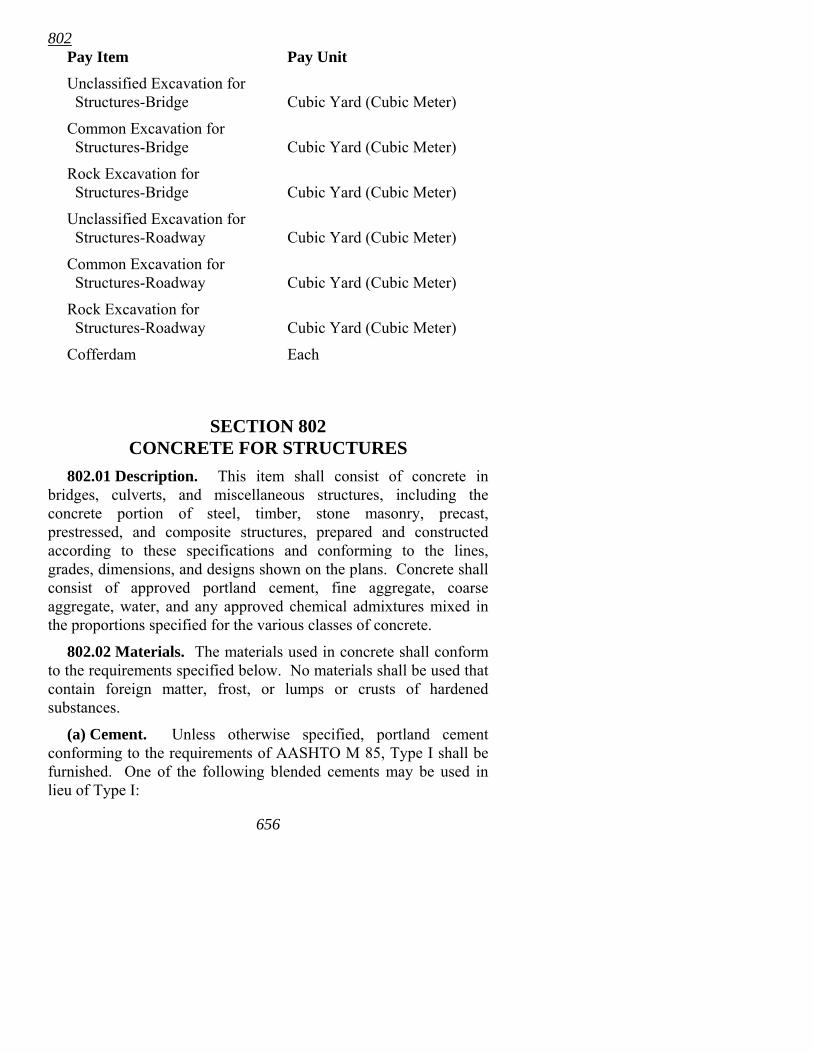
802 Pay Item Pay Unit
Unclassified Excavation for Structures-Bridge Cubic Yard (Cubic Meter)
Common Excavation for Structures-Bridge Cubic Yard (Cubic Meter)
Rock Excavation for Structures-Bridge Cubic Yard (Cubic Meter)
Unclassified Excavation for Structures-Roadway Cubic Yard (Cubic Meter)
Common Excavation for Structures-Roadway Cubic Yard (Cubic Meter)
Rock Excavation for Structures-Roadway Cubic Yard (Cubic Meter)
Cofferdam Each
SECTION 802 CONCRETE FOR STRUCTURES
802.01 Description. This item shall consist of concrete in bridges, culverts, and miscellaneous structures, including the concrete portion of steel, timber, stone masonry, precast, prestressed, and composite structures, prepared and constructed according to these specifications and conforming to the lines, grades, dimensions, and designs shown on the plans. Concrete shall consist of approved portland cement, fine aggregate, coarse aggregate, water, and any approved chemical admixtures mixed in the proportions specified for the various classes of concrete.
802.02 Materials. The materials used in concrete shall conform to the requirements specified below. No materials shall be used that contain foreign matter, frost, or lumps or crusts of hardened substances.
(a) Cement. Unless otherwise specified, portland cement conforming to the requirements of AASHTO M 85, Type I shall be furnished. One of the following blended cements may be used in lieu of Type I:
656
802 • Portland-Pozzolan Cement, AASHTO M 240, Type IP (20%
maximum)
Pozzolan-Modified Portland Cement, AASHTO M 240, Type I (PM)
•
• Slag-Modified Portland Cement, AASHTO M 240, Type I (SM)
Fly ash or ground granulated blast-furnace slag shall not be substituted for blended cements. Cement shall be from sources that are listed on the Department�s Qualified Products List and that have executed a certification agreement with the Department.
Type II cement shall be used for Class B concrete. During the cool season of the year, the Engineer may approve the use of Type I cement in lieu of Type II cement for Class B concrete. Upon approval of the Engineer, Type III cement may be used in the manufacture of prestressed concrete products.
Cement furnished in sacks shall weigh not less than 94 pounds (42.6 kg) per sack.
The mixing or alternate use of cement from different manufacturing plants will not be permitted. The source of cement shall not be changed without the written approval of the Engineer. Cement placed in storage shall be suitably protected. Loss in quality occurring during the storage period will be cause for rejection. If the cement furnished produces erratic results under the field conditions incident to the placing of the concrete, or in regard to the strength of the finished product, or in the time of the initial or final set, the Contractor shall, without notice from the Engineer, cease the use of that source of cement.
(b) Fine Aggregate. The fine aggregate shall consist of clean, hard, durable particles of natural sand or other approved inert material with similar characteristics.
When determined necessary by visual observation, the amount of deleterious substances will be tested by laboratory methods and shall not exceed the following limits:
Maximum Permissible Percent by Weight
Coal and lignite (AASHTO T 113) 0.25 Clay lumps (AHTD Test Method 302) 0.5
657
802 Removed by decantation (AASHTO T 11) 2 Soft and flaky particles (AHTD Test Method 302) 2
All fine aggregate shall be free from injurious amounts of organic impurities.
Aggregates shall be subjected to testing according to AASHTO T 21. Should AASHTO T 21 produce results that indicate that the sand may possibly contain injurious or damaging organic compounds, mortar strength test specimens shall be tested according to AHTD Test Method 530.
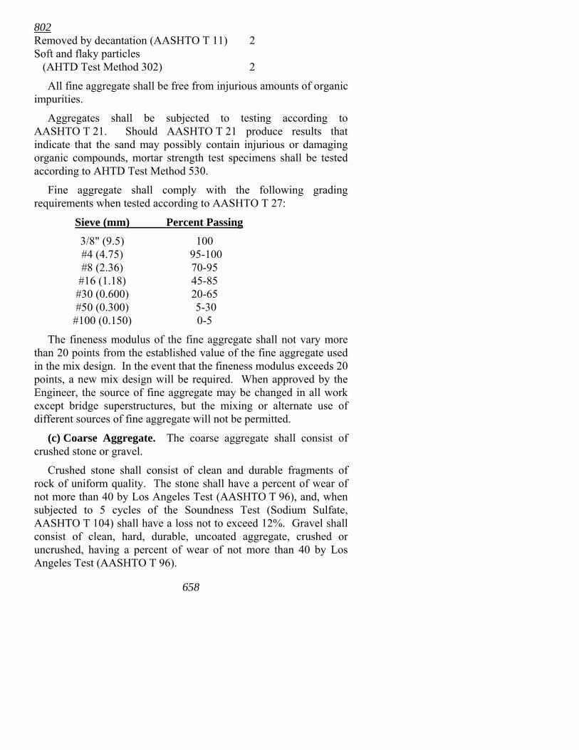
Fine aggregate shall comply with the following grading requirements when tested according to AASHTO T 27:
Sieve (mm) Percent Passing
3/8" (9.5) 100 #4 (4.75) 95-100 #8 (2.36) 70-95 #16 (1.18) 45-85 #30 (0.600) 20-65 #50 (0.300) 5-30 #100 (0.150) 0-5
The fineness modulus of the fine aggregate shall not vary more than 20 points from the established value of the fine aggregate used in the mix design. In the event that the fineness modulus exceeds 20 points, a new mix design will be required. When approved by the Engineer, the source of fine aggregate may be changed in all work except bridge superstructures, but the mixing or alternate use of different sources of fine aggregate will not be permitted.
(c) Coarse Aggregate. The coarse aggregate shall consist of crushed stone or gravel.
Crushed stone shall consist of clean and durable fragments of rock of uniform quality. The stone shall have a percent of wear of not more than 40 by Los Angeles Test (AASHTO T 96), and, when subjected to 5 cycles of the Soundness Test (Sodium Sulfate, AASHTO T 104) shall have a loss not to exceed 12%. Gravel shall consist of clean, hard, durable, uncoated aggregate, crushed or uncrushed, having a percent of wear of not more than 40 by Los Angeles Test (AASHTO T 96).
658
802 When determined necessary by visual observation, the amount of
deleterious substances will be tested by laboratory methods and will not exceed the following limits:
Maximum Permissible Percent by Weight
Coal and lignite (AASHTO T 113) 0.25 Clay lumps (AHTD Test Method 302) 0.25 Soft Fragments (AHTD Test Method 302) 5 Total deleterious substances 5 Removed by decantation (AASHTO T 11) 1
The maximum percentage by weight removed by decantation (AASHTO T 11) from crushed stone coarse aggregate may be increased to 1.5% provided the percent loss (AASHTO T 11) from the fine aggregate does not exceed 1.0% or to 1.8% provided the percent loss from the fine aggregate does not exceed 0.5%.
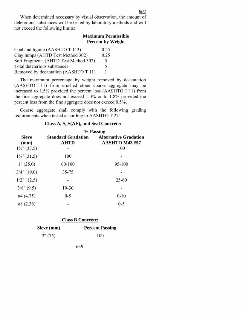
Coarse aggregate shall comply with the following grading requirements when tested according to AASHTO T 27:
Class A, S, S(AE), and Seal Concrete:
% Passing Sieve (mm)
Standard Gradation AHTD
Alternative Gradation AASHTO M43 #57
1½" (37.5) - 100
1¼" (31.5) 100 -
1" (25.0) 60-100 95-100
3/4" (19.0) 35-75 -
1/2" (12.5) - 25-60
3/8" (9.5) 10-30 -
#4 (4.75) 0-5 0-10
#8 (2.36) - 0-5
Class B Concrete:
Sieve (mm) Percent Passing
3" (75) 100
659
802 1¼" (31.5) 35-65 3/4" (19.0) 15-40 #4 (4.75) 0-5
The fineness modulus of the coarse aggregate shall not vary more than 20 points from the established value of the coarse aggregate used in the mix design. In the event that the fineness modulus exceeds 20 points, a new mix design will be required. When approved by the Engineer, the source of coarse aggregate may be changed in all work except bridge superstructures, but the mixing or alternate use of different sources of coarse aggregate will not be permitted.
(d) Water. Water used in mixing or curing shall be clean and free from injurious amounts of oil, salts, or other deleterious substances, and shall not contain more than 1000 ppm of chlorides.
Water from municipal supplies approved by the State Health Department will not require testing but water from other sources shall be sampled and tested before use in concrete.
Tests will be made according to AASHTO T 26.
Where the source of water is relatively shallow, it shall be maintained at such depth and the intake so enclosed as to exclude silt, mud, grass, or other foreign materials.
(e) Admixtures. (1) General. Admixtures shall be used to improve certain characteristics of the concrete when specified on the plans or may be used when requested by the Contractor and approval is given by the Engineer. The Contractor's request shall be supported with the manufacturer's certified formulation of the proposed admixture and with sufficient evidence that the proposed admixture has given satisfactory results on other similar work. Permission to use the admixture may be withdrawn at any time by the Engineer when satisfactory results are not being obtained.
Admixtures shall be approved by the Engineer. Admixtures shall be compatible with each other, as advised by the manufacturer. The admixture dosage rate range as recommended by the manufacturer shall be used. Should the dosage rate for any admixture not yield desirable characteristics in the concrete, the dosage of admixture used shall be based on test results obtained by trial batches.
660
802 Admixtures shall be added to the mixing water by means of a
mechanical dispenser that will accurately meter the additive throughout the mix water cycle. The dispenser shall be constructed and connected so that the amount of admixture entering the mixing water can be readily determined.
(2) Air Entraining Agent. Air entraining agent shall comply with the requirements of AASHTO M 154 and be approved by the Engineer. Permission to use the agent may be withdrawn at any time by the Engineer when satisfactory results are not being obtained.
(3) Retarding Agent. In order to permit the retarding of the set and extend the finishing time of concrete, a retarding agent shall be used when specified on the plans or may be used when permission for its use is requested by the Contractor and such permission is given by the Engineer. The retarding agent shall be a Type B or Type D admixture as defined in AASHTO M 194. Permission to use the agent may be withdrawn at any time by the Engineer when satisfactory results are not being obtained.
The agent shall be free of chlorides. When air-entrained concrete is specified, the air-entraining agent and the retarding agent shall be so incorporated that the air content of the concrete shall fall within the percentage range stipulated in the specifications. When air-entrained concrete is not specified, the concrete to which the retarding agent has been added shall have an air content not greater than 3 percent.
No compensation will be made for furnishing and incorporating the agent in the mix. No additional compensation will be made for furnishing, placing, finishing, and curing the concrete involved.
(4) Other Admixtures. The use of other admixtures will be considered by the Engineer on a case by case basis upon written request from the Contractor. When admixture(s) affecting the slump of the plastic concrete are approved by the Department, the Department may, upon request of the Contractor, modify the concrete slump requirements for that concrete utilizing this approved additive. If approved, the admixture used shall be furnished at no additional cost to the Department. Permission to use an admixture may be withdrawn at any time by the Engineer when satisfactory results are not being obtained.
661
802 (f) Fly Ash. Fly ash used in concrete shall meet the requirements
of AASHTO M 295, Class C or F. Mixing of Class C and Class F fly ashes will not be permitted.
(g) Ground Granulated Blast-Furnace Slag. Ground granulated blast-furnace slag used in concrete shall meet the requirements of AASHTO M 302, Grade 100 or higher.
802.03 Handling and Storage of Materials. The handling and storage of concrete aggregates shall be such as to prevent segregation and contamination with foreign materials.
Coarse and fine aggregates shall be separated by bulkheads or stored in separate stockpiles sufficiently removed from each other to prevent the material at the edges of the piles from becoming intermixed. Coarse aggregate stockpiles not confined by bulkheads or bins shall be built up in layers not to exceed 4' (1.2 m) in height and each layer shall be completely in place before beginning the next. Coning or building up of stockpiles by depositing material in one place will not be permitted. In order to control the gradation of the large aggregate for Class B concrete, it may be necessary that the Contractor stockpile the aggregate in two or more gradation ranges, blending by weight as required to obtain the specified gradation.
There shall be adequate aggregate stockpiled to allow representative sampling sufficiently in advance of any placement to determine its acceptability, with the minimum amount being that required to adequately complete the planned placement.
Cement shall be stored in suitable weather-proof buildings or silos that will protect the cement from dampness. Provision for storage shall be ample and the shipments of cement as received shall be separately stored in such a manner as to provide easy access for the identification and inspection of each shipment. Stored cement shall meet the test requirements at any time after storage when a re-test is ordered by the Engineer.
On small jobs, storage in the open may be permitted by written authorization from the Engineer, in which case a raised platform and ample waterproof covering shall be provided.
802.04 Classes of Concrete. The appropriate class of concrete shall be used in the part of the structure as specified or where designated by the Engineer. The classes are as follows: 662
802 Non Air-entrained Air-entrained Miscellaneous Concrete Concrete Concrete
Class A Class S(AE) Class M Class B Class S Seal
The following requirements shall govern unless otherwise shown on the plans:
Class A concrete shall be used in wingwalls and miscellaneous construction.
Class B concrete shall be used in mass concrete.
Class S or S(AE) concrete shall be used in retaining walls, box culverts, footings, piers, bents, columns, abutments, and superstructures, including girders, beams, floor slabs, and parapet walls.
Seal concrete shall be used for concrete deposited under water.
Class M concrete shall be used in miscellaneous construction as specified in Sections 500, 600, and 700.
Class S(AE) may be substituted for Class S. Class S(AE), Class S or paving concrete under Section 501 may be substituted for Class A. Acceptance criteria for strength, water/cement ratio, and slump shall be that of the Class specified. Different classes of concrete shall not be mixed in the same continuous placement.
When Class M concrete is specified, the Contractor may use any commercially produced concrete mix or an approved Class A, S, S(AE), or paving concrete under Section 501. Unless otherwise specified, bagged commercial concrete mix may not be used for Class M concrete. For acceptance purposes, the minimum strength, maximum water/cement ratio, and maximum slump shall be that specified for Class A concrete. For small placements (approximately 1 cubic yard m [ 1 cu m] or less), the concrete may be mixed on site using a portable mixer. The size of each batch shall not exceed 80% of the manufacturer's rated capacity of the mixer. When mixing on site, and with the prior approval of the Engineer, the materials for each batch may be measured by volume by converting the mix design weights of each material to equivalent volumes. 663
802 802.05 Mix Design. (a)General. The concrete mixture shall be
proportioned to ensure a workable and durable concrete for the various classes, as specified in Table 802-1.
The Engineer will not perform any pre-bid testing of materials. It will be the Contractor�s responsibility to locate acceptable material sources unless the sources are so noted in the plans or Special Provisions.
(b) Mix Design by the Contractor. The proportions to be used in the mix for each class shall be determined by the Contractor using the absolute volume method. The Contractor may use the procedure provided in the ACI Standard 211.1, modified to comply with the minimum cement content and maximum water/cement ratio specified for the class of concrete. Prior to the start of production of the concrete mixture, the Contractor shall submit test results and/or certifications for all materials and detailed mix design data to the Engineer for review. Aggregate, fly ash, and ground granulated blast-furnance slag (GGBFS) material properties used in the mix design shall be representative of the exact materials proposed for use. The testing source (commercial laboratory, qualified technician, AHTD provided data, etc.) and the date of the test shall be provided. The specific plant sources for the cement, fly ash or GGBFS, and aggregates shall be shown on the mix design. The documentation submitted with the mix design shall specify which procedure was used and whether oven dry or saturated surface dry weights were used in the calculations. The mix design shall specify the quantity of each component of the mix, including all authorized additives. Acceptance of the mix design by the Engineer will be based on apparent conformity to the requirements shown in Table 802-1. If the mix design fails to produce acceptable results or if there is a change in the aggregates, fly ash, or cement being used, a new mix design will be required. It shall remain the Contractor�s responsibility during production to produce concrete conforming to the mix design and the minimum acceptance criteria specified. When requested by the Engineer, the Contractor shall submit samples of all materials for verification testing. Production shall not begin until the mix design is accepted by the Engineer.
664
802
665
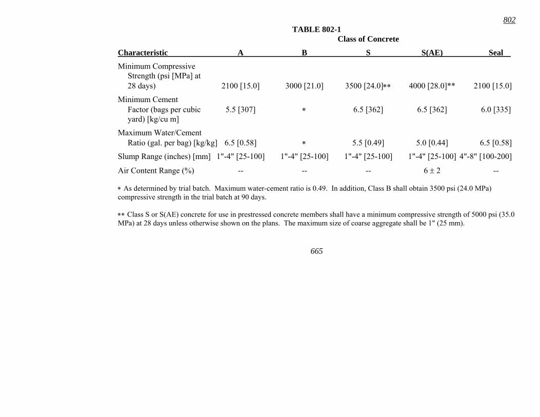
TABLE 802-1 Class of Concrete
Characteristic A B S S(AE) Seal
Minimum Compressive Strength (psi [MPa] at 28 days) 2100 [15.0] 3000 [21.0] 3500 [24.0]∗∗ 4000 [28.0]** 2100 [15.0]
Minimum Cement Factor (bags per cubic 5.5 [307] ∗ 6.5 [362] 6.5 [362] 6.0 [335] yard) [kg/cu m]
Maximum Water/Cement Ratio (gal. per bag) [kg/kg] 6.5 [0.58] ∗ 5.5 [0.49] 5.0 [0.44] 6.5 [0.58]
Slump Range (inches) [mm] 1"-4" [25-100] 1"-4" [25-100] 1"-4" [25-100] 1"-4" [25-100] 4"-8" [100-200]
Air Content Range (%) -- -- -- 6 ± 2 --
∗ As determined by trial batch. Maximum water-cement ratio is 0.49. In addition, Class B shall obtain 3500 psi (24.0 MPa) compressive strength in the trial batch at 90 days.
∗∗ Class S or S(AE) concrete for use in prestressed concrete members shall have a minimum compressive strength of 5000 psi (35.0 MPa) at 28 days unless otherwise shown on the plans. The maximum size of coarse aggregate shall be 1" (25 mm).
802
66
A mix design submitted for acceptance need not be prepared specifically for this project, but may be a previously accepted design that uses the same materials and meets the same design criteria.
Mix designs accepted under this section will become the property of the Department and may be accepted for use on other projects, by other contractors, or by the Department.
(c) Trial Batches. Mix designs proposed by the Contractor for all Class S(AE) and Class B concretes shall be tested by trial batches using the specific materials, including admixtures, that are intended for use on the job. The Contractor shall prepare a plant batch of at least 2 cubic yards (1.5 cu m) or one-third the rated capacity of the mixer, whichever is greater. In lieu of the plant batch, the Contractor may prepare trial batches in a laboratory according to AASHTO T 126. These trial batches shall be accomplished by the Contractor under the observation of the Engineer. Sampling and testing will be conducted by the Engineer. These batches shall be sampled and tested for compliance with the specifications for slump, air content, and compressive strength.
In lieu of the above procedure, the Contractor may retain an approved independent laboratory or a Registered Professional Engineer to prepare and test trial batches. In this case, trial batch information and laboratory results shall be furnished to the Engineer along with a statement certifying that the testing was performed according to the specifications.
For Class S(AE) concrete the air-entrainment shall be accomplished by adding to the mixing water the proper amount of air-entraining agent in solution. The Contractor shall determine the amount of admixture required to produce an air content within the range specified. The amount of air entraining agent shall be adjusted by the Contractor during production as necessary to keep the air content within the range specified. A mix design may be approved with respect to compressive strength when at least two test cylinders show the minimum required strength value at any age between 7 days and 28 days, inclusive.
6
For Class B concrete, the mix design shall produce a workable and durable concrete meeting the minimum strength requirements specified in Table 802-1 and shall have a low heat of hydration when placed in large quantities. Fly ash conforming to AASHTO M295 may be substituted for a part of the Type II Cement not to
802
66
exceed 120 pounds per cubic yard (70 kg/cu m) of concrete, and shall be included in the calculation of the water/cement ratio. Ninety-day test specimens will be required for Class B trial batches. For construction purposes, the sampling and testing will comply with standard procedures for sampling and testing.
All trial batches required by these specifications or developed at the option of the Contractor shall be accomplished by the Contractor and shall be subject to the review and approval of the Engineer.
Concrete from the trial batch may be used in miscellaneous construction subject to the approval of the Engineer and further provided that the minimum compressive strength specified for the construction in which the concrete is used is attained. If the required compressive strength is not attained, the Contractor shall remove the concrete and replace it with acceptable concrete at no cost to the Department.
(d) Fly Ash. Fly ash may be used as a partial replacement for Type I cement, not exceeding 20% by weight, in all classes of concrete except Class B. Substitution shall be made at the rate of one pound (kilogram) of fly ash for each pound (kilogram) of cement replaced. The water/cement ratio shall be calculated using the total weight of both cement and fly ash. Fly ash in Class B concrete shall meet the requirements specified in Subsection 802.05(c). Mixtures with fly ash shall meet the same requirements as mixtures without fly ash. Fly ash will not be allowed as a substitute for high early strength or blended cements. Class F fly ash shall not be used in bridge deck concrete placed between October 15 and April 1. When fly ash is used, the total weight of both cement and fly ash will be used in design calculations.
When the Contractor elects to use fly ash as a partial replacement for the cement in Class S or Class S(AE) concrete, the proposed mix design shall be tested by the preparation and testing of trial batches according to Subsection 802.05(c). Trial batches will not be required for Class A concrete.
(e) Ground Granulated Blast-Furnace Slag. Ground granulated blast-furnace slag (GGBFS) may be used as a partial replacement, not exceeding 25% by weight, for Type I cement, in all classes of concrete except high early strength and seal. Substitution shall be made at the rate of one pound (kilogram) of GGBFS for
7
802
668
each pound (kilogram) of cement replaced. GGBFS will not be allowed with high early strength or blended cements.
When the Contractor elects to use GGBFS as a partial replacement for the cement in Class S or Class S(AE) concrete, the proposed mix design shall be tested using trial batches according to 802.05(c). Trial batches will not be required for Class A concrete.
802.06 Quality Control, Acceptance, and Adjustments in Payments. (a) Quality Control by the Contractor. The Contractor shall be responsible for quality control of materials during handling, blending, mixing, transporting, and placement operations, and for necessary adjustments in proportioning of materials used to produce the specified concrete.
The Contractor shall be responsible for determining gradation and moisture content of fine and coarse aggregates used in the concrete mixture and for testing the mixture for air content, slump, and compressive strength. The Contractor shall determine the specific locations for samples and frequency of sampling for quality control, except the minimum frequency which is listed below for aggregate gradation shall be used. In addition, the Contractor shall be required to perform acceptance sampling and testing at specific times and/or locations specified by the Engineer according to Subsection 802.06(b).
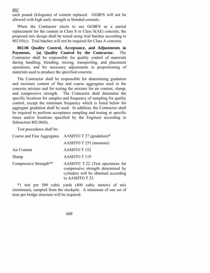
Test procedures shall be:
Coarse and Fine Aggregates AASHTO T 27 (gradation)*
AASHTO T 255 (moisture)
Air Content AASHTO T 152
Slump AASHTO T 119
Compressive Strength** AASHTO T 22 (Test specimens for compressive strength determined by cylinders will be obtained according to AASHTO T 23.
*1 test per 500 cubic yards (400 cubic meters) of mix (minimum), sampled from the stockpile. A minimum of one set of tests per bridge structure will be required.
802
669
**A minimum of two (2) cylinders shall be cast and tested. Results will be based upon the average result from the two cylinders.
An adequate supply of aggregate must be stockpiled to allow representative sampling in advance of any placement, with the minimum amount being that required to complete the day�s planned placement. The initial quality control test results for gradation must be completed and the test results submitted to the Engineer prior to the beginning of mix production of each class of concrete. Subsequent tests shall be taken and tested during production, and the test reports submitted to the Engineer by the end of the next business day after the sample is taken. Any failing gradation test result will result in halting production. The aggregate remaining in the stockpile will be resampled and tested by the Contractor and the Engineer. If the test results indicate that the aggregate is outside of the specification limits in Subsection 802.02, the stockpile shall either be corrected or replaced. Passing test reports must be submitted to the Engineer before work resumes.
The Contractor shall furnish all personnel, equipment, and facilities necessary to perform the required sampling and testing. The Contractor�s facilities shall be separate from any Field Laboratory and/or Field Office furnished to the Department under the Contract. Quality control sampling and testing by the Contractor shall be performed in a qualified laboratory by a certified technician. Requirements for technician certification and laboratory qualification are contained in the Department�s Manual of Field Sampling and Testing Procedures. The Contractor shall maintain records of all samples taken and the results of all tests performed. Test reports shall be signed and copies made available to the Engineer if requested.
The Contractor shall certify to the Engineer that the calibration of the concrete cylinder compression testing machine has been verified. This verification shall be performed in accordance with AASHTO T 22 and T 67 under any of the following conditions and documented in accordance with AASHTO T 67:
1. After an elapsed interval of 18 months (maximum) since the previous calibration.
2. After original installation of the machine or following relocation of the machine.
802
670
3. Immediately after repairs or adjustments.
4. Whenever there is a reason to doubt the accuracy of the results, without regard to the time interval since the last verification.
If the Contractor desires additional compressive strength tests to be used for scheduling purposes or to determine the time for stripping forms or loading the structure, such tests will be performed by the Contractor at no cost to the Department.
The Contractor shall provide an opportunity for the Engineer to observe all quality control sampling and testing procedures. The Contractor shall split samples with the Department when requested. The Contractor shall be required to make changes to the equipment and/or procedures if this testing or additional testing by the Department does not verify the Contractor�s test results.
When individual gradation, slump, or air content measurements fall outside tolerance limits, the Contractor shall immediately make adjustments to bring the mixture within specified limits. If the Contractor fails to make proper adjustments, or if the mix is obviously defective, operations shall cease. Operations shall not resume until proper adjustments have been made.
(b) Acceptance Testing. Acceptance sampling and testing by the Contractor will be based upon lots. The lot sizes shall be determined as follows:
Slump, Air Content, and Compressive Strength: The standard lot size for acceptance of slump, air content, and compressive strength of concrete will be 400 cubic yards (300 cubic meters) of mix, with each standard lot divided into four sublots of 100 cubic yards (75 cubic meters). In addition, for Class S(AE) concrete the maximum sublot size will be 100 cubic yards (75 cubic meters) or one deck pour, whichever is less. Partial lots, of any size, may be established by the Engineer at any time. A minimum of one set of tests per bridge structure will be required. The minimum frequency for acceptance of slump, air content, and compressive strength by the Contractor shall be one set of tests for each sublot of each class of concrete. The Contractor shall obtain and test one sample taken at random from each sublot. All samples of the mixture to be tested for air content, slump, and compressive strength shall be taken from one
802
671
location. The Department will determine the location for each sample in the sublot by AHTD Test Method 465.
Test methods for acceptance shall be the same as specified for quality control testing. Acceptance sampling and testing by the Contractor shall be performed in a qualified laboratory by a certified technician. Requirements for technician certification and laboratory qualification are contained in the Department�s Manual of Field Sampling and Testing Procedures. The Contractor shall provide an opportunity for the Engineer to observe all acceptance sampling and testing procedures.
The Contractor�s acceptance sampling and testing procedures, equipment, and results will be subject to independent assurance sampling and testing conducted by the Department. Independent assurance sampling and testing will be conducted at the frequencies indicated in the Department�s Manual of Field Sampling and Testing Procedures. The Contractor shall be required to make changes to the equipment and/or procedures used if the results of the independent assurance tests do not correlate with the Contractor�s test results.
Acceptance sampling and testing shall be accomplished in a timely manner. The Contractor shall maintain records of all samples taken and the results of all tests performed. Signed copies of these records shall be furnished to the Engineer for inclusion in the project files within one business day of the day that the tests are performed. The item of work being tested shall not be considered complete or accepted until test reports for all materials are submitted to the Engineer.
The Department will obtain and test a minimum of one sample taken at random from each lot, including partial lots, to be used both for verification and for acceptance. The location of the lot sample will be determined by AHTD Test Method 465. Verification testing for compressive strength will be by casting and testing cylinders and/or drilling and testing cores. Verification testing will be conducted in accordance with Subsection 106.11 and the Manual of Field Sampling and Testing Procedures.
The Department will perform all testing required for water, cement, fly ash, soundness and Los Angeles wear of aggregates.
802
672
(c) Acceptance and Adjustments in Payments. Acceptance and adjustment in payments will be by lot. Acceptance of a standard lot will be based on the average results of the tests performed on the lot. The average result will include the sublot results of tests performed by the Contractor and the results of the test performed by the Department.
In the event that the compressive strengths of the test specimens in a sublot are below the specified value in Table 802-1, the Department will conduct an investigation to determine the structural adequacy of the concrete. If this investigation determines that the concrete in question is acceptable, then price adjustments will be calculated according to Table 802-2. Table 802-2 lists test properties for acceptance, price reduction, and rejection limits.
When test results for a lot fall within the limits shown in Table 802-2 as �Compliance Limits�, the concrete shall be accepted with no price reduction. If test results for a lot for any single property falls within the limits shown as �Price Reduction Limits�, the failing material may be left in place at a reduced price. If test results for a lot for any single property falls within the limits shown as �Rejection Limits�, the failing material shall be removed and replaced at no cost to the Department. The percent the bid price shall be reduced for a lot not meeting the �Compliance Limits� for both Air Content and Compressive Strength will be determined by adding the price reduction percentages contained in Table 802-2.
In the sublot containing the Department�s lot test, if the result of either the Contractor�s sublot test or the Department�s lot test falls outside the �Compliance Limits�, the two tests will be averaged and the average will be used to determine acceptance or rejection.
At the Contractor�s option, additional testing for confirming price reductions or rejection due to compressive strength results may be performed by the Contractor at locations determined by the Department. In such cases three cores shall be taken in each sublot containing compressive strength results not in �Compliance Limits�. The compressive strength shall be determined by the average result of the cores. Cores shall be taken according to AASHTO T 24. The average of the three cores must meet or exceed applicable price reduction limits or rejection limits. Acceptance and pay adjustments will then be determined based on these results.
802
673
When two consecutive lots or any three out of five consecutive lots fail to qualify for full payment, work will be stopped until corrective action is taken.
Continuous production of concrete not qualifying for full payment will not be allowed.
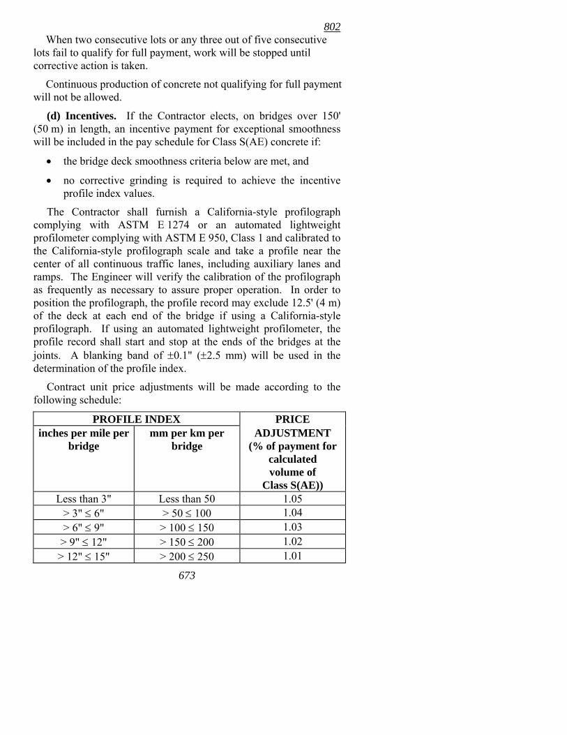
(d) Incentives. If the Contractor elects, on bridges over 150' (50 m) in length, an incentive payment for exceptional smoothness will be included in the pay schedule for Class S(AE) concrete if:
• the bridge deck smoothness criteria below are met, and
• no corrective grinding is required to achieve the incentive profile index values.
The Contractor shall furnish a California-style profilograph complying with ASTM E 1274 or an automated lightweight profilometer complying with ASTM E 950, Class 1 and calibrated to the California-style profilograph scale and take a profile near the center of all continuous traffic lanes, including auxiliary lanes and ramps. The Engineer will verify the calibration of the profilograph as frequently as necessary to assure proper operation. In order to position the profilograph, the profile record may exclude 12.5' (4 m) of the deck at each end of the bridge if using a California-style profilograph. If using an automated lightweight profilometer, the profile record shall start and stop at the ends of the bridges at the joints. A blanking band of ±0.1" (±2.5 mm) will be used in the determination of the profile index.
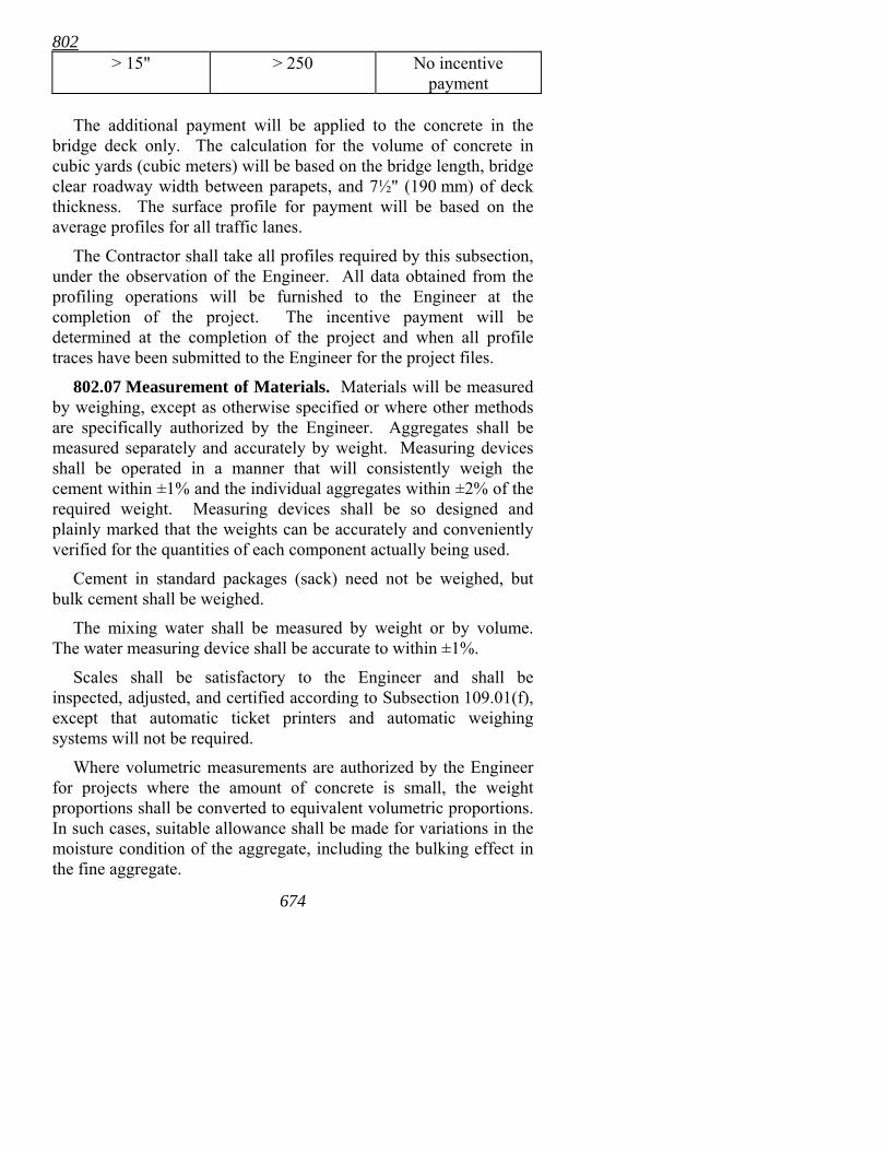
Contract unit price adjustments will be made according to the following schedule:
PROFILE INDEX PRICE inches per mile per
bridge mm per km per
bridge ADJUSTMENT
(% of payment for calculated volume of
Class S(AE)) Less than 3" Less than 50 1.05
> 3" ≤ 6" > 50 ≤ 100 1.04 > 6" ≤ 9" > 100 ≤ 150 1.03 > 9" ≤ 12" > 150 ≤ 200 1.02
> 12" ≤ 15" > 200 ≤ 250 1.01
802
674
> 15" > 250 No incentive payment
The additional payment will be applied to the concrete in the
bridge deck only. The calculation for the volume of concrete in cubic yards (cubic meters) will be based on the bridge length, bridge clear roadway width between parapets, and 7½" (190 mm) of deck thickness. The surface profile for payment will be based on the average profiles for all traffic lanes.
The Contractor shall take all profiles required by this subsection, under the observation of the Engineer. All data obtained from the profiling operations will be furnished to the Engineer at the completion of the project. The incentive payment will be determined at the completion of the project and when all profile traces have been submitted to the Engineer for the project files.
802.07 Measurement of Materials. Materials will be measured by weighing, except as otherwise specified or where other methods are specifically authorized by the Engineer. Aggregates shall be measured separately and accurately by weight. Measuring devices shall be operated in a manner that will consistently weigh the cement within ±1% and the individual aggregates within ±2% of the required weight. Measuring devices shall be so designed and plainly marked that the weights can be accurately and conveniently verified for the quantities of each component actually being used.
Cement in standard packages (sack) need not be weighed, but bulk cement shall be weighed.
The mixing water shall be measured by weight or by volume. The water measuring device shall be accurate to within ±1%.
Scales shall be satisfactory to the Engineer and shall be inspected, adjusted, and certified according to Subsection 109.01(f), except that automatic ticket printers and automatic weighing systems will not be required.
Where volumetric measurements are authorized by the Engineer for projects where the amount of concrete is small, the weight proportions shall be converted to equivalent volumetric proportions. In such cases, suitable allowance shall be made for variations in the moisture condition of the aggregate, including the bulking effect in the fine aggregate.
802
675
Representative samples shall be taken and the moisture content determined for each kind of aggregate. When the aggregates contain more water than the quantity necessary to produce a saturated surface-dry condition, the batch weights for aggregates and water shall be adjusted accordingly.
802.08 Mixing Concrete. Concrete shall be thoroughly mixed in a mixer of an approved size and type that will ensure a uniform distribution of the materials throughout the mass.
The concrete shall be mixed only in the quantity required for immediate use. Concrete that has developed an initial set shall not be used. Re-tempering concrete will not be permitted.
Concrete may be proportioned and mixed in a stationary central plant and hauled to the point of delivery in agitator trucks of approved type or in non-agitating equipment, when approved by the Engineer; proportioned in a stationary central plant and mixed in approved transit mix trucks enroute to the point of delivery; or mixed completely in transit mix trucks at the point of delivery, following the addition of mixing water.
The Engineer shall be furnished the manufacturer's rated capacity of each mixer and agitator, along with the recommended speed of rotation for the various uses of each mixer. Truck mixers and agitators shall be equipped with means by which the number of revolutions of the drum, blades, or paddles may be readily verified.
Mixers and agitators shall not be charged in excess of the manufacturer's rated capacity. Concrete shall be delivered and discharged from the truck mixer or agitator into the forms within 1½ hours after the introduction of the mixing water to the cement. In hot weather, or under other conditions contributing to quick setting of the concrete, the maximum allowable time may be reduced by the Engineer. Each batch shall be accompanied by a time slip issued at the batch plant.
Plants and transit mix trucks shall be equipped with adequate water storage and a device for accurately measuring and controlling the amount of water used in each batch. When a stationary mixer is used, a mechanical means shall be provided for automatically preventing the discharge of the mixer until the materials have been mixed for a period of not less than one minute.
802
67
Truck mixers shall be capable of combining the ingredients of the concrete into a thoroughly mixed and uniform mass, and of discharging the concrete within the specified range of consistency. The concrete shall be mixed not less than 70 nor more than 100 revolutions of the drum or blades at the rate of rotation specified by the manufacturer as the mixing speed. The pick-up and throw-over blades in the drum of all mixers shall be maintained in satisfactory condition to assure thoroughly mixed concrete.
Agitators shall be capable of maintaining the concrete in a thoroughly mixed and uniform mass and of discharging the concrete within the specified range of consistency.
When approved in writing by the Engineer, concrete may be transported in approved non-agitating equipment. Bodies of this equipment shall be smooth, watertight, metal containers equipped with gates that will permit control of the discharge of the concrete. Covers shall be provided for protection against the weather. The concrete shall be delivered in a thoroughly mixed and uniform mass and discharged within the specified range of consistency. Placement in forms shall be completed within 30 minutes after introduction of the mixing water to the cement.
Concrete shall be mixed according to the mixer manufacturer's specifications in order to obtain an acceptable mass of concrete. During the period of mixing, the mixer shall operate at the manufacturer's recommended mixing speed. Additional mixing, if any, shall be at the speed designated by the manufacturer of the equipment as agitating speed.
If additional mixing water is required to maintain the specified slump, and is added with the permission of the Engineer, approximately 20 revolutions of the mixer drum at mixing speed shall be required before discharge of any concrete.
6
67
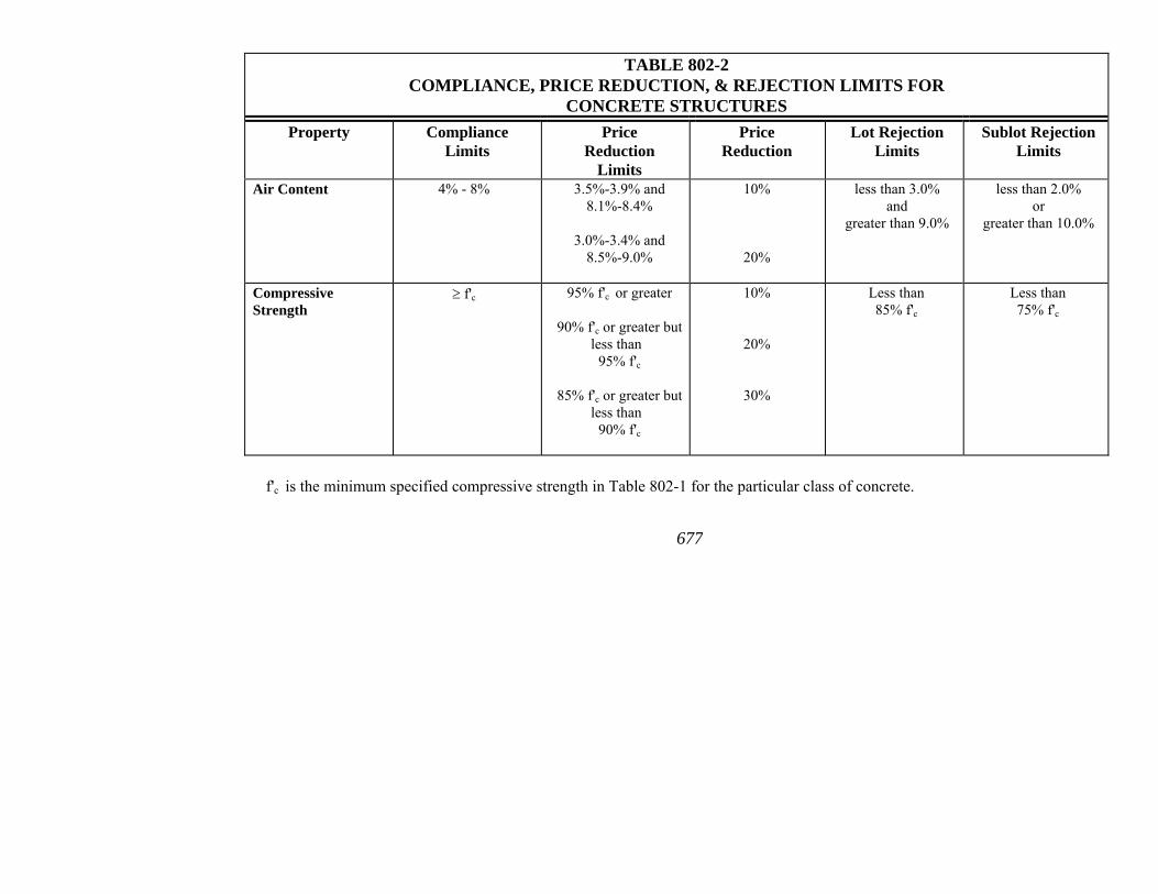
TABLE 802-2 COMPLIANCE, PRICE REDUCTION, & REJECTION LIMITS FOR
CONCRETE STRUCTURES Property Compliance
Limits Price
Reduction Limits
Price Reduction
Lot Rejection Limits
Sublot Rejection Limits
Air Content 4% - 8% 3.5%-3.9% and
8.1%-8.4%
3.0%-3.4% and 8.5%-9.0%
10%
20%
less than 3.0% and
greater than 9.0%
less than 2.0% or
greater than 10.0%
Compressive Strength
≥ f'c 95% f'c or greater
90% f'c or greater but less than
95% f'c
85% f'c or greater but less than
90% f'c
10%
20%
30%
Less than 85% f'c
Less than 75% f'c
f'c is the minimum specified compressive strength in Table 802-1 for the particular class of concrete.
7
802
678
When a quality control sample for air content, taken within the allowable time limits for discharge of the concrete and prior to discharge for placement, shows an air content below the specified level by more than the allowable tolerance shown in Table 802-2, the Contractor may use additional air-entraining admixture to achieve the desired air content. The air-entraining agent and water shall be mixed in a separate container, and the mixed solution added to the truck mixer and mixed for a minimum of 30 revolutions at the mixing speed. A second air content test shall then be taken to determine if the air content is now within the allowable limits.
The entire contents of the mixer, including wash water, shall be removed from the drum before the addition of materials for a succeeding batch.
There shall be sufficient capacity and transporting equipment to ensure continuous concrete delivery at the rate required.
If the concrete furnished produces erratic results relative to consistency, strength, or time of initial or final set, the Contractor shall cease the use of that concrete until corrections are made to ensure work of the specified quality.
802.09 Handling and Placing Concrete. (a) General. The Contractor shall provide sufficient supervision, manpower, equipment, tools, and materials and shall assure proper production, delivery, placement, and finishing of the concrete for each placement according to the specifications. Unless otherwise specified, concrete shall be placed continuously between authorized construction and/or expansion joints, subject to the time limits and placement rates specified below.
The time interval between batches of concrete shall not exceed 20 minutes. Unless otherwise specified, the minimum placement rate shall be 20 cubic yards per hour (15 cu m/h).
Any placement that does not produce results that conform to the specifications shall be repaired or replaced, as required, at no cost to the Department. Further placements of a similar nature and size will not be permitted until corrective measures have been taken to assure compliance with the specifications.
The minimum placement rate shall not apply to concrete other than bridges, box culverts, and retaining walls, but the interval between batches shall not exceed 20 minutes.
802
679
In preparation for the placing of concrete, construction debris and extraneous matter shall be removed from the interior of forms. Struts, stays, and braces, serving temporarily to hold the forms in correct shape and alignment pending the placing of concrete, shall be removed when the concrete placement has reached an elevation rendering their service unnecessary.
(1) Conveying. Concrete shall be placed to avoid segregation of the materials and the displacement of the reinforcement. The use of long troughs, chutes, and pipes for conveying the concrete to the forms will be permitted only when authorized by the Engineer. In case an inferior quality of concrete is produced by the use of such conveyors, the Contractor shall, without notice from the Engineer, cease the use of that conveyor until such corrections in procedure are made to ensure work of the quality specified.
Open troughs and chutes shall be of metal or metal lined. Where steep slopes are required, the chutes shall be equipped with baffles or be in short lengths that reverse the direction of movement. Aluminum chutes, troughs, and pipes shall not be used for depositing concrete.
Chutes, troughs, and pipes shall be kept clean and free from coatings of hardened concrete by thoroughly flushing with water after each run. Water used for flushing shall be discharged clear of the structure.
When placing operations involve dropping the concrete more than 5' (1.5 m), it shall be deposited through approved pipes. Walls of 10" (250 mm) thickness or less may be placed without the use of pipes, provided the concrete can be placed without segregation.
(2) Placing. Concrete shall be placed in horizontal layers not more than 18" (0.5 m) thick except as hereinafter provided. When less than a complete layer is placed, it shall be terminated in a vertical bulkhead. Each layer shall be placed and consolidated before the preceding batch has taken initial set to prevent injury to the concrete and avoid surfaces of separation between the batches. Each layer shall be consolidated so as to avoid the formation of a construction joint with a preceding layer that has not taken initial set.
Concrete in footings shall be placed in the dry unless natural conditions prohibit. In that case, concrete shall be placed according
802
680
to Subsections 801.05 and/or 801.06, as appropriate. In order to separate water from the concrete, it will be permissible to utilize polyethylene sheeting or tarpaulins to maintain a physical barrier between the water and the concrete.
When the placing of concrete is temporarily discontinued, the concrete, after becoming firm enough to retain its form, shall be cleaned of laitance and other objectionable material to a sufficient depth to expose sound concrete. To avoid visible joints as far as possible upon exposed faces, the top surface of the concrete adjacent to the forms shall be smoothed with a trowel. Where a "feather edge" might be produced at a construction joint, an inset form shall be used to produce an edge thickness of not less than 6" (150 mm).
Immediately following the discontinuance of placing concrete, accumulations of mortar splashed upon the reinforcing steel and the surfaces of forms should be removed. Dried mortar chips and dust shall not be puddled into the concrete. If the accumulations are not removed prior to the concrete becoming set, care shall be exercised not to damage or break the concrete-steel bond at or near the surface of the concrete while cleaning reinforcing steel.
After initial set of the concrete, the forms shall not be jarred and no strain shall be placed on the ends of projecting reinforcing bars.
(3) Consolidating. All concrete, except seal concrete, during and immediately after depositing shall be thoroughly consolidated. This shall be accomplished by mechanical vibration subject to the following provisions:
a. The vibration shall be internal unless special authorization of other methods is given by the Engineer.
b. Vibrators shall be of a type and design approved by the Engineer. They shall be capable of transmitting vibration to the concrete at rated frequencies of not less than 4500 impulses per minute.
c. The intensity of vibration shall be such as to visibly affect a mass of concrete over a radius of at least 18" (0.5 m).
d. The Contractor shall provide a sufficient number of vibrators to properly compact each batch
802
681
immediately after it is placed in the forms and shall have in reserve at all times sufficient vibratory equipment to guard against shut down of the work because of the failure of the equipment in operation.
e. Vibrators shall be manipulated to thoroughly work the concrete around the reinforcement and embedded fixtures and into the corners and angles of the forms.
Vibration shall be applied at the point of deposit and in the area of freshly deposited concrete. The vibrators shall be inserted and withdrawn out of the concrete slowly. The vibration shall be of sufficient duration and intensity to thoroughly consolidate the concrete, but shall not be continued so as to cause segregation. Vibration shall not be continued at any one point to the extent that localized areas of grout are formed.
Application of vibrators shall be at points uniformly spaced and not farther apart than twice the radius over which the vibration is visibly effective.
f. Vibration shall not be applied directly or through the reinforcement to sections or layers of concrete that have hardened to the degree that the concrete ceases to be plastic under vibration. It shall not be used to make concrete flow in the forms over distances so great as to cause segregation, and vibrators shall not be used to transport concrete in the forms. When epoxy coated reinforcing steel is used, the provisions of Subsection 804.05 relative to vibrators shall apply.
g. Vibration shall be supplemented by such spading as is necessary to ensure smooth surfaces and dense concrete along form surfaces and in corners and locations impossible to reach with the vibrators.
h. These provisions shall apply to precast products except that, if approved by the Engineer, the manufacturer's methods of vibration may be used.
(b) Box Culverts. Concrete in walls and top slabs shall not be placed less than 24 hours after the concrete in previous placements has set.

802
682
Provision shall be made for bonding the walls to the bottom slab or footing and the top slab to the walls by means of roughened longitudinal keys. Before concrete is placed in the walls or top slabs, the bottom slab, footing, or walls shall be thoroughly cleaned of extraneous material and the surface bond prepared according to Subsection 802.12. No horizontal construction joints will be allowed in any wall of a box culvert unless provided on the plans or approved by the Engineer. In the construction of box culverts 6' (1.8 m) or less in height, the walls and top slab may be constructed as a monolith.
(c) Bridge Substructures. Concrete in columns shall not be placed less than 24 hours after the concrete in footings has been placed, and shall be placed in one continuous operation, unless otherwise directed. The concrete in the columns shall be allowed to set at least 24 hours before the caps are placed. When friction collars or column dowels are used to support cap forms, the concrete for the columns shall have a minimum compressive strength of 3500 psi (24.0 MPa) before the concrete is placed for the cap.
Unless otherwise permitted by the Engineer, no concrete shall be placed in the superstructure until the column forms have been stripped sufficiently to determine the character of the concrete in the columns.
With proper handling to avoid damage to the concrete, and at the option of the Contractor, structural steel may be erected 48 hours after completion of the caps. Depositing of concrete in the deck or placing of precast concrete girders or deck units that will place dead load on the cap will not be permitted until the cap has been in place at least 7 days and has attained the minimum specified compressive strength.
(d) Bridge Superstructures. For concrete in bridge deck slabs, when a longitudinal concrete strike-off is used, the rate of placement and consolidation shall be adequate to assure that no concrete will take its initial set before the entire placement is complete. Sufficient concrete shall be placed ahead of the strike-off to fully load the beam or girder prior to strike-off. When a transverse concrete strike-off is used, the rate of placement and consolidation shall be adequate to assure that no concrete will take its initial set closer than 100' (30 m) behind the strike-off. Compliance with these requirements may require the use of a retarding agent.
802
683
Concrete shall be deposited in a manner that will ensure uniform loading of the span. For continuous spans, the concrete placing sequence shall be shown on the plans. Concrete in slab spans shall be placed in one continuous operation for each span unless otherwise provided.
Concrete in girders shall be deposited uniformly for the full length of the girder and brought up evenly in horizontal layers. Concrete in girder haunches less than 3' (1 m) in height shall be placed at the same time as that in the girder stem, and the columns or abutment tops shall be cut back to form seats for the haunches. Whenever any haunch or fillet has a vertical height of 3' (1 m) or more, the abutment or columns, the haunch, and the girder shall be placed in three successive stages; first, up to the lower side of the haunch; second, to the lower side of the girder; and third, to completion.
For haunched continuous girders, the girder stem (including haunch) shall be placed to the top of stem. Where the size of the member is such that it cannot be made in one placement, vertical construction joints shall preferably be located within the area of contraflexure.
Concrete in deck girder spans shall be placed in one continuous operation.
Concrete in parapet or barrier walls, curbs, and sidewalks that are not placed monolithically with the deck slab shall not be placed less than 72 hours after the concrete for the deck slab of the entire simple span or the entire continuous unit has been placed, except when stage construction is specified. When stage construction is specified, the concrete in parapet or barrier walls, curbs, and sidewalks that are not placed monolithically with the deck shall not be placed less than 72 hours after the concrete for the portion of the deck slab required under that stage has been placed for the entire simple span or the entire continuous unit.
(e) Concrete Placement Intervals. Use of the minimum time intervals and compressive strengths provided above relative to expediting subsequent concrete placements shall in no way relieve the Contractor of the responsibility for attaining the minimum compressive strengths for the class of concrete specified.
802
684
802.10 Pumping. Concrete may be placed by pumping. The equipment for pumping shall be arranged and operated so that no vibrations result that might damage freshly placed concrete.
Where concrete is conveyed and placed by mechanically applied pressure, the equipment shall be adequate in capacity for the work. The operation of the pump shall be such that a continuous stream of concrete without air pockets is produced. When pumping is completed, the concrete remaining in the pipe, if it is to be used, shall be ejected in such a manner that there will be no contamination of the concrete or separation of the ingredients.
Samples of concrete for slump and air content tests will be obtained at the discharge end of the pipe.
The use of aluminum pipe as a conveyance for the concrete will not be permitted.
802.11 Depositing Concrete Under Water. Concrete shall not be deposited in water except when shown on the plans or with the approval of the Engineer. Concrete deposited in water shall be Seal Concrete.
The supply of concrete shall be maintained at the rate necessary to raise the elevation over the entire seal by a minimum of 1' (0.3 m) per hour or an approved retarder shall be used as necessary for lesser placement rates.
For parts of structures under water, seal concrete shall be placed continuously from start to finish. The surface of the concrete shall be kept as nearly horizontal as practicable. The Contractor shall provide equipment and personnel to sound the top of the seal in the presence of the Inspector in order to verify the location of the seal at all times. Previously placed seal concrete shall not have taken its initial set prior to the placement of adjacent concrete.
Concrete shall be carefully placed by means of a tremie or other approved method. Still water shall be maintained at the point of deposit. Concrete shall be deposited in such a manner that the planned horizontal concrete flow shall be no more than 15' (4.5 m). This shall be accomplished by locating the points of deposit in such a manner as to provide for a maximum flow distance of 15' (4.5 m).
A tremie shall consist of a tube having a diameter of not less than 10" (250 mm), constructed in sections having flanged couplings
802
685
fitted with gaskets and an approved foot valve. The tremie shall be supported so as to permit rapid lowering when necessary to retard or stop the flow of concrete. The discharge end shall be closed at the start of the work so as to prevent water entering the tube and shall be entirely sealed. The tremie tube shall be kept sufficiently full to prevent the loss of the concrete seal. When a batch is dumped into the tube, the flow of concrete shall be induced by slightly raising the discharged end, always keeping it in the deposited concrete. If at any time the seal is lost, the tremie shall be raised, the discharge end closed for a new start, and then lowered into position with the discharge end in the previously deposited concrete. Aluminum tremies will not be permitted.
Dewatering may proceed when the seal concrete has been allowed to cure for a minimum of 72 hours at a water temperature above 45° F (7° C). All laitance or other unsatisfactory materials shall be removed from the exposed surfaces that are to support other structural loads.
Prior to the placement, the Contractor shall advise the Engineer of his methods for complying with these requirements.
802.12 Construction Joints. (a) General. Construction joints shall be made only where located on plans or shown in the placement schedule, unless otherwise approved by the Engineer.
Before depositing new concrete on or against concrete that has hardened, the forms shall be re-tightened.
The placing of concrete shall be carried continuously from joint to joint. The face edges of all joints that are exposed to view shall be carefully finished true to line and elevation.
If not detailed on the plans, or in the case of emergency, construction joints shall be placed as directed by the Engineer. Shear keys or inclined reinforcement shall be used where necessary to transmit shear or bond the two sections together. When shear keys or inclined reinforcement is not provided, the concrete shall be roughened as directed.
(b) Bonding. The surface of the hardened concrete shall be roughened in a manner that will not leave loosened particles of aggregates or damaged concrete at the surface. It shall be thoroughly cleaned of foreign matter and laitance and saturated with water.
802
68
802.13 Falsework. Details for each unit of falsework construction for bridge span and overhang support systems, complete with dimensions and kind and condition of materials, shall be submitted to the Engineer prior to construction for informational and record purposes. These details shall be approved by a Registered Professional Engineer, who shall certify that the adequacy of all components has been verified. File copies of all design calculations shall be maintained by the Contractor until final acceptance of the project. Construction of the falsework shall be according to the details submitted to the Engineer for informational purposes. The Contractor shall be responsible for the results obtained by the use of the falsework design.
For designing falsework, a weight of 150 pounds per cubic foot (2400 kg/cu m) shall be assumed for fresh concrete. All falsework shall be designed and constructed to provide the necessary rigidity and to support the loads without appreciable settlement or deformation. Falsework shall be set to give the finished structure the camber specified.
Falsework that cannot be founded on a satisfactory footing shall be supported on piling which shall be spaced, driven, and removed as specified in the Contractor's falsework details.
The use of transverse welds greater than 1″ (25 mm) in length used for attachment of hanger brackets, nut plates, or other falsework support devices to the structural steel shall be approved by the Bridge Engineer prior to construction. The use of welds for attaching screed rail supports larger than 1″ (25 mm) diameter to the top flange of the structural steel shall be approved by the Bridge Engineer prior to construction.
All temporary field welds on structural steel shall be performed by a certified welder using low-hydrogen electrodes in accordance with Subsection 807.26 and the ANSI/AASHTO/AWS D1.5, Bridge Welding Code. Unless otherwise permitted by the Engineer, temporary welds shall be removed by grinding the weld flush.
6
802.14 Forms. (a) Standard Forms. Forms shall be mortar-tight and of sufficient rigidity to prevent distortion due to the pressure of the concrete and other loads incident to the construction operations. Forms shall be constructed and maintained so as to prevent warping and the opening of joints due to shrinkage of the lumber.
802
687
The forms shall be substantial and unyielding and shall be so designed that the finished concrete will conform to the proper dimensions and contours. The design of the forms shall take into account the effect of vibration of concrete as it is placed.
Forms for exposed surfaces shall be made of dressed lumber or plywood of uniform thickness, steel, or other approved materials that will provide a smooth surface, and shall be mortar-tight. Forms shall have a 3/4" (20 mm) fillet at all sharp corners unless otherwise directed. In the case of projections, such as girders and copings, forms shall be given a bevel or draft to ensure easy removal.
Metal snap-ties within the forms shall be so constructed as to permit their removal to a depth of at least 1" (25 mm) from the face of the concrete. Fittings for metal snap-ties shall be of such design that, upon removal, the cavities that are left will be of the smallest possible size.
Metal inserts or anchorages within the forms shall be so constructed as to permit their removal to a depth of at least 1" (25 mm) from the face of the concrete or be covered by being embedded a minimum of 1" (25 mm) in the concrete. In case ordinary wire ties are permitted, all wires, upon removal of the forms, shall be cut back at least 1/4" (6 mm) from the face of the concrete.
All cavities shall be filled with cement mortar and the surface left sound, smooth, even, and uniform in color.
Forms shall be set and maintained true to the line designated until the concrete is sufficiently hardened. Before depositing new concrete on or against concrete that has hardened, the forms shall be re-tightened. Forms shall remain in place for the periods specified in Subsection 802.15. When forms appear to be unsatisfactory in any way, either before or during the placing of concrete, the Engineer shall order the work stopped until the defects have been corrected.
The shape, strength, rigidity, watertightness, and surface smoothness of re-used forms shall be maintained at all times. Any warped or bulged lumber must be re-sized before being re-used.
For narrow walls and columns, where the bottom of the module is inaccessible, the lower portions of the forms shall be so constructed
802
688
as to facilitate cleaning out of extraneous material immediately before placing the concrete.
Forms shall be cleaned before being set to line and grade and shall be oiled prior to placing reinforcing steel in the vicinity of the forms. Materials or methods used in oiling the forms shall not result in the discoloration of the concrete.
In lieu of the conventional stationary forms, concrete parapet rail may be constructed by using an extrusion machine or other equipment specifically designed for constructing cast-in-place concrete parapet rail, provided the finished barrier is true to line and grade and the concrete is properly consolidated.
(b) Permanent Steel Deck Forms. An approved type of galvanized steel form, complying with the requirements shown on the plans and these specifications, may be used as an alternate to conventional removable forms for forming the bridge deck between the exterior beams or girders. These forms shall be designed to provide not less than the minimum concrete cover shown on the plans for all reinforcing bars in the bottom of the slabs. The effective design depth of slab shall be maintained over the entire area of the deck. Provision shall be made to provide encasement of top flanges of beams or girders in compression except where shear connectors are provided.
Detailed plans of proposed permanent steel deck forms shall be submitted to and approved by the Engineer before work of forming the bridge deck is started. The approval of the Contractor's plans shall not be considered as relieving the Contractor of any responsibility for the results obtained by the use of these approved plans. Construction shall be according to the approved plans.
All material and elements of the permanent steel deck form units shall be fabricated from steel conforming to ASTM A 653/A 653M, Structural Steel (SS), (Grades 33, 37, 40, 50 Class 1, 50 Class 2, or 80) having a coating class of G 165 [ASTM A 653M, Structural Steel (SS), (Grades 230, 255, 275, 340 Class 1, 340 Class 2, or 550) having a coating class of Z 350]. Thickness and grade of form sheets and form supports shall be as designated on the shop drawings. In no case shall thicknesses be less than 22 gage for sheets and 16 gage for form supports. The Contractor shall provide a manufacturer's certification indicating compliance with the above requirements and Section 106.
802
689
Permanent steel forms shall be designed on the basis of the dead load of the form, reinforcement, and the plastic concrete, plus 50 psf (245 kg/sq m) for construction loads. Unit working stresses shall be according to the standard specifications for construction loads and the unit stress in the steel sheet shall be not more than 0.725 of the specified minimum yield strength of the material furnished, but not to exceed 36,000 psi (250 MPa). Maximum deflection shall be calculated using the weight of plastic concrete, reinforcement, and forms, or 120 psf (585 kg/sq m), whichever is greater. Maximum deflection shall not exceed 1/180 of the form span or 1/2" (12 mm), whichever is less. The form span for design and deflection shall be the clear distance between supports plus 2" (50 mm), but not less than the clear distance between the flanges of the supporting beams less 4" (100 mm) measured parallel to the form flutes.
Physical design properties shall be computed according to requirements of the latest edition of AISI Specifications for the Design of Cold-Formed Steel Structural Members.
All reinforcement shall have a minimum concrete cover of 1" (25 mm). Bars in the bottom layer of the main reinforcement shall be approximately centered over the valleys of the forms when necessary to achieve the minimum 1" (25 mm) concrete cover. The distance from the top of the slab to the bottom layer of main slab reinforcement shall be not less than that shown on the plans.
Permanent steel forms used in panels where longitudinal slab construction joints are located between stringers must provide adequate structural capacity without excessive deflections. Adequate external support of forms at the joint must be provided to assure that the forms do not separate from the hardened concrete.
All forms shall be installed according to detailed fabrication plans submitted to the Engineer for approval. The fabrication plans shall clearly indicate locations and methods of attachment where the forms are supported by steel beam flanges subject to tensile stresses and without shear connectors.
Form sheets shall not be permitted to rest directly on the top of the stringer or floor beam flanges. Sheets shall be securely fastened to form supports and shall have a minimum bearing length of 1" (25 mm) at each end. Form supports shall be placed in direct contact with the flange of stringer or floor beam. All attachments shall be made by welds, bolts, clips, or other approved means.
802
690
However, welding of form supports to flanges of steels other than AASHTO M 270, Grades 36 (250), 50 (345), or 50W (345W) of a weldable grade, and to those portions of a flange subject to tensile stresses will not be permitted except as provided for in the plans. Welding shall be accomplished by certified welders and according to Subsection 807.26 except that 1/8" (3 mm) fillet welds will be permitted.
Provisions shall be made to keep the panels at an acceptable temperature before placement of concrete.
Calcium Chloride or any other admixture containing chloride salts shall not be used in the concrete placed on permanent steel deck forms.
After the deck concrete has been placed for a minimum of 2 days, the following inspection procedure shall be followed:
The forms shall be tested for soundness of the concrete and bonding of the forms to the concrete by striking the form a sharp blow with a geologist hammer. As a minimum, the forms shall be struck at 10' (3 m) intervals parallel to and 6" (150 mm) from the edge of the steel beam, and at 10' (3 m) intervals along the centerline of each bay between the beams in an X pattern with those along the beams, and at random points on a semicircle or circle, as applicable, with approximately 2' (0.5 m) radius from the above points. They shall be struck in other places as directed by the Engineer to define any suspicious or defective area. Areas where efflorescence is evident shall be thoroughly investigated.
The Contractor shall furnish all facilities such as ladders, scaffolding, etc., that will provide for a thorough inspection of the forms.
The striking of the forms shall be accomplished in such a manner and at a time that the sound is clearly audible. Properly bonded sheets attached to sound concrete will emit a clear ring when struck a sharp blow with a hammer. Honeycomb concrete and/or unbonded areas will give a different sound such as a thud or clatter. The forms shall be removed full width between beams wherever the Engineer suspects that honeycomb or unbonded areas exist so that the Engineer may make a visual examination of the concrete surface. Any defective concrete shall be repaired to match the adjacent concrete to the satisfaction of the Engineer.
802
691
The amount of sounding and form removal may be reduced, at the Engineer's discretion, after a substantial amount of slab has been constructed and inspected, if the Contractor's methods of construction and the results of the inspections as outlined above indicate that sound concrete is being obtained throughout.
If the Contractor varies his procedures significantly, the initial inspection procedure shall be used to verify that the new conditions are yielding desirable results.
Any forms that must be removed because of unsatisfactory test results shall be removed by a metal saw or air-carbon-arc gouging with minimum damage to the concrete. The cut in forms parallel to the corrugations shall be located in a non-horizontal lap section of the corrugation. The cuts parallel to the beam shall be through the supporting angles taking care not to damage the structural steel beams.
All concrete that is found defective or is damaged in removing a section of the form for inspection shall be repaired to match the adjacent concrete in section and color. All repair work shall be completed to the satisfaction of the Engineer.
Payment for forms will be made and fully covered under the unit price bid for superstructure concrete. No direct or additional payment of any kind will be made because of the use of these forms. Payment will be made for Class S(AE) Concrete in place in the bridge decks on the basis of the thickness specified on the plans, not including any excess thickness used and not including any concrete in portions of haunches that may be omitted because of the use of these forms.
802.15 Removal of Falsework and Forms. In the determination of the time for the removal of falsework and forms and the discontinuance of heating, consideration shall be given to the location and character of the structure, the weather and other conditions influencing the setting of the concrete, and the materials used in the mix.
Removal of falsework and forms shall be according to the following schedule: Minimum Strength Item Time Requirement
Bottom Forms for Deck Slabs,
802
692
Beams, and Caps 7 Days Min. Spec. Top Slabs of RC Box Culverts 7 Days 80% Spec. Forms for Columns and Vertical Walls 24 Hours N/A Side Forms for Footings, Beams, and Caps 12 Hours N/A Side Forms for Parapets, Median Barriers, and Curb Faces 6 Hours N/A
Both time and strength requirements must be met before removal of forms and/or falsework begins.
Forms on surfaces that will require a Class 2 finish according to Subsection 802.19 shall be removed at the earliest time permitted under these specifications in order to begin finishing operations.
Forms and their supports shall not be removed without the approval of the Engineer. Supports shall be removed in such a manner as to permit the concrete to uniformly and gradually take the stresses due to its own weight. Methods of form removal likely to cause overstressing of or damage to the concrete shall not be used.
802.16 Weather and Temperature Limitations and Protection of Concrete. When the ambient temperature at the placement site is 85° F (29° C) and rising, an approved retarding agent shall be required in all concrete used in bridge superstructures. A retarding agent will not be required in concrete used for bridge deck curb, parapet, railing, posts, sidewalks, or median treatment provided they are not placed monolithically with the deck itself.
When the internal temperature of the plastic concrete in bridge decks reaches 85° F (29° C), the Contractor shall take the necessary precautions to ensure that the temperature of succeeding batches does not exceed 90° F (32° C). Concrete batches with temperatures in excess of 90° F (32° C) will be rejected. The method used to control the concrete temperature shall be approved in writing by the Engineer. The temperature of the plastic concrete shall be determined immediately prior to its being deposited in the forms by inserting a thermometer to a depth consistent with the capabilities of the thermometer being used to obtain a true reading. Prior to beginning placement, the Contractor shall ensure that sufficient materials, labor, and equipment are available during placement to implement the previously approved cooling process.
802
693
The maximum mix temperature for all Class B concrete at the time of placement shall be 75° F (24° C). This requirement will be strictly adhered to and any concrete delivered to the job site that does not meet this provision will be rejected. The maximum differential between the internal concrete temperature and the concrete surface temperature shall not exceed 36° F (20° C). The Contractor shall devise a method for monitoring the temperature differential for at least seven days and shall have the method approved by the Engineer before the concrete is placed. The internal temperature shall be measured as nearly as practicable to the center of mass of the pour. Methods used to meet these requirements shall be submitted to the Engineer for approval. Methods that may be used to meet this provision include using ice in the mixing water, storing cement and aggregates in cool or shaded locations, watering down of coarse aggregates, installation of cooling pipes in the concrete, and use of insulation (tenting, quilts, or sand on polyethylene sheeting). Cooling by watering of fine aggregates will not be allowed.
No concrete shall be placed unless the temperature of the concrete is more than 50° F (10° C) when placed. If heating of the ingredients is necessary to meet this criterion, it shall be accomplished by a method such as dry heat or steam and not by direct flame. Water shall not be heated to more than 180° F (82° C), and shall be combined with the aggregate before the addition of cement. Frozen aggregates may not be used.
After concrete is placed, it shall be protected by insulated forms, blankets, enclosing and heating, and/or any other method approved by the Engineer that will maintain the temperature adjacent to the concrete at a minimum of 50° F (10° C) for at least 7 days. For concrete other than bridges, box culverts, and retaining walls, the requirement for maintaining the temperature at or above 50° F (10° C) shall not apply, but the concrete shall be protected and/or heated, as necessary, to prevent freezing for a period of at least 7 days.
For Class B concrete, forms shall remain in place 4 days after placing any time the temperature is below 40° F (4° C) or forecast to drop below 40° F (4° C). In addition, exposed top surfaces of the concrete shall be protected with an insulated blanket. The surface of
802
694
the concrete shall not be saturated when it is exposed to freezing air temperatures.
The Contractor shall have available and ready for immediate use sufficient materials and equipment for maintaining the temperature of the concrete as required above.
Concrete that has been frozen or damaged due to weather conditions shall be removed and replaced by the Contractor at no cost to the Department.
802.17 Curing Concrete for Structures. (a) Materials. Materials used in curing concrete shall conform to one of the following types:
(1) Burlap-polyethylene sheeting shall meet the requirements of AASHTO M 171.
(2) Polyethylene sheeting shall have a minimum thickness of 4 mils (0.10 mm).
(3) Copolymer/synthetic blanket shall meet the requirements of AASHTO M 171. Copolymer/synthetic blankets shall be a composite of a copolymer membrane material coated over a layer of absorbent nonwoven synthetic fabric weighing at least 6 ounces per square yard (200 g/sq m), uniform in appearance, and free from visible defects.
(4) Other approved sheeting materials shall meet the requirements of AASHTO M 171.
(5) Membrane curing compound shall meet the requirements of AASHTO M 148, Type 1-D or Type 2.
(b) Application. The exposed concrete, immediately after finishing, shall be covered with one of the curing materials listed above and shall be kept continuously and thoroughly wet for a period of not less than 7 days after the concrete is placed. Membrane curing does not require the application of additional moisture, except as required for bridge roadway surfaces.
All Class B concrete shall be cured by free moisture. Water curing shall be provided for all exposed surfaces for a period of 14 days.
Membrane curing compound shall not be used on surfaces requiring a Class 2 finish.
802
695
Clear membrane curing compound shall be used as an interim cure for concrete bridge roadway surfaces and shall be applied immediately after final finishing. Final curing of bridge decks shall be by mats or blankets and shall be begun immediately after completing the surface test specified in Subsection 802.20(c). The mats or blankets shall be kept continuously and thoroughly wet for a period of 7 days after the concrete is placed.
When an extrusion machine is used for concrete parapet railing, curing shall be performed as specified herein and shall be accomplished as soon after extrusion as possible. Clear curing compound shall be used as an interim cure until such time as the parapet rail will support the curing methods specified.
When membrane curing is used, the exposed concrete shall be thoroughly sealed by applying the membrane curing solution immediately after the free water has left the surface. The concrete inside the forms shall be sealed immediately after the forms are removed and necessary finishing has been done. For uniform application in the field on vertical concrete surfaces, the specified rate of application may be achieved by two coats applied at an interval of approximately 1 hour.
The Contractor shall provide satisfactory equipment and means to properly control and assure the direct application of the curing solution on the concrete surface so as to result in a uniform coverage at the rate of 1 gallon per 125 square feet (1 L/3 sq m) of area.
If rain falls on the newly coated concrete before the film has dried sufficiently to resist damage, or if the film is damaged in any other manner, a new coat of the solution shall be applied to the affected portions equal in curing value to that specified above.
802.18 Expansion and Fixed Joints. Joints shall be constructed according to the details shown on the plans.
(a) Open Joints. Open joints shall be placed in the locations shown on the plans and shall be constructed by the insertion and subsequent removal of a wood strip, metal plate, or other approved material. The insertion and removal of the template shall be accomplished without chipping or breaking the corners of the concrete. Reinforcement shall not extend across an open joint unless specified on the plans.
802
69
(b) Filled Joints. Filled expansion joints shall be constructed similar to open joints. When premolded types are specified, the filler shall be in the correct position when the concrete on the second side of the joint is placed. A joint sealer is required in addition to the joint filler. The cavity for the sealer shall be formed by the insertion and subsequent removal of a wood strip, metal plate, or other approved material. When required, adequate water stops of metal, rubber, or plastic shall be carefully placed as shown on the plans.
All faces of the joint to be sealed shall be thoroughly cleaned by sand blasting, water blasting, or other approved methods prior to placing the joint seal material.
(1) Poured joint sealer shall meet the requirements of Subsection 501.02(h) for Types 3 through 7.
(2) Preformed expansion joint filler shall meet the requirements of Subsection 501.02(h) for Type 2.
When called for on the plans or in the Special Provisions the joint material shall be that specified in Section 809 or 810.
(c) Steel Joints. Plates, angles, or other structural shapes shall be accurately shaped at the shop to conform to the section of the bridge deck. The fabrication and painting shall conform to the requirements of the specifications covering those items. When specified on the plans or in the Special Provisions, the material shall be galvanized in lieu of painting.
Care shall be taken to ensure that the surface in the finished plane is true and free of warping. Positive methods shall be employed in placing the joints to keep them in correct position during the placing of the concrete. The opening at expansion joints shall be that designated on the plans at 60° F (16° C), and care shall be taken to avoid impairment of the clearance in any manner.
(d) Felt Joints. Joint material and bearing pads shall consist of a roofing felt saturated and coated on both sides with asphalt, and coated on one side with powdered mineral matter such as talc or mica, and shall conform to ASTM D 224. Where Standard Drawings indicate the use of 45 # (2.2 kg/sq m) roofing felt, this material shall meet or exceed the requirements for ASTM D 224 Type I.
6
802
697
(e) Water Stops and Flashing. Water stops and flashing shall be furnished and placed as provided on the plans. They shall be spliced, welded, soldered, or otherwise joined to form continuous watertight joints and shall conform to the following requirements:
(1) Copper water stops and flashing shall conform to AASHTO M 138, unless otherwise specified on the plans. Sheet copper shall meet the embrittlement test of Section 10 of AASHTO M 138.
(2) Rubber water stops shall be formed from synthetic rubber made exclusively from neoprene, reinforcing carbon black, zinc oxide, polymerization agents, and softeners. This compound shall contain not less than 70% by volume of neoprene. The tensile strength shall not be less than 2750 psi (19 MPa) with an elongation at breaking of 600%. The Shore Durometer indication (hardness) shall be between 50 and 60. After 7 days in air at 158° F ± 2° F (70° C ± 1° C) or after 4 days in oxygen at 158° F ± 2° F (70° C ± 1° C) and 300 psi (2 MPa) pressure, the tensile strength shall be not less than 65% of the original.
The water stops shall be formed with an integral cross section in suitable molds so as to produce a uniform section with a permissible variation in dimension of ± 1/32" (±0.8 mm). No splices will be permitted in straight strips. Strips and special connection pieces shall be well cured in a manner such that any cross section shall be dense, homogeneous, and free from all porosity. Junctions in the special connection pieces shall be full molded. During the vulcanizing period, the joints shall be securely held by suitable clamps. The material at the splices shall be dense and homogeneous throughout the cross section.
(3) Polyvinylchloride (PVC) water stops shall be manufactured by the extrusion process from an elastomeric plastic compound, the base resin of which shall be polyvinylchloride (PVC). The compound shall contain any additional resins, plasticizers, stabilizers, or other materials needed to ensure that, when the material is compounded, it will meet the performance requirements given in this specification. No reclaimed PVC or other material shall be used.
802
698
The water stops shall be of the size and shape shown on the plans. They shall be dense, homogeneous, and without holes or other defects.
The material shall comply with the following physical requirements when tested under the indicated ASTM test method:
Tensile Strength ASTM D 412 1800 psi (12.4 MPa) Min.
Elongation ASTM D 412 350% Cold Brittleness ASTM D 746 -35° F (-37° C) Stiffness in Flexure ASTM D 747 350 psi (2.4 MPa)
Min.
The manufacturer shall be responsible for the testing, either in his own or a recognized commercial laboratory, and shall submit a certified copy of test results.
802.19 Finishing Concrete Surfaces. (a) General. Surface finishes shall be classified as follows:
Class 1. Ordinary Surface Finish. Class 2. Rubbed Finish. Class 3. Textured Coating Finish. Class 4. Exposed Aggregate Finish. Class 5. Tined Bridge Roadway Surface Finish. Class 6. Broomed Finish. Class 7. Grooved Bridge Roadway Surface Finish.
All concrete shall be given a Class 1, Ordinary Surface Finish. In addition, if further finishing is required, such other types of finish will be as specified herein.
Payment for Class 1 through Class 6 finishes will be considered a part of the applicable item of concrete used. Measurement and payment for Class 7 finish will be made according to Subsections 802.24 and 802.25.
Sidewalks shall be given a Class 6 finish.
Curbs shall be given a Class 2 or Class 6 finish.
Bridge roadway surfaces shall be given a Class 5 finish unless Class 7 finish is specified on the plans.
The following surfaces shall be given a Class 2 finish except when a Class 3 finish is specified on the plans:
802
699
All Structures. Exposed surfaces of retaining walls, surfaces of concrete rails, rail posts, rail end posts, rail bases, and parapets, including the outside face.
Bridges Over Public Roads. Surfaces above finished ground of piers, columns, abutments, and retaining walls; the outside vertical surfaces of parapets, slabs, and girders; and the underneath side of the overhang outside the exterior beam.
At the option of the Contractor, a Class 3 finish may be used on all surfaces requiring a Class 2 finish provided the same class of finish is used on the entire structure.
(b) The various classes of surface finish are defined as follows:
(1) Class 1, Ordinary Surface Finish. Immediately following the removal of forms, fins and irregular projections shall be removed from all surfaces except from those that are not to be exposed or are not to be waterproofed. On all surfaces, the cavities produced by form ties and all other holes, broken corners or edges, and other defects shall be thoroughly cleaned, and after having been thoroughly saturated with water, shall be carefully pointed and trued with a mortar of cement and fine aggregate mixed in the proportion of 1:2. Mortar used in pointing shall be not more than 1 hour old. If required, the concrete shall then be rubbed or sprayed and cured as specified under Subsection 802.17. Construction and expansion joints in the completed work shall be left carefully tooled and free of mortar and concrete. The joint filler shall be left exposed for its full length with clean and true edges.
The resulting surfaces shall be true and uniform. Repaired surfaces, the appearance of which is not satisfactory to the Engineer, shall be rubbed as specified under Class 2 finish.
Exposed surfaces not protected by forms shall be struck off with a straightedge and finished with a float to a true and even surface. The use of additional mortar to provide a plastered or grout finish will not be permitted.
The tops of caps in the area of the bridge seat shall be finished with a steel trowel or by grinding to a smooth finish and true slope at the proper elevation.
(2) Class 2, Rubbed Finish. After removal of forms, the rubbing of concrete shall be started as soon as its condition will permit.
802
700
Immediately before starting this work the concrete shall be thoroughly saturated with water. Sufficient time shall have elapsed before the wetting down to allow the mortar used in the pointing of rod holes and defects to thoroughly set. Surfaces to be finished shall be rubbed with a medium coarse carborundum stone, using a small amount of mortar on its face. The mortar shall be composed of cement and fine sand mixed in proportions used in the concrete being finished. Rubbing shall be continued until form marks, projections, and irregularities have been removed, voids filled, and a uniform surface has been obtained. The paste produced by this rubbing shall be left in place at this time.
After concrete above the surface being treated has been cast, the final finish shall be obtained by rubbing with a fine carborundum stone and water. This rubbing shall be continued until the entire surface is of a smooth texture and uniform color.
After the final rubbing is completed and the surface has dried, it shall be rubbed with burlap to remove loose powder and shall be left free from all unsound patches, paste, powder, and objectionable marks.
(3) Class 3, Textured Coating Finish. The material furnished for textured coating finish shall be a commercial paint type texturing product produced specifically for this purpose, and shall consist of a synthetic non-alkyd resin containing mica, perlite, non-biodegradable fibers, and durable tinting pigments. The material shall be listed on the QPL.
Unless otherwise specified in the Contract, the color of the textured coating finish shall be concrete gray, equal or close to Shade 36622 of the Federal Color Standard 595 A.
Surfaces to be coated shall be free from efflorescence, laitance, flaking, coatings, dirt, oil, and other foreign substances. The finish shall not be applied over surfaces cured with membrane curing compound until 30 days has elapsed from application of the membrane; however, the time may be reduced if the curing membrane is removed. Prior to application of the finish, the surfaces shall be free of moisture, as determined by sight and touch, and in a condition consistent with the manufacturer's published recommendations.
802
701
The finish shall be applied at the rate recommended by the manufacturer and as approved by the Engineer. The finish shall be applied with heavy duty spray equipment capable of maintaining a constant pressure as necessary for proper application. When recommended by the manufacturer and approved by the Engineer, the finish may be applied with rollers and/or brushes.
The completed finish shall be tightly bonded to the structure and shall present a uniform appearance and texture equal to or better than that required for rubbed finish. If necessary, an additional coat or coats shall be applied to produce the desired surface texture and uniformity. Upon failure to adhere positively to the structure without chipping or cracking, or if the desired surface appearance cannot be attained, the coating shall be removed from the structure and the surface given a rubbed finish, or another approved finish satisfactory to the Engineer.
(4) Class 4, Exposed Aggregate Finish. This type of finish shall be produced by scrubbing the surface of green concrete with stiff wire or fiber brushes, using a solution of muriatic acid in the proportion of 1 part acid to 4 parts water, or by sand blasting, until the cement film or surface is completely removed and the aggregate particles are exposed. The amount of aggregate exposure will be specified on the plans or designated by the Engineer. Any surface treated with muriatic acid shall be thoroughly washed with water to which a small amount of ammonia has been added to remove all traces of the acid. The resulting surface shall be an even pebbled texture.
(5) Class 5, Tined Bridge Roadway Surface Finish. The concrete bridge roadway surface shall be given a finish with a burlap drag, followed by tining.
The surface shall be finished by dragging a seamless strip of damp burlap over the full width of the roadway surface. The burlap drag shall consist of sufficient layers of burlap and have sufficient length in contact with the concrete to slightly groove the surface, and shall be moved forward with a minimum bow of the lead edge. The drag shall be kept damp, clean, and free of particles of hardened concrete.
The final finish shall be accomplished by using the drag finish as described above with the further application of a metal tine finishing device. The tine shall be approximately 0.032" x 0.125"
802
702
(0.8 mm x 3.0 mm) of steel flat wire, 2"-5" (50 mm-125 mm) in length, and spaced on 1/2"-3/4" (13 mm-19 mm) centers. The grooves produced in the concrete shall be substantially from 1/8"-3/16" (3 mm-5 mm) in depth. The grooves shall be transverse to the centerline of the surface. The metal tine device shall be operated by approved mechanical or manual means. Other texturing equipment may be approved by the Engineer provided it produces a texture equivalent to that produced by the metal tine.
The tining shall be terminated with a transition in depth 18" (0.5 m) from the gutter line.
As an alternate to the use of a burlap drag and a metal tine finishing device, a finned float may be used according to the following requirements:
After a tight uniform surface meeting the straightedge requirements of Subsection 802.20(b) has been achieved, the surface shall be given a texture by transverse grooving with a finned float. The finned area of the float shall be at least 4" x 36" (100 mm x 900 mm). The fins shall extend the full length of the float and cover at least half of the width. The grooves produced shall be approximately 3/16" (5 mm) in width at 3/4" (19 mm) centers and substantially 1/8"-3/16" (3 mm-5 mm) in depth. This operation shall be performed at such time and in such manner that the desired texture will be achieved while minimizing displacement of the larger aggregate particles. The transverse grooving shall be terminated approximately 18" (0.5 m) from the gutter line at the base of the curb. The un-grooved area adjacent to the curbs shall be given a longitudinal light broom finish.
(6) Class 6, Broomed Finish. After the concrete has been deposited in place, it shall be consolidated and the surface shall be struck off by means of a strike board, floated, and broomed. An edging tool shall be used on edges and expansion joints. The surface shall not vary more than 1/4" (6 mm) under a 10' (3 m) straightedge. The surface shall have a granular or matte texture.
(7) Class 7, Grooved Bridge Roadway Surface Finish. Following straightedging according to Subsection 802.20(b) and after all excess moisture has disappeared, the concrete shall be given a finish with a belt or a burlap drag, prior to the grooved finish.
802
703
The belted finish shall be accomplished by two applications of a soft, flexible belt of approved composition 8" - 12" (200 mm-300 mm) in width. The belt shall be moved forward with a combined transverse and longitudinal motion, the longitudinal advance being very slight for the first belting, but with a sweeping motion for the final belting. Care shall be exercised that the belting operation does not work the crown out of the deck surface. Just before the concrete attains its initial set, the surface shall be given the final belting with the purpose of producing a uniform surface of roughened texture.
The burlap drag finish shall be accomplished by dragging a seamless strip of damp burlap over the full width of the surface. The burlap drag shall consist of sufficient layers of burlap and have sufficient length in contact with the concrete to slightly groove the surface and shall be moved forward with a minimum bow of the leading edge. The drag shall be kept damp, clean, and free of particles of hardened concrete.
The bridge roadway surface shall be grooved perpendicular to the centerline with grooves extending across the slab to within 18" (0.5 m) of the gutter lines.
The grooves shall be cut into the concrete using a mechanical sawing device that will leave grooves 1/8"-3/16" (3 mm-5 mm) in depth and spaced on 1/2"-3/4" (13 mm-19 mm) centers. Grooving blades shall be 0.075"-0.125" (2 mm-3 mm) wide. Sawing shall not be performed before the end of the normal curing.
Residue from the grooving operations shall be removed and the bridge deck thoroughly cleaned. Residue shall not be permitted to enter drainage facilities or streams.
802.20 Bridge Roadway Surface Construction. (a) Striking Off. After the concrete is placed and consolidated according to Subsection 802.09, bridge roadway surfaces or top slabs of structures serving as finished roadway surfaces shall be finished using approved equipment. The Contractor shall show the type, size, and weight of the finishing machine and auxiliary equipment that is to be used in the bridge deck construction on the drawings submitted for the span and overhang support system required by Subsection 802.13.
802
704
Mechanical strike-off machines shall be power driven, with oscillating type screeds, traveling on rails or headers adjusted to conform to the profile or cross section of the roadway. The screed shall be adjusted to conform to the profile or the required cross section of the roadway. Consolidation by a vibratory action of the finishing machine will not be permitted. The screeds shall have sufficient strength to retain their shape after adjustment. The finishing machine shall go over each area of the bridge roadway surface as many times as is required to obtain the required profile and cross section. A slight excess of concrete shall be kept in front of the screed at all times. This excess of concrete shall be carried all the way to the edge of the placement or form, and shall not be worked into the slab but shall be wasted. When a finishing machine travels on rails supported by fixtures embedded in the concrete area, these supports shall be removed and the holes filled and finished to the same quality and finish as the surrounding concrete. The holes shall be cleaned of grease and other foreign matter prior to filling.
When non-mechanical strike-off methods are approved, the bridge roadway surfaces or slabs shall be struck off with a screed that is parallel to the centerline of the roadway, resting on bulk heads or screed strips cut or set to the required cross section of the roadway. This screed shall be so constructed as to have sufficient strength to retain its shape and the cutting edge shall be adjusted to conform to the profile of the roadway. Screed strips or headers shall be accurately set to the specified grades, checked, and adjusted as necessary prior to the final screeding operation. The screed shall be worked back and forth over the surface until the proper profile and cross section is obtained.
Longitudinal screeds shall be of sufficient length to finish the full length of spans 50' (15 m) or less in length. Spans over 50' (15 m) in length and continuous spans shall be placed with lengths of placements as shown on the plans.
Excess water, laitance, or foreign materials brought to the surface during the course of the finishing operations shall not be reworked into the roadway surface, but shall be removed immediately upon appearance by means of a squeegee or straightedge drawn from the center of the roadway surface toward either curb.
In general, the addition of water to the surface of the concrete to assist in finishing operations will not be permitted. If the
802
705
application of water to the surface is permitted, it shall be applied as a fog spray by means of approved spray equipment.
(b) Straightedging. After finishing as described above, the entire surface shall be checked by the Contractor, in both directions, for trueness using a 10' (3 m) metal straightedge. The surface shall show no deviation in excess of 1/8" (3 mm) from the straightedge. Deviations in excess of this requirement shall be corrected before the concrete sets. The checking operation shall progress by overlapping the straightedge at least ½ the length of the preceding pass. Major deviations shall be corrected with the strike-off; minor deviations may be corrected using the straightedge or a metal float.
(c) Initial Surface Test. As soon as the surface has set sufficiently to withstand damage when walking on it, and not later than the morning following the placing of the concrete, it shall be straightedged in both directions with the 10' (3 m) straightedge and any variations exceeding 1/8" (3 mm) shall be plainly marked. In addition, profiles shall be taken at 10' (3 m) intervals along the centerline of bridge, centerline of each lane, and each gutter line.
When the bridge roadway surface profiles exhibit surface deviations in excess of 1/4" (6 mm) in 20' (6 m), the Contractor shall make appropriate changes to either equipment or methods prior to proceeding with the next bridge deck placement.
After the initial placement, the straightedge and profile requirements shall extend onto the adjacent placements.
(d) Final Surface Test. Upon completion of the entire bridge superstructure, the bridge roadway surface shall be checked as specified above.
All marked areas shall be corrected by grinding until such deviations have been reduced to meet the tolerances of 1/8" (3 mm) in 10' (3 m) and 1/4" (6 mm) in 20' (6 m) at no cost to the Department. The grinding equipment shall be power driven and specifically designed to smooth and texture portland cement concrete by means of diamond blades.
All areas that have been ground shall be re-grooved according to Subsection 802.19, Class 7.
802.21 Precast Concrete Products. (a) General. This subsection pertains to concrete units that have been cast prior to
802
70
erection or installation, and shall include precast concrete slab and girder units, bent caps, rail posts, piling, and other items. The casting may be done at the site or at the Contractor's or Manufacturer's central casting plant and transported to the bridge site.
The foregoing requirements of Section 802 and those of Section 804 governing materials and construction of reinforced concrete structures, insofar as they are applicable, shall govern the materials requirements, quality control and quality acceptance, and construction methods relative to precast concrete products, except as modified and supplemented by this subsection. In case of conflict, the specifications of this subsection shall govern.
Concrete in precast products shall be placed in one continuous operation for each unit.
The Engineer shall be notified prior to beginning a placement and only those completed products bearing identification marks of acceptance by the Department will be permitted for use in construction. The date of casting and a unique identification mark shall be inscribed on each unit.
(b) Quality Control and Quality Acceptance for Concrete. Quality control and quality acceptance shall be according to the provisions of Subsection 802.06.
(c) Defective Materials. Materials and manufactured products not conforming to the requirements of these specifications will be rejected and shall be removed immediately from the site of the work, unless otherwise permitted by the Engineer. No rejected material or products, the defects of which have been subsequently corrected, shall be used until written approval of the Engineer has been given.
(d) Forms. The provisions of Subsection 802.14, insofar as they are applicable, shall govern material and construction of forms. Forms shall be sufficiently true and unyielding such that the 4 sides of slabs and bent caps shall not vary more than 1/8" (3 mm) for the full depth of the unit when tested with a straightedge in both horizontal and vertical directions. The top and bottom of bent caps and the tops of slab and girder units shall not vary more than 1/8" (3 mm) in any 10' (3 m) length when tested with a straightedge in both longitudinal and transverse directions.
6
802
707
(e) Reinforcing. Reinforcing steel shall be accurately located in the forms and firmly held in place by means of auxiliary steel wire supports sufficient in number and size to prevent displacement during the course of construction.
(f) Placing Concrete. Concrete shall not be deposited in the forms until the Engineer has inspected and approved the placing of the reinforcement. Vibrating shall be done with care and in such a manner as to avoid displacement of reinforcement or wires.
The maximum concrete mix temperature at the time of placement shall be 95° F (35° C). When the internal temperature of the plastic concrete reaches 90° F (32° C), the Contractor shall take necessary precautions to ensure that the temperature of succeeding batches does not exceed 95° F (35° C). No concrete shall be placed when the air temperature is below 36° F (2° C) unless provision is made for heating the ingredients and for enclosing the concrete and heating the enclosure. The minimum placement temperature of the plastic concrete mix shall be 50° F (10° C). The methods used to control the concrete temperature shall be approved by the Engineer.
(g) Curing, Removal of Forms, and Handling of Completed Units. The requirements of Subsections 802.15 and 802.17 shall be modified according to the following specifications:
Exposed surfaces shall be covered with wetted burlap-polyethylene sheeting as soon as the concrete has set sufficiently to prevent marring of surfaces, and the entire unit shall be kept continuously wet for a period of not less than 5 days. Steam curing, according to the requirements of Subsection 802.22(f)(2)f, may be used in lieu of covering with sheeting. Other precautions to ensure development of strength shall be taken if directed. Side forms may be removed when such removal will cause no breakage, distortion, slump, or misalignment of the concrete.
The precast concrete units shall remain on the bottom supporting forms until the concrete has reached a compressive strength of 2500 psi (17.0 MPa) for slab and cap units and 3000 psi (21.0 MPa) for piling, as evidenced by test cylinders molded, cured, and tested as specified above. Then the units may be removed from the bottom forms to a curing or storage area. The units may be shipped and used when the concrete reaches the minimum specified 28 day compressive strength, as evidenced by test cylinders made at the
802
708
time of casting, except that the minimum time between casting and shipping shall be not less than 10 days.
After casting, units shall be picked up and supported, as a minimum, at points designated on the plans. Units shall be handled, transported, and erected in such manner as to prevent cracking, spalling, or marring the concrete.
(h) Finishing Concrete Surfaces. Surfaces of precast members shall be finished according to the requirements set forth in Subsections 802.19. The exterior faces of the exterior members shall be given a Class 2 Finish. Other surfaces shall be given a Class 1 Finish, except that holes less than 3/8" (10 mm) in depth can be left. The final finish shall be made at the casting yard and any impairment of the surface occurring in transportation and erection shall be corrected before acceptance.
802.22 Prestressed Concrete Structures. (a) General. This subsection pertains to all prestressed concrete elements in structures and shall govern the manufacture, transportation, and storage of beams, slabs, piling, and other structural members of precast concrete prestressed by the pre-tensioning method. This subsection shall govern the installation of all precast prestressed members except piling, which shall be placed according to the provisions of Section 805.
Plants furnishing precast prestressed concrete products shall be certified by the Prestressed Concrete Institute.
The Engineer shall be notified prior to beginning a placement and only those completed products bearing identification marks of acceptance by the Department will be permitted for use in construction. The date of casting and unique identification mark shall be inscribed on each unit.
(b) Prestressing Methods. The method of prestressing to be used shall be optional with the Contractor, subject to requirements hereinafter specified.
Prior to casting members to be prestressed, the Contractor shall submit to the Engineer for approval complete details of the method, materials, and equipment proposed for use in the prestressing operations. Such details shall outline the method and sequence of stressing; complete specifications and details of the prestressing steel and anchoring devices proposed for use; anchoring stresses;
802
709
type of enclosures; and other data pertaining to the prestressing operations, including the proposed arrangements of the prestressing units in the members.
(c) Consulting Service. Unless otherwise directed, the Contractor shall certify to the Engineer that a technician skilled in the approved prestressing method will be available to the Contractor to give such aid and instruction in the use of the prestressing equipment and installation of materials as may be necessary to obtain required results.
(d) Materials. (1) Concrete. The materials for concrete shall conform to the requirements of Subsection 802.02. The class of concrete to be used, including strength requirements, shall be as specified or shown on the plans or in the Special Provisions. Class S concrete for use in prestressed concrete girders shall be as specified in Table 802-1.
(2) Reinforcing Steel. Reinforcing steel shall conform to requirements of Section 804.
(3) Prestressing Reinforcement Steel. Prestressing reinforcement shall be high-tensile-strength steel wire, high-tensile-strength 7-wire strand, or high-tensile-strength alloy bars as specified on the plans or in the Special Provisions.
High-tensile-strength steel wire shall conform to the requirements of AASHTO M 204.
High-tensile-strength 7-wire strand shall conform to the requirements of AASHTO M 203.
Low-relaxation strand shall conform to the requirements of AASHTO M 203. The Contractor shall furnish certified test reports that the strand furnished meets all of the applicable requirements.
High-tensile-strength alloy bars shall conform to the requirements of AASHTO M 275.
At the Contractor's option, a design other than that shown on the plans may be submitted. This optional design must be approved by the Engineer. Any additional expense as a result of the Contractor's design shall be at no cost to the Department.
(4) Testing. Wire, strand, or bars to be shipped to the site shall be assigned a lot number and tagged for identification purposes.
802
710
Samples submitted shall be according to the Department's Manual of Field Sampling and Testing Procedures and shall be representative of the lot to be furnished. Materials specified for testing shall be furnished at no cost to the Department and shall be delivered in sufficient time for tests to be made prior to use. If directed by the Engineer, the selection of samples shall be made at the Manufacturer's plant by the Inspector.
(e) Quality Control and Quality Acceptance for Concrete. Quality control and quality acceptance shall be according to the provisions of Subsection 802.06.
(f) Construction Requirements. (1) General. Prestressed concrete structural members shall be constructed according to the applicable requirements of the foregoing, and reinforcing steel shall be placed according to the requirements of Section 804, subject to the modifications and amendments contained in this subsection.
The manufacture of precast prestressed concrete structural units shall conform to the dimensional tolerances in the latest revision of the Manual for Quality Control for Plants and Production of Precast and Prestressed Concrete Products published by the Prestressed Concrete Institute.
Girders shall have a permanent identification plate located on the girder in such a place that it may be read after the bridge is complete. Records shall be furnished to the Bridge Engineer and Resident Engineer which will enable them to determine the date of casting, the date of prestressing, and the location of the casting yard. The identification system, type and placement of the identification plate shall be detailed on the manufacturer's shop drawings.
(2) Manufacture. a. Prestressing Equipment. Hydraulic jacks shall be equipped with accurate pressure gauges. The Contractor may elect to substitute screw jacks or other types for hydraulic jacks. In such cases, proving rings or other approved devices shall be used in connection with the jacks. All devices, whether hydraulic jack gauges or otherwise, shall be calibrated so as to permit the stress in the prestressing steel to be determined at all times. All devices shall be calibrated at least annually and a certified calibration curve shall accompany each device. If at any time there are indications that the calibration may be in error, the Engineer may require the device to be re-calibrated. Indications that the calibration may be in error include, but are not limited to, such
802
711
conditions as apparent damage to the device or any of its components; corrosion of the device; etc.
Safety measures shall be taken by the Contractor to prevent accidents due to possible breaking of the prestressing steel or the slipping of the grips during the prestressing process.
b. Casting Yard. The precasting of prestressed concrete structural members may be done at any location selected by the Contractor, subject to the approval of the Engineer.
Before any site on Department right-of-way is approved for use as a casting yard, the Contractor shall submit to the Engineer a plan of operation showing anticipated leveling or altering of the selected area. Upon completion of the work, the site shall be cleared of equipment and rubbish and restored as nearly as possible to its original condition.
c. Placing Steel. Steel shall be accurately placed in the position shown on the plans, firmly held during the placing, and maintained during the setting of the concrete.
Distances from the forms and the spacing of steel shall be maintained by stays, ties, hangers, or other approved supports.
d. Pretensioning. The prestressing elements shall be positively and accurately held in position and shall be stressed by jacks. A record shall be kept of the jacking force and the elongations produced thereby. Several units may be cast in one continuous line and stressed at one time. Sufficient space shall be left between ends of units to permit access for cutting after the concrete has attained the required strength. No bond stress shall be transferred to the concrete, nor end anchorages released, until the concrete has attained a compressive strength, as shown by cylinder tests, of at least 4000 psi (28.0 MPa). The elements shall be cut or released slowly and in such order that lateral eccentricity of prestress will be a minimum.
e. Placing Concrete. Concrete shall not be deposited in the forms until the Engineer has inspected and approved the placing of the reinforcement, anchorages, and prestressing steel. The concrete shall be vibrated internally or externally or both as directed by the Engineer. The vibrating shall be done with care and in such a manner as to avoid displacement of reinforcement or wires.
802
712
The maximum concrete mix temperature at the time of placement shall be 95° F (35° C). When the internal temperature of the plastic concrete reaches 90° F (32° C), the Contractor shall take necessary precautions to ensure that the temperature of succeeding batches does not exceed 95° F (35° C). No concrete shall be placed when the air temperature is below 36° F (2° C) unless provision is made for heating the ingredients and for enclosing the concrete and heating the enclosure. The minimum placement temperature of the plastic concrete mix shall be 50° F (10° C). The methods used to control the concrete temperature shall be approved by the Engineer.
f. Steam Curing. Steam curing will be permitted in lieu of wet curing. If the Contractor elects to cure with steam or by any other special method, the method and its details shall be approved by the Engineer.
Steam curing shall be accomplished under a suitable enclosure to contain the live steam in order to minimize moisture and heat losses. The initial application of the steam shall be 2-4 hours after the final placement of concrete to allow the initial set of the concrete to take place. If retarders are used, the waiting period before application of the steam shall be increased to 4-6 hours. The steam shall be at 100% relative humidity to prevent loss of moisture and to provide excess moisture for proper hydration of the cement. Application of the steam shall not be directly on the concrete. During application of the steam, the ambient air temperature shall increase at a rate not to exceed 40° F (22° C) per hour until a temperature of 120° F to 160° F (49° C to 71° C) is reached. The attained temperature shall be held until the concrete has reached the desired strength. Detensioning shall be accomplished immediately after steam curing has been discontinued. Additional curing is not required after detensioning. In discontinuing the steam, the ambient air temperature shall not decrease at a rate exceeding 40° F (22° C) per hour until a temperature has been reached about 20° F (10° C) above the temperature of the air to which the concrete will be exposed. The concrete shall not be exposed to temperatures below freezing for 5 days after casting.
The Contractor shall furnish recording thermometers showing the time-temperature relationship throughout the entire curing period. One such recording thermometer shall be furnished for each 200' (60 m) of casting bed of each separate enclosure. Heat sensing elements
802
713
shall be freely suspended within the accelerated cure enclosure. Recording thermometers shall be kept in proper calibration and recalibrated at least annually.
Prestressed concrete units shall remain on the bottom supporting forms until the concrete has reached a compressive strength of 4000 psi (28.0 MPa) as evidenced by test cylinders molded, cured, and tested as herein specified. The units may then be detensioned and removed from the bottom forms to a curing and storage area. Units may be shipped and used when the concrete reaches the greater of the minimum specified 28 day strength or 5000 psi (35.0 MPa), as evidenced by test cylinders made at the time of casting, except that the minimum time between casting and shipping shall be not less than 10 days.
g. Detensioning. Detensioning shall be performed immediately following the curing period while the concrete is still warm (100° F to 130° F [38° C to 54° C ]) and moist. Forms, ties, inserts, hold downs, blocking between bulkheads, or other devices that would restrict longitudinal movement of the members along the bed shall be removed or loosened prior to transfer of stress.
In single strand detensioning, the strands shall be released by heat-cutting using a low-oxygen flame, played along the strand for a minimum of 5" (125 mm). In order for the release of stress to occur gradually, strands shall not be cut quickly but shall be heated until the metal gradually loses its strength. Detensioning shall be accomplished at both ends of the prestressing bed and at all spaces between ends of members simultaneously, unless otherwise directed. The sequence used for cutting strands shall keep the stresses nearly symmetrical about the axes of the members and the pattern and schedule shall be approved by the Engineer.
In multiple strand detensioning, strands shall be released simultaneously by hydraulic jacking. The total force shall be taken from the header by the jack, then gradually released.
Detensioning of draped strands shall follow the procedures outlined in the Manual For Quality Control of Precast, Prestressed Concrete Products published by the Precast Concrete Institute, except as modified by these specifications.
(3) Handling. Extreme care shall be exercised in handling and moving precast prestressed concrete members. Precast girders and
802
714
slabs shall be transported in an upright position and the points of support and directions of the reactions with respect to the member shall be approximately the same during transportation and storage as when the member is in its final position.
After casting, precast prestressed piling shall be picked up and supported, as a minimum, at points designated on the plans. Care should be taken during storage, hoisting, and handling of the precast units to prevent cracking or damage. Units damaged by improper storing or handling shall be replaced by the Contractor at no cost to the Department.
(4) Placing. Precast prestressed structural members shall be placed in the structure in conformity with the plans and any Special Provisions governing the particular type of structure to be built.
802.23 Opening Structure to Traffic. Precast and cast in place spans, including top slabs of all box culverts, may be opened to traffic, public or construction, according to the following schedule. Both time and strength requirements must be met before opening the structure to traffic.
Unit Minimum Strength Time Requirement
Precast Spans Immediately* -- Cast in Place Spans 7 Days Min. Specs. R.C. Box Culvert Spans 7 Days Min. Specs.
*Grouted keyways for precast spans shall be allowed to cure a minimum of 3 days prior to opening the structure to traffic.
In no event shall any spans be opened to traffic before the longitudinal and transverse joints are properly finished and the surface cleaned of foreign substances.
802.24 Method of Measurement. (a) Concrete of the various classes will be measured by the cubic yard (cubic meter) in place, based upon actual volume within the neat lines of the structure as shown on the plans or revised by authority of the Engineer. Concrete parapet walls will be included in the volume of concrete for payment.
No deductions will be made for the volume of concrete displaced by reinforcing steel, piling, structural steel, or expansion joint material. No deduction will be made for fillets, scorings, and
802
715
chamfers 1 square inch (650 sq mm) or less in concrete cross-sectional area.
The quantities shown on the plans will be considered as the final quantities and no further measurement will be made unless, in the opinion of the Engineer or upon evidence furnished by the Contractor, substantial variations exist between quantities shown on the plans and actual quantities due to changes in alignment or dimensions or to apparent errors.
(b) Grooving will be measured by the square yard (square meter). The quantity of grooving to be paid for will be determined by multiplying the width of the grooved area by the length grooved.
(c) Precast concrete products, except for precast reinforced concrete box culverts, will be measured by the unit of each type and size of product. Precast reinforced concrete box culverts may be substituted for cast-in-place box culverts according to Section 607. Precast piling will be measured as specified in Sections 805.
(d) Prestressed Concrete Girders will be measured by the linear foot (meter) of the type shown on the plans. The quantities shown on the plans will be considered as the final quantities and no further measurement will be made unless, in the opinion of the Engineer or upon evidence furnished by the Contractor, substantial variations exist between quantities shown on the plans and the actual quantities due to changes in alignment or dimensions or to apparent errors.
(e) Concrete used to construct miscellaneous items for which a separate pay item is provided (such as curbs, drop inlets, etc.) will not be measured or paid for separately, but full compensation therefor will be considered included in the contract unit price bid for the item in which used.
802.25 Basis of Payment. (a) Concrete of the various classes, completed and accepted and measured as provided above, will be paid for at the contract unit price bid per cubic yard (cubic meter) for the Class specified, which price shall be full compensation for furnishing all materials, forms, falsework, and bracing; for mixing, placing, consolidating, finishing, and curing; for performing mix designs and quality control and acceptance sampling and testing; and for all labor, equipment, tools, and incidentals necessary to complete the work.
802 Reinforcing steel, metal drains, and structural steel placed in this
concrete will be paid for under other contract items. Unless otherwise provided, conduits, joint fillers and sealers, water stops, flashing, and roofing shown on the plans will not be measured or paid for separately, but full compensation therefor will be considered included in the contract unit prices bid for the various classes of concrete.
(b) Grooving completed and accepted and measured as provided above will be paid for at the contract unit price bid per square yard (square meter) for Grooving, which price shall be full compensation for furnishing all labor, equipment, tools, and incidentals necessary to complete the grooving including removal of residue and cleaning of the bridge deck.
(c) Precast and prestressed precast concrete products, except piling, prestressed girders and precast reinforced concrete box culverts, constructed, transported, erected, accepted, and measured as provided above, will be paid for at the contract unit price bid per each for Precast Concrete Curb Units, Precast Concrete Interior Units, Precast Parapet Rail Units, or other type units as designated on the plans and in the Proposal. Prestressed Concrete Girders will be paid for at the contract unit price bid per linear foot (meter) for the type shown on the plans. The price shall be full compensation for furnishing all materials and forms; for performing mix designs and quality control and acceptance sampling and testing; for casting; for prestressing operations; for transporting and erecting units; and for all labor, equipment, tools, and incidentals necessary to complete the work. Reinforcing steel, prestressing materials, bolts, nuts, washers, wire mesh, reinforcing bar supports, grout for shear keys, joint fillers and sealers, and unreinforced bearing pads will not be measured or paid for separately, but full compensation therefor will be considered included in the contract unit prices bid for precast concrete products. Precast reinforced concrete box culverts may be substituted for cast-in-place box culverts according to Section 607.
Payment will be made under:
Pay Item Pay Unit
Class B Concrete-Bridge Cubic Yard (Cubic Meter) Class S Concrete-Bridge Cubic Yard (Cubic Meter) Class S(AE) Concrete-Bridge Cubic Yard (Cubic Meter)
716Seal Concrete-Bridge Cubic Yard (Cubic Meter)
803 Class A Concrete-Roadway Cubic Yard (Cubic Meter) Class S Concrete-Roadway Cubic Yard (Cubic Meter) Class S(AE) Concrete-Roadway Cubic Yard (Cubic Meter) Seal Concrete-Roadway Cubic Yard (Cubic Meter) Grooving Square Yard (Square Meter) __' (___m) Precast Concrete Curb Units Each __' (___m) Precast Concrete Interior Units Each __' (___m) Precast Parapet Rail Units Each Prestressed Concrete Girders (Type__) Linear Foot (Meter)
SECTION 803 PROTECTIVE SURFACE TREATMENT FOR
CONCRETE 803.01 Description. This item shall consist of cleaning, surface
preparation, and treating concrete surfaces, including concrete cracks, bridge decks, and other concrete surfaces at the locations shown on the plans. The protective surface treatment used will be specified in the Contract and will be one of the three classes described in these specifications.
803.02 Materials. The protective surface treatment shall meet one of the following requirements:
(a) Class 1 Protective Surface Treatment. The protective surface treatment shall consist of boiled linseed oil meeting the requirements of ASTM D 260 mixed with an equal amount of thinner consisting of mineral spirits, kerosene, or turpentine. The linseed oil and thinner shall be shipped to the work site in separate containers and mixed in the presence of the Inspector.
(b) Class 2 Protective Surface Treatment. The protective surface treatment shall be an organo silicon compound dissolved in a suitable solvent carrier that, when applied, will produce a hydrophobic surface covalently bonded to the concrete. The organo silicon compound shall be either alkyl-alkoxysilane or oligomerous
717
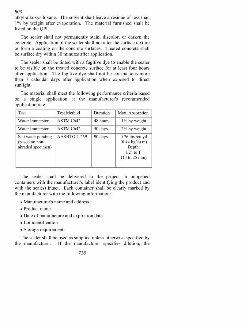
803 alkyl-alkoxysiloxane. The solvent shall leave a residue of less than 1% by weight after evaporation. The material furnished shall be listed on the QPL.
The sealer shall not permanently stain, discolor, or darken the concrete. Application of the sealer shall not alter the surface texture or form a coating on the concrete surfaces. Treated concrete shall be surface dry within 30 minutes after application.
The sealer shall be tinted with a fugitive dye to enable the sealer to be visible on the treated concrete surface for at least four hours after application. The fugitive dye shall not be conspicuous more than 7 calendar days after application when exposed to direct sunlight.
The material shall meet the following performance criteria based on a single application at the manufacturer's recommended application rate:
Test Test Method Duration Max. Absorption
Water Immersion ASTM C642 48 hours 1% by weight
Water Immersion ASTM C642 50 days 2% by weight
Salt water ponding (based on non-abraded specimen)
AASHTO T 259 90 days 0.76 lbs./cu yd (0.44 kg/cu m)
Depth: 1/2" to 1"
(13 to 25 mm)
The sealer shall be delivered to the project in unopened
containers with the manufacturer's label identifying the product and with the seal(s) intact. Each container shall be clearly marked by the manufacturer with the following information:
• Manufacturer's name and address. • Product name. • Date of manufacture and expiration date. • Lot identification. • Storage requirements.
The sealer shall be used as supplied unless otherwise specified by the manufacturer. If the manufacturer specifies dilution, the
718
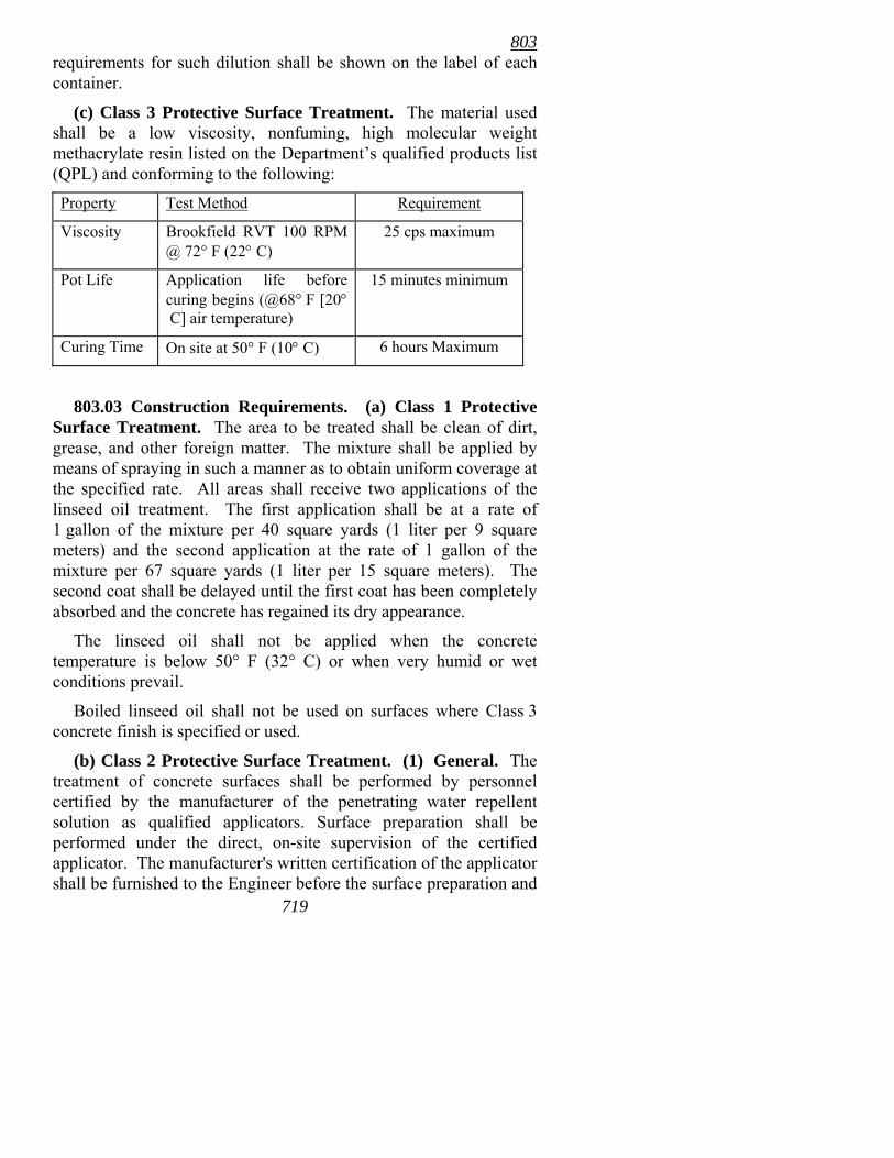
803 requirements for such dilution shall be shown on the label of each container.
(c) Class 3 Protective Surface Treatment. The material used shall be a low viscosity, nonfuming, high molecular weight methacrylate resin listed on the Department�s qualified products list (QPL) and conforming to the following:
Property Test Method Requirement
Viscosity Brookfield RVT 100 RPM @ 72° F (22° C)
25 cps maximum
Pot Life Application life before curing begins (@68° F [20° C] air temperature)
15 minutes minimum
Curing Time On site at 50° F (10° C) 6 hours Maximum
803.03 Construction Requirements. (a) Class 1 Protective Surface Treatment. The area to be treated shall be clean of dirt, grease, and other foreign matter. The mixture shall be applied by means of spraying in such a manner as to obtain uniform coverage at the specified rate. All areas shall receive two applications of the linseed oil treatment. The first application shall be at a rate of 1 gallon of the mixture per 40 square yards (1 liter per 9 square meters) and the second application at the rate of 1 gallon of the mixture per 67 square yards (1 liter per 15 square meters). The second coat shall be delayed until the first coat has been completely absorbed and the concrete has regained its dry appearance.
The linseed oil shall not be applied when the concrete temperature is below 50° F (32° C) or when very humid or wet conditions prevail.
Boiled linseed oil shall not be used on surfaces where Class 3 concrete finish is specified or used.
719
(b) Class 2 Protective Surface Treatment. (1) General. The treatment of concrete surfaces shall be performed by personnel certified by the manufacturer of the penetrating water repellent solution as qualified applicators. Surface preparation shall be performed under the direct, on-site supervision of the certified applicator. The manufacturer's written certification of the applicator shall be furnished to the Engineer before the surface preparation and
803 actual application is begun. The application, including surface preparation, shall comply with the manufacturer's explicit procedures. Before beginning the work, the Contractor shall submit to the Engineer documentation of the procedures to be used. The procedures shown in the documentation shall include, but are not limited to:
The identification of the product to be used by brand name and name of the manufacturer.
•
•
•
• • • • •
•
•
•
•
A copy of the manufacturer's unabridged application procedures. A description of the manufacturer's recommended surface preparation methods and the equipment to be used. Weather and surface moisture limitations. Time between surface preparation and application. Time traffic should be kept off the treated surface. Re-treatment procedures. A copy of the manufacturer's authorized applicator certificate for the personnel approved to perform the work.
(2) Surface Preparation. All concrete surfaces shall be thoroughly cleaned before application of the penetrating water repellent solution. The method of cleaning shall remove all traces of curing compound, laitance, dirt, dust, salt, oil, asphalt or other foreign materials, but shall not cause undue damage to the surface, remove or alter the existing surface finish or texture, or expose the coarse aggregate. Unless otherwise specified, the equipment used for preparation of the surface shall comply with one of the following:
Compressed air pressure type sand blasting equipment of proper size and capacity to clean concrete surfaces as specified. A portable machine designed especially for cleaning horizontal concrete surfaces using recyclable steel shot blasting techniques. A hot water pressure system for cleaning concrete surfaces using 160° F (71° C) minimum temperature water at a minimum 3500 psi (24 MPa) nozzle pressure. A high pressure cold water washer unit for cleaning concrete surfaces using a minimum of 7500 psi (52 MPa) nozzle pressure.
720
803 • Steam jet cleaning equipment for cleaning concrete
surfaces using 320° F (160° C) water temperature at 300 psi (2 MPa) operating pressure.
Concrete surfaces prepared for treatment shall be approved by the certified applicator.
(3) Application. The Contractor shall notify the Engineer at least one day before beginning application. The concrete shall have aged at least 28 calendar days and shall be surface dry for at least 24 hours before treatment begins. Concrete surfaces that become contaminated before the sealer is applied shall be re-cleaned. The Contractor shall use the equipment recommended by the manufacturer for application of the sealer. Unless otherwise specified, the sealer shall be applied with low pressure airless spray equipment operating at 15 psi to 40 psi (100 kPa to 275 kPa) pressure.
The sealer shall be applied in the manner and at the rate recommended by the manufacturer that will obtain a minimum penetration of 1/8" (3.0 mm). The rate of application shall be adjusted for vertical surfaces and surfaces that have been tined or roughened as specified by the manufacturer. The certified applicator shall determine if re-treatment is required due to weather conditions. If re-treatment is required, the re-treatment shall be performed as specified by the manufacturer and shall be at no additional cost to the Department.
No traffic of any kind will be permitted on bridge decks until the sealer has completely penetrated and is surface dry.
(4) Certification. After treatment has been completed, the Contractor shall submit a certification that the sealer was applied by personnel certified by the manufacturer and was done in compliance with these specifications.
(c) Class 3 Protective Surface Treatment. Surface preparation of the areas to be sealed with Class 3 Protective Surface Treatments shall be accomplished with one of the methods specified above for Class 2 Protective Surface Treatments, Subsection 803.02(b)(2), except that approval of the prepared surface by a certified applicator will not be required.
721
803 Application of the surface treatment shall not be performed when
the concrete surface temperature is less than 50° F (10° C) or more than 100° F (38° C).
For treatment of individual cracks, the treatment shall be applied at a rate to completely fill the crack and repeated as necessary to bring the filler flush with the surrounding surface. Cracks wider than 1/8" (3.0 mm) shall be prefilled with fine sand according to the manufacturers� recommendations.
Traffic shall not be permitted on the treated surface until the area is tack free.
803.04 Method of Measurement. (a) Class 1 Protective Surface Treatment. Class 1 Protective Surface Treatment applied at the direction of the Engineer will be measured by the gallon (liter) of boiled linseed oil used in the mixture prior to thinning. The material used for thinning the mixture will not be measured.
(b) Class 2 Protective Surface Treatment. Class 2 Protective Surface Treatment will be measured by the square yard (square meter). Measurement will be made of the actual area covered as directed.
(c) Class 3 Protective Surface Treatment. Class 3 Protective Surface Treatment will be measured by the linear foot (meter) of crack sealed.
The quantities shown on the plans for Class 1 or 2 Protective Surface Treatment system will be considered as the final quantities and no further measurement will be made unless, in the opinion of the Engineer or upon evidence furnished by the Contractor, substantial variations exist between quantities shown on the plans and actual quantities due to changes in alignment or dimensions or to apparent errors.
722
803.05 Basis of Payment. (a) Class 1 Protective Surface Treatment. Work completed and accepted and measured as provided above will be paid for at the contract unit price bid per gallon (liter) for Class 1 Protective Surface Treatment, which price shall be full compensation for cleaning, wetting, and other preparation of the surface to be treated; for furnishing the linseed oil and thinner; for mixing and application of the mixture; and for all labor, tools, equipment, and incidentals necessary to complete the work.
803 (b) Class 2 Protective Surface Treatment. Work completed and
accepted and measured as provided above will be paid for at the contract unit price bid per square yard (square meter) for Class 2 Protective Surface Treatment, which price shall be full compensation for furnishing all materials; for cleaning and preparing the surfaces to be treated; for application of the sealer; and for all labor, equipment, tools, and incidentals necessary to complete the work.
(c) Class 3 Protective Surface Treatment. Work completed and accepted and measured as provided above will be paid for at the contract unit price bid per linear foot (meter) for Class 3 Protective Surface Treatment, which price shall be full compensation for furnishing all materials; for cleaning and preparing the surfaces to be treated; for application of the sealer; and for all labor, equipment, tools, and incidentals necessary to complete the work.
Payment will be made under:
Pay Item Pay Unit
Class 1 Protective Surface Treatment Gallon (Liter)
Class 2 Protective Surface Treatment Square Yard (Square Meter)
Class 3 Protective Surface Treatment Linear Foot (Meter)
723
804
724
SECTION 804 REINFORCING STEEL FOR STRUCTURES
804.01 Description. This item shall consist of reinforcing steel and miscellaneous accessories of the quality, type, size, and quantity designated, which shall be furnished and placed in concrete structures according to these specifications and in conformity with the details shown on the plans, or as directed.
804.02 Materials. (a) Bar Reinforcement. Bar reinforcement for concrete in sizes up to and including #18 (No. 57) shall conform to the requirements of AASHTO M 31 or M 53.
(b) Wire and Wire Fabric. Wire, when used as reinforcement in concrete, shall conform to the requirements of AASHTO M 32 or M 225.
Wire fabric, when used as reinforcement in concrete, shall conform to the requirements of AASHTO M 55 or M 221. All wire fabric shall meet the weld shear requirements for AASHTO M 55. The type of wire fabric shall be approved by the Engineer.
(c) Bar Mat Reinforcement. Bar mat reinforcement for concrete shall conform to the requirements of AASHTO M 54.
(d) Epoxy Coating. When specified, reinforcing steel bars shall be coated according to AASHTO M 284 using a coating material that meets the requirements of Annex A1 of AASHTO M 284.
The Contractor shall supply to the Engineer a written certification that properly identifies the number of each batch of coating material used in the order; the material, quantity represented, date of manufacture, and name and address of the manufacturer; and a statement that the supplied coating material meets the requirements of Annex A1 of AASHTO M 284.
Patching material, compatible with coating material, inert in concrete, and meeting the requirements of Annex A1 of AASHTO M 284, shall be provided by the epoxy coating manufacturer.
804.03 Bar Lists and Bending Diagrams. All reinforcing steel shall be fabricated to conform to the details shown on the plans. Pins used for bending reinforcing steel shall be equal to or larger than that shown on the plans. Bar lists and bending diagrams for reinforcing steel and bar supports will not be reviewed or approved
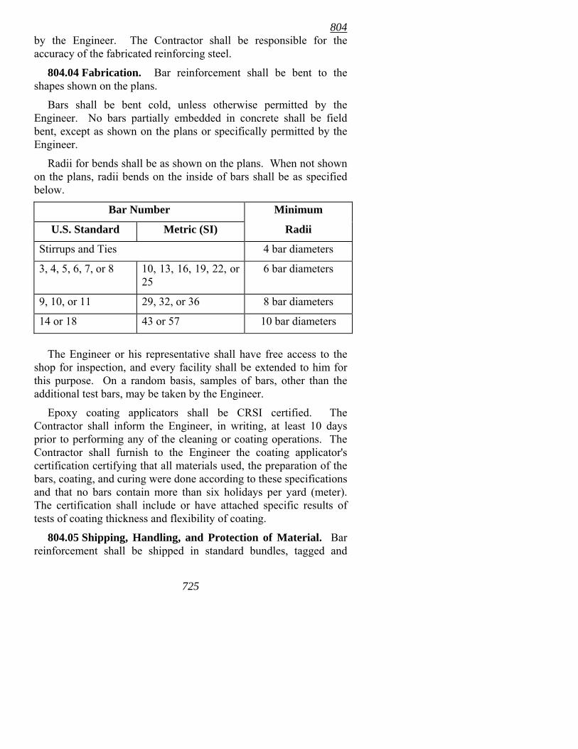
804
725
by the Engineer. The Contractor shall be responsible for the accuracy of the fabricated reinforcing steel.
804.04 Fabrication. Bar reinforcement shall be bent to the shapes shown on the plans.
Bars shall be bent cold, unless otherwise permitted by the Engineer. No bars partially embedded in concrete shall be field bent, except as shown on the plans or specifically permitted by the Engineer.
Radii for bends shall be as shown on the plans. When not shown on the plans, radii bends on the inside of bars shall be as specified below.
Bar Number Minimum
U.S. Standard Metric (SI) Radii
Stirrups and Ties 4 bar diameters
3, 4, 5, 6, 7, or 8 10, 13, 16, 19, 22, or 25
6 bar diameters
9, 10, or 11 29, 32, or 36 8 bar diameters
14 or 18 43 or 57 10 bar diameters
The Engineer or his representative shall have free access to the
shop for inspection, and every facility shall be extended to him for this purpose. On a random basis, samples of bars, other than the additional test bars, may be taken by the Engineer.
Epoxy coating applicators shall be CRSI certified. The Contractor shall inform the Engineer, in writing, at least 10 days prior to performing any of the cleaning or coating operations. The Contractor shall furnish to the Engineer the coating applicator's certification certifying that all materials used, the preparation of the bars, coating, and curing were done according to these specifications and that no bars contain more than six holidays per yard (meter). The certification shall include or have attached specific results of tests of coating thickness and flexibility of coating.
804.05 Shipping, Handling, and Protection of Material. Bar reinforcement shall be shipped in standard bundles, tagged and
804
72
marked according to the Code of Standard Practice of the Concrete Reinforcement Steel Institute.
Epoxy coated bars shall be prepared for shipment by use of excelsior or equivalent padded metal bands, or other methods that will prevent damage during shipment. Caution shall be used to avoid dragging or dropping the bundles. If bundled together for shipment, the bundles should be small, tightly banded with padded bands, and should be lifted with a strong back, multiple supports, or a platform bridge to prevent bar to bar abrasion from sags in the bar bundle. Epoxy coated bars shall be stored on padded and/or wooden supports. All systems for handling coated bars shall have padded contact areas. If, in the judgment of the Engineer, the coating is damaged to the extent that the coating no longer provides the intended protection, the material shall be returned to the coating applicator for repair or replacement. Patching materials or any required repair of the coating shall be at no cost to the Department.
Steel reinforcement shall be protected from damage. When placed in the work, it shall be free from dirt, detrimental rust or scale, paint, oil, or other foreign substance. Steel reinforcement shall be stored above the ground on skids, platforms, or other supports. Epoxy coated reinforcing steel that is not incorporated into the work within 90 calendar days after delivery to the project shall be protected from exposure to the sun.
Epoxy coating damaged during fabrication, shipping, or installation shall be repaired according to AASHTO M 284. Damaged areas less than 0.10 square inch (65 sq mm) need not be repaired but all areas larger than 0.10 square inch (65 sq mm) shall be repaired. The maximum amount of damage shall not exceed 2% of the surface area of each bar. All damaged areas shall be repaired with the material specified in Subsection 804.02(d) and according to the manufacturer's instructions. Repairs will be required on all sheared or cut ends of bars, end areas left bare during the coating process, and any areas where the entire coating is removed. All repairs shall be completed as soon as practicable and, in the case of bare end areas and sheared ends, before visible oxidation of the surface occurs. Epoxy coated bars shall not be flame cut.
The Contractor shall exercise caution when placing and vibrating concrete to prevent any damage to epoxy coated bars. In order to prevent the vibrator from damaging the coated bars, the head shall
6
804
727
be covered with a sheet of rubber or a similar material as approved by the Engineer.
804.06 Placing and Fastening. Steel reinforcement shall be accurately placed in the positions shown on the plans and firmly held during the placing and setting of concrete. Bars shall be tied at all intersections except where spacing is less than 12" (300 mm) in each direction, in which case alternate intersections shall be tied.
Bundled bars shall be tied together at not more than 6' (2 m) centers.
Bar positions or clearances from the forms shall be maintained by means of stays, ties, hangers, or other approved devices. Reinforcing steel shall not be welded unless detailed on the plans or authorized in writing by the Engineer. Any authorized welding shall comply with Subsection 807.26. Metal bar supports that are in contact with the exterior surface of the concrete shall have protection conforming with the CRSI Specifications, Class 1 for Plastic Protected Bar Supports or Class 2 for Stainless Steel Bar Supports, with the further provision that the plastic protection may be applied either by a dipping operation or by the addition of premolded plastic tips to the legs of the supports. Epoxy Coated Bar Supports that are coated according to the provisions of CRSI �Manual of Standard Practice� with a minimum coating thickness of 5 mils (127 µm) may be substituted for Plastic Protected Bar Supports or Stainless Steel Bar Supports. All high chairs and bar bolsters shall be metal.
Plastic bar supports shall not be used.
When concrete is to rest on an excavated surface, layers of bars shall be supported above the surface by metal chairs or by precast mortar or concrete blocks. The use of rocks, pieces of stone or brick, pipe, wooden blocks, or chunks of concrete will not be permitted as bar supports or spacers.
Reinforcement shall be placed by the Contractor and inspected and approved by the Engineer before the placing of concrete begins. Concrete placed in violation of this provision may be rejected and removal required. Unless otherwise shown on the plans, the spacing of supports shall conform to the recommendations of CRSI.
If fabric reinforcement is shipped in rolls, it shall be straightened into flat sheets before being placed.
804
728
Epoxy coated bars shall be placed on plastic coated or epoxy coated metal supports and shall be held in place by use of plastic coated tie wires or molded plastic clips especially fabricated for this purpose. Bar supports for epoxy coated bars shall be fully coated metal supports. Epoxy coated bar supports shall be coated according to the provisions of CRSI �Manual of Standard Practice� and shall have a minimum coating thickness of 5 mils (127 µm). In placing epoxy coated bars, care shall be maintained to prevent coated bars from being damaged.
After the coated bars are secured to bar supports, a final visual inspection shall be made and all uncoated or damaged areas coated or repaired as required by the Engineer.
Any bar supports that deform under foot traffic or other construction activities shall not be used.
Reinforcing steel that is to be doweled into existing concrete shall be installed into drilled holes and secured using an approved non-shrink grout or a polyester/epoxy resin system listed on the QPL. The diameter of the drilled holes and the installation procedures shall be as recommended by the grout/epoxy resin system manufacturer.
804.07 Splicing. Reinforcing steel shall be furnished in the full lengths specified on the plans. Bars spliced as a result of unforeseen construction conditions or sequences will require the written approval of the Engineer. Splices shall meet the requirements of the current edition of the AASHTO Standard Specifications for Highway Bridges.
Secondary reinforcing used for distribution of loads, such as longitudinal bars in box culverts, retaining walls, and slabs for steel girder spans, may be lapped 32 bar diameters minimum if bars are #6 (No. 19) or smaller. Primary reinforcing for columns and retaining walls which require splicing as a result of the lowering of footings shall be spliced at the upper end of the original bars. Required lengths of splices for primary reinforcing will be determined by the Bridge Engineer.
In lapped splices, the bars shall be placed in contact and fastened together in such a manner as to maintain the minimum distance to the surface of the concrete as shown on the plans. Welded or mechanical splices shall be made only if detailed on the plans or
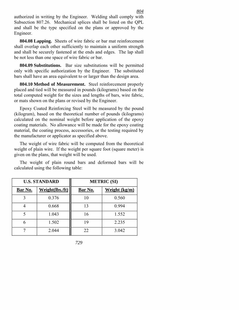
804
729
authorized in writing by the Engineer. Welding shall comply with Subsection 807.26. Mechanical splices shall be listed on the QPL and shall be the type specified on the plans or approved by the Engineer.
804.08 Lapping. Sheets of wire fabric or bar mat reinforcement shall overlap each other sufficiently to maintain a uniform strength and shall be securely fastened at the ends and edges. The lap shall be not less than one space of wire fabric or bar.
804.09 Substitutions. Bar size substitutions will be permitted only with specific authorization by the Engineer. The substituted bars shall have an area equivalent to or larger than the design area.
804.10 Method of Measurement. Steel reinforcement properly placed and tied will be measured in pounds (kilograms) based on the total computed weight for the sizes and lengths of bars, wire fabric, or mats shown on the plans or revised by the Engineer.
Epoxy Coated Reinforcing Steel will be measured by the pound (kilogram), based on the theoretical number of pounds (kilograms) calculated on the nominal weight before application of the epoxy coating materials. No allowance will be made for the epoxy coating material, the coating process, accessories, or the testing required by the manufacturer or applicator as specified above.
The weight of wire fabric will be computed from the theoretical weight of plain wire. If the weight per square foot (square meter) is given on the plans, that weight will be used.
The weight of plain round bars and deformed bars will be calculated using the following table:
U.S. STANDARD METRIC (SI)
Bar No. Weight(lbs./ft) Bar No. Weight (kg/m)
3 0.376 10 0.560
4 0.668 13 0.994
5 1.043 16 1.552
6 1.502 19 2.235
7 2.044 22 3.042
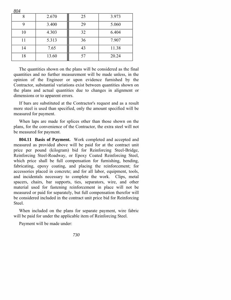
804 8 2.670 25 3.973
9 3.400 29 5.060
10 4.303 32 6.404
11 5.313 36 7.907
14 7.65 43 11.38
18 13.60 57 20.24
The quantities shown on the plans will be considered as the final
quantities and no further measurement will be made unless, in the opinion of the Engineer or upon evidence furnished by the Contractor, substantial variations exist between quantities shown on the plans and actual quantities due to changes in alignment or dimensions or to apparent errors.
If bars are substituted at the Contractor's request and as a result more steel is used than specified, only the amount specified will be measured for payment.
When laps are made for splices other than those shown on the plans, for the convenience of the Contractor, the extra steel will not be measured for payment.
804.11 Basis of Payment. Work completed and accepted and measured as provided above will be paid for at the contract unit price per pound (kilogram) bid for Reinforcing Steel-Bridge, Reinforcing Steel-Roadway, or Epoxy Coated Reinforcing Steel, which price shall be full compensation for furnishing, bending, fabricating, epoxy coating, and placing the reinforcement; for accessories placed in concrete; and for all labor, equipment, tools, and incidentals necessary to complete the work. Clips, metal spacers, chairs, bar supports, ties, separators, wire, and other material used for fastening reinforcement in place will not be measured or paid for separately, but full compensation therefor will be considered included in the contract unit price bid for Reinforcing Steel.
When included on the plans for separate payment, wire fabric will be paid for under the applicable item of Reinforcing Steel.
Payment will be made under:
730
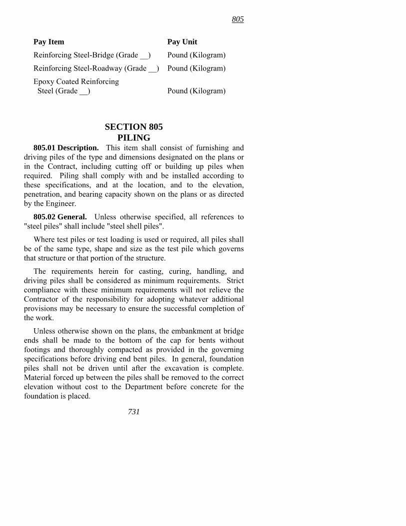
805
Pay Item Pay Unit
Reinforcing Steel-Bridge (Grade __) Pound (Kilogram)
Reinforcing Steel-Roadway (Grade __) Pound (Kilogram)
Epoxy Coated Reinforcing Steel (Grade __) Pound (Kilogram)
SECTION 805 PILING
805.01 Description. This item shall consist of furnishing and driving piles of the type and dimensions designated on the plans or in the Contract, including cutting off or building up piles when required. Piling shall comply with and be installed according to these specifications, and at the location, and to the elevation, penetration, and bearing capacity shown on the plans or as directed by the Engineer.
805.02 General. Unless otherwise specified, all references to "steel piles" shall include "steel shell piles".
Where test piles or test loading is used or required, all piles shall be of the same type, shape and size as the test pile which governs that structure or that portion of the structure.
The requirements herein for casting, curing, handling, and driving piles shall be considered as minimum requirements. Strict compliance with these minimum requirements will not relieve the Contractor of the responsibility for adopting whatever additional provisions may be necessary to ensure the successful completion of the work.
Unless otherwise shown on the plans, the embankment at bridge ends shall be made to the bottom of the cap for bents without footings and thoroughly compacted as provided in the governing specifications before driving end bent piles. In general, foundation piles shall not be driven until after the excavation is complete. Material forced up between the piles shall be removed to the correct elevation without cost to the Department before concrete for the foundation is placed.
731
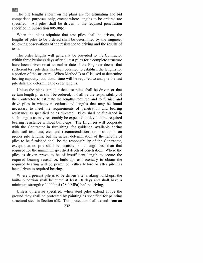
805 The pile lengths shown on the plans are for estimating and bid
comparison purposes only, except where lengths to be ordered are specified. All piles shall be driven to the required penetration specified in Subsection 805.08(e).
When the plans stipulate that test piles shall be driven, the lengths of piles to be ordered shall be determined by the Engineer following observations of the resistance to driving and the results of tests.
The order lengths will generally be provided to the Contractor within three business days after all test piles for a complete structure have been driven or at an earlier date if the Engineer deems that sufficient test pile data has been obtained to establish the lengths for a portion of the structure. When Method B or C is used to determine bearing capacity, additional time will be required to analyze the test pile data and determine the order lengths.
Unless the plans stipulate that test piles shall be driven or that certain length piles shall be ordered, it shall be the responsibility of the Contractor to estimate the lengths required and to furnish and drive piles in whatever sections and lengths that may be found necessary to meet the requirements of penetration and bearing resistance as specified or as directed. Piles shall be furnished in such lengths as may reasonably be expected to develop the required bearing resistance without build-ups. The Engineer will cooperate with the Contractor in furnishing, for guidance, available boring data, soil test data, etc., and recommendations or instructions on proper pile lengths, but the actual determination of the lengths of piles to be furnished shall be the responsibility of the Contractor, except that no pile shall be furnished of a length less than that required for the minimum specified depth of penetration. Where the piles as driven prove to be of insufficient length to secure the required bearing resistance, build-ups as necessary to obtain the required bearing will be permitted, either before or after pile has been driven to required bearing.
Where a precast pile is to be driven after making build-ups, the built-up portion shall be cured at least 10 days and shall have a minimum strength of 4000 psi (28.0 MPa) before driving.
732
Unless otherwise specified, when steel piles extend above the ground they shall be protected by painting as specified for painting structural steel in Section 638. This protection shall extend from an
805 elevation 18" (0.5 m) below the ground to the top of exposed pile, except no painting is required on the portion of pile encased in concrete.
The bearing capacity of piles will be determined by the Engineer as provided in the Contract by one or a combination of the following methods:
• Method A -- Empirical Pile Formulas. • Method B -- Wave Equation Analysis (WEAP). • Method C -- Dynamic Load Test. These methods are described in Subsection 805.09. Method A, Empirical Pile Formulas, will be used unless
otherwise specified. 805.03 Materials. (a) Class S(AE) Concrete, complying with
Section 802, shall be used for concrete piles, unless otherwise specified. The Contractor shall perform quality control and acceptance sampling and testing in accordance with Subsection 802.06 for piling build-ups.
(b) Reinforcing for piles shall comply with Section 804. (c) Unless otherwise specified, steel piles shall consist of
structural shapes of the section shown on the plans and shall comply with AASHTO M 270, Grade 36 (250).
(d) Unless otherwise specified, plain round steel shells shall comply with ASTM A 252, Grade 2. Shells shall be welded or seamless steel pipe. Concrete used to fill the driven steel shell shall be Class S complying with Section 802 unless otherwise noted.
Steel shells shall be uniform sections of the outside diameter and nominal thickness shown on the plans. The Contractor shall furnish shells of greater thickness, if necessary, to provide sufficient strength and rigidity and shall select equipment to permit driving without damage. Steel shells shall resist the earth pressure after being driven and retain their original form free from harmful distortions after they and adjacent shells in the bent or pier have been driven. Driving tips welded to the end of the steel shell shall be installed according to the plans. Such welding shall form a watertight joint.
Steel shell piles shall be marked by the manufacturer near both ends of the pile. Marking shall be in accordance with ASTM A 252.
733
805 (e) Driving points, when called for on the plans, shall be listed on
the QPL. (f) Welding of steel and steel shell piles, including attachment of
driving tips and points, shall be done by certified welders using the shielded metal arc method and shall comply with the governing specifications designated in Subsection 807.26. Other welding methods may be used with the written approval of the Engineer.
805.04 Manufacture of Precast Concrete Piles. (a) General. Precast concrete piles shall be constructed according to the details shown on the plans and the provisions of Section 802, insofar as they are applicable, supplemented by the requirements of this subsection.
Piles cast off the job site shall be subject to the same requirements as for piles cast at the job site and will be subject to further inspection after delivery. Piles manufactured off the job site must bear evidence that the component materials have been tested and approved and that the construction methods have been inspected by an inspector approved by the Engineer.
(b) Form Work. Forms for precast concrete piles shall comply with the general requirements for concrete form work as provided in Subsections 802.21 and 802.22. Forms shall be accessible for tamping and consolidation of the concrete. Side forms shall not be removed in less than 24 hours after placing the concrete. The entire pile shall remain supported for at least 7 calendar days and shall not be subjected to any handling stress until the concrete has cured for at least 21 calendar days. These periods may be shortened or lengthened when the Engineer has determined that the concrete has attained the minimum specified compressive strength. However, no forms shall be removed in less than 12 hours and no piles moved in less than 16 hours. For prestressed piles, form removal shall comply with Subsection 802.21(g).
(c) Reinforcement. For precast piles, reinforcement shall be placed according to the details shown on the plans.
(d) Casting. Concrete shall not be deposited in the forms until the Engineer has inspected the placing of reinforcement, anchorages, and prestressing steel and has given approval. The piles may be cast in either a horizontal or a vertical position. Special care shall be taken to place the concrete so as to avoid displacement of and to
734
805 produce a satisfactory bond with the reinforcement, and to avoid the formation of stone pockets, honeycomb, or other such defects.
The concrete in each pile shall be placed continuously and shall be consolidated by vibrating or by other means acceptable to the Engineer. The forms shall be over filled, the surplus concrete screeded off, and the top surfaces finished to a uniform texture similar to that produced by the forms.
(e) Finish. As soon as the forms are removed, concrete piles shall be carefully pointed with 1:2 mortar and given a Class 1 finish according to Subsection 802.19.
(f) Curing. Concrete piles shall be cured as provided in Subsections 802.21(g) and 802.22(f). The periods for curing and setting may be shortened or lengthened subject to such suitable tests as may be made to determine the quality and strength of the concrete. Piles may be driven when the concrete is found to have a compressive strength of not less than 4000 psi (28.0 MPa), provided further that in no case shall piles be driven in less than 10 calendar days.
805.05 Handling and Storage of Piles. (a) Precast Concrete Piles. Removal of forms, curing, storing, transporting, and handling precast concrete piles shall be accomplished in such manner as to avoid excessive bending stresses, cracking, spalling, or other injurious results. In raising a precast pile, it shall be suspended, as a minimum, at points as shown on the plans. For a three-point pickup, ropes or cables supported over pulleys shall be used to equalize the supporting forces.
Stored piles shall be placed on skids of timber or other suitable material. The skids, as a minimum, shall be placed at the pick-up points.
(b) Steel Piles. The method of storing and handling shall be such as to avoid injury to the piles. When steel piles are to be stored, they shall be placed on skids that will raise them above the ground. A sufficient number of skids shall be used to prevent excessive deflection.
805.06 Defective Piles. The Contractor shall not subject piles to excessive abuse that will produce cracking, crushing, spalling, or deformation of the pile. Manipulation of piles to force them into proper position, considered by the Engineer to be excessive, will not
735
805 be permitted. Any pile damaged by reason of internal defects or improper driving, or any pile driven out of its proper location or driven below the elevation fixed by the plans or the Engineer, shall be corrected at no cost to the Department by one of the following methods, as approved by the Engineer:
• The pile may be withdrawn and replaced by a new and, if necessary, longer pile.
• A second pile may be driven adjacent to the defective or low pile.
• The pile may be spliced or built up as otherwise provided herein, or a sufficient portion of the footing extended to properly embed the pile.
Piles pushed up by the driving of adjacent piles or by any other cause shall be re-driven to grade.
Any crushed or damaged portion of piling may be cut off and built up or the pile completely replaced, as approved by the Engineer. Cutoff, buildup, and/or replacement of damaged piles shall be at no cost to the Department.
805.07 Driving Equipment. Driving equipment that damages the piling shall not be used.
(a) Hammers. Unless otherwise specified on the plans, all piling shall be driven with an air, steam, or diesel hammer. Gravity hammers will be permitted only when shown on the plans or as elsewhere allowed by the specifications.
The plant and equipment furnished for air or steam hammers shall have sufficient capacity to maintain, under working conditions, the pressure at the hammer specified by the manufacturer. Accurate pressure gauges shall be placed at the boiler or tank and at the hammer so that the drop in pressure between the gauges can be determined.
When a single acting diesel hammer is used, it shall be equipped with a stroke indicator or the Contractor must furnish a method approved by the Engineer for determining the actual stroke. When a double acting diesel hammer is used, it shall be equipped with a bounce chamber pressure gauge in good working order mounted near ground level so as to be conveniently read by the Engineer when monitoring energy output of the hammer. The Contractor 736
805 shall provide charts that equate the chamber pressure to equivalent energy.
(1) Hammers for Steel Piles. When an air, steam, or diesel hammer is used, the total energy developed by the hammer shall be not less than 10,000 foot-pounds (13 500 joules) per blow.
Gravity hammers for driving steel piles, when allowed, shall weigh not less than 4000 pounds (1800 kg) and in no case shall the weight of the hammer be less than the combined weight of driving head and pile. The fall shall be so regulated as to avoid injury to the piles and shall in no case exceed 15' (4.5 m).
(2) Hammers for Precast Concrete and Steel Shell Piles. Unless otherwise provided, the hammer shall have a ram weight that is at least 1/5 the weight of the pile being driven, and shall develop an energy per blow at each stroke of the piston of not less than one foot-pound for each pound (3 j/kg) of weight to be driven. In no case shall the weight of the ram be less than 2700 pounds (1200 kg) nor the total energy developed by the hammer be less than 12,500 foot-pounds (16 900 joules) per blow.
(b) Driving Protection. (1) Hammer Cushion. All impact pile driving equipment except gravity hammers shall be equipped with a hammer cushion of suitable thickness to prevent damage to the hammer or pile and to ensure uniform driving behavior. Hammer cushions shall be made of durable, manufactured materials, complying with the hammer manufacturer's guidelines except that all wood, wire rope, and asbestos hammer cushions are specifically prohibited. A striker plate as recommended by the hammer manufacturer shall be placed on the hammer cushion to ensure uniform compression of the cushion material. The hammer cushion shall be inspected in the presence of the Engineer before beginning pile driving at each structure or after each 100 hours of pile driving, whichever is more frequent. When the thickness of a hammer cushion is reduced by more than 25% of its original thickness, it shall be replaced by the Contractor before driving is permitted to continue.
737
(2) Pile Drive Head. A pile driven with an impact hammer requires an adequate drive head to distribute the hammer blow to the pile head. The drive head shall be axially aligned with the hammer and the pile. The drive head shall be guided by the leads and shall not be free-swinging. The drive head shall fit around the pile head
805 in a manner that will prevent transfer of torsional forces during driving while maintaining proper alignment of hammer and pile.
For steel and timber piles, the pile heads shall be cut squarely and a drive head, as recommended by the hammer manufacturer, shall be provided to hold the axis of the pile in line with the axis of the hammer.
For precast concrete and prestressed concrete piles, the pile head shall be plane and perpendicular to the longitudinal axis of the pile to prevent eccentric impacts from the drive head.
For special types of piles, appropriate driving heads, mandrels, or other devices shall be provided according to the manufacturer's recommendations so that the piles may be driven without damage.
(3) Pile Cushion. The heads of concrete piles shall be protected by a pile cushion made of plywood. The plywood thickness placed on the pile head before driving shall not be less than 4" (100 mm). A new pile cushion shall be provided for each pile. In addition, the pile cushion shall be replaced if, during the driving of any pile, the cushion is either compressed more than one-half the original thickness or begins to burn. The pile cushion dimensions and area shall match the cross sectional area of the pile head.
(c) Driving Equipment Information. The Contractor shall submit to the Engineer, for information and record purposes, pile driving equipment information at least 30 days before driving piles. The information shall be submitted on a Pile and Driving Equipment Data Form, which will be supplied by the Engineer. Any change in the driving system will require the Contractor to submit a new Pile and Driving Equipment Data Form.
(d) Additional Equipment. In case the required penetration is not obtained with a hammer complying with the above minimum requirements, the Contractor shall provide a different hammer and/or sufficient additional equipment at no cost to the Department. Additional equipment not otherwise provided for herein shall be approved by the Engineer prior to its use.
(e) Leads. Pile driver leads shall be constructed in such a manner as to provide freedom for vertical movement of the hammer and shall be held in position in such a manner as to ensure adequate support to the pile during driving. The axis of the leads and hammer 738
805 shall coincide with the axis of the pile as nearly as practicable. Except where piles are driven through water, the leads shall be of sufficient length so that the use of a follower will not be necessary.
(f) Followers. Unless otherwise specified on the plans, the driving of piling with a follower will be allowed only with the written permission of the Engineer. All long piles designated on the plans as test piles shall be driven without a follower. The long pile(s) will be used to establish the required pile penetration for piles that are driven with a follower. All cut-offs or build-ups of long piles will be paid for as provided in Subsection 805.15.
(g) Water Jets. Unless otherwise shown on the plans, water jets may be used only with the written approval of the Engineer. When water jets are used, the number of jets and the volume and pressure of the water at the jet nozzles shall be of sufficient capacity to freely erode the material adjacent to the pile. Before the desired penetration is reached, the jets shall be withdrawn and the pile shall be driven with a hammer to secure its final penetration.
(h) Special Requirements for Method B (Wave Equation Analysis) or Method C (Dynamic Load Test). All pile driving equipment, including the pile driving hammer, hammer cushion, drive head, pile cushion, and other appurtenances to be furnished by the Contractor must be approved by the Engineer before any driving can take place. To obtain this approval, the Contractor shall submit a description of pile driving equipment to the Engineer, as required in Subsection 805.07(c).
Approval of pile driving equipment shall not relieve the Contractor of the responsibility to drive piles, free of damage, to the required bearing and penetration.
During pile driving operations, the Contractor shall use the approved driving system. Any change in the driving system will only be considered after the Contractor has submitted revised pile driving equipment data. The Contractor will be notified of the acceptance or rejection of the driving system changes within five business days of the Engineer's receipt of the requested change. The time required for submission, review, and approval of a revised driving system shall not constitute the basis for a contract time extension to the Contractor.
739
805 The following hammer efficiencies will be used in the Wave
Equation Analysis:
Hammer Type Efficiency in Percent
Single acting air/steam 67 Double acting air/steam 50 Diesel 72
The criteria that the Engineer will use to evaluate the acceptability of the driving equipment shall consist of: 1) the required number of hammer blows per 1 inch (25 mm); and 2) the pile stresses at both the required ultimate pile capacity and at a hammer blow count of 20 blows per 1 inch (25 mm). The required number of hammer blows indicated by wave equation analysis calculations and, as applicable, pile driving analyzer measurements at the required ultimate bearing capacity shall be between 3 and 12 per 1 inch (25 mm) for the driving equipment to be acceptable. In addition, the pile stresses to be generated by the driving equipment shall not exceed the values where pile damage impends. The point of impending damage is defined as follows:
• For steel piles, a compressive driving stress of 90% of the yield point, fy, of the pile material (0.90fy).
• For prestressed concrete piles, tensile stresses shall not exceed 912 psi (6.3 MPa) and compressive stresses shall not exceed 3550 psi (24.9 MPa).
• For non-prestressed concrete piles, tensile stresses shall not exceed 190 psi (1.3 MPa) and compressive stresses shall not exceed 3400 psi (23.8 MPa).
805.08 Driving. Unless otherwise specified, the use of pilot holes or other driving procedures not covered above will be permitted only when approved by the Engineer.
(a) Preboring. When specified, the Contractor shall prebore holes at pile locations and to depths shown on the plans or as directed by the Engineer. Prebored holes shall be smaller than the diameter or diagonal of the pile cross section and sufficient to allow penetration of the pile to the specified depth. If subsurface obstructions, such as boulders or rock layers, are encountered, the hole diameter may be increased to the least dimension that is adequate for pile installation. Any void space remaining around the
740
805 pile after completion of driving shall be filled with sand, sand grout mixture, or other approved material. Material resulting from drilled holes shall be disposed of under Section 210. The use of spuds (a short strong driven member that is removed to make a hole for inserting a pile) will not be permitted in lieu of boring, unless specifically authorized by the Engineer. When preboring is not specified, the Contractor may, with the approval of the Engineer, use preboring for his own convenience and at no cost to the Department.
(b) Protection of Concrete. No piles shall be driven within 20' (6 m) of a concrete placement, including placement in a steel shell, for a period of seven calendar days after placement.
(c) Splicing Piles. Concrete piles shall be furnished full length without splices.
Steel and steel shell piles shall be furnished full length with not more than one splice prior to driving. The full length is considered to be the length as may reasonable be expected to develop the required bearing resistance and the minimum specified depth of penetration. Two additional splices for build-up will be permitted in order to satisfy all conditions required to cease driving. A minimum length of 5′ (1.5 m) between splices shall be maintained. The sections shall be properly aligned to form a straight axis and shall be welded together in compliance with the plans and in a manner that will fully develop the section. Splices of steel shell piles shall form a watertight joint.
The splicing of steel piles and steel shell piles shall be accomplished by welding according to Subsection 805.03(f).
(d) Accuracy of Driving. Piles shall be driven with a variation of not more than 1/4" per foot (20 mm/m) from the vertical or from the batter shown on the plans, except that for pile bents the top of the completed pile shall be no more than 3" (75 mm) from the true position as shown on the plans. Foundation piles shall not be out of the position shown on the plans more than 4" (100 mm) after driving.
(e) Penetration. Piles shall be driven to the required depths of penetration shown on the plans and to greater depths if necessary to secure the bearing resistance specified.
If penetration requirements are not specified, piling shall have a minimum penetration of 20' (6 m) or be driven into the material shown on the plans or boring logs as rock. Penetration will be measured from the natural ground line for pile bents and from the bottom of footing or seal for foundation piles.
741
(f) Driving Inspection. Piling shall be driven under the observation of the Engineer or his representative so that data may be
805 obtained for determining the penetration and bearing value of the piles.
(g) Test Piles. When required, test piles shall be furnished and driven at locations as shown on the plans or as directed by the Engineer, and shall comply with the requirements herein provided. The driving equipment used for driving test piles shall be that which the Contractor proposes to use on the production piling.
Except as herein provided, all driving to meet the required penetration and bearing on a test pile shall be continuous. The only interruption permitted shall be that necessary for build-up of steel piling or excavating for concrete piling.
Unless otherwise specified or directed, test piles shall be made a part of the completed work and shall be cut off or built up to grade elevations as necessary. The Contractor will be given the option of driving test piles for his own information in estimating the length of piles even though they are not required or indicated on the plans; however, these piles will not be paid for as Test Piles.
If test piles were used to determine the order list according to Subsection 805.10 and the Engineer approves the use of another pile driver after the pile list has been established, the first pile driven with the new equipment shall be driven as a test pile. This pile shall be driven in a bent where a pile has been previously driven and will be used by the Engineer to establish new pile lengths. The length and location of the pile to be driven will be determined by the Engineer. If the Contract specifies that the bearing capacity will be determined by Method C, dynamic testing of the pile will be required. The cost of such dynamic testing shall be at no cost to the Department. The pile driven as a test pile shall be paid for at the contract unit price bid for Steel Piling, Steel Shell Piling, or Concrete Piling. The Contractor has the following two options after the new pile length has been established:
1. Order new piles of the proper length. The payment will be based on this new pile length and any cut-off or build-up will be measured and paid according to Subsections 805.14 and 805.15.
2. Use the existing piles from the original established pile length.
742
805 • If the new pile length is longer than the original length
any build-up will be paid only when it exceeds the new established pile length. Any cut-off will paid only when the final length in place is less than the original length.
• If the new pile length is shorter than the original length any build-up will be paid only when it exceeds the original length. Any cut-off will be paid only when the final length in place is shorter than the new established length.
805.09 Determination of Bearing Values. The bearing capacity of piles will be determined by the Engineer as provided in the Contract by one or a combination of the following methods. Method A, Empirical Pile Formulas, will be used unless otherwise specified. At any time, the Engineer may direct that driving be discontinued to prevent damage to a pile.
(a) Method A -- Empirical Pile Formulas. The safe bearing values for piles will be determined by the following formulas:
Hammer Type U.S. Standard Metric (SI) Gravity
2WH P = ------------------ S + 1.0
WH P = ------------------ 612(S + 25.4)
Single Acting Power
2WH P = ------------------ S + 0.1
WH P = ------------------ 612(S + 2.54)
Double Acting Power
2E P = ------------------ S + 0.1
E P = ------------------ 6(S + 2.54)
Where:
P = safe bearing value in pounds (kilonewtons),
W = weight, in pounds (kilograms), of striking parts of hammer,
H = height of fall (stroke) in feet (mm),
S = the average penetration in inches (mm) per blow for the last 5-10 blows for gravity hammers and the last 10-20 blows for power hammers, and
E = equivalent energy per blow in foot-pounds (joules).
743 The above formulas are applicable only when:
805 1) The hammer has a free fall. 2) The head of the pile is not broomed or crushed. 3) The penetration is reasonably quick and uniform. 4) There is no detectable bounce of the hammer after the blow. 5) A follower is not used. For a test pile, the penetration per blow shall be measured during
initial driving. For piling other than test piling, the penetration per blow shall be measured either during initial driving or during redriving. Redriving, when allowed, shall be with a warmed-up hammer operated at full energy after a pile set period, as determined by the Engineer. A warmed-up hammer is defined as a hammer that has applied at least 20 blows to another pile immediately before being used.
If bounce is detected, twice the height of the bounce of the hammer shall be deducted from "H" to determine its value in the formulas.
When a double acting steam or air hammer is used, the Contractor shall furnish tables from the manufacturer to equate the operating speed to equivalent energy. The equivalent energy used in calculating the safe bearing value shall not exceed 85% of the manufacturer's maximum energy rating.
When water jets are used in connection with the driving, the bearing value shall be determined by the above formulas from the results of driving after the jets have been withdrawn.
The character of the soil penetrated; conditions of driving; distributions, sizes, lengths, and weights of piles driven; and the computed load on the pile shall also be considered in determining the safe bearing value.
(1) Test Piles. The required safe bearing value shall be considered to have been obtained when the value remains at or above the specified value throughout the last 5 feet (1.5 m) of driving. Driving shall continue until the top of the pile is at plan grade unless practical refusal has been reached or damage to the pile is imminent. Practical refusal for test piles occurs when the calculated safe bearing value is three times the required safe bearing value. In no case shall the pile be driven less than that specified in Subsection 805.08(e).
744
805 (2) Piling. Piling shall be driven until the required safe
bearing is obtained. Driving shall continue until the top of the pile is at plan grade unless practical refusal has been reached or damage to the pile is imminent. The required safe bearing value shall be considered to have been obtained when the safe bearing value has been maintained for at least 5 feet (1.5 m). Practical refusal for production piling occurs when the calculated safe bearing value is two times the required safe bearing value. In no case shall the pile be driven less than that specified in Subsection 805.08(e).
If the required safe bearing value has not been obtained when the top of the pile is at plan grade, the pile shall be driven until one of the following conditions has been satisfied as approved by the Engineer:
• Soil may be excavated from around the pile, if necessary, and the pile driven until the required safe bearing has been obtained. Such excavation will not be paid for separately, but full compensation therefor will be considered included in the contract unit price bid for Steel Piling, Steel Shell Piling, or Concrete Piling.
• The pile shall be built-up and driven until the required safe bearing has been obtained. Measurement and payment for build-up will be made under Subsections 805.14 and 805.15.
(b) Method B -- Wave Equation Analysis (WEAP). The ultimate bearing capacity of a pile will be determined by using a Wave Equation Analysis. Soil, pile, and driving equipment properties to be used in this analysis will be determined by the Engineer using data obtained from the Contractor, test borings, and the plans.
Driving equipment shall comply with the requirements of Subsection 805.07.
Based on the Wave Equation Analysis, the Engineer will provide a bearing graph that shows a hammer blow count relationship for the required ultimate bearing capacity. Depending on the type hammer used, the bearing graph will be one of the following types: 1) stroke vs. blow count; 2) bounce chamber pressure vs. blow count; or 3) capacity vs. blow count.
745
805 The design bearing capacity of a pile shall be 0.364 of the
calculated ultimate bearing capacity as determined from a Wave Equation Analysis.
From the beginning of driving until the end of driving, the Engineer will measure the stroke and/or chamber pressure and count the number of hammer blows in 12" (300 mm) increments. Measurement of stroke and/or chamber pressure will not be required when a capacity vs. blow count type bearing graph is used.
(1) Test Piles. Test piles shall be driven using driving equipment established by the Wave Equation Analysis before other piles are ordered or driven.
Test piles shall be driven until: 1) the required ultimate bearing capacity or greater, as determined by the bearing graph, has been obtained for 3 feet (1.0 m); and 2) the top of the pile is at plan grade; but not to more than when 3) a hammer blow count of 20 blows per 1 inch (25 mm) has been obtained. In no case shall the pile be driven less than that specified in Subsection 805.08(e).
If the test pile has been driven to plan grade and has not satisfied conditions required to cease driving, the Engineer may direct the Contractor to excavate around a concrete pile to below plan grade to facilitate additional driving and testing in order to satisfy conditions required to cease driving. Steel piles shall be built-up and driving continued. The excavation or build-up and additional driving must be completed during the same day as the initial driving. The excavation will not be paid for separately, but full compensation therefor will be considered included in the contract unit price bid for Test Pile.
If the conditions to cease driving on a concrete test pile are not obtained with the excavation and additional driving, or if additional excavation is not allowed by the Engineer, the pile will be considered an unsuccessful test pile and the Engineer shall order a new test pile be driven. The length and location of the new test pile shall be determined by the Engineer.
The unsuccessful test pile shall be paid for at the contract unit price bid for Test Pile, and shall be built-up and driven to meet the requirements for piling as specified in Subsection 805.09(b)(2). Payment for the build-up will be made at the unit price bid for Concrete Piling.
746
805 The new test pile will be paid for at the contract unit price bid for
Test Pile. Payment for build-up of a successful test pile will be made at the contract unit price for Test Pile.
(2) Piling. Piling shall be driven continuously until: 1) the required ultimate bearing capacity or greater, as determined by bearing graph, has been obtained; and 2) the top of the pile is at plan grade; but not to more than when 3) a hammer blow count of 20 blows per 1 inch (25 mm) has been obtained. In no case shall the pile be driven less than that specified in Subsection 805.08(e).
If the required ultimate bearing capacity has not been obtained when the top of the pile is 6" (150 mm) above the plan grade, the pile shall be driven until one of the following conditions has been satisfied as approved by the Engineer:
• Soil may be excavated from around the pile, if necessary, and the pile driven until the required ultimate bearing capacity has been obtained. Such excavation will not be paid for separately, but full compensation therefor will be considered included in the contract unit price bid for Steel Piling, Steel Shell Piling, or Concrete Piling.
• The pile shall be built-up and driven until the required ultimate capacity has been obtained. Measurement and payment for build-up will be made under Subsections 805.14 and 805.15.
• After a 24 hour waiting period, the pile shall be struck with 20 blows from a warmed-up hammer and the penetration measured to determine if the required ultimate bearing capacity has been obtained. A warmed-up hammer is defined as a hammer that has applied at least 20 blows to another pile immediately before being used.
If this option is selected, initial driving shall cease when the top of the pile is 6" (150 mm) above the plan grade. An allowance of 3 linear feet (1 m) of piling will be made for each pile struck with the warmed-up hammer in addition to the actual length of accepted pile in place.
(c) Method C -- Dynamic Load Test. This subsection outlines the dynamic testing procedures to be used on the test piles indicated
747
805 on the plans to establish a bearing graph that shows a hammer blow count relationship for 90% and 100% of the required ultimate bearing capacity for piling. The design bearing capacity of a pile shall be 0.40 of the ultimate bearing capacity as determined by dynamic testing.
(1) General. The Contractor shall employ a specialty engineering firm experienced in the use of the wave equation analysis of piles computer program (WEAP), dynamic testing using the Case method, a pile driving analyzer (PDA), and the Case Pile Wave Analysis Program - Continuous Model (CAPWAPC) to perform the dynamic testing on the test pile. This firm shall furnish all equipment and make the analysis as outlined in this subsection.
A written report as specified in ASTM D 4945 shall be furnished to the Engineer showing the results and conclusions from the test. The report shall be submitted promptly to allow ample time for the Department to consider its contents and establish the bearing graph for the required ultimate bearing capacity. PDA field results for at least every other blow shall be included in the written report for the complete driving of the test pile.
(2) Driving Equipment. The driving equipment shall meet the requirements of Subsection 805.07. Driving equipment meeting the requirements of a successful dynamic load test on the test piles indicated on the plans will be considered acceptable for use on all test piling and piling for bridge site(s) or substructure units specified on the plans.
If dynamic testing indicates the driving equipment is not acceptable on the first test pile driven with the proposed driving equipment, the Contractor shall drive a new test pile in that bent with a different pile driver using dynamic testing as outlined herein. The length and location of the new test pile shall be determined by the Engineer. The new test pile driven with acceptable driving equipment will be paid for at the contract unit price bid for Test Pile and dynamic testing will be paid for at the contract unit price bid for Dynamic Pile Load Test.
748
The test pile driven with unacceptable driving equipment will be paid for at the contract unit price bid for Test Pile and the dynamic testing will be paid for at 50% of the contract unit price bid for Dynamic Pile Load Test. This test pile shall be built-up, if required, and driven to meet the requirements for piling as specified in
805 Subsection 805.09(c)(8). Payment for the build-up will be based on the unit price bid for Steel Piling, Steel Shell Piling, or Concrete Piling, as the case may be.
(3) Wave Equation Analysis. Before driving, a wave equation analysis is required on all test piles used to check the acceptability of the driving equipment.
The above data will be used to determine the adequacy of the hammer, the axial stresses in the pile, and the required number of blows per unit of penetration the hammer must deliver to obtain the required ultimate bearing capacity.
This will be determined by the specialty engineering firm and furnished to the Engineer in the form of bearing graphs. The Contractor will be notified of the acceptance or rejection of the graphs within seven business days of their receipt by the Engineer. No test piles shall be driven before the graphs are approved by the Engineer.
After evaluation by the wave equation, any changes in the driving equipment may require reevaluation, but in all cases such changes shall be approved by the Engineer before driving.
(4) Dynamic Pile Load Test. The Contractor shall drive test piles requiring dynamic testing at locations indicated on the plans using driving equipment established by the wave equation analysis, subject to change due to actual hammer performance and soil strength change. Dynamic testing shall be performed on the test pile during driving and shall comply with ASTM D 4945. Pile driving shall cease when dynamic testing indicates: 1) the required ultimate bearing capacity or greater has been maintained for 3 feet (1 m); and 2) when the top of the pile is at plan grade; but not to more than when 3) a hammer blow count of 20 blows per 1 inch (25 mm) has been obtained. In no case shall the pile be driven less than that specified in Subsection 805.08(e).
The Engineer will measure the stroke and/or chamber pressure and count the number of hammer blows in 12" (300 mm) increments from the beginning of driving until the required ultimate bearing capacity is first obtained and in 3" (75 mm) increments for the remainder of driving. Measurement of stroke and/or chamber pressure will not be required when a capacity vs. blow count type bearing graph is used. Approval of the driving equipment shall be
749
805 based on the average blow count per 1 inch (25 mm) measured for the first 3" (75 mm) increment where the required ultimate bearing capacity has been maintained by the PDA. Also, the CAPWAPC analysis must indicate a capacity at least 90% of the required ultimate bearing capacity.
If the test pile has been driven to plan grade and has not satisfied conditions required to cease driving, the Engineer may direct the Contractor to excavate around a concrete pile to below plan grade to facilitate additional driving and testing in order to satisfy conditions required to cease driving. Steel piles shall be built-up and driving continued. The excavation or build-up and additional driving must be completed during the same day as the initial driving. The excavation will not be paid for separately, but full compensation therefor will be considered included in the contract unit price bid for Test Pile. The additional driving and testing will not be considered a successive dynamic pile load test but a continuation of the initial drive.
If the conditions to cease driving on a concrete test pile are not obtained with the excavation and additional driving, or if additional excavation is not allowed by the Engineer, the pile will be considered an unsuccessful test pile and the Engineer shall order a new test pile be driven with dynamic testing. The length and location of the new test pile shall be determined by the Engineer.
The unsuccessful test pile shall be paid for at the contract unit price bid for Test Pile, and shall be built-up and driven to meet the requirements for piling as specified in Subsection 805.09(c)(8). Payment for the build-up will be made at the unit price bid for Concrete Piling. Dynamic testing for the unsuccessful test pile will be paid for at the contract unit price bid for Dynamic Pile Load Test.
The new test pile will be paid for at the contract unit price bid for Test Pile. Dynamic testing for the new test pile will be paid for at the contract unit price bid for Dynamic Pile Load Test. Payment for build-up of a successful test pile will be made at the contract unit price for Test Pile.
The Case method using a PDA shall be used to evaluate hammer and driving system performance, pile driving stresses, pile structural integrity, and pile bearing capacity.
750
805 If necessary, the Contractor shall reduce the driving energy
transmitted to the pile by using additional cushions or reducing the energy of the hammer in order to obtain acceptable stresses in the pile as specified in Subsection 805.07. If non-axial driving is indicated by dynamic test measurements, the Contractor shall immediately realign the driving system.
(5) CAPWAPC Analysis. The CAPWAPC analysis made after driving shall be used to predict the test pile's static bearing capacity and resistance distribution. This information shall be used to check Case method assumptions and to indicate the distribution of soil static resistance, quakes, and damping factors required for a wave equation analysis.
A CAPWAPC analysis will be required for each test pile requiring dynamic testing. The blow for a CAPWAPC analysis shall be selected from the last blows in the first 3" (75 mm) increment where the required ultimate bearing capacity was maintained by PDA. If the CAPWAPC analysis indicates an ultimate bearing capacity less than 90% of the required ultimate bearing capacity, a blow shall be selected from the last blows for each successive 3" (75 mm) increment for a CAPWAPC analysis until 90% of the required ultimate bearing capacity is obtained.
If the CAPWAPC analysis still indicates a bearing capacity less than 90% of the required ultimate bearing capacity at the point where driving was stopped, the test pile shall be driven until one of the following conditions has been satisfied: 1) the pile shall be driven a minimum of 2' (0.6 m) additional, or deeper, to obtain the required ultimate bearing capacity; or 2) after waiting up to 24 hours and after the first 20 blows of the hammer, the bearing capacity shall be determined based on 1 inch (25 mm) of penetration or 20 blows of the hammer, whichever occurs first. Dynamic testing and a CAPWAPC analysis will be required during the redriving and will be considered a successive dynamic pile load test. If necessary, the soil may be excavated from around the pile below plan grade, as approved by the Engineer, to facilitate driving and testing.
After a CAPWAPC analysis has been made at the end of driving a test pile, the Specialty Engineering firm shall establish a hammer blow count relationship for the required ultimate bearing capacity. A bearing graph shall be provided that shows the relationship for 90% and 100% for the required ultimate bearing capacity for piling.
751
805 Depending on the type of hammer used, the bearing graph shall be one of the following types: 1) stroke vs. blow count; 2) bounce chamber pressure vs. blow count; or 3) capacity vs. blow count. This information shall be developed using the refined wave equation (WEAP) with input data obtained from the CAPWAPC analysis.
(6) Successful Dynamic Load Test. A successful dynamic load test is one where: 1) the test pile has been driven with acceptable driving equipment to the proper length; and 2) at least 100% of the required ultimate bearing capacity as determined by dynamic testing and at least 90% of the required ultimate bearing capacity as verified by the CAPWAPC analysis has been obtained.
(7) Test Piling not Requiring Dynamic Testing. Test piles not requiring dynamic testing shall be driven until: 1) the required ultimate bearing capacity or greater, as established by the bearing graph, has been maintained for 3 feet (1.0 m); and 2) the top of the pile is at plan grade; but not to more than when 3) a hammer blow count of 20 blows per 1 inch (25 mm) has been obtained. In no case shall the pile be driven less than that specified in Subsection 805.08(e).
If the top of a test pile has been driven to plan grade and has not satisfied conditions required to cease driving, the Engineer may direct the Contractor to excavate around a concrete pile to below plan grade to facilitate additional driving and testing in order to satisfy conditions required to cease driving. Steel piles shall be built-up and driving continued. The excavation or build-up and additional driving must be completed during the same day as the initial driving. The excavation will not be paid for separately, but full compensation therefor will be considered included in the contract unit price bid for Test Pile.
If the conditions to cease driving on a concrete test pile are not obtained with the excavation and additional driving, or if additional excavation is not allowed by the Engineer, the pile will be considered an unsuccessful test pile and the Engineer shall order a new test pile be driven. The length and location of the new test pile shall be determined by the Engineer.
The unsuccessful test pile shall be paid for at the contract unit price bid for Test Pile, and shall be built-up and driven to meet the requirements for piling as specified in Subsection 805.09(c)(8).
752
805 Payment for the build-up will be made at the unit price bid for Concrete Piling.
The new test pile will be paid for at the contract unit price bid for Test Pile. Payment for build-up of a successful test pile will be made at the contract unit price for Test Pile.
The Engineer will observe all pile driving from beginning to end. Before the pile obtains the required ultimate bearing capacity, the Engineer will measure the stroke and/or chamber pressure and count the number of hammer blows in 12" (300 mm) increments. Measurement of stroke and/or chamber pressure will not be required when a capacity vs. blow count type bearing graph is used.
(8) Piling. Piling shall be driven continuously until: 1) at least 90% of the required ultimate bearing capacity, as determined by the bearing graph, has been obtained; and 2) the top of the pile is at plan grade but not to more than when 3) a hammer blow count of 20 blows per 1 inch (25 mm) has been obtained. In no case shall the pile be driven less than that specified in Subsection 805.08(e).
If 90% of the required ultimate bearing capacity has not been obtained when the top of the pile is 6" (150 mm) above the plan grade, the pile shall be driven until one of the following conditions has been satisfied as approved by the Engineer:
• Soil may be excavated from around the pile and the pile driven until at least 90% of the required ultimate bearing capacity has been obtained. The excavation will not be paid for separately, but full compensation therefor will be considered included in the contract unit price bid for Steel Piling, Steel Shell Piling, or Concrete Piling.
• After a 24 hour waiting period, the pile shall be struck with 20 blows from a warmed-up hammer. The results from the re-strike will be used to ascertain if at least 90% of the required ultimate bearing capacity, as determined by the bearing graph, has been obtained. A warmed-up hammer is defined as a hammer that has applied at least 20 blows to another pile immediately before being used.
If this option is selected, initial driving shall cease when the top of the pile is 6" (150 mm) above the plan grade. An allowance of 3 linear feet (1.0 m) of piling will be
753
805 made for each pile struck with the warmed up hammer in addition to the actual length of accepted pile in place.
• The pile shall be built-up and driven until at least 90% of the required ultimate capacity has been obtained.
The Engineer will observe all pile driving from beginning to end. Before the pile obtains the required ultimate bearing capacity, the Engineer will measure the stroke and/or chamber pressure and count the number of blows in 12" (300 mm) increments. Measurement of stroke and/or chamber pressure will not be required when a capacity vs. blow count type bearing graph is used.
805.10 Order Lists for Piling. The Contractor shall furnish piles according to an itemized list, which will be furnished by the Engineer, except as otherwise provided in Subsection 805.02, showing the number and length of piles. In determining lengths of piles for ordering and for quantities to be included in the Contract, the lengths given in the order list shall be based on the lengths that are assumed to remain in the completed structure. If the minimum bearing is not attained with the length of piling established by the Engineer, the Engineer will establish the length of pile build-up.
The Contractor may, at no cost to the Department, increase the lengths given to provide for fresh heading and for such additional length as may be necessary to suit the Contractor's method of operation.
805.11 Cut-off and Build-up of Piles. (a) Steel and Steel Shell Piles. After the pile has been driven to the minimum specified penetration and bearing resistance, it shall be driven, cut off, or built up, as necessary, to bring the finished top to plan grade. When the full approved pile length has been driven without attaining minimum bearing, the length of build-up shall be according to Subsection 805.10.
Cut-offs shall be made with a cutting torch or other acceptable method that will produce the desired smooth, level end of pile at the proper elevation. Build-ups shall be made by welding a splice on a section of pile in such manner as to fully develop the section of the pile according to the plans. Welding shall comply with Subsection 805.03(f).
Where the top of the pile is appreciably deformed or otherwise damaged below plan grade, the damaged portion shall be cut off and 754
805 replaced with a new section spliced in place. No additional compensation will be allowed for the material and work for this replacement.
(b) Concrete Piles. After the pile has been driven to the minimum specified penetration and bearing resistance, it shall be driven, cut off, or built up, as necessary, to bring the finished top to plan grade. When the full approved pile length has been driven without attaining minimum bearing, the pile shall be built up according to Subsection 805.10.
Cut-offs shall be accomplished by methods that will produce the desired end of pile at the proper elevation. The use of explosives to accomplish cut-off will not be allowed. Cut-off material shall not be used as piling but shall be disposed of according to Section 201.
When build-up is required, the concrete at the end of the pile shall be cut away leaving the reinforcing steel exposed for a length as shown on the plans. The final cut of the concrete shall be perpendicular to the axis of the pile. Reinforcement, as required by the plans, shall be securely fastened to the projecting steel and the necessary form work shall be placed, care being taken to prevent leakage along the pile. Prestressed piles may be built up using reinforcing shown for precast piles of the same size or an equivalent area of steel. The concrete used for the build-up shall comply with Section 802 for Class S(AE) concrete. Just before placing concrete, the top of the pile shall be thoroughly wetted and covered with a thin coating of neat cement, mortar, or other suitable bonding material. The forms shall remain in place a minimum of 24 hours, then carefully removed and the entire build-up finished and cured according to Subsection 805.04.
805.12 Pile Encasement When specified on the plans, a reinforced concrete encasement shall be placed around a driven steel pile. The encasement shall be constructed according to the details and at the locations shown on the plans. Lengths of pile encasement may be adjusted by the Engineer to fit the conditions at the time of construction.
The materials and construction requirements for this item shall comply with Section 802 and Section 804 for concrete and reinforcing steel respectively. The encased portion of a pile will not require painting.
755
805 805.13 Filling Steel Shell Piles. After driving and splicing is
completed, the steel shell shall be free of buckles, water, and other foreign matter, and shall be of required shape and dimensions before filling with concrete. The Contractor shall provide electric lights that may be lowered into the shell, mirrors, and other equipment and facilities necessary for the proper inspection of the shells. The tops of the shells shall be kept covered after inspection until placement of the concrete begins.
Concrete shall be placed in each shell in a single continuous operation with the flow of concrete directed down the center of the shell so as to consolidate the concrete by impact. The use of a tremie will not be required. Vibration or rodding of concrete will only be required to a depth of 5' (1.5 m) below the top of the shell. Placement of concrete shall continue after the shell is full until good quality concrete is evident at the top of the shell. The concrete shall be struck off flush with the top of the shell and finished to a smooth surface.
805.14 Method of Measurement. (a) General. Steel Piling, Steel Shell Piling, Concrete Piling, and Test Piles will be measured by the actual number of linear feet (meters) of accepted pile remaining in the finished structure after build-ups and/or cut-offs have been made, based upon lengths shown on the plans or established by the Engineer.
(b) Cut-off and Build-up. Allowance for pile cut-off, where piles have been furnished or built up according to the lengths shown on the plans or established by the Engineer, will be as follows:
Steel Piles 50% of cut-off length, plus 1 foot (0.3 m).
Concrete Piles 50% of cut-off length, plus 3 feet (1 m).
No allowance for cut-off will be made on piling for any length in excess of the lengths shown on the plans or established by the Engineer.
For piles furnished according to the lengths shown on the plans or established by the Engineer that are found to be too short and are spliced according to these specifications, an allowance of 3 linear feet (1 m) of piling will be made for each steel pile splice and 6 linear feet (2 m) for each concrete pile splice in addition to the actual length of accepted pile in place.
756
805 No allowance will be made for cut-off or build-up in any portion
of a pile that has been damaged, for splices made for the convenience of the Contractor, for extra length ordered for the Contractor's convenience, or for cutback necessary for splicing. Cut-off material shall be the property and responsibility of the Contractor.
(c) Steel Piles Over 18 m (60') in Length. When the order length for steel piling established according to Subsection 805.10 is greater than 60' (18 m), the Contractor may, at his option:
1) Furnish a pile that is spliced to obtain the specified order length. An allowance of 3 linear feet (1 m) will be made for this spliced pile in addition to the actual length of the pile furnished; or
2) Furnish an un-spliced pile of the specified order length.
For either of the above options, cut-off and/or additional build-up will be measured according to Subsection 805.14(b).
(d) Pile Encasement. Pile Encasement will be measured by the linear foot (meter). The measurement will be made parallel to the longitudinal centerline of the steel pile.
(e) Dynamic Pile Load Test. Dynamic Pile Load Test will be measured by the unit.
(f) Preboring. Preboring, when specified on the plans or in the Contract, will be measured by the linear foot (meter). Preboring performed for the Contractor's convenience will not be measured or paid for separately, but full compensation therefor will be considered included in the contract unit price bid for other items in the Contract.
805.15 Basis of Payment. (a) Piling. Work completed and accepted and measured as provided above will be paid for at the contract unit price bid per linear foot (meter) for Steel Piling, Steel Shell Piling, Concrete Piling, or Test Pile, as the case may be, of the size and type actually furnished. The price shall be full compensation for furnishing materials, including reinforcing steel in concrete piling; brackets, lugs, cap plates, pile tips, and driving points on steel piling; for transportation; for casting and handling; for driving, jetting, drilling, excavating, and painting; for furnishing
757
805 and placing concrete in steel shell piling; for cut-off, splicing, and build-up; and for all labor, equipment, tools, and incidentals necessary to complete the work. Unless otherwise specified, cut-off and build-up of successful test piles will be paid for at the contract unit price bid for Test Pile. Unless otherwise specified, cut-off and build-up of unsuccessful test piles will be paid for at the contract unit price bid for Steel Piling, Steel Shell Piling, or Concrete Piling, as applicable.
(b) Pile Encasement. Work completed and accepted and measured as provided above will be paid for at the contract unit price bid per linear foot (meter) for Pile Encasement, which price shall be full compensation for furnishing materials, forms, and bracing; for any required excavation; for placing all materials; and for all labor, equipment, tools, and incidentals necessary to complete the work.
(c) Dynamic Pile Load Test. Work completed and accepted and measured as provided above for the wave equation analysis, the dynamic pile load test, and the CAPWAPC analysis will be paid for at the contract unit price bid each for Dynamic Pile Load Test, which price shall be full compensation for furnishing materials and for all labor, equipment, tools, and incidentals necessary to complete the work. Each successive dynamic pile load test on the same pile will be paid for at 50% of the unit price bid for Dynamic Pile Load Test.
(d) Preboring. Work completed and accepted and measured as provided above will be paid for at the contract unit price bid per linear foot (meter) for Preboring, which price shall be full compensation for boring holes as required; for disposal of excess material; for furnishing and placing material in the void around the pile; and for all labor, equipment, tools, and incidentals necessary to complete the work.
Payment will be made under:
Pay Item Pay Unit
Steel Piling (___) Linear Foot (Meter) Steel Shell Piling (__" [___mm]dia.) Linear Foot (Meter) Concrete Piling (__" [__mm]__) Linear Foot (Meter) Test Pile (____)(____) Linear Foot (Meter) Pile Encasement Linear Foot (Meter)
758
805 Dynamic Pile Load Test Each Preboring Linear Foot (Meter)
SECTION 806
BRIDGE RAILINGS 806.01 Description. This item shall consist of railings for
bridges, headwalls, wingwalls, retaining walls, etc., of the material or combination of materials specified, constructed according to the plans and specifications.
806.02 Materials. (a) Aluminum Products. Aluminum railing, including tubing, pipe, extrusions, posts, and fastenings, shall be aluminum alloy meeting the requirements shown on the plans.
Aluminum alloy surfaces contacting concrete shall be coated with an aluminum impregnated caulking compound or other suitable material approved in writing by the Engineer.
The outside surfaces of flanges and edges of flanges of cast aluminum posts shall be given a #220 grit finish, after which all exposed surfaces of the cast posts shall be given a coat of clear lacquer suitable for use on aluminum materials. The inside surfaces of posts shall have no special finish.
Welding, where shown on the plans, shall be accomplished by an arc welding process in which no welding flux is used. AWS D 1.2, Welding of Aluminum Alloys, shall be the governing specification for aluminum products.
(b) Aluminum Coated Steel Products. Hot dip aluminum coating applied to steel products, including fasteners and accessories which will be in contact with aluminum surfaces, shall comply with the following specifications:
The material used for coating shall be 99% pure aluminum conforming to the specifications for Aluminum Association Alloy No. 1100.
The thickness of the coating shall be not less than 0.002" (0.05 mm) on any one individual specimen and the average of the specimens tested shall be not less than 0.0023" (0.058 mm). The thickness of coating may be determined by the use of a magnetic thickness gauge.
759
806 Surfaces to be coated shall be subjected to such cleaning,
pickling, fluxing, or abrasive blasting as are necessary to properly prepare such surfaces for the hot dip aluminum coat to follow. After being cleaned by abrasive blasting or other satisfactory methods, welds and welded areas shall be free from weld slag or other contamination.
After having been properly cleaned, the parts shall be dipped in the molten aluminum bath for such period as is necessary to obtain the proper coating. Upon removal from the bath, the items shall be processed to remove excess coating, followed by a water rinse and other supplementary treatments as required.
After coating, parts shall be tested to determine that the specified strength and ductility of the base metal have been retained. Parts that fail to meet the specified requirements may be tempered to restore any losses. After retesting, the parts shall conform to the specified requirements.
The aluminum coating on threads, except on tapped threads, shall not be subjected to a cutting, rolling, or finishing tool operation, unless specifically authorized by the Engineer. Nuts shall be tapped oversize sufficiently to permit hand turning.
The coating shall be continuous and uniform in thickness. The coating shall adhere tenaciously to the surface of the base metal.
Bolts shall be shipped with nuts assembled. The manufacturer shall employ such methods of packing coated products as may reasonably be required to ensure their receipt by the purchaser in a satisfactory condition.
(c) Steel Products. Steel railing, including tubing, pipe, extrusions, posts, and fastenings, shall meet the material specifications on the plans. Steel rail members shall be galvanized according to AASHTO M 111 after fabrication. Steel fasteners other than stainless steel shall be galvanized according to AASHTO M 232 or M 298, Class 40 or 50.
806.03 Line and Grade. The line and grade of the railing shall be true to that shown on the plans. Vertical members, including posts, shall be plumb unless otherwise noted on the plans.
806.04 Expansion Joints. Expansion joints shall be so constructed as to permit freedom of movement. After work has been
760
806 completed, loose or thin shells of mortar likely to spall under movement shall be carefully removed from expansion joints by means of a sharp chisel.
806.05 Construction Requirements. (a) General. Railings shall not be placed until the falsework for the span has been removed and the span is in its final position.
(b) Metal Rail Members. Fabrication and erection of metal rail members shall be accomplished according to the requirements of Section 807. In the case of welded railing, exposed joints shall be finished after welding by grinding or filing to give a neat appearance.
Aluminum rail members shall not be painted.
Metal rail members shall be carefully adjusted prior to fixing in place to ensure proper matching at abutting joints and correct alignment and camber throughout the length of the railing.
806.06 Method of Measurement. Bridge railings will be measured by the linear foot (meter). The measurement will be made along the roadway face of the railing, from end to end of each continuous length of railing.
The quantities shown on the plans will be considered as the final quantities and no further measurement will be made unless, in the opinion of the Engineer or upon evidence furnished by the Contractor, substantial variations exist between quantities shown on the plans and actual quantities due to changes in alignment or dimensions or to apparent errors.
806.07 Basis of Payment. Work completed and accepted and measured as provided above will be paid for at the contract unit price bid per linear foot (meter) for Metal Bridge Railing of the type specified, which price shall be full compensation for furnishing material, including posts, fittings, and fastenings for railing; for fabrication and erection; and for all labor, equipment, tools, and incidentals necessary to complete the work.
Payment will be made under:
Pay Item Pay Unit
Metal Bridge Railing (Type___) Linear Foot (Meter)
761
807
SECTION 807 STEEL STRUCTURES
807.01 Description. This item shall consist of furnishing, fabricating, assembling, erecting, and painting structural metals for bridge structures and other steel products according to these specifications and the plans.
GENERAL
807.02 Sufficiency of Fabricator. All structural steel fabricators shall be certified for AISC Category Sbr (Simple Steel Bridge Structures) or Cbr (Complex Steel Bridges) as appropriate, except as provided herein. In addition, the fabricator shall have the appropriate Paint Endorsement (P1, P2, or P3) which qualifies them for the application of sophisticated coating systems.
When the Contractor elects to purchase items of structural steel manufactured outside the United States, such materials shall be furnished only from those foreign manufacturers who have previously established, to the satisfaction of the Engineer, the sufficiency of their in-plant quality control to give satisfactory assurance of their ability to furnish material uniformly and consistently in conformance with the Specifications and according to Subsection 106.01.
Proof of sufficiency must be provided to the Engineer by the Contractor and the Engineer's approval obtained before foreign manufactured structural steel items are incorporated into the work. Proof may be established by: 1) the Contractor providing the Engineer with a detailed written certification by an established and approved independent testing and inspection laboratory or agency showing evidence that the foreign manufacturer has previously established in-plant quality control to give assurance of their ability to furnish material uniformly and consistently in conformance with the specifications, or 2) a thorough in-plant inspection of the foreign manufacturer's facilities by the Engineer or his appointed representative as deemed necessary by the Engineer.
The cost of determining sufficiency, established either by detailed written evidence or a thorough in-plant inspection by the Engineer or his appointed representative, shall be borne by the
762
807 Contractor. Payment of all expenses incurred by the Engineer or his appointed representative in making such in-plant inspection as deemed necessary by the Engineer shall be made by the Contractor to the Department upon receipt of detailed billing prepared by the Department and presented to the Contractor.
Prior to shipment or fabrication of any foreign produced structural steel, the Contractor shall obtain all the Certified Mill Test Reports, clearly identifiable to the lot of material to be shipped by heat numbers and color-coding, and submit these to the Engineer for complete review and analysis, and shall have received approval of them.
Structural steel materials that are manufactured outside the United States shall be delivered to the fabrication site where it shall be retained a sufficient period of time to permit inspection, sampling, and testing as deemed necessary by the Engineer prior to fabrication. The Contractor shall make all pieces of all materials available to the Engineer for inspection, sampling, and testing.
807.03 Governing Specifications. In case of conflict between the Standard Specifications and any referenced specifications in this Section, the Standard Specifications shall govern.
807.04 Shop Drawings Required of the Contractor. (a) Submission for Approval. Prints of the shop drawings for all steel product fabrication work shall be submitted to the Engineer for approval before work is begun in the shop. Material ordered or work accomplished prior to the approval of these drawings shall be at the Contractor's risk. Shop drawings for steel products and structures shall give full detailed dimensions and sizes of component parts of the product or structure, and details of miscellaneous parts, such as pins, nuts, bolts, rivets, drains, etc.
Shop drawings shall identify each piece of steel with an erection or assembly mark. Pieces made of different grades of steel shall not be given the same assembling or erecting mark, even though they are of identical dimensions and detail.
(b) Approved Drawings. Prints of the approved shop drawings for all work shall be furnished to the Engineer. The approval of shop drawings will cover only the general design features, and in no case shall this approval be considered to cover errors or omissions in shop details. The Contractor shall be responsible for the accuracy of
763
807 the shop drawings, the fabrication of material, and the fit of all connections and shall bear the cost of all extra work in erection caused by errors in shop drawings and for any changes in fabrication necessary for satisfactory erection. After shop drawings have been approved, no changes in dimensions or substitutions of sections shall be made without written approval.
MATERIALS
807.05 Structural Steel. Unless otherwise specified, structural steel shall conform to the requirements of Structural Steel for Bridges, AASHTO M 270, except that the Charpy V-Notch Impact test requirements shall apply only to materials designated on the contract drawings as main load carrying member components. When Charpy V-Notch tests are required, the test results shall conform to the requirements specified for Zone I minimum service temperature.
Grade 36 (250) shall be furnished unless otherwise specified.
Steel shall be furnished according to the following specifications:
(a) Carbon Steel. Unless otherwise specified, structural carbon steel for bolted or welded construction shall conform to AASHTO M 270, Grade 36 (250). Fill or shim plates ¼″ (6 mm) or less in thickness used in high strength bolted connections may be ASTM A 1011, SS, Grade 36 (250), Type 2, or Grade 40 (275).
(b) High-Strength Low-Alloy Structural Steel. High strength low alloy structural steel shall conform to AASHTO M 270, Grades 50 (345) or 50W (345W). Fill or shim plates ¼″ (6 mm) or less in thickness used in high strength bolted connections of painted bridges may be ASTM A 1011, SS, Grade 50 (340), or Grade 55 (380), HSLAS, Grade 50 (340), Class 1 or Grade 55 (380), Class 1.
Fill or shim plates ¼″ (6 mm) or less in thickness used in high strength bolted connections of unpainted weathering steel may be ASTM A 606, Type 4.
(c) High-Yield-Strength, Quenched and Tempered Alloy Steel Plate. High yield strength, quenched and tempered alloy steel plate shall conform to AASHTO M 270, Grade 100 (690).
Quenched and tempered alloy steel structural shapes and seamless mechanical tubing shall meet all of the mechanical and chemical requirements of AASHTO M 270, Grade 100 (690), except 764
807 that the specified maximum tensile strength may be 140,000 psi (965 MPa) for structural shapes and 145,000 psi (1000 MPa) for seamless mechanical tubing.
(d) Structural Steel for Eyebars. Steel for eyebars shall be of a weldable quality conforming to AASHTO M 270, Grade 36 (250), Grade 50 (345), or Grade 50W (345W).
807.06 High Strength Bolts, Nuts, and Washers for Structural Steel Connections. (a) Specifications. High strength bolts shall be heavy hex and shall conform to the requirements of AASHTO M 164 except as modified herein. Type 1 bolts shall be provided when used with painted structural steel or when galvanized bolts are specified. Type 3 bolts shall be provided when used with unpainted weathering structural steel. The maximum hardness of high strength bolts shall be 33 Hardness Rockwell C .
Nuts shall be heavy hex and shall conform to the requirements of AASHTO M 291 or AASHTO M 292. Nuts for plain, uncoated Type 1 bolts shall be Grade 2H, Grade DH or DH3 (Grade 10S, or 10S3). Nuts for Type 3 bolts shall be Grade DH3 (Grade 10S3). Nuts for galvanized bolts shall be Grade 2H or Grade DH (Grade 10S). When galvanized nuts are furnished, the zinc coating, overtapping, lubrication, and proof loading shall be in accordance with AASHTO M 291.
Washers shall conform to the requirements of AASHTO M 293. Where necessary, washers may be clipped on one side to a point not closer than 7/8 of the bolt diameter from the center of the washer. Beveled washers shall be used in the flanges of American Standard beams and channels. Weathering steel washers shall be used with Type 3 bolts.
When galvanized bolt assemblies are specified, the bolts, nuts, and washers shall be galvanized according to AASHTO M232, Class C, or AASHTO M 298, Class 50. All components in a fastener assembly shall be galvanized by the same process.
Galvanized nuts shall be provided with a lubricant that is clean and dry to the touch. The lubricant shall contain a visible dye so that a visual check can be made for the lubricant at the time of field installation. Plain, uncoated bolts, nuts, and washers must be "oily" to the touch when installed.
765
807 (b) Required Tests. High strength fasteners, plain and
galvanized, shall be subjected to a rotational capacity test according to AASHTO M 164, Section 6.2, and shall meet the following requirements:
1. Go through two times the required number of turns (from snug tight conditions) indicated in Table 807-1, in a Skidmore-Wilhelm Calibrator or equivalent tension measuring device, without stripping or failure.
2. During this test, the maximum recorded tension shall be equal to or greater than 1.15 times the Minimum Bolt Tension as shown in Table 807-3.
3. The measured torque needed to produce the Minimum Bolt Tension shall not exceed the value obtained by the following equation:
Torque = 0.25 x P x D
where:
Torque = Maximum Measured Torque (Foot-pounds [newton meter])
P = Measured Bolt Tension (pounds [kilonewtons]) D = Nominal Diameter (Feet [mm])
Proof load tests according to ASTM F 606M (F 606) Method 1 are required for the bolts. Wedge tests of full size bolts are required according to Section 8.3 of AASHTO M 164. Galvanized bolts shall be wedge tested after galvanizing. Proof load tests according to AASHTO M 291 are required for the nuts. The proof load tests for nuts to be used with galvanized bolts shall be performed after galvanizing, overtapping, and lubricating.
The Engineer shall be furnished with a manufacturer's certification for all high strength bolts, nuts, and washers used on the project. This certification shall provide a lot number, shop order number, or other identification such that the heat number from which the items were made can be traced. This identifying number shall also appear on the sealed shipping containers. The certification shall indicate when and where all testing was done, including the rotational capacity tests, and shall include the zinc thickness when galvanized bolts, nuts, and washers are used.
766
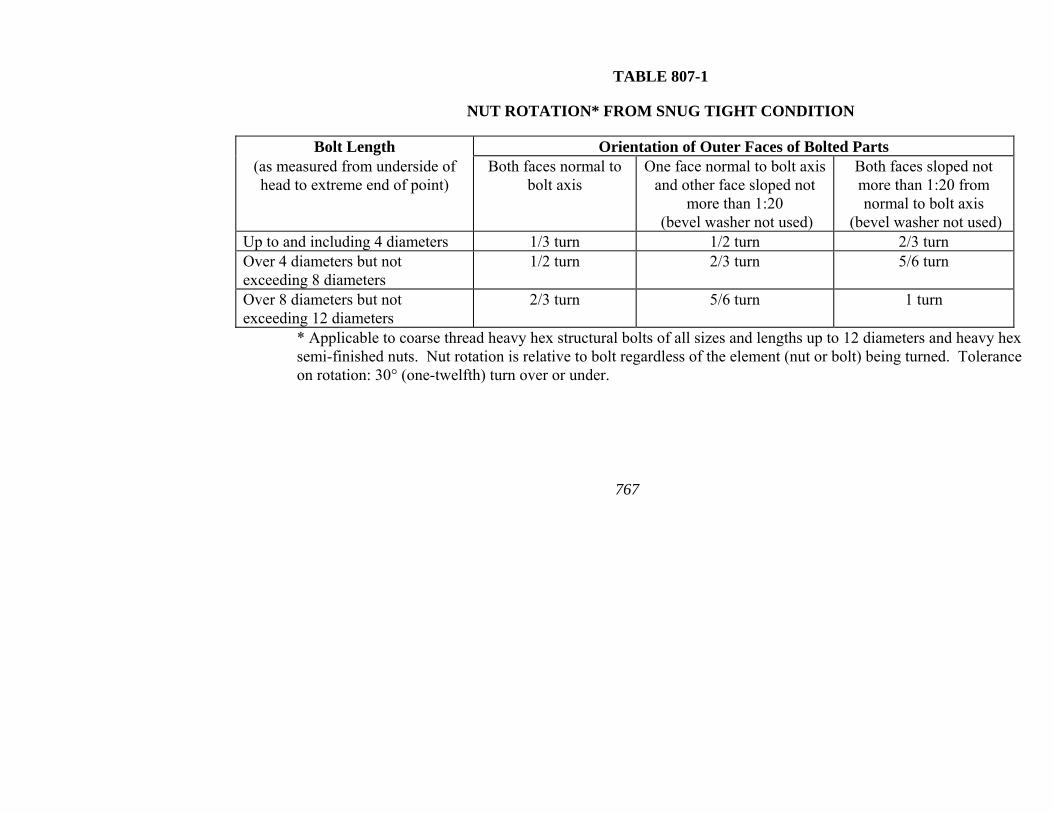
767
TABLE 807-1
NUT ROTATION* FROM SNUG TIGHT CONDITION
Bolt Length Orientation of Outer Faces of Bolted Parts (as measured from underside of head to extreme end of point)
Both faces normal to bolt axis
One face normal to bolt axis and other face sloped not
more than 1:20 (bevel washer not used)
Both faces sloped not more than 1:20 from normal to bolt axis
(bevel washer not used) Up to and including 4 diameters 1/3 turn 1/2 turn 2/3 turn Over 4 diameters but not exceeding 8 diameters
1/2 turn 2/3 turn 5/6 turn
Over 8 diameters but not exceeding 12 diameters
2/3 turn 5/6 turn 1 turn
* Applicable to coarse thread heavy hex structural bolts of all sizes and lengths up to 12 diameters and heavy hex semi-finished nuts. Nut rotation is relative to bolt regardless of the element (nut or bolt) being turned. Tolerance on rotation: 30° (one-twelfth) turn over or under.
807
768
807.07 Bridge Anchor Bolts. Unless otherwise specified, anchor bolts for bridges shall conform to AASHTO M 314, Grade 36 including supplementary requirement S1. Heavy Hex nuts shall conform to AASHTO M 291, Grade C or better, or to AASHTO M 292, Grade 2H. Washers shall conform to AASHTO M 293. All anchor bolts, nuts, and washers shall be galvanized according to AASHTO M 232, Class C, or AASHTO M 298, Class 50. Anchor bolts and nuts shall be galvanized by the same process. Nuts shall be provided with a lubricant that is clean and dry to the touch. The lubricant shall contain a visible dye so that a visual check can be made for the lubricant at the time of field installation.
807.08 Welded Stud Shear Connectors. Shear connector studs shall conform to the requirements of Steel Bars, Carbon, Cold Finished Standard Quality, AASHTO M 169, cold-drawn bars, Grades 1015, 1018, and 1020, either semi-killed or killed. If flux retaining caps are used, the steel for the caps shall be of a low carbon grade suitable for welding and shall comply with Steel, Carbon, Cold-rolled Strip, ASTM A 109M (A 109).
Tensile properties, as determined by tests of bar stock after drawing or of finished studs, shall conform to the following minimum requirements:
Tensile Strength 60,000 psi (415 MPa)
Elongation 20% in 2" (50 mm)
Reduction of area 50%
Tensile properties shall be determined according to the applicable sections of AASHTO T 244. Tensile tests of finished studs shall be made on studs welded to test plates using a test fixture conforming to ANSI/AASHTO/AWS D1.5 Bridge Welding Code requirements. If fracture occurs outside the middle half of the gage length, the test shall be repeated.
Finished studs shall be of uniform quality and condition, free from laps, fins, seams, cracks, twists, bends, or other injurious defects. Finish shall be as produced by cold drawing, cold rolling, or machining. Studs shall be marked to identify the manufacturer.
The manufacturer shall certify that the studs as delivered are in accordance with the material requirements of this Section. Certified
807
769
copies of in-plant quality control test reports shall be furnished to the Engineer.
Samples of studs of each type and size used may be selected, as necessary, for checking the requirements of this Section.
807.09 Steel Forgings and Steel Shafting. (a) Carbon Steel Forgings. Steel forgings shall conform to AASHTO M 102. Class C forgings shall be furnished unless otherwise specified.
(b) Cold Finished Carbon Steel Shafting. Cold finished carbon steel shafting shall conform to AASHTO M 169. Grades 10160 through 10300 shall be furnished unless otherwise specified.
(c) Alloy Steel Forgings. Alloy steel forgings shall conform to AASHTO M 102. Class G forging shall be furnished unless otherwise specified.
807.10 Steel Castings. (a) General. Steel castings for use in highway bridge components shall conform to AASHTO M 103. Grade 70-36 (485-250) steel shall be used unless otherwise specified.
(b) Chromium Alloy Castings. Chromium alloy steel castings shall conform to AASHTO M 163. Grade CA 15 shall be furnished unless otherwise specified.
807.11 Iron Castings. (a) General. Iron castings shall be gray iron castings conforming to AASHTO M 105, Class No. 30 unless otherwise specified.
(b) Workmanship and Finish. Iron castings shall be true to pattern in form and dimensions, free from pouring faults, sponginess, cracks, blow holes, and other defects.
Castings shall be boldly filleted at angles and the arrises shall be sharp.
(c) Cleaning. All castings shall be sandblasted or otherwise effectively cleaned of scale and sand and have a smooth, clean, and uniform surface.
807.12 Ductile Iron Castings. (a) General. Ductile iron castings shall conform to ASTM A 536, Grade 414-276-18, unless otherwise specified. In addition to the specified test coupons, test specimens from parts integral with the castings, such as risers, shall be tested for castings weighing more than 1000 pounds (454 kg) to
807
770
determine that the required quality is obtained throughout the casting.
(b) Workmanship and Finish. Iron castings shall be true to pattern in form and dimensions, free from pouring faults, sponginess, cracks, blow holes, and other defects.
Castings shall be boldly filleted at angles and the arrises shall be sharp.
(c) Cleaning. All castings shall be sandblasted or otherwise effectively cleaned of scale and sand and have a smooth, clean, and uniform surface.
807.13 Malleable Castings. (a) General. Malleable castings shall conform to ASTM A 47 (A 47M). Grade No. 35018 shall be furnished unless otherwise specified.
(b) Workmanship and Finish. Malleable castings shall be true to pattern in form and dimensions, free from pouring faults, sponginess, cracks, blow holes, and other defects.
Castings shall be boldly filleted at angles and the arrises shall be sharp.
(c) Cleaning. All castings shall be sandblasted or otherwise effectively cleaned of scale and sand and have a smooth, clean, and uniform surface.
807.14 Bronze or Copper-Alloy Bearing and Expansion Plates. (a) Bronze Bearing Plates. Bronze bearing and expansion plates shall conform to AASHTO M 107. Alloy C91100 shall be furnished unless otherwise specified.
(b) Copper-Alloy Bearing Plates. Rolled copper-alloy bearing and expansion plates shall conform to AASHTO M 108. Alloy No. C51000 shall be furnished unless otherwise specified.
(c) Self-Lubricating Bronze Bearing Plates. Bronze bearing plates shall be self-lubricating plates of rolled bronze alloy conforming to AASHTO M 108, Alloy No. C51000, or cast bronze alloy conforming to AASHTO M 107, Alloy C91100. The frictional coefficient shall not exceed 0.10.
Lubricating compounds shall be compressed into the trepanned recesses under sufficient pressure to form a non-plastic lubricating inset. The lubricating inset shall comprise not less than 25% of the
807
771
total area of the plate. The graphite and metallic substances of the compound shall be free of material that will cause abrasive and corrosive action upon the metal surfaces, and shall also be able to withstand extremely high pressures and the atmospheric elements over long periods of time.
All items shall be the standard products of the manufacturer of such materials for this application.
Prior to assembly, the steel surface that will bear on the self-lubricating bearing plate shall be thoroughly lubricated with additional lubricant according to the manufacturer's recommendation.
807.15 Bearing Pads. (a) Preformed Fabric Pads. Preformed fabric pads shall be composed of multiple layers of 8 ounce (270 g/sq m) cotton duck impregnated and bound with high quality natural rubber, or of equivalent and equally suitable materials, compressed into resilient pads of uniform thickness. The number of plies shall be such as to produce the specified thickness after compression and vulcanizing. The finished pads shall withstand compression loads perpendicular to the plane of the laminations of not less than 10,000 psi (70 MPa) without detrimental reduction in thickness or extrusion. The Contractor shall obtain from the manufacturer a certificate of compliance with these requirements. This certificate shall be maintained on file by the Contractor and furnished to the Engineer upon request.
(b) Elastomeric Pads. Elastomeric pads shall be unreinforced pads (consisting of elastomer only) meeting the requirements of Section 808 except that instantaneous thermal stiffening and shear modulus are not required. The Contractor shall obtain from the manufacturer a certificate of compliance with these requirements. This certificate shall be maintained on file by the Contractor and furnished to the Engineer upon request.
807.16 Paint. Paint for metal shall be as specified in Subsection 807.75.
807.17 Sheet Metal for Water Stops and General Use. (a) Sheet Copper. Sheet copper shall conform to AASHTO M 138.
(b) Sheet Zinc. Sheet Zinc shall conform to the requirements of ASTM B 69, Type II.
807
772
807.18 Welding Materials. Materials used for welding shall conform to the ANSI/AASHTO/AWS D1.5 Bridge Welding Code, and shall be listed on the Department's QPL.
807.19 Galvanizing. When galvanizing is specified, ferrous metal products shall be galvanized according to AASHTO M 111.
807.20 Nylon Reinforced Neoprene Trough. Neoprene shall be 100% virgin polychloroprene meeting the requirements of Subsection 808.02 for 50-durometer hardness except that the Instantaneous Thermal Stiffening requirements (ASTM D 1043 Test) are not required. In addition to the requirements of Subsection 808.02, the elastomer shall have no failure when tested for brittleness according to ASTM D 2137, Method B (-40º F [-40º C]).
The woven nylon reinforcement fabric shall conform to the following minimum requirements:
1) Nominal Thickness 0.017" (0.43 mm) 2) Weight 10 oz./sq. yd. (340 g/sq m) 3) Weave Count 30 x 20/square inch
(30 x 20/645 sq mm) 4) Tensile Strength 450 x 440 lbs. (1" strip) (2000 x 1960 Newtons [25 mm strip]) 5) Mullen Burst Strength 1100 psi (7600 kPa)
Tensile Strength will be tested according to ASTM D 751. Mullen Burst Strength will be tested according to ASTM D 751, Procedure A (under Hydrostatic Resistance).
The Contractor shall require that the manufacturer be responsible for pretesting and submitting to the Engineer a certified copy of the test results for the physical properties specified above.
SHOP INSPECTION AND FABRICATION
807.21 Inspection of Fabrication. Upon award of the Contract, the Contractor shall inform the Engineer of the location where the fabrication of structural steel will be performed. This information must be received at the earliest possible date in order that provisions may be made to provide structural steel fabrication inspection.

807
773
The Department will make arrangements for all structural steel fabrication inspection, sampling, and testing, as deemed necessary by the Engineer.
The Contractor shall furnish facilities for the inspection of material and workmanship in the mill and shop. Inspectors shall be allowed free access to all necessary areas of the plant.
Inspectors shall have the authority to reject any material or work that does not meet the requirements of these specifications.
807.22 Notice of Beginning Work. The Contractor shall give the Engineer ample notice of the beginning of work in the shop so that inspection may be provided. No work shall be performed in the shop before the Engineer has been notified.
807.23 Quality Control of Fabrication. (a) General. The Contractor shall be responsible for the Quality Control of structural steel fabrication, as required by contract documents and/or referenced specifications. The Contractor and/or the Fabricator shall submit a Quality Control Plan for the fabrication of structural steel on each project directly to the Materials Engineer for approval. The Plan shall detail the inspection and testing proposed to comply with this Specification, and it shall be submitted sufficiently in advance to allow a complete review by the Engineer. Fabrication of structural steel shall not be started until approval of the Plan has been obtained. In lieu of this, the Contractor and/or the Fabricator may utilize a previously approved Quality Control Plan already on file with the Department.
The Contractor shall be responsible for the costs involved in development and execution of this Quality Control Plan, including non-destructive testing specified in the ANSI/AASHTO/AWS D1.5 Bridge Welding Code, the Standard Specifications, the plans, and in other referenced specifications. Further, the Contractor shall be responsible for the cost of the necessary correction of all deficiencies.
Any extra non-destructive testing necessitated by welds performed for the convenience of the Contractor or Fabricator shall be at no cost to the Department. When due to material deficiency or fabrication errors, the cost of any extra non-destructive testing deemed necessary by the Engineer to assure specification
807
774
compliance or maintain the integrity of the structural steel shall be at no cost to the Department.
The Fabricator shall have, either in his employ or available under contract, a welding inspector who is a current AWS Certified Welding Inspector or one who by other experience or qualification is acceptable to the Engineer.
(b) Non-destructive Testing. Non-destructive testing shall be performed according to the ANSI/AASHTO/AWS D1.5 Bridge Welding Code, as modified in Subsection 807.26. The Engineer may review the qualifications of the personnel and testing agency who will be performing the non-destructive testing. The Engineer may review the making of non-destructive tests, examine and evaluate the test results, approve or reject all welds, and approve or reject methods proposed by the Contractor for repairing unacceptable welds or correcting material deficiencies. Radiographic film shall be maintained by the Fabricator and available to the Department upon request.
(c) Contractor Responsibilities-Quality Control Inspection. The Contractor shall be responsible for, as a minimum, the following inspection items according to the Quality Control Plan:
• Review of all certified mill test reports for material used in the fabrication and ensure that these materials meet Specifications
• Maintenance of mill test records for structural steel used on each structure
• Visual inspection of material delivered before any fabrication or welding
• Required non-destructive testing
• Verification of conformance for:
• welders
• welding procedures
• weld consumables
• sizes of material used
• cutting and grinding
• all punching and reaming
807
775
• general layout
• dimensions
• paint materials used
• cleaning and painting of all members
• Checking fit-up of members in lay-down position
These records shall be maintained and provided to the Engineer for review and approval upon request.
Records of non-conforming material at any stage of fabrication shall be maintained and provided to the Engineer for review. No repairs or corrections of non-conforming material or fabrication shall be made without the review and approval of the Engineer other than those normally allowed by the referenced specifications.
The Contractor/Fabricator shall certify that all fabrication and structural steel materials meet the requirements of the Specifications, plans, and other referenced specifications. Costs incurred by the Contractor in complying with these requirements will not be paid directly, but will be considered as included in the price bid for Structural Steel.
(d) Department Responsibilities- Quality Assurance Inspection. The Engineer, or his Designated Quality Assurance Inspector, will review the Contractor/Fabricator inspection, sampling, testing and the resultant reports, and verify compliance of fabrication and structural steel materials to the Specifications. This review and verification shall be complete prior to the fabricated steel being incorporated into the work. In addition, the Engineer will review weld procedures, weld tests, welder certifications, and non-destructive test reports and will reject any non-conforming materials, fabrication, or reports. Mill tests for structural steel will be reviewed by the Engineer as deemed necessary to ensure compliance of materials. The Engineer reserves the right to observe or to independently check any Contractor/Fabricator quality control inspection activities or to perform quality assurance inspection at the fabrication plant. The Engineer will make all arrangements for the Quality Assurance Inspection of structural steel fabrication.
807.24 Quality of Workmanship. Workmanship and finish shall be equal to the best general practice in modern fabrication
807
77
shops. Fabrication shall be accomplished in a controlled environment with adequate protection from the weather.
807.25 Identification of Steels. Each piece of steel to be fabricated for the project shall be properly identified.
Shop drawings shall identify each piece of steel with an erection or assembly mark. Pieces made of different grades of steel shall not be given the same assembling or erecting mark, even though they are of identical dimensions and detail.
The Contractor's system of assembly-marking individual pieces and the issuance of cutting instructions to the shop shall be such as to maintain the identity of the mill test number for primary members.
During fabrication, up to the point of assembling members, each piece of steel other than Grade 36 (250) steel shall show clearly and legibly its identification color code as shown in the following Color Coding chart:
COLOR CODING
Grade 100 (690) Red Grade 50 (345) Green & Yellow Grade 50W (345W) Blue & Yellow
Other grades of steel, except Grade 36 (250), not covered above nor included in the AASHTO M 160 specifications shall have an individual color code which shall be established and on record for the Engineer.
Individually marked pieces of steel that are reduced from furnished size may be used without further color coding provided that the heat number and color code remain legible. Pieces for secondary members that are cut to smaller sizes shall, before cutting, be legibly marked with the identification color code. Pieces that are furnished in tagged lifts or bundles shall be marked with the identification color code immediately upon being removed from the lift or bundle.
Pieces of steel that, prior to assembling into members, will be subjected to fabricating operations such as blast cleaning, galvanizing, heating, or painting which may obliterate the identification color code or heat number shall be marked by steel die stamping or by a substantial tag firmly attached. If steel die
6
807
777
stamping is used, it shall be the low stress type and high stress areas of the pieces shall be avoided.
The Contractor may furnish material from stock for secondary members if the material can be identified by heat number and mill test report.
Excess material placed in stock for later use shall be marked with the mill heat number and its identification color code when separated from the full-size piece furnished by the supplier.
807.26 Welding. (a) General. Welding of steel structures shall be accomplished by the electric arc process according to the ANSI/AASHTO/AWS D1.5 Bridge Welding Code, except as modified herein.
Welding shall be done by certified welders or certified welding operators approved by the Engineer, except that shop or field applied stud shear connectors welded using automatically timed stud welding equipment shall be accomplished by operators qualified according to Section 7 of the ANSI/AASHTO/AWS D1.5 Bridge Welding Code.
The Engineer will consider a welder/welder operator qualified if (1) the requirements of the standard qualification procedure of Section 5 of the ANSI/AASHTO/AWS D1.5 Bridge Welding Code are met, or (2) the Contractor provides a copy of the individual welder�s certified test report issued by an agency or authority on the Department�s Qualified Products List and the Contractor provides a certified statement of qualification for each welder stating that the welder has been doing satisfactory welding of the required type within the six month period prior to beginning work on the subject project. The certified statement of qualification will not be required during the six month period following a welder�s initial testing at a QPL listed agency.
The certified test report issued by the agency or authority recognized by the Department shall contain the name of the welder/welder operator, the name and title of the person who conducted the examination, the kind of specimens, the position of welds, the results of the tests, and the date of examination. Re-examination/re-certification will be required if welding of the required type has not been performed in the six month period prior to beginning work on the subject project.
807
778
In lieu of a certification for each project, the fabrication shop may submit an updated list of qualified welders/welder operators annually to the Materials Engineer. Addendum or additions to this list, along with the appropriate welder/welder operator certification, shall be submitted in a timely manner.
The approval and use of consumable welding materials shall be according to the Department's Manual of Field Sampling and Testing Procedures.
(b) Modification of Structural Welding Code. The following changes and modifications to the ANSI/AASHTO/AWS D1.5 Bridge Welding Code shall be made:
(1) Subparagraph 1.3.2 is modified to include:
Electroslag welding shall not be used as a welding process on bridge structures.
(2) Subparagraph 3.2.1 is expanded to include:
Surfaces on which flange-to-web welds are made shall be cleaned in the immediate weld area by power wire wheel brushing, grinding, or other methods approved by the Engineer.
(3) Section 6, Part B, Radiographic Testing of Groove Welds in Butt Joints is expanded to include:
Edge blocks shall be used when radiographing butt welds greater than 1/2" (12 mm) thickness. The edge blocks shall have a length sufficient to extend beyond each side of the weld centerline for a minimum distance equal to the weld thickness, but no less than 2" (50 mm), and shall have a thickness equal to or greater than the thickness of the weld. The minimum width of the edge blocks shall be equal to half the weld thickness, but not less than 1" (25 mm). The edge blocks shall be centered on the weld with a snug fit against the plate being radiographed, allowing no more than 1/16" (1.5 mm) gap. Edge blocks shall be made of radiographically clean steel and the surface shall have a finish of 0.12 mils (3 µm) or smoother.
(4) Subparagraph 6.7.1 is modified as follows:
All complete joint penetration groove welds in butt joints in main members shall be examined by radiographic testing, except as provided in 6.7.1.2 (2)(d).
807
779
(5) Subparagraph 6.7.1.2(2) is amended as follows:
Twenty-five percent of each joint subject to compression or shear.
(6) Section 7, Stud Welding-Inspection Requirements is expanded to include:
A minimum of 5% but not less than 5 studs on each member shall be tested by being struck with a hammer and bent 15° off vertical. Additionally, any stud that by visual inspection does not show a full 360° weld, has been repaired by welding, or has an abnormal reduction in height due to welding shall be tested in the same manner. Where applicable, the direction of bending shall be opposite to the lack of weld. Studs that crack either in the weld or the shank after bending shall be replaced.
The remaining studs not subjected to the bend test shall be struck forcibly with a hammer. Any stud that does not yield a solid ringing sound shall be tested according to the above prescribed procedure.
The Engineer may select additional studs to be subjected to the bend test specified above. A visual inspection of the studs and welds shall be made by the Engineer prior to placement of the concrete deck slab. Any damage that may have occurred during shipment and erection shall be satisfactorily repaired.
All tests on studs shall be performed by the Contractor in the presence of an authorized representative of the Department.
If, during the progress of the work, inspection and testing indicates that the studs are unsatisfactory, the Contractor shall be required, at no cost to the Department, to make such necessary changes in welding procedure, welding equipment, and/or type of studs as necessary to secure satisfactory results.
807.27 Straightening Rolled Material. Rolled material must be straight before being laid off or worked. Bends and distortions may be cause for rejection. If straightening is necessary and approved by the Engineer, it shall be accomplished by using methods that will not damage the metal. Heat straightening of materials other than Grade 100 (690) may be accomplished by careful application of localized heat. The temperature of the heated area shall not exceed 1150° F (620° C).
807
780
Heat straightening of Grade 100 (690) steel shall be accomplished only under rigidly controlled procedures. Each application shall be subject to the approval of the Engineer and in no case shall the maximum temperature of the steel exceed 1100° F (590° C).
Materials shall not be artificially cooled, except by forced air, until after the metal has cooled to 600° F (320° C). Below 600° F (320° C) the material may be cooled by forced air or mist, but may not be submerged in liquid or sprayed with liquid.
807.28 Curving Rolled Beams and Welded Girders. (a) Materials. Steels that are manufactured to a specified minimum yield point greater than 50,000 psi (345 MPa) shall not be heat curved.
(b) Type of Heating. Beams and girders may be curved by either continuous or V-type heating as approved by the Engineer. For the continuous method, a strip along the edge of the top and bottom flange shall be heated simultaneously. The strip shall be of sufficient width and temperature to obtain the required curvature. For the V-type heating, the top and bottom flanges shall be heated in truncated triangular or wedge-shaped areas having their base along the flange edge and spaced at regular intervals along each flange. The spacing and temperature shall be as required to obtain the required curvature, and heating shall progress along the top and bottom flange at approximately the same rate.
For the V-type heating, the apex of the truncated triangular area applied to the inside flange surface shall terminate just before the juncture of the web and the flange is reached. To avoid unnecessary web distortion, special care shall be taken when heating the inside flange surfaces so that heat is not applied directly to the web. When the radius of curvature is 1000' (300 m) or more, the apex of the truncated triangular heating pattern applied to the outside flange surface shall extend to the juncture of the flange and web. When the radius of curvature is less than 1000' (300 m), the apex of the truncated triangular heating pattern applied to the outside flange surface shall extend past the web for a distance equal to 1/8 of the flange width or 3" (75 mm), whichever is less. The truncated triangular pattern shall have an included angle of approximately 15°-30°, but the base of the triangle shall not exceed 10" (250 mm). Variations in the patterns prescribed above may be made with the approval of the Engineer.
807
781
For both types of heating, the flange edges to be heated are those that will be on the inside of the horizontal curve. Heating both inside and outside flange surfaces is only mandatory when the flange thickness is 1¼" (32 mm) or greater, in which case the two surfaces shall be heated concurrently. The maximum temperature shall be as prescribed below.
(c) Temperature. The heat-curving operation shall be conducted in such a manner that the temperature of the steel does not exceed 1150° F (620° C) as measured by temperature-indicating crayons or other suitable means. Beams and girders shall not be artificially cooled except as permitted in Subsection 807.27.
(d) Position for Heating. The beam or girder may be heat-curved with the web in either a vertical or a horizontal position. When curved in the vertical position, the member must be braced or supported in such a manner that the tendency of the girder to deflect laterally during the heat-curving process will not cause the girder to overturn.
When curved in the horizontal position, the beam or girder must be supported near its ends and at intermediate points, if required, to obtain a uniform curvature. The bending stress in the flanges due to the dead weight of the member must not exceed the usual allowable design stress. When the member is positioned horizontally for heating, intermediate safety catch blocks must be maintained at the mid length of the member within 2" (50 mm) of the flanges at all times during the heating process to guard against a sudden sag due to plastic flange buckling.
(e) Sequence of Operations. The beam or girder shall be heat-curved in the fabrication shop before it is painted. The heat curving operation may be conducted either before or after all the required welding of transverse intermediate stiffeners is completed. However, unless provisions are made for member shrinkage, full depth connection plates and bearing stiffeners shall be located and attached after heat curving. If longitudinal stiffeners are required, they shall be heat-curved or oxygen-cut separately and then welded to the curved member. When cover plates are to be attached to rolled beams, they may be attached before heat curving if the total thickness of one flange and cover plate is less than 1½" (38 mm) and the radius of curvature is greater than 1000' (300 m). For other rolled beams with cover plates, the beams must be heat-curved
807
782
before the cover plates are attached. Cover plates must be either heat curved or oxygen-cut separately, then welded to the curved beam.
(f) Camber. Beams and girders shall be cambered before heat curving, as the heat curving process may tend to change the vertical camber present. This effect will be most pronounced when the top and bottom flanges are of unequal widths on a given transverse cross section. Subject to the approval of the Engineer, moderate deviations from specified vertical camber may be corrected by a carefully supervised application of heat.
(g) Measurement of Curvature. Horizontal curvature shall not be measured for final acceptance until all welding and heating operations are completed and the flanges have cooled to a uniform temperature. Horizontal curvature shall be checked with the beam or girder in the vertical position by measuring offsets from a string line or wire attached to both flanges, or by other suitable means.
The sweep of horizontally curved welded girders or rolled beams shall be within the following tolerances:
For flange width less than 6" (150 mm): Tolerance= 0.025" (2 mm) X total length in feet (meters)
For flange width of 6" (150 mm) or greater: Tolerance= 0.0125" (1 mm) X total length in feet (meters)
807.29 Vertical Cambering of Beams and Girders. Design camber of welded girders shall be cut in the web plates before girder assembly. Allowance should be made for shrinkage due to cutting and welding. Small amounts of heat may be used to correct minor differences from specified design camber.
Design camber shall be produced in rolled beams by mechanical methods and/or controlled application of heat. The size, number, shape, and placement of heating patterns shall be such that distortion is minimal and that buckling is kept within the minimum standard rolling tolerances for out-of-flatness of beam webs. Beams with severe web buckles from improper heat cambering will be rejected.
The vertical cambering operation shall be conducted in such a manner that the temperature of the steel does not exceed 1150° F (620° C) as measured by indicating crayons or other suitable means.
807
783
Beams and girders shall not be artificially cooled except as permitted in Subsection 807.27.
Vertical camber will be measured for final acceptance to the nearest 1/8 inch (millimeter). Tolerance shall be ±1/4 inch (±6 mm) from the specified camber.
807.30 Annealing and Stress Relieving. Structural members that are specified to be annealed or normalized shall have finished machining, boring, and straightening performed subsequent to heat treatment. Normalizing and full annealing shall be as defined in ASTM A 919.
The temperatures shall be maintained uniformly throughout the furnace during the heating and cooling so that the temperature at no two points on the member will differ by more than 100° F (56° C) at any one time.
Members of Grade 100 (690) steel shall not be annealed or normalized and shall be stress relieved only with the approval of the Engineer.
A record of each furnace charge shall identify the pieces in the charge and show the temperatures and schedule actually used. Proper instruments, including recording pyrometers, shall be provided for determining the temperatures of members in the furnace at any time. The records of the treatment operation shall be available to and meet the approval of the Engineer. The holding temperature for stress relieving Grade 100 (690) steel shall not exceed 1100° F (590° C).
Members such as bridge shoes, pedestals, or other parts that are built up by welding sections of plate together shall be stress relieved, when specified, according to the procedure in the current ANSI/AASHTO/AWS D1.5 Bridge Welding Code.
807.31 Facing of Bearing Surfaces. The surface finish of bearing or base plates and other bearing surfaces that are to come in contact with each other or with concrete shall meet the ANSI surface roughness requirements as defined in ANSI B 46.1-88, Surface Roughness, Waviness and Lay, Part I:
Steel slabs ........................................ ANSI 2.0 mils (RMS) [50 µm] Heavy plates in contact in shoes to be welded ...................... ANSI 1.0 mils (RMS) [25 µm]
807
784
Milled ends of compression members, milled or ground ends of stiffeners
and fillers.................................... ANSI 0.5 mils (RMS) [12 µm] Bridge rollers and rockers................ ANSI 0.24 mils (RMS) [6 µm] Pins and pin holes ............................ ANSI 0.12 mils (RMS) [3 µm] Sliding bearings ............................... ANSI 0.12 mils (RMS) [3 µm]
807.32 Oxygen Cutting of Structural Steel. Steel and weld metal may be oxygen cut provided a smooth and regular surface free from cracks and notches is secured, and further provided that an accurate profile is obtained by the use of a mechanical guide. Oxygen cut surfaces of members shall have corners rounded to 1/16" (1.5 mm) radius by grinding after cutting. Hand cutting shall be according to the ANSI/AASHTO/AWS D1.5 Bridge Welding Code and approved by the Engineer.
Mill scale and extraneous material shall be removed from the torch side of Grade 100 (690) steel plates along the lines to be flame cut, when necessary, to preclude excessive notches.
807.33 Orientation of Plates. Unless otherwise shown on the plans, steel plates for webs, flanges, cover plates, and flange splice plates shall be cut and fabricated so that the primary direction of rolling is parallel to the direction of the main tensile and/or compressive stresses to which the plate will be subjected in the finished structure.
807.34 Sheared Edges of Structural Plates. (a) Edge Planing. Sheared edges of plates more than 5/8" (16 mm) in thickness that are subject to stress shall be planed to a depth of 1/4" (6 mm). Re-entrant corners shall be filled to a minimum radius of 3/4" (19 mm) before cutting.
(b) Visual Inspection and Repair. Visual inspection and repair of sheared edges of structural plates shall be according to the ANSI/AASHTO/AWS D1.5 Bridge Welding Code.
807.35 Bent Plates. Unwelded, cold-bent, load-carrying, rolled-steel plates shall be taken from stock plates so that the bend line will be at right angles to the direction of rolling.
Bending shall be such that no cracking of the plate occurs. Minimum bend radii, measured to the concave face of the metal, shall be as shown in Table 807-2.
807
785
TABLE 807-2
MINIMUM BEND RADII
Plate Thicknes
s (t)
Up to
½" (12 mm)
Over ½" to 1" (12 mm
to 25 mm)
Over 1" to 1½"
(25 mm to
38 mm)
Over 1½" to
2½" (38 mm
to 64 mm)
Over 2½" to
4" (64 mm
to 100 mm)
Radii for all grades
of structural
steel
2t
2.5t
3t
3.5t
4t
Allowance for springback of Grade 100 (690) steel should be
approximately 3 times that for structural carbon steel. For brake press forming, the lower die span should be at least 16 times the plate thickness.
If a shorter radius is essential, the plates shall be bent hot at a temperature not greater than 1150° F (620° C), except for Grade 100 (690) steel. If Grade 100 (690) steel plates to be bent are heated to a temperature greater than 1100° F (590° C), they must be requenched and tempered according to the producing mill's practice. Hot bent plates shall conform to the requirements above. Temperature indicating crayons shall be used to prevent overheating.
Prior to bending, the corners of the plate shall be rounded to a radius of 1/16" (1.5 mm) throughout the portion of the plate at which the bending is to occur.
807.36 Fit of Stiffeners. Stiffeners shall be fabricated according to the details shown on the plans.
807.37 Abutting Joints. Abutting joints in compression members and girder flanges and, where specified, in tension members shall be faced and brought to an even bearing. Where joints are not faced, the opening shall not exceed 1/4" (6 mm).
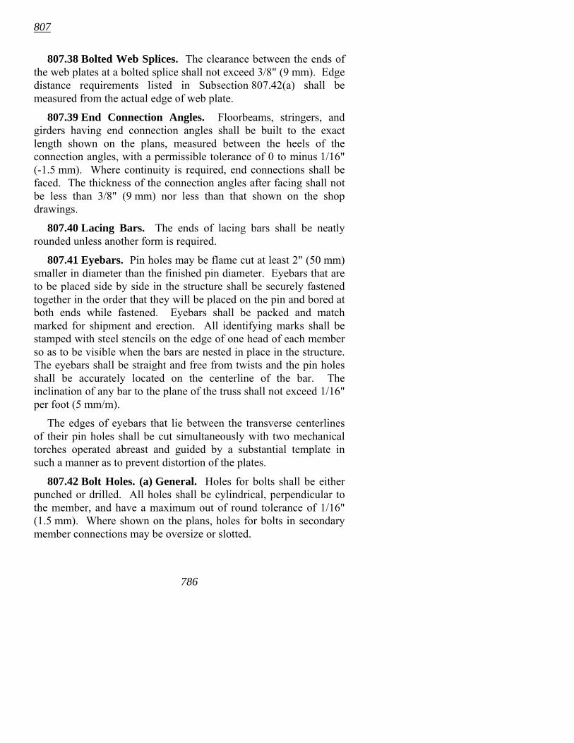
807
78
807.38 Bolted Web Splices. The clearance between the ends of the web plates at a bolted splice shall not exceed 3/8" (9 mm). Edge distance requirements listed in Subsection 807.42(a) shall be measured from the actual edge of web plate.
807.39 End Connection Angles. Floorbeams, stringers, and girders having end connection angles shall be built to the exact length shown on the plans, measured between the heels of the connection angles, with a permissible tolerance of 0 to minus 1/16" (-1.5 mm). Where continuity is required, end connections shall be faced. The thickness of the connection angles after facing shall not be less than 3/8" (9 mm) nor less than that shown on the shop drawings.
807.40 Lacing Bars. The ends of lacing bars shall be neatly rounded unless another form is required.
807.41 Eyebars. Pin holes may be flame cut at least 2" (50 mm) smaller in diameter than the finished pin diameter. Eyebars that are to be placed side by side in the structure shall be securely fastened together in the order that they will be placed on the pin and bored at both ends while fastened. Eyebars shall be packed and match marked for shipment and erection. All identifying marks shall be stamped with steel stencils on the edge of one head of each member so as to be visible when the bars are nested in place in the structure. The eyebars shall be straight and free from twists and the pin holes shall be accurately located on the centerline of the bar. The inclination of any bar to the plane of the truss shall not exceed 1/16" per foot (5 mm/m).
The edges of eyebars that lie between the transverse centerlines of their pin holes shall be cut simultaneously with two mechanical torches operated abreast and guided by a substantial template in such a manner as to prevent distortion of the plates.
807.42 Bolt Holes. (a) General. Holes for bolts shall be either punched or drilled. All holes shall be cylindrical, perpendicular to the member, and have a maximum out of round tolerance of 1/16" (1.5 mm). Where shown on the plans, holes for bolts in secondary member connections may be oversize or slotted.
6
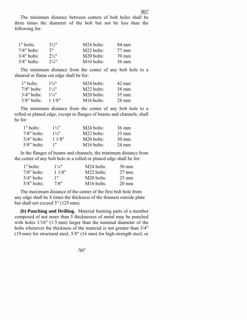
807
787
The minimum distance between centers of bolt holes shall be three times the diameter of the bolt but not be less than the following for:
1" bolts: 3½" M24 bolts: 84 mm 7/8" bolts: 3" M22 bolts: 77 mm 3/4" bolts: 2½" M20 bolts: 70 mm 5/8� bolts: 2¼" M16 bolts: 56 mm
The minimum distance from the center of any bolt hole to a sheared or flame cut edge shall be for:
1" bolts: 1¾" M24 bolts: 42 mm 7/8" bolts: 1½" M22 bolts: 38 mm 3/4" bolts: 1¼" M20 bolts: 35 mm 5/8� bolts: 1 1/8" M16 bolts: 28 mm
The minimum distance from the center of any bolt hole to a rolled or planed edge, except in flanges of beams and channels, shall be for:
1" bolts: 1½" M24 bolts: 36 mm 7/8" bolts: 1¼" M22 bolts: 33 mm 3/4" bolts: 1 1/8" M20 bolts: 30 mm 5/8� bolts: 1" M16 bolts: 24 mm
In the flanges of beams and channels, the minimum distance from the center of any bolt hole to a rolled or planed edge shall be for:
1" bolts: 1¼" M24 bolts: 30 mm 7/8" bolts: 1 1/8" M22 bolts: 27 mm 3/4" bolts: 1" M20 bolts: 25 mm 5/8� bolts: 7/8" M16 bolts: 20 mm
The maximum distance of the center of the first bolt hole from any edge shall be 8 times the thickness of the thinnest outside plate but shall not exceed 5" (125 mm).
(b) Punching and Drilling. Material forming parts of a member composed of not more than 5 thicknesses of metal may be punched with holes 1/16" (1.5 mm) larger than the nominal diameter of the bolts whenever the thickness of the material is not greater than 3/4" (19 mm) for structural steel, 5/8" (16 mm) for high-strength steel, or
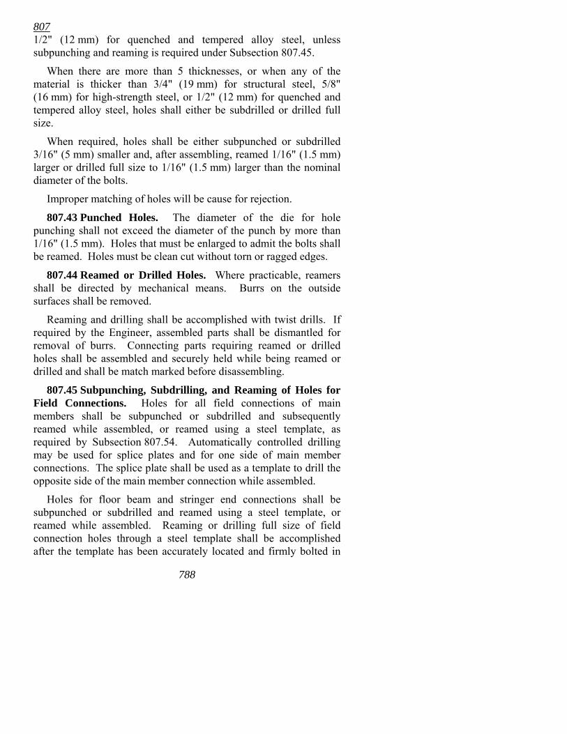
807
788
1/2" (12 mm) for quenched and tempered alloy steel, unless subpunching and reaming is required under Subsection 807.45.
When there are more than 5 thicknesses, or when any of the material is thicker than 3/4" (19 mm) for structural steel, 5/8" (16 mm) for high-strength steel, or 1/2" (12 mm) for quenched and tempered alloy steel, holes shall either be subdrilled or drilled full size.
When required, holes shall be either subpunched or subdrilled 3/16" (5 mm) smaller and, after assembling, reamed 1/16" (1.5 mm) larger or drilled full size to 1/16" (1.5 mm) larger than the nominal diameter of the bolts.
Improper matching of holes will be cause for rejection.
807.43 Punched Holes. The diameter of the die for hole punching shall not exceed the diameter of the punch by more than 1/16" (1.5 mm). Holes that must be enlarged to admit the bolts shall be reamed. Holes must be clean cut without torn or ragged edges.
807.44 Reamed or Drilled Holes. Where practicable, reamers shall be directed by mechanical means. Burrs on the outside surfaces shall be removed.
Reaming and drilling shall be accomplished with twist drills. If required by the Engineer, assembled parts shall be dismantled for removal of burrs. Connecting parts requiring reamed or drilled holes shall be assembled and securely held while being reamed or drilled and shall be match marked before disassembling.
807.45 Subpunching, Subdrilling, and Reaming of Holes for Field Connections. Holes for all field connections of main members shall be subpunched or subdrilled and subsequently reamed while assembled, or reamed using a steel template, as required by Subsection 807.54. Automatically controlled drilling may be used for splice plates and for one side of main member connections. The splice plate shall be used as a template to drill the opposite side of the main member connection while assembled.
Holes for floor beam and stringer end connections shall be subpunched or subdrilled and reamed using a steel template, or reamed while assembled. Reaming or drilling full size of field connection holes through a steel template shall be accomplished after the template has been accurately located and firmly bolted in
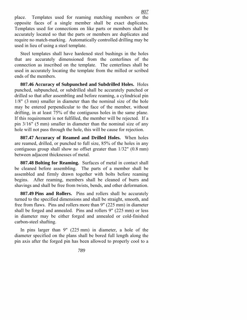
807
789
place. Templates used for reaming matching members or the opposite faces of a single member shall be exact duplicates. Templates used for connections on like parts or members shall be accurately located so that the parts or members are duplicates and require no match-marking. Automatically controlled drilling may be used in lieu of using a steel template.
Steel templates shall have hardened steel bushings in the holes that are accurately dimensioned from the centerlines of the connection as inscribed on the template. The centerlines shall be used in accurately locating the template from the milled or scribed ends of the members.
807.46 Accuracy of Subpunched and Subdrilled Holes. Holes punched, subpunched, or subdrilled shall be accurately punched or drilled so that after assembling and before reaming, a cylindrical pin 1/8" (3 mm) smaller in diameter than the nominal size of the hole may be entered perpendicular to the face of the member, without drifting, in at least 75% of the contiguous holes in the same plane. If this requirement is not fulfilled, the member will be rejected. If a pin 3/16" (5 mm) smaller in diameter than the nominal size of any hole will not pass through the hole, this will be cause for rejection.
807.47 Accuracy of Reamed and Drilled Holes. When holes are reamed, drilled, or punched to full size, 85% of the holes in any contiguous group shall show no offset greater than 1/32" (0.8 mm) between adjacent thicknesses of metal.
807.48 Bolting for Reaming. Surfaces of metal in contact shall be cleaned before assembling. The parts of a member shall be assembled and firmly drawn together with bolts before reaming begins. After reaming, members shall be cleaned of burrs and shavings and shall be free from twists, bends, and other deformation.
807.49 Pins and Rollers. Pins and rollers shall be accurately turned to the specified dimensions and shall be straight, smooth, and free from flaws. Pins and rollers more than 9" (225 mm) in diameter shall be forged and annealed. Pins and rollers 9" (225 mm) or less in diameter may be either forged and annealed or cold-finished carbon-steel shafting.
In pins larger than 9" (225 mm) in diameter, a hole of the diameter specified on the plans shall be bored full length along the pin axis after the forged pin has been allowed to properly cool to a
807
790
temperature below the critical range. Drilling shall be accomplished before the annealing process.
807.50 Boring Pin Holes. Pin holes shall be bored true to the specified diameter, smooth, straight, at right angles with the axis of the member, and parallel with each other unless otherwise specified. The final surface shall be produced by a finishing cut.
The distance outside to outside of end holes in tension members and inside to inside of end holes in compression members shall not vary from that specified more than 1/32" (0.8 mm). Boring of holes in built-up members shall be performed after fabrication is completed.
807.51 Pin Clearances. The diameter of the pin hole shall not exceed that of the pin by more than 1/50" (0.5 mm) for pins 5" (125 mm) or less in diameter or by 1/32" (0.8 mm) for larger pins.
807.52 Threads for Unfinished Bolts and Pins. Threads for bolts and pins for structural steel construction shall conform to the current Unified Standard Series UNC-ANSI B 1.1, Class 2A for external threads and Class 2B for internal threads, except that pin ends having a diameter of 1 3/8" (35 mm) or more shall be threaded 6 threads to 1" (6 threads to 25.4 mm).
807.53 Pilot and Driving Nuts. Two pilot nuts and two driving nuts for each size of pin shall be furnished, unless otherwise specified.
807.54 Shop Assembling. (a) General. The field connections of main members shall be assembled in the shop with milled ends of compression members in full bearing. After assembly, the sub-size holes shall be reamed to specified size.
(b) Assembly. Assembly shall be Full Truss or Girder Assembly unless Progressive Truss or Girder Assembly, Full Chord Assembly, Progressive Chord Assembly, or Special Complete Structure Assembly, is specified. The types of assembly are as described below.
(1) Full Truss or Girder Assembly. Full Truss or Girder Assembly shall consist of assembling all members of each truss, arch rib, bent, tower face, continuous beam line, plate girder, or rigid frame at one time.
807
791
(2) Progressive Truss or Girder Assembly. Progressive Truss or Girder Assembly shall consist of assembling initially for each truss, arch rib, bent, tower face, continuous beam line, plate girder, or rigid frame at least three contiguous shop sections, or all members in at least three contiguous panels but not less than the number of panels associated with three contiguous chord lengths (i.e., length between field splices), and not less than 150' (46 m) in the case of structures longer than 150' (46 m). At least one shop section or panel or as many panels as are associated with a chord length shall be added at the advancing end of the assembly before any member is removed from the rearward end so that the assembled portion of the structure is never less than that specified above. The assembly sequence for beams and girders shall include sufficient sections to include two bearings.
(3) Full Chord Assembly. Full Chord Assembly shall consist of assembling, with geometric angles at the joints, the full length of each chord of each truss or each leg of each bent or tower, then reaming the field connection holes while the members are assembled and reaming the web member connections using steel templates set at geometric (not cambered) angular relation to the chord lines.
At least one end of each web member shall be milled or scribed normal to the longitudinal axis of the member and the templates at both ends of the member shall be accurately located from one of the milled ends or scribed lines.
(4) Progressive Chord Assembly. Progressive chord assembly shall consist of assembling contiguous chord members in the manner specified for full chord assembly and in the number and length specified for progressive truss or girder assembly.
(5) Special Complete Structure Assembly. Special complete structure assembly shall consist of assembling the entire structure, including the floor system.
807.55 Drifting of Holes. The drifting accomplished during assembly shall be sufficient to bring the parts into position, but shall not enlarge the holes or distort the metal.
807.56 Match-Marking. Connecting parts that are assembled in the shop for the purpose of reaming field connection holes shall be
807
792
match-marked. A diagram showing such marks shall be furnished to the Engineer upon request.
807.57 Finished Members. Finished members shall be true to line and free from twists, bends, and open joints.
When finished members are moved to storage they shall be picked up at two or more points. They shall be carefully handled to prevent damage, and placed on skids above the ground. Long members shall be supported sufficiently to prevent damage from deflection.
807.58 Certification of Identification. The Contractor shall furnish an affidavit certifying that throughout the fabrication operation the identification of steel has been maintained according to this specification.
807.59 Storage of Materials. Structural material, either plain or fabricated, shall be stored above the ground upon platforms, skids, or other supports. It shall be kept free from dirt, grease, and other foreign matter, and shall be protected as far as practicable from corrosion. Handling of materials shall not cause damage or undue stress.
807.60 Weighing of Members. In case it is specified that any part of the material is to be paid for by actual weight, finished work shall be weighed in the presence of the Inspector. The Contractor shall supply satisfactory scales and shall perform all work involved in handling and weighing the various parts.
807.61 Marking and Shipping. Each member shall be printed or marked with an erection mark for identification. An erection diagram shall be furnished showing the appropriate erection marks. If steel die stamping is used for marking, it shall be the low stress type and high stress areas of members shall be avoided.
The Contractor shall furnish sufficient copies of material orders, shipping statements, and erection diagrams as the Engineer may direct. The weights of the individual members shall be shown on the statements. Members weighing more than 3 tons (3 metric tons) shall have the weights marked thereon.
Structural members shall be loaded on trucks or cars in such a manner that they may be transported and unloaded at their
807
793
destination without being excessively stressed, deformed, or otherwise damaged.
Bolts of each size, loose nuts or washers of each size, and fasteners tested as an assembly for rotational capacity tests shall be packed separately. A list and description of the contained material shall be plainly marked on the outside of each shipping container.
ERECTION
807.62 Erection of Steel Structures. When the substructure and superstructure are constructed under separate contracts, the Department will provide the substructure constructed to established lines and elevations and properly finished. When Bridge Construction Control is not included in the Contract, the Department will establish the lines and elevations required for erection of the superstructure steel.
The Contractor shall erect the structure steel, remove any designated temporary construction, and perform all work required to complete the structure or structures as provided in the Contract, including the removal of the old structure or structures when specified.
807.63 Methods and Equipment. Before starting the work of erection, the Contractor shall advise the Engineer, for informational and record purposes, of the method of erection he proposes to follow and the type of equipment he proposes for use. The Contractor shall be responsible for the safety of his methods and equipment and for performing the work according to the plans and specifications.
807.64 Falsework. Details of falsework construction for steel erection, complete with dimensions, design calculations, and kind and condition of materials, shall be submitted to the Engineer prior to construction for informational and record purposes. These details shall be prepared and/or approved by a Registered Professional Engineer. Construction shall be according to the details submitted to the Engineer for informational purposes. The Contractor shall be responsible for the results obtained by the use of the falsework design.
All falsework shall be designed and constructed to provide the necessary rigidity and to support the loads without appreciable
807
794
settlement or deformation. Falsework shall be set to give the finished structure the camber specified.
Falsework that cannot be founded on a satisfactory footing shall be supported on piling which shall be spaced, driven, and removed as specified in the Contractor's falsework details.
Upon completion of the steel erection the Contractor shall remove all falsework prior to placing the deck.
807.65 Handling and Storing Materials. Material to be stored shall be supported on skids above the ground. It shall be kept clean and properly drained. Girders and beams shall be placed upright and properly shored. Long members, such as columns and chords, shall be properly supported to prevent damage from deflection.
807.66 Bearings and Anchorage. Bearing plates shall not be placed upon bridge seat bearing areas that are improperly finished, deformed, or irregular. Bearing plates shall be set level and in the specified position and shall have uniform bearing on the masonry.
Bearing plates shall be accurately set on preformed fabric or elastomeric pads meeting the requirements of Subsection 807.15.
Anchor bolts shall be set in holes drilled in the bridge seat or cast in place. Bolts placed in drilled holes shall be accurately set and fixed with an approved epoxy or non-shrink grout from the QPL that completely fills the holes. The location of anchor bolts in relation to slotted holes in expansion shoes shall be determined by the air temperature and the amount of expansion at the time of erection. Nuts on anchor bolts at the expansion ends of spans shall be adjusted to permit free movement of the span.
807.67 Field Welding. All field welding shall be accomplished according to the applicable provisions of 807.26.
807.68 Straightening Bent Members and Correcting Camber. (a) Straightening Bent Members. Any member that is bent or distorted will be considered unacceptable until the member is either replaced or, if appropriate, repaired by a method proposed by the Contractor and approved by the Engineer. The straightening of plates, angles, other shapes, and built-up members, when permitted by the Engineer, shall be accomplished by methods that will not produce fracture or damage. Heat straightening of Grade 100 (690) steel members shall be accomplished only under rigidly controlled
807
795
procedures and each application shall be subject to the approval of the Engineer. In no case shall the maximum temperature of the Grade 100 (690) steel exceed 1100° F (590° C) nor shall the temperature exceed 950° F (510° C) at or within 6" (150 mm) of weld metal. Heat shall not be applied directly to weld metal. In all other steels, the temperature of the heated area shall not exceed 1150° F (620° C) as controlled by temperature-indicating crayons, liquids, or bi-metal thermometers.
Members to be heat straightened shall be substantially free of stress and from external forces other than stresses resulting from mechanical means used in conjunction with the application of heat. Members shall not be artificially cooled except as permitted in Subsection 807.27.
Following the straightening of a bend or distortion, the surface of the metal shall be carefully inspected for evidence of fracture. Such evidence will be cause for rejection.
(b) Correcting Camber. Correction of errors in camber in beams and girders shall be accomplished only under rigidly controlled procedures with each application of heat, subject to approval of the Engineer.
807.69 Assembling Steel. Steel members shall be accurately assembled as shown on the plans and match-marks shall be followed. Members shall be carefully handled so that no parts will be bent, broken, or otherwise damaged. Hammering which will damage or distort the members will not be allowed. Bearing surfaces and surfaces to be in permanent contact shall be cleaned before the members are assembled.
Unless erected by the cantilever method, truss spans shall be erected on blocking so as to give the trusses proper camber. The blocking shall be left in place until the tension chord splices are fully bolted and all other truss connections pinned and bolted. Permanent bolts in splices of butt joints of compression members and permanent bolts in railings shall not be tightened until the span has been made self-supporting.
Field connections using high strength bolts shall comply with the following assembly requirements:
• At least 4 erection pins, installed in extreme hole locations, shall be used. The actual number of erection pins required
807
79
shall be sufficient to ensure proper alignment of the remaining holes.
• A total of at least one half of the holes shall be filled with a combination of fitting-up bolts and the above required erection pins. At least 50% of this combination shall be fitting-up bolts. Fitting-up bolts shall be symmetrically placed.
For splices, the above requirements shall be applied to each element of the splice (i.e. top flange, web, bottom flange) on each side of the joint.
Fitting-up bolts may be either the same high strength bolts used for final assembly or they may be other bolts of the same nominal diameter as the high strength bolts. If non-high strength fitting-up bolts are used, they will be removed and replaced prior to the final assembly. Fitting-up bolts that are hammered into position shall not be used in the final assembly if thread damage has occurred. Erection pins shall be cylindrical and shall have a diameter 1/32" (0.8 mm) larger than the high strength bolts used in final assembly. The erection pins, as well as any fit-up bolts that are not part of the final assembly, shall be furnished by the Contractor at no cost to the Department.
807.70 Unfinished Bolt Connections. Unfinished bolts shall conform to the requirements of ASTM A 307, Grade A. Bolts shall have single self-locking nuts or double nuts unless otherwise specified. Beveled washers shall be used where bearing faces have a slope of more than 1:20 with respect to a plane normal to the bolt axis.
807.71 High Strength Bolt Connections. (a) General. High strength bolts meeting the requirements of AASHTO M 164 shall be furnished unless otherwise specified.
Bolts shall be placed with heads on the outside face of exterior girders and the bottom of girder flanges.
High strength fasteners, other than those used in bolted field splices for main load-carrying members, may be re-used one time after initial tightening to specification tension, provided that a close visual inspection indicates that there is no distress in the bolt, no damage to the threads, and that the nut runs freely on the bolt. When it becomes necessary to remove or loosen a bolt assembly
6
807
797
after it has been tightened to specification tension twice, the assembly must be discarded and a new one substituted.
High strength fasteners used in bolted field splices for main load-carrying members may be tightened to specification tension only once.
Retightening previously tightened bolts that may have been loosened by the tightening of adjacent bolts will not be considered as re-use provided the retightening continues from the initial position and does not require greater rotation, including the tolerance, than that required by Table 807-1.
All fitting-up bolts shall be brought to a snug tight condition before installing and tightening the balance of high strength bolts. Snug tight is defined as the tightness that exists when the plies of the joint are in firm contact.
Following the initial snug tightening of the fitting-up bolts, the remaining holes shall be filled with high strength bolts and tightened to a snug tight condition. Erection pins and any fitting-up bolts not suitable for final assembly shall then be replaced with high strength bolts and installed to a snug tight condition. All bolts in the connection shall then be tightened to the specified tension.
Snug tightening and tightening shall progress systematically from the most rigid part of the joint to its free edges.
(b) Bolts, Nuts, and Washers. Bolts, nuts, and washers shall conform to the requirements of Subsection 807.06.
Bolts, nuts, and washers shall be shipped and stored in weather proof containers. Bolts and nuts shall be reasonably free of corrosion or other foreign material. The nut shall run freely on the thread, using a wax type lubricant if necessary.
Fasteners shall be protected from dirt and moisture at the job site. Only as many fasteners as are anticipated to be installed and tightened during a work shift shall be taken from protected storage. Fasteners not used shall be returned to protected storage at the end of the shift. Fasteners shall not be cleaned of lubricant that was present on delivery. Fasteners that accumulate rust or dirt shall be cleaned and re-lubricated prior to installation.
(c) Bolted Components. Beveled washers shall be used where bearing faces have a slope of more than 1:20 with respect to a plane
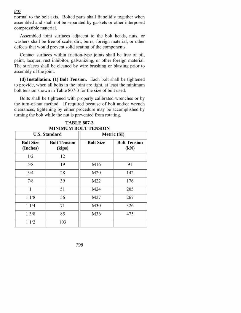
807
798
normal to the bolt axis. Bolted parts shall fit solidly together when assembled and shall not be separated by gaskets or other interposed compressible material.
Assembled joint surfaces adjacent to the bolt heads, nuts, or washers shall be free of scale, dirt, burrs, foreign material, or other defects that would prevent solid seating of the components.
Contact surfaces within friction-type joints shall be free of oil, paint, lacquer, rust inhibitor, galvanizing, or other foreign material. The surfaces shall be cleaned by wire brushing or blasting prior to assembly of the joint.
(d) Installation. (1) Bolt Tension. Each bolt shall be tightened to provide, when all bolts in the joint are tight, at least the minimum bolt tension shown in Table 807-3 for the size of bolt used.
Bolts shall be tightened with properly calibrated wrenches or by the turn-of-nut method. If required because of bolt and/or wrench clearances, tightening by either procedure may be accomplished by turning the bolt while the nut is prevented from rotating.
TABLE 807-3 MINIMUM BOLT TENSION
U.S. Standard Metric (SI)
Bolt Size (Inches)
Bolt Tension (kips)
Bolt Size Bolt Tension (kN)
1/2 12
5/8 19 M16 91
3/4 28 M20 142
7/8 39 M22 176
1 51 M24 205
1 1/8 56 M27 267
1 1/4 71 M30 326
1 3/8 85 M36 475
1 1/2 103
807
799
(2) Washers. Bolts shall have a hardened washer under the nut, and under the bolt head if turned in tightening.
(3) Turn-of-Nut Tightening. When the turn-of-nut method is used to provide the bolt tension specified in paragraph (d)(1) above, all bolts in the connection shall be tightened by the applicable amount of nut rotation specified in Table 807-1. During this operation there shall be no rotation of the part not turned by the wrench.
Following this initial operation, bolts shall be placed in any remaining holes in the connection and brought to snug tightness. All bolts in the joint shall then be tightened additionally by the applicable amount of nut rotation specified below. Tightening shall progress systematically from the most rigid part of the joint to its free edges. During this operation there shall be no rotation of the part not turned by the wrench.
(4) Calibrated Wrench Tightening. When calibrated wrenches are used to provide the bolt tension specified in paragraph (d)(1) above, their setting shall be such as to induce a bolt tension 5%-10% in excess of this value. Wrenches shall be of adequate capacity to perform the required tightening of each bolt in less than 10 seconds. These wrenches shall be calibrated at least once each working day by tightening, in a device capable of indicating actual bolt tension, not less than 3 typical bolts from each lot of 500 of the same grade, size, and condition of the bolts to be installed. Power wrenches shall be adjusted to stall or cut-out at the selected tension.
After the wrenches are adjusted to provide the required tension, the calibration selected shall be verified during actual installation of the assembled steel work to ensure that nut or bolt head rotation from snug tight is not greater than that permitted in Table 807-1, including the 30° tolerance.
If manual torque wrenches are used, the torque indication corresponding to the calibrating tension shall be noted and used in the installation of all bolts of the tested lot. When using calibrated wrenches to install several bolts in a single joint, the wrench shall be returned to "touch up" any bolts. "Touch up" shall continue until all bolts are tightened to the specified tension.
807
800
(e) Inspection. When the calibrated wrench method of tightening is used, the Engineer shall have full opportunity to witness the calibration tests prescribed in paragraph (d)(4) above.
The Engineer will observe the installation and tightening of bolts to determine that the selected tightening procedure is properly used and will determine that all bolts are tightened as specified.
Unless otherwise specified, the following inspection procedures will be used:
(1) The Contractor, in the presence of the Engineer, shall use an inspection wrench (either torque or power) that can be accurately adjusted according to the requirements of paragraph (d)(4) above.
(2) Three typical bolts from each lot of 500 of the same grade, size, and condition as those under inspection shall be individually placed in a calibration device capable of indicating bolt tension. There shall be a washer under the part turned in tightening each bolt.
(3) When the inspecting wrench is a torque wrench, each bolt specified in paragraph (e)(2) shall be tightened in the calibration device to the minimum tension specified for its size in paragraph (d)(1). The inspecting wrench then shall be applied to the tightened bolt and the torque necessary to turn the nut or head 5° (approximately 1" [25 mm] at 12" [300 mm] radius) in the tightening direction shall be determined. The average torque measured in the tests of three bolts shall be taken as the job inspecting torque to be used in the manner specified in paragraph (e)(5).
(4) When the inspecting wrench is a power wrench it shall be adjusted so that it will tighten each bolt specified in paragraph (e)(2) to a tension at least 5% but not more than 10% greater than the minimum tension specified for its size in paragraph (d)(1). This wrench setting shall be the job inspecting torque to be used in the manner specified in paragraph (e)(5).
(5) Bolts represented by the sample prescribed in paragraph (e)(2) and which have been tightened in the structure shall be inspected by applying the inspecting wrench and its job inspecting torque to 10% but not less than 2 of the bolts, selected at random, in each connection. If no nut or bolt head is turned by
807
801
this application of the job inspecting torque, the connection will be accepted as properly tightened. If any nut or bolt head is turned by the application of the job inspecting torque, this torque shall be applied to all bolts in the connection, and all bolts whose nut or head is turned by the job inspecting torque shall be tightened and reinspected, or alternatively, the Fabricator or Erector, at his option, may retighten all of the bolts in the connection and resubmit the connection for the specified inspection.
807.72 Pin Connections. Pilot and driving nuts shall be used in driving pins for connections. Pins shall be so driven that the members will take full bearing on them. Pin nuts shall be screwed up tight and the threads burred at the face of the nut with a pointed tool.
807.73 Misfits. The correction of minor misfits involving harmless amounts of reaming, cutting, and chipping will be considered a legitimate part of the erection. However, any error in the shop fabrication or deformation resulting from handling and transportation that prevents the proper assembling and fitting up of parts by the moderate use of drift pins or by a moderate amount of reaming and slight chipping or cutting, shall be reported immediately to the Engineer and his approval of the method of correction obtained. The correction shall be made in his presence. The Contractor shall be responsible for all misfits, errors, and injuries and shall make the necessary corrections and replacements.
807.74 Profiling of Steel Beams and Girders. Upon completion of erection and bolting of beams and girders, the Contractor shall profile each beam or girder line. The profiling shall be accomplished prior to beginning any deck forming operations. These profiles will be used to establish a finished deck elevation to provide the correct deck thickness. This may require the construction of variable haunches over the beams or girders to obtain the correct deck elevation and thickness. All required haunches are considered variable and the extra materials and work required in construction of these haunches shall be at no cost to the Department.
PAINTING
807
802
807.75 Painting -- General. The painting of metal structures shall include, unless otherwise provided in the Contract, the preparation of the metal surface and the application, protection, and drying of the paint coatings. All references to this subsection at other locations in these specifications shall be deemed to include Subsections 807.75 through 807.88, as applicable.
The prime and finish coats shall be the type and color specified in the Contract.
The Contractor shall exercise every reasonable precaution throughout the life of the project to prevent pollution of rivers, streams, or impoundments. Painting and cleaning operations conducted over or in the vicinity of water shall be controlled to prevent materials or waste, considered a contaminant by the Arkansas Department of Environmental Quality (ADEQ), from falling into the water. All material or waste that falls into the water, or onto areas where there is a likelihood that it will be picked up by rising water levels, shall be retrieved and properly disposed of in approved locations.
When paint is to be applied to a structure that spans a waterway, the Contractor shall notify the ADEQ, in writing, at least 2 weeks prior to the date work is to begin. A copy of this notification shall be furnished to the Engineer.
The Contractor shall protect pedestrian, vehicular, or other traffic upon, underneath, or in the vicinity of the bridge, and all portions of the bridge superstructure and substructure against damage or disfigurement by drift, spatters, splashes, or smirches of paint or paint materials.
All scaffolding, ladders, and other equipment, materials, or tools that restrict vertical or horizontal clearances shall be clear of all lanes and shoulders open to traffic when not in use or protected by appropriate traffic control devices.
807.76 Paint System. (a) General. The paint system shall consist of an Inorganic Zinc-Rich Prime Coat applied in the fabrication shop and a Finish System that shall be field applied. All coatings used shall be supplied by the same manufacturer to ensure compatibility. Lead and chromium pigments will not be permitted. All coatings shall meet the current EPA and ADEQ restrictions for Volatile Organic Compounds (VOC).
807
803
The Engineer will verify the thickness of each paint coat using a dry film thickness gauge. Dry film thickness will be determined by methods described by the Steel Structures Painting Council (SSPC). Any paint coat found to be deficient in thickness shall be corrected according to the manufacturer's recommendations. The correction shall be at no cost to the Department.
(b) Prime Coat. The prime coat shall be an inorganic zinc-rich paint meeting the material and composition requirements listed under Subsection 807.77. Prior to application of the prime coat, the steel shall be thoroughly blast cleaned according to Subsection 807.84(b). If rust forms after blast cleaning, the surface shall again be blast cleaned before painting. The minimum dry film thickness for the inorganic zinc-rich prime coat shall be 3.0 mils (75 µm).
(c) Finish System. The finish system shall be a two coat system composed of an epoxy tie coat and a coat of urethane paint meeting the material and composition requirements listed in Subsection 807.77. Neither the epoxy tie coat nor the urethane coat shall be applied until the preceding coat or any touch-up has cured for the minimum time as recommended by the manufacturer. The minimum dry film thickness of the epoxy tie coat shall be 2.0 mils (50 µm) unless otherwise recommended by the manufacturer. The minimum dry film thickness of the urethane coat shall be 3.0 mils (75 µm).
(d) Manufacturer and Brand Name Approval. Prior to approval of any paint, the following certified test reports shall be submitted to the Engineer of Materials for approval:
1) Certified test reports from an independent testing laboratory showing conformity with the slip coefficient requirement in Subsection 807.77(a)(1) for the inorganic zinc-rich primer. This test report shall show the manufacturer's name, brand name of the paint, and the date of manufacture of the paint used in the test, and shall certify that the paint used in the test meets all other requirements of Subsection 807.77(a).
2) Certified test reports from an independent testing laboratory for each paint showing compliance with
807
804
all other requirements of Subsection 807.77. The certified test reports shall show the manufacturer's name, brand name of the paint, date of manufacture, and the infrared spectrum analysis of the paint used in the tests. In addition, for two component paints the test reports shall show the exact ratio, by weight, of the pigment component to the vehicle component.
Upon approval by the Engineer of Materials of these certified test reports, no further testing will be required except as hereinafter noted. New certified test reports will be required whenever the manufacturing process, paint formulation, or source of raw materials is changed.
(e) Acceptance. The manufacturer shall furnish a certification for each lot certifying that the materials supplied conform to all the requirements specified and stating that the material is formulated the same as the material tested for manufacturer and brand name approval. All paints used for this application shall be listed on the QPL. Random samples may be taken and tested by the Department.
807.77 Materials. (a) Inorganic Zinc-Rich Primer. The prime coat shall be an inorganic zinc-rich paint complying with the requirements of AASHTO M 300 for Type I or Type II.
The paint shall qualify for a Class A classification (slip coefficient of 0.33 or greater) when tested according to "Testing Methods to Determine the Slip Coefficient for Coatings used in Bolted Joints", in Appendix A of Specification for Structural Joints Using ASTM A 325 or A 490 Bolts as published by AISC.
The manufacturer's current printed instructions for application of inorganic zinc-rich paint shall be submitted to the Engineer of Materials for approval prior to application.
(b) Finish System. The epoxy tie coat shall be the type as recommended by the manufacturer to ensure good bond between the inorganic zinc-rich prime coat and the urethane top coat. The epoxy tie coat and the urethane paint for the finish system shall be manufactured by the supplier of the inorganic zinc-rich paint. The urethane paint shall be a high build aliphatic polyurethane paint that is compatible with the previous coat. The urethane paint shall not blush or excessively chalk, and shall have the following properties:
807
805
(1) General. The high build aliphatic polyurethane paint shall be a two-component, weather resistant topcoat, containing no free oils, and having excellent resistance to splash and spillage of acids, alkalis, solvents, salts, and water. It shall provide adequate hiding when applied in a single coat over the epoxy tie coat.
The manufacturer will establish a typical density value and tolerance for each component and for the mixed paint. The mixed urethane paint shall have a solids content of not less than 57% by volume.
(2) Color. The color of the urethane paint shall match the Federal Standard 595A Color Chip No. 37200, Aluminum color, unless otherwise specified on the plans.
(c) Packaging and Labeling. Paint shall be packaged in new containers having resealable tops. Each container shall bear a label on which shall be clearly shown the name of the manufacturer, the kind of paint, the lot number, date of manufacture, net weight of contents, and equipment cleaning instructions. For two component paints, the label shall also show the mixing instructions.
807.78 Number of Coats. Steel shall receive one shop prime coat, one epoxy tie coat, and one field finish coat. Previously applied coats which have been damaged or skinned shall be corrected according to the manufacturer's recommendations prior to the application of any succeeding coat. The various coats shall be sufficiently different in color as to permit detection of incomplete application.
807.79 Mixing of Paint. Paint shall be mixed before applying in order to keep the pigments in uniform suspension.
Mechanical mixers shall be used to mix the paint. Prior to applying, the paint shall be mixed a sufficient length of time to thoroughly mix the pigment and the vehicle together, and it shall be kept thoroughly mixed during its application.
807.80 Thinning Paint. Paint shall be ready for use when thoroughly mixed. However, where thinning by addition of vehicle is recommended by the manufacturer, paint may be thinned according to those recommendations. The recommendations for thinning shall be plainly marked on the paint container and the minimum dry film thickness shall be achieved. The addition of thinner shall not exceed the allowable VOC established by ADEQ.
807
80
807.81 Weather Conditions for Painting. Paint shall be applied according to the temperature, humidity range, and other limitations recommended by the manufacturer. Paint shall not be applied when, in the opinion of the Engineer, conditions are unsatisfactory for the work. Paint shall not be applied upon a damp or frosted surface.
807.82 Application of Paint. (a) General. Painting shall be accomplished in a neat and professional manner. All paint shall be applied using suitable conventional spray or airless spray equipment. A uniform coating free from runs and sags shall be produced. Brushing may be used for touch-up or in areas inaccessible for spraying.
All surfaces to be painted shall be clean and free from dust, oil, grease, or other objectionable matter.
(b) Brushing. When brushes are used, the paint shall be so manipulated under the brush as to produce a smooth, uniform, even coating in close contact with the metal or with previously applied paint, and shall be worked into all corners and crevices.
(c) Spraying. Power spraying equipment shall apply the paint in a fine, even spray. Paint applied with spray equipment shall be immediately followed by brushing when necessary to secure uniform coverage and to eliminate wrinkling, blistering, and airholes.
(d) Inaccessible Surfaces. On surfaces that are inaccessible for brushes, the paint shall be applied by spraying or by using appropriate daubers.
807.83 Removal of Unsatisfactory Paint. If any painting application produces a coat that is unsatisfactory to the Engineer, the paint shall be removed and the metal thoroughly cleaned and repainted.
807.84 Cleaning Surfaces. (a) General. Surfaces of metal to be painted shall be thoroughly cleaned by removing rust, loose mill scale, dirt, oil, grease, and other foreign substances.
(b) Blast Cleaning. Blast cleaning shall be used for the preparation of steel surfaces prior to the application of the prime coat. Steel shall be cleaned by either the centrifugal wheel or the air blast method. Blast cleaning shall produce a surface preparation conforming to SSPC-SP10, Near-White Blast Cleaning with a
6
807
807
surface profile as recommended by the manufacturer of the paint. Blast cleaning shall include field contact surfaces of all bolted connections.
Special attention shall be given to the cleaning of corners and re-entrant angles. Before painting, metallic shot and grit or sand shall be removed from the surface. The cleaning shall be approved by the Engineer prior to painting. The material shall be painted before rust forms.
(c) Cleaning Prior to Topcoating. Prior to application of the epoxy tie coat and/or finish coat the surface to be painted shall be free of all dust, dirt, hardened concrete, oil, grease, and other foreign substances. The removal of dirt and hardened concrete shall be accomplished by the use of metal brushes, scrapers, chisels, hammers, or other effective means. Oil and grease shall be removed by the use of a suitable effective solvent. Bristle or wood fiber brushes shall be used for removing loose dust. Any paint damaged during cleaning shall be corrected according to the manufacturer's recommendations prior to application of succeeding coats.
(d) Surfaces Inaccessible After Fabrication. The inside surfaces of boxed members and other surfaces that will be inaccessible to the cleaning operation after fabrication shall be cleaned before assembly or cleaned by hand tool methods.
(e) Unpainted Weathering Structural Steel. Unless otherwise specified, Grade 50W (345W) structural steel that is not to be painted shall be blast cleaned to remove mill scale or other substances. Blast cleaning shall conform to SSPC-SP6, Commercial Blast Cleaning. Care shall be taken that dents, scratches, gouges, or identification marks will not appear on exposed surfaces. All steel is to remain in the unpainted condition and shall be handled so that it is kept free of all grease, oil, concrete, chalk marks, dirt, or any other foreign material that might affect the natural and uniform weathering of the steel.
Any foreign material that adheres to the steel during the fabrication or construction process that will inhibit the formation of the oxide film shall be removed as soon as practicable according to the SSPC Surface Preparation Specifications by one of the following four methods:
1) SSPC-SP1, Solvent Cleaning
807
808
2) SSPC-SP2, Hand Tool Cleaning 3) SSPC-SP3, Power Tool Cleaning 4) SSPC-SP7, Brush-off Blast Cleaning
807.85 Shop Painting. Unless otherwise specified, structural steel shall be given one shop coat of approved paint before it is shipped from the plant.
Surfaces that will not be exposed to the atmosphere in the final structure, and which will be inaccessible after assembly, erection, or placement of concrete shall be given a prime coat but will not require a finish coat. Field contact surfaces of bolted connections, including all components of bolted splices, shall receive a prime coat of paint in the shop.
A shop prime coat of paint shall be applied to the top of the top flanges of all beams and girders.
Structural steel that is to be field welded shall not be painted before the field welding is complete.
Unless otherwise specified, surfaces of iron and steel castings, either milled or finished, shall be painted.
With the exception of abutting joints and base plates, machine-finished surfaces shall be coated, as soon as practicable after being accepted, with a graphite dry film lubricant or other approved coating prior to removal from the shop.
Erection and weight marks shall be painted upon surface areas that have previously been painted with the shop coat. Material shall not be loaded for shipment until it has thoroughly dried, and in no case less than 24 hours after the paint has been applied.
807.86 Field Painting. When erection work is complete, any adhering rust, scale, dirt, oil, grease, or other foreign materials shall be removed as specified in Subsection 807.84.
All areas of prime coat and/or shop applied epoxy tie coat that have been damaged or are otherwise defective shall be corrected according to the manufacturer's recommendations prior to application of the finish system. Areas requiring a finish coat on which the prime and/or epoxy tie coat was not applied shall be cleaned and the required coats applied prior to application of the finish coat. All surfaces shall be free of any soluble residue or
807
809
excessive amounts of loose zinc before the finish or epoxy tie coat is applied.
All paint, including prime, epoxy tie coat, and urethane finish coat, shall be properly cured according to the manufacturer�s recommendations; and limitations on recoat time complied with. Subsequent coatings shall be applied as soon as practical after recoat requirements are met. When application of subsequent coatings is not done within the specified time, the previously applied coating may require additional surface preparation, subject to the manufacturer�s recommendations.
Epoxy tie coats and finish coats shall not be applied to the contact surfaces of bolted connections. Surfaces that will be inaccessible after erection and will be exposed to the atmosphere shall be painted with the applicable field coats prior to erection. When the paint applied for correcting the shop coat has thoroughly dried and the field cleaning has been satisfactorily completed, the required field coats shall be applied. Small cracks and cavities that were not sealed in a watertight manner by the field prime coat shall be filled with an additional application of field prime coat paint before the finish system is applied.
The following provision shall apply to the application of the field prime and the finish system: To secure a maximum coating on edges of plates, shapes, bolts, and other parts subjected to special wear, the edges shall first be coated with a longitudinal motion and the bolts with a rotary motion followed immediately by the general painting of the whole surface, including the edges and bolts.
If traffic produces an objectionable amount of dust, the Contractor shall, at no cost to the Department, settle the dust for the necessary distance on each side of the structure and take any other precautions necessary to prevent dust and dirt from coming in contact with surfaces to be painted or with freshly painted surfaces.
The application of the finish coat shall be deferred until adjoining concrete work has been placed and finished.
807.87 Preparing Galvanized Surfaces for Painting. When required, the painting of galvanized surfaces shall be deferred as long as possible to allow weathering of the surfaces.
Before painting, galvanized surfaces shall be prepared as follows:
807
810
All soil, concrete spatter, and other surface dirt shall be removed with a stiff brush, scraper, or other suitable means.
All surfaces shall be cleaned with alkaline detergents such as trisodium phosphate. Surfaces cleaned with detergents shall be thoroughly rinsed with hot water to remove alkaline residue. Solvents may be required to remove certain contaminants, including oil or grease. When solvents are used, special care shall be taken to assure proper ventilation and safe working conditions. Manufacturers' recommendations for the use of solvents shall be followed.
The use of gasoline, benzene, low-flash naphtha, or other highly volatile fluids, and the washing of galvanized surfaces with vinegar or other acids prior to painting will not be allowed.
As an alternative to detergent and solvent cleaning, sweep blasting of the galvanized surface will be permitted.
The field prime and finish system shall be applied according to Subsection 807.86.
807.88 Repairing Damaged Galvanized Coatings. Galvanizing that has been chipped off or damaged in handling, transporting, or welding shall be repaired by field galvanizing.
Field galvanizing shall be accomplished by the application of a paste composed of approved zinc powder and flux with a minimum amount of water. The areas to be coated shall be thoroughly cleaned, including removal of any slag on welds, before the paste is applied. The surface to be coated shall first be heated with a torch to a temperature sufficient that the metallics in the paste are melted when applied to the heated surface. Extreme care shall be taken to assure that surrounding surfaces are not damaged by the torch. The flux in the paste will cause a black residue on the surface of the coated parts. This black residue shall be removed by rinsing with water or wiping with a clean, damp cloth.
Other methods of repairs may be used as allowed by ASTM A 780, Repair of Hot-Dip Galvanized Coatings. Products used for repair shall be as listed on the Department's QPL or as approved by the Engineer.
Repair to damaged galvanized coatings shall be accomplished at no cost to the Department.
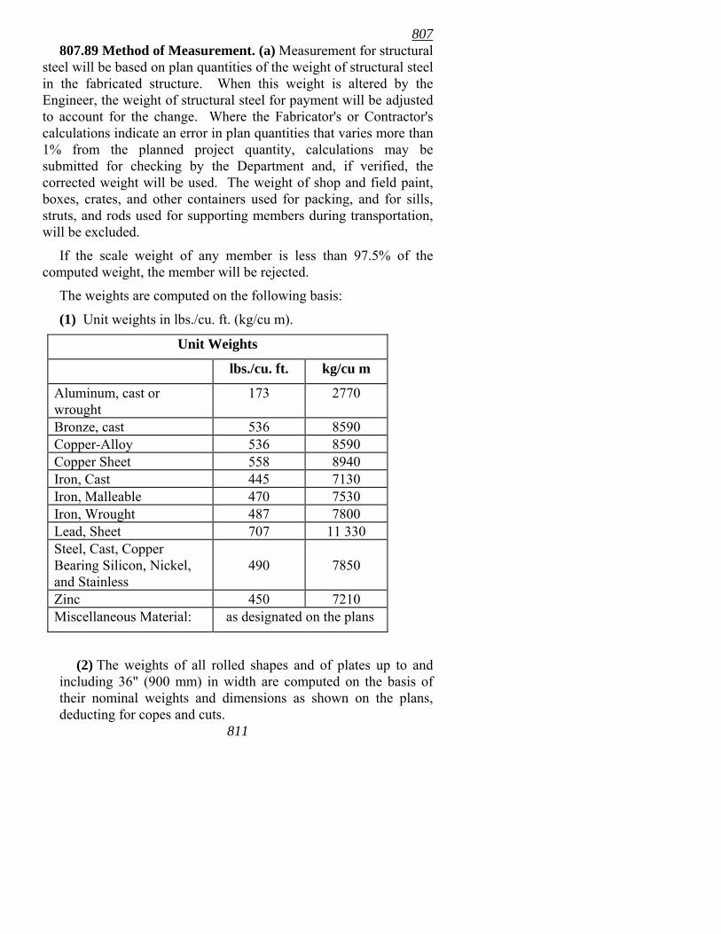
807
811
807.89 Method of Measurement. (a) Measurement for structural steel will be based on plan quantities of the weight of structural steel in the fabricated structure. When this weight is altered by the Engineer, the weight of structural steel for payment will be adjusted to account for the change. Where the Fabricator's or Contractor's calculations indicate an error in plan quantities that varies more than 1% from the planned project quantity, calculations may be submitted for checking by the Department and, if verified, the corrected weight will be used. The weight of shop and field paint, boxes, crates, and other containers used for packing, and for sills, struts, and rods used for supporting members during transportation, will be excluded.
If the scale weight of any member is less than 97.5% of the computed weight, the member will be rejected.
The weights are computed on the following basis:
(1) Unit weights in lbs./cu. ft. (kg/cu m).
Unit Weights
lbs./cu. ft. kg/cu m
Aluminum, cast or wrought
173 2770
Bronze, cast 536 8590 Copper-Alloy 536 8590 Copper Sheet 558 8940 Iron, Cast 445 7130 Iron, Malleable 470 7530 Iron, Wrought 487 7800 Lead, Sheet 707 11 330 Steel, Cast, Copper Bearing Silicon, Nickel, and Stainless
490
7850
Zinc 450 7210 Miscellaneous Material: as designated on the plans
(2) The weights of all rolled shapes and of plates up to and including 36" (900 mm) in width are computed on the basis of their nominal weights and dimensions as shown on the plans, deducting for copes and cuts.
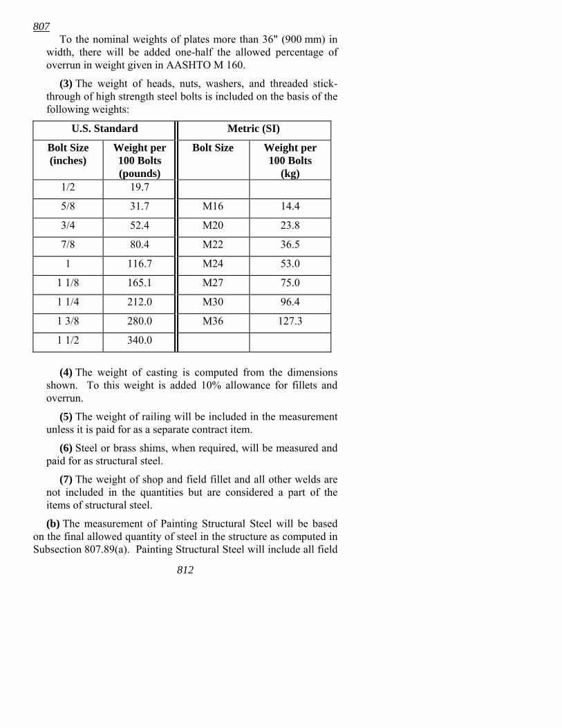
807
812
To the nominal weights of plates more than 36" (900 mm) in width, there will be added one-half the allowed percentage of overrun in weight given in AASHTO M 160.
(3) The weight of heads, nuts, washers, and threaded stick-through of high strength steel bolts is included on the basis of the following weights:
U.S. Standard Metric (SI)
Bolt Size (inches)
Weight per 100 Bolts (pounds)
Bolt Size Weight per 100 Bolts
(kg) 1/2 19.7
5/8 31.7 M16 14.4
3/4 52.4 M20 23.8
7/8 80.4 M22 36.5
1 116.7 M24 53.0
1 1/8 165.1 M27 75.0
1 1/4 212.0 M30 96.4
1 3/8 280.0 M36 127.3
1 1/2 340.0
(4) The weight of casting is computed from the dimensions
shown. To this weight is added 10% allowance for fillets and overrun.
(5) The weight of railing will be included in the measurement unless it is paid for as a separate contract item.
(6) Steel or brass shims, when required, will be measured and paid for as structural steel.
(7) The weight of shop and field fillet and all other welds are not included in the quantities but are considered a part of the items of structural steel.
(b) The measurement of Painting Structural Steel will be based on the final allowed quantity of steel in the structure as computed in Subsection 807.89(a). Painting Structural Steel will include all field
807 applied paint. Shop applied paint will not be measured or paid for separately, but full compensation therefor will be considered included in the contract unit price(s) bid for Structural Steel.
807.90 Basis of Payment. (a) Structural Steel. Work completed and accepted and measured as provided above, will be paid for at the contract unit price bid per pound (kilogram) for Structural Steel in Beam Spans, Structural Steel in Truss Spans, Structural Steel in Plate Girder Spans, or other classifications of metal for steel structures shown on the plans and in the proposal, as the case may be, which price shall be full compensation for furnishing materials; for fabrication, shop work including shop painting, transportation, falsework, erection, and repairing galvanizing; for performing quality control and acceptance sampling and testing; and for all labor, equipment, tools, and incidentals necessary to complete the work.
Unless otherwise provided, metal drains, bearing and expansion plates and shapes, and rockers and shoes will be paid for at the unit price bid for the structural steel for the spans on which this material is used.
(b) Painting Structural Steel. Work completed and accepted and measured as provided above will be paid for at the contract unit price bid per ton (metric ton) for Painting Structural Steel, which price shall be full compensation for furnishing materials; for cleaning and painting, including touch-up and repair of damaged shop paint; and for all labor, equipment, tools, and incidentals necessary to complete the work.
Payment will be made under:
Pay Item Pay Unit
Structural Steel in Beam Spans (___) Pound (Kilogram) Structural Steel in Truss Spans (___) Pound (Kilogram) Structural Steel in Plate Girder Spans (___) Pound (Kilogram) Painting Structural Steel Ton (Metric Ton)
SECTION 808 ELASTOMERIC BEARINGS
813
808 808.01 Description. This item shall consist of elastomeric
bearings and shall include unreinforced pads (consisting of Elastomer only) and reinforced bearings with steel lamina, furnished and constructed according to these specifications and the details shown on the plans.
808.02 Materials. Elastomeric bearings shall be supplied by a manufacturer listed on the QPL. The elastomer compound shall be of 100% virgin polychloroprene (neoprene) and shall meet the minimum requirements shown in Table 808-1. The testing methods given in Table 808-1 shall be used when determining material properties. When test specimens are cut from the finished product, a 10% variation in the physical properties indicated will be allowed.
Elastomers for steel reinforced bearings shall be 50-durometer hardness. Elastomers in unreinforced pads may be 50, 60, or 70-durometer hardness.
Steel lamina shall be rolled mild steel conforming to AASHTO M 270 Grade 36 [250] (except that Charpy V-Notch Impact tests are not required), ASTM A 1011, SS or HSLAS, or equivalent, shall have a minimum yield strength of 30,000 psi (205 MPa), and shall be ordered to the minimum nominal thickness specified on the plans.
External load plates shall conform to the requirements of AASHTO M 270, Grades 36 (250), 50 (345), or 50W (345W) as noted on the plans, except that Charpy V-Notch Impact tests are not required.
The vulcanized bond in reinforced bearings shall develop a minimum peel strength of 40 pounds per inch (6.9 kN/m). Peel strength tests shall be performed according to ASTM D429 Method B.
808.03 Fabrication. Bearings shall be furnished with the dimensions shown on the plans unless otherwise approved by the Engineer. Shop drawings for reinforced bearings shall be submitted to the Bridge Engineer and approval secured before fabrication is begun. Such drawings shall show the materials and fabrication procedures to be used, any changes from plan dimensions, and the bearing orientation and manner of marking the orientation when tapered external load plates are required. Unreinforced pads may be fabricated without submission or approval of shop drawings. Changes from plan dimensions proposed by the Contractor and
814
808 approved by the Engineer shall be at no additional cost to the Department.
Reinforced bearings shall be cast as a unit in a mold and shall be bonded and vulcanized under heat and pressure. The mold finish shall conform to standard shop practice. Internal steel lamina and surfaces of external load plates (sole plates and masonry plates) which are to be vulcanized shall be sandblasted and cleaned of all surface coatings, rust, mill scale, and dirt before bonding. Internal steel laminae shall be free of sharp edges and burrs and shall be sized to provide edge cover of ¼� (6 mm). External load plates (sole plates and masonry plates) shall be protected from rusting by the manufacturer and shall be vulcanized to the bearing pad during the primary molding process. Reinforced bearings shall be manufactured as a single unit.
Unreinforced pads may be molded or extruded, and vulcanized in large sheets and cut to size. Cutting shall not heat the materials, and shall produce a smooth finish to ANSI B46.1, 0.2 mils (0.006 mm). Unreinforced pads shall be molded or extruded to the finished thickness. Plying pads of lesser thickness together to make pads of finished thickness will not be allowed.
Flash tolerance, finish, and appearance shall meet the requirements of the latest edition of the Rubber Handbook as published by the Rubber Manufacturers Association, Inc., RMA F3 and T.063 for molded bearings and RMA F2 for extruded bearings.
808.04 Tolerances. Unreinforced pads, reinforced bearings, and external load plates shall be built to the design dimensions and these specifications with the following tolerances:
(a) Unreinforced pads and reinforced bearings: 1) Overall Vertical Dimensions
Design Thickness 1¼" (32 mm) or less -0, +1/8" (−0, +3 mm) Design Thickness over 1¼" (32 mm):...... -0, +1/4" (−0, +6 mm)
2) Overall Horizontal Dimensions 36" (1 m) and less:.................................... -0, +1/4" (−0, +6 mm) over 36" (1 m): ......................................... -0, +1/2" (−0, +12 mm)
815
808 3) Thickness of Individual Layers of
Elastomer Between Steel Lamina at any point within the bearing (Reinforced Bearings only) ...................... ± 1/8" (±3 mm)
4) Variations from a Plane Parallel to the Theoretical Surface (as determined by measurements at the edge of the bearings) Top:........................................................... Slope relative to
the bottom of no more than 0.005 radians
Sides: ........................................................ ± 1/4" (± 6 mm) 5) Cover of Embedded Lamina: ± 1/8" (± 3 mm) 6) Size of Holes, Slots, or Inserts:................. ± 1/8" (±3 mm) 7) Position of Holes, Slots, or Inserts:........... ± 1/8" (±3 mm)
(b) External load plates: 1) Overall Dimensions
Thickness:................................................. ±1/16" (± 2 mm) Length and Width: .................................... ± 1/4" (± 6 mm) Flatness:.................................................... 0.001 X nominal
dimension 2) Bevel Slope (top of plate relative to bottom of plate: Variation from theoretical slope as determined by measurements at edge of plate:......................................................... ± 0.002
X nominal dimension but not less than ± 1/32"(± 0.8 mm)
3) Size of Holes, Slots, or Inserts:................. ± 1/8" (± 3 mm) 4) Positions of Holes, Slots, or Inserts: ......... ± 1/8" (± 3 mm)
808.05 Lot Testing. Testing for meeting the requirements of Subsection 808.02 shall be performed by the manufacturer on each production lot of bearings.
For each lot of reinforced bearings, a randomly selected sample comprising at least 10 percent of the lot shall be compression tested
816
808 by the manufacturer. Each bearing shall be individually loaded to 1.5 times its maximum design load shown on the plans for a minimum period of 15 hours. If, during the test, the load falls below 1.3 times the maximum design load, the test duration shall be increased by the period of time for which the load is below this limit. The bearing shall be examined visually at the end of the test while it is still under load. If the bulging pattern suggests lamina parallelism, a layer thickness that is outside the specified tolerances, or poor lamina bond, the bearing shall be rejected. If there are three or more surface cracks that are greater than 0.08" x 0.08" (2 mm wide and 2 mm deep), the bearing shall be rejected.
If a sample fails any test required by this subsection, all bearings of that lot will be rejected, unless the manufacturer elects to test each bearing for the failing test(s) at no cost to the Department.
A lot is defined as a group of no more than 100 bearings which are manufactured from the same batch of elastomer, cured under the same conditions and are all the same size.
808.06 Visual Inspection and Proof Loading of Finished Bearings. Every bearing shall be inspected for compliance with dimensional tolerances and for overall quality of manufacture. In reinforced bearings, the edges of the internal steel lamina shall be protected everywhere from corrosion.
The manufacturer shall proof load each reinforced bearing individually with a compressive load equal to 1.5 times its maximum design load shown on the plans. The load shall be held constant for five minutes, removed, and reapplied for another five minutes. The bearing shall be examined visually while under the second loading. If the bulging pattern suggests lamina parallelism, a layer thickness that is outside the specified tolerances, or poor lamina bond, the bearing shall be rejected. If there are three or more separate surface cracks that are greater than 0.08" x 0.08" (2 mm wide and 2 mm deep), the bearing shall be rejected.
808.07 Certification and Marking. The manufacturer shall certify that each bearing satisfies these specifications and shall supply a certified copy of all test results, including the number of reinforced bearings that failed the proof load test. Certified mill certificates for internal steel lamina and external load plates shall also be supplied.
817
808 Each reinforced bearing shall be marked in indelible ink or
flexible paint. The marking shall consist of the orientation, the order number, lot number, bearing identification number, and elastomer type and grade number. Unless otherwise specified, the marking shall be on a face that is visible after erection of the bridge.
818
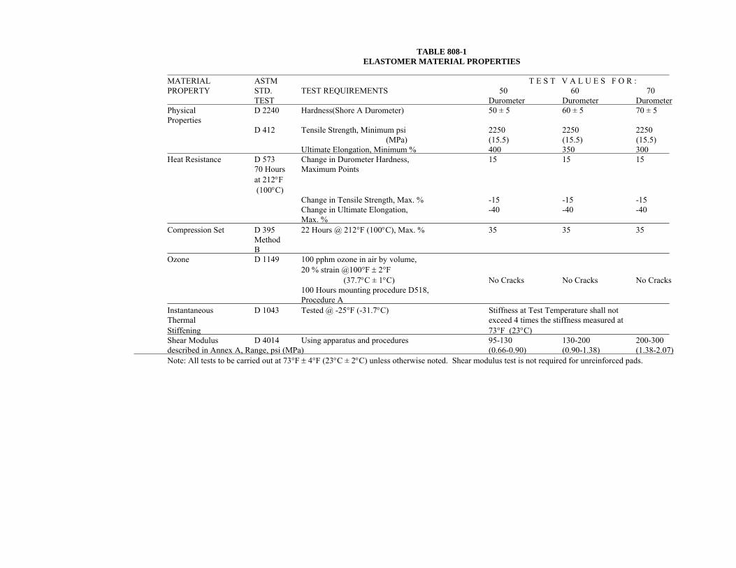
TABLE 808-1 ELASTOMER MATERIAL PROPERTIES
MATERIAL ASTM T E S T V A L U E S F O R : PROPERTY STD. TEST REQUIREMENTS 50 60 70 TEST Durometer Durometer Durometer Physical D 2240 Hardness(Shore A Durometer) 50 ± 5 60 ± 5 70 ± 5 Properties D 412 Tensile Strength, Minimum psi 2250 2250 2250 (MPa) (15.5) (15.5) (15.5) Ultimate Elongation, Minimum % 400 350 300 Heat Resistance D 573 Change in Durometer Hardness, 15 15 15 70 Hours Maximum Points at 212°F (100°C) Change in Tensile Strength, Max. % -15 -15 -15 Change in Ultimate Elongation, -40 -40 -40 Max. % Compression Set D 395 22 Hours @ 212°F (100°C), Max. % 35 35 35 Method B Ozone D 1149 100 pphm ozone in air by volume, 20 % strain @100°F ± 2°F (37.7°C ± 1°C) No Cracks No Cracks No Cracks 100 Hours mounting procedure D518, Procedure A Instantaneous D 1043 Tested @ -25°F (-31.7°C) Stiffness at Test Temperature shall not Thermal exceed 4 times the stiffness measured at Stiffening 73°F (23°C) Shear Modulus D 4014 Using apparatus and procedures 95-130 130-200 200-300 described in Annex A, Range, psi (MPa) (0.66-0.90) (0.90-1.38) (1.38-2.07) Note: All tests to be carried out at 73°F ± 4°F (23°C ± 2°C) unless otherwise noted. Shear modulus test is not required for unreinforced pads.
808
820
•
•
•
808.08 Installation. Reinforced bearings shall be placed on level, uniform surfaces. Any misalignment in the support shall be corrected to form a level surface. Bottom external load plates (masonry plates), when used, shall be set on unreinforced pads. Preformed fabric pads meeting the requirements of Subsection 807.15(a) may be used in lieu of unreinforced pads.
Unless otherwise approved by the Engineer, the external load plate at expansion bearings may be welded to the beam/girder only when:
the approximate average air temperature during the 24 hour period immediately preceding welding is between 40º F and 80º F (4º C and 27º C); and the slots in the external load plate are positioned to center on the anchor bolts; and no horizontal deformation of the elastomeric pad is evident.
If welding at other temperatures is required, the Engineer will provide adjustment data. In no case shall the elastomer or the bond be subjected to
temperatures higher than 400° F (204° C).
808.09 Method of Measurement. Reinforced elastomeric bearings will be measured by the cubic inch (cubic centimeter) of elastomer material, including required lamina. No deductions will be made for bolt holes. External load plates will not be measured or paid for separately but will be considered included in the contract unit price bid for Elastomeric Bearings.
Unreinforced pads will not be measured separately, but will be considered subsidiary to "Class S Concrete - Bridge."
The quantities shown on the plans will be considered as the final quantities and no further measurement will be made unless, in the opinion of the Engineer or upon evidence furnished by the Contractor, substantial variations exist between quantities shown on the plans and actual quantities due to changes in alignment, dimensions or apparent errors.
808.10 Basis of Payment. Work completed and accepted and measured as provided above will be paid for at the contract unit price bid per cubic inch (cubic centimeter) for Elastomeric Bearings,
809 which price shall be full compensation for furnishing materials; for fabrication; for installation; and for all labor, equipment, tools, and incidentals necessary to complete the work.
Payment will be made under:
Pay Item Pay Unit
Elastomeric Bearings Cubic Inch (Cubic Centimeter)
SECTION 809 PREFORMED JOINT SEAL
809.01 Description. This item shall consist of furnishing and installing preformed elastic joint seal of the sizes and shapes shown on the plans and according to these specifications.
809.02 Materials. (a) Seal. The joint seal shall be a preformed, cellular, elastic polychloroprene joint seal and shall be listed on the QPL. It shall be resistant to abrasion and oxidation and to oils, gasoline, salt, and other substances that may be spilled on or applied to the bridge roadway surface. The seal shall be in one piece for the full length of the joint, including vertical face and top of curbs.
The width of the seal shall be as shown on the plans and the depth of the seal shall be approximately equal to the uncompressed width of the seal.
The manufacturer or supplier shall submit a drawing showing proposed seal dimensions and tolerances, factory made splices, and the distance from roadway surface to seating lugs to provide clearance from surface to top of seal, to the Bridge Engineer for approval.
The seal shall conform to the requirements of AASHTO M 297.
Each lot of the joint seal shall be identified with the manufacturer's name or trade mark.
(b) Lubricant-Adhesive. The lubricant-adhesive shall be as recommended by the seal manufacturer. Each lot shall be identified with the manufacturer's name or trade mark.
809.03 Construction Requirements. Prior to seal installation, the joint opening shall be measured and the Contractor shall verify
821
809 that the seal size is correct for the joint opening as built. The seal shall be installed in a clean and dry joint by using specialized tools recommended by the seal manufacturer. It shall be thoroughly secured in place with an approved lubricant-adhesive that shall cover both sides of the seal over the full area in contact with the faces of the roadway joint. The adhesive may be applied to the contact surfaces of the joint or the seal or both. The seal shall be installed below the level of the roadway surface by approximately 1/4" (6 mm).
The seal may be installed immediately after the concrete curing period. Temperature limitations of the adhesive, as recommended by the manufacturer, shall be observed. Joints shall be clean and free of foreign material immediately prior to the installation of the seal.
809.04 Method of Measurement. Preformed Joint Seal will be measured by the linear foot (meter). The measurement will be along the top of the seal from end to end.
The quantities shown on the plans will be considered as the final quantities and no further measurement will be made unless, in the opinion of the Engineer or upon evidence furnished by the Contractor, substantial variations exist between quantities shown on the plans and actual quantities due to changes in alignment or dimensions or to apparent errors.
809.05 Basis of Payment. Work completed and accepted and measured as provided above will be paid for at the contract unit price bid per linear foot (meter) for Preformed Joint Seal, which price shall be full compensation for furnishing and installing all materials; and for all labor, equipment, tools, and incidentals necessary to complete the work.
Payment will be made under:
Pay Item Pay Unit
Preformed Joint Seal Linear Foot (Meter)
SECTION 810
822CLOSED CELL JOINT FILLER
810 810.01 Description. This item shall consist of furnishing and
installing closed cell joint filler according to the details shown on the plans and these specifications.
810.02 Materials. (a) General. The closed cell joint filler shall be a resilient and non-extrudable joint material listed on the QPL. It shall be manufactured by a process that produces a closed cell, cross-linked ethylene vinyl acetate, low density polyethylene copolymer material that is impermeable, weather resistant, wear resistant, and contains a UV stabilizer.
The adhesive used shall be according to the manufacturer's recommendation. The strength of the bond shall be greater than the joint material's tensile strength of 100 psi (690 kPa).
Each lot of joint filler and adhesive shall be identified with the manufacturer's name or trade mark.
(b) Physical Requirements. The material shall meet the requirements for ASTM D 1056, Type 2, Class B, Grade 2 (AASHTO T 42 Modified) and the following physical requirements:
(1) Compression Set - based on ASTM D 3575, Suffix B: not more than 9% after 24 hours at 73° F (23° C) and 24 hours recovery.
(2) Extrusion - based on AASHTO T 42: not more than 1/4" (6 mm).
(3) Expansion - When placed in a joint opening with neutral expansion or compression with surface preparation and bonding agent as recommended by the manufacturer, the joint material shall remain bonded and intact at a joint opening 25% greater than the neutral position.
(4) Elongation - based on ASTM D 3575, Suffix T: The material shall be capable of 200% elongation before breaking.
(5) Density - based on ASTM D 3575, Suffix W, Method A: not less than 42 nor greater than 2.6 to 3.2 pounds per cubic foot (51 kg/cu m).
(6) Water Absorption - based on AASHTO T 42: not more than 3% vol/vol.
(7) Tensile Strength - based on ASTM D 3575, Suffix T: 100 psi (690 kPa).
823
810 (8) Recovery - based on AASHTO T 42: 95% for an average
of specimens tested.
810.03 Dimensions and Permissible Variations. The preformed joint material shall be within a tolerance for depth of +10% to -5%, and width of +2% to -1% of the dimensions shown on the plans.
810.04 Construction Methods. Prior to filler installation, the joint opening shall be measured and the Contractor shall verify that the joint filler size is correct for the joint opening built. Surface preparation, mixing of the adhesive, and installation of the joint filler shall be according to the manufacturer's recommended construction methods and installation temperatures.
The joint material shall be furnished and installed in lengths that cover the width of the bridge deck completed under each phase or in the lengths specified on the plans. All direction changes in the joint material shall be accomplished by splicing. Splices shall be made using the heat welding method. The last 12" (300 mm) of joint filler adjacent to a splice shall not be bonded until after the splice has been made.
When a field splice is to be used the Contractor shall make a test field splice on two 6" (150 mm) samples and furnish the splice to the Engineer for testing. When tested in elongation, the test specimen shall fail in the base material and not in the splice. The Contractor shall not proceed with the field splice until a satisfactory test splice has been made and tested.
810.05 Method of Measurement. Closed Cell Joint Filler will be measured by the linear foot (meter) in place. The measurement will be made along the top surface of the joint filler from end to end.
The quantities shown on the plans will be considered as the final quantities and no further measurement will be made unless, in the opinion of the Engineer or upon evidence furnished by the Contractor, substantial variation exists between the quantity shown on the plans and the actual quantity due to changes in alignment or dimensions or to apparent errors.
810.06 Basis of Payment. Work completed and accepted and measured as provided above will be paid for at the unit price bid per linear foot (meter) for Closed Cell Joint Filler, which price shall be full compensation for furnishing and installing all materials; and for 824
811 all labor, equipment, tools, and incidentals necessary to complete the work.
Payment will be made under:
Pay Item Pay Unit
Closed Cell Joint Filler Linear Foot (Meter)
SECTION 811 SHEET PILES
811.01 Description. This item shall consist of furnishing and driving sheet piling according to these specifications and as shown on the plans, or as directed, and consists only of sheet piling that is to be left in place so that it becomes a part of the finished work.
811.02 Materials. Sheet piles shall be of new steel of the type and weight specified on the plans and shall comply with AASHTO M 202.
Welding for splices shall comply with Subsection 807.26.
Paint for sheet piles, when required, shall comply with Section 638.
811.03 Construction Requirements. Sheet piles in the completed structure shall be practically watertight at the joints. Unless otherwise provided, the tops of sheet piles that will remain exposed in the completed structure shall be a neat line. The elevation of this neat line shall be as shown on the plans or established by the Engineer.
Unless otherwise provided, sheet piles extending above the ground or water surface shall be protected by painting as specified in Section 638. This protection shall extend from an elevation 0.5 m (18") below the finished ground line or normal water surface to the top of the exposed sheet pile.
811.04 Method of Measurement. Sheet Piles will be measured by the linear foot (meter) of pile in the finished structure.
811.05 Basis of Payment. Work completed and accepted and measured as provided above will be paid for at the contract unit price bid per linear foot (meter) for Sheet Piles of the size specified, which price shall be full compensation for furnishing materials; for
825
811 driving; for building up or cutting off where necessary; for painting when required; and for all labor, equipment, tools, and incidentals necessary to complete the work.
Allowance for pile build-up and cut-off, where piles have been furnished according to the lengths shown on the plans or established by the Engineer, will be on the basis of 3 linear feet (1 m) of pile per splice for build-up, and 50% of cut-off length plus 1 linear foot (0.3 m) for cut-offs.
Payment will be made under:
Pay Item Pay Unit
Sheet Piles (___) Linear Foot (Meter)
SECTION 812 BRIDGE NAME PLATE
812.01 Description. This item shall include the furnishing and placing of bridge name plates according to these specifications and conforming to the locations and details shown on the plans.
812.02 Materials. Bridge name plates shall be cast bronze and shall be listed on the QPL. The material for bronze plates shall comply with the following chemical requirements:
Copper 80.0 to 89.0% Tin 3.0 to 15.0% Lead 0 to 3.0% Iron 0 to 0.25% Nickel 0 to 1.0% Sulfur 0 to 0.05% Zinc 0 to 5.0% Phosphorus 0 to 1.0% Antimony 0 to 0.75%
812.03 Construction Requirements. The type and location of the name plate required for each bridge will be designated on the plans.
812.04 Method of Measurement. Bridge Name Plates will be measured by the unit.
826
813 812.05 Basis of Payment. Work completed and accepted and
measured as provided above will be paid for at the contract unit price bid each for Bridge Name Plate of the type specified, which price shall be full compensation for furnishing materials and installing the plates; and for all labor, equipment, tools, and incidentals necessary to complete the work.
Payment will be made under:
Pay Item Pay Unit
Bridge Name Plate (Type___) Each
SECTION 813
DAMPPROOFING 813.01 Description. This item shall consist of a dampproofing
or plain waterproofing composed of a primer coat followed by one or more moppings of an asphalt coating according to these specifications and at locations shown on the plans. Other dampproofing systems may be used when approved by the Engineer.
813.02 Materials. Asphalt materials shall conform to the requirements of Section 815.
813.03 Construction Requirements. The surface to which the dampproofing coating is to be applied shall be cleaned of dirt and foreign material, and shall be dry.
Dampproofing shall not be applied in wet weather or when the atmospheric temperature is below 50°F (10°C).
Priming of concrete, steel, or other surfaces shall be accomplished immediately before applying the first mopping. Additional moppings, when required by the plans, shall be applied soon after the preceding mopping has cooled.
The amount of asphalt in each mopping shall be not less than 2½ gallons per 100 square feet (1 L/sq m). Care shall be taken to avoid overheating the asphalt. The temperature of the asphalt at the time of application shall be in the range recommended by the manufacturer. Asphalt heating kettles shall be equipped with armored or electronic sensing, digital readout thermometers so
827
815 placed that the temperature of the asphalt can readily be determined at any time.
Care shall be taken to confine mopping only to the areas to be waterproofed and to prevent discoloration of other parts of the structure from dripping or spreading of the asphalt materials.
813.04 Method of Measurement. Dampproofing will be measured by the square foot (square meter). The area for measurement will be the entire finished area actually covered, but shall not exceed the limits shown on the plans or authorized by the Engineer.
813.05 Basis of Payment. Work completed and accepted and measured as provided above will be paid for at the contract unit price bid per square foot (square meter) for Dampproofing, which price shall be full compensation for furnishing materials; and for all labor, equipment, tools, and incidentals necessary to complete the work.
Payment will be made under:
Pay Item Pay Unit
Dampproofing Square Foot (Square Meter)
SECTION 814 VACANT
SECTION 815 MEMBRANE WATERPROOFING
815.01 Description. This item shall consist of the application of a membrane waterproofing, consisting of a membrane of the type designated, according to these specifications and in conformity with the plans.
815.02 Types of Membranes. The membrane shall consist of one of the following types:
Type A. One asphalt primer coat, two layers of asphalt-treated cotton fabric, and three moppings of asphalt.
828
815 Type B. One asphalt primer coat, two layers of asphalt-treated
felt, one middle layer of asphalt-treated cotton fabric, and four moppings of asphalt.
Type C. A 4 mil (0.10 mm) (minimum) polyethylene film laminated to a rubberized asphalt mastic material (total thickness of 50 mils [1.3 mm], minimum). A primer shall be used as specified by the manufacturer and a rubberized asphalt mastic shall be used for sealing seams and exposed edges.
Type D. One-part, cold applied, asphalt modified, urethane coating. Final cured thickness of this membrane shall be approximately 50 mils (1.3 mm) (multiple applications may be required to obtain this final cured thickness). This material shall not be used with asphalt impregnated joint filler.
Type E. Two layers of trowel applied, fiber-modified asphalt compound, either solvent based or a mineral colloid emulsion, and one layer of asphalt-treated cotton fabric placed between the layers of the modified asphalt.
Other types of membrane may be used subject to the approval of the Engineer.
When the type is not specified on the plans or in the Special Provisions, the Contractor may select any of the above types of membrane.
815.03 Materials. (a) Asphalt. Asphalt shall be mopped-on material and shall be the same type of asphalt as that with which the felt or fabric is treated.
(1) Asphalt Primer. Asphalt primer for use with asphalt for waterproofing, either above or below ground, shall conform to ASTM D 41.
(2) Asphalt for Mopping Above Ground. Asphalt for mopping above ground shall conform to ASTM D 449 for Type III Asphalt.
(3) Asphalt for Mopping Below Ground. Asphalt for mopping below ground shall conform to ASTM D 449 for Type I Asphalt.
(b) Fabric. Fabric shall conform to ASTM D 173.
829
815 (c) Felt. Felt shall consist of rag felt conforming to
ASTM D 226, Type II.
(d) Insulating Paper. Insulating paper shall be waterproof paper approximately 36" (1 m) wide, weighing not less than 10 pounds per 100 square feet (0.5 kg/sq m).
(e) Self-adhering polyethylene (Type C membrane) shall have a protective sheeting for the adhesive surface until ready for use. Primer and mastic used shall be as specified by the manufacturer.
(f) The one-part, moisture curing, cold applied, modified polyurethane shall be trowel applied. The material shall not evidence any lumping or skinning or any separation of pigments or fillers that cannot be easily redispersed by stirring. On a vertical surface there shall be no flow or sag of a 30 mil (0.8 mm) thick coating.
(g) The trowel applied, fiber-modified, solvent based, asphalt compound shall meet requirements of ASTM D 4586; the mineral colloid emulsion asphalt shall meet the requirements of ASTM D 1227, Type IV.
(h) Labeling and Delivery. All materials shall be delivered to the work in the original packages bearing the manufacturer's brand or label. The kind of material and the purpose for which it is to be used shall be indicated on the label.
815.04 Construction Requirements. At the time of application, surfaces to be membrane waterproofed shall be dry and clean and the temperature of the surface shall not be less than 50°F (10°C). Projections shall be removed. There shall be no punctures, depressions, pockets, or folds in the horizontal surfaces of the finished waterproofing.
Concrete curing requirements shall be completed before the waterproofing is applied.
On vertical surfaces, the strips of fabric or felt may be laid vertically. On sloping surfaces, the strips shall be placed shingle fashion, beginning at the lowest part of the surface to be waterproofed. Sufficient fabric or felt shall be allowed for a suitable lap or anchorage at the upper edge of the surface to be waterproofed. Side laps shall not be less than 2" (50 mm) and end laps shall be
830
815 staggered with laps not less than 12" (300 mm) or as recommended by the manufacturer.
Surfaces to be waterproofed with Types A or B membranes shall be given one coat of asphalt primer before the first mopping. The primer shall be applied to the surface to give a uniform coating. The prime coat shall be applied approximately 24 hours before applying the waterproofing membrane and shall be dry before the first mopping is applied.
Surfaces to be waterproofed with Types A or B membranes shall be mopped in sections. While the first mopping of asphalt is still hot, a strip of fabric or felt shall be placed on the mopping and pressed into place. Each mopping thereafter shall be applied so that it will completely cover and seal the fabric or felt. The amount of asphalt used for each mopping shall be not less than 4½ gallons per 100 square feet (1.8 L/sq m) of surface. Asphalt heating kettles shall be equipped with armored or electronic sensing, digital readout thermometers so placed that the temperature of the asphalt can be readily determined at any time.
The temperature at the time of application shall be in the range recommended by the manufacturer.
Patching shall not be accomplished without permission of the Engineer. Where patching is permitted for repair of defective waterproofing, it shall extend at least 12" (300 mm) beyond the outermost edge of the defective area. Each succeeding ply of the patch shall extend at least 3" (75 mm) beyond the preceding ply.
At construction joints, where specified, the primer (if required) shall be omitted for a width of 18" (500 mm) of the surface and a strip of insulating paper laid thereon before waterproofing is applied.
815.05 Method of Measurement. Membrane Waterproofing will be measured by the square foot (square meter). The area for measurement will be the entire finished surface area actually covered but shall not exceed the limits shown on the plans or authorized by the Engineer.
831
816
832
815.06 Basis of Payment. Work completed and accepted and measured as provided above will be paid for at the contract unit price bid per square foot (square meter) for Membrane Waterproofing of the type specified, which price shall be full compensation for furnishing and applying materials; and for all labor, equipment, tools, and incidentals necessary to complete the work.
Payment will be made under:
Pay Item Pay Unit
Membrane Waterproofing (Type___) Square Foot (Square Meter)
SECTION 816 FILTER BLANKET AND RIPRAP
816.01 Description. This item shall consist of a protective layer of riprap of the type specified, placed according to these specifications, and to the line, grade, thickness, and location shown on the plans or as directed.
816.02 Materials. (a) Stone. Stone for filter blanket and riprap shall be obtained from an approved source and shall consist of sandstone, limestone, or other hard and durable stone that will be resistant to the action of air and water. Riprap stone shall consist of field stone or quarry stone with angular or fractured faces, weighing not less than 140 pounds per solid cubic foot (2200 kg per solid cubic meter). As an alternate to stone, steel slag from an approved source and with the same weight requirements as above may be used. Material for filter blanket and riprap shall be hard and durable and from a source with a percent of wear not greater than 45 by the Los Angeles Test (AASHTO T 96).
(1) Filter Blanket. Filter blanket material shall contain no organic matter nor soft, friable particles in quantities considered objectionable by the Engineer, and shall consist of sand, gravel, crushed stone, or steel slag, reasonably well graded from coarse to fine according to the following gradation requirements:
816
833
SIEVE SIZE, (mm) PERCENT PASSING
2" (50 mm) 100 #4 (4.75 mm) 25-65 #200 (0.075 mm)) 0-12
In lieu of the material described above, material conforming to the grading requirements of Section 303 for Aggregate Base Course, Class 4, may be used.
(2) Dumped Riprap. Dumped riprap shall be reasonably free of fines and reasonably well graded between the maximum and minimum rock sizes so as to produce a minimum of voids. In general, the maximum piece size shall be not greater than 18" (0.5 m) in any dimension and approximately 50% of the material shall consist of pieces weighing 35 pounds (15 kg) or more.
Broken concrete conforming to the above requirements may be used in lieu of dumped riprap when specified on the plans or approved by the Engineer. Broken concrete material shall be free of protrusions of reinforcing steel.
(3) Foundation Protection Riprap. Pieces of stone or steel slag for foundation protection riprap shall range in size from approximately 35 pounds to 300 pounds (15 kg to 140 kg) each, and shall be graded from coarse to fine in such manner as to produce a minimum of voids.
(b) Concrete. Concrete for concrete riprap shall comply with the requirements of Section 802 for Class A concrete. The Contractor shall perform quality control and acceptance sampling and testing in accordance with Subsection 802.06.
(c) Sacked Sand-Cement. Sand shall comply with the fine aggregate requirement of Subsection 802.02(b). Cement shall conform to Subsection 802.02(a). Water shall conform to Subsection 802.02(d).
(d) Reinforcing. Reinforcing steel for concrete riprap, unless otherwise specified, shall be 6" x 6" W3 x W3 (150 mm x 150 mm MW19 x MW19) welded wire fabric complying with the requirements of Subsection 804.02(b).
(e) Synthetic Fiber Fabric. A synthetic fiber geotextile fabric complying with the requirements of Subsection 625.02, Type 5 may
816
834
be used as a filter blanket under dumped riprap in lieu of a granular filter blanket material.
(4) Dumped Riprap (Grouted). Stone for dumped riprap shall meet the requirements for Dumped Riprap in (2) above, except that the pieces shall range in size from approximately 12″ (300 mm) and 24″ (600 mm) in any dimension, with the interstices filled with stone spalls and grouted with cement grout. The grout filler shall be composed of a mixture of one part portland cement and three parts sand, mixed with water to produce a workable consistency. The amount of water used shall be approved by the Engineer.
816.03 Construction Requirements. (a) General. Prior to placing filter blanket and riprap, the slopes shall be shaped as shown on the plans. When rock or hard shale is encountered at the toe of the slope, the riprap shall be keyed into this material at least the depth of the riprap.
(b) Filter Blanket. Granular filter blanket material shall be spread uniformly on the previously prepared and approved surface to the thickness and location shown on the plans. Placement of the material by methods that will cause segregation or cause damage to the surface will not be permitted. Compaction of filter blanket will not be required, but it shall be finished to present a reasonably even surface free from mounds or windrows.
When fabric is used in lieu of granular material, it shall be placed directly on the prepared surface. Fabric sections may be placed vertically or horizontally on the slope. Adjacent fabric sections shall be joined by overlapping a minimum of 2' (0.6 m) at the edges and pinning the overlapped strip with U-shaped wire pins, single shaped steel pins with metal disc heads, or similar fasteners. The fasteners shall be 6″ (150 mm) or more in length and shall hold the fabric firmly in place. Fasteners shall be inserted through both strips of overlapped fabric at intervals of approximately 4' (1.2 m) along the overlap. Additional pins shall be installed as necessary to prevent displacement of the fabric.
Fabric shall be overlapped in the direction of water flow. The fabric shall be turned down and buried approximately 12" (0.3 m) deep at the exterior limits.
No construction equipment will be permitted directly on the fabric.
816
835
•
•
•
(c) Dumped Riprap. Stone, broken concrete, or steel slag for dumped riprap shall be placed in such a manner as to produce a reasonably well graded mass of rock with the minimum practicable percentage of voids and shall be constructed to the lines and grades shown on the plans or as directed by the Engineer. Material shall be placed in such a manner as to avoid displacing the underlying material. The larger pieces shall be well distributed throughout the entire mass and the finished riprap shall be free from objectionable pockets of small or large pieces. Hand placing, to a limited extent, may be required, but only to the extent necessary to secure the results specified above. Placing riprap by dumping into chutes or by similar methods likely to cause segregation will not be permitted.
Riprap stone or steel slag shall not be deposited in a manner that will cause damage to the filter blanket. Any damage to fabric during placement of riprap shall be corrected by the Contractor at no cost to the Department prior to proceeding with the work. Damaged fabric shall be repaired by placing a piece of fabric large enough to cover the damaged area and overlapping and pinning according to Subsection 816.03(b).
Dumped riprap for locations designated on the plans for detours shall be constructed to the lines and dimensions shown on the plans and in accordance with the provisions above except that:
Synthetic fiber fabric shall be used in lieu of granular filter blanket material.
No toe excavation, as shown in the standard drawings, will be required.
Dumped riprap and synthetic fiber fabric shall be placed immediately after the detour embankment is constructed. The placement of any base material or pavement will not be permitted on the detour until the riprap has been placed on the detour slopes and approved by the Engineer.
Removal of the riprap and filter fabric after the detour is no longer needed will be measured and paid for as Unclassified Excavation under Section 210. Upon removal, salvaged riprap that meets the requirements of Subsection 816.02 will be paid for when reused in other areas which require the utilization of riprap.
(d) Concrete Riprap. Concrete for riprap shall be cast in place as shown on the plans. Except as modified herein, construction
816
83
shall conform to Section 802 with a minimum concrete slump of 1" (25 mm) permitted.
Excessive cutting, washing, or other damage to the slope shall be restored before placing the concrete, using mechanical tampers to obtain compaction according to the requirements of Subsection 210.10. Surfaces of the slopes and toe walls shall be moist when the concrete is placed.
Splices in any required wire mesh fabric reinforcement shall be lapped at least 6" (150 mm). At the edge of the riprap, the wire mesh shall not be less than 1" (25 mm) nor more than 3″ (75 mm) from the edge of the concrete, and shall have no wires projecting beyond the last member parallel to the edge of the concrete.
Reinforcement shall be properly supported throughout the placement of concrete to maintain its correct vertical position, according to Subsection 804.06.
Concrete riprap shall be placed in strips of dimensions as shown on the plans. When not designated on the plans, the concrete shall be placed in alternate vertical strips with the remaining strips being filled in later. The width of strips shall be 5' (1.5 m) with 1/4" (6 mm) transverse dummy grooves on 5' (1.5 m) centers for the entire length of the strip. The joints between strips shall be normal to the slope and shall be cold joints without filler. A 1/2" (12 mm) premolded joint filler shall be placed immediately adjacent to all fixed construction before placing the concrete.
After the concrete has been placed and consolidated to the dimensions specified, and after it has set sufficiently to avoid slumping, the surface shall be finished with a wooden float to a reasonably smooth and uniform surface. Curing shall be according to Subsection 802.17. Weep holes are to be provided as shown on the plans or as directed by the Engineer.
(e) Foundation Protection Riprap. Stone or steel slag shall be carefully dumped to ensure reasonable conformance with the thickness and dimensions as shown on the plans or as directed by the Engineer.
(f) Sacked Sand-Cement Riprap. Sand and cement for Sacked Sand-Cement riprap shall be mixed mechanically in the proportion of 15% cement to sand, measured by weight, and shall be mixed to a uniform color.
6
816
83
After the mixing has been completed, the sand and cement shall be placed in suitable fabric sacks of approximately 1 cubic foot (0.03 cubic meter) capacity. The sacks shall be filled, in general, to not over 3/4 full and shall be securely sewn or stapled to form a straight edge. Tying of sacks to form a knot will not be permitted.
Starting at the toe, the prepared sacks of sand-cement shall be bedded on the surface upon which they are placed with the sewn or stapled ends all in the same direction. Sacks shall be placed in horizontal courses and successive courses shall overlap preceding joints. The sacks shall be rammed and packed against each other and tamped to provide a uniform surface. Immediately after tamping, the sacked sand-cement shall be thoroughly wetted. Water for wetting shall not be applied under excessive pressure.
Sacked sand-cement riprap shall have an average thickness of 9" (225 mm) when in final position, unless otherwise specified on the plans.
(g) Dumped Riprap (Grouted). Dumped Ripap shall be placed in accordance with (c) above. The stones shall be thoroughly wetted immediately prior to applying the grout. The grout shall be thoroughly worked into the voids as the grout is deposited on the surface of the riprap. The stones shall then be brushed to expose the top surfaces. The grouted riprap shall then be cured in accordance with Subsection 501.05(l).
816.04 Method of Measurement. Filter Blanket and riprap will be measured according to the units of measure herein specified. Quantities shown on the plans for Filter Blanket, Dumped Riprap, Concrete Riprap, Sacked Sand-Cement Riprap, and Dumped Riprap (Grouted) will be considered as the final quantities and no further measurement will be made unless, in the opinion of the Engineer or upon evidence furnished by the Contractor, substantial variations exist between quantities shown on the plans and actual quantities due to changes in alignment or dimensions or to apparent errors, in which case the entire in-place quantity at the affected location(s) will be measured, with measurement being made parallel to the surface. Dumped Riprap, Concrete Riprap, Sacked Sand-Cement Riprap, and Dumped Riprap (Grouted) will be measured by the cubic yard (cubic meter). Filter Blanket will be measured by the square yard (square meter). Foundation Protection Riprap will be measured by the ton (metric ton).
7
816 816.05 Basis of Payment. Work completed and accepted and
measured as provided above will be paid for at the contract unit price bid per square yard (square meter) for Filter Blanket; per cubic yard (cubic meter) for the items Dumped Riprap, Concrete Riprap, Sacked Sand-Cement Riprap, and Dumped Riprap (Grouted); or per ton (metric ton) for Foundation Protection Riprap, which prices shall be full compensation for furnishing materials, including reinforcing steel when specified on the plans; for preparation of the slope; for excavation including toe trench and backfill; for performing mix designs, and quality control and acceptance sampling and testing for concrete riprap; for placing; and for all labor, equipment, tools, and incidentals necessary to complete the work.
Payment will not be made for excess thickness of material nor for material required to replace embankment lost due to untimely completion of the filter blanket and/or riprap.
In cases where the combined specific gravity of the material used for Foundation Protection Riprap exceeds 2.80, the quantity of material will be adjusted for payment by multiplying the quantity of the material used by a specific gravity of 2.80 and dividing by the higher specific gravity.
Payment will be made under:
Pay Item Pay Unit
Filter Blanket Square Yard (Square Meter) Dumped Riprap Cubic Yard (Cubic Meter) Concrete Riprap Cubic Yard (Cubic Meter) Foundation Protection Riprap Ton (Metric Ton) Sacked Sand-Cement Riprap Cubic Yard (Cubic Meter)
Dumped Riprap (Grouted) Cubic Yard (Cubic Meter)
SECTION 817 TIMBER BRIDGES
838
817 817.01 Description. This item shall consist of furnishing and
erecting untreated or treated lumber and timber and hardware for bridges according to these specifications, and conforming to the lines, grades, dimensions, and details shown on the plans. Timber piling, when required or used, shall be as specified in Section 818.
817.02 Materials. (a) Structural Lumber and Timber.
(1) Species of Wood. The standard commercial names of the species of woods recognized in these specifications are as follows:
Fir, Douglas (Coast) Oak, White, Includes: Fir, Douglas (Inland) White Oak Oak, Red, includes: Chestnut Oak Red Oak Post Oak Black Oak Bur Oak Southern Red Oak Overcup Oak Water Oak Swamp Chestnut Oak Willow Oak Swamp White Oak Scarlet Oak Live Oak Pin Oak Chinquapin Oak Shumard Red Oak Pine, Southern Yellow, includes: Swamp Red Oak Loblolly, Longleaf, Blackjack Oak Pitch, Pond, Shortleaf, Laurel Oak and Slash Pine Texas Red Oak
(2) Limitations of Use. Structural lumber and timber shall not be used without pressure impregnation of a preservative, unless otherwise provided on the plans or in the Special Provisions. Treated timber shall be Southern Yellow Pine or Douglas Fir.
(3) Grading and Dimensions of Structural Timber. Structural lumber and timber shall meet the grading and numerical stress value requirements as shown in Table 817-1.
No boxed heart pieces of Douglas fir or redwood shall be used in stringers, floor beams, caps, columns, sills, or rail posts. Boxed heart pieces are defined as timber so sawed that at any point in the length of a sawed piece, the pith (center) lies entirely inside the four faces.
839
817 There will be no heartwood requirements for lumber and
timber that is to be pressure treated, and the amount of sapwood will not be limited. Heartwood requirements for untreated lumber and timber will be designated on the plans or in the Special Provisions.
The timber sizes shown on the plans are nominal sizes unless otherwise noted.
(4) Timber Preservatives. Unless otherwise specified on the plans, the preservative furnished according to AWPA Standard C14 shall be one of the following:
Creosote Creosote-coal tar Creosote-petroleum Chromated copper arsenate Ammoniacal copper arsenate (Chemonite) Pentachlorophenol
(b) Steel Items. Bars, plates, and structural shapes shall be of steel conforming to the requirements of AASHTO M 270, Grade 36 (250), except that Charpy V-Notch Impact tests are not required.
(c) Castings. Castings shall conform to the current edition of the following specifications:
Steel - AASHTO M 103, Grade 65-35 (450-240), Class 2. Chromium Alloy - AASHTO M 163, Grade CH 10. Gray Iron - AASHTO M 105, Class No. 30B. Malleable - ASTM A 47 (A 47M), Grade No. 24018. (d) Hardware. Machine bolts, drift-bolts, and dowels may be
either wrought iron or medium steel. Washers may be cast-ogee or malleable castings, or shall be cut from medium steel or wrought iron plate, when specified.
Nails, spikes, bolts, dowels, washers, and lag screws shall be of standard form and may be non-galvanized unless otherwise specified. Galvanizing, when required, shall be according to AASHTO M232 or M298, Class 40 or 50.
(e) Timber Connectors. Timber connectors may be one of the following types: split ring, toothed ring, shear plate, claw plate, or spike grid. The split ring and the shear plate shall be installed in precut grooves as recommended by the manufacturer. The toothed ring and the spike grid shall be forced into the contact surfaces of
840
817 the timbers and joined by means of pressure equipment. Connectors of this type at a joint shall be embedded simultaneously and uniformly. The claw plate shall be installed by a combination of both methods, partially by precut grooving and partially by pressure. Other connectors may be furnished when approved by the Engineer.
(f) Paint for Non-galvanized Steel Items and Hardware. When specified, the exposed surfaces of all non-galvanized steel items and hardware shall be painted according to Section 638.
(g) Pitch. Pitch shall be Type I Coal Tar Bitumen (Pitch) conforming to AASHTO M 118.
817.03 Storage and Protection of Materials. Lumber and timber shall be stacked on supports at least 12" (0.3 m) above the ground surface to avoid absorption of ground moisture. Untreated lumber and timber shall be open-stacked and stripped to permit free circulation of air between the tiers and courses. When required by the Engineer, untreated material shall be protected from the weather with a suitable cover.
Treated lumber and timber shall be close-stacked to prevent warping or sagging. The ground underneath and in the vicinity of material stacks shall be kept reasonably clear of vegetation.
817.04 Preservative Treatment of Lumber and Timber.
(a) General. The treatment of lumber and timber shall meet the applicable requirements of the current edition of the AWPA, Standards C1 and C14.
(b) Inspection. Materials and processes used in the manufacture of treated lumber and timber shall be subject to inspection at the manufacturer's plant.
The Engineer reserves the right to inspect material after delivery and to reject material that does not comply with the requirements of the applicable specifications.
(c) Handling. Treated lumber and timber shall be carefully handled to prevent marring or damage. Peaveys, pikes, tongs, or hooks shall not be used.
841
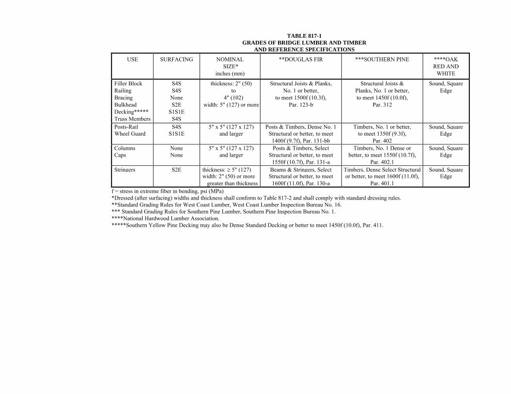
TABLE 817-1 GRADES OF BRIDGE LUMBER AND TIMBER
AND REFERENCE SPECIFICATIONS
USE SURFACING NOMINAL SIZE*
inches (mm)
**DOUGLAS FIR ***SOUTHERN PINE ****OAK RED AND
WHITE
Filler Block S4S thickness: 2" (50) Structural Joists & Planks, Structural Joists & Sound, Square Railing S4S to No. 1 or better, Planks, No. 1 or better, Edge Bracing None 4" (102) to meet 1500f (10.3f), to meet 1450f (10.0f), Bulkhead S2E width: 5" (127) or more Par. 123-b Par. 312 Decking***** S1S1E Truss Members S4S Posts-Rail S4S 5" x 5" (127 x 127) Posts & Timbers, Dense No. 1 Timbers, No. 1 or better, Sound, SquareWheel Guard S1S1E and larger Structural or better, to meet
1400f (9.7f), Par. 131-bb to meet 1350f (9.3f),
Par. 402 Edge
Columns None 5" x 5" (127 x 127) Posts & Timbers, Select Timbers, No. 1 Dense or Sound, SquareCaps None and larger Structural or better, to meet
1550f (10.7f), Par. 131-a better, to meet 1550f (10.7f),
Par. 402.1 Edge
Stringers S2E thickness: ≥ 5" (127) Beams & Stringers, Select Timbers, Dense Select Structural Sound, Square width: 2" (50) or more Structural or better, to meet or better, to meet 1600f (11.0f), Edge greater than thickness 1600f (11.0f), Par. 130-a Par. 401.1 f = stress in extreme fiber in bending, psi (MPa) *Dressed (after surfacing) widths and thickness shall conform to Table 817-2 and shall comply with standard dressing rules. **Standard Grading Rules for West Coast Lumber, West Coast Lumber Inspection Bureau No. 16. *** Standard Grading Rules for Southern Pine Lumber, Southern Pine Inspection Bureau No. 1. ****National Hardwood Lumber Association. *****Southern Yellow Pine Decking may also be Dense Standard Decking or better to meet 1450f (10.0f), Par. 411.
817
843
(d) Cutting, Framing, and Boring. Cutting, framing, and boring of treated lumber and timber shall be accomplished before treatment insofar as is practicable.
(e) Cuts, Abrasions, and Bolt Holes. Cuts, abrasions, and bolt holes in treated lumber and timber, after having been carefully trimmed, shall be covered with 2 applications of a mixture of 60% creosote oil and 40% roofing pitch, or brush coated with at least 2 applications of hot creosote oil and covered with hot roofing pitch.
(f) Temporary Attachment. When forms or temporary braces are attached to treated timber, any resulting holes shall be filled with galvanized or creosote covered nails or spikes or filled and plugged as required for bolt holes.
817.05 Construction Requirements. (a) Holes for Bolts, Pins, Dowels, Rods, and Lag Screws. Holes for drift pins and dowels shall be bored with a bit 1/16" (2 mm) less in diameter than the pin or dowel to be used.
Holes for machine bolts shall be bored with a bit the same diameter as the bolt. Holes for rods shall be bored with a bit 1/16" (2 mm) greater in diameter than the rod. Holes for lag screws shall be bored with a bit not larger than the body of the screw at the base of the thread.
Countersinking shall be accomplished wherever smooth faces are required. Horizontal recesses formed for countersinking shall be treated as specified in Subsection 817.04(e).
(b) Bolts and Washers. A washer, of the size and type specified, shall be used under all bolt heads and nuts that will come in contact with wood.
After tightening, nuts and bolts shall be effectively locked by burring the threads or other approved methods.
(c) Framing. Lumber and timber shall be accurately cut and framed to a close fit so that joints will have even bearing over the entire contact surfaces. Mortises shall be true to size for their full depth and tenons shall fit snugly. No shimming will be permitted in making joints and no open joints will be accepted.
(d) Framed Bents. (1) Concrete Pedestals. Concrete pedestals for the support of framed bents shall be carefully finished to provide even bearing. Dowels of not less than 3/4" (19 mm) diameter,
817
844
projecting at least 6" (150 mm) above the tops, shall be set in the pedestals for the anchoring of sills or columns.
(2) Sills. Sills shall have true and even bearing on piles or pedestals. They shall be drift-pinned to mud sills or piles with pins of not less than 3/4" (19 mm) diameter that extend at least 6" (150 mm) into the piles. When possible, earth shall be removed from contact with sills to provide for free circulation of air.
(3) Columns. Columns shall be fastened to pedestals with dowels of not less than 3/4" (19 mm) diameter, extending at least 6" (150 mm) into the columns.
Columns shall be fastened to sills by one of the following methods:
a. By dowels of not less than 3/4" (19 mm) diameter, extending at least 6" (150 mm) into the columns and sills.
b. By drift-pins of not less than 3/4" (19 mm) diameter driven diagonally through the base of the post and extending at least 9" (225 mm) into the sill.
(e) Caps. Caps shall be placed, with ends aligned, in a manner to provide even and uniform bearing over the tops of the supporting columns or piles. Caps shall be secured by drift-pins of not less than 3/4" (19 mm) diameter, extending at least 9" (225 mm) into the columns or piles. The drift-pins shall be approximately in the center of the column or pile.
(f) Bracing. The ends and intermediate intersections of bracing shall be bolted through the pile, column, or cap with a bolt of not less than 5/8" (16 mm) diameter.
(g) Stringers. Stringers shall be sized at bearings and shall be placed in position so that knots near the edges will be in the top portions of the stringers.
Exterior stringers may have butt joints with the ends cut on a taper. Interior stringers shall be lapped to take bearing over the full width of the floor beam or cap at each end. The lapped ends of untreated stringers shall be separated at least 1/2" (12 mm) for the circulation of air and shall be securely fastened by drift-pins where specified. Exterior and alternate stringers shall be securely fastened to the cap.
817
845
Cross-bridging between stringers shall be neatly and accurately framed and securely toe-nailed with at least two nails in each end. Cross-bridging members shall have full bearing at each end against the sides of stringers. Unless otherwise specified, cross-bridging shall be placed at the center of each span.
(h) Plank Floors. Single ply floors shall consist of a single layer of planking supported by stringers. Two ply floors shall consist of two layers of planking supported by stringers.
Planking for the surface layer of floors shall be placed transverse or diagonal to the centerline of the bridge. For two ply floors, the lower course of planking may be placed either transverse, longitudinal, or diagonal. Planks shall be carefully graded as to thickness and laid so that the differential of two adjacent planks in the finish surface shall be no more than 1/16" (2 mm).
Planks shall be laid heart side down, with 1/4" (6 mm) openings between them for seasoned material and with tight joints for unseasoned material. Each plank of a single ply floor and each plank of the lower layer of a two-ply floor shall be spiked to each stringer or floor beam. Each plank of the surface layer of a two-ply floor shall be spiked to each stringer using long spikes. Joints shall be staggered at least 3' (1 m).
(i) Laminated Floors. Lamina shall be placed on edge transverse to the centerline of the roadway. Each lamina shall be spiked to the preceding lamina at each end and at approximately 18" (0.5 m) intervals with the spikes driven alternately near the top and bottom edges. The spikes shall be of sufficient length to pass through two laminas and at least half way through the third lamina.
If timber supports are used, every other lamina shall be toe-nailed to every other support. If steel supports are used, the lamina shall be securely attached by the use of approved metal clips. Care shall be taken to have each lamina vertical and tight against the preceding one with bearing evenly distributed on all the supports.
(j) Wheel Guards and Railings. Wheel guards and railings shall be framed according to the plans and erected true to line and grade.
Unless otherwise specified, wheel guards shall be surfaced one side and one edge (S1S1E), and rails and rail posts shall be surfaced on four sides (S4S).
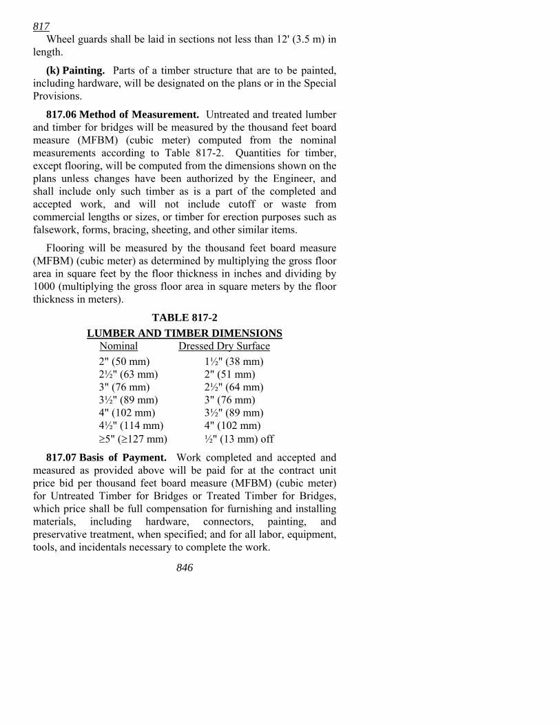
817 Wheel guards shall be laid in sections not less than 12' (3.5 m) in
length.
(k) Painting. Parts of a timber structure that are to be painted, including hardware, will be designated on the plans or in the Special Provisions.
817.06 Method of Measurement. Untreated and treated lumber and timber for bridges will be measured by the thousand feet board measure (MFBM) (cubic meter) computed from the nominal measurements according to Table 817-2. Quantities for timber, except flooring, will be computed from the dimensions shown on the plans unless changes have been authorized by the Engineer, and shall include only such timber as is a part of the completed and accepted work, and will not include cutoff or waste from commercial lengths or sizes, or timber for erection purposes such as falsework, forms, bracing, sheeting, and other similar items.
Flooring will be measured by the thousand feet board measure (MFBM) (cubic meter) as determined by multiplying the gross floor area in square feet by the floor thickness in inches and dividing by 1000 (multiplying the gross floor area in square meters by the floor thickness in meters).
TABLE 817-2 LUMBER AND TIMBER DIMENSIONS Nominal Dressed Dry Surface 2" (50 mm) 1½" (38 mm) 2½" (63 mm) 2" (51 mm) 3" (76 mm) 2½" (64 mm) 3½" (89 mm) 3" (76 mm) 4" (102 mm) 3½" (89 mm) 4½" (114 mm) 4" (102 mm) ≥5" (≥127 mm) ½" (13 mm) off
817.07 Basis of Payment. Work completed and accepted and measured as provided above will be paid for at the contract unit price bid per thousand feet board measure (MFBM) (cubic meter) for Untreated Timber for Bridges or Treated Timber for Bridges, which price shall be full compensation for furnishing and installing materials, including hardware, connectors, painting, and preservative treatment, when specified; and for all labor, equipment, tools, and incidentals necessary to complete the work.
846
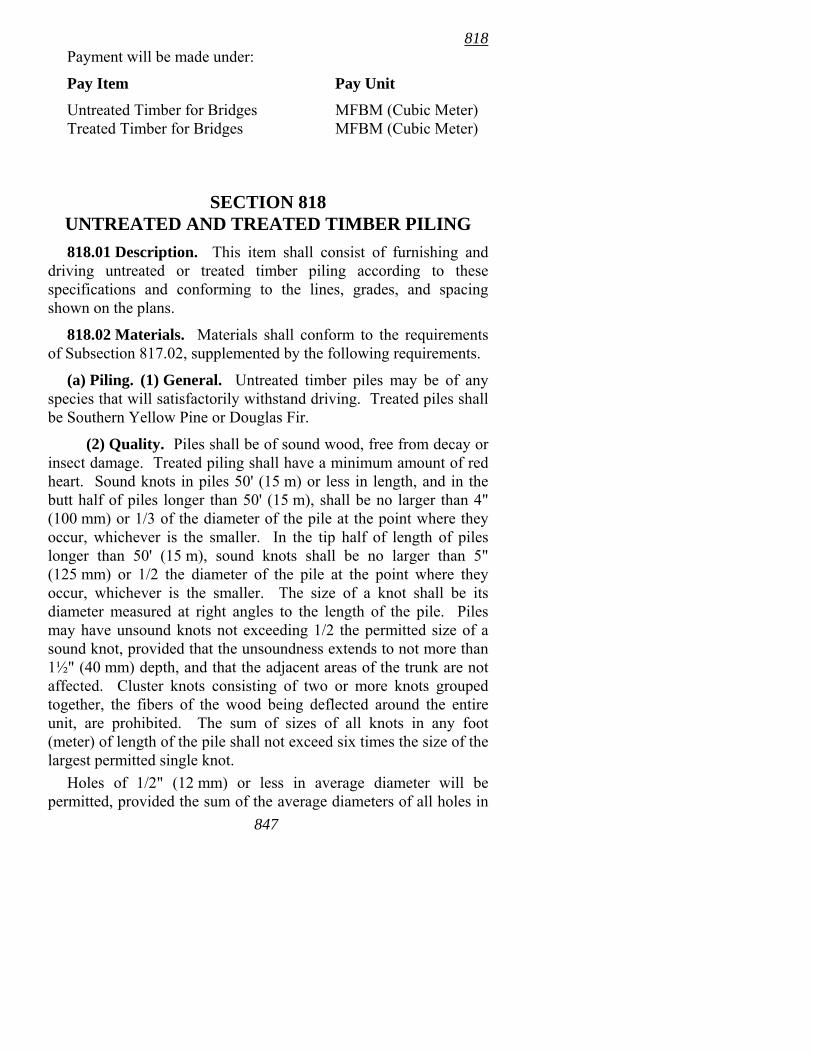
818 Payment will be made under:
Pay Item Pay Unit
Untreated Timber for Bridges MFBM (Cubic Meter) Treated Timber for Bridges MFBM (Cubic Meter)
SECTION 818
UNTREATED AND TREATED TIMBER PILING 818.01 Description. This item shall consist of furnishing and
driving untreated or treated timber piling according to these specifications and conforming to the lines, grades, and spacing shown on the plans.
818.02 Materials. Materials shall conform to the requirements of Subsection 817.02, supplemented by the following requirements.
(a) Piling. (1) General. Untreated timber piles may be of any species that will satisfactorily withstand driving. Treated piles shall be Southern Yellow Pine or Douglas Fir.
(2) Quality. Piles shall be of sound wood, free from decay or insect damage. Treated piling shall have a minimum amount of red heart. Sound knots in piles 50' (15 m) or less in length, and in the butt half of piles longer than 50' (15 m), shall be no larger than 4" (100 mm) or 1/3 of the diameter of the pile at the point where they occur, whichever is the smaller. In the tip half of length of piles longer than 50' (15 m), sound knots shall be no larger than 5" (125 mm) or 1/2 the diameter of the pile at the point where they occur, whichever is the smaller. The size of a knot shall be its diameter measured at right angles to the length of the pile. Piles may have unsound knots not exceeding 1/2 the permitted size of a sound knot, provided that the unsoundness extends to not more than 1½" (40 mm) depth, and that the adjacent areas of the trunk are not affected. Cluster knots consisting of two or more knots grouped together, the fibers of the wood being deflected around the entire unit, are prohibited. The sum of sizes of all knots in any foot (meter) of length of the pile shall not exceed six times the size of the largest permitted single knot.
Holes of 1/2" (12 mm) or less in average diameter will be permitted, provided the sum of the average diameters of all holes in 847
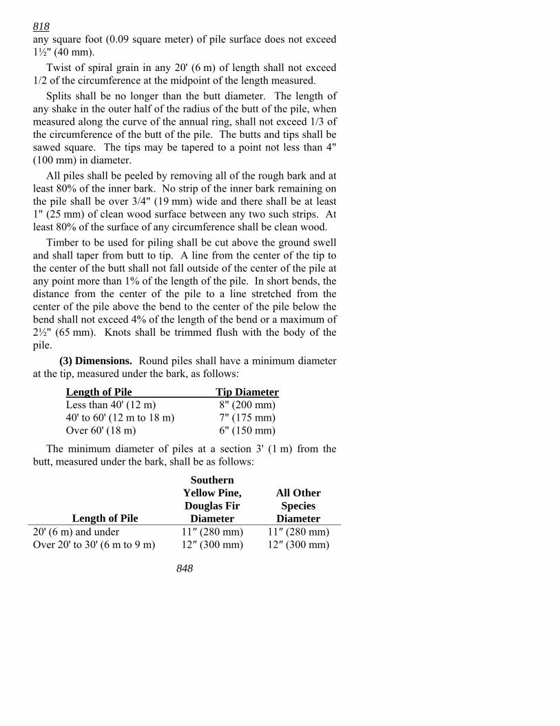
818 any square foot (0.09 square meter) of pile surface does not exceed 1½" (40 mm).
Twist of spiral grain in any 20' (6 m) of length shall not exceed 1/2 of the circumference at the midpoint of the length measured.
Splits shall be no longer than the butt diameter. The length of any shake in the outer half of the radius of the butt of the pile, when measured along the curve of the annual ring, shall not exceed 1/3 of the circumference of the butt of the pile. The butts and tips shall be sawed square. The tips may be tapered to a point not less than 4" (100 mm) in diameter.
All piles shall be peeled by removing all of the rough bark and at least 80% of the inner bark. No strip of the inner bark remaining on the pile shall be over 3/4" (19 mm) wide and there shall be at least 1" (25 mm) of clean wood surface between any two such strips. At least 80% of the surface of any circumference shall be clean wood.
Timber to be used for piling shall be cut above the ground swell and shall taper from butt to tip. A line from the center of the tip to the center of the butt shall not fall outside of the center of the pile at any point more than 1% of the length of the pile. In short bends, the distance from the center of the pile to a line stretched from the center of the pile above the bend to the center of the pile below the bend shall not exceed 4% of the length of the bend or a maximum of 2½" (65 mm). Knots shall be trimmed flush with the body of the pile.
(3) Dimensions. Round piles shall have a minimum diameter at the tip, measured under the bark, as follows:
Length of Pile Tip Diameter Less than 40' (12 m) 8" (200 mm) 40' to 60' (12 m to 18 m) 7" (175 mm) Over 60' (18 m) 6" (150 mm)
The minimum diameter of piles at a section 3' (1 m) from the butt, measured under the bark, shall be as follows:
Length of Pile
Southern Yellow Pine, Douglas Fir
Diameter
All Other Species
Diameter 20' (6 m) and under 11″ (280 mm) 11″ (280 mm) Over 20' to 30' (6 m to 9 m) 12″ (300 mm) 12″ (300 mm)
848
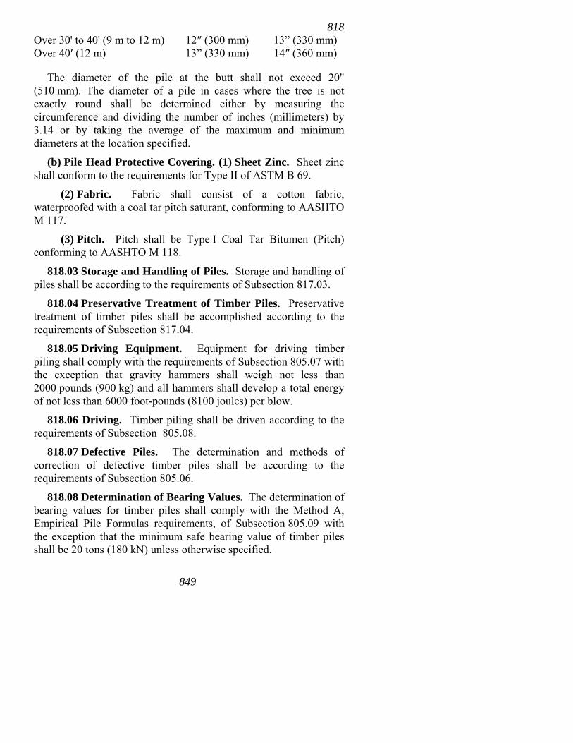
818 Over 30' to 40' (9 m to 12 m) 12″ (300 mm) 13� (330 mm) Over 40′ (12 m) 13� (330 mm) 14″ (360 mm)
The diameter of the pile at the butt shall not exceed 20" (510 mm). The diameter of a pile in cases where the tree is not exactly round shall be determined either by measuring the circumference and dividing the number of inches (millimeters) by 3.14 or by taking the average of the maximum and minimum diameters at the location specified.
(b) Pile Head Protective Covering. (1) Sheet Zinc. Sheet zinc shall conform to the requirements for Type II of ASTM B 69.
(2) Fabric. Fabric shall consist of a cotton fabric, waterproofed with a coal tar pitch saturant, conforming to AASHTO M 117.
(3) Pitch. Pitch shall be Type I Coal Tar Bitumen (Pitch) conforming to AASHTO M 118.
818.03 Storage and Handling of Piles. Storage and handling of piles shall be according to the requirements of Subsection 817.03.
818.04 Preservative Treatment of Timber Piles. Preservative treatment of timber piles shall be accomplished according to the requirements of Subsection 817.04.
818.05 Driving Equipment. Equipment for driving timber piling shall comply with the requirements of Subsection 805.07 with the exception that gravity hammers shall weigh not less than 2000 pounds (900 kg) and all hammers shall develop a total energy of not less than 6000 foot-pounds (8100 joules) per blow.
818.06 Driving. Timber piling shall be driven according to the requirements of Subsection 805.08.
818.07 Defective Piles. The determination and methods of correction of defective timber piles shall be according to the requirements of Subsection 805.06.
818.08 Determination of Bearing Values. The determination of bearing values for timber piles shall comply with the Method A, Empirical Pile Formulas requirements, of Subsection 805.09 with the exception that the minimum safe bearing value of timber piles shall be 20 tons (180 kN) unless otherwise specified.
849
818 818.09 Pile Bents. The piles for any one bent shall be carefully
selected for size to avoid undue bending or distortion of the sway bracing. Care shall be exercised in the distribution of piles of varying sizes to secure uniform strength and rigidity in the bents of any given structure.
818.10 Order Lists for Piling. The Contractor shall furnish piles in compliance with the provisions of Subsection 805.10.
818.11 Cutting Off Timber Piles. Cut-offs shall be accurately made to ensure uniform bearing of the cap on the piles. Cut-offs shall be made at the elevation established by the Engineer. Piles that support timber caps or grillage shall be sawed to conform to the plane of the bottom of the superimposed structure. In general, the length of the pile above the elevation of the cut-off shall be sufficient to permit the complete removal of any material damaged by driving. Piles driven to near the cut-off elevation shall be carefully trimmed of broomed, splintered, or otherwise damaged material.
818.12 Protecting Heads of Treated Timber Piles. Pile heads not encased in concrete, after cutting and prior to placing the caps, shall be treated to prevent decay.
The heads of treated timber piles shall be protected by one of the following coverings:
1) Zinc Covering. The sawed surface shall be covered with 3 applications of a mixture of 60% creosote and 40% roofing pitch or thoroughly brush coated with 3 applications of hot creosote and covered with hot roofing pitch. Before placing the cap, a sheet of 12 gage zinc shall be placed on each pile head. The sheet zinc shall be of sufficient size to project at least 4" (100 mm) outside of the pile. The zinc shall be bent down, neatly trimmed, and securely fastened to the faces of the pile with large headed galvanized roofing nails.
2) Fabric Covering. The heads of piles shall be covered using a Type B membrane waterproofing according to the provisions of Section 815. The cover shall measure at least 6" (150 mm) more in dimension than the diameter of the pile and shall be neatly folded down over the pile and secured by large headed galvanized nails or by binding with not less than 7 complete turns of galvanized wire securely held in place by large headed galvanized nails and staples.
850
818 The edges of the fabric projecting below the wire wrapping shall be neatly trimmed.
3) Approved Coverings. Other coverings that will provide satisfactory protection of the pile head may be used if approved in writing by the Engineer.
818.13 Method of Measurement. Untreated Timber Piling, Treated Timber Piling, and Timber Test Piles will be measured by the actual number of linear feet (meters) of accepted pile remaining in the finished work after all cut-offs or build-ups have been made, based upon lengths shown on the plans or established by the Engineer.
Allowance for pile cut-off, where piles have been furnished or built up according to the length shown on the plans or established by the Engineer, will be made at 50% of the cut-off length.
No allowance for cut-off will be made on piling for any length in excess of the lengths shown on the plans or established by the Engineer.
For piles furnished according to the lengths shown on the plans or established by the Engineer that are found to be too short and are spliced according to an approved detail, an allowance of 4 linear feet (1.2 m) of piling will be made for each timber pile splice in addition to the actual length of accepted pile in place.
No allowance will be made for cut-off or build-up of any portion of a pile that has been damaged, for splices made for the convenience of the Contractor, for extra length ordered for the Contractor's convenience, for cutback necessary for splicing, or for cut-off of 1' (0.3 m) or less necessary to establish uniform bearing of the cap on the piles. Cut-off material shall become the property and responsibility of the Contractor.
818.14 Basis of Payment. Work completed and accepted and measured as provided above will be paid for at the contract unit price bid per linear foot (meter) for Untreated Timber Piling, Treated Timber Piling, or Timber Test Piles, which price shall be full compensation for furnishing material; for transporting; for handling; for driving, jetting, drilling, and excavation; for cut-off, splicing, and build-up; for protection of pile heads; and for all labor, equipment, tools, and incidentals necessary to complete the work.
851
820 Payment will be made under:
Pay Item Pay Unit
Untreated Timber Piling Linear Foot (Meter) Treated Timber Piling Linear Foot (Meter) Timber Test Piles Linear Foot (Meter)
SECTION 819 VACANT
SECTION 820 CLEANING AND PAINTING EXISTING
STRUCTURAL STEEL 820.01 General. This item shall consist of cleaning and painting
existing steel structures and shall include the proper preparation of the surfaces; the application, protection, and drying of the paint coatings; the protection of pedestrians and vehicular or other traffic upon, underneath, or in the vicinity of the structures; the protection against disfigurement by flying sand, rust, and old paint particles; protection from drift, spatters, splashes, and smirches of paint or of paint materials; and protection of the environment.
Structural steel shall be cleaned and painted according to the type specified in the Contract and as outlined in these specifications.
At sites designated in the plans, the Special Protection of the Environment provisions of Subsection 820.04 will be required during cleaning of the existing structural steel. Protection of the environment during painting shall comply with the provisions of Section 638 or Subsection 807.75, as is appropriate for the paint system used.
820.02 Paint System. The paint system shall meet the requirements of Section 638 when Type I cleaning and painting is specified and Subsection 807.75 when Type II cleaning and painting is specified.
820.03 Materials. Paint materials shall meet the requirements of Subsection 638.02 when Type I cleaning and painting is specified
852
820 and Subsection 807.77 when Type II cleaning and painting is specified.
820.04 Special Protection of the Environment. The requirements of this subsection shall apply only for those sites that are so designated in the plans. They cover the requirements for environmental protection, containment, handling, transporting, and disposing of solid wastes generated from bridge paint removal.
(a) Pre-Work Conference. A Pre-Work Conference will be required prior to beginning any paint removal operations. At the Pre-Work Conference, the Contractor shall submit to the Engineer the following information:
• The Contractor's name, address, and phone number. • The designated hazardous waste transporter's name, address,
phone number, owner's name, and US EPA ID Number. • The designated hazardous waste disposal facility name and
site; the Company name, address, and phone number; the name of the facility owner or manager; and the US EPA ID Number.
• The non-hazardous waste disposal facility name and site; the Company name, address, and phone number; the name of the facility owner or manager; and the US EPA ID Number.
The Contractor's operations shall comply with all governing environmental laws and regulations.
(b) Containment Systems. The Contractor shall provide a containment system for capturing all blasting waste during the paint removal operations. The classes of containment required will be either Class 2, 3, or 4, as defined by SSPC Publication 98-04, �Guides on Environmental Protection�. The class of containment required for each individual site will be determined by the Department and designated on the plans.
The containment system shall: • Prevent emissions of dust and debris that could pollute the
ambient air, water, or soil. • Be designed with consideration given to the proximity of the
containment to other structures (e.g., houses, businesses, etc.) and to areas of public access (e.g., sidewalks, bike paths, etc.).
• Be capable of withstanding heavy winds and weather conditions that can be expected at project sites.
853
820 • Provide ventilation to minimize the health risks and provide
adequate visibility to personnel working inside. • Not prevent the flow of traffic either on or below the bridge
unless provisions have been made in the plans for traffic detours.
If the Engineer determines that the containment system fails to comply with these requirements, cleaning and painting operations shall cease immediately and shall not resume until corrections to the containment system have been made. If the Contractor's operations result in contamination, the situation shall be remedied at no cost to the Department before operations are resumed. In addition, any and all fines and penalties assessed against and costs incurred by the Department will be assessed to the Contractor. The Department will not be responsible for any time delay due to the Contractor's failure to comply with these requirements.
The Contractor shall protect all storm and sanitary sewer systems from water borne solid waste contamination generated by cleaning operations.
(c) Handling and Transporting Non-Hazardous and Hazardous Waste. The Contractor shall handle, store, and transport both hazardous and non-hazardous solid waste according to the requirements of 40 CFR §§ 261, 262, 263, and 265; 49 CFR §§ 172 and 177; and HM-181. The solid waste will be determined hazardous or non-hazardous according to Appendix II of 40 CFR § 268.3G by an accredited laboratory selected by the Department using Toxicity Characteristic Leaching Procedures (TCLP). Sampling and testing will be the responsibility of the Department.
The Engineer will notify the Contractor in writing of the TCLP results.
The Contractor shall be responsible for the proper storage of the solid waste at or near the bridge site until such time that it is transported to the treatment or disposal facility. Solid waste shall be secured from vandalism, theft, spillage, and damage by adjacent traffic. Solid waste shall not be stored in a flood plain. All appropriate authorizations, manifests, and certifications are to be correctly completed and signed prior to removal to the permitted landfill or hazardous waste facility.
854
820 The solid waste will be treated and disposed of according to the
requirements of 40 CFR §§ 148, 264, 265, 268, and 302.
The waste shall be stored in sealable steel drums (approx. 55 gallon [200-liter] volume) or other U.S. Department of Transportation (DOT) approved containers. The containers shall be clearly marked with DOT approved labels clearly stating the Bridge Number, location, and number of containers from that site (e.g., 1 of 4, 2 of 4, 3 of 4, etc.). Information shall be provided on these labels according to 40 CFR § 262, 49 CFR § 172, 49 CFR § 177, and HM-181.
(1) Non-Hazardous Waste. If the TCLP tests show the solid waste to be non-hazardous, the Contractor shall dispose of the waste at the non-hazardous waste facility so designated at the pre-work conference.
The Department will provide the Non-Hazardous Waste Certification. The Certification shall be signed by the Testing Laboratory Representative, the Department's Environmental Division Representative, the Engineer, and the Contractor prior to removal of the waste from the storage site. Upon delivery to the non-hazardous waste disposal site, the Certification shall be signed by a responsible representative of that facility. The Certification shall be returned to and become the property of the Department.
(2) Hazardous Waste. If the TCLP tests show the waste to be hazardous, the Contractor shall dispose of the hazardous waste according to the following requirements:
The containers shall be clearly marked with DOT approved hazardous waste labels. Information shall be provided on these labels according to 40 CFR § 262 and 49 CFR § 172.
All hazardous solid waste shall be accompanied by an Arkansas Department of Environmental Quality (ADEQ) Manifest or an approved Hazardous Waste Manifest supplied by the Contractor's Treatment, Storage and Disposal (TSD) facility. Actions should follow 40 CFR § 268.7 "Land Ban Disposal Procedures".
The transporter shall also hold valid permits from all states in which the waste will travel between the storage site and the final hazardous waste disposal facility.
855
820 The properly executed original copy of the hazardous waste
manifest shall be returned to and will become the property of the Department. All other copies of the manifest shall be distributed as designated on the manifest.
820.05 Cleaning and Painting of Surfaces. (a) General. Structural steel surfaces shall receive either Type I or Type II cleaning and painting as specified in the Contract.
(b) Type I Cleaning and Painting. (1) Cleaning. Cleaning shall consist of commercial blast cleaning all rusty areas of structural steel and brush-off blast cleaning of the remaining steel.
Steel surfaces shall be cleaned as follows:
a. Rusty and Deteriorated Steel Surfaces. All rust shall be removed down to bare metal and the surface given a blast cleaning conforming to Steel Structures Painting Council Surface Preparation No. 6 (SSPC-SP 6) Commercial Blast Cleaning. The work shall include the removal of all rust that adheres to the steel surfaces after blast cleaning and that must be loosened by striking with a hammer or lifting with a putty knife.
b. Non-adherent Paint. All paint not adhering to existing steel surfaces shall be removed to bare metal and the steel surface given a blast cleaning conforming to SSPC-SP 6, Commercial Blast Cleaning. However, if upon removal of the top layer of non-adhering paint, a sound layer of paint adhering to the steel surface is exposed, that painted surface may be retained and cleaned as described in c. below.
c. Existing Sound Paint. All paint found to be sound, with satisfactory bond to the existing steel surface, shall be blast cleaned to produce a surface conforming to SSPC-SP 7, Brush-off Blast Cleaning. Paint to be retained shall be blasted to a feather edge tapering back 3" (75 mm) into the existing sound paint to provide a smooth uniform surface.
856
820 (2) Painting. All steel surfaces shall be painted with an
aluminum epoxy paint system as specified in Section 638 unless otherwise specified in the proposal and/or on the plans.
(c) Type II Cleaning and Painting. (1) Cleaning. Cleaning will consist of cleaning all structural steel surfaces to produce a surface conforming to SSPC-SP 10, Near-White Blast Cleaning.
(2) Painting. All steel surfaces shall be painted with a paint system as specified in Subsection 807.75 unless otherwise specified in the proposal and/or on the plans.
820.06 Previously Cleaned and Painted Surfaces. (a) Previously Cleaned Surfaces. All steel surfaces that have been previously cleaned but left exposed allowing rust to form shall be re-cleaned and all rust removed prior to application of paint.
(b) Previously Painted Surfaces. All surfaces to be painted shall be clean and free of dust or other objectionable matter. Application of paint to the previously painted surface shall be within the time frame as recommended by the manufacturer. If this length of time is exceeded between the application of the various coats, the weathered surface of the preceding coat shall be cleaned or removed as required to assure good bonding.
820.07 Cleaning the Bridge Roadway Surface. The Contractor shall sweep clean the bridge roadway surface of each span prior to starting painting operations on that span and keep the bridge roadway surface clean until all work of painting has been completed and accepted for each individual span.
820.08 Traffic Control. Prior to beginning work, the Contractor shall submit a traffic control plan to the Engineer for approval. Unless otherwise specified, the bridge and the roadway beneath the bridge shall be kept open to traffic at all times when paint is not being applied to the structure. Except as noted below, the Contractor may, with the approval of the Engineer, close the bridge or roadway to traffic for periods not to exceed 10 minutes. Following each closed period, the bridge or roadway shall be opened until traffic clears. The Contractor shall exert every effort to hold inconvenience to the traveling public to a minimum and shall make use of such flagging personnel, signs, and barricades as the Engineer may direct in the interest of safety and convenience. The
857
820 use of barricades and warning signs shall be governed by Sections 603 and 604 and the MUTCD.
When cleaning or painting structures over a multi-lane highway, a minimum of one lane of traffic in each direction shall be left open
All scaffolding, ladders, and other equipment, materials, or tools that restrict vertical or horizontal clearances shall be clear of all travel ways and shoulders when not in use or protected by appropriate traffic control devices.
820.09 Method of Measurement. (a) Cleaning and Painting Existing Structural Steel will be measured by the ton (metric ton) of structural steel. Quantities of structural steel shown on the plans will be final. When both types of cleaning and painting existing structural steel are included in the Contract, the quantities of each type may vary depending upon field conditions and as determined by the Engineer.
(b) Disposal of all material classified as hazardous waste will be measured by the lump sum for each site and shall include the complete and proper disposal of all material from that site classified as hazardous waste.
Work required for containment, collection, and temporary storage of all waste material and for the disposal of all non-hazardous waste will not be measured or paid for separately but will be considered included in the contract unit price bid for Cleaning and Painting Existing Structural Steel.
820.10 Basis of Payment. (a) Cleaning and Painting. Work completed and accepted and measured as provided above will be paid for at the contract unit price bid per ton (metric ton) for Cleaning and Painting Existing Structural Steel, Type I or Type II, which price shall be full compensation for cleaning the metal surfaces; for painting the structure; and for furnishing materials and all labor, equipment, tools, and incidentals necessary to complete the work.
(b) Hazardous Waste. Work completed and accepted and measured as provided above will be paid for at the contract lump sum price bid for Disposal of Hazardous Waste (Site No.__) for each site, which price shall be full compensation for the complete and proper disposal of all hazardous waste generated at that site, including transporting the waste to the designated disposal site, and 858
821 for furnishing materials and all labor, equipment, tools, and incidentals necessary to complete the work.
Payment will be made under:
Pay Item Pay Unit
Cleaning and Painting Existing Structural Steel (Type ___) Ton (Metric Ton)
Disposal of Hazardous Waste (Site No. ___) Lump Sum
SECTION 821 MODIFICATION OF EXISTING BRIDGE
STRUCTURES 821.01 Description. This item shall consist of removal and
modification of portions of existing bridge substructures and/or superstructures to accommodate the remodeling of the structures according to the plans and specifications.
821.02 Construction Requirements. The existing portions of the structure shall be removed to the lines and elevations shown on the plans or established by the Engineer.
When components of an existing bridge structure are to be retained and joined to the proposed work, their measurements and horizontal and vertical relationships to the proposed work shall be verified by the Contractor. The results of the verification process shall be submitted in writing to the Engineer and Bridge Engineer before the new construction is started. If the verification process reveals that adjustments are required, recommendations for such adjustments shall be included in the submittal for approval.
The Contractor shall verify the span lengths and skew angles and report the results to the Engineer and the Bridge Engineer before shop drawings are approved.
The Contractor shall conduct removal operations in a manner that will not damage the portions of the structure to remain. Any damage caused by the Contractor shall be repaired or the damaged portion of the structure replaced at no cost to the Department.
859
821 Any inspection or engineering costs associated with the repair or
replacement of the damaged portion of the structure will be assessed against the Contractor.
When removing a portion of the structure for widening, particular care shall be used in removing the deck slab and curbs so as to secure straight line cuts and vertical faces. A 1" (25 mm) deep slot shall be sawed in the top of the slab and 1" (25 mm) round holes, extending from the top of the slab to within 2" (50 mm) of the bottom side, shall be drilled at 8" (200 mm) centers along the cut line. In addition, a plane of weakness approximately 1" (25 mm) deep shall be sawed or cut with chisels at the cut line on the underside of the slab. The use of explosives in removing concrete will not be permitted.
Transverse slab bars that will extend into the new slab shall be cleaned of all concrete and laitance. Bars extending from the existing concrete shall not be cut but shall extend into the new concrete unless otherwise specified. Existing concrete surfaces shall be cleaned and wetted before placing new concrete against them.
Any dowel bars required shall be installed according to the plan details. Reinforcing steel that is to be doweled into existing concrete shall be installed into drilled holes and secured using an approved non-shrink grout or a polyester/epoxy resin system listed on the QPL. The diameter of the drilled holes and the installation procedures shall be as recommended by the grout/epoxy resin system manufacturer.
Disposition of the material removed shall be according to Section 205.
821.03 Method of Measurement. Modification of Existing Bridge Structures will be measured on the lump sum basis for each bridge.
Work involved in remodeling bridge structures will be measured and paid for according to the applicable specifications for the particular items.
821.04 Basis of Payment. Work completed and accepted and measured as provided above will be paid for at the contract lump sum price bid for Modification of Existing Bridge Structure, which price shall be full compensation for removal of the portions of the structure designated; for disposing of the material removed; for any 860
822 necessary bending of existing bars; for furnishing and installing dowel bars; and for all materials, labor, equipment, tools, and incidentals necessary to complete the work.
Payment will be made under:
Pay Item Pay Unit
Modification of Existing Bridge Structure (Bridge No.___) Lump Sum
SECTION 822 REPAIR AND OVERLAY OF CONCRETE BRIDGE
DECKS 822.01 Description. This item shall consist of repair and overlay
of concrete bridge decks as designated on the plans or as specified by the Engineer.
Bridge deck repair and bridge deck overlay shall be classified as follows:
(a) Bridge Deck Repair. (1) Bridge Deck Repair Without Subsequent Overlay. This item shall consist of removing unsound portions of the existing bridge deck concrete, disposing of the removed concrete, and replacing the removed volume with concrete meeting the requirements of Section 802 for Class S(AE) Concrete or Subsection 822.02. The concrete shall have a surface finish equivalent to that of the existing deck surface.
(2) Bridge Deck Repair With Subsequent Overlay. This item shall consist of removing unsound portions of the existing bridge deck concrete, disposing of the removed concrete, and replacing the removed volume with concrete meeting the requirements of Subsection 822.02 at the same time the bridge deck overlay is placed.
(b) Bridge Deck Overlay. This item shall consist of removing the existing deck concrete to a depth 1/2" (12 mm) below the existing finished surface, except as otherwise noted on the plans, disposing of the removed concrete, and overlaying with concrete meeting the requirements of Subsection 822.02. The thickness of the concrete overlay shall be measured from the elevation established for removal of the existing deck to the final surface elevation as shown on the plans or established by the Engineer. 861
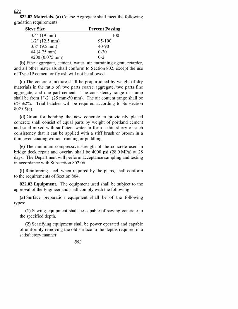
822 822.02 Materials. (a) Coarse Aggregate shall meet the following
gradation requirements: Sieve Size Percent Passing 3/4" (19 mm) 100 1/2" (12.5 mm) 95-100 3/8" (9.5 mm) 40-90 #4 (4.75 mm) 0-30 #200 (0.075 mm) 0-2 (b) Fine aggregate, cement, water, air entraining agent, retarder,
and all other materials shall conform to Section 802, except the use of Type IP cement or fly ash will not be allowed.
(c) The concrete mixture shall be proportioned by weight of dry materials in the ratio of: two parts coarse aggregate, two parts fine aggregate, and one part cement. The consistency range in slump shall be from 1"-2" (25 mm-50 mm). The air content range shall be 6% ±2%. Trial batches will be required according to Subsection 802.05(c).
(d) Grout for bonding the new concrete to previously placed concrete shall consist of equal parts by weight of portland cement and sand mixed with sufficient water to form a thin slurry of such consistency that it can be applied with a stiff brush or broom in a thin, even coating without running or puddling.
(e) The minimum compressive strength of the concrete used in bridge deck repair and overlay shall be 4000 psi (28.0 MPa) at 28 days. The Department will perform acceptance sampling and testing in accordance with Subsection 802.06.
(f) Reinforcing steel, when required by the plans, shall conform to the requirements of Section 804.
822.03 Equipment. The equipment used shall be subject to the approval of the Engineer and shall comply with the following:
(a) Surface preparation equipment shall be of the following types:
(1) Sawing equipment shall be capable of sawing concrete to the specified depth.
(2) Scarifying equipment shall be power operated and capable of uniformly removing the old surface to the depths required in a satisfactory manner.
862
822 (3) Sand blasting or other surface cleaning equipment shall be
capable of removing rust and old concrete from the exposed reinforcement and concrete laitance from the existing concrete surface.
(4) Power driven hand tools for removal of concrete will be permitted. However, jackhammers heavier than nominal 30 pound (14 kg) class and chipping hammers heavier than nominal 15 pound (7 kg) class shall not be used. Jackhammers or mechanical chipping tools shall generally not be operated at an angle in excess of 45° measured from the surface of the deck.
(b) Placing and finishing equipment shall include a mechanical screed meeting the requirements of Subsection 802.20, equipped with sufficient vibrators, and having an effective weight to sufficiently consolidate the mixture.
The finishing machine shall be capable of forward and reverse motion under positive control. Provision shall be made for raising the screed to clear the screeded surface for traveling in reverse.
Supporting rails upon which the finishing machine travels will be required on all overlay work. The support for these rails shall be fully adjustable (not shimmed) to obtain the specified concrete profile.
When placing concrete that abuts a previously completed surface, that side of the screed that abuts the completed surface shall match the grade of the completed surface. It will not be permissible to drill holes in the completed surface for the purpose of supporting a rail.
For bridge deck repair without subsequent overlay, the Contractor may utilize hand methods of placing and finishing concrete that produces satisfactory results.
822.04 Preparation of Surface. (a) General. Concrete shall be removed from areas designated on the plans or by the Engineer to the depth specified consistent with the classification for that area.
The use of hand tools may be required to remove final particles of concrete to achieve the required depth.
Immediately before applying grout in preparation for placement of new concrete, the concrete and reinforcing steel surfaces shall be sand blasted, followed by an air or water cleaning. The sand blasting shall be of such extent as to remove all dust, dirt, oil, and 863
822 other foreign material, as well as any unsound concrete or laitance, from the surface and edges against which the overlay is to be placed.
(b) Bridge Deck Repair. Concrete shall be removed by chipping or by a combination of scarifying and chipping, except that final cleanup may require the use of hand tools. Removal for bridge deck repair without subsequent overlay shall extend to at least 3/4" (19 mm) below the bottom of the top reinforcing bars. Removal for bridge deck repair with subsequent overlay shall extend to at least the top of the top reinforcing bars. In either case, the depth removed shall extend deeper, if necessary, to remove unsound concrete. This removal may be accomplished coincidental with preparation for an overlay.
Where bond between existing concrete and reinforcing steel has been destroyed, the concrete adjacent to the bar shall be removed to a depth that will permit new concrete to bond to the entire periphery of the bar so exposed. A minimum of 3/4" (19 mm) clearance shall be required around the bar. Care shall be exercised to prevent cutting or damaging any exposed reinforcing steel.
The Engineer may require enlarging a designated portion of the deck should inspection indicate deterioration of the concrete or corrosion of the reinforcing steel beyond the limits previously designated.
(c) Bridge Deck Overlay. The entire existing concrete deck area shall be uniformly scarified and prepared to a depth as specified in Subsection 822.01.
The minimum thickness of concrete above the prepared surface or reinforcing steel shall be 1¾" (45 mm), but shall be greater when specified on the plans or by the Engineer.
The clearance of the screed over the prepared deck surface shall be checked as follows before concrete is placed: A filler block having a thickness 1/8" (3 mm) less than the overlay thickness shall be attached to the bottom of the screed, and with screed guides in place, the screed shall be passed over the area to be overlayed. As an alternate to passage of the finishing machine, an approved template, supported by the screed guides, may be passed over the overlay area. Where the intended clearance does not permit use of this method, a stringline or other means shall be used, subject to approval of the Engineer.
864
822 All old concrete that does not have sufficient clearance shall be
removed. All reinforcing steel that does not have sufficient clearance shall be depressed and fastened down. It may be necessary to remove concrete beneath some reinforcement to permit depressing the reinforcement adequately. The minimum clear distance around these bars for placement of new concrete shall be 3/4" (19 mm). Any damaged epoxy coating of existing reinforcing steel shall be repaired according to Subsection 804.05.
822.05 Placing and Finishing Concrete. After the surface has been cleaned, and immediately before placing concrete, a thin coating of bonding grout shall be scrubbed into the dry, prepared surface. Care shall be exercised to ensure that all areas receive a thorough, even coating and that the grout does not become dry before it is covered with concrete.
Concrete shall be placed in a continuous operation.
The overlay shall be consolidated to 98% of maximum theoretical density as determined by AASHTO T 121. All overlay concrete within 12" (0.3 m) of any edge of a placement shall be spaded, hand vibrated, or troweled, as required, to assure that density of the mix at the edge is obtained. The Engineer may require that sections of the overlay along the edge be removed in order to confirm proper consolidation and bonding of the overlay. The removal shall be accomplished by sawing and chipping or by coring. The removal and replacement of the overlay or any part of the existing deck to make this confirmation will be at no cost to the Department.
To assure a neat junction, concrete in an overlay previously placed shall be sawed to a straight and vertical edge at longitudinal and transverse joints before the subsequent concrete is placed.
Joints between new overlay placements shall be sawed to provide a straight and vertical 1/4" x 1" (6 mm x 25 mm) joint. Joints adjacent to existing concrete, for both repair and overlay, may be 1/4" x 1" (6 mm x 25 mm) formed joints, or they may be sawed, provided a straight and vertical joint is obtained. These joints shall be prepared according to Subsection 501.05 and filled with Type 3 or 4 silicone sealer meeting the requirements of Subsection 501.02, unless otherwise noted on the plans.
865

822 Although repair is considered to begin 1/2" (12 mm) below the
original concrete surface, repair concrete shall be placed monolithically with the concrete overlay.
The final finish of the overlay shall be a Class 5, Tined Bridge Roadway Surface Finish according to Subsection 802.19 unless otherwise noted on the plans.
For bridge deck repair without subsequent overlay, the above procedures for application of grout and placement and consolidation of concrete shall be followed, and the surface shall be finished to a surface finish equivalent to that of the existing deck surface.
822.06 Curing Concrete. Curing of the concrete shall be according to Subsection 802.17 except as modified by the following: A clear membrane curing compound shall be applied to the exposed concrete immediately after finishing. The overlay or repair shall be kept continuously wet and cured for at least 72 hours. In periods of cool weather the Engineer will extend this curing period as necessary to obtain 72 hours above 55° F (13° C).
822.07 Limitation of Operations. No concrete repair or overlay shall be placed when the air or deck temperature is below 40° F (4° C). The temperature of the concrete at the time of placement shall not exceed 85° F (29° C).
No preparation, placing, or finishing equipment will be operated on a previously placed concrete repair or overlay for at least 36 hours after placement.
Preparation for a repair or overlay may be started adjacent to a previously placed repair or overlay the day following its placement. If this preparation is started before the end of the normal 72 hour curing period, the work will be restricted as follows:
1) Sawing or other operations shall interfere with the curing process for the minimum practical time, and only in the immediate work area. The curing shall be resumed promptly.
2) No power driven tools heavier than a 15 pound (7 kg) chipping hammer shall be used.
3) Air compressors shall only be operated on the deck directly over the piers.
866
822 4) No loads other than necessary construction equipment will
be permitted on any portion of the bridge deck that has undergone preparation prior to placement of the concrete.
5) No vehicles will be permitted on the finished concrete for 72 hours after placement and curing is complete.
822.08 Quality Control and Acceptance. Quality control and acceptance testing shall be according to the provisions of Subsection 802.06. In addition, the consolidation of the concrete shall be determined by AASHTO T 271. The Department will perform acceptance sampling and testing in accordance with Subsection 802.06.
822.09 Method of Measurement. Bridge Deck Repair or Bridge Deck Overlay will be measured by the square yard (square meter) for the areas actually repaired or overlayed.
When Bridge Deck Repair is accomplished in conjunction with Bridge Deck Overlay, the respective items will be measured separately for the areas actually repaired and overlayed.
Reinforcing steel required by the plans in bridge deck repair and overlay will be measured and paid for according to Section 804.
If the Contractor's methods cause damage to existing sound concrete or to reinforcing steel that is designated to be retained, such damaged material shall be repaired or replaced by the Contractor at no cost to the Department.
822.10 Basis of Payment. Work completed and accepted and measured as provided above will be paid for at the contract unit price bid per square yard (square meter) for Bridge Deck Repair or Bridge Deck Overlay, which price shall be full compensation for removal and disposal of concrete; for preparation of the area to be repaired or overlayed; for furnishing, placing, consolidating, finishing, and curing concrete; and for all materials, forms, labor, equipment, tools, and incidentals necessary to complete the work.
Payment will be made under:
Pay Item Pay Unit
Bridge Deck Repair Square Yard (Square Meter) Bridge Deck Overlay Square Yard (Square Meter)
867

868

822
869
This page intentionally blank.