Embed Size (px)
Citation preview
844 Compact Slide Gate Operator: Installation Manual
Contents
Important Safety Information........................................................................2 844 Technical Data .......................................................................................4 Unpacking the Operator ................................................................................5 The 844 Compact Slide Gate Operator .........................................................6
General Characteristics .............................................................................6 Operating Logic ........................................................................................6
B Mode..................................................................................................6 C Mode..................................................................................................6 BC Mode ...............................................................................................6 CB Mode ...............................................................................................6 E1 (Semi-Automatic) Mode ..................................................................6 A1 (Automatic) Mode ...........................................................................7 S1 (Security) Mode ...............................................................................7 S2 (Security Plus) Mode .......................................................................7 Manual Release Mechanism..................................................................7
Installation Instructions.................................................................................9 Setting the Concrete Forms.......................................................................9 Mounting the Operator............................................................................10
Chain Operator ....................................................................................10 Rack and Pinion Operator ...................................................................10
Connecting the Control Panel to Power and an Activating Device ........12 Setting Up the Limit Switches ...............................................................13 Checking the Motor’s Direction of Rotation...........................................17 Adjusting the Braking .............................................................................17 Connecting Other Accessories ................................................................17 Adjusting the Clutch Torque..................................................................17 Setting the DIP Switches.........................................................................18
The 844 B/C Control Panel .................................................................18 The 844 MPS Control Panel ...............................................................18
Finishing the Installation.........................................................................18 Maintenance ................................................................................................19 Troubleshooting ..........................................................................................20 Exploded View, 844....................................................................................23 FAAC International, Inc. 303 Lexington Avenue Cheyenne, WY 82007 www.faacusa.com
2
Important Safety InformationBoth the installer and the owner and/or operator of this system need to read and understand this installation manual and the safety instructions supplied with other components of the gate system. This information should be retained by the owner and/or operator of the gate.
WARNING! To reduce the risk of injury or death
1. READ AND FOLLOW ALL INSTRUCTIONS.
2. Never let children operate or play with gate controls. Keep the remote control away from children.
3. Always keep people and objects away from the gate. NO ONE SHOULD CROSS THE PATH OF THE MOVING GATE.
4. Test the gate operator monthly. The gate MUST reverse on contact with a rigid object or stop when an object activates the non-contact sensors. After adjusting the force or the limit of travel, retest the gate operator. Failure to adjust and retest the gate operator properly can increase the risk of injury or death.
5. Use the emergency release only when the gate is not moving.
6. KEEP GATES PROPERLY MAINTAINED. Read the owner’s manual. Have a qualified service person make repairs to gate hardware.
7. The entrance is for vehicles only. Pedestrians must use separate entrance.
8. SAVE THESE INSTRUCTIONS.
There are three kinds of safety issues involved with an automatic gate operator: issues arising from the design of the gate, from the installation of the gate and the operator, and from the use of the gate operator. The following information is designed to help you be sure your gate and its operator are well-designed, installed
correctly, and used safely.
Gate Design 1. A gate is a potential traffic hazard, so it is im-
portant that you locate the gate far enough away from the road to eliminate the potential of traffic getting backed up. This distance is affected by the size of the gate, how often it is used, and how fast the gate operates.
2. The operator you choose to install on your gate must be designed for the type and size of your gate and for the frequency with which you use the operator.
3. Your gate must be properly installed and must work freely in both directions before the automatic operator is installed.
4. An automatic operator should be installed on the inside of the property/fence line. Do not install the operator on the public side of the property/fence line.
5. Pedestrians should not use a vehicular gate system. Prevent such inappropriate use by installing separate gates for pedestrians.
6. Exposed, reachable pinch points on a gate are potentially hazardous and must be eliminated or guarded.
7. Outward swinging gates with automatic operators should not open into a public area.
8. The operating controls for an automatic gate must be secured to prevent the unauthorized use of those controls.
9. The controls for an automatic gate should be located far enough from the gate so that a user cannot accidentally touch the gate when operating the controls.
10. An automatic gate operator should not be installed on a gate if people can reach or extend their arms or legs through the gate. Such gates should be guarded or screened to prevent such access.
Installation 1. If you have any question about the safety of the
gate operating system, do not install this operator. Consult the operator manufacturer.
2. The condition of the gate structure itself directly affects the reliability and safety of the gate operator.
3. Only qualified personnel should install this
3
equipment. Failure to meet this requirement could cause severe injury and/or death, for which the manufacturer cannot be held responsible.
4. The installer must provide a main power switch that meets all applicable safety regulations.
5. Clearly indicate on the gate with a minimum of 2 warning signs (visible from either side of the gate) that indicate the following:
• The gate is automatic and could move at any time, posing a serious risk of entrapment.
• Children should not be allowed to operate the gate or play in the gate area.
• The gate should be operated only when it is visible to the operator and the when the area is free of people and obstructions.
6. It is extremely unsafe to compensate for a damaged gate by overtightening a clutch or increasing hydraulic pressure.
7. Devices such as reversing edges and photocells must be installed to provide better protection for personal property and pedestrians. Install reversing devices that are appropriate to the gate design and gate application.
8. Before applying electrical power, be sure that the voltage requirements of the equipment correspond to your supply voltage. Refer to the label on your operator system.
Use 1. Use this equipment only in the capacity for which it
was designed. Any use other than that stated should be considered improper and therefore dangerous.
2. When using any electrical equipment, observe some fundamental rules:
• Do not touch the equipment with damp or humid hands or feet.
• Do not install or operate the equipment with bare feet.
• Do not allow small children or incapable persons to use the equipment.
3. If a gate system component malfunctions, turn off the main power before making any attempt to repair it.
4. Do not attempt to impede the movement of the gate. You may injure yourself as a result.
5. This equipment may reach high temperatures during operation; therefore, use caution when touching the external housing of the operator.
6. Learn to use the manual release mechanism according to the procedures found in this in-stallation manual.
7. Before carrying out any cleaning or maintenance operations, disconnect the equipment from the electrical supply.
8. To guarantee the efficiency of this equipment, the manufacturer recommends that qualified personnel periodically check and maintain the equipment.
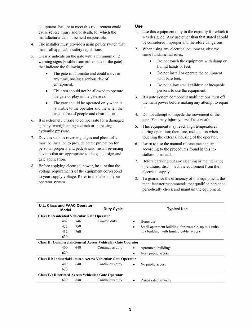
U.L. Class and FAAC Operator
Model Duty Cycle Typical Use
Class I: Residential Vehicular Gate Operator 402 746 422 750 412 760 630
Limited duty • Home use • Small apartment building, for example, up to 4 units
in a building, with limited public access
Class II: Commercial/General Access Vehicular Gate Operator 400 640 620
Continuous duty • Apartment buildings • Very public access
Class III: Industrial/Limited Access Vehicular Gate Operator 400 640 620
Continuous duty • No public access
Class IV: Restricted Access Vehicular Gate Operator 620 640 Continuous duty • Prison rated security
4
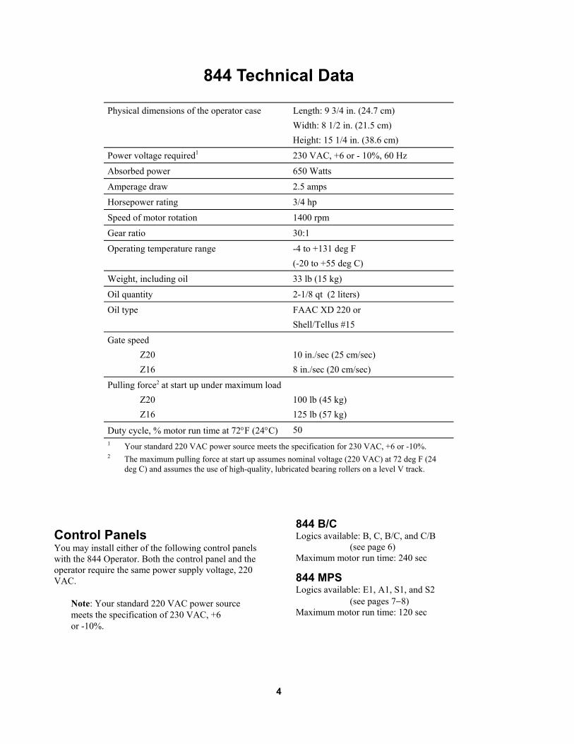
844 Technical Data
Physical dimensions of the operator case Length: 9 3/4 in. (24.7 cm) Width: 8 1/2 in. (21.5 cm) Height: 15 1/4 in. (38.6 cm)
Power voltage required1 230 VAC, +6 or - 10%, 60 Hz
Absorbed power 650 Watts
Amperage draw 2.5 amps
Horsepower rating 3/4 hp
Speed of motor rotation 1400 rpm
Gear ratio 30:1
Operating temperature range -4 to +131 deg F (-20 to +55 deg C)
Weight, including oil 33 lb (15 kg)
Oil quantity 2-1/8 qt (2 liters)
Oil type FAAC XD 220 or Shell/Tellus #15
Gate speed Z20 Z16
10 in./sec (25 cm/sec) 8 in./sec (20 cm/sec)
Pulling force2 at start up under maximum load Z20 Z16
100 lb (45 kg) 125 lb (57 kg)
Duty cycle, % motor run time at 72°F (24°C) 50 1 Your standard 220 VAC power source meets the specification for 230 VAC, +6 or -10%. 2 The maximum pulling force at start up assumes nominal voltage (220 VAC) at 72 deg F (24
deg C) and assumes the use of high-quality, lubricated bearing rollers on a level V track.
Control Panels You may install either of the following control panels with the 844 Operator. Both the control panel and the operator require the same power supply voltage, 220 VAC.
Note: Your standard 220 VAC power source meets the specification of 230 VAC, +6 or -10%.
844 B/C Logics available: B, C, B/C, and C/B (see page 6) Maximum motor run time: 240 sec
844 MPS Logics available: E1, A1, S1, and S2 (see pages 7−8) Maximum motor run time: 120 sec
5
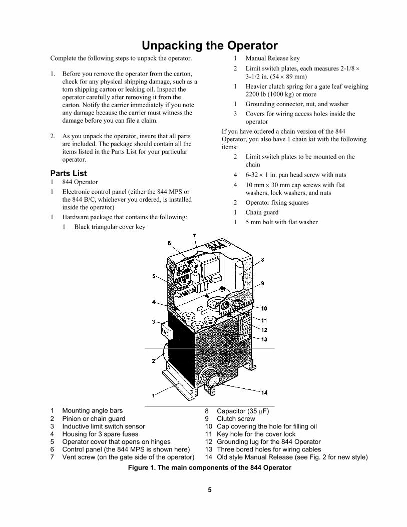
Unpacking the Operator Complete the following steps to unpack the operator. 1. Before you remove the operator from the carton,
check for any physical shipping damage, such as a torn shipping carton or leaking oil. Inspect the operator carefully after removing it from the carton. Notify the carrier immediately if you note any damage because the carrier must witness the damage before you can file a claim.
2. As you unpack the operator, insure that all parts
are included. The package should contain all the items listed in the Parts List for your particular operator.
Parts List 1 844 Operator 1 Electronic control panel (either the 844 MPS or
the 844 B/C, whichever you ordered, is installed inside the operator)
1 Hardware package that contains the following: 1 Black triangular cover key
1 Manual Release key 2 Limit switch plates, each measures 2-1/8 ×
3-1/2 in. (54 × 89 mm) 1 Heavier clutch spring for a gate leaf weighing
2200 lb (1000 kg) or more 1 Grounding connector, nut, and washer 3 Covers for wiring access holes inside the
operator If you have ordered a chain version of the 844 Operator, you also have 1 chain kit with the following items:
2 Limit switch plates to be mounted on the chain
4 6-32 × 1 in. pan head screw with nuts 4 10 mm × 30 mm cap screws with flat
washers, lock washers, and nuts 2 Operator fixing squares 1 Chain guard 1 5 mm bolt with flat washer
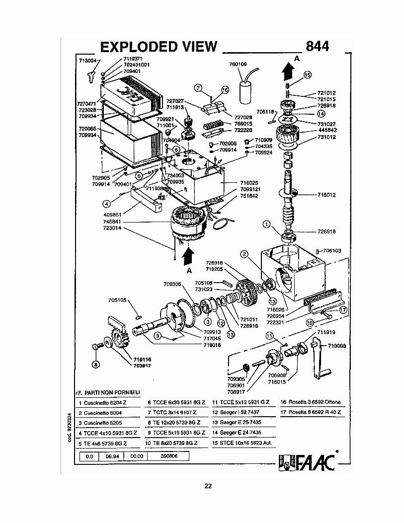
1 Mounting angle bars 8 Capacitor (35 µF) 2 Pinion or chain guard 9 Clutch screw 3 Inductive limit switch sensor 10 Cap covering the hole for filling oil 4 Housing for 3 spare fuses 11 Key hole for the cover lock 5 Operator cover that opens on hinges 12 Grounding lug for the 844 Operator 6 Control panel (the 844 MPS is shown here) 13 Three bored holes for wiring cables 7 Vent screw (on the gate side of the operator) 14 Old style Manual Release (see Fig. 2 for new style)
Figure 1. The main components of the 844 Operator
6
The 844 Compact Slide Gate Operator General Characteristics The FAAC 844 Compact Slide Gate Operator is available in a rack and pinion or a chain model. The operator comes as a package containing the drive unit and electronic control panel. All external reversing devices and other accessories must be ordered separately. The electronic control panel installed in the cover of the 844 Operator is a microprocessor-based controller that accepts a full range of product accessories and reversing devices to allow the maximum flexibility in designing the gate system. The advanced design of the operator features a small, self-contained unit composed of an electric motor with a built-in clutch and a reduction gear box, both housed in a die-cast aluminum casing. The motor drives the rack or chain to slide the gate. An adjustable friction clutch is located on the input side of the gear box so that when torque exceeds a preset value, the drive torque on the output shaft remains at a constant level. The holding power of the gear mechanism ensures that the gate stays perfectly shut. There is no need to fit an additional lock on the gate. The electric motor, two-disc clutch, and reduction gear are completely immersed in oil that lubricates the moving parts and also dissipates heat generated during operation. The heat is dissipated through the outer casing of black anodized aluminum. The Manual Release mechanism, a key- and lever-operated device, allows you to open or close the gate by hand whenever the need arises. The Manual Release mechanism is useful, for example, when the electrical power goes out and you want to open or close the gate. A limit switch assembly stops the drive motor when the limit switch plates mounted on the rack or chain are sensed. The limit switch is inductive and watertight to increase its reliability and functionality. The adjustable electronic braking system insures that the gate stops exactly where and when required. Two die-cast flanges surround the pinion to prevent foreign objects from being inserted between the rack and pinion either accidentally or intentionally. A guard around the sprockets on the chain version of the 844 Operator functions similarly.
Operating Logic The 844 Operator functions with either the 844 B/C control panel or the 844 MPS control panel. The two panels provide two different sets of operating logics:
• 844 B/C: B, C, B/C, and C/B • 844 MPS: E1, A1, S1, and S2
The paragraphs below explain the various logic modes. The tables on page 8 summarize some of the information below.
B Mode Available only on the 844 B/C control panel, the B mode of operation is designed for a gate system that is attended by a person who uses a three-button switch to open, close, or stop the gate. In B mode you must press the switch for the movement you desire. For example, if you want the gate to open, you must press the open button on the switch. The exception to this is when changing the direction of the gate’s travel during opening or closing before the gate reaches its limit stop. To change direction, you must first stop the gate.
C Mode Available only on the 844 B/C control panel, the C mode of operation requires a person to attend a two button (at least) switch to open and close the gate. In C mode, the gate leaf moves only while the activating button is being pressed. Thus, the attendant must press the activating button for as long as is necessary for the gate to fully open or fully close.
BC Mode Available only on the 844 B/C control panel, the BC mode of operation is a combination of B and C modes. In BC mode, the opening logic is as described in B mode. The closing logic of the gate is as described in C mode.
CB Mode Available only on the 844 B/C control panel, the CB mode is a combination of C and B modes. In CB mode, the opening logic is as described in C mode. The closing logic of the gate is as described in B mode. E1 (Semi-Automatic) Mode Available only on the 844 MPS control panel, the E1 (semi-automatic) operating logic is designed for users
7
who want to signal the gate to open and signal the gate to close. For example, one input signal makes the gate open, and it remains open until another input signal is received, when the gate closes. The system has been optimized to provide maximum safety and to protect users against the accidental pressing of an activating device while the gate is in motion. Thus, if the gate is opening, an input signal stops the gate and another signal is necessary to close it. If the gate is closing, on the other hand, an input signal reverses the gate’s motion, causing the gate to reopen immediately. If additional reversing devices are installed on the gate, they do not alter this operational logic with the following exception: If there is an obstacle in the path of the gate during opening and a signal is sent, the gate movement stops. However, if a reversing device is activated and if a second signal is sent to the operator, the gate continues to open rather than to close.
A1 (Automatic) Mode Available only on the 844 MPS control panel, the A1 (automatic) mode is designed for users who want the gate to automatically close after a preset pause time. One input signal opens the gate and then automatically closes the gate after the pause time has elapsed. An open signal has the following effects:
• If an open signal is sent while the gate is opening it is disregarded.
• If an open signal is sent during the pause phase, the pause count is reset to 0 or 5 sec, depending on whether preflashing of the warning light has been selected with DIP switch 6.
• If an open signal is sent while the gate is closing, the gate reverses and immediately reopens.
S1 (Security) Mode Available only on the 844 MPS control panel, the S1 mode of operation is similar to the A1 mode with following exceptions:
• If an activating signal is sent while the gate is in its opening or pause phases, the gate closes immediately.
• During the pause phase, a triggered reversing device holds the gate open. Then 5 sec after the device is no longer triggered, the gate closes.
S2 (Security Plus) Mode Available only on the 844 MPS control panel, the S2 mode of operation is similar to the S1 mode with following exception:
A triggered reversing device during the pause phase interrupts the pause count until the device is no longer triggered. When the device is no longer triggered, the pause count begins where it left off.
Manual Release Mechanism The Manual Release mechanism is used during installation, when no electrical power is available, or during emergencies. To use the Manual Release mechanism (see Figure 2), lift the lock cover and insert the key. Then rotate the key in the clockwise direction and pull the Manual Release lever out as shown in Figure 2. This disengages the operator motor from the pinion or chain. Now you have to move the gate by hand to open it or close it. Also, the gear reduction of the final drive is deactivated, so the gate will not lock in a closed position. To re-engage the operator motor for normal operation, close the Manual Release lever, turn the key counter-clockwise and remove it, and shut the lock cover.
(a)
(b)
Figure 2. To use the Manual Release, (a) lift the lock cover and insert the key; (b) then turn the key clockwise and pull out the Manual Release lever as shown.
8
E1 mode: How the gate leaf behaves for a given signal
Leaf Status
Activating Signal
Stop Signal Reversing Device
closed opens1 no effect no effect
opening stops stops no effect
opened closes1 no effect no effect
closing opens stops opens
stopped closes1
(opens1 when reversing device is triggered)
no effect no effect
A1 mode: How the gate leaf behaves for a given signal
Leaf Status
Activating Signal
Stop Signal Reversing Device
closed opens and then closes after pause time1
no effect no effect
opening no effect stops no effect
opened closes after 5 sec2
pause count stops
interrupts pause count till device is no longer triggered
closing opens stops opens
stopped closes1 no effect no effect
S1 mode: How the gate leaf behaves for a given signal
Leaf Status
Activating Signal
Stop Signal Reversing Device
closed opens and then closes after pause time1
no effect no effect
opening closes stops no effect
opened closes immediately1,2
pause count stops
when device is no longer triggered, closes after 5 sec
closing opens stops stops; opens when device is no longer triggered1
stopped closes1 no effect no effect
S2 mode: How the gate leaf behaves for a given signal
Leaf Status
Activating Signal
Stop Signal Reversing Device
closed opens and then closes after pause time1
no effect no effect
opening closes stops no effect
opened closes immediately1,2
pause count stops
interrupts pause count till device is no longer triggered
closing opens stops stops; opens when device is no longer triggered1
stopped closes1 no effect no effect
1 Gate movement begins after 5 sec if pre-flashing has been selected. 2 If you signal the gate during pre-flashing, the pause count restarts.
9
Installation Instructions WARNING! The condition of the gate structure itself directly affects the reliability and safety of the 844 Operator.
Setting the Concrete Forms You need to lay out concrete forms so that the top surface is at least as high as the bottom frame member of the gate. Also, the foundation plate will be centered on all sides of the top of the concrete footing, and the 844 Operator will be centered on all sides of the foundation plate. The foundation plate should be made of 3/16 in. (0.5 cm) thick steel and should measure 6 1/4 by 10 5/8 in. (16 by 27 cm). Hooked J bolts should extend into the
concrete 4 to 6 in. to anchor the foundation plate securely. The depth of the concrete slab should be at least 18 in. (46 cm) below ground level or just below the frost line, whichever is greater. The concrete should be about 18 in. (along the edge that parallels the gate leaf) by 12 in. (46 by 30 cm).
Note: Your soil conditions will also determine the size of the concrete footing.
Within the concrete forms, you need to locate the electrical conduits (one for high- and one for low-voltage lines) so that they protrude from the top of the finished concrete approximately 1/2 in. (13 mm; see Figure 3).
Gate frame
Ground level
1/2 in.(13 mm)
Foundation plate
Cement should extend below the frostline or at least 18 in. (46 cm) below ground level
Conduits: Separate the high and low voltage wires: low voltage wires in one conduit and high voltage wires in the other conduit
Figure 3. Side view of concrete and foundation plate
0 to 2 in.(0 to 5 cm)
1 1/2 in.(3.8 cm)
1 1/2 in.(3.8 cm) 0 to 2 in.
(0 to 5 cm)8 7/8 in.
(22.5 cm)
(a) left closing
(b) right closing
fully closedgate leaf
fully closedgate leaf
6 1/8 in. (15.5 cm)
Figure 4. The mounting dimensions of the foundation plate, top view: (a) left closing gate and (b) right closing gate (from the inside of the property). Note that neither the concrete slab nor its dimensions are shown in this figure.
10
After the concrete is poured in the forms and before it has a chance to set, insert the foundation plate into the cement and position it flush with the top of the concrete and aligned with the top of the lower gate frame. Use the dimensions shown in Figure 4 to align your foundation plate. Allow the concrete to set for a minimum of two days before installing the operator.
Mounting the Operator Before you mount the 844 Operator on the foundation plate, you must prepare the operator for installation. First, using the cover key (see Figure 5) unlock the cover of the 844 Operator and open the cover (see Figure 6). Once the cover of the operator is opened, remove the oil filler cap (see Fig. 1) with a screw driver (pry the cap up and off) so that you can check the oil level. The oil should be just slightly above the silver armature plate, located below the copper motor windings as viewed through the oil filler hole. Next, on the pinion or sprocket side of the operator (depending on the model you ordered), find the vent screw where the cover meets the body of the operator. Remove the vent screw. Be sure to save the vent screw for possible future use because the screw should be installed if you transport the operator. Now you are ready to mount the 844 Operator on its foundation plate. Follow the instructions below that apply to the version of the operator you are installing.
Figure 5. Use the cover key to unlock the cover
of the 844 Operator
Figure 6. Lift and tilt the cover backward on the
844 Operator Chain Operator As shown in Figure 7, place the operator on the foundation plate with the sprocket facing the gate. There should be approximately 1 3/8 in. (3.6 cm) between the centerline that runs through the sprocket (and along the gate leaf) and the inside edge of the gate frame (see Figure 7[b]). Secure the gate chain brackets to the vertical front and back posts of the gate leaf using the U bolts provided. Set the height of the gate chain brackets so that the center of the idler sprockets (located on either side of the drive sprocket) is even with the center line of the brackets. This alignment compensates for any sag in the chain. Place the chain over the top of the idler sprockets and under the drive sprocket (see Figure 8).
Rack and Pinion Operator Mounting the Pinion: As shown in Figure 7, place the operator on the foundation plate with the pinion facing the gate with approximately 1 3/8 in. (3.6 cm) between the inside edge of the gate frame and the surface of the limit switch sensor. Fit one 1/16-in. (1.5 mm) thick sheet-metal shim under each mounting bracket in order to keep the operator slightly raised. These shims are setting the height of the rack and will be removed later to provide operating clearance between the rack and the pinion. Spot weld the factory-fitted mounting brackets to the foundation plate. (You will remove these spot welds later, so do not over weld.)
11
(a) Distance between gate and limit switch sensor:1 3/8 in. (3.6 cm)
2 3/8 in. (6 cm) between the bottom of the operator and ground level
2 3/8 in. (6 cm) between the edge of the gate and the body of the operator(not the surface of the pinion)
4 3/4 in. (12.1 cm) between the top of the rack and thebottom of the 844 Operator
Distance between limit switch plate and limit switch sensor: 3/16 in. (0.5 cm) maximum
(b)
Gate
Outside
Inside
1 3/8 in.(35mm)
Chain bracket(2 required)
U Bolt(2 required)
Chain
Figure 7. Mounting the operator: (a) side view of rack and pinion version and (b) top view of chain
version Installing the Rack: Manually disengage the operator motor using the Manual Release (see Figure 2) and open the gate by hand as far as possible. Fit the spacers, washers and bolts on the rack sections as shown in Figure 9. The bolts should be centered in the slots of the rack sections. With the gate in the fully open position, lay a section of rack on the pinion. Engage the teeth properly and make sure that the end of the rack is even with the end of the gate and that the rack is level. Spot weld to the gate the spacer that is nearest the pinion. Pull the gate toward the closed position until the pinion is directly under the spacer on the opposite end of the rack section and spot weld that spacer. Next you can spot weld the center spacer.
Idler sprocketDrive sprocket
Chain
Figure 8. Install the chain around the sprockets
12
Now place another rack section end next to the end of the rack just installed. Be sure that the two sections are aligned and level and that the teeth match perfectly. (Use another piece of rack, upside down, to check and set the alignment of the teeth.) Repeat the process of spot welding the spacers of this rack section as you did on the first section. Continue this process for each section of rack. Final Welding: After spot welding all rack sections, move the gate from the fully closed to the fully open position several times. Make sure that the rack runs smoothly along the center of the pinion. If the rack and pinion operate smoothly, finish welding the spacers to the gate. Again, ensure smooth gate movement and then securely tighten the rack mounting bolts in the spacers.
Gate
Spacer
Bolt/Washer
Rack
Figure 9. Installing the rack, top view
Remove the spot welds and shims from under the mounting brackets. Secure the operator to the foundation plate by welding the operator mounting brackets to the plate.
Connecting the Control Panel to Power and an Activating Device
Note: Be sure to ground the gate and operator system and protect the entire gate system with a main power breaker switch (see Figure 10). Refer to your local electrical codes and ensure they are met when selecting these components.
Caution: The vent screw must be removed before you start the operator (see Figure 1).
Connecting the control panel to your power supply and accessories consists of the following general steps:
• Connecting the control panel to main power and to an activating device
• Setting the limit switch controls for your gate configuration
• Checking the motor’s direction of rotation (for the 844 B/C control panel only)
• Adjusting the braking • Connecting other devices • Adjusting the clutch torque • Setting the DIP switches
1. 746 Operator 2. Photocells 3. 3-button switch 4. Warning lamp 5. Switch 6. Main power circuit breaker 7. Junction box
1. 844 Operator2. Photocells3. 3-button switch4. Warning lamp5. Switch6. Main power circuit breaker7. Junction box
Figure 10. The gate layout for the 844 Operator
The installer is responsible for grounding the operator systems, for providing the main power breaker switch,
1
2 4
5
7
3
6
2
Locate switches at least 10 ft away from the gate
13
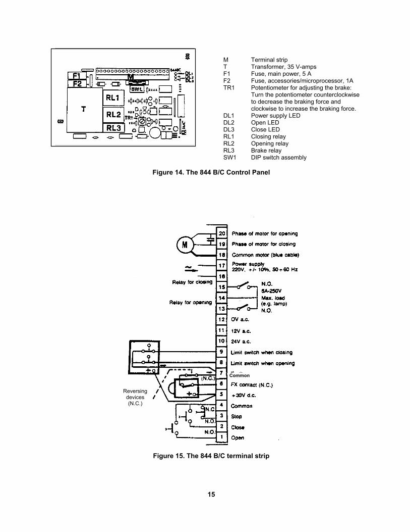
and making sure that the entire gate system meets all applicable electrical codes. Refer to Figures 14 and 15 if your operator has the 844 B/C control panel, and refer to Figures 16 and 17 if your operator has the 844 MPS control panel. Connect your 220-VAC power source to your control panel. For the 844 B/C, connect the power source to terminals 16 and 17 (see Figures 14 and 15). For the 844 MPS, connect the power source to terminal block J8 (see Figures 16 and 17). For either control panel, connect the ground wire from your power source to the grounding lug (brass) toward the front of the open 844 Operator. Connect an activating device to terminals 1 and 2 on the 844 MPS panel or terminals 1 and 4 (for open) and 2 and 4 (for close) on the 844 B/C panel. The activating device must be normally open to operate. It momentarily closes to activate the operator.
Setting Up the Limit Switches
WARNING! Turn the main power off before you make any electrical connections or set any switches inside the cover of the 844 Operator.
The maximum travel of the gate when it opens and closes is controlled by inductive limit switches (see Figures 11 and 12). While the limit switch plates are mounted on the rack or chain, the limit switch sensors or triggers are part of the 844 Operator itself (see Figure 1). Setting up the limit switches entails (1) mounting the limit switch plates on your rack or chain, (2) connecting the limit switch sensor to the control panel, and (3) checking your limit switches for correct mounting. Mount the Limit Switch Plates, General Principles: The limit switch plates furnished with the operator activate the limit switch. For the rack and pinion drive, the limit switch plates are fixed on the top of the rack at each end of the gate leaf (see Fig. 11). In the case of the chain drive, they are fixed to the top of the chain on each end of the gate leaf (see Fig. 12). For either drive, the distance between the plates and the limit switch located on the gate side of the 844 Operator should be 3/16 in. (5 mm). The limit switch plates should be positioned on the rack or chain to enter the magnetic field of the limit switch when the gate is still about 2 in. (50 mm) from the fully opened or fully closed position. The 2-in. (50-mm)
distance allows for braking.
WARNING! Turn the main power off before you make any electrical connections or set any switches inside the cover of the 844 Operator.
Mount the Limit Switch Plates, Actual Mounting: To mount the limit switch plates, first disengage the operator’s motor with the Manual Release and then fully open the gate by hand. Between the gate leaf and the operator, hold one plate in your hand just above the rack or chain on the closing gate post end and within 3/16 in. (5 mm) of the limit switch. Move the limit switch plate in your hand in the direction of gate’s opening travel.
Limitswitchtrigger
Limitswitchplate
Limitswitch
Figure 11. The limit switch assembly for a rack and pinion assembly
Limit switch
Limit switch trigger
Limit switch platemounted on the chain
Figure 12. The limit switch assembly on a chain
drive installation Watch the control panel light-emitting diodes (LEDs). The point where the FCA light (or Open LED) on the control panel goes out is the triggering point of the limit switch. You need to continue moving the limit switch plate 1-3/4 in. (45 mm) farther in the gate’s opening
14
direction in order to allow for braking distance. Spot-weld or mount the limit switch plate in this position. You repeat this same procedure for the limit switch for the gate’s closing travel using the other end of the gate leaf. Put the gate leaf in the closed position and use the FCC light (or Close LED) as the trigger indicator. Note that each limit switch plate must be located 1-3/4 in. (45 mm) in advance of the limit switch trigger point to allow for smooth braking. Connect the Limit Switches to the Control Panel: Next, you need to wire the limit switch sensors to the control panel according to your gate installation (see Figures 13 and 17 for the 844 MPS and Figure 15 for the 844 B/C). Check the Limit Switches for Correct Positioning: To check limit switch positioning, close the gate, disengage the motor with the Manual Release, and select the E1 or B operating logic on the control panel (see page 6). Turn on the power and generate an input signal. The motor will turn in the opening direction but the gate will not move because the motor is disengaged.
Note: On the 844 MPS (only) control panel, an attached warning light flashes every 1/4 sec and the control panel makes a rapid clicking sound if the limit switch cable becomes disconnected or if both limit switches are triggered at the same time. Correct the cabling and/or cycle your main power off then on and/or press the Reset button to correct the alarm condition on the control panel.
Next, move the gate by hand in the opening direction. As the limit switch plate moves by the limit switch, the motor should turn off. If the limit switch plate does not stop the motor from running when it passes the near end of the limit switch assembly, change the cable connec-tion for the limit switches (see Figure 13 or 15). Generate another input signal to start the motor in the direction of the gate’s closing. Move the gate by hand to the fully closed position. The limit switch should again shut off the motor. If the limit switch is functioning properly, engage the operator’s motor with the Manual Release lever and signal the gate to operate. If the gate operates properly, the limit switch plates can be welded securely to their anchoring points.
(a) left closing rack and pinion gate
(b) right closing rack and pinion gate
(c) left closing chain gate
(d) right closing chain gate
J3 J4
J3 J4
J3 J4
J3 J4
Figure 13. On the 844 MPS control panel, connect the limit switch ribbon cable for your rack and pinion or chain drive gate
15
M Terminal strip T Transformer, 35 V-amps F1 Fuse, main power, 5 A F2 Fuse, accessories/microprocessor, 1A TR1 Potentiometer for adjusting the brake:
Turn the potentiometer counterclockwise to decrease the braking force and clockwise to increase the braking force.
DL1 Power supply LED DL2 Open LED DL3 Close LED RL1 Closing relay RL2 Opening relay RL3 Brake relay SW1 DIP switch assembly
Figure 14. The 844 B/C Control Panel
Figure 15. The 844 B/C terminal strip
Common
Reversing devices (N.C.)
16
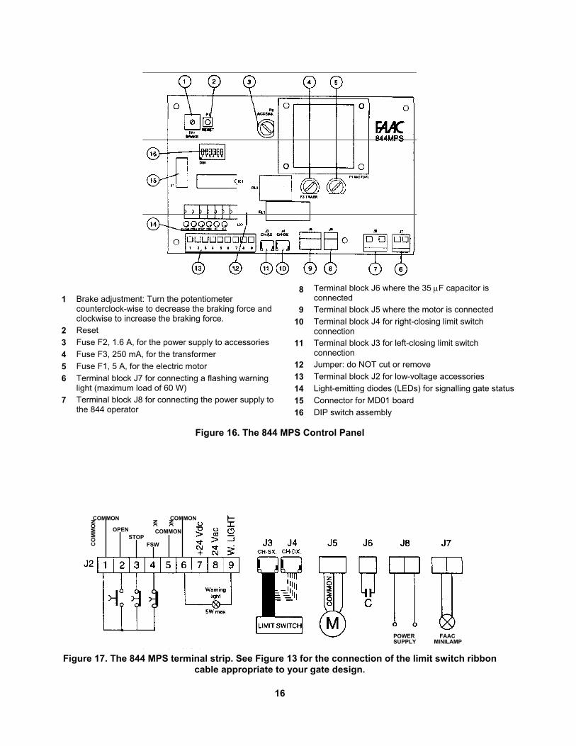
1 Brake adjustment: Turn the potentiometer counterclock-wise to decrease the braking force and clockwise to increase the braking force.
2 Reset 3 Fuse F2, 1.6 A, for the power supply to accessories 4 Fuse F3, 250 mA, for the transformer 5 Fuse F1, 5 A, for the electric motor 6 Terminal block J7 for connecting a flashing warning
light (maximum load of 60 W) 7 Terminal block J8 for connecting the power supply to
the 844 operator
8 Terminal block J6 where the 35 µF capacitor is connected
9 Terminal block J5 where the motor is connected 10 Terminal block J4 for right-closing limit switch
connection 11 Terminal block J3 for left-closing limit switch
connection 12 Jumper: do NOT cut or remove 13 Terminal block J2 for low-voltage accessories 14 Light-emitting diodes (LEDs) for signalling gate status 15 Connector for MD01 board 16 DIP switch assembly
Figure 16. The 844 MPS Control Panel
FAAC MINILAMP
POWER SUPPLY
CO
MM
ON
CO
MM
ON
CO
MM
ON
OPENSTOP
FSW
COMMON
COMMON
COMMON
Figure 17. The 844 MPS terminal strip. See Figure 13 for the connection of the limit switch ribbon
cable appropriate to your gate design.
17
Checking the Motor’s Direction of Rotation If you are using the 844 B/C control panel, you next need to check the direction of the motor’s rotation.
Note: If you are using the 844 MPS control panel you do not need to check the direction of rotation.
To check the motor’s direction of rotation, first make sure the motor is disengaged with the Manual Release. Then, move the gate by hand to the half-open position. Now re-engage the motor with the Manual Release.
Caution: If you check the motor’s direction of rotation before you install the limit switch plates, you must prevent the gate from completely opening or closing by quickly sending a second input signal to stop the gate. You may damage the gate if it fully opens or closes without the smooth-braking function of the limit switch plates.
Next turn on the main power. Send an input signal to the operator with the activating device. The gate should open. If it closes, turn off the main power. You need to reverse the brown and black motor leads on the terminal strip of the control panel. Once you have reversed the motor leads, re-check the direction of the motor’s rotation.
Adjusting the Braking The 844 Operator provides up to 2 in. (5 cm) of distance for braking the travel of the gate leaf before it actually stops. You can adjust the force of the braking and this distance with a potentiometer (see Figure 14 or 16, depending on your control panel).
• Turn the potentiometer clockwise to decrease the braking distance and increase the force of the braking.
• Turn the potentiometer counterclockwise to increase the distance of the braking and decrease the force of the braking.
Caution: To prevent any stress to the operator, be sure to leave about 3/4 in. (2 cm) between the fully closed or opened gate leaf and any physical limit stop.
Connecting Other Accessories
WARNING! Turn the main power off before you make any electrical connections or set any switches inside the cover of the 844 Operator.
The 844 B/C Control Panel: Connect other normally
open (N.O.) opening devices in parallel to terminals 1 and 4. Connect N.O. closing devices (in parallel) to terminals 2 and 4. Devices to stop the gate should be normally closed (N.C.) and should be connected (in series) to terminals 3 and 4. If your gate has no stopping device, make sure a jumper is installed instead between terminals 3 and 4. Connect all N.C. reversing devices in series to terminals 7 and 8 on the 844 B/C panel (Figure 15). If no reversing devices are installed, then you must install a jumper between the terminals.
WARNING! Turn the main power off before you make any electrical connections or set any switches inside the cover of the 844 Operator.
The 844 MPS Control Panel: Connect other normally open (N.O.) activating devices in parallel to terminals 1 and 2. Devices to stop the gate should be normally closed (N.C.) and should be connected (in series) to terminals 1 and 3. If your gate has no stopping device, make sure a jumper is installed instead between terminals 1 and 3. Connect all N.C. reversing devices in series to terminals 4 and 5 on the 844 MPS panel (Figure 17). If no reversing devices are installed, then you must install a jumper between these terminals. Connect accessories that require 24 VAC power to terminals 6 and 8.
Adjusting the Clutch Torque For safety reasons, a torque adjustment is incorporated in the 844 Operator. According to FAAC safety standards, the gate should stop when it meets with a force of approximately 33 lb (15 kg). To adjust the torque pressure, turn off the main power. Next, hold the drive shaft with a 15 mm open end wrench and, using a 6 mm Allen wrench, turn the clutch adjustment screw clockwise to increase the torque and counterclockwise to lessen the torque (see Figure 1). Increased torque means more force is required to stop the gate.
Caution: Do not over tighten the clutch adjustment screw or you may damage the clutch pin.
The torque setting can be adjusted to suit individual requirements by estimating the force of the gate with your hand. The gate should always stop when coming up against a force of about 33 lb (15 kg).
18
Setting the DIP Switches The control panel you install with the 844 Operator has a DIP switch assembly. Set the switches for your board as described below. The 844 B/C Control Panel The DIP switches on the 844 B/C control panel control the operating logic of the 844 Operator (see page 6 for more detail about the logics available on the 844 B/C control panel).
Logic DIP Switch 1 2 3 4 5 6 7 8
B On On On On Off Off Off OffC Off Off Off Off On On On On
CB On Off On Off On Off On OffBC Off On Off On Off On Off On
The only other function of the 844 Operator that can be set with the 844 B/C control panel is the force of the braking. See Figure 14 for more information. The 844 MPS Control Panel The 844 MPS control panel has six DIP switches that control various gate functions: logic, pause time, warning light behavior, and preflashing of the warning light. You must set the DIP switches for the proper functioning of the 844 Operator.
Logic Set DIP switches 1 and 2 for the logical operating mode that the gate requires (see page 7 for more information):
Logic DIP Switch 1 2
E1 On On A1 On Off S1 Off Off S2 Off On
Pause Time For operating logics A1, S1, and S2, you must set the time you want the gate to pause between opening and closing. The setting you make depends on the logic you have already set with DIP switches 1 and 2. If you have
not yet set the logical operating mode, do so before you set the pause time. Use the following table to set your pause time.
Note: All pause times listed in the following table include the time used for preflashing.
Pause Time, sec, for Logical Operation
DIP Switch
A1 S1 S2 3 4 5 15 5 On On
10 30 10 Off On 30 60 30 On Off
120 180 120 Off Off Warning Light Logic DIP switch 5 controls how the warning light behaves when the gate is closing. The table below shows your choices. The warning light has the following behaviors during other phases of operation:
• It is always off when the gate is closed. • It is always on when the gate is opening. • It is always on when the gate is fully opened
and pausing.
Behavior of the Warning Light During Closing
DIP Switch 5
On steadily On Flashing Off
Preflashing of the Warning Light DIP switch 6 controls the flashing of the gate’s warning light for 5 sec before the gate moves according to the scheme shown in the following table:
Preflashing DIP Switch 6
Yes On No Off
Finishing the Installation To finish the installation, be sure the motor is engaged with the Manual Release and that the unit is operating in the correct logic. Be sure to replace and lock the cover over the control panel.
19
Maintenance WARNING! Turn the main power to the operator off before performing any maintenance or repair operations. The manufacturer recommends that only qualified personnel check and maintain the equipment.
The FAAC recommended maintenance schedule varies according to the frequency of use of the operator, whether lightly used (once or twice an hour on average) or heavily used (many times an hour on average). 1. Check the oil. To check the oil level, remove the plastic oil filler cap inside the cover of the operator (see Fig. 1) to verify the oil covers the copper coil of the motor. If more oil is needed, add it through the oil filler cap. Be sure to use only FAAC XD 220 or Shell/Tellus #15 oil.
Light use: check once every other year Heavy use: check every year
2. Check the clutch adjustment and Manual Release. You need to periodically check that the clutch adjustment still meets safety standards. Also, be sure that the Manual Release mechanism works and the key is handy for emergencies.
Light use: once per year Heavy use: every 6 months
3. Check all reversing devices. Once every six months you check that all reversing devices installed on the gate work properly.
20
Troubleshooting WARNING! Turn the main power to the operator off before performing any maintenance or repair operations. The manufacturer recommends that only qualified personnel check and maintain the equipment.
If you have a problem installing the operator, check the problems and solutions listed below and refer to the troubleshooting chart on the next page. Problem: The operator does not respond to the activating signal. Solutions: Make sure the main power switch is on. Check the control panel terminal strip for possible broken or disconnected wires. If a radio signal is being used to activate the operator, be sure the code sets on both the transmitter and receiver are the same. Momentarily short across terminals 1 and 2 on the MPS control panel, or terminals 1 and 4 or 2 and 4 on the B/C control panel. If this activates the operator, a problem probably exists in the activating device itself. Problem: The gate is closed and does not open. Solutions: Make sure the clutch adjustment is not too weak. Increase the torque if the motor is running and the gate is not moving. This may be necessary for especially heavy gates. Check that the closed limit switch is working. The FCC status light (or Open LED) should be off. Make sure that the limit switch plate is not too far away from the limit switch. The distance between a plate and the switch should be 3/16 in. (5 mm). Check fuse F1 and replace it if necessary. Problem: The motor is running in the wrong direction.
Solutions: Reverse the brown and black motor power leads on the 844 B/C control panel. Problem: The gate opens, but will not close. Solutions: If there are no optional reversing devices connected to the control panel, make sure a jumper is installed between terminals 4 and 5 on the MPS control panel or 6 and 7 on the B/C control panel. If optional reversing devices have been installed, check them to see if they are working properly (an activated reversing device will prevent the gate from closing). Temporarily short across the relevant terminals to bypass the reversing devices to see if the gate closes. If the gate closes, then the problem exists within the reversing device(s). Problem: The gate opens and the operator continues to run. Solutions: Check the FCC light (or Close LED) on the control panel. It should be off. If it is not, check the alignment of the limit switch plate. If the FCC light is not off and the limit switch plate is correctly adjusted, then replace the limit switch.
Note: If the limit switch plates are not detected by the limit switch on an operator with the 844 B/C control panel, the operator will run for approximately 240 seconds and then stop. For an operator with the 844 MPS control panel, the motor will run for 120 seconds, and then the control panel will be in alarm status.
21
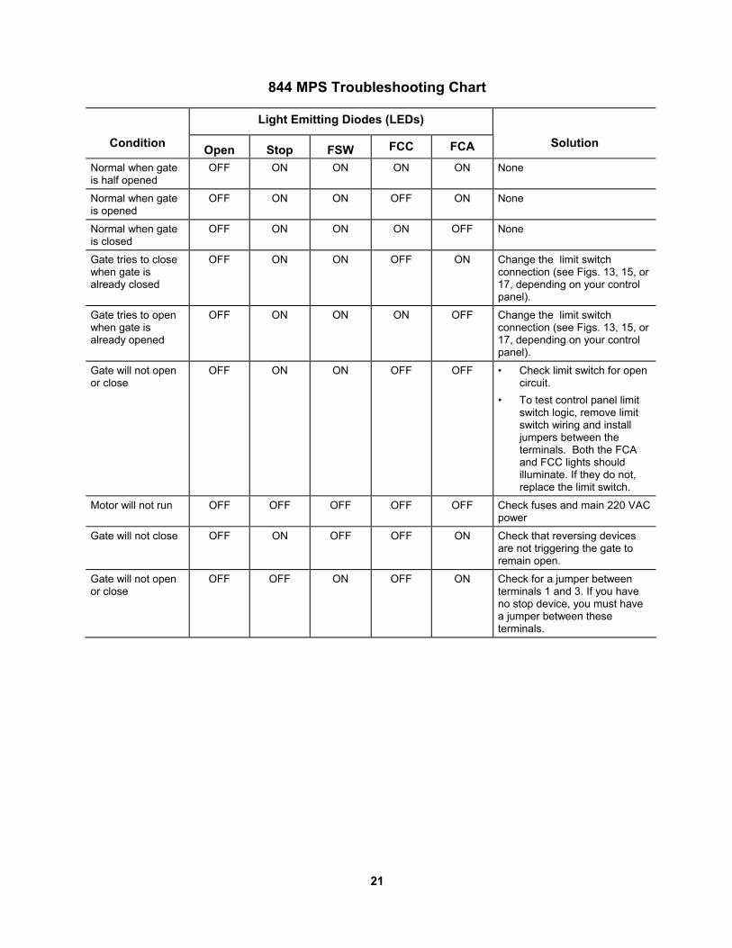
844 MPS Troubleshooting Chart
Light Emitting Diodes (LEDs)
Condition Open Stop FSW FCC FCA Solution
Normal when gate is half opened
OFF ON ON ON ON None
Normal when gate is opened
OFF ON ON OFF ON None
Normal when gate is closed
OFF ON ON ON OFF None
Gate tries to close when gate is already closed
OFF ON ON OFF ON Change the limit switch connection (see Figs. 13, 15, or 17, depending on your control panel).
Gate tries to open when gate is already opened
OFF ON ON ON OFF Change the limit switch connection (see Figs. 13, 15, or 17, depending on your control panel).
Gate will not open or close
OFF ON ON OFF OFF • Check limit switch for open circuit.
• To test control panel limit switch logic, remove limit switch wiring and install jumpers between the terminals. Both the FCA and FCC lights should illuminate. If they do not, replace the limit switch.
Motor will not run OFF OFF OFF OFF OFF Check fuses and main 220 VAC power
Gate will not close OFF ON OFF OFF ON Check that reversing devices are not triggering the gate to remain open.
Gate will not open or close
OFF OFF ON OFF ON Check for a jumper between terminals 1 and 3. If you have no stop device, you must have a jumper between these terminals.
22

Limited Warranty To the original purchaser only: FAAC International, Inc., warrants, for twenty-four (24) months from the date of invoice, the gate operator systems and other related systems and equipment manufactured by FAAC S.p.A. and distributed by FAAC International, Inc., to be free from defects in material and workmanship under normal use and service for which it was intended provided it has been properly installed and operated. FAAC International, Inc.'s obligations under this warranty shall be limited to the repair or exchange of any part of parts manufactured by FAAC S.p.A. and distributed by FAAC International, Inc. Defective products must be returned to FAAC International, Inc., freight prepaid by purchaser, within the warranty period. Items returned will be repaired or replaced, at FAAC International, Inc.'s option, upon an examination of the product by FAAC International, Inc., which discloses, to the satisfaction of FAAC International, Inc., that the item is defective. FAAC International, Inc. will return the warranted item freight prepaid. The products manufactured by FAAC S.p.A. and distributed by FAAC International, Inc., are not warranted to meet the specific requirements, if any, of safety codes of any particular state, municipality, or other jurisdiction, and neither FAAC S.p.A. or FAAC International, Inc., assume any risk or liability whatsoever resulting from the use thereof, whether used singly or in combination with other machines or apparatus. Any products and parts not manufactured by FAAC S.p.A. and distributed by FAAC International, Inc., will carry only the warranty, if any, of the manufacturer. This warranty shall not apply to any products or parts thereof which have been repaired or altered, without FAAC International, Inc.'s written consent, outside of FAAC International, Inc.'s workshop, or altered in any way so as, in the judgment of FAAC International, Inc., to affect adversely the stability or reliability of the product(s) or has been subject to misuse, negligence, or accident, or has not been operated in accordance with FAAC International, Inc.'s or FAAC S.p.A.'s instructions or has been operated under conditions more severe than, or otherwise exceeding, those set forth in the specifications for such product(s). Neither FAAC S.p.A. or FAAC International, Inc., shall be liable for any loss or damage whatsoever resulting, directly or indirectly, from the use or loss of use of the product(s). Without limiting the foregoing, this exclusion from liability embraces a purchaser's expenses for downtime or for making up downtime, damages for which the purchaser may be liable to other persons, damages to property, and injury to or death of any persons. Neither FAAC S.p.A. or FAAC International, Inc., assumes nor authorizes any person to assume for them any other liability in connection with the sale or use of the products of FAAC S.p.A. or FAAC International, Inc. The warranty hereinabove set forth shall not be deemed to cover maintenance parts, including, but not limited to, hydraulic oil, filters, or the like. No agreement to replace or repair shall constitute an admission by FAAC S.p.A. or FAAC International, Inc., of any legal responsibility to effect such replacement, to make such repair, or otherwise. This limited warranty extends only to wholesale customers who buy directly through FAAC International, Inc.'s normal distribution channels. FAAC International, Inc., does not warrant its products to end consumers. Consumers must inquire from their selling dealer as to the nature and extent of that dealer's warranty, if any. This warranty is expressly in lieu of all other warranties expressed or implied including the warranties of merchantability and fitness for use. This warranty shall not apply to products or any part thereof which have been subject to accident, negligence, alteration, abuse, or misuse or if damage was due to improper installation or use of improper power source, or if damage was caused by fire, flood, lightning, electrical power surge, explosion, wind storm, hail, aircraft or vehicles, vandalism, riot or civil commotion, or acts of God.
FAAC International, Inc. 303 Lexington Avenue Cheyenne, WY 82007
844 IM, 6/98