Embed Size (px)
DESCRIPTION
NASA Apollo historical summary report
Citation preview
General Disclaimer
One or more of the Following Statements may affect this Document
This document has been reproduced from the best copy furnished by the
organizational source. It is being released in the interest of making available as
much information as possible.
This document may contain data, which exceeds the sheet parameters. It was
furnished in this condition by the organizational source and is the best copy
available.
This document may contain tone-on-tone or color graphs, charts and/or pictures,
which have been reproduced in black and white.
This document is paginated as submitted by the original source.
Portions of this document are not fully legible due to the historical nature of some
of the material. However, it is the best reproduction available from the original
submission.
Produced by the NASA Center for Aerospace Information (CASI)
t----.· . --- "-_--.-.-----."'-_--. ~ .. " ~ ....... ' ~.~,' .'
__________ - BELL AEROSYSTEMS COMPANY __________ _
t 1 i 1
I , i 1 I • ; I 1 1 i j
1 I 1 i j , i 1 i ! I 1 \ '/ ,
OIVISION 0,. PELot. AERo~rI.CL CORPORATION
i • • :
N.2Jt:ruMl.3 'i 914~~-&3 U ITHRU,
S !
"PACEa. --:--1\== ___ _ t\. .)~ 1'\ ICODQ c" ... \\:) ~~ \\ . d'
APOLLO RCS POSITIVE EXPULSION Tf_ .... TKAGE PRODUCT IMPROVEMENT PROGHAil [
FINAL REPORT - TASK A
EVOLUTION OF APOl .. LO-TYPE POSITIVE EXPULSION "pROPELLANT TANKAGE
Bell Report No. 8514-927002 26 September 1969
(Supersedes Initial Submittal of 12-31-67)
By
Robert K. Anderson and Elvin J. Ecelbarger
Prepared Under COl:tract No. NAS9-7182
By
Bell Aerosystems Company Buffalo, New York
For
National Aeronautics and Space Administration Marmed Spacecraft Center
Houston, Texas
•
•
. 1 i
J
I , j
!
f" "
,.~
I ;! ,
. ;".'
__________ fJ(;LL Af::ROSYSTEMS COMP"'N~ ----------
_ 2
M'OLLO RCS POSITIVE EXPULSION TANKAGE PRODUCT IMPROVEMENT PROGRAM
FINAL REPORT - TASK A
EVOLUTION OF APOLLO-TYPE POSITIVE EXPULSION PROPELLANT TANKAGE
Bell Report. No. 8514-927002 26 September 1969
(Supersedes Initial submittal of' 12-31-67)
By
Robert K. Anderson and Elvin J. Ecelbarger
Prepared Under contract No. NAS9-71S2
By
Bell Aerosystems Company Buffalo. New York
For
National Aeronautics and Space Adminis~ration Manned Spacecraft Center
Houston. Texas
, fi Ii , j i , I j
, , , ., .1 < • . , j "
:l
J J , ,j
,i ')
,1 :~ '; . ..I ;,:}
".-1 .~ -. ~ ... ~ "s '.
'.~ .'/
.oJ :1
". -, .
.-,~~.
__________ BELL AEROSYSTEMS COMPANY _________ _
DIVISeON 0 .. 8E~" AEROSPACE. CORPORATION
FOREWORD
This report is one of a series of task reports which present the results of a
program performed by Bell Aer(\systems Company during the period July 1967 through
,. September 1969 under Contract NAS9-7182 for the National Aeronautics and Space
Administration, Manned Spacecraft Center. Mr. Darrell Kendrick was Technical
Monitor of the program for NASA. The Bell Aerosystems Program Manager was
Mr. R. K. Anderson.
The purpose of the program was to improve and update the Apollo RCS positive
expulsion propellant tank assemblies in the areas of performance, reliability and
mission duration. The program effort was divided into the following major tasks,
each of which is reported separately:
Task A '" Historical Summary Report - A chronological summary of the evolution
of the Command, Service, Lunar Module and other related tankage was
prepared. This summary includes data on all configurations considered
under the applicable programs and describes related IR&D work at Bell
Aerosystems.
Task B - Long Term Compatibility Testing - The purpose of this task was to determine
the useful operating lifetime of the Apollo Configuration RCS tanks as appli
cable to a mission of extended duration with a specific goal of 12 months.
This task consisted of the following sub-tasks:
B-1: Tank Assembly Storage: 'fhree tank assemblies were stored with
propellant (N204' MMH, 50/50 fuel blend) for 12 months at operating
pressure. At the end of this time each tank was subjected to a
complete propellant expulsion followed by disassembly and evaluation.
Report No. 8514-9~7002 .n
I
i J
I I \ , ! I !
--- -------------
__________ BELL AEROSYSTEMS COMPANY _________ _
giVISION OF BELL. AE,,05PAC£ CORPO"ATION
B-2: Bladder Material Compatibility Testing: Teflon bladder material
specimens were subjected to rolling of buckled fold tests aftel-
24 hours, six months, and 12 months exposure to N204' MMH and
50/50 fuel.
B-3: External Flange Seal Evaluation: The effect of initial flange bolt
tightening and retightening techniques on the rate of torque decay
during a one-year shelf storage period was evaluated.
Task C - Correlation of Referee Fluid and Propellant in Vibration Testing - The
objective of this task was to verify that vibration testing cA the Apollo
type bladder with referee fluid"is representative of vibration testing with
actual propellants. To develop a (:orrelation with sufficient accuracy, the
following three areas of testing were pursued:
C-1: Vibration tests were conducted with referee fluid in a plexiglass
tank to define the response characteristics of the bladder as affected
by ullage level, direction of excitation and vibration input level.
C-2: Rolling of buckled fold tests were conducted on bladder material
specimens to compare endurance in referee fluids with endurance
in propellants.
C-3: Full scale vibration testing was performed on a Lunar Module RCS
oxidizer tank with N204'
Task D - Elimination of Permeation and Bubble Formation - The objective of this
task was the elimination or reduction of bladder permeation and the
associated problem of bubble formation within the bladder. This task
included two prinCipal areas of effort:
Report No. 8514-927002 iii
I
__________ BELL AEROSYSTEMS COMP,'NY _________ _
OlV1510N Of Pt.,-", AEROSPACE co.-PC RATION
D-l: Development of Permeation Barrier: This sub-task consisted
of design and fabrication of a Teflon bladckr with an aluminum foil
laminate as a permeation barrier. This bladder, which was of the
Service Module oxidizer configuration, was also designed to function
in an undersized configuration.
D-2: Elimination of Bubble Formation in Current Apollo Bladder Con
figuration: Experiments were conducted on both model and full
scale tanks to examine bubble formation phenomena as a function
of such variables as temperature, pressure and ullage level. Data
from these tests were used to provide an emperical basis to better
understand the mechanisms involved and the effect of each on bubble
formation.
Task E - Solution of Command Module and Service Iviodule Oxidizer Repositioning
Problem - The objective of this task was to increase expulsion cycle life
of these bladders by eliminating damage due to post-expulsion repositioning.
E-l: Service Module Oxidizer Bladder: The approach used to solve this
problem was the use of an underSized configuration similar to that
used on the Lunar Module RCS tanks to solve the same problem.
E-2: Command Module Bladder: This problem was associated with the
twist mechanism involved in a horizontally mounted tank during the
fill cycle. A solution to this proble'!Il could not be found within the
constraints of the program.
Task F - Integration and Verification of Solutions - The objective of this task was to
devise a series of formal tests to demonstrate compliance of design changes
from Tasks D-l and E with the requirements of the applicable Apollo con
tractor procurement specification.
Report No. 8514-927002 iv
r
_________ BELL AEROSVSTEMS COMPANY _________ _
DiVISION 0,. .eLL A&RD'''.CC CORPORATION
Service Module oxidizer bladders of the undersized configuration with
an aluminum foil laminate were subjected to Qualification level vibration
testlng and were to be subjec~d to 20-propellant expulsion cycles. How
ever, problems occurred during vibration testing which resulted in bladder
failure and this task could not be completed within the limits of this program.
Since the Command Module bladder twist problem was not so~ved (Task E-2),
no Command Module tank testing was performed in Task F.
This report covers the effort performing under Task A. The other major
tasks are reported indiVidually as follows:
~ Report Number Title -B 8514-928004 Long Term Compatibility Testing
C 8514-928005 Correlation of Referee Fluid and Propellant Vibration Testing
D 8514-928003 Elimination of Permeation and Bubble Formation
E 8514-928006 Solution of Command Module and Service Module Repositionlng Problems
F 8514-928007 Integration and Verification Testing
Report No. 8514-927002 v
BELL AEROSYSTEMS COMPANY _________ _
DIVISION O~ .£~L AE"OS""Cr: CO .... ORATION
ACKNOWLEDGEMENT
'.i'he preparation and format of this report are largely the product of its co-author,
Mr. E. Ecelbarger, Supervisor of Technical Documentation for Bell Aerosystems'
structural System3 Department.
The scope, details, and historical accuracy of the contents of this report were
made POSSible by many Bell Aerosystems employees who contr'.buted their time and
efforts, even though some are no longer associated with the Apollo and other tankage
programs reported herein. Their wholehearted and generous cooperation is greatly
appreciated. Principal among these contributors are:
Report No. 8514-927002
Mr. T. Maurer
Mr. J. Z. Colt
Mr. L. M. Thompson
Mr~ C. T. Kessing
Mr. T. Glynn
Mr. J. T. Pillittere
Mr. J. Wolf
Mr. S. A. Mekarski
Mr. R. A. Peltier
Mr. C. A. Armontrout
Mr. W. Page'
Mr. B. J. Szpakowski
vi
. It t •
__________ BELL AEROSYSTEMS COMPANY _________ _
PREFACE
This report was prepared by Bell Aerosystems Company in response to
Task A of NASA Contnct NAS9-7182, "Apollo Command Module, Service Module,
and Lunar Module RCS Positive Expulsion Tankage Product Improvement
Program."
, The objective of this program, Bell Modd No. 8514, is to improve and up-
grade the Apollo RCS tankage in the areas of performance, reliability, and miSSion
duration.
The purpose of this report is to provide a summary of the total effort on
each of the mainstream Apollo-type tankage and associated programs and in
addition show the relationships between them. This effort encompasses ten
separate programs during the period of Oc~ober 1962 to December 1968. These
programs were aligned to a common technology concept; however, they were
individual contracts performed for different contractors. Although the programs
were conducted on a common baSiS, each program had its own sequence of events.
The information in this report is presented to document technical activity
and show the chronological sequence of events. The intent is to report this
activity in sufficient detail so that future repetition of effort can be avoided.
Although there is an abundance of test information, detailed test results are
included only if they w~re significant for tank assembly design or performance.
Report No. 8514-927002 vii
"U.'1' f7(rtn' F-rf$~i1R;.*75:a [ ''''~'l#-Sn~·\rnwrt'-it'Hb.-· foot it· t'Me " ccr (j "'r.-.'· .... *" It" t. n," I ,"l '''?ti
__________ BELL AEROSYSTEMS COMPANY _________ _
DIVISION 0' O£LI.. A£IIIIOSPACE COIIIIPORATION
The report is organized in sections as follows:
SECTION I - INTRODUCTION
This section briefly identifies and describes the. Bell supplied positive expulsion propullant tankage used on the Apollo vehicle and the experience base existiug at the inception of these programs.
SECTION n - APOLLO TYPE TANKAGE CONTRACT SUMMARY
This section describes the common technology or "commonality" concept used as a basis for the five mainstream tankage programs and identifies the five associated projects which were used to supplement them. The chronological and technical relationships of these ten programs are presented and in addition pertinent reference information regarding the tank assembly testing and physical and performance characteristics are included in tables and illustrations.
SECTION ill - MAINSTREAM TANKAGE AND
ASSOCIATED PROGRAM HISTORIES
Because of the basic individuality of the programs, a separate subsection is used for each program. Each subsection contains a chronological history for a particular program with specific reference to events on other programs only wh"n they had significant bearing on the activity. The chronological occurrence of major events and detailed test sequencing for the mainstream programs is presented in charts for reference use, and the supporting text includes at least mention of all salient points. .
SECTION IV - MANUFACTURING AND QUALITY CONTROL
The information in this section is organized by compcnent to document the major fabrication and assembly activity.
SECTION V - RE LIABILITY
The reliability summary is generalized for all programs with the Lunar Module tankage ·used for speCific reference.
Report No. 8514-927002 viii
---------~--.------------------------------------~--~-
-----~-
---~-
__
__
__
__
__
BE
LL
AE
RO
SY
ST
EM
S C
OM
PA
NY
_
__
__
__
__
_ _
r • , ". !
~ _,~-,'J..
," ;; ...
OI:w'ISIO~
OF
a£L~
AE
RO
SP
AC
E
CO
RP
OR
AT
iON
",'
" /
/ , ,
! {
.J
.. r ~J
t f 2 , ,
,-J "
".'
,. 1 :
. , .,
. "
Rep
ort N
o. 85
14
-92
70
02
"-\
. ,
, .;
; ."
" "
.,' /"
./ '." :.:. ;.:
~=
.. ,"~.:" I j
ix
~~ C
,'l
< ..... ~
.
;<.j
< f~
Z
0 ... ~
:J p< ~,
r .. ~1
~ E:: t" 0 III 0 ~, o-l 0 P
i <
..
___ ....... ' M"" .... ., IA'¥ t '#'. .'.*. c(" totno t l' " r~!!ttl ") t tOr"f .",' -oS' e'. f ....
. . __________ BELL AEROSYSTEMS COMPANY __________ _
Section
I
II
DIVISION OF BELL A':fIIOSPACE C:O"PQ"4TION
CONTENTS
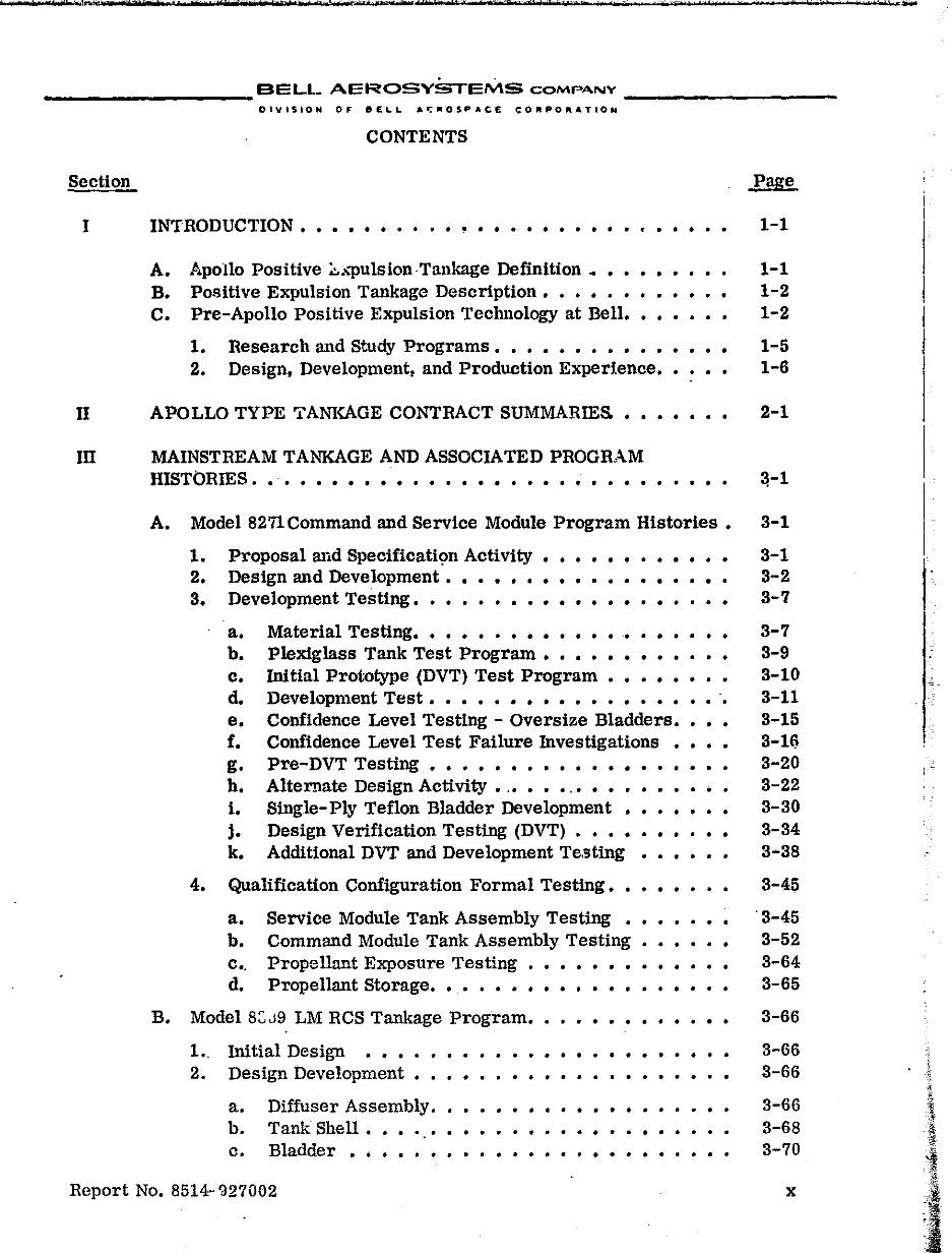
INTRODUCTION. • • • • • • • • • • • • • • • • • • • • • • • • • •
A. B. C.
Apollo Positive ~."llulsion ·Tankage Definition 4 •••••••
Positive Expulsion Tankage Description. • • • • • • •• Pre-Apollo Positive Expulsion Technology at Bell. • • • •
• • • • •
1. 2.
Research and Study Programs. • • • • • • • • • • • Design. Development, and Production Experience ••
• • • • • •
APOLLO TYPE TANKAGE CONTRACT SUMMARIES. •• • • • • •
III MAINSTREAM TANKAGE AND ASSOCIATED PROGRAM HISTORIES. . . . . • • • • • . . . • • • . . • • ~ • . • • • • • • •
A. Model 8271Command and Service Module Program Histories.
1. 2. 3.
4.
Proposal and Specification Activity •••• Design and Development •••••••••• Development Testing. • • • • • • • • • • •
• • • • • • • • •
• •• • • • • • • • • • • •
a. b. c. d. e. f. g. h. i. j. k.
Material Testing. • • • • • • • • • • • P1exiglass Tank Test Program •••• Initial Prototype (DVT) Test Program
• • • • • •
• • • • • • • • • • • • • • • • • •
Development Test. • • • • • • • • • • • • • • • • • • Confidence Level Testing - Oversize Bladders •••• Confidence Level Test Failure Investigations • • • • Pre-DVT Testing . . . • . . . . . . . . • . . . . . . Alternate Design Activity •.••••.•••••••••• Single-Ply Teflon Bladder Development • • • • • • • Design Verification Testing (DVT) • • • • • • • • • • Additional DVT and Development Te.sting • • • • • •
Qualification Configuration Formal Testing. • • • • • • •
a. b. c •. d.
• • • Service Module Tank Assembly Testing • • • • Command Module Tank Assembly Testing • Propellant Exposure Testing • • • • • • • Propellant Storage. • • • • • • • • • • • • • • • •
• • • • • • • • • • •
• •
B. Model 8:;J9 LM RCS Tankage Program •• • • • • • • • • • •
1.. Initial Design • • • • • • • • • • • • • • • • • • • • • • • 2. Design Development • • • • • • • • • • • • • • • • • •
a. Diffuser Assembly. • • • • • • • • • • • • • • · • b. Tank Shell • • • · • • • • • • • • • • • • • • • • • • c. Bladder • • • • • • • • • • • • • • • • • • • • • • •
Report No. 8514-'327002
Page
1-1
1-1 1-2 1-2
1-5 1-6
2-1
~-1
3-1
3-1 3-2 3-7
3-7 3-9 3-10 3-11 3-15 3-16 3-20 3-22 3-30 3-34 3-38
3-45
'3-45 3-52 3-64 3-65
3-66
3-66 3-66
3-66 3-68 3-70
x
'r .TV!l .-l!W.oI
I ,-
, 1
BELL AEROSYSTEMS COMPANY _________ _
Section
m (cont)
C.
3.
4.
5.
6.
CONTENTS (CONT)
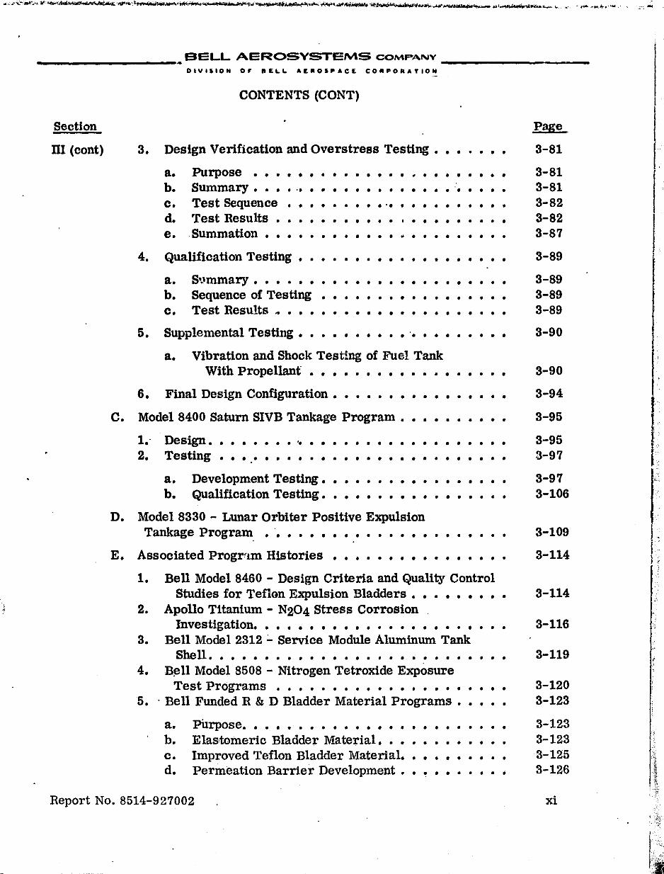
Design Verification and Overstress Testing • • • • • •
a. b. c. d. e.
Purpose ••• Summary ••• Test Sequence 'fest Results •
· . . . . . . . . . . ~ . . . . . . . . ... . . . . . . . . . . . . . '. . ... · ........ ' .......... . • • • • • • • • •• •••••••••
. Summation • • • • • • • • • • • • • • • • • • • • • •
Qualification Testing • • • • • • • • • • • • • •• • • • •
a. b. c.
S'Jmmary •••..• Sequence of Testing Test Results .• • • •
• • • • • • • • • • • • • • • • • • • • • • • • • • • • • • • • • • • • • • • • • • • • • • • • • • •
Supplemental Testing • • • • • • • • • · .. • • • • • • • •
a. Vibration and Shock Testing of Fuel Tank With Propellant • • • • • • • • • • • • • • • •
Final Design Configuration • • • • • • • ••• • •••
• •
• •
Model 8400 Saturn SIVB Tankage Program • • • • • • •• • •
1 .. Design ..••.... I •••• • • • • • • • • • • •• • • • 2. Testing .•• . ' • . . • . • . • • • • • • • • . • • • • ••
a. b.
Development Testing • Qualification Testing •
• • • • • • • • • • • • • • • • • • • • • • • • • • • • • • • •
D. Model 8330 - Lunar Orbiter Positive Expulsion Tankage Program, .'. . . • • . • . . . . • . • . • . • . . .
E. Associated Progrr!m Histories • • • • • • • • • • • • • • • •
1. Bell Model 8460 - Design Criteria and Quality Control Studies for Teflon Expulsion Bladders • • • • • • • • •
2. Apollo Titanium - N204 Stress Corrosion Investigation. . . . • • • • • • . . . . . • • • . • . • •
3. Bell Model 2312 ;.. Service Module Aluminum Tank Shell. . . . . . . . . . . . . . . . . . . . . . . . • • •
4. B~ll Model 8508 - Nitrogen Tetroxide Exposure Test Programs . . . . . . . . . . . • . . . . . . . • .
5 •. Bell Funded R&D Bladder Material Programs •••••
a. pUrpose. • • • • • • • • • • • • • • • • • • • • • • • b. Elastomeric Bladder Material. • • • • • • • • • • • c. Improved Teflon Bladder Material. • • • • • • • • • d. Permeation Barrier Development • • • • • • • • • •
Report No. 8514-927002
Page
3-81
3-81 3-81 3-82 3-82 3-87
3-89
3-89 3-89 3-89
3-90
3-90
3-94
3-95
3-95 3-97
3-97 3-106
3-109
3-114
3-114
3-116
3-119
3-120 3-123
3-123 3-123 3-125 3-126
xi
I
r
I.
I
I' ."
. ,?'
__________ BELL AEROSYSTEMS COMPANY __________ _
Section
IV
v
D-IVtSIOH 0,. BE~~ AEROSPACE CORPORATION
CONTENTS (CONT)
MANUFACTURING AND QUALITY CONTROL". • • • • • • • • • •
A. 'rank Shell Fabrication. .' • • • • • • • • • • • • • • • • • • •
1. 2.
Processing Sequence Fabrication Problems
a. Wall Thickness •
• • • • • • • • • • • • • • • • • • •
• • • • • • • • • • • • • • • • • • •
• • • • • • • • • • • • • • • • • • •
Page
4-1
4-2
4-2 4-4
4-4 b. Mismatch...................... 4-5 c. Porosity........................ 4-5 d. Weld Bead Height, Width and Drop Through • • • •• 4-6
B. Bladder Fabrication • • • • • • • • • • • • • • • • • • • • •
C.
D.
1. 2.
Processing Sequence Fabrication Problems
• • • •
• • · .. . • • • • • • • • • • • • • • • • • • • • • • • • • • • •
Diffuser Assembly Fabrication. • • • • • • • • • • • • • • • •
1. 2. 3. 4. 5.
Bimetallic Joints ••• Flange-to-Cone Weld
• • • • • • • • • • • • • • • • • • • • • • • • • • • • • • • • • • • • • •
Drilling. . . • • . . . . . . . • . Tube -to-Cone Weld ••••••• Bleed Tube Weld. • • • • • • • •
• • • • • • • • • • • • • • • • • • • • •
• • • • • •
• • • • • • • • • • • •
Assembly and Acceptance Test. • • • • • • • • • • • • • • • •
RELIABILITY ••••• . .. . . . . . . '.' . . . . . . . . . • • • •
A. Program Control. • • • • • • • • • • • • • • • • • • • • • • •
B. Failure Mode and Effect Analyses. • • • • • • • • • • • • • •
C. Qualitative and Quantitative Analysis • • • • • • • • • • • • •
D. Reliability Block Diagrams • • • • • • • • • • • • • • • • • •
4-6
4-6 4-8
4-9
4-10 4-10 4-11 4-11 4-12
4-13
5-1
5-1
5-1
5-2
5-2
Report No. 8514-927002 xii
I i
f
I
.'
I"' 1
_________ BELL AEROSYSTEMS COMPANY _________ _
~
1-1
1-2
1-3
IT-1
IT-2
IT-3
IT-4
II-5
III-1
III-2
III-3
III-4
III-5
III-6
.III-7
III-8
III-9
III-10
V-1
V-2
V-3
DIVIlION OF 81:1.1. AE"OS~ACE; COIJIPOftATION
FIGURES
Typical Apollo Type Tank Assembly • • • • • • • • • • • • • • •
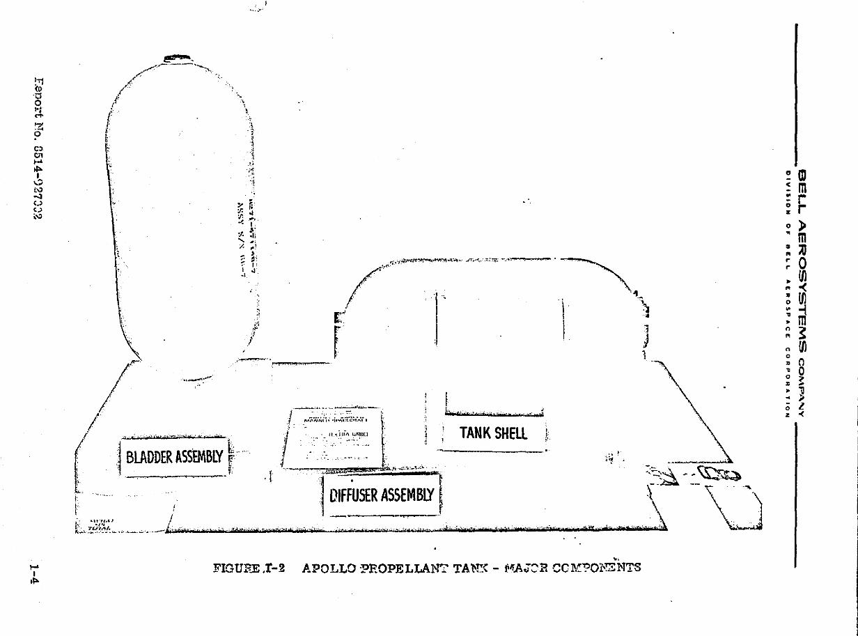
Apollo Propellant Tank - Major Components •• • • • • • • • • •
Model 8101 Agena SPS Tank Assemblies. • ••••
Apollo Positive Expulsion Propellant Tankage and
• • • • •••
Associated Programs • • • • • • • • • • • • • • • • • • • • • •
Command Module Tank Assemblies • • • • • • • • • • • • • • •
Service Module Tank Assemblies. • • • • • • • • • • • • • • • •
Lunar Module RCS Tank Assemblies. • • • • • • • • • •• • • •
Saturn APS Tank Assemblies.· • • • • • • • • • • • •••• • • •
1-3
1-4
1-9
2-2
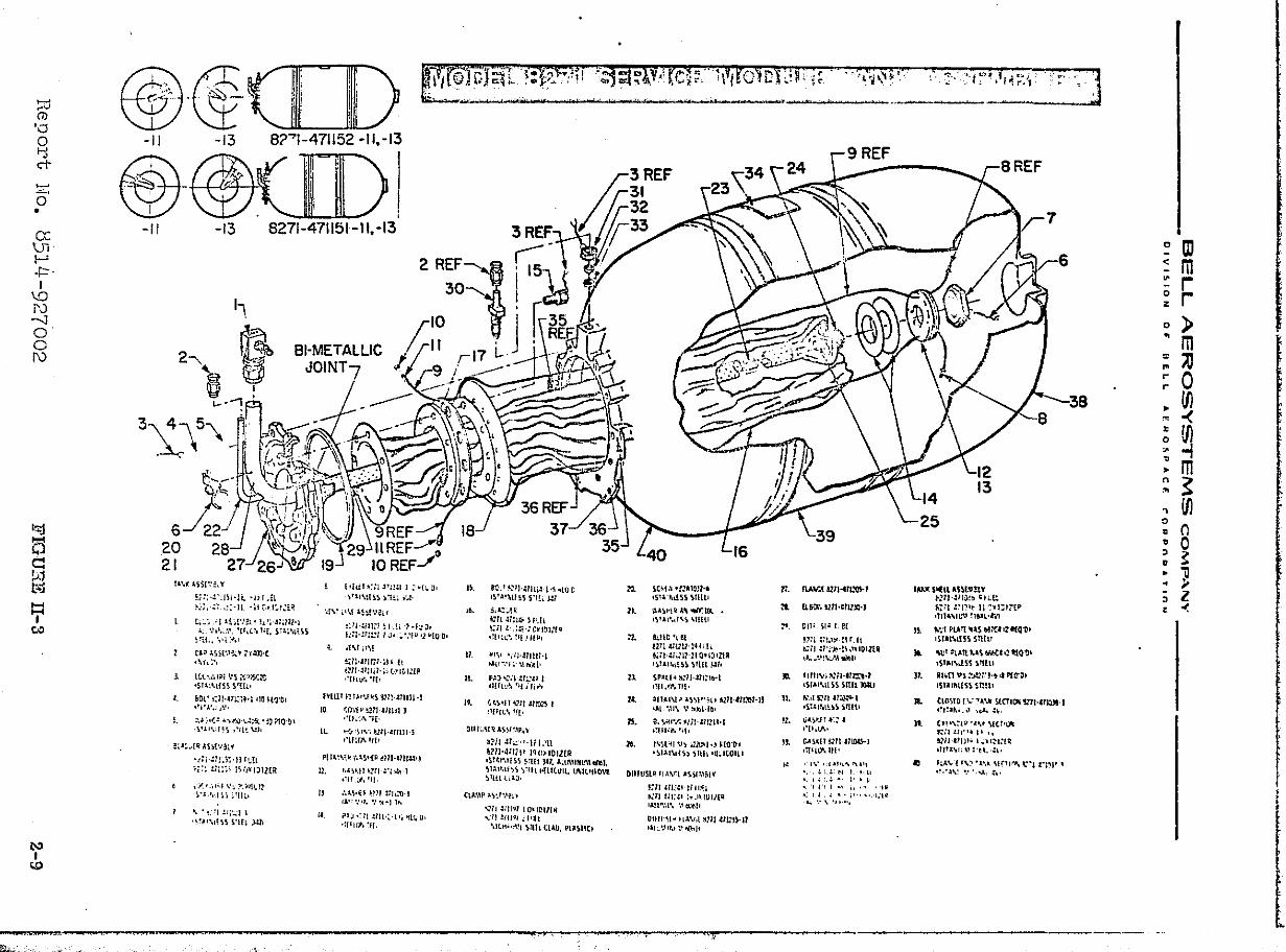
2-8
2-9
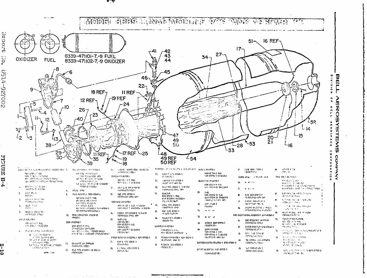
2-10
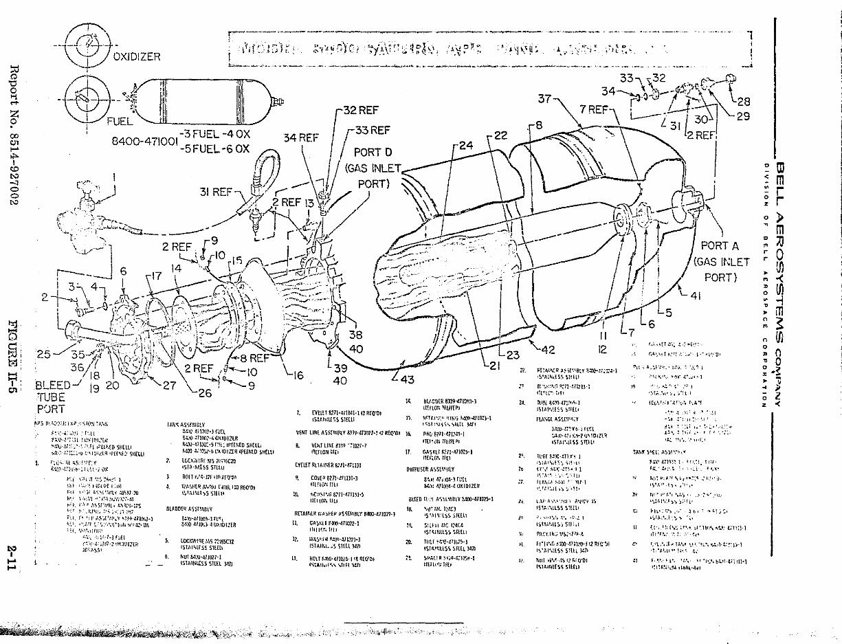
2-11
Model 8271 Command, Service Module Tankage Program History 3-3
Model 8271 3-Ply Oversize Bladder Test Summary. • • • • • • 3-14·
Model 8271 Design Alternatives Development Test Summary. • 3-24
Model 8271 DVT and Development Test Summary. • • • • • • • 3-35
Model 8271 Command and Service Module Test History. •
Model 8339 Lunar Module Tankage - Program History • •
Model 8339 Lunar Module Test History - Undersized
• • •
• • •
Bladder Configuration. • • • • • • • • • • • • • • • • • • • • •
Model 8400 Saturn SIVB Program History • • • • • • • • • • • •
Model 8330 Lunar Orbiter Program History. • • • • • • • • • •
Types of Expulsion Bladder Compositions • • • • • • • • • • • •
3·-46
3-67
3-76
3-96
3-110
3-124
Typical Positive Expulsion Tankage Functional Block Diagram. '5-4
Lunar Module - Exploded View. • • • • • • • • • • • •
ReliabilitY Logic (Block) Diagram, Positive ExpulSion Tank, Typical. . . . • • • . . . -e • • • • • • • • • •
• • • • or
• • • • •
5-5
5-6
Report No. 8514-927002 xiii
•
I
__________ BELL AEROSYSTEMS COMPANY _________ _
DIVISION 0,. 8E ...... A~"OSPAe£ CO"PORATION
TABLES
11-1 Apollo-Type Positive Expulsion Tankage - Physical Characteristics . . . • . .- . . . . • . . • . • . . . . • • • •
11-2 Apollo-Type Positive Expulsion Tankage - Qualification
11-3
III-I
I1I-2
V-I
V-2
V-3
Tes t Sequence. . . • • • . • . • . . . . . . . . . • • . • • •
Apollo-Type Positive Expulsion Tankage - Qualification Dynamic Test Requirements • • • • • • • • • • • • • • • • •
Expulsion Test Sequence •••••••• • • • • • • • • • • • •
Lunar Orbiter Propulsion System Flight History. • • • • • • •
Typical Failure Mode and Effects Analyses. • • • • • • •
Propellant Expulsion Data Summary - Apollo Type Tank
• • •
Assemblies . . . • . • . . • • . . . . . • • • ••• • • • • •
Propellant Expulsion Data Breakdown. • • • • • ••• • • • • •
Report No. 8514-927002
2-5
2-6
2-7
3-88
3-113
5-7
5-13
5-14
xiv
I
.-
"
; .. ~ .,', .
" ..
_:.... ________ BELL AEROSYSTEMS COMPANY __________ _
O'IVISIOH OF &EL.L AEfIIOSPAr.:r. CORPORATION
SECTION I
INTRODUCTION
A. APOLLO POSITIVE EXPULSION TANKAGE DEFINITION
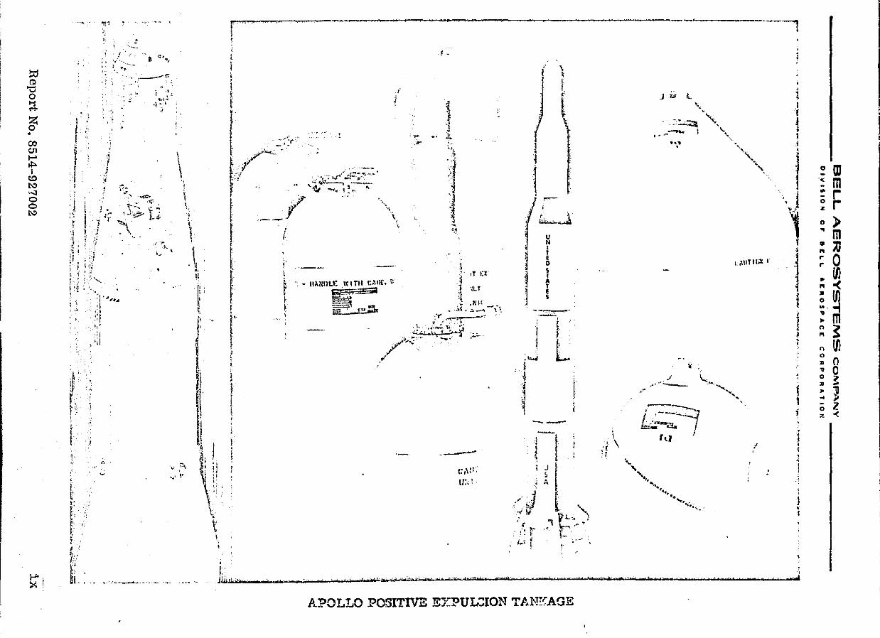
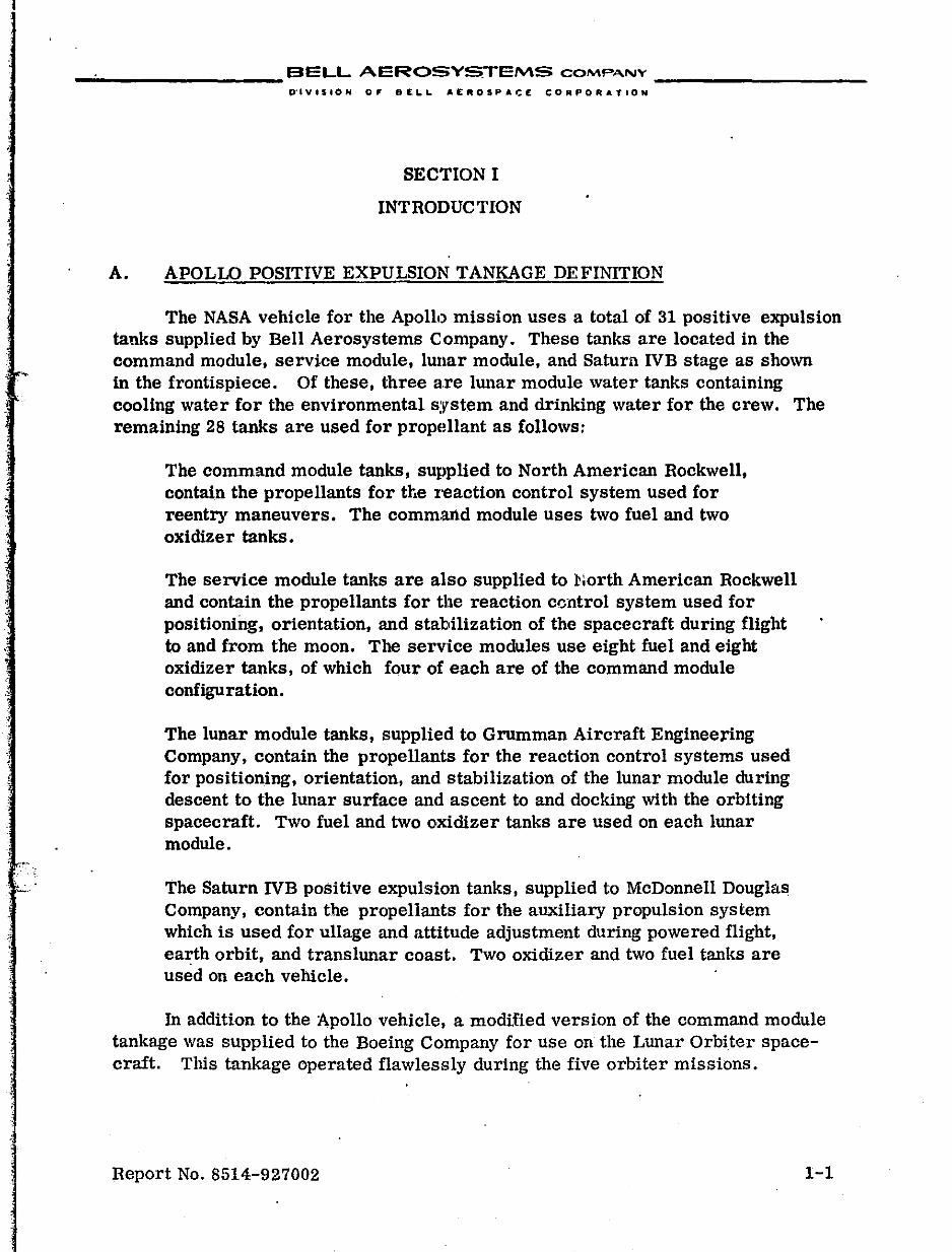
The NASA vehicle for the Apollo mission uses a total of 31 positive expulsion tanks supplied by Bell Aerosystems Company. These tanks are located in the command module, service module, lWlar module, and Saturn IVB stage as shown in the frontispiece. Of these, three are IWlar module water tanks containing cooling water for the environmental system and drinking water for the crew. The remaining 28 tanks are used for propellant as follows:
The command module tanks, supplied to North American Rockwell, contain the propellants for the reaction control system used for reentry maneuvers. The comm.and module uses two fuel and two oxidizer tanks.
The service module tanks are also supplied to :North American Rockwell and contain the propellants for the reaction centrol system used for positioning, orientation, and stabilization of the spacecraft during flight to and from the moon. The service modules use eight fuel and eight oxidizer tanks, of which four of each are of the command module configuration.
The lunar module tanks, supplied to Grumman Aircraft Engineering Company, contain the propellants for the reaction control systems used for positioning, orientation, and stabilization of the lunar module during descent to the lunar surface and ascent to and docking with the orbiting spacecraft. Two fuel and two oxidizer tanks are used on each lunar module.
The Saturn !VB positive expulsion tanks, supplied to McDonnell Douglas Company, contain the propellants for the auxiliary propulSion system which is used for ullage and attitude adjustment during powered flight, earth orbit, and trans lunar coast. Two oxidizer and two fuel tanks are used on each vehicle.
In addition to the Apollo vehicle, a modified version of the command module tankage was supplied to the Boeing Company for use on the Lunar Orbiter spacecraft. This tankage operated flawlessly during the five orbiter missions.
Report No. 8514-927002 1-1
__________ BELL AEROSYSTEMS COMPANY _________ _
DIVISION OF OELL "ERO~PACE CORPORATION
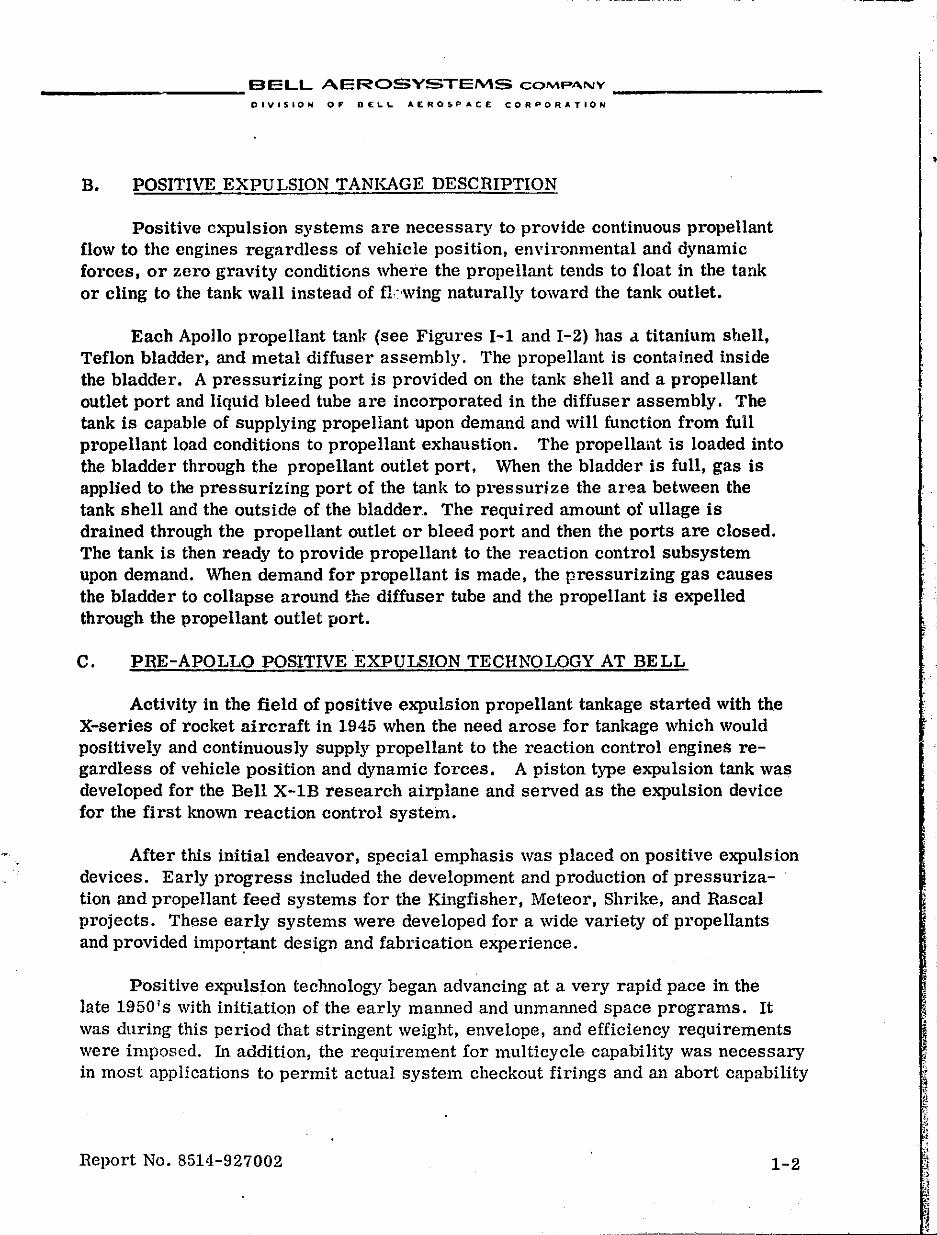
B. POSITIVE EXPULSION TANKAGE DESCRIPTION
Positive c""pulsion systems are necessary to provide continuous propellant flow to the engines regardless of vehicle position, environmental and dynamic forces, or zero gravity conditions where the propellant tends to float in the tank or cling to the tank wall instead of fkwing naturally toward the tanl~ outlet.
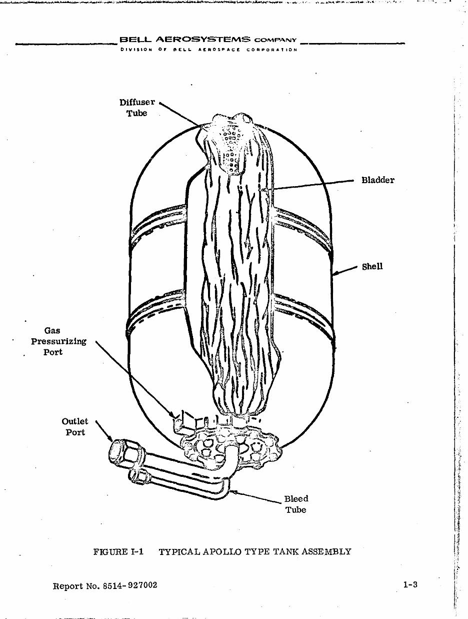
Each Apollo propellant tank (see Figures I-I and 1-2) has a titanium shell, Teflon bladder, and metal diffuser assembly. The propellant is contained inside the bladder. A pressurizing port is provided on the tank shell and a propellant outlet port and liquid bleed tube are incorporated in the diffuser assembly. The tank is capable of supplying propellant upon demand and will function from full propellant load conditions to propellant exhaustion. The propellant is loaded into the bladder through the propellant outlet port. When the bladder is full, gas is applied to the pressurizing port of the tank to pressurize the area between the tank shell and the outside of the bladder. The required amount of ullage is drained through the propellant outlet or bleed port and then the ports are closed. The tank is then ready to provide propellant to the reaction control subsystem upon demand. When demand for propellant is made, the pressurizing gas causes the bladder to collapse around the diffuser tube and the propellant is expelled through the \lropellant outlet port.
C. PRE-APOLLO POSITIVE EXPULSION TECHNOLOGY AT BELL
Activity in the field of positive expulsion propellant tankage started with the X-series of rocket aircraft in 1945 when the need arose for tankage which would positively and continuously supply propellant to the reaction control engines regardless of vehicle position and dynamic forces. A piston type expulsion tank was developed for the Bell X-1B research airplane and served as the expulSion device for the first known reaction control system.
After this initial endeavor, special emphasis was placed on positive expulsion devices. Early progress included the development and production of pressurization and propellant feed systems for the Kingfisher, Meteor, Shrike, and Rascal projects. These early systems were developed for a wide variety of propellants and provided important design and fabrication experience.
Positive expulsion technology began advancing at a very rapid pace in the late 1950's with initiation of the early manned and unmanned space programs. It was during this period that stringent weight, envelope, and efficiency requirements were imposed. In addition, the requirement for multicyc1e capability was necessary in most applications to permit actual system checkout firings and an abort capability
Report No. 8514-927002 1-2
•
" , ~ '1
~ ,. ,
_________ BELL AEROSYSTEMS COMPANY
Gas Pressurizing
Port
Outlet Port
DIVISION 0, OE,",L AEROSPAC;E CORPORATION
Diffuser Tube
Bleed Tube
FIGURE 1-1 TYPICAL APOLLO TYPE TAm\: ASSEMBLY
Bladder
Shell
Report No. 8514- 927002 1-3
-~--~-- .--.-,-,~--- .. ---
i
i I I I
I:
" :
b
_,."
.,.
__
__
__
__
__
_ B
EL
L A
ER
OS
YS
TE
MS
COMPA.~Y _
__
__
__
__
_ _
DIV
IS
IO
N
0 ..
BE
.'-'-A
[R
OS
PA
CE
C
OR
PO
RA
-TIO
".
I , ..
", .... fh~-=:-....,..·:,K/: r:-.' .~ .• ~ • .!."7 ,_
... ..;;: \~".\a,:,:,"7 .3.-""· .. ·
~S$" ~/'
\.,\,-'
.'
F.elJort l'T
O. G
51
4-')2
7:)n
,~, "" ...... ~
...
1 '"",-" .,...""''''~ . tr.l E-,
.Z
't~ i!. 0 p, ">!
"" 0 t.) "
/Xi 0 ,,~
~
.:...
t: ,.:;
~ t ~
:s ~ re 0 ~ P,. 0 ~ 0-1 0 P. <
eo.1
~
~ p ~
f;o,
1-4
. J
__________ SELL AEROSYSTEMS COMPANY _________ _
DIVISION OF' eELL AE"OSPAC£ CORPORATION
prior to the actual mission cycle. This requirement necessitated the use of elastomeric bladders in the Mercury and Centaur hydrogen peroxide control systems and Teflon bladders for the Agena secondary propulsion system.
The pre-Apollo experience,at thi's pOint,separated into two areas: research and study programs for advanced positive expulsion concepts and design, development, and delivery contracts for positive expulsion tanltage for flight vehicles.
1. RESEARCH AND STUDY PROGRAMS
The follOwing is a summary of the major research programs in progress or completed by Bell at the inception of the Apollo program and depicts the background and exp'erience used for the Apollo design :
Shipboard Storage of LiqUid Rocket Propellant Tanks (U.S. Navy) - An experimental investigation was conducted in 1956 for the shipboard storage of liqUid rocket propellant tanks using Teflon and butyl bladders. Propellants were stored in these tanks under shipboard conditions for one year and at the end of this period the propellants were expelled. Experience was acquired in the storage, handling, system deSign, and fabrication problems associated with positive expulsion systems.
Studies For Storage of Propellants in Space Environment (U.S. Air Force) A research and development program was performed to investigate the problems of materials compatibility, serviCing, storing and transferring N204, UDMH, and N2H4 under environmental conditions simulating those encountered in missile and space vehicle use.
Titan IT Storable Propellants (U.S. Air Force) - A storable propellant combination of N204 as the oxidizer and a nominal 50/50 blend of UDMH and N2H4 as the fue) was selected for the Titan II ballistic missile. These propellants were studied and the resultant data on physical properties, materials compatibility, handling, safety, and flammability and eA-plosivity hazards were published in handbook form. Information compiled from industry and government data and from trade literature, was supplemented by laboratory tests conducted at Bell Aerosystems and the U.S. Bureau of Mines.
Research on ,Zero-Gravity Positive EePulsion Techniques (NASA) - This contract was awarded in 19fi1 for the purpose of establishing a compendium of design information on all known methods and advanced ideas for achieving positive expulsion. The program consisted of documenting Bell experience and ideas for ,expulSion techniques and supplementing this information with a literature search and industry-wide survey.
Report No. 8514-927002 1-5
"M "",,'1
__________ BELL AEROSVSTEMS COMPANY _________ _
DIVISION OF OEI,..L "E.ROSPACE. CORPORATION
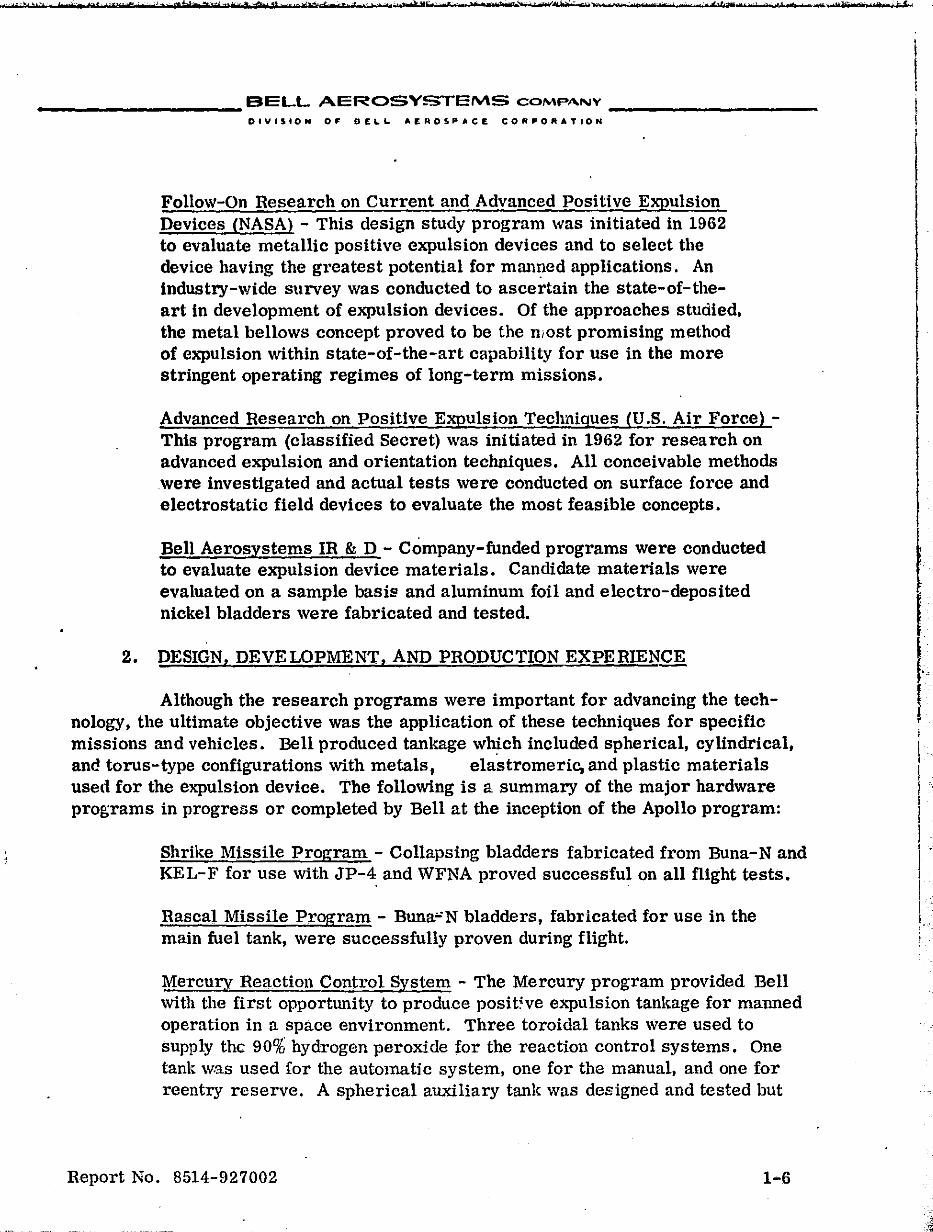
Follow-On Research on Current and Advanced Positive Expulsion Devices (NASA) - This design study program was initiated in 1962 to evaluate metallic positive expulsion devices and to select the device having the greatest potential for mall~ed applications. An industry-wide survey was conducted to ascertain the state-of-theart in development of expulsion devices. Of the approaches studied. the metal bellows concept proved to be the most promising method of expulsion within state-of-the-art capability for use in the more stringent operating regimes of long-term missions.
Advanced Research on Positive Expulsion Techniques (U.S. Air Force) -This program (classified Secret) was initiated in 1962 for research on advanced expulsion and orientation techniques. All conceivable methods were investigated and actual tests were conducted on surface force and electrostatic field devices to evaluate the most feasible concepts.
Bell Aerosystems IR & D - Company-funded programs were conducted to evaluate expulsion device materials. Candidate materials were evaluated on a sample basiE' and aluminum foil and electro-deposited nickel bladders were fabricated and tested.
2. DESIGN, DEVELOPMENT, AND PRODUCTION EXPERIENCE
Although the research programs were important for advancing the technology, the ultimate objective was the application of these techniques for specific miSSions and vehicles. Bell produced tankage w~ch included spherical, cylindrical, and torus-type configurations with metals, elastromeric, and plastic materials used for the expulsion device. The following is a summary of the major hardware programs in progress or completed by Bell at the inception of the Apollo program:
Shrike Missile Program - Collapsing bladders fabricated from Buna-N and KEL-F for use with JP-4. and WFNA proved successful on all flight tests.
Rascal Missile Program - Buna':N bladders, fabricated for use in the main fuel tank, were successfully proven during flight.
Mercury Reaction Control System - The Mercury program provided Bell with the first opportunity to produce posWve expulsion tanl~age for manned operation in a space environment. Three toroidal tanks were used to supply the 90% hydrogen peroxide for the reaction control systems. One tank was used for the automatic system, one for the manual, and one for reentry reserve. A spherical auxiliary tank was designed and tested but
Report No. 8514-927002 1-6
__________ BELL AEROSYSTEMS COMP""'Y _' _________ _
DIVISION 0' BELL AtlilOSPACE CO"PO"ATIO."
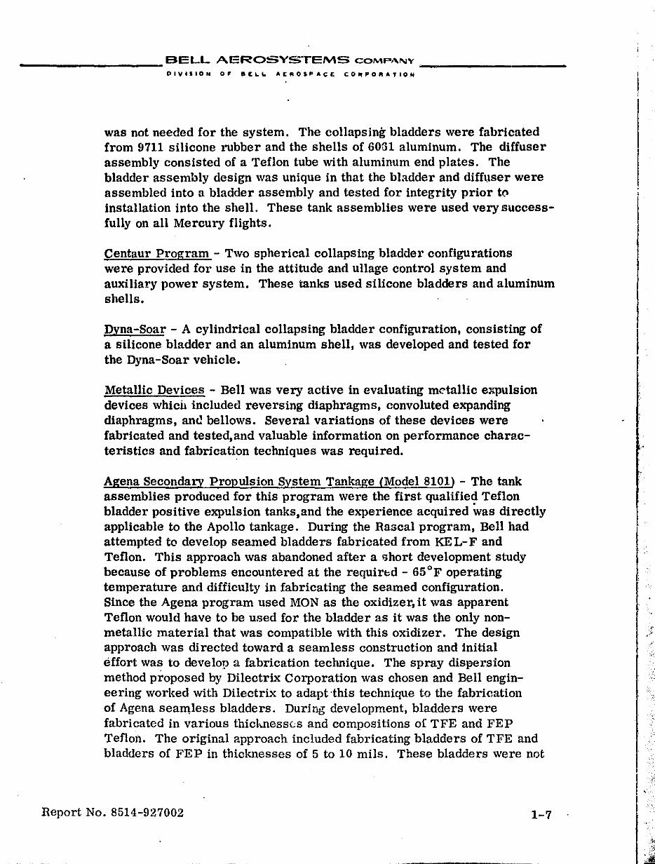
was not needed for the system. The collapsing bladders were fabricated from 9711 silicone rubber and the shells of GOG1 aluminum. The diffuser assembly consisted of a Teflon tube with aluminum end plates. The bladder assembly design was unique in that the bladder and diffuser were assembled into a bladder assembly and tested for integrity prior to installation into the shell. These tank assemblies were used very successfully on all Mercury flights.
centaur Program - Two spherical collapsing bladder configurations were provided for use in the attitude and ullage control system and auxiliary power system. These tanks used silicone bladders and aluminum shells.
Dyna-Soar - A cylindrical collapsing bladder configuration, consisting of a silicone bladder and an aluminum shell, was developed and tested for the Dyna-Soar vehicle.
Metallic Devices - Bell was very active in evaluating metallic e:l..'Pulsion devices which included reversing diaphragms, convoluted expanding diaphragms, ant! bellows. Several variations of these devices were fabricated and tested,and valuable information on performance characteristics and fabrication techniques was required.
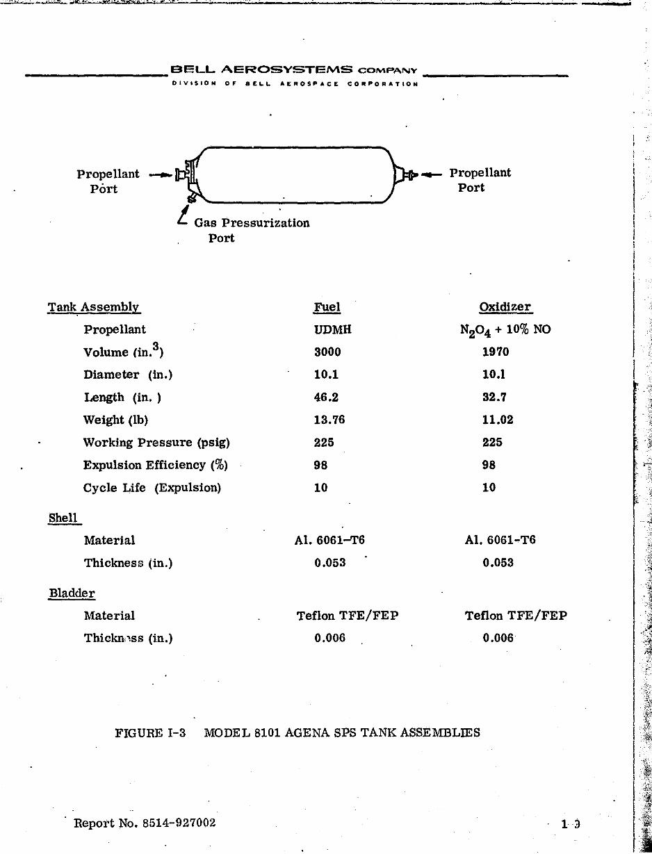
Agena Secondary PropulSion System Tankage (Model 8101) - The tank assemblies produced for this program were the first qualified Teflon bladder positive expulSion tanks,and the experience acquired ,vas directly applicable to the Apollo tankage. During the Rascal program, Bell had attempted to develop seamed bladders fabricated from KE L- F and Teflon. This approach was abandoned after a "hort development study because of problems encountered at the requirt>d - 65°F operating temperature and difficulty in fabricating the seamed configuration. Since the Agena program used MON as the oxidizer, it was apparent Teflon would have to be used for the bladder as it was the only nonmetallic material that was compatible with this oxidizer. The design approach was directed toward a seamless construction and initial effort was to develop a fabrication technique. The spray dispersion method proposed by Dilectrix Corporation was chosen and Bell engineering worked with Dilectrix to adapt 'this technique to the fabrication of Agena seamless bladders. Duril1g development, bladders were fabricated in various thicknesses and compositions 01 TFE and FEP Teflon. The original a.pproach included fabricating bladders of TFE and bladders of FEP in thicknesses of 5 to 10 mils. These bladders were not
Report No. 8514-927002 1-7
"
I '
__________ BELL AEROSYSTEMS COMP""-lV __________ _
DIVISION OF' OELL AEft05PACt:. cOnPORATIOH
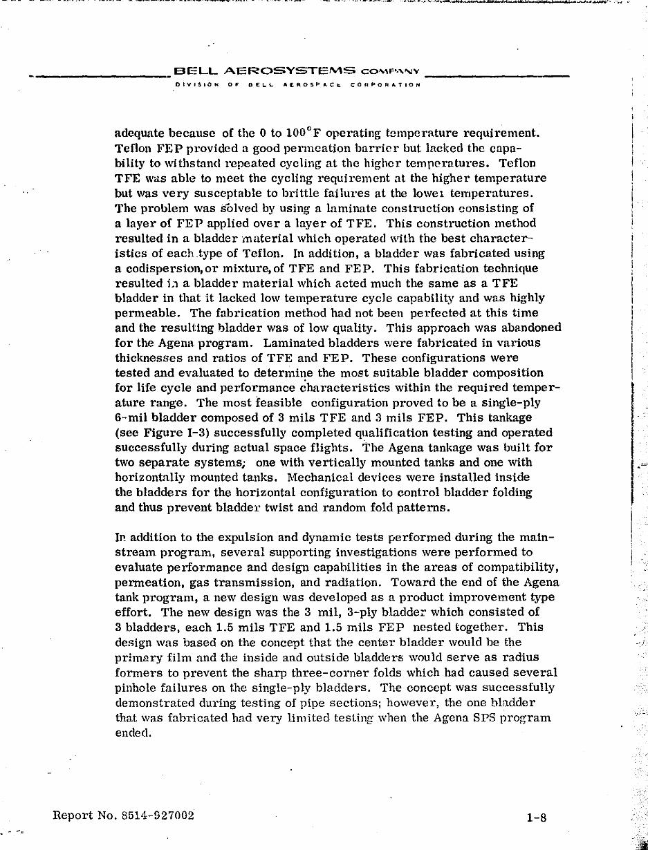
adequate because of the 0 to 100°F operating temperature requirement. Teflon FEP provided a good permeation barrier but lacked the capa-bility to \\ithstand repeated cycling at the highcr temperatures. Teflon TFE was able to meet the cycling requirement at the higher temperature but was very susceptable to brittle failures at the lowel temperatures. The problem was solved by using a laminate construction consisting of a layer of FEP applied over a layer of TFE. This construction method resulted in a bladder material which operated with the best characteristics of each type of Teflon. In addition, a bladder was fabricated using a codispersion, or mixture, of TFE and FE P. This fabrication technique resulted L1 a bladder material which acted much the same as a TFE bladder in that it lacked low temperature cycle capability and was highly permeable. The fabrication method had not been perfected at this time and the resulting 1)ladder was of low quality. This approach was abandoned for the Agena program. Laminated bladders were fabricated in various thicknesses and ratios of TFE and FEP. These configurations were tested and evaluated to determi~e the most suitable bladder compOSition for life cycle and performance characteristics within the required temperature range. The most feasible configuration proved to be a single-ply 6-mil bladder composed of 3 mils TFE and 3 mils FEP. This tankage (see Figure 1-3) successfully completed qualification testing and operated successfully during actual space flights. The Agena tankage was built for two separate systems; one with vertically mounted tanks and one with horizontally mounted tanks. Mechanical devices were installed inside the bladders for the horizontal configuration to control bladder folding and thus prevent bladder twist and random fold patterns.
In addition to the expUlsion and dynamic tests performed during the mainstream program, several supporting investigations were performed to evaluate performance and design capabilities in the areas of compatibility, permeation, gas transmission, and radiation. Toward the end of the Agena tank program, a new design was developed as a product improvement type effort. The new design was the 3 mil, 3-ply bladder' which consisted of 3 bladders, each 1.5 mils TFE and 1.5 mils FEP nested together. This design was based on the concept that the center bladder would be the primary film and the inside and outside bladders would serve as radius formers to prevent the sharp three-corner folds which had caused several pinhole failures on the single-ply bJadders. The concept was successfully demonstrated during testing of pipe sections; however, the one bladder that was fabricated had very limited testing when the Agena SPS program ended.
Report No. 8514-927002 1-8
I I i I
I I I
i
I 1
I I
I
I I
I I
_________ BELL AEROSYSTEMS COMPANY _________ _
DIVISION OF 8Et..L. AEROSPACE CORPORATION
Propellant __ Port
t Gas Pressuri~ation Port
Tank Assembly'
Propellant
Volume (in.3)
Diameter (in.)
Length (in.)
Weight (lb)
Shell
WorkIng Pressure (psig)
Expulsion Efficiency (%)
Cycle Life (Expulsion)
Material
Thickness (in.)
Bladder
Material
Thickn,.1ss (in.)
.f!!!tl UDMH
3000
10.1
46.2
13.76
225
98
10
AI.6061-T6
0.053
Teflon TFE/FEP
0.006
_ Propellant Port
Oxidizer
N204 + 10% NO
1970
10.1
32.7
11.02
225
98
10
AI. 6061-T6
0.053
Teflon TFE/FEP
0.006
FIGURE 1-3 MODEL 8101 AGENA SPS TANK ASSEMBLIES
Report No. 8514-927002 , 13
I,
.
I
.. : '¢, h , 'if) 'N· ',,-., .. . . .
__________ BELL AEROSYSTEMS COMp·" .... V _________ _
OI"ISIO~ OF BELL AEROSPACE CON PO '.TION
SECTION 1I
APOLLO TYPE TANKAGE CONTRACT SUi\ll\1ARillS
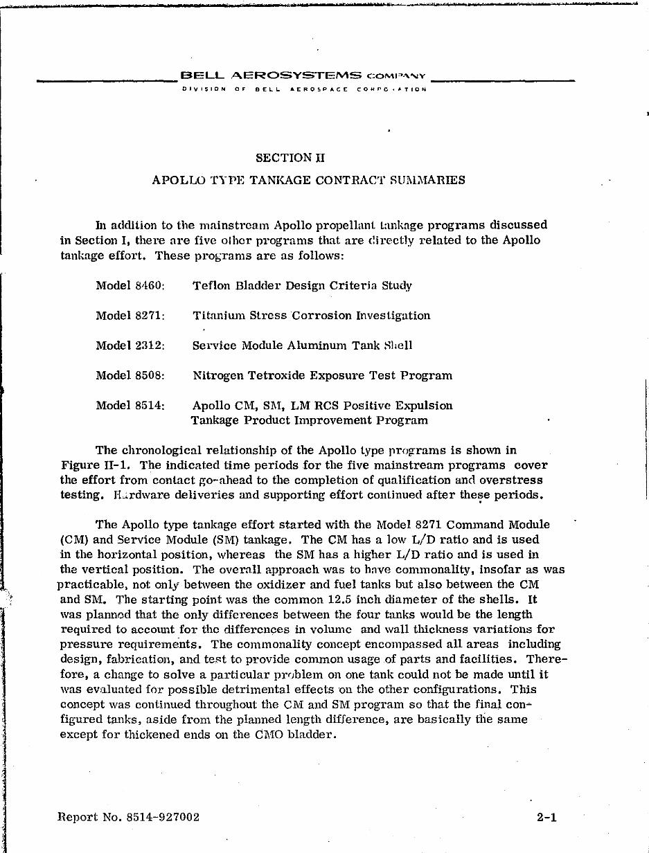
III addition to the mainstrcam Apollo propellant tankage programs discussed in Section I, there are five othcr programs that are directly related to the Apollo tankage effort. These probrams are as follows:
Model 8460:
Model 8271:
Model 2312:
Model 8508:
Model 8514:
Teflon Bladder Design Criteria Study
Titanium Stress Corrosion Investigation
Service Module Aluminum Tank Hhell
Nitrogen Tetroxide Exposure Test Program
Apollo CIVl, S1\1:, LM RCS Positive E}."pulsion Tankage Product Improvement Program
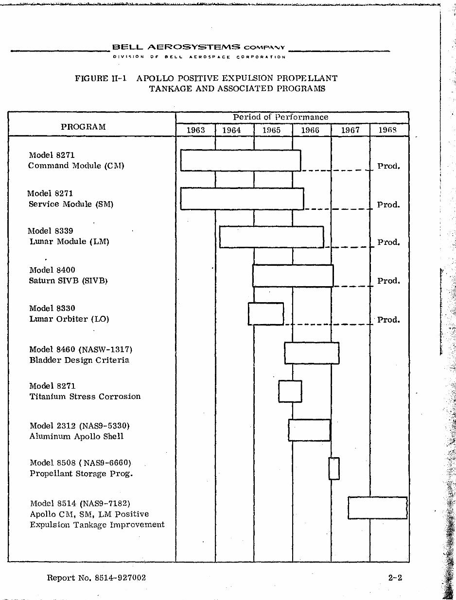
The chronological relationship of the Apollo type prolframs is shown in Figure 11-1. The indicated time periods for the five mainstream programs cover the effort from contact go-ahead to the completion of qualification and overstress testing. ILrdware deliveries and supporting effort continued after the~e periods.
The Apollo type tankage effort started with the Model 8271 Command Module (CM) and Service Module (8M) tankage. The CM has a low L!D ratio and is used in the horizontal position, whereas the 8M has a higher LID ratio and is used in the vertical position. The overall approach was to have commonality, insofar as was practicable, not only between the oxidizer and fuel tanks but also between the CM and 8M. The starting point was the common 12.5 inch diameter of the shells. It was planned that the only differences between the four ttmks would be the length required to accOtUlt for the differences in volume and wall thickness variations for pressure requirements. The commonality concept encompassed all areas including design, fabrication, and test to provide common usage .of parts and facilities. Therefore, a change to solve a particular prr)blem on one tank could not be made until it was evaluated for possible detrimental effects "On the other configurations. This concept was continued throughout the CM and 8M program so that the final con~ figured tanks, aside from the planned length difference, are basically the same except for thickened ends 011 the CMO bladder.
Report No. 8514-927002 2-1
....
,. ·~t"'-'l-=--,*:,,,',¥;'-ert ,'. -., ~:\O). '1:>:UW,f,;~'" hN§"-·tz";" ),- 4¥',,:;-;'L"y' :r-' n t ..... 'b"-t-"d •• ¢'" oi tor. tr r ole; "l
__________ BELL AEROSYSTEMS COMP~"'Y __________ _
DIVISION OF BELl. ... EROSPACE CORPORATION
FIGURE 11-1 APOLLO POSITIVE EXPULSION PROPELLANT TANKAGE AND ASSOCIATED PROGRAMS
Period of Performance PROGRAM 1963 1964 1965 1966
Model 8271
1967
Command Module (C1\!) '----~--__.---..,.-J- - - -- - - - - -I-
Model 8271 Service Module (SM) 1..---...,...---...---.......,,...-1- - - - - - - - -r-
Model 8339
Prod.
Prod.
Lunar Module (LM) 1..---...,...---...----'- - - - - t-Prod.
Model 8400 Saturn SIVB (SIVB)
Model 8330 Lunar Orbiter (LO)
Model 8460 (NASW-1317) Bladder Design Criteria
Model 8271 Titanium Stress Corrosion
Model 2312 (NAS9-5330) Aluminum Apollo Shell
Model 8508 (NAS9-6660) Propellant Storage Prog.
Model 8514 (NAS9-7182) Apollo eM, SM, LM Positive Expulsion Tankage Improvement
Report No. 8514-927002
'r----,---~---- I-Prod.
~---'- ----- ---- .. r-. Prod.
-
2-2
, .. :
,
___________ BELL AEROSYSTEMS CO""lP,,""" __________ _
DIVISIO .. 0'- DELL AEROSP~CE C05lPOR4TIO'1
The Model 8339 Lunar l\1odulc (LM)tanks were designeCl to be common with thc SM tank configuration except for the required additio 1~1 length and the larger diameter outlet tubing required for interface with the system plumbing. This program was instituted before the SM design was finalized and, as a result, was extended concl11l'cntlv with 8M development. The full size single-plv hlurkler dcsign adopted for the SM was applied to LJl.L This design was not com]", I, tely suitable for the LM tar.ks bccause of the larger LID ratio and corresponding hbrlder repositioning problem. A development program waR conducter! to solve the repositioning problem and the solution was attained with a 6 mil single-ply blan(iCr with a diametrally undersized cylindri~: I section. This undersized bladder design is the only basic deviation from the commonality concept established between the LM and SM tankage.
The Model fdOO Saturn SIVB fuel and oxidizer tanks are the same size as the LM oxidizer tank which was used as the basic design. Thr design was modified to the extent that a stainless steel diffuser was used instead of aluminum (no bimetallic joint). Tube fittings were installed on the port tubing and an additional gas port was incorporated at the blind end of the tank.
The Model 8330 Lunar Orbiter (LO) program originally utilized the CM tanks; however, two major modifications were incorporated during the program. The first ·change was the use of a thick-walled shell for the oxidizer tank to retard stress corrosion for the duration of the LO mission. This approach was taken because the stress corrosioil problem had not been solved at the time LO tankage was being delivered. The second major modification was the addition of an aluminum foil laminate in the oxidizer bladder as a permeation barrier against saturation of the oxidizer with pressurizing gas during the mission ..
The titanium/N204 stress corrosion investigation was performed as part of the Model 8271 program. This investigation was started because of a failure of an SMO tank during storage with N20 4. The failure was verified immediately by additional testing of titanium shells with N20 4. The resulting failures emphasized the existence of a compatibility problem not only with the positive expUlsion tanks but also with all types of titanium tankage. The investigation disclosed that stress corrosion occurs if NO is lacking in the N20 4. The problem was eliminated by controlling the amount of nitric oxide in the N20.1,and this "fix" was applied to all programs by adoption of NASA Specification MSCPPD-2.
The l\Iodel 8460 Teflon Bladder DeSign Criteria Program was instituted separately and paralleled the mainstream tankage programs. During the development phases of these programs a wiele variety of bladder failures oc~urred. Since failure morks could not readily be determined, there was a neer1 for a fundamental engineering study of bladder design, operation, and quality control. This program was established to determine design and quality criteria to enable evaluation of the main stream tankage.
Report No. 8514-!l!!7002 2-3
.. '"
.' ~
.------ --------- ---------------------------
E"l.:LL ,AEPC>SYSTEM~ - ';"'-" ' --------- -----,,---o I" I!. 10... l' I') r L L • E R 0 S p .. C eel) A PO R .\
The Modol 8;).;g N,~()4/Titanium Exposure T('st Progr~m was established to supplement thc inlorm~ltio,1 ;l\'fjuired on the Titanium/:~!!O,l stress corrosion progra.1" This test prrgram was r"~ hrnerl to extend confidence in the A\10110 ~radc N20.j lw checking the effects of t"r""p Hlture cycling and sloshing .:I,,'ing a propellant storage period of 30 days,
The Model 2312 ,\:' ":(. Ah:r.1inum Shell Program was Implemented to provide an Apollo type tank shf'll I Lll'.cated ;rom aluminum .10 j (.,lpnhle of withstanding external pressure, The ('<iM' ng thin wall titanium shells are designed for the ,owest possiblr structural \,'('ig'll1 and will :10t withstand externnl preSS1Te. The aluminum tank shells are function:;iiy interchangeable with the 51'11 oxidizer configuration.
The Model 8514 I. polIo C\1:, SM, and LM Positive Expulsion Tankage product Improvement Program. under which this report is being written, is currently in progress with the nhjective o~ improving and upgradin~ the tnnk assemblies in tIlt' areas of per!'o:'lil.ance, re1i:.bility, and mission duration.
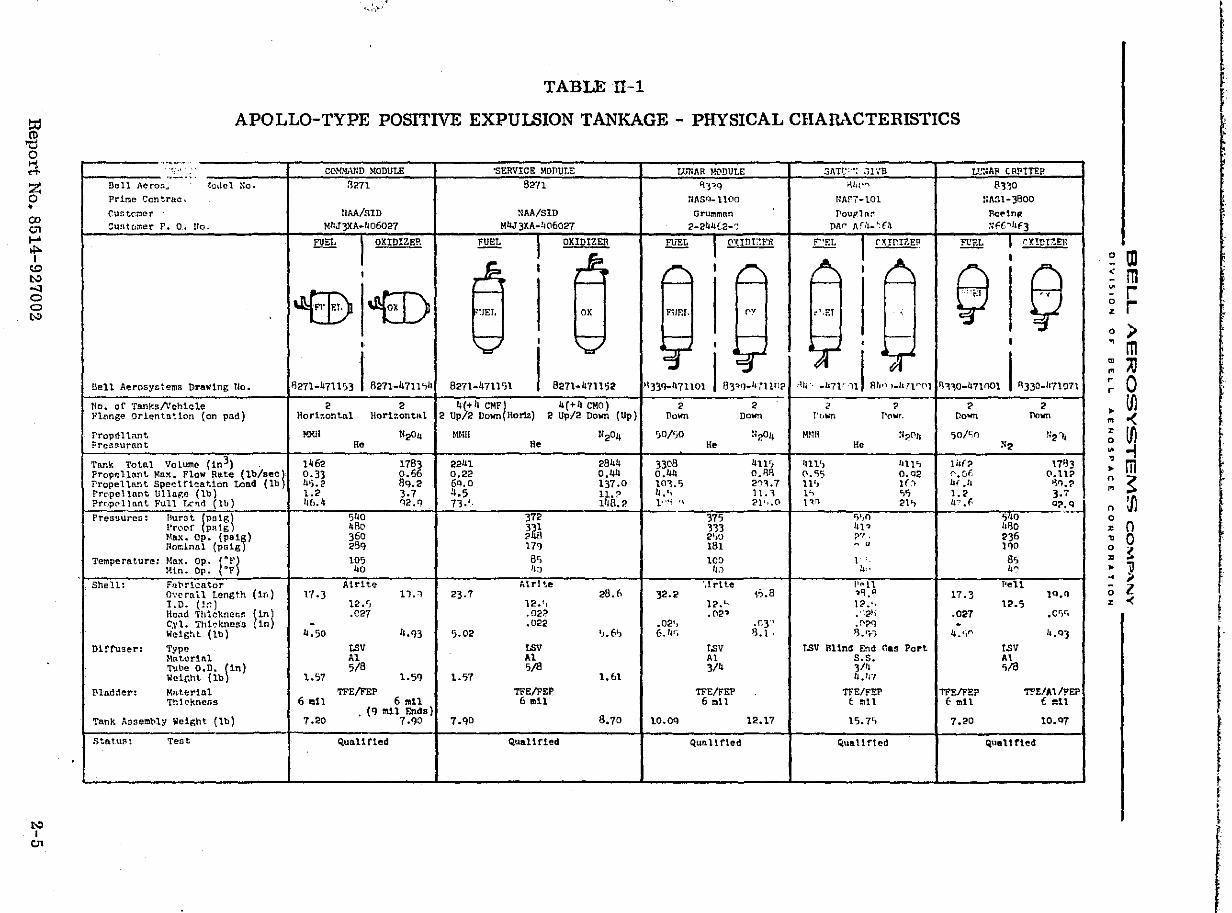
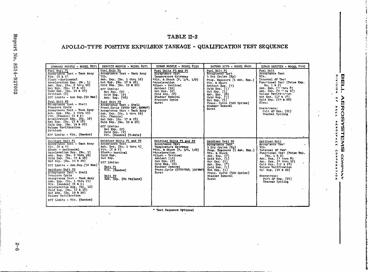
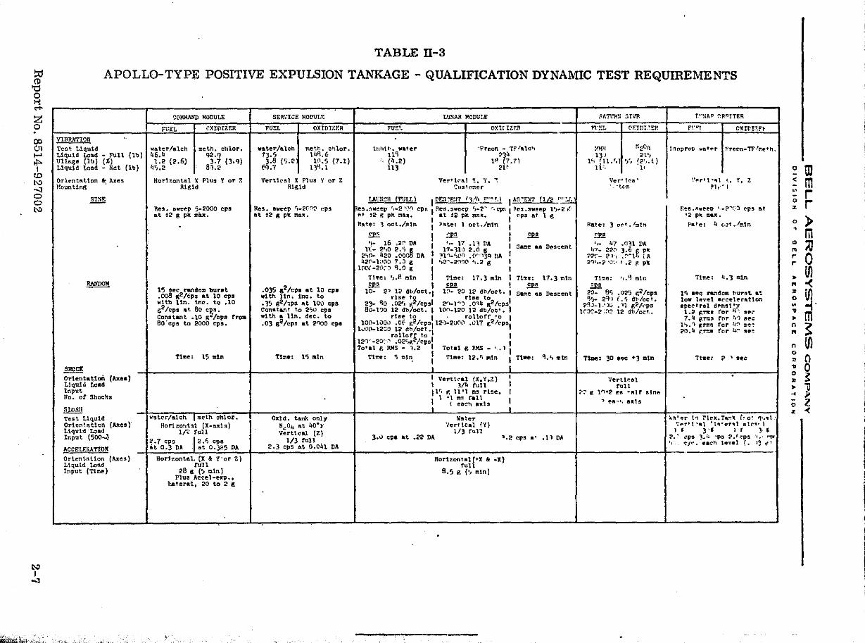
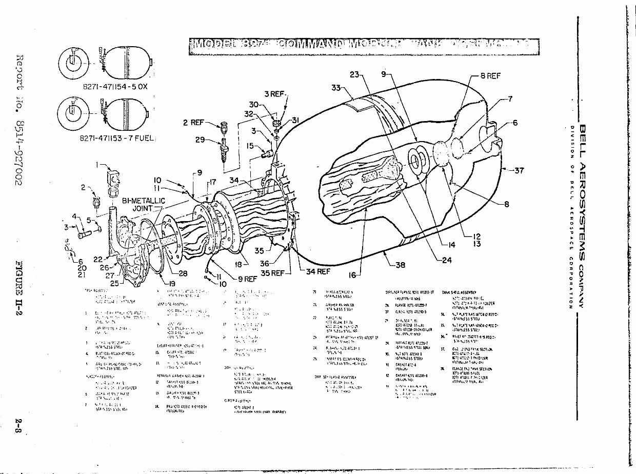
Although the cuncq t of common technology Let\"I"";, tank programs was f1(ihcl'l'd to as much as possiLle. It was necessary to deviate in instances dictated by Itll'lk size and indivlrlunl program specifications. Comparisons of the physical characterwt!cs and operational and tt1St ,'tltjuirements for the five tankage programs is shovm in T:1bl~.;;
II-I, 11-2, 11-3. Exploderl views showing the latest eonfigur.l.tions for the CM, S;,1. L:vr, and SIVB tankage are pre,;t,nl:cd in .... igures TI-2, 11-3, 1I-4, and II·,ri. The confi;.;"Urati(ln~; shown in these viv,\''l are those delivered b) Bell for lise on Lh(l manned Apollo missiol'Js.
-------
i:i!;;,;,
l o :4-~ • co v' .... II:> I
CJ:)
t-:> -'l o o t-:>
t-:> I
en
,:., ... :'
TABLE II-l
APOLLO-TYPE POSITIVE EXPULSION TANKAGE - PHYSICAL CHARACTERISTICS
".--.~ .. . ~--.' ' CCMMt\ND M_ODULE 'SERVICE MOnUr.E LUNAR y'{IDULE SAT!.::-'": :;1 ,,'n Lt!':iAF CRP!TF.R
Dell Aero5 .. l.o\lel No. 3271 6271 ~:pq ~JI('" 8330 Prime Cent-rae, tMSq·ll00 t:Af7-101 NM:.1-)800
Cuzt.Cr.1el" liM/SID "M/SID Grumman l'oupll\!': Fc~1n~
CU!ltC1:r.er P. O. flo. M'IJ3XA-406027 M4J3XA-!W6027 2_2li4[2 ... ~ Mr Ar:~_':[4 ~H:(,'"'''f3
FUEL I OKIDIZEP. !!!§!:. ! OXIDIZER ~ I (I'UnEFiI. .E:.:,g 1 r){!r.I7IE~ Ei& l rX!!l!!.ER
~ I
1 I I
~ e i--i-- '-- f-- f-- '--
~ 'ffi ·~JET. OK FURl. rv r',r:T ,
1 i-- 1 r--- i--
1 r---- r---- • - I
Dell A'!rosystems Drawing t10. 8271-4711'>31 8271-4711'>" 8:?"(1-4nlt;1 I 8271-471152 >I)l<I-lI'fliOl I 03'o-lrrllne 'Uv -"71",1 S'''' ~"""Ol 8~30-471001 18330-,171071
tlo, of Tank.s/l."ehlcle 2 2 4(+1, eMF/ 4(+4 CMO) 2 2 2 e ? 2 Pl~nge orientation (on pad) Horizontal Horhontal 2 Up/2 Down nom) 2 Up/2 Down (Up) Down Down I'town n{'lwr. Pown. IIown
Prop!!llant Won N.c. !>u·m 1l204 'jO/~jO U20J~ w,,7!i :'20r~ 50/'10 ~;2 ,), ?rcssUrnnt He He He He "2
Tanl-:. Toto.l Vo lume (1n 3) , 1462 1783 22111 2844 3308 411'-) 411') lnl', 14(:;> 17q3 Propp.llant. }l:a.~. Flow Rate (lb/8ec~ 0.33 0.66 0.22 0.44 0.44 o.nn (\.'55 0.02 (I.Cof. O.l1? T'ropeltn. ... t Spedf1.'!at,ion Land (lb 4':i.2 8q.2 6Q,O 137.0 101,? 2'H.7 II', H:1 1.1( .11 ~I'l.? Pr{'lpel1nnt Ullage (lb~ 1.2 3.7 4.5 ll.? 4 ' 11.~ '" 'i~ 1.2 ].7 . , ?rcJpc>llnnt Full Lc''\d 111) 116.4 '12 JI 71.', lllO. ? l' .• -~ '1 21 l,.(l 1'0 21,> 4"'.F O?Q
PressureD: Burnt {P!l1g~ 540 372 375 ,)1,0 'j1O l'roof pulg 4Ho ~~ 333 III 7 Id30 Max. Op. (PS1~) 360 2~)O ?" . '36 r:odnal (p!>lg 28q 171 181 o , lQo
Tempera.ture: Ma~. Op. f~F~ 105 Be, 100 1 8'i !Hn. Op. "F 40 1'0 II,) 4· 4'
Shell: rllt>rlca.tor Alrit'! '..I.rl ~e ',1 rt te p"t 1 T<ell O'.'cral1 Length (in) 17·3 11,1 23.7 2B.n 32.2 ,-;.8 .,q,CI 17 .3 lQ.Q
1.D. ('"i 12. r, 12.'1 12. r, 1:? I, 12.5 Hend Thtckncns ~1n~ .027 .O2~ .n27 ."2,1) .027 .CI):-l
C.Y!. Thldmess 1n - .022 .021, ·f:3" .~eo -WelS~lt (lb) ~.50 4.Q3 'j.02 ').6'J 6.IIf', q.l ' '3.';.) 4.'jt"l 1,·Q3
Diffuser: Type UlV UlV ISV T~V 811nd End r..s Port ISV }tnt!!r1al A1 Al Al S.S. A1 'l\lbe D.D. ~in) 5/8 'j/8 3/4 4/1
' 0;/8
Wc1r.ht {lb 1.57 1.5Q 1.57 1.61 .1.., Bladder: Mnter1nl TFE/FEP TFE/FEP 'll'E/FEP 'l'FE/FEP TFEIFEP ~E/A'/FEP
Thickness 6111.11 6 mll 6111.11 6 mll f: !!Ill f mll € !ttl
Tank Agsem~ly Weight {lb} . (q .. n Ends)
8.70 7.20 7.90 7.qo lO.Oq 12.17 15.7r) 7.20 ID.Q7
Statu:;: Test Quallrted Q.uall fled Qunl tfled !;tllatlfted Q.tllil t rted
,"~~L .,*7· . , ,~~' ,~
~ !D ~ m ~ r ~ r o > · m ~ ;lJ ; 0 • Ul '" -< ~ Ul ~ -! : m ~ ~ n o
lfl '" n ~ 0 o ., '" ~ • iI ~ ;. (; Z z -<
I J
l I I ! !
t
~ , ~
!:O (t) '0 o t-1 ,.,. Z o . ex> c:n .... ..,.
1 to ~ -:t o o l:'-'
~ I
0'>
TABLE II-2
APOLLO-TYPE POSITIVE EXPULSION TANKAGE - QUALIFICATION TEST SEQUENCE
. COMll.A!ID ~~ODutE - 1Il0DEL 8271 SERVICE MODULE - MODEL 8271 Lt'NAR MeDtCLE - MODEL 8339 SA'IURtl SIvn - MODEL 8400 LUNAR aR9ITER - ~ODEL g"o I
Fuel UnIt Pl Fuel Unit PI Fuel Units Pl: a."1d p4 Fuel UnH Pt :'eel Unit I Aeceptan~e test - Tank Assy Acceptan~e Test .. Tank Assy Acc~ptnnce 'rest AcceptlUlce Test Acceptance Test nb. (X & ~\ Vlh. Temperature R~tremes 5 Dry Cycle. (N.) Vlb. Slosh - Horlzonts.l Amb. Exp. (No.1 thru 16) ·Vib. & Shock (F. 3/4, 1/') Prop. Exposure {I Amb. Exp.) Ir.ternal ~p Tent Acceleration Exp. (Nt". II 1I0t E.'p. (No. 17 & 18) *Acceleration Vlh. &; Shocl{ Func~lonal Test (Pulse Exp. Amh. Exp. {llo. 2 th"-u 16 Cold Exp. (No. 19 & 20) ·Slosh .. Vertical Arlblent:. Exp. (1) No.1&: 2) lIot Exp. (Uo. 17 &: 18) orr Limits: Ambient (16~ Cold Exp. (1) ,\:th. Exp. f":l thru at Cold Exp. (No. lq & 20) Hot Exp. (.) . Hot Exp. (2 Hot Exp. (1~ k=h. Exp. q ·~ru 1·) Je+.;t!son (2) Cold Exp. f2~ Cold Exp. (2) ""b. Exp. f I Volume Verlrlr~tlon ,
Off Limits - Amb.Exp.(50 Max) Amb. Exp. 4) Bladder Removal Cold Exp. 1 Hot Exp. (17 A:. l~)
Fuel Unit P2 Fuel Unit P2 Pressure Cycle lIot Exp. (1) Cotd Exp. (10 & 20) Burst Press. Cycle (500 Cycles) Slosh
Ac~eptnnce Test - Shell Accept~~ce Test - Shell Bladder Removal I Pressure Cycle Preso .Cycle (2700 NWP • .}:GNP) Durst Overs t.ress! I Acceptrulco Test - Tank Asny A~ceptnnce Test - Tank Assy Full &? Exp. (21) Anb. Exp. (No.1 thru 15) Amb. Exp. (no. 1 thru 16) Thermal CyclIng Vlb. (Ptmdom) eX 5: z) V1b. (Random) Accelernt10n Exp. (No. 16) Hot Exp. (Uo. 17 &: IS) Hot Exp. (flo. 17 &; 18) Cold Exp. (No. 19 & 20) Gold Exp. (No. 19 & 20)
Ofr Limits: Volume Verification Hot Exp. (2) Joettlson Cold Exp. {21
Ofr Llrnl ts - Vlb. (Random) Vib. (Random (Y-Axis)
Oxtrl1:::er Unit PI Oxidlzer Units PI and P2 OxidIzer Un1ts Pl and P2 OxId1zer Unit P2 Ox1~t1zer Uol t Acceptance Test - Tank Assy Acceptn.'1ee Test Accf"ptenc:e fest Acceptance ',est Accep· ence 'res t . Vih. (X & Yl Amb. Exp. (llo. 1 thru 4) Temperature Extremes 5 Dry Cycles (fly) Vlh. Slosh - HorIzontal Vib.(X&Y) • ·VIb. ~ Shock (F, 3/4. 1/2) Prop. Exposure 1 Amb. Exp.) Internal AP Test Acceleration Exp. {No. II Slosh _ Vertical ·Acceleration VI b. &: Shock FUnctional Test. (Pulse ~. Anb. Exp. fNo. 2 thru 16 Cold Exp. ·Slosh - Vertical ""b. Exp. f7l (No.1 .. 2) Cold EXp. No. 17 & IS) Hot Exp. Ambient (16j Cold Ey.!'. 1 Amt. Exp. ~~ thru 6~ Hot Exp. (No. 19 & 20) Off Limits: Hot Exp. {2 Hot. Exp. (l~ Amb. Exp. 0 thru 1 ) Orf Limits - Amb.Exp.(50 Max) Cold Exp. (2) ""b. Exp. f 1 Cold E:lI;p. 17 i: l~) •
UnIt PI Bladder Removal Cold Exo. I Voluf.,e Verlflcatlon Oxlr:tlzer Unit P2 Vlb. (Random) Press.Cyc-le (2700NWP, 300MWP Hot Exp. (1) Hot ExP. (lq & 20) I,~ceptonce Test - Shell !Jurst Press. Cycle (SOD Cycles) Pressure Cycle Unit P2 Bladder Removal Overstress: Acccpt~~ce Test - Tank Ansy Amb. Exp. (To F~lure) Burst Fun AI' Exp. (21) Amb. Exp. (::o. 1 thru 15) Themal CycUng Vib. (Randam) (x & Z) Ac~eleratlon Exp. (No. 16) Cold Exp. (No. 17 & 16) Bot Exp. (rIo. 19 tc 20) Vol~e Verification
Off Limits - Vlb. (Random)
- -- - _ .... _--_ ... _._--
• Test Se~uenee Optional
;:t,H; .... ~'·.M.'~.c.~·;:.t'\C.~.'3}~~<~'.,.7·iZIi·.h,\4U .... :L.,.d)l ........... ,JXA A. ilk « %£. i., ..• ----- --
la;..., ..
~ OJ ~ m ~ r ~ r o » ~ m : ;U r 0 ,. ,
• 00 '" -< ~ 00 ~ -I : m ~ ~ n 00 ~ 0 • 0 ~ ~ • il ... i> ;; l z -<
! ~ 1-'
t
I,
•
I I t
!:O CD '0 o I-j ..... z o 0:> 01 I-'
""" I <:0 l'-' ""1 o o l'-'
l'-' I
""1
TABLE IT-3
APOLLO-TYPE POSITIVE EXPULSION TANKAGE - QUALIFICATION DYNAMIC TEST REQUIREMENTS
V1.flP.A'l"IOfl
Tent L!.quld Liqu1d Lo~d .. Full (Ib) un ... (lb) (~) Liquid tolld - I,et llb)
Or!t.f'ntat\on • J\xes ncunt.1ns .
.ill!
~
~ Orlent.~lon (Axe.) tlquld Load Input No. or Shoc:1I:s
~ Test tlq:lld QTlen~atlcn (Axel) Liquid LozuJ Ir.put (500-1
ACCELF.l\ATlOK
Orlent~tlon (AKe9) L1qu1d wild Input (Tll!le)
';OMMAND MODULE
FUEL CXIDIZER
water-/alch ~6.~ 1.2 (2.6)
11'':..2
,meth. ehlor. q2.1) l.7 (J.q)
81.2
Hor1~ontal X PIU3 Y or r. Rigid
Res. sweep 5-2000 epa at !2 B pk mu.
1~ lec2
randa= bUrst .008 S Ic:p~ at 10 epa with Un. inc. to .10 g2/cps at BO c~s. Constant .\0 g /cps from Bo'cpa to 2000 eps.
TIlle: 15 .1n
\0'11 ter/a.l eh I n:ethchl 01'.
Itorl z:o!,tlll (X-!Ut1 s) 1/< rull
2.7 ep!I 12,Il cps .t 0.3 DA at O.3~5 DA
Ho""-:.on1.&1. (X " 'i'or Z) rull
28 g (') 1':I.1n) Plus Aeeel .. exp."
lateral, 20 to 2 «
I
SEP::ICE MOt!UU:
FUEL
water/alch 13.'
3.8 ('';.2 fO:1
OXIDII.ER
troett-.• ct:lor. 11~F\. E 10.5 (7.1)
13-Q .l
VertiC'sl X Plus Y or Z R1g1d
Res. eveep ,_2r,fjC' cps at !2 ,; pk ma"!!:.
.0)5 «2/cPI .. t 10 epa wlth lin. inc. to .3S g2/:ps at 100 cps Constant to 2?O cps with. lin. dee. to ,0) g2/cpo at 2~OO epi
TI~e: 1') aln
Oxld. tank only N:.:C", Ilt 40"1-" VerUcal (Z)
l/l rull 2.3 cp~ at 0.01,1. Ill.
FUEt
1n:l\l'>. water ll9 (11.2) ll3
LUNAR ~CDULE
onr IZF.fI
>Freon .. TF'/lI;lc" ?34
1P (7.7\ 2H
Vert t<-Il1 'to Y. "': ':ulI1olller
unl::" (FULL 1 I tYE.T':t:IT 'lltl ::-~ .. '. \ I AS"'!:.":'" (1/2 t",":.r~ ); es .!1weep ',_2 '"_'n cps I fles .:Jweep 'iM2~ ,r,t'p(\ I Pes .sweep 1')_2.C fit :!2 g pk !'Ill.. I at. ~2 pit r.m.. I cps at" 1 S Rate: ,oet./r.:tn I ~l'Ite: 1 oet./e1n ,
£2E. I !:Err : £2! '.- 16 ,2f' DA I ',- 17 .11 DA I'
H- 2',0 2.'l 17-"11\1 2.0 g .,a:M! .. s Dencent 2 1io- "20 .oo~5 DA. I :al"1_'lP'l .<"\'1)9 DA I "20-1;100 7.J g I ·'O ..... _2~'n(\ ',.2 g 1
lC\(\(-2f1;J q.o g I I II!!!e: ',.8 l!'Iin I Tillie: 17.3 ",In I Ti:ne: 11.3 ~tn !e I .£2! £P.!
10- 2' 12 ~h/oet'l 1~- 20 12 dh/oct. , Sar.-,e '" Descent rbe to rtse to I
2)- '10 .02', F.~/epsl 2f}_1 .... ., .0":1.4 g2/cps 80 .. 1')0 12 db/oct. I \0(1-1::'0 12 db/oc'. I
rhue to I " rollorr'o I 100 .. 100,1 .elf g2/cPsI12i)..2;J0(\ .0\7 g2/C'Psl
11.;'00-12'J0 12 dh/OC"t., rolloff to ,
121'" -20":",""1 .02r)g2/C'PD1 , I TO'al Po RM5 .. 1.2 I Tetal g RKS .. ',.1 I
Ti!!le: 1j al~ : Tillie: 12.1i IItn I TIft! ~.r, !I'Iln
I I I V@rtt~al (J.r.Z) 1 lib full prj F': \1'1 1115 riDe.
1 .\ I!l:I rall I (eaC'~1 ax15
.~
3.v epa at .22 DA
\litter Vert \eal (Y)
1/3 rull
, I I I
-.l
'.2 cps a' .n DA
HorlzontalC.X & .X) full
8.5 g (IJ ",tn)
~An'R~' !;I\11\
n:EL I N:ID1'.~ER
:IMH 13J
\'" '11. ".11 1 i~,
~:201' 2t')
t}~J !2'J. t}
" Ver" lea'
-te::;
~ate! ) ct"t. '::lin
= ',- 47 .n31 VA 1,"' .. 22(' ).6 f. 1'1!.
??fM 21, .~"'1~ ill. 2~'.-2 "(""' I .2 ~ pll
Tl::1e: > •• J} !!lin
.=£!!. 20_ e~ .025 R2/eps 'J')- 2~'1 (. 'i dl>/ec t.
2~J-l,')O .'1 g2kps 1,:-:>C-2 ~~~ 12 db/oct..
TiDe: )0 lee: +) min
;>;." i,
Vert leU rull
1~"2 m~ ~"lf sine , e"~'l a.ls
r.'";'l\fI "'RntTER
Ft't.'"T CX%'tl~n
!!lClpror; ",,!'th'r l?'ret'n_TF!~e'h.
~·"rtt'.l (. y. Z ~It"' I
Flee. ~"ef'~ ',_?":,1 t'ps Ilt -2 pit ea •• Pille: b ~~t./etn
T1tte: Lt.) !!lIn
11j lee nL~~~ ~u~st at low II1t\'~l aet'eterlltlo.'1 .pectrsl d~nft1~y I.~ ~"I::I ror ~-: st'r' 7./' f!rtlS fnr !.'1 !!lee
1'-1.'1,1'%:': fer ll~ se~ .,0.1.i r.r.:1!1 for l~:, "I!~
T1m!!: ?' Sec
l,"'~r 10""1 i'leJl.r~" ('0· fr."" ':,.r·t ~,,\ 'll!;'er,l II t(,lP l 1J 3'1 )'r l'
?" "ps )." "p!l. ".I ~ps 'I.' tV t, ,,:yr-. each lll!vel (. l~ ~\
.. ;/
~ OJ ~ m ::: i ~ i
? ) m : ;iJ ~ 0 • (j) '" -( ~ Ul ~ -j' : m ~ ~ n III 0
" 0 ~ 0 ~ ~ • U .. » (; Z z -<
~.,
.... J
Q '0 o >3 ci'
}. -' .~
o •
@·.'"m"l." .. f ' :;r, • ~ - _. -' : '
, '
8271-471154 - 5 OX
0.t\ Krlr'\
~--'''- '.'--- .~-~ ... -c"':!" • 1,; :~. - .... ,. ,. ".1 ' "':1IVICC,'~1 '; ." ";.'"",., lo" _, 1;., ,._ - L. CO '-, Co f \'" ~~
--.---.--...... ---.-
7
cc Vi f-' .r.::t
~--uj 2REF~
8271-471153 - 7 FUEL ~
'-0 rJ -.J o o r0
t:.j
S ~ l'i-j
If I:\?
~ I
():)
27"-' 25.1
'1'.. :'~~t·.,;.
• " _~ - ~i
',:i ~';.:-l: '!"I.'~;>
(~ - t .t" I" ~.' .; 'I J~ I." -, -'l. ","',. ',1., ~:~ ,' •.
'·:t. ',' ". .:.;~. 'i '.': ' : .... ,
j'.'
• .-,:, ·t \': ~ ,I' _,'~ t~·"·· .. ns }·f~.,
ol e.t' ::II·~njll·r,~[C~, .,',t'" ,,'.
,',~~ i~ ':",~-~':I!: ':'! ~If,~. "~I· . .t\~ ~~U~ jJ7,
•• ~:: f ~ lH"'~I'
" , .: .. ;, .. .:.; -l , ;', ,1',1 I:';I({~
,':.~ • .', ': '.'\ y rilJ~ ,>'~ '"L;.' .!t '
"," :.t.::', I )1~"oJ~~ }\!lI~ll
-'U~~';,';:!if..::",",;if.<!~;-£:~;- 1!.\,;I-.j,J~~:tY"':i!i:>cY;,:;':': L ;~,:;,"~T~',;.\ .,7·';\i.,
"i ,". : ; .. ~.~ ·,.h~ .... f. '.:
\~\1 :"..!. ~~~l'·':~, • :;; !11,,' .'! .~ •.
. '. , ;'1
~. ., ... i',' ~:j :'1,3,,, ' . ':;1':,1.,: Ii .! .::;. • 1'1",'110
llfill ~tl~l"!~. I~';':;: :.;-) ,. II
(.:,I t '~". ,:"m; -'llI"\ '.;,
, .. '.Il·~I .. \;-~ -'1.\- '.,.
~[1:;I·.I~ ,~.:.~.~~ 'i'/; :.:1;: J.
11
Il
·,"'Vjl·~!I-:I.c,.to..)
,11'.(1.101
i .... ~I~~ ';11111;:"'1,) ,~_ ':'" ',' 1(1.1 .~-
it I't,~~'i\ 411\1; !'l~IO'fJl "IIIU".1I1t
.~-,~;j.c, ... \,~, . -."~ .,. ,~ ..
,
9 REF 35 REF
., . .-!", .:.
," ;- ~ !.
.:- .:' . - , ,
11 ;.' ';: ;;: I - "'~:
" ,~, :,.!. '~ , - 'r ~
~.. . .:.).... ..:,:":" "'1-', -"
~I" ',c ':'l'!','~.'
~; ') 1'1.,.., ~. 'to ,;,', : .. ~. ,- il '"'tlt.'l'I ~I~I', ,"~ \'111 MI, -\1, '.'J', '\\"~I. ~.~- • ..t '\ .,IU\le.\ I( 011,. 1.\1(";01,':1: \.I!t u:;:'.
t;;.·."l'1!·.·1~t
';'1 ::n~1 I ,',\.r"~o~~ \TUI /litl FI'''''fI
~
" "
" :.:,
"
16
'" ;,1:. t!:lJ:I~ ~ '~'ll ... n~ ~!1I.'
~'."\~i t.' ..,.:u ~.~ \,1~~ nil'
~.H;· ~ '~:I ':':,1'0( )1 It ,:.'; ~";1~ ~~~';;.;'1 ,~~I'· .. hJ ~·il .. 0.:: ~I'l"J" l( II"",. ~:'ll :n:-J" l1 ,,t, ':i', .,' .. It: '., !I_I ... • ... ~.a-~::.I· I '1Il~'" ',£
'\M" "'S I:.'~I., ~f';:I. ~·.:.' ... h' ~!!t. "\.hOI,,
~IH i!~ 11~"1"- :'~~".·all
,,..: J~, !' ! I" I. ~. " .:, ::~\ : ",,;,:1" .:.' ',',,, ',' ":,,,1,
~IH~\[P f\.\!;,.t 8!lIllllJHf
l.tU',·I"I~ ~l ,. Jt>\.\ct WI·!.!!:'!'!"
" [(!.}-.. \:rJ,amH
, 'H .. \!. \!: ~"I-:;I:'1' 1l.~1l !!2n-UJ:J!·:iOl.'O'~ .,1, .. '1' ... ·$.":1'
~. IIn,,,~ r:n :r::2:-1 'S'W'!H~ ~1.U lU&l1
"'- "~:!:11 :JI~H '\""~\~ STUll
" c."~o.it ,:.~., ftth.J",i
"- (;"'\Ill \!11 .t1~·1 'IU.~1'\ 11(.
" " .... " ,"i,"""1 ' . Ill ..... , " ' •• .: l.~' ... "J':I' • "'. '
U."«.lo>t:U ISU',II!I.'f'
"-
" .... lI.
,.
!>o.:':·':ill'''' 'II' t. ..~~: ":-:-H· t] ". 103I;£.1I iT!'''\I~\\ lTUl-t.l
.. ~, • ..... t ""S ~~~. a r!'J-:' ,~,(!'\,u:s~ 5'Uu
,~: pt. ... {"~ ~:(.·l'!C:' .{-!Al'>I55 i1.t~,
ttl.,!' \1~ :r'..t"P-t'UtQJ . S'"·".iS<' ~'["
(.J _~ to.j!f"~ stn:.,)\, !:11·.t.·lt~·1~~U "'l·l.·!~!.··1 "'U)ltill: 111"'.",~'!.1 ~.t.A~-:'1
f~"~[~"': ~.I"I. S(CfI~ U~I,!·t.m·~Jl-!l ~IJ-~:~ll r). ';11l~ .nh'\I,\1 IIta, r.,
,,: lie: __ ii .; ~ ~---------
.:.,;r.
--37
8
~ In ~ m ~ r ~ r o > ~ m ~ ill ~ 0 • Ul '" -< ~ Ul " -I : m ~ ~ n Ul ~ n ~ 0 o ., ~ ~
• iJ .. iI ;; l z 0(
~
t
I f (
•
~~ .-v (I)
'0 o J-' • IT
~" ~
o •
cc \J1 I-' +0. I
\0 i\) -.J o o i\)
l'l:j
S c:: !.J.1 l~j
9 t.:)
NI I ~
, .• f" • -/'" ",," , .. C" ' '~"iJ..'1 ~'" ~t:£
w-~ IIIIi ~ •• .,! - .. - w' .'., ---'1_
-,-" -@iffy @ . 8271-471151-11.-13 -II -13
tA'., .l,S5['::. y
~'::·':'.JjJ·ll. -Il r *H ~~;. -~:. ,:.: -II .• n (.,r:.! ':£'1
c. ~~ .; £ l5 W.'~l' !. '; ·41;(1701 ~: '.', ... ~, •. ·t~.(.'. I,!,. ST~: .. l!.\-S ~·H .• vt:",> c .... J,SSl',I'!;. 'f 7t.u}( '\n ~'.,
1 Ifi('_,',I~f \'S xw.~ 'ST~!"IUS S'Ul'
( ~w ):1I·UlJa·jIlQ ~lQ'DI ,Tj·A'.I'.~·'
~_ ~··J;,t{:""-~·I.!;fJ(.·tOilt011 \'lr ••. t!~ ,'tl~ 'U),
!~'~o'[1! ~H['/~, 1
·;m'!il,;~·B ~:;H
~t:: !ll:',; IStj\IJIZER
,'1".":01'-1 v~ :-.l<I5Ll~ ~'!." . .I ~\ ,'11 .. •
.. • , ___ '1 !;;<;.-l I
'~!~I",l~~ S'UI. j.t1j
2
bh:r~:i! .P:!~II ;_{:..;), \ttl\tr~:. ~'H~ or...!·
·.f" ,'\1 '~~£ni.f
:~Ij !ill?l ~ I !i '1.'~ Jo I..:n·!71::t /J' ~l"fl>'l~EfJD'
;. .1\1,t\!
~n'''Im'H' tt em-:I:I,!·:, Ci~ 1~IltP "{hit. !fr,
f'11111 nt~I·.rJ!S lIm·llll1l·1
10. (fl"1~ \:l11 4/Ull J "n.;,'. '!I.
II, 1,r./"'~I .. ~un·41ml-5 '·U:m.III'
m'I·.!"1~\5~~ WJ·4111U')
it 1·~~ •. !I·,m-:·I~·l .m.J, 'II
U ,"l~'H ~m :::1;"0. I ,AI' ','1'. '.' 'I.~I I ...
'I. ,,1,),;1: UH'~'I';-'1l\,iO' ':I'lrJl,'II,
I~. BC.' !.:11·~'1I1J I'~ -to C 1~·.I!\IfH nt'}:i
16. ~,.r.:~I~
ml ~I:!," Hdl ~;I C:.:\,:c'l!Jllr~ .1(1 .. 1;',11[.1111>1
n. Vl\.', IhUIIIH 'oiL! ·,'1;' \\ 1'Io>t1'
I!. P~) 0,:>;1 !I!,"~l I .Ilfw\ 'lUli'"
I'. !;~~'-II'im mm I ~'r;II;" If[,
:llIfi,~rTj: AS~f~.,p,~-
tI:'l: Jl;~'+lil.'lt &?71·.tml l l'lII)IDIZ[R .5T(I"II~~ ~lUl }J1. A.U.\lIrtl""RI, ~'~II,1f ~~ \lIllto[lI(IJ11. tJ\ltl1kO\'l ~IIU ~,lJ,
(tAMP A\~I'.'~L I'
... ~'j ~;lm lo-mlll .. ;"/1 ~1Il~j ,'I'U
'.Itll·'''·~t ~IUI t;tAIJ. PIA~IICI
ro. sc~t.\ ~1]"II)JH IS!l,-WoSS SlUl!
lI. ~"'~t-Ill o\\"'IIOCI~ 1~·.r.I·.,I'I.~ 'HUI
n. 8.(!lt'l,U !27: .ttl1U·IHLI .. ~;I·;j;.'lnl O~I:l'nJi
'~!"'''\[~S''I(H !.IT.
U SP~U~ !C1i-ot1lZt&-1 I!II,(I".1I£_ .. gliAl"!,> '\~'lf",tl ~m-'1I='DH' 1111 '.11\ .,', :>)I',i·16. ... B. !>HlV'; -m·mm-, .1:II"~, ';h ... 1';~Ht '.'~ j~.lU'I'~ ~WDI • .,I,tl\t.{'h ~Iih I!t~ltC)ILI
DIIIU511! FI f.VllI~){~\;I'f
r.'11 4W':1 If 1111:1 Ll:il :;1;:1 : .. .l\!lHIfIl '''!t~,\L''''.I~1I
DIII1·~I"lL"'.I,1 ~m "TIm-U '~I~_'·"'.'·,\~11
9REF
1:' nAM:£ Ull .. rt.·~H
a n5t\ .. !2U·UlZ):·)
:'1 DII' il:: I. e£
!m~:!")I·lH.11 !\Zit :r'.~~·!\J'ltOI1U ''-< ... '.·1 ..... ·''"1'
". '\III\,.~;t·'lI~·' .srA .... tt 50S 5JtlllOoll.,
n. ,",II ~11 n!l..'\,~1 IStAIP.1H~ 'jiTUU
11, "l~t.{1 .-: • ,'U.t1I.,
IJ. r .... ~ .. 1T ~n mMS--1 tt(Il(lo"m·
J..I. •• , .... , r ~I· .... "'''I '. U. ~l I '.1, ._ I :,:. L" I' ','1 ',I .... ",', . I~
'. I ,.; '.' .' • ".'I;I~ " ... " "",
~------ .', ---,--- --~.:-.--~--.. ;:;- - _ .. --._--
:~,- .,,'~ .:~~., ~."
~-' ··i~"~.fl~~:j1: -....
'AA~ SitU ASR ... !tY l'm-.lll(l~') ;tLU ~71 :~l~'t 11 ;'I(I:;I;[F .nl&'\lI.:\I ll&l1l'lVl
". .. ... 1 PlAlI ""'S e41't"lI1fQll' ISTlI\LHS snrll
Jl. tol.:':tI.,I:rt\ASw.c.,,~O'"
lS''''I-''J.SS \11111 J1. RhO"', :o::.:!:lJ-'!>" !Pf0':,!'
15'A11'IlfSS snltl
)t. cumo 1' .. " ....... S(CTlCIIi !Z'n"rnJi-1 .~t!IPlL,l ., .... .:0,.,
It etn ... :!? ·tV \tU'I:JIIi I:;, t:l"~ " '. ~iI trill. 1";-'I~I:tl: .1I'l..,!.\\I<H.-':I'
e f:''''''-·I'~ "'.~ "{'llf'1\ ~·I :.,'\1' ' .! , 'l"~ '.' ' --.11 .: •.
,
·3B
•
~ Cl ~ m ~ r ~ r o :> ~ m : ;U ~ 0 • if) m -< ~ Ul ~ -I = m ~ ~ , if) o • • , • • • , •
n o ~ iI , l «
, i
t
I :1
........ ""' ... ____ .... " ... _ ... ~ ......... _ ..... "M ...... ~
.. · ... _ .............. .-'"'' "'M"~
ri,i. .'.>
,' '." •• -...
_W
..
W' _
__
_ ·_
." ",," ",,"
, ,_
"
__
•
..
_ ••
__
._
•• _
__
•
. • t
··
,,;,'t' _
__
'1
"!
• h
' '
t.
'1
)
' .... ....4
__
__
__
__
__
_ B
EL
L A
ER
OS
YS
TE
MS
C
QM
P .... N
y _
__
__
__
__
_ _
. " , ., ~'
rr
; a n ,"!.:r,
'r-::' r.o '1 I i I I I , 4 l l , j , I I j ! .
_ ....... .i
\j"
w
n: LO
OlC
il , , 'r-"
1-',
..!..(\J 0
0
Oll/I
S,O
N
OF
' O
EL
L.
A£
HO
!'P
AC
(
CO
RP
OR
.TIO
"
FI~URE T
I-4
.' ., ~ , " "
.
snUB
, :;.: ,
.;
.'
'" :::
~
~
,-.::. £:
«
;:j
~. -, .,..
__ 3 i
~.~.
-. ;; i
_
:i
2-10
::0 Q '0 o I-j ... ~ . 00 c.n ~
"'" I ~ t>:> --'l o o N
~ o ~i M' ..... 'i': c:,"1 '
l'f .... ....
--0R?)' \\2./ - r----'--!- OXIDiZER 1 }i!t.,,~v-~-----~-
~ .-.",,1,;· ".' ":)' ~~, _.-" . .,,,,, -- ." --....... _._. . .' .,', "..f""... --~
" I ./ a)I' ---'" " . ., r:'.' . <. ~ '" I ,', ". ---.. .. . , ,. .- ~ ... , "",--1 _ . . 'II c--··----~ .,' ,. :' ".,";, ~""."_"'_~_ . l,\!l"
I • -. CO ,e, '--!II.. .-"
I1II1 J' r~c."~r ..... ~ 'tu;;.r-\ '
~.,.,.Y 31 REF ",// ) / (GAS INLET"" ~"'~\~:::z';/ 30" ~29 , \ .. 'v'd" ,- --rJi! ,,2 REF ~'-l. -"1~:~;~ /0.o'fTh,r. ? REF 13 ~V )PORT) ~ U' . ____ -./'" <:n I ~. / '--9 . t",( , \ )..).-."",.......-1i'\
2 i?4
..J r 17 14'-.\~['0 fl5;:J-fRf. ':=~"~ \ _jc~"'c~r1?~ ~'-\\ 1 0-- __ ~. "<;(').. 'e:.JiE1o~ f"~" . > ". ,y-------- -:;Ji "'lr;,l\f.F \ 'r,\;: _. --EI- '" );' '" r r;v c," " . .~~.x - - r ,'" ' \ .j).1. I LR~ - \:' .. ~LJ .::\ 1'< ~J: :\\ \~~, . -::~-: .\ 1,.(- ~ .... ::;'- ': -- -" . '\ I ~ .. ,---I" ".,.". .,," _~,\," \\ "...0<') , '--. , .. -" -r·.'- ~I I J PORT A
"<-- c.L ~~"~"':;'-/Al\ iy\ :~..... ...c"-/-" ~7',c--'1 . \ ilfiV
i ( 25~5 __ ~~J\.t"'-"::~::::-"'~' ;.,:./-,/,111,,1 'ft-~.:, ,>,r ';-.\ . 1 i AI 35/ i '!fiYi); ,";1 ~3-/'>-{ .K -"-:, 38 ~ TI'0 : i V'- PORT)
BTLEEDJ 11
98
20
.'W-"- 2REF r 8flEf".i • 40 II '. .;,Vi.-Yl
5
41 UBE ...' "~'O '- l . ,""'1" Lo ~
PORT 27 '-;o ......... ~ 16 39 " ,-" L
7
6
""""".,,''',. 40 43 2' 23 42 •
12 .
f,:. ,'I T .!!.~ ~.; .. t", !
;~ r,A!'\!T ~~n .~. :,.~'. 1'- ··V.'·U'
I'll', "';~I""Y'" !~i. : .. \.~ I
~·.(·,'·,L ~~"'::',~'! T
, ' . ...:.. -. ~. .,.~.,
,\t;. ... ,'"> .. ·,!t.I
H.it~,!I;I-A":,', f'.t.. 'f
H11\1·;tR ~~~[···I!t'l' a:ro-'::;'::-':-i '~!fd,",\tS~ ~:!W
. ~ ~ ',.:-J; ;"." 'T' ,!o;. t!..\''''~-!::' •. _It 1t,I\t;.AS· • ~A;), 1;' .d-, l:~I!W.tl' 0 ';iL,lBt'i ... ~_. ':_~!_'_ ,_, t. :: " ~'::J.l 4
'1;):.1 "".,.,,, .. ,.,,.'" ,.""ED 'HttL' 5~";1 ,·mtL
I.
l
,. _. '.,,,,lH ,"''' .' • "''''tlXIO'' ~., •. 'H ",.. . "" '""U ."'''1",:,,,'1, ,lH 'l.' .. \h::l'I"~" ,.~. , "-",,,,,,,., ~.,tDI ,Hmo SHrlL' . , ,."10' ' o. "Rip' '
Ft'. ,.'(., "S"' . }~~\~~~; 'IS "'"e1O ["to SHtLlI
"If .'C,' ,;, : < .. ", "I[l" hi ,_, ,-i • . ,,11': I .. {)l t1Clll t >4 ." .. \ ,',"','"1\'",,,; ,\' ''''''''NfO'" ,;, ;:"1 ':<'.\ ' .. ,"'" '" . '/I."""",~,, r •. ," , . .'." ".."i;: ~,;;;,".. <\1.\1,,,,,; Sill 'I" IIDRlO'Di
,. .. ,."., , .. , . ".", II ('. f~ '_I' '<'_ - ,~.j1-i_'t1 SLAD 'l' ,,,,.;, ~:/':',:\ ,,,,,,,,,, OrR A,S!,.""
r,t ". ,. ", I, I '" I _ , • '\"l;fJi.1' ._ J. 'lI'I'o1~.L\I u..'Y.h!71I"J ," ,""" "Ht"t ,',\.i ;::;:"1011 '"'.H U).IDI'"
:t1~;.S$,' ,·~m:lUl:;'H· S . . . lOCr.WlqU\ tST.~I"'lrSt"S ::mC12
6 - Ud, • NUl S¢,"1j-o\l
\5tt\ltH! ron-l 55 snu "M1l
'}';·~~'.;;~~~~~;ii~bj~,.~:r~t~'H~)~'
14. IIlf,DnlR Bn9'411rxtl-l mnm,UUF[1'1
1. tvELn 8211·4111<11·112 R£O'OI 15V.tr:l[SS mltl n. tjn~t':[" 101\" .~¢:(I·.ullm-I
'%\:'>ll<;-;..,lHl3Ut
VENT tI~l ASSfMlllY 8HHlIO?1-? 12 Rf(l'OI 16. PAt! ml'4m':~-1
R. vUH tIt.E em -;W?i-7 l1mO:in[1
[,,(Ln Rllt.I~;£R WHUml
II. COVIP ml-.mlll-] nUl,:;,',IIU
10. hCI1~I~,t> SN!·41IUH. till to:. IIl1
R(TAI',[II \';;6f'fl-' AS~[MEIn' s«xJ-.c:'IIJ1'l·]
11. GA~"lI B'XI',Hllm'l IlillOt; II! J
I? WA~\!iR ~m,·.ul(l~l-3 (STA.IM_~S SlEEt WI
I). IIOl r ~'.c:n02~'1 18 RECI'ul C<ilAIt,.I~" ,TtfllUI
, ~.,.'.,.',:~·c • L
HEI1JN iHffl;>J
11. GASKlf mHI1J02H mrw.\ HO
DIffUSER A~,Sg'HlY
~~.! ~1i~nH rt'El sr.,,,: "1I0JH OXIDIWf
stUD It·,,! "'j~pMlV ~-41l01'H
18. \un,u. I::~O tS·,\I'.jll5~ SIEHl
1q. 5!~H'l Me 1~4r . .e ISft.lmlS'S SIIUI
:u. TlIl!f ~¢X'.':11I.)]H tST"l~~USS 51[H 3411
~!. 'SI'o\( fR ~\,"-':i'tu~~·1 1IiJ"l('N mt
,,;,.~. ,""
,. 2t
,<
" ~;.
1.1.
" ,-<,
>,
J.>.
a::':.Hl'.f, ~:11·l.mt}·: 11[<l;". :Ifl
RI!!i. ~~)'J-41l[Y'~ 1 l,)lM~,~l~') ~lf(U
HN-"(,[ ~SS(~."Ii. y
~!.ro·.:j~'H·l rl'rl :;J..c,t~, .0:;""'1 IJ\ !Dlll~ tSl;'ll,llSS STUll
TUr,[ g':c·~nl,q '~;;"\,!~':. ">;"1I (tv ,!:r;:·.~r~ .. ·j 1 l~ 7,\)' : .... ~ .. ·Ill
hAl,i,1 :":'~l " ll1·1 I~U.':.lh'l :..',!I'
l.,\,!' /I~'.".'I!", ~.';<r:,q l~
tSf;'I"tlSS SlIrll
~ '1"\·I~,r. ~,.. ,!\':·1 t)r.~.I~;ll>·J sn'.1
r,\tTI h::; ~,~;,~p~.~
fP!I\C. t'-:''XH7l1l...',H t2 RH!"':II t~~,"t.~ES~ SHU}ttl
t'lIl ',IV ,1') IZ fifO'DI Co;t",IM£SS SUhl
" .,
...... , .\ ,ti 1 i • - .~ I •• .. 1 ':" ,I:,' '.; , ~~ •. ~ ::;r .,' !<".i.':'" t: ' .. : ~'I, i;< • '; '!':[,
'I.~ '.',', ',' .1·1.'
T,\f,r ~'EE "S::'!'.'~., ....
'. " " " '" "
F~" (71F)~.~ 1 • ~I.:t. ~n'l
~.:.~.:,;"~.:,, ·~i. "1.'('
~.!il fo', I." ,,~: t~~::\ .: ~", Ct. ''lo'!,'' .1 ~, ;1'"
t;I" I" I,', ',r.} , .)-.: .. -.' \." ' ... !t,p,:! ')'> ~:t! i'
H.,;·,'"),'" If.' ;"~l-!J~l .)1,1..· • .1 " ~ ... '.\
{t·, q, IV.: ;".~' ,'·1111\", ... '.' ':"~:1'1 11 t'l ~.). ~, l' ". ~11
f;tl~'.Jr .. IA'.r ~!(. "I.', >.:...>1-'::1:'):;'1 '1, ·1-'.11 .. li,'. 4,
f· '.'," I', ':'\' If "'':'', b':'~l";l !11-1 I:l::'.~';l.."~.\ ,loAl'4'~1
•
o !D ~ m ~ r ~ r o » ~ m : IJ ~ 0 • (J) 1'\ -< ~ Ul ~ -I • m ~ ~ o IJl o ~ 0 ~ 0 ~ -~ • '1J .. Ii o Z z -<
t , t , , ! 1. , t
1 f
___________ BELL AEROSYSTEMS COMPANY _________ _
DIVISION OF DELI. AEAOSPACE CORPORATION
SECTION III
MAINSTREAM TANKAGE AND ASSOCIATED PROGRAM HISTORIES
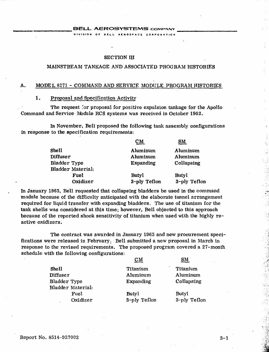
A. MODEL 8271 - COMMAND AND SERVICE MODULE PROGRAM HISTORIES
1. proposal and Specification Activity
The request for proposal for positive expulsion tankage for the Apollo Command and ServiceM:ldule RCS systems was received in October 1962.
In November, Bell proposed the following tank assembly configurations in response to the specification requirements:
CM SM
Shell Aluminum Aluminum Diffuser Aluminum Aluminum Bladder Type Expanding Collapsing Bladder Material:
Fuel Butyl Butyl Oxidizer 3-ply Teflon 3-ply Teflon
In January 1963, Bell requested that collapsing bladders be used in the command module because of the difficulty antiCipated with the elaborate tunnel arrangement required for liquid transfer with expanding bladders. The use of titanium for the tank shells was conSidered at this time; however, Bell objected to this approach because of the reported shock sensitivity of titanium when used with the highly reactive oxidizers.
The contract was awarded in January 1963 and new procurement speCifications were released in February ~ Bell submitted a new proposal in March in response to the revised reqUirements. The proposed program covered a 27-month schedule with the following configurations:
CM SM
Shell Titanium Titanium Diffuser Aluminum Aluminum Bladder Type Expanding Collapsing Bladder Material:
Fuel Butyl Butyl Oxidizer 3-ply Teflon 3-ply Teflon
Report No. 8514-927002 3-1
, ,j
- > ;.
•
__________ BELL AEROSYSTEMS COMPAI\IV _________ _
DIVISION OF DELI.. AEROSPACE CORPORATION
The proposal ·.vas reviewed and a coordination meeting 'was held to discuss schedule and technical problems. The schedule was reduced from 27 to 15 months and the development program was eliminated except for basic essential plexiglass tank testing. The go-ahead was given in March with efforts directed toward tailoring everything to achieve the shortened scheduk.
Early in April the decision was made to use Teflon bladders and stainless steel diffuser tubes in both the oxidizer and fuel tanks. The use of Teflon fuel bladders eliminated the need for parallel testing of the fuel and oxidizer tanks because of the difference in bladder configuration. By using the same design most testing could be accomplished on a worst case basis. The use of a stainless steel outlet was required for the brazed c011l1ection with the system plumbing.
In May, Bell submitted a proposal for the required 15-month program based on the follOWing tank assembly configurations:
Shell Diffuser Bladder Type Bladder Material
CM
Titanium Stainless Steel Collapsing 3-ply Teflon
Titanium Stainless Steel Collapsing 3-ply Teflon
This program excluded all development testing except for basic plexiglass tank testing and simulated bladder testing on material samples and "pipe" sections. The de~ign verification te.' ! t"ogram was to be initiated on a "high-risk" basis as soon as prototype hardware could bb jesigned and fabricated. The resulting program effort is shown in Fig1.l.'re III-1.
2. Design an~ Development
The design effort started with program go-ahead and changes were incorporated as they were made. All drawings were released by the end of May 1963. The service and command module tanks were designed to use interchangeable parts whenever practicable, and the required fabrication techniques were within the stateof-the-art. Vendor evaluation was in progress during the design effort to establish existing capabilities and inRure that the design was buildable.
Pressure vessel fabricators were evaluated to establish the existing capabilities for fabricating tank shells of aluminum, stainless steel, and titanium. Specifications (Book-form drawings) were prepared which contained all the detailed reqUirements for the titanium shells. These were the thinnest-walled pressure vessels known at that time and, as a result .• the requirements were extremely stringent to insure structural integrity. Trade-off studies were completed to establish acceptable limits based on industry capability and a reasonable advancement of the state-of-theart. As a result of these evaluations Airite was selected to fabricate the shells.
Report No. 8514-927002 3-2
f t I [
!
•
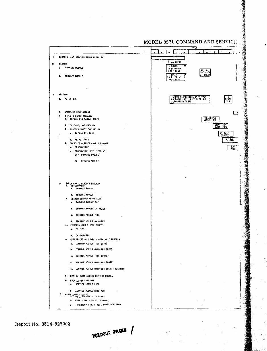
,ROPOSAl AND S'[CIrIUJlON ACtiVIT'
II DESltiH
I. COMMAND ..aDULt
•• SERVICE MO(lUl[
III TESlIfiCr
I. MATERIALS
t. D'NAMICS OnltOPf4£.NT
t. H't'!' BlADDER ,ROGNAM
,.
E.
1. 'LEXIGLA$S U,HK/BUDD(II
2. ORIGINAL Oyl PRD!iRAH
J, BLADDEH TWiST [VAlIIATiON
Ii. PLElIGlASS TANK
b. M£lIIL rINKS
•• DVERSt 2E BLADLER [uNF .GURU I 0"
•• DEV[LOPHtHT
b. tDNt"lOEIIC[ l[VE~ Tr,ST/Nti
(1) [tNtANtI MODULE
(2) SERVICE MODULE
I-PLY ~-MIL 8lIDDER PROGRAM I. O[y£lOPMENT
a. COftIANO MODULE
.. SERVICE MODULE
2. DESIGN VERIfiCATION TEST a. COftI:AND MODULE FUEL
•• tOfN.ND trJDUtE 0110 I IER
,. SERV I C£ foIODULr.' rUfL
•• SERVICE MaDill£: (J~ I Til lEA ,. COlfllltlD I/ODUlE' DEVr:LOI'r4rtH
a. at FU~t
•• CM OXIDlltR
•• QUILfFICJlTlOtl Li.vEL ~ OFF-LIMIT PROGRIIH
a. COMolIIJID MlDULF. rurl (On)
•• COfoMA,lD flOW' F. OIIOIUII (OVT)
,. SERVICE ~.oDUU: FUEL (QUAL)
•• SERVICt ";OvULE OXIfIIZER (QUilL)
.. S(IIVICE MODULF. DXIlIllER (C[nTlfICATIOIl)
s .. fleSllil1 susSTANTlON-COlfl/lI/D MODlllE
•• PRQPlllANT txPOSURF . .. SERVice H1DlllF. fliEl
.. SERVICE MODULF. OliOllER
PROprlLJINt STon4RE •• N204 STO AGr - to T/lttl"S .. fUEL IHMtf 1 501~O) STORIiGE
,. 11111111UM, IIil4 STRESS [Ofi!l{)510t; PROG,
Report No. 8514-927002
MODEL 8271 COMMAND AND SEBVICr:
, liD 'HUD
I" SHELL 1 I ~~,~'r~~H
l' " >HELL I I 50S DIHUSER )-PLY elAD
1 :'~M~At ,e'L7r;: I'~rr. ~~~;~IJANOJ SEPIAIT ION JUTS.
, illAIPl[ I SLOSH. OR' ,
r l [
•
, , I
!
I I.
,
..
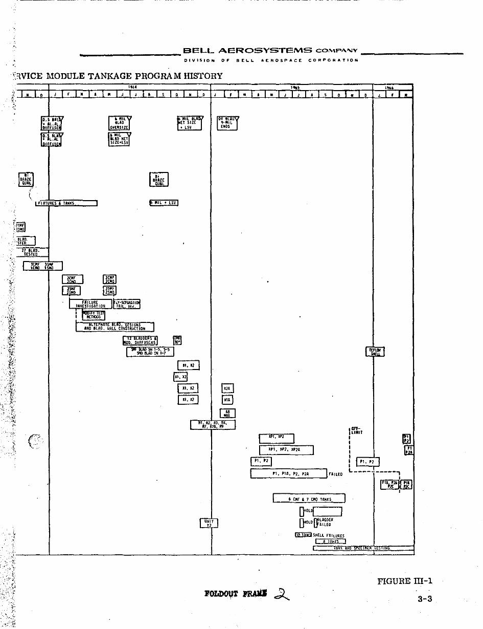
,," "H 'C n ------------- -- .. _---- . -_._-------
___________ BELL AEROSYSTEMS CO,"",P",,"V
DIVISION OF BELL A[.ROSPACE CORPORATION
'.
,\WICE MODULE TANKAGE PROGRAM HISTORY
l I" (0 ~'
'<
II EIIAl[ QUIL
~
J 1'1" 1'1- (,-,,1'1'10
• "ILJ IUD OV[IISllE
• JIlL :T ILID NET 51ZEtLSV
f~'UL 'L'j ET SIZE • LSV
. I fUTURES & liNtS e .UL' LSV'
.'
27 IUD. T£5T[C
I If:;; I rWiFl ~ . 1 f IIlURE I r~ ""-.·",,," ... "."',,01:1
INVESlIG!l.TlOH II FAI "iiiv:' I
112 BGWDERS 'I ~lO' !!9D. DIFFUS[RS. ~
( .. ,121
B B ~
1 RI~R2. ""oil" I "f, li7A, f!9
UliiT
"
... ,
lPl, IP2, IP2A
I ", " I IL ___ "_'_'_"_'_'_';..' _"_' __ -,1 fAILEO
I £> C"r , 7 00 T~N~S I 0""1 I £"\tOLD ff!LAQOr/{ U' lflolLED
....
L~I
Im;T : 1m ! jill I I"," 1 L ____ .L ____ ,
I ~ ~
•
,"', I A tAli(!; ,
I1«1Jl1( , ".ir, _____ L _____________________ L __________ ~h~Q ~trli=.~"'~EL~l~'~.~'l~"'~E~'~~~~~~===~ ':":
~ .. FIGURE ilI-l
3-3
__________ BELL Arc:ROSYSTEMS COMPANY _________ _
DIVISION OF DELL AER05PACE CORPORATION
All known Teflon bladder fabricators were surveyed for their ability to perform to the bladder fabrication requirements. As a result of these evaluations, Dilectrix Corporation was selected as the Teflon bladder vendor.
The selection of the vfmdor for the butyl bladder had not been completed at the time the decision was made to use Teflon instead of butyl for the fuel bladders. The state-of-the-art capability had been established and the most advanced fabricators were working with Bell during the material development program. These vendors also participated later in the program when butyl bladders were fabricated as part of an alternate bladder design effort.
Additional effort during this time included designs for an aluminum shell and titanium diffuser assemblies.
By July 1963 ,the design was considered 100% complete since all drawings had been released and the formal design review was completed. Minor changes had been made to the drawings during fabricatipn of the initial prototype hardware to ease manufacture. At this time,weight reduction became a major factor. Design changes were made to save weight at the sacrifice of interchangeability of CM and SM parts and extending fabrication times. These changes included reducing the wall thicknesses of the diffuser, retainer, and the SM flange. In addition, an evaluation was performed to check the feasibility of changing to an aluminum diffuser assembly. The change to aluminum bladder hardware was initiated and the design was completed in September. This design included the stainless-steel-to-aluminum bimetallic joint on the outlet port tubing to provide the stainless steel tube required for brazing to the system plumbing. Bi-braze Corporation was selected as the vendor and Bell personnel began working with them immediately to establish design parameters and fabrication techniques. Since this was a dissimilar metal union, compatibility tests were performed immediately and a qualification program was subsequently completed.
In Oct "ber 1963, vent lines were added to the design. The vent lines are external to the bladder and provide a passageway for gas to bleed from the blind end of the tank to the helium inlet port. The need for the vent lines as servicing aids was established during plexiglass testing when difficulty in venting the gas was encountered while draining the tank in the vertical flange-down position. At that time there was a requirement for repetitive expulsion cycling (50 cycles),one-third of which were in the vertical flange-down position. This 3-position requirement was for both the command and service module. For this reason,the vent lines were incorporated in both the CM and SM configurations.
In November, a new weight reduction program was initiated to substantially reduce the tank assembly weight. Excess material was removed from the shell boss and the aluminum diffuser hardware was incQrporated.
Report No. 8514-927002 3-4
f f _ f
L f -. t
, . i
t·
!
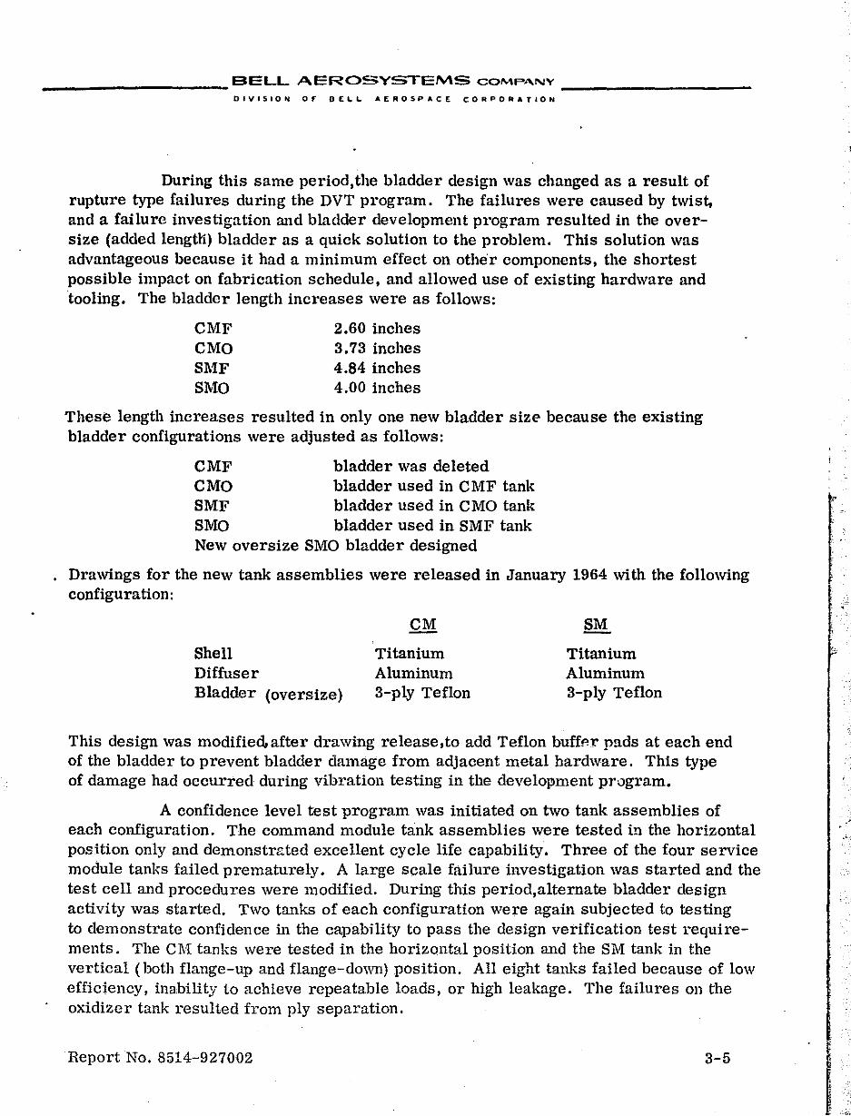
__________ BELL AEROSYSTEMS COMPA.NY __________ _
DIVISION OF DE",L AEROSPACE CORPORATIOH
During this same period,the bladder design was changed as a result of rupture type failures during the DVT program. The failures were caused by twist, and a failure investigation and bladder development program resulted in the oversize (added lengtli) bladder as a qUick solution to the problem. This solution was advantageous because it had a minimum effect on other components, the shortest possible impact on fabrication schedule, and allowed use of existing hardware and tooling. The bladder length increases were as follows:
CMF CMO SMF SMO
2.60 inches 3.73 inches 4.84 inches 4.00 inches
These length increases resulted in only one new bladder size because the existing bladder configurations were adjusted as follows:
CMF CMO SMF SMO
bladder was deleted bladder used in C MF tank bladder used in CMO tank bladder used in SMF tank
New oversize SMO bladder designed
Drawings for the new tank assemblies were released in January 1964 with the following configuration:
Shell Diffuser Bladder (oversize)
Titanium Aluminum 3-ply Teflon
Titanium Aluminum 3-ply Teflon
This design was modified"after drawing release,to add Teflon buffp-l' pads at each end of the bladder to prevent bladder damage from adjacent metal hardware. This type of damage had occurred during vibration testing in the development program.
A confidence level test program was initiated on two tank assemblies of each configuration. The command module tank assemblies were tested in the horizontal position only and demonstrated excellent cycle life capability. Three of the four service module tanks failed prematurely. A large scale failure investigation was started and the test cell and procedures were modified. During this period,alternate bladder design activity was started. Two tanks of each configuration were again subjected to testing to demonstrate confidence in the capability to pass the design verification test requirements. The C11[ tanks were tested in the horizontal position and the 8M tank in the vertical (both flange-up and flange-down) position. All eight tanks failed because of low efficiency, inability to achieve repeatable loads, or high leakage. The failures on the oxidizer tank resulted from ply separation.
Report No. 8514-927002 3-5
•
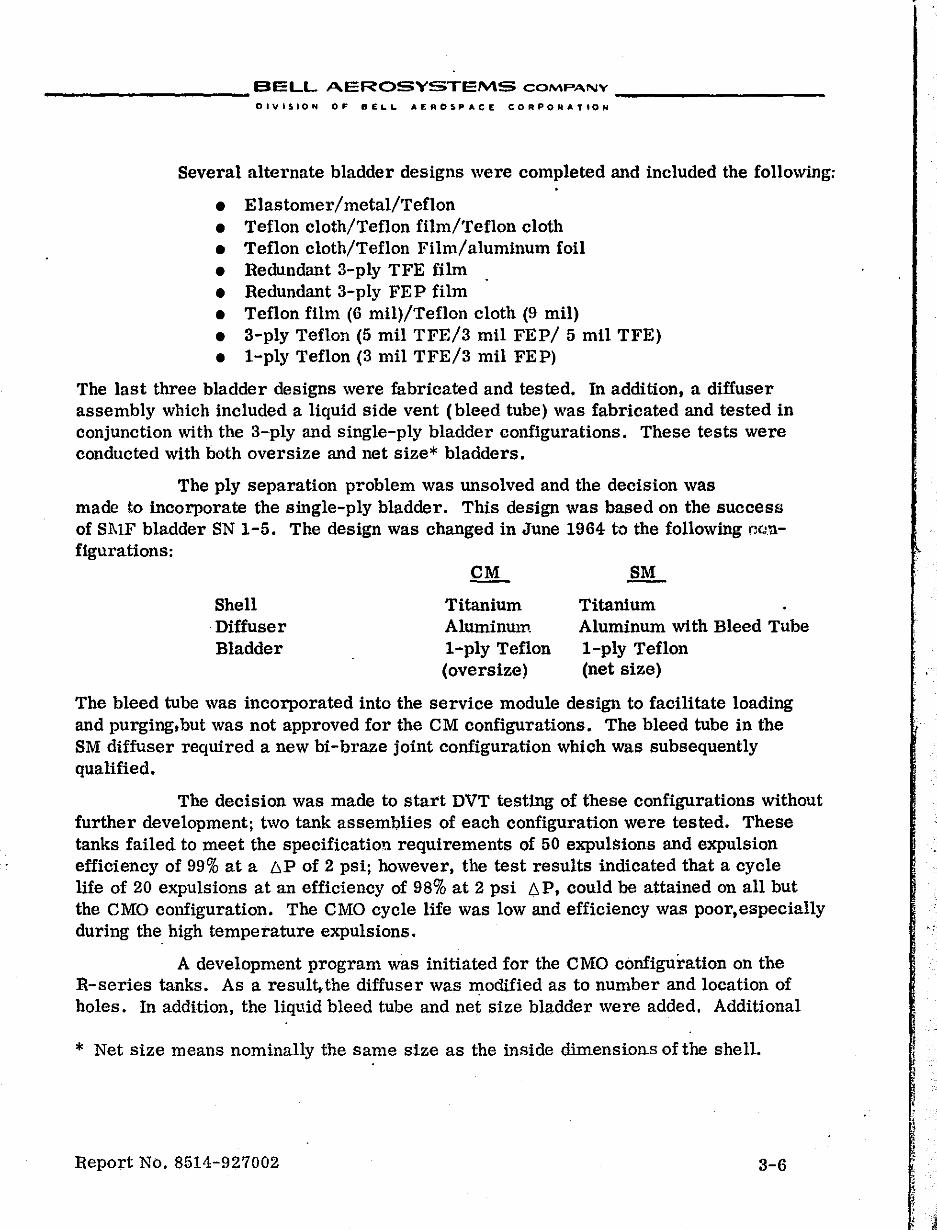
__________ BELL AEROSYSTEMS COMPANY _________ _
DIVISION OF BELL AEROSPACE CORPORATION
Several alternate bladder designs were completed and included the following:
• Elastomer/metal/Teflon • Teflon cloth/Teflon film/Teflon cloth • Teflon cloth/Teflon Film/aluminum foil • Redundant 3-ply TFE film . • Redundant 3-ply FEP film • Teflon film (6 mill/Teflon cloth (9 mil) • 3-ply Teflon (5 mil TFE/3 mil FEP/ 5 mil TFE) • 1-ply Teflon (3 mil TFE/3 mil FEP)
The last three bladder designs were fabricated and tested. In addition, a diffuser assembly which included a liquid Side vent (bleed tube) was fabricated and tested in conjunction with the 3-ply and Single-ply bladder configurations. These tests were conducted with both oversize and net size* bladders.
The ply separation problem was unsolved and the deciSion was made to incorporate the single-ply bladder. This design was based on the success of Sl\lF bladder SN 1-5. The design was changed in June 1964 to the following configurations:
Shell Diffuser Bladder
QL Titanium AluminulI1. 1-ply Teflon (oversize)
SM
Titanium Aluminum with Bleed Tube 1-ply Teflon (net size)
The bleed tube was incorporated into the service module design to facilitate loading and purging, but was not approved for the CM configurations. The bleed tube in the SM diffuser required a new bi-braze joint configuration which was subsequently qualified.
The decision was made to start DVT testing of these configurations without further development; two tank assemblies of each configuration were tested. These tanks failed to meet the specification requirements of 50 expulsions and expulsion efficiency of 99% at a 6P of 2 psi; however, the test results indicated that a cycle life of 20 expUlsions at an efficiency of 98% at 2 psi 6P, could be attained on all but the CMO configuration. The CMO cycle life was low and efficiency was poor, especially during the high temperature expulsions.
A development program was initiated for the CMO configuration on the R-series tanks. As a result,the diffuser was modified as to number and location of holes. In addition, the liquid bleed tube and net size bladder were added. Additional
* Net size means nominally the same size as the inside dimensions of the shell.
Report No. 8514-927002 3-6
j
•
.,
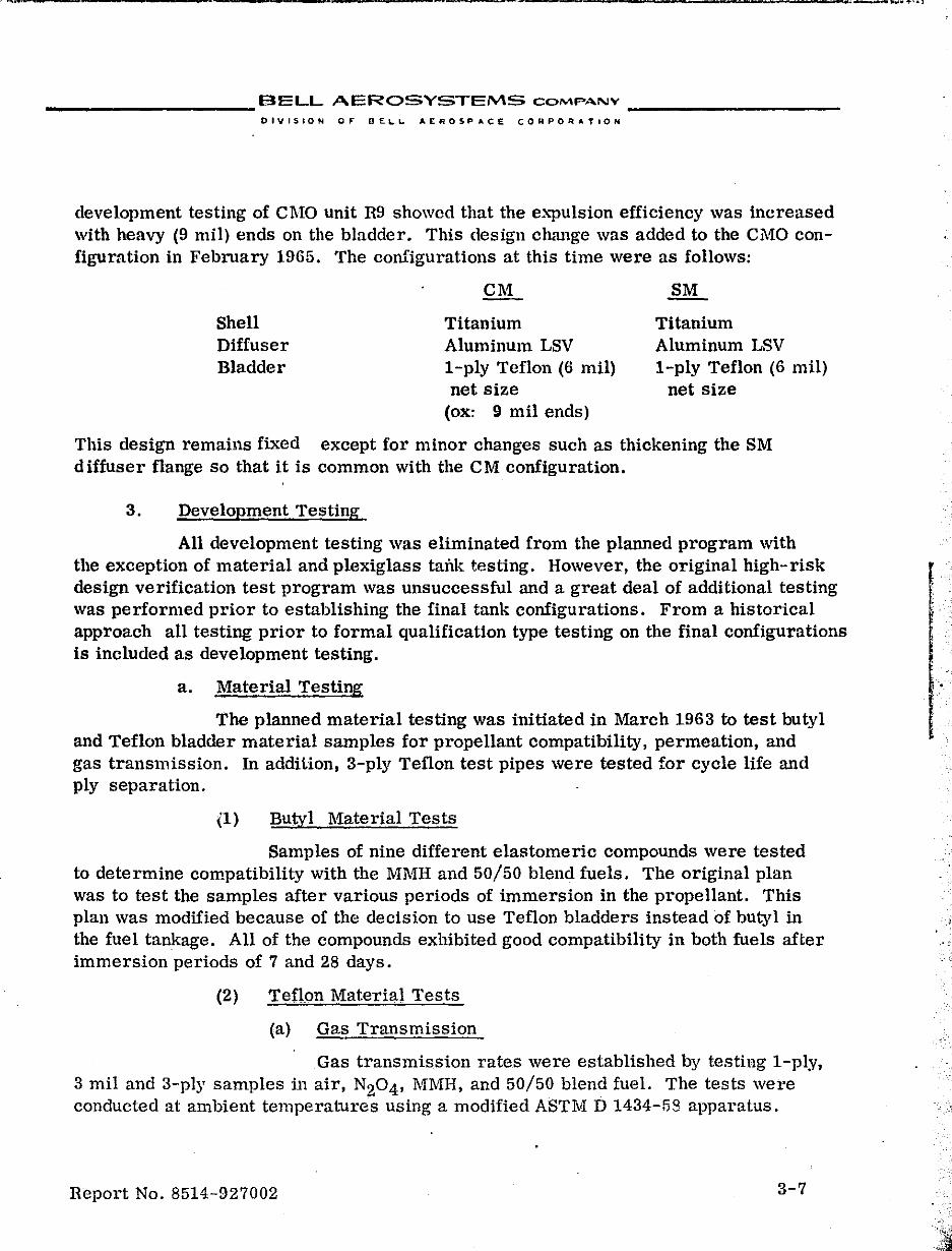
" • 'W '-.. ·_ ..... "f-'.l
__________ BELL AEROSYSTEMS COMPANY _________ _
DIVISION OF BEL.l.. AEROSPACE COHPORATION
development testing of CMO unit R9 showed that the e""pulsion efficiency was increased with heavy (9 mil) ends on the bladder. This design change was added to the Ci\1:0 configuration in February 1965. The configurations at this time were as follows:
Shell Diffuser Bladder
CM
Titanium Aluminum LSV I-ply Teflon (6 mil) net size
(ox: 9 mil ends)
Titanium Aluminum LSV 1-ply Teflon (6 mil)
net size
This design remains fixed except for minor changes such as thickening the SM diffuser flange so that it is common with the CM configuration.
3. Development Testing
All development testing was eliminated from the planned program with the exception of material and plexiglass tank testing. However, the original high-risk design verification test program was unsuccessful and a great deal of additional testing was performed prior to establishing the final tank configurations. From a historical approach all testing prior to formal qualification type testing on the final configurations is included as development testing.
a. Material Testing
The planned material testing was initiated in March 1963 to test butyl and Teflon bladder material samples for propellant compatibility, permeation, and gas transmission. In addition. 3-ply Teflon test pipes were tested for cycle life and ply separation.
(1) Butyl Material Tests
Samples of nine different elastomeric compounds were tested to determine compatibility with the MMH and 50/50 blend fuels. The original plan was to test the samples after various periods of immersion in the propellant. This plan was modified because of the decision to use Teflon bladders instead of butyl in the fuel tankage. All of the compounds exhibited good compatibility in both fuels after immersion periods of 7 and 28 days.
(2) Teflon Material Tests
(a) Gas Transmission
Gas transmission rates were established by testing I-ply. 3 mil and 3-ply samples in air, N204, MMH, and 50/50 blend fuel. The tests were conducted at ambient temperatures using a modified ASTM D 1434-53 apparatus.
Report No. 8514-927002 3-7
·-'rrj -~~
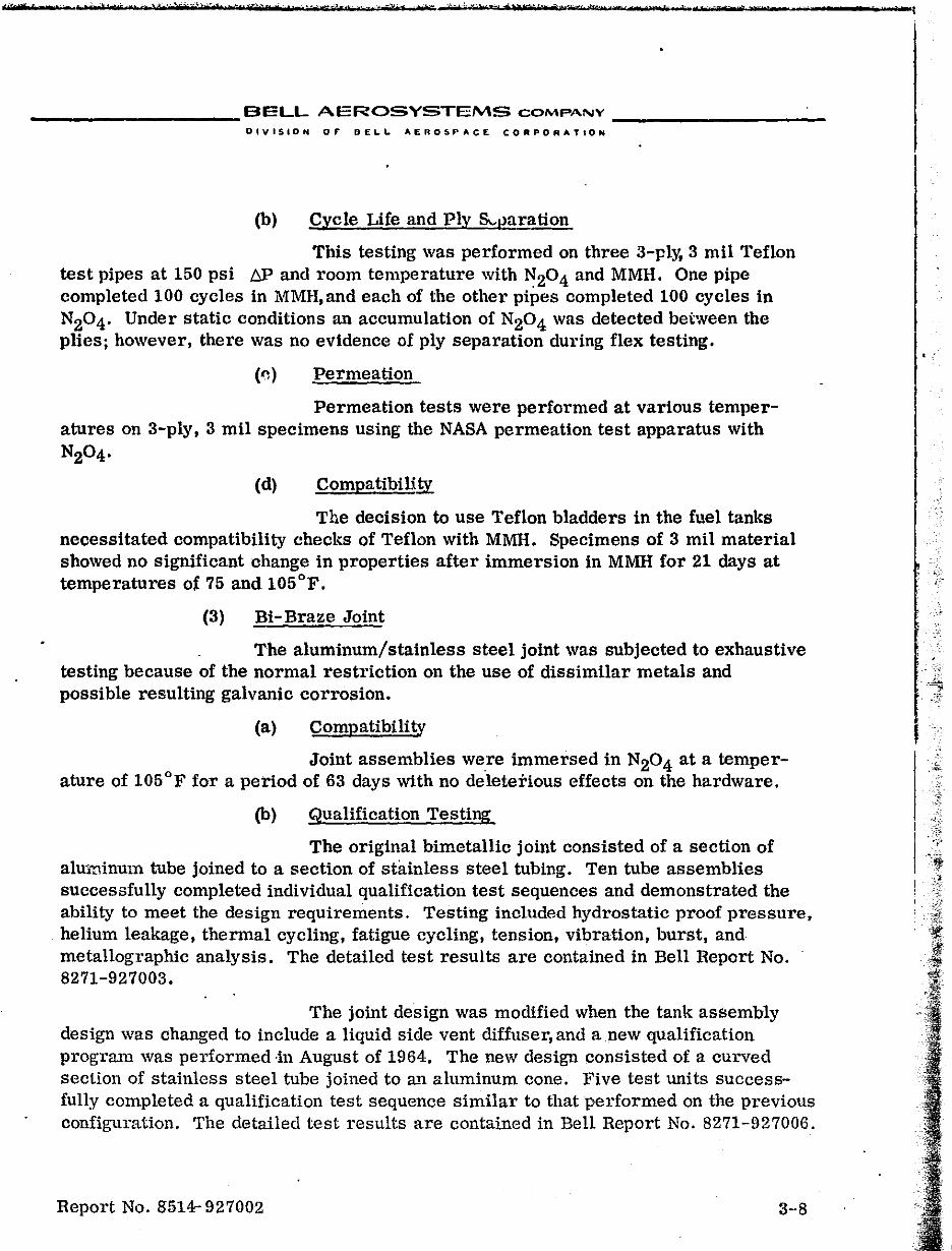
.-trW· tt t 1
__________ BELL AEROSYSTEMS COMPANY __________ _
OlVISION or DE!..&" AERO!tPACE CORPORATION
(b) Cycle Life and Ply S"I)aration
This testing was performed on three 3-ply, 3 mil Teflon test pipes at 150 psi !:::P and room temperature with N20 4 and MMH. One pipe completed 100 cycles in MMH, and each of the other pipes completed 100 cycles in N204' Under static conditions an accumulation of N20 4 was detected between the plies; however, there was no evidence of ply separation during flex testing.
('l) Permeation
Permeation tests were performed at various temperatures on 3-ply, 3 mil specimens using the NASA permeation test apparatus with N204·
(d) CompatibiH!y
The deciSion to use Teflon bladders in the fuel tanks necessitated compatibility checks of Teflon with MMH. Specimens of 3 mil material showed no Significant change in properties after immersion in MMH for 21 days at temperatures of 75 and 105°F.
(3) Bi-Braze Joint
The aluminum/stainless steel joint was subjected to exhaustive testing because of the normal restriction on the use of dissimilar metals and possible resulting galvanic corrosion.
(a) Compatibility
Joint assemblies were immersed in N20 4 at a temperature of 105°F for a period of 63 days with no deleterious effects on the hardware.
(b) Qualification Testing
The original bimetallic joint consisted of a section of aluminum tube joined to a section of stainless steel tubing. Ten tube assemblies successfully completed individual qualification test sequences and demonstrated the ability to meet the design requirements. Testing included hydrostatic proof pressure, helium leakage, thermal cycling, fatigue cycling, tension, vibration, burst, and metallographic analysis. The detailed test results are contained in Bell Report No. 8271-927003.
The joint design was modified when the tank assembly design was changed to include a liquid side vent diffuser, and anew qualification program was performed ·in August of 1964. The new design consisted of a curved section of stainless steel tube joined to a.11 aluminum cone. Five test units successfully completed a qualification test sequence similar to that performed on the previous configuration. The detailed test results are contained in Bell Report No. 8271-927006.
Report No. 8514- 927002 3-·8
n (
. .
· _~._._ .. _' ...... '_'_~r ............. ; ______ . It. IStCfI-tS ".J
__________ BELL AI:::ROSYSTEMS COMP.'NY _________ _
DIVISIO-, OF DELI.. AEROo:.,PACE CORPORATION
h. Plexiglass Tank Test Program
PJexiglass test tanks were designed and fabricated for the command and service modules with extra center sections so they could be used for either the fuel or oxidizer configurations. These tanks permittE'd visual observation of the action of the 3-ply bladder; however, testing was limited to simulated propellants at a maximum pressure of 40 psig. The test series for each configuration conSisted of slosh, loading and expellitlg, and drying evaluations.
(1) Load and Expulsion
This testing was performed on each configuration to refine the procedures and demonstrate the capability of being loaded and expelled in all three attitudes - horizontal, vertical flange-down, and vertical flange-up. The vacuum loading technique was used on all configurations. A problem arose in servicing in the vertical flange-down pos~tion because of the inability to vent the gas trapped between the bladder and shell. The problem had been antiCipated because of experience from previous programs. The addition of vent lines alleviated the problem.
The eMF configuration was subjected to life cycle testing to demonstrate the 50-cycle capability with all tests performed at a maximum temperature of 40°F. Thirty-six expUlsions (16 horizontal, 17 vertical flange-up, 3 vertical flange-down) were completed prior to bladder failure. The failure was caused by the low tempcrature effects coupled with the twisting action noted during the horizontal cycles.
as follows: A new bladder was installed and 50 cycles were' completed
8 expulsions at 40°F horizontal 8 expulsions at 70°F horizontal
17 expulsions at 70°F vertical, flange-up 17 expulsions at 70°F vertical, flange-down
(2) Slosh
All four configurations were subjected to low frequency vibration scans to establish the major liqUid natural frequencies. The tests were completed without incident.
(3) Drying Evaluation
Vacuum drying techniques for use during production acceptance test were evaluated using methyl,,:ne chloride and methyl alcohot at ambient and low temperatures.
Report No. 8514-927002 3-51
-.~'.-.~,",'~''---~~''-------.------~-----.-------------~~ ..... _---
__________ SELL AEROSYSTEMS COMPANY ___ ....,. _____ _
"1\'11510", OF DELL AeROSPACE CORPORATION
c. Initial Prototype (DVT) Test Program
This program, started in September 1963 before completion of the plexiglass tank testing, was the initial testing on the prototype metal tank assemblies. The testing was performed in accordance with the then current specification sequence and requireme!l~.s. The expulsion cycle demonstration required 50 propellant expulsions, each of which was conducted with a differential pressure of full tank assembly operating pressure across the bladder at the end of the expulsion. In addition, each configuration W:1S tested in all three attitudes and at high, ambient, and low temperatures. Eight tank assemblies, two of each configuration, were to be subjected to the DVT sequence and, in addition, one CMF and one SMO tank shell were to be pressure cycled and burst. The test results of each configuration were as follows:
CMO Unit Xl completed 16 propellant expulsion cycles ~ cluding 8 at 40°F in the horizontal pOSition and 8 at 70°F in the vertical flange-up position. During fill for the 17th expulSion, after changing to the flange-down position, a failure was evident. The pladder was torn through all three plies and had the appearance of being burst. The tank assembly was refurbished with a new bladder and held for future testing.
, C:MO Unit X2. completed acceleration and started vibration testing when the bladder failed. The tank assembly had been fully loaded in accordance with the requirements and the internal pressure buildup during vibration forced the bladder against the edges of the holes in the "showerhead" ring causing the failure. The procedures were changed to allow proper ullage capacity during testing and. as a result of this failure, Teflon buffer pads were added to eacl. end of the bladder to protect it from damage by the bladder hardware. These pads were tested during vibration development and were incorporated into the design in December 1964.
CMlr Unit Xl was held pending solutions to the other tank failures and was later used in the bladder devel0tlment program.
CMF Unit X2 completed acceleration testing prior to the start of the vibration testing. During the random vibration run the helium port fitting fractured because of improper fixturing. The fixtures were modified and the tank assembly was refurbished for future testing.
Report No. 8514-927002 3-10
,-.
, .~
......... h~, _' ... # ....... '$ .... ·· .... ' .... '1 ":"''''''1'*"",' _ .... " ............ ·X ... ·.,.·, .... ' ... ' ... t ',.." _' ... ·' ... tt"'e ..... • ... ' r_M""'< • ... k""·s' ... "_. ' __ '_" .... b1 ... ''''"'·, •• _,''-· .... ' .";,,,,-,,,,,*,,,, _.·_U·_ ....... t'""'.'-"" ... · t....;.., ..... ~,_,_, ... __ ¢'~' ''' ....... ~._, ........... ~ .. ~~
_.~ _________ BELL ,~EROSYSTEMS COMPANY ________ , __
OIVISION 0,. e£Lt.. AE"OS~.CE CO,.rORATIOH
eMF Unit X3 completed the specified 3000 press'lre cycll3s prior to being burst. The resulting burst pressure was 1049 psig. * SMF Units Xl and X2 were not tested. The units were held for future testing.
SMO Units Xl and X2 were not tested because of the bladder failures encountered wHh the command module configurations.
SMO Unit X3 completed the required 3000 pres 'lure cycles and was burst at a pressure of 567 psig. *
d. Development Test
Although the original development program had been deleted, it became necessary to reinstate a development effort because of the twisting type bladder failures and vibration fixturing problems. All de:sign verific!ttion testing was stopped and development programs were established in each of these areas:
(1) Dynamics Development
This program was initiated in November 1963 to solve the tank assembly and fixture problems encountered during DV-:r where bladder failures had occurred m',ring vibration vvith the box type fixtures. The original plan was to test the tank assemblies concurrent with the evaluation of redesigned fixtures and optimized equdization techniques. The scope of the program was expanded tc, include evaluation of tank assemblies with aluminum diffusers and oversize bladders.
(a) Fixture Redesign
Each tank assembly was to be vibrated in three axes -one 10ngH:udinal and two lateral. During the original DVT testing, problems arose on trying to equalize b(~cause of the fixturing. Several companies and laboratories were consulted regardini; fixture design and random vibration equalization techniqueB. As a result, new fixtures were designed - circular plate for the command module, and t'.lbular type for the service module.
(b) Tank Assembly/Fixture Testing
The command module units tested with the box type fixture during DVT- ):esulted in bladder failures during the random equalization runs. Three additional wits, one fuel and two oxidizel', were tested with the circular plate
* (Additional burst test data were obtained in November 1963 by burst testing of one CMO and one CMF shell Which had been rejected because of excessive porosity and mismatch. The resulting burst pressures, after completion of pressure cycling, were 920 and 1020 psig, respectively.)
Report No. 8514"')27002 3-11
i
f .'\ I
.. I I
-----------~,~"-------------------~--~--~--------~--------*'~' ~----------~--,----~~----~
__________ BELL AEROSVsTEMS COMPANY __________ _
OIVISIOH 0,. .£ ..... AE"OG~ACE cO""OIll:ATION
fixture. The fuel unit was tested successfully; howeve,r, the first oxidizer unit test resulted in a b~adder failure during endurance testing. A second oxidiz~r test with an oversize bladdel' was successful except for mounting bolt problems.
All service module testing was performed using the tubular fixtures. Six test units, three fuel and three oxidizer, were tested. One fuel and one oxidizer without bladders were used for lateral axis fixture checkout. Mounting bolt problems were encountered and the necessary modifications were
, malle. Some mounting bolt problems were evident during testing of the remaining fOUl units; hnwever,the tank assemblies successfully withstood the required vibration Input~ New high,·strer.gth bolts were used for subsequent testing;
,2) Bladder Development
This program was undertaken to solve the twisting problem as quickly as possIble with minimum effect on the hardware configuration. The effort was directed toward p ... ocedural changes which would negate the effects of twisting and minor h!'~dware modifications which ,would prevent twist or failures due to twist. PotentIal hardware changes included the following:
• Controlled-fold devices • Finned diffuser • Multiple vent lines • Undersized bladder • Oversize (length) bladders • Liquid side vent (bleed tube) diffuser
In addition, the bladder fabrication process was monitored find evaluated to determine if the twist was inherent because of the technique of spraying a rotating mandrel. This theory was not slt;,stantiated by the investigation. Approximately 50 bladder tests were performed in both plexiglass and metal tanks during this development program. The hardware and procedural modifications were first tested in plexiglass tanks with simulated propellant and then, if a concept showed potential, it was tested in the metal tanks with propellant.
(a) Procedural Changes
Atter 'pts were made to prevent rupture type failures resulting from twisting by controlling load pressures and flow rates. In addition, repOSitioning by cycling the b13dder with gas prior to each load was attempted. Several variations and combinations of gas cycling, pressure, and E"racuation techniques were attempted with the tank assembly in each of the three required orientations. A ~atisfactory procedure was established for the command module tanks and the 50-cycle requirement was demonstrated on four tanks of each configuration, using water as the test liquid. These procedures did not alleviate the twist problem in the longer service modul,. tank assemblies.
Report No. 8514-927002 3-12
•
•
.,
"-2+"."10'''' tv 'j'."";"';;' '.<$"-"" -"'M"ts'a-ta'tr N' MI!! Pt"N/'t ("'''',,''6 "'i'*,,, II ,,1"o"H $,5_ '"'_'). f .t" •• fl" ~'tb'M~'*'r'd,
___________ BELL AEROSYSTEMS COMPANY _' _________ _
DIVISION OF" DEL.L AI.AOSPACE CORPORATION
(b) Controlled- Fold Devices
Activity on these deVices was limited to a design effort. No workable design was established because of the tank assembly configuration and the susceptability of the bladder material to damage from mecha.i'lical restraining devices.
(c) Finned Diffuser Tube
A diffuser assembly with anti-twist fins attached longitudinally to the diffuser tube was fabricated and tested in plexiglass and metal tank assemblies. This concept showed some potential but no further testing was performed. because of the success of the oversized bladder described below.
(d) MultipleVent Lines
A bladder assembly was built up with eight (instead of the standard two) vent lines to prevent localized gas pockets and permit more uniform gas flow between the bladder and shell. Testing in the plexiglass tank indicated that there was no improvement in the twist problem with this configuration.
(e) Undersize Bladder
A CMF bladder was shrunk so that it was approximately liS-inch undersize. This unit was tested in the plexiglass tank at very low pressure and successfully completed 50 cycles with little twist; however, the concept was abandoned because it was felt that the undersize characteristics would be lost because of stretching.
(f) Liquid Side vent Diffuser
A diffuser was modified to include a liquid side vent (bleed) tube to permit liqUid loading with the bladder expanded. This concept eliminates the Vilcuum loading technique for the vertical position and facilitates servicing. One test of 33 cycles was perlvrmed in the plexiglass tank with minimal twist. No additional testing was performed at this time because this concept was not applicable to the horizontal loading requirements of the command module configuration.
(g) Oversi.ze Bladder
The oversize bladder concept was based on the idea that the additional length would permit twisting without the burst-type failures. A test summary is presented in Figure 1II-2. 'l'hefil'st trial was testing of a SMO bladder in the SMF plexiglass tank. Fifty cycles were completed without failure. A new SMO bladder was installed in.a metal tank and 126 water expUlsions were completed at standard pressures and flow rates before bladder failure. The next test was a CMO bladder in a CMF metal tank which completed 61 water expulSions prior to failure. Testing of these units was performed in all three attitudes.
Report No. S514-!'J27002 3-13
! I t
~ '0 o :+ ~ . cc. en t-' H>I ~ Nl ~ o o Nl
~ I
t-' H>-
Y.'
.,.y •• CcmnanlJ Module Fuel 2.60 In. OVlu'ai:&e
CCWRIlnd Module OJ:ldlzer 3.73 In. Overalze
3e:rvlce Module FUel 1.j.84 in. Oversize
Service HlXIule ,Qxldber ~.OO In. overel%e
Bl:=~er I ~; 24-3 66 11-3 73 31-3 74 27-3 77 18-3 87 29-3 93 32-3 l:21
36-3 121-
23-5 74 34-5 63 29-5 66 38-5 87 35-5 9. 27-5 122 30-5 122
16-7 48 20-1 56 23-7 74 33-7 91 40-7 90 36-7 96 13-7 97 42-7 9B 47-7 10< 49-7 '''' 4<>-7A
58-7 11
59-7 u 1~29 74 1-33 79 2-33 sa 5-33 -6-33 120
20-33 120
FIGURE ill-2 MODEL 82713-PLY OVERSIZE BLADDER TEST SUMMARY
lqbl 1q
." 2 1 , • 1 1 mj(15 In 17- " 51 .. , e •• 1 .11 - ~ - Water Tcatlns
!lll . ) 24 .. EZI .. Propellant TeatlnK 16- , 0 alua .an r • ••• tln .. . ,. •• 'or to 11 P l!Z (1 -17 17 16- ITt n 6- I ) 19_ • P 0,0( .. vol tl. - ! ,." .. Cycles
I:i:I' (16 -17 In 3-) 53 • .L. S P .. '-tIed
~ 13 -., C.L· - S S .. SatIBfactory
!' h •• • or - ~ r.' • Bl "". 56- •. -• C.L.- Conridence Level Teat
. ~ o b dde 0.." rat • I .r -1l'I'I I:;'~ i" -21 -. r eloJ: ont ., od .'''' I Pr -Wl - 33_ S
C!1: Sl ( ~-4 ') ON r. .b. It, • ,.~6 3' 19 .. . .L. P
v. "'. "lb Mltl " d.
010 !!lent r'. 3B .. . L. P
1 11 -.. .L • S . 10 -"I C.L -
Pr -.,.., 11 ~- , p,., -Wl iW-il!I f-13 .- .
m; 6' 7' -) 5010 , P ••• ank to. 'b' It, S I B(1 • 1 , 1 .,6 171 17- IG' O. 126 rv, lillie btl , -.
Iii (I. 10 3- 29 ~. P. lur.on - S ~ 7. • .L ... P .
~ I '''' ,C'iL' - • ::;E: (16 161 18- 6. 66 ~ .. +50· , - S
16! 7' 7-1 ~.) 66" .t 50- , .1 ... rt - S .
~ 12.· rw· +5< •• ..t ent -
~~5 ~, .. • .t .nt • N ." ~ .. . - P ., •• t - (16 17 17· 3.) 3N
Or -Wl m;:; pu rv' Or -Wl EZ.l 5'" I-P
0·5 neh .... 1 •• bl •• .r - len ~ (16 151 I 3 N • •• (1 , 1 H7 .16 17t 17- 6, it ~) '"'' •• S
e 6' .... ~.L. - P ~. (16' 17. 7- 6. ) 06 ow ent a
,i ·fN . ~. (Ill " 13 I ::: p, _mI (1" I, ".
~, t. ',"'1.-+ ,::::_p ll; ,. j ,i P'PI,L-"
'",. '" -~
!
~ OJ ~ m :: r ~ r o ) ~ m : iJ ~ 0 • Ul .. -(
~ Ul M -I : m ~ ~
Ul n o
• n ~ 0 ~ ~ • :0 .. » ;; z z 0(
I
l
-~ . ''''it -eN" - l ~ .. -. $&" 'f ''/' -eel he '''~-'',wi:.If "Uti" '. tr'ad tt·, IT 77 It _!, .... -1 .. ., -N ._It ',.6""5'-'" t f 'VA'H. ,.' bed t)'if' r "e.,'
__________ BELL AEROSYSTEMS COMPANY __ ~ ________ _
O'VISION OF BELL AEROSPACE CO"PORATION
Based on the success of these tests, emphasis was placed on the oversize bladder as a solution to the twist failures. The oversize configuration resulted ill a minimum effect 011 other components and had minimum effect on the schedule because existing hardware and tooling could be used. The additional bladder lengths w!'re attained by using the CMO bladder in the CMF tank, the SMF bladder in the CMO tank, the SMO bladder in the SMF tank, and a new oversize bladder in the SMO tank. The other concepts were abandoned so that hardware and effort could be concentrated on meeting the program schedule with the oversize design. During December 1963,additional oversize bladders were tested with water to refine loading and servicing procedures and acquire cycle life data. This testing demonstrated that the 50 expulSion cycle life was attainable. Testing in January 1964 was"delayed until additional bladders of the required configurations could be fabricated for use in confidence level testing.
e. Confidence Level Testing-Oversize Bladders
This test program was started in January 1964 with suncessful completion of 53 cycles in all three attitudes at 50°F on a CMF tank (Bladder SN 27-3). The aluminum diffuser and oversize bladder were incorporated into the design based on this test coupled with the results of the development program. The intent of this program was to establish a level of confidence in the ability to . pass the DVT 50-cycle requirement by testing two units of each configuration to the speCification expulsion requirements, except all testing was performed at 50°F.
(1) Command Module
The first CMO unit (Bladder SN 34-5) failed aft~r 19 cycles, of which the last three werl;! vertical. The previous expulsion test with water (Bladde-r SN 23-5) had resl.I.lte'i !1} failure after 20 cycles with the last four vertical. Based on the results of tb~"f;; t~·.;·i"S it was decided to test four additional command module tanks to failure with t~H' tests performed at 50°F in the horizontal pOSition only. The results were as follows:
CMF (Bladder SN 18-3) completed 132 MMH expulSions in the horizontal position without failure ..
CMF (Bladder SN 29-3) completed 50 MMH expulSions in the horizontal position prior to failure.
c1\10 (Bladder SN 29-5) had previously completed the DVT vibration test during vibration development. Since the unit was available, expulsion testing was performed prior to disassemLly and -refurbishment. The unit completed 38 N20 4 eX'Pulsi<:ms in the horizontal position prior to failure.
Report No. 8514 927002 3-15
, f ., 1 . T C t ,t'$'_'. ""';-'1,,,1 Il e" ) ......
BELL AEROSYSTEMS COMPANY _________ _
'SION 0, BEl.l. AE"OSPACE CORPO~ATION
CMO (Bladder SN 38-5) completed 116 horizontal expulsions with N204 without failure.
CMO (Bladder SN 35-5) completed 108 horizontal expulsions with N204 without fail\lre.
The resu.1ts of these tests indicated that the 50-cycle life requirement was easily attainable if the testing was performed in the horizontal attitude.
(2) Service Module
Previous expulsion testing with water had indicated good cycle life. The propellant testing in all three attitudes was started on the oxidizer tanks and the first test was very successful. The results of the four confidence level tests were as follows:
SMO (Bladder SN 1-33) completed 140 N204 expulsions wiL'lout failure.
SMO (Bladder SN 2-33) failed after completion of six vertical expulsions.
SMF (Bladder SN 33-7) failed after seven vertical expulsions.
SMF (Bladder SN 40-7) failed after three vertical expulsions.
The confidence level testing of the service module configurations was stopped and a thorough investigation of the three premature failures was started. -
f. Confidence Level Test Failure Investigations
The investigation of the Service Module bladder failures was initiated immediately. A very extensive compilation of variables which could occur in fabrication, assembly, and test was assembled in matrix form for bladders that were tested without failing versus bladders which failed prematurely. This matrix of variables failed to determine conclusively the cause of failure; however, many possibilities such as raw materia.l problems, bladder fabrication, faulty hardware, and assembly methods were eliminated. The variables which remained as possible causes of failure were the effects of 50/50 fuel blend on the bladder material and the low temperature and high humidity encountered during assembly, shipping, and storage. The 50/50 fuel blend was investigated because with one exception all premature failures occurred during tests with this propellant. The one exception was the failure of a service module oxidizer bladel.er that appeared to have been damaged during assembly. The material, heat transfer effects, test procedures,
Report No. 8514-927002 3--16
%t
. -~' j~~ ~-,:'i,
-,-.
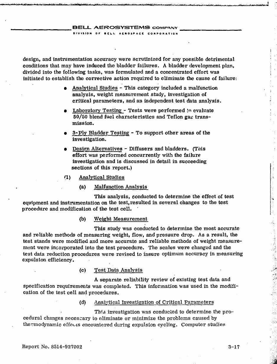
__________ BELL AEROSYSTEMS COMPA.NY ___________ _
DIVISION or IIELL. AEROSPACE CORPORATION
design, and instrumentation accuracy were scrutinized for any possible detrimental conditions that may have induced the bladder failures. A bladder development plan, divided into the following tasks, was formulated and a concentrated effort was initiated to establish the corrective action required to eliminate the cause of failure:
• Analytical Studies - This category included a malfunction analysis, weight measurement study, investigation of critical parameters, and an independent test data analysis.
• Laboratory Testing - Tests were performed tn evaluate 50/50 blend fuel characteristics and Teflon gat: transmission.
• 3-Ply Bladder Testing - To support other areas of the investigation.
• DesiP.;l1 Alternatives - Diffusers and bladders. (This effort was performed concurrently with the failure· investigation and is discussed in detail in succeeding sections of this report.)
(1) Analytical Studies
(a) Malfunction Analysis
This analysis, conducted to determine the effect of test equipment and instrumentation on the test, resulted in several changes to the test procedure and modification of the test cell.
(b) Weight Measurement
This study was conducted to determine the most accurate and reliable methods of measuring weight, flow, and pressure drop. As a result, the test stands were modified and more accurate and reliable methods of weight measurem~mt were inc.orporated into the test procedure. The scales were changed and the test data reduction procedures were revised to insure optimum accuracy in measuring expulSion efficiency.
(c) Test Data Analysis
A separate reliability review of existing test data and specification reqUirements was completed. This information was used in the modification of the test cell and procedures.
(d) Analytical Investigation of Critical Parameters
Thi .., investigation was conducted to determine the pro-· cedural changes neces.c.ary to eliminate or minimize the problems caused by thecmodynamic effeL~s encountered during expulsion cycling. Computer studies
Report No. 8514-927002 3-17
. ,
-.
.' -',
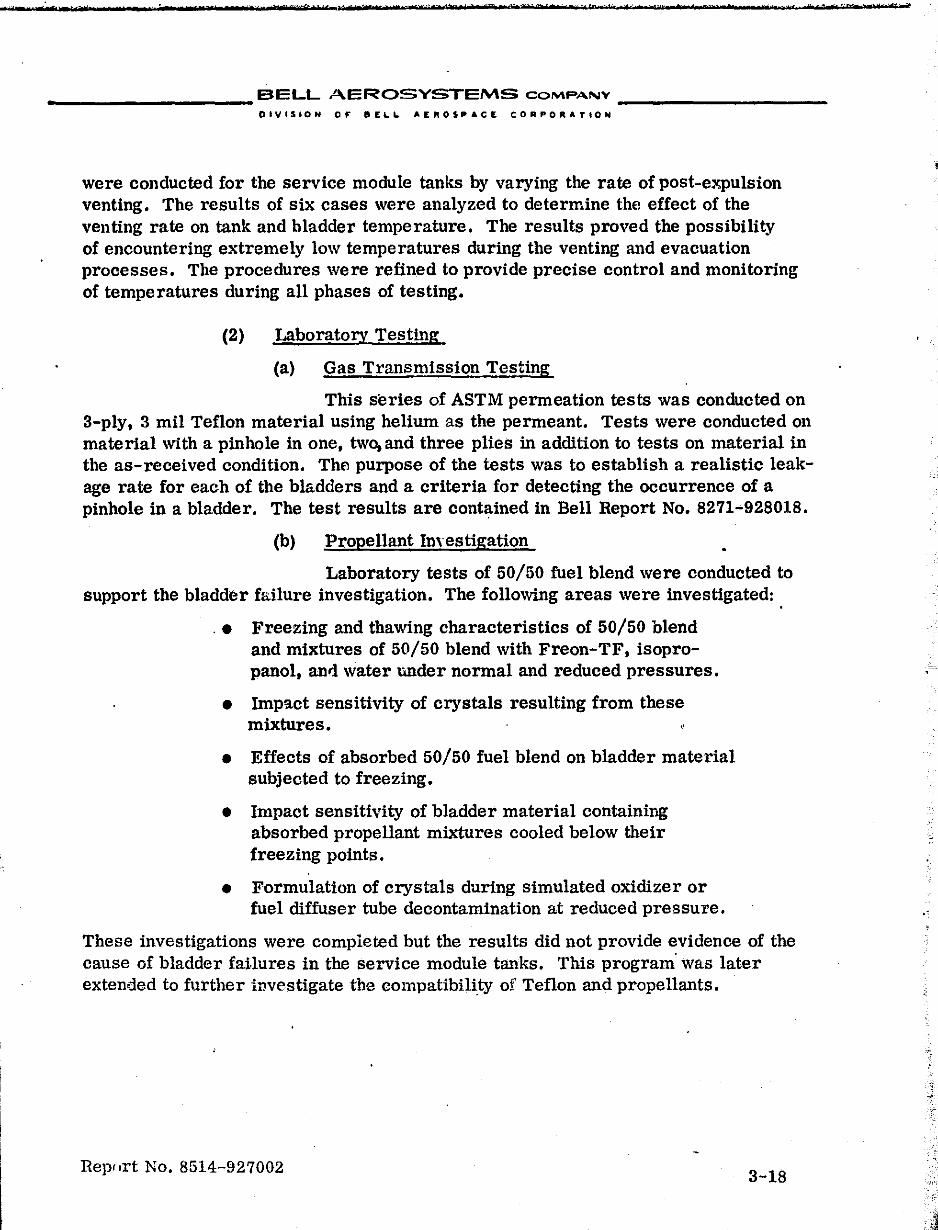
d±lltn «&tntpe! Met ":1:1'" . 1" b .. VY ... • 1t·$" - m 'n-'." Ie 1 ••• 11ft tor :, t file e ' r ,1m MS-,;*, rd
__________ BELL AEROSYSTEMS COMPANY __________ _
DIVISION 0,. 8E~~ AE"OS~ACIE CORPORATION
were conducted for the service module tanks by varying the rate of post-expulsion venting. The results of six cases were analyzed to determine th{l effect of the venting rate on tank and bladder temperature. The results proved the possibility of encountering extremely low temperatures during the venting and evacuation processes. The procedures were refined to provide precise control and monitoring of temperatures during all phases of testing.
(2) Laboratory Testing
(a) Gas Tl'ansmission Testing
This series of ASTM permeation tests was conducted on 3-ply, 3 mil Teflon material using helium as the permeant. Tests were conducted on material with a pinhole in one, two, and three plies in addition to tests on material in the as-received condition. The purpose of the tests was to establish a realistic leakage rate for each of the bladders and a criteria for detecting the occurrence of a pinhole in a bladder. The test results are contained in Bell Report No. 8271-928018.
(b) Propellant Imestigation
Laboratory tests of 50/50 fuel blend were conducted to support the bladder failure investigation. The following areas were investigated:
.• Freezing and thawing characteristics of 50/50 blend and mixtures of 50/50 blend with Freon-TF, isopro-panol, anli water under normal and reduced pressures.
• Impact sensitivity of crystals resulting from these mixtures.
• Effects of absorbed 50/50 fuel blend on bladder material subjected to freezing.
• Impact sensitivity of bladder material containing absorbed propellant mixtures cooled below their freezing points.
• Formulation of crystals during simulated oxidizer or fuel diffuser tube decontamination at reduced pressure.
These investigations were completed but the results did not provide evidence of the cause of bladder failures in the service module tanks. This program' was later extended to further investigate the compatibility of Teflon and propellants.
Rep',rt No. 8514-927002 3-18
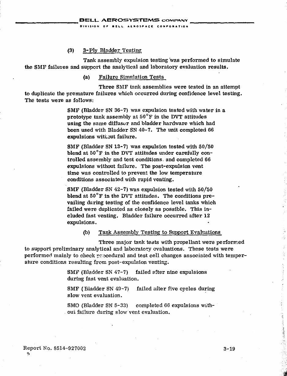
__________ BELL AEROSYSTEMS COMPANY _________ _
O"IVI$ION OF .£I..L At.ROSPACr: CORPO".TION
(3) 3-Ply Bllldder Testint';.
Tank assembly expulsion testing ",vas performed to simulate the SMF failul'es and support the analytical and laboratory evaluation results.
(a) Failure Simulation Tests
Three Sl\IF tank assemblies were tested in an attempt to duplicate the premature failures which occurred during confidence level testing. The tests were as follows:
SMF (Bladder SN 36-7) was expulsion tested with water in a prototype tank assembly at 50°F in the DVT attitudes using the same diffus<.lr and bladder hardware which had been used with Bladder SN 40-7. The unit completed 66 expulsions wittout failure.
SMF (Bladder SN 13-7) was expulsion t:ested with 50/50 blend at 50 OF in the DVT attitudes under carefully controlled assembly and test conditions. and completed 66 expulsions without failure. The post-expulsion vent· time was controlled to prevent the low temperature conditions associated with rapid venting.
SMF (Bladder SN 42-7) was expulsion tested with 50/50 blend at 50°F in the DVT attitudes. The conditions prevailing during testing of the confidence level tanks which failed were duplicated as closely as possible. This included fast venting. Bladder failure occurred after 12 expulsions.
(b) Tank Assembly Testing to Support Evaluations
Three major tank teots with propellant were performed to support preiiminary analytical and laboratory '~valuations. These tests were performea mainly to check p-r,lcedural and test cell changes associated with temperature conditions resulting from post-expulsion venting.
SM:e (Bladder SN 47-7) failed aft.er nine expulSions during fast vent evaluation.
SMF (Bladder SN 49-7) failed after five cycles during slow v£nt evaluation.
SMO (Bladder SN 5-33) completed 66 expulSions with. out failure during slow vent evaluation.
Report No. 8514-927002 ~
3-19
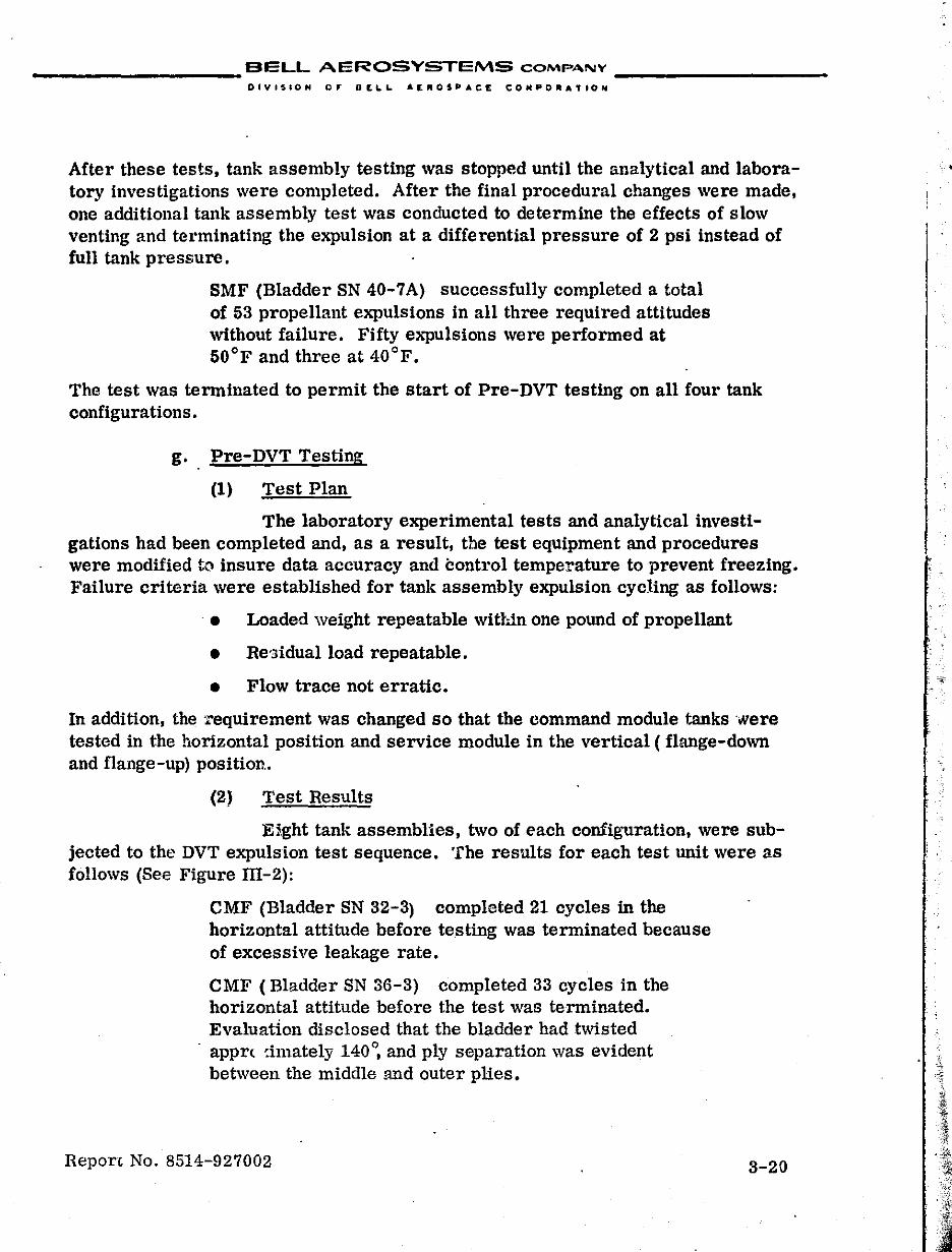
__________ BELL AEROSYSTEMS COMPANY _________ _
OIVISION 0,. Dtl..L. A~"OSP.CE COMPO_ATtON
After these tests, tank assembly testing was stopped until the analytical and laboratory investigations were completed. After the final procedural changes were made, one additional tank assembly test was conducted to determine the effects of slow venting and terminating the expulsion at a differential pressure of 2 psi instead of full tank pressure.
SMF (Bladder SN 40-7A) successfully completed a total of 53 propellant expulsions in all three required attitudes without failure. Fifty expulsions were performed at 50°F and three at 40°F.
The test was terminated to permit the start of Pre-DVT testing on all four tank configurations.
g. Pre-DVT Testing
(1) Test Plan
The laboratory experimental tests and analytical investigations had been completed and, as a result, the test eqUipment and procedures were modified to insure data accuracy and control temperature to prevent freezing. Failure criteria were established for tank assembly expulsion cycling as follows:
. • Loaded weight repeatable within one pound of propellant
• Re'3idualload repeatable.
• Flow trace not erratic.
In addition, the xequirement was changed so that the command module tanks were tested in the horizontal position and service module in the vertical ( flange-down and flange-up) position..
(2) Test Results
Eight tank assemblies, two of each configuration, were subjected to the DVT expulsion test sequence. The results for each test unit were as follows (See Figure Ill-2):
CMF (Bladder SN 32-3) completed 21 cycles in the horizontal attitude before testing was terminated because of excessive leakage rate.
CMF (Bladder SN 36-3) completed 33 cycles in the horizontal attitude before the test was terminated. Evaluation disclosed that the bladder had twisted
- appr( cimately 140°, and ply separation was evident between the middle lUld outer plies.
Report No. 8514-927002 3-20
.~
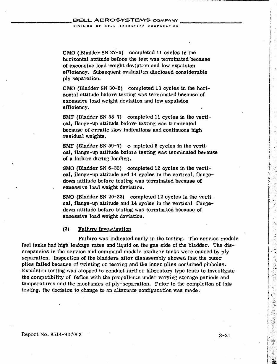
__________ BELL AEROSYSTEMS COMPANY _________ _
UIVI$IQN or DELL AI[fIII0SPAct C.ORPOAATlON
CMO (Bladder SN 27-5) completed 11 cycles in the horizontal attitude before the test was terminated because of excessive load weight devial,;i>n and low exp .. lsion efficiency. Subsequent evaluatbn disclosed considerable ply separation.
CMO (Bladder SN 30-5) completed 13 cycles in the horizontal attitude before testing was terminvied because of excessive load weight deviation and low expulsion efficiency.
SMF (Bladder SN 58-7) completed 11 cycles in the vertical, flange-up attitude before testing was terminated because of erratic flow Indications and continu(lus high residual weights.
SMF (Bladder SN 59-7) c, mpleted 5 cycles in the vertical. flange-up attitude before te!>ting was terminated because of a failure during loading.
SMO (Bladder SN 6-33) completed 12 cycles in the vertical. flange-up attitude and 14 cycl~s in the vertical, flange-
. down attitude before testing was terminated because of excessive load weight deviation.
SMO (Bladder SN 20-33) completed 12 cycles in the vertical, flange-up attitude and 14 cycles in the vertical flangedown attitude before testing was terminated because of excessive load weight deviation.
(3) Failure Investigation
Failure was indicated early in the testing. The service module fuel tanks had high leakage rates and liquid on the gas side of t~e bladder. The discrepancies in the service and command module oxidizer tanks were caused by ply separation. Inspection of the bladders after disassembly showed that the outer plies failed because of twisting or tearing and the inner plies contained pinholes. Expulsion testing was stopped to conduct further U·.boratory type tests to investigate the compatibility of Teflon with the propellants under varying storage periods and temperatures and the mechanics of ply-separation. Prior to the completion of this testing, the decision to change to an alternate configuration was made.
Report No. 8514-927002 3-21
! r !
I r f
r
; I i ; , I
i I
I.:· f J' " I . I
I f
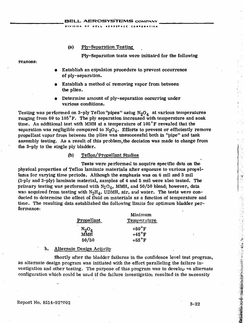
__________ BELL AEROSYSTEMS COMPANY _________ _
O_VUION or DELL. A£ROSPAce CORPORATION
(a) Ply-Separation Testing
Ply-Separation tests were initiat('d for the following reasons:
• Establish an e"l>ulsion procedure to prevent occurrence of ply-separation.
• Establish a method of removing vapor from between the plies.
• Determine amount of ply-separation occurring under various conditions.
Testing was pc rformed on 3-ply Teflon "pipes" using N20 4 at various temperatures .ranging from 60 to 105°F. The ply separation increased with temperature and soak time. An additional test with MMH at a temperature of 105°F revealed that the separation was negligible compared to N204' Efforts to prevent or effiCiently remove propellant vapor from between the plies was unsuccessful both in "pipe" and tank assembly testing. As a result of this problem,the decision was made to change from the 3-ply to the single ply bladder.
(b) Teflon/Propellant Studies
Tests were performed to acquire spe"tfic data on the physical properties of Teflon laminate materials after exposUl'e to various propellams for varying time periods. Although the emphasis wa.s on 6 mil and 3 mil (I-ply and 3-ply) laminate mate~ial. samples of 4 and 5 mil were also tested. The primary testing was performed with NZ04. MMH. and 50/50 blend; however. data war; acquired from testing with N2H4' UDMH. air. and water. The tests were conducted to determine the effect of fluid on materials as a function of temperature and time. The resulting data established the following limits foI' optimum bladder performance:
Propellant
N20 4 MMH 50/50
h. Alternate Design Activi~
Minimum Temrer,lture
+50 o F +45°F +!'i5 OF
Shortly after the bladder failures in the confidence level test program. an alternate design program was initiated with the effort paralleling the failure investigRtion and other testing. The purpose of this program was to develoiJ 'In alternate configuration which could be us",d if the failure investigatioll resulted in the n~cessity
Report No. 8514-927002 3-22
-~
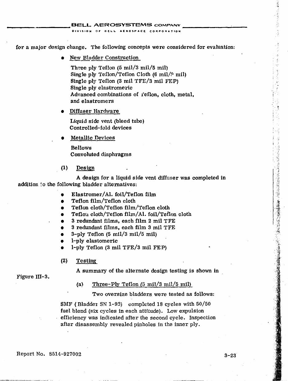
_________ BELL AEROSYSTEMS COMPANY _______ ~ __
OIVI5,ON OF PEL. ... AER05PACE CORPORATION
for a major design change. The following concepts were considered for evaluation:
• New Bladder Construction
Three ply Teflon (5 mil/a millS mil) Single ply Teflon/Teflon Cloth (6 mil/P mil) Single ply Teflon (S mil TFE/S mil FEP) Single ply elastromeric Advanced combinations of l'eflon, cloth, metal, and elastromers
• DiffuserHardware
Liquid side vent (bleed tube) Controlled-fold devices
• Metallic Devices
Bellows Convoluted diaphragms
(1) Design
A design for a liquid side vent diffuser was completed in addition to the following bladder alternatives:
Figure Ill-3.
• Elastromer/ AI. foil/Teflon film • Teflon film/Teflon cloth • Teflon cloth/Teflon film/Teflon cloth • Tefloi.l cloth/Teflon film/AI. foil/Teflon cloth • 3 redundant films, each film 2 mil TFE • 3 redundant films, each film 3 mil TFE • 3-ply Teflon (5 millS mil/5 mil) • I-ply elastomeric • I-ply Teflon (3 mil TFE/a mil FEP)
(2) Testing
A summary of the alternate design testing is shown in
(a) Three-Ply Teflon (5 mil!3 millS mil)
Two oversize bladders were tested as follows:
SMF (Bladder SN 1-93) completed 18 cycles with SO/50 fuel blend (six cycles in each attHude). Low expulsion efficiency was indicated after the second cycle. Inspection after disassembly revealed pinholes in the inner ply.
Report No. 8514-927002 3-23
• !
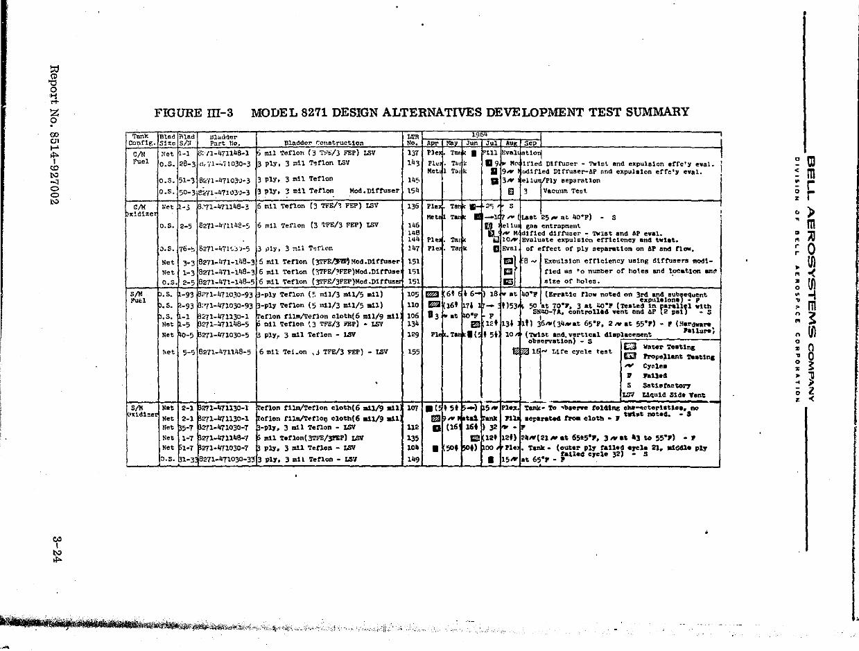
~ "0 o '1 .... Z o
FIGURE m-3 MODEL 8271 DESIGN ALTERNATIVES DEVELOPMENT TEST SUMMARY . 00 v' ..... t to I.'-' -:J o o I>:>
Cf I.'-'
"'"
Ta.!l'k. Conr1g.
elM fuel
elM xld1%e
81M J'uel
SIll }~1d1::et
Ul&.d :Mlad l.il .. dller S!ze SF,i Part Tlo,
~et I-I 1'5: (1-47114B-l
O.S. 28-3 (Ir71-"710,30-3
0.5, 51-3 BF;l-471 03'J'" 3
O.S, 50-3 e~"{l-47103'J-3
I:et ~-3 fS.'71-47114B- 3
o.s. 2-5 E271-U'1'1l4!!-,
J.S. 76",~ 6271-471 s:' "j-5
Net 3-3 B271-471-148-3 N'!t 1-3 8271-471-14B-3 O.S. 2-5 8271-471-14B-5
.s. -93 ~'71-471030-93
. s . . -93 P:'11- 471030-93
.s. -1 ~~1-471130-1 Net -5 271-47114B-5 Net W-S ~2'rl-471030-5
.. t 5-5 B271-471148-5
Net 2-1 271-471130-1 Ne. 2-1 271-471130-1 net 5-7 271-471030-7 Net 1-1 271-471148-1 Ne, 1-7 271-471030-7
0.8. 1-3 13271-471030-33
l1rR Bladdc1' Conetructlon No.
j mil Teflon !3 T!~t:/3 FEP) LSV 137 3 ply, 3 mil T~rlon LSV 143
3 ply, 3 mIl Teflon 1~5
·3 ply, 3 mil Tenon Mod. Dl truser 154
6 a11 Teflon (3 TFE/~ FEP) LSV 136
6 mil Teflon (3 1?E/3 FEP) LSV 146 '14B ,"4
3 jlly, 3 ~!l T<:lfi(lr. 141
5 mil Tetlon (J'rFEI.*"!P) Mod .Dlfruser 151 6 mil Terlcm (3TPE/?FEP)Mod.Dlrfuse 151 6 mil Teflon {3TFE/3FEP)Mod.Dlftus~ 151
:-ply Teflon (~ mill) mll/5 m11) 105
-ply Terlon (5 mi1/3 mi1/5 mil) 110
etlon tl~erlon eloth(6 ml1/9 mil 106 . all Tetlon t3 TFE/3 PEP) • LSV 134
;,'j ply f 3 1Il11 Teflon • LSV 129
6 mil Tei_on \J TFE/3 PEP) - LSV 155
. etlon tl~erlon cloth(6 adl/9 .tl 107 arlon rllm1Terlo~ clotb(6 a11/9 all -PI,.. 3 litH '!'etlon • LSV 112
mil ororlon( 3TFE/3I'EP) LSV 135 ply. 3 mIl Teflon - LSII 10_
3 PI)'". 3 1Il11 Teflon - LS'l 149
~'tltn ir'1iil'b __ UM!tr'!i\jI,;~'f~~''''*",''~''''''';'.''"i~.,,,,,, cO"" _,h ~ " ~",","
.-
A r Pl ••
Pl!: Met-
PIe
Met
PI., Pl.
1m IiJl'JI 83
PI
.( FZiI a
•
19"" ". Jun Jul Au Scp I
• Ta I 111 'val 0"01 I • Ttl k 119 .. Mo HIed DHfuoer ... Twtat and expuhllon errc':y e'¥al~ I 1 Ttilk D 9'" tJd1fled Dtfruser-AP ond expulsion erre', cval.
II 3'"' ellun/Ply eeparatlon
0 3 Vacuum Teat
T. '~ ::'1 S I
T .. -1 7"" Uet 25", at 4o-F) ... S , f~
ellu gaa entrapment I
NM dlt1ed d1fruocr ... 'l'W'lDt and !if e.al. • To 10 .... Evaluate expulsion eftlciency and t.l.t • • Ta k II Eval of effect of ply separation on AP end flow.
I!llt 8_ ExDulslon efflclency usln~ dtffusers modl-
:J fled QS to n~ber of holes and l~c.tlan en~ elze of holes.
6' • 6~ ) IB " at 4O·P {Erratic flow noted on 3r4 an4 eub,equent
16' 7' 1)53 expulalona .. I' - 59 at 10·.. 3 at ~.p (teate4 In ferall,l with
i- at o·p r p SNqo-7A. controll.4 vent and ~p 2 pal - S , B!J 12' 131 "1 36"'(34",at 65·p. 2"'0' 55'P) - P (Hardware
• Tat I( , 5' 10'" (nr1:lt and. verotlcal 4iaplaceIMnt .allure; obeervatlon) - S £:J T"" .... '.' '" --~ !rop.~1&nt ~atln.
,., Cyr:lea ~ ft11e4 S SaUaraetoZ07
LSV LIqUid Sl~. Vent ~
-) 151 5'" Pl •• 'tank- 'ro ''''.ern to14tn,s cIW ..... eteroUtlo •• no
(;6' tal ~ank PIli .eperated troa cloth .. ., twi.t noted. - a 16. )32 "'- iF Ii\! 121 12') 211"'(21",.t 65>5·P, 3 ..... '3 to 55·P) - P
50' 501) poo Pl. • Tank. (outer P17 raned -reI_ 21. al641. pI,.
• 15# talled c7cle 32) - S
at 65·' • p " --
•
•
~ OJ :: m ~ r ~ r " ) ~ m .. Al ~ 0 ,. Ul ~ -< ; ~ : m ~ ~
Ul n o ~ 0 ~ 0 ~ ~ : } o l z < I
I f
,
I __________ BELL A'EROSYSTEMS COMPANY _________ _
DIVISION OF BEL~ AEAOSPA.;E COfl~·u:tATION
S'HF (Bladder SN 2-93) completed 53 cycles with 50/50 fuel blend without failure. The first 5'0 cycles were conducted at +50 OF and the last three at +40 OF. Vent cycle was controlled to limit temperature drop and expulsion terminated at a f':, P of 2 pSi. This bladder was tested in parallel with SN 40-7A.
These results supported by flex and ply separation tests on "pipe" sections indicated that this configuration had no apparent advantage over the 3-ply, 3 mil construction.
as follows:
(b) Teflon Film/Teflon Cloth (6 I:1i1/9 mil)
Two, Teflon film/Teflon cloth bladders were tested
SMF (Bladder SN 1-1) oversize bladder failed after third e}.."Pulsion with 50/50 fuel blend. Inspection revealed a small crack in the inner film.
SMO (Bladder SN 2-1) completed 15 water expulsions in the plexiglaR1'l tank as a net size bladder. Five cycles were conducted in each attitude to observe folding. There was no evidence of tWisting. The bladder was then installed in the metal tank and completed nine N204 expulsions. Inspection revealed leakage at a seam.
These results coupled with the informathm acquired from testing three "pipe" sections indicated that this construction was not adequate.
(c) Elastomeric Bladders
A single-ply elastomeric bladder development program was established and fabrication was initiated at the following three vendors:
Stillman Rubber Company Thiokol Chemical Corp., Reaction Motors Div. Dilectrix Corp.
Specimens of the elastomeric compcumio were tested for compatibility in 50/50 blend, MMH, and N204 concurrently with the fabrication development. The compnunds tested were as follows:
Report No. 8514-92'{002
SR617··75 (Stillman) SR634-70 (Stillman) EPR132 (Thiokol) Parco 823-70 (Dilectrix)
3-25
--~
.--:,<
__________ BELL AERC>SYSTEMS COM~'AN'I __________ ,
DIVISION OF' OEL~. AEfi1:0SPACE COAPOR'\TltN
Numerous delays in the planned program resulted from fabrication problems. Stillman used the core molding technique for bladder fabrication and several tooling problcms arose. A total of 25 bladders were fabricated. Threc of these were shipped to Bell; however, none were suitable for testing. In addition to the core molding development, Stillman fabricated samples to evaluate the vacuum bagmolding process. Dilectrix effort consisted of the development of a vacuum bagmolding process using Parro 823-70 Butyl compound. A total of three bladders w~re fabricated. The last one was shipped to Bell but was not tested. Thiokol effort was limited to fabrication of seamed specimens for bonding compatibility testing. The elastomeric program was stopped because of the decision to use the single-ply Teflon bladders.
(d) Liquid Side Vent (Bleed Tube) Diffuser
Service module testing with 3-ply, 3 mil bladders was performed to evaluate twist and vertical displacement of the bladder using diffusers modified to include the bleed tube. Bladders were tested in both the oversize and net size configuration as discussed as follows:
SMO (Bladder SN 61-7): Anet size bladder assembled with a modified diffuser tube and a liquid side vent completed 100 vertical water expulsions (50 flange-up, 50 flangedown). The two outer plies had failed prior to the 33rd cycle, but testing was continued to observe twist.
SMO (Bladder SN 35-7): A net size bladder assembled with liquid side vent diffuser failed after 32 vertical water expulsions (16 flange-up, 16 flange-down) were completed.
SMF (Bladder SN 40-5): A net size bladder with a liqUid side vent was tested to observe filling procedure and bladder behavior. This unit completed five flange-up. and five flange-down water cycles in a plexiglass tank. The fill procedure was satisfactory and measured maximum twist was 3/8-inch clockwise and twist following the 10th expulsion was 1/4-inch clockwise.
SMO (Bladder SN 31-33): Anoversize bladder completed15 propellant expUlsions to compare with liquid! side vent performance of a 3-ply bladder with a single-ply bladder. Results showed that the loaded weight could not be reproduced from cycle to cycle with the three-ply bladder. The outer ply tore around the top spherical radius.
Report No. 8514-927002 3-26
, , . I
i
= "
.'
__________ BELL AEROSYSTEMS COMPANY _________ _
Dlvt;ION OF BELL. AER05P_CE CORPORATION
This testing successfully demonstrated the usefulness of the liquid bleed tube for the service module configulation. This concept was further proven during testing with the bingle-ply bladder.
Command module expulsion tests using 3-ply and single-ply bladders were performed to estl'lblish servicing procedures and evaluaw performance characteristics of the liquid side vent diffuser for the command module configuration. The results are as follows:
CMF (Bladder SN 1-1): 'Ibis single-ply net size bladder was assemhled with a liqUid side vent diffuser tube. The bladder was tested in the plexiglass tank to develop a procedure for horizontal loading with the bladder expanded with gas that is vented during load. The tests were unsuccessful. Additional tests WI)re conducted using standard evacuation loading procedure & .. ld e:c:pelling to determine b. P characteristics of the new diffuser tube.
CMO (Bladder SN 1-3): This net size Single-ply 6 mil bladder was assembled in a plexiglass tank with a liqUid side vent and cycled for the purpose of measuring bladder twist. Twenty-five cycles were completed with water as the test fluid in a horizontal attitude. The maximum measured twist on the first cycle was 1-3/S inches. The measured. twist following the 25th expulsion was l/S'-inch in a counterclockwise direction. This bladder was then assembled into a metal tank and subjected to an additional 107 water cycles (the last 25 at 40°F) without failure.
CMF (Bladder SN 28-3): Water expulsion tests with an oversize 3-ply bladder and LSV diffuser (holes in cone) were conducted to compare twist and expulsion efficiency with standard diffuser tube data. Nine cycles were completed in the plexiglass tank with the maximum twist being 11 inches. The bladder assembly was installed in the metal tank and nine cycles were completed to check t;P and expulsion efficiency. The b. P was reproducible with minimum expulsion efficiency at b. P of 2 psi being 96.6 %.
Report No. 8514-92.7002 3-27
..
________ -.;._BELL AEROSYSTEMS COMPA.NY _________ _
DIVISION ",. BELL A£IIIIOSPACE CO.POAATION
CMO (Bladder SN 2-5): 'rhis single-ply oversize bladder was subjected to a series of the followi,ng three separate tests:
The first test was to evaluate the effect of helium on gas entrapment with a single ply bladder. This test was performed for comparison with a Similar test on a 3-ply oversize bladder (CMF Bladder SN 51-3). This bladder had been tested to evaluate the effect of helium on ply separation and gas entrapment with a 3-ply, oversize bladder in MIVlH. It was found by flowing through a gas trap that the permeation of helium prior to the bladder fill cycle contributes to gas trapped in bladder.
The second test consisted of water expulsion tests to study the effect of flowing through the diffuser cones only (holes in tube were masked). Nine cycles were completed in (tlis condition and the results showed that the amount of twist wa::; reduced by expelling through the holes in the cones, but the 6 P was much greater (5 psi vs 1 psi).
The third test consisted of water expulsion tests to study expulsion eff:ciency an.d twist using an oversize single ply bladder with the liqUid side vent diffuser tube. Ten expulsions were completed in the plexigll.'.ss tank. Twist and 6 P were recorded on the firs~ nine cycles. On the 10th cycle an air bubble was intentionally introduced with the liqUid load to tcst flow stability. The flow trace did not become erratic until approximately midway through the expulsion.
CMO (Bladder SN 76-5): This 3-ply oversize bladder was subjected to water expulsion tests in the plexiglass tank with a .standard diffuser tube to evaluate the effect of ply separation on 6 P and flow. Gas was injected between plies prior to the expulsions. The results showed that with a small amount of gas (55 in.3) between plies there was little effect on expulsion efficiency; however, with a large amount of gas (308 in.3) between plies, there was a decided decrease in expulsion efficiency.
No additional command module testing was performed to evaluate the liquid side vent diffuser at this time. Additional single-ply testing was performed with standard diffusers.
Report No. 8514-927002 3-28 i ! f ! . t f I !
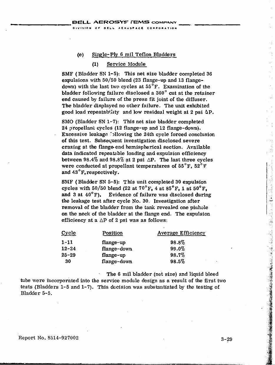
7
BELL AEROSY~ ,EMS COMPANY --------- -, OlVISION OF flt:~L. "£A,",S,"ACIt COMPO_.TION
(e) Single-Ply 6 mil Teflon Bladders
(1) Service Module
SMF (Bladder SN 1-5): This net size bladder completed 36 expulsions with 50/50 blend (23 flange-up and 13 flangedown) with the last two cycles at 55 of. Examination of the bladder following failure disclosed a 360 0 cut at the retainer end caused by failure of the press fit joint of the diffuser. The bladder displayed no other failure. The unit exhibited good load repeatabHity and low residual weight at 2 psi ~P.
SMO (Bladder SN 1-7): This net size bladder completed 24 propellant cycles (12 flange-up and 12 flange-down). Excessive leakag,~ ~)llowing the 24th cycle forced conclusion of this test. Subsetiuent investigation disclosed severe crazing at the flange. end hemispherical section. Available data indicated repeautble loading and expulsion efficiency between 98.4% and 98.8% :;tt 2 psi liP. The last three cycles were conducted at propellant temperatures of 55°F. 52°", and 43°F,respectively.
SMF (Bladder SN 5-5): This unit completed 30 expulsion cycles with 50/50 blend (22 at 70°F, 4 at 85°F, 1 at 50°F, and 3 at 40°F). Evidence of failure was disclosed during the leakage test after cycle No. 30, Investigation after removal of the bladder from the tank revealfld one pinhole on the neck of the bladder at the flange end. The expulsion efficiency at a t,p of 2 psi was as follows:
Cycle Position Average Efficiency
1-11 flange-up 98.8% 12-24 flange-down 99.0% 25-29 flange-up 98.7%
30 flange-down 98.5%
The 6 mil bladder (net size) and liquid bleed tube were incorporated into the service module design as a result of the first two tests (Bladders 1-5 and 1-7). This decision was substantiated by the testing of Bladder 5-5.
Report No. 8514-927002 3-29
,
,'·-:f
"
•........• ;.' .
A
__________ RELL. AEROSYSTEMS COMPANY _________ _
". -..
OlvaSION 0,. 8~L.L. AERO$PACE CORPOIllATI~N
(2) Command Module
Three single-ply bladders had been tested previously as part,of the command module liquid side vent diffuser testing. In order to define the diffuser assembly and bladder configuration for the command module unitb, a test series was conducted to measure b.P versus expulsion efficiency. The
. testing was done in a command module oxidizer tank, using both full-size and over-size single-ply,6 mil Teflon (TFE/FE~ bladders. Three bladders (SN 3-3, 1-3, and 2-5, completed a total of 68 water expulsions using four types of diffuser configurations. These tests indicated that th., optimum technical eOiuiguration consists of diffuser hardware having holes in both the flange and retainer cones. However, to permit the reworking of a considerable amount of existing hardware, a configuration having holes in the retainer cone only was selected. To make this compromise configuration acceptable from the standpoint of repeatability of the 6. P versus expulsion efficiency curve, the use of an oversized bladder was reqUired. Therefore,an oversized single. ply , 6 mil bladder and hardware having 216 holes in the retainer cone was selected as the configuration for the command module tanks. In addition, a test series was conducted with MMH in a command module fuel tank (Bladder SN 50-3) to evaluate methods and establish procedures for pulling a vacuum at 28 inches of mercury withollt letting the bladder and associated hardware temperature drop below +40 oF.
i. Single-Plv Teflon Bladder Development
(1) Dynamic Testing
A new dynamic test program was required to demonstrate the following capabilities:
• New acceleration-expulsion requirement for comm!Uld module tankage
• Slosh with propellant
• Slosh and vibration of single-ply bladder
• Vibration of oversize bladder
• Vibration of liqUid side vent diffuser
(a) Acceleration-Expulsion
A CMF tank assembly with an oversize bladder (SN 44-3), and a CMO tank assembly with an oversize bladder (SN 46-5) were tested to evaluate the expulsion capability of command module tanks during acceleration. The tanks
Report No. 8514-927002 3-30
. '
:Jl : .. t ' .. '
, ... '.W11 .1
......... ' ",,",' ' ........ , __ ~ ... h_' " ..... _,_' ... ' ............ '~.~ .... b ...... ' ... · .. W ... -____ .... ffl ........ ' ... a * .............. ·-t_ ............. n .... · _,_of ---..."' ....... W*_· ...... ' c ....... "'.!~ ........ ' ....... --....:....,..-~ _ , ", ._,...;..;1
__________ BELL AEROSYSTEMS COMH'N'V _________ _
.slift "
DIVISION OF' PEI..L. AEROSPACE CORPORATION
were subjected to a 20 g acceleration force in the X-axis (longitudinal) with the expulsion tube facing the center of rotation. The tanks were loaded to more than 75% of propellant capacity with simulated propellants and the gas side was pressurizeJ to 287 ~g psig with helium. The liquids were expelled at specified flow rates in a series of eow bursts which were terminated at 60, 40, and 25 percent of maximum propellant capacity and when the pressure differential between the gas and the liquid sides, due to eXpulsion, reached 2 psig. Both bladders were intact after the testing.
A CMO tank with a Single-ply bladder (SN 7-5) was subjected to a 28 g acceleration force. The acceleration force was appUed perpen-1icular to the longitudinal X-axis for a period of 5 minutes. The tank assembly was then tested to evaluate the expulsion capability of the command module tanks while being subjected to a 20 g acceleration force perpendicular to the longitudinal X-axis. The outlet port faced forward with respect to the direction of rotation and the outlet tube pOinted toward the center of rotation. The expulsion was accomplished in three flow bursts which were terminated at 58.5, 38, and 21.2% of propellant capacity. The pressure differential following the third flow burst was 4.68 psi. The test was completed without damage to the tank structure or the bladder. This tank attituc1e was found to be more detrimental to the performance of the unit than when the 2\1 g acceleration force was applied along the X-axis.
(b) Slosh
Two service module tanks with 3-ply oversize bladders were tested to evaluate slosh with propellant. The results were a" follows:
SMO (Bladder SN 22-33): The unit was loaded to 1/3 capacity with nitrogen tetroxide and the gas side pressurized to 25 psig with helium. The tank was positioned with the diffuser tube horizontal and subjected to 500 slo:;;h cycles in the direction of the diffuser tube at 0,94 eps \'\ith 2.41 inches peak-tO-peak input. The tank was t.hen subjected to 500 slosh cycles at 2.0 cps with 0.53 inch peak-to-peak input in a direction perpendicUlar to the diffuser tube.
SMF (Bladder SN 46-7): The unit was loaded to 1/3 capacity with 50/50 blend and pressurized to 25 psig with helium. The tank was subjected to 500 slosh cycles in the direction of the diffuser tube at 0.95 cps with 2.36 inches peak-to-peak input. The tank was then repositioned so that the diffuser tube was vertical and subjected to 500 slosh cycles at 1.90 cps with 0.59 inch peak-to-peak input in a direction perpendicular to the diffuser tube.
Report No. 8514-927002 3-31
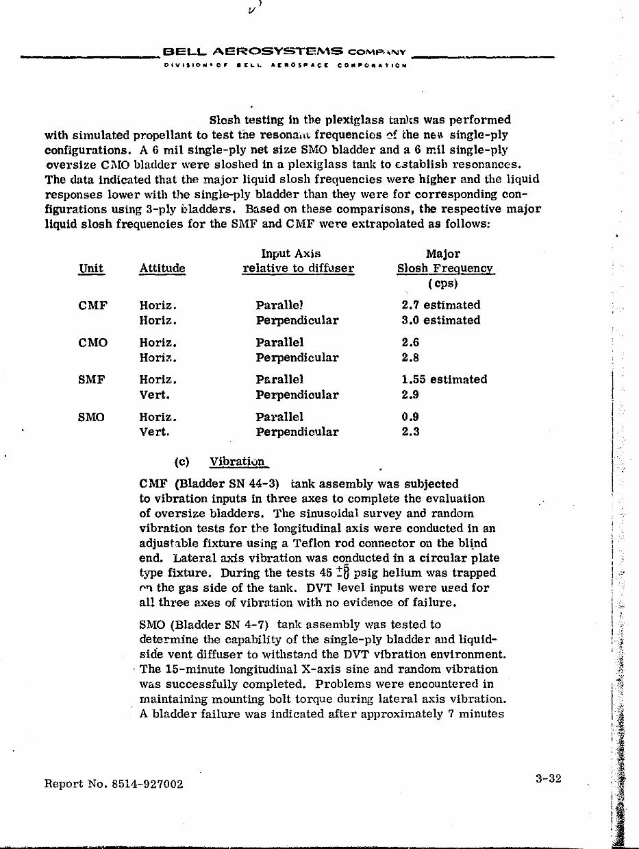
) v
... __________ BELL AEROSY~..,_E""S COMP,.NY ___ ~ _____ _
Slosh testing in the plexiglass tawes was performed with simulated propellant to test the resona,lt frequencies 0! the nH single-ply configurations. A 6 mil single-ply net size SMO bladder and a 6 mil single-ply oversize Cl\IO bladder were sloshed in a plexiglass tank to £,stablish resonances. The data indicated that the major liquid slosh frequencies were higher and the liquid responses lower with the single-ply bladder than they were for corresponding configurations using 3-ply bladders. Based on these comparisons, the respective major liquid slosh frequencies for the SMF and CMF were extrapolated as follows:
CMF
CMO
SMF
SMO
Input Axis Malor Attitude relative to diffuser Slosh Freguency
( cps)
Horiz. ParalleJ 2.7 estimated Horiz. Perpendicular 3.0 estimated
Horiz. Parallel 2.6 Horiz. Perpendicular 2.8
Horiz. Parallel 1.55 estimated vert. Perpendicular 2.9
Horiz. Pal"allel 0.9 Vert. Perpendicular 2.3
(c) Vibration
CMF (Bladder SN 44-3) tank assembly was subjected to vibration inputs in three axes to complete the evaluation of oversize bladders. The sinusoidal survey and random vibration tests for the longitudinal axis were conducted in an adjustable fixture using a Teflon rod connector on the bl~nd end. Lateral axis vibration was conducted in a circular plate type fixture. During the tests 45 :!:8 psig helium was trapped (''1 the gas side of the tank. DVT level inputs were used for all three axes of vibration with no evidence of failure.
SMO (Bladder SN 4-7) tank assembly was tested to determine the capability of the Single-ply bladder and liquidside vent diffuser to withstand the DVT vibration environment .
. The 15-minute longitudinal X-axis sine and random vibration was successfully completed. Problems were encountered in maintaining mounting bolt torque during lateral axis vibration. A bladder failure was indicated after apprOximately 7 minutes
Report No. 8514-927002 3-32
,--.
I I "
I" i I
I
I "
, .
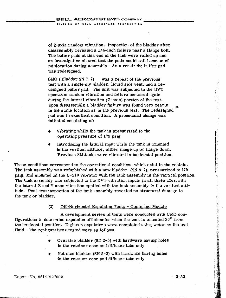
____________ BELL AEROSYSTEMS COMPA.NY _________ _
OIVISoION OF O£~L. AEROSPAC£ CC"IIIIPORATION
of Z-axis random vibration. Inspectioll of the bladder after disassembly revealed a 1/4-inch failure near a flange bolt. The buffer pads at this end of the tank were rolled up and an investigation showed that the pads could roll because of mislocation during assembly. As a result the buffer pad was redesigned.
SMO (Bladder SN 7-7) was a repeat of the previous test with a single-ply bladder, liquid side vent, and a redesigned buffer pad. The unit wat" subjected to the DVT spectrum random vibration and failure occurred again during the lateral vibraticll (Z-axis) portion of the test. Upon disassembly, a bladder failure was found very nearly. :,. in the same location as in the previous test. The redesigned pad was in excellent condition. A procedural change was initiated consisting of:
• Vibrating while the tank is pressurized tr> the operating pressure of 179 psig
• IntroduCing the lateral input while the tank is oriented in the vertical attitude, either flange-up or flange-down. Previous SM .tanks were vibrated in horizontal position.
These conditions correspond to the operational conditions- which exist in the vehicle. The tank assembly was refurbished with a new bladder (SN 8-7), pressurized to 179 psig, and mounted on the C-210 vibrator with the tank assembly in the vertical pOSition. The tank assembly was subjected to the DVT vibration inputs ~n all three axes, with the lateral Z and Y axes vibration applied with the tank assembly jn the vertical attitude. Post-test inspection of the tank assembly revealed no structural d~age to the tank or bladder.
(2) Off-Horizontal Expulsion Tests - Command Module
A development series of tests were conducted with CMO configurations to determine expulsion efficiencies when the tank is oriented 30° from the horizont?,l position. EighteLn expulsions were completed using water as the test fluid. The 'Jonfigurations tested were as follows:
• Oversize bladder (Sf!: 2-5) with hardware having holes in the retainer cone and diffuser tube only
• Net size bladder (SN 5-3) with hard\vare having holes in the retainer cone and diffuser tube ('nly
Repor' "l"o. 8514-927002 3-33
..
I I
I L r
, I '
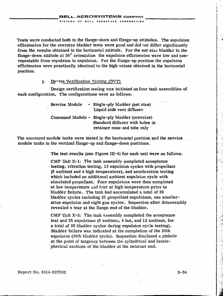
____________ BELL AEROSYSTEMS COMPA.NV _________ _
DIVISION OF DELL AEROSPACE CORPORATION
Tests were conducted both in the flange-down and flange-up attitudes. The e>'"pulsion efficiencies for the oversize bladder tests were good and did 110t differ significantly from the results obtained in the horizontal attitude. For the net siz0 bladder in the flange-down attitude at 30° orientation the expulsion efficiencies were low and nonrepeatable from expulsion to expulsion. For the flange-up position the expulsion efficiencies were practically identical to the high values obtained in the horizontal position.
j. De"ilJn Verification Testing (DVT)
Design verification testing was initiated on four tank assemblies of each configuration. The configurations were as follows:
Service Module - Single-ply bladder (net size) Liquid side vent diffuser
Command Module - Single-ply bladder (oversize) Standard diffuser with holes in retain~r cone and tube only
The command module tanks were tested in the horizontal position and the service module tanks in the vertical flange-up and flange-down positions.
The test results (see Figure 1II-4) for each unit were as follows:
CMF Unit X-1: The tank assembly completed acceptance testing, vibration testing, 13 expulsion cycles with propellant (9 ambient and 4 high temperature), and acceleration testing which included an additional ambient expulsion cycle with simulated propellant. Four expulsions were then completed at low temperature lLlld four at high temperature prior to bladder failure. The tank had ac(',umulated a total of 30 bladder cycles including 21 propellant expulsions, one acceleraHon expulsion and eight gas cycles. Inspection after disassembly revealed a tear at the flange end of the bladder.
CMF Unit X-2: The tank ll.E;sembly completed the acceptance test and 25 expulsions (9 ambien~, 4 hot, and 12 ambient, for a total of 25 bladder cycles during expulsion cycle testing). Bladder failure was indicated at the completion of the 25th expulsion (30th bladder cycle). Inspection disclosed a pinhole at the point of tangency between the cylindrical and hemispherical sections of the bladder at the retainer end.
Report No. 8514-927002 3-34
•
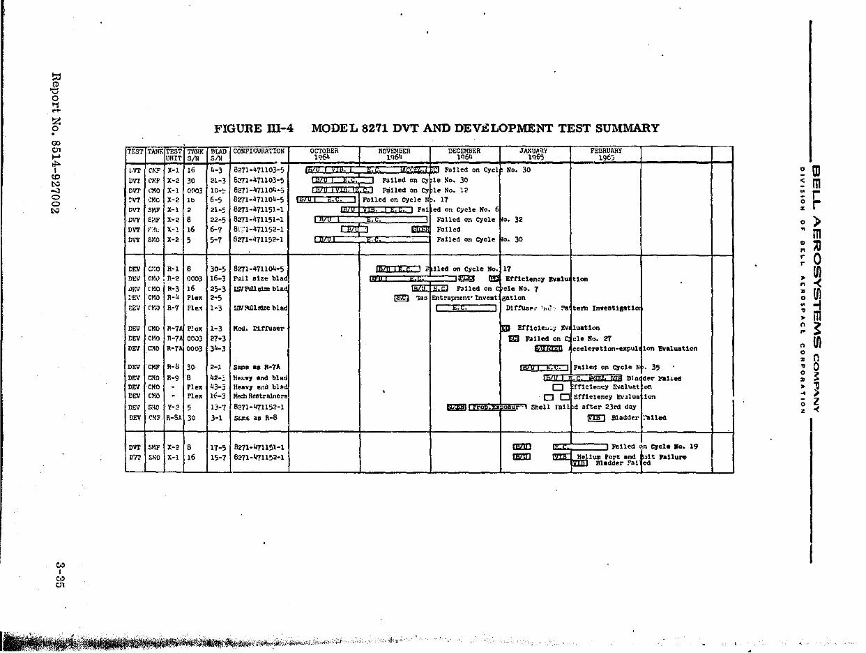
~ 'tl o 'i .... ~ . 00 -" t-' tl>I
to t..:> -'l o o t..:>
c.o I
'" tJ1
FIGURE m-4
TESTITANKfTESTI'I'AtlK I "LAD UNIT Sill Sill
LVT Cl\P X-I 16 4-3
DVT C~!F X-2 30 21-3 DV'I' (14;0 X-I OflO; lO .. ~
~VT GMc X-2 Ib 6-5 DVT SMF X-I 2 21 .. 5-DVT St{F X-2 8 22-5
OVT f,~t.i X-I 16 6-7
DVT 81'00 X-2 5 5-7
DEY el-:O I R-l 8 30-5 Dl-."V CI>ll.l ~ R-2 0003 16-3
"EV ['MO I R-3)6 25-3 :.£v eKO ~-4 Plex 2-5
~v rNa RooT Ple~ 1-3
DEY I eMO I R-7j Pl.'/1-3 DEY CHo R-7 00J3 27-3 DEY 0010 R-7 0003 34-3
DEY eMF R-8 30 2-) DEY eMO R-9 8 42-:' DEV eKo Plex 43-3 DEV CMO Plex 16-3
DEY S·le- Y-2 5 1:'-7 DEV eM, R-SA 30 3-1
CONFIGURATION
8271·471103-5 6271-471103-5 8271-471104-5 8271-471104-5 8271-471151-1 8271-471151-1 81 :."1-47115 8271-471152-1
8271-471104-5 Full size bladf
ISIlFUll B12: b 1 ad
IS'{Mltdze blad;
Moc1. Dlttuaer
Same _. R ... 7A lIeo; .. V1 end blao.' Heavl e.,d bled Mec:h Re&tralneMi
8271-471152-1 St..lte. as R-8
OVT I SMF I X-2 18 pOll' S:-lO X-t 16
17-518271-471151-1 15-7 8271-471152-1
MODEL 8271 DVT AND DEV.i!':LOPMENT TEST SUMMARY
OCTOBER lq64
NOVEMBER lq6l1
DECEMBER 1q64
JANUJ'l.itY 1Q65
FEBRUARY 1965
Palled on Cycl~ No. 30 Failed on CY~le No. 30
~ F1illed on C)"fle No. 12 ,nS!O/'1luri,rriEi'."CC:-.;;:;:;11 Falled on Cycle N • 17
Fal ed on C";cle No. 61 Failed on Cycle ~o. 32
IS'fi'lDlI Falled Failed on cycle ~o. 30
€!!!3 Errlclenel Evalu4t1on C~'~BI~j~1 ~' ~E~¢~~il~I§e<!~on cycle "5," 17
,,- Palled on ele No. 7 ~ 1aa Entrapment"lnveat gatton
t.t. ---"'11 tllr!'U~fOr 1"1;'- ~~tem Inveetlptlo:
1m Uncto",:; Ev~luat1on Em Palled on ele RD. 't!T ~ eceleratlon-expul.lon Evaluation
iA? u I i. e. I Pailed on Cycle Nt. 35
c:J rrlclency ~al~at on . Blaldcr ftlled
o 0 Erne-teney E'.alu8 Ion
~ I rrOPt~Diur-' Sbell 1'al1 dafter 23rd dny
IIlZ!!l IIlZ!!l
rmD madder l:'ol1e<!
~ Fall~ l1n ~cl •• 0 .. 19
He tum Port and ~lt fat lure . . Bladder Fal cd
•• 1!.~~~~;i\""""~,;,~,"".",,,,~,--'<:J 'I~' .. .,:
~ m ~ m := r ~ r o » ~ m : '" ~ 0 ~ Ul .. -< ~ Ul ~ -I : m ~ ~
Ul n o '" 0 .. 0 ~ ~ ~ ] .. » o l z «
__________ BELL AEROSYSTEMS COMPANY __________ _
DIVISION OF BELL.. A£IIIOSPACE CORPORATION
CMO Unit X-1: The tank assembly completed accept:.mce testing, vibration testing, and a total of 10 expulsion cycles (9 ambient and one high temperature) for a total of 12 bladder cycles. Bladder failure was indicated at the completion of the 10th e"llulsion. Inspection of the bladder disclosed a pinhole plus considerable high stress area at the flange neck.
CMO Unit X-2: The tank assembly completed the acceptance test and 11 expulsions (9 ambient and 2 hot) for a total of 17 bladder cycles. Bladder failure was indicated upon completion of expulsion No. 11. Inspection of the bladder revealed a large tear at the flange end of the bladder.
SMF Unit X-1: The tank assembly completed the acceptance test, vibration testing, and six ambient expulsion cycles prior to failure. Inspection disclosed a pinhole in the bladder at the retainer ring area with evidence of deformation of the bladder material in the same area. The diffuser tube was broken apprOXimately 3/16-inch from the flange cone weld. The diffuser failed during vibration testing and caused the subsequent bladder failure. The diffuser fracture was traced to the mounting arrangement of the tank assembly in the vibration fixture during lateral axis testing which caused the tank shell to vibrate at a frequency approximately the same as the resonant frequency of the diffuser tul,Je. This condition caused excessive amplification and produced the failure .
. SMF Unit X-2: The tank assembly completed the acceptance test and a total of 32 expulsions (26 ambient, 4 hot, 2 cold) for a total of 32 bladder cycles. Bladder failure was evident upon completion of the 32nd cycle which was an ambient cycle carried out to full bladder tiP at shutdown. Inspection of the bladder disclosed a 1/16-inch crescent shaped hole near the retainer end of the bladder.
SMO Unit X-1: The tank assembly was acceptance tested and subjected to low temperature slosh testing. Subsequent to slosh testing, bladder failure was evident. Inspec:tion disclosed a pinhole approximately seven inches from the flangeend of the bladder.
SMO Unit X-2: The tank assembly completed acceptance test and 28 expulSions (24 ambient and 4 hot) for a total of 30 bladder cycles. -Bladder failure was indicated upon completion
Heport No. 8514-927002 3-36
-. .
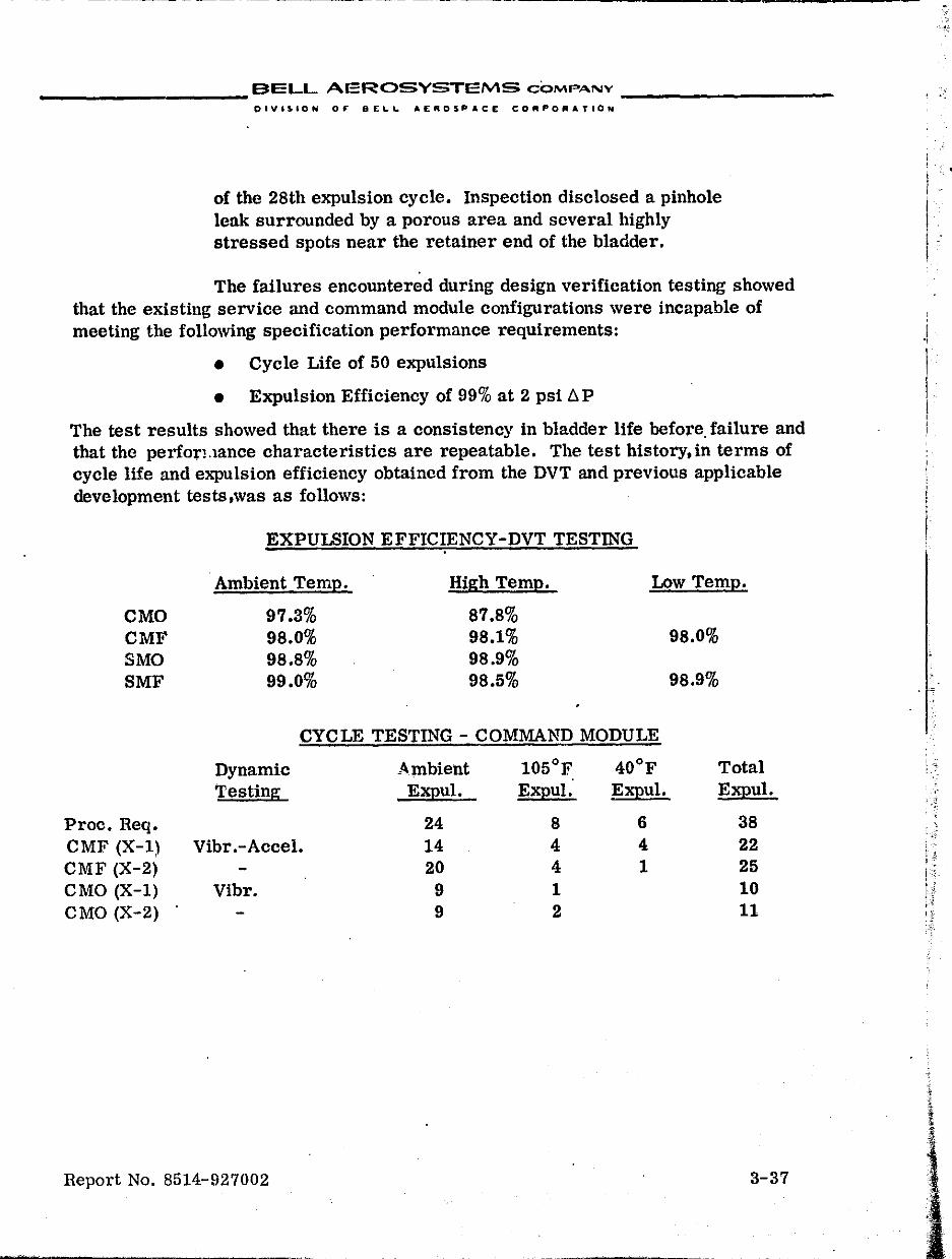
~-----------------------------------------,-------
__________ SELL AEROSYSTEMS COMPANY _________ _
DIVISION OF DELL AEROSPACE COIIIPOR.TIO,.
of the 28th expulsion cycle. Inspection disclosed a pinhole leak surrounded by a porous area and several highly stressed spots near the retainer end of the bladder.
The failures encountered during design verification testing showed that the existing service and command module configurations were incapable of meeting the following speCification performance requirements:
• Cycle Life of 50 expulsions
• Expulsion Efficiency of 99% at 2 psi /J. P
The test results showed that there is a consistency in bladder life before, failure and that the perforLlance characteristics are repeatable. The test history, in terms of cycle life and expulSion efficiency obtained from the DVT and previous applicable development tests,was as follows:
EXPULSION EFFICIENCY-DVT TESTING
Ambient Tern!:!. High Tern!:!. Low Temp.
CMO 97.3% 87.8% CMF 98.0% 98.1% 98.0% SMO 98.8% 98.9% SMF 99.0% 98.5% 98.9%
CYCLE TESTING - COMMAND MODULE
Dynamic Ambient 105°F 40°F Total Testing E~ul. Expul. E~ul. E~u1.
Proc. Req. 24 8 6 38 CMF (X-I) Vibr.-Accel. 14 4 4 22 CMF (X-2) 20 4 1 25 CMO (X-I) Vibr. 9 1 10 CMO (X-2) 9 2 11
Report No. 8514-927002 3-37
, ,
I
I "
I I I , !
, -,
,
: :
, j '0 ' ;~
, 1 . ;.~ ; .
r f i' II ; '5 I) .:::
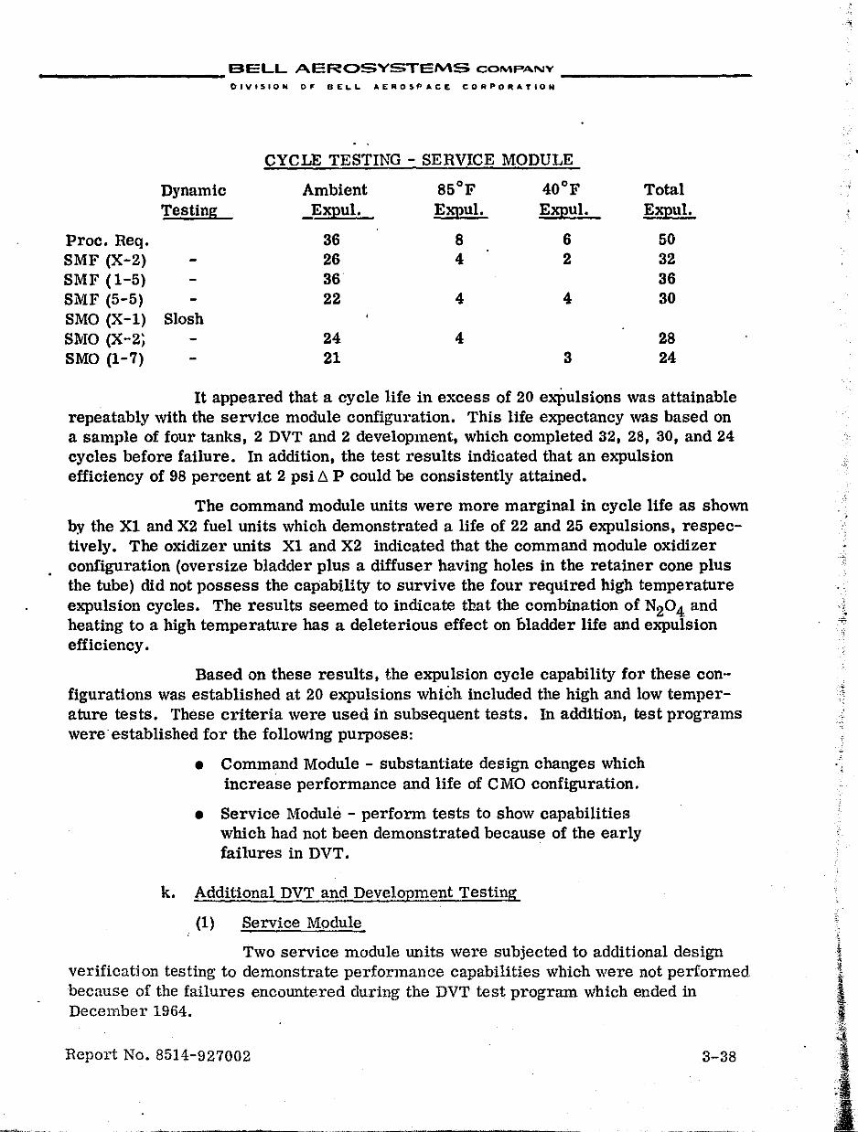
__________ BELL AEROSYSTEMS COMPANY _________ _
DIVIS'ON 0'- OEL.L AERO$PACE CORPORATION
• I
CYCLE TESTING - SERVICE MODULE
Dynamic Ambient 85°F 40°F Total Testing Expul. E2illul• E2illul. E2illul.
Proc. Req. 36 8 6 50 SMF (X-2) 26 4 2 32 SMF (1-5) 36 36 SMF (5-5) 22 4 4 30 SMO (X-1) Slosh SMO (X-2~ 24 4 28 SMO (1-7) 21 3 24
It appeared that a cycle life in excess of 20 exPulsions was attainable repeatably with the servIce module configuration. This life expectancy was based on a sample of four tanks, 2 DVT and 2 development, which completed 32, 28, 30, and 24 cycles before failure. In addition, the test results indicated that an expulsion efficiency of 98 percent at 2 psi /:::,. P could be consistently attained.
The command module units were more marginal in cycle life as shown by the Xl and X2 fuel units which demonstrated a life of 22 and 25 expulsions, respectively. The oxidizer units Xl and X2 indicated that the command module oxidizer configuration (oversize bladder plus a diffuser having holes in the retainer cone plus the tube) did not possess the capability to survive the four required high temperature expulsion cycles. The results seemed to indicate that the combination of N20 4 and heating to a high temperatv,re has a deleterious effect on bladder life and expulsion efficiency.
Based on these results, the expulsion cycle capability for these configurations was established at 20 expulSions which included the high and low temperature tests. These criteria were used in subsequent tests. In addition, test programs were established for the following purposes:
• Command Module - substantiate design changes which increase performance and life of CMO configuration.
• SerVice Module - perform tests to show capabilities which had not been demonstrated because of the early failures in DVT.
k. Additional DVT and Development Testing
(1) Service Module
Two service module units were subjected to additional design verification testing to demonstrate performance capabilities which were not performed because of the failures encountered during the DVT test program which ended in December 1964.
Report No. 8514-927002 3-38
l
1 1 I:,.
.. .
___________ B.ELL AEROSYSlEMS CQMP"NY _________ _
DIVIS.ON OF DELL AEAOSPjO,CE CORPORATION
SMF Unit X-2: The unit completed a total of 19 expulsion cycles (12 ambient, 4 high temperature and 3 low temperature) before bladder failure. However, bladder helium leakage rates exceeded the specified 210 c~/15 minutes following the fourth high temperature test (expulSion No. 16).
SMO Unit X-I: The tank assembly was subjected to Y-axis, flange-down, vibration. After 11 minutes and 15 seconds of the run, one of the flange mounting bolts and the helium port fitting were broken. The tank was then drained and the helium port fitting and bolt were replaced. Subsequently, both a tank assembly and bladder leak check were performed with acceptable leakage rates. The tank was then reinstalled in the fixture and the remaining 3 minutes and 45 seconds of Y-axis random vibration were completed. The tank was then drained and reinstalled in preparation for Z-axis vibration. Upon filling, liquid appeared on the gas side of the tank indicating the bladder had failed.
A development unit was tested to demonstrate the capability of performing the propellant exposure and revised slosh test. The results are as follows:
SMO Unit Y-2: This unit successfully completed slosh testing at 37°F with the tank in the vertical position and slosh inputs in the lateral axis. The specification requirements had been changed to require that the test be conducted with the major axis in the vertical position and the reciprocating motion applied perpendicular to the longitudinal axis. The slosh failure during DVT (SMO Unit X-I) had occurred with"the tank horizontal and inputs parallel to the 10Dgitudinai axis.
The unit was subjected to propellant exposure testing with N204 at a temperature of +105 of. Tank shell failure was indicated after 23 days of exposure. The failure was located in the parent metal of the cylindrical section,approximately 1-inch from the weld, and consisted of four crack areas. All the cracks did not penetrate through the shell thickness,and salt deposits were found on the internal surface of the shell in the vicinity of the failure. This unit had been exposed to propellant for a total of 49 days because oLprevious testing.
(2) Command Module Oxidizer Tank Development
A test program was initiated on the R-series tanks to provide data to evaluate changes tailored to increase the performance of the CMO tanks.
Report No. 8514-927002 3-39
r I
..
;
I : j,
I', , 11
-5 i j
If I ~ 1 fitI
f i
.. -.~"" .•. -... _~ '···.911,,,,0nV
__________ BELL AEROSYSTEMS CO'lo\p·",,,y ___ _
OIVISION or &£'-1.. AEROSPACE CORPO;Z:""'OH
The occurrence of both DVT CMO tUlit failurt'H ,1111'1111: hll,1I temperature testing indicated that N204 heated to the high tempC\':III1I'" within lile propellant tank had a deleterious effect on bladder life. Low explllsl',1I ,.III..It'"ey always accompanied the high temperature tests. Since tl:is phenll 11lt'lll)il fll'l'lIl'rI \~hen
gas pockets are located inside the blad~er, it wal:> conjec:ured thai inl"" ""P'It"I/'Il'-injt gas plus N204 vapors accumulated durmg the heating cycle and (';lllHI'd lill' hlndder and e,.qJUlsion efficiency degradation.* Therefore, two ce\'elopnwnl 1I1111!1 (Ii I and R-2) were subjected to testing with the following major test modifkatl'lII:
• The N204 was thoroughly degassed before loading flllli the pressurizing gas on the load tank was chall~t~d 11'1,,,, nitrogen to helium.
• After the expulsion at high temperature, the Pl'l)lltdlll',,1 assembly was cooled to ambient temperature nfte,' 111('
bladder was expanded to the tank wall to pre"t"llt HI!VI' \'1'
high temperature, high pressure foles.
CMO Unit R-1: The tank assembly (standard diffuser' flllll
oversize bladder) was subjected to expulsion testing with N204' Twelve expulsions (9 ambient and 3 hot) \\,\.'re (!Oll\ '
pleted for a total of17 bladder cycles. Bladder failure occurred upon completion of expulsion ~o. 12.
CMO Unit R-2: This unit (standard diffuser and ll£'t-Rlw bladder) completed 20 expulsion cycles 'c,ith N20., (9 :11111,11'111., 4 hot, 4 cold, 1 ambient, and 2 ambient pulsed), No bllldlll'l' damage was incurred; however, the expulsion efficlclley \V1I1l
quite low (approximately 90%) and an appreciabk dcc "(lIllIt' in expulsion efficiency was noted at the l::igher t£'1\\\1u ":I 1.111'1'. The tank was then subjected to flow che cks with Freon 'I' "', both at rated tank pressure and at 20 pSig, to det£'l'milw IIIl' effect of pressure variation and the expu.lsion mediulll 111'1\1\
the expulsion characteri.stics, The pressure vari:lhlu IU'I'"lI'd
to have no measureable effect upon expulsion effil'it'lltly: hllW'.
ever the Freon-TF appeared to give efficiencies IlOI1)(lWhl'I'(' between N204 at ambient and high temperature,
'" CIl,10 Unit R-4: Expulsion tests with water in the plexiglass tank Wlll'll lIIlIII" to observe the effect of gas in the propellant upon bladder folding anti lixjJlIl:-llllll characteristics, Two ambient expulSions were made as follo\\'s: Onu wllh I.he tank loaded normally with no gas in bladder, and one with ti::e tank lO:ldeci 1111 1'11I!llJy and then apprOXimately 100 cu !n. of water displaced by g;5 in the hlnd"!"" '\'ht'/lc tests were repeated at 105 F.
Report No. 851<1-927002 :)··10
•
__________ BELL AEROSYSTEMS COMPANY _________ _
DIVISION OF' DELL AEROSPACE CQRPORATION
Because of the unsatisfactory high temperature life cycle performance of the CMO configuration, a redesign was initiated. Since the B-2 unit with a net size bladder had demonstrated acceptable life cycle characteristics but poor expulsion efficiency, the decision was made to change the configuration to inc.:lude holes in the flange cone as well as the retainer cone of the diffuser plus using a net-size bladder. Simultaneously with this change, the liquid side vent pro.visions were incorporated into the design. A development modelUquid side vent configuration assembly (B-3) was built which incorporated a 3/16-inch liquid side vent tube within a 5/S-inch diameter diffuser tube (.049 inch wall). A Teflon spacer was inserted between the liquid side vent tube and the diffuser tube. There were 216,.032-inch holes in the retainer cone and 150 in the flange cone. This unit was tested as follows: ...
CMO Unit B-3: This unit fnet-size bladder) completed a total of seven ambient expulsions with N204 prior to bladder failure. Several excessive residuals were obtained and expulsion efficiency varied from approximately 93 to 99% at a L:u> of 2 psi. The bladder failure occurred at the retainer hemispherical portion of the bladder. The U-shape appearance of the failure. plus the location of other highly stress areas in the same vicinity, indicated that severe folding and creasing must have occurred.
Since the most obVious hydraulic difference between R-2 and B-3 units was the reduced flow area of the B-3 caused by the insertion of the bleed tube plus the Teflon support spacer it was believed that this premature failure was related to an unbalanced pressure distribution along the diffuser tube. The folding patterns of B-2 and B-3 were observed with net"':size bladders in a plexiglass tank during horizontal expulsion to determine whether any noticeable difference eould be detected. Colored Freon-TF was used to simulate the density of N204. No noticeable differenc.e in the folding patterns could be discerned. The B-3 unit was then modified to an B-7 configuration which consisted of replacing the .094 inch wall diffuser tube with a .028 inch wall and removing the Teflon spacer. This made the tube crosssectional flow area practically equivalent to that of B-2. This unit was assembled with a full size bladder,and a total of 23 expulsions with Freon-TF were completed to study diffuser hole patterns which were varied by taping the diffuser. Expulsion efficiencies of approximately 97% were obtained; however, the fold sequenee and severity of the creases looked similar to that observed with B-2 and B-3.
The severity of the folds at the retainer raised the possibility of bladder degradation. Since earlier twist investigations showed that an improvement was produced if all the diffuser tube holes were closed, a test was performed on the
Beport No. 8514-927002 3-41
..
"
__________ BELL AEROSYSTEMS COMPANY _________ _
B-7 net-size bladder configuration flowing only through the cones with the diffuser tube holes masked. This was tested in a plexiglass tank with freon and the terminal fold pattern was improved relative to the basic B-7 teat. The severe creases and folds ncar the retainer were not in evidence; however, the expulsion' efficiency decreased to a range of 93 to 98%.
The objective was to obtain more repeatable and higher expulsion efficie'1.~Y while maintaining the fold pattern.
The local flow rate is controlled primarily by the pressure drop within the bladder filled channels which lead to openings in the diffuser, in addition to the drop through the diffuser holes left uncovered by the bladder. Two tests were performed in a plexiglasF.: t'lnk to further localize the effects of bladder resistance versus diffuser hole resistal:ce. The results are as follows:
• A Teflon catenary tube was installed between the cones of the basic B-7 diffuser to eliminate the effect of varying flow resistance caused by bladder folding. The expulSion efficiency with this modification was repeatable and high ( > 98%).
• A concentric cone made of perforated metal was constructed around the retainer cone of the B-2 unit, to assess the effect of retainer cone open area. The test results indicated an improvement in eJijlulsion efficiency of approximately. 3% over that .obtained on Unit B-2.
The test results indicated that both the bladder and the diffuser tube resistances determined the expulSion efficiency an.d the fold pattern; howe,rer, the bladder resistance was dominant in producing the terminal high pressure rise.
CMO Unit B-7A: After the plexiglass tank efficiency testing, Unit B-7A was assembled with a metal shell and a liquid side vent diffuser with enlarged (.040 inch) holes in the retainer and flange cones. A total of 18 expulsion cycles with N204 were completed on this unit prior to bladder failure. These included 14 ambient (2 of which were at low flow condition) and 4 high temperature cycles. The tank was refurbished with a new bladder, SN 34-.3, and subjected to testing to determine the expulsion characteristics during acceleration. Four 2g constant
. acceleration expulSion tests were performed without structural damage. ExpulSion effiCiencies, based on a minimum differential pressure of 3 psi, varied from 90.7 to 92.7%.
Report No. 8514-927002 3-42
__________ BELL AEROSVSTEMS COMPANY _______ • __ _
OIVI'ION 0" .I:",L AEROSPACE CO""O"AVION
A command module fuel tank assembly (R-S) was assembled ,·-:·h the same configuration as CMO Unit R-7A(l1et-size bladder and liquid side vent diffuser with .040 inch holes in the cones.
eMF Unit R-8: Twenty expulsion cycles were performed with MMH in accordance with the established DVT Procedure (12 ambient inclucling 2 puised, 4 hot, and 4 cold). Expulsion No. 21 was the fuel jettison test in which the tank was emptied in approximately 7 seconds. Bladder failul'e was encountered at the end of the jettison test. The unit demonstrated more than 9S% expulsion efficiency at 2 psi 6. P at specified flow rates and temperatures. This R-S configuration was selected as the DVT configuration.
CMF Unit R-8A: Unit R-8 was redesignated R-SA after refurbishment with a new bladder subsequent to the fuel jettison test. The refurbished unit was subjected to an accelerationexpulsion (20g to 2g) test and demonstrated an expUlsion efficiency of 98.5% at 2g with a 6.P of 2 pSi. The tank was then subjected to DVT level vibration inputs and successfully passed sine and random vibration in the X-axis. However, during pretest service for Y-axis vibration, bladder failure was encountered.
The command module oxidizer unit presented a major problem because of the limited life cycle capability and low expulsion efficiency experienced during high (105°F) temperature heating and expulsion. Testing on the R-series tanks showed that the bladder folding pattern had to be controlled so that the ends did not collapse and prevent propellant flow through the flange and retainer cones. Two approaches were taken to prevent the bladder ends from collapsing prematurely:
1. Internal mechanical restraint
2. Inherent bladder structural restraint
CMO - Mechanical Restrainers: Two expulSions were made with Freon-TF in the plexiglass tank using a net-size bladder, SN 16-3. Three 1/4-inch flexible Teflon tubes were installed longitudinally, 120 0 apart, along the diffuser tube. Each tube formed a loop with the center of the 10llp approximately three inches from the diffuser tube. An expulsion efficiency approximately 4 percent greater than that obtained without the restrainers was experienced in both tests.
Report No. 8514-927002 3-43
-*-' '~" ----~~~~--~~------
j"' , ..
,
I· . ~
I'.'· II , .
__________ BELL AEROSYSTEMS COMPANY _________ _
DIVISION 0,: DEL.L. At:R05P.C~ C::ORPORATION
CMO - Heavy Wall Bladder - Six expulsions were made with Freon-TF in the plexiglass tank using a net-size bladder having a 6 mil cross section in the cylindrical section a.ld 9 mil cross section in the hemispherical ends. The expulsion efficiency was approximately 4 percent greater than that obtained with the standard 6 mil bladder.
Based on the successful results of the plexiglass tank testing, a development unit (R-9) was assembled with the liqUid side vent diffuser (same as R-8A) and thic~{enedend bladder {or testing to the DVT sequence.
CMO Unii: R-9; A total of 21 expulsion cycles were completed in the following sequence; 11 ambient, 2 high temperature, 4 low temperature, and 2 high temperature with N20 4 plus one acceleration expulsion at 2g and one at Ig \'1ith Simulated propellant. The tank was then subjected to DVT level vibration inputs in all three axes. Upon completion of the final axis (Z-axis) bladder frilure was noted. The expUlsion efficiency at low and ambient temperature was greater than 98%, while at 105°F the afficiency was about 94%. The efficiency decreased to about 96% during 2g acceleration.
Based on the results of testing on this unit, the R-9 design was selected as the configuration for formal testing.
Report No. 8514-927002 3-44
-r&
.l{ :~~
.,~~-
__________ BELL AEROSYSTEMS COMPANY
DIVISION OF DIELI,. .£~OSP"CE CONPORATI()N
4. Qualification Configuration Formal Testing
Al1 development effort was stopped in March 1965 and preparation was made to start formal testing on al1 four tank configurations. These were as follows:
Configuration
Service Module Fuel Service Module Oxidizer Command Module Fuel Command Module Oxidizer
Bell Part No.
8271-471151-1 8271-471152-1 8271-471153-1 8271-471154-1
The sequence of events and tests are shown in Figure 111-5.
Two tank assemblies of each configuration were to be subjected to the qu::.lification and off-limit test sequence specified in the following North American Aviation specifications, as modified by the specification control drawing (SCD):
Configuration
Service MQdule Fuel Service Module Oxidizer Command Module Fuel Command Module Oxidizer
NAA SpeCification
MC 282-0008 MC 282-0004 MC 282-0007 MC 282-0006
NAA SCD
ME 282-0008 ME 282-0004 ME 282-0007 ME 282-0006
The final sequence of tests for each unit is shown in Table II-2. The dynamic test levels are shown in Table 11-3.
Qualification testing was conducted to demonstrate tank conformance to the specification requirements. Off-limit testing was then performed on the same test units to accrue additional test data for reliability assessment, and to verify critical environmental and functional design margins by testing to failure. Other formal testing included design substantiation testing to provide supplemental data on the command module tank performance, and propellant exposure testing onthe service module configurations. The propellant storage program was a separate program which resulted from the titanium/N204 stress corrosion problem.
a. Service Module Tank Assembly Testing
The service module tests were performed with the tank assembly in the vertka! position. ExpulSion testing was performed with the tank assembly oriented flange-up for half of the tests ::md flange-down for the rem&inder. Dynamic testing was planned so that both attitudes would be tested in each axis insofar as was
Report No. 8514-927002 3-45
,
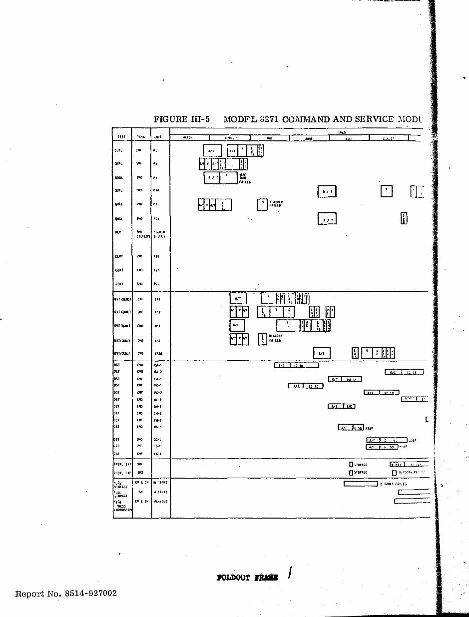
FIGURE III-5
lUI ",,,
QUAL '"' " gUiL , ..
" QUAL .. , " QUll '" ... QUIL ,..,
"
'"' IIlV SMa ~'IUQIII
I1HlQU SHLlll
,.,
cnl '''' C[III , ...
QVf{PI,,) C6IO
QVJ(~) CIIIII
'" '" DS1
0" OS!
DS1
'" OS!
" "
'" '''' '" '" "" "" '''' '''' '" ''''
PROP. lJP SII(I
'I'
'"
...
."
'"
0.-1
OA-l
fA-I
Fe-1
fC-2
CC-1
"'-, OH-2
nH
OIHI
OG·L
fl;.!1
fG-l
~104 COl & ~'* 10 II;H(3 STORAGE
1\ 14Hes
ijlll, ,If ,SII \"ijIOUS IAHS
IORAO~'OH
Report No. 8514-927002
.
------~- ---~---- .. ----
MODFL 8271 COJ\HvIAr-.ro AND SERVICE :'IODl
...
r-;-t.UDDiII U fAIUD
".(
o I' 1*1 !, Iliutl
I J\i\.l
EIfl I i, I ' I q [ill] EEl EJ I' W I I. I!I~ EffI OJ ''.J~DEII ) fAIL[D
:'f; ,.
[J
ID
ru I • I t IW 1:1 I 1'1 I tA sa :::::::J
I 'tl I 'j a I I AlT I It U I
I ,II I lC lQ I IW1ull i
(! I: :::-:::II:::I':·
I
[!II 'm'
1,,, I, 5" I_:tp lilT I" \0 I"l.~
OsrOPPlr.
OSrOl'PUi
Ie F" I '"" ." o t,l;·.~. ~J"~;
(
•
\ ,.
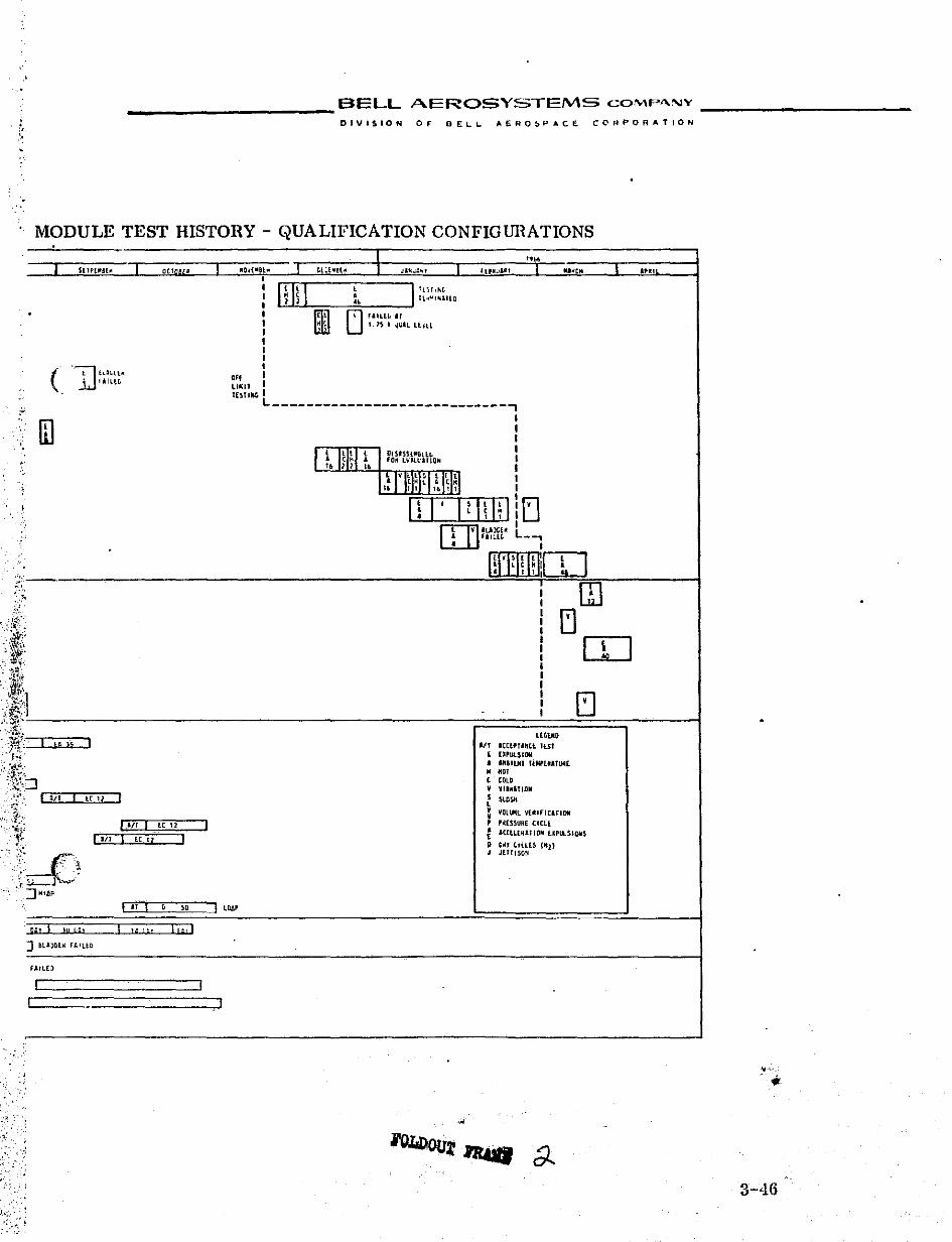
___________ BELL AEROSYSTEMS COMP"'lY
DIVISION OF DELL AERO~P"CE CORPORATION .. ,
MODULE TEST HISTORY - QUALIFICATION CONFIGURATIONS
_I Sl "lIt!(~ I
.
( +'"TI h~\.ll~ IIIH~
• ill . l ,
.,
:;
I I I - if 1'i
-. ::J
I '" I lC 11 I
I_lIT I
:. ."';-; '--,t ',,-( >' - ..
u-{"""; .
' .. '. ",-.
. '
::J 11161'
p;t I !p ['"I
] tlUJtol~ r'IUD
~Arl()
I I
I itT I lC 11
I " I I H 1-'
OCJl1U!' I
LC 12 I I
, " I
It;'!
I I
I " .. _Oll_H" tl:l"el~ J'J;~'~, I Il' .... ~1 I IU~'" L a,.,
I I I ! III l III 'iT ,hG I • I "
ll""I"~llll
I
Illll o FIILlL I'
I ~ l 1. IS • ~U'L Llnl I I I I I
'" I
LlII:IT I lUtiNG I L ____________________________ ,
I I I
'tIHH~, DIS'SSUllillt. I ,O~ bllll'\IIOH I
I
.: rlH~FL~I\m I I
I I I
l . Iq\I~I:rJ • • [IJ]ILllW L • f&1~lL __ ,
• I
\!I'FHI!I[O I m I I IJ I I I C[J I I I I I I [:J I I
LUiUtD III ICtl'UHtl IlSI , UI'Ul$IOM
• ,"aiUlI IUlP'ua'lJji(
• '" , COLD V VI""lliDIt
• l SUISit
V YOl~t V(IIIFltITlOlli , , '~nSURE C1Cll • £(ClLElll11011 llPll.SIONS E
• ~~r (.f~L(S (H2) , JETtiSON
L[lAP
__________ BELL AEROSYSTEMS COMPAN'- _________ _
DIVISION 0,- BELL "'£R05~ACE CO"PORATION
practicable; however, off-limit testing was performed in the attitude deemed most detrimental to the unit. Vibration testing was performed using simulated propellant,and water was used for shell pressure cycle testing. All other testing was accomplished with actual propellant - N20 4 oxidizer and 50/50 blend fuel.
Expulsion cycling was parformed at nominal operating pressure (179 psig) to demonstrate conformance to the folloWing requirements:
Cycle Life - 20 expulsions consisting of 16 at ambient temperature (65 to 75°F), 2 at low temperature (35 to 40°F), and 2 at high temperature (85 to 90°F).
Expulsion Efficiency - Demonstrate efficiency of 98% at a b.P of 2 psi at high flow rate and 99% at a b.P of 2 psi at low flow rate. The extra low flow demonstration was performed only if the 99% requirement was not attained at the high flow rate.
(1) Service Module Fuel Qualification
Qualification testing of two SMF tank assemblies was performed in accordance with the procedures contained in Bell Report 8271-928007, Revision A. Unit P-1 successfully completed the test series consisting of vibration in two axes, 16 ambient expulSions, 2 high temperature expulsions, and 2 low temperature expulSions. Unit P-2 successfully completed the test series consil1ting of shell pressure cycling, 16 ambient expulSions, vibration in two axes, 2 high temperature expulSions, and 2 low temperature expulsions.
(a) Vibration
Each unit was subjected to vibration testing in two axes. The P-1 unit vibration was conducted in the flange-down position for the X-axis and flange-up position for the Y-axis. Unit P-2 vibration was conducted in the flangedown position for the X-axis and the Z-axis. Unit P-1 was subjected to a 2 g sinusoidal survey and random vibration while the P-2 unit was subjected to random Vibration only. This testing was completed without incident.
. (b) Expulsion Cycling
The tank assemblies were subjected to propellant expulSion tests with all expulsion reqUirements accomplished successfully. The mean expulSion efficiency for both :anks was in excess of 99% for bothattttudes at all temperature conditions,and no significant difference in expulSion efficiency or characteristics due to temperature or attitude was noted.
Report No. 8514-927002 3-47
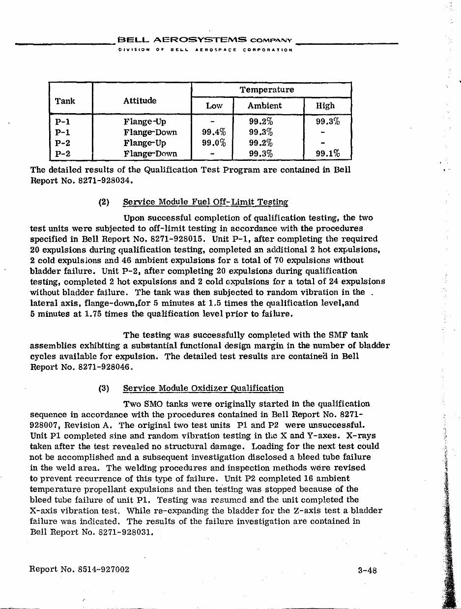
__________ BELL AEROSYSTEMS COMPANY _________ _
DlylSION OF DEL.L. AEROSPACE CORPORATION
Temperature Tank Attitude Low Ambient High
P-l Flange-Up - 99.2% 99.3% P-l Flange-Down 99.4% 99.3% -P-2 Flange-Up 99.0% 99.2% -P-2 Flange-Down - 99.3% 99.1%
The detailed results of the Qualification Test Program are contained in Bell Report No. 8271-928034.
(2) Service Module Fuel Off- Limit Testing
Upon successful completion of qualification testing, the two test units were subjected to off-limit testing in accordance with the procedures specified in Bell Report No. 8271-928015. Unit P-1, after completing the required 20 expulsions during qualification testing, completed an additional 2 hot expulSions, 2 cold expulsions and 46 ambient expulsions for a total of 70 expulsions without bladder failure. Unit P-2, after completing 20 expulsions during qualification testing, completed 2 hot expulsions and 2 cold oxpulsions for a total of 24 expulsions without bladder failure. The tank was then subjected to random vibration in the lateral axis, flange-down,for 5 minutes at 1.5 times the qualification level,and 5 minutes at 1.75 times the qualification level prior to failure.
The testing was successfully completed with the SMF tank assemblies exhibiting a substantial functional design margin in the number of bladder cycles available for expulsion. The detailed test results are containea in Bell Report No. 8271-928046.
(3) Service Module Oxidizer Qualification
Two SMO tanks were originally started in the qualification sequence in accordance with the procedures contained in Bell Report No. 8271-928007, Revision A. The original two test units P1 and P2 were unsuccessful. Unit P1 completed sine and random vibration testing in the X and Y-axes. X-rays taken after the test revealed no structural damage. Loading for the next test could not be accomplished and a subsequent investigation disclosed a bleed tube failure in the weld area. The welding procedures and inspection methods were revised to prevent recurrence of this type of failure. Unit P2 completed 16 ambient temperature propellant expulsions and then te"sting was stopped because of the bleed tuhe failure of unit PI. Testing was resmncd and the unit completed the X-axis vibration test. While re-expanding the bladder for the Z-axis test a bladder failure was indicated. The results of the failure investigation are contained in Bell Report No. 8271-928031.
Report No. 8514-927002 3-48
. -
__________ BELL AEROSYSTEMS CQMP""NY __________ _
DIVISION OF PEI,..L.. AEROSPACE CORPORATION
The two test units were refurbished into units PIA and P2A, and the qualification test sequence was started in accordance with Revision B of the procedure. These refurbished units also failed to meet the life cycle requirements. Unit PIA successfully completed vibration in the X and Y-axes, slosh testing, and eleven ambient temperature expulsions prior to bladder failure. The results of the failure investigation are contained in Bell Report No. 8271-928048. Unit P2A completed eight ambient temperature expulsions before bladder failure. The details of the failure are contained in Bell Report No. 8271-928047.
(4) Service Module Oxidizer Development
. Testing was stopped at this point and the units were not refurbished pending a solution to the SMO configuration problem. The SMF tank assemblies had successfully completed qualification testing and the only difference between the fuel and oxidizer tanks was propellant used and tank length. The additional length of the SMO tank over the successful S1\IF configuration made it marginal, regarding normal repositioning of the bladder upon re-expansion after an expulsion,because of greater friction between the bladder and tank wall. A development effort was initiated which consisted of the following efforts:
• Teflon coating the inside of the shell to reduce the friction coefficient,thus permitting the bladder to slide on the tank wall and reduce biaxial stresses necessary to lift the bladder
• Mechanical smoothing of the inside of the shell to reduce friction
• Bladder redesign with underSized center section to eliminate wall friction during bladder expansion
Tests showed that mechanical polishing for reduced friction was marginal and impractical; however, experiments indicated that a Teflon lined shell offered a solution to the repositioning problem. At this time Teflon coated shells were being fabricated for use on the titanium/N20 4 stress corrosion progr;.m to determine if the Teflon lining would serve as a barrier to retard the stress
. corrosion. One of these shells SMO,SNOOI0 was assembled for propellant expulsion testing. The unit successfully completed 16 ambient temperature, 2 cold, 2 hot, and 16 additional ambient temperature expulSions without failure. The uni.t was disassembled for evaluation and the decision was made to reassemble the tank with a new bladder and subject it to the qualification test series. Based on the success of this unit, all other design and development activity was stopped.
Report No. 8514-927002 3-49
" ,":.
__________ BELL AEROSYSTEMS COMPANY _________ _
DIVISoION OF pELL AEROSPACE CORPORATION
The refurbished test unit was subjected to the qualification test sequence plus additional expulsion testing. The unit successfully completed 16 ambient temperature expulsions prior to qualification vibration. DUling vibration the old configuration bleed tube, which had been used because of the unavailability of production configuration diffusers, failed; however, testing was continued by using the command module style vacuum loading technique. Vibration was completed and the unit then !'uccessfully completed one cold and one hot expulsion, slosh, 16 ambient temperature expulsions, one cold and one hot expulsion without bladder failure. All expulsion efficiencies were above 99%.
Although the first series of tests on the Teflon coated shell indicated that it would meet the qualification test reqUirements, an analysis of the schedule indicated that refurbishment of flight line tanks could not be accomplished in time for use. The existing test data from units PI, P2, PIA, and P2A provided a basis for a reduction in the required number of expulsion cycles. As a result, a certification program, designed to demonstrate the capability of the SMO configuration of performing to the lowered requirements, was initiated shortly after the beginning of the second test series on the Teflon-lined shell.
(5) Service Module Oxidizer Certification Testing
Certification testing was accomplished on two SMO tank asaemblies to der.:lonstrate that they were capable of performing to the modified qualification test requirements of the North American Aviation specifications. The testing was performed in accordance with the proced~res contained in Bell Report Nt,;. 8271-928045. Unit PlB successfully completed the test series consisting of four ambient propellant expulsions, vibration in two axes, slosh test, one low temperature propellant expulsion, and one high temperature expulsion. Unit P2B failed during vibration test after completing the four ambient propellant expulsions. The unit was refurbished as unit P2C and successfully completed the test series conSisting of four ambient propellant expulsions, vibration in two axes, slosh test, one low temperature propellant expulSion, and one high temperature propellant expulsion.
(a) Vibration
Units PlB and P2C were subjected to random vibration testing in the Y-axis lateral,flange-up and the X-axis longitudinal,flange-down position. During-the X-axis test on unit P2C, the Teflon bushing at the boss end became dislodged. The test was stopped, the bushing was reinstalled, and the test was completed.
Report No. 8514-927002 3-50
• r '::'
__________ BELL AEROSYSTEMS COMPA.NY _________ _
DIVISION OF DEI.1.. AEROSPACE eORPORATIOt4
(b) Slosh
Slosh testing was successfully perfonned on both the PIB and the P2C units. The units were installed in the flange-up attitude, loaded to 50% capacity with nitrogen tetroxide, .and subjected to 500 slosh cycles at ambient tem perature.
(c) Expulsion Cycling
Each of the units PIB and P2C were subjected to propellant expulsion cycling to demonstrate the following:
Cycle Life - Perform six expulsions consisting of four ambient temperature expulsions,flange-down, one low temperature expulsion,flange-up, and one high temperature expulsion,flange-up. An additional three expulsions were accomplished during emptying after the X-axis Vibration, Y-axis vibration, and the slosh test.
Loadability - To demonstrate the ability to load the units to the acceptance test volume-weight equivalent ±1.0 pound.
Expulsion Efficiency - To demonstrate an expulsion efficiency of at least 98% at 2 psi differen~ial pressure.
Each of the test units completed the four expulSions at ambient temperature with expulsion efficiencies at 2 psi llP ranging from 99.5 to 99.6 for the PIB unit and from 99.1 to 99.7 for the P2C unit. Each unit then successfully completed one low temperature and one high temperature expulsion in the flange-up altitude. The expUlsion efficiencies for the low temperature expulsions for PIB and P2C were 99.5 and 99.4, respectively. The expulsion efficiencies for the high temperature exrJulsion for the PIB and P2C units were 99.6 and 99.8, respectively. The detailed test results are contained in Bell Report No. 8271-928049.
(6) Service Module Oxidizer Off-Limit Testing
After completion of certification testing, SMO units PIB and P2C were subjected to off-limit testing in accordance with the procedures specified in Bell Report No. 8271-928015. Unit PIB, which had completed certification testing, was then subjected to random vibration in the lateral Y-axiS, flange-down atti tude, for 5 minutes at 1.0 times certification level and 5 minutes at 1.5 times certification level. Unit P2C, after completing ceJ."tification testing, was subjected to 48 additional ambient temperature propellant eJ..-pulsions without bladder failure.
Report No. 8514-927002 3-51
I
I
I .
, .
, 'i
; . t
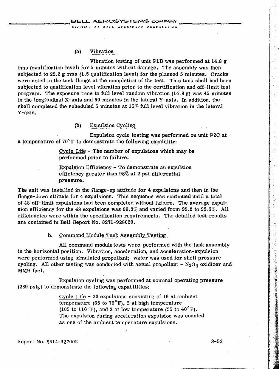
__________ BELL AEROSYSTEMS COMPANY __________ _
DIVISION OF DELL AEROSPACE CORPORATION
(a) Vibration
Vibration testing of unit P1B was performed at 14.8 g rms (qualification level) for 5 minutes without damage. The assembly was then subjected to 22.2 g rms (1.5 qualification level) for the planned 5 minutes. Cracks were noted in the tank flange at the completion of the test. This tank shell had been subjected to qualification level vibration prior to the certification and off-limit test program. The exposure time to full level random vibration (14.8 g) was 45 minutes in the longitudinal X-axis and 50 minutes in the lateral Y -a..xis. In addition, the shell completed the scheduled 5 minutes at 15% full level vibration in the lateral Y-axis.
(b) Expulsion Cycling
Expulsion cycle testing was performed on unit P2C at a temperature of 70°F to demonstrate the following capability:
Cycle Life - The number of expulSions which may be performed prior to failure.
Expulsion Efficiency - To demonstrate an expulsion efficiency greater than 98% at 2 psi differential p:ressure.
The unit was installed in the flange-up attitude for 4 expulsions and then in the flange-down attitude for 4 expulsions. This sequence was continued until a total of 48 off-limit expulsions had been completed without failure. The average expulsion efficiency for the 48 expulSions was 99.3% and varied from 99.2 to 99.5%. All efficiencies were within the specification requirements. The detailed test results are contained in Bell Report No. 8271-928050.
b. Command Module Tank Assembly Testing
All command module tests were performed with the tank assembly in the horizontal position. Vibration, acceleration, a..'1d acceleration-expulsion were performed using simulated propellant; water was used for shell pressure cycling. All other testing was conducted with actual proiJcllant - N204 oxidizer and MMH fuel.
Expulsion oycling was performed at nominal operating pressure (289 psig) to demonstrate the follOWing capabilities:
Cycle Life - 20 expulSions consisting of 16 at ambient temperature (65 to 75 OF), 2 at high temperature
. (105 to HO°F), and 2 at low temperature (35 to 40°F). The expulsion during acceleration expulsion was counted as one of the ambient temperature expulsions.
Report No. 8514-927002 3-52
•
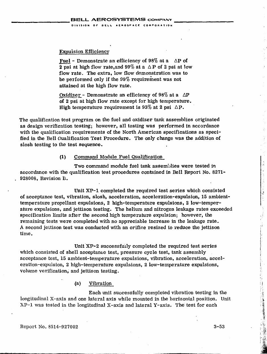
__________ BELL AEROSYSTEMS COMP,''''y _________ _
DIVes,ON OF DELL AERO~PIt.CE CORPORATION
Expulsion Efficiency
Fuel - Demonstrate an efficiency of 98% at a .6P of 2 psi at high flow rate,and 99% at a .6 P of 2 psi at low flow rate. The extra, low flow demonstration was to be performed only if the 99% requirement was not attained at the high flow rate.
Oxidizer - Demonstrate an efficiency of 98% at a 6P of 2 psi at high flow rate except for high temperature. High temperature requirement is 93% at 2 psi .6P.
The qualification test program on the fuel and oxidizer tank assemblies originated as design verification testing; however, all testing was performed in accordance with the qualification requirements of the North American specifications as specified in the Bell Qualification Test Procedure. The only change was the addition of slosh testing to the test sequence.
(1) Command Module Fuel Qualification
Two command module fuel tank assemblies were tested in accordance with the qualification test procedures contained in Bell Report No. 8271-928008, Revision D.
Unit XP-l completed the required test series which consisted of acceptance test, vibration, slosh, acceleration, accelerlltion-expulsion, 15 ambienttemperature propellant expulsions, 2 high-temperature expulsions, 2 low-temperature expulsions, and jettison testing. The helium and nitrogen leakage rates exceeded specification limits after the second high temperature expulsion; however, the remaining tests were completed with no appreciable increase in the leakage rate. A second jcttison test was conducted with an orifice resized to ;:educe the jettison time.
UnitXP-2 successfUlly completed the required test series which consisted of shell acceptan(;c test, pressure cycle test, tank assembly acceptance test, 15 ambient-temperature expulsions, vibration, acceleration, acceleration-expulSion, 2 high-temperature expulsions, 2 low-temperature expulSions, volume verification; and jettison testing.
(a) Vibration
Each unit successfully completed vibration testing in the longitudinal X-axis and one lateral axis while mounted in the horizontal position. Unit XP-1 was tested in the longitudinal X-axis and lateral Y-axis. The test for each
Report No. 8514-927002 3-53
i l-I
I I , .
1 ,.
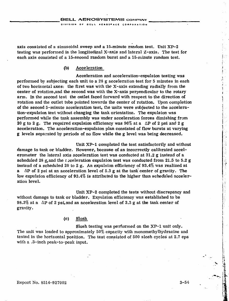
BELL AEROSYSTEMS COMP"'NY ------------------ ------------------DIVISION OF' DEi-I,. AEaOS"ACE CORPORATION
. axis consisted of a sinusoidal sweep and a 15-minute random test. Unit XP-2 testing was performed in the longitudinal X-axis and lateral Z-axis. The test for each axis consisted of a IS-second random burst and a 15-minute random test.
(b) Acceleration
Acceleration and acceleration-expulSion testing was performed by subjecting each unit to a 28 g acceleration test for 5 minutes in each of two horizontal axes: the first was with the X-axis extending radially from the center of rotaUon,and the second was with the X-axis perpendicular to the rotary arm. In the second test the outlet faced forward with respect to the direction of rotation and the outlet tube pointed towards the center of rotation. Upon completion of the second 5-minute acceleration test, t!le units were subjected to the acceleration-e.xpulsion test without changing the tank orientation. The expulsion was performed while the tank assembly was under acceleration forces dimishing from 20 g to 2 g. The required expulsion efficiency was 96% at a tiP of 2 psi and 2 g acceleration. The acceleration-expulsion plan consisted of flow bursts at varying g levels separated by periods of no flow while the g level was being decreased.
Unit XP-l completed the test satisfactorily and without damage to tank or bladder. However, because of an incorrectly calibrated accelerometer the lateral axis acceleration test was conducted at 31.2 g instead of a scheduled 28 g,and the ~ Jceleration expulsion test was conducted from 21.5 to 5.2 g instead of a scheduled 20 to 2 g. An expulsion efficiency of 93.4% was realized at a t.p of 2 psi at an acceleration level of 5.3 g at the tank center of gravity. The low expulsion efficiency of 93.4% is attributed to the higher than scheduled acceleratiOll level.
Unit XP-2 completed the tests without discrepancy and Without damage to tank or bladder. Expulsion efficiency was established to be 98.3% at a t.p of 2 psi, and an acceleration level of 3.3 g at the tank center of gravity.
(c) Slosh
Slosh testing was performed on the XP-l unit only. The unit was loaded to approximately 50% capacity with monomethylhydrazine and tested in the horizontal position. The test consisted of 500 slosh cycles at 2.7 cps with a .3-inch peak-to-peak input. .
Report No. 8514-927002 3-54
l i i !
! . . •
I I. f· ,. j i
I t
I
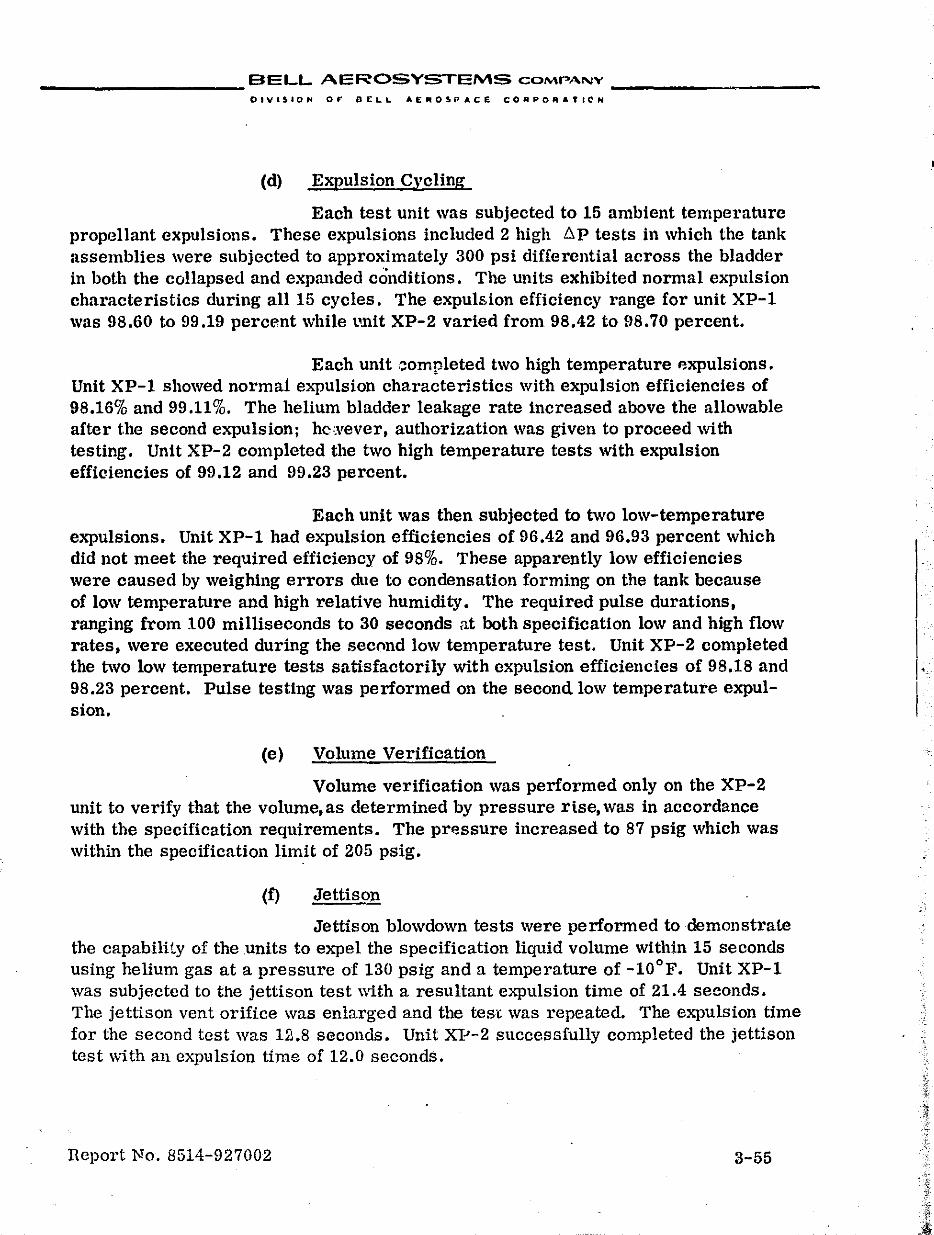
__________ BELL AEROSYSTEMS COMPANY _________ _
DIVISION Of:' DELL A[1III05PACE CORPO"""ICN
(d) Expulsion Cycling
Each test unit was subjected to 15 ambient temperature propr~llant expulsions. These expulsions included 2 high t,p tests in which the tank assemblies were subjected to approximately 300 psi differential across the bladder in both the collapsed and expanded conditions. The units exhibited normal expulsion characteristics during all 15 cycles. The expUlsion efficiency range for unit XP-1 was 98.60 to 99.19 percent while tmit XP-2 varied from 98.42 to fl8.70 percent.
Each unit ,::ompleted two high temperature p-xpulsions. Unit XP-1 showed norma! expulsion characteristics with expulsion efficiencies of 98.16% and 99.11%. The helium bladder leakage rate increased above the allowable after t.he second expulsion; hc~vever, authorization was given to proceed with testing. Unit XP-2 completed the two high temperature tests with expulsion efficiencies of 99.12 and 99.23 percent.
Each unit was then SUbjected to two low-temperature expulsions. Unit XP-1 had expUlsion efficiencies of 96.42 and 96.93 percent which did not meet the required efficiency of 98%. These apparently low efficiencies were caused by weighing errors due to condensation forming on the tank because of low temperature and high relative hUmidity. The required pulse durations, ranging from 100 milliseconds to 30 seconds at both specification low and high flow rates, were executed during the second low temperature test. Unit XP-2 completed the two low temperature tests satisfactorily with expulsion efficiencies of 98.18 and 98.23 percent. Pulse testing was performed on the second low temperature expulsion.
(e) Volume Verification
Volume verification was performed only on the XP-2 unit to verify that the volume, as determined by pressure ri.se, was in accordance with the specification requirements. The pressure increased to 87 psig which was within the specification limit of 205 psig.
(f) Jettison
Jettison blowdown tests were performed to demonstrate the capability of the units to expel the specification liquid volume within 15 seconds using helium gas at a pressure of 130 psig and a temperature of -10°F. Unit XP-1 was subjected to the jettison test with a resultant expulsion time of 21.4 seconds. The jettison vent orifice was enlarged and the tes\: was repeated. The expulSion time for the second test was Ul.8 seconds. Unit XJ:'-2 successfully completed the jettison test \vith an expulsion time of 12.0 seconds.
TIeport No. 8514-927002 3-55
__________ BELL AEROSYSTEMS COMPANY _________ _
DfvlStON 0,. DEL.&. AEROSPACE eORPO"ATION
The units successfully completed the qualification test series, with the specified variations. A detailed report on qualification testing is contained in Bell Report No. 8271-928037.
(2) Command Module Fuel Off- Limit Testing
After successful completion of the qualification test series the two test units were subjected to off-limit testing in accordance with the procedures specified in Bell Report No. 8271-928016. Unit XP1, which previously had completed the qualification test series, completed an additional 12 ambient expUlsions during off-limit testing prior to failure. Unit XP-2, after completing the qualification test series was subjected to random vibration in the longitudinal X-axIs for 5 minutes each at 21.0, 24.5, 28.0 and 31.5 g rms without failure during off-limit testing.
(a) Expulsion Cycling
Unit XP-1 completed a total of 12 off-limit ambient temperature expulsion cycles with expulsion efficiencies ranging from 98.8 to 99.2% and an average of 99.1%.
(b) Vibration
Unit XP-2 was subjected to random vibration in the longitudinal X-axis with the diffuser tube horizontal. The, input to the assembly started at 21.0 g rms, 50% above the qualification test (14.0 g rms),and was increased in 25% increments to 31.5 g rms (225% of 14.0 g rms) with runs of G minutes performed at each level. The tank assembly completed the tests at all input levels without damage to the tank or bladder.
The detailed results of off-limit testing are contained in Bell Report No. 827'1-928051.
(3) Command Moilule Oxidizer Qualification
Two command module oxidizer tanks were tested in accordance with the qualification test procedures contained in Bell Report No. 8271-928008, Revisions A and B.
Unit XP-1 completed the required test series which consisted of acceptance test, Vibration, slosh, acceleration/acceleration-expulsion, 15 ambient temperature propellant expulSions, 2 low-temperature expulsions, and 2 hightemperature expUlsions. Tank assembly deSignated XP-2 successfully completed
Report No. 8514-927002 3-56
,
-~
__________ BELL AEROSYSTEMS COMPANY _________ _
DIViSION OF BELl. A&R05PACE CORPORATION
the shell acceptrulCe test, pressure cycle test, tank assembly acceptance test; however, the bladder failed following the third ambient expulsion of the test series. Post-failure examination revealed that t!1e bladder had fabrication irregularities. The unit was refurbished with a new bladder and was deSignated unit XP-2A. This unit successfully completed the required test series which consisted of acceptance test, 15 ambient temperature propellant expulsions, vibration,acceleration/acceleration-expulsion, 2 low temperature expulsions, 2 high temperature expulsions, and volume verification.
(a) Vibration
Each unit was subjected to vibration testing in the longitudinal X-axis and a lateral axis with the units mounted in the horizontal position. Unit XP-l testing was performed in the longitudinal X-axis and lateral Y-axis. The test for each axis consisted of a sinusoidal sweep and a is-minute random vibration test. Unit XP-2A was tested in the longitudinal X-axis and lateral Z-axis. The test for each axis consisted of a is-second random burst and a is-minute random vibration test.
(b) Acceleration
Acceleration and acceleration-expulsion testing was performed by subjecting each unit to a 28 g acceleration test for 5 minutes in each of two hodzontal axes: the first was with the X-axis extending radially from the center of rotation and the second was with the X-axis perpendicular to the rotary arm. In the second test the outlet faced forward with respect to the diJ;ection of rotation and the outlet tube pointed towards the center of rotation. Upon completion of the second 5-mil1ute acceleration test the units were subjected to the accelerationexpulsion test without changing the tank orientation. The expulsion was performed while the tank assembly was under acceleration forces diminishing from 20 g to 2 g. The required expUlsion efficiency was 96% at a l'.P of 2 psi and 2 g acceleration.
Unit XP-l satisfactorily completed the testing without damage to tank or bladder. - However, the acceleration-expulsion test was conducted from 20.0 to 6.3 g instead of a scheduled 20 to 2 g. An expulsion efficiency of 92.2% was realized at a t,p of 2 psi at an acceleration level of 6.3 g at the tank center of gravity. The low expUlsion efficiency of 92.2% was attributed to the higher-thanscheduled acceleration level.
Unit XP-2A was tested without damage to tank or bladder; however, the acceleration test was conducted from 20.0 to 6.8 g rather than scheduled 20.0 to 2.0 g. Expulsion efficiency was determined to be 94.2% at a l'.P of 2 psi and an acceleration level of 6.8 g at the tank center of gravity.
Report No. 8514-927002 3-57
•
\ -
-,
.j-
tiM
__________ SELL AEROSYSTEMS COMPA.NY _______ • ___ _
DIVISION or D£L,..L AEROSPACE cORPO ..... TION
(c) Slosh
Slosh testing was performed on the XP-1 unit only with the unit loaded to approximately 50% capacity with nitrogen tetroxide. The test consisted of 500 slosh cycles at 2.6 cps with a .3-inch peak-to-peak input with the unit in the horizontal position.
(d) Expulsion Cvcling
Units XP-l and XP-2 were subjected to 15 ambient temperature expulsions and both units exhibited normal expulsion characteristics during all 15 cycles. Expulsion efficiency ranged between 98.61 and 98.85% for unit XP-1 and between 98.53 and 98.76% for unit XP-2A.
Each unit completed two low temperature expulsions. The resulting expulsion efficiencies for unit XP-1 were 97.49 and 97.840/0, which did not meet the required efficiency of 98%. These apparently low efficiencies were caused by a change in weight due to condensation forming on the tank because of low temperature and high relative humidity. The first low temperature test was pulsed and the required pulse durations were executed. Unit XP-2A completed the two low temperature tests satisfactorily with expulsio:n efficiencies of 98.33 and 98.03%; Pulse testing was performed and the required pulse-width durations were executed.
Each unit was subjected to two high temperature e:r,:ulsions and both showed normal expulsion characteristics during the tests. The expulsion efficiency for unit XP-1 was 96.18% and 98.89%. The efficiency for unit XP-2A was 92.40% and 91.68%.
(e) Volume Verification
Volume verification was performed on the XP-2A unit only to verify that the volume was in accordance with the specification requirements. The pressure increase to 80 psig was within the specification allowable of 205 psig. Test wlits XP-1 and XP-2A successfully completed the required test series ,with t.he slight eX'Plainable expulsion efficiency variations during acceleration-expulsion and low and high temperature expulsion testing. The detailed results of the testing are contajned in Bell Report No. 8271-928038.
(4) Command I>1:odule Oxidizer Off-Limit Testing
After successful completion of the qualification test series,
•
the two test units were subjected to off-limit testing in accordance with the procedures specified in Bell Report No. 8271-928016. Unit P1, which previously had completed
Report No. 8514-927002 3-58
'- ')
.. " , ;;
~ .;~
~.;-.-,
, ( .! , J
-,;' " , " "I
J .",--
g .'
__________ BELL AEROSYSTEMS COMPA.NY _________ _
OlVl510N OF DELL. AEIII:05PACE COIII:PORATION
the required qualification test series; completed an additional 50 ambient expulsions during off-limit testing without failure. Unit P2A, after completing the required qualification test series, was subjected to off-limit random vibration'in the longitudinal X-axis for 5 minutes each at 21.0, 24.5, 28.0 and 31.5 rms without failure.
(a) Expulsi011 Cycling ,
Unit Xp.:;lcompleted a total of 50 off .. limit ambient temperature expulsion cycles without failure. The expulsion efficiency ranged from 98.9 to 99.8% with an average of 99.1%. All efficiencies were over the minimum requirement of 98%.
(b) Vibration
Unit P2A was subjected to random vibration in the longitudinal X-axis with the diffuser tube in the horizontal position. The input to the assembly started at 21.0 g rms (50% above the qualification test level of 14.0 g rms) with runs of 5 minutes performed at each level. The tank assembly completed the tests at all input levels without damage to the tank or bladder.
The detailed results of off-limit testing are contained in Bell Report No. 8271-928052.
(5) Command ModtJl~_ Design Substantiation Testing
The design substantiation test program was a supplemental engineering test program considered necessary because of the limited test data available regardil1g the performance capabilities of the command module fuel and oxidizer configurations. The purpose of the test program was to detennine the operational limits of the quahfication configuration tank design under various test environments and to establish limits and criteria by which remaining bladder life could be predicted, that is, total bladder cycle life and curves of helium and nitrogen leakage rates versus number of operational cycles. The methods and test procedures used for this program were in accordance with the procedures established for use in the qualification test program and as specified in Bell Report No. 8271-928030.
Thirteen command module positive expulsion propellant tank assemblies were subjected to the test series which consisted of propellant expulsion and gas cycle te['!ting. The six fuel and seven OXidizer tank assemblies completed the test program with three units failing to complete the scheduled test series. The quantity of hardware used in the testing was minimized by using four tank
Report No. 8514-927002 3-59
.'
__________ BELL AEROSYSTEMS COMPANY _________ _
DIVISION or DELI. Ar::ROSPACE CORPORATION
assemblies, 2 fuel and 2 oxidizer, and refurbist.ing them with new bladders as required to complete the test series. The required tests were as follows:
• Propellant ExpulSion, ambient temperature
• Propellant E:lI.llulsion, cold temperature
• Propellant Expulsion, high temperature
• Gas Expulsion, ambient temperature, low t.P
• Gas ExpulSion, ambient temperature, high t.P
The propellant expulsions were performed using nitrogen tetroxide in the oxidizer units and monomethylhydrazine in the fuel \mits. Dry cycle testing was performed with nitrogen as the simulated propellant and pressurant. The failure criteria were patterned after the criteria used for qualification testing except that the allowable nitrogen leakage rate of the bladder was doubled to permit acquiring additional cycle life and leakage rate data prior to removing a unit from test.
Propellant expulsion testing was conducted on 4 fuel and 5 OXidizer tank assemblies in the horizontal attitude using normal operating pressure and flow rates. The original plan, which consisted of the following items, was executed with only minor changes:
Cycle Life - Establish cycle life capability at the required temperatures by performing te~ts as follows:
• Ambient temperature - subject 2 oxidizer and 1 fuel unit to a total of 35 expulSions each.
• Low temperature - subject 1 oxidizer and 2 fuel units to a total of 12 expulsions each.
• High temperature - subject 2 oxidizer and 1 fuel unit to a total of 12 expulSions each.
Expulsion Efficiency - Demonstrate the following efficiencies during life cycle testing:
• .Demonstrate an expulsion efficiency of 98% at a t.p of 2 psi at the high flow rate for all expulsions except the higl~ temperature oxidizer where the efficiency requirement is 93%.
Report No. 8514-927002 3-60
':;.
__________ BELL AEROSYSTEMS COMPANY __________ ' •.. _
DIVISION OF DE ....... AEROSPACE CORPORATION
• Demonstrate an expulsion efficiency of 99% at shutdown at the low flow rate for all expulsions by performing an additional "squeeze" on the bladder. This test was not required if an efficiency of 99% was achieved at the high flow rate.
Leakage Tests - Establish criteria for predicting remaining bladder life by performing helium and nitrogen bladder leakage tests alternately throughout the testing.
(a) Ambient Temperature Expulsions
The test plan required subjecting one fuel and two oxidizer units to a total of 35 expulsions at a temperature of 70°F on each unit. Essentially, this plan was completed as scheduled.
Unit F A1 completed the 35 scheduled expulsions with an expulc;ion efficiency mean value of 98.7%. The secondary expulSion at the low flow rate was required on four of the 35 expulsions. Unit OA1 exceeded planned requirements by completing 40 ambient propellant expulsions,whereas 35 were originally scheduled. The additional five were performed to evaluate an increasing leakage rate trend. The expulsion efficiency mean value was 98.5% and the range of 97.9 to 98.8% demonstrated compliance with the required 98% level. The low flow expulsion efficiency mean value was 99.1%. The low flow expulsion was not performed on 9 cycles where the high flow rate had demonstrated the 99% expulsion efficiency.
Unit OA2 completed the 35 scheduled ambient propellant expulsions with expulsion efficiencies above the required 98% for all 35 cycles. The low flow expulsion efficlency mean value of 99.1% was abo.ve the required 99%. The low flow was not performed on 19 expUlsions since a 99% expulsion efficiency was demonstrated at high flow shutdown.
(b) High Temperature Expulsion
The test plan required subjecting one fuel and two oxidizer units to a total of 12 expulsions at a temperature of 105 OF on each unit.
Unit FlU successfully completed the scheduled 12 high ·temperature expulsions with expulsion efficiencies at the high flow rate shutdown exceeding 99% on each cycle.
Report No. 8514-927002 3-61
."
__________ BELL AEROSYSTEMS COMPANY _________ _
DIVISION Or OEL'" AEROSPACE CORPORATION
Unit OH1: completed 7 of the 12 scheduled high temperature expulsions. Leakage rates were above the allowable limits after expulsion No.3 ,but testing was continued to obtain cycle life versus leakage rate data. All high flow rate efficiencies exceeded the required 93%, with the mean value 95.4% and the range 93.6 .to 98.8%. The low flow expulsion was required on 6 cycles and all were greater than the specified 99%. The mean value was 99.5% and the range was 99.2 to 99.9%.
Unit OH2 completed the scheduled 12 high temperature expulsions: however, leakage rate exceeded the allowable limit after expulsion No. 10. The expulsion efficiency mean V(l.LUe was 97.6% and the range of 95.8 to 98.9% showad performance greater than the required 93% for all cycles. The low flow expulsion was performed on 10 cycles and the expulsion efficiency mean was 99.6% with a range of 99.5% to 99.8%.
(c) Low Temperature Expulsions
The test plan required subjecting two fuel and one oxidizer unit to a total of 12 expulsions, each at a temperature of 35°F.
Unit FCI completed 10 of the scheduled 12 cold propellant expulsions. The leakage test rates following expUlsions No.8, 9, and 10 were above the allowable limits. The expulsion efficiency mean value was 97.9% and the range was 96.7 to 98.4%. The low flow mean expulsion efficiency was 99.0% with a range of 98.6 to 99.2%. The low efficiency which resulted during 5 expulsions can be attributed to weighing error caused by condensation on the cool tank from the humid atmosphere.
Unit FC2 completed the scheduled 12 cold propellant expulsions. The expulsion efficiency mean was 97.3%; range was 95.5 to 98.3%. The low flow rate expulsion efficiency mean value was 98,6% with a range of 97.9 to 99.6%.
Report No. 8514-927002
.~. .
•
3·-62
;
__________ BELL AEROSYSTEMS COMPANY _________ _
DIVISION OF DELL. AEROSPACE CORPORATION
Unit OC1: successfully completed 7 of the scheduled 12 cold propellant expulsions. The expulsion efficiency mean value was 98.2% with a range of 97.8 to 98.3%. The low flow rate expuision efficiency mean was 98.9% with a range of 98.5 to 99.1 % for the 5 expulsions where low flow was required.
(d) Gas Cycle Testing
Gas cycle testing was performed on four test units. The purpose of the testing was to determine the life cycle capability of the tank assemblies without the influence of propellants, and to obtain data on helium and nitrogen leakage rates versus number of cycles. Each test unit completed 50 cycles as scheduled, and nitrogen and helium bladder leakage tests were performed alternately on each fourth cycle. The testing was performed in the temperature range of 65 to 95°F with an expulsion pressure of 287 psig. Nitrogen gas was used as the pressurant and as "simulated propellant" for the liquid side of the bladder.
(e) Low t"p Tests
One fuel and one oxidizer unit were subjected to the low t"p test series. The test was designed to subject the bladder to the same action as an expulsion without using a test liqUid. Each expulsion was terminated at an indicated t"p of 3.5 to 4 psi. Units OGL and FGL completed the scheduled 50 cycles, with helium leakage rates within the specified limits throughout the testing.
(f) High t"p Tests
One fuel and one oxidizer unit were subjected to the high t"p test series. The test was designed to subject the bladder to a t,.P of 287 psi at the end of the cycle. Units OGH and FGH completed the scheduled 50 cycles, with helium and nitrogen leakage rates within the required limits throughout the test series.
(g) Conclusions
No direct correlation could be made between helium leakage rate and nitrogen leakage rate data. The helium leakage test provides the necessary sensitivity to accurately monitor changes in bladder permeation characteristics; however, there appears to be no way to relate bladder leakage rate to number of bladder cycles to preclict subsequent bladder service life or failure. The detailed results of the design substantiation testing are contained in Bell Report No. 8271-928039.
Report No. 8514-927002 3-63
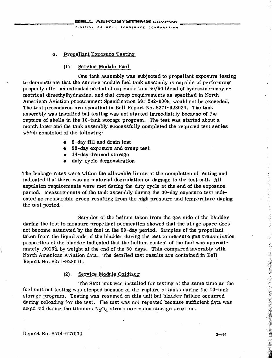
__________ BELL AEROSYSTEMS COMPANY _________ _
OIVISION OF' Dt:.L'- AEROSPACE CORPORATION
c. Propellant Exposure Testing
(1) Service Module Fuel
One tank assembly was subjected to propellant exposure testing to demonstrate that the service module fuel tank assmnbly is capable of performing properly afte' an extended period of exposure to a 50/50 blend of hydrazine-unsymmetrical dimethylhydrazine, and that creep requirements as specified in North American Aviation procurement Specification Me 282-0008, would not be exceeded. The test procedures are specified in Bell Report No. 8271-928024. The tank assembly was installed but testing was not started immediately because of the rupture of shells in the 10-tank storage program. The test was started about a month later and the tank assembly successfully completed the required test series ·;.-M0h consisted of the following:
• a-day fill and drain test • 30-day exposure and creep test • l4-day drained storag~ • duty-cycle demonstration
The leakage rates were within the allowable limits at the completion of testing and indicated that there was no material degradation or damage to the test unit. All expulsion requirements were met during the duty cycle at the end of the exposure period. Measurements of the tank assembly during the 30-day exposure test indicated no measurable creep resulting from the high pressure and temperature during the test period.
Samples of the helium taken from the gas side of the bladder during the test to measure propellant permeation showed'that the ullage space does not become saturated by the fuel in the 30-day period. Sainples of the propellant taken from the liqUid side of the bladder during the test to measure gas transmission properties of the bladder indicated that the helium content of the fuel was approximately .0016% by weight at the end of the 30-days. This compared favorably with North American Aviation data. The detailed test results are contained in Bell Report No. 8271-928041.
(2) . Service Module Oxidizer
The SMO unit was installed for testing at the same time as the fuel unit but testing was stopped because of the rupture of tanks dUring the 10-tank storage program. Testing was resumed on this unit but bladder failure occurred during reloading for the test. The test was not repeated because sufficient data was acquired during the titanium N204 stress corrosion storage program.
Rcport No. 8514-927002 3-64
=
__________ BELL AEROSYSTEMS COMPANY __________ _
DIVISION 0,. DCLL. A£"OS~.CE t;O""OAATION
d. Propellant Storage
The N204 ten-tank storage. fuel (MMlI and 50/50 blend) storage, and the :Lesulting activity under the titanium - N204 stress corrosion programs originated and were administered as part')f the Bell Model 8271 Apollo Tankage Program. Because of the magnitude and indu.,try-wide impact of the stress corrosion investigation, it is covered separately in this section as an assot.:lated program.
. "
Report No. 8514-927002 3-65
.
__________ BELL AEROSYSTEMS COMPA.NV __________ _
DIVISION OF OEL.L A£MOIPACE COAPO"ATION
B. MODEL 8339 LM RCS TANKAGE PROGRAM \
1. INITIAL DESIGN
In February 1964, initial go-ahead was received from Grumman Aircraft Engineering Company to supply positive expulsion tankage for the Lunar Module RCS propulsion system which uses 50/50 blend fuel and N204 oxidizer. The resulting program is shown in Figure 111-6.
The design was governed by a contractual requirement of commonality to the Apollo RCS tankage with limited exceptions based on specification requirements or customer preference. Consequently, the initial design released in April 1964 was identical to that of Apollo with the follOWing exceptions:
• The cylindrical length was increased to accommodate the greater volume of propellant required.
• Tank shell thiclmess was altered to comply with the pressllre and dynamic requirements of GAEC.
• The liquid bleed tube was incorporated into the initial diffuser design. This was not yet common with Apollo because ,although this addition had been proposed by Bell for the Apcllo tanks, it was not approved by North American until June 1964 for service module tanks and December 1964 for command module t;mks.
• Diffuser outlet, bleed tube, and helium inlet port fittings were 304L stainless steel with tube fittings installed.
• Diffuser and propellant outlet were fabricated from 3/4-inch O.D. tubing with the outlet tube having a wall thickness of 0.020 inch.
Procurement activity was started for shells, bladders and diffuser material in April 1964, .
2. DESIGN DEVELOPMENT
a. Diffuser Assembly
Fabrication of diffuser assemblies was initially delayed because of difficulty in obtaining 304L stainless tubing that met GAEC specification requirements. The tubing was received in August 1964,and fabrication of diffusers proceeded.
Report No. 8514-927002 3-66
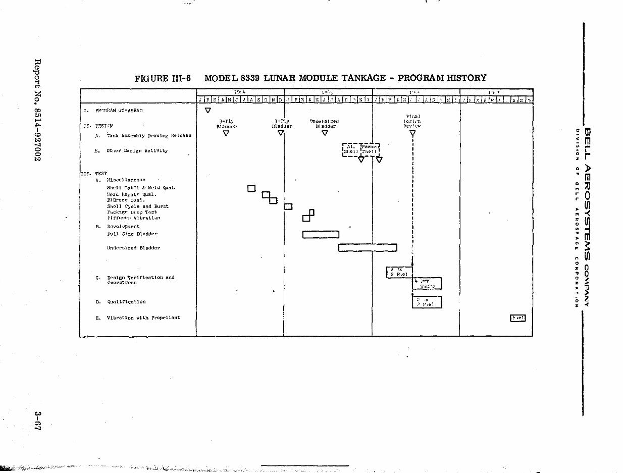
-------------------
!:d Q ';:l o Ii ..... Z o • (Xl <:.n ..... II'I
<.0 ~ -'I o o t..:.
~ I :l) -'I
:":.;:;';,;'-.;-.. ;~f'~"'-""'·'- 'iI>'h"',-
, .. ,..'
FIGURE m-6 MODEL 8339 LUNAR MODULE TANKAGE - PROGRAM HISTORY
: '".,1, 1 0 (,: i '). , . 1 j. 7
. ; I i' I :., I A !r·lI J I < I;, I s 10 I N Iv .1 I F I" I. I f1 1.1 I.' I A I r I ,I" I I .' I. I" I d ,., I· I· I;· I" I' /:; 1 , .' I, I" I;, 1 d., I. 1 A S , I. ppnGHAr-t GO- ABEll:'! '\l
Ft r,r; 1 3-Pl:; l-Ply !}ndern I::ed lct.'II'r.
Jr. fESIJN Bl.:ldder Inad'Jer Bladder flel::"","
n. ';:ank ,\ssembly llruwlng Release '\l '" '\l 'Y , r ,\i:-TrC'C,H.::J I
at:.c!' !Nolgn ActlvitJ I b. f,bell ~hell' I L.:; ___ Q_' ~ I : I
II!. TEST I I
A. lUn..:ellaneou3 I Shell Hat'l &: Weld Qual. D I
I Held Repair qual. Cb I Bl.Draze qUal. I Shell ~ycle and Burnt 0 I
cP ,
I'f1ck;u~(> !;I'op Tf!ot , PI!TIHWI'VllJrrttlun I ,
n. Tlevc!;:'pr.tent I Full Sho Dladuct' I I I
I I
Undp.rolzed Bisouer I .J , ,
c. D<'ole;n 'Verification and ~~~ ~~l'.J Ovcrrstrcss I T'Jl:'~..:' .
n. Qualification m ,> Ple' ,
E. Vllll'ot1on wlLh Pt'opt>llant
--' a
- .. _- - -- ---- ... _--- ._--
.. ,."."-" .,~". '-"""""'.",0. .,:;~,.'-liIi,: ,I" ' ,
~ ID ~ m :: r ~ r o ) ~ m ~ '" ~ 0 • Ul ... -< ~ ~ : m :;: ~ n Ul ~ n .. 0 ~ ~ • "(l
~ " ;; l z <
__________ BELL AEROSYSTEMS COMPA.NY _________ _
DIVISION or D£L.L AEROSPACE CORPORATIOH
In November 1964, five propellant outlet assemblies were tested to qualify the Bi-braze joint. All of the units successfully completed the testing which included proof pressure, helium leakage, temperature cycle, fatigue cycle, vibration, helium leakage, burst, and shear strength tests. This testing is reported in detail in Bell Report No. B339-910001.
Meanwhile, during diffuser fabrication, cracking was experienced in the propellant bleed tube in the area of weldment to the outlet tube. This was caused by the boron content of the 304L stainless. This problem was alleviated by limiting the boron content to 0.003%. Additional problems were encountered with the Bi-braze joint. It was difficult to obtain a good coating of the 31)4L outlet tube with aluminum during the Bi-braze process. Also the tube corroQed in the vicinity of the Bi-braze joint because of sensitization from the brazing process. As a result, Bell recommended the use of 347 stainless tubing on the basis of its reSistance to sensitization and demonstrated success on the Apollo Command and Service Module assemblies. Grumman approved this recommendation and the change was made.
Diffuser vibration testing was conducted on one fuel and one oxidizer diffuser assembly to establish structural adequacy of these components. Each diffuser was tested in the longitudinal and one lateral axis at qualification vibration test levels and up to 1.5 qualification levels. Both tubes successfully passed the testing which is reported in detail in Bell Report No. 833Q-928004.
In April 1965, the tank assembly desigu was changed to require cutoff of outlet tube, bleed tube and helium inlet port tube prior to delivery to Grumman. A few tanks, however, were delivered with tube fittings for breadboard testing.
h. Tank Shell
(1) Structural Analvsis
Structural and preliminary dynamic analyses were performed in April 1964 to verify the shell deSign and are reported in detail in Bell reports 8339-941001 and 8339-941002. The preliminary dynamic analysis was conducted in conjunction with similar analyses performed at Grumman in order to determine the dynamic response of the tanks in the LM dynamic environments, not only on rigid supports but also on supports which incorporated the flexibility factors of the vehicle moun ting brac kets .
Report No. 8514-927002 :1-613
I
__________ BELL AEROSYSTEMS COMPANY __________ _
DIVISION OF OCLIw AEROSPACE CORPOAATION
(2) Process Qualification
The LM tank shells are of the same materials and construction as the Apollo shells except for cylindrical length and shell thickness. Therefore, to expedite the test program, the first 20 shells were fabricated in accordance with Apollo material and process controls while qualification of material and welding processes ·were being performed to Grumman specification requirements. This quaUfication was completed in August 1964. Subsequent problems encountered with weld mismatch on shells were solved by changing the weld backup ring. This resulted in a penalty weld qualification test in November 1954. The twenty-first and all subsequent shells (including all those of qualification and flight configuration) were fabricated to the LM specification requirements. A weld repair process for the shell was successfully qualified; however, no weld repair has been performed on any LM shell.
(3) Burst Test
Fatigue cycle and burst tests were performed on one fuel and one oxidizer shell in January 1965 to verify the structural adequacy of the "tank shell design early in the program.
A total of 3000 hydrostatic pressure cycles consisting of repeated series of 270 cycles from 0 to 180 psig, followed by 30 cycles from 0 to 250 psig, with a pressure rise time of 1.25 ±.25 seconds, was performed on each shell. This was followed by hydrostatic proof pressure test at 333 psig and a burst test. There was no permanent set at proof pressure. Burst pressures were 615 psig for the fuel shell and 818 psig for the oxidizer shell. These results compared favorably with theoretical values of 620 psig and 825 psig for the fuel and oxidizer shells, respectively. These values greatly exceeded the speCification requirement of 375 psig because of the design considerations necessary to meet the specified dynamic requirements.
(4) Vibration Testing
Vibration testing of one fuel and one oxi,jizer tank assembly was conducted in the period of May to August 1965. This testing was accomplished to check the vibration fixtures and test procedures and to determine the structural adequacy of the tank assemblies, vehicle mounting brackets, and propellant gaging system under qualification level vibration inputs. original design full-size bladders were used for these tests to establish the structural adequacy of the tankage and support system early in the program. Each tank was subjected to sinusoidal and random vibration in each of the three orthogonal axes. The tanks were loaded to specification propellant volume with substit·ute liquids. The fuel was simulated
Rcport No. 8514-927002 3-69
.',~,
J?: .~.
. :~~. \1.
I .
j": .. ~ ....
I ',,:'I!
__________ BELL AEROSYSTEMS COMP"""'V _________ _
DIVISION OF BELL AER05PACE CORPORATION
using a mixture of 1.06 parts of isopropanol to 1.0 part distilled water by \veight. Freon-TF mixed with 5% methanol by weight was used to simulate the oxidizer.
The fuel bladder failed after completion of X-axis sine and random and Y-axis sine vibration. An equipment problem during the latter test resulted in a Sf'vere overtest cc-ndition which contributed to bladder failure. The bladder was replaced and the Y- and Z-axis testing was completed. The oxidizer tank completed all the testing without incident. The fuel and oxidizer tank assemblies, fixtures, and vehicle mounting brackets proved satisfactory. The Gianini propellant gaging blankets did not fail although they showed crazed areas around the screws used to hold the halves of the blanket together. All bladders used for the test were severely damaged; however, only one failed and this was apparently cau!?ed by the overtest conc4tion. Grumman was requested to re-examine the projected mission Vibration environments from the standpOint of reducing the qualification level vibration requirements.
(5) Alternate Designs
When the problem of titanium stress corrosion with N204 occurred on Apollo, Grumman requested that Bell initiate a design effort for an alull.linum tank shell. Three aluminum alloys (6061, 2219 and 2014) were investigated for pOSSible use' and preliminary shell drawings were made. This effort was stopped in November 1965 when internal peening of titanium shells was found to be an effective deterrant of stress corrosion with N204' Requirements for glass bead peening of shells were then established in December 1965, and three oy;, ,>:er and three fuel tank shells were sent to NASA Langley Research Center for peeli~:~. After peening, these shells were returned to Bell and subsequently used in tank assemblies which were delivered to Grumman. The subsequent adoption of N204 with a controlled NO content as an effective stre'ss corrosion inhibiting measure precluded further use of peened tank shells on the LM RCS tankage.
c. Bladder
(1) Initial Design and Test
In conformance with the commonality concept, the original bladder design released in April 1964 was the 3 mil 3-ply configuration which was the current Apollo design. However, procurement of this configuration was stopped in June 1964 because of problems on the Apollo program. In December 1964, after the full size 6 mil single-ply bladder was adopted for Apollo with successful testing, the LM design was changed to this configuration and bladder procurement was again initiated. t
Report No. 8514-927002 3-70
__________ BELL AEROSYSTEMS COMPANY _________ _
DiViSION OF DELL AEROSPACE CORPORATION
In March 1965, the first single-ply full size bladder was tested in a plexiglnss tank to determine if the increased length over that of the Apollo tank would affect bladder behavior. One expulsion was made in the vertical flange-down attitude on an oxidizer bladder using Freon-TF as the expulsion medium. After completion of the expulsion, the bladder was re-expanded and the tank filled to capacity in preparation for the next expulsion. At this point the bladder failed in the top (retainer) hemisphere. The failure consisted of two small slits in the retainer hemisphere. These slits were in areas of numerous striations and stress cracks. There was also a small puncture in the cylindrical section caused by a foreign particle on the outside of the bladder.
A thorough investigation of the stress failure in the upper hemisphere of the bladder was conducted. The failure mechanism was identified as biaxial stress imposed during post-expulsion re-expansion of the bladder. This condition resulted from the fact that as liquid is expelled from the tank the bladder material is displaced downward and, at the end of the expulsion, becomes trapped in the bottom of the tank in the form of deep folds. During subsequent gas re-expansion of the bladder the cylindrical section expands first and engages the tank wall. In the case of the LM tanks the length/diameter ratio resulted in bladder-to-wall friction forces exceeding the available lifting forces provided by bladder internal pressure. This resulted in yielding of the top hemisphere of the bladder. Bladder fabrication was stopped in April 1965, pending resolution of this problem.
During the investigation, additional. plexiglass tank tests were conducted in which various techniques, such as simultaneously pressurizing both inside and outside of the bladder, were attempted in an effort to effect bladder recovery. None resulted in complete recovery unless the tank assembly was inverted prior to expansion. The use of lubricants between the bladder and tank shell was also unsuccessful.
Results of additional tests disclosed that expulsion of not more than 50% of the loadable volume of propellant resulted in satisfactory post-expulsion bladder recovery. As a result, a limited number of tanks with full size bladders were delivered to Grumman for limited testing pending resolution of the positioning problem.
.(2) DeSign Development
As a result of the bladder failure,a bladder deSign and development program was initiated in April 1965. The program was conducted simultaneously along two parallel lines of effort, bladder redesign and adaptation of existing hardware and servicing procedures.
Hcport No. 8514-927002 3-71
:~
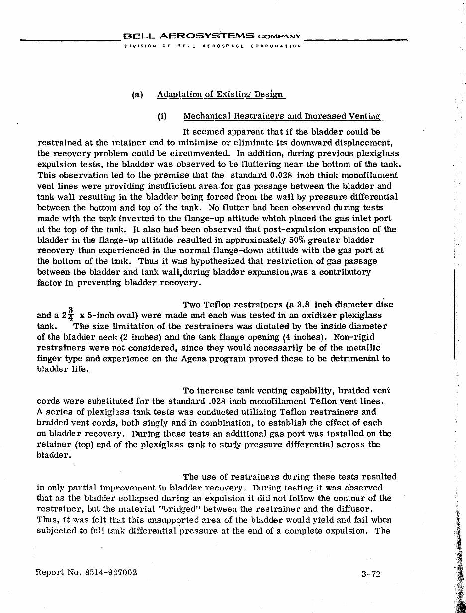
__________ BELL AEROSYSTEMS COMPANY _________ _
DiViSION OF BELL AEROSPACE CORPORATION
(a) Adaptation of Existing Design
(i) Mechanical Restrainers and Increased Venting
It seemed apparent that if the bladder could be restrained at the retainer end to minimize or eliminate its downward displacement, the recovery problem could be circumvented. In addition, during previous plexiglass expUlsion tests, the bladder was observed to be fluttering near the bottom of the tank. This observation led to the premise that the standard 0.028 inch thick monofilament vent lines were providing insufficient area for gas passage between the bladder and tank wall resulting in the bladder being forced from the wall by pressure differential between the bottom and top of the tank. No flutter had been observed during tests made with the tank inverted to the flange-up attitude which placed the gas inlet port at the top of the tank. It also had been observed that post-expulsion expansion of the bladder in the flange-up attitude resulted in approximately 50% greater bladder recovery than experienced in the normal flange-down attitude with the gas port at the bottom of the tank. Thus it was hypothesized that restriction of gas passage between the bladder and tank wall, during bladder expansion ,was a contributory factor in preventing bladder recovery.
a Two Teflon restrainers (a 3.8 inch diameter disc and a 2:{ x 5-inch oval) were made and each was tested in an oxidizer plexiglass tank. The size limitation of the restrainers was dictated by the inside diameter of the bladder neck (2 inches) and the tank flange opening (4 inches). Non-rigid restrainers were not considered, since they would necessarily be of the metallic finger type and experience on the Agena program proved these to be detrimental to bladder life.
To increase tank venting capability, braided venl; cords were substituted for the standard .028 inch monofilament Teflon vent lines. A series of plexiglass tank tests was conducted utilizing Teflon restrainers and braided vent cords, both singly and ill combination, to establish the effect of each on bladder recovery. During these tests an additional gas port was installed on the retainer (top) end of thE! plexiglass tank to study pressure differential across the bladder.
The use of restrainers during these tests resulted in only partial improvement in bladder recovery. During testing it was observed that as the bladder collapsed during an expulsion it did not follow the contour of the restrainer, hut the material "bridged" between the restrainer al1d the diffuser. Thus, it was felt that this unsupp~rted area of the bladder would yield and fail when subjected to full tank differential pressure at the end of a complete expulsion. The
Report No. 85l4-fJ27002 3-72
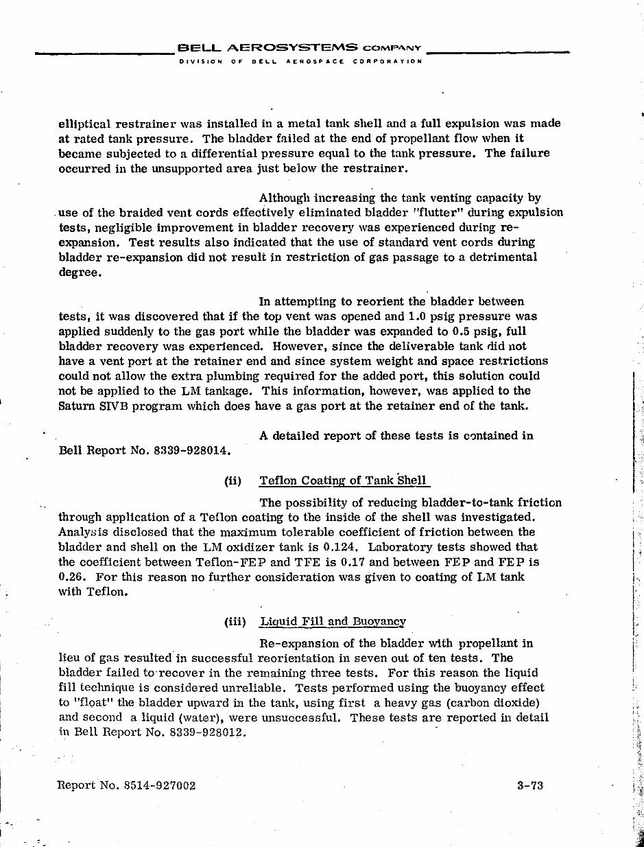
__________ BELL AEROSYSTEMS COMPANY __________ _
DIVISION or DEL.L. AEROSPACE CORPORATION
elliptical restrainer was installed in a metal tank shell and a full expulsion was made at rated tank pressure. The bladder failed at the end of propellant flow when it became subjected to a differential pressure equal to the tank pressure. The failure occurred in the unsupported area just below the restrainer.
Although increasing the tank venting capacity by ,use of the braided vent cords effectively eliminated bladder "flutter" during expulsion tests, negligible improvement in bladder recovery was experienced during reexpansion. Test results also indicated that the use of standard vent cords during bladder re-expansion did not result in restriction of gas passage to a detrimental degree.
In attempting to reorient the bladder between tests, it was discovered that if the top vent was opened and 1.0 psig pressure was applied suddenly to the gas port while the bladder was expanded to 0.5 psig, full bladder recovery was experienced. However, since the deliverable tank did 110t have a vent port at the retainer end and since system weight and space restrictions could not allow the extra plumbing required for the added port, this solution could not be applied to the LM tankage. This information, however, was applied to the Saturn SIVB program which does have a gas port at the retainer end of the tank.
A detailed report of these tests is c'Jntained in Bell Report No. 8339-928014.
(ii) Teflon Coating of Tank 'Shell
The possibility of reducing bladder-to-tank friction through application of a Teflon coating to the inside of the shell was investigated. Analysis disclosed that the maximum tolerable coefficient of friction between the bladder and shell on the LM oxidizer tank is 0.124. Laboratory tests showed that the coefficient between Teflon-FEP and TFE is 0.17 and between FEP and FEP is 0.26. For this reason no further consideration was given to coating of LM tank with Teflon.
(iii) Liquid Fill and Buoyancy
Re-expansion of the bladder with propellant in lieu of gas resulted'in successful reorientation in seven out of ten tests. The bladder failed to'recover in the remaining three tests. For this reason the liqUid fill technique is considered unreliable. Tests performed using the buoyancy effect to "float" the bladder upward in the tank, using first a heavy gas (carbon dioxide) and second a liquid (water), were unsuccessful. These tests are reported in detail ill Bell Report No. 8339-928012.
Report No. 8514-927002 3-73
•
.. ;~-"
17 -
I .. I ;
I' I'
I' i I~ ,
I
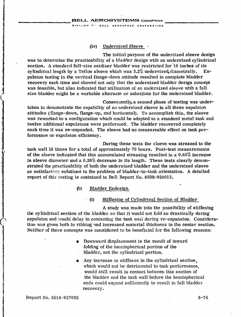
, )
'.
__________ BELL AEROSYSTEMS COMPANY _________ _
DIVt:'ION r.. DE~L AEROSPAce CORPORATION
(iv) Undersized Sleeve .
The initial purpose of the undersized sleeve design was to determine the practicability of a bladder design with an undersized cylindrical section. A standard full-size oxidizer bladder was restricted for'19 inches of its cylindrical length by a Teflon sleeve which was 3.2% undersized,c!lametrally. ExpulSion testing in the vertical flange-down attitude resulted in complete bladder recovery each time and showed not only that the undersized bladder design concept was feasible, but also indicated that utilization of an undersized sleeve with a full size bladder might be a workable alternate or substitute for the undersized bladder.
Consequently, a second phase of testing was undertaken to demonstrate the capability of all undersized sleeve in all three expulSion attitudes (flange-down, flange-up, and horizontal). To accomplish this, the sleeve was reworked to a configuration which could be adapted to a standard metal tank and twelve additional expulsions were performed. The bladder recovered completely each time it was re-expanded. The sleeve had no measureable effect on tank performance or expulsion efficiency.
During these tests the sleeve was stressed to the tank wall 16 times for a total of approximately 70 hours. Post-test measurements of the sleeve indicated that this accumulated stressing resulted in a 0.65% increa:se in sleeve diameter and a 0.26% decrease in its length. These tests clearly demonstrated the practicability of both the undersized bladder and the undersized sleeve as satisfactcTY solutions to the problem of bladder-to-tank orientation. A detailed report of this testing is contained in Bell Report No. 8339.-928013.
(b) Bladder Redesign
. (i) Stiffening of Cylindrical Section of Bladder
A study was made into the possibility of stiffening the cylindrical section of the bladder so that it would not fold so drastically during
. ...... expulsion and would delay in contacting the tank wail during re-expansion. Consideration was given both to ribbing ffild increased material thickness in the center section. Neither of these concepts was considered to be beneficial for the following reasons:
• Downward displacement is the result of in\yard folding of the hemispherical portion of the bladder, not the cylindrical portion.
• Any increase in stiffness in the cylindrical section, which would not be detrimental to tank performance, would still result in contact between this section of the bladder and the tank wall before the hemispherical ends could expand sufficiently to result in full bladder recovery.
Report No. 8514-927002 3-74
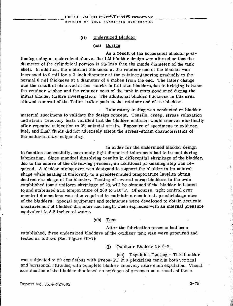
__________ BELL AEROSYSTEMS COMPANY ____ ~ ____ _
DIVISION OF DELL AEROSPA,CE CORPORATION
(ii) Undersized Bladder
(aa) Die_sign
As a result of the successful bladder positioning using an undersized sleeve, the LM bladder design was altered so that the diameter of the cylindrical portion is 2% less than the inside diameter of the tank shell. In addition, the material thiclmess at the retainer end of the bladder was increased to 9 mil for a 2-inch diameter at the retainer,tapering gradually to the normal 6 mil thickness at a diameter of 4 inches from the end. The latter change was the result of observed stress marks in full size bladders, due to bridging between the retainer washer and the retainer boss of the tank in tests conducted during the initial bladder failure investigation. The additional bladder thickn(:;ss in this area allowed removal of the Teflon buffer pads at the retainer end of the bladder.
Laboratory testing was conducted on bladder material specimens to validate the design concept. Tensile, creep, stress relaxation and strain recovery tests verified that the bladder material would recover elastically after repeated subjection to 2% Wliaxial strain. EJl.1losure of specimens to oxidizer, fuel, and flush fluids did not adversely affect the stress-strain characteristics of the material after outgassing. .
In order for the Wldersized bladder design to fWlction successfully, extremely tight diametral tolerances had to be met during fabrication. Since mandrel dissolving results in differential shrinkage of the bladder, due to the nature of the d:ssolving process, an additional processing step was required. A bladder sizing oven was designed to support the bladder in its natural shape while heating it uniformly to a predetermined temperature level,to obtain desired shrinkage of the bladder. Testing of several scrap bladders in the oven established that a Wliform shrinkage of 2% will be obtained if the bladder is heated to, and stabilized at, a temperature of 200 to 210°F. Of course, tight control over mandrel dimensions was also required to maintain a consistent, preshrinkage size of the bladders. Special equipment and techniques were developed to obtain accurate measurement of bladder diameter and length when expanded with an internal pressure equivalent to 8.2 inches of water.
(ab) Test
After the fabrication process had been established, three Wldersized bladders of the oxidizer tank size were procured and tested as follows (See Figure III-7):
ill Oxidizer Bladder SN 3-3
(aa) ExpulSion Testing - This bladder was subjected to 20 expuls{ons with Freon-TF in a plexiglass tank, in both vertical and horizontal nttitudes, with complete bladder recovery after each expUlsion. Visual examination of the bladder disclosed no evidence of stresses as a result of these
Report No. 8514-927002 3-75
.':
I {ji
.f;
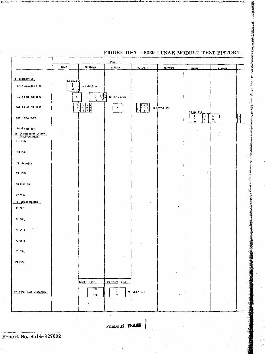
"" ·W "' ,"" .-..t
FIGURE I11-7 . 8339 LUNAR MODULE TEST HISTORY -
In!.
IUGUST SlPt{MblR or 100£tI IjQ~l"elrl DErE14!1[R JlNU'" " .II':! . I onClOP"I[HI "' ,,-' , SNJ~' OliDI1ER IIU,D. , , 11 LJPUL510NS
ID L :.',{
0 I ,
J~! ~ II! Uf''''LSION~ SHI-) OIlDlleR IlAD , "
l ',I H'U~I D 0'" $H4-) 01lDlZER ILAD A C II 1\ , 'H C 28 UPULSION5 1 15 1 2 I I, l. PlU IGLASS
I , I,' I , I Q[ Sf<Il-1 rUll SlAO • • " 11
SHIH fULL eLAO
I~ 11 fUEL
lUi FUlL
" DllPIZER
" fULL .
14 OllUlltR
15 FUEL
'" QUALlFICATlOII
• 1 FUEL .
'2 FUEL
" 01'0
'2 Olio
Pl FULL
.4 Futl
AUGUST l'7b7 S[PT[f<!BER 1%7
W m" UPULSIOII' IV PIlOPELLAtH 'IIBRAlIOIi
m 10
I ,
Report No. 8514-927002
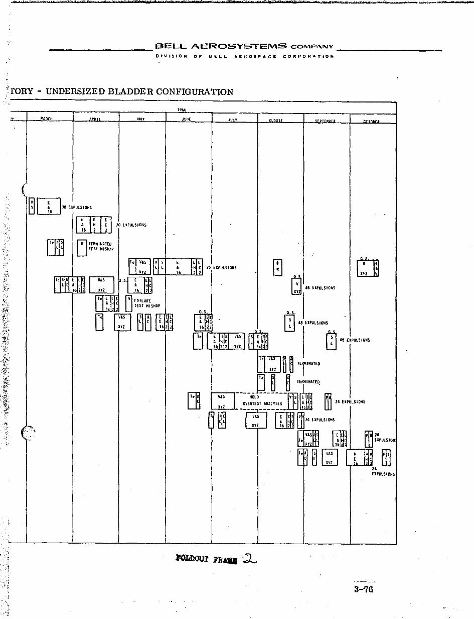
............ _. ~,(r ..... _'l"" ... · ... ~,"" .... ~ ... , "' .......... _ ..... , ..... ":'i" .• ,,,· "' .... .,;' ... '$""" .. ' ,", ... ,",'"", ... , ,"' .. '". · .. • .. ' .. ffi .. ···_' tlli· .... __ ~ ... , .. -·( .. !"' .... "'·."·,_._t" ... ,. ..... !"·,,''''Q .... _ .. ' ........ '~"~' ................. "''_'''''~" ..... ,~, ..... ___ .. '._ .......... __ ~-t.... t t
------------------ BELL AEROSYSTEMS COMP"NY
DIVISION OF 8£1.1. AEnOSPAC£ CORPORATION
:TORY - UNDERSIZED BLADDER CONFIGURATION
')0\. , '. '.
,Al'JllL ""
<-0w", PULSIONS
ro"T7"1 ~ I~ I i 1 10 UPU~SIONS 11. 1 2
~ uTI
rv1 TEIIMINATtD U TESt MISHAP
JUNr JULY
1" II ',',,' 111:,:1 'L ' I ~I [.1 r III ~b ldil 25 DPUL~IOMS
DfU&rn w't;=t=!J~~ '-'--t-"-....L!llJ
<t; ,
~ f;i' 4S UPULSIOH5 ~
ill .. "PuLSION'
m
~ ~
IS [lPUUIONS
,--.L. _____ -'-_____ .L. _____ ..l.. _____ ..1-_____ '"-_____ -'-_____ -'-_____ .J
3-76
__________ SEL.L AEROSVSTEMS COMPANY _________ _
DIVISION Of' BEL.l. AE"O'~ACt: COIIIPOIII"TION
tests. It should bc noted that regardless of the e""'PulsioI\ attitude" all loading and servicing of the LM tanks is performed in the vertical, flange-down,attitude to simulate vehicle use. Expulsion efficiency at a tank assembly 6P of 2 psi varied from 98.9 to 99.2% in the vertical attitude and from 90.8 to 93.5% in the horizontal attitude.
(ab) Slosh Testing - After expulsion testing, the bladder was subjected to slosh testing in a plexiglass tank to establish the fundamental slosh mode in the vl:rtical attitude when filled to 1/3 capacity and subjected to 0.1 g input perpendicular to the longitudinal axis. The fundamental slosh frequency was established at 3.2 cps. After a 500 cycle slosh endurance test, the bladder was examined with no observable evidence of stress damage.
As a result of the successful performance of this bladder, the remaining two bladders were assembled into prototype oxidizer tanks for testing.
au Oxidizer Bladder SN 2-3
This bladder was subjected to vibration in all three axes to the original LM dynamic requirements. This was followed by 18 propellant expulsions in the vertical attitude after which the bladder failed. The failure consisted of a 1/4-inch rupture in the flange end caused by biaxial stress. Measurement of the bladder disclosed that it was approximately 1/4-inch shorter than the tank shell and 3/8-inch shorter than its "as fabricated" length. This represented a one percent decrease in bladder length due to repeated flexure during test. This length decrease resulted in the bladder being stretched longitudinally in order to fill the tank shell after the cylindrical section engaged the tank wall.
Although the post-vibration bladder leakage tests showed that the bladder had not been functionally impaired by this test, it was removed from the tank prior to the expulsion test and examined for vibration damage. A number of stressed areas were found in the upper (retainer) hemisphere in the ullage portion of the bladder. Although these stresses were not nearly as severe as those found previously on the full size bladders, they appeared to be sufficiently damaging to adversely affect the subsequent cycle life of the bladder. As a result, Grumman revised the vibration requirements of the specification to more nearly approximate the mission requirements. All subsequent testing was performed to the new requirements.
(iii) Oxidizer Bladder SN 4-3
This bladder started testing simultanec\llsly with bladder SN 2-3 and was subjeJted to 20 propellant expulSions, vibration in all 3 axes to the new vibration rCt,"\l.irements, volume verification and an additional 5 eJ.'Pulsions prior to bladder failurc-
Report No. 8514-927002 3-77
.,-.
__________ BELL AEROSYSTEMS COMPANY _________ _
OlV'I510N 0' 0 ELI. AE.ROSP ACE COAPORATtON
(aa) propellant Expulsion Testing -The initial 20 expulsions consisted of 15 vertical at 70°F, 2 vertical at 35°F, 2 vertical at 105°F,and one horizontal at 70°F. Of the vertical tests, 10 were made in the flange-down attitude and 9 in the flange-up attitude. Ailer vibration and volume verification testing, one pulsed expulsion at 70°F was made in the vertical flangedown attitude followed by four horizontal tests, one at 105 OF and 3 at 35 of. During the last three expulsions, the helium pressurant gas was -20°F for the last 1~% of c;'tch e>q)ulsion and each expulsion was allowed to proceed until full tank assembly differential pressure was imposed across the bladder. During normal expulsion testing of a repetitive nature, the tests are automatically terminated when tank lIssembly 6, P reaches an indicated value of 3 to 4 psi. Expulsion efficiency of the tank in the vertical attitude exceeded 99% at a tank assembly 6,P of 2 psi which exceeded the specification requirement of 95%. In the horizontal attitude, however, ef(iciency ranged from 94.2 to 96.8% for the low temperature tests and 89.7% for the high temperature test. The lower efficiency in the horizontal attitude was expected and supported results obtained on the Apollo tank program. Grumman has since revised the speCification to lower the minimum horizontal expulsion efficiency to 87% and raised the maximum differential pressure at all attitudes to 2.5 psi.
(ab) Vibration Testing - The unit successfully completed all 3 axes of vibration in accordance with the new specifi-. cation requirements. The bladder was removed from the shell and examined both before and after vibration testing and exhibited no evidence of damage due to the vibration test. A few small stress areas which were found at each end of the bladder prior to Vibration test were not altered in appearance after the test.
(ttc) Volume Verification Test - This test was conducted to demonstrate compliance with the speCification requirement that the tank, when loaded with propellant to specified capacity at 65°F and pressurized to 25 psig, shallllot exceed an internal pressure of 130 psia when heated to a stabilized temperature of 100°F. The actual test pressure was 100 psia which was well within the specified limit.
(ad) Failure Analysis - The bladder failure was determined to have been caused by rolling of a tightly compressed buckled fold in an area previously weakened by bb .. xial stress. The tightly compressed buckled fold resulted from the last three low temperature horizontal expulsions being allowed to progress to full tank assembly differential pressure. "vIeasurements of the bladder disclosed that, like bladder SN 2-3, it had decreasetl one percent in length from the as-fabricated condition and was apprOximately 3/16-inch shorter than the tmlk shell. It was obvious that this was the cause of the biaxiaJ stress damage in both end., of the bladder which was identical to the damage experienced by bladder SN 2-3.
Report No. 8514-927002 3-78
! f I f !
! ! I ,
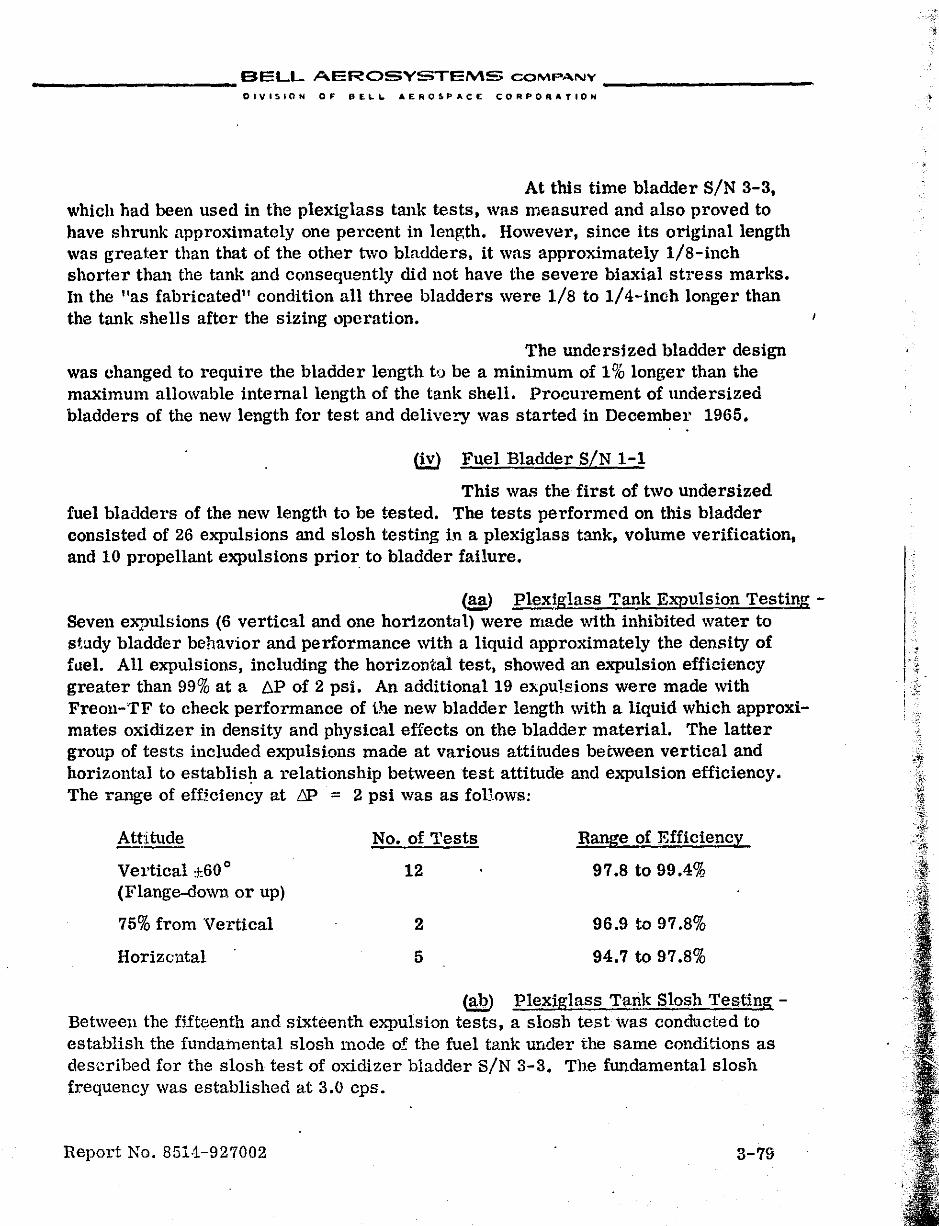
__________ BELL AEROSYSTEMS COMP,o.NV _________ _
DIVISION OF PEL~ AEROSPACE CORPORATION
At this time bladder SiN 3-3, which had been used in the plexiglass tank tests, was measured and also proved to have shrunk approximately one percent in lenJ!;th. HoweVl:lr, since its original length was greater than that of the other two bladders. it was approximately lIS-inch shorter than the tank and consequently did not have the severe biaxial stress marks. In the "as fabricated" condition all three bladders were lis to 1/4-inch longer than the tank shells after the sizing operation.
The undersized bladder design was changed to require the bladder length to be a minimum of 1% longer than the maximum allowable internal length of the tank shell. Procurement of undersized bladders of the new length for test and delivery was started in December 1965 • . .
(iv) Fuel Bladder SIN 1-1
This was the first of two undersized fuel bladders of the new length to be tested. The tests performed on this bladder consisted of 26 expulsions and slosh testing in a plexiglass tank, volume verification, and 10 propellant expulsions prior to bladder failure.
Caa) Plexiglass Tank Expulsion Testing -Seven expulsions (6 vertical and one horizontal) were made with inhibited water to study bladder behavior and performance with a liquid approximately the density of fuel. AU expulsions. including the horizontal test. showed an expulsion efficiency greater than 99% at a ~ of 2 psi. An additional 19 expulsions were made with Freoll-TF to check performance of the new bladder length with a liquid which approximates oxidizer in density and physical effects on the bladder material. The latter group of tests included expulSions made at various attitudes between vertical and horizontal to establish a relationship between test attitude and expulsion efficiency. The range of efficiency at bP = 2 psi was as foHows:
Attitude No. of Tests Range of Efficiency _.-Vertical *60 0 12 97.S to 99.4% (Flange-down or up)
75% from Vertical 2 96.9 to 97.8%
Horizontal 5 94.7 to 97.S%
cab) Plexiglass Tank Slosh Testing -Between the fUteenth and sixteenth expulsion tests, a slosh test was conducted to establish the fundamental slosh mode of. the fuel tank under the same conditions as described for the slosh test of oxidizer bladder SiN 3-3. The fundamental slosh frequency was established at 3.0 cps.
Report No. 851·1-927002 3-79
,
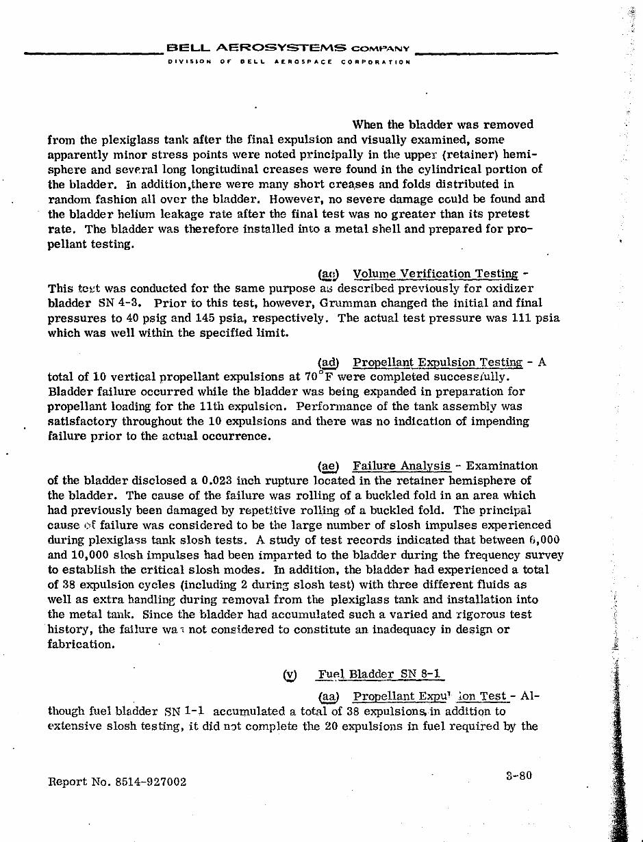
__________ BELL AEROSYSTEMS COMP,'NY _________ _
DIVISION or DELL AEROSPACE CORPORATION
When the bladder was removed from the plexiglass tank after the final expulsion and visually examined, some apparently minor stress points were noted principally in the upper (retainer) hemisphere and several long longitudinal creases were found in the cylindrical portion of the bladder. In addition,there were many short crea,ses and folds distributed in random fashion all ovcr the bladder. However, no severe damage could be found and the bladder helium leakage rate after the final test was no greater than its pretest rate. The bladder was therefore installed into a metal shell and prepared for propellant testing.
<!!~ Volume Verification Testing -This tc~t was conducted for the same purpose a~ described previously for oxidizer bladder SN 4-3. Prior to this test, however, Grumman changeci the initial and final pressures to 40 psig and 145 psia, respectively. The actual test pressure was 111 psia which was well within the specified limit.
(ad) Propellant Expulsion Testing - A total of 10 vertical propellant expulSions at 70°F were completed succesEiully. Bladder failure occurred while the bladder was being expanded in preparation for propellant loading for the 11th expulsion. Performance of the tank assembly was satisfactory throughout the 10 expulSions and there was no indication of impending failure prior to the actual occurrence.
(ae) Failure AnalysiS - Examination of the bladder disclosed a 0.023 inch rupture located in the retainer hemisphere of the bladder. The cause of the failure was rolling of a buckled fold in an area which had previously been damaged by repetitive rolling of a buckled fold. The principal cause d failure was considered to be the large number of slosh impulses experienced during plexigla,>s tank slosh tests. A study of test records indicated that between 6,000 and 10,000 slosh impulses had been imparted to the bladder during the frequency survey to establish the critical slosh modes. In addition, the bladder had experienced a total of 38 expulsion cycles (including 2 during slosh test) with three different flUids as well as extra handline; during removal from the plexiglass tank and installation into the metal tank. Since the bladder had accumulated such a varied and rigorous test (
. history, the failure wa 1 not considered to constitute an inadequacy in design or fabrication. i
_F_u~;:.1~B~1::::a:::;dd==ee.::r~S~N~8--,1=-
(aa) Propellant Expu' Lon Test - Although fuel bladder SN 1-1 accumulated a total of 38 expulsions, in addition to t'xtensive slosh testing, it did n:.>t complete the 20 expulSions in fuel required by the
Report No. 8514-927002 3-80
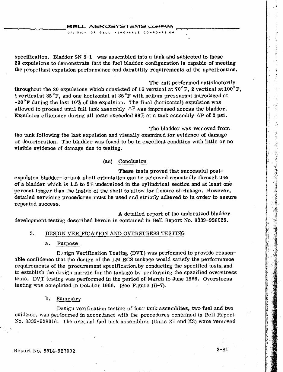
__________ BELL AEROSYST2MS COMPANY ___________ _
DiViSION OF DELL AEqOSPAC£ CORPORATION
specifim1.tion. Bladder SN 8-1 was assembled into a tank and subjected to these 20 expulsions to demonstrate that the fuel bladder configuration is capable of meeting the propellant expulsion performrulce and durability requirements of the lSI'lecification.
The \!nit performed satisfactorily throughout the 20 e}.."pulsions which consi;:;ted of 16 vertical at 70°F, 2 vertical atlOOoF, 1 vertical at 35 of, and one horizontal at 35 of with helium pressurant introduced at -20°F during the last 10% of the expulsion. The final (horizontal) expulsion was allowed to proceed until full tank assembly 6P was impressed across the bladder. Expulsion efficiency during all tests exceeded 99% at a tank assembly 6P of 2 psi.
The bladder was removed from the tank following the last expulsion and visually examined for evidence of damage or deterioration. The bladder was found to be in excellent condition with little or no visible evidence of damage due to testing.
(ac) Conclusion
These tests proved that successful postexpUlsion bladder-to-tank shell orientation can be achieved repeatedly through use of a bladder which is 1.5 to 2% underSized in the cylindrical section and at least one percent longer than the inside of the shell to allow for flexure shrinkage. However, detailed servicing procedures must be used and strictly adhered to in order to assure repeated success.
A detailed report of the undersized bladder development testing described herc:n is contained in Bell Report No. 8339-928025.
3. DESIGN VERIFICATION AND OVERSTRESS TESTING
a. Purpose
D.' "lign Verification Testing (DVT) was performed to provide reasonable confidence that the design of the LM RCS tankage would satisfy the performance requirements of the procurement specification, by conducting the specified tests, and to establish the design margin for the tankage by performing the specified overstress tests. DVT testing was performed in the period of March to June 1966. Overstress testing was completed in October 1966. (See Figure III-7).
b. Summary
DeSign veriJieation testing of four tank assemblies, two fuel and two oxidizer, was performed in accordance with the procedures contained in Bell Report No. 8339-928016. The original :!\le't talik assemblies (Units Xl and X3) were removed
Report No. 8514-927002 3-81
.; ..
:;
:~
" I'
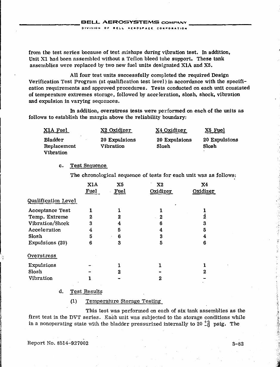
", ,
__________ BELL AEROSYSTEMS COMPANY __________ _
DIVISION 0,. 8£~L. AEIIIi(\SI'AC£ COMPOIIIATION
from the test series because of test mishaps during vLbration test. In addition, Unit Xl had been assembled without a Teflon bleed tube support. These tank assemblies were replaced by two liew fuel units designated.XIA and X5.
All four test units successfully completed the required Design Verification Test Program (at qualification test level) in accordance with the specification requirements and approved procedures. Tests conducted on each unit consisted of temperature extremes storage, followed by acceleration, slosh, shock, vibration and expulsion in varying sequences.
In addition, overstress tests were performed on each of the units as follows to establish the margin above the reliability boundary:
XIA Fuel X2 Oxidizer X4 Oxidizer X5 Fuel
Bladder 20 Expulsions 20 Expulsions 20 Expulsions Replacement Vibration Slosh Slosh Vibration
c. Test Seguence
The chronological sequence of tests for each unit was as follows:
XlA X5 X2 X4 fuel Fuel Oxidizer Oxidizer -
gualification Level
Acceptance Test 1 1 1 1 Temp. Extreme 2 2 2 2 Vibration/Shock 3 4 6 3 Acceleration 4 5 4 5 Slosh 5 6 3 4 Expulsions (20) 6 3 5 6
Overstress
E}.."})ulsions 1 1 1 Slosh 2 2 Vibration 1 2
d. Test Results
(1) Temperature Storage Testing
This test was performed on each of six tank assemblies as the first test in the DVT series. Each unit was subjer::ted to the storage conditions while in a nonoperating state with the bladder pressurized internally to 20!i3 psig. The
Report No. 8514-927002 3-82
J
., ."
__________ BELL AEROSYSTEMS COMPANY _________ _
DIVIS,ON OF BELl.. AEROSP"'C£ eORf'ORA'rION
+0 units were maintained at a temy;erature of -20 _5°F and held at this temperature for 12 hours before being conditioned to room temperature. At this point a helium bladder leakage test and a tank assembly leak test were performed. The unit was then conditioned to a temperature of 160 :8 OF and maintained at this temperature for 12 hours before being conditioned to room temperature. The helium bladder leakage test and tank assembly leakage tests were repeated at this pOint.
(a) Unit X2
This unit was the first to be tested and excessive flange leakage was evident after the initial (-20°F) storage period. An investigation disclosed that the residual torque on the flange bolts varied considerably, and the gap between the flange and shell varied 0.010 inch indicating improper assembly technique. As a result of this failure the acceptance test procedure was revised to more rigidly cont: ')1 the bolt tightening operation by including specific instructiollS for attaining the required torque values in uniform incremental ste)s. The bolts were tightened in accordance with the revised p!ocedure and Unit X2 was again subjected to the temperature storage test and successfully completed the test.
(b) Units Xl and X3
These two tank assemblies successfully completed temperature storage testing; however, both assemblies were overtested dUring subsequent testing and were replaced by Units X1A and X5.
(c) Units X1A, X4, and X5
All three test units successfully completed the temper-ature storage test.
p,(namic Testing
All four DVT test units were subjected to acceleration, slosh, vibration and shock tests. While undergoing the dynamic environments, the following liquids were used to simulate the propellants:
Oxidizer:. Freon-'I':iY mixed with 3 ~~% methyl alcohol by volume.
Fuel: Distilled water inhibited with 0.1% chromic acid by weight.
The units were pres:>urized to 250 psig with nitrogen for all dynamic testing except Launch/Boost vibration which was accomplished at a pressure of 40 ·psig.
Heport No. 8514-927002 3-83
I . ! .'i: i ;
I I· I
I i ,
i i I I I I t , . : j .
•
_____ ____ BELL AEROSYSTEMS COMPANY __________ _
DIVISION OF' BELL AEROSPACE CORPORATION
(a) Slosh
The tank assemblies were mounted directly to the test fixture (hard mounted) for slosh testing and were installed on the slosh machine in the vertical flange-down attitude. The units were loaded to 1/3-specification volume and were subjected to 500 :tlosh impulses along the Y-axis at the following input . levels:
~ Oxidizer Fuel
Freguency
3.2 cps 3.0 cps
Input Displacement
0.19 inch DA 0.22 inch DA
All four test units successfully completed the DVT slosh testing.
Upon completion of the DVT test series, overstress slosh testing was performed on Fuel Unit X5 and Oxidizer Unit X4. The overstress conditions were as follows:
1.33 Qualification Level 300 cycles Oxidizer X4: 3.2 cps at .25 inch DA Fuel X5: 3.0 cps at .29 inch DA
1.67 Qualification Level 100 cycles Oxidizer X4: 3.2 cps at .32 inch DA Fuel X5: 3.0 cps at .37 inch DA
2.0 Qualification Level 50 cycles Oxidizer X4: 3.2 cps at .38 inch DA Fuel X5: 3.0 cps at .44 inch DA
Both tank assemblies successfully completed overstress slosh tests.
It should be noted that at the completion of each slosh test the liqUid was forced from the tank by collapsing the bladder, thus constituting an added expUlsion cycle on the blarlder.
(b) Acceleration
Each unit was mounted on Grumman support brackets, loaded to specification volume, and mounted on. the centrifuge with the -'-X-axis horizontal and extending radially outward from the center of rotation. An acceleration force of 8.5 g was applied for 5 minutes. The unit was then turned so that the -X-axis extended radially outward from the cen.ter of rotation and the 8.5 g acceleration force was applied for 5 minutes. All four test units successfully completed acceleration testing with no indication of damage.
Report No. 8514-927002 3-84
I I
i !
, , "-~ ~ . ~'
__________ BELL AEROSYSTEMS COMPANY _________ _
DIVISION OJ' DELL. AEROSPACE CORPORATION
(c) Vibration and Shock
(i) Test Conditions
All four tank assemblies were installed on the Grumman support brackets and mounted i1,1 the vertical flange-down attitude for vibration and shock testing. The testing included launch and boost level vibration, IWlar descent level vibration (and shock), and lunar ascent level vibration. Each level was performed in all three mutually perpendicu.lar axes. Each unit was tested at all required levels in one axis and then was drained and leak tested prior to starting the next axis .. The sequence of events for each axis was as follows:
• The unit was loaded to specification cc).pacity and pressurized to 40 psig for launch/boost vibration. Upon completion of this vibration level, the pressure was reduced to 5 psig and sufficient liquid was drained to leave 75% of specification volume loaded in the tank. The tank was then pressurized to 250 psig and vibrated in accordance with the descent level requirements. With the 75% load and 250 psig pressure in tank, the assembly was given three 15 g shock pulses first in the plUS, then in the minus direction along the axis of vibration. Pressure was vented to 5 ±.5 psig and the unit was visually inspected.
• Following the shock test, sufficient liquid was drained to leave 50% of specification volume in the unit. The tank was pressurized to 250 psig and vibrated in accordance with the lunar ascent reqUirements. The liquid was then expelled by collapsing the bladder and the tank and brackets were visually examined for evidence of damage. A helium leakage test was conducted to evaluate internal bladder assembly damage. It should be noted that the expulsion of liquid after each axis of vibration constituted an additional 3-expulsion cycles for each tank during vibration test.
• After completion of all three axes of vibration and shock tesl ,ngj each unit was subjected to a tank assembly leakage test and then was ~-rayed for possible structural damage.
Overstress vibration on the X1A fuel and X2 oxidizer units was performe(l with inputs at 1.33,1.67, and 2.0 times qualification lev<:lls while loaded to speCification volume. The tank assem1::ly was drained and a helium leakage test was l';:mtiuded afb~r test in each axis.
Report No. 8514-927002 3-85
, . ,
__________ BELL AEROSYSTE""S COMP,",NY __________ _
DIVISION Or: BEL.\.. A.EAOSPACE CORPORATION
(ii) TfJSt Results
All four units successfully completed qualification level vibration and shock testing. It was planned to replace the bladders on XIA fuel and X2 oxidb:er units prior to overstress vibration. The planned replacement was accomplished on XIA,and the unit satisfactorily withstood the entire overstress vibration sequence with no evidence of damage to the test unit or the vehicle mounting brackets.
The planned bladder replacement was not accomplished on X2, prior to overstress vibration,ill order to determine the ultimate life of the bladder. During overstress vibration, bladder failute was indicated after Y-axis testing at the 1.33 level. This bladder had previously Withstood all qualification level tests, overstress expulSion tests and Z-axis overstress vibration tests at the 1.33 level. Testing was continued and the tank shell ruptured during the last scheduled axis of overstress vibration test. Failure occurred near the end of the X-axis sinusoidal sweep at 2.0 times qualification level.
(3) Expulsion Cycle Test~ng
(a) Test Conditions
All four test units successfully completed the series of expulSions specified in Table III-I. Nitrogen tetroxide was used in the oxidizer units and hydrazine/UDMH blend in the fuel units. The tests were conducted in accordance with the specified conditions of temperature, flow rate, flow duration, and shutdown b.P. The testing series demonstrated the capability of the tank assembly to meet the follOWing performance requirements:
• Cycle Life - Twenty propellant expulsion cycles comprised of 16 at ambient temperature (65 ° to 75°F), 2 at lfrgh (100° to 105°F), and 2 at low temperature (35° to 40°F).
• Pulsed Flow - Ability to expel propellant in flow bursts of various durations. This was performed on the eighth, ambient, flange-down expulsion.
• Expulsion Efficiency Vertical - Demonstrate an expulsion efficiency of 95% at a .6 P'" 2.5 psi at all flow and temperature conditions specified with the tank in a ve:L'tical attitude.
• Expulsion Efficiency Horizontal - Demonstrate the ability to expel a minimum of 87% of capacity in the horizontal attitude. This was demonstrated
Report No. 8514-927002 3-86
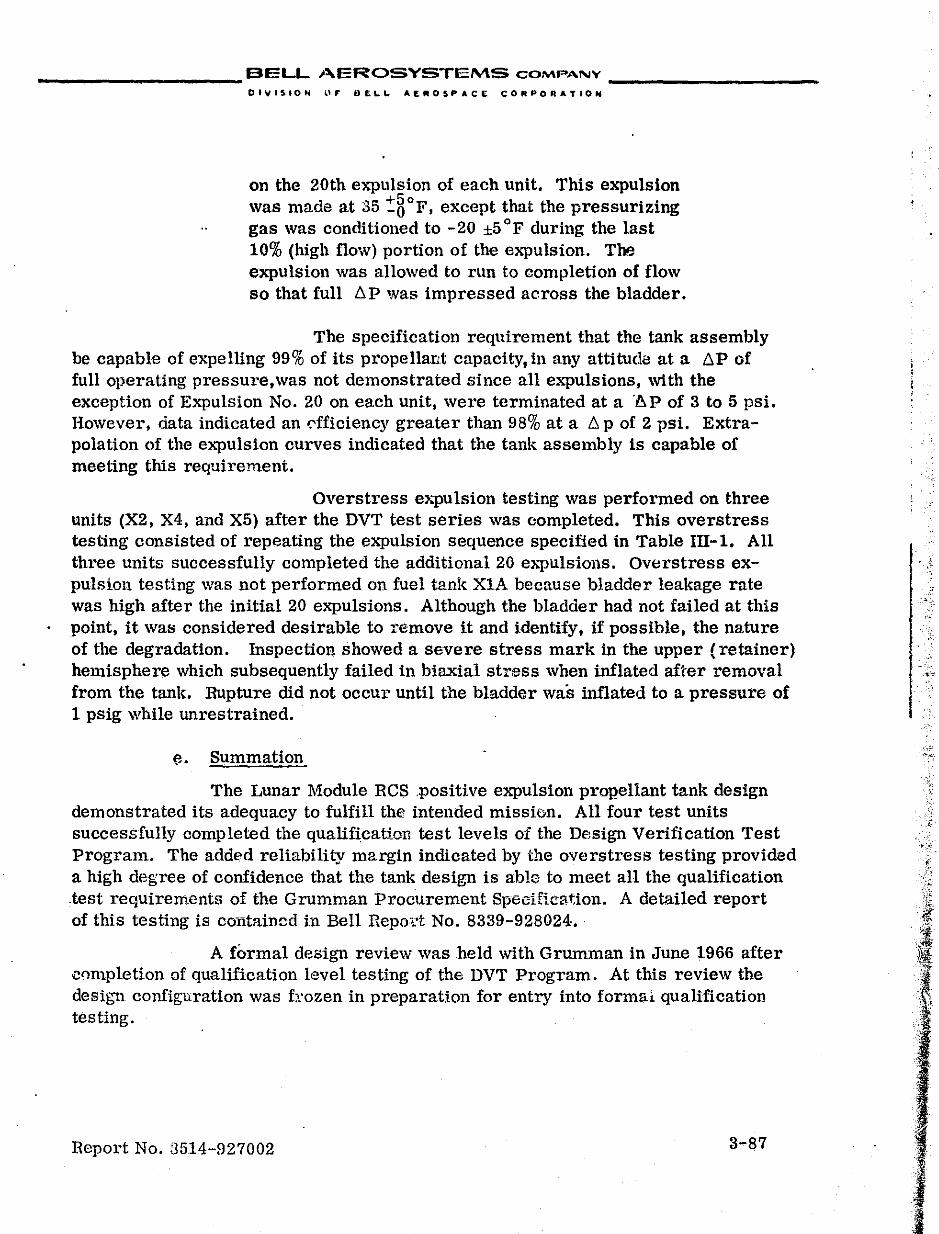
__________ BELL AEROSYSTEMS COMPA-NY __________ _
DlVISION 1.." DELL AE. .. 05PACE COfitPORATIOH
on the 20th expulsion of each unit. This expulsion was made at 35 :soF, except that the pressurizing gas was conditioned to -20 ±5 of during the last 10% (high flow) portion of the expulsion. The expulsion was allowed to run to completion of flow so that full LlP was impressed across the bladder.
The specification requirement that the tank assembly be capable of expelling 99% of its propellant capacity, in any attitude at a LlP of full operating pressure,was not demonstrated since all expulsions, with the exception of Expulsion No. 20 on each unit, were terminated at a l~.P of 3 to 5 psi. However, data indicated an dficiency greater than 98% at a Ll p of 2 psi. Extrapolation of the expulsion curves indicated that the tank assembly is capable of meeting this requirement.
Overstress e>"llulsion testing was performed on three units (X2, X4, and X5) after the DVT test series was completed. This overstress testing consisted of repeating the expulsion sequence specified in Table IIl-1. All three units successfully completed the additional 20 eAllulsions. Overstress expulsion testing was not performed on fuel tank XIA because bladder leakage rate was high after the initial 20 expulsions. Although the bladder had not failed at this point, it was considered desirable to remove it and identify, if possible, the nature of the degradation. Inspection showed a severe stress mark in the upper (retainer) hemisphere which subsequently failed in biaxial stress when inflated after removal from the tank. Rupture did not occur until the bladder was inflated to a pressure of 1 psig while unrestrained.
e. Summation
The Lunar Module ReS ,positive expulsion prop'el1ant ta.nk design demonstrated its adequacy to fulfill the intended mission. All four test units successfully completed the qualification test levels of the Design Verification Test Program. The addl"d reliability margin indicated by the overstress testing provided a high degree of confidence that the tank design is able to meet all the qualification test reqUirements of the Grumman Procurement Specification. A detailed report of this testing is cOTItained in Bell Repod No. 8339-928024 •.
A formal design review was held with Grumman in June 1966 after i!l)mpletion of qualification level testing of the DVT Program. At this review the design configuration was f):ozen in preparation for entry into formal. qualification testing.
Report No. 3514-927002 3-87
I-, '; -
, ..
;
I
;~
\~ .• ~. .~
·.1
).·.[t·.I·"'·····.
..
'. ,} -, ,

__________ BELL AEROSYSTEMS COMPJ\",Y _________ _
Olyl510H OF DELL .£"OS~ACE CO"~O".TION
TABLE ill-1 EXPULSION TEST SEQUENCE
Test Flange Orientation Tem[!erature tF)
Leakage - Helium Down 70 ±5
*Expulsion No. 1 Down 70 ±5 thru 8
Leakage - Helium Down '10 ±5 Expulsion No. 9 Up 70 ±5
thru 16
Leakage - Helium Down 70 ±5 Expulsion No. 17 Down 1001:8
Leakage - Helium Down 70 ±5 Expulsion No. 18 Up loots Leakage - Helium Down 70 ±5 ExpulSion No. 19 Down 35 '!:8 Leakage - Helium Down 70 ±5 **Expulsion No. 20 Horizontal 35 t8 Leakage - Helium Down 70 ±5
* Elq)ulsion No. 8 pulsed.
** Expulsion No, 20 performed so that during the last 10% of the expulsion (highflow portion) the pressurizing gas was at a temperature of -20 ±5 of and the expulsion proceeded to full tank LlP.
NOTE
The low medium, and high flow rate ea:pability was demonstrated on Expulsions No.1, 9,17,18,19, and 20 as follows:
. Low flow rate to 60% expulsion Medium flow rate 30% expulsion High flow rate 10% expulsion
All other expulsions were performed at the high flow rate only.
Report No. 8514-927002 3-88
•
-.'-<
I
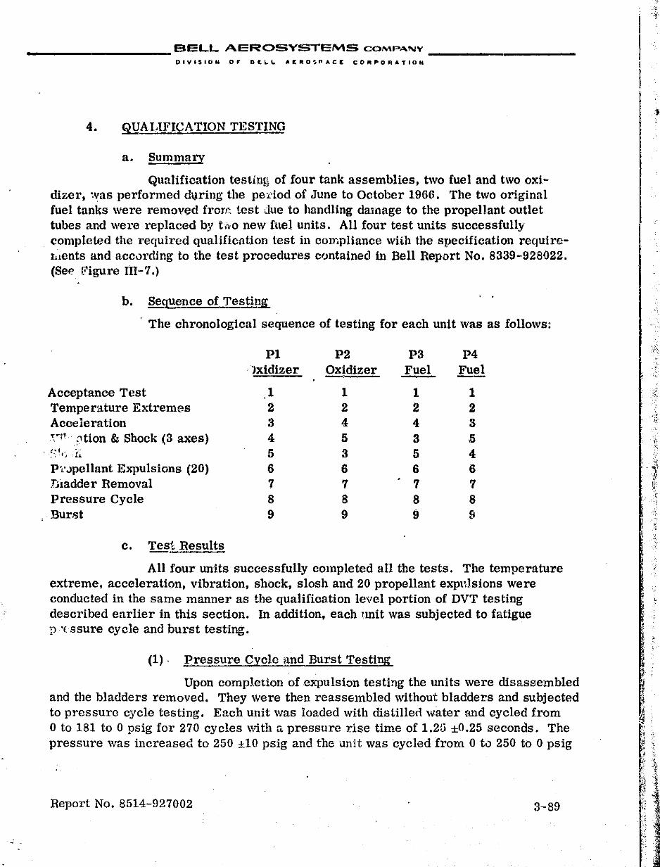
.:
__________ BELL AEROSYSTEMS COM!"."'''- __________ _
DIVI$ION 0,. D£LI. AERO~PACE CORPORATION
4. QUALIFICATION TESTING
a. Summary
Qualification testing of four tank assemblies, two fuel and two oxi.dizer, ~vas performcd during the pe:dod of June to October 1966. The two original fuel tanks were removed from test due to handling damage to the propellant outlet tubes and were replaced by tto'O new fuel units. All four test units successfully completed the required qualification test in compliance wUh the specification requirclllents and accurding to the test procedures contained in Bell Report No. 8339-928022. (Se" [i'igure m -7.)
b. Sequence of Testing
. The chronological sequence of testing for each unit was as follows;
PI P2 P3 P4 )xidizer Oxidizer Fuel Fuel
Acceptance Test 1 1 1 1 Temperature Extremes 2 2 2 2 Acceleration 3 4 4 3 ":'1'~1tion & Shock (3 axes) 4 5 3 .5
. :~'I·~- !~ 5 3 5 4 P'L'.)pellant ExpulSions (20) 6 6 6 6 niadder Removal 7 7 7 7 Pressure Cycle 8 8 8 8 Burst 9 9 9 &
c. Test Results
All four units successfully completed all the tests. The temperature extreme, acceleration, vibration, ShbCk, slosh and 20 propellant expl1]sions were conducted in the same manner as the qualification level portion of DVT testing described earlier in this section. In addition, each lmit was subjected to fatigue 1).'( ssure cycle and burst testing.
(1), Pressure Cycle ilnd Burst Testing
Upon completion of expulsion testing the units were disassembled and the bladders removed. They were then reaSSEmbled without bladders and subjected to pressure cycle testing. Each unit was loaded with distillerl water and cycled from o to 181 to 0 psig for 270 cycles with n. pressure rise time of 1.2ti ±O.25 seconds. The pressure was increased to 250 ".10 psig and the unit was cycled from 0 to 250 to 0 psig
Report No. 8514-927002 3-89
I ,~
I I
'/
11 I' ,I " \'
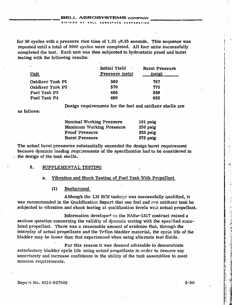
BELL AEROSYSTEMS COMPANY __________ _
DiViSION 0' OE&..L. AEROSPACE COIIIPORATION
for 30 cycles with a pressure rise time of 1.25 ±0.25 seconds. This sequence was repeated until a total of 3000 cycles were completed. All four units successfully completed the test. Each unit was then subjected to hydrostatic proof and burst testing with the following results:
Initial Yield Burst Pressure Unit Pressure (psigl (psigl
Oxidizer Tank P1 560 767 Oxidizer Tank P2 570 775 Fuel Tank P3 460 589 Fuel Tank P4 490 622
Design requirements for the fuel and oxidizer shells are as follows:
Nominal Working Pressure Maximum Working Pressure Proof Pressure Burst Pressure
181 psig 250 psig 333 psig 375 psig
The actual burst pressures substantially exceeded the design burst requirement because dynamic loading requIrements of the specification had to be considered in the design of the tank shells.
5. SUPPLEMENTAL TESTING
a. Vib~ation and Shock Testing of Fuel Tank With Propellant
(1) Background
Although the LM RCS tank!lrrc wa.s successfully qualified, it VIas recommended in the Qualification Report that one fuel and ol?e oxidizer tank be subjected to vibration and shock testing at qualification levels with actual propellant.
Information developer! on the NASw-1317 contract raised a serious question concerning the validity of dynamic testing with the specified simulated propellant. There was a reasonable amount of evidence that, through the interplay of actual propellants and the Teflon bladder material, the cycle life of the bladder may be lower than that experiencHd when using alternate test fluids.
For this reason it was deemed advisable to demonstrate satisfactory bladder cycle life using actual propellants in order to rell'lOVe any uncertainty and increase confidence in the ability of the tank assemblies to meet mission reqUirements.
Repo-:-t No. 8514-927002 3-90
, I
I I . I
--.j'--
I -~i l~ ·1"-
.;r~ , ::J 'i: , -'"~
c -w ffi
" j,~ ., ,~
~ .. ~
, ,~ " \.I • '; -Ii' , ~I '-4
,~ " " ,~ 'i .if , t; -~ ., "
" T' • .1 '".!
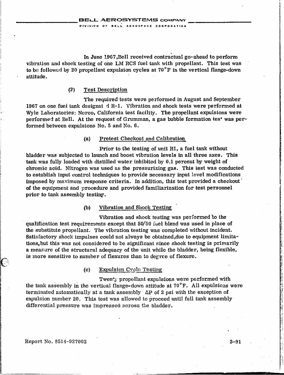
_________ ,_BELL ,n.EROSYST'EMS COMPANY _________ _
DfVI$iO .. O~ BELL AEROSPACE CORPORATION
. In June 1967 ,Bell received contractual go-ahead to perform
vibration and shock testIng of one LM RCS fuel tank with propellant. This test was to bn followed by 20 propellant expulsion cycles at 70°F in the vertical flange-down attitude.
(2) Test Description
The required tests were performed in August and September 1967 on one fuel tank designat ::I R-l, Vibration and shock tests were performed at
r Wyle Laboratories; Norco, California test facility. The propellant expulsions were performed at Bell. At the request of Grumman, a gas bubble formation tes~ was performed between expulSions No.5 and No.6.
~ . . .. :;
(a) Pretest Checkout and Calibration
Prior to the testing of unit Rl, a fuel tank without bladder was subjected to launch and boost vibration levels in all three axes. This tank was fully loaded with distilled water inhibited by 0.1 percent by weight of chromic acid. Nitrogen was used as the pressurizing gas. This test was conducted to establish input control techniques to provide necessary input level modifications imposed by maximum response criteria. In addition, this test provided a checkout' of the equipment and procedure and provided familiarization for test personnel prior to tank assembly testing'.
(b) Vibration and Shock Testing
Vibration and shock testing was performed 'to the qualification test requirements except that 50/50 iuel blend was used in place of the substitute propellant. The vibration testing was completed without incident. Satisfactory shock impulses could not always be obtained,due to equipment limitations, but this was not considered to be significant Rince shock testing is primarily a mear-ure of the structural adequacy of the unit while the bladder, being flexible, is more sensitive to number of flexures than to degree of flexure.
(c) Expulsion Cveln Testing
Twen':j- propellant expulsions were performed with the tank assembly in the vertical flange-down attitude at 70 of. All expulsions were terminated automatically at a tank assembly liP of 2 psi with the exception of expulsion number 20. This test was allowed to proceed until full tank assembly differential pressure was impressed 3cross the bladder.
Report No. 8514-927002 3-91
1 "
, ~,
.'i
---------
__________ BELL AEROSYSTEMS COMPANY __________ _
DIVISION OF DELI.. AEROSPACE. CORPORATION
(d) Gas Bubble Formation Test
Following expulsion No.5 and the subsequent bladder leakage test, Grumman requested that the tank assembly be loaded to specification volume and stored with a 40 psig helium pad at room temperature to determine the extent, if any, ot' gas bubble formation on the liquid side of the bladder. This request was complied ,"vithin the following wanner:
!/ The tank assembly was loaaed, ullage was drained, and 42 psig helium trapped on the gas side of the bladder.
2/ After approximately 84 hours, the trapped pressure had decreased to 25 psig. The pressure was increased again to 40 psig and the upper portion of the tank assembly was X-rayed to determind bladder position and t6 detect the presence of a liquid-gas interface.
Y The top of the bladder was then vented through the bleed port and into a gas sampler, while maintaining 40 psig on the gas side of the bladder.
11 The upper portion of the tank assembly was then X-rayed to detect any change in bladder position as a result of the rebleeding.
W The sample obtained in step 3/ was analyzed for helium content.
The results of this test were as follows:
!I A study of the X-ray made prior to rebleeding disclosed no visible gas entrapment at the top of the bladder. The X-ray made after rebleeding showed no visible change in bladder position or folds when compared to the original X-ray, thus indicating that no discernible gas bubble existed within the bladder.
y A 20 cc gas bubble was collected in the sampler at a sample pressure of 3 8.5 psig. Spectrophotometric analysis disclosed that 5.9 cc of this bubble was helium. The remaining 14.1 cc was probably propellant vapors trapped at the top of the bladder during the tank assembly loading operation, since post-load ullage was drained from the outlet tube at the bottom of the tank rather than from the bleed tube at the top of the tank.
These results led to the conclusion that prelaunch bubble formation within the bladder is essentially negligible in the case of the LM ReS fuel tank,since the 5.9 cc bubble would be compressed to approximately 1.66 cc at a nominal tank working pressure of 181 psig. Since the bubble formation test was merely an extension of the primary test pl'bgram, the follOWing variables existed which could not be fully controlled or quantatively evaluated -Cor ~heir effects on bubble size:
Report No. 8514-927002 3-92
,
__________ E!.ELL AEROSYSTEMS COMPA.NY _________ _
OIVISION 0,. Of::LL AEROSPACE CORPOrtATtON
}j Some of the 5.9 cc of helium in the sampler was in solution in the fuel and wel.'t out of solution when the fuel,at 40 psig in the tank i
was bled into the sampler. Solubility data of helium in SO/50 fuel blend indicates that the entire 5.9 cc could have come out of solution with the 1.5 psi drop in pressnre which occurred when the tank was bled.
2/ Some of the 5.9 cc of helium may have been part of the trapped gas at the top of the tank after loading, since ullage was not drained from the bleed tube at the top, but from the outlet tube at the bottom. (Helium is used to supply back-pressure to keep the bladder expanded during loading.)
Y The pressure drop from 40 psig to 25 psig,that occurred during the test,cannot be attributed entirely to helium permeating the bladder and dissolving in the fuel. Based on the solubility of heliUJ , in 50/50 fuel, the pressure should have dropped only to 34.9 psig. It would appear that the remaining decrease of 10 psi was probably due to minor leakage in the test system.
11 Although the bladder had been purged and subjected to a helium leak check prior to loading for this test, it had been exposed to fuel for three days prior to this test and traces of fuel may have been still present within the bladder membrane. It is P05:Hble that gas permeation rate subsequen.t to the initial loading of a dry bladder may be different.
Since the size of the helium bubble proved to be comparatively innocuous during this test, it seems apparent that if any or all of the above variables were applied, the result would still be effectively negligible.
(3) ConclUSions and Recommendations
The LM ReS fuel tank assembly successfully completed vibration and expulsion testing with actual propellant with no significant degradation of the bladder.
I The results of this t~st program yielded a high level of confidence in the capability OJf the fuel tank assembly to successfully meet the Apollo mission requirements.
Although there appears to be no significant prelaunch gas bubble problem in the fuel tank, it was recommended that the following conditions be met during prelaunch servicing for both fuel and oxidizer tanks:
1/ Post-load ullage be drained from the bleed tube.
2/ A rebleed thTough the bleed tube be made, if pOSSible, within 24 hours of launcl1 or at least 24 hours after loading.
Report No. 8514-927002 3-9~
•
__________ BELL AEROSYSTEMS COMPANY ___ , ______ _
M'
DIVISION OF SELL AERO$PACE CORPORATION
3/ The tank be pressurized to working pressure as soon as feasible after rebleeding.
A detailed report of this testing is contained in Bell Report No. 8339-928027.
6. FINAL DESIGN CDNFIGtffiATION
The final design configuration which was qualified and delivered as flight hardware is shown in Figure 11-4 and may be generally described as follows:
Titanium tank shell - not peened (except for 3 oxidizer and 3 fuel tanks with peened shells which were delivered to Grumman as flightworthy hardware).
Diffuser assembly of the same materials as Apollo RCS diffusers. Diffuser and outlet tube 3/4 inch D.D. and bleed tube 3/l6-inch D.D.
Undersized bladder with no buffer pad at the ret'dnel" end.
Shipping closure with provisions for expanding the underSized bladder during shipping and relaxing the bladde r during storage.
Deliverable tank configuration has no helium inlet port fitting, A shipping closure fitting is substUllted.
Report No. 8514-927002 3-94
i I 1 I ,
-f
j -"<
i i _ , -. -'i I
i , . • I I
1 1-
__________ BELL AEROSYSTEMS COMPANY _________ _
DIVISION OF BELL AEAOSP .. CE CORPORATION
C. MODEL 8400 S~TURN SIVB TANKAGE PROGRAM
1. DESIGN
In December 1964,Bell received contractual go-ahead to supply positive expulsion tankage for the Saturn SIVB Auxiliary Propulsion System. Each system includes two fuel tanks for use with MMH,and two oxidizer tanks for use with N204' The fuel and oxidizer tanks are the same size and were based originally on the Lunar Module oxidizer tank configuration except that the SrvB design cC':!ltained an additional gas pressurization port at the blind end of the tank for greater ease in purging and servicing the gas side of the bladder. Since this tallk is always operated in the vertical flange-down position, this port became the primary pressurization point. The resulting program is shown in Figure Ill-S. Shortly after initiation of design effort Bell was directed to incorporate the following additional changes:
• Higher burst pressure (550 psig)
• All stainless steel (347) diffuser assembly
• Tube fitting:> and MC fla:ces on propellant outlet and bleed tubes
Preliminary release of the final design configuration was made in March 1965 with formal release follOWing in April. During this period the Lunar Module tank program started plexiglass tank testing and experienced a bladder failure due to bladder-to-tank shell friction during post-expulsion repositioning of the bladder. Since the SIVB tank design utilized the then current LM olCidizer full size Single-ply bladder, a temporary hold was imposed on bladder fabrication for the SrvB program pending resolution of the problem. Meanwhile, limited development testing was inihated with a plexiglass tank to evaluate the effect of va.rious pu:::ge and servicing procedures on bladder behavior. During these tests it was found that post-expulsion repositioning of a full-size bladder is possible by pressurizing both the inside and outside of the bladder to an equal value and control-venting the blind-end gas port to create a low pressure area at the top of the tank. Consequently, twelve tank assemblies were assembled with full-size bladders and delivered to Douglas as an interim configuration for testing purposes.
In the summer of 1965 an undersized bladder configuration proved successful'in overcoming the LM repositioning problem and was incorporated into the LM tank design. In the fall of 1965 the srvB tank design was altered to incorporate the undersized bladder. In conjunction with the incorporation of the undersized bladdcl', a shipping closure similar to that of LM was designed with a common line and a hand valve bctween the liquid and gas sides of the bladder. Since Douglas had need for such a device on the tanks after assembly into the propulsion system,
Report No. 8514-927002 3-95
.;. ,
.'
, , , . ,
.,' , .' .'
, ,
, I; , . •.
" ., ','"" -:. ,.
~;
~. ~ ~~, ,~. , . i~'
" /.
"
.
.
.~~~~"·.""""'<_'~'U'''· ....... ,'t ..... ___ , ~,:...b' ... "' ..... _ ... '""~''"i ... " ...... V'_.., ... ~. "' ..... 11i.,' · .. ;· .......... n'''-L'''''' ... +'' ..... fl''''' ... t. .. ~,~ ... _ ..... ~''''L. d ........ ~"t~ ............ " ___ ........... __ ~.~' __ ~_~,,~ .. w" ____ • '_~ ___ ""._"""';"'-':; " _._._
FIGURE TIl-8 MODEL 8400 SATURN SIvn "
1964 1965 , I DEC JAN I fEB I MAR I APR I MAY I JUN I JUL I AUG I SEP I OCT I NO,' I CEC
'ROGRAM OO-AHEaD IV DESIGN \J \l UNDERSIZED 1
;:. -, DESIOII DAC BLADDlR :
COMPLETE APPHOVAL INCORP. ~-
(' "
T£STlNG
I . BLADDER/PL£KIGLASS I _,J t. SltElt !lElO QUIL 0
C. OEV£lO'~EHT
n OKIOIZ£R
Xl FUE.I.
XlA fUEL
K4 FUEL
, C:'JAlIFICATIDIl
PI FUEL
PZ OKIOIZER
-
Repod No. 8514-927002
________ . ___ BELL AEROSYSTEI'v\S COM' "'''IV ________ -, _
DIYISION 0' 8£1..1.. At;.RO!.J1ACE CO,.pO ...... TIOH
: URN SIVB PROGRAM HISTORY
" --""
19bb "b7
I DEC JAN I FEB \ MAR I APR I MAY I JUN 1 JUl I AUt; I 5[P - I DCI I "'O'w I DEC JAN
~ PEENEU Y OXIO SHELL
(
, ,
" : , ~~
.'
,
. ;.~ t;
,",",
f. [l] V&5 V [ t r
m , 5 ~ , , [ n H ... ~ I XYZ Z 711 I ";-,
- ~~:-:
~Dj P
~I::J l: E '4.' , ':
" :~~ ~-;
0 P E P E '(: E A E A \,,'" 5 I I ~ ..
", ~~. ;,
!t,
~ ".
~ 'f: E • ~. 'II. S , !' •
. '"';:i: y .'j-' ~
" '-"
• '::<-.. f" "- "-":
~ BW [I'~ .;i~ , .- r & A~~ic. , ¢:-, 5 1 7 i I 'h 1
HZ
~ ~ [ Ell
E & ; 1~i S
x L
"~;., ':, • , ,
.~' •• ';>
.:;' jlD;I,d)OUT FRAU ~
.. ,':: 3-96
;,"~
; '~:~: ,·':.~1 -" _ "'_"_-=~ __ .',",~. __ • _ .. •
__________ BELL AEROSys".EMS COMPANY __________ _
D"iI~.OH 0" 1!d"~ L At;"OSPACIt COtlPO"ATIOH
the closure installation envelope was redesign(;;d tt' make it compatible with the SIVB installation. All SIVB APS tanks are now installed and serviced with closure assemblies installed.
During the Apol!o stress corrosion investigation it was found that internal peening of titanium tank shells would retard stress corrosion caused by red N20 4• Since the specified oxidizer for the SIVB tankage at that time was red N204' eleven tank shells were internally glass-bead peened at the NASA Langley Research C~nter in February 1966. Three of the eleven peened shells were retained at Langley for testing, two were assigned for use on the development program at Bell, and the remainir.g, six were assembled into oxidizer ta'1k assemblies and delivered to Douglas. The subsequent adoption of N20 4 with a controlled NO content as an effective stress corrosion inhibiting measure precluded further use of peened oxidizer tank shells on the SIVB program until the summer of 1967. At this time Bell was directed to deliver all tank assemblies, both oxidizer and fuel, with internally peened shells. Tank shell and assembly drawings were changed to incorporate this reqUirement. Therefore, after fabrication at Bell, all SlVB tank shells are peened at Douglas then returned to Bell for assembly into tanks. Tanks which had been delivered were returned to Bell for disassembly and the shells returned to Douglas for peening. The shells were then returned to Bell for bladder replacement, reassembly, and acceptance testing.
In order to obtain more beneficial er.lissivUy effects, the final design configuration also included a poli.shed flange and polished.tubing on both the propellant outlet. port and the bleed port. These modifications were incorporated in March 1966. The final design configuration now in current delivery is the same as that of the LM oxidizer tank with the following exceptions:
2.
• Thicker tank shell - glass bead peened on inner flurface • Stainless steel diffuser a!?sembly • Top gas port for serVicing and pressurizing the bladder • Polished diffuser flange and external tubing • Shipping closure designed for storage and servicing on
the APS Module • "MC" flares on tube assemblies
TESTING
a. ·Development Testing
Development testing was limited to demo:nstration of compliance with reqUirements peculiar to the Saturn !VB APS program; therefore, reqUirements identical to those of the LM RCS tanks were not demonstrated. Additional objectives
Report No. 8514-927002 3-97
:r H· mm
~-,. -.
__________ BELL AEROSYSTEMS COMPANY __________ _
DIVISION 0,. OFLL AEROSPACE COIiltPORATION
of development testing were to assist in establishing optimum GSE servicing procedures for Douglas,and to check out and refine test procedures and eqUipment prior to initiation of formal qualification testing. The devclopment test program described in the succeeding paragraph was conducted in two phases. The first phasE:, which took place in August and September 1965, consisted of plexiglass tank testing to visually study bladder behavior. The second phase, tank assembly testing, was initiated in May 1966 and completed in November 1966.
(1) Plexiglass Tank Testing
The purpose of these tests wat> to establish and evaluate tank-to-bladder relationships by visual observation of bladder behavior under various conditions of liquid and gas flow. The specific test objectives were as follows:
• To study bladder behavior during liquid expulsion and gas re-expansion in the flange-down attitude while using the top (blind end) gas port for pressurizing and venting. Since none of the other tanks of the common teclmology "family" are equipped with this port, there was no prior test experience with this configuration.
• To evaluateservi.cing procedures for loading and bladder positioning.
• To study gas flow characteristics around the bladder and evaluate purge procedures for elimination of permeated liquids from the gas side of the bladder •.
Since this phase of testing was begun before the undersized bladder design became established on the LM program, a full size bladder was used. A total of thirty-one plexiglass tank e,.,:pulsions were made with the tank oriented in the vertical, flange-down attitude using FreoIl-TF as the expulsion medium. A detailed report of these tests is contained in Bell Report No. 8400-928015. The prinCipal findings were as follows:
• Use of the additional gas port at the blind (top) end of the tank did not meas1,1rably ?.ffect bladder behavior, tank assembly L'.P, or expulsion efficiency during' liqUid expulsion. The only noticeable difference during expulsion testing was the absence of bladder "flutter" observed during LM tank expulsions in this attitude, due to passage of pressurant gas between the bladder
Report No. 8514-927002 3-98
•
..
__________ BELL AEROSYSTEMS COMPA-NY _________ _
OIVUION 0, DE,",,, .,"OS,. ... CE CO'lPOIllATtON
and tank shell. Expulsion efficiency during these tests varied fr()m 98.2 to 98.9% at a tank assembly differential pressure of 2 psi,whlCh complied with the speCification requirement of 97.5%.
• A successful method of repositioning a full-size bladder in a tank mounted in the vertical, flangedown attitud\? was attained by utilizing the additional blind end gas port as follows:
1/ With the bladder In 8. collapsed condition, apply nitrogen gas at 25 psig regulated pressure,simultaneouslY,to the bottom gas port and propellant outlet port.
2/ Allow the bladder to expand by controlled venting through the top gas port, m,intaining a maximum differential pressure of 3 psi bstween the inlet gas pressure and the pressure at the top gus port.
• Elimination of liquids from the gas side of the bladder, by purging,did not prove to be practical within reasonable purge times and at pressures, temperatures and gas flow rates which would not be detrimental to the bladder. This Is especially true of propellants with relatively low vapor pressure, such as MMH.
• After completion of 31 expulsions the bladder was completely functional and showed no measure able indicatifJ~ of degradation. ' \
(2) Tank Assembly Testing
(3.) Summary
Tank assembly testing was initiated in May 1966. Three tank assemblies, two oxidizer and one fuel, were scheduled for dry cycles, propellant exposurtl, dynamic testing, life cycles with propellant, and shell.cycle and burst test. However, testing was cancelled on the second oxidizer tm.lk.
Report No. 8514-927002 3-99
, '
..
__________ BELL AEROSYSTEMS COMPANY ________ _
s ;;
(i) Oxidizer Tank Xl
The tank successfully completed five dry cycles, 22 day~' propellant exposure, vibration and shock at specification level, vibration at reduced level, 19 expulsion cycles, and shell <,ycle and burst tests. Bladder failure occurred after propellant expulsion cycle 19.
(Ii) Fuel Tank X3
The tank successfully completed 10 dry cycles, 33 days propellant exposure, and vibration and shock at specification level in the X and Y-axes. Excessive bladder leakage was indicated after <fibration and shock in the Y-axis. The bladder was replaced and the tank (redeSignated as X3A) was again put into test.
(iii) Fuel Tank X3A
The tank successfully completed five dry cycles, 25 days propellant exposure, and two expUlsion cycles. Testing was suspended at this point by direction of Douglas.
Under the NASw-1317 program, an additional develoyment unit, fuel tank X4, waf.' assembled and tested in accordance with the qualification test requirements which included vibration with actual propellants. This tank was subjected to five dry bladder cycles, three-day propellant exposure and vibration and shock testing with actual propellant. After vibration and shock testing in t\'10 axes (X and Y) excessive bladder leakage occurred, indicating bladder failure.
(b) Test Results
(1) Dry Cycle Testing
Prior to any tests with propellants, a series of dry cycles was perforUlE'.~ on each tank assembly. Prior to each dry expulsion the bladder was pOSitioned in accordance with Douglas GSE procedures. Bladder leak checks were performed prior to the first dry cycle and after every five cycles.
(it) Propellant Exposure Testing
(aa) Oxidizer Tank Xl
This unit was scheduled for minimum mission requirements; therefore, the propellant exposure time for this unit was to be 10 days at varying temperature and pressure conditions. However, to reduce the
Report No. 8514-927002 3-100
•
, .
__________ BELL AEROSYSTEMS COMPANY _________ _
time interval between completion of propellant exposure and initiation of dynamic testing, the propellant exposure time was extended to 22 days. At the completion of the 22-day propellant exposure, the temperature was reduced to ambient and an f.>xpulsion test was successfully completed.
(ab) Fuel Tank X3
The unit was originally scheduled for 30 days propellant exposure under varying temperature and pressure conditions. The time was extended to 34 days .. .., e;ahl supplemental information on gas formation on the liquid side of the bladder which occurred in a Model 8400 tank during checkout of an APS system at Douglas Aircraft. As part of the study, Douglas requested that fuel tank X3 be X-rayed for evidence of gas inside the bladder. The initial X-ray of tank X3 was taken after 27 days of exposure and after temperature and pressure cycling, and showed gas formation above the liquid inside the bladder. The gas was vented and, when analyzed, revealed 400 parts helium to one part nitrogen witi> a volume of approximately 3000 sec. However, since the exposure test was well under way prior to investigation for bubbles, little analytical information could be gained. After the gas was removed from inside the bladder, the temperature was lowered to +40 o F for most of the remaining portion of the exposure test. X-rays were taken at approximately 8-hour intervals and no gas or vapor bubble was detected during this period of 7 days. A propellant expulsion performed at the end of this test appeared to be normal in every respect. During tIm exposure test the gas side was monitored for evidence of MMH permeation across the bladder and samples were taken at varying intervals. Analysis indicated that there was no MMH on the gas side of the bladder; however, evidence of methane and ammonia, which are products of dissociation of MMH, were obtained in amounts varying with time. Detiuled results of this analysis are contained in Bell Report No. 8400-928012.
(ac) Fuel Tank X3A
In order to obtain more valid data for better understanding of the extent of the propellant permeation problem, an additional evaluation was made during the propellant exposure test on tank X3A under more rigidly controlled conditions. In this test propellant exposure was conducted in two ;>arts using helium and then nitrogen as the pressurant. The test performed with helium had a duration of 22 days. Gas samplings on the liquid side were taken periodically for monitoring the possible formation of a gas bubble. X-rays were also taken to confirm the results of the sampling. A 56cc gas bubble was bled from tLe tank approximat3ly 14 hours after loading. After the initial bubble was bled off, 7 days elapsed hefore another bubble be'.:ame evident,at which time 192 cc of gas were bled :rom the tank. Analysis of propall:mt samples at this time indicated that the propellant was satl1rated with helium. It should be noted that during this 7-day
Report No. 8514-927002 3-101
,
.'
__________ .BELL AEROSYSTEMS COMPANY _________ _
OIVI$IOh Of" DEL\. AEROSPACE COMPOR"TIOH
period the tank was pressurized twice to 200 psig for 8-hour intervals and vented back to 35 pSig,and the temperature was raised from 70°F to 105 or for approximately 3 days during this period. The gas bubble was bled from the tank at 75°F and at 35 psig. Three additional bubbles were bled from the tank,at one-week intervals,which were 53, 25, and 58 cc respectively. Again, it should bl;. noted that pressures and temperatures were varied throughout tht; test period which most certainly drove gas in and out of solution and made impossible any assessment of the rate of bubble formation under any specific set of conditions.
In the second test, using nitrogen as the pressurizing gas, X-rays and samples were taken and evidence of a small gas bubble was observed in each gas sample. This test was conducted to determine whether the use of nitrogen would either eliminate thfl bubble or extend the time for the bubble to materialize. It was hypothesized,th~ .. ;[nce nitrogen has a molecule larger than helium it would not penetrate the blad<k'.: as fast as helium. Also, nitrogen is much more soluble in MIV1H than is helium. The results Ci., the two tests, howevel; indicate that the use of nitrogen represents no significant improvement in this problem. A detailed report of the gas formation testing of fuel tank X3A is presented in Bell Report No. 8400-928010.
(iii) Vibration and Shock Testing:'
Vibration and shock testing were accomplished using vehicle mounting brackets supplied by Douglas. Freon-TF (mixed with 3 to 5% methanol by volume) was used for oxidizer tank Xl and inhibited water was used in fuel tank X3 as simulated propellants. Fuel tank X4 was tested with MMH. Original requirements included 12 minutes of random vibration in each axis. However, during the vibration fixture/mounting bracket evaluation extremely high temperatures were experienced at the top (retainer) end of the tank during X-axis vibration, due to a "pumping" action of the tank retain~r boss within the Teflon bushing of the vehicle upper mounting bracket. This cOl,1dition was alleviated, somewhat, by addition of an O-ring at the retainer end of the tllnk to limit the pumping motion and by lubricating the Teflon bushing with DuPont PR-240 AC grease. As an addltional measure to help minimize temperature rise, the random vibration duration requirement was reduced froTIc 12 to 5 minutes.
(aa) Oxidizer Tank Xl
The, tank completed vibration and shock testing in all three axes. During the five-minute random vibration in the first axis (X-axis), the temperature at the top end of the tank reached 180°F. To eliminate the temperature problem, the random endurance requirement was reduced to three minutes. After completion of this test the tank was subjected to an additional random
Report No. 8514-927002 3-102
------------------- --------~--------.--~
__________ BELL AEROSYSTEMS COMPANY _________ _
DIVISION 0,. DELl. AEROSPACE COAPORATION
vibration test at reduced levels in all 3 axes. For this test the tank was loaded to 10~b of rated propellant volume and, while vibrating. pulsed expulsions at the rate of 2 per minute were conducted. A total of nine 60-millisecond pulses were made in each axis, expelling an average of 7.5 cc per pulse. The duration of each of these tests was approximately 5 minutes.
(ab) Fuel Tank X3
The tank was vibrated and shocked in the X-and Y-axes only. Bladder failure was encountered while servicing the tank in preparation for testing in the Z-axis. Laboratory investigation disclosed that the failure was of a fatigue type, resulting from repetitive rolling of buckled folds during vibration. . .
The res.ults of the laboratory investigation were confirmed by a review of the dynamiC test history of the tank. The test data indicated random vibration was conducted throughout the vibration frequency range of 0 to 2000 cps, instead of 20-2000 cps as required by the specification. Since the bladde1Y'liquid system has a fundamental frequency in the range of 0-20 cps, this contributed to bladder fatigue. It was also determined that a great amount of test time was used to achieve equalization prior to random vibration testing in each axis. As a result,an excessive number of vibration cycles were accumulated on the bladder.
The dynamic test procedures were subsequently revised to omit any dynamic testing in the range of 0-20 cps for random vibration. Furthermore, attempts were !o be made to minimize equalization time at frequencies under 100 cps,to reduce the accumulation of excessive vibration cycles on the bladder. The details of the failure investigation are contained in Bell Report No. 8400-928008. At this time,laboratory tests conducted on the NASw-1317 Program verified that the cycle life of Teflon bladder material in the rolling-ofbuckled-fold mechanism is affected by the fluid medium which the bladder contains. For this reason.no further dynamiC testing with simulated propellants was performed on this program.
(ac) Fuel Tank X4
The tank was vibration and shock tested with MMH and, like fuel tank X3, bladder failure was indicated after testing in the }rand Y-axes. Investigation disclosed that this failure was nearly identical to that of fuel tank X3. A review of test records from both tanks showed that a significant amount of vibration time had been accumulated on both bladders during random equalization runs, which were necessary to set up the eqUipment to provide vibration inputs within specified limits during the random vibration test. Thus, the bladders were subjected to a considerable amount of overtest in each axis prior to actual vibration at specification test levels.
Report No. 851<1-027002 3-103
, .
"
I_t' 'ii ,
, .~'
, "
i .
,
__________ BELL AEROSYSTEMS COMPANY _________ _
DIVISION OF' DELL AEROSPACE CORPORATION
While investigating the reason fo: the difficulty in equalization during setup for random testing,it was found that the inside diameter of the Teflon bushing, which supported the top of the tank, was enlarging during the te8t. It was felt that this cumulative clearance between the tanI, retainer boss and the bushing resulted in some unrestricted m~tion at the top of the tank, thereby making the task of equalizing more difficult. It should be noted that when installed new the Teflon bushings have a slight interference fit on the retainer boss of the tank. A corrective action was implemented at this time to monitor bushingto-boss clearance during any subsequent testing and to replace the top mounting bracket whenever the clearance became excessive.
(iv) Expulsion Cycle Testing
(aa) Oxidizer Tank Xl
Expulsion testing was performed at ambient, high, and low temperatures at nominal tank pressures and flow rates. One ambient temperature expUlsion (80 to 90°F) had been previously accomplished after propellant exposure test. Seven ambient temperature (80 to 90 OF), 1 low temperature (35 to 40°F), 1 high temperature (100 to HO°F), 8 ambient temperature and 1 low temperature expulsions were accomplished,in that order, during expulSion cycle testing. ExpulSion efficiency on all tests exceeded the minimum specification requirement of 97.5% at a 6P of 2 psi.
Following the last low temperature expulsion, which was the ninteenth propellant expulsion, excessive leakage was encountered during bladder expansion, indicat~ng bladder failure. Investigation of this failure disclosed that, after the low temperature test, bladder expansion was accomplished before the bladder had been allowed to warm up .. This resulted in a brittle rupture of the bladder at the apex of a double buckled fold. The test procedures for low temperature expulsions, whi.ch were based on Apollo and LM, required that the tank assembly be stabilized at room temperature prior to bladder expansion. However, the criterion for determining tank temperature was based on a thermocouple attached to the tank flange and was not truly indicative of bladder temperature. As a result of this failure the procedure was adjusted to more closely control tank assembly heating prior to bladder eh1Jansion.
In support of this failure investigation, laboratory tests were conducted with bladder l~aterial specimens soaked in water at temperatures of +35°F, +40 o F, and +45°F. At each of these temp~ratures a buckled double fold was manually induced in ten specimens. The fold was then rolled out (re-expanded) at the same temperature. All specimens at +35 OF and +40 o F
Report No. 8514-927002 3-104
,
, .
____ ~ _____ BF.LL AEROSYSTEMS COMP"'NY _________ _
o I'V l!to: ~ ~ 0 FOE \.. L .. E R 0 St'· A C £ cO A P 0 R ... T ION
failed when re-expanded while none of the specimens at +45°F failed. Additional specimens were folded while immersed in water at +35°,F and then unrolled after warming to room temperature. These specimens did not experience failure even when this process was repeated ten times on each specimen. '
(ab) Fuel Tank X3
Only one expulsion was accomplished at ambient temperature following the propellant exposure. No additional expulsion cycles were accomplished on the fllel tllllk because of the forementioned failure during dynamic testing. E"llulsion efficiency exceeded the requirement of 97.5% at a tank assembly nP of 2 psi.
(ac) Fuel Tank X3A
Expulsion cycling was restricted to two cycles following the propellant exposure tests. The first expulsion was performed with helium as the pressurant and the second with nitrogen. All further testing was suspended by direction from Douglas.
(v) Shell Pressure Cycle and Burst Test
(aa) Oxidizer Tank Xl
After the bladder was removed, the tank shell was hydrostatically pressure cycled from 0 to 275 psig 500 times. This was followed by a burst test. No yielding occurred at design proof pressure of 413 psig. The actual burst pressure was 740 psig, with rupture occurring in the cylindrical section approximately 9 inches from the closed-end weld. Actual burst pressure compared favorably with theoretical burst for this unit of 760 psig,which indicates that glass bead peening of the shell interior had no measurable adverse effects upon burst pressure. No pressure cycle or burst testing was accomplished on fuel tanks during the development test program.
The tank assembly development testing is reported in detail in Bell Report No. 8400-928011.
(3) Conclusions
The oxidizer tank successfully completed all testing up to the final propellant expulsion cycle. It was concluded that the final expulsion cycle could have been successfully accomplished if bladder failure had not occurred due to a servicing error. The primary reason for failure of the fuel tallk to complete dYllamic testing was the excessive number of bladder fatigue cycles experienced during vibration test, principally during setup and equalization of the test equipment prior to random vibration test in each axis.
Beport No. 8514-927002 3-105
________ . __ BELL AEROSYSTEMS CQMP,",NY _________ _
DIV1510,. OF DELL A£AOSPACE CORPORATION
Also, although propellant c}qmlsion cycle life was not demonstrated on the fuel tanl., a reasonable confidence level did exist in the capability of the tank assembly to meet the expulsion requirements. This confidence stemmed from successful testing 011 the LM tank program which u~\ed hardware of similar configu ra tLn.
b. Qual.\fication Testing
(1) Summarv
I~ualification testing of one fuel and one oxidizer tank assembly was started in October 1966,and completed in January 1967. Both tank assemblies successfully complnted all tests which consisted of 5 dry cycles on the bladder using nitrogen gas as the pressurant, propellant exposure and dynamic tests,e:qJulsion cycle testing, shell pressure cycle with bladder installed, and shell burst testing.
The dry cycles,propellant exposure, and dynamic tests were accomplished under NASA Contract NASw-U117. The propellant exposure and dynamic tests, using rctual propellants, were conducted at Wyle Laboratory's Norco California Test Site. AH other tests were performed at Bell's test facilities.
(2) Test Results
(a) Dry Cycle Tests
Prior to each of the 5 dry eA'Pulsions, the bladder was positioned in accordance with Douglas GSE positioning procedures. Bladder leak checks, using nitrogen and then helium, were performed prior to the first cycle and after the last cycle.
(b) Propellant Exposure and Dynanlic Tests
Both fuel tank PI and oxidizer tank P2 were filled to rated propellant load and subjected to a nominal four-day propellant exposure test. This test, which was programmed to simulate prelaunch conditions, was conducted with the tank assembly mounted in the vibration fixture on the shaker head just prior to X-aAis vibration. At the end of exposure testing the test units were not drained, but were vented 12 to 48 hours prior to initiation of vIbration test.
During propellant exposure test of the oxidizer tank an attempt was made to study gas formation inside the bladder. No valid data were obtained due to limitations in the sampling equipment and anomalous results from the outside laboratory which was contracted to perform the analyses.
Report No. 8514-927002 3-10G
•
-f
BELL AEROSYSTEMS COMF'"ANV ------------------ ------------------DIVISION OF' (tELL AEROSPACE CO"PORATION
The sequence of testing for fuel tank PI consisted of sinusoidal and random vibration testing followcd by shock testing in each of the three orthogonal axes (X, Y and Z) with the tank assembly pressurized to 200 psig. After dynamic testing in the final (Z) axis,an expulsion of 85~~ of the propellant load was made at 200 psig tank pressure and at approximately rated flow rate. This incomplete expulsion was specified to compensate for limitations in the expulsion
. equipment at Wyle's Norco facility which did not have accurate flow measuring capability, or the capability of automatically terminating flow in time to avoid impressing full tank pressure differential across the bladder.
The number of vibration cycles imposed on the bladder of fuel tank PI during random equalization runs were reduced somewhat from those of X3 and X4 during the development phase,due to some extent to extremely close mOliitoring of the vibration control console settings and adjustment. The upper mounting bracket was replaced between the second and third axes due to increased clearance between the tank retainer boss and Teflon bushing. However, a great deal of difficulty was experienced in random equalization on this tank. In view of these difficulties, several meetings took place among personnel from NASA, Douglas, and Bell. At these meetings it was agreed to refurbish the vibration fixture and to modify the test procedures and specification requirements. The fixture refurbishment consisted of the following:
• Repair of several visual cracks in the fixture welds
• Dye penetrant check of all fixture weltlments for evidence of other cracks.
• Installation of additional threaded bolt inserts for attaching the lati3ral axes adaptor to the fixture
• Refacing of the surface areas around the holes in the lateral axes adaptor
Procedure and specification requirement modiffcations consisted of the following:
• Inputs below 100 cps were to be attenuated as much as possible during initial random equalization attempts
• Representatives from NASA, Bell, and Douglas Aircraft Company were to give total on-the-spot concurrEmce as to the acceptability of some peaking and notching outside the ±3db level during full level portion of random equalization prior to the random endurance test.
Report No. 8514-927002 3-107
. -;
-<
__________ BELL AEROSYSTEMS; COMP"NY _________ _
DIVISION OF OCL.L AEROSPACE CORPORATION
• The three minute random vibration run at endurance level acceleration spectral d(msity Was to include the timc of the approved equalization burst run at full level.
• The sequence of testing for all three axes was changed to be random vibration, sinusoidal, vibration and shock in order to minimize bracket bushing wear prior to random equalization.
• The sinusoidal sweep rate for all axes was to be changed to 3 octaves/minute,from 1 octave/minute
• The Douglas suppl!ed 1B52219-1 Bracket was replaceable at the end of any axi.s of vibration with Douglas concurrence.
Dynamic testing of oxidizer tank P2 was completed successfully. T!1e tank was subjected to the same test sequence as fuel tank PI with the above modifications in procedures and requirements.
(c) Expulsion Cycle Testing
The fuel and oxidizer tanks were each subjected to a series of twenty propellant expulsion cycles. The first expulsion on each tank was performed at the end of Z-axis vibration and shock at Wyle Laboratory. Expulsions No.2 through 20 were completed at Bell test facilities. The twenty cycles consisted of 16 ambient temperature (65-75°F), two high temperature (100 to 110°F), and two low temperature (35 to 45 OF). Both tank assemblies completed all expulsion tests sUccessfully. The required minimum expulsion efficiency of 97.5% at a t,p of 2 psi was exceeded on all tests except the first expulsion on each tank at Wyle Laboratory which was manually terminated at 85% expulsion.
(d) Shell Pressure Cycle and Burst Test
Each test unit, with bladder installed, was hydrostatically pressure cycled from 0 to 275 psig for 500 cycles with a pressure rise time of 1.25± 0.25 seconds. The bladder was then removed and the shell and diffuser assembly subjected to a hydrostatic proof and burst test. There was no permanent set at design proof pressure of 413 psig. Burst pressures were 789 psig for the fuel tar,k and 779 psig for the oxidizer tank with failure initiation in the center of the cylindrical section in each case.
(3) Test Report
The detailed qualification test results are contained in Bell Report No. 8400-928014.
Report No. 85H-927002 3-108
•
" 'i
. . ,
;: . . ~;
',,' j;. ~; ~(.
{ :, ~
i "
t j 1 ~ ~ I t ~
J " , , t ,
• •
'~ 4.
f
1~ __ ~'~;t __ 3f __ ~. ______ ~'_ .. (_' ___ ~ _________ '_' ___ '~'~._ .• ~'_. __ •• __ ~ __________ ~ _________ .,~. ______ .~._,_~~_.~._ •• t_. _____ _
;
__________ BELL AEROSYSTEMS COMPA.NY _________ _
VI$'ON OF nELl.. AEROSPACt CONPORATION
D. MODEL 8330 - LUNAR ORBITER POSITIVE EXPULSION TANKAGE PROGRAi'>I
In March of 1964, Boeing and Bell started discussions concerning positive e""pulsion propellant tanks for the Lunar Orbiter Velocity Control System with particular attention given to use of the command module tanl. configuration. In June 196'1, Boeing proc'l~'ed two fuel and two oxidizer command module tanks from Bell for engineering evaluation. These tank assemblies were transferred to Boeing with North American Aviation's concurrence and were replaced under the Boeing procurement.
At this time, Bell was engaged in a pl"Ogram to develop an in-ho~s~ tank shell fabrication capability. This included dev,~lopment of processes and procedures, design and fabrication of tooling, and qualification of the weld for the command module fuel and oxidizer tank shells. In February of 1965, shells fabricated by Bell werf~ fatigue cycled and burst tested and shortly thereafter a qualification report was submitted to North American and to Boeing for approval. In the absence of timely approval or disapproval action by North American, Boeing concurreu that fabrication of tank shells by Bell would be satisfactory for the Lunar Orbiter Program.
In October 1964, Bell received a full go-ahead on the Lunar Orbiter positive e""pulsion propellant tank program. The resulting program is 81.oWll graphically in Figure III-9. The original program consisted of the procurement, fabrication, assembly and acceptance test of 21 fuel ano 21 oxidizer tank assemblies of the existing command module configuration. This configuration consisted of titanium shells, aluminum diffusers, and oversize single-ply bladders. The tanks were to be assembled and acceptance tested in accordar ce with the command module procedures. Tank shells were to be fabricated by Bell and the design requirements of the Boeing specification were to be considered as design objectives to provide the latitude nece£sary for the commonality concept in the event of design changes on the command module program.
In December 1964, the liquid bleed tube and net size bladder were incorporated into the Command Module/Lunar Orbiter tank design. Progress on the program continued until February of 1965,at which time Boeing chose not to adopt the command module oxidizer bladder change which incorporated 9-mil ends. Because of this change ,and because North American had not taken action to approve Bell as a source for tank shells, Boeing directed that Lunar Orbiter top assembly part numbers be established to provide configuration control.
Report No. 8514-927002 3-109
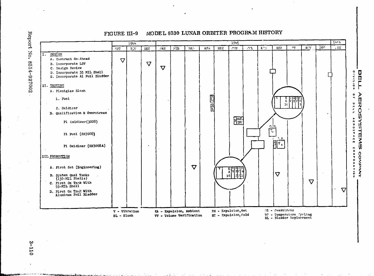
!:::i CD
FIG URE III-9 MODEL 8330 LUNAR ORBITER PROGAAM HISTORY
'" o t-l M'
Z o . 00 U1 ...... .... I ~ t.:: -l o o t.::
~ I
......
...... o
I. ~ A. Contract Go-Ahead B. Incorporate LSV C. Design Review D. Incorporate 55 MIL Shell E. Incorporate Al Foil Bladder
II. TESTING
A. Pley~glas Slosh
1. Fuel
2. Oxldl=~r B. Qualif1cation & Overstress
Pl ox1d1zer(3008)
Pl Fuel (S1l3008)
Pl Ox1dizer (SN3008A)
III. PRODUCTlON
A. First Set (on&1neering)
B. System Qual Tanks (130-MIL Shells)
C. Fil'at OX Ta:lk With 55-MIL Shell
D. First 0" Tal.): W1th Aluminum Foil Bladder
19b1l
~CT r~ .:\*
\]
I v .. Vibrat10n SL - Slosh
DEC
'V
••. ~J;(,.b·.-''''''~''''' '" "~.l ..... , .......... ,. vi, ''Nt\tIII\~~~'~'''>~0'2~;i«''<""v.~'~ ",:'!'~4"",.':'$)~"';"" ,;,N'~c-
.'An FEB ~·lA !.
'V
'.
'V
EA _ Expuls1on, Ambtent VV - Vol~e Verification
19o~
AP~ i-1J\ Y '''Of • 'j It .Tl'L
~ ~
~ I I
V 1/
v E !< r. A V I C
16 ? 1
../
FoR ... Expulsion.Hot. EC - r.xpuls lon,Cold
,.-" ,,;,-'tII" .''f. ,."~' ""--: ,~.,"",. ,.;" .,J
~-'; 5EF ~ N'.":'\, -
" IV e ~ t". :'_
I A . ! C,"\
1< 1
~ . ./
I ~ ',-
~~
'V \l
;"'\5 .. \'lVen;trl~r.s
Tr ... Tccpern turc .·yrll ng BL ... Blndder Hepbc(O:ent
1 (~ .. ·tJ
t:'F.r . ,-.....
[
I
!
'V
.
c OJ :: m ::: r ~ r o )~ m ~ )J ~ 0 • Ul '" -< ~ I"
~ ~ • m ~ ~ n Ul ~ 0 ~ 0 o 7 ~ ~
• 11 .. ;. (; Z z 0(
-oen lot' '" ," I"~ ;.4,1000. ..... .-t:'. ,., .. ~ j .... ~!_,.( ..... '_._ ...... ~ __ ._ ...... ' ... f!' ........ __ ..... ~~~ ........ _ ... ~ .... __ .Ao ... ___ ... __ ... ~. ?¥ .... 'n., "lb'ta
~. __________ BELL AEROSYSTEMS CQMP""NY _________ _
alVISION OF DE ... \. AEROSPACE CORPORATION
In February 1965, Boeing made two major changes to the program. The first of these was to incorporate a vibration requirement into the acceptance test of each dllliverable unit. The second change was the establishment of a test program designed to augment the command module qualification program in the area peculiar to the Lunar Orbiter mission. (The original intent of NASA/Langley and Boeing had been to conduct such unique testing at the vehicle qualification level.) A qualification test program e~l\1sisting of expulsion and vibration testing plus overstress testing consisting of thermal cycling, were incorporated into the program. It was required that these tests be performed on one fuel and one oxidizer tank. The test program started in April 1965 with slosh testing of one fuel and one oxidizer bladder in plexiglass tanks for the purpose of establishing slosh .nodes for vibration. Qualification testing was started in June 1965 and a bladder failure occurred in the oxidizer tank during vibration testing. As a result of this failure, vibration levels were revised by Boeing and the qualification program was restarted in July 1965. Qualification and overstress testing of the fuel and oxidizer tanks was successfully completed in September 1965. The test results are contained in Bell Report 8330-928004.
The fir!3t set of tank assemblies was delivered to Boeing in March 1965. After the f'ifth set had been delivered a hold was placed upon deliveries pending complett.on of qualification testing. During this hold period (July 1965), the Apollo program experienced stress eorrcsion failure in the o~idizer tank shells and the stress corrosion investigation was started. Because of very tight schedule requirements, Boeing was unable to wait for the investigation to be completed. The immediate way to solve the problem was to keep the stress below the danger point by thickening the OXidizer tank walls. A set of boiler plate tanks with 130 mil thick walls was fabricated and delivered in support of Boeing spacecraft testing. Meanwhile, the flight configuration oxidizer tank design was changed to incorporate a 55 mil tank shell. While this redesign was being accomplished on the oxidizer assemblies, the remaining fuel assemblies were completed and delivered to Boeing. In November 1965, the first oxidizer assemblies incorporating the 55 mil shells were delivered and 12 assemblies of this configuration were placed into production.
In January 1966, the oxidizer bladder was redesigned to include aluminum foil to act as a permeation barrier and prevent saturation of the N204 with nitrogen gas during the mission. Twelve assemblies of this configuration were completed and shipped, to Boeing, consisting of both new assemblies off the prodUction line and ass{'mulies retumed from Boeing for refurbishment. The laminate construction of this bladder consists of 2 mil TFE/1 mil FEP/1/4 mil Al foU/3 mil FEP. In May 1966, the last tank was shipped to Boeing, completing the project.
Report No. 8514-927002 3-111
__ ~Wl ______ tt ____________________________________________________________________ ~ ____________ ~ ___
_"_, _______ I'3ELL AEROSYSTEIVtS COMPANY _________ _
DIVISION 0" O~L~ AE.M05PAC£ eORPOIitATION
The Model 8330 tank assemblies were subsequently used on Lunar Orbiter Missions I through V. The fuel and oxidizer tanks performed flawlessly throughout the five missions in accomplishing a total of 29 velocity maneuvers. During Mission I and the 339 day mission IT, the propellants were allowed to flow until completely expelled. demonstrating e"'Pl::;:ion efficiencies of better than 99%. A summary of the propulsion system operation during each mission is presented in Table 111-2.
. .
Report No. 8514-927002 3-112
::110
i ;
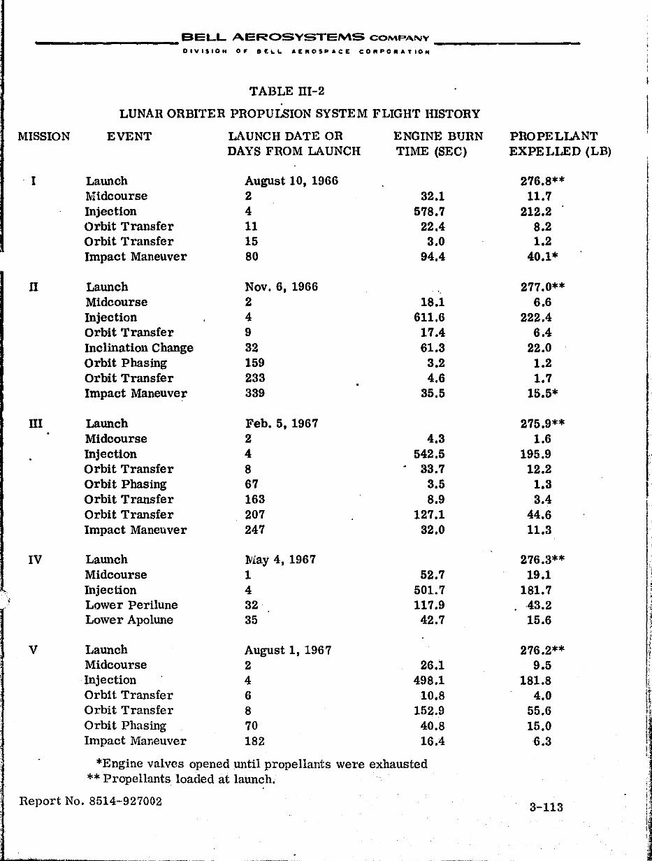
_________ BELL AEROSYSTEMS COMPANY _________ _
DIVISION 0,. D£LL AEROSPACE CORPOIIIATIO ..
TABLE 1lI-2
LUNAR ORBITER PROPULSION SYSTEM FLIGHT HISTORY
MISSION EVENT LAUNCH DATE OR ENGINE BURN PROPELLANT DAYS FROM LAUNCH TIME (SEC) EXPELLED (LB)
. I LaWlch August 10, 1966 276.8** Midcourse 2 32.1 11.7 Injection 4 578.7 212.2 Orbit Transfer 11 22.4 8.2 Orbit Transfer 15 3.0 1.2 Impact Maneuver 80 94.4 40.1*
n LaWlch Nov. 6, 1966 277.0** Midcourse 2 18.1 6.6 Injection 4 611.6 222.4 Orbit Transfer 9 17.4 6.4 Inclination Change 32 61.3 22.0 Orbit Phasing 159 3.2 1.2 Orbit Transfer 233 4.6 1.7 Impact Maneuver 339 35.5 15.5*
1lI Launch Feb. 5, 1967 275.9** Midcourse 2 4.3 1.6 Injection 4 542.5 195.9 Orbit Transfer 8 33.7 12.2 Orbit Phasing 67 3.5 1.3 I Orbit Transfer 163 8.9 3.4 Orbit Transfer 207 127.1 44.6 Impact Maneuver 247 32.0 11.3
IV LaWlch May 4, 1967 276.3** Midcourse 1 52.7 19.1
,. Injection 4 501.7 181.7 ~ ,
Lower Perilune 32 117.9 43.2 \ I
Lower ApolWle 35 42.7 15.6 ~~ I ~
V Launch August 1, 1967 276.2** i t
Midcourse 2 26.1 9.5 :
Injection 4 498.1 181.8 (
Orbit Transfer 6 10.8 4.0 (\ Orbit Transfer 8 152.9 55.6 ir .1
Orbit Phasing 70 40.8 15.0 ! Impact Maneuver 182 16.4 6.3 I ,
i' , *Engine valves opened until propellants were exhausted
** Propellants loaded at launch. j'
Report No. 8514-927002 ! 3-113 ! '
I:: 1 :
I 4
__________ BELL AEROSYSTEMS COMPANY _________ _
E.
DIVIS-ION OJ' OE~L. AEROSPACE CORPORATIO ..
ASSOCIATED PROGRAM HISTORIES
1. BELL MODEL 8460 - DESIGN CRITERIA AND QUALITY CONTROL STUDIES FOR TEFLON EXPULSION BLADDERS
This program was performed between late 1965 and the early part of 1967 for the NASA Manned Spacecraft Center under Contract NASw-1317.
In the early development phases of the propellant expulsion tanks for the Apollo program, a variety of bladder failures occurred which could not be readily understood. Therefore, this program was established to determine bladder design and quality criteria for evaluating the expulsion units of the Apollo-type tankage. Another purpose of this study was to provide timely support to the mainstream Apollo tankage programs with respect to bladder performance and to recommend modifications in design, operational and test procedures, or quality control, if these would benefit function or reliability.
An extensive review was made of bladder failures which occurred in the development phases of the mainstream tankage programs. This review, in conjunction with prior analytical and experimental studies performed at Bell, identified and defined the failure modes of the Teflon bladders and hence aided in . refinement of design criteria.
The following two failure modes were established as the prinCipal limiting factors in bladder service life:
• Biaxial tension forces develop in the hemispherical sections of the bladder during filling and pressurization if the bladder is incorrectly pOSitioned. These forces greatly extend local strains at fold and buckle sites to produce ruptures. In vertical tanks this condition is initiated by accumulation of bladder material at the bottom of the tank during expulsion. If the frictional resistance between the tank wall and the bladder is great enough, determined by the length of thl:: tank, the bladder is unable to lift completely during pressurization and remains displaccc1. This causes large strains in the upper hemisphere as pressure forces this part of the bladder to the tank wall. In horizontal tanks, the bladder tends to twist, thereby folding the material and reducing the available bladder volume. If the twist angle is large enough, severe biaxial tension strains develop in the bladder hemispherical ends upon complete filling of the tank. These failure mechanisms had been identified on the mainstream tank programs and the findings of this program aided in their clarification and helped to quantitively establish critical stress loadings which result in this type of failure.
Report No. 8514-927002 3-114
•
.' ~
__________ BELL AEROSYSTEMS COMPANY _________ _
DIVISION 0,- SELL. AEROSPACE CORPORATION
• Rolling of double fold motion is generated in the bladder during vibration, slosh, and fill and expulsion operations. This motion gradually fatigues the material at the site of the buckled fold. Since a large number of motion cycles are needed to develop a rupture, this failure mode is associated primarily with vibration.
Mechanical tests were performed which defined selected properties of Teflon-TFE, FEP and TFE/FEP laminates. The effects of temperature and fluid environment were particularly large in such tests as uniaxial tension and rolling of double folds. In the case of the latter tests, which were used to simulate the rolling of buckled fold failure mode in bladders, a large range of variation was found in the number of cycles to failure in given environments. The number of tests performed in this study did not permit statistical definition of the cycle life of the material in the various simulated and actual propellants, but the tests did indicate comparative performances. Material cycle life was high in Freon-TF, methylene chloride, and MMH; moderate durability was measured in N204; and a relatively low cycle life was measured in 50-50 fuel blend. Temperature had a pronounced effect on mechanical properties of the Teflon.
These findings resulted in the qualification, vibration and shock testing of the SATURN APS tankage with actual propellant in lieu of the alternate fluids originally specified. These tests, which were performed as part of this program, are described in Section III,C of this report.
The processing methods and controls used to fabricate Teflon bladders were reviewed and experimentation was conducted to determine the potential for increasing the service life of the material and obtaining improved uniformity. These studies indicated that quenching techniques can strongly influence the properties of Teflon-TFE. Rapid quenching after sintering decreased the crystallinity, which resulted in an order of magnitude increase in the rolling of double fold life of TFE in 50-50 fuel blend. The influence of other parameters such as spraying rates, sintering times, etc. were not investigated but it is possible that these may also have an appreciable effect on material constancy and performance in bladders~
This program is reported in detail in Bell Report No. 8460-933012.
Report No. 8514-927002 3-115
-<'. "
! ,
__________ BELL AEROSYSTEMS COMP~NV _________ _
DIVISION OF DELL AEROSPACE: COAPORATION
2. APOLLO TITANIUM - N204 STRESS CORROSION INVESTIGATION
The effort on this program was performed by Bell under subcontract with the Space and Information Systems Division of North American Aviation under NASA Prime Contract NAS9-l50. The original titanium - N204 stress corrosion problem occurred at Bell; however, it soon became apparent that this was an industry wi.de problem of serious magnitude. Bell was designated as the focal point for the investigation; however, the NASA agencies, Apollo prime contractors, and many other organizations materially participated in the program.
The failure of SMO Unit Y-2 (Shell SN 5) after 23 days exposure to N204 (MIL- P-26539) during the Model 8271 development program was the starting point of the stress corrosion program. A detailed investigation of this failure identified the cause as stress corrosion. The original theory was that the stress corrosion may have been caused by unintentional sensitizing of the titanium during fabrication of the tank shell.
A comprehensive series of tests was initiated on ten titanium 6Al-4V tank shells to determine if the initial failure was a random occurrence or if the titanium alloy and Specification N204 were incompatible. The tell tank shells were selected based on their fabrication dates so as to have shells fabricated both before and after failed shell SN 5. The selected tank shells were assembled without bladders and loaded with Specification N204' Eight of the ten tank shells failed in test and the remaining two shells were burst tested. One of the burst .test shells ruptured above the design pressure but the second shell failed below the design burst pressure. Evidence of stress corrosion was found on the inside surface of all ten tank shells. The only differences noted among the shells were crack intensity and crack density.
The ten-tank storage program proved that a stress corrosion problem existed between the titanium 6Al-4V alloy and Specification N204 and established that the problem was not random in nature. The stress corrosion investigation at Bell was then directed to resolve the problem by determining the cause of the stress corrosiOll and/or to determine a practical solution to the problem.
Allison Division had successfully stored SpeCification N204 in titanium 6Al-4V alloy tanks. Compared with the failure at Bell (both using Specification N204). the Allison success indicated that the Bell fabrication process or handling used for the Apollo RCS tank shells was introdUCing some factor which resulted in stress corrosion. Chlorides were a prime suspect based 011 previous stress corrosion test results.
Report No. 8514-927002 3-116
•
(
__________ BELL AEROSYSTEMS COMP""'Y _________ _
DIVl510N OF" BELL AEROSPACE CORPORATION
Bell Aerosystems Company representatives.toured various manufacturers' facilities to discuss the stress corrosion problem.and several metallurgical meetings were held at Bell. Knowledgeable persons from government agencies. aerospace companies. and universities were present for discussions on the problem.
As the result of this work. several tank shells were treated and exposed to Specification N204' The titanium surface treatments evaluated included air furna(:e oxidation. anodizing. and Teflon coating. Only the Teflon-coated tank shells showed any promise of meeting the 30-day storage requirements of the Apollo RCS propellant tanks. The test effort also showed that galvanic action (aluminum/titanium couple). annealing. cleaning method. and heat treatment were not significant factors in the stress corrosion problem. Temperature was found to be an accelerating factor while stress level was found to be a lesser factor.
During this time. NASA/Langley Research Center undertook the evaluation of inducing residual compressive stress as a solution to the stress-corrosion problem. NASA/LRC demonstrated that glass bead peening of the tank shell internal surface was a candidate as a solution to the stress corrosion problem.
At the same time that these tank tests were being accomplished, Bell . developed and utilized stressed titanium specimen te~ting which was representative of the tank shell failures. The stressed specimen testing evaluated titanium surface treatments and N204 additives. The results of the stressed titanium specimens in Specification N204 demonstrated that titanium surface treatments did not eliminate stress corrOSic.:l (with the possible exception of Teflon coating) and that fabrication processes were not significantly contributing to the cause of stress corrosion. The stress corrosion of commercially pure annealed titanium as well as material from an Allison tank demonstrated that the problem was not the result of the fabrication used on the Apollo RCS tank shells. Further evidence that the stress failure of Apollo RCS tank shells was not the result of fabrication processes was demonstrated by the failure of one Surveyor and two Gemini titanium tank shells at Bell after exposure to SpeCification N204 at Apollo stress and temperature requirements.
The possibility of determining an inhibitor which could be added to Specification N204, to stop the stress corrosion,was considered as a possible solution to the stress corrosion problem. The stressed titanium specimen testing program included the evaluation of various additives; i.e .• water, nitric acid, nitrosyl chloride. silver nitrate, etc. Only limited testing of the.se additives was accomplished at the time NO was found to be an effective inhibitor, but some of these additives (e.g., nitric acid) also appeared to be effective in inhibiting stress corrosion.
Report No. 8514-927002 3-117

__________ BELL AEROSYSTEMS COMP .... NY _________ _
OlVISION 0,. OE~L AEROSPACE COAP'OAATION
The results of the test specimen and tank stress corrosion testing indicated that the stress corrosion attack of titanium was not the result of fabrication since commercially pure titanium was found to be as susceptible to attack as the 6Al-4V alloy. The fact that Bell Aerosystems-fabricated tanks did not fail in test at North American also indicated that l,>rocessing was not the source of the stress corrosion problem. Greater attention was then given to the chemistry of Specification N204' Once again Bell made use of available information by contacting and meeting with knowledgeable persons from governIl''lnt agencies, aerospace companies, and universities.
The chemical approach considered not only the chemistry of Specification N204,but also the probable reactions occurring at the titanium surface. The principal goal of the chemistry approach remained the same as that held previously, which was to determine the cause and/or solution for the stress corrosion problem.
The presence of nitric oxide in Specification N204 was found to be a solution to the stress corrosion problem during the stressed specimen test program. A comparison of this finding with a check o~ the N204 used with the tanks that did not fail in test at North American Aviation/S&ID and with tanks that did fail in test at Wyle Laboratories, NASA/MSC, and Aerojet substantiated this fact.
A series of tank shell tests was initiated at BeH to confirm that the presence of nitric oxide did lr.deed eifectively inhibit stress corrosion of the tank shells. Three tank shells were tested and all exceeded the 30-clay requirement at temperatures in excess of the required 105 of. .
To verify that the stress corrosion solution was not random in nature and that the presence of the Tefloll bladder did not negate the solution, two bare wall tank shells and two tank assemblies with bladders were tested with N204 containing 0.030% NO. The test results verified that the presence of nitric oxide did inhibit the stress corrosion failure of the titanium 6Al-4V tank shells and that the presence of the bladder had no discernible effect.
This investigation culminated in the issuance of NASA Specification· MSCPPD-2 for procurement of N204 with controlled NO content.
The detailed results of the tests and investigations are contained in the four volumes of Bell Report No. 8271-928060.
Report No. 8514- 927002 3-118
, I i I I
I ,
__________ BELL AEROSYSTEI''\S COMP"NY ______ -'-__ _
DIVISION 0,.- DE~L AI[AOSPACE CORPORATION
3. BELL MODEL 2312 - SERVICE 1\1ODULE ALUMINUM TANK SHELL
This program was performed from October 1965 to December 1966 under 0>ntract NAS9-5330 for the NASA Manned Spacecraft Center. The effort included the design, fabrication and test of one tank Ishell plus production of four deliverable units.
The existing titanium command and service module RCS propellant tank shells arc designed to ha':e the lightest possible structural weight. As a result, these thin wall shells are not capable of withstanding complete internal evacuation because of low buckling strength. This program was established to develop and fabricate an aluminum alloy tank shell which was capable of withstanding complete internal evacuation and designed to be functionally and dimensionally interchangeable with the sen'ice mcdule RCS oxidizer tank shell.
The design and fabrication of one test and four deliverable tank shells was completed. Detailed weight estimates showed that the 6061 T6 aluminum alloy oxidizer tank shell would be approximately 1.40 lb heavier than the present 6Al-4V titanium oXidizer tank shell.
The structural adequacy of the aluminum shell was demonstrated by successful completion of an internal proof pressure test to 331 psig and an external proof pressure test to 22 psid. The burst test requirement of 372 psig was surpassed and the pressure was increased to 422 psig before failure occurred in the form of a small leak in the circumferential weld. The leak was £ealed and an ultimate external pressure test was completed which successfully demonstratE,d that the external pressure requirement could be met. After passing the specified extel'l1al pressure of 30 psid, the test was continued until an abrupt change in the slope of volumetric expanSion versus external pressure occurred at 41 psid.
The design, fabrication, delivery, and test reqUirements of this program were successfully completed and a detailed account is presented in Bell Report No. D2312-950001.
Report No. 8514-927002 3-l19
, , , ' I
i
I I I I
i ! I I I . ! .':::
i
I I I
I' I i,
•
I
__________ BELL AEROSYSTEMS COMP"",,.,. _________ _
OIVISION OF DELL AEROSPACE CORPORATIOt'
4. BELL MODEL 8508 - NITROGEN TETROXIDE EXPOSURE TEST PROGRAM
This test program was perform cd in the early part of 1967, under Contract NAS9-6660,for the NASA Manned Spacecraft Center. The testing was designed to provide added confidence in the ability of the Apollo grade (green) N204 to prevent strcss corrosion.
Two service module tank assemblies and a command module tank without a bladder were subjected to N204 storage conditions which simulated the more demanding aspects of a space mission in terms of potential problems with stress corrosion.
The two service module tank assemblies (R1 and R2) were loaded to approximately 50 percent capacity with N204 and pressurized with helium on the gas side. This condition allowed the N20L] t.o permeate through the bladder and contact the highly stressed (90 ksi) areas of the thanium shells. These two units were stored for 30 days to determine if a large ullage volume (increased bladder permeation) would increase the possibility of stress corrosion of titanium. at the specified test conditions. The presence of gas bubble formation within the bladders during the storage period was also studied. Tank R1 was tested at constant elevated temperature and pressure,and tank R2 at constant elevated pressure and variable temperature.
Test Unit R1 successfully completed 30 days of N204 exposure testing at a constant pressure of 288 ±28 psig and a constant temperature of 100 ±5°F. A gas bubble formed during testing as verified by the post-test X-rays.
Test Unit R2 successfully completed 30 days of N204 exposure testing at a constant pressure of 302 ±28 psig and a variable temperature of 60 ±5°F to 100 ±5°F. A gas bubble formed during testing.
The command module tank without a bladder (Unit R3) was half loaded and subjected to a 30-day storage and slosh test series to evaluate the possible effects of stress corrosion on titanium from propellant in motion at elevated temperature and pressure. It was considered possible at this time that the success of the Apollo grade N204 under static exposure conditions was due to protect~ve films formed on the titanium and that these films could be washed off by liquid motion during a mission.
Test Unit R3 successfully completed 30 days of N204 exposure testing at a constant pressure of 388 ±38 psig and temperature of 100 ±5 of. The test unit was sloshed each normal working day at a rate of one cycle per second at 2 inches double amplitude (which is equivalellt to 0.1 g loading). The test unit completed approximately 536,124 cycles or 1,072,128 sloshl?s during the test period.
Report No. 8514-927002 3-120
__________ BELL AEROSYSTEMS COMPA-NY _________ _
OIYI$ION 0" OIEL.L. AEROSPAC;:E CORPORATION
The three units were subjected to hydrostatic burst test to determine the effects of prolonged nitrogen tetroxide e"."posure on titanium tank shells. The burst prcssures were as follows:
Minimum Required Actual
(psig) (Psig)
Unit R1 (SMF) 372 650
Unit R2 (SMF) 372 603
Unit R3 (eMF) 540 1074
Metallurgical, chemical, and X-ray evaluations were made before, during, and after the testing to provide data in the following areas:
• Tank material before and after test
• Bladder position before and after test
• Propellant quality during loading and draining
• Analysis of permeants into gas
• Analysis of gas into propellant
• Bubble formation
Metallurgical analyses of the tank material showed no evidence of stress corrosion cracking or degradation of tank shell integrity. This was verified by the burst test results.
X-rays showed movement of the bladders to the wall confirming the results of chemical analyses and models describing bubble formation and growth. The bubble, which formed during test prior to propellant saturation, was rich in helium; however, quantitative analysis of the phenomenon was rendered impossible because of changes in the temperature and pressure during the test.
The only deterioration noted in propellant quality were decreases in NO (nitric oxide) content and an increase in dissolved helium content. The NO decay appeared to be a matter of sampling procedure and the results were within the limits of cl'.'Pcri ~lental accuracy.
Permeation of the bladder by propellant was obvious within four hours.
Report No. 8514-927002 3-121
.1:". 'i I
· "
I
__________ BELL AEROSYSTEMS COMPA.N .... _________ _
DIVISION OJ' OE:,.L. A!tR05PACIt COIIIPOiJIATION
The det.ailed test and analytical results, contained in Bell Report No. 8508-928002, showed no problem on exposure of highly stressed (90 ksi) areas of titanium 6 A1-4V tanks to permeants from Apollo grade N204 (Specification NASA-i\ISC-PPD-2A),within the limits of the test program.
, ,
Report No. 85ltt-927002
- -:- -,, __ , __ -', __ ".,~. .0'._
3-122
__________ BELL AEROSYSTEMS cO"v\p.'''-lV ___ .. ". _____ _
DIVISIOH 0" BELL Ar:II'OSPACIE CDMPO .... TION
5. BELL FUNDED R&D BLADDER i\1ATERIAL PROGRAMS
a. Purpose
Apollo tankage studies and eXllerience showed that the Teflon expulsion bladders have limitations in cycle life during expulsion and vibration,and resistance to permeation of pressurizing gas and propellant. Increased cycle life is desirable to increase the reliability above that presently attainable with Teflon bladders; permeability is desirable to prevent the pressurizing gas from accumulating in the propellant side of the bladder. To ~chieve these features, nell has been investigating improved and new materials and methods such as elastomers, improved Teflon, and penncation barriers.
b. Elastomeric Bladder Material
(1) Oxidizer Application
The need for an elastomeric material compatible with N204 and possessing the desired elastic strain capability for repeated folding and buckling, without material damage, resulted in intensive effort by Bell in development of nitroso rubber expUlsion bladders. The development of optimum techniques and methods for compounding nitroso rubber for bladder application has been actively pursued since early 1966. This effort resulted in the fabrication of a 10-inch diometer spherical
. bladder by a spray dispersion technique. A photograph of the bladder is shown in Figure III-10.
Although nitroso rubber yields the desired improvements in bladder cycle life, this material is highly permeable to N20 4, helium, and nitrogen. Thus, the effort in 1967 concentrated on the development of a nitro so rubber bladder having a metallic foil permeation barrier. The major problem encountered was insufficient adherence of the rubber bladder to the metallic foil. Although some degree of success was obtained, the adhesion problem was not completely solved and efforts were shifted in 1968 to the incorporation of a proprietory plastic permeation barrier (Vapolock) into the nitroso rubber. This barrier reduces the permeation rate of a nitroso rubber bladder,10 fold. The 1968 prog'am will culminate in the fabrication of several Nitroso/Vapolock 10-inch diameter bladders which will be subjected to storage and expulsion tests.
(2) Fuel Application
For several years elastromeric materials have been investigated for fuel bladder use. These materials include ethylene propylene copolymer (EPR), ethylene propylene terpolymer (EPT), and butyl rubbers. These elastomers were subjected to specimen compatibility tests in MMH and 50/50 fuel blend for
Report No. 8514-927002 3-123
I
i I i
I· i
I , I I·
!
1
•
..... ""<) l-·W .... ... J"t,,!! ',( "i"" II ".-,.'-j. Nt""""' .. ,·}" :f_' .. " ·t '"'Xl s '''.lt' II "P" Sf ",neSSH'· -. tf?~vr _3 '£'3511-1 m [0'-' U\'tI'MW-'.j q1 \trW-Un PS5 c ," gat t_ n $' f, -, It Cd ('
hj (II
'g '"I .... ~ o • co en t-'
t <"1) I.\:l -'I o ~
CII) I
~ ...,--. ~'.
11 r , t ,! ~ , ~! r' _, t "
~
\ "
1 I J ~ 1 I
t \ ),,' \ r
" " / ..... .I
;t.'/ (
~ . ~ E.., t". r-' c-")"W ',-:.,!.~ '1".-' ,: , . ~ "a-a)" -11"'-, • x_ .'
Redundant Film Bladder
'--,
I i j
I 'I 1 I
l
1 ei j ~-~---
.t.-... ' ... ·~ ..... ~·~.-i..~-..",wtf L. L * l' I! t" '?t ?,: - N ;:
Nitroso Rubber Bladder
~. tI'oo ,'FIGUREin-10 TYPES OF EYFULSION BLADDER COK~:Po§i:TION~i:
<~;:,'<'.' .~~:'-;,~'-,;i-;.-';,; 4""i't j; ,<, '
".; _"JI;, 'i ... ' _,,_,".'.'<'.."--"'"
o III -: rn :: r ~ r o ) ... m ~ iJ ~ 0 • Ul M -< ~ Ul ~ -i, : m n ~ '"
n Ul 0 · () ~ 0 ~ ~ · ] ~ p 0 Z z 0(
-
__________ BELL AEROSYSTEMS COMPANY __________ _
DIV'S~ON 0,. DELL. AENOS-PACe CORPORATION
I-day, 7-day, 28-day, and 63-day storage periods at 80°F. EPR and butyl rubbers were found to be equally satisfactory for use with fuel,except that EPR exhibited greater durability. E PT was found to be unsatisfactory. In addition to the specimen compatibility tests, 10-inch diameter spherical and hemispherical bladders were stored for 30 days in MMH at 80 o F,with no adverse effects.
Based on the results of the material studies, work was continued in 1967 and 1968 in the development of EPR and butyl rubber bladders. Although some degree of success was achieved in incorporating a metallic barrier into these bladders, the metallic barrier was dropped in 1968 so that the full effort could be concentrated on the incorporation of Vapolock into the EPR bladders. To date, conSiderable success has been achieved and the 1968 program will culminate in the fabrication of several10-inch diameter, hemispherical EPR/Vapolockbladders which will be used for propellant storage tests.
c. Improved Teflon Bladder Material
In an attempt to develop a Teflon bladder with lln improved cycle life, redundant and codispersion films were' investigated. The redundant film bladder, shown in Figure 111-10, consisted of three-plies of TFE with graphite laminated between each ply. This provided for ply-to-ply slippage which, in turn, m.inimized sharp creases and folds. In addition, the use of graphite was intended to keep the plys intact and thus prevent the entrapment of gas between the plys. Results of specimen tests showed that the redundant film construction exhibited a cycle life three times greater than the 6 mil TFE/FEP laminate. The redundant film helium permeation rate was eqUivalent to that of the laminate,but the N204 permeation rate was five times greater. Because of the promising cycle life, an SMF size redundant film bladder was fabricated and successfully subjected to vibrati.nn, 14-day N204 storage, and 1Q..expulsion cycles. However, extensive delamination and entrapment of gas occurred between the plys. For this reason,the redundant film bladder concept has been discarded.
The codispersion material is a mixture of TFE and FEP sprayed and sintered together into a uniform film. Specimen testing of 3%, 5%,and 10% FEP loadings indicated that the only codispersion film that offered an advantage in fatigue cycle life,over the TFE/FEP laminate, was a codispersion film with a FEP loading of 5%. How:lVer, the helium permeation rate of the 5% FEP codispersion film was four times greater than that of the laminate, which made it undesirable as an alternate film construction.
Report No. 8514-927002 3-15;'5
,
:.;
r I
-- ---_._------------
__________ BELL AEROSYSTEMS COMPA.NY _________ _
DIVISION OF DELL AEROSPACE CORPORATION
d. Permeation Barrier Development
(1) Metallic
A technique for fabricating a Teflon bladder with a metallic permeation barrier was successfully employed during the Lunar Orbiter program. Company-sponsored research has established a +35 of expulsion cycle capability and a 17 expulsion cycle life capability at ambient temperature for the Teflon/ metallic foil bladder. At the completion of 17 cycles with N204' the bladder lealmge rate was 12 cct'15 minute of helium compared to 80-90 cc/15 minute of helium for an equivalent size TFE/FEP laminate bladder. Prior to cycling, the leakage rate was zero. The metallic perneation barrier effort is continuing with emphasis on the development of methods for depositing uniform nonporous metallic coatings on nonmetallic substrates.
(2) Nonmetallic
Experimental work in 1966 and 1967 resulted in the development of a proprietary plastic permeation barrier (Vapolock) which reduces the permeation rate of a Teflon bladder by a factor of 7 to 10. Development of optimum bladder/barrier fabrication techniques is continUing. The 1968 program will yield both llitroso and EPR bladders with the Vapolock permeation barrier.
Report No. 8514-927002 3-126
"
"
__________ BELL AEROSYSTEMS COMPANY __________ _
DIVISION O~ DELL AEROSPACE CORPORATIOff
SECTION IV
MANUFACTURING AND QUALITY CONTROL
At the inception of the Apollo tankage programs the plan for the command and service modules was to have all fabrication within existing capabilities for manufacturing and inspecti<m techniques because of the extremely tight schedule limitations, In reality, the state-of-the-art had to be advanced in many areas because of the stringent specification reqUirements and continuous refinements to lower the weight and increase the reliability of the tankage.
The existing technology base at this time was the experience with the Model 8101 Agena SPS tankage,which was a low production item. The Apollo type tankage necessitated advancements in the following areas:
High Production Rates - The need for high production on a tight schedule basis require(; fabrication and inspection of components on an assembly line basis with elimination of all "model-shop" type operations. Special tooling, fixiuring, and inspection equipment were devised to give repeatable results.
Titanium Shells - These were the thinnest-walled titanium pressure vessels known at that time. Fabri-. cation, inspection, and handling techniques were refined to assure compliance with the stringent requirements and to minimize sCl"appage due to rejection or damage.
Teflon Bladders - Although the fabrication process was essentially the same as for the Agena SPS bladders, the Apollo tankage requirements led to much tighter fabrication control and many advancements in inspection techniques.
Diffuser Assemblies - The difficult welding and critical drilling operations required for this assembly,coupled with numerous design changes,resulted in continuous
. refinement of the fabrication and inspection operations. The use of the stainless steel-to-aluminum bimetallic joint added to the complexity of this component.
Report No. 8514-927002 4-1
I
i I !
I I
___________ BELL AEROSYSTEMS COMPANY __________ _
DIVISION OF DELL AEROSPACE CORPORATION
Assembly and Acccptance Test - Although Bell had produced other tankages with equally stringent cleanliness requirements, the production rate demands and configuration of the Apollo tankage necessitated major refinements in facilities, personnel training and specialized test and handling equipment.
Identification and Traceability - The stringent identification and traceability requirements required implementation of special procedures and controls to maintain a closed loop system on all aspects of the raw material, special processing, fabrication
. and testing.
The major fabrication problems were solved during the early stages of the command and service module programs. The solutions and advanced techniques were automatically implemented on the programs which followed.
A. Tank Shell Fabrication'
The tank shells for the eM, SM, LM, SIVB, and LO tank assemblies are fabricated from titanium alloy. The 12.5 inch inside diameter is common to all configurations and the sheUs vary in length from 17.3 inches foI' the eMF to 38.8 inches for the Ll\'l oxidizer. The eM/LO tanks are made by joining two elongated hemispheres while the other configurations require the addition of a cylindrical section. The tank shells for the command and service module and the lunar module tankage were SubcOlltracted to Sargent-Airite. D-uring the early stages of these programs Bell developed an in-house capability, for fabricating titanium shells and later manufactured all of the shells for the Lunar Orbiter and Saturn !VB.
1. Processing Sequence
Material for the Apollo shells is forged from billets of titanium 6A1-4V alloy which are rolled from ingots produced by double consumable electrode vacuum arc melting. Eacl~ billet is cut into forging multiples which are serialized and recorded as to location in the billet.
The forging multiples are heated to the required forging temperature with the temperatures and reduction ratio controlled to produce as fine a grain size as is practical. Specification limits are for equiaxed primary alpha , particles to be predominantly ASTM No. 8, or finer, as determined by ASTM Practice E1l2. The hemispherical components are forged in a closed die and the cylindrical components are made from upset and pierced discs which are extruded and rolled to cylindrical shape.
Report No. 8514-927002 4-2
-:to.
.<,
__________ BELL AEROSYSTEMS COMPANY _________ _
DIVISION O~ BELL. AEROSPACE CORPORATION
The forgings are completely inspected and partially machined to remove excess material in heavy sections prior to solution heat treatment and stress relieving. Solution heat treatment is made at 1725°F for two hours followed by a water quench. Stress relieving is at 950°F for a maximum of two hours followed by air cooling to room temperature. The cylinders are rough machined before stress relief while the hemispheres are rough machined after stress relief.
The outside and inside diameters of the hemispheres are rough machined and then the inside diameters finish machined. The closed end hemisphere is finish turned on the outside diameter. The open end hemisphere is profile milled on a vertical mill and the flange contour is formed on a Hydrotel. The boss is then formed on a vertical mill, the outside diameter is finished on a tracer lathe, and the flange and gas port are drilled and tapped. The cylinders are rough bored and turned and finish bored and turned on an engine lathe with tracer. The D.D. of the cylinder has a profiled weld lip for fuSion welding to an identical lip on the hemispheres. Measurements are made after each machining operation and recorded in t~rms of amount of metal removed per surface to assure that all surface contamination is removed during machining.
The parts are cleaned in preparation for welding to remove all surface defects and sub-surface conditions of oxidation, scale, grease, etc. The cleaning process includes submersion of components in a hot alkaline bath, scrubbing, rinsing w.th water, submerging in a 35-45% nitric acid bath, spray washing, and forced-air drying.
All welding is done on parts in the solution treated and stress relieved condition. The cleaned components are assembled in the weld chamber and the weld areas are inspected to assure the absence of all foreign particles. For the welding operation an expandable backup fixture is used and locating pins are employed to control alignment. Parts are first tack welded in a vacuum-purged inert atmosphere welding chamber. Tack welds are made in 16 places,approximately equally spaced using a skip sequence. After tacking, the assembly is TIG fusion welded with one continuous single pass. This procedure is performed so that craters or other stopping defects are prevented.
After welding, the assembly is cooled under inert gas flow before removal from the welding chamber. The backup fixture is removed and the shell assembly is inspe'cted. Inspection criteria for the weldment include mismatch, penetration, porosity, bead width, buildup, and drop-through. The tank shells are then alkaline cleaned, water rinsed, placed in 35-45% nitric acid bath, spray washed, and dried.
Report No. 8514-927002 4-3
, I
I I
I I t f:
I ~ !
I ,
" I I !
I t I I
! ;
•
J
I I
I
__________ BELL AEROSYSTEMS COMPA.NV _________ _
DIVISION OF" DELl. AEflOSPACE CORPORATION
The shells are aged at 1050 0 F for 2 hours to meet required properties. Forgings for each shell are selected on the basis of similar heat treat response and chemical composition, so final mechanical properties will be uniform. After aging, the shells are removed from the furnace and allowed to cool to room temperature.
A final surface treatment is performed to remove sufficient metal after aging to assure freedom from contamination resulting from aging. The process used is a modified 'Ti-Brite' precess which is an electrolytic method of removing high temperature oxides and scale from titanium and its alloys.
After 'Ti-Briting',the shell flanges and Losses are finish machined to insure accuracy of mounting dimensions. The nut plates on the flange are riveted in place after final shell inspection.
Final inspection and acceptance test is made to insure conformance tc. the Bell Drawing requirements. It consists of the following:
Dimensional Check Hydrostatic Test at proof pressure Helium Leak Test Radiographic Inspection Fluorescent Penetrant Inspection
2. Fabrication Problems
It is believed that the Apollo tankage became the thinnest walled titanium pressure vessels ever fabricated on a production basis. Because of the relatively thin walls, imperfections such as nicks, dents, or scratches could not be tolerated. Special motivation training of personnel,and the use of special handling fixtures and containers, resulted in negligible loss or damage to tank shells or details despite the many handling operations required for fabrication and inspection.
Numerous problems were encountered during fabrication of the early command and service module shells. The following is a summary of fabrication problems which occurred during the early manufacturing period:
a. Wall Thickness
Maintaining the wall thickness of .022 +.000 -.005 inches resulted in a 25% rejection rate. The following corrective action was implemented
Report No. 8514-927002 4-4
i I • i !
, I
I I
J
I 1
I I I
i
,
I
I·' I- -
__________ BELL AEROSYSTEMS COMPANY _________ _
DIVISION 0" DELL. A.En05PIt,CE CORPORATION
which shortly reduced the rejection rate to 10% and eventually to less than 1% over the long-term:
Use of vacuum chucks to hold the thin wall hemispherical sections firmly in place during final machining operations.
Use of contour templates to assist the machine operator during intermediate setups.
Stress relieving of the parts after partial machining.
Thickness measurement of the hemispherical sections in 12 quadrants spaced one inch apart.
Use of special deep-throat micrometers as an added check of the Vidigage readings.
h. Mismatch
Mismatch between thE, mating surfaces of the closed-end and open-end hemispherical sections (and between the cylindrical section on service module tanks) resulted in a rejection rate of 33% on the first 30 shells fabricated. The following action reduced this rate to 15% within 3 months and eventually to less than 2%:
Use of internal and external backup rings to align and hold the hemispherical sections firmly in place during welding.
Implementation of speci!'J tools and techniques for proper measurement of misma.tch after welding.
Use of special sizing rings to selectively measure and mate cylindrical and hemispherical sections.
c. Porosity
Rejection due to porosity. pore spacing. and inclusions amounted to more than 50% during the early stages of shell fabrication. The following were some of the pertinent factors that resulted in lowering the rejection rate to less than 5%:
Development and careful monitoring of speCial cleaning processes .
. Establishment of a time limit between final cleaning and welding.
Report No. 8514-927002 4-5
•
,
__________ BELL AEROSYSTEMS COMPA"-I'V ___________ _
DIVISION OF" DELL. ACA05P,"C£ CORPORATIOH
Preparation of the weld area by draw filing to remove oxide scale.
Special wrapping and packing procedures to maintain cleanliness level of parts awaiting welding.
Training and certification programs for welders and inspection personnel.
Establishment of rigid control of chemical composition and cleanliness level of cleaning solutions.
d. Weld Bead Height, Width and Drop Through
Failure to meet these requirements caused rejection rates in excess of 20% at the beginning of the shell fabrication process. They were reduced to less than Z% as a result of the following actions:
Refinement of the step-by-step weld procedure to tightly control voltage setting, current control, rotational speed of weld, and vacuum chamber environment.
Weld operator training and certification.
Tack welding at specific intervals prior to full single pass weld.
B. Bladder Fabrication
The bladders used on the Apollo type positive expulsion tanks are fabricated from laminated Teflon TFE and FEP, by Dilectrix Corporation, using the spray dispersion technique. The fabrication of the bladder is a rather unique process which consists of spraying and curing thin layers of Teflon onto an aluminum mandrel. After the layers are built up to the required thickness, the mandrel is removed chemically.
1. Processing Sequence
The soft aluminum mandrel is made up of two or three spun sections. These sections are welded together and the entire exterior is polished to a 32 RMS finish. The outside diameter, overall length and concentricity are precisely controlled since these dimensions control the size and shape of the completed bladder. The length and diameter of the mandrel are slightly oversize to compensate for bladder shrinkage encountered when the mandrel is disso~ved,
Report No. S{)14-927002 4-6
• --<.; i ',-
__________ BELL AEROSYSTEMS COMP,'""Y __________ _
D&V~SION Of' DELL AEROSPACE CORPORATIOH
The bladders are fabricated on an assembly line in a level C clean room environment. A ma.'Cimum of three bladders may be, processed simultaneously as an individual lot. A cylindrical mandrel is processed with each lot to produce a test "pipe" which is representative of the bladders in that lot, The test pipe is subjected to dp.structive testing to determine the physical properties of the lot of bladders which it represents.
The Teflon TFE is sprayed on the mandrel while it is rotating in a horizontal chuck. Each spray application deposits a layer approximately .00025 inches thick and, after each application, the Teflon is allowed to partiall!, air dry. The Teflon-coated mandrel is then cured at approximately 670°F in a temperature controlled oven. After drying, it is removed from the oven and dlowed to cool in preparation for the next application of spray dispersion. Approximately fifteen spray applications of the TFE laminate are used to attain the required 3 mil minimum thickness. Thickness measurements are made with a Dermitron and Permascope at specific intervals to assure completion to drawing thickness reqUirements. The spray cycle of applying the 3 mil of FEP is the same as for the TFE except that the oven-temperature for curing the FEP is approximately 560°F. When the required 6 mil thickness is attained, the mandrel is removed.
Dissolving the coated mandrel is accomplished using a caustic solution and sodium gluconate. Proper amounts of these chemicals are measured out into charges which are added to the dissolving tank slowly to limit the tlilmper-.ture of the dissolving solution. After the mandrel is completely dissolved, the
bladder is removed and cleaned. After cleaning, the bladder is inflated to approximately 1/2 psig and dimensional measurements are checked with contour templates. At this point in the manufacturing cycle, the undersized bladders for LM and SIVB are subjected to an additional sizing operation. Upon completion of the sizing operation and corresponding dimensional inspection, the bladder flange is trimmed and the flange mounting holes are punched. The bladder is then placed in a special holding fixture, pressurized to 1 psig, and the entire surface is vi~ually c.hecked for leakage -first by water immersion and then by helium mass spectrometer leak tests.
After the leak test the bladder is visually inspected in accordance with a detailed procedure with the help of visual aid samples of actual bladder film which define acceptance and rejection criteria.
In preparation for shipment the bladder is placed into a 'polyethylene bag and a clean commercial rubber balloon,of suf~icient size to support the entire bladder,is inflated inside the bladder to prevent collapse during shipment and storage.
Report No. 8514-927002 4-7
,,5 •.•. ,,~-*F!I.74 __ ,·.$£U ':~"'.fi.5! .. OJ . .)~. ; 9A ;iY.Q.(, tAue; c .• Ol.c m .4 .. ~ • _. IF¢. ( .4".
,
.~
"! -,
"
'.
::.i
,~
•• '\ 1': r'-:, I,'~ · ,-; -, -;-, ., .. , ::1 ;~ ~ , • ',~.
t
· " i; , .,-,;
· :ii ,~ 'a ~
, .~ ~)
, .~~ -5;
i \!\
'. :':s; , . ~ 1 , ~,
'.
f .J
___________ BELL AEPOSYSTEMS COMPJ".NY __________ _
01 ..... 510 .. OF" nELL AERO$PACE C.ORPORATION
2. Fabrication Problcms
At the beginning of the Apollo program, bladders were of the 3 mil 3-ply constru<.:tion. Several fabrication areas at Dilectrix had to be improvpd to maintain the level of cleanliness required on the Apollo program. Since the three individual plies had to be assembled and bonded at the butt and flange ends with no particulate matter between the plies, special laminar flow work areas were employed. The bonding or heat sealing of the ends required the d0signing of special dies and sealing techniques, as well as destruetive testing of material s.1mp)'Js ,to assure repeatable and adequate bonding of all bladders. To assure strict compliance with the critical dimensional requirements of the bladder, special fit tanks were used and each bladder was tank fitted at the supplier's facility as part of final inspection. In the summer of 1964, the bladder design was changed to 6 mil single~ply and an entire new set of process and quality control procedures was generated.
Changes in various contractors' resident quality representatives caused a fairly high rejection rate of bladders in the final assembly stage because the acceptability of a bladder was based, iR part, on visual inspection and consequently on judgment which varied between individuals. This lack of firm, positive acceptance and rejection cri"eria resulted in Bell and Dilectrix collaborating on preparation of a set of visual aid samples of acceptance and rejection criteria. A special procedure, Report No. 8339-928006, was written and a special illumination inspection fixture was developed to establish the same set of standards of inspection both at Bell and at Dilectrix. Implementation of these procedures resulted in a marked decrease in bladder rejection. .
In the latter part of 1965, during the measurement of test pipe thickness at Bell, it was discovered that several test pipe specimenR were slightly under the minimum 6 mil thickness requirement. Micrometer measurements were made on various bladders associated with the thin test pipes and the bladders were also found to be slightly under the drawing thickness requirements. An investigacion disclosed that bladders that were exhibiting these defects were fabricated during a peak production peliod which required maximum loading of the electric curing ovens. Tests showed that this peak loading resulted in a decrease in line voltage,at the Dermitron thicl<;1.",ss tester,to 95 volts which was too low for the voltage regulator tubes in the tester. Corrective action for this condition consisted of changeover in the power distributing circuits at Dilectrix and, in addition, providing a Solatransformer in the source line of the Dermitron measuring device. In addition, mo: stringent controls were imposed on equipment calibration and servicing.
Report No. 8514-927002 4-8
__________ BELL AEROSVSTEMS COMPj'NY _________ _
DIVISION OF .ELL AEROSPACt CORPORATION
Detailed measurements of approxi.mately 150 bladders and test pipcs during this investigation revealed that the standard 14 measuring points on the bladder profile 180
0 apart were not sufficient to assure compliance to drawing requirements. As a result, a semi-automatic process was developed which utilized an eddy current measuring device called the Permascope. This device was more accurate than the Dermitron and the thickness reading ,vas indicated directly on the meter in mils.
The final concept resulted in utilizing tile Permascope ( _,_:,.,led with a strip cllart recorder which gave an instantaneous vnd permanent recording of Teflon thickness the entire length of the bladder in ~ny plane desired. Implementation of this new measuring technique on production bladders was initiated in July 1966 and is currently in use.
Concurrently, a program was conducted by Bell and Dilectrix to refine and optimize all the process specifications, inspections, and test procedures utilized in the fabrication of all Apollo type Teflon bladders for Bell. This effort culminated in the creation of Dilectrix Quality Document No. 166 which controls all phases 0 _ bladder fabrication, inspection and test.
This document became effective in April 1966 and there have been 'no subsequent problems requiring corrective action by Bell. ,
C. Diffuser Assembly Fabrication
The basic configuration of the diffuser assembly fostered complications in welding and inspection techniques. There are a total of five welds plus one bimetallic brazing operation required for this assembly. In addition, drilling and tlebur1'ing of the many holes (apprOXimately 1000 for the SMO Configuration) required complete inspection to prevent surface discrepancies which could result in bladder damage.
The original diffuser tube assembly used on the CM and SM positive expulSion tanks was fabricated C"Jm 347 stainless steel. Problems were enc:>untered in welding thin wall shilliess Eteel tubing to the heavy section of the flange and retainer because ofshrinldng and distortion which made it extremely difficult to meet the critical concentricity requirements. While these problems were being resolved, weight restrictions imposed by North American 'lecessitated a change to a lighter weight diffuser assembly. The redesigned diffuser assembly used 6061 aluminum alloy in lieu of stainless steel.
Report No. 8514-927002 4-9
, ,l'.
BELL AEROSYSTEMS COMPANY _________ _
DIVISION 0" DELL AEROSPACE CORPORATION
1. Bimetallic Joints
Since the interface to the spacecraft plumbing required stainless steel connections, the use of an aluminum/stainless steel bimetallic joint was required. Bi-Braze Corporation was selected to produce the bimetallic joint; however, this firm had no prior e;"llosure to aerospace quality and reliability requirements. As a result Bell personnel were required to develop refined processes and controls. Despite Lhe successful implementation of the controls, rather extensive destructive and nondestructive testing was required to assure reliability of this jOint. The following tests and controls were implemented:
• Control of the aluminum aHoy dip solution and furnace temperature.
• Proper sizing of the outlet tube D.D. diameter to the inside diameter of mating aluminum alloy.
• Lot control and corresponding destructive testing of 1/3 of each lot of 24 pieces.
Toward the latter part of 1964, the bimetallic joint configuration was changed to coincide with the introduction of the bleed tube to the diffuser assembly. The aluminum portion of the joint was machined as an integral part of the flange assembly and new tooling and holding fixtures were required at Bi-Braze. The first lots processed were rejected because of an excessive amount of braze spatter that was firmly attached to the stainl.ess steel tubing in the area of the bleed tube weld. This problem was solved by modification of the holding fixtures and introduction of a special graphite masking open1.tion which confined the bonding of the aluminum braze solution to the actual joint area. The new joint configuration increased the cost of the bimetallic assembly since it required pr~cision machining and drilling operations. The destructive sampling plan at Bi-Braze and Bell consumed 33% of the hardware. Early in 1966, after careful review and analysis of the results of destructive ts;;ts performed on a total of over 500 bimetallic joints, during which no failures were detected, the number of destructive test pieces was reduced by 50 percent.
2. Flange-to-Cone Weld
Welding of the bimetallic zone assembly to the flange required rather heavy weld geomctr'j in very close proximity to the stainless steel-aluminum joint. The first approach was to attempt to weld the joint with a single-pass weld; however the amount of current required for full penetration produced excessive heat and annealed the flange to the point that it would not respond to subsequent aging processes to attain the required T6 condition (45,000 psi tensile strength). In addition,
Report No. 8514-927002 4-10
,
~"
-, il
__________ BELL AEROSYSTEMS COMP,'NY _________ _
DIVISION OF' DELL AE.ROSPACE CORPORATION
full penetration at the root of the weld could not be achieved. As a result, the first lot of flange assemblies processed was rejected. An attempt to remedy this condition employed special large mass heat sinks to eliminate the annealing caused by welding plus packing the cavity of the cone adjacent to the bimetallic joint with weld foam heat absorber. The welding teclmique was changed to a twopass weld which effectively solved the full root penetration problem. However, the weld foam heat absorber migrated to the joint and a high rejection rate due to porosity was encountered. Improvements in welding techniques and weld holding fixtures with a critically positioned heat sink ultimately resulted in eliminating the use of weld foam and satisfactorily reduced the rejection rate on this assembly.
3. Drilling . . Due to a design change for improving expUlsion efficiency, the cone
of the flange assembly was modified by drilling .032 inch diameter holes similar to those in the diffuser tube. Drilling of these holes at an angle through the heavy wall portion near the base of the flange resulted in a high rate of rejection due to numerous broken drills. This high rejection rate was d\le to the configuration of the assembly and the inordinately large LID of the drilled holes caused by the thiclmess of the material. This problem was solved by enlarging the cone holes to .040 inch and liqUid honing the holes to chamfer the edges to protect the bladder.
The change to the .040 inch hole greatly reduced the number of broken drills; howevel.', broken drills still occur occasionally. The rather lengthy chemical milling required to remove the small portions of broken drills imbedded in the thick portion of the flange cone resulted in some scrappage of flanges thus processed,because of corrosive pitting. A method of removing broken drills using electro-chemical drilling was developed and is currently being used successfully.
4. Tube-to-Cone Weld
The initial problem with this weld was in developing the proper tec1Uliques and fixtures to weld thin wall aluminum tubing to the heavy machined sections of the flange cone. Development of this process required a considerable amount of time and the first 16 production units had to be scrapped. Separate detailed procedures were specified for each joint configuration to control voltage, current, rotational speeds, type of filler wire, cleaning reqUirements, time limitations between the cleaning and welding operations, argon purge flow rates, and specific acceptance and rejection criteria. During the latter part of 1964, a total of 120 diffusers were fabricated of which 100 were acceptable as fabricated while the remaining 20 required rework.
Report No. 8514-927002 4-11
I I I. i
I
L L
I
•
-~.
__________ BELL AEROSYSTEMS COMPANY _________ _
DIVI510N OF SELL AEROSPACe CORPORATION
At the end of 1964, a failure was experienced on a diffuser tube during vibration. The failure consisted of a break through the diffuser tube approximately 3/8-inch from the tube to cone weld at the center of the first set of .032 diameter holes. As a result of the failure investigation, this row of holes was deleted and certain acceptance criteria for the weld were ch311ged. Prior to the failure, the requirement for this weldment wa"! that the weld should not penetrate through the interior of the tube wall. After the failure, this requirement was changed to full penetration with reaming out of excessive drop through as required. An additional change required that the tensile strength, approximately 3/8-inch from the center of the weld, be 32,000 psi minimum. As a result, the heat affected zone adjacent to the weld had to be held to a minimum so as not to anneal the tube and prevent response to the subsequent aging after welding. Various heat sink and chill bars were tried but proved unsuccessful. Unsuccessful attempts were made to automate the weld so that faster rotational speeds could be used to minimize the heat affected zone. The problem was finally resolved by using Weld-Dun foam as a heat barrier. This process required packing the area adjacent to the weld with Weld-Dun foam just prior to welding and removing it immediately after and cleaning the material off. This method was used for approximately 18 months during which time 240 diffuser tube assemblies were fabricated. The rework rate, due to porosity, increased sharply with ultimate scrappage of approximately 7% due to unsuccessful
. rework.
The source of the porosity in the weld was traced to moisture emitted from the foam heat barrier. Special tests were conducted and meticulous fixturing 311d prpweld preparation finally produced welds that were porosity free; '1owever, the e1<;.'·, it '.te preparation proved to be too costly and time consuming. During this time, new welding equipment and advancements in welding technology resulted in a capability of making this weld without the use of foam while still meeting the tensile strength requirements adjacent to the weld. The rework rate due to porosity has decreased to approximately 1/8 of its former rate since the Weld Dun foam heat barrier was eliminated. There are still some rejections due to inc'Jmplete penetration, but the overall rejection rate has decreased to apprOXimately 1/4 the original rate. The possibility of automating this weld is being explored to further increase the yield while still meeting all reqUirements for this particular weld.
5. Bleed Tube Weld
Tlie cO:lfiguration of this critical weld necessitates manual welding. Extreme care is required as the point of the actual weld through the stainless steel diffuser outlet tube is in the center of a 90° bend radius where the tubing is thinned because of metal stretchout, and also because of a dimpling process which is hecessary to preCisely locate the bleed Lube. A bleed "ube weld failure experienced early in
Report No. 8514-927002 4-12
___________ BELL AEROSYSTEMS COMPANY __________ _
DIVISION OF BEL.L AEROSPACE CORPORATION
qualification testing during vibration was resolved with the'addition of a special buttering operation to reinforce the thinned out area by applying a weld bead around the periphery of the dimpled hole. This improvement rendered the weld joint struc-
. turally sound. This weld geometry has produced a high rate of rejection which necessitates a large amount of rework and repair. Several bleed tube welds that successfully passed acceptance test criteria at the diffuser assembly level were subsequently rejected during final tank assembly level acceptmlCe tests. To correct this condition, Engineering drawings and detail test procedures were amended to subject the weldment to more stringent test requirements ~t the detail level, utilizing higher pressures and substituting helium gas and mass spectrometer leak detectors in lieu of nitrogen gas and water immersion tests.
Continuing efforts to reduce the rework rate of this weldment have yielded some improvements. In May of 1967, weld specifications were changed to provide a more positive argotl gas purge during welding,and the welding electrode tip was changed to a smaller size, which provides greater accessibility to the weld.
D. Assembly and Acceptance Test
The stringent cleanliness requirements for the positive expulsion trulkage dictate that the entire assembly and test operation be performed in a clean room environment.
When the Apollo program started ,Bell was using clean room operations for other programs such as the Gemini/ Agena secondary propulsion system. The facilities consisted of clean room trailers which were operating at the current state-of-the-art in clean room facilities and were adequate to moet the requirements for the Apollo tankage. Special ultrasonic equipment capable of cleaning the tank shell and associated hardware was designed and built since o~f-the-shelf commercial equipment of sufficient size was not available. Thorough cleaning of the bladder presented a unique problem because of the bladder shape, flexibility, and susceptability to handling damage. Special eqUipment was designed and fabricated which provided for spraying the bladder while it was held in an expanded but unstressed condition during the cleaning cycle.
This equipment and the related procedures proved adequate for cleaning the hardware to the required contamination levels.; however some problems had to
Report No. 8514-927002 4-13
___________ BELL AEROSYSTEMS COMP:\NY __________ _
DIVISIOfl OF Df.L..L "EROSP~CE CORPORATIOU
be resolved during the processing of early preproduction tank assemblies. The most notable of these were as follows:
1. The bladder, once assc'lnbled to the diffuser tube, had to remain exposed to the clCfl11 room environment for as much as three days in order to comply with the 24-hour retorque requirements for the sealing surfaces of the bladder. Due to the dielectrio properties of Teflon, the bladder develops a high electrostatic charge which attracts whatever impurities are in the air near it. This tends to compromise the previous cleaning accomplished in the detail stage.
To solve the problem several approaches were tried,such'as the use of static brushes to neutralize the electrostatic charge and nylon bags to protect the bladder. The most effective approach, which was adopted as standard practice, was the use of a 5% methanol/Fl'eon TF mixture to wipe off the surface of the bladder within one hour of installation into the tank shell. The alcohol neutralized the elastrostatic charge and permitted the particles to be freely wiped off. A final black light inspection was used to assure that the bladder was free frOll' .:>articulate matter just prior to installation into the tank shell.
2. Bladder folding for insertion into the tank, shell is a very critical operation from the standpoint of causing bladder damage due to multiple folds and creases. It was necessary to develop an optimum folding technique which could be rigidly controlled to minimize the human variable which is inherent in such an operation. Various techniques were investigated, including a hot folding technique in which the foldil1g was accomplished with the hardware stabilized at 105°F.
An optimum folding teclmique was established in 1964 and a detailed step-by-step folding procedure, supplemented with a sequence of photographic visual aids, was formalized. This method, which is still in use on all the Apollo tank configurations, consists of a set pattern of folding in which the bladder is first folded from the retainer end toward the center section and then from the flange end toward the center section. This leaves all surplus bladder
. material in the center of the bladder which is the area of least stress concentration ill the tank assembly. This operation is performed at r00111 temperature.
Report No. 8514-927002 4-14
,
. ; ~ .
, ,~
~,
i
.. ' ····1$.·.·
'1' '. , ' . • <0,-
[',c .' .
. , r ;. ., [ "~ 1,1 t<'I 1;;£' ~ ... 1i r' ~,'
__________ BELL AEROSYSTEMS COMPANY _________ _
DIVISION OF DEL.L AEROSPACE CORPORATION
A training program was established and assembly personnel were thoroughly trained to perform this critical operation •
. . In 1964,Bell's mq)anding involvement in spaceflight hardware including
positive expulsion tankage with rigid cleanliness requirements necessitated an e"llansion of clean room facilities. As a result, a new facility was designed and constructed embodying the latest concepts in clean room technology. This new facility located in the main manufacturing building with easy access to the various support departments, became operational in september 1965. A primary consideration in the design and construction of this facility was special provi;: . .ions and equipment for assembling and testing positive e"llulsion tanks for the Apollo program.
The new laminar flow clean room, which provides 2485 square feet of working space, provides an environment of Class 100 to 100,000 (Federal Standard 209) depending on the location \vithin the room. This facility includes automatic equipment for obtaining particle count and non-volatile residue as well as continuous recording of temperature, humidity and positive pressure.
In addition to the laminar flow clean room, several laminar flow tunnels of Class 10,000 (Federal Standard 209) are utilized in the Functional Test department to provide contamination-free testing of tanks.
In the latter part of 1966, due to recent findings which indicated stress corrosion problems involving methanol and titanium, Bell was directed to stop using methanol on all positive expulsion tanks. The only place ·alcoho1 was used at that time in the tank programs was on the final wipe-off of the bladder assembly in order to remove the electrostatic charge:' on the bladder. From that point on, trichlorotrifluoroethane has been the only liqUid allowed to perform this process. The resultant patented problem of electrostatic attraction of airborne particles by the bladder has been solved by use of an ail' ionizing unit installed in the clean room in the final assembly area.
During tl}e course of the Apollo tankage programs, constant optimization of clean room procedures, equipment· and tech.rL.ques has been pursued with great emphasis on those applicable to Apollo and associated tankages. As a result, all assembly and test operations on the Command and Service Module tanks including the final envelope check and packaging for shipment are performed in the laminar flow clean room. Other tanks, such as the Lunar Module and Saturn, which require additional testing after assembly, are tested in a laminar flow tunnel of Class 10,000 (Federal Standard 209) prior to shipment.
On the Apollo tank programs all critical assembly operations, such as bladder folding and insertion, are performed in the Class 100 area of the laminar flow room.
Report No. 8514-927002 4-15
___________ BELL AEROSYST'EMS COMPANY __________ _
DIVISION or DELl. AEROSPACE CORPORATION
A. PHOGRAM CONTROL
SECTION V
RE LIABILITY
Reliability programs were conducted during the Apollo tankage contracts from the initial design stages through qualification testing and hardware delivery. Effort was focused principally on achieving the specified reliability goal by implementation of tasks which would insure early recognition of problem areas and initiation of appropriate cOl'rective actions. Although no specific reliability requirements were prescribed for the Lunar Orbiter program, testing was monitored for impact on the other programs.
Following a review of the preliminary design, a Functional Block Diagram (See Figure V-I) was prepared. Although the Apollo Spacecraft contains six slightly different tank configurations, the basic design is typical of each. Therefore, for convenience of discussion of the reliability aspects of Apollo type tanks, the Lunar Module tankage illustrated in Figure V .. 2 is used as a representative example and for correlation with remarks in the text, tables, and figures in this section. Pertinent differences are noted where applicable.
B. FAILURE lHODE & EFFECTS ANALYSES
Failure Mode and Effects Analyses of the type show)1 in Table V-l were conducted on the Apollo tank components indicated in Figures V-2 and V-~.to identify the "Assumed Failure". "Possible Cause", and the "Operational Effect" on the "Function" (equipment and system) and 0n the "MiSSion". Shown under "Function" are also those problems which may be encountered during various test phases. In this instance, the failure is isolated to the "Mission Lowest Affected Level". In all cases, except one, where a mission effect exists at all, the lowest affected level of assembly is the total tank assembly. The one exception is a crack in the diffuser tube ( \vithout a separation of parts).
"Failure Detection", as enumerated, relates to prelaunch conditions only. The assigned "Failure Class" is the worst case mission effect whenever a degree of failure is involved (e. g., leakage rates). Failure classes are:
I.
II.
Equipment inoperative or degraded to the extent that it will no longer perform its intended function.
EqUipment slightly de~raded (will function but possibly not within required limits)
. \,
. Report No. 8514-927002 5-1
, I I
I ! I
I i I i
I~ 1.··.1.··.:# ..
!t
t '
__________ BELL AE.~t.~SY:sTEI\":s COMPANY _________ _
DIVISION 0,. D'LL..L 4rR05PAC-E CORPORATION
In. Nuisance type failure (No mission effect)
The analysis is based upon an occurrence of a single failure mode. Two cases of a double malfunction are cited (A.I.2.b and C .III) for general information only.
C. Ql1ALITATIVE AND QUANTITATIVE ANALYSIS
Surveillance of aU testing was conducted throughout the program. Test results and data were reviewed and timely qualitative and quantitative analyses of tank ass'ambly performancf,j were !;cnerated. Analysis of the command module and service module tankage was reported qualitatively because of the relatively small amount of .wailable data for each of the four tank configurations. During thf,j Lunar Module and SIVB programs, quantitative analyses were also presented based on all applicable actual propellant expulsion data. The command module oxidizer tank data were excluded since this bladder has 9 mil thick hemispherical ends with a 6 mil cylindrical center section as opposed to the other tanks which contain bladders of unifQrm 6 mil thickness.
Table V-2 summarizes all propellant expulsion data, including the ClVIO, accumulated throughout the programs. The reliability at the 50% and 90% LCL is also presented; however, it slwuld be noted that they are primarily a reflection of the small amount of data avaHable for each configuration.
The periodic accumulation of all expulsion data (CMO excluded) as applied to the LM and SIVB quantitative analysis are contained in Table v-a. The data are shown beginning with April 1966 since all CM and 8M formal testing ended at that time. As noted in the table,all discrepancies were carried as reliability failures (F) in the calculations until''Failure Hecurrence Prevention"was established. That is, no observed "failures" were discounted until a thorough investigation was conducted and adequate corrective action (where applicable) was implemented.
D. RELIABILITY BLOCK DIAGRAMS
A typical Reliability Logic Block Diagram is presented in Figure v-a. The tank assembly was divided into three main subassemblies (tank. bladder,and diffuser assembly) with associated faHure rates. Subdivisions are listed to correlate with the failure mode and effects analysis. The diagram is a simple series arrangement since no redundancy (parallelism) exists for the. primary function of propellant e}..lJulsion. The two vent lines are servicing aids only.
Report No. 8514-9270'02 5-2
1
I
I I
•
(' 7, ~ /,'
1
___________ BELL AEROSYSTEMS COMP .... NY ___________ _
DIVISION OF" DEL.L. AEROSPACE. CORPORATION
Figure V-3 shows that the failure rates for the tank (A) and diffuser assembly (C) are insignificant in arriving at the tank assembly reliability. Tank assembly reliability, thcrefore, is primarily a function of the bladder failure "ate and it has been adequately demonstrated that, given satisfactory pretest leal<:age checks and propellant loadings, successful complete expulsions can be effected repeatably on all configurations. The failure rates presented were established, as explained above, for the LM and SIVB programs. The attendallt reliability is 0.9993 at a 50% LCL (or 0.9977 at 90%.)
..
Report No. 8514-927002
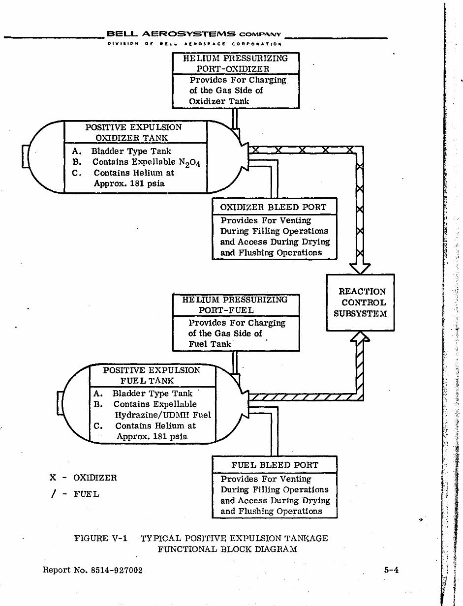
_________ SELL AEROSVSTEMS COMPA.NY _________ _
~
..
.
HELIUi\! PRESSURIZING PORT-OXIDIZER
Provides For Charging of the Gas Side of Oxidizer Tank
POSITIVE EXPULSION .......... , OXIDIZER TANK
" A. Bladder Type Tank x x x x
B. Contains Expellable N204 C. Contains Helium at '"
Approx. 181 psia
OXIDIZER BLEED PORT
Provides For Venting During Filling Operations and Access During Drying and Flushing Operations
HE LIUM PRESSURIZING PORT-FUEL
Provides For Charging of the Gas Side of Fuel Tank'
.
( POSITIVE EXPULSION "\ FUEL TANK
A. Bladder Type Tank' ..... LfL/LLLL
B. Contains Expellable
" Hydrazine/UDMH Fuel
l/ C. Contains Helium at Approx. 181 pSia
FUEL BLEED PORT
X - OXIDIZER Provides For Venting'
/ - FUEL During Filling Operations and Access During Drying and Flushing Operations
FIGURE V-1 TYPICAL POSITIVE EXPULSION TANKAGE FUNCTIONAL BLOCK DIAGRAM
Report No. 8514-927002
.
x
~
~
~
~
~
0 REACTION CONTROL
SUBSYSTEM
~ !:I.
II II ~
~ .;
5-4
"
;i
~
~':
.!
:!
" .' ,~
" 1 ~.\
~~ • ,I ~ .~ ~~
" ~ "
if' . :~ 'fi
j'~ .'" '~'
"1 i:: ',1 , "
. <
1 '. I
,~ :.
f ;
,
0
• . ~
. . ' ~
~ f ~
: I :.';'j
,':.1 , ,
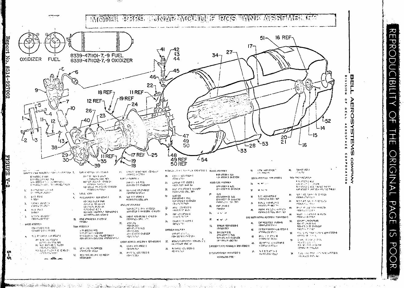
QI I 0\
.~""
1'-::~ ("''frJf~;!.:T' :;;.';Y'~ '7r'fj" ",' ~T7C"'F;":l'T; ?,;: -ro.'l'r": ":;·;.:nplI'P? r\'\"::I~ =n :1 M;" ,. ~k" "
l_~~ .. ~-=~:~:-~--'-.-~. ~~ ~~:("~\_!~~:_~'~~=~":.;:~_~~' C::~~_~ __ "~.::~~~.~~~ ~.\ I~~:~\ .. ,~ '_.~ ___ J 'In 'I'
"
iilli 51 16 REF\
11
8339-471101-7. -9 FUEL 8339-471102-7.-9 OXIDIZER
42 ~3 44 FUEL
r£. f;! / ~6 -J B 45
<:.t.~ II "'Ii"'. ------46 ~ f:::;~:::!.(\j~~,. _ ----- '\~~ 9-J\:::r!\~.;;;;; -....----- 2~~ . }::) U 18 REF II REF ~ ,
-5 .. \d;,It.-.. 7 12REF\ 1(7 19REF r' j ~ ~--,-l( .. " ~!-C 10 r 24 ' " ~~-, ~ ---:;"' .• ..:: : ~ r 26
... / ~...L - . 1,\ , . . y "" ""l..--·'{fli, ' ~ /' -." . . .~. Jl-J \.~'. \. "\ 12 \.c,\ 40'07 r23' .'~. ___ ~."I j~.. \; _.1::BJ.
1 .J'::$\:I \ --_ ( . ~". "-." " ~:.> . -c,:,'
J ~ Xv. :; [~ff' . '~,'" "~ .....-:-~ '-y/ ~.,.,.-'(t$~dl 71 J~"\ ."~~ . .'- Ir;;~ ,h,,-:;~-.' .. '\:~.,::"\,,,,:,:, ., ........... j > ~7;.;:--·~;;:'·'·'>· \\1 ',IIf \ ,~~ - -t-- "'11""' "":'i-\' ,/ , \. \ ... ~ '--- ~ -;::;:;.--..,....- ,
L \ :.1..---- { ~~~:·. __ M· --\\,;" .~--,- '\ {""~'. .:-.....:;: .. - '>d:" ".... .'
2 31 L ,,"-.... ~" ., .... "-', - [I _ \'2, "t Ci"'- ... : "..... ,,.' 1:. '." "'. . • 47 .
y " _ -. _ ., , t""-' I ~ ( "l\~.'-" .,. .~.",. Ir~· <19 I '\ 7 ~~~~r~~~t5 "i
48 50 , .'. .. " .~28 >C
5•
.;l1~,,- 30 y~ '-19 49 REF L54 39 . ''-18 50REF
UI .... :':·;-,·\j!l 'ib~,t.Tlo:-·l· ",1"': ~··"l'~·~·.' 7. ll,~! A','!!"\y "_'" !·!'t.vl
!tt' ~"r· ~j" ~(I\,~Y~ '-'~.1t;.i"'~"I~{1 1:~1
IlH \t 1 ~",~.1.' !~.1v~' , .. r~!','.'_" ";i !
I'. ':"','1' : .. :if{l'Alf~ ,1J<.:b'" ,~PI"!~ .... ::'f~ll
III UI .:> , ~'" i ~": """ ~~·II-!.'P~: I IIJ..Vl ""~H'81 '{ 15 tN MJ~ .l.:"tJ.!-'
" l.
,. ,.
lwwlll ,» 11111 ~~\'\·.\1\!L~·1 ':(1' ~:-\'--:lll··I·'J ' S'!'h!JlL:' l ~l'i\.
;o1,1l ,\: 'iter .... :: ~ I I j 11'!!.\L!,. ~":11 J
f·: ..... i{""'. ".1-1 t' . '-H ... ~'-', .~.:l·I"
1i'::T I.'i~~ t ,!UI'
",~~H~'{ ;.VV·', >:, L ',jJ 1\.::,'" ,,1!1.\·
~;.:, ,\\) 1 ~"H: •
\1 ',rt.:~: N,;'''' I' ,sr,;I'h$S ~,:;,t~'
V.lll1 ;.~S(!~!:\'
m~-c:,m··t Ittl
0,
~~'; ... m· ;t-~ \',II,:?fli:
'L.~ J,<,f:J,',r .. ~ ,.,.q-lIto/)~·t
Nl lL'1 .;'.'<:1(t:' .. ~ 1:'·~\·,·,5,\ru ~11
~t· '.~'f -\·;!'·--.!C'~ '1~~·trl ,q.'t·.;!'~ SIU!,
~i! !.tt.~ I .:.~ ~ ~r l~ "h.'l-' . ~:\". ':' .. ,1:U'
",- ~--:..
,
"
1>.
Io'tl SH,;! .,''','''l'~';: '~;;!Q'DI • ~t'\l"';'\ ~~!~~I
\,\[I'l .'~,'~I
I~! (j,,I.')~":'!l·· m~ ~i!:Al l
I'rl ::::,,1 fj"l~ Nl' ,':I: \;~ ,'t !.\~ 1, .. : .. ,1 I.D ,"d.'''' ,!'. ~l'.·~~ rl~ CJ5ui J:: t f.(!IHTt ': ;.s~n!l'1.~ tlJHn:lf~·t I,:j' Hltl'.", ~jj~·tl1~·)
,.v.l! fl)·.~,[C!(ii! 1 t];'!:}·ll l~ytl\"1
f:.. .. r ~~Srr.·flY "'~~·mI1H n~t
I),
!l.
".~ -!t'l'',!;·.' !-~ ltIll[~ ~,';';~~HI~' ~ ;~lll='!.tl>!rSIH\' ~m·m:'4 ~ O:luIUR I!":[!HD ...... '.;·
to"li.:J[ ~'''J:m;Cl tq~:' .. fS~ .. TIUI
Rl'~1 "lfi-!1I.;~-I'l.l;'.Ur;·
, m""l\JI.!1
~',,\t,', ~ ~)""I,'h T
~lrJ~''''I'~ rnl .!-'j'I·~n~,'!''i ('UHlIR
K
" H.~ " ... !~! 1.\~.'1'~rJ~ tST';lwns sni;l
l.uT ~~:l 4JI'l?H '~l"!~'d"S ~ntL:Ull
'1tM ll'~ ~\'~l',~lY
Ie.
17.
W"'~"::~:- t p·;t t? rt'J't1 ~m ~T!W 1 (:~I~IZHl' 12 ~Ia'~'
nWll1nhtl;I~11 '''!::t'1!)' IS1.\I!"I~~, STlt: ',"
WI.' ~!'.l oI[Fll" f.[l Sn)-J~':?1·S I,-It ITI;'I;',!t{t ~h !.'l~'1-1 '''It-l.tll t 1~ll~ \ 'ft \
l Y!tlf ill T.tI'J:; A~S~:.ti!1 Y ~n..e:1II1H
II.
:~,
(l!'.~.j ,.m mHl 1 qIHn"~t~·
t!t I'~ -.~. !:H !!WH 'riPI".iilI
'" " ~1 .
" ~I.
" ".
(~"·i ~i;~-.~Ilij.!~ I i !:Il~'-. ~i~'
\".tYl~ !.'r !711~ 1 ',!II,I::\t!I-' ,,,,'1-[1:0'
«',; ril.:Hl\l 1 '~h'U'[>' 'SIAI',,' ~') ,TtL }.:11
!:lo\{1~lii fH~ .:;t:I~·1 J'lH ojJQ .!1!1lI'.,H t\l~>llr? • ;'t •• _'\ '1~ IllP'
tlll-.( :j'I'~ll!lH ,411'1"',::' (l-d'
rAI' ~--'; I Jr~.!~ I ,1 Hl\ !ll·"IP·
rA,':,',' n ~1]1!)-1
H!lle,-'"
CIFfuSl!l A.~H·;RI ~
l1.
~
~!!t·Jr:'-, ,! ; ' .•• ~n'i-:1i"\J'l ""r'll" !If!.'.,',' ~ ':'~~l ",:! .. ~B~ Uk:/ I IA,lt';".ul.' [(111' It'
!!!S'lt",>; ·.':i"!ltW-1 IT(III \ .,: t
~iP·.!7!(,~·j H,H '.;lq ,mt'~:; ID_!~':rR
~ll!D 1::£1 ·~';:5fMOlY
,.
'" n.
1I.lH ·me;1 9 h:!L ~J'''·mO'lI·H Ol"lt'Ii'.,Q
n,u l:ihNm~~·n tLrt ~11'J·.~IIt-"-1~ t~ltll"(i! '''I,l.I'',,'~ -'{U )VI
r.e.p 1~,I"C '\rlO',1
',;, ' .. : ~I
, ") ',~~,'''.'! u~c.' . .\~~V,·,"l~ om !~:!l3H
" 11
~
" .n
..: ill"" •••
oC ".' "-f
TLr; IiH~·mnlH '~IA''''!'-'~ 'i1[1: ~n
fI,!. ... ·.i :;lINr,~lJ'1 t~ttom\,'" 'ilt.l :~,
t\'!.!ilr ,-') ~;:_'l .~, 1<")-:-1 lSiAL\'J\'5. "'llh -!ltl' ,'Ill
" cr.!, lMEl flmv~ .tS~r..'~H ~n'NJt'l'l"l
" ,.
~"",' c:'
SI'AUR E3;'hctOS!') mllO'.lI£1
D!I,U~f~ Ir~l
~lH-':llIP··l tll[l ~ll~·!n~\oo,·} r.-W!l[R 1,1. ! '.'I"l!\ t>:ltl-'I,'
~ IHUS£II F, ~l'\'; ~s~n.\E; y .i\H·.:1'ID',z·,
e':'tET "'~\H.'iitV ~'~HIUH~-)
'H"I\.[~S ':.rw·
... ~.
" ... :~
CAP "S~i.!t.~et ~ :'';'ffl'':S l'j,t:'_L'.,{'l'i. 'j".l' I'
fl'T!.1I. ~q,l.I'.I;;r ~.)/)-.:ro~·l tcr':'Lo,.,i,'l> 5T:'\.'
Ill.\..; 1, t'h-'I.I t~ I"',,· !'):, \T:H.
!U fl'!:"'; ~:,. ~ili1I.<;·] t ';:Al"lt~) \!,j;, j
\:,t r:~1 (':- :..-1 I.,HI~.,n~ ·,1'!l~1
16
... :';I"V~' ~rJ! , ' , .. ,~",
lot ... ';"1.' J.S·.i~'·rIV
AI
" ".
'" II.
" \)
"
~ 1'; .~"rn.: R,t ;en:; :'.' " .:"}III
~~'~!.:II;I·; It,t "l'\I.: ~.~'" !~~.t·IU!'1 If'I'll',~ II'~ '.!t·""'-al
"~1':',~1~ •• ~ ••. ~ 'Z·Flj)1 ,S';!.I" ! <\ ~ '0:, I
... ·lr.A·~ '.~." ':> 12'1'.:'. '<;'I~i~.,· '. ',I ••
ll'l;' !.' ;'.! ·,t t '~~i';,11
'~f~;' •• 0.', t.: I"
lil",T .'. ~''''·l'·~·l .~ A'J'iOl 1'i14t",t'.\<;NL'
l!:f·,I.··._','t'f I:'j.tTl !h'; C ....... ;0; ,;~t rm",:~l;. 11 (""lit!' 'I<.!."'-' ,.., ~lt' C', .: " .. ;!o' •• '". '1 .. •• tH1·:1'1:m,) 11t"-',"" .... !
,[ I'" . i~; '.' -} -:', .~;. :.'; ;>; F.;l' l!. -:~., :., ~~.""" 'H"',i I.~ ::'~ .. "I f:,,· •. ! '.~ ~".~ ., '.:', \',' .. -!r;~II-) ,It.,,',,·.I.1 'I~~, J,',
~ ID ~ rn ~ r ~ r o ) ~ m ~ ~ ~ 0 • Ul '" -< ~ Ul ~ -I : m ~ ~ n Ul 0
• n ~ 0 ~ ~ • :11 .. ;; ;; l z -<
'-~~-'-'~-'--"---- -- ............. ' .. -"---~{4;i-<;!:,~,_~-" :;;1{i,¥r .-:.? .~' .... ;,>.- • -\,';",d' ,,~ ,.',-.-'":..>- C', .-,' ~i
I F
l '.
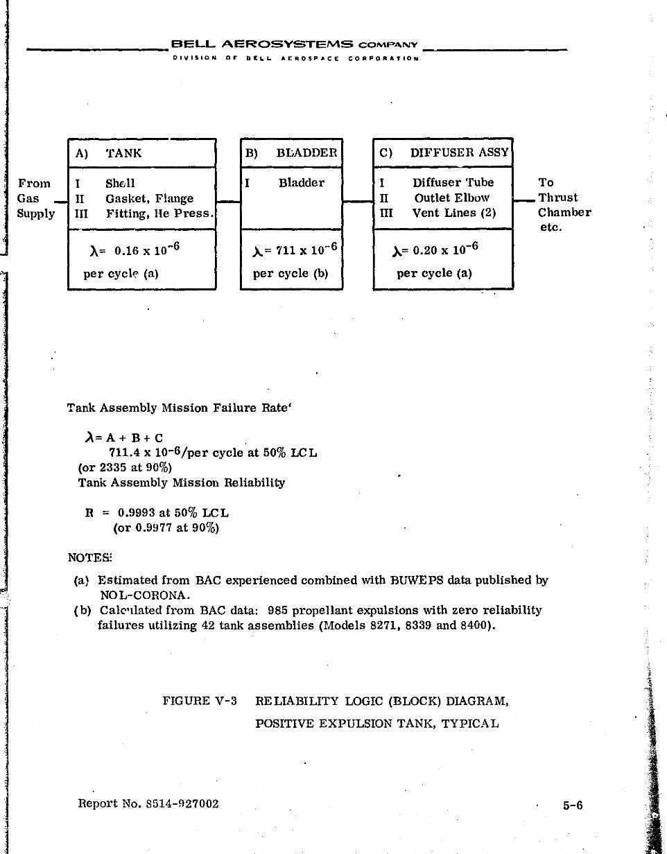
_________ BELL AEROSYSTEMS COMPANY __ ~ _______ _
From Gas Supply -
DIVISION OF' B[LL. AER05P"'CE CORPOIIIIATIOH
A) TANK B) BLADDER
I Shdl I Bladder II Gasket, Flange III Fitting, He Press.
r-).= 0.16 x 10⁻⁶ )...= 711 x 10-6
per cyck (a) per cycle (b)
Tank Assembly Mission Failure Rate'
~= A + B+ C . 711.4 x 10⁻⁶/per cycle at 50% LCL
(or 2335 at 90%) Tank Assembly Mission Reliability
R = 0.9993 at 50% LCL (or 0.9977 at 90%)
NOTES:
C) DIFFUSER ASSY
I Diffuser Tube II Outlet Elbow III Vent Lines (2)
)..= 0.20 x 10⁻⁶
per cycle (a)
I--
To Thrust Chamber etc.
(a} Estimated from BAC experienced combined with BUWEPS data published by NOL-CORONA.
(b) Calc"llated from BAC data: 985 propellant expulsions with zero reliability failures utilizing 42 tank assemblies (Models 8271, 8339 and 8400).
FIGURE V-3 RELIABILITY LOGIC (BLOCK) DIAGRAM,
POSITIVE EXPULSION TANK, TYPICAL
Report No. 8514-927002 5-6
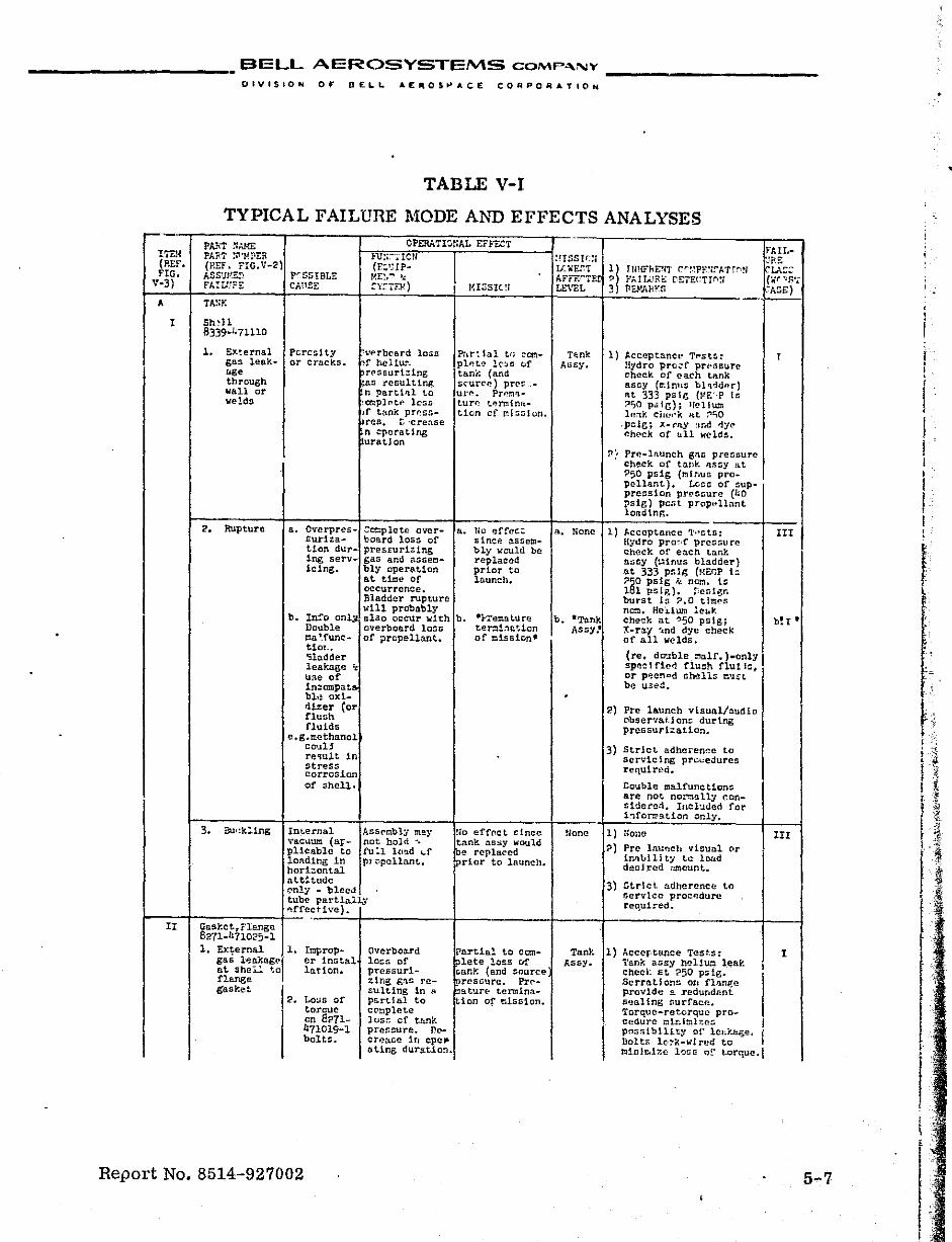
BELL AEROSYSTEMS CQMP .... "' ...
DIVISION OF DELL AEIIlOS~ACE CO~POR"TION
TABLE V-I
TYPICAL FAILURE MODE AND EFFECTS ANALYSES
I Sh~ll 8339-471110
1. EXternal glls lenkog. through wallar welds
2. Rupture
PeTcs1 ty or cracks.
.. 'erboard loss ,f hell\1%!, Tf?ssurt:!.ing
'an :rcnultln~ n partlrll to
.omplC'tf' loss Jf tank pT~S!ircn. r, 'crease n eperat1ng uratlon
8.. O'ferprcs- Ccoplete over£urlza~ board los~ of tion dur_ pres~urizins ing serv- gas and assemicing. bly oper$tion
Pnrtlal tr; eonpl .. t~ 10:'0 cf tank (and sC"uTC'e) pre~ .urr'. Pr.~t.l'lturf; tl'!lT.Iinf1.tion of ~lsslun.
a. flo effec: since assembly -..:culd be replaced prior to launch. a.t til':la Of
occurrenCe. Bladder rupture will probably
b. In~o onl~ also occur with b. -i-Temat.u TfJ ter!ll:l.!l~lon of tlisslon'
Double overboard Ions ma!fune- of propellant. tim., -;ladder leakage ;: U:le of 1ne omp.t. bl.~ oxi_ dizer (or flush fluids
e.g.methanol couB re'iult. in stress corrosion of shell.
Int.ernal ,"'.B.ClJU!!l (aFpl1cablc to lOA-ding 1n hori;:;ontal att~tudc
Assembly may not hold -, ru:l l(I'.ld I..f J'l1 ;:;pcllant.
f.'nly - bleed tube partially
I-_::_I-::--.--.--:-:--::_f-A_._frec ti ... e) .. II Gast.et,f1enge
8271-1171025-1 1. EXternal 1. Itlprop-
gas l~akngel er instal at shei.!. to lar.ion. flange gaSket
2. Loua of toreuc en 8271-471019-1 bolts.
Report No. 8514-927002
Ovcrbo3.rd lo~s of pressur1-2.1r~ g:'l.s rc:;ulting 1n .. pa.rtlal to cCltlplete los!: of thnk pressure. flee rf.!'Cl.se: 1 r. cpe l"nting durat1on~
Ilo effcc t f: f.nce tnnk nssy would ~~ repla~cd tprior to launch.
rartia! to co:n~~ete loss of Gank (and source
rC'ssttre. Pre-E;.tur& termination Of mlst;lon.
Tp..nk Assy.
a. tione
None
Tank Assy.
1) ~cceptnnce Tpsts: Hydro prc~f prefiGUre check of ea.ch tank assy (r::lnus bb<:ider) flt 333 pslg {ME"P 1.0 ?IjO p.ilG}; 1[('11\1::1 lWJ.k ciWI'j<; at :."''iO
·P::IC; x-ray and djlP chpck of t111 welds.
~! Pre-launch gns preSf'lure check at t::l.flk RoSSy at ?50 psig (mlTlus propellant). Less of suppression pressure (hO ~slg) pc .. t prop~llnnt londing.
1) ;'cc:cptnnce 'I"'sts: Hydro pro',f prcssu Te chock ot' each tank &:>cy (t.-anus bladder) at 333 pslg CHECP 1= ?5D psig k nOI:1. 15 181 pslg}. Per.ign burst 15 ?O tir.;t'5 nc:n. HeiiWll le(.k check at ~50 psiS; X-ray ~nd dye check of all welds.
(re. da~ble ~3lf.)_only !Ipezt rl~~ flush nUllc, or p~en<>d ahells t\'J,sL be u3ed.
2) Pre l&unch vlsual/nudio Clbservat.ions dur1ng prcssurlzation.
3) Strict adhc.ence to servicing pr~edures required.
Cauble malfunctions are not noro~tty r.onsl~ere:i. Incl'Jded for l~formati~n only.
1) flona
?) Prc launch visual or i~~ullity tc lCfid deoh'~d nmount..
3) 5trlcl adherence to ~crvlce proc~dure reqUired.
1) Accer·tance Tes~s: Tan~ assy heli~ leak checi: at ?50 ps1g. Sc rrn r.l on~ orl flange provide a redundant sealing surfacn. Torquc-retorquc procedure tllr.lmhc!> Pf1s~ib111ty of leJJ .. ..t:I.ge, Bolts lc·::-k-wJ red to I lllinlJ:liz£: l!:Jss 0[' t.orque.!
•
,
III
b! I •
III
! I
I I
5-7
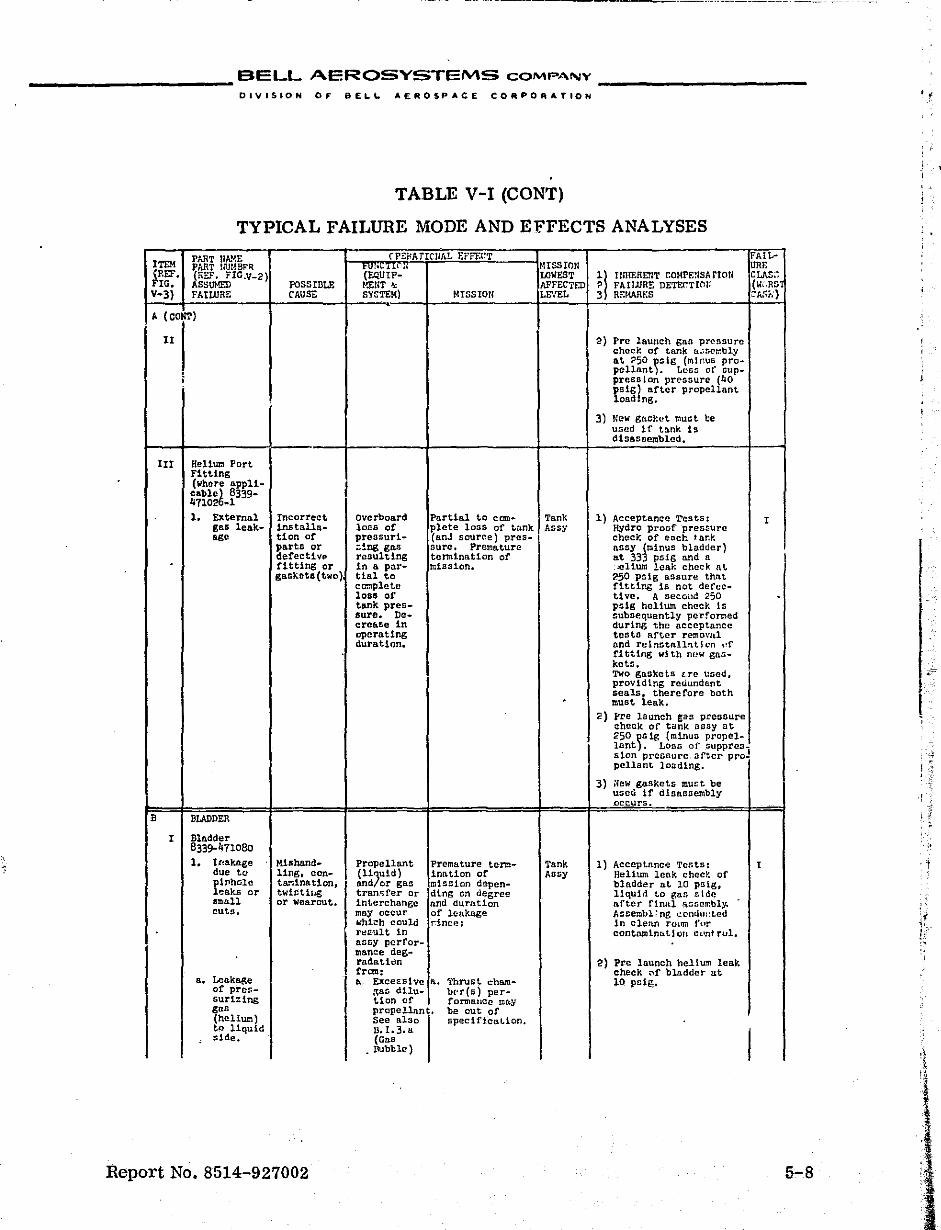
BELL AEROSYSTEMS COMPANY
------------------ DIVISION OF BEL.L. AEROSPACE CORPORATION . ;
TABLE V-I (CONT)
TYPICAL FAILURE MODE AND EFFECTS ANALYSES
PART tlA.~E (PEM TIC-IIAL EffF.I:T FAiL-ITEM PART IIlJIJ.SFR '(EQUip-' !USSIOrl URE (REF. (REF. FIG.V_2) LOWEST 11 ItnIERDIT r.OMrE!ISArtoU ClJ\Z;: FIG. ASSUHED pOSSIBLE r.!i:1'T &: AFfECTED ? F'ArUJRE DETEl.TWn eWeRS V-3) FAtWRE CAUSE. SYSTEM) I-ttSSIOn LEVEL 3 RF.WJU{S CAl'ir;)
A ( CONT)
II 2) Prc launch Sa:; prcsBurc check of tank o.~5ctr.bly
a.t ~50 )SlS (minus pro· pcllnot. Losl:: of flUp-
; presaton pressure (hO pS1sl after propellant load ug.
3) New gncket muot be uned 1 f t3.nk 15 dtsasncmblcd.
III Heltum Port Fitting (where appll-cab1;}; 8339-4710 -1 1. External Incorrect Overboard Partial to com- Tank 1) Acceptance ~e5ts: t
gaB leak- 1ru;tilla- 10ES of plete loss of tnnk Assy HYdro proof pressure age tion or pressurl- (anJ sauree) pres- cheek of eDC~ tank
parts or zing gn.s sure. Premature assy (minus bladder) defective result.lng tennination of at 333 psig and a . fitting or 1n a po.r- mission. .:ellum leak check at gask.~t8 (two) tinl to 250 psig assure thnt
co:nplete fitting is not derec-loss of tive. A secOild 250 tank pres- psig helium check Is flure. ne- subsequently performed cro&'Se in during the acceptance oporating tests after removal duration. and relnotnllntl on l,r
fi tUng wi th m~w gas-ket::. Two gaskets Lrc used. providtng reuundnnt seals. therefore both . must leak. •
2) ~re launch tas pressure check of tank nS$y at 250 ~G1g (minus propel-lant, Ltlns of" suppres_ sion prcosurc.aft.cr prol
I , pelIant loading,
3) ~ew gaSkets murt be use~ if dIsassembly occurs.
B BLADDER ;
I Blndder 8339-471080 ·i'
1. ttlakttge M!snand ... Prope.llant Premature tenn- Tank 1) ACCepL&nc~ Tests: t due to ling. eon- (l1;Uld) im1.Uon of ArJsy Helium leok checr. of pl'J"IhGlc tar;!nat1on, and or gas mission depen- bladder at 10 pstg. leaks or twiSt11;g tran.'ifer or ding on degree liqUId to gas r.lde IIthall or 'Wearout. int.erchango and duration after finlll a~!il!lI':bly, cuts. may occur of leakage Assembl ~ ng cC'nthll:ted
W'hi.:h could .r:ince: in clenn rmnn t'{1r
-j
r~/.u.tlt 1n contnmtnD.L1on cuot rol. nsny perfor_ mance deg .. radatitln 2) Pre launch helt~~ leak from: check "r bladder at
a. Lea.kage • EXcessiVe a. 'rhrust cham- 10 poig. of pres- ~a!i dUu- beds) per-sur1::ing tlon cf fonnance ma.y gus propeUn.nt. be cut of (helium) See 1'1.130 speciflcnt.lon, tp liqUid 13.I.3.a
I , side. (Gas • Ilubb1e)
Report No. 8514-927002 5-8
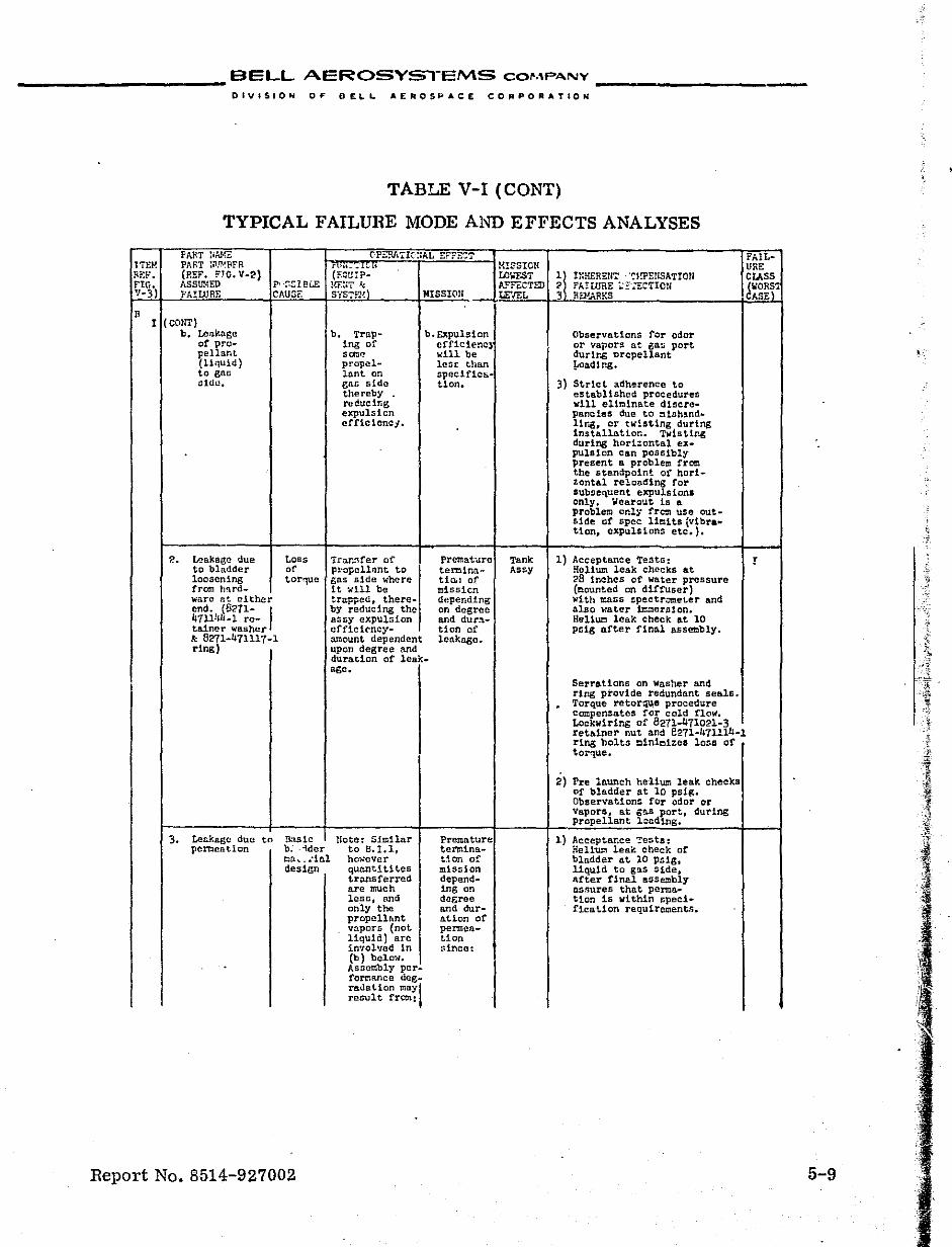
___________ BELL AEROSYS"l-EMS COMPANY __________ _
DIVISION OF BELL. AEROSPACE COFtPORATIOH
, TABLE V-I (CaNT)
TYPICAL FAILURE MODE AND EFFECTS ANALYSES
rAf\T hAJ{E rPE:::J,.'rIC-::A.L EFF'E':T FAIL-T'iEH PART :;T.o/FFR r 11_ ~:..~' .. M!SSICli UHE Rr:l-° • (REF. FrO. V-2) (EQUIP- Ul.r.sT ~l IlIH£RErr.~!·!l'E!l5ATIOIi ClASS FtG. ASSm~ED p, ·;;£:1 Bl.E !.ffi!'r .f,:; A.l:"fECT:lJ ? f'A.!WRE ::r';:.:C'rIOU (WOR51 V-3) r'AIUJRr: CAU5F. SYSTE1~) MISSINl LEVEL 3 REPJ..R~:S CASU
R I (callT)
b. Leakage b. Trap- b. EXpulsion Observations for odor of pro- lng of eff1clenc~ or Vapors at ga~ port pellanl ."'. will. be dUTlr~ ~ropellant (liquid) propcl- leor: than !ooadlng. to gnn Innt on speclflc~-old!!. ga& side ticn. 3) Strict ~dherence-to
thereby established procedures reducing vlll ell~lnate dlscre-
t,·:
expulsion pancies due to mlsh!nd. effie !cnci. 11r~, or twisting during
installation. T~lstlng during horl~ontal ex-
.
pulsion Can pOSsibly present a problem from the standpoint ot horl-tontAl reloading for SUbsequent expulsions only. Wearout 1s A problem only frc:n use out-Side of spec- l1cHs (vIbr .... tion, expulsions etc.).
~. lP-akaBc due tOBS Tra.n~feT of Premature Tank 1) Acceptance Test~: r to bladder of pl>opellant to temina- Assy Helium leak cheeks At loosening tor,uc gas Bide where tic,l of 28 inches of water pressure from hard_ it wIll be mlssicn (mounted on diffuser) ware nt either trapped, there- depending with ~aSS spectrometer and end. (8271- I by reducing the on degree also water ~ernion. 411141l-l re- a:iIiy expulsion and dura- Helium leak check At 10 tainer washer efficl('ncy- tion of psig after final assembly. k 8271-471117-1 amount dependent lenknge. ring) upon degree and
duration of leak. age.
Serrations on washer and ring provide redundant seals. . Torque retor:l~e procedure compensa.tes for cold flow. Lockwlring of 8271-471021-3 retainer nut and e271-Jqll14-1 rIng bolts ~lnlmlzel loss of torque.
2) Pre launch helium leak cheeks of bladder at 10 psig. Observations for odor or Vapors.J at ga.s port, during propellant l~cd1ng.
3. Leakage due to Basic note: Similar Premature 1) Acceptance Tests: pementlon b. ·ider to B.l.l, tel'Jl\ina- Helium leak check of
mo.~_.·inl ho ..... ever t.icn of bladder at 10 psIS, design quantlUtes mission liquid to gas Side,
transferred depend- after final assembly are much ing on llSmlreS that perma. .. lesfl, and c!agree tion is within spec!-only the and dur- ficat.lon requirements. propellant ation of v~por~ (not pennen-liquid) are tion involved In since! (b) belo ...... Assembly pcr-fomance deg_ radation maYl result fro:n:
Report No. 8514-927002 5-9
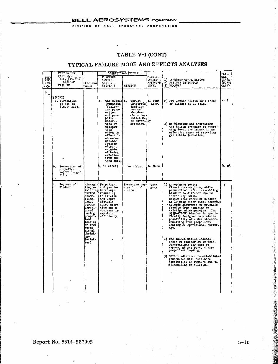
___________ BELL AEROSYSTEMS COMPANY
OIVISION CF BELL AEROSPACE CORPORATION
• TABLE V-I (CaNT)
TYPICAL FAILURE MODE AND EFFECTS ANALYSES .
PART U'JMnER OPERATIONAL r.rrtxT FAIL-
~~ PhRT tllJlF. i'1.!!iC,!,;'OII HISSlf'!U uru; (REY. FIG. V-2) (EQ'ITP~ tllilF'.."iT ;! IN~RflIT CClMPElISATION ClASS
t:tr.. MlSUMED PrZntllLF. MEnT k Ar·FECTF.1l FAtWRE DE'rtCTIOlI (WORST V-3) l"AfUlRE rAUSE SYSTEM ) rUSSICIlI LEVEL Re-'ARf:S CASE)
n I
3 (CONT) ". Permea.t.1on a. Gall bubble •• Thrust a. Tank ?) Pre launch hell~ leak check a. I
of gas t::> fonnlltion Chnmbcr(nj lossy. of bla~der at 10 psig. liquid side. (follo..,- ignItion I
ing perm .. run and eation shutdown amS pro- character-pellant !sUeG may saturn ... be adversely ticn by affected. 3) Rc-bleed~ng and increasing dlsso1u ... the helium pressure to opera-tlon) ting level pre launch 15 a~ whl('h In effective means of retarding effect 1s S&& bubble to~at1on. an unde-sirable foreisn clement capable of being expelled
- frem the tank 8S0y.
b. Pennention of ~. No er1'ec~ b. No erfect b. None b. ftA propellant. vapors t.o gns sidt..
4. Rupture of Mlshand Propellnnt Premature ter_ Tank 1) Acceptance Tests: ! Bladder ling or ami gas tn- mlnation of Assy Visual observationa, while
twlstine terchange mission. pressurized, after tlssembl1l.g during resulting bladder to d1f1'uGer s}'."ul,d assem .. In erratic de,teet any t."ist. . bUng. and unpre- Helium leak. cheek of bladder Undue dlctab1e at 10 pSig after final aSF>cmbly streG!': nssy. opera- ~ affords assurance of prObable exper1- tion and a f~eedom from handling or
I anced decrease in twistIng dl~crepancies. The during expulsion 8339-471080 bladder is spec i_ prope~- efficiency. rically designed to mlnici%e lanl possibility of undue stresses londing reSUlting from prope1l~t :ar from loading or operational shrink-loprrn.- age. tiona! hrink.~
~~lnk- . 2) PIe launch helIum leakage eG.) cheek of bladder at 10 psig.
Observatlons fo~ odor or va~ors. at 6SS port, dur1ng propellant loading.
3) Strict adherence to established procedures wIll eliminate posslb.111ty of rupture due: miShandling or twisting.
to
Report No. 8514-927002 5-10
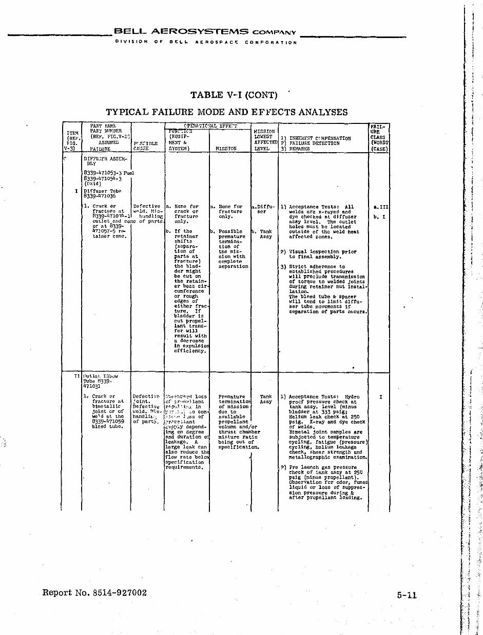
___________ BELL AEROSYSTEMS COMP"N'r'
DIVISION OF DELL "EROSP"C~ CO~POR"TION
TABLE V-I (CONT)
TYPICAL FAILURE MODE AND EFFECTS ANALYSES PAR'!' rWfr.. ('PE!{ATIC'~;A.L !::FFE·.-T FAlt-
I PART IM'BEn f-"l' ~~Il:~~,~IIr'1~::~::::f",iF.='T::':;"=="--t lussrOIl URE (~~. (REr'. r'IG.V-2) (f.QUip~· LDf:EGT ~) IrIHF.RFNT C~'MpgN5ATrOn C(LASS f.'lO. ASSUMED prS~InLE MEUT &. AFFECTED .,.) F!\IWRE DETECTiCN wonST
rV~-~3~)-1~~P~A~ILU~R~E~ ____ rC~A~~~3~E~ __ ~ S_YcS~T_EM~) ____ -t~M~I~s~sr~0~1I ____ t-LE_'_\~_'_L __ ~3~)_'_E_'~ __ R_'~ ________________ -1~(~C~A~SE~)'1
DIFf'I.~rR ASC£M- I r RLy
8339-471053-3 Fuel 8339-"7105"-3 (OY.ld)
1 Diffuser TUbe 8339-471036
Defective n. w .... ld. '.:1 &
h:lnclling
1. Crnck or fracture nt H339·lj 'llO,Ii-l out.let. cud cone or nt. 8339-41105'(-5 riO.
talner eon!!.
none for craCl'; or frncture only.
Tl Putlet F.lbuw Tube 11339-471031
L Crack or fracture at binlctnlHc joint or of weld at the 8339-4'11059 bleed tube.
of pn.rtn
b. If the rctainer shffts (separo.tion of parts at rracture) the bladder mIght be cut on the retainer boss cir cwnference or rough edges of either frac ture. If bladd~r is cut propellant. t.ralH>fer will result with a dccrcage in expubio efficiency.
Dcfcctb(; P"""'-i,'~'!;''\,~rJ loss jOint.. 11(;( .,r,,«'.,.'i lant Dgfectho: E-t't1\<.~ '-l),,), in w(!;ld. !Hs";i'!]" :\ .. : '~o cern handlll<~ },; ;i;',,~ J ;ss of of part?>, ,J:\)'.~'I:~l~ant
'~~~:t{.':y depending on degree and duration 01 leak!:t.ge. A lnrge lenk can also rl~duc(! th flo"tt rate belo spec 1ftcn.tion rCl1.uirernents.
Report No. 8514-927002
a. Uone for fracture only.
b. POBslblc premature tenn.1na ... tion of the mt,snion with complcte separation
!',Dirfu-ser
1'" Tank Asay
Premature Tank termlnatl0 Assy of mission dUI} to a.va.ilable propellant volutm and/or thrust chamber mixture Tatio being out of specification.
1} Acceptance Teats: All welda aTc x-rayed and d7e checked at diffuser QSsy level. Th~ outlet holes must be loca.ted outside of tho weld he&t affected zones.
?) Vlsual inspection pr1.o!' to final &Gsembly.
3) Strict adherence to established procedures w1ll preclude transt:lss10n of torque to welded Joints during retainer nut installaUon. The bleed tube & spacer will tend to limit diffuser tube movcmen~S if scpara~lon of parts occurs.
1) Acceptance Tests: Hydro pro.;f pressure check at tank as By. level (minus bladder at 333 psiS; Helium leak check at 250 psig. X-ray and dye check of Welds. Bimetal joint samples are subjected to temperature cycllng, fatigue (pressure) cyclIng, helium le~kage Check, shear strength nnd tlIetnllographlc examination.
?) Pre launch gas pressure check of tank a5sy at 250 psig (minus propellant). Observation fer odor, fumes liqUid or loss of SuppreSalan pressure during & after propellant 10adlng.
•• IIl
b. I
I
5-11
i
:-.
1 j
I
I ,
1 I
i i 1 "
, 1 j -~
i
1 ! , , 1 ,
..j I
:1 ~
. " ,J '1 • , ,
I ' ·1 " ,
" ,
i ! I
.-J; "
j
j "1
'{ .. : ,
"~
~j,
Jj ~-1
~
.J;
.:'t,
~
:,
D
t -# ~
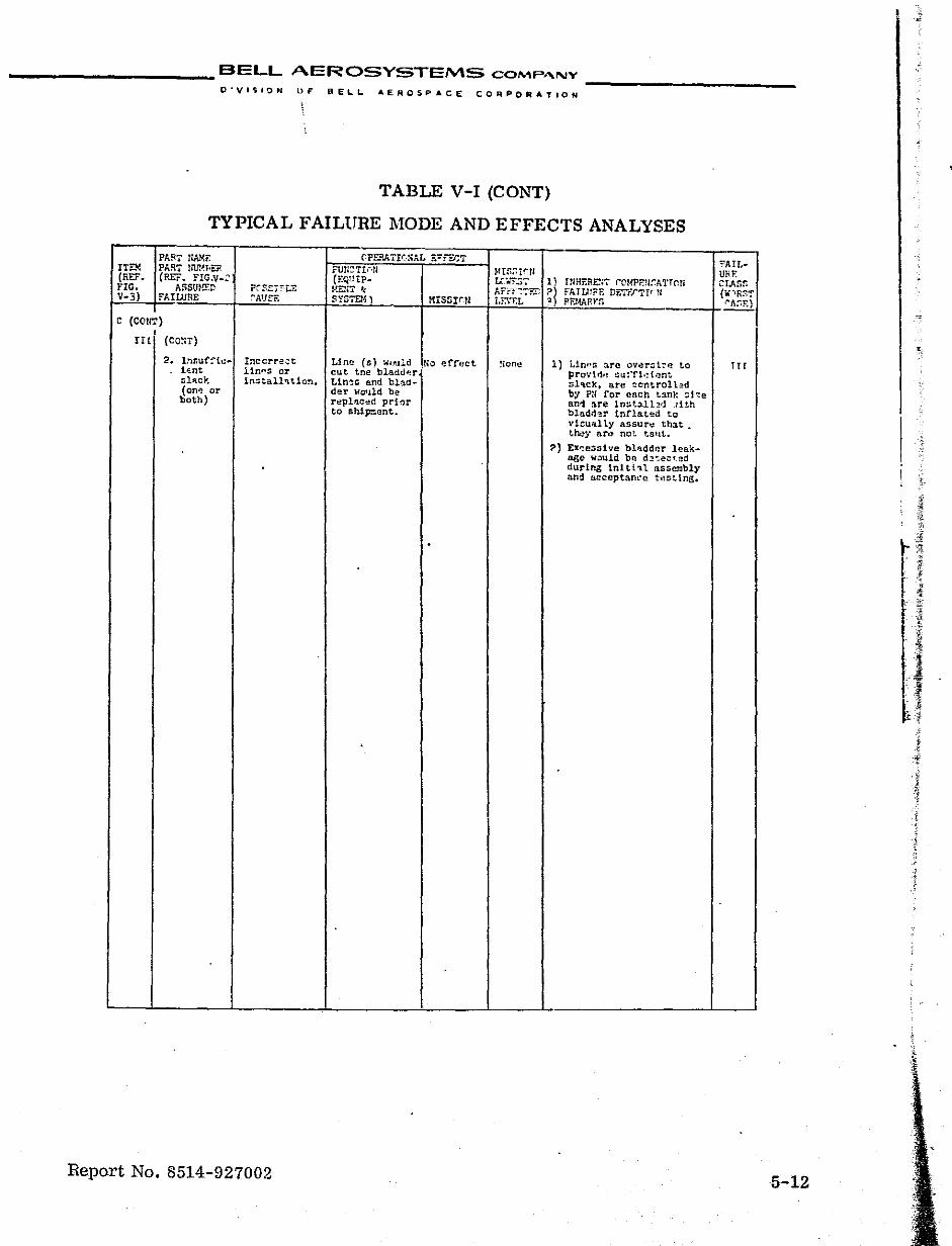
___________ BELL AEROSYSTEMS COMP,,"NY __________ _
O'VI'iIQN OF PELL AEROSPACE CO~PORATION
TABLE V-I (CONT)
TYPICAL FAILURE MODE AND EFFECTS ANALYSES
PART flAME flPE?ATrq'AL E";'r ECT FAIL-ITEM PART tM~FlER FUfj::;'t!r.!I ~ltfi:;r~U URr. (REt. (REF. FIG.V_'; (EQlItP- UW.5T 1) mHERE:7 rCMPE?lf.A'l'TC'1l1 crJ..f,f, FIG. ASSUHED P('~'::FLE MEii'l" '.: AFrF-:7iID ~l Ft..TW?E DETF'J"Tt"1I C ....... R!O'f V-3) FAIWRE r'A'H:-E S~'STEM ) MISSlr·n LF.\T.L PF'J-tA,iH'S ~
C (COllT) I
Il( (CO!n)
2. I:uiuf!'ic .. Inccrre;::t Lint! (5) .. wuld rio effect !Iorl\,! 1) Lin"::; 3.TC overtot:,!,! to rrr i"lnt 11n"s or cut tne bladdl!T pro·;lr1.! :l1J!'fl·:t.~nt ~l'lcJt; In.::; tall'l t 10n. Un!!:s and blad- :;l'lck. are controll~d (OM or der wO'lld be by P:: for each t:mk ::l-::e both) r~plllcl!d prior ani ore Innbll:!d rith
to ship:::ant. blndrl~r Infla.t~d to vl~u~lly aSBUT\,! th:lt. Lh.!y nTo) no!:. taltt..
?) EX~e~slve blllddeT leak-age w;)uld bl'! d:!,:ecu~d during tnlti~l assembly en~ l1cceptam"!!; test lns. I
.
,
Report No. 8514-927002 5-12
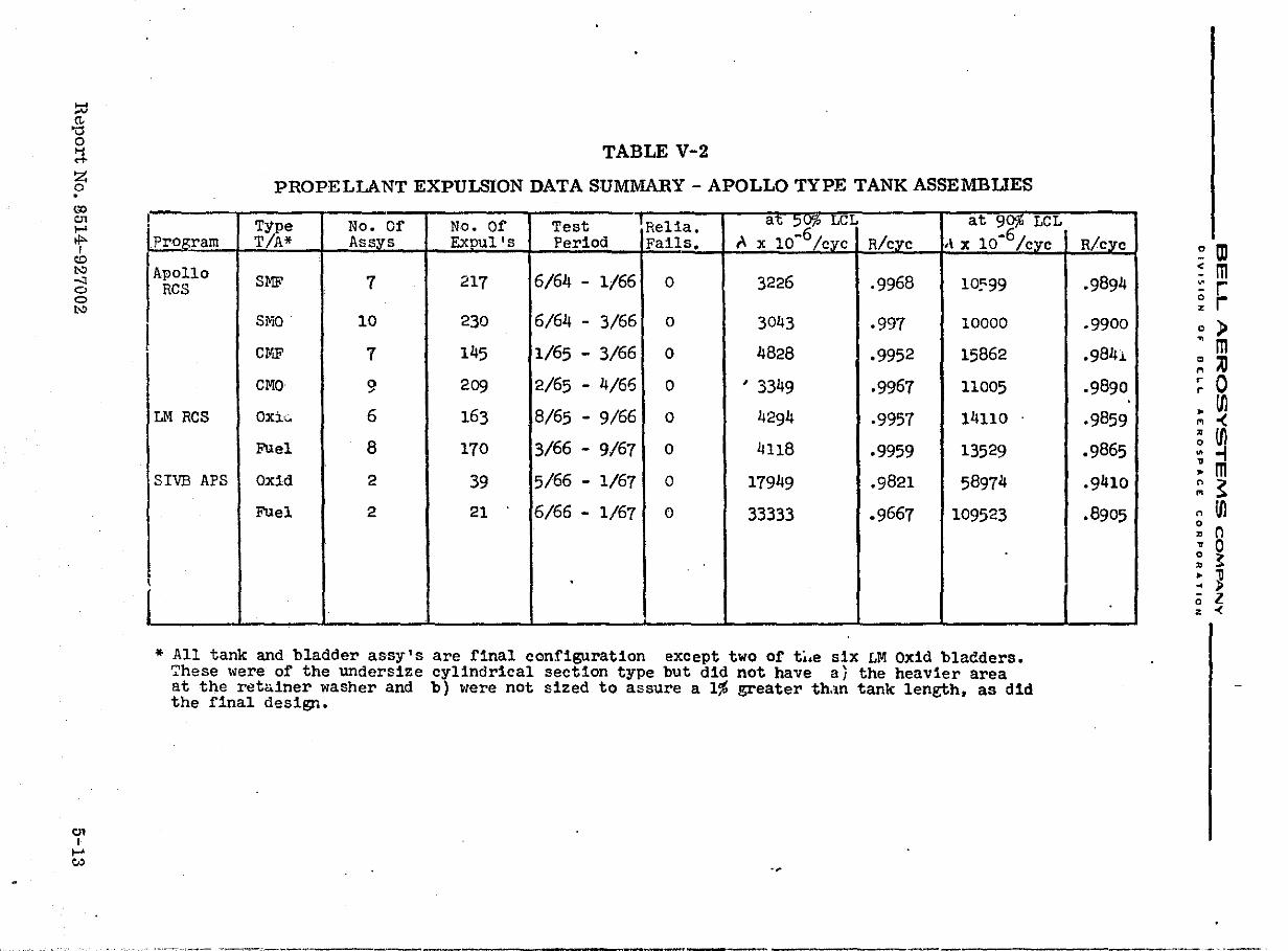
::0 (""
"0 o ~ Z o . (lO tTl ~ tl>I
Cl:)
t>:l -'I o o t>:l
tTl I ~ v:>
!
I
i
TABLE V-2
PROPELLANT EXPULSION DATA SUMMARY - APOLLO TYPE TANK ASSEMBLIES
T1pe No. Of No. Of Test 'Rel1a. a"t :;,~ LCL at 9~ LCL Program T/A* Assys Expul's Period Fails. A x 10-6/ CYC R/cl"c ,\ x 1O-6/cyC
Apollo SM£" 7 217 6/64 - 1/66 0 3226 .9968 10~99 RCS
SMO 10 230 6/64 - 3/66 0 3043 .997 10000
CIIIF' 7 145 1/65 - 3/66 0 4828 .9952 15862
CMO 9 209 2/65 - 4/66 0 ' 3349 .9967 11005
LM Res Oxi" 6 163 8/65 - 9/66 0 4294 .9957 14110 .
FUel 8 170 3/66 - 9/67 0 4118 .9959 13529
SIVE APS Oxid 2 39 5/66 - 1/67 0 17949 .9821 5897~
Fuel 2 21 6/66 - 1/67 0 33333 .9667 109523
.
* All tank and bladder assy's are final configuration except two of t~.e six LM Oxid bladders. ~hese were of the undersize cylindrical section type but did not have a) the heavier area at the retainer waSher and b) ~Iere not sized to assure a 1~ greater th.m tank length, as d1d the final design.
-~
R/cyC ~ m
.9894 ~ m ::: r ~ r
.9900. ,
.9841 I
.9890 I ,
.9859
o ) ~ m ~ ,;) ~ 0 ~ Ul '" -<
.9865
.9410
~ Ul .. -i ! m ~ ~
.8905 n Ul 0 • n ~ 0 ~ ~ ~ 11 .. p o l z <
______ -, ______ ~------.. ----~~~~r '<.~ T.'<'..,~: ...... ~:;..,,;·~~;.,;...;f';w,>rii~:m;.:-;,;;,-;;-~;;,;:';;::;-:> ,-;--.-,;;;-~__::::7.,;:._;:::_...;". """';:.f..Md;f"·2.it.",:::,,,;;~~~~,;;',ifr'~(\';F';~:;:J:.<-iJ.ri";::"">-',r~ :;~~-.·,;...~,r>;lf~J;~;,,,-,,,'r,' .'." #'. ,<,:t..r :_,' ,: .•. ',.'
------------- _ .. __ .
~;., ,- ¥ ~
,
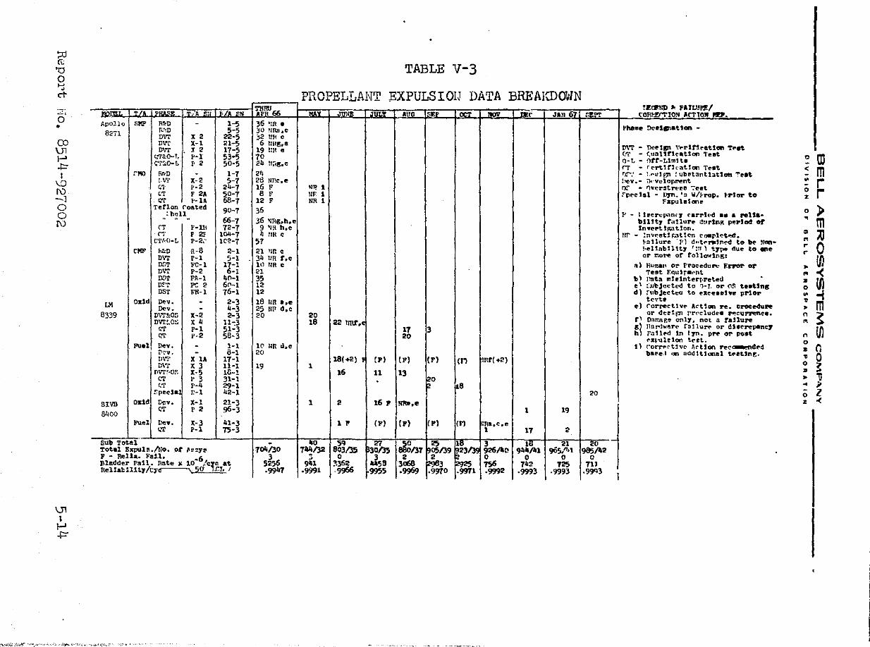
::0 (t;
'0 0 ~ ., ci"
--- -----.;..:,
0 Apollo "I'll' R~D • r,.··.D 8::71 mrr X 2 CO Dvr X-I \Jl mrr X 2 l-' c;'J'ltC-TI P-l
~ I;'r:-':()..L I' 2
I eM rlfrD I,V!' X-2 \0
I\) 41 .-2 'T F 2.
-1 "" f'-lA 0 Tetlon roated 0 : hell
" " " 1\) rr F-ll{ rr F2f
C'l .. ~O"'L p~2~'
rl'll' Me R-8 OW P-1 Dr.T '!-'C-l D\"r p-2 roT FA-l Dr-r PC2 OST FR-1
LM u~",ul DP.v. Dov.
8339 D\O'T!:OS x-a
\Jl I l-' ~
SIVB 81100
.• ·~4~·~ "~.",,.,.>--~ ,:._",'~'("- -'~''l'".,
I onol
X 4 P-1 V-2
XU X 3 X-5 V 3 p-4 r.-l
L'~v. X-I CT P 2
X-3 P-1
_-----101'U'IlU I
1-5 36 ~IR e 5-5 30 URB,e
22-5 ;2 fm c 21-5 6 nU~.1!I 17-5 19 liN e 53-5 10 50-5 24 t1;"18,e
1-1 21, 5-1 28 !.Jne.e
24-1 16 F 50-7 B F 68-1 12 F 90-1 36 68-1 36 ~ng,h,e 72-1 9 ·m h.e
10li-1 ~ nR c lC~-7 51
2-1 21 fIR C 5-1 3~ UR r,e
17-1 III TlR e 6"1 21
40-1 35 60-1 12 16-1 12
2-3 18 UR .,e 4-3 25 NIt d,e 2-3 20
1l~3 51-3 58-3
1-1 1(1 liR !i,e 8-1 20
11-1 11-1 19 18-~ 31-1 29-1 42-1 21-3 96-3
41-3 15-3
1~130 3
5256 .9947
TABLE V-3
PROPELLANT EXPULSIOIJ DATA BREAKDOV1N
Phillie !>clfs.,aUan ...
m'T ... DcUDl \'t"rlnratian Tf"et I ('I.' ... (,tlanrleaUon Teat OwL ... nrr-Ll~!t. c ID rr ... r{"1"'tlth·at.!on Teat < m f)f';' ... :,,.ul f1' : ub~tant13ttOft '!'ut l~v.- r}!-Yetopr!'lPnt M r UP. t Of .. r'lvr.r~t.rt'l!e '7eet 0 r llF 1 fpt"c'st ... urn. '3 ~/~rop. trior to % NR 1 Fapul.looe
0 ) }-' - I lecrer. .. ·mrr carrt(·d ••• relS&. bUtt, tutlurlf' ~ttr1nK p"Plad or ~ m InyeptlRatlon.
lW ... lnveetl~~tl~n eoerl{"t~. " ;0 '" }:ll1ure 'TIl t1.·te,.tnoM! to tl'e Nftn- .. 0 "l!UnbUU, 'lIT) t,.~ due to .. eo r-or r.o~ of rollawlngJ
fJl a) Human or fl"OC'edu .... · EI'I'O'r' or ~
Teet F.quJr.t~nt. '" 0( bl l)ata IIIblntt!rr.reted •
~ e' ::JJbJcctl.'d to 1-1. or (l~ te.Uns 0 d) [\lbJeett:O to ellee .. he prior ..
tCl!t. ~ e) rorret'tlvt" At'tign ft. ICroee4ure m •
20 or deel~~ rr~t'lud~. ~t'g~ee. n ~ 18 22 lmt, r' Da~hge on11. not a raJ lure '" 17 3 8~ l1ul""hrler(" ffll1urt" or dJlerepane,. Ul 20 h fallf'd In 17ft. prr or po.t n
f'll~'ulelon te~t. 0 t' ('crrf'('t1v(" ArUen ree~4l1!'d • r. baee·1 un Dod 1tlooel tf'.Unt. ~ 0 18(+2) (p) lp) IF) en mr(+2} 0 1 • ~ 16 11 13 • " 0 r .. ;.
20 0 l 1 2 16 P NII8.e % 0(
1 19
1 P
Ii - :;, . s'- ,