Embed Size (px)
Citation preview
MEDICAL NOW No.76 (2014.8)
R/F
Applications and Present Issues of Tomosynthesis in Spine Surgery
87th Annual Meeting of the Japanese Orthopaedic
Association—Evening Seminar 4
Yoshiharu Kato, M.D., Ph.D.
Professor and Chairman
Department of Orthopaedic Surgery
Tokyo Women's Medical University
Yoshiharu Kato
For the 87th Annual Meeting of the Japanese
Orthopaedic Association (from May 22 to 25,
2014) Shimadzu and the association jointly held
the evening seminar on the 23rd. We invited
Shoichi Ichimura, M.D. (Professor, Department of
Orthopaedic Surgery, Kyorin University School
of Medicine) to chair the seminar and
Yoshiharu Kato, M.D., Ph.D. (Professor and
Chairman of the Department of Orthopaedic
Surgery at the Tokyo Women's Medical University)
to give a presentation entitled Applications and
Present Issues of Tomosynthesis in Spine
Surgery. The following is a description of what
was discussed at the seminar.
1. Introduction
Today I will talk about applications and present
issues of tomosynthesis in spine surgery. Actually,
Shimadzu has offered tomosynthesis ("TS" below)
systems since about 2003 and reportedly has sold
over 400 units so far. This system was initially
designed as an X-ray fluoroscopy system for
gastrointestinal examinations. Therefore, it is most
commonly used for upper gastrointestinal tract
X-ray examinations. Most medical universities in
Japan have one, so when you return to work you
may be surprised to discover that your radiology
department already has a Shimadzu tomosynthesis
system. However, orthopedic surgeons started
becoming aware of these systems only in about
2010, so there may still be many orthopedic
surgeons that are unfamiliar with tomosynthesis.
Today I will first compare TS to plain radiography
and CT in terms of performing spine surgery to
treat cervical and lumbar spine disorders (Fig. 1).
Specifically, I will refer to disorders such as OPLL
and RA. The most valuable use for TS is evaluating
images involving spinal instrumentations. It is
especially useful for evaluating bone fusion after
PLF or PLIF or screw loosening by using the
T-smart, which specifically eliminates metal artifacts.
In addition, I will talk about both TS and SLOT
radiography starting to be used in conjunction for
sagittal alignment applications. This is extremely
useful for measuring the angle of the pelvis and spine.
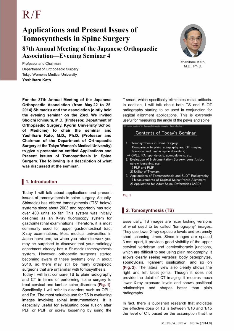
87th Annual Meeting of the Japanese Orthopaedic Association—Evening Seminar 4
1. Tomosynthesis in Spine Surgery• Comparison to plain radiography and CT imaging (cervical and lumbar spine disorders)
⇒ OPLL, RA, spondylosis, spondylolysis, etc.2. Evaluation of Instrumentation Surgery: bone fusion,
screw loosening, etc.1) PLF and PLIF2) Utility of T-smart
3. Applications of Tomosynthesis and SLOT Radiography1) Measurements of Sagittal Spino-Pelvic Alignment2) Application for Adult Spinal Deformities (ASD)
Contents of Today's Seminar
Fig. 1
2. Tomosynthesis (TS)
Essentially, TS images are nicer looking versions
of what used to be called "tomography" images.
They use lower X-ray exposure levels and extremely
short scanning times. Since images are spaced
3 mm apart, it provides good visibility of the upper
cervical vertebrae and cervicothoracic junctions,
which are difficult to see using plain radiography. It
allows clearly seeing vertebral body osteophytes,
spondylosis, ligament ossification, and so on
(Fig. 2). The lateral view also clearly shows the
right and left facet joints. Though it does not
provide the detail of CT imaging, it requires much
lower X-ray exposure levels and shows positional
relationships and shapes better than plain
radiography.
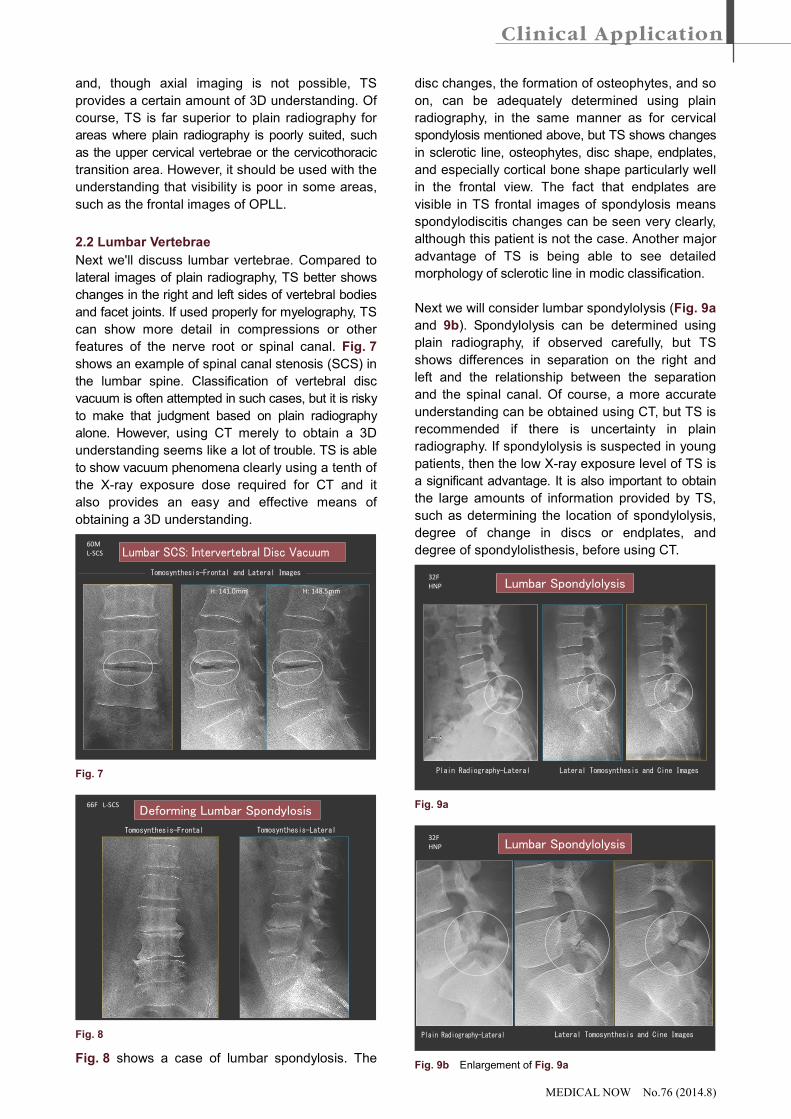
In fact, there is published research that indicates
the effective dose of TS is between 1/10 and 1/15
the level of CT, based on the assumption that the
MEDICAL NOW No.76 (2014.8)
thoracic spine is comparable to the chest and
the lumbar spine is comparable to the abdomen
(Fig. 3). Since reducing X-ray exposure levels is
very important, it is also extremely important to
understand what can be accomplished with TS so
that the CT usage rate can be minimized.
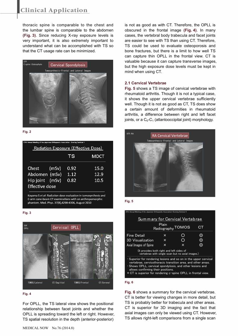
57F
C-spine Osteophyte
Tomosynthesis—Frontal and Lateral Images
Cervical Spondylosis
Fig. 2
Fig. 3
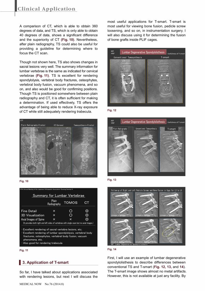
59F
OPLL Cervical OPLL
CT/Sagittal CT/CoronalTOMOS/Lateral TOMOS/Frontal
H H
F F
Fig. 4
For OPLL, the TS lateral view shows the positional
relationship between facet joints and whether the
OPLL is spreading toward the left or right. However,
TS spatial resolution in the depth (anterior-posterior)
is not as good as with CT. Therefore, the OPLL is
obscured in the frontal image (Fig. 4). In many
cases, the vertebral body trabecula and facet joints
are easier to see with TS than using CT. Therefore,
TS could be used to evaluate osteoporosis and
bone fractures, but there is a limit to how well TS
can capture thin OPLL in the frontal view. CT is
valuable because it can capture transverse images,
but the high exposure dose levels must be kept in
mind when using CT.
2.1 Cervical Vertebrae
Fig. 5 shows a TS image of cervical vertebrae with
rheumatoid arthritis. Though it is not a typical case,
it shows the upper cervical vertebrae sufficiently
well. Though it is not as good as CT, TS does show
a certain amount of deformities in rheumatoid
arthritis, a difference between right and left facet
joints, or a C0-C1 (atlantooccipital joint) morphology.
47F: RA
Tomosynthesis—Frontal and Lateral Images
RA Cervical Vertebrae
Fig. 5
87th Annual Meeting of the Japanese Orthopaedic Association—Evening Seminar 4
PlainRadiographyTOMOS CT
Fine Detail × ○ ◎3D Visualization × ○ ◎Axial Images of Spine × × ◎
(It provides both right and left sides of vertebrae with single scan but no axial images.)
Sum m ary for Cervical Vertebrae
• Superior for rendering lesions and so on in the upper cervical vertebrae, cervicothoracic transition area, and other areas.• Shows OPLL, cervical spondylosis, and other lesions and allows confirming their positions.* CT is superior for rendering c-spine OPLL in frontal view.
Fig. 6
Fig. 6 shows a summary for the cervical vertebrae.
CT is better for viewing changes in more detail, but
TS is probably better for trabecula and other areas.
CT is superior for 3D imaging and the fact that
axial images can only be viewed using CT. However,
TS allows right-left comparisons from a single scan
MEDICAL NOW No.76 (2014.8)
and, though axial imaging is not possible, TS
provides a certain amount of 3D understanding. Of
course, TS is far superior to plain radiography for
areas where plain radiography is poorly suited, such
as the upper cervical vertebrae or the cervicothoracic
transition area. However, it should be used with the
understanding that visibility is poor in some areas,
such as the frontal images of OPLL.
2.2 Lumbar Vertebrae
Next we'll discuss lumbar vertebrae. Compared to
lateral images of plain radiography, TS better shows
changes in the right and left sides of vertebral bodies
and facet joints. If used properly for myelography, TS
can show more detail in compressions or other
features of the nerve root or spinal canal. Fig. 7
shows an example of spinal canal stenosis (SCS) in
the lumbar spine. Classification of vertebral disc
vacuum is often attempted in such cases, but it is risky
to make that judgment based on plain radiography
alone. However, using CT merely to obtain a 3D
understanding seems like a lot of trouble. TS is able
to show vacuum phenomena clearly using a tenth of
the X-ray exposure dose required for CT and it
also provides an easy and effective means of
obtaining a 3D understanding.
60M
L-SCS
H: 141.0mm H: 148.5mm
Tomosynthesis—Frontal and Lateral Images
Lumbar SCS: Intervertebral Disc Vacuum
Fig. 7
66F L-SCS
Tomosynthesis—LateralTomosynthesis—Frontal
Deforming Lumbar Spondylosis
Fig. 8
Fig. 8 shows a case of lumbar spondylosis. The
disc changes, the formation of osteophytes, and so
on, can be adequately determined using plain
radiography, in the same manner as for cervical
spondylosis mentioned above, but TS shows changes
in sclerotic line, osteophytes, disc shape, endplates,
and especially cortical bone shape particularly well
in the frontal view. The fact that endplates are
visible in TS frontal images of spondylosis means
spondylodiscitis changes can be seen very clearly,
although this patient is not the case. Another major
advantage of TS is being able to see detailed
morphology of sclerotic line in modic classification.
Next we will consider lumbar spondylolysis (Fig. 9a
and 9b). Spondylolysis can be determined using
plain radiography, if observed carefully, but TS
shows differences in separation on the right and
left and the relationship between the separation
and the spinal canal. Of course, a more accurate
understanding can be obtained using CT, but TS is
recommended if there is uncertainty in plain
radiography. If spondylolysis is suspected in young
patients, then the low X-ray exposure level of TS is
a significant advantage. It is also important to obtain
the large amounts of information provided by TS,
such as determining the location of spondylolysis,
degree of change in discs or endplates, and
degree of spondylolisthesis, before using CT.
32F
HNP
Plain Radiography—Lateral Lateral Tomosynthesis and Cine Images
Lumbar Spondylolysis
Fig. 9a
32F
HNP
Plain Radiography—Lateral
Lumbar Spondylolysis
Lateral Tomosynthesis and Cine Images
Fig. 9b Enlargement of Fig. 9a
MEDICAL NOW No.76 (2014.8)
A comparison of CT, which is able to obtain 360
degrees of data, and TS, which is only able to obtain
40 degrees of data, shows a significant difference
and the superiority of CT (Fig. 10). Nevertheless,
after plain radiography, TS could also be useful for
providing a guideline for determining where to
focus the CT scan.
Though not shown here, TS also shows changes in
sacral lesions very well. The summary information for
lumbar vertebrae is the same as indicated for cervical
vertebrae (Fig. 11). TS is excellent for rendering
spondylolysis, vertebral body fractures, osteophytes,
vertebral body fusion, vacuum phenomena, and so
on, and also would be good for confirming positions.
Though TS is positioned somewhere between plain
radiography and CT, it is often sufficient for making
a determination. If used effectively, TS offers the
advantage of being able to reduce X-ray exposure
of CT while still adequately rendering trabecula.
Tomosynthesis—FrontalCT/CoronalPlain Radiography—Frontal
67F
Fig. 10
87th Annual Meeting of the Japanese Orthopaedic Association—Evening Seminar 4
PlainRadiography TOMOS CT
Fine Detail × ○ ◎3D Visualization × ○ ◎Axial Images of Spine × × ◎
(It provides both right and left sides of vertebrae with single scan but no axial images.)
Summary for Lumbar Vertebrae
• Excellent rendering of sacral vertebra lesions, etc.• Excellent rendering of lumbar spondylolysis, vertebral body fractures, osteophytes, vertebral body fusion, vacuum phenomena, etc.• Also good for rendering trabecula
Fig. 11
3. Application of T-smart
So far, I have talked about applications associated
with rendering lesions, but next I will discuss the
most useful applications for T-smart. T-smart is
most useful for viewing bone fusion, pedicle screw
loosening, and so on, in instrumentation surgery. I
will also discuss using it for determining the fusion
of bone grafts inside PLIF cages.
Conventional Tomosynthesis T-smart
60F
HNP Lumbar Degenerative SpondylolisthesisUsefulness of T-smart
Fig. 12
Conventional Tomosynthesis T-smart
60F
HNP
Plain Radiography
Lumbar Degenerative Spondylolisthesis Usefulness of T-smart
Fig. 13
L3-Left X: -6.0deg. Y: 0.0deg. L5-Left X: -10.0deg. Y: 0.0deg.
L3-Right X: 10.0deg. L4-Right X: 10.0deg. L5-Right X: 15.0deg.
Follow-up of Right and Left Pedicle Screws and Bone Fusion in Cage for L3 to L5
60F Lumbar Degenerative Spondylolisthesis
Fig. 14
First, I will use an example of lumbar degenerative
spondylolisthesis to describe differences between
conventional TS and T-smart (Fig. 12, 13, and 14).
The T-smart image shows almost no metal artifacts.
However, this is not available at just any facility. By
MEDICAL NOW No.76 (2014.8)
working with Shimadzu to devise various innovations
and modifications, so that we can routinely obtain
these types of images, we are extremely hopeful
that we can distinguish between screw artifacts
and loosening without using CT. However, even
conventional TS can be quite useful compared to
plain radiography, which cannot be used for these
determinations. Also for lateral images, a comparison
of conventional TS and T-smart shows how screw
artifacts appear very differently, with T-smart showing
that there is no loosening. T-smart also allows
determining the level of bone fusion in the cage in
more detail.
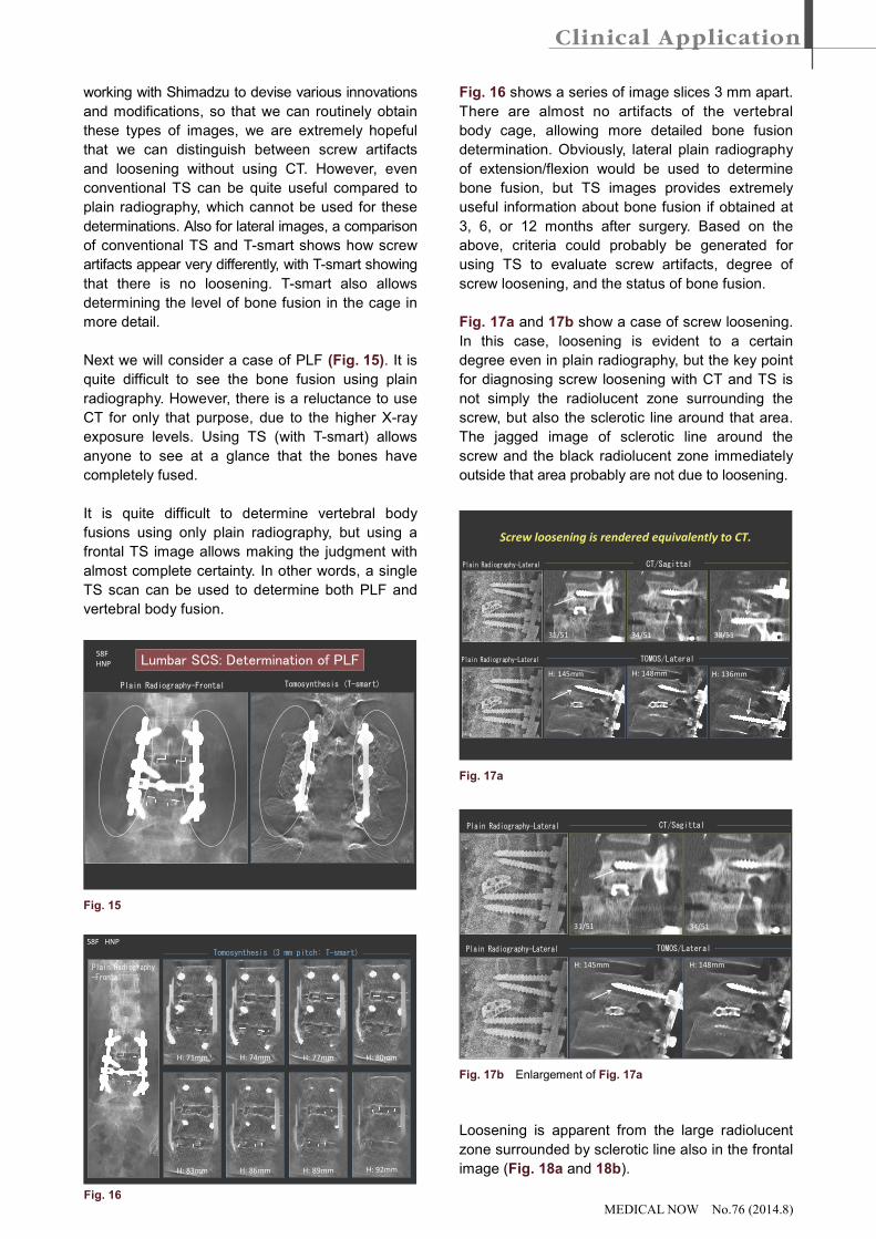
Next we will consider a case of PLF (Fig. 15). It is
quite difficult to see the bone fusion using plain
radiography. However, there is a reluctance to use
CT for only that purpose, due to the higher X-ray
exposure levels. Using TS (with T-smart) allows
anyone to see at a glance that the bones have
completely fused.
It is quite difficult to determine vertebral body
fusions using only plain radiography, but using a
frontal TS image allows making the judgment with
almost complete certainty. In other words, a single
TS scan can be used to determine both PLF and
vertebral body fusion.
58F
HNP
Plain Radiography—Frontal Tomosynthesis (T-smart)
Lumbar SCS: Determination of PLF
Fig. 15
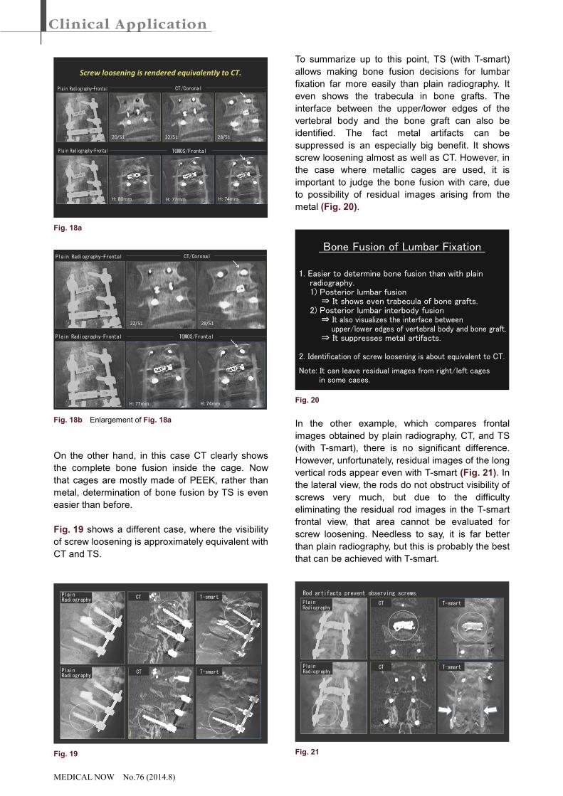
58F HNP
H: 71mm H: 74mm H: 77mm H: 80mm
H: 83mm H: 86mm H: 89mm H: 92mm
Tomosynthesis (3 mm pitch: T-smart)
Plain Radiography—Frontal
Fig. 16 shows a series of image slices 3 mm apart.
There are almost no artifacts of the vertebral
body cage, allowing more detailed bone fusion
determination. Obviously, lateral plain radiography
of extension/flexion would be used to determine
bone fusion, but TS images provides extremely
useful information about bone fusion if obtained at
3, 6, or 12 months after surgery. Based on the
above, criteria could probably be generated for
using TS to evaluate screw artifacts, degree of
screw loosening, and the status of bone fusion.
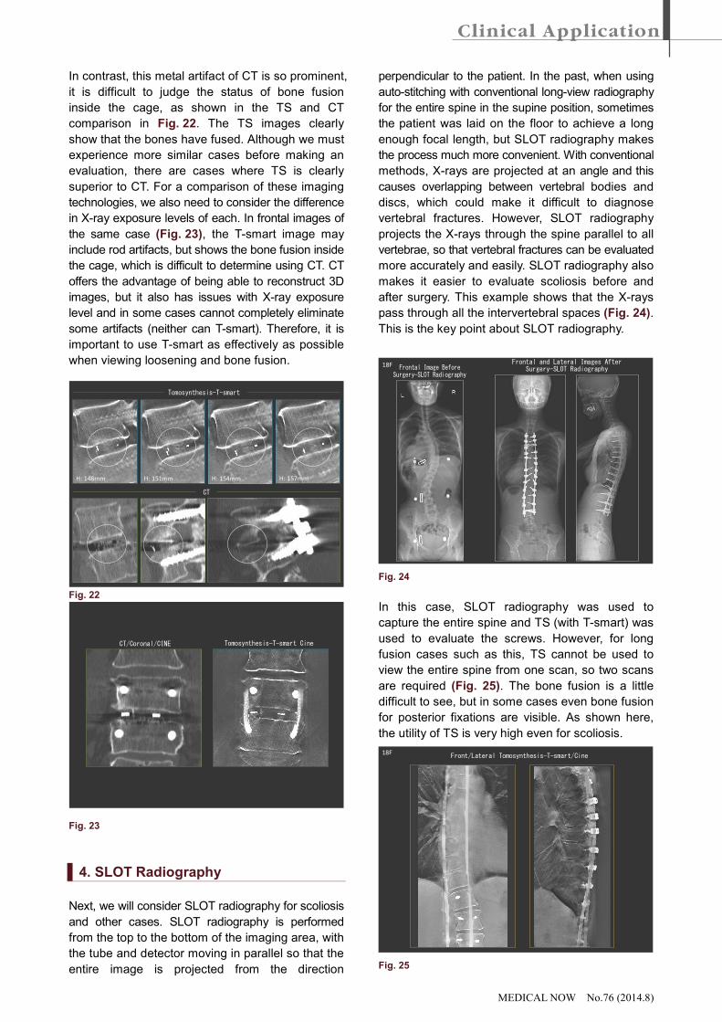
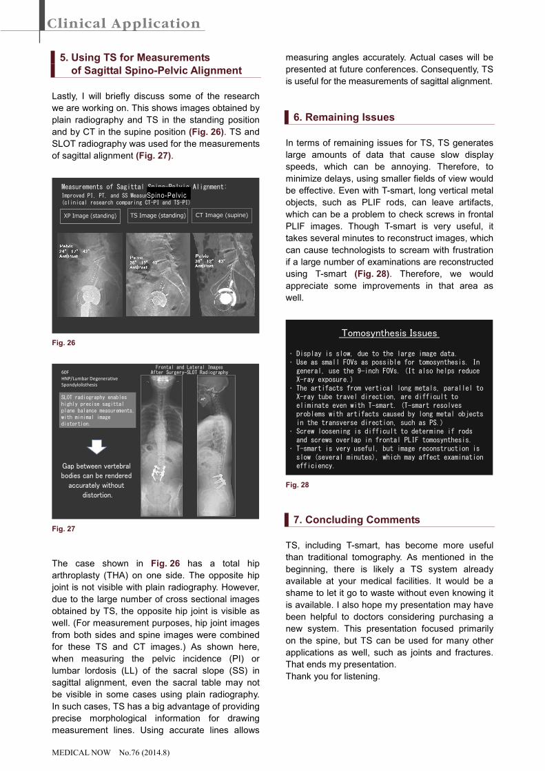
Fig. 17a and 17b show a case of screw loosening.
In this case, loosening is evident to a certain
degree even in plain radiography, but the key point
for diagnosing screw loosening with CT and TS is
not simply the radiolucent zone surrounding the
screw, but also the sclerotic line around that area.
The jagged image of sclerotic line around the
screw and the black radiolucent zone immediately
outside that area probably are not due to loosening.
Plain Radiography—Lateral
CT/Sagittal
TOMOS/Lateral
Plain Radiography—Lateral
H: 136mmH: 148mmH: 145mm
38/5134/5131/51
Screw loosening is rendered equivalently to CT.
Fig. 17a
Plain Radiography—Lateral
CT/Sagittal
TOMOS/Lateral
Plain Radiography—Lateral
H: 148mmH: 145mm
34/5131/51
Fig. 17b Enlargement of Fig. 17a
Loosening is apparent from the large radiolucent
zone surrounded by sclerotic line also in the frontal
image (Fig. 18a and 18b).
Fig. 16
MEDICAL NOW No.76 (2014.8)
Plain Radiography—Frontal
TOMOS/Frontal
CT/Coronal
Plain Radiography—Frontal
22/5120/51
H: 74mmH: 77mmH: 80mm
28/51
Screw loosening is rendered equivalently to CT.
Fig. 18a
Plain Radiography—Frontal
TOMOS/Frontal
CT/Coronal
Plain Radiography—Frontal
22/51
H: 74mmH: 77mm
28/51
Fig. 18b Enlargement of Fig. 18a
On the other hand, in this case CT clearly shows
the complete bone fusion inside the cage. Now
that cages are mostly made of PEEK, rather than
metal, determination of bone fusion by TS is even
easier than before.
Fig. 19 shows a different case, where the visibility
of screw loosening is approximately equivalent with
CT and TS.
PlainRadiography
PlainRadiography
CT
CT
T-smart
T-smart
Fig. 19
To summarize up to this point, TS (with T-smart)
allows making bone fusion decisions for lumbar
fixation far more easily than plain radiography. It
even shows the trabecula in bone grafts. The
interface between the upper/lower edges of the
vertebral body and the bone graft can also be
identified. The fact metal artifacts can be
suppressed is an especially big benefit. It shows
screw loosening almost as well as CT. However, in
the case where metallic cages are used, it is
important to judge the bone fusion with care, due
to possibility of residual images arising from the
metal (Fig. 20).
Bone Fusion of Lumbar Fixation
1. Easier to determine bone fusion than with plain radiography. 1) Posterior lumbar fusion ⇒ It shows even trabecula of bone grafts. 2) Posterior lumbar interbody fusion ⇒ It also visualizes the interface between
upper/lower edges of vertebral body and bone graft. ⇒ It suppresses metal artifacts.
2. Identification of screw loosening is about equivalent to CT.
Note: It can leave residual images from right/left cages in some cases.
Fig. 20
In the other example, which compares frontal
images obtained by plain radiography, CT, and TS
(with T-smart), there is no significant difference.
However, unfortunately, residual images of the long
vertical rods appear even with T-smart (Fig. 21). In
the lateral view, the rods do not obstruct visibility of
screws very much, but due to the difficulty
eliminating the residual rod images in the T-smart
frontal view, that area cannot be evaluated for
screw loosening. Needless to say, it is far better
than plain radiography, but this is probably the best
that can be achieved with T-smart.
Rod artifacts prevent observing screws.
PlainRadiography
CT T-smart
PlainRadiography
CT T-smart
Fig. 21
MEDICAL NOW No.76 (2014.8)
In contrast, this metal artifact of CT is so prominent,
it is difficult to judge the status of bone fusion
inside the cage, as shown in the TS and CT
comparison in Fig. 22. The TS images clearly
show that the bones have fused. Although we must
experience more similar cases before making an
evaluation, there are cases where TS is clearly
superior to CT. For a comparison of these imaging
technologies, we also need to consider the difference
in X-ray exposure levels of each. In frontal images of
the same case (Fig. 23), the T-smart image may
include rod artifacts, but shows the bone fusion inside
the cage, which is difficult to determine using CT. CT
offers the advantage of being able to reconstruct 3D
images, but it also has issues with X-ray exposure
level and in some cases cannot completely eliminate
some artifacts (neither can T-smart). Therefore, it is
important to use T-smart as effectively as possible
when viewing loosening and bone fusion.
Fig. 22
Fig. 23
4. SLOT Radiography
Next, we will consider SLOT radiography for scoliosis
and other cases. SLOT radiography is performed
from the top to the bottom of the imaging area, with
the tube and detector moving in parallel so that the
entire image is projected from the direction
perpendicular to the patient. In the past, when using
auto-stitching with conventional long-view radiography
for the entire spine in the supine position, sometimes
the patient was laid on the floor to achieve a long
enough focal length, but SLOT radiography makes
the process much more convenient. With conventional
methods, X-rays are projected at an angle and this
causes overlapping between vertebral bodies and
discs, which could make it difficult to diagnose
vertebral fractures. However, SLOT radiography
projects the X-rays through the spine parallel to all
vertebrae, so that vertebral fractures can be evaluated
more accurately and easily. SLOT radiography also
makes it easier to evaluate scoliosis before and
after surgery. This example shows that the X-rays
pass through all the intervertebral spaces (Fig. 24).
This is the key point about SLOT radiography.
18F Frontal and Lateral Images AfterSurgery—SLOT RadiographyFrontal Image Before
Surgery—SLOT Radiography
Fig. 24
In this case, SLOT radiography was used to
capture the entire spine and TS (with T-smart) was
used to evaluate the screws. However, for long
fusion cases such as this, TS cannot be used to
view the entire spine from one scan, so two scans
are required (Fig. 25). The bone fusion is a little
difficult to see, but in some cases even bone fusion
for posterior fixations are visible. As shown here,
the utility of TS is very high even for scoliosis.
18FFront/Lateral Tomosynthesis—T-smart/Cine
Fig. 25
H: 148mm H: 151mm H: 154mm H: 157mm
Tomosynthesis—T-smart
CT
CT/Coronal/CINE Tomosynthesis—T-smart Cine
MEDICAL NOW No.76 (2014.8)
5. Using TS for Measurements
of Sagittal Spino-Pelvic Alignment
Lastly, I will briefly discuss some of the research
we are working on. This shows images obtained by
plain radiography and TS in the standing position
and by CT in the supine position (Fig. 26). TS and
SLOT radiography was used for the measurements
of sagittal alignment (Fig. 27).
Fig. 26
60F
HNP/Lumbar Degenerative
Spondylolisthesis
Frontal and Lateral ImagesAfter Surgery—SLOT Radiography
SLOT radiography enableshighly precise sagittalplane balance measurements,with minimal imagedistortion.
Gap between vertebralbodies can be rendered
accurately withoutdistortion.
Fig. 27
The case shown in Fig. 26 has a total hip
arthroplasty (THA) on one side. The opposite hip
joint is not visible with plain radiography. However,
due to the large number of cross sectional images
obtained by TS, the opposite hip joint is visible as
well. (For measurement purposes, hip joint images
from both sides and spine images were combined
for these TS and CT images.) As shown here,
when measuring the pelvic incidence (PI) or
lumbar lordosis (LL) of the sacral slope (SS) in
sagittal alignment, even the sacral table may not
be visible in some cases using plain radiography.
In such cases, TS has a big advantage of providing
precise morphological information for drawing
measurement lines. Using accurate lines allows
measuring angles accurately. Actual cases will be
presented at future conferences. Consequently, TS
is useful for the measurements of sagittal alignment.
6. Remaining Issues
In terms of remaining issues for TS, TS generates
large amounts of data that cause slow display
speeds, which can be annoying. Therefore, to
minimize delays, using smaller fields of view would
be effective. Even with T-smart, long vertical metal
objects, such as PLIF rods, can leave artifacts,
which can be a problem to check screws in frontal
PLIF images. Though T-smart is very useful, it
takes several minutes to reconstruct images, which
can cause technologists to scream with frustration
if a large number of examinations are reconstructed
using T-smart (Fig. 28). Therefore, we would
appreciate some improvements in that area as
well.
Tomosynthesis Issues
• Display is slow, due to the large image data.• Use as small FOVs as possible for tomosynthesis. In
general, use the 9-inch FOVs. (It also helps reduceX-ray exposure.)
• The artifacts from vertical long metals, parallel toX-ray tube travel direction, are difficult toeliminate even with T-smart. (T-smart resolvesproblems with artifacts caused by long metal objectsin the transverse direction, such as PS.)
• Screw loosening is difficult to determine if rodsand screws overlap in frontal PLIF tomosynthesis.
• T-smart is very useful, but image reconstruction isslow (several minutes), which may affect examinationefficiency.
Fig. 28
7. Concluding Comments
TS, including T-smart, has become more useful
than traditional tomography. As mentioned in the
beginning, there is likely a TS system already
available at your medical facilities. It would be a
shame to let it go to waste without even knowing it
is available. I also hope my presentation may have
been helpful to doctors considering purchasing a
new system. This presentation focused primarily
on the spine, but TS can be used for many other
applications as well, such as joints and fractures.
That ends my presentation.
Thank you for listening.
TS Image (standing)XP Image (standing) CT Image (supine)
Measurements of Sagittal Spine-Pelvic Alignment:Improved PI, PT, and SS Measurement Precision(clinical research comparing CT-PI and TS-PI)
Sp in o-P el vi c