Embed Size (px)
Citation preview
90cm Canopy
Rangehood
CRHC9S01
2
Important SafeguardsWhen using electrical appliances, in order to reduce the risk of fi re, electric shock and/or injury, these basic safety precautions should always be followed:
For Your SafetyRead all instructions carefully, even if you arefamiliar with the appliance.
• This appliance is not intended for use by persons (including children) with reduced physical, sensory and mental capabilities, or lack of experience and knowledge, unless they have been given supervision or instruction concerning use of the appliance by a person responsible for their safety.
• Young children should be supervised to ensure that they do not play with the appliance.
• Packaging materials (eg; polystyrene and plastic items) must be kept out of reach of babies and young children at all times due to risk of suffocation.
• Do not use outdoor.
• Keep these instructions in a safe place for future reference.
• There shall be adequate ventilation of the room when the rangehood is used at the same time as appliances burning gas or other fuels.
• There is a fi re risk if cleaning is not carried out in accordance with the instructions.
• Do not fl ambé under the rangehood.
• The air must not be discharged into a fl ue that is used for exhausting fumes from appliances burning gas or other fuels.
NOTE: The minimum safety distance between the top of the oven and the underside of the rangehood must be 650mm.
Compulsory WarningIf the supply cord is damaged, the cord must bereplaced by the manufacturer, its service agentor similarly qualifi ed persons in order to avoid ahazard.
This product has not been designed for any usesother than those specifi ed in this booklet.
Plug must be accessible after installation.
Installation• Always adhere to the minimum safety distance
between the top of the cooker / hob and the under-side of the rangehood:
• 600mm for electric hobs and cookers
• 650mm for gas hobs and cookers
• It is prohibited to fi t a rangehood over a solid fuel stove.
• This appliance must not be connected to a chimney or vent fl ue which is in use.
• This appliance is not to b vented into the roof cavity, must exit into open air.
• Professional advice should be sought if ducting this appliance into a chimney or vent fl ue which is no longer in use.
• This appliance should not be connected to ducting which ventilates rooms with fi replaces.
• Attention should be given to ensure that any applicable regulations concerning discharge of exhaust air are fulfi lled.
• This appliance should be installed and maintained by a suitably qualifi ed and competent person in accordance with the relevant safety regulations.
• Before connecting the appliance to the mains supply, ensure that the voltage and frequency details on the rating plate are consistent with the source of supply.
• Always disconnect the appliance from the mains supply before any cleaning and maintenance.
3
Operation (Extraction Mode Only)• Care should be taken if operating the
rangehood at the same time, and in the same vicinity, as other heating appliances which depend on air for their operation. This may include such appliances as wood, oil, gas or coal-fi red boilers and heaters, gas ovens, hobs and cookers, and continuous fl ow or other water heaters.
• In addition, harmful gases from the heating appliance may be drawn from the chimney / ducting back into the room with potentially fatal consequences.
• Adequate ventilation can be maintained by:
• The use of air inlets by means of windows, doors and external wall vents
• Ensuring none of the ventilation openings are blocked
• Using either the rangehood or heating appliance in isolation
4
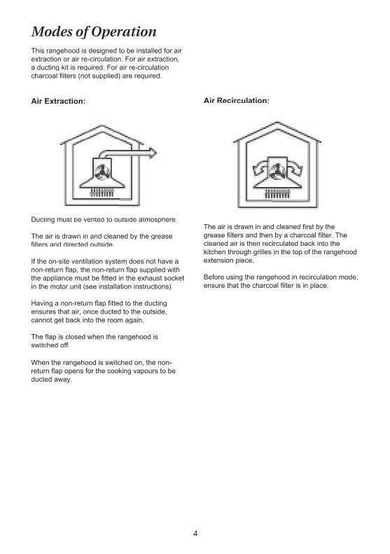
Air Recirculation:
The air is drawn in and cleaned fi rst by the grease fi lters and then by a charcoal fi lter. The cleaned air is then recirculated back into the kitchen through grilles in the top of the rangehood extension piece.
Before using the rangehood in recirculation mode, ensure that the charcoal fi lter is in place.
Modes of OperationThis rangehood is designed to be installed for air extraction or air re-circulation. For air extraction, a ducting kit is required. For air re-circulation charcoal fi lters (not supplied) are required.
Air Extraction:
Ducting must be vented to outside atmosphere.
The air is drawn in and cleaned by the grease fi lters and directed outside.
If the on-site ventilation system does not have a non-return fl ap, the non-return fl ap supplied with the appliance must be fi tted in the exhaust socket in the motor unit (see installation instructions).
Having a non-return fl ap fi tted to the ducting ensures that air, once ducted to the outside, cannot get back into the room again.
The fl ap is closed when the rangehood is switched off.
When the rangehood is switched on, the non-return fl ap opens for the cooking vapours to be ducted away.
5
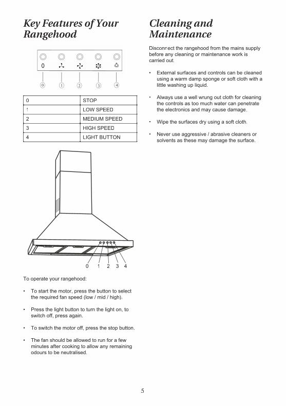
Key Features of Your Rangehood
0 STOP
1 LOW SPEED
2 MEDIUM SPEED
3 HIGH SPEED
4 LIGHT BUTTON
To operate your rangehood:
• To start the motor, press the button to select the required fan speed (low / mid / high).
• Press the light button to turn the light on, to switch off, press again.
• To switch the motor off, press the stop button.
• The fan should be allowed to run for a few minutes after cooking to allow any remaining odours to be neutralised.
Cleaning and Maintenance Disconnect the rangehood from the mains supply before any cleaning or maintenance work is carried out. • External surfaces and controls can be cleaned
using a warm damp sponge or soft cloth with a little washing up liquid.
• Always use a well wrung out cloth for cleaning the controls as too much water can penetrate the electronics and may cause damage.
• Wipe the surfaces dry using a soft cloth.
• Never use aggressive / abrasive cleaners or solvents as these may damage the surface.
0 1 2 3 4
6
Aluminium Grease FiltersThe re-usable aluminium fi lters supplied with this appliance should be cleaned every 3 – 4 weeks to avoid a build up of grease. • To remove the grease fi lter, release the
locking mechanism at the front of the fi lter, lower the fi lter slightly and unhook it at the back taking care to hold the fi lter securely at all times.
• To clean the fi lter, place it into a bowl of warm soapy water and soak for about 2 – 3 minutes
• Clean the mesh with a soft brush.
• Do not apply too much pressure as the mesh is delicate and will damage easily.
• Do not use a corrosive detergent.
• Whilst the fi lters are removed, clean off any residual grease from the housing unit to avoid the risk of fi re.
• After cleaning, leave the fi lters to dry before replacing them on the appliance.
• When replacing the grease fi lters, ensure that the locking mechanism is facing down.
Fitting and Replacing the Active Carbon FilterIf the rangehood is used in re-circulation mode, an activated charcoal fi lter must be inserted. These charcoal fi lters are designed to absorb cooking odours and are located in the canopy above the grease fi lters.
Before fi tting or replacing charcoal fi lters, the grease fi lters must fi rst be removed (see previous section).
The charcoal fi lter is not washable and should be replaced when it no longer absorbs kitchen odours effectively. Under normal use, this would be approximately every 6 months or more frequently for particularly heavy usage.
Used charcoal fi lters can be disposed of with normal household waste.
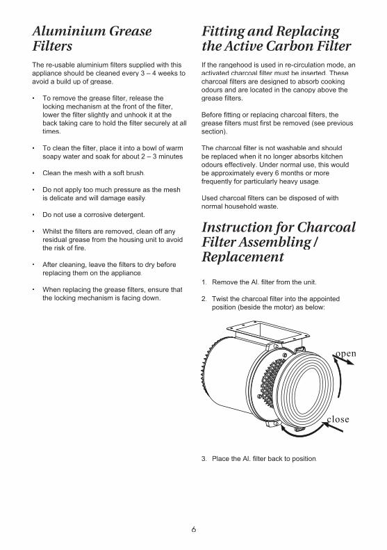
Instruction for Charcoal Filter Assembling /Replacement
1. Remove the Al. fi lter from the unit.
2. Twist the charcoal fi lter into the appointed position (beside the motor) as below:
3. Place the Al. fi lter back to position.
7
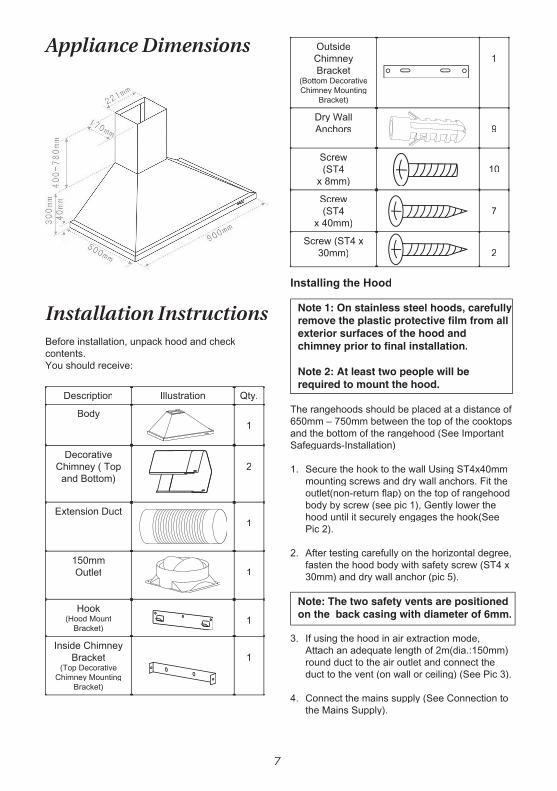
Appliance Dimensions
Installation Instructions Before installation, unpack hood and check contents.You should receive:
Description Illustration Qty.
Body1
Decorative Chimney ( Top and Bottom)
2
Extension Duct1
150mm Outlet 1
Hook(Hood Mount
Bracket)1
Inside Chimney Bracket
(Top Decorative Chimney Mounting
Bracket)
1
Outside Chimney Bracket
(Bottom Decorative Chimney Mounting
Bracket)
1
Dry Wall Anchors 9
Screw(ST4
x 8mm)10
Screw(ST4
x 40mm)7
Screw (ST4 x 30mm) 2
Installing the Hood
Note 1: On stainless steel hoods, carefully remove the plastic protective fi lm from all exterior surfaces of the hood and chimney prior to fi nal installation.
Note 2: At least two people will be required to mount the hood.
The rangehoods should be placed at a distance of 650mm – 750mm between the top of the cooktops and the bottom of the rangehood (See Important Safeguards-Installation)
1. Secure the hook to the wall Using ST4x40mm mounting screws and dry wall anchors. Fit the outlet(non-return fl ap) on the top of rangehood body by screw (see pic 1), Gently lower the hood until it securely engages the hook(See Pic 2).
2. After testing carefully on the horizontal degree, fasten the hood body with safety screw (ST4 x 30mm) and dry wall anchor (pic 5).
Note: The two safety vents are positioned on the back casing with diameter of 6mm.
3. If using the hood in air extraction mode, Attach an adequate length of 2m(dia.:150mm) round duct to the air outlet and connect the duct to the vent (on wall or ceiling) (See Pic 3).
4. Connect the mains supply (See Connection to the Mains Supply).
8
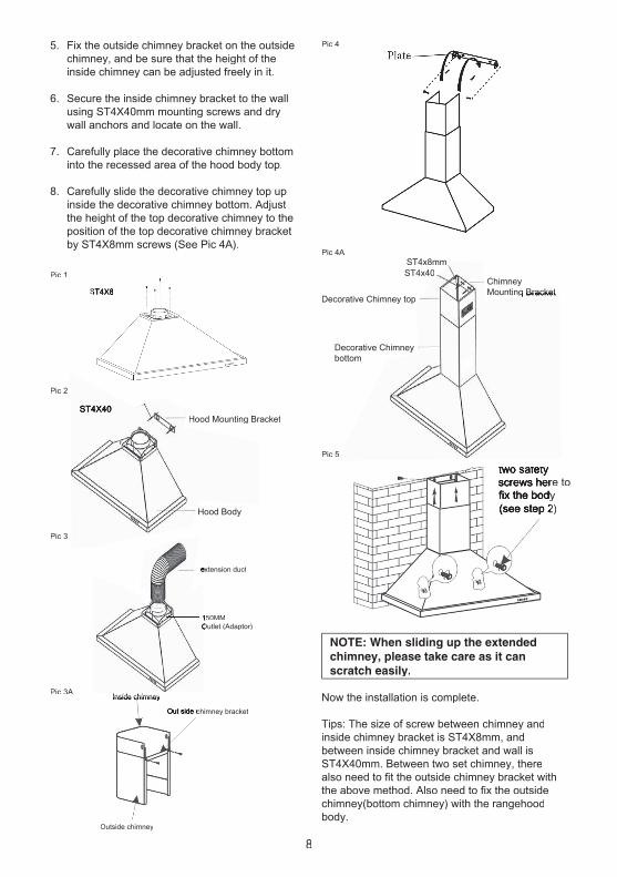
two safety screws here to screws here to fi x the bodyfi x the body(see step 2)(see step 2)
Pic 5
5. Fix the outside chimney bracket on the outside chimney, and be sure that the height of the inside chimney can be adjusted freely in it.
6. Secure the inside chimney bracket to the wall using ST4X40mm mounting screws and dry wall anchors and locate on the wall.
7. Carefully place the decorative chimney bottom into the recessed area of the hood body top.
8. Carefully slide the decorative chimney top up inside the decorative chimney bottom. Adjust the height of the top decorative chimney to the position of the top decorative chimney bracket by ST4X8mm screws (See Pic 4A).
NOTE: When sliding up the extended chimney, please take care as it can scratch easily.
Now the installation is complete.
Tips: The size of screw between chimney andinside chimney bracket is ST4X8mm, andbetween inside chimney bracket and wall isST4X40mm. Between two set chimney, therealso need to fi t the outside chimney bracket withthe above method. Also need to fi x the outsidechimney(bottom chimney) with the rangehoodbody.
Pic 1
ST4X8ST4X8
Hood Body
Hood Mounting BracketST4X40
Pic 2
Pic 3
150MM 150MM Outlet (Adaptor)Outlet (Adaptor)
extension ductextension duct
Chimney Mounting BracketMounting Bracket
ST4x8mmST4x40
Decorative Chimney top
Decorative Chimney bottom
Pic 4
Pic 4A
Pic 3AInside chimneyInside chimneyInside chimney
Out side chimney bracketOut side chimney bracket
Outside chimney

9
Notes

10
Notes
11
8. This warranty does not apply to damage caused if your appliance has been dismantled, repaired or serviced by any person other than someone authorised by the Company.
9. If you live outside the service area of the Company or one of its service agents, this warranty does not cover the cost of transport of the appliance for service nor the service agent’s travelling costs to and from your home.
10. If you are required to transport the appliance to the Company or its service agent, you must ensure it is securely packed and insured. The Company does not accept any responsibility for loss or damage of the appliance prior to it being received by the Company or its service agent.
11. This warranty does not cover loss, damage or expense to this appliance caused directly or indirectly by power surges, electrical storm damage or incorrect power current.
12. The Company (and any company related to the Company) will not be liable for any special, incidental or consequential damages or for loss, damage or expense or for personal injury or loss or destruction of property arising directly or indirectly from the use or inability to use this appliance or any of its parts.
13. This warranty applies only to the original buyer.
14. Access must be granted within normal working hours and our Company or service agents must have easy access to the appliance. Charges will be the responsibility of the purchaser where the service technician cannot obtain easy access to remove the appliance for inspection prior to repair.
15. Proof that the product was installed by a licenced electrician ( as per State & territory legislation) must be produced to obtain in-home warranty service.
16. At the completion of the initial installation an electrical safety certifi cate must be obtained from the Installer.
WarrantyThe benefi ts conferred by this warranty are in addition to all implied warranties, other rights and remedies in respect of the product which the consumer has under the Trade Practices Act and similar State and Territory Laws.
The original purchaser of this Bellini product is provided with the following warranty, subject to the following conditions.
This product is warranted for a period of 2 years from the date of purchase for all parts defective inworkmanship or materials.
PRIVACY
You acknowledge that in the event that you make a warranty claim, it will be necessary for GSM Sales Pty Ltd and its Authorised Service Centres to exchange information in relation to you to enable GSM Sales Pty Ltd to meet is obligations under this warranty.
WARRANTY CONDITIONS
1. This warranty is only valid for appliances used according to the manufacturer’s instructions.
2. This appliance must not be modifi ed or changed in any way.
3. Connection must be to the voltage requirements as specifi ed in the ratings label located on the product.
4. The manufacturer does not accept liability for any direct or consequential damage, loss or other expense arising from misuse or incorrect installation and operation of the appliance.
5. Warranty will only be given where proof of purchase is provided, e.g. original invoice.
6. Not designed or warranted for industrial or commercial use. (Commerical use applies to shops, offi ces, schools, factories & workshops, etc.)
7. This warranty applies only for mainland Australia and Tasmania.

12
�����������������
������������������������������������������������������������������������������������������������������������������
��������������������������������������������������������������������������������������������
�����������������������������������
�������������������������������
DO NOT SEND IN THIS WARRANTY
Fill out the following details and fi le with your purchase invoice.
RETAIN & FILE WITH YOUR RECEIPT
GSM Sales Pty Ltd reserves the right to discontinue items, modify designs and change specifi cations without incurring obligation. Whilst every effort is made to ensure that descriptions, specifi cations and other information in this publication is correct, no warranty is given in respect thereof and the company shall not be liable for any errors therein.
PLEASE NOTE:
Fill out the following details and fi le with yourpurchase invoice.
Proof of purchase date must be presented to theservice technican prior to warranty service.Document as per warranty conditions (15 & 16) are also required by State & National authorities.
Whilst every effort is made to ensure thatdescriptions, specifi cations and other informationin this publication is correct, no warranty is givenin respect thereof and the company shall not beliable for any errors therein.
For warranty service contact 1300 373 199 to connect you to your nearest Authorised Service Centre.
Purchased from:
Co. Name:
Address:
Date of Purchase:
NOTE: Consistent with our continuing product development policy, improvements may have been made which render the contents of this package slightly different to that shown.
Model No. CRHC9S01April 2009