Embed Size (px)
Citation preview
Bulletin 71.1:95
95 Series Industrial Pressure RegulatorsThe 95 Series regulator is a compact, large-capacity, self-operated pressure regulator (see figures 1, 2 and 3).The unit is available in 1/4 through 2-inch sizes and is offered in several different end connection configurations.They are designed to handle pressures up to 600 psig (41.4 bar) and temperatures up to 650°F (343°C).
This product can help solve the toughest pressure control applications. Typical applications include superheatedsteam, steam tracing, nitrogen purging, boiler feed water, process chemicals, cooling water, test fixtures, washtanks, sterilizers/autoclaves, fuel lines, pneumatic supply, and many others.
Type 95H
W0077-1 / IL
Features
D Handwheels—Allow easy pressure set-ting changes and are standard on Types 95LD,95HD, and optional on the 1/2-inch body size ofthe Types 95L and 95H regulators. Tee-handlesare optional on all other Types 95L and 95Hbody sizes
D Rugged Construction—Available in avariety of materials including cast iron, carbon steel,stainless steel, Monel, Hastelloy C, Kalrezt andVitont to address the toughest service conditions.Severe service elastomers and corrosion resistanttrims are also available � excellent fluid compatibility
D Versatile—Can be used with all processmedia, air, steam, gas, water, liquids (oils andprocess chemicals), oxygen and cyrogenics
D Self Operated—Designmaximizes speed of response
D Tight Shutoff With ElastomerSeats—Metal seats available for hightemperatures
D Robust—Up to 600 psig(41.4 bar) inlet pressure
D P1 = P2—Inlet equals outlet ratingin 95H series up to 600 psig
8/97
D Easy Maintenance—Seating parts are easilyaccessible by removing the plug on the bottom ofthe regulator
D Differential Pressure Capability—Spring-loaded TFE packing and tapped con-nections permit pressure loading of the Types95LD and 95HD spring cases
D Special Service Capabilities—Optionalmaterials are available for applications handlingsour gases, cryogenics, and superheatedsteam. NACE construction complies withMR0175-92
D Grafoil Gaskets—For hightemperature applications up to650_F (343_C) (optional)
D Set Pressures To 400 Psig (27.4 Bar)
D Multiple End Connection Options—To match your application
D Large Turndown Ratio—Noneed for low Cv trims at low flows
Bulletin 71.1:95
SpecificationsAvailable ConfigurationsType 95L: Low-pressure regulator for 2 to 30 psig(0.1 to 2.0 bar) outlet pressures
Type 95H: High-pressure regulator for 5 to 150psig (0.34 to 10 bar) outlet pressuresType 95LD: Low-pressure differential regulator for2 to 30 psig (0.1 to 2.0 bar) differentialpressures with handwheels and packing box
Type 95HD: High-pressure differential regulator for5 to 150 psig (0.34 to 10 bar) differential pressureswith handwheel and packing box
Type 95HP: High-pressure regulator for 5 to 400psig (0.34 to 28 bar) outlet pressures (soft seated)
Type 95HT: High-pressure/high temperatureregulator for 5 to 300 psig (0.34 to 21 bar) outletpressures (metal seat) and up to 650°F (343°C)
Type 95LC: Low-pressure regulator for 2 to 30psig (0.1 to 2.0 bar) outlet pressures for cold tem-perature applications down to -325°F (-198°C)
Type 95HC: High-pressure regulator for 5 to 150psig (0.34 to 10 bar) outlet pressures for coldtemperature applications down to -325°F (-198°C)
Body and Orifice Sizes1/4-inch body: 1/4-inch (6.4 mm) orifice1/2-inch body: 3/8-inch (9.5 mm) orifice3/4 and 1-inch bodies: 9/16-inch (14.3 mm)orifice
1-1/2 and 2-inch bodies: 1-1/16-inch (27 mm)orifice
End Connection StyleNPT screwed, ANSI flanged; all sizes are fabricatedwith slip-on flanges and are 14-inches face to face(DIN flanged; 356 mm face to face), 150 RF,300RF, 600RF or SWE
Maximum Pressures(1)
See table 3
Outlet or Differential Pressure RangesSee table 5
Elastomer Temperature Ranges(1)
Nitrile Parts: -40 to 180°F (-40 to 82°C)Neoprene Parts: -40 to 180°F (-40 to 82°C)Fluoroelastomer Parts: 0 to 300°F (-18 to 149°C)hot water limited to 200°F (93°C)
Ethylenepropylene Parts: -40 to 450°F (-40 to232°C)
PTFE: -325 to 450°F (-198 to 232°C)
Spring Case ConstructionVent is a drilled untapped hole (standard),NPT (optional) See figure 6On Types 95HD and 95LD a NPT tapped vent holeis standard
1. The pressure/temperature limits in this bulletin and any applicable standard or code limitat
2
Allowable Temperature Ranges for Metal Parts
Body DesignTypes 95H,95HD, 95L,
95LD and 95HPType 95HT Types 95LC
and 95HC
Cast Iron Bodyand Spring
Case
-40 to 406_F(-40 to 208_C)
-40 to 406_F(-40 to 208_C)
Not available
Steel Body andSpring Case
-20 to 450_F(-29 to 232_C)
-20 to 650_F(-29 to 343_C)
Not available
Stainless SteelBody and
Spring Case
-40 to 450_F(-40 to 232_C)
-40 to 550_F(-40 to 287_C)
-325 to 550_F(-198 to 287_C)
Pressure Setting AdjustmentTypes 95L, 95H, 95HT, 95HP, 95LC and 95HC:Adjusting screw (standard),Handwheel/Tee handle (optional) 1/2-inch bodieshave a handwheel all other sizes have tee handles
Types 95LD and 95HD: Handwheel for adjustment
Pressure RegistrationTypes 95L, 95H, 95HT, 95HP, 95LC and 95HC:Internal
Types 95LD and 95HD: Internal combined withoutside pressure source for differential pressure
Typical Regulating CapacitiesAir: See tables 8, 9, 10, 11 and 12Steam: See tables 13, 14, 15, 16 and 17Water: See tables 18, 19, 20, 21 and 22
Shutoff Classification Per ANSI/FCI 70-2-1975R1990)
Metal Seats: Class IV is standardElastomer Seats: Class VI or betterPTFE: Class V
Wide Open Flow Coefficients for Relief SizingSee table 4
Pressure ConnectionsSee figure 6
Construction MaterialsSee table 6
Common Services and Material CompatibilitySee table 7
Approximate WeightTypes 95H, 95HD, 95HT, 95HP and 95HC:1/4-inch body: 4 lb (1.8 kg)1/2-inch body: 8 lb (3.6 kg)3/4 and 1 inch bodies: 20 lb (9.1 kg)1-1/2 and 2-inch bodies: 73 lb (33.1 kg)
Types 95L, 95LD and 95LC1/4-inch body: 6 lb (2.7 kg)1/2-inch body: 12 lb (5.4 kg)3/4 and 1-inch bodies: 32 lb (14.5 kg)
ion for this regulator should not be exceeded.
Bulletin 71.1:95
W509
Figure
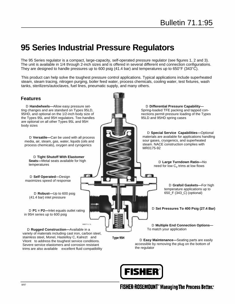
TYPE 95LD
W1894-1 / IL
2. Exterior Views of 95 Series Regulators
TYPE 95HD
1894-1 / IL
WTYPE 95LD (FLANGED)W6195 / IL
TYPE 95L
1 / IL
TYPE 95H
W5092 / IL
3
Bulletin 71.1:95
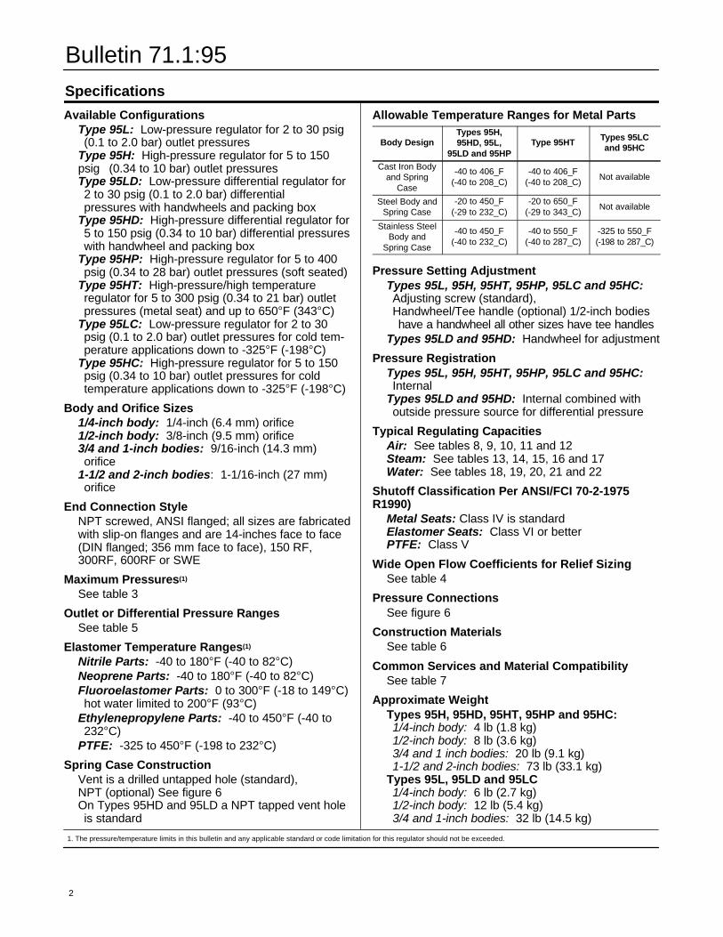
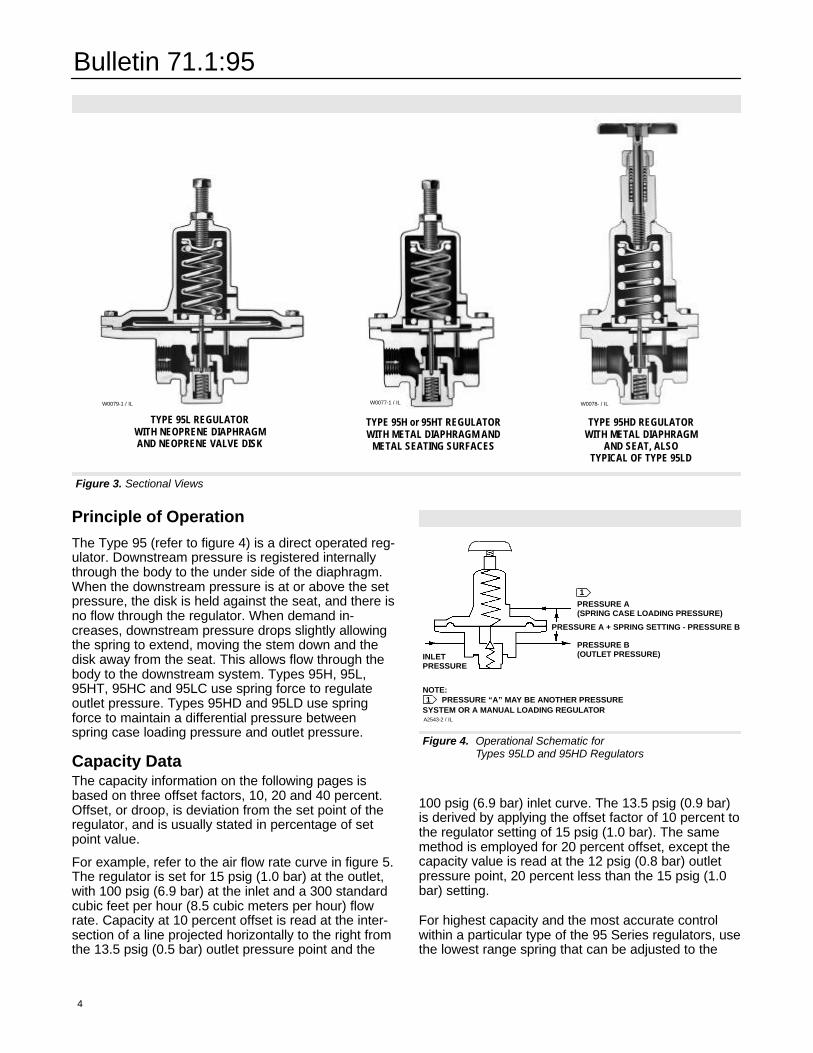
Figure 3. Sectional Views
TYPE 95L REGULATORWITH NEOPRENE DIAPHRAGMAND NEOPRENE VALVE DISK
W0079-1 / IL
4
TYPE 95H or 95HT REGULATORWITH METAL DIAPHRAGM AND
METAL SEATING SURFACES
W0077-1 / IL
TYPE 95HD REGULATORWITH METAL DIAPHRAGM
AND SEAT, ALSOTYPICAL OF TYPE 95LD
W0078- / IL
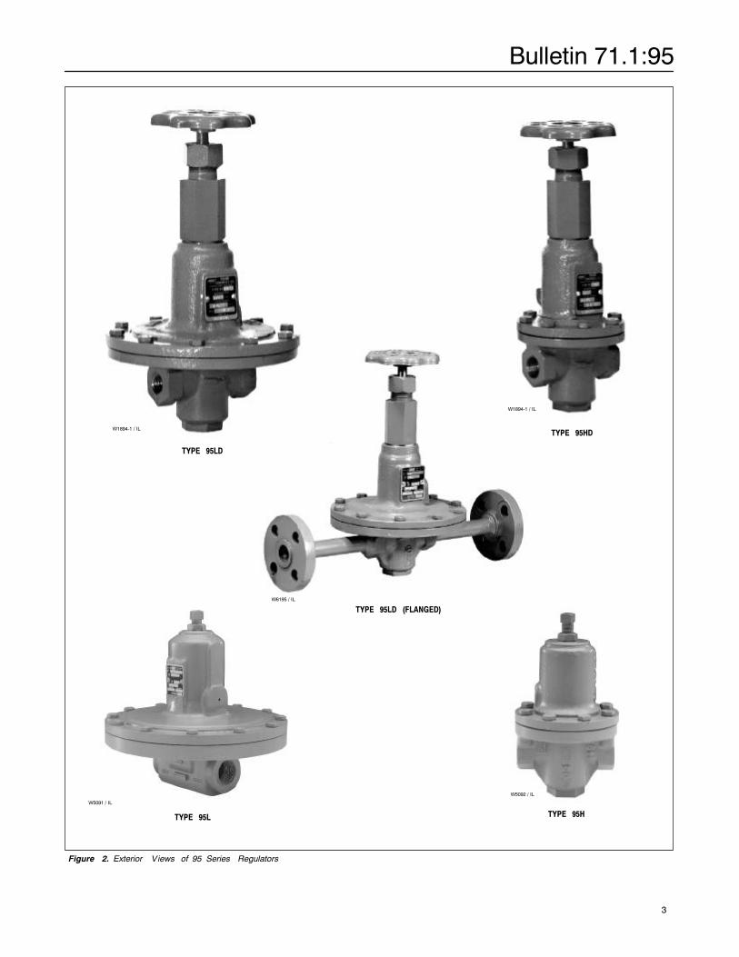
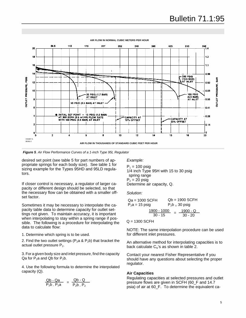
Principle of OperationThe Type 95 (refer to figure 4) is a direct operated reg-ulator. Downstream pressure is registered internallythrough the body to the under side of the diaphragm.When the downstream pressure is at or above the setpressure, the disk is held against the seat, and there isno flow through the regulator. When demand in-creases, downstream pressure drops slightly allowingthe spring to extend, moving the stem down and thedisk away from the seat. This allows flow through thebody to the downstream system. Types 95H, 95L,95HT, 95HC and 95LC use spring force to regulateoutlet pressure. Types 95HD and 95LD use springforce to maintain a differential pressure betweenspring case loading pressure and outlet pressure.
Figure 4. Operational Schematic forTypes 95LD and 95HD Regulators
PRESSURE A(SPRING CASE LOADING PRESSURE)
PRESSURE A + SPRING SETTING - PRESSURE B
PRESSURE B(OUTLET PRESSURE)INLET
PRESSURE
1
NOTE:PRESSURE “A” MAY BE ANOTHER PRESSURE
SYSTEM OR A MANUAL LOADING REGULATOR1
A2543-2 / IL
Capacity DataThe capacity information on the following pages isbased on three offset factors, 10, 20 and 40 percent.Offset, or droop, is deviation from the set point of theregulator, and is usually stated in percentage of setpoint value.
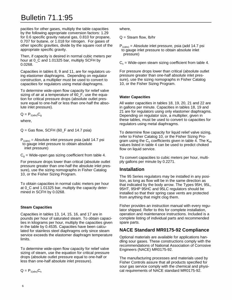
For example, refer to the air flow rate curve in figure 5.The regulator is set for 15 psig (1.0 bar) at the outlet,with 100 psig (6.9 bar) at the inlet and a 300 standardcubic feet per hour (8.5 cubic meters per hour) flowrate. Capacity at 10 percent offset is read at the inter-section of a line projected horizontally to the right fromthe 13.5 psig (0.5 bar) outlet pressure point and the
100 psig (6.9 bar) inlet curve. The 13.5 psig (0.9 bar)is derived by applying the offset factor of 10 percent tothe regulator setting of 15 psig (1.0 bar). The samemethod is employed for 20 percent offset, except thecapacity value is read at the 12 psig (0.8 bar) outletpressure point, 20 percent less than the 15 psig (1.0bar) setting.
For highest capacity and the most accurate controlwithin a particular type of the 95 Series regulators, usethe lowest range spring that can be adjusted to the
Bulletin 71.1:95
desired set point (see table 5 for part numbers of ap-propriate springs for each body size). See table 1 forsizing example for the Types 95HD and 95LD regula-tors.
If closer control is necessary, a regulator of larger ca-pacity or different design should be selected, so thatthe necessary flow can be obtained with a smaller off-set factor.
Sometimes it may be necessary to interpolate the ca-pacity table data to determine capacity for outlet set-tings not given. To maintain accuracy, it is importantwhen interpolating to stay within a spring range if pos-sible. The following is a procedure for interpolating thedata to calculate flow:
1. Determine which spring is to be used.
2. Find the two outlet settings (P2a & P2b) that bracket theactual outlet pressure P2.
3. For a given body size and inlet pressure, find the capacityQa for P2a and Qb for P2b.
4. Use the following formula to determine the interpolatedcapacity (Q).
Qb - QP2b - P2
=Qb - QaP2b - P2a
Example:
P1 = 100 psig1/4 inch Type 95H with 15 to 30 psigspring range
P2 = 20 psigDetermine air capacity, Q.
Solution:
Qa = 1000 SCFH
1900 - 1000 1900 - Q30 - 20
=30 - 15
Qb = 1900 SCFHP2b = 30 psigP2a = 15 psig
Q = 1300 SCFH
NOTE: The same interpolation procedure can be usedfor different inlet pressures.
An alternative method for interpolating capacities is toback calculate Cv’s as shown in table 2.
Contact your nearest Fisher Representative if youshould have any questions about selecting the properregulator.
Figure 5. Air Flow Performance Curves of a 1-inch Type 95L Regulator
CE4967-AB0392-2
AIR FLOW IN THOUSANDS OF STANDARD CUBIC FEET PER HOUR
AIR FLOW IN NORMAL CUBIC METERS PER HOUR
Air CapacitiesRegulating capacities at selected pressures and outletpressure flows are given in SCFH (60_F and 14.7psia) of air at 60_F. To determine the equivalent ca-
5
Bulletin 71.1:95
pacities for other gases, multiply the table capacitiesby the following appropriate conversion factors: 1.29for 0.6 specific gravity natural gas, 0.810 for propane,0.707 for butane, or 1.018 for nitrogen. For gases ofother specific gravities, divide by the square root of theappropriate specific gravity.Then, if capacity is desired in normal cubic meters perhour at 0_C and 1.01325 bar, multiply SCFH by0.0268.
Capacities in tables 8, 9 and 11, are for regulators us-ing elastomer diaphragms. Depending on regulatorconstruction, a multiplier must be used to convert tocapacities for regulators using metal diaphragms.
To determine wide-open flow capacity for relief valvesizing of air at a temperature of 60_F, use the equa-tion for critical pressure drops (absolute outlet pres-sure equal to one-half or less than one-half the abso-lute inlet pressure).
Q = P1(abs)Cg
where,
Q = Gas flow, SCFH (60_F and 14.7 psia)
P1(abs) = Absolute inlet pressure psia (add 14.7 psito gauge inlet pressure to obtain absoluteinlet pressure)
Cg = Wide-open gas sizing coefficient from table 4.
For pressure drops lower than critical (absolute outletpressure greater than one-half the absolute inlet pres-sure), use the sizing nomographs in Fisher Catalog10, or the Fisher Sizing Program.
To obtain capacities in normal cubic meters per hourat 0_C and 1.01325 bar, multiply the capacity deter-mined in SCFH by 0.0268.
Steam Capacities
Capacities in tables 13, 14, 15, 16, and 17 are inpounds per hour of saturated steam. To obtain capaci-ties in kilograms per hour, multiply the capacities givenin the table by 0.4535. Capacities have been calcu-lated for stainless steel diaphragms only since steamservice exceeds the elastomer diaphragm temperaturelimits.
To determine wide-open flow capacity for relief valvesizing of steam, use the equation for critical pressuredrops (absolute outlet pressure equal to one-half orless than one-half absolute inlet pressure).
Q = P1(abs)Cs
6
where,
Q = Steam flow, lb/hr
P1(abs) = Absolute inlet pressure, psia (add 14.7 psito gauge inlet pressure to obtain absolute inletpressure)
Cs = Wide-open steam sizing coefficient from table 4.
For pressure drops lower than critical (absolute outletpressure greater than one-half absolute inlet pres-sure), use the sizing nomographs in Fisher Catalog10, or the Fisher Sizing Program.
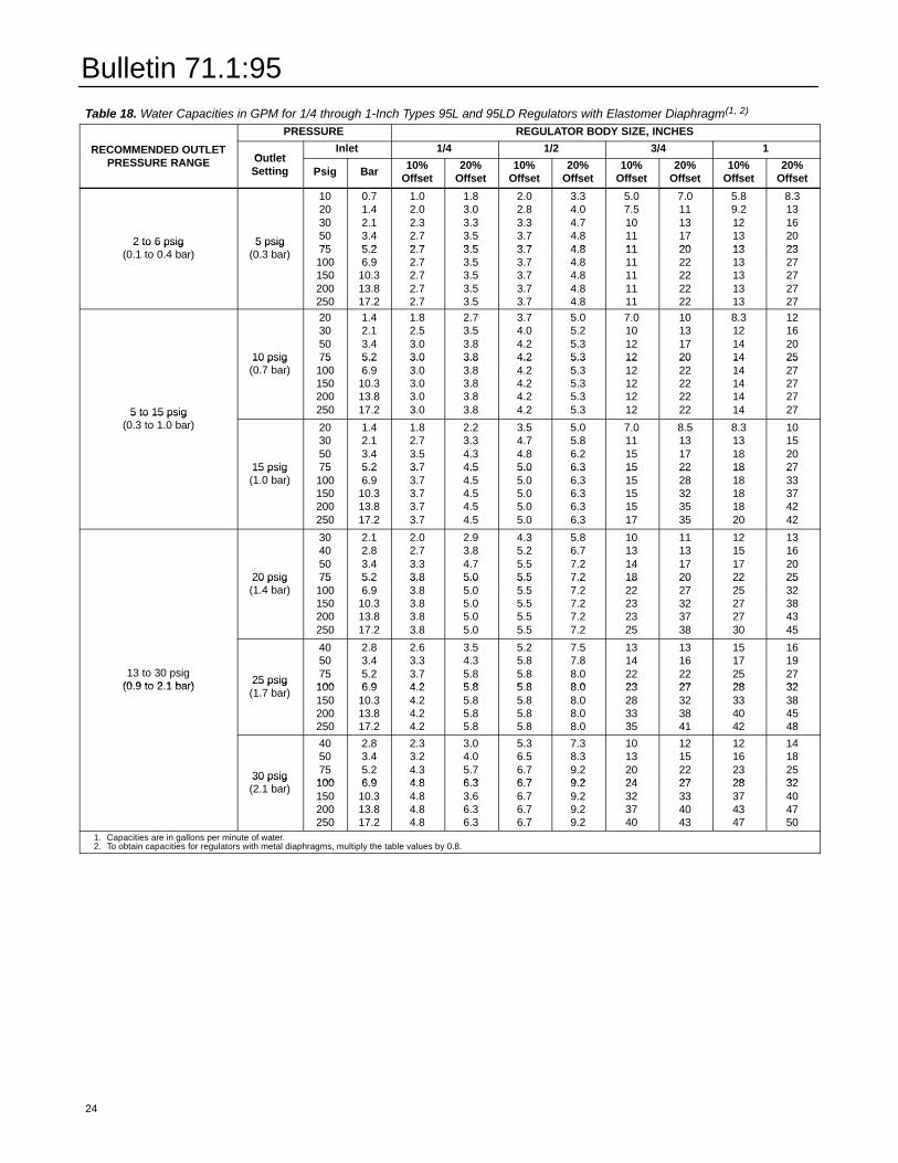
Water Capacities
All water capacities in tables 18, 19, 20, 21 and 22 arein gallons per minute. Capacities in tables 18, 19 and21 are for regulators using only elastomer diaphragms.Depending on regulator size, a multiplier, given inthese tables, must be used to convert to capacities forregulators using metal diaphragms.
To determine flow capacity for liquid relief valve sizing,refer to Fisher Catalog 10, or the Fisher Sizing Pro-gram using the Cv coefficients given in table 4. The Kmvalues listed in table 4 can be used to predict chokedflow on liquid service.
To convert capacities to cubic meters per hour, multi-ply gallons per minute by 0.2271.
InstallationThe 95 Series regulators may be installed in any posi-tion, as long as flow will be in the same direction asthat indicated by the body arrow. The Types 95H, 95L,95HT, 95HP 95HC and 95LC regulators should beinstalled so that their spring case vents are protectedfrom anything that might clog them.
Fisher provides an instruction manual with every regu-lator shipped. Refer to this for complete installation,operation and maintenance instructions. Included is acomplete listing of individual parts and recommendedspare parts.
NACE Standard MR0175-92 ComplianceOptional materials are available for applications han-dling sour gases. These constructions comply with therecommendations of National Association of CorrosiveEngineers (NACE) MR0175-92.
The manufacturing processes and materials used byFisher Controls assure that all products specified forsour gas service comply with the chemical and physi-cal requirements of NACE standard MR0175-92.
Bulletin 71.1:95
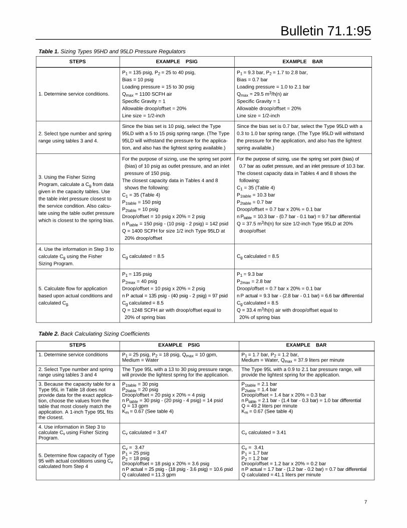
Table 1. Sizing Types 95HD and 95LD Pressure RegulatorsSTEPS EXAMPLE � PSIG EXAMPLE � BAR
1. Determine service conditions.
P1 = 135 psig, P2 = 25 to 40 psig,Bias = 10 psigLoading pressure = 15 to 30 psigQmax = 1100 SCFH airSpecific Gravity = 1Allowable droop/offset = 20%Line size = 1/2-inch
P1 = 9.3 bar, P2 = 1.7 to 2.8 bar,Bias = 0.7 barLoading pressure = 1.0 to 2.1 barQmax = 29.5 m3/h(n) airSpecific Gravity = 1Allowable droop/offset = 20%Line size = 1/2-inch
2. Select type number and springrange using tables 3 and 4.
Since the bias set is 10 psig, select the Type95LD with a 5 to 15 psig spring range. (The Type95LD will withstand the pressure for the applica-tion, and also has the lightest spring available.)
Since the bias set is 0.7 bar, select the Type 95LD with a0.3 to 1.0 bar spring range. (The Type 95LD will withstandthe pressure for the application, and also has the lightestspring available.)
3. Using the Fisher SizingProgram, calculate a Cg from datagiven in the capacity tables. Usethe table inlet pressure closest tothe service condition. Also calcu-late using the table outlet pressurewhich is closest to the spring bias.
For the purpose of sizing, use the spring set point(bias) of 10 psig as outlet pressure, and an inletpressure of 150 psig.
The closest capacity data in Tables 4 and 8shows the following:
C1 = 35 (Table 4)P1table = 150 psigP2table = 10 psigDroop/offset = 10 psig x 20% = 2 psignPtable = 150 psig - (10 psig - 2 psig) = 142 psidQ = 1400 SCFH for size 1/2 inch Type 95LD at20% droop/offset
For the purpose of sizing, use the spring set point (bias) of0.7 bar as outlet pressure, and an inlet pressure of 10.3 bar.
The closest capacity data in Tables 4 and 8 shows thefollowing:
C1 = 35 (Table 4)P1table = 10.3 barP2table = 0.7 barDroop/offset = 0.7 bar x 20% = 0.1 barnPtable = 10.3 bar - (0.7 bar - 0.1 bar) = 9.7 bar differentialQ = 37.5 m3/h(n) for size 1/2-inch Type 95LD at 20%droop/offset
4. Use the information in Step 3 tocalculate Cg using the FisherSizing Program.
Cg calculated = 8.5 Cg calculated = 8.5
5. Calculate flow for applicationbased upon actual conditions andcalculated Cg.
P1 = 135 psigP2max = 40 psigDroop/offset = 10 psig x 20% = 2 psignP actual = 135 psig - (40 psig - 2 psig) = 97 psidCg calculated = 8.5Q = 1248 SCFH air with droop/offset equal to20% of spring bias
P1 = 9.3 barP2max = 2.8 barDroop/offset = 0.7 bar x 20% = 0.1 barnP actual = 9.3 bar - (2.8 bar - 0.1 bar) = 6.6 bar differentialCg calculated = 8.5Q = 33.4 m3/h(n) air with droop/offset equal to20% of spring bias
Table 2. Back Calculating Sizing Coefficients
STEPS EXAMPLE � PSIG EXAMPLE � BAR
1. Determine service conditions P1 = 25 psig, P2 = 18 psig, Qmax = 10 gpm,Medium = Water
P1 = 1.7 bar, P2 = 1.2 bar,Medium = Water, Qmax = 37.9 liters per minute
2. Select Type number and springrange using tables 3 and 4
The Type 95L with a 13 to 30 psig pressure range,will provide the lightest spring for the application.
The Type 95L with a 0.9 to 2.1 bar pressure range, willprovide the lightest spring for the application.
3. Because the capacity table for aType 95L in Table 18 does notprovide data for the exact applica-tion, choose the values from thetable that most closely match theapplication. A 1-inch Type 95L fitsthe closest.
P1table = 30 psigP2table = 20 psigDroop/offset = 20 psig x 20% = 4 psignPtable = 30 psig - (20 psig - 4 psig) = 14 psidQ = 13 gpmKm = 0.67 (See table 4)
P1table = 2.1 barP2table = 1.4 barDroop/offset = 1.4 bar x 20% = 0.3 barnPtable = 2.1 bar - (1.4 bar - 0.3 bar) = 1.0 bar differentialQ = 49.2 liters per minuteKm = 0.67 (See table 4)
4. Use information in Step 3 tocalculate Cv using Fisher SizingProgram.
Cv calculated = 3.47 Cv calculated = 3.41
5. Determine flow capacity of Type95 with actual conditions using Cvcalculated from Step 4
Cv = 3.47P1 = 25 psigP2 = 18 psigDroop/offset = 18 psig x 20% = 3.6 psignP actual = 25 psig - (18 psig - 3.6 psig) = 10.6 psid
Cv = 3.41P1 = 1.7 barP2 = 1.2 barDroop/offset = 1.2 bar x 20% = 0.2 barnP actual = 1.7 bar - (1.2 bar - 0.2 bar) = 0.7 bar differential
7
Q calculated = 11.3 gpm Q calculated = 41.1 liters per minute
Bulletin 71.1:95
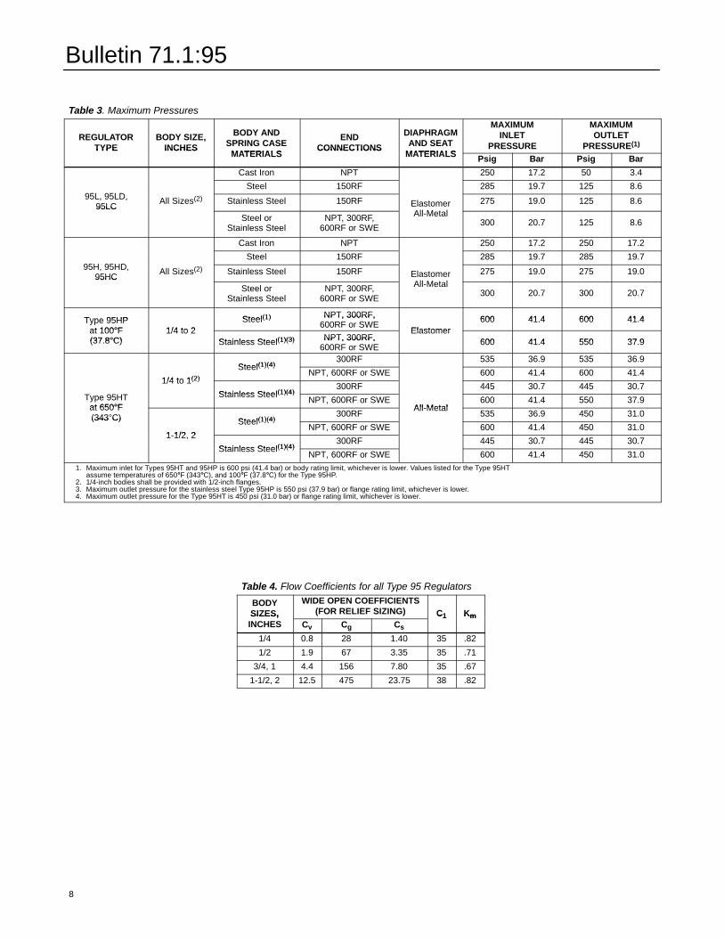
Table 3. Maximum Pressures
REGULATORTYPE
BODY SIZE,INCHES
BODY ANDSPRING CASE
MATERIALS
ENDCONNECTIONS
DIAPHRAGMAND SEAT
MATERIALS
MAXIMUMINLET
PRESSURE
MAXIMUMOUTLET
PRESSURE(1)TYPE INCHESMATERIALS
CONNECTIONSMATERIALS Psig Bar Psig Bar
Cast Iron NPT 250 17.2 50 3.4
95L, 95LD,Steel 150RF 285 19.7 125 8.6
95L, 95LD,95LC
All Sizes(2) Stainless Steel 150RF ElastomerAll-Metal
275 19.0 125 8.695LC
Steel orStainless Steel
NPT, 300RF,600RF or SWE
ElastomerAll-Metal
300 20.7 125 8.6
Cast Iron NPT 250 17.2 250 17.2
95H, 95HD,Steel 150RF 285 19.7 285 19.7
95H, 95HD,95HC
All Sizes(2) Stainless Steel 150RF ElastomerAll-Metal
275 19.0 275 19.095HC
Steel orStainless Steel
NPT, 300RF,600RF or SWE
ElastomerAll-Metal
300 20.7 300 20.7
Type 95HP Steel(1) NPT, 300RF, 600 41.4 600 41.4Type 95HPat 100°F 1/4 to 2
Steel(1) NPT, 300RF,600RF or SWE
Elastomer600 41.4 600 41.4
at 100°F(37.8°C)
1/4 to 2Stainless Steel(1)(3) NPT, 300RF,
Elastomer600 41.4 550 37.9(37.8°C) Stainless Steel(1)(3) NPT, 300RF,
600RF or SWE600 41.4 550 37.9
Steel(1)(4)300RF 535 36.9 535 36.9
1/4 to 1(2)
Steel(1)(4)NPT, 600RF or SWE 600 41.4 600 41.4
Type 95HT
1/4 to 1(2)
Stainless Steel(1)(4)300RF 445 30.7 445 30.7
Type 95HTat 650°F
Stainless Steel(1)(4)NPT, 600RF or SWE
All-Metal600 41.4 550 37.9
at 650°F(343°C) Steel(1)(4)
300RFAll-Metal
535 36.9 450 31.0(343°C)
1-1/2, 2
Steel(1)(4)NPT, 600RF or SWE 600 41.4 450 31.0
1-1/2, 2
Stainless Steel(1)(4)300RF 445 30.7 445 30.7
Stainless Steel(1)(4)NPT, 600RF or SWE 600 41.4 450 31.0
1. Maximum inlet for Types 95HT and 95HP is 600 psi (41.4 bar) or body rating limit, whichever is lower. Values listed for the Type 95HTassume temperatures of 650°°F (343°°C), and 100°°F (37.8°°C) for the Type 95HP.
8
2. 1/4-inch bodies shall be provided with 1/2-inch flanges.3. Maximum outlet pressure for the stainless steel Type 95HP is 550 psi (37.9 bar) or flange rating limit, whichever is lower.4. Maximum outlet pressure for the Type 95HT is 450 psi (31.0 bar) or flange rating limit, whichever is lower.
Table 4. Flow Coefficients for all Type 95 Regulators
BODYSIZES,
WIDE OPEN COEFFICIENTS(FOR RELIEF SIZING) C1 KmSIZES,
INCHES Cv Cg Cs
C1 Km
1/4 0.8 28 1.40 35 .82
1/2 1.9 67 3.35 35 .71
3/4, 1 4.4 156 7.80 35 .67
1-1/2, 2 12.5 475 23.75 38 .82
Bulletin 71.1:95
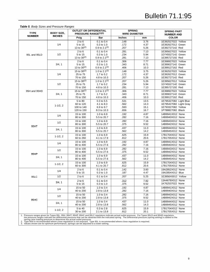
Table 5. Body Sizes and Pressure RangesTYPENUMBER
BODY SIZE,INCHES
OUTLET OR DIFFERENTIALPRESSURE RANGE(1)(3)
SPRINGWIRE DIAMETER
SPRING PARTNUMBER AND
NUMBER INCHESPsig Bar Inches mm
NUMBER ANDCOLOR
1/42 to 65 to 15
13 to 30(2)
0.1 to 0.40.3 to 1.0
0.9 to 2.1(2)
.148
.172
.207
3.764.375.26
1E392527022 Yellow1E392627012 Green1E392727142 Red
95L and 95LD 1/22 to 65 to 15
13 to 30(2)
0.1 to 0.40.3 to 1.0
0.9 to 2.1(2)
.281
.234
.281
7.135.947.13
1E395627022 Yellow1D745527142 Green1E395727192 Red
3/4, 12 to 65 to 15
13 to 30(2)
0.1 to 0.40.3 to 1.0
0.9 to 2.1(2)
.306
.343
.406
7.778.7110.3
1E398927022 Yellow1E399027142 Green1E399127162 Red
1/415 to 30(2)
25 to 7570 to 150
1.0 to 2.1(2)
1.7 to 5.24.8 to 10.3
.148
.172
.207
3.754.375.26
1E392527022 Yellow1E392627012 Green1E392727142 Red
1/215 to 30(2)
25 to 7570 to 150
1.0 to 2.1(2)
1.7 to 5.24.8 to 10.3
.207
.234
.281
5.265.947.13
1E395627012 Yellow1D745527142 Green1E395727192 Red
95H and 95HD3/4, 1
15 to 30(2)
25 to 7570 to 150
1.0 to 2.1(2)
1.7 to 5.24.8 to 10.3
.306
.343
.406
7.778.7110.3
1E398927022 Yellow1E399027142 Green1E399127162 Red
1-1/2, 2
5 to 8060 to 120
100 to 140120 to 150
0.3 to 5.54.1 to 8.36.9 to 9.78.3 to 10.3
.531
.562
.593
.656
13.514.315.116.7
1E795327082 Light Blue1E795427082 Light Gray1E793327082 Yellow1P788827082 Black
1/4 15 to 10080 to 300
1.0 to 6.95.5 to 20.7
.192
.2824.877.16
14B9941X012 None14B9940X012 None
95HT1/2 15 to 100
80 to 3001.0 to 6.95.5 to 20.7
.282
.3757.169.52
14B9943X012 None14B9942X012 None
95HT3/4, 1 15 to 100
80 to 3001.0 to 6.95.5 to 20.7
.437
.56211.014.2
14B9944X012 None14B9945X012 None
1-1/2, 2 15 to 10060 to 260
1.0 to 6.94.1 to 17.9
.625
.81215.920.6
17B1704X012 None17B1705X012 None
1/4 15 to 10080 to 400
1.0 to 6.95.5 to 27.6
.192
.2824.877.16
14B9941X012 None14B9940X012 None
95HP1/2 15 to 100
80 to 4001.0 to 6.95.5 to 27.6
.282
.3757.169.52
14B9943X012 None14B9942X012 None
95HP3/4, 1 15 to 100
80 to 4001.0 to 6.95.5 to 27.6
.437
.56211.014.2
14B9944X012 None14B9945X012 None
1-1/2, 2 15 to 10060 to 300
1.0 to 6.94.1 to 20.7
.625
.81215.920.6
17B1704X012 None17B1705X012 None
1/4 2 to 65 to 15
0.1 to 0.40.3 to 1.0
.142
.1873.604.47
19A2852X012 None19A2854X012 Blue
95LC 1/2 2 to 6 0.1 to 0.4 .207 5.25 1E3956X0012 Yellow95LC
3/4, 12 to 65 to 15
0.1 to 0.40.3 to 1.0
.312
.3757.929.52
13A4678X012 None1K762537022 None3/4, 1
2 to 65 to 15
0.1 to 0.40.3 to 1.0
.312
.3757.929.52
13A4678X012 None1K762537022 None
1/4 15 to 5040 to 200
1.0 to 3.42.8 to 13.8
.192
.2824.877.16
14B9941X012 None14B9940X012 None
95HC1/2 15 to 50
40 to 2001.0 to 3.42.8 to 13.8
.282
.3757.169.52
14B9943X012 None14B9942X012 None
95HC3/4, 1 15 to 50
40 to 2001.0 to 3.42.8 to 13.8
.437
.56211.014.3
14B9944X012 None14B9945X012 None
1-1/2, 2 5 to 4030 to 200
0.3 to 2.82.1 to 13.8
.625
.81215.920.1
17B1704X012 None17B1705X012 None
1. Pressure ranges given for Types 95L, 95H, 95HT, 95HP, 95HC and 95LC regulators indicate actual outlet pressure. For Types 95LD and 95HD regulators,the pressure ranges indicate the differential pressure that can be obtained with the indicated spring. The differential pressure (spring setting) is added to thespring case loading pressure to determine the actual outlet pressure.
2. Type 95H is recommended where close regulation is not required. Type 95L is recommended where close regulation is required.
9
3. Values shown are for optimum performance, springs can be adjusted to a lower setting.
Bulletin 71.1:95
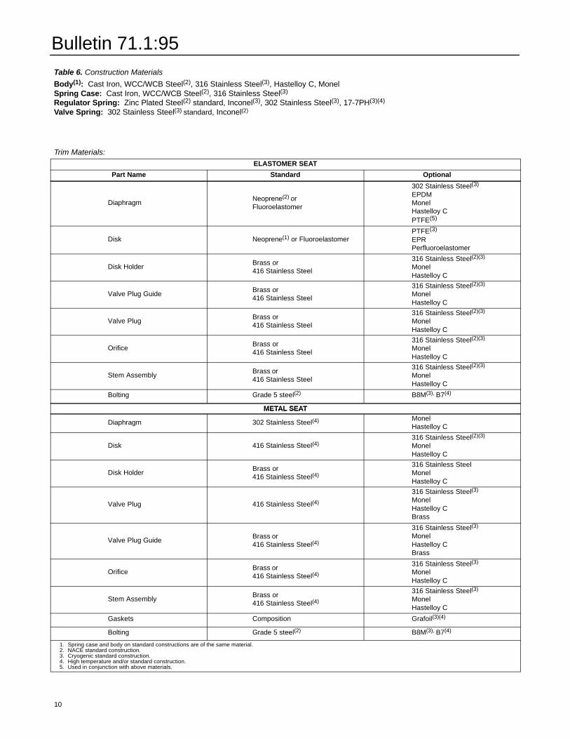
Table 6. Construction MaterialsBody(1): Cast Iron, WCC/WCB Steel(2), 316 Stainless Steel(3), Hastelloy C, MonelSpring Case: Cast Iron, WCC/WCB Steel(2), 316 Stainless Steel(3)
Regulator Spring: Zinc Plated Steel(2) standard, Inconel(3), 302 Stainless Steel(3), 17-7PH(3)(4)
Valve Spring: 302 Stainless Steel(3) standard, Inconel(2)
Trim Materials:ELASTOMER SEAT
Part Name Standard Optional
Diaphragm Neoprene(2) orFluoroelastomer
302 Stainless Steel(3)
EPDMMonelHastelloy CPTFE(5)
Disk Neoprene(1) or FluoroelastomerPTFE(3)
EPRPerfluoroelastomer
Disk Holder Brass or416 Stainless Steel
316 Stainless Steel(2)(3)
MonelHastelloy C
Valve Plug Guide Brass or416 Stainless Steel
316 Stainless Steel(2)(3)
MonelHastelloy C
Valve Plug Brass or416 Stainless Steel
316 Stainless Steel(2)(3)
MonelHastelloy C
Orifice Brass or416 Stainless Steel
316 Stainless Steel(2)(3)
MonelHastelloy C
Stem Assembly Brass or416 Stainless Steel
316 Stainless Steel(2)(3)
MonelHastelloy C
Bolting Grade 5 steel(2) B8M(3), B7(4)
METAL SEATMETAL SEATMETAL SEAT
Diaphragm 302 Stainless Steel(4) MonelHastelloy C
Disk 416 Stainless Steel(4)316 Stainless Steel(2)(3)
MonelHastelloy C
Disk Holder Brass or416 Stainless Steel(4)
316 Stainless SteelMonelHastelloy C
Valve Plug 416 Stainless Steel(4)
316 Stainless Steel(3)
MonelHastelloy CBrass
Valve Plug Guide Brass or416 Stainless Steel(4)
316 Stainless Steel(3)
MonelHastelloy CBrass
Orifice Brass or416 Stainless Steel(4)
316 Stainless Steel(3)
MonelHastelloy C
Stem Assembly Brass or416 Stainless Steel(4)
316 Stainless Steel(3)
MonelHastelloy C
Gaskets Composition Grafoil(3)(4)
Bolting Grade 5 steel(2) B8M(3), B7(4)
10
1. Spring case and body on standard constructions are of the same material.2. NACE standard construction.3. Cryogenic standard construction.4. High temperature and/or standard construction.5. Used in conjunction with above materials.
Bulletin 71.1:95
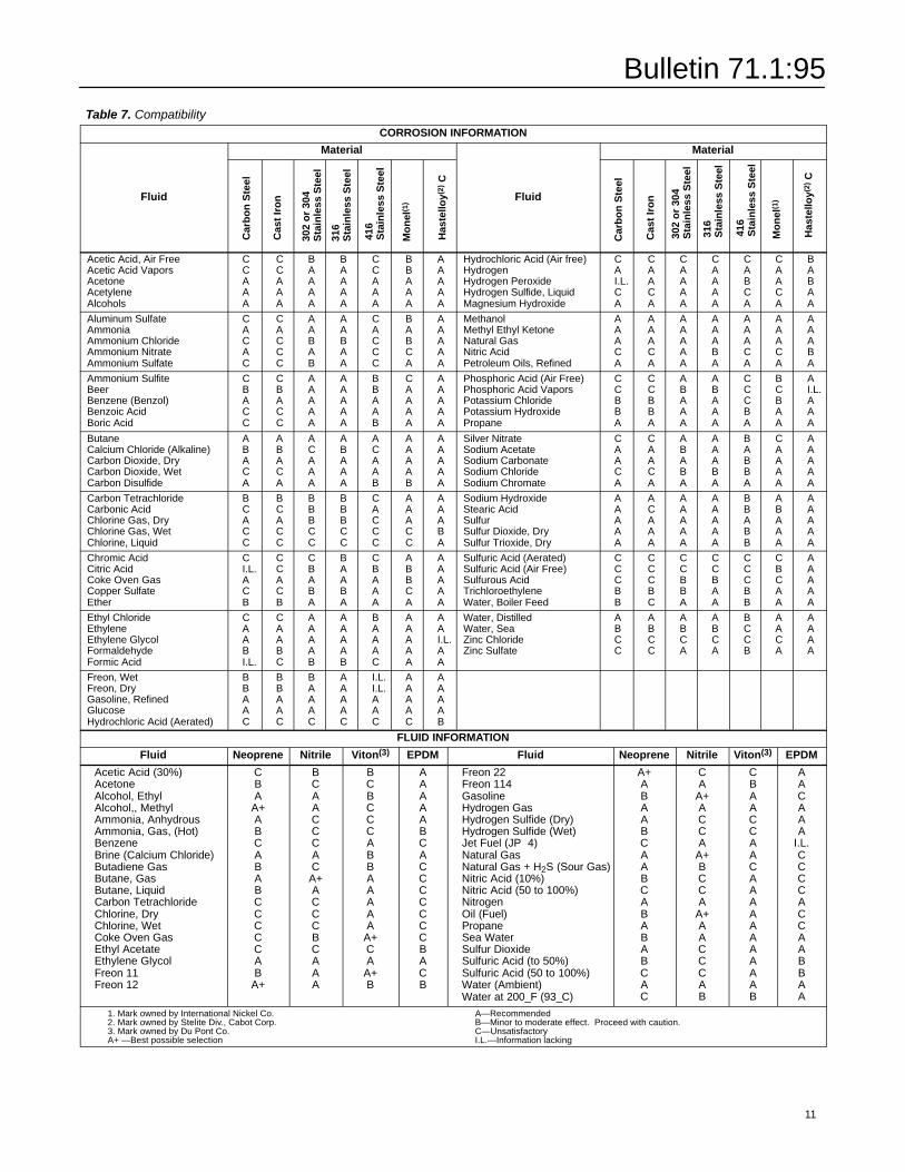
Table 7. CompatibilityCORROSION IN
Material
Fluid
Car
bo
nS
teel
Cas
tIr
on
302
or
304
Sta
inle
ssS
teel
316
Sta
inle
ssS
teel
416
Sta
inle
ssS
teel
Mo
nel
(1)
Has
tello
y(2)
C
Acetic Acid, Air FreeAcetic Acid VaporsAcetoneAcetyleneAlcohols
CCAAA
CCAAA
BAAAA
BAAAA
CCAAA
BBAAA
AAAAA
Aluminum SulfateAmmoniaAmmonium ChlorideAmmonium NitrateAmmonium Sulfate
CACAC
CACCC
AABAB
AABAA
CACCC
BABCA
AAAAA
Ammonium SulfiteBeerBenzene (Benzol)Benzoic AcidBoric Acid
CBACC
CBACC
AAAAA
AAAAA
BBAAB
CAAAA
AAAAA
ButaneCalcium Chloride (Alkaline)Carbon Dioxide, DryCarbon Dioxide, WetCarbon Disulfide
ABACA
ABACA
ACAAA
ABAAA
ACAAB
AAAAB
AAAAA
Carbon TetrachlorideCarbonic AcidChlorine Gas, DryChlorine Gas, WetChlorine, Liquid
BCACC
BCACC
BBBCC
BBBCC
CACCC
AAACC
AAABA
Chromic AcidCitric AcidCoke Oven GasCopper SulfateEther
CI.L.ACB
CCACB
CBABA
BAABA
CBAAA
ABBCA
AAAAA
Ethyl ChlorideEthyleneEthylene GlycolFormaldehydeFormic Acid
CAABI.L.
CAABC
AAAAB
AAAAB
BAAAC
AAAAA
AAI.L.AA
Freon, WetFreon, DryGasoline, RefinedGlucoseHydrochloric Acid (Aerated)
BBAAC
BBAAC
BAAAC
AAAAC
I.L.I.L.AAC
AAAAC
AAAAB
FORMATION
Material
Fluid
Car
bo
nS
teel
Cas
tIr
on
302
or
304
Sta
inle
ssS
teel
316
Sta
inle
ssS
teel
416
Sta
inle
ssS
teel
Mo
nel
(1)
Has
tello
y(2)
C
Hydrochloric Acid (Air free)HydrogenHydrogen PeroxideHydrogen Sulfide, LiquidMagnesium Hydroxide
CAI.L.CA
CAACA
CAAAA
CAAAA
CABCA
CAACA
BABAA
MethanolMethyl Ethyl KetoneNatural GasNitric AcidPetroleum Oils, Refined
AAACA
AAACA
AAAAA
AAABA
AAACA
AAACA
AAABA
Phosphoric Acid (Air Free)Phosphoric Acid VaporsPotassium ChloridePotassium HydroxidePropane
CCBBA
CCBBA
ABAAA
ABAAA
CCCBA
BCBAA
AI.L.AAA
Silver NitrateSodium AcetateSodium CarbonateSodium ChlorideSodium Chromate
CAACA
CAACA
ABABA
AAABA
BABBA
CAAAA
AAAAA
Sodium HydroxideStearic AcidSulfurSulfur Dioxide, DrySulfur Trioxide, Dry
AAAAA
ACAAA
AAAAA
AAAAA
BBABB
ABAAA
AAAAA
Sulfuric Acid (Aerated)Sulfuric Acid (Air Free)Sulfurous AcidTrichloroethyleneWater, Boiler Feed
CCCBB
CCCBC
CCBBA
CCBAA
CCCBB
CBCAA
AAAAA
Water, DistilledWater, SeaZinc ChlorideZinc Sulfate
ABCC
ABCC
ABCA
ABCA
BCCB
AACA
AAAA
FLUID INFORMATION
Fluid Neoprene Nitrile Viton(3) EPDM Fluid Neoprene Nitrile Viton(3) EPDM
Acetic Acid (30%)AcetoneAlcohol, EthylAlcohol,, MethylAmmonia, AnhydrousAmmonia, Gas, (Hot)BenzeneBrine (Calcium Chloride)Butadiene GasButane, GasButane, LiquidCarbon TetrachlorideChlorine, DryChlorine, WetCoke Oven GasEthyl AcetateEthylene GlycolFreon 11Freon 12
CBA
A+ABCABABCCCCCAB
A+
BCAACCCACA+ACCCBCAAA
BCBCCCABBAAAAA
A+CA
A+B
AAAAABCACCCCCCCBACB
Freon 22Freon 114GasolineHydrogen GasHydrogen Sulfide (Dry)Hydrogen Sulfide (Wet)Jet Fuel (JP�4)Natural GasNatural Gas + H2S (Sour Gas)Nitric Acid (10%)Nitric Acid (50 to 100%)NitrogenOil (Fuel)PropaneSea WaterSulfur DioxideSulfuric Acid (to 50%)Sulfuric Acid (50 to 100%)Water (Ambient)Water at 200_F (93_C)
A+ABAABCAABCABABABCAC
CA
A+ACCA
A+BCCA
A+AACCCAB
CBAACCAACAAAAAAAAAAB
AACAAA
I.L.CCCCACCAABBAA
1. Mark owned by International Nickel Co. A—Recommended2. Mark owned by Stelite Div., Cabot Corp. B—Minor to moderate effect. Proceed with caution.3. Mark owned by Du Pont Co. C—UnsatisfactoryA+ —Best possible selection I.L.—Information lacking
11
Bulletin 71.1:95
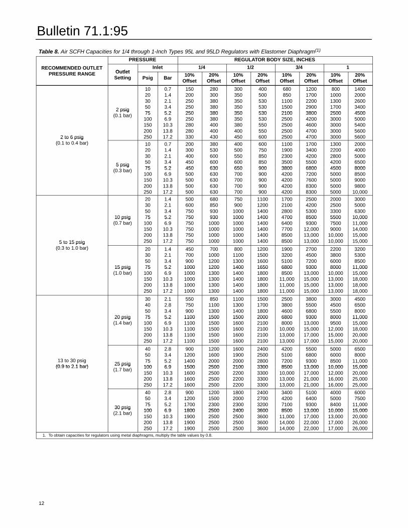
Table 8. Air SCFH Capacities for 1/4 through 1-Inch Types 95L and 95LD Regulators with Elastomer Diaphragm(1)PRESSURE REGULATOR BODY SIZE, INCHES
RECOMMENDED OUTLETPRESSURE RANGE Outlet
Inlet 1/4 1/2 3/4 1RECOMMENDED OUTLETPRESSURE RANGE Outlet
Setting Psig Bar 10%Offset
20%Offset
10%Offset
20%Offset
10%Offset
20%Offset
10%Offset
20%Offset
2 psig(0.1 bar)
1020305075
0.71.42.13.45.2
150200250250250
280300380380380
300350350350350
400500530530530
680850
110015002100
12001700220029003800
8001000130017002500
14002000260034004500
2 to 6 psig(0.1 to 0.4 bar)
2 psig(0.1 bar) 75
100150200250
5.26.9
10.313.817.2
250250280280330
380380400400430
350350380400450
530530550550600
21002500250025002500
38004200460047004700
25003000300030003000
450050005400560056002 to 6 psig
(0.1 to 0.4 bar)
5 psig(0.3 bar)
1020305075
0.71.42.13.45.2
200300400450450
380530600600630
400500550600650
600750850850900
11001900230035003800
17003400420055006800
13002200280042004500
20004000500065008000
5 psig(0.3 bar) 75
100150200250
5.26.9
10.313.817.2
450500500500500
630630630630630
650700700700700
900900900900900
38004200420042004200
68007200760083008300
45005000500050005000
8000850090009800
10,000
10 psig(0.7 bar)
20305075
1.42.13.45.2
500600750750
680850930930
750900
10001000
1100120014001400
1700210028004700
2500420053008500
2000250033005500
300050006300
10,000
5 to 15 psig(0.3 to 1.0 bar)
10 psig(0.7 bar)
75100150200250
5.26.9
10.313.817.2
750750750750750
9301000100010001000
10001000100010001000
14001400140014001400
47006400770085008500
85009300
12,00013,00013,000
550075009000
10,00010,000
10,00011,00014,00015,00015,0005 to 15 psig
(0.3 to 1.0 bar)
15 psig(1.0 bar)
20305075
1.42.13.45.2
450700900
1000
700100012001200
800110013001400
1200150016001650
1900320051006800
2700450072009300
2200380060008000
320053008500
11,00015 psig(1.0 bar)
75100150200250
5.26.9
10.313.817.2
10001000100010001000
12001300130013001300
14001400140014001400
16501800180018001800
68008500
11,00011,00011,000
930013,00015,00015,00015,000
800010,00013,00013,00013,000
11,00015,00018,00018,00018,000
20 psig(1.4 bar)
30405075
2.12.83.45.2
550750900
1100
850110013001500
1100130014001500
1500170018002000
2500380046006800
3800550068009300
3000450055008000
450065008000
11,00020 psig(1.4 bar)
75100150200250
5.26.9
10.313.817.2
11001100110011001100
15001500150015001500
15001600160016001600
20002100210021002100
68008000
10,00013,00013,000
930013,00015,00017,00017,000
80009500
12,00015,00015,000
11,00015,00018,00020,00020,000
13 to 30 psig(0.9 to 2.1 bar) 25 psig
(1.7 bar)
405075100
2.83.45.26.9
900120014001500
1200160020002500
1600190020002100
2400250028003300
4200510072008500
550068009300
13,000
500060008500
10,000
65008000
11,00015,000(0.9 to 2.1 bar) 25 psig
(1.7 bar) 100150200250
6.910.313.817.2
1500160016001600
2500250025002500
2100220022002200
3300330033003300
850010,00013,00013,000
13,00017,00021,00021,000
10,00012,00016,00016,000
15,00020,00025,00025,000
30 psig(2.1 bar)
405075100
2.83.45.26.9
900120017001800
1200150023002500
1800200023002400
2400270032003600
3400420071008500
510064009300
13,000
400050008400
10,000
60007500
11,00015,000
30 psig(2.1 bar) 100
150200250
6.910.313.817.2
1800190019001900
2500250025002500
2400250025002500
3600360036003600
850011,00014,00014,000
13,00017,00022,00022,000
10,00013,00017,00017,000
15,00020,00026,00026,000
1. To obtain capacities for regulators using metal diaphragms, multiply the table values by 0.8.
12
Bulletin 71.1:95
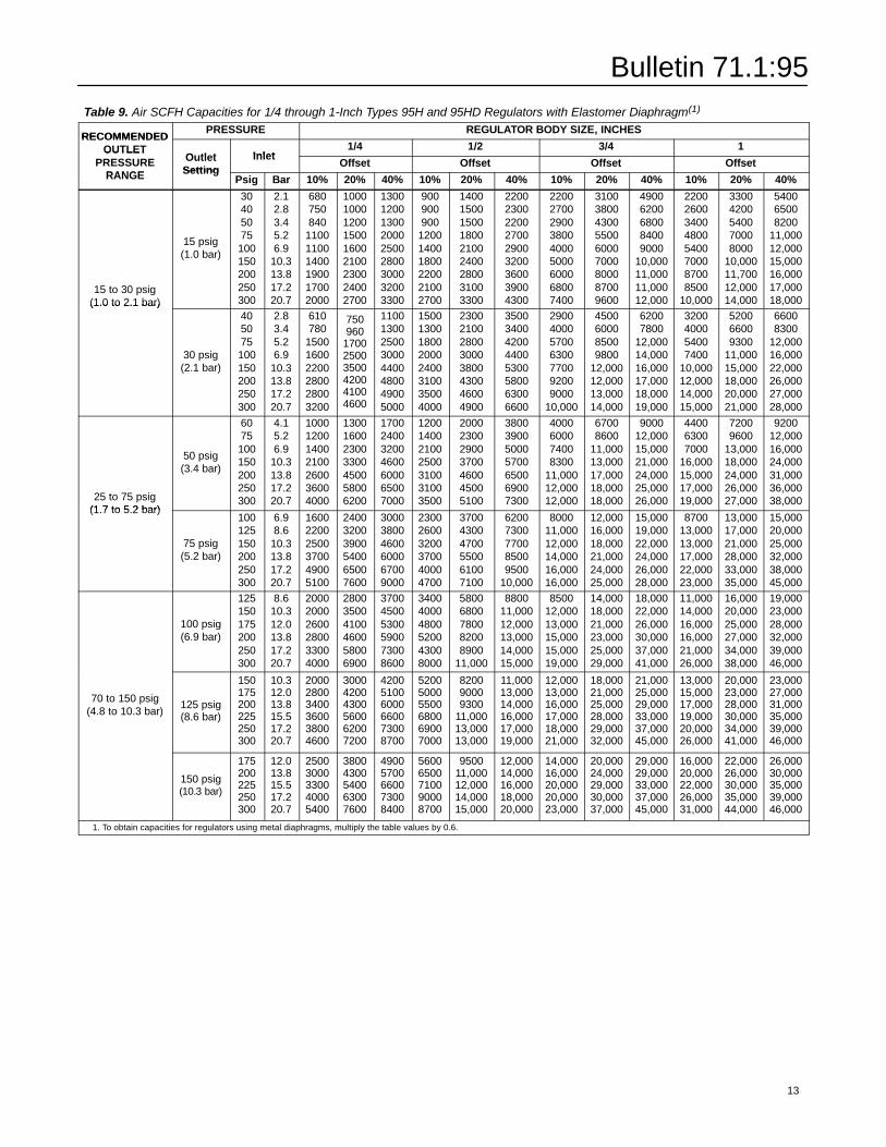
Table 9. Air SCFH Capacities for 1/4 through 1-Inch Types 95H and 95HD Regulators with Elastomer Diaphragm(1)RECOMMENDEDPRESSURE REGULATOR BODY SIZE, INCHES
RECOMMENDEDOUTLET
Outlet Inlet1/4 1/2 3/4 1OUTLET
PRESSURERANGE
OutletSetting
InletOffset Offset Offset OffsetPRESSURE
RANGE SettingPsig Bar 10% 20% 40% 10% 20% 40% 10% 20% 40% 10% 20% 40%
15 to 30 psig(1.0 to 2.1 bar)
15 psig(1.0 bar)
30405075100150200250300
2.12.83.45.26.9
10.313.817.220.7
680750840
110011001400190017002000
100010001200150016002100230024002700
130012001300200025002800300032003300
900900900
120014001800220021002700
140015001500180021002400280031003300
220023002200270029003200360039004300
220027002900380040005000600068007400
310038004300550060007000800087009600
49006200680084009000
10,00011,00011,00012,000
22002600340048005400700087008500
10,000
33004200540070008000
10,00011,70012,00014,000
540065008200
11,00012,00015,00016,00017,00018,000(1.0 to 2.1 bar)
30 psig(2.1 bar)
405075100150200250300
2.83.45.26.9
10.313.817.220.7
610780
150016002200280028003200
750960
170025003500420041004600
11001300250030004400480049005000
15001300180020002400310035004000
23002100280030003800430046004900
35003400420044005300580063006600
2900400057006300770092009000
10,000
4500600085009800
12,00012,00013,00014,000
62007800
12,00014,00016,00017,00018,00019,000
3200400054007400
10,00012,00014,00015,000
520066009300
11,00015,00018,00020,00021,000
66008300
12,00016,00022,00026,00027,00028,000
25 to 75 psig(1.7 to 5.2 bar)
50 psig(3.4 bar)
6075100150200250300
4.15.26.9
10.313.817.220.7
1000120014002100260036004000
1300160023003300450058006200
1700240032004600600065007000
1200140021002500310031003500
2000230029003700460045005100
3800390050005700650069007300
4000600074008300
11,00012,00012,000
67008600
11,00013,00017,00018,00018,000
900012,00015,00021,00024,00025,00026,000
440063007000
16,00015,00017,00019,000
72009600
13,00018,00024,00026,00027,000
920012,00016,00024,00031,00036,00038,000
(1.7 to 5.2 bar)
75 psig(5.2 bar)
100125150200250300
6.98.6
10.313.817.220.7
160022002500370049005100
240032003900540065007600
300038004600600067009000
230026003200370040004700
370043004700550061007100
62007300770085009500
10,000
800011,00012,00014,00016,00016,000
12,00016,00018,00021,00024,00025,000
15,00019,00022,00024,00026,00028,000
870013,00013,00017,00022,00023,000
13,00017,00021,00028,00033,00035,000
15,00020,00025,00032,00038,00045,000
100 psig(6.9 bar)
125150175200250300
8.610.312.013.817.220.7
200020002600280033004000
280035004100460058006900
370045005300590073008600
340040004800520043008000
58006800780082008900
11,000
880011,00012,00013,00014,00015,000
850012,00013,00015,00015,00019,000
14,00018,00021,00023,00025,00029,000
18,00022,00026,00030,00037,00041,000
11,00014,00016,00016,00021,00026,000
16,00020,00025,00027,00034,00038,000
19,00023,00028,00032,00039,00046,000
70 to 150 psig(4.8 to 10.3 bar)
125 psig(8.6 bar)
150175200225250300
10.312.013.815.517.220.7
200028003400360038004600
300042004300560062007200
420051006000660073008700
520050005500680069007000
820090009300
11,00013,00013,000
11,00013,00014,00016,00017,00019,000
12,00013,00016,00017,00018,00021,000
18,00021,00025,00028,00029,00032,000
21,00025,00029,00033,00037,00045,000
13,00015,00017,00019,00020,00026,000
20,00023,00028,00030,00034,00041,000
23,00027,00031,00035,00039,00046,000
150 psig(10.3 bar)
175200225250300
12.013.815.517.220.7
25003000330040005400
38004300540063007600
49005700660073008400
56006500710090008700
950011,00012,00014,00015,000
12,00014,00016,00018,00020,000
14,00016,00020,00020,00023,000
20,00024,00029,00030,00037,000
29,00029,00033,00037,00045,000
16,00020,00022,00026,00031,000
22,00026,00030,00035,00044,000
26,00030,00035,00039,00046,000
1. To obtain capacities for regulators using metal diaphragms, multiply the table values by 0.6.
13
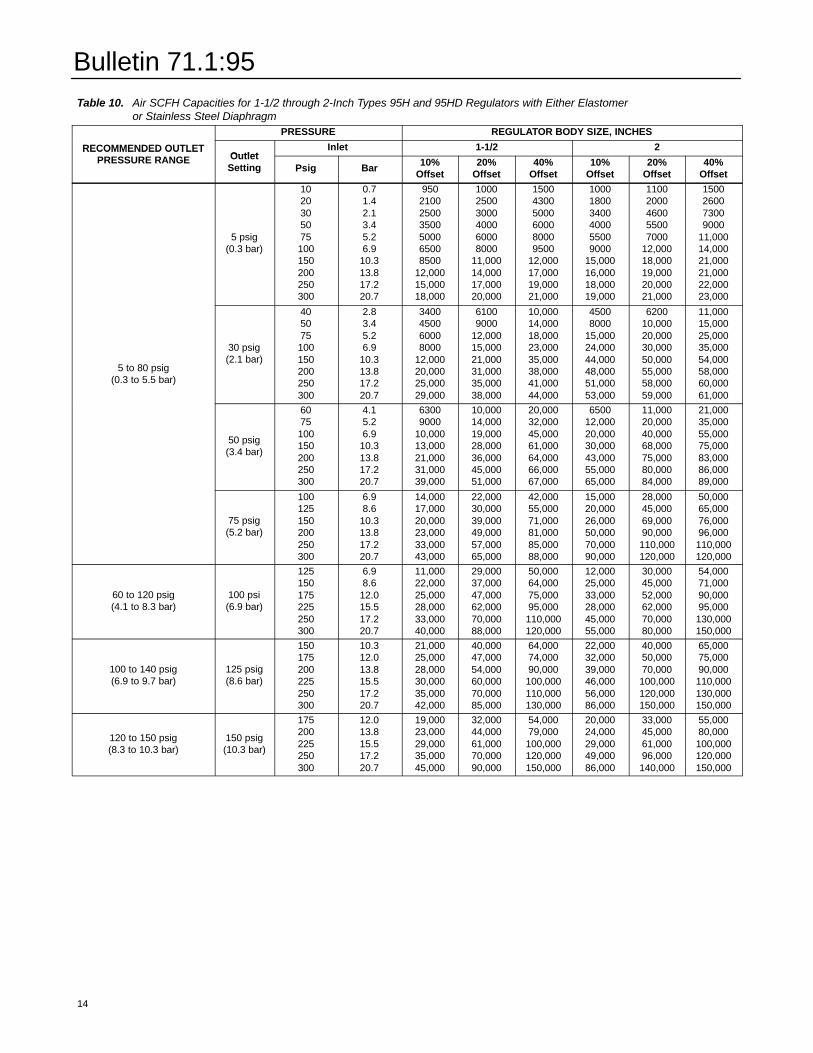
Bulletin 71.1:95
Table 10. Air SCFH Capacities for 1-1/2 through 2-Inch Types 95H and 95HD Regulators with Either Elastomeror Stainless Steel DiaphragmPRESSURE REGULATOR BODY SIZE, INCHES
RECOMMENDED OUTLETPRESSURE RANGE Outlet
Inlet 1-1/2 2RECOMMENDED OUTLETPRESSURE RANGE Outlet
Setting Psig Bar 10%Offset
20%Offset
40%Offset
10%Offset
20%Offset
40%Offset
5 psig(0.3 bar)
1020305075100150200250300
0.71.42.13.45.26.9
10.313.817.220.7
950210025003500500065008500
12,00015,00018,000
100025003000400060008000
11,00014,00017,00020,000
150043005000600080009500
12,00017,00019,00021,000
100018003400400055009000
15,00016,00018,00019,000
11002000460055007000
12,00018,00019,00020,00021,000
1500260073009000
11,00014,00021,00021,00022,00023,000
5 to 80 psig(0.3 to 5.5 bar)
30 psig(2.1 bar)
405075100150200250300
2.83.45.26.9
10.313.817.220.7
3400450060008000
12,00020,00025,00029,000
61009000
12,00015,00021,00031,00035,00038,000
10,00014,00018,00023,00035,00038,00041,00044,000
45008000
15,00024,00044,00048,00051,00053,000
620010,00020,00030,00050,00055,00058,00059,000
11,00015,00025,00035,00054,00058,00060,00061,000
50 psig(3.4 bar)
6075100150200250300
4.15.26.9
10.313.817.220.7
63009000
10,00013,00021,00031,00039,000
10,00014,00019,00028,00036,00045,00051,000
20,00032,00045,00061,00064,00066,00067,000
650012,00020,00030,00043,00055,00065,000
11,00020,00040,00068,00075,00080,00084,000
21,00035,00055,00075,00083,00086,00089,000
75 psig(5.2 bar)
100125150200250300
6.98.6
10.313.817.220.7
14,00017,00020,00023,00033,00043,000
22,00030,00039,00049,00057,00065,000
42,00055,00071,00081,00085,00088,000
15,00020,00026,00050,00070,00090,000
28,00045,00069,00090,000110,000120,000
50,00065,00076,00096,000110,000120,000
60 to 120 psig(4.1 to 8.3 bar)
100 psi(6.9 bar)
125150175225250300
6.98.6
12.015.517.220.7
11,00022,00025,00028,00033,00040,000
29,00037,00047,00062,00070,00088,000
50,00064,00075,00095,000110,000120,000
12,00025,00033,00028,00045,00055,000
30,00045,00052,00062,00070,00080,000
54,00071,00090,00095,000130,000150,000
100 to 140 psig(6.9 to 9.7 bar)
125 psig(8.6 bar)
150175200225250300
10.312.013.815.517.220.7
21,00025,00028,00030,00035,00042,000
40,00047,00054,00060,00070,00085,000
64,00074,00090,000100,000110,000130,000
22,00032,00039,00046,00056,00086,000
40,00050,00070,000100,000120,000150,000
65,00075,00090,000110,000130,000150,000
120 to 150 psig(8.3 to 10.3 bar)
150 psig(10.3 bar)
175200225250300
12.013.815.517.220.7
19,00023,00029,00035,00045,000
32,00044,00061,00070,00090,000
54,00079,000100,000120,000150,000
20,00024,00029,00049,00086,000
33,00045,00061,00096,000140,000
55,00080,000100,000120,000150,000
14
Bulletin 71.1:95
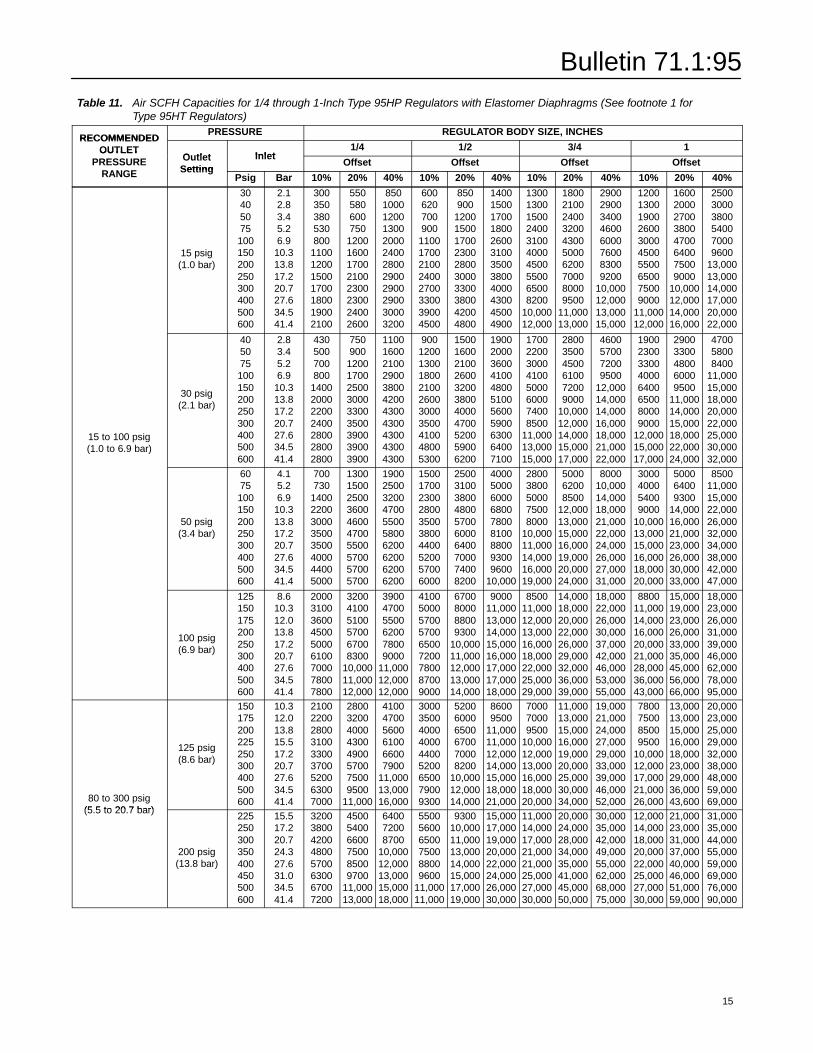
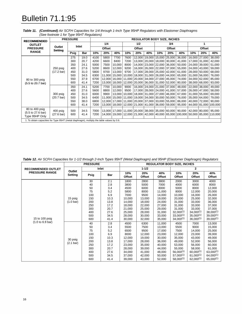
Table 11. Air SCFH Capacities for 1/4 through 1-Inch Type 95HP Regulators with Elastomer Diaphragms (See footnote 1 forType 95HT Regulators)
RECOMMENDEDPRESSURE REGULATOR BODY SIZE, INCHES
RECOMMENDEDOUTLET
Outlet Inlet1/4 1/2 3/4 1OUTLET
PRESSURERANGE
OutletSetting
InletOffset Offset Offset OffsetPRESSURE
RANGE SettingPsig Bar 10% 20% 40% 10% 20% 40% 10% 20% 40% 10% 20% 40%
15 psig(1.0 bar)
30405075100150200250300400500600
2.12.83.45.26.9
10.313.817.220.727.634.541.4
300350380530800
1100120015001700180019002100
550580600750
12001600170021002300230024002600
85010001200130020002400280029002900290030003200
600620700900
11001700210024002700330039004500
850900
1200150017002300280030003300380042004800
140015001700180026003100350038004000430045004900
1300130015002400310040004500550065008200
10,00012,000
1800210024003200430050006200700080009500
11,00013,000
29002900340046006000760083009200
10,00012,00013,00015,000
1200130019002600300045005500650075009000
11,00012,000
16002000270038004700640075009000
10,00012,00014,00016,000
250030003800540070009600
13,00013,00014,00017,00020,00022,000
15 to 100 psig(1.0 to 6.9 bar)
30 psig(2.1 bar)
405075100150200250300400500600
2.83.45.26.9
10.313.817.220.727.634.541.4
430500700800
1400200022002400280028002800
750900
120017002500300033003500390039003900
11001600210029003800420043004300430043004300
9001200130018002100260030003500410048005300
15001600210026003200380040004700520059006200
19002000360041004800510056005900630064007100
17002200300041005000600074008500
11,00013,00015,000
280035004500610072009000
10,00012,00014,00015,00017,000
4600570072009500
12,00014,00014,00016,00018,00021,00022,000
19002300330040006400650080009000
12,00015,00017,000
29003300480060009500
11,00014,00015,00018,00022,00024,000
470058008400
11,00015,00018,00020,00022,00025,00030,00032,000
50 psig(3.4 bar)
6075100150200250300400500600
4.15.26.9
10.313.817.220.727.634.541.4
700730
14002200300035003500400044005000
1300150025003600460047005500570057005700
1900250032004700550058006200620062006200
1500170023002800350038004400520057006000
2500310038004800570060006400700074008200
400050006000680078008100880093009600
10,000
28003800500075008000
10,00011,00014,00016,00019,000
500062008500
12,00013,00015,00016,00019,00020,00024,000
800010,00014,00018,00021,00022,00024,00026,00027,00031,000
3000400054009000
10,00013,00015,00016,00018,00020,000
500064009300
14,00016,00021,00023,00026,00030,00033,000
850011,00015,00022,00026,00032,00034,00038,00042,00047,000
100 psig(6.9 bar)
125150175200250300400500600
8.610.312.013.817.220.727.634.541.4
200031003600450050006100700078007800
320041005100570067008300
10,00011,00012,000
390047005500620078009000
11,00012,00012,000
410050005700570065007200780087009000
6700800088009300
10,00011,00012,00013,00014,000
900011,00013,00014,00015,00016,00017,00017,00018,000
850011,00012,00013,00016,00018,00022,00025,00029,000
14,00018,00020,00022,00026,00029,00032,00036,00039,000
18,00022,00026,00030,00037,00042,00046,00053,00055,000
880011,00014,00016,00020,00021,00028,00036,00043,000
15,00019,00023,00026,00033,00035,00045,00056,00066,000
18,00023,00026,00031,00039,00046,00062,00078,00095,000
80 to 300 psig(5.5 to 20.7 bar)
125 psig(8.6 bar)
150175200225250300400500600
10.312.013.815.517.220.727.634.541.4
210022002800310033003700520063007000
28003200400043004900570075009500
11,000
410047005600610066007900
11,00013,00016,000
300035004000400044005200650079009300
520060006500670070008200
10,00012,00014,000
86009500
11,00011,00012,00014,00015,00018,00021,000
700070009500
10,00012,00013,00016,00018,00020,000
11,00013,00015,00016,00019,00020,00025,00030,00034,000
19,00021,00024,00027,00029,00033,00039,00046,00052,000
7800750085009500
10,00012,00017,00021,00026,000
13,00013,00015,00016,00018,00023,00029,00036,00043,600
20,00023,00025,00029,00032,00038,00048,00059,00069,000
(5.5 to 20.7 bar)
200 psig(13.8 bar)
225250300350400450500600
15.517.220.724.327.631.034.541.4
32003800420048005700630067007200
450054006600750085009700
11,00013,000
640072008700
10,00012,00013,00015,00018,000
550056006500750088009600
11,00011,000
930010,00011,00013,00014,00015,00017,00019,000
15,00017,00019,00020,00022,00024,00026,00030,000
11,00014,00017,00021,00021,00025,00027,00030,000
20,00024,00028,00034,00035,00041,00045,00050,000
30,00035,00042,00049,00055,00062,00068,00075,000
12,00014,00018,00020,00022,00025,00027,00030,000
21,00023,00031,00037,00040,00046,00051,00059,000
31,00035,00044,00055,00059,00069,00076,00090,000
15
Bulletin 71.1:95
Table 11. (Continued) Air SCFH Capacities for 1/4 through 1-Inch Type 95HP Regulators with Elastomer Diaphragms(See footnote 1 for Type 95HT Regulators)
RECOMMENDEDPRESSURE REGULATOR BODY SIZE, INCHES
RECOMMENDEDOUTLET
Outlet Inlet1/4 1/2 3/4 1OUTLET
PRESSURERANGE
OutletSetting
InletOffset Offset Offset OffsetPRESSURE
RANGE SettingPsig Bar 10% 20% 40% 10% 20% 40% 10% 20% 40% 10% 20% 40%
80 to 300 psig(5.5 to 20.7 bar)
250 psig(17.2 bar)
275300350400450500550600
19.020.724.127.631.034.537.941.4
41004200500052005800630067007200
58006600750086009700
11,00012,00013,000
77008400
10,00012,00013,00015,00016,00018,000
76007200800092009700
10,00011,00012,000
12,00013,00014,00016,00017,00018,00020,00020,000
19,00020,00023,00026,00028,00031,00034,00036,000
15,00018,00022,00022,00025,00026,00027,00031,000
25,00030,00036,00037,00042,00044,00045,00052,000
36,00041,00050,00055,00061,00065,00074,00080,000
16,00017,00024,00024,00028,00031,00034,00038,000
27,00031,00039,00043,00050,00056,00062,00068,000
38,00042,00051,00059,00068,00076,00085,00093,000(5.5 to 20.7 bar)
300 psig(20.7 bar)
350400450500550600
24.127.631.034.538.041.4
520056006000640068007200
770088009900
11,00012,00013,000
10,00012,00013,00015,00017,00018,000
90009500
10,00011,00011,00012,000
16,00017,00018,00019,00020,00021,000
24,00028,00031,00034,00037,00041,000
21,00024,00027,00030,00033,00036,000
37,00041,00046,00050,00055,00059,000
48,00057,00067,00076,00086,00095,000
22,00026,00031,00035,00040,00044,000
38,00047,00055,00064,00072,00081,000
49,00058,00069,00079,00090,000
100,00080 to 400 psig
(5.5 to 27.6 bar)Type 95HP Only
400 psig(27.6 bar)
500600
34.541.4
70007200
13,00014,000
17,00019,000
11,00012,000
20,00021,000
38,00042,000
35,00040,000
60,00065,000
90,000100,000
42,00050,000
80,00085,000
95,000110,000
1. To obtain capacities for Type 95HT (metal diaphragm), multiply the table values by 0.6.
Table 12. Air SCFH Capacities for 1-1/2 through 2-Inch Types 95HT (Metal Diaphragm) and 95HP (Elastomer Diaphragm) RegulatorsPRESSURE REGULATOR BODY SIZE, INCHES
RECOMMENDED OUTLETPRESSURE RANGE Outlet
Inlet 1-1/2 2RECOMMENDED OUTLETPRESSURE RANGE Outlet
Setting Psig Bar 10%Offset
20%Offset
40%Offset
10%Offset
20%Offset
40%Offset
15 to 100 psig(1.0 to 6.9 bar)
15 psig(1.0 bar)
30405075100150200250300400500600
2.12.83.45.26.9
10.313.817.220.727.634.541.4
18003800450058007000
10,00014,00018,00021,00025,00028,00030,000
28005000600080009500
13,00018,00022,00025,00028,00030,00032,000
380070008000
11,00014,00019,00024,00027,00029,00031,00033,00035,000
2000400050008000
10,00020,00031,00031,00031,000
32,000(1)
33,000(1)
34,000(1)
300060008000
12,00016,00025,00033,00033,00033,000
34,000(1)
35,000(1)
36,000(1)
40008000
12,00020,00026,00032,00036,00037,00037,000
38,000(1)
39,000(1)
39,000(1)15 to 100 psig(1.0 to 6.9 bar)
30 psig(2.1 bar)
405075100150200250300400500600
2.83.45.26.9
10.313.817.220.727.634.541.4
4500550065008000
12,00017,00023,00028,00034,00037,00039,000
630075009500
12,00019,00028,00035,00039,00041,00042,00043,000
11,00013,00017,00023,00030,00036,00040,00044,00048,00050,00052,000
450055007500
12,00035,00049,00053,00055,000
56,000(1)
57,000(1)
58,000(1)
70009000
14,00023,00043,00052,00056,00058,000
60,000(1)
61,000(1)
62,000(1)
13,00015,00025,00039,00049,00056,00060,00061,000
63,000(1)
64,000(1)
65,000(1)
16
Bulletin 71.1:95
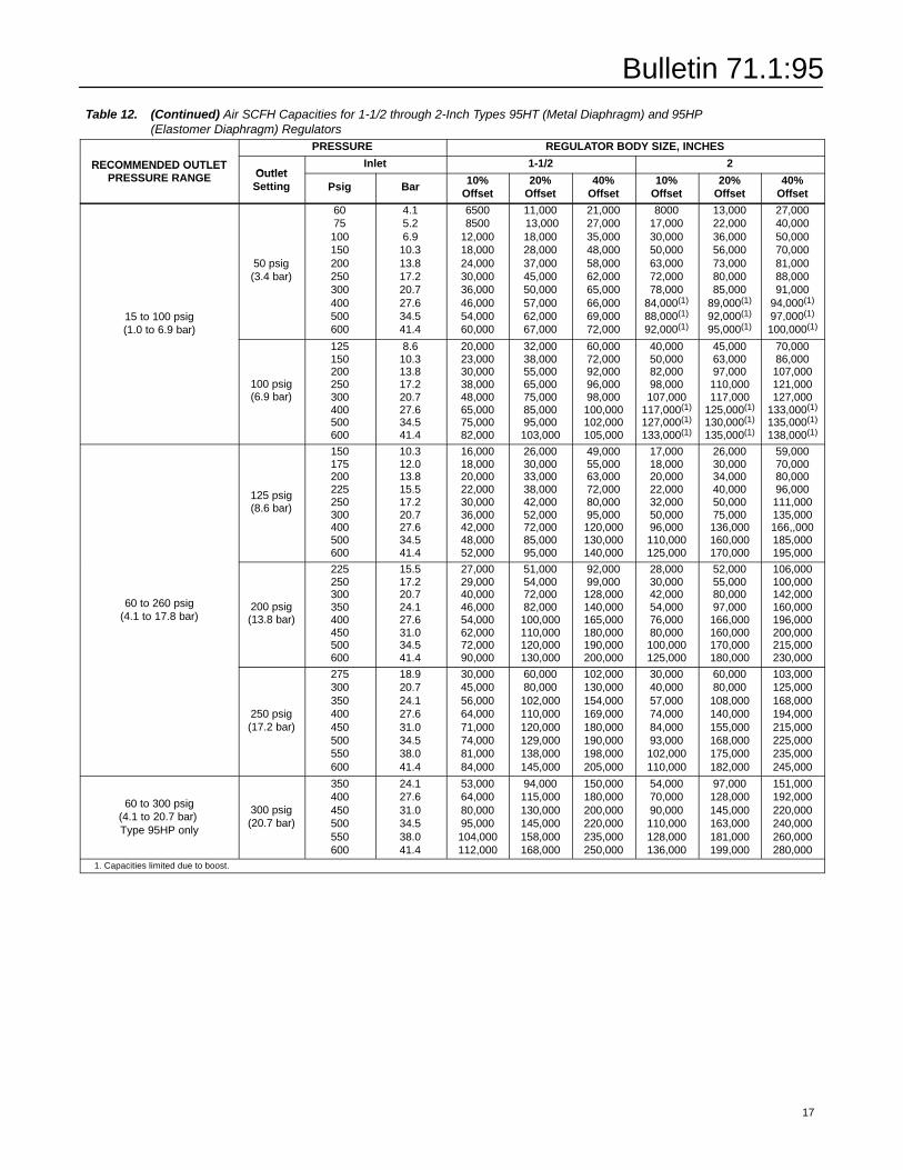
Table 12. (Continued) Air SCFH Capacities for 1-1/2 through 2-Inch Types 95HT (Metal Diaphragm) and 95HP(Elastomer Diaphragm) RegulatorsPRESSURE REGULATOR BODY SIZE, INCHES
RECOMMENDED OUTLETPRESSURE RANGE Outlet
Inlet 1-1/2 2RECOMMENDED OUTLETPRESSURE RANGE Outlet
Setting Psig Bar 10%Offset
20%Offset
40%Offset
10%Offset
20%Offset
40%Offset
15 to 100 psig(1.0 to 6.9 bar)
50 psig(3.4 bar)
6075100150200250300400500600
4.15.26.9
10.313.817.220.727.634.541.4
65008500
12,00018,00024,00030,00036,00046,00054,00060,000
11,00013,00018,00028,00037,00045,00050,00057,00062,00067,000
21,00027,00035,00048,00058,00062,00065,00066,00069,00072,000
800017,00030,00050,00063,00072,00078,000
84,000(1)
88,000(1)
92,000(1)
13,00022,00036,00056,00073,00080,00085,000
89,000(1)
92,000(1)
95,000(1)
27,00040,00050,00070,00081,00088,00091,000
94,000(1)
97,000(1)
100,000(1)(1.0 to 6.9 bar)
100 psig(6.9 bar)
125150200250300400500600
8.610.313.817.220.727.634.541.4
20,00023,00030,00038,00048,00065,00075,00082,000
32,00038,00055,00065,00075,00085,00095,000103,000
60,00072,00092,00096,00098,000100,000102,000105,000
40,00050,00082,00098,000107,000
117,000(1)
127,000(1)
133,000(1)
45,00063,00097,000110,000117,000
125,000(1)
130,000(1)
135,000(1)
70,00086,000107,000121,000127,000
133,000(1)
135,000(1)
138,000(1)
125 psig(8.6 bar)
150175200225250300400500600
10.312.013.815.517.220.727.634.541.4
16,00018,00020,00022,00030,00036,00042,00048,00052,000
26,00030,00033,00038,00042,00052,00072,00085,00095,000
49,00055,00063,00072,00080,00095,000120,000130,000140,000
17,00018,00020,00022,00032,00050,00096,000110,000125,000
26,00030,00034,00040,00050,00075,000136,000160,000170,000
59,00070,00080,00096,000111,000135,000166,,000185,000195,000
60 to 260 psig(4.1 to 17.8 bar)
200 psig(13.8 bar)
225250300350400450500600
15.517.220.724.127.631.034.541.4
27,00029,00040,00046,00054,00062,00072,00090,000
51,00054,00072,00082,000100,000110,000120,000130,000
92,00099,000128,000140,000165,000180,000190,000200,000
28,00030,00042,00054,00076,00080,000100,000125,000
52,00055,00080,00097,000166,000160,000170,000180,000
106,000100,000142,000160,000196,000200,000215,000230,000
250 psig(17.2 bar)
275300350400450500550600
18.920.724.127.631.034.538.041.4
30,00045,00056,00064,00071,00074,00081,00084,000
60,00080,000102,000110,000120,000129,000138,000145,000
102,000130,000154,000169,000180,000190,000198,000205,000
30,00040,00057,00074,00084,00093,000102,000110,000
60,00080,000108,000140,000155,000168,000175,000182,000
103,000125,000168,000194,000215,000225,000235,000245,000
60 to 300 psig(4.1 to 20.7 bar)Type 95HP only
300 psig(20.7 bar)
350400450500550600
24.127.631.034.538.041.4
53,00064,00080,00095,000104,000112,000
94,000115,000130,000145,000158,000168,000
150,000180,000200,000220,000235,000250,000
54,00070,00090,000110,000128,000136,000
97,000128,000145,000163,000181,000199,000
151,000192,000220,000240,000260,000280,000
1. Capacities limited due to boost.
17
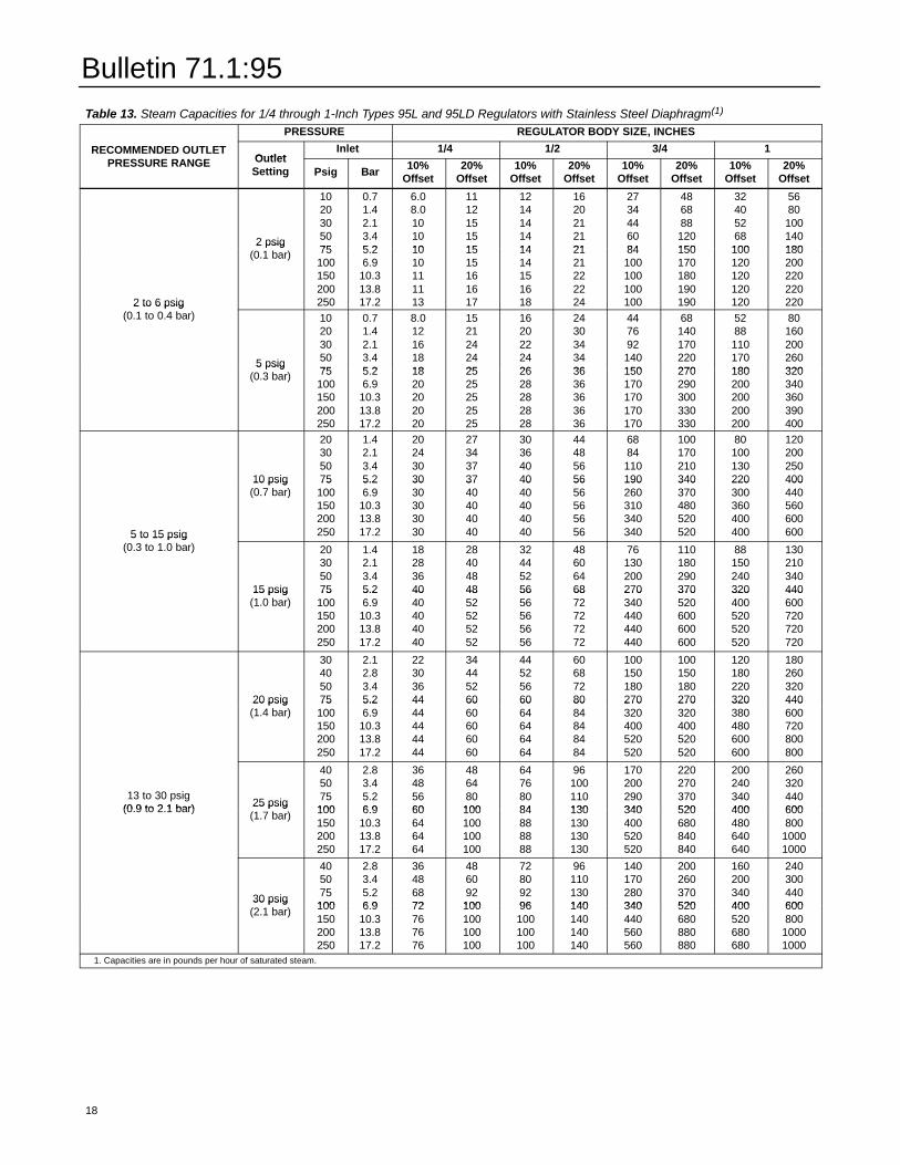
Bulletin 71.1:95
Table 13. Steam Capacities for 1/4 through 1-Inch Types 95L and 95LD Regulators with Stainless Steel Diaphragm(1)PRESSURE REGULATOR BODY SIZE, INCHES
RECOMMENDED OUTLETPRESSURE RANGE Outlet
Inlet 1/4 1/2 3/4 1RECOMMENDED OUTLETPRESSURE RANGE Outlet
Setting Psig Bar 10%Offset
20%Offset
10%Offset
20%Offset
10%Offset
20%Offset
10%Offset
20%Offset
2 psig(0.1 bar)
1020305075
0.71.42.13.45.2
6.08.0101010
1112151515
1214141414
1620212121
2734446084
486888120150
32405268100
5680100140180
2 to 6 psig(0.1 to 0.4 bar)
2 psig(0.1 bar) 75
100150200250
5.26.9
10.313.817.2
1010111113
1515161617
1414151618
2121222224
84100100100100
150170180190190
100120120120120
1802002202202202 to 6 psig
(0.1 to 0.4 bar)
5 psig(0.3 bar)
1020305075
0.71.42.13.45.2
8.012161818
1521242425
1620222426
2430343436
447692140150
68140170220270
5288110170180
80160200260320
5 psig(0.3 bar) 75
100150200250
5.26.9
10.313.817.2
1820202020
2525252525
2628282828
3636363636
150170170170170
270290300330330
180200200200200
320340360390400
10 psig(0.7 bar)
20305075
1.42.13.45.2
20243030
27343737
30364040
44485656
6884110190
100170210340
80100130220
120200250400
5 to 15 psig(0.3 to 1.0 bar)
10 psig(0.7 bar)
75100150200250
5.26.9
10.313.817.2
3030303030
3740404040
4040404040
5656565656
190260310340340
340370480520520
220300360400400
4004405606006005 to 15 psig
(0.3 to 1.0 bar)
15 psig(1.0 bar)
20305075
1.42.13.45.2
18283640
28404848
32445256
48606468
76130200270
110180290370
88150240320
13021034044015 psig
(1.0 bar)75100150200250
5.26.9
10.313.817.2
4040404040
4852525252
5656565656
6872727272
270340440440440
370520600600600
320400520520520
440600720720720
20 psig(1.4 bar)
30405075
2.12.83.45.2
22303644
34445260
44525660
60687280
100150180270
100150180270
120180220320
18026032044020 psig
(1.4 bar)75100150200250
5.26.9
10.313.817.2
4444444444
6060606060
6064646464
8084848484
270320400520520
270320400520520
320380480600600
440600720800800
13 to 30 psig(0.9 to 2.1 bar) 25 psig
(1.7 bar)
405075100
2.83.45.26.9
36485660
486480100
64768084
96100110130
170200290340
220270370520
200240340400
260320440600(0.9 to 2.1 bar) 25 psig
(1.7 bar) 100150200250
6.910.313.817.2
60646464
100100100100
84888888
130130130130
340400520520
520680840840
400480640640
600800
10001000
30 psig(2.1 bar)
405075100
2.83.45.26.9
36486872
486092100
72809296
96110130140
140170280340
200260370520
160200340400
240300440600
30 psig(2.1 bar) 100
150200250
6.910.313.817.2
72767676
100100100100
96100100100
140140140140
340440560560
520680880880
400520680680
600800
10001000
1. Capacities are in pounds per hour of saturated steam.
18
Bulletin 71.1:95
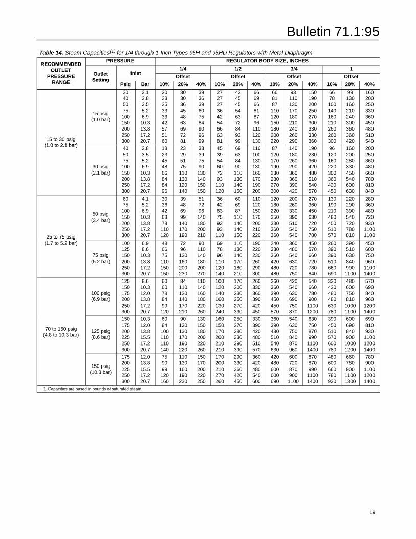
Table 14. Steam Capacities(1) for 1/4 through 1-Inch Types 95H and 95HD Regulators with Metal DiaphragmRECOMMENDEDPRESSURE REGULATOR BODY SIZE, INCHES
RECOMMENDEDOUTLET
Outlet Inlet1/4 1/2 3/4 1OUTLET
PRESSURERANGE
OutletSetting
InletOffset Offset Offset OffsetPRESSURE
RANGE SettingPsig Bar 10% 20% 40% 10% 20% 40% 10% 20% 40% 10% 20% 40%
15 to 30 psig(1.0 to 2.1 bar)
15 psig(1.0 bar)
30405075100150200250300
2.12.83.55.26.9
10.313.817.220.7
202325333342575160
303036454863697281
393639607584909699
272727364254666381
424545546372849399
666966818796110120130
668187110120150180200220
93110130170180210240260290
150190200250270300330330360
6678100140160210260260300
99130160210240300360360420
160200250330360450480510540
(1.0 to 2.1 bar)
30 psig(2.1 bar)
405075100150200250300
2.83.55.26.9
10.313.817.220.7
1823454866848496
23295175110130120140
33397590130140150150
453954607293110120
69638490110130140150
110100130130160170190200
87120170190230280270300
140180260290360360390420
190230360420480510540570
96120160220300360420450
160200280330450540600630
200250360480660780810840
25 to 75 psig
50 psig(3.4 bar)
6075100150200250300
4.15.26.9
10.313.817.220.7
3036426378110120
39486999140170190
517296140180200210
364263759393110
606987110140140150
110120150170200210220
120180220250330360360
200260330390510540540
270360450630720750780
130190210480450510570
220290390540720780810
280360480720930
1100110025 to 75 psig
(1.7 to 5.2 bar)
75 psig(5.2 bar)
100125150200250300
6.98.6
10.313.817.220.7
486675110150150
7296120160200230
90110140180200270
697896110120140
110130140170180210
190220230260290300
240330360420480480
360480540630720750
450570660720780840
260390390510660690
390510630840990
1100
450600750960
11001400
100 psig(6.9 bar)
125150175200250300
8.610.312.013.817.220.7
6060788499120
84110120140170210
110140160180220260
100120140160130240
170200230250270330
260330360390420450
260360390450450570
420540630690750870
540660780900
11001200
330420480480630780
480600750810
10001100
570690840960
12001400
70 to 150 psig(4.8 to 10.3 bar)
125 psig(8.6 bar)
150175200225250300
10.312.013.815.517.220.7
6084100110110140
90130130170190220
130150180200220260
160150170200210210
250270280330390390
330390420480510570
360390480510540630
540630750840870960
630750870990
11001400
390450510570600780
600690840900
10001200
690810930
110012001400
150 psig(10.3 bar)
175200225250300
12.013.815.517.220.7
759099120160
110130160190230
150170200220250
170200210270260
290330360420450
360420480540600
420480600600690
600720870900
1100
870870990
11001400
480600660780930
660780900
11001300
780900
110012001400
1. Capacities are based in pounds of saturated steam.
19
Bulletin 71.1:95
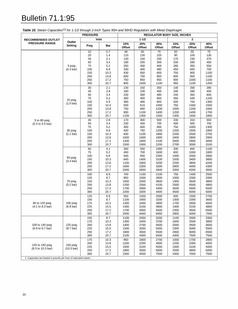
Table 15. Steam Capacities(1) for 1-1/2 through 2-Inch Types 95H and 95HD Regulators with Metal DiaphragmPRESSURE REGULATOR BODY SIZE, INCHES
RECOMMENDED OUTLETPRESSURE RANGE Outlet
Inlet 1-1/2 2RECOMMENDED OUTLETPRESSURE RANGE Outlet
Setting Psig Bar 10%Offset
20%Offset
40%Offset
10%Offset
20%Offset
40%Offset
5 psig(0.3 bar)
1020305075100150200250300
0.71.42.13.45.26.9
10.313.817.220.7
48110130180250330430600750900
50130150200300400550700850
1000
75220250300400480600850950
1100
5090170200280450750800900950
55100230280350600900950
10001100
75130370450550700
1100110011001200
15 psig(1.0 bar)
30405075100150200250300
2.12.83.45.26.9
10.313.817.220.7
130180230300380500750900
1100
150230300400480610950
11001300
250400480650800
1000120014001500
140190240350500750
100012001300
200280350540750
1000120014001500
280400600
110013001500160017001800
5 to 80 psig(0.3 to 5.5 bar)
30 psig(2.1 bar)
405075100150200250300
2.83.45.26.9
10.313.817.220.7
170230300400600
100013001500
300450600750
1100160018001900
500700900
12001800190021002200
230400750
12002200240026002700
310500
100015002500280029003000
550750
130018002700290030003100
50 psig(3.4 bar)
6075100150200250300
4.15.26.9
10.313.817.220.7
300450500640
110016002000
550700950
1400180023002600
1000160023003100320033003400
330600
10001500220028003300
600100020003400380040004200
1100180028003800420043004500
75 psig(5.2 bar)
100125150200250300
6.98.7
10.313.817.220.7
700850
1000120017002200
110015002000250029003300
210028003600410043004400
75010001300250035004500
140023003500450055006000
250033003800480055006000
60 to 120 psig(4.1 to 8.3 bar)
100 psig(6.9 bar)
125150175225250300
6.98.7
10.315.517.220.7
55011001300140017002000
150019002400310035004400
250032003800480055006000
60013001700140023002800
150023002600310035004000
270036004500480065007500
100 to 140 psig(6.9 to 9.7 bar)
125 psig(8.7 bar)
150175200225250300
8.710.313.815.517.220.7
110013001400150018002100
200024002700300035004300
320037004500500055006500
110016002000230028004300
200025003500500060007500
330038004500550065007500
120 to 150 psig(8.3 to 10.3 bar)
150 psig(10.3 bar)
175200225250300
10.313.815.517.220.7
9501200150018002300
16002200310035004500
27004000500060007500
10001200150025004300
17002300310048007000
28004000500060007500
1. Capacities are based in pounds per hour of saturated steam.
20
Bulletin 71.1:95
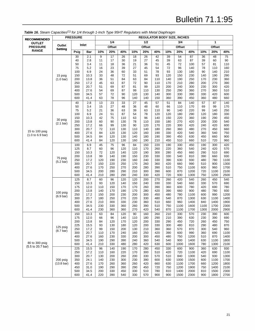
Table 16. Steam Capacities(1) for 1/4 through 1-Inch Type 95HT Regulators with Metal DiaphragmRECOMMENDEDPRESSURE REGULATOR BODY SIZE, INCHES
RECOMMENDEDOUTLET
Outlet Inlet1/4 1/2 3/4 1OUTLET
PRESSURERANGE
OutletSetting
InletOffset Offset Offset OffsetPRESSURE
RANGE SettingPsig Bar 10% 20% 40% 10% 20% 40% 10% 20% 40% 10% 20% 40%
15 psig(1.0 bar)
30405075100150200250300400500600
2.12.83.45.26.9
10.313.817.220.727.634.541.4
91111162433364551545763
171718233648516369697278
263036396072848787879096
18192127335163728199120140
262736455169849099110130140
424551547893110110120130140150
3939457293120140170200250300360
54637296130150190210240290330390
8787100140180230250280300360390450
3639577890140170200230270330360
486081110140190230270300360420480
7590110160210290360390420510600660
15 to 100 psig(1.0 to 6.9 bar)
30 psig(2.1 bar)
405075100150200250300400500600
2.83.45.26.9
10.313.817.220.727.634.541.4
1315212442606672848484
23273651759099110120120120
33486387110130130130130130130
27363954637890110120140160
4548637896110120140160180190
5760110120140150170180190190210
516690120150180220260330390450
84110140180220270300360420450510
140170220290360420420480540630660
576999120190200240270360450510
8799140180290330420450540660720
140170250330450540600660750900960
75 psig(5.2 bar)
100125150200250300400500600
6.98.7
10.313.817.220.727.634.541.4
45607299120150170200210
7596120140190220250280280
96120140190230250270290290
84110120150160170200210240
150170190230240260280300330
220260300330330360390390420
190220280330390420510600720
330360450540630660750870930
450540660810930990
110012001300
190240290390480510600720750
300420510660780900960
11001200
420570690930
11001300170021002500
100 psig(6.9 bar)
125150175200250300400500600
8.710.312.013.817.220.727.634.541.4
6093110140150180210230230
96120150170200250300330360
120140170190230270330360360
120150170170200220230260270
200240260280300330360390420
270330390420450480510510540
260330360390480540660750870
420540600660780870960
11001100
540660780900
11001300140016001700
260330420480600630840
11001300
450570690780990
1100140017002000
540690780930
12001400190023002900
80 to 300 psig(5.5 to 20.7 bar)
125 psig(8.7 bar)
150175200225250300400500600
10.312.013.815.517.220.727.634.541.4
6366849399110160190210
8496120130150170230290330
120140170180200240330390480
90110120120130160200240280
160180200200210250300360420
260290330330360420450540630
210210290300360390480540600
330390450480570600750900
1000
570630720810870990
120014001600
230230260290300360510630780
390390450480540690870
11001300
600690750870960
1100140018002100
(5.5 to 20.7 bar)
200 psig(13.8 bar)
225250300350400450500600
15.517.220.724.127.631.034.541.4
96110130140170190200220
140160200230260290330390
190220260300360390450540
170170200230260290330330
280300330390420450510570
450510570600660720780900
330420510630630750810900
600720840
10001100120014001500
9001100130015001700190020002300
360420540600660750810900
630690930
11001200140015001800
9301100130017001800210023002700
21
Bulletin 71.1:95
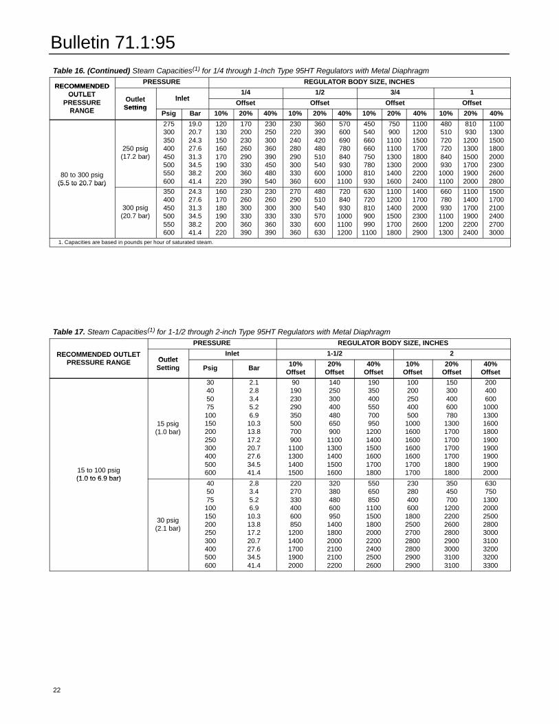
Table 16. (Continued) Steam Capacities(1) for 1/4 through 1-Inch Type 95HT Regulators with Metal DiaphragmRECOMMENDEDPRESSURE REGULATOR BODY SIZE, INCHES
RECOMMENDEDOUTLET
Outlet Inlet1/4 1/2 3/4 1OUTLET
PRESSURERANGE
OutletSetting
InletOffset Offset Offset OffsetPRESSURE
RANGE SettingPsig Bar 10% 20% 40% 10% 20% 40% 10% 20% 40% 10% 20% 40%
80 to 300 psig(5.5 to 20.7 bar)
250 psig(17.2 bar)
275300350400450500550600
19.020.724.327.631.334.538.241.4
120130150160170190200220
170200230260290330360390
230250300360390450480540
230220240280290300330360
360390420480510540600600
570600690780840930
10001100
450540660660750780810930
750900
110011001300130014001600
11001200150017001800200022002400
480510720720840930
10001100
810930
120013001500170019002000
11001300150018002000230026002800(5.5 to 20.7 bar)
300 psig(20.7 bar)
350400450500550600
24.327.631.334.538.241.4
160170180190200220
230260300330360390
230260300330360390
270290300330330360
480510540570600630
720840930
100011001200
630720810900990
1100
110012001400150017001800
140017002000230026002900
660780930
110012001300
110014001700190022002400
150017002100240027003000
1. Capacities are based in pounds per hour of saturated steam.
Table 17. Steam Capacities(1) for 1-1/2 through 2-inch Type 95HT Regulators with Metal DiaphragmPRESSURE REGULATOR BODY SIZE, INCHES
RECOMMENDED OUTLETPRESSURE RANGE Outlet
Inlet 1-1/2 2RECOMMENDED OUTLETPRESSURE RANGE Outlet
Setting Psig Bar 10%Offset
20%Offset
40%Offset
10%Offset
20%Offset
40%Offset
15 to 100 psig(1.0 to 6.9 bar)
15 psig(1.0 bar)
30405075100150200250300400500600
2.12.83.45.26.9
10.313.817.220.727.634.541.4
90190230290350500700900
1100130014001500
140250300400480650900
11001300140015001600
190350400550700950
120014001500160017001800
100200250400500
1000160016001600160017001700
150300400600780
1300170017001700170018001800
200400600
100013001600180019001900190019002000
(1.0 to 6.9 bar)
30 psig(2.1 bar)
405075100150200250300400500600
2.83.45.26.9
10.313.817.220.727.634.541.4
220270330400600850
12001400170019002000
320380480600950
140018002000210021002200
550650850
11001500180020002200240025002600
230280400600
1800250027002800280029002900
350450700
12002200260028002900300031003100
630750
130020002500280030003100320032003300
22
Bulletin 71.1:95
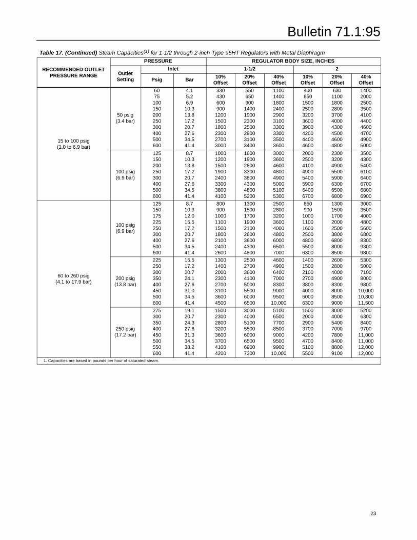
Table 17. (Continued) Steam Capacities(1) for 1-1/2 through 2-inch Type 95HT Regulators with Metal DiaphragmPRESSURE REGULATOR BODY SIZE, INCHES
RECOMMENDED OUTLETPRESSURE RANGE Outlet
Inlet 1-1/2 2RECOMMENDED OUTLETPRESSURE RANGE Outlet
Setting Psig Bar 10%Offset
20%Offset
40%Offset
10%Offset
20%Offset
40%Offset
15 to 100 psig(1.0 to 6.9 bar)
50 psig(3.4 bar)
6075100150200250300400500600
4.15.26.9
10.313.817.220.727.634.541.4
330430600900
120015001800230027003000
550650900
1400190023002500290031003400
1100140018002400290031003300330035003600
400850
15002500320036003900420044004600
630110018002800370040004300450046004800
1400200025003500410044004600470049005000(1.0 to 6.9 bar)
100 psig(6.9 bar)
125150200250300400500600
8.710.313.817.220.727.634.541.4
10001200150019002400330038004100
16001900280033003800430048005200
30003600460048004900500051005300
20002500410049005400590064006700
23003200490055005900630065006800
35004300540061006400670068006900
100 psig(6.9 bar)
125150175225250300400500600
8.710.312.015.517.220.727.634.541.4
800900
1000110015001800210024002600
130015001700190021002600360043004800
250028003200360040004800600065007000
850900
1000110016002500480055006300
130015001700200025003800680080008500
300035004000480056006800830093009800
60 to 260 psig(4.1 to 17.9 bar)
200 psig(13.8 bar)
225250300350400450500600
15.517.220.724.127.631.034.541.4
13001400200023002700310036004500
25002700360041005000550060006500
4600490064007000830090009500
10,000
14001500210027003800400050006300
26002800400049008300800085009000
53005000710080009800
10,00010,80011,500
250 psig(17.2 bar)
275300350400450500550600
19.120.724.327.631.334.538.241.4
15002300280032003600370041004200
30004000510055006000650069007300
5100650077008500900095009900
10,000
15002000290037004200470051005500
30004000540070007800840088009100
5200630084009700
11,00011,00012,00012,000
1. Capacities are based in pounds per hour of saturated steam.
23
Bulletin 71.1:95
Table 18. Water Capacities in GPM for 1/4 through 1-Inch Types 95L and 95LD Regulators with Elastomer Diaphragm(1, 2)PRESSURE REGULATOR BODY SIZE, INCHES
RECOMMENDED OUTLETPRESSURE RANGE Outlet
Inlet 1/4 1/2 3/4 1RECOMMENDED OUTLETPRESSURE RANGE Outlet
Setting Psig Bar 10%Offset
20%Offset
10%Offset
20%Offset
10%Offset
20%Offset
10%Offset
20%Offset
2 to 6 psig(0.1 to 0.4 bar)
5 psig(0.3 bar)
1020305075
0.71.42.13.45.2
1.02.02.32.72.7
1.83.03.33.53.5
2.02.83.33.73.7
3.34.04.74.84.8
5.07.5101111
7.011131720
5.89.2121313
8.313162023
2 to 6 psig(0.1 to 0.4 bar)
5 psig(0.3 bar) 75
100150200250
5.26.9
10.313.817.2
2.72.72.72.72.7
3.53.53.53.53.5
3.73.73.73.73.7
4.84.84.84.84.8
1111111111
2022222222
1313131313
2327272727
10 psig(0.7 bar)
20305075
1.42.13.45.2
1.82.53.03.0
2.73.53.83.8
3.74.04.24.2
5.05.25.35.3
7.0101212
10131720
8.3121414
12162025
5 to 15 psig(0.3 to 1.0 bar)
10 psig(0.7 bar)
75100150200250
5.26.9
10.313.817.2
3.03.03.03.03.0
3.83.83.83.83.8
4.24.24.24.24.2
5.35.35.35.35.3
1212121212
2022222222
1414141414
25272727275 to 15 psig
(0.3 to 1.0 bar)
15 psig(1.0 bar)
20305075
1.42.13.45.2
1.82.73.53.7
2.23.34.34.5
3.54.74.85.0
5.05.86.26.3
7.0111515
8.5131722
8.3131818
1015202715 psig
(1.0 bar)75100150200250
5.26.9
10.313.817.2
3.73.73.73.73.7
4.54.54.54.54.5
5.05.05.05.05.0
6.36.36.36.36.3
1515151517
2228323535
1818181820
2733374242
20 psig(1.4 bar)
30405075
2.12.83.45.2
2.02.73.33.8
2.93.84.75.0
4.35.25.55.5
5.86.77.27.2
10131418
11131720
12151722
1316202520 psig
(1.4 bar)75100150200250
5.26.9
10.313.817.2
3.83.83.83.83.8
5.05.05.05.05.0
5.55.55.55.55.5
7.27.27.27.27.2
1822232325
2027323738
2225272730
2532384345
13 to 30 psig(0.9 to 2.1 bar) 25 psig
(1.7 bar)
405075100
2.83.45.26.9
2.63.33.74.2
3.54.35.85.8
5.25.85.85.8
7.57.88.08.0
13142223
13162227
15172528
16192732(0.9 to 2.1 bar) 25 psig
(1.7 bar) 100150200250
6.910.313.817.2
4.24.24.24.2
5.85.85.85.8
5.85.85.85.8
8.08.08.08.0
23283335
27323841
28334042
32384548
30 psig(2.1 bar)
405075100
2.83.45.26.9
2.33.24.34.8
3.04.05.76.3
5.36.56.76.7
7.38.39.29.2
10132024
12152227
12162328
14182532
30 psig(2.1 bar) 100
150200250
6.910.313.817.2
4.84.84.84.8
6.33.66.36.3
6.76.76.76.7
9.29.29.29.2
24323740
27334043
28374347
32404750
1. Capacities are in gallons per minute of water.2. To obtain capacities for regulators with metal diaphragms, multiply the table values by 0.8.
24
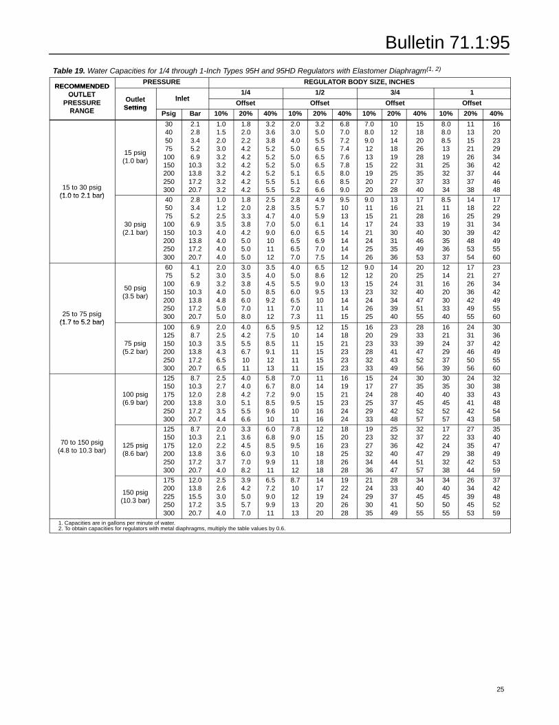
Bulletin 71.1:95
Table 19. Water Capacities for 1/4 through 1-Inch Types 95H and 95HD Regulators with Elastomer Diaphragm(1, 2)RECOMMENDEDPRESSURE REGULATOR BODY SIZE, INCHES
RECOMMENDEDOUTLET
Outlet Inlet1/4 1/2 3/4 1OUTLET
PRESSURERANGE
OutletSetting
InletOffset Offset Offset OffsetPRESSURE
RANGE SettingPsig Bar 10% 20% 40% 10% 20% 40% 10% 20% 40% 10% 20% 40%
15 to 30 psig(1.0 to 2.1 bar)
15 psig(1.0 bar)
30405075100150200250300
2.12.83.45.26.9
10.313.817.220.7
1.01.52.03.03.23.23.23.23.2
1.82.02.24.24.24.24.24.24.2
3.23.63.85.25.25.25.25.55.5
2.03.04.05.05.05.05.15.15.2
3.25.05.56.56.56.56.56.66.6
6.87.07.27.47.67.88.08.59.0
7.08.09.0121315192020
101214181922252728
151820262831353740
8.08.08.5131925323334
111315212636373738
162023293442444648
(1.0 to 2.1 bar)
30 psig(2.1 bar)
405075100150200250300
2.83.45.26.9
10.313.817.220.7
1.01.22.53.54.04.04.04.0
1.82.03.33.84.25.05.05.0
2.52.84.77.09.0101112
2.83.54.05.06.06.56.57.0
4.95.75.96.16.56.97.07.5
9.510131414141414
9.011151721242526
1316212430313536
1721283340464953
8.511161930353637
1418253139485354
1722293442495560
25 to 75 psig(1.7 to 5.2 bar)
50 psig(3.5 bar)
6075100150200250300
4.15.26.9
10.313.817.220.7
2.03.03.24.04.85.05.0
3.03.53.85.06.07.08.0
3.54.04.58.59.21112
4.05.05.56.06.57.07.3
6.58.69.09.5101111
12121313141415
9.0121523242625
14202432343940
20253140475155
12141620303340
17212636424955
23273442495560
(1.7 to 5.2 bar)
75 psig(5.2 bar)
100125150200250300
6.98.7
10.313.817.220.7
2.02.53.54.36.56.5
4.04.25.56.71011
6.57.58.59.11213
9.51011111111
121415151515
151821232323
162023283233
232933414349
283339475256
162124293739
243137465056
303642495560
100 psig(6.9 bar)
125150175200250300
8.710.312.013.817.220.7
2.52.72.83.03.54.4
4.04.04.25.15.56.6
5.86.77.28.59.610
7.08.09.09.51011
111415151616
161921232424
151724252933
242728374248
303540455257
303540455257
243033414243
323843485458
70 to 150 psig(4.8 to 10.3 bar)
125 psig(8.6 bar)
125150175200250300
8.710.312.013.817.220.7
2.02.12.23.63.74.0
3.33.64.56.07.08.2
6.06.88.59.39.911
7.89.09.5101112
121516181818
182023252628
192327323436
253236404447
323742475157
172224293238
273335384244
354047495359
150 psig(10.3 bar)
175200225250300
12.013.815.517.220.7
2.52.63.03.54.0
3.94.25.05.77.0
6.57.29.09.911
8.710121313
1417192020
1922242628
2124293035
2833374149
3440455055
3440455055
2634394553
3742485259
1. Capacities are in gallons per minute of water.2. To obtain capacities for regulators with metal diaphragms, multiply the table values by 0.6.
25
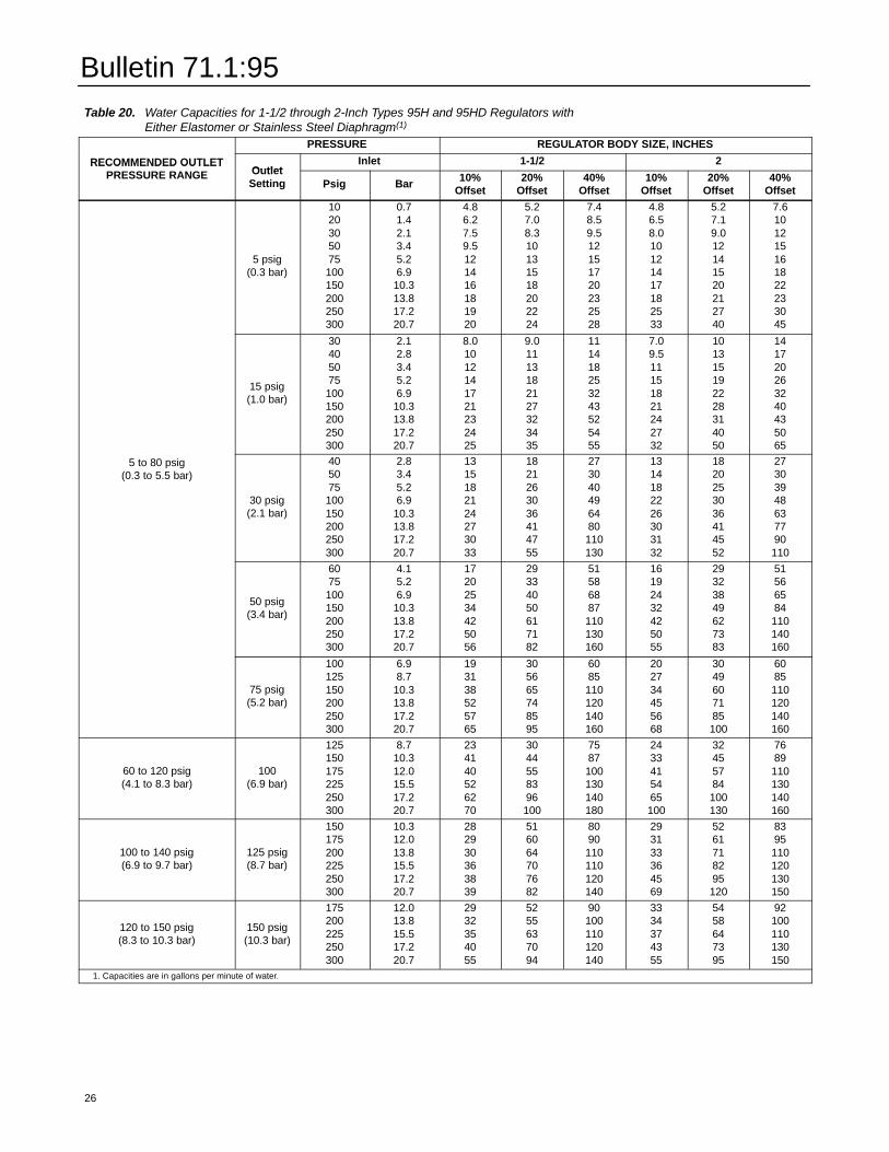
Bulletin 71.1:95
Table 20. Water Capacities for 1-1/2 through 2-Inch Types 95H and 95HD Regulators withEither Elastomer or Stainless Steel Diaphragm(1)
PRESSURE REGULATOR BODY SIZE, INCHES
RECOMMENDED OUTLETPRESSURE RANGE Outlet
Inlet 1-1/2 2RECOMMENDED OUTLETPRESSURE RANGE Outlet
Setting Psig Bar 10%Offset
20%Offset
40%Offset
10%Offset
20%Offset
40%Offset
5 psig(0.3 bar)
1020305075100150200250300
0.71.42.13.45.26.9
10.313.817.220.7
4.86.27.59.5121416181920
5.27.08.310131518202224
7.48.59.512151720232528
4.86.58.010121417182533
5.27.19.012141520212740
7.6101215161822233045
15 psig(1.0 bar)
30405075100150200250300
2.12.83.45.26.9
10.313.817.220.7
8.01012141721232425
9.01113182127323435
111418253243525455
7.09.511151821242732
101315192228314050
141720263240435065
5 to 80 psig(0.3 to 5.5 bar)
30 psig(2.1 bar)
405075100150200250300
2.83.45.26.9
10.313.817.220.7
1315182124273033
1821263036414755
273040496480110130
1314182226303132
1820253036414552
27303948637790110
50 psig(3.4 bar)
6075100150200250300
4.15.26.9
10.313.817.220.7
17202534425056
29334050617182
51586887110130160
16192432425055
29323849627383
51566584110140160
75 psig(5.2 bar)
100125150200250300
6.98.7
10.313.817.220.7
193138525765
305665748595
6085110120140160
202734455668
3049607185100
6085110120140160
60 to 120 psig(4.1 to 8.3 bar)
100(6.9 bar)
125150175225250300
8.710.312.015.517.220.7
234140526270
3044558396100
7587100130140180
2433415465100
32455784100130
7689110130140160
100 to 140 psig(6.9 to 9.7 bar)
125 psig(8.7 bar)
150175200225250300
10.312.013.815.517.220.7
282930363839
516064707682
8090110110120140
293133364569
5261718295120
8395110120130150
120 to 150 psig(8.3 to 10.3 bar)
150 psig(10.3 bar)
175200225250300
12.013.815.517.220.7
2932354055
5255637094
90100110120140
3334374355
5458647395
92100110130150
1. Capacities are in gallons per minute of water.
26
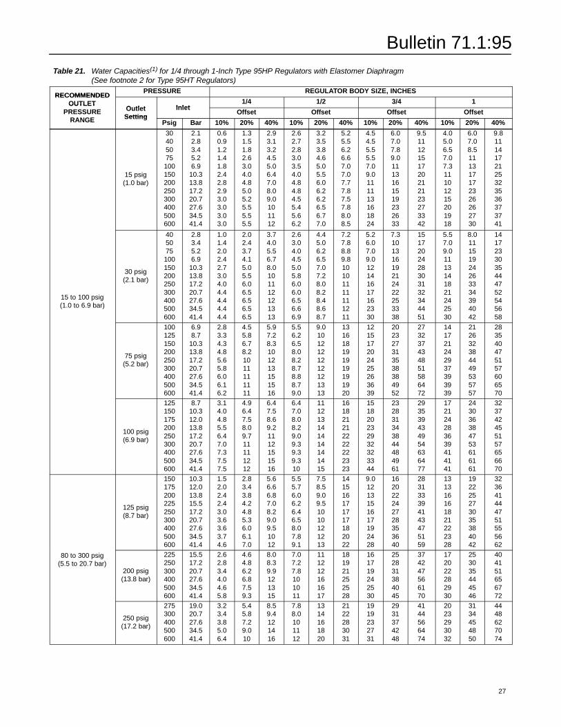
Bulletin 71.1:95
Table 21. Water Capacities(1) for 1/4 through 1-Inch Type 95HP Regulators with Elastomer Diaphragm(See footnote 2 for Type 95HT Regulators)
RECOMMENDEDPRESSURE REGULATOR BODY SIZE, INCHES
RECOMMENDEDOUTLET
Outlet Inlet1/4 1/2 3/4 1OUTLET
PRESSURERANGE
OutletSetting
InletOffset Offset Offset OffsetPRESSURE
RANGE SettingPsig Bar 10% 20% 40% 10% 20% 40% 10% 20% 40% 10% 20% 40%
15 psig(1.0 bar)
30405075100150200250300400500600
2.12.83.45.26.9
10.313.817.220.727.634.541.4
0.60.91.21.41.82.42.82.93.03.03.03.0
1.31.51.82.63.04.04.85.05.25.55.55.5
2.93.13.24.55.06.47.08.09.0101112
2.62.72.83.03.54.04.84.84.55.45.66.2
3.23.53.84.65.05.56.06.26.26.56.77.0
5.25.56.26.67.07.07.77.87.57.88.08.5
4.54.55.55.57.09.0111113161824
6.07.07.89.01113161519232633
9.51112151720212123273342
4.05.06.57.07.311101215201918
6.07.08.5111317172326262730
9.81114172125323536373741
15 to 100 psig(1.0 to 6.9 bar)
30 psig(2.1 bar)
405075100150200250300400500600
2.83.45.26.9
10.313.817.220.727.634.541.4
1.01.42.02.42.73.04.04.44.44.44.4
2.02.43.74.15.05.56.06.56.56.56.5
3.74.05.56.78.0101112121313
2.63.04.04.55.05.86.06.06.56.66.9
4.45.06.26.57.07.28.08.28.48.68.7
7.27.88.89.810101111111211
5.26.07.09.012141617162330
7.310131619212422253338
1517202428303132344451
5.57.09.01113141821242530
8.011151924263334394042
1417233035444752545658
75 psig(5.2 bar)
100125150200250300400500600
6.98.7
10.313.817.220.727.634.541.4
2.83.34.34.85.65.86.06.16.2
4.55.86.78.21011111111
5.97.28.3101213151516
5.56.26.58.08.28.78.88.79.0
9.01012121212121313
131618191919191920
121517202425263639
202327313538384952
273237434851586472
141721242937393939
212632384449535757
283540475157606570
100 psig(6.9 bar)
125150175200250300400500600
8.710.312.013.817.220.727.634.541.4
3.14.04.85.56.47.07.37.57.5
4.96.47.58.09.711111212
6.47.58.69.21112151516
6.47.08.08.29.09.39.39.310
111213141414141415
161821212222222323
151820232932323344
232831343844484961
293539434954636477
172124283639414141
243036384753616161
323742455157656670
125 psig(8.7 bar)
150175200225250300400500600
10.312.013.815.517.220.727.634.541.4
1.52.02.42.43.03.63.63.74.6
2.83.43.84.24.85.36.06.17.0
5.66.66.87.08.29.09.51012
5.55.76.06.26.46.58.07.89.1
7.58.59.09.51010121213
141516171717182022
9.01213151617192428
162022242728353640
283133394143475159
131316161821222328
192225273035384042
323641444751555662
80 to 300 psig(5.5 to 20.7 bar)
200 psig(13.8 bar)
225250300400500600
15.517.220.727.634.541.4
2.62.83.44.04.65.8
4.64.86.26.87.59.3
8.08.39.9121315
7.07.27.8101011
111212161617
181921252528
161719242530
252831384045
374247566170
172022282930
253035444546
404151656772
250 psig(17.2 bar)
275300400500600
19.020.727.634.541.4
3.23.43.85.06.4
5.45.87.29.010
8.59.4121416
7.88.0101112
1314161820
2122283031
1919232731
2931374248
4144566474
2023293032
3134454850
4448627074
27
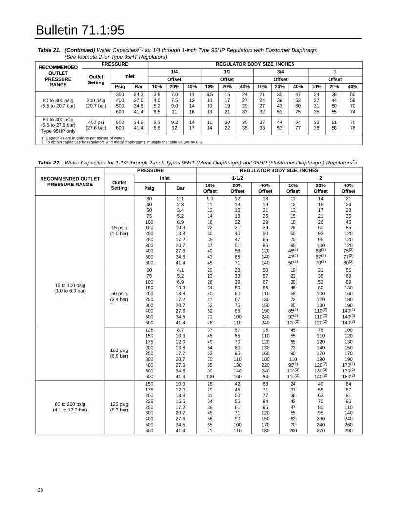
Bulletin 71.1:95
Table 21. (Continued) Water Capacities(1) for 1/4 through 1-Inch Type 95HP Regulators with Elastomer Diaphragm(See footnote 2 for Type 95HT Regulators)
RECOMMENDEDPRESSURE REGULATOR BODY SIZE, INCHES
RECOMMENDEDOUTLET
Outlet Inlet1/4 1/2 3/4 1OUTLET
PRESSURERANGE
OutletSetting
InletOffset Offset Offset OffsetPRESSURE
RANGE SettingPsig Bar 10% 20% 40% 10% 20% 40% 10% 20% 40% 10% 20% 40%
80 to 300 psig(5.5 to 20.7 bar)
300 psig(20.7 bar)
350400500600
24.327.634.541.4
3.84.05.26.5
7.07.59.011
11121416
9.5101013
15171921
24272933
21242732
35394351
47536075
24273135
38445055
50587074
80 to 400 psig(5.5 to 27.6 bar)Type 95HP only
400 psi(27.6 bar)
500600
34.541.4
5.36.6
9.212
1417
1114
2022
3035
2733
4453
6477
3238
5158
7076
1. Capacities are in gallons per minute of water.2. To obtain capacities for regulators with metal diaphragms, multiply the table values by 0.6.
Table 22. Water Capacities for 1-1/2 through 2-Inch Types 95HT (Metal Diaphragm) and 95HP (Elastomer Diaphragm) Regulators(1)
PRESSURE REGULATOR BODY SIZE, INCHES
RECOMMENDED OUTLETPRESSURE RANGE Outlet
Inlet 1-1/2 2RECOMMENDED OUTLETPRESSURE RANGE Outlet
Setting Psig Bar 10%Offset
20%Offset
40%Offset
10%Offset
20%Offset
40%Offset
15 psig(1.0 bar)
30405075100150200250300400500600
2.12.83.45.26.9
10.313.817.220.727.634.541.4
9.01112141622303537404345
121315182231404751586571
181921252939506585120140140
111213151829507085
45(2)
47(2)
50(2)
141617212650929510063(2)
67(2)
70(2)
21242835458512012012075(2)
77(2)
80(2)
15 to 100 psig(1.0 to 6.9 bar) 50 psig
(3.4 bar)
6075100150200250300400500600
4.15.26.9
10.313.817.220.727.634.541.4
20232634404752627176
2833395060677585100110
50576786110130150190240240
19233045587285
85(2)
92(2)
100(2)
31385280100120130
110(2)
110(2)
120(2)
566989130160180190
140(2)
140(2)
140(2)
100 psig(6.9 bar)
125150175200250300400500600
8.710.312.013.817.220.727.634.541.4
3745495463708590100
5765708095110130140160
95110120130160180220240260
455565739011093(2)
100(2)
110(2)
75110120140170190
120(2)
130(2)
140(2)
100120130150170190
170(2)
170(2)
180(2)
60 to 260 psig(4.1 to 17.2 bar)
125 psig(8.7 bar)
150175200225250300400500600
10.312.013.815.517.220.727.634.541.4
282931343845586571
42455055617190100110
6871778495120150170180
2431364247556270200
495563708095230240270
84879196110140240260290
28
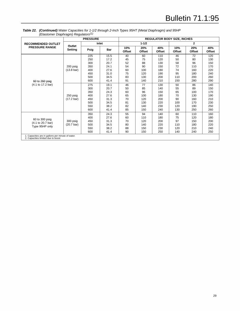
Bulletin 71.1:95
Table 22. (Continued) Water Capacities for 1-1/2 through 2-Inch Types 95HT (Metal Diaphragm) and 95HP(Elastomer Diaphragm) Regulators(1)
PRESSURE REGULATOR BODY SIZE, INCHES
RECOMMENDED OUTLETPRESSURE RANGE Outlet
Inlet 1-1/2 2RECOMMENDED OUTLETPRESSURE RANGE Outlet
Setting Psig Bar 10%Offset
20%Offset
40%Offset
10%Offset
20%Offset
40%Offset
60 to 260 psig(4.1 to 17.2 bar)
200 psig(13.8 bar)
225250300350400450500600
15.517.220.724.127.631.034.541.4
4045525460758391
60758890100120130140
110120130150180190200210
465058727495110150
728096110160180200280
12013015017022024026029060 to 260 psig
(4.1 to 17.2 bar)
250 psig(17.2 bar)
275300350400450500550600
19.120.724.327.631.334.538.241.4
4650606570818285
778596100120130140150
130140150180200220230240
5055657090100120130
8689100130160170190250
140150170190210230250260
60 to 300 psig(4.1 to 20.7 bar)Type 95HP only
300 psig(20.7 bar)
350400450500550600
24.327.631.334.538.241.4
556070808890
94110120140150150
140180200220230250
607597110120140
110120150180210240
160180200220240250
1. Capacities are in gallons per minute of water.2. Capacities limited due to boost
29
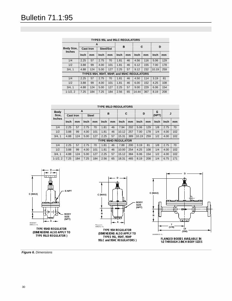
Figure 6. Dimensions
Bulletin 71.1:95
30
TYPES 95L and 95LC REGULATORS
Body Size,A
B C DBody Size,Inches
Cast Iron Steel/SstB C DBody Size,
InchesInch mm Inch mm Inch mm Inch mm Inch mm
1/4 2.25 57 2.75 70 1.81 46 4.56 116 5.06 129
1/2 3.88 99 4.00 101 1.81 46 6.12 155 7.00 178
3/4, 1 4.88 124 5.00 127 2.25 57 9.12 232 10.19 259
TYPES 95H, 95HT, 95HP, and 95HC REGULATORS
1/4 2.25 57 2.75 70 1.81 46 4.50 114 3.19 81
1/2 3.88 99 4.00 101 1.81 46 6.00 152 4.25 108
3/4, 1 4.88 124 5.00 127 2.25 57 9.00 229 6.06 154
1-1/2, 2 7.25 184 7.25 184 2.56 65 14.44 367 8.19 208
TYPE 95LD REGULATORS
Body AB C D
EJ
BodySize,
InchesCast Iron Steel
B C DE
(NPT) JSize,Inches
Inch mm Inch mm Inch mm Inch mm Inch mm Inch Inch mm
1/4 2.25 57 2.75 70 1.81 46 7.94 202 5.06 129 1/8 2.75 70
1/2 3.88 99 4.00 101 1.81 46 10.12 257 7.00 178 1/4 4.00 102
3/4, 1 4.88 124 5.00 127 2.25 57 15.31 389 10.19 259 1/2 4.00 102
TYPE 95HD REGULATOR
1/4 2.25 57 2.75 70 1.81 46 7.88 200 3.19 81 1/8 2.75 70
1/2 3.88 99 4.00 101 1.81 46 10.00 254 4.25 108 1/4 4.00 102
3/4, 1 4.88 124 5.00 127 2.25 57 15.12 384 6.06 154 1/2 4.00 102
1-1/2, 2 7.25 184 7.25 184 2.56 65 18.31 465 8.19 208 1/4 6.75 171
TYPE 95HD REGULATOR(DIMENSIONS ALSO APPLY TO
TYPE 95LD REGULATOR )
AE9236-FA0811-2 / IL
DJ
C (MAX)E-NPT
A
BODYSIZE(NPT)
TYPE 95H REGULATOR(DIMENSIONS ALSO APPLY TO
TYPES 95L, 95HT, 95HP95LC and 95HC REGULATORS )
AJ3324-HA0810-2 / IL
B
D
C (MAX)
A
BODYSIZE(NPT)
FLANGED BODIES AVAILABLE IN1/2 THROUGH 2-INCH BODY SIZES
14A4040-D / IL
B
D
7(178)
14(356)
C (MAX)
Bulletin 71.1:95
Ordering InformationWhen ordering, specify:Application Information
1. Type of gas/liquid being controlled (air, ammonia,water, process chemicals, etc.); list any factors suchas impurities in the gas/liquid that may affect the com-patibility with the regulator trim parts.
2. Specific gravity of the gas/liquid
3. Temperature of the gas/liquid
4. Range of flowing inlet pressure to regulator
5. Outlet pressure setting or range
6. Flow ratesa. Minimum controlled flowb. Normal flowc. Maximum flow
7. Line size and end connection size of adjacent piping
Regulator Information
Refer to the specifications on page 2 and carefully re-view the description to the right of each specificationand in the referenced tables. Specify the desiredselection wherever there is a choice to be made. Al-ways specify the regulator type number.
31
Bulletin 71.1:95
32
For information, contact Fisher Controls:Marshalltown, Iowa 50158 USA28320 Gallardon FranceSao Paulo 05424 BrazilSingapore 128461
The contents of this publication are presented for informational purposes only, and while every effort has been made to ensure their accuracy, they are not to be construed as warranties or guarantees,expressor implied, regarding the products or services described herein or their use or applicability. We reserve the right to modify or improve the designs or specifications of such products at any time without notice.
Printed in U.S.A.
Fisher, Fisher-Rosemount, and Managing The Process Better are marks owned by Fisher Controls International, Inc. or Fisher-Rosemount Systems, Inc.All other marks are the property of their respective owners.
EFisher Controls International, Inc. 1963, 1997; All Rights Reserved