Embed Size (px)
Citation preview
1
1. Installation to the Start of Operation
2. Unit Model
3. Specifications
4. Component Part Names and Functions
5. External Dimensions
6. Installation to the Panel
7. Wiring to Power Source and Sensors (DT-501XA/DT-501XD)
8. Wiring to Power Source and Sensors (DT-501FA)
9. Basic Setting Procedure
10. Keys to be Used for Various Settings and Their Applications
11. Teaching Function Settings
12. About Mode
13. When You Select Mode 1 (Digital Tachometer Mode) for Measurement
14. When You Select Mode 2 (Elapsed Timecounter Mode) for Measurement
15. When You Select Mode 3 (Time Width Meter Mode) for Measurement
16. When You Select Mode 4 (Flowmeter Mode) for Measurement
17. Setting Method of Functions (Excluding in the Test Mode, Common in Each Mode)
18. Comparator Function
19. Memory Function
20. Test Mode (Function to Check if the Unit is Operating Normally)
21. Error Display
22. Parameter List
23. Function List
24. Option -FVT/-FVC
25. Option -BCD
26. Option -TRT
27. Option -CPT
28. DT-501X / DT-501F series model list
CAUTION
Precautions before usePower• Be sure to use the unit under the specified voltage (AC power
specifications: 85 - 264VAC / DC power specifications: 10.8 - 25.2VDC).• Inverter power source cannot be used.
Input signal wire• Connection wiring from sensors shall not be kept in the same or parallel conduit or
cable as the power source, power or high voltage cables. If you fail to separate thewiring, noise may be superimposed on the signal wire, resulting in malfunctions.
• Use shielded wire for input power connections with the shortest possible metal conduit.
Terminal• Check that the screws have not come loose due to vibrations after a certain period of time.
Operating environment• Do not install the unit in the following places or conditions.
・Places exposed to direct sunlight, or places where the ambient temperature exceeds a range of 0 - 45ºC.
・Places where the relative humidity percentage exceeds a range of 35 - 85%, orplaces subject to condensation due to rapid change in humidity.
・Places subject to corrosive and/or combustible gases.・Places subject to a large amount of dust, salinity, and/or ferric substance.・Places susceptible to noise (including static electricity).
98211B
!
!
INDEX
Digital Tachometer
2
2
3
3
4
4
5
6
6
6
7
8
8
10
12
14
16
17
18
19
19
20
21
23
25
27
27
28
A f t e r r e a d i n g, b e s u r e t o s t o r e t h i s m a n u a l i n a s a fe , convenient place where operators can always refer to it easily.
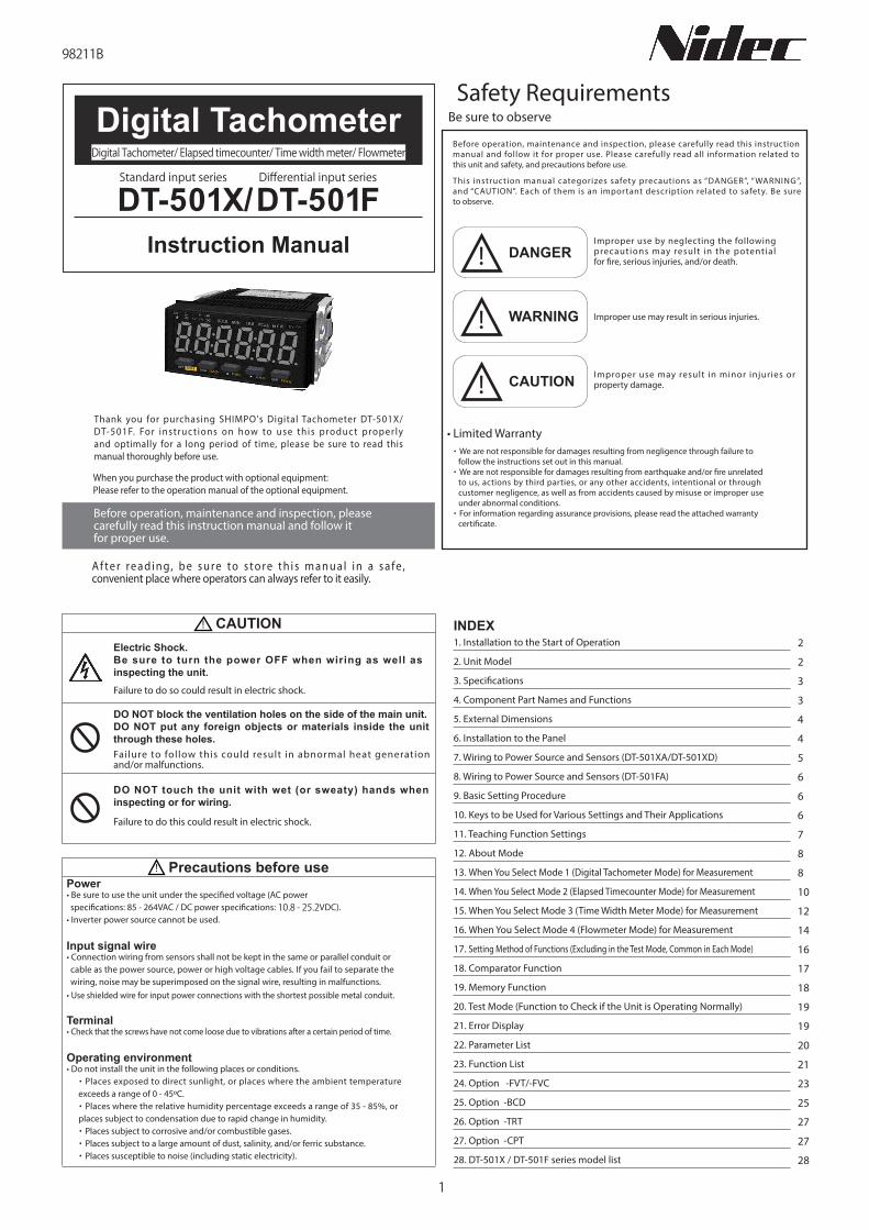
Thank you for purchasing SHIMPO's Digital Tachometer DT-501X/ DT-501F. For instruc t ions on how to use this produc t proper ly and optimally for a long period of time, please be sure to read this manual thoroughly before use.
When you purchase the product with optional equipment:Please refer to the operation manual of the optional equipment.
Before operation, maintenance and inspection, please carefully read this instruction manual and follow it for proper use.
DT-501X/DT-501FStandard input series Differential input series
Instruction Manual
Digital Tachometer/ Elapsed timecounter/ Time width meter/ Flowmeter
Electric Shock.Be sure to turn the power OFF when wiring as well as inspecting the unit.
DO NOT block the ventilation holes on the side of the main unit.DO NOT put any foreign objects or materials inside the unit through these holes.
DO NOT touch the unit with wet (or sweaty) hands when inspecting or for wiring.
Failure to do so could result in electric shock.
Failure to follow this could result in abnormal heat generation and/or malfunctions.
Failure to do this could result in electric shock.
Before operation, maintenance and inspection, please carefully read this instruction manual and follow it for proper use. Please carefully read all information related to this unit and safety, and precautions before use.
・We are not responsible for damages resulting from negligence through failure to follow the instructions set out in this manual.
・We are not responsible for damages resulting from earthquake and/or fire unrelated to us, actions by third parties, or any other accidents, intentional or through customer negligence, as well as from accidents caused by misuse or improper use under abnormal conditions.
・For information regarding assurance provisions, please read the attached warranty certificate.
WARNING Improper use may result in serious injuries.
CAUTION Improper use may result in minor injuries or property damage.
DANGERImproper use by neglecting the following precautions may result in the potential for fire, serious injuries, and/or death.
Safety RequirementsBe sure to observe
!
!
!
• Limited Warranty
This instruction manual categorizes safety precautions as “DANGER”, “ WARNING”, and “CAUTION”. Each of them is an important description related to safety. Be sure to observe.
2
1. Installation to the Start of Operation
2. Unit Model
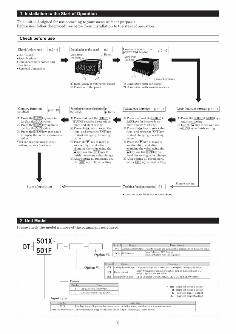
Check before use
Please check the model number of the equipment purchased.
●Unit model●Specifications●Component part names and
functions●External dimensions
Check before use p.2 - 4 Installation to the panel p.4 Connection with thepower and sensor p.5 - 6
DT501X
501F
Option #1
Option #2
Symbol Output FunctionFVT Analog Signal Output Outputs voltage and current that correspond to displayed value
CPT Relay Output Relay Changeover contact output. H output, L output, and GO output, against the set value
TRT Transistor Output Open Collector Output. HH, H, LL, L GO and ZERO output.
Symbol Output Power SourceFVC Analog Signal Output Outputs voltage and current that correspond to displayed value
BCD BCS Output Open Collector, BCD OutputSimple interface with the sequencer
* HH : High set point 2 outputH : High set point 1 outputL : Low set point 1 output
LL : Low set point 2 output
This unit is designed for use according to your measurement purposes.Before use, follow the procedures below from installation to the start of operation.
(1) Installation of waterproof gasket(2) Fixation to the panel
View fromthe front
Panel
(1) Connection with the power(2) Connection with various sensors
View from the back
Connecting wires
Simple setting
●Parameter settings are not necessary.
Start of operation
Mode (function) settings p.8 - 15Memory functionsettings p.17 - 19 Parameter settings p.8 - 15
Teaching function settings P7
(1) Press the MEM key once to display the MAX value.(2) Press the MEM key again to display the MIN value.(3) Press the MEM key once again to display the normal measurement value.*You can use the unit without
setting various functions.
(1) Press the SHIFT + MOD keys and start setting.
(2) Use the ▲ key to set, and use the SET key to finish setting.
(1) Press and hold the SHIFT +PAR keys for 5 seconds or more and start setting.
(2) Press the ▲ key to select the item, and press the ENT key to start changing the setting value.(3) Press the
▲
key to move to another digit, and after changing the value using the ▲ key, use the ENT key to
finish the setting value change.(3) After setting all parameters, use the SET key to finish setting.
(1) Press and hold the SHIFT + FUNC keys for 5 seconds or more and start setting.
(2) Press the ▲ key to select the item, and press the ENT key to start changing the setting value.(3) Press the
▲
key to move to another digit, and after changing the value using the ▲ key, use the ENT key to
finish the setting value change.(4) After setting all functions, use
the SET key to finish setting.
Function (action configuration)settings
p.8p.16 -17
Input typeSymbol Input type501X Standard input : Supports the sensor input, including rotary encoders, and magnetic sensors
501F(AC Power only) Differential input Supports the line driver output, including AC servo motors
PowerSymbol Power
A AC power (85 - 264VAC)D DC power (10.8 - 25.2VDC)
3
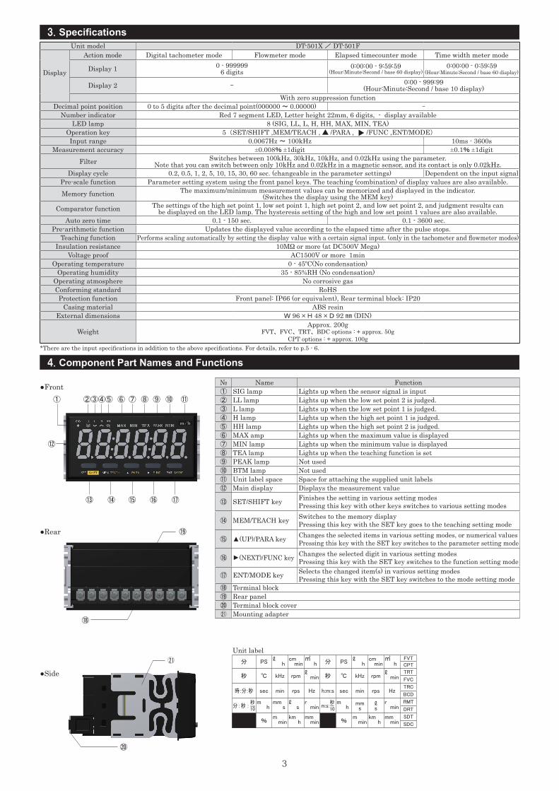
Unit model DT-501X / DT-501F
Display
Action mode Digital tachometer mode Flowmeter mode Elapsed timecounter mode Time width meter mode
Display 1 0 - 9999996 digits
0:00:00 - 9:59:59 (Hour:Minute:Second / base 60 display)
0:00:00 - 0:59:59 (Hour:Minute:Second / base 60 display)
Display 2 - 0:00 - 999:99(Hour:Minute:Second / base 10 display)
With zero suppression functionDecimal point position 0 to 5 digits after the decimal point(000000 ~ 0.00000) -
Number indicator Red 7 segment LED, Letter height 22mm, 6 digits, - display availableLED lamp 8 (SIG, LL, L, H, HH, MAX, MIN, TEA)
Operation key 5 (SET/SHIFT ,MEM/TEACH , ▲ /PARA , ▲ /FUNC ,ENT/MODE)
Input range 0.0067Hz ~ 100kHz 10ms - 3600sMeasurement accuracy ±0.008% ±1digit ±0.1% ±1digit
Filter Switches between 100kHz, 30kHz, 10kHz, and 0.02kHz using the parameter. Note that you can switch between only 10kHz and 0.02kHz in a magnetic sensor, and its contact is only 0.02kHz.
Display cycle 0.2, 0.5, 1, 2, 5, 10, 15, 30, 60 sec. (changeable in the parameter settings) Dependent on the input signalPre-scale function Parameter setting system using the front panel keys. The teaching (combination) of display values are also available.Memory function The maximum/minimum measurement values can be memorized and displayed in the indicator.
(Switches the display using the MEM key)Comparator function The settings of the high set point 1, low set point 1, high set point 2, and low set point 2, and judgment results can
be displayed on the LED lamp. The hysteresis setting of the high and low set point 1 values are also available.Auto zero time 0.1 - 150 sec. 0.1 - 3600 sec.
Pre-arithmetic function Updates the displayed value according to the elapsed time after the pulse stops.Teaching function Performs scaling automatically by setting the display value with a certain signal input. (only in the tachometer and flowmeter modes)
Insulation resistance 10MΩ or more (at DC500V Mega)Voltage proof AC1500V or more 1min
Operating temperature 0 - 45ºC(No condensation)Operating humidity 35 - 85%RH (No condensation)
Operating atmosphere No corrosive gasConforming standard RoHSProtection function Front panel: IP66 (or equivalent), Rear terminal block: IP20
Casing material ABS resinExternal dimensions W 96 × H 48 × D 92 ㎜ (DIN)
WeightApprox. 200g
FVT、 FVC、 TRT、 BDC options : + approx. 50gCPT options : + approx. 100g
3. Specifications
4. Component Part Names and Functions
① ②③④⑤ ⑥ ⑦ ⑧ ⑨ ⑩ ⑪
⑬ ⑭ ⑮ ⑯ ⑰
⑲
⑱
⑳
⑫
Unit label分 PS ℓ
hcm min
㎥ h 分 PS ℓ
hcm min
㎥ h
FVT
CPT
秒 ℃ kHz rpmℓ min 秒 ℃ kHz rpm
ℓ min
TRT
FVC
時:分:秒 sec min rps Hz h:m:s sec min rps HzTRC
BCD
分 : 秒 : ―m h
mm s
ℓ s
r min m:s:-
m h
mm s
ℓ s
r min
RMT
DRT
%m min
km h
mm min %
m min
km h
mm min
SDT
SDC
秒
10
秒
10
21
№ Name Function① SIG lamp Lights up when the sensor signal is input② LL lamp Lights up when the low set point 2 is judged.③ L lamp Lights up when the low set point 1 is judged.④ H lamp Lights up when the high set point 1 is judged.⑤ HH lamp Lights up when the high set point 2 is judged.⑥ MAX amp Lights up when the maximum value is displayed⑦ MIN lamp Lights up when the minimum value is displayed⑧ TEA lamp Lights up when the teaching function is set⑨ PEAK lamp Not used⑩ BTM lamp Not used⑪ Unit label space Space for attaching the supplied unit labels⑫ Main display Displays the measurement value
⑬ SET/SHIFT key Finishes the setting in various setting modesPressing this key with other keys switches to various setting modes
⑭ MEM/TEACH key Switches to the memory displayPressing this key with the SET key goes to the teaching setting mode
⑮ ▲(UP)/PARA key Changes the selected items in various setting modes, or numerical valuesPressing this key with the SET key switches to the parameter setting mode
⑯
▲
(NEXT)/FUNC key Changes the selected digit in various setting modesPressing this key with the SET key switches to the function setting mode
⑰ ENT/MODE key Selects the changed item(s) in various setting modesPressing this key with the SET key switches to the mode setting mode
⑱ Terminal block⑲ Rear panel⑳ Terminal block cover21 Mounting adapter
*There are the input specifications in addition to the above specifications. For details, refer to p.5 - 6.
●Front
●Side
●Rear
4
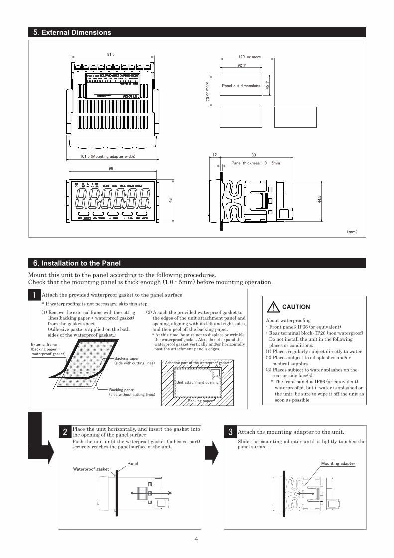
5. External Dimensions
6. Installation to the Panel
(mm)
Mount this unit to the panel according to the following procedures.Check that the mounting panel is thick enough (1.0 - 5mm) before mounting operation.
3 Attach the mounting adapter to the unit.Slide the mounting adapter until it lightly touches the panel surface.
Mounting adapter
2 Place the unit horizontally, and insert the gasket into the opening of the panel surface.Push the unit until the waterproof gasket (adhesive part) securely reaches the panel surface of the unit.
・ Front panel: IP66 (or equivalent)・ Rear terminal block: IP20 (non-waterproof) Do not install the unit in the following places or conditions.(1) Places regularly subject directly to water(2) Places subject to oil splashes and/or medical supplies(3) Places subject to water splashes on the rear or side face(s). * The front panel is IP66 (or equivalent) waterproofed, but if water is splashed on the unit, be sure to wipe it off the unit as soon as possible.
1 Attach the provided waterproof gasket to the panel surface.* If waterproofing is not necessary, skip this step.
(1) Remove the external frame with the cutting lines(backing paper + waterproof gasket) from the gasket sheet. (Adhesive paste is applied on the both sides of the waterproof gasket.)
(2) Attach the provided waterproof gasket to the edges of the unit attachment panel and opening, aligning with its left and right sides, and then peel off the backing paper.
About waterproofing
* At this time, be sure not to displace or wrinkle the waterproof gasket. Also, do not expand the waterproof gasket vertically and/or horizontally past the attachment panel’s edges.
External frame(backing paper + waterproof gasket)
Backing paper(side with cutting lines)
Backing paper(side without cutting lines)
Unit attachment opening
Backing paper
Adhesive part of the waterproof gasket
PanelWaterproof gasket
! CAUTION
5
For DT-501XA/DT-501XD
Item Description
Power AC (DT-501XA) 85 - 264VAC(50/60Hz)DC (DT-501XD) 10.8 - 25.2VDC
Consumption power 10VASensor power output DC+12V Max.100mA
Open collector input
Open collector (NPN) input
LO input Load capacity 12mA or more0 - 3V
HI input Leakage current 0.5mA or lessMaximum frequency 100kHz(Minimum pulse width 5micro second)
Contact inputFor no-voltage contact. Short-circuit ⑤ and ⑥ to use.Contact capacity Voltage 12V, Current 15mA or moreMaximum frequency 20Hz(Minimum pulse width 25micro second)
Voltage input
LO input 0 - 1.5VHI input 4.0 - 30VInput resistance 10kΩMaximum frequency 30kHz(Minimum pulse width 17micro second)
Magnetic sensor input
Input resistance 10kΩ
Input voltage1Hz ~ 100Hz 0.3 ~ 30Vp-p~ 1kHz 1.5 ~ 30Vp-p~ 10kHz 6 ~ 30Vp-p
Maximum frequency 10kHz(Minimum pulse width 50micro second)
Input signal type Sensor Our product model Connection terminalContact signal Relay switch ― 5-6-9Open collector Adjacent switch SE-P12-1 4-6-9
Square waveAdjacent switch SE-P12
4-7-9Rotary encoder RE-1-□FGear sensor SE-G2
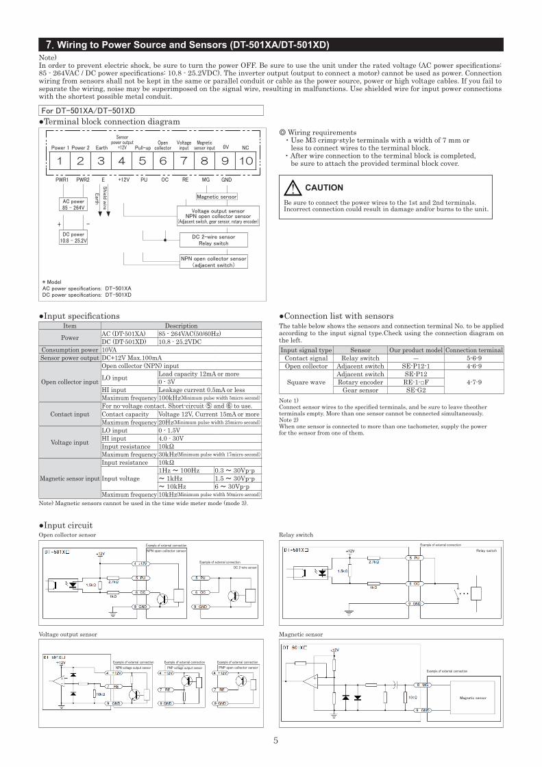
7. Wiring to Power Source and Sensors (DT-501XA/DT-501XD)
+ -
NPN open collector sensor(adjacent switch)
DC 2-wire sensorRelay switch
Voltage output sensorNPN open collector sensor
(Adjacent switch, gear sensor, rotary encoder)
Note)In order to prevent electric shock, be sure to turn the power OFF. Be sure to use the unit under the rated voltage (AC power specifi cations: 85 - 264VAC / DC power specifi cations: 10.8 - 25.2VDC). The inverter output (output to connect a motor) cannot be used as power. Connection wiring from sensors shall not be kept in the same or parallel conduit or cable as the power source, power or high voltage cables. If you fail to separate the wiring, noise may be superimposed on the signal wire, resulting in malfunctions. Use shielded wire for input power connections with the shortest possible metal conduit.
●Terminal block connection diagram
PWR1 PWR2 E PU OC RE MG GND+12V
Power 1 Power 2 Earth
Sensor power output
+12V Pull-upOpen
collectorVoltage input
Magnetic sensor input 0V NC
1 2 3 4 5 6 7 8 9 10
DC power10.8 - 25.2V
AC power85 - 264V
Magnetic sensor
* ModelAC power specifi cations: DT-501XADC power specifi cations: DT-501XD
Earth
Shie
ld wire
◎ Wiring requirements ・ Use M3 crimp-style terminals with a width of 7 mm or less to connect wires to the terminal block. ・ After wire connection to the terminal block is completed, be sure to attach the provided terminal block cover.
Be sure to connect the power wires to the 1st and 2nd terminals.Incorrect connection could result in damage and/or burns to the unit.
! CAUTION
Note) Magnetic sensors cannot be used in the time wide meter mode (mode 3).
●Input specifi cations ●Connection list with sensorsThe table below shows the sensors and connection terminal No. to be applied according to the input signal type.Check using the connection diagram on the left.
Note 1) Connect sensor wires to the specifi ed terminals, and be sure to leave theother terminals empty. More than one sensor cannot be connected simultaneously.Note 2) When one sensor is connected to more than one tachometer, supply the power for the sensor from one of them.
●Input circuitOpen collector sensor
Voltage output sensor
Relay switch
Magnetic sensor
Example of external connection Example of external connection
Example of external connection
Example of external connection Example of external connection Example of external connection
Example of external connection
NPN open collector sensor
PNP open collector sensor
DC 2-wire sensor
NPN voltage output sensor PNP voltage output sensor
Relay switch
Magnetic sensor
6
Item DescriptionPower AC (501FA) 85 - 264VAC(50/60Hz)
Consumption power 10VASensor power output DC+12V Max.100mA
Differential input
Connection to Differential line driver AM26LS31 etc.
Differential input voltage
VDIFMaximum voltage ±5.5V(15mA)Minimum voltage ±3.0V
Maximum frequency 100kHz(Minimum pulse width 5micro second)
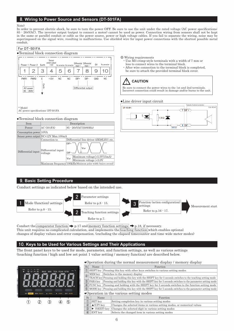
8. Wiring to Power Source and Sensors (DT-501FA)
9. Basic Setting Procedure
NCPWR1 PWR2 E NC NC DIF+ DIF- GND+12V
DIF+
VDIF
DIF-
① ② ③ ④ ⑤
Note)In order to prevent electric shock, be sure to turn the power OFF. Be sure to use the unit under the rated voltage (AC power specifications: 85 - 264VAC). The inverter output (output to connect a motor) cannot be used as power. Connection wiring from sensors shall not be kept in the same or parallel conduit or cable as the power source, power or high voltage cables. If you fail to separate the wiring, noise may be superimposed on the signal wire, resulting in malfunctions. Use shielded wire for input power connections with the shortest possible metal conduit.
For DT-501FA●Terminal block connection diagram
Power 1 Power 2 Earth
Sensor power output
+12V No connection No connectionDifferential
input +Differential
input - 0V No connection
1 2 3 4 5 6 7 8 9 10
AC power85 - 264V
Earth
Differential output
* ModelAC power specifications: DT-501FA
●Line driver input circuit
◎ Wiring requirements ・ Use M3 crimp-style terminals with a width of 7 mm or less to connect wires to the terminal block. ・ After wire connection to the terminal block is completed, be sure to attach the provided terminal block cover.
Be sure to connect the power wires to the 1st and 2nd terminals.Incorrect connection could result in damage and/or burns to the unit.
! CAUTION
Example of external connection
Line driver
●Terminal block connection diagram
Conduct the comparator function p.17 and memory function settings p.18, if necessary.This unit requires no complicated calculation, and implements the teaching function which enables optional changes of display values and error compensation. (excluding the elapsed timecounter and time wide meter modes)
Measurement start
10. Keys to be Used for Various Settings and Their Applications
Conduct settings as indicated below based on the intended use.
The front panel keys to be used for mode, parameter, and function settings, as well as various settings(teaching function / high and low set point 1 value setting / memory function) are described below.
1 Mode (function) settings
Refer to p.8 - 15.
2 Parameter settings
Refer to p.8 - 15.
2 Teaching function settings
Refer to p.7.
3 Function (action configuration) settings
Refer to p.16 - 17.
●Operation during the normal measurement display / memory display
●Operation in the various setting modes
№ Name Function① SHIFT key Pressing this key with other keys switches to various setting modes
②MEM key Switches to the memory displayTEACH key Pressing and holding this key with the SHIFT key for 5 seconds switches to the teaching setting mode
③ PARA key Pressing and holding this key with the SHIFT key for 5 seconds switches to the parameter setting mode④ FUNC key Pressing and holding with the SHIFT key for 5 seconds switches to the function setting mode⑤ MODE key Pressing and holding this key with the SHIFT key for 5 seconds switches to the parameter setting mode
№ Name Function① SET key Setting completion key in various setting modes② ▲(UP) key Changes the selected items in various setting modes, or numerical values③
▲ (NEXT) key Changes the selected digit in various setting modes④ ENT key Selects the changed item in various setting modes
7
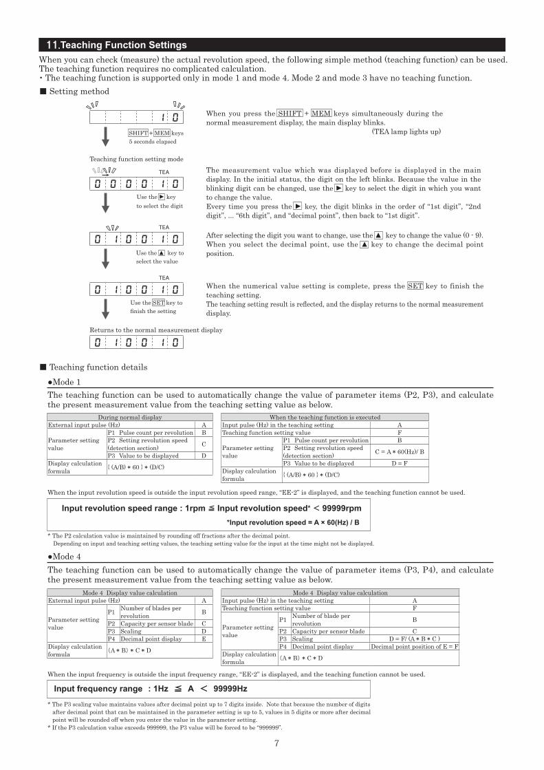
11.Teaching Function Settings
■ Setting method
SHIFT + MEM keys 5 seconds elapsed
TEA
TEA
TEA
Use the
▲
key to select the digit
Use the ▲ key to select the value
Use the SET key to finish the setting
Teaching function setting mode
Returns to the normal measurement display
When you can check (measure) the actual revolution speed, the following simple method (teaching function) can be used.The teaching function requires no complicated calculation.・The teaching function is supported only in mode 1 and mode 4. Mode 2 and mode 3 have no teaching function.
When you press the SHIFT + MEM keys simultaneously during the normal measurement display, the main display blinks. (TEA lamp lights up)
After selecting the digit you want to change, use the ▲ key to change the value (0 - 9).When you select the decimal point, use the ▲ key to change the decimal point position.
When the numerical value setting is complete, press the SET key to finish the teaching setting.The teaching setting result is reflected, and the display returns to the normal measurement display.
The measurement value which was displayed before is displayed in the main display. In the initial status, the digit on the left blinks. Because the value in the blinking digit can be changed, use the
▲
key to select the digit in which you want to change the value.Every time you press the
▲
key, the digit blinks in the order of “1st digit”, “2nd digit”, ... “6th digit”, and “decimal point”, then back to “1st digit”.
1 0
0 0 0 0 1 0
0 1 0 0 1 0
0 1 0 0 1 0
0 1 0 0 1 0
■ Teaching function details●Mode 1
●Mode 4
The teaching function can be used to automatically change the value of parameter items (P2, P3), and calculate the present measurement value from the teaching setting value as below.
The teaching function can be used to automatically change the value of parameter items (P3, P4), and calculate the present measurement value from the teaching setting value as below.
When the input revolution speed is outside the input revolution speed range, “EE-2” is displayed, and the teaching function cannot be used.
When the input frequency is outside the input frequency range, “EE-2” is displayed, and the teaching function cannot be used.
* The P2 calculation value is maintained by rounding off fractions after the decimal point. Depending on input and teaching setting values, the teaching setting value for the input at the time might not be displayed.
* The P3 scaling value maintains values after decimal point up to 7 digits inside. Note that because the number of digits after decimal point that can be maintained in the parameter setting is up to 5, values in 5 digits or more after decimal point will be rounded off when you enter the value in the parameter setting.* If the P3 calculation value exceeds 999999, the P3 value will be forced to be “999999”.
Input revolution speed range : 1rpm ≦ Input revolution speed* < 99999rpm *Input revolution speed = A × 60(Hz) / B
Input frequency range : 1Hz ≦ A < 99999Hz
During normal displayExternal input pulse (Hz) A
Parameter setting value
P1 Pulse count per revolution BP2 Setting revolution speed (detection section) C
P3 Value to be displayed DDisplay calculation formula { (A/B) * 60 } * (D/C)
Mode 4 Display value calculationExternal input pulse (Hz) A
Parameter setting value
P1 Number of blades per revolution B
P2 Capacity per sensor blade CP3 Scaling DP4 Decimal point display E
Display calculation formula (A * B) * C * D
Mode 4 Display value calculationInput pulse (Hz) in the teaching setting ATeaching function setting value F
Parameter setting value
P1 Number of blade per revolution B
P2 Capacity per sensor blade CP3 Scaling D = F/ (A * B * C )P4 Decimal point display Decimal point position of E = F
Display calculation formula (A * B) * C * D
When the teaching function is executed Input pulse (Hz) in the teaching setting ATeaching function setting value F
Parameter setting value
P1 Pulse count per revolution BP2 Setting revolution speed (detection section) C = A * 60(Hz)/ B
P3 Value to be displayed D = FDisplay calculation formula { (A/B) * 60 } * (D/C)
8
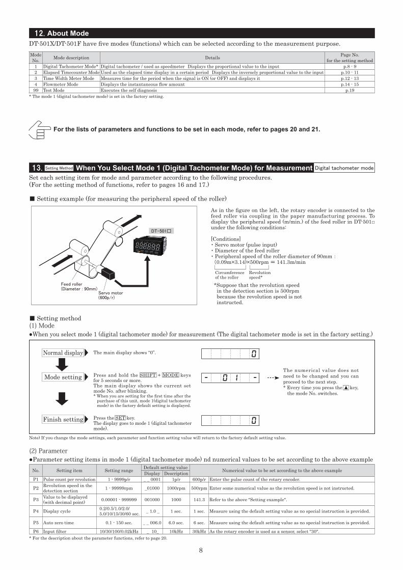
12. About Mode
13. When You Select Mode 1 (Digital Tachometer Mode) for Measurement
DT-501X/DT-501F have five modes (functions) which can be selected according to the measurement purpose.
* The mode 1 (digital tachometer mode) is set in the factory setting.
For the lists of parameters and functions to be set in each mode, refer to pages 20 and 21.
●When you select mode 1 (digital tachometer mode) for measurement (The digital tachometer mode is set in the factory setting.)
●Parameter setting items in mode 1 (digital tachometer mode) nd numerical values to be set according to the above example
Mode No. Mode description Details Page No.
for the setting method1 Digital Tachometer Mode* Digital tachometer / used as speedmeter Displays the proportional value to the input p.8 - 92 Elapsed Timecounter Mode Used as the elapsed time display in a certain period Displays the inversely proportional value to the input p.10 - 113 Time Width Meter Mode Measures time for the period when the signal is ON (or OFF) and displays it p.12 - 134 Flowmeter Mode Displays the instantaneous flow amount p.14 - 15
99 Test Mode Executes the self diagnosis p.19
Setting Method
Servo motor(600p/r)
Feed roller(Diameter : 90mm)
DT-501□
■ Setting example (for measuring the peripheral speed of the roller)
■ Setting method(1) Mode
(2) Parameter
As in the figure on the left, the rotary encoder is connected to the feed roller via coupling in the paper manufacturing process. To display the peripheral speed (m/min.) of the feed roller in DT-501□ under the following conditions:
[Conditions]・ Servo motor (pulse input)・ Diameter of the feed roller・ Peripheral speed of the roller diameter of 90mm : (0.09m×3.14)×500rpm = 141.3m/min
*Suppose that the revolution speed in the detection section is 500rpm because the revolution speed is not instructed.
Circumference of the roller
Revolution speed*
Normal display
Mode setting
Finish setting
The main display shows “0”. 0
0
- 0 1 -
Press the SET key.The display goes to mode 1 (digital tachometer mode).
The numerical value does not need to be changed and you can proceed to the next step.* Every time you press the ▲ key, the mode No. switches.
Press and hold the SHIFT + MODE keys for 5 seconds or more.The main display shows the current set mode No. after blinking.* When you are setting for the first time after the purchase of this unit, mode 1(digital tachometer mode) in the factory default setting is displayed.
Note) If you change the mode settings, each parameter and function setting value will return to the factory default setting value.
* For the description about the parameter functions, refer to page 20.
No. Setting item Setting range Default setting value Numerical value to be set according to the above exampleDisplay DescriptionP1 Pulse count per revolution 1 - 9999p/r _ _ 0001 1p/r 600p/r Enter the pulse count of the rotary encoder.
P2 Revolution speed in the detection section 1 - 99999rpm _01000 1000rpm 500rpm Enter some numerical value as the revolution speed is not instructed.
P3 Value to be displayed (with decimal point) 0.00001 - 999999 001000 1000 141.3 Refer to the above "Setting example".
P4 Display cycle 0.2/0.5/1.0/2.0/ 5.0/10/15/30/60 sec. _ 1.0 _ 1 sec. 1 sec. Measure using the default setting value as no special instruction is provided.
P5 Auto zero time 0.1 - 150 sec. _ _ 006.0 6.0 sec. 6 sec. Measure using the default setting value as no special instruction is provided.
P6 Input filter 10/30/100/0.02kHz _ 10_ 10kHz 30kHz As the rotary encoder is used as a sensor, select "30".
Set each setting item for mode and parameter according to the following procedures.(For the setting method of functions, refer to pages 16 and 17.)
Digital tachometer mode
9
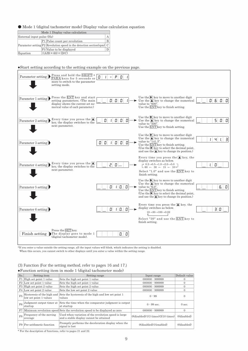
● Mode 1 (digital tachometer mode) Display value calculation equationMode 1 Display value calculation
External input pulse (Hz) A
Parameter settingP1 Pulse count per revolution BP2 Revolution speed in the detection section(rpm) CP3 Value to be displayed D
Equation ((A/B) * 60) * (D/C)
Use the ▲
key to move to another digitUse the ▲ key to change the numerical value to “600”.Use the ENT key to finish setting.
●Start setting according to the setting example on the previous page.
●Function setting item in mode 1 (digital tachometer mode)(3) Function (For the setting method, refer to pages 16 and 17.)
-- 0 0 0 1
0 1 - P 0 1
-- 0 6 0 0
1 4 1. 3 0 0 1 0 0 0
Press the ENT key and start setting parameters. (The main display shows the current set nu-merical value of each parameter.)
- 5 0 0- 0 1 0 0 0Every time you press the ▲ key, the display switches to the next parameter.
Every time you press the ▲ key, the display switches to the next parameter.
Use the
▲
key to move to another digitUse the ▲ key to change the numerical value to “500”.Use the ENT key to finish setting.
Press and hold the SHIFT + PARA keys for 5 seconds or more to switch to the parameter setting mode.
Parameter 1 setting
Parameter setting
Parameter 2 setting
Parameter 3 setting
Parameter 4 setting
Parameter 5 setting
Parameter 6 setting
*If you enter a value outside the setting range, all the input values will blink, which indicates the setting is disabled. When this occurs, you cannot switch to other displays until you enter a value within the setting range.
No. Setting item Setting range Input range Default valueF1 High set point 1 value Sets the high set point 1 value 000000 - 999999 0 F2 Low set point 1 value Sets the high set point 1 value 000000 - 999999 0 F3 High set point 2 value Sets the high set point 2 value 000000 - 999999 0 F4 Low set point 2 value Sets the low set point 2 value 000000 - 999999 0
F5 Hysteresis of the high and low set point 1 values
Sets the hysteresis of the high and low set point 1 values 0 - 99 0
F6 Judgment output timer at startup
Sets the time when the comparator judgment is outputat startup 0 - 99 sec. 0 sec.
F7 Minimum revolution speed Sets the revolution speed to be displayed as zero 000000 - 999999 0
F8 Frequency of the moving average
Used when variation of the revolution speed is large and a stable display cannot be attained 0(disabled)/1(3 times)/2(10 times) 0(disabled)
F9 Pre-arithmetic function Promptly performs the deceleration display when the signal is lost 0(disabled)/1(enabled) 0(disabled)
* For the description of functions, refer to pages 21 and 22.
0.2→0.5→1.0→2.0→5.060 ← 30 ← 15 ← 10
Every time you press the ▲ key, the display switches as below.
Select "1.0" and use the ENT key to finish setting.
- 2. 0- - 1. 0-
Use the
▲
key to move to another digitUse the ▲ key to change the numerical value to “6.0”.Use the ENT key to finish setting.(Use the
▲
key to select the decimal point, and use the ▲ key to change its position.)
-- 0 1 0. 0 -- 6. 0
Finish settingPress the SET key.The display goes to mode 1 (digital tachometer mode).
0. 0
10→30→100→0.02
Select "30" and use the ENT key to finish setting.
- 3 0 --- 0 1 0. 0
Every time you press the ▲ key, the display switches as below.
Use the
▲
key to move to another digitUse the ▲ key to change the numerical value to “141.3”.Use the ENT key to finish setting.(Use the
▲
key to select the decimal point, and use the ▲ key to change its position.)
10
5m
DT-501□
Oven
Rotary encoder
Normal display
Mode setting
Finish setting
The main display shows “0”.
Note) If you change the mode settings, each parameter, function, and high and low set point 1 setting value will return to the factory default setting value.
* For the description about the parameter functions, refer to page 20.
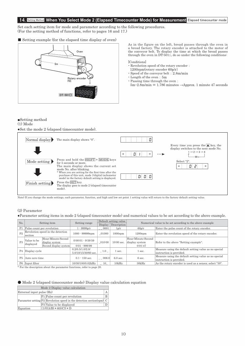
No. Setting item Setting range Default setting value Numerical value to be set according to the above exampleDisplay DescriptionP1 Pulse count per revolution 1 - 9999p/r _ _ 0001 1p/r 60p/r Enter the pulse count of the rotary encoder.
P2 Revolution speed in the detection section 1000 - 99999rpm _01000 1000rpm 1200rpm Enter the revolution speed of the rotary encoder.
P3 Value to be displayed
Hour:Minute:Second display system 0:00:01 - 9:59:59 _010:00 10:00 sec.
Hour:Minute:Second display system 0:01:47
Refer to the above "Setting example".Second display system 0:01 - 999:99
P4 Display cycle 0.2/0.5/1.0/2.0/ 5.0/10/15/30/60 sec. _ 1.0 _ 1 sec. 1 sec. Measure using the default setting value as no special
instruction is provided.
P5 Auto zero time 0.1 - 150 sec. _ _ 006.0 6.0 sec. 6 sec. Measure using the default setting value as no special instruction is provided.
P6 Input filter 10/30/100/0.02kHz _ 10_ 10kHz 30kHz As the rotary encoder is used as a sensor, select "30".
1 → 2 → 3 → 4
99
Select "2".
0
- 0 1 -
- 0 2 -
0: 0 0
Every time you press the ▲ key, the display switches to the next mode No.
■ Setting example (for the elapsed time display of oven)
Set each setting item for mode and parameter according to the following procedures.(For the setting method of functions, refer to pages 16 and 17.)
As in the figure on the left, bread passes through the oven in a bread factory. The rotary encoder is attached to the motor of the conveyor belt. To display the time at which the bread passes through the oven in DT-501□, do so under the following conditions:
[Conditions]・ Revolution speed of the rotary encoder : 1200rpm(rotary encoder 60p/r)・ Speed of the conveyor belt : 2.8m/min・ Length of the oven : 5m・ Passing time through the oven : 5m÷2.8m/min = 1.786 minutes →Approx. 1 minute 47 seconds
●Set the mode 2 (elapsed timecounter mode).
●Parameter setting items in mode 2 (elapsed timecounter mode) and numerical values to be set according to the above example.
■Setting method(1) Mode
(2) Parameter
Press and hold the SHIFT + MODE keys for 5 seconds or more.The main display shows the current set mode No. after blinking.* When you are setting for the first time after the purchase of this unit, mode 1(digital tachometer mode) in the factory default setting is displayed.Press the SET key.The display goes to mode 2 (elapsed timecountermode).
14. When You Select Mode 2 (Elapsed Timecounter Mode) for MeasurementSetting Method Elapsed timecounter mode
● Mode 2 (elapsed timecounter mode) Display value calculation equationMode 2 Display value calculation
External input pulse (Hz) A
Parameter settingP1 Pulse count per revolution BP2 Revolution speed in the detection section(rpm) CP3 Value to be displayed D
Equation (1/(((A/B) * 60)/C)) * D
11
Normal display The main display shows “0:00”.
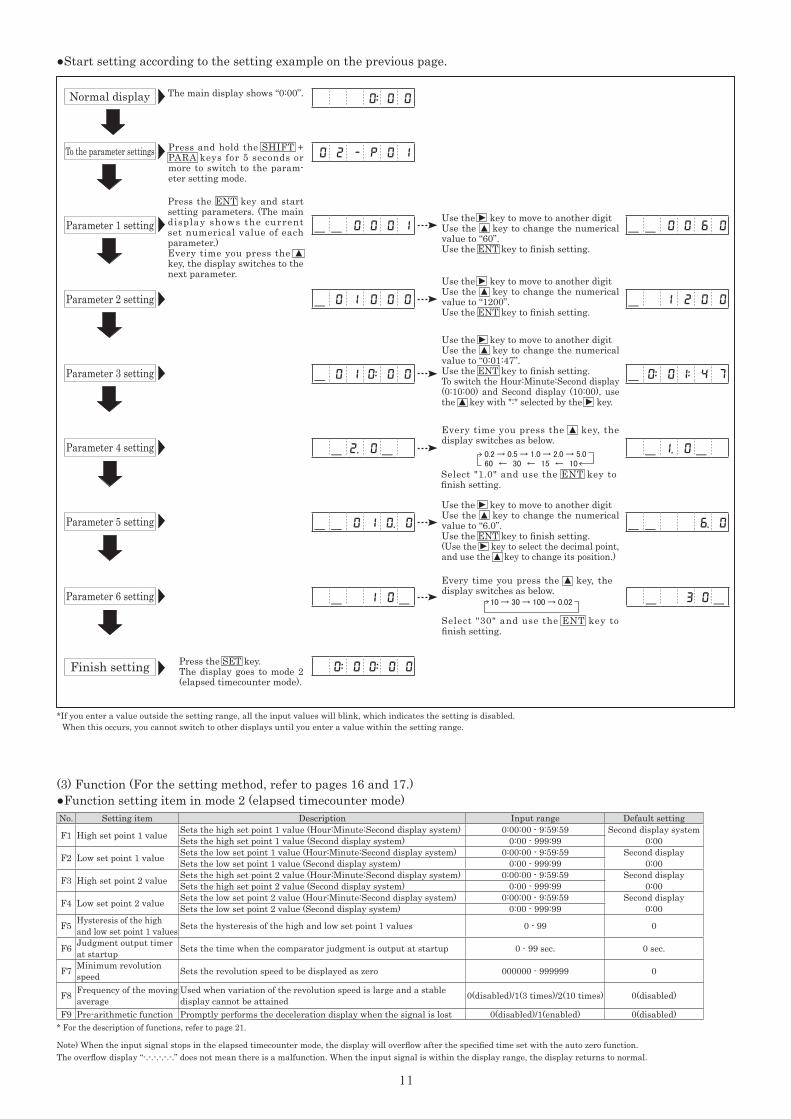
Press the ENT key and start setting parameters. (The main display shows the current set numerical value of each parameter.)Every time you press the ▲ key, the display switches to the next parameter.
Press the SET key.The display goes to mode 2 (elapsed timecounter mode).
No. Setting item Description Input range Default setting
F1 High set point 1 value Sets the high set point 1 value (Hour:Minute:Second display system) 0:00:00 - 9:59:59 Second display system0:00Sets the high set point 1 value (Second display system) 0:00 - 999:99
F2 Low set point 1 value Sets the low set point 1 value (Hour:Minute:Second display system) 0:00:00 - 9:59:59 Second display0:00Sets the low set point 1 value (Second display system) 0:00 - 999:99
F3 High set point 2 value Sets the high set point 2 value (Hour:Minute:Second display system) 0:00:00 - 9:59:59 Second display0:00Sets the high set point 2 value (Second display system) 0:00 - 999:99
F4 Low set point 2 value Sets the low set point 2 value (Hour:Minute:Second display system) 0:00:00 - 9:59:59 Second display0:00Sets the low set point 2 value (Second display system) 0:00 - 999:99
F5 Hysteresis of the high and low set point 1 values Sets the hysteresis of the high and low set point 1 values 0 - 99 0
F6 Judgment output timer at startup Sets the time when the comparator judgment is output at startup 0 - 99 sec. 0 sec.
F7 Minimum revolution speed Sets the revolution speed to be displayed as zero 000000 - 999999 0
F8 Frequency of the moving average
Used when variation of the revolution speed is large and a stable display cannot be attained 0(disabled)/1(3 times)/2(10 times) 0(disabled)
F9 Pre-arithmetic function Promptly performs the deceleration display when the signal is lost 0(disabled)/1(enabled) 0(disabled)* For the description of functions, refer to page 21.
Note) When the input signal stops in the elapsed timecounter mode, the display will overflow after the specified time set with the auto zero function. The overflow display “-.-.-.-.-.-.” does not mean there is a malfunction. When the input signal is within the display range, the display returns to normal.
0: 0 0
0 2 - P 0 1
-- 0 0 6 0
-- 6. 0
- 1 2 0 0
- 0: 0 1: 4 7
-- 0 0 0 1
- 0 1 0 0 0
- 0 1 0: 0 0
- 2. 0- - 1. 0-
-- 0 1 0. 0
0: 0 0: 0 0
- 1 0- - 3 0-
Press and hold the SHIFT + PARA keys for 5 seconds or more to switch to the param-eter setting mode.
0.2 → 0.5 → 1.0 → 2.0 → 5.060 ← 30 ← 15 ← 10
10 → 30 → 100 → 0.02
●Function setting item in mode 2 (elapsed timecounter mode)(3) Function (For the setting method, refer to pages 16 and 17.)
●Start setting according to the setting example on the previous page.
Parameter 1 setting
To the parameter settings
Parameter 2 setting
Parameter 3 setting
Parameter 4 setting
Parameter 5 setting
Parameter 6 setting
Finish setting
Use the
▲
key to move to another digitUse the ▲ key to change the numerical value to “60”.Use the ENT key to finish setting.
Use the
▲
key to move to another digitUse the ▲ key to change the numerical value to “1200”.Use the ENT key to finish setting.
*If you enter a value outside the setting range, all the input values will blink, which indicates the setting is disabled. When this occurs, you cannot switch to other displays until you enter a value within the setting range.
Every time you press the ▲ key, the display switches as below.
Select "1.0" and use the ENT key to finish setting.
Select "30" and use the ENT key to finish setting.
Every time you press the ▲ key, the display switches as below.
Use the
▲
key to move to another digitUse the ▲ key to change the numerical value to “0:01:47”.Use the ENT key to finish setting.To switch the Hour:Minute:Second display (0:10:00) and Second display (10:00), use the ▲ key with ":" selected by the
▲
key.
Use the
▲
key to move to another digitUse the ▲ key to change the numerical value to “6.0”.Use the ENT key to finish setting.(Use the
▲
key to select the decimal point, and use the ▲ key to change its position.)
12
Adjacent switchSE-P12-1
DT-501□
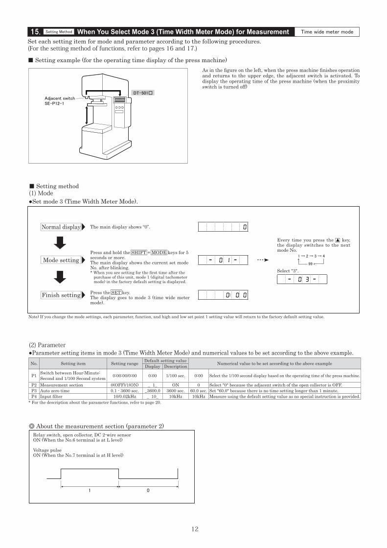
15. When You Select Mode 3 (Time Width Meter Mode) for MeasurementSetting Method Time wide meter mode
Set each setting item for mode and parameter according to the following procedures.(For the setting method of functions, refer to pages 16 and 17.)
■ Setting example (for the operating time display of the press machine)As in the figure on the left, when the press machine finishes operation and returns to the upper edge, the adjacent switch is activated. To display the operating time of the press machine (when the proximity switch is turned off)
Normal display
Mode setting
Finish setting
The main display shows “0”.
Press the SET key.The display goes to mode 3 (time wide meter mode).
Note) If you change the mode settings, each parameter, function, and high and low set point 1 setting value will return to the factory default setting value.
* For the description about the parameter functions, refer to page 20.
No. Setting item Setting range Default setting value Numerical value to be set according to the above exampleDisplay Description
P1 Switch between Hour:Minute:Second and 1/100 Second system 0:00:00/0:00 0:00 1/100 sec. 0:00 Select the 1/100 second display based on the operating time of the press machine.
P2 Measurement section 0(OFF)/1(ON) _ 1_ ON 0 Select "0" because the adjacent switch of the open collector is OFF.P3 Auto zero time 0.1 - 3600 sec. _3600.0 3600 sec. 60.0 sec. Set "60.0" because there is no time setting longer than 1 minute.P4 Input filter 10/0.02kHz _ 10_ 10kHz 10kHz Measure using the default setting value as no special instruction is provided.
Relay switch, open collector, DC 2-wire sensorON (When the No.6 terminal is at L level)
Voltage pulseON (When the No.7 terminal is at H level)
◎ About the measurement section (parameter 2)
1 0
0
- 0 1 -
Every time you press the ▲ key, the display switches to the next mode No.
1 → 2 → 3 → 4
99
Select "3".
- 0 3 -
0: 0 0
Press and hold the SHIFT + MODE keys for 5 seconds or more.The main display shows the current set mode No. after blinking.* When you are setting for the first time after the purchase of this unit, mode 1 (digital tachometer mode) in the factory default setting is displayed.
●Set mode 3 (Time Width Meter Mode).
■ Setting method(1) Mode
●Parameter setting items in mode 3 (Time Width Meter Mode) and numerical values to be set according to the above example.(2) Parameter
13
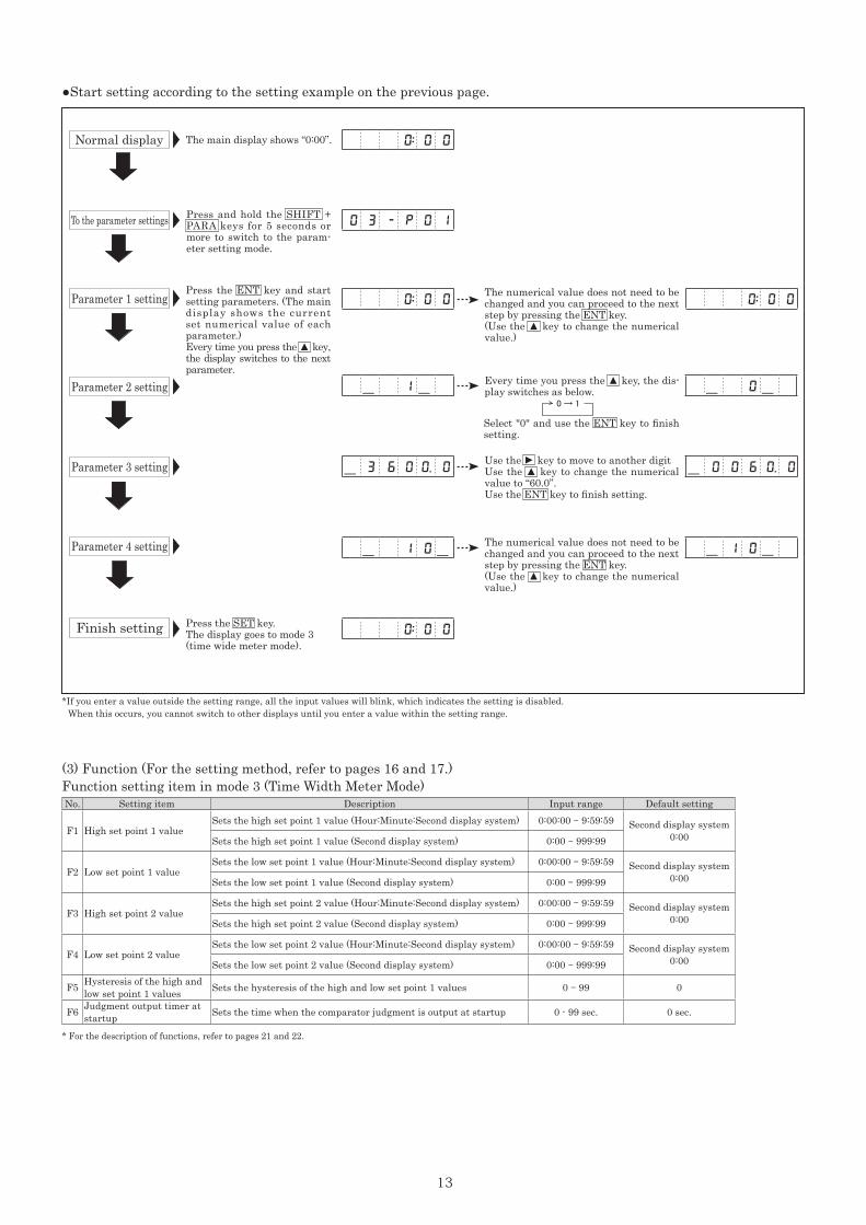
The main display shows “0:00”.
Press the ENT key and start setting parameters. (The main display shows the current set numerical value of each parameter.)Every time you press the ▲ key, the display switches to the next parameter.
Press the SET key.The display goes to mode 3 (time wide meter mode).
0: 0 0
0: 0 0 0: 0 0
0: 0 0
0 3 - P 0 1
- 0 0 6 0. 0- 3 6 0 0. 0
- 1 0- - 1 0-
- 1 - - 0-
Press and hold the SHIFT + PARA keys for 5 seconds or more to switch to the param-eter setting mode.
The numerical value does not need to be changed and you can proceed to the next step by pressing the ENT key.(Use the ▲ key to change the numerical value.)
The numerical value does not need to be changed and you can proceed to the next step by pressing the ENT key.(Use the ▲ key to change the numerical value.)
Use the
▲
key to move to another digitUse the ▲ key to change the numerical value to “60.0”.Use the ENT key to finish setting.
Every time you press the ▲ key, the dis-play switches as below.
Select "0" and use the ENT key to finish setting.
0 → 1
No. Setting item Description Input range Default setting
F1 High set point 1 valueSets the high set point 1 value (Hour:Minute:Second display system) 0:00:00 - 9:59:59 Second display system
0:00Sets the high set point 1 value (Second display system) 0:00 - 999:99
F2 Low set point 1 valueSets the low set point 1 value (Hour:Minute:Second display system) 0:00:00 - 9:59:59 Second display system
0:00Sets the low set point 1 value (Second display system) 0:00 - 999:99
F3 High set point 2 valueSets the high set point 2 value (Hour:Minute:Second display system) 0:00:00 - 9:59:59 Second display system
0:00Sets the high set point 2 value (Second display system) 0:00 - 999:99
F4 Low set point 2 valueSets the low set point 2 value (Hour:Minute:Second display system) 0:00:00 - 9:59:59 Second display system
0:00Sets the low set point 2 value (Second display system) 0:00 - 999:99
F5 Hysteresis of the high and low set point 1 values Sets the hysteresis of the high and low set point 1 values 0 - 99 0
F6 Judgment output timer at startup Sets the time when the comparator judgment is output at startup 0 - 99 sec. 0 sec.
* For the description of functions, refer to pages 21 and 22.
●Start setting according to the setting example on the previous page.
Normal display
Parameter 1 setting
To the parameter settings
Parameter 2 setting
Parameter 3 setting
Parameter 4 setting
Finish setting
*If you enter a value outside the setting range, all the input values will blink, which indicates the setting is disabled. When this occurs, you cannot switch to other displays until you enter a value within the setting range.
Function setting item in mode 3 (Time Width Meter Mode)(3) Function (For the setting method, refer to pages 16 and 17.)
14
DT-501□
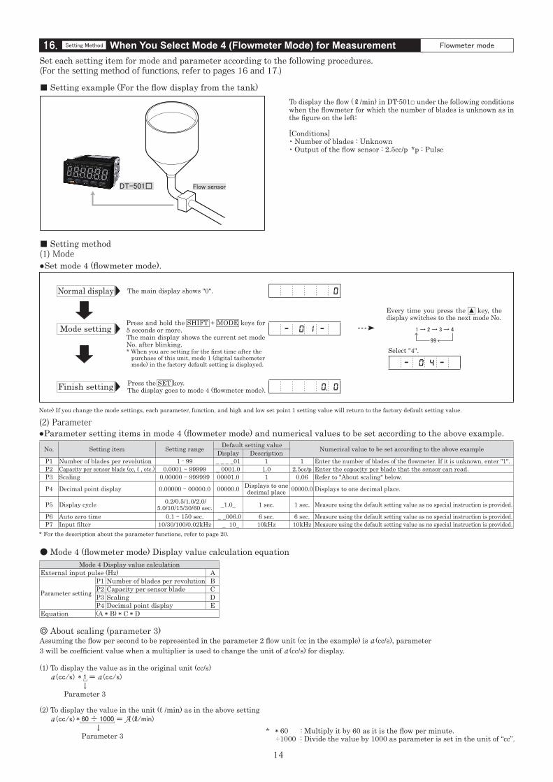
Mode 4 Display value calculationExternal input pulse (Hz) A
Parameter setting
P1 Number of blades per revolution BP2 Capacity per sensor blade CP3 Scaling DP4 Decimal point display E
Equation (A * B) * C * D
16. When You Select Mode 4 (Flowmeter Mode) for MeasurementSetting Method Flowmeter mode
Flow sensor
Set each setting item for mode and parameter according to the following procedures.(For the setting method of functions, refer to pages 16 and 17.)
■ Setting example (For the flow display from the tank)To display the flow ( ℓ /min) in DT-501□ under the following conditions when the flowmeter for which the number of blades is unknown as in the figure on the left:
[Conditions]・ Number of blades : Unknown ・ Output of the flow sensor : 2.5cc/p *p : Pulse
Normal display
Mode setting
Finish setting
The main display shows "0".
No. Setting item Setting range Default setting value Numerical value to be set according to the above exampleDisplay DescriptionP1 Number of blades per revolution 1 - 99 _ _ _ _01 1 1 Enter the number of blades of the flowmeter. If it is unknown, enter "1".P2 Capacity per sensor blade (cc, ℓ , etc.) 0.0001 - 99999 _ 0001.0 1.0 2.5cc/p Enter the capacity per blade that the sensor can read.P3 Scaling 0.00000 - 999999 00001.0 1 0.06 Refer to "About scaling" below.
P4 Decimal point display 0.00000 - 00000.0 00000.0 Displays to one decimal place 00000.0 Displays to one decimal place.
P5 Display cycle 0.2/0.5/1.0/2.0/5.0/10/15/30/60 sec. _1.0_ 1 sec. 1 sec. Measure using the default setting value as no special instruction is provided.
P6 Auto zero time 0.1 - 150 sec. _ _006.0 6 sec. 6 sec. Measure using the default setting value as no special instruction is provided.P7 Input filter 10/30/100/0.02kHz _ 10_ 10kHz 10kHz Measure using the default setting value as no special instruction is provided.
0
- 0 1 -
0. 0
Press and hold the SHIFT + MODE keys for 5 seconds or more.The main display shows the current set mode No. after blinking.* When you are setting for the first time after the purchase of this unit, mode 1 (digital tachometer mode) in the factory default setting is displayed.
Every time you press the ▲ key, the display switches to the next mode No.
1 → 2 → 3 → 4
99
Select "4".
- 0 4 -
Note) If you change the mode settings, each parameter, function, and high and low set point 1 setting value will return to the factory default setting value.
●Set mode 4 (flowmeter mode).
■ Setting method(1) Mode
Press the SET key.The display goes to mode 4 (flowmeter mode).
* For the description about the parameter functions, refer to page 20.
●Parameter setting items in mode 4 (flowmeter mode) and numerical values to be set according to the above example.(2) Parameter
◎ About scaling (parameter 3)Assuming the flow per second to be represented in the parameter 2 flow unit (cc in the example) is a (cc/s), parameter 3 will be coefficient value when a multiplier is used to change the unit of a (cc/s) for display.
(1) To display the value as in the original unit (cc/s) a (cc/s) * 1 = a (cc/s)
↓ Parameter 3
(2) To display the value in the unit (ℓ /min) as in the above setting a (cc/s) * 60 ÷ 1000 = A (ℓ/min)
↓ Parameter 3 * * 60 : Multiply it by 60 as it is the flow per minute.
÷1000 : Divide the value by 1000 as parameter is set in the unit of “cc”.
● Mode 4 (flowmeter mode) Display value calculation equation
15
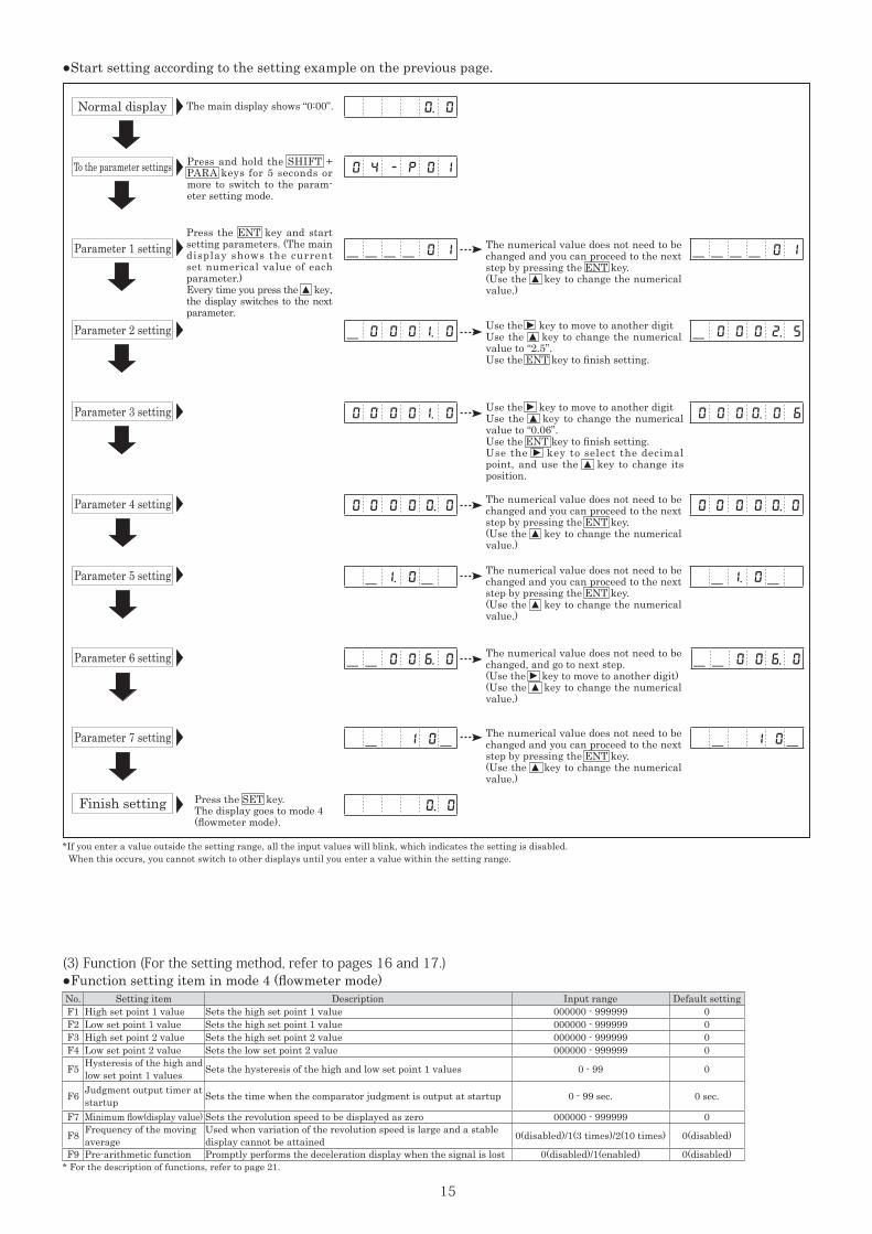
Press the SET key.The display goes to mode 4 (flowmeter mode).
0. 0
0 4 - P 0 1
---- 0 1
- 1. 0-
- 0 0 0 2. 5
0 0 0 0. 0 6
---- 0 1
- 0 0 0 1. 0
0 0 0 0 1. 0
0 0 0 0 0. 0 0 0 0 0 0. 0
- 1. 0-
- 1 0- - 1 0-
0. 0
-- 0 0 6. 0 -- 0 0 6. 0
No. Setting item Description Input range Default settingF1 High set point 1 value Sets the high set point 1 value 000000 - 999999 0 F2 Low set point 1 value Sets the high set point 1 value 000000 - 999999 0 F3 High set point 2 value Sets the high set point 2 value 000000 - 999999 0 F4 Low set point 2 value Sets the low set point 2 value 000000 - 999999 0
F5 Hysteresis of the high and low set point 1 values Sets the hysteresis of the high and low set point 1 values 0 - 99 0
F6 Judgment output timer at startup Sets the time when the comparator judgment is output at startup 0 - 99 sec. 0 sec.
F7 Minimum flow(display value) Sets the revolution speed to be displayed as zero 000000 - 999999 0
F8 Frequency of the moving average
Used when variation of the revolution speed is large and a stable display cannot be attained 0(disabled)/1(3 times)/2(10 times) 0(disabled)
F9 Pre-arithmetic function Promptly performs the deceleration display when the signal is lost 0(disabled)/1(enabled) 0(disabled)* For the description of functions, refer to page 21.
Use the
▲
key to move to another digitUse the ▲ key to change the numerical value to “0.06”.Use the ENT key to finish setting.Use the
▲
key to select the decimal point, and use the ▲ key to change its position.
●Start setting according to the setting example on the previous page.
Normal display
Parameter 1 setting
To the parameter settings
Parameter 2 setting
Parameter 3 setting
Parameter 4 setting
Parameter 5 setting
Parameter 6 setting
Parameter 7 setting
Finish setting
The main display shows “0:00”.
Press the ENT key and start setting parameters. (The main display shows the current set numerical value of each parameter.)Every time you press the ▲ key, the display switches to the next parameter.
Press and hold the SHIFT + PARA keys for 5 seconds or more to switch to the param-eter setting mode.
The numerical value does not need to be changed and you can proceed to the next step by pressing the ENT key.(Use the ▲ key to change the numerical value.)
The numerical value does not need to be changed and you can proceed to the next step by pressing the ENT key.(Use the ▲ key to change the numerical value.)
The numerical value does not need to be changed and you can proceed to the next step by pressing the ENT key.(Use the ▲ key to change the numerical value.)
The numerical value does not need to be changed and you can proceed to the next step by pressing the ENT key.(Use the ▲ key to change the numerical value.)
The numerical value does not need to be changed, and go to next step.(Use the
▲
key to move to another digit)(Use the ▲ key to change the numerical value.)
Use the ▲
key to move to another digitUse the ▲ key to change the numerical value to “2.5”.Use the ENT key to finish setting.
●Function setting item in mode 4 (flowmeter mode)(3) Function (For the setting method, refer to pages 16 and 17.)
*If you enter a value outside the setting range, all the input values will blink, which indicates the setting is disabled. When this occurs, you cannot switch to other displays until you enter a value within the setting range.
16Continued on next page
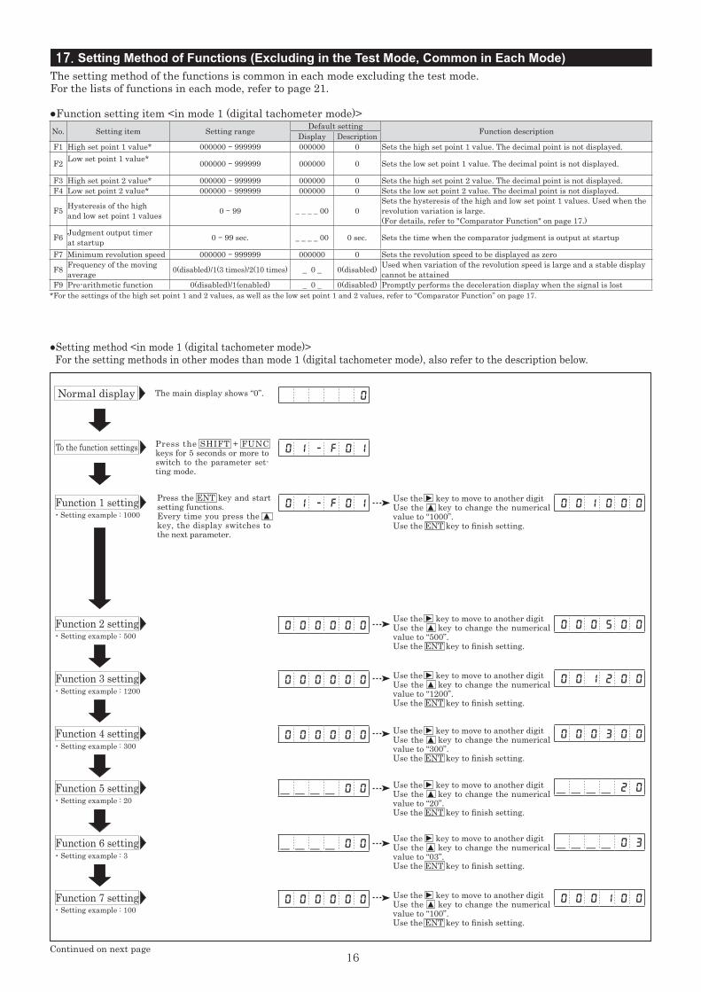
・ Setting example : 1000
・ Setting example : 500
・ Setting example : 1200
・ Setting example : 300
・ Setting example : 20
・ Setting example : 3
・ Setting example : 100
Normal display
Function 1 setting
Function 2 setting
Function 3 setting
Function 4 setting
Function 5 setting
Function 6 setting
Function 7 setting
●Function setting item <in mode 1 (digital tachometer mode)>No. Setting item Setting range Default setting Function descriptionDisplay DescriptionF1 High set point 1 value* 000000 - 999999 000000 0 Sets the high set point 1 value. The decimal point is not displayed.
F2 Low set point 1 value* 000000 - 999999 000000 0 Sets the low set point 1 value. The decimal point is not displayed.
F3 High set point 2 value* 000000 - 999999 000000 0 Sets the high set point 2 value. The decimal point is not displayed.F4 Low set point 2 value* 000000 - 999999 000000 0 Sets the low set point 2 value. The decimal point is not displayed.
F5 Hysteresis of the high and low set point 1 values 0 - 99 _ _ _ _ 00 0
Sets the hysteresis of the high and low set point 1 values. Used when the revolution variation is large.(For details, refer to "Comparator Function" on page 17.)
F6 Judgment output timerat startup 0 - 99 sec. _ _ _ _ 00 0 sec. Sets the time when the comparator judgment is output at startup
F7 Minimum revolution speed 000000 - 999999 000000 0 Sets the revolution speed to be displayed as zero
F8 Frequency of the moving average 0(disabled)/1(3 times)/2(10 times) _ 0 _ 0(disabled) Used when variation of the revolution speed is large and a stable display
cannot be attainedF9 Pre-arithmetic function 0(disabled)/1(enabled) _ 0 _ 0(disabled) Promptly performs the deceleration display when the signal is lost
*For the settings of the high set point 1 and 2 values, as well as the low set point 1 and 2 values, refer to “Comparator Function” on page 17.
To the function settings
The main display shows “0”. 0
0 1 - F 0 1
0 1 - F 0 1 0 0 1 0 0 0
0 0 0 5 0 0
0 0 1 2 0 0
0 0 0 3 0 0
0 0 0 1 0 0
---- 2 0
---- 0 3
0 0 0 0 0 0
0 0 0 0 0 0
0 0 0 0 0 0
0 0 0 0 0 0
---- 0 0
---- 0 0
Press the SHIFT + FUNC keys for 5 seconds or more to switch to the parameter set-ting mode.
Press the ENT key and start setting functions.Every time you press the ▲ key, the display switches to the next parameter.
17. Setting Method of Functions (Excluding in the Test Mode, Common in Each Mode)The setting method of the functions is common in each mode excluding the test mode.For the lists of functions in each mode, refer to page 21.
●Setting method <in mode 1 (digital tachometer mode)> For the setting methods in other modes than mode 1 (digital tachometer mode), also refer to the description below.
Use the
▲
key to move to another digitUse the ▲ key to change the numerical value to “1000”.Use the ENT key to finish setting.
Use the
▲
key to move to another digitUse the ▲ key to change the numerical value to “500”.Use the ENT key to finish setting.
Use the
▲
key to move to another digitUse the ▲ key to change the numerical value to “1200”.Use the ENT key to finish setting.
Use the
▲
key to move to another digitUse the ▲ key to change the numerical value to “300”.Use the ENT key to finish setting.
Use the
▲
key to move to another digitUse the ▲ key to change the numerical value to “20”.Use the ENT key to finish setting.
Use the
▲
key to move to another digitUse the ▲ key to change the numerical value to “03”.Use the ENT key to finish setting.
Use the
▲
key to move to another digitUse the ▲ key to change the numerical value to “100”.Use the ENT key to finish setting.
17
18. Comparator Function
Continued from previous page
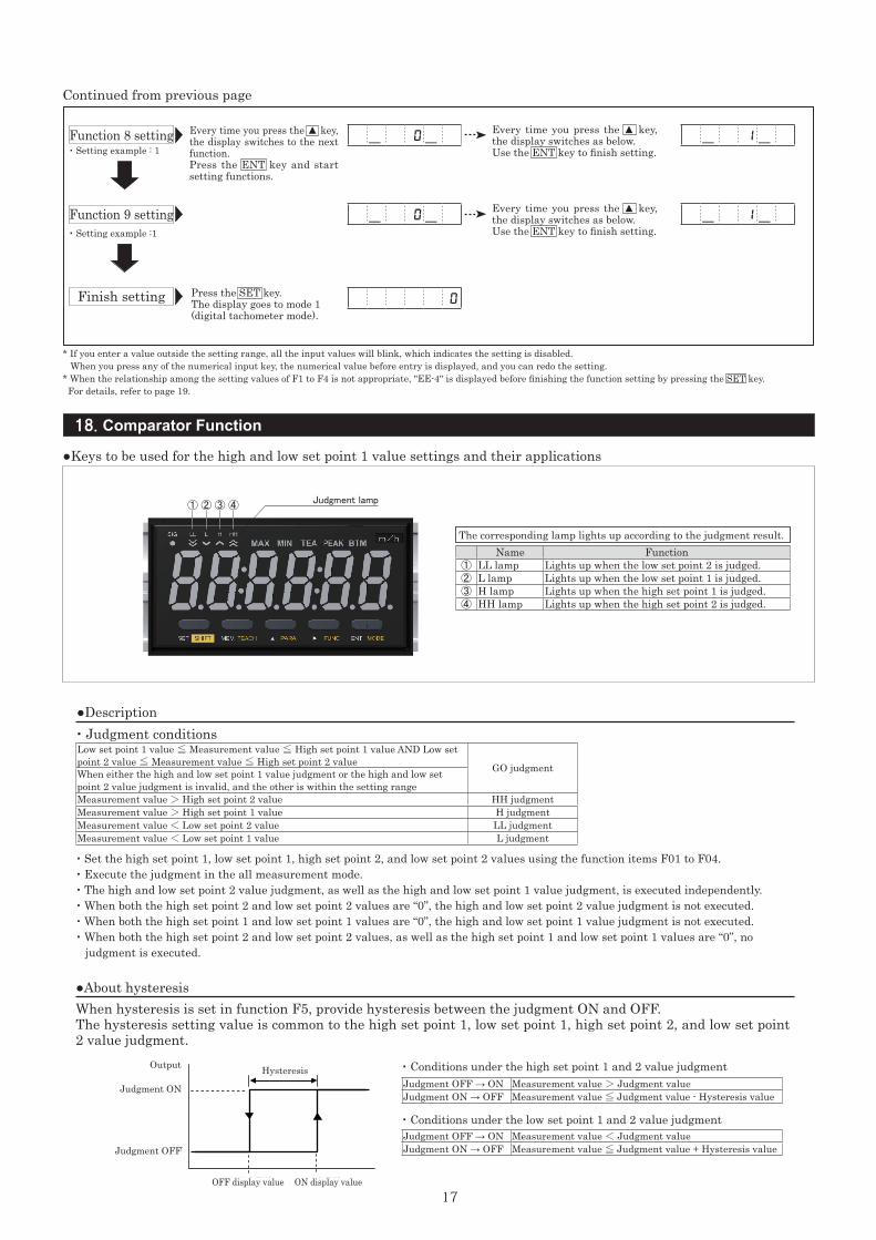
Every time you press the ▲ key, the display switches to the next function.Press the ENT key and start setting functions.
Press the SET key.The display goes to mode 1 (digital tachometer mode).
* If you enter a value outside the setting range, all the input values will blink, which indicates the setting is disabled. When you press any of the numerical input key, the numerical value before entry is displayed, and you can redo the setting.* When the relationship among the setting values of F1 to F4 is not appropriate, "EE-4" is displayed before finishing the function setting by pressing the SET key. For details, refer to page 19.
- 0-
- 0-
0
- 1-
- 1-
Every time you press the ▲ key, the display switches as below.Use the ENT key to finish setting.
Every time you press the ▲ key, the display switches as below.Use the ENT key to finish setting.
・ Setting example : 1
・ Setting example :1
Function 8 setting
Function 9 setting
Finish setting
The corresponding lamp lights up according to the judgment result.Name Function
① LL lamp Lights up when the low set point 2 is judged.② L lamp Lights up when the low set point 1 is judged.③ H lamp Lights up when the high set point 1 is judged.④ HH lamp Lights up when the high set point 2 is judged.
Judgment OFF → ON Measurement value > Judgment valueJudgment ON → OFF Measurement value ≦ Judgment value - Hysteresis value
Judgment OFF → ON Measurement value < Judgment valueJudgment ON → OFF Measurement value ≦ Judgment value + Hysteresis value
●Description
●About hysteresis
・ Conditions under the high set point 1 and 2 value judgment
・ Conditions under the low set point 1 and 2 value judgment
・ Judgment conditions
・ Set the high set point 1, low set point 1, high set point 2, and low set point 2 values using the function items F01 to F04.・ Execute the judgment in the all measurement mode.・ The high and low set point 2 value judgment, as well as the high and low set point 1 value judgment, is executed independently.・ When both the high set point 2 and low set point 2 values are “0”, the high and low set point 2 value judgment is not executed.・ When both the high set point 1 and low set point 1 values are “0”, the high and low set point 1 value judgment is not executed.・ When both the high set point 2 and low set point 2 values, as well as the high set point 1 and low set point 1 values are “0”, no judgment is executed.
When hysteresis is set in function F5, provide hysteresis between the judgment ON and OFF.The hysteresis setting value is common to the high set point 1, low set point 1, high set point 2, and low set point 2 value judgment.
Low set point 1 value ≦ Measurement value ≦ High set point 1 value AND Low set point 2 value ≦ Measurement value ≦ High set point 2 value GO judgmentWhen either the high and low set point 1 value judgment or the high and low set point 2 value judgment is invalid, and the other is within the setting rangeMeasurement value > High set point 2 value HH judgmentMeasurement value > High set point 1 value H judgmentMeasurement value < Low set point 2 value LL judgmentMeasurement value < Low set point 1 value L judgment
出力
OFF 表示値 ON 表示値
ヒステリシス
判定 ON
判定 OFF
●Keys to be used for the high and low set point 1 value settings and their applications
Output
Judgment ON
Judgment OFF
OFF display value ON display value
Hysteresis
Judgment lamp① ② ③ ④
18
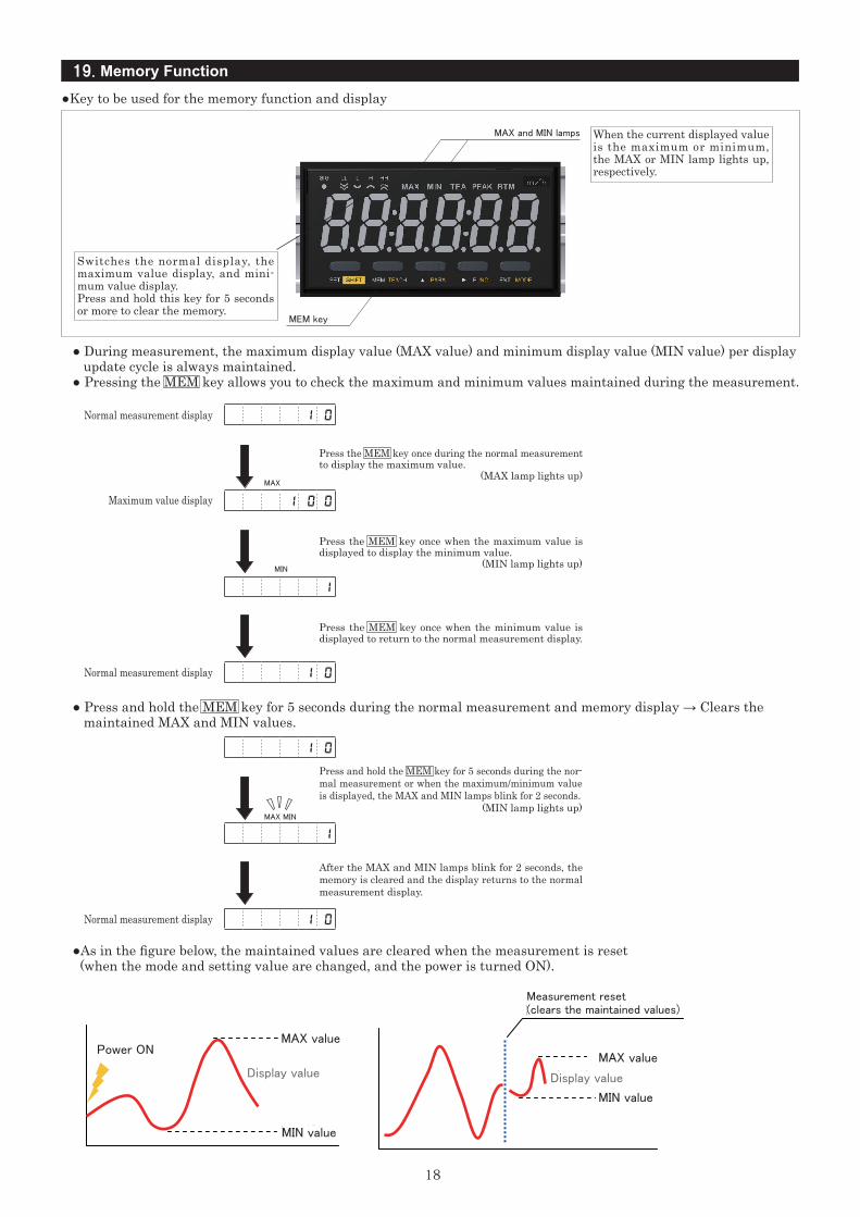
19. Memory Function
When the current displayed value is the maximum or minimum, the MAX or MIN lamp lights up, respectively.
Switches the normal display, the maximum value display, and mini-mum value display.Press and hold this key for 5 seconds or more to clear the memory.
● During measurement, the maximum display value (MAX value) and minimum display value (MIN value) per display update cycle is always maintained.● Pressing the MEM key allows you to check the maximum and minimum values maintained during the measurement.
● Press and hold the MEM key for 5 seconds during the normal measurement and memory display → Clears the maintained MAX and MIN values.
●As in the figure below, the maintained values are cleared when the measurement is reset (when the mode and setting value are changed, and the power is turned ON).
MAX and MIN lamps
MEM key
MAX
MIN
MAX MIN
Normal measurement display
Normal measurement display
Normal measurement display
Maximum value display
Press the MEM key once during the normal measurement to display the maximum value. (MAX lamp lights up)
Press the MEM key once when the maximum value is displayed to display the minimum value. (MIN lamp lights up)
Press and hold the MEM key for 5 seconds during the nor-mal measurement or when the maximum/minimum value is displayed, the MAX and MIN lamps blink for 2 seconds. (MIN lamp lights up)
After the MAX and MIN lamps blink for 2 seconds, the memory is cleared and the display returns to the normal measurement display.
Press the MEM key once when the minimum value is displayed to return to the normal measurement display.
1 0
1 0
1 0
1 0 0
1 0
1
1
電源 ON MAX 値
MIN 値
表示値
MIN 値
MAX 値
表示値
計測リセット(保持値クリア)
●Key to be used for the memory function and display
Power ONMAX value
MAX value
MIN value
MIN value
Display value Display value
Measurement reset (clears the maintained values)
19
Press the ENT key to return to the LED display test.
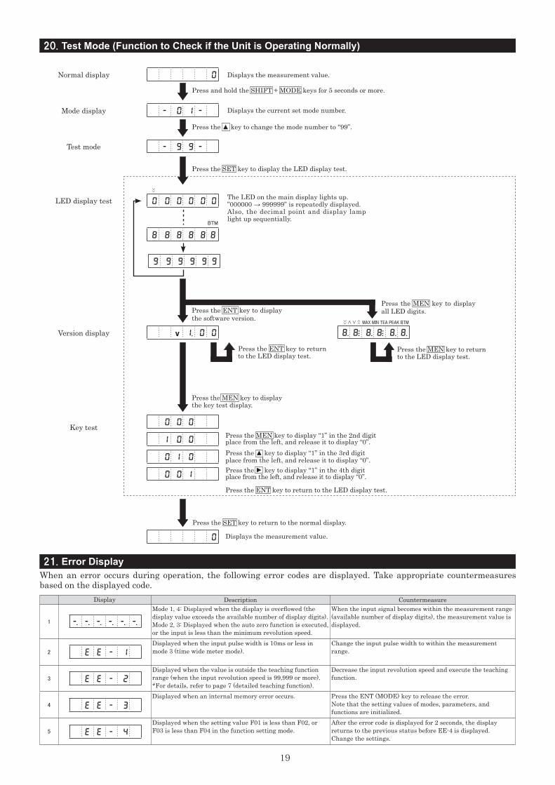
Display Description Countermeasure
1
Mode 1, 4: Displayed when the display is overflowed (the display value exceeds the available number of display digits).Mode 2, 3: Displayed when the auto zero function is executed, or the input is less than the minimum revolution speed.
When the input signal becomes within the measurement range (available number of display digits), the measurement value is displayed.
2
Displayed when the input pulse width is 10ms or less in mode 3 (time wide meter mode).
Change the input pulse width to within the measurement range.
3
Displayed when the value is outside the teaching function range (when the input revolution speed is 99,999 or more).*For details, refer to page 7 (detailed teaching function).
Decrease the input revolution speed and execute the teaching function.
4
Displayed when an internal memory error occurs. Press the ENT (MODE) key to release the error.Note that the setting values of modes, parameters, and functions are initialized.
5
Displayed when the setting value F01 is less than F02, or F03 is less than F04 in the function setting mode.
After the error code is displayed for 2 seconds, the display returns to the previous status before EE-4 is displayed.Change the settings.
-. -. -. -. -. -.
E E - 1
E E - 2
E E - 3
E E - 4
BTM
<<
> < >>
<<
MAX MIN TEA PEAK BTM
Normal display
LED display test
Key test
Version display
Mode display
Test mode
Press and hold the SHIFT + MODE keys for 5 seconds or more.
Press the ▲ key to change the mode number to “99”.
Press the SET key to display the LED display test.
Press the ENT key to display the software version.
Press the MEN key to display all LED digits.
Press the MEN key to display the key test display.
Press the SET key to return to the normal display.
Press the MEN key to display “1” in the 2nd digitplace from the left, and release it to display “0”.Press the ▲ key to display “1” in the 3rd digitplace from the left, and release it to display “0”.Press the
▲
key to display “1” in the 4th digitplace from the left, and release it to display “0”.
Displays the measurement value.
Press the ENT key to return to the LED display test.
Press the MEN key to returnto the LED display test.
Displays the measurement value.
Displays the current set mode number.
The LED on the main display lights up.”000000 → 999999” is repeatedly displayed.Also, the decimal point and display lamp light up sequentially.
0
0 0 0 0 0 0
0 0 0
1 0 0
0 1 0
0 0 1
0
8 8 8 8 8 8
8. 8:. 8. 8:. 8. 8.
9 9 9 9 9 9
v 1. 0 0
- 0 1 -
- 9 9 -
20. Test Mode (Function to Check if the Unit is Operating Normally)
21. Error DisplayWhen an error occurs during operation, the following error codes are displayed. Take appropriate countermeasures based on the displayed code.
20
Parameters in mode 1 (Digital Tachometer Mode)
Parameters in mode 2 (Elapsed Timecounter Mode)
Parameters in mode 4 (Flowmeter Mode)
Parameters in mode 3 (Time width meter Mode)
No. Setting item Description Input range Default valueP1 Pulse count per revolution Enter the pulse count per revolution for the rotary encoder, etc. 1 - 9999 P/r 1P/r
P2 Setting revolution speed(detection section) Revolution speed in the detection section 1 - 99999rpm 1000rpm
P3 Value to be displayed(with decimal point)
Actual value to be displayed on the panel in the above revolution speed 0.00001 - 999999rpm 1000rpm
P4 Display cycle Sets the display update cycle 0.2/0.5/1.0/2.0/5.0/10/15/30/60 sec. 1.0
P5 Auto zero time*1 Sets the time from when the input pulse is gone to when the display becomes "0". 0.1 - 150 sec. 6.0 sec.
P6 Input filter*2 Selects a minimum frequency that is larger than the maximum frequency of the input signal. 0.02kHz for the contact input 10/30/100/0.02kHz 10kHz
No. Setting item Description Input range Default valueP1 Pulse count per revolution Enter the pulse count per revolution for the rotary encoder, etc. 1 - 9999 P/r 1P/r
P2 Setting revolution speed(detection section) Revolution speed in the detection section 1 - 99999rpm 1000rpm
P3
Value to be displayed(Hour:Minute:Second displaysystem) Actual value to be displayed on the panel in the above
revolution speed
0:00:01 - 9:59:59 10:00(second display
system)Value to be displayed (second display system) 0:01 - 999:99
P4 Display cycle Sets the display update cycle 0.2/0.5/1.0/2.0/5.0/10/15/30/60 sec. 1 sec.
P5 Auto zero time*1 Sets the time from when the input pulse is gone to when the display becomes "0". 0.1 - 150 sec. 6 sec.
P6 Input filter*2 Selects a minimum frequency that is larger than the maximum frequency of the input signal. 0.02kHz for the contact input 10/30/100/0.02kHz 10kHz
No. Setting item Description Input range Default value
P1 Number of blades perrevolution Sets the number of blades per revolution 1 - 99 (1 when the number is unknown) 1
P2 Capacity per sensor blade (cc, ℓ, etc.) Enter the capacity per blade that the sensor can read. 0.0001 - 99999 1.0
P3 Scaling Unit coefficient value 0.00000 - 999999 1P4 Decimal point display Designates the decimal point position 0.00000 - 00000.0 00000.0P5 Display cycle Sets the display update cycle 0.2/0.5/1.0/2.0/5.0/10/15/30/60 sec. 1 sec.
P6 Auto zero time*1 Sets the time from when the input pulse is gone to when the display becomes "0". 0.1 - 150 sec. 6 sec.
P7 Input filter*2Selects a minimum frequency that is larger than the maximum frequency of the input signal.0.02kHz for the contact input
10/30/100/0.02kHz 10kHz
No. Setting item Description Input range Default value
P1 Hour/minute/second and 1/100 second display systems Selects the time display method. 0:00:00(hour:minute:second display system)
/ 0:00(1/100 second display system)1/100
second display system
P2 Measurement section Selects the measurement time, i.e. during input signal ON or OFF. 0(when OFF)/1(when ON) 1 (ON)
P3 Auto zero time*1 Sets the time from when the input pulse is gone to when the display becomes "0". 0.1 - 3600 sec. 3600 sec.
P4 Input filter*2 Selects a minimum frequency that is larger than the maximum frequency of the input signal. 10/0.02kHz 10kHz
*1 About the auto zero time
*2 Input filter
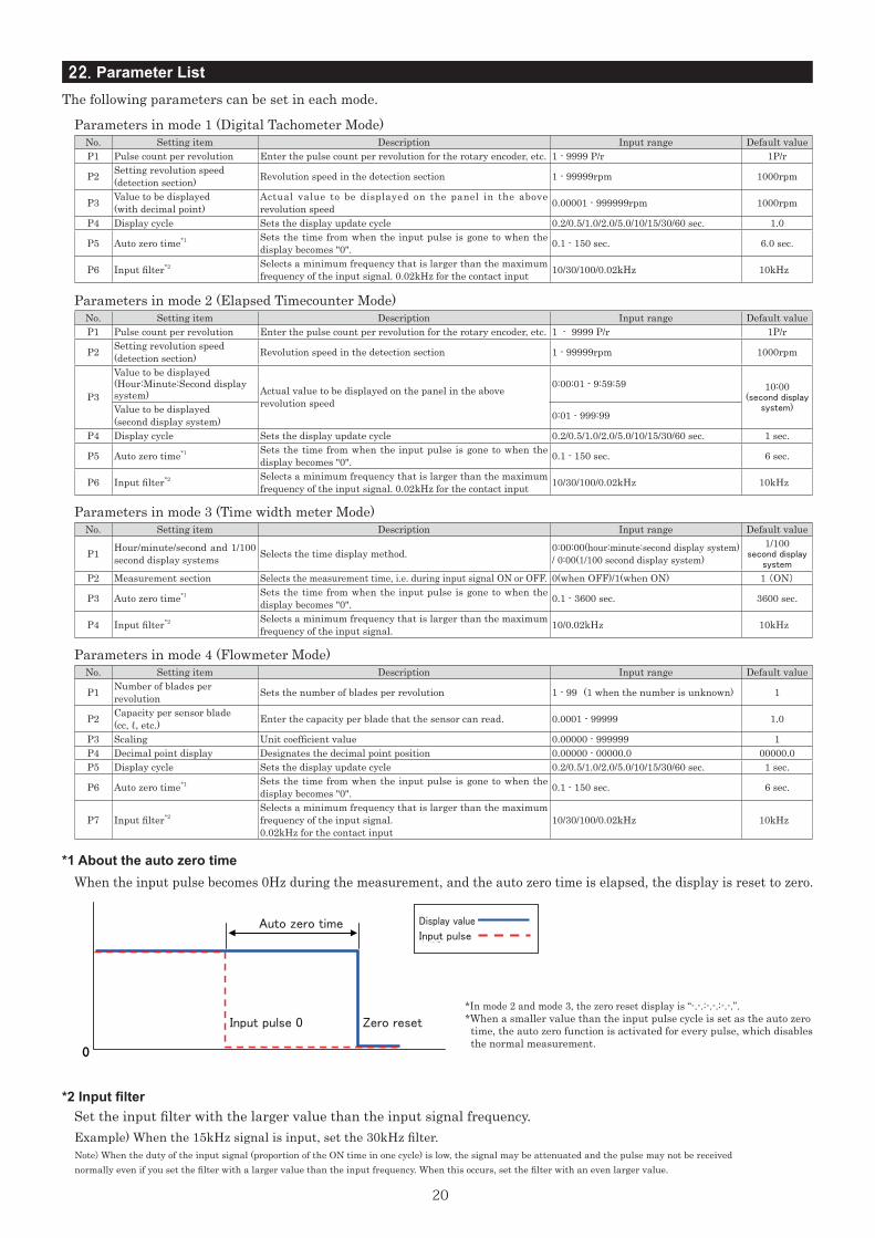
When the input pulse becomes 0Hz during the measurement, and the auto zero time is elapsed, the display is reset to zero.
Set the input filter with the larger value than the input signal frequency.
Note) When the duty of the input signal (proportion of the ON time in one cycle) is low, the signal may be attenuated and the pulse may not be received normally even if you set the filter with a larger value than the input frequency. When this occurs, set the filter with an even larger value.
Example) When the 15kHz signal is input, set the 30kHz filter.
*In mode 2 and mode 3, the zero reset display is “-.-.:-.-.:-.-.”.*When a smaller value than the input pulse cycle is set as the auto zero time, the auto zero function is activated for every pulse, which disables the normal measurement.
表示値
入力パルス
0
オートゼロ時間
ゼロリセット 入力パルス 0
22. Parameter ListThe following parameters can be set in each mode.
Auto zero time
Input pulse 0
Input pulse
Display value
Zero reset
21
Function in mode 1 (Digital Tachometer Mode)
Function setting item in mode 2 (Elapsed Timecounter Mode)
Function setting item in mode 3 (Time width meter Mode)
Function in mode 4 (Flowmeter Mode)
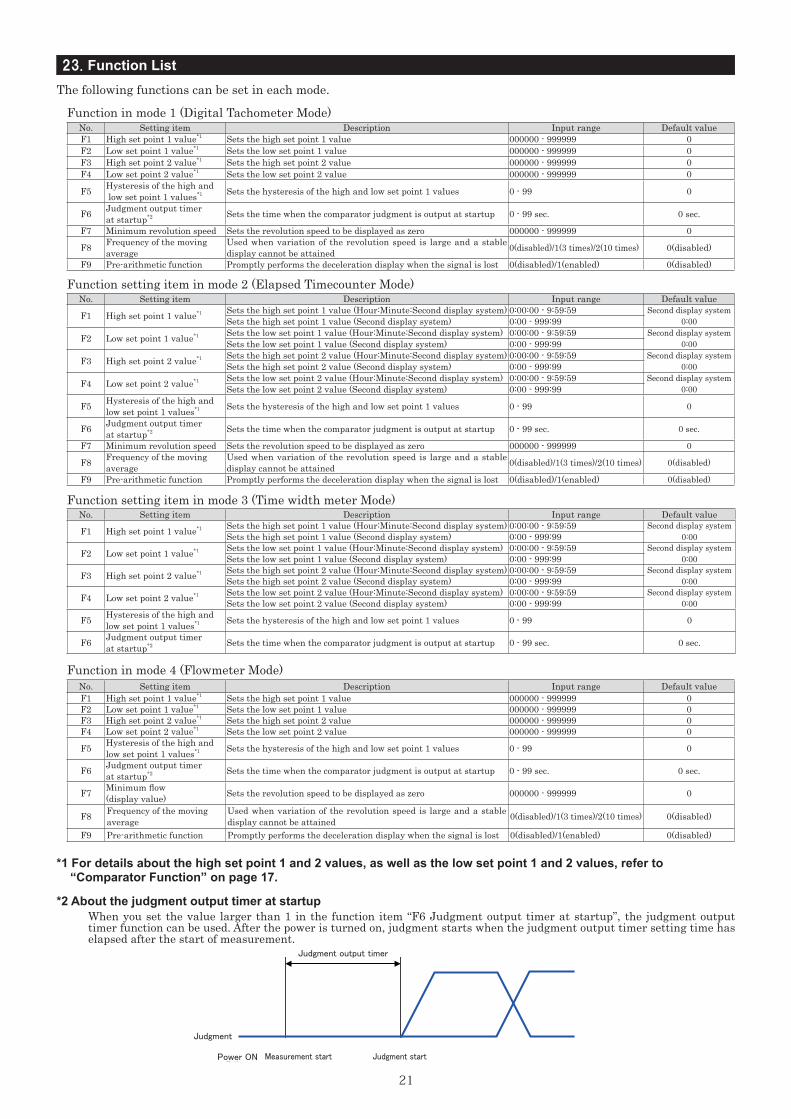
*2 About the judgment output timer at startupWhen you set the value larger than 1 in the function item “F6 Judgment output timer at startup”, the judgment output timer function can be used. After the power is turned on, judgment starts when the judgment output timer setting time has elapsed after the start of measurement.
*1 For details about the high set point 1 and 2 values, as well as the low set point 1 and 2 values, refer to “Comparator Function” on page 17.
No. Setting item Description Input range Default valueF1 High set point 1 value*1 Sets the high set point 1 value 000000 - 999999 0 F2 Low set point 1 value*1 Sets the low set point 1 value 000000 - 999999 0 F3 High set point 2 value*1 Sets the high set point 2 value 000000 - 999999 0 F4 Low set point 2 value*1 Sets the low set point 2 value 000000 - 999999 0
F5 Hysteresis of the high and low set point 1 values*1 Sets the hysteresis of the high and low set point 1 values 0 - 99 0
F6 Judgment output timerat startup*2 Sets the time when the comparator judgment is output at startup 0 - 99 sec. 0 sec.
F7 Minimum revolution speed Sets the revolution speed to be displayed as zero 000000 - 999999 0
F8 Frequency of the moving average
Used when variation of the revolution speed is large and a stable display cannot be attained 0(disabled)/1(3 times)/2(10 times) 0(disabled)
F9 Pre-arithmetic function Promptly performs the deceleration display when the signal is lost 0(disabled)/1(enabled) 0(disabled)
No. Setting item Description Input range Default value
F1 High set point 1 value*1 Sets the high set point 1 value (Hour:Minute:Second display system) 0:00:00 - 9:59:59 Second display system0:00Sets the high set point 1 value (Second display system) 0:00 - 999:99
F2 Low set point 1 value*1 Sets the low set point 1 value (Hour:Minute:Second display system) 0:00:00 - 9:59:59 Second display system0:00Sets the low set point 1 value (Second display system) 0:00 - 999:99
F3 High set point 2 value*1 Sets the high set point 2 value (Hour:Minute:Second display system) 0:00:00 - 9:59:59 Second display system0:00Sets the high set point 2 value (Second display system) 0:00 - 999:99
F4 Low set point 2 value*1 Sets the low set point 2 value (Hour:Minute:Second display system) 0:00:00 - 9:59:59 Second display system0:00Sets the low set point 2 value (Second display system) 0:00 - 999:99
F5 Hysteresis of the high andlow set point 1 values*1 Sets the hysteresis of the high and low set point 1 values 0 - 99 0
F6 Judgment output timerat startup*2 Sets the time when the comparator judgment is output at startup 0 - 99 sec. 0 sec.
F7 Minimum revolution speed Sets the revolution speed to be displayed as zero 000000 - 999999 0
F8 Frequency of the movingaverage
Used when variation of the revolution speed is large and a stable display cannot be attained 0(disabled)/1(3 times)/2(10 times) 0(disabled)
F9 Pre-arithmetic function Promptly performs the deceleration display when the signal is lost 0(disabled)/1(enabled) 0(disabled)
No. Setting item Description Input range Default value
F1 High set point 1 value*1 Sets the high set point 1 value (Hour:Minute:Second display system) 0:00:00 - 9:59:59 Second display system0:00Sets the high set point 1 value (Second display system) 0:00 - 999:99
F2 Low set point 1 value*1 Sets the low set point 1 value (Hour:Minute:Second display system) 0:00:00 - 9:59:59 Second display system0:00Sets the low set point 1 value (Second display system) 0:00 - 999:99
F3 High set point 2 value*1 Sets the high set point 2 value (Hour:Minute:Second display system) 0:00:00 - 9:59:59 Second display system0:00Sets the high set point 2 value (Second display system) 0:00 - 999:99
F4 Low set point 2 value*1 Sets the low set point 2 value (Hour:Minute:Second display system) 0:00:00 - 9:59:59 Second display system0:00Sets the low set point 2 value (Second display system) 0:00 - 999:99
F5 Hysteresis of the high andlow set point 1 values*1 Sets the hysteresis of the high and low set point 1 values 0 - 99 0
F6 Judgment output timer at startup*2 Sets the time when the comparator judgment is output at startup 0 - 99 sec. 0 sec.
No. Setting item Description Input range Default valueF1 High set point 1 value*1 Sets the high set point 1 value 000000 - 999999 0 F2 Low set point 1 value*1 Sets the low set point 1 value 000000 - 999999 0 F3 High set point 2 value*1 Sets the high set point 2 value 000000 - 999999 0 F4 Low set point 2 value*1 Sets the low set point 2 value 000000 - 999999 0
F5 Hysteresis of the high andlow set point 1 values*1 Sets the hysteresis of the high and low set point 1 values 0 - 99 0
F6 Judgment output timer at startup*2 Sets the time when the comparator judgment is output at startup 0 - 99 sec. 0 sec.
F7 Minimum flow (display value) Sets the revolution speed to be displayed as zero 000000 - 999999 0
F8 Frequency of the movingaverage
Used when variation of the revolution speed is large and a stable display cannot be attained 0(disabled)/1(3 times)/2(10 times) 0(disabled)
F9 Pre-arithmetic function Promptly performs the deceleration display when the signal is lost 0(disabled)/1(enabled) 0(disabled)
23. Function ListThe following functions can be set in each mode.
判定出力タイマ
判定開始 電源 ON
判定
計測開始
Judgment output timer
Power ON Judgment startMeasurement start
Judgment
22
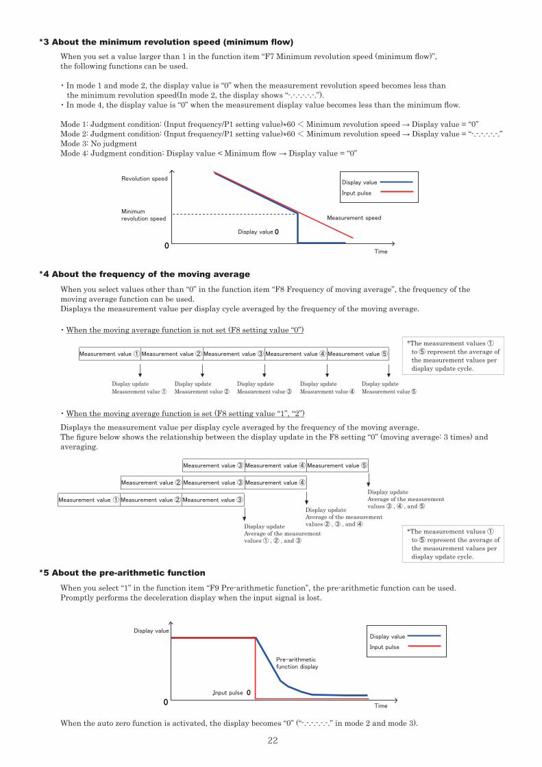
*3 About the minimum revolution speed (minimum flow)
*4 About the frequency of the moving average
*5 About the pre-arithmetic function
When you set a value larger than 1 in the function item “F7 Minimum revolution speed (minimum flow)”, the following functions can be used.
・ In mode 1 and mode 2, the display value is “0” when the measurement revolution speed becomes less than the minimum revolution speed(In mode 2, the display shows “-.-.-.-.-.-.”).
・ In mode 4, the display value is “0” when the measurement display value becomes less than the minimum flow.
Mode 1: Judgment condition: (Input frequency/P1 setting value)*60 < Minimum revolution speed → Display value = “0”Mode 2: Judgment condition: (Input frequency/P1 setting value)*60 < Minimum revolution speed → Display value = “-.-.-.-.-.-.”Mode 3: No judgmentMode 4: Judgment condition: Display value < Minimum flow → Display value = “0”
When you select values other than “0” in the function item “F8 Frequency of moving average”, the frequency of the moving average function can be used.Displays the measurement value per display cycle averaged by the frequency of the moving average.
When you select “1” in the function item “F9 Pre-arithmetic function”, the pre-arithmetic function can be used.Promptly performs the deceleration display when the input signal is lost.
・ When the moving average function is not set (F8 setting value “0”)
When the auto zero function is activated, the display becomes “0” (“-.-.-.-.-.-.” in mode 2 and mode 3).
Displays the measurement value per display cycle averaged by the frequency of the moving average.The figure below shows the relationship between the display update in the F8 setting “0” (moving average: 3 times) and averaging.
・ When the moving average function is set (F8 setting value “1”, “2”)
Display updateMeasurement value ①
Display updateMeasurement value ②
Display updateMeasurement value ③
Display updateMeasurement value ④
Display updateMeasurement value ⑤
*The measurement values ① to ⑤ represent the average of the measurement values per display update cycle.
*The measurement values ① to ⑤ represent the average of the measurement values per display update cycle.
Display updateAverage of the measurementvalues ① , ② , and ③
Display updateAverage of the measurementvalues ② , ③ , and ④
Display updateAverage of the measurementvalues ③ , ④ , and ⑤
Measurement value ① Measurement value ② Measurement value ③ Measurement value ④ Measurement value ⑤
Measurement value ① Measurement value ② Measurement value ③
Measurement value ② Measurement value ③ Measurement value ④
Measurement value ③ Measurement value ④ Measurement value ⑤
表示値
入力パルス
0
入力パルス 0
予測演算表示
表示値
入力パルス
0
計測速度
表示値 0
最小回転速度
Display value
Display valueDisplay value
Input pulse
Input pulse
Pre-arithmetic function display
Revolution speed
Minimum revolution speed
Display value
Measurement speed
Input pulse
Time
Time
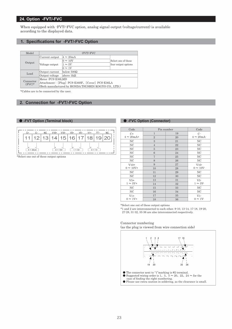
23
24. Option -FVT/-FVC
Model -FVT/-FVC
Output
Current output 4 ~ 20mASelect one of these four output optionsVoltage output
0 ~ 10V1 ~ 5V0 ~ 1V
Load Output current below 500ΩOutput voltage above 1kΩ
Connector(FVC)*
Meter :PCS-E36LMDAttachment : [Plug] PCS-E36SF、 [Cover] PCS-E36LA(Both manufactured by HONDA TSUSHIN KOGYO CO., LTD.)
When equipped with -FVT/-FVC option, analog signal output (voltage/current) is availableaccording to the displayed data.
*Cables are to be connected by the user.
1. Specifications for -FVT/-FVC Option
2. Connection for -FVT/-FVC Option
● -FVT Option (Terminal block) ● -FVC Option (Connector)
C+ C- NC NCV1-
4 ~ 20mA 0 ~ 10V 1 ~ 5V 0 ~ 1V+ + + +- - - -
V10+ V10- V5+ V5- V1+
*Select one out of these output options
11 12 13 14 15 16 17 18 19 20
Code Pin number CodeC+
4 ~ 20mA+1 19 C-
4 ~ 20mA-2 20NC 3 21 NCNC 4 22 NCNC 5 23 NCNC 6 24 NCNC 7 25 NCNC 8 26 NC
V10+0 ~ 10V+
9 27 V10-0 ~ 10V-10 28
NC 11 29 NCNC 12 30 NCV5+
1 ~ 5V+13 31 V5-
1 ~ 5V-14 32NC 15 33 NCNC 16 34 NCV1+
0 ~ 1V+17 35 V1-
0 ~ 1V-18 36
*1 and 2 are interconnected to each other. 9-10, 13-14, 17-18, 19-20, 27-28, 31-32, 35-36 are also interconnected respectively.
Connector numbering (as the plug is viewed from wire connection side)
● The connector next to “1”marking is #2 terminal.● Suggested wiring order is 1、 3、 5 ~ 20、 22、 24 ~ for the ease of finding the right numbering.● Please use extra caution in soldering, as the clearance is small.
⑲ ⑳ 35 36
1 2 3 4 17 18
19 20 35 36
*Select one out of these output options
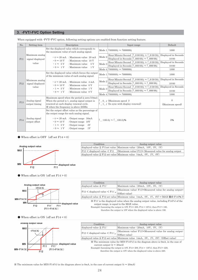
24
3. -FVT/-FVC Option Setting
Analog output value
displayed valueF12 F11
MAX
MIN
Analog output value
displayed value F12 F11´ F11
MAX
MIN
+F14(%)
(F11-F14(%))
F11 F11´
-F14(%) MAX
displayed value MIN
Analog output value
MIN-F14(%)
MIN+F14(%)
(F11+F14(%)) F12
Analog output value
displayed valueF12 F11
MAX
MIN
Analog output value
displayed value F12 F11´ F11
MAX
MIN
+F14(%)
(F11-F14(%))
F11 F11´
-F14(%) MAX
displayed value MIN
Analog output value
MIN-F14(%)
MIN+F14(%)
(F11+F14(%)) F12
Analog output value
displayed valueF12 F11
MAX
MIN
Analog output value
displayed value F12 F11´ F11
MAX
MIN
+F14(%)
(F11-F14(%))
F11 F11´
-F14(%) MAX
displayed value MIN
Analog output value
MIN-F14(%)
MIN+F14(%)
(F11+F14(%)) F12
When equipped with -FVT/-FVC option, following setting options are enabled from function setting feature.
No. Setting item Description Input range Default
F11Maximum analog signal displayed
value
Set the displayed value which corresponds to the maximum value of each analog signal. Mode 1 「000000」 ~ 「999999」 1000
・ 4 ~ 20 mA ・ 0 ~ 10 V ・ 1 ~ 5 V ・ 0 ~ 1 V
: Maximum value 20 mA: Maximum value 10 V: Maximum value 5 V: Maximum value 1 V
Mode 2Hour:Minute:Second 「_0:00:00」 ~ 「_9:59:59」 Displayed in Seconds
10:00Displayed in Seconds 「_000:00」 ~ 「_999:99」
Mode 3Hour:Minute:Second 「_0:00:00」 ~ 「_0:59:59」 Displayed in Seconds
10:00Displayed in Seconds 「_000:00」 ~ 「_999:99」
Mode 4 「000000」 ~ 「999999」 1000
F12Minimum analog signal displayed
value
Set the displayed value which forces the output of the minimum value of each analog signal. Mode 1 「000000」 ~ 「999999」 1000
・ 4 ~ 20 mA ・ 0 ~ 10 V ・ 1 ~ 5 V ・ 0 ~ 1 V
: Minimum value 4 mA: Minimum value 0 V: Minimum value 1 V: Minimum value 0 V
Mode 2Hour:Minute:Second 「_0:00:00」 ~ 「_9:59:59」 Displayed in Seconds
10:00Displayed in Seconds 「_000:00」 ~ 「_999:99」
Mode 3Hour:Minute:Second 「_0:00:00」 ~ 「_0:59:59」 Displayed in Seconds
10:00Displayed in Seconds 「_000:00」 ~ 「_999:99」
Mode 4 「000000」 ~ 「999999」 1000
F13 Analog signal output timing
Maximum speed when the period is zero.(10ms). When the period is 1, analog signal output is renewed at each display renewal cycle.※ when the frequency is above 200Hz
「 _ 0_ 」 (Maximum speed )/ 「 _ 1_ 」 (In sync with display renewal)
0(Maximum speed)
F14 Analog signal output offset
Set the output offset value as the percentage of the output range for each analog signal.
「__-100.0」 ~ 「__100.0」% 0% ・ 4 ~ 20 mA
・ 0 ~ 10 V ・ 1 ~ 5 V ・ 0 ~ 1 V
: Output range 16mA: Output range 10V: Output range 4V: Output range 1V
● When offset is OFF (off set F14 = 0)
● When offset is ON (off set F14 > 0)
● When offset is ON (off set F14 < 0)
Condition Analog output valuedisplayed value ≧ F11set value Maximum value (20mA、 10V、 5V、 1V)
F12 < displayed value < F11 (Maximum value/ F11)× Measured value for analog outputdisplayed value ≦ F12 set value Minimum value (4mA、 0V、 1V、 0V)
Condition Analog output valuedisplayed value ≧ F11´ Maximum value (20mA、 10V、 5V、 1V)
F12 < displayed value < F11´※
(Maximum value/ F11)×Measured value for analog output+ (Offset value)
displayed value ≦ F12 set value Minimum value (4mA、 0V、 1V、 0V) + (MAX 値の F14(% ))
Condition Analog output valuedisplayed value ≧ F11´ Maximum value (20mA、 10V、 5V、 1V)
F12 < displayed value < F11´※
(Maximum value/ F11)×Measured value for analog output- (Offset value)
displayed value ≦ F12 set value Minimum value (4mA、 0V、 1V、 0V) - (Offset value)
※ F11' is the displayed value when the analog output value, including F14(%) of the output range, is equal to the MAX value.Example) Assuming the output is 10V, F11= 200, F14 = 10(%), then F11'= 180, therefore the output is 10V when the displayed value is above 180.
※ The minimum value for MIN-F14(%) in the diagram above is 0mA, in the case of current output (4 ~ 20mA)Example) Assuming the output is 10V, F11= 200, F14 = -10(%), then F11'= 220, therefore the output is 10V when the displayed value is above 220.
※ The minimum value for MIN-F14(%) in the diagram above is 0mA, in the case of current output (4 ~ 20mA)
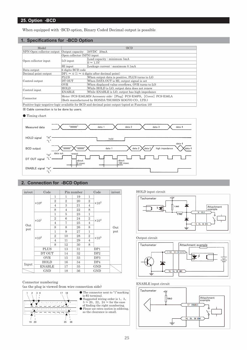
25
25. Option -BCD
When equipped with -BCD option, Binary Coded Decimal output is possible
● Timing chart
Measured data “00000” data 1 data 2 data 3 data 4
HOLD signal “H”“L”
BCD output
hold
“00000” “00000” data 1 data 2 data 3 high impedance
data 4
data 4
DT OUT signal“H”
“H”
“L”
“L”
data out renewal
ENABLE signal
about6 msec
about100 msec
Model -BCDNPN Open collector output Output capacity 30VDC 20mA
Open collector input
Open collector (NPN) input
LO input Load capacity : minimum 5mA0 ~ 1.5V
HI input Leakage current : maximum 0.1mAData output 6 digits BCD codeDecimal point output DP1 ~ 4 (1 ~ 4 digits after decimal point)
Control outputPLUS When output data is positive, PLUS turns to LODT OUT When DATA OUT is HI, output signal is setOVR When displayed value overflows, OVR turns to LO
Control input HOLD While HOLD is LO, output data does not renewENABLE While ENABLE is LO, output has high impedance
Connector Meter :PCS-E36LMD/ Accessory side: [Plug] PCS-E36FS、 [Cover] PCS-E36LA(Both manufactured by HONDA TSUSHIN KOGYO CO., LTD.)
Positive-logic-negative-logic available for BCD and decimal point output (opted at Function 10)※ Cable connection is to be done by users.
in/out Code Pin number Code in/out
Out put
×100
1 1 19 1
×103
Out put
2 2 20 24 3 21 48 4 22 8
×101
1 5 23 1
×1042 6 24 24 7 25 48 8 26 8
×102
1 9 27 1
×1052 10 28 24 11 29 48 12 30 8
PLUS 13 31 DP1DT OUT 14 32 DP2
OVR 15 33 DP3
Input HOLD 16 34 DP4ENABLE 17 35 GND
GND 18 36 GND
Connector numbering (as the plug is viewed from wire connection side)
1 2 3 4 17 18
19 20 35 36
1. Specifications for -BCD Option
2. Connection for -BCD Option
HOLD input circuit
Output circuit
ENABLE input circuit
Tachometer
Tachometer
Tachometer● The connector next to “1”marking is #2 terminal.● Suggested wiring order is 1、 3、 5 ~ 20、 22、 24 ~ for the ease of finding the right numbering.● Please use extra caution in soldering, as the clearance is small.
Attachment example
Attachment example
Attachment example
OUTPUT
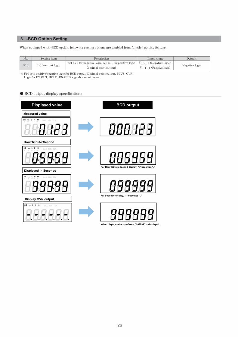
26
For Hour:Minute:Second display, ":" becomes "."
For Seconds display, ":" becomes "."
SIG LL L H HH MAX MIN TEA
SIG LL L H HH MAX MIN TEA
SIG LL L H HH MAX MIN TEA
Measured value
Hour:Minute:Second
Displayed in Seconds
SIG LL L H HH
Display OVR output
Displayed value BCD output
MAX MIN TEA
When display value overflows, "999999" is displayed.
3. -BCD Option Setting
When equipped with -BCD option, following setting options are enabled from function setting feature.
No. Setting item Description Input range Default
F10 BCD output logicSet as 0 for negative logic, set as 1 for positive logic
(decimal point output)「 _ 0_ 」 (Negative logic)/ 「 _ 1_ 」 (Positive logic)
Negative logic
※ F10 sets positive/negative logic for BCD output, Decimal point output, PLUS, OVR. Logic for DT OUT, HOLD, ENABLE signals cannot be set.
● BCD output display specifications
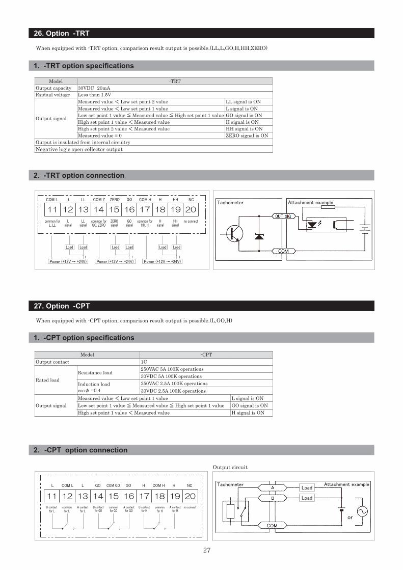
27
26. Option -TRT
27. Option -CPT
11 12 13 14 15 16 17 18 19 20
When equipped with -TRT option, comparison result output is possible.(LL,L,GO,H,HH,ZERO)
When equipped with -CPT option, comparison result output is possible.(L,GO,H)
1. -TRT option specifications
2. -TRT option connection
1. -CPT option specifications
2. -CPT option connection
Model -TRTOutput capacity 30VDC 20mARsidual voltage Less than 1.5V
Output signal
Measured value < Low set point 2 value LL signal is ONMeasured value < Low set point 1 value L signal is ONLow set point 1 value ≦ Measured value ≦ High set point 1 value GO signal is ONHigh set point 1 value < Measured value H signal is ONHigh set point 2 value < Measured value HH signal is ONMeasured value = 0 ZERO signal is ON
Output is insulated from internal circuitryNegative logic open collector output
Model -CPTOutput contact 1C
Rated loadResistance load
250VAC 5A 100K operations30VDC 5A 100K operations
Induction loadcosφ =0.4
250VAC 2.5A 100K operations30VDC 2.5A 100K operations
Output signalMeasured value < Low set point 1 value L signal is ONLow set point 1 value ≦ Measured value ≦ High set point 1 value GO signal is ONHigh set point 1 value < Measured value H signal is ON
Output circuit
COM L L HH NCCOM Z ZERO GO COM H H
common for L, LL
common for GO, ZERO
common for HH, H
LL
ZEROsignal
Lsignal
Hsignal
GOsignal
LLsignal
HHsignal
no connect
+ + +
Load Load LoadLoad Load
Load
Load
or
Load
11 12 13 14 15 16 17 18 19 20
- --
L COM L H NCGO COM GO GO H COM HL
B contact for L
commonfor L
commonfor H
A contactfor L
B contactfor GO
commonfor GO
A contactfor GO
B contactfor H
A contact for H
no connect
Power (+12V ~ +24V) Power (+12V ~ +24V) Power (+12V ~ +24V)
Attachment example
Tachometer
Tachometer
Attachment example
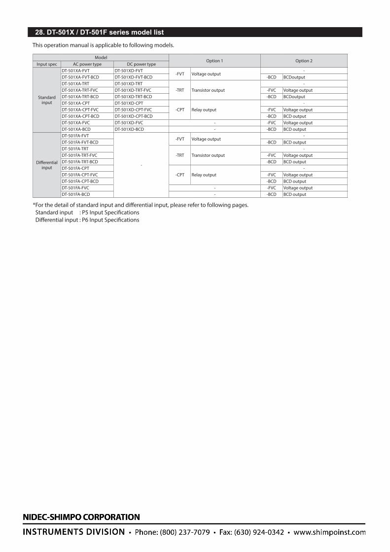
ModelOption 1 Option 2
Input spec AC power type DC power type
Standard input
DT-501XA-FVT DT-501XD-FVT-FVT Voltage output
-DT-501XA-FVT-BCD DT-501XD-FVT-BCD -BCD BCDoutputDT-501XA-TRT DT-501XD-TRT
-TRT Transistor output-
DT-501XA-TRT-FVC DT-501XD-TRT-FVC -FVC Voltage output DT-501XA-TRT-BCD DT-501XD-TRT-BCD -BCD BCDoutputDT-501XA-CPT DT-501XD-CPT
-CPT Relay output-
DT-501XA-CPT-FVC DT-501XD-CPT-FVC -FVC Voltage output DT-501XA-CPT-BCD DT-501XD-CPT-BCD -BCD BCD outputDT-501XA-FVC DT-501XD-FVC - -FVC Voltage output DT-501XA-BCD DT-501XD-BCD - -BCD BCD output
Differential input
DT-501FA-FVT
-
-FVT Voltage output -
DT-501FA-FVT-BCD -BCD BCD outputDT-501FA-TRT
-TRT Transistor output-
DT-501FA-TRT-FVC -FVC Voltage output DT-501FA-TRT-BCD -BCD BCD outputDT-501FA-CPT
-CPT Relay output-
DT-501FA-CPT-FVC -FVC Voltage output DT-501FA-CPT-BCD -BCD BCD outputDT-501FA-FVC - -FVC Voltage output DT-501FA-BCD - -BCD BCD output
This operation manual is applicable to following models.
*For the detail of standard input and differential input, please refer to following pages.Standard input : P5 Input SpecificationsDifferential input : P6 Input Specifications
28. DT-501X / DT-501F series model list