Embed Size (px)
Citation preview
1003-4
○
○
○
○
○
○
○
○
○
○
KSR Magnetic Float Switches
1003-4
2
KSR KUEBLER Niveau-Messtechnik AG
69439 ZwingenbergGermanyTel ++49 (0) 62 63 - 87- 0Fax ++49 (0) 62 63 - 87 99
KUBLER FRANCE S.A.68700 Cernay
KSR KUEBLER (UK)Level Measurement & Control Ltd.Molesey, Surrey KT8 1QZ
KSR KUEBLER (SCANDINAVIA)2970 Hørsholm
KSR KUEBLER (ITALY)Misura di Livello24030 Brembate S.(BG)
KSR KUEBLER (USA)Level Control Products of America Inc.Clarksville, VA 23927
KSR KUEBLER (SINGAPORE)Level Measurement & Control Pte. Ltd.Singapore 609916
SHANGHAI KSR KUEBLERAutomation Instruments Co. Ltd.Shanghai / China
1003-4
3
Contents
KSR Magnetic Float Switches
Description 4
Applications 5
Compass, Product range 6
Type code 7
KSR Magnetic Float Switches
Stainless steel SS 316 Ti 8
Stainless steel - adjustable 9
Stainless steel, II 1G EEx ia IIC T3-T6 10/11
Stainless steel, float Buna 12/13
Magnetic mini float switches 14/15
Food industry design 16
Sanitary design 17
Angular design 18/19
PVC, Polypropylene, or PVDF 20-23
Stainless steel, ECTFE-coated 24/25
Special flange design 26
Suspended float design 27
KSR Bypass Float Switches
Aluminium or Bronze 28
Stainless steel 29
Spherical floats 30
Cylindrical floats 31
Connection diagrams 32/33
Contact protection measures 34
Approvals
Technischer ÜberwachungsvereinSüdwestdeutschland e.V.Materials and type approval.Approved for pressure vessels acc. toAD-Merkblatt HP 0
IBExU Institut für SicherheitstechnikGmbH
Physikalisch TechnischeBundesanstalt PTB
Bundesamt für Wehrtechnikund Beschaffung
Germanischer Lloyd
Netherlands
KEMA
France
Laboratoire Central des IndustriesElectriques
Bureau Veritas
Norway
Det Norske Veritas
Czech Republic
Osvědčení o NevýbušnostiFTZÚ Ostrava Radvanice
Slovakia
Osvědčení o NevýbušnostiEVPÚ Nová Dubnica
Russia
GosgortechnadzorOGS Oil & Gas Safety
USA
Factory Mutual Research Corporation
Underwriters’ Laboratories, Inc.
Canada
Canadian Standards Association
1003-4
4
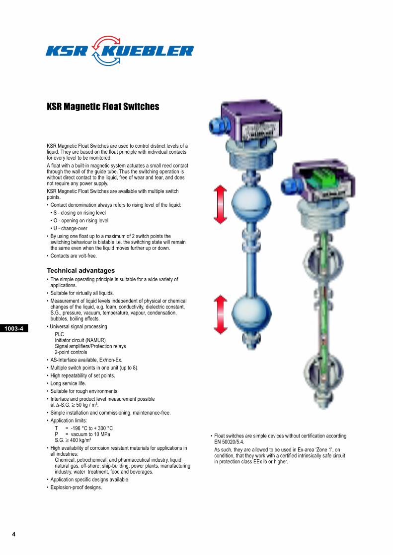
KSR Magnetic Float Switches
KSR Magnetic Float Switches are used to control distinct levels of aliquid. They are based on the float principle with individual contactsfor every level to be monitored.
A float with a built-in magnetic system actuates a small reed contactthrough the wall of the guide tube. Thus the switching operation iswithout direct contact to the liquid, free of wear and tear, and doesnot require any power supply.
KSR Magnetic Float Switches are available with multiple switchpoints.
• Contact denomination always refers to rising level of the liquid:
• S - closing on rising level
• O - opening on rising level
• U - change-over
• By using one float up to a maximum of 2 switch points theswitching behaviour is bistable i.e. the switching state will remainthe same even when the liquid moves further up or down.
• Contacts are volt-free.
Technical advantages• The simple operating principle is suitable for a wide variety of
applications.
• Suitable for virtually all liquids.
• Measurement of liquid levels independent of physical or chemicalchanges of the liquid, e.g. foam, conductivity, dielectric constant,S.G., pressure, vacuum, temperature, vapour, condensation,bubbles, boiling effects.
• Universal signal processing
PLCInitiator circuit (NAMUR)Signal amplifiers/Protection relays2-point controls
• AS-Interface available, Ex/non-Ex.
• Multiple switch points in one unit (up to 8).
• High repeatability of set points.
• Long service life.
• Suitable for rough environments.
• Interface and product level measurement possibleat ∆-S.G. ≥ 50 kg / m3.
• Simple installation and commissioning, maintenance-free.
• Application limits:
T = -196 °C to + 300 °CP = vacuum to 10 MPaS.G. ≥ 400 kg/m3
• High availability of corrosion resistant materials for applications inall industries:
Chemical, petrochemical, and pharmaceutical industry, liquidnatural gas, off-shore, ship-building, power plants, manufacturingindustry, water treatment, food and beverages.
• Application specific designs available.
• Explosion-proof designs.
• Float switches are simple devices without certification accordingEN 50020/5.4.
As such, they are allowed to be used in Ex-area ‘Zone 1’, oncondition, that they work with a certified intrinsically safe circuitin protection class EEx ib or higher.
1003-4
5
ϑ PT100
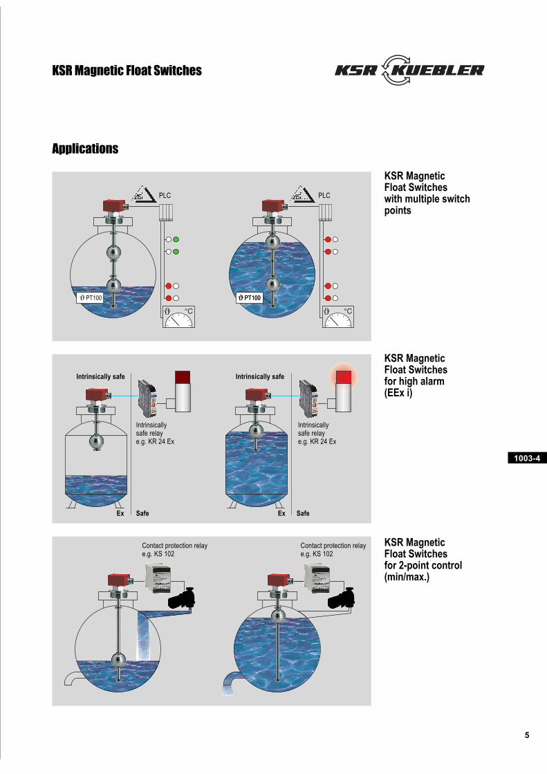
Applications
KSR MagneticFloat Switcheswith multiple switchpoints
KSR MagneticFloat Switchesfor high alarm(EEx i)
KSR MagneticFloat Switchesfor 2-point control(min/max.)
KSR Magnetic Float Switches
PLC PLC
ϑ PT100
Intrinsically safe Intrinsically safe
Ex ExSafe Safe
Intrinsicallysafe relaye.g. KR 24 Ex
Intrinsicallysafe relaye.g. KR 24 Ex
Contact protection relaye.g. KS 102
Contact protection relaye.g. KS 102
ϑ PT100
1003-4
6
KSR Magnetic Float Switches
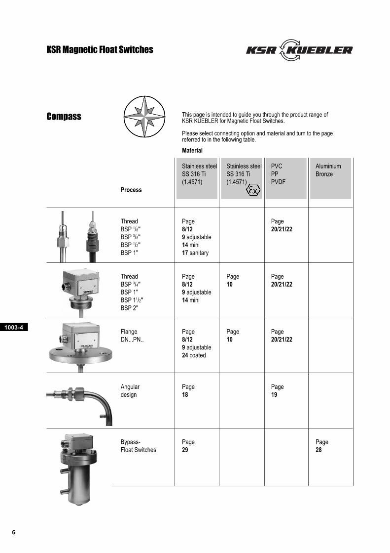
Compass This page is intended to guide you through the product range ofKSR KUEBLER for Magnetic Float Switches.
Please select connecting option and material and turn to the pagereferred to in the following table.
Material
Stainless steel Stainless steel PVC AluminiumSS 316 Ti SS 316 Ti PP Bronze(1.4571) (1.4571) PVDF
Process
Thread Page PageBSP 1/8" 8/12 20/21/22BSP 3/8" 9 adjustableBSP 1/2" 14 miniBSP 1" 17 sanitary
Thread Page Page PageBSP 3/4" 8/12 10 20/21/22BSP 1" 9 adjustableBSP 11/2" 14 miniBSP 2"
Flange Page Page PageDN...PN.. 8/12 10 20/21/22
9 adjustable24 coated
Angular Page Pagedesign 18 19
Bypass- Page PageFloat Switches 29 28
1003-4
7
KSR Magnetic Float Switches
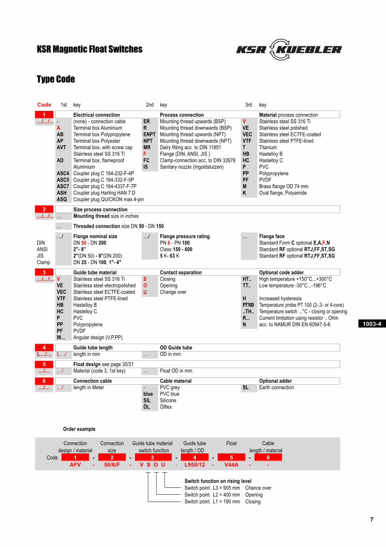
Code 1st key 2nd key 3rd key
1 Electrical connection Process connection Material process connection.../.../... - (none) - connection cable ER Mounting thread upwards (BSP) V Stainless steel SS 316 Ti
A Terminal box Aluminium R Mounting thread downwards (BSP) VE Stainless steel polishedAB Terminal box Polypropylene ENPT Mounting thread upwards (NPT) VEC Stainless steel ECTFE-coatedAP Terminal box Polyester NPT Mounting thread downwards (NPT) VTF Stainless steel PTFE-linedAVT Terminal box, with screw cap MR Dairy fitting acc. to DIN 11851 T Titanium
Stainless steel SS 316 Ti F Flange (DIN, ANSI, JIS ) HB Hastelloy BAD Terminal box, flameproof FC Clamp-connection acc. to DIN 32676 HC Hastelloy C
Aluminium IS Sanitary nozzle (Ingoldstutzen) P PVCASC4 Coupler plug C 164-232-F-4P PP PolypropyleneASC5 Coupler plug C 164-332-F-5P PF PVDFASC7 Coupler plug C 164-4337-F-7P M Brass flange OD 74 mmASH Coupler plug Harting HAN 7 D K Oval flange, PolyamideASQ Coupler plug QUICKON max.4-pin
2 Size process connection.../.../... ... Mounting thread size in inches
... Threaded connection size DN 50 - DN 150
.../ Flange nominal size .../ Flange pressure rating ... Flange faceDIN DN 50 - DN 200 PN 6 - PN 100 Standard Form C optional E,A,F,NANSI 2"- 8" Class 150 - 600 Standard RF optional RTJ,FF,ST,SGJIS 2"(DN 50) - 8"(DN 200) 5 K- 63 K Standard RF optional RTJ,FF,ST,SGClamp DN 25 - DN 100; 1"- 4"
3 Guide tube material Contact separation Optional code adder.../.../... V Stainless steel SS 316 Ti S Closing HT.. High temperature +150°C...+300°C
VE Stainless steel electropolished O Opening TT.. Low temperature -30°C...-196°CVEC Stainless steel ECTFE-coated U Change overVTF Stainless steel PTFE-lined H Increased hysteresisHB Hastelloy B PT100 Temperature probe PT 100 (2-,3- or 4-core)HC Hastelloy C ..TH.. Temperature switch ...°C - closing or openingP PVC R... Current limitation using resistor .. OhmPP Polypropylene N acc. to NAMUR DIN EN 60947-5-6PF PVDFW... Angular design (V,P,PP)
4 Guide tube length OD Guide tubeL.../... L.../ length in mm ... OD in mm
5 Float design see page 30/31.../... .../ Material (code 3, 1st key) ... Float OD in mm
6 Connection cable Cable material Optional adder.../... .../ length in Meter - PVC grey SL Earth connection
blue PVC blueSIL SiliconeÖL Ölflex
Order example
Connection Connection Guide tube material Guide tube Float Cabledesign / material size switch function length / OD length / material
Code 1 - 2 - 3 - 4 - 5 - 6AFV - 50/6/F - V S O U - L950/12 - V44A - -
Switch function on rising levelSwitch point L3 = 905 mm Chance overSwitch point L2 = 400 mm OpeningSwitch point L1 = 190 mm Closing
Type Code
1003-4
8
PG11
L=...
L1=.
..
L=...
L1=.
..
PG11
L=...
L1=.
..
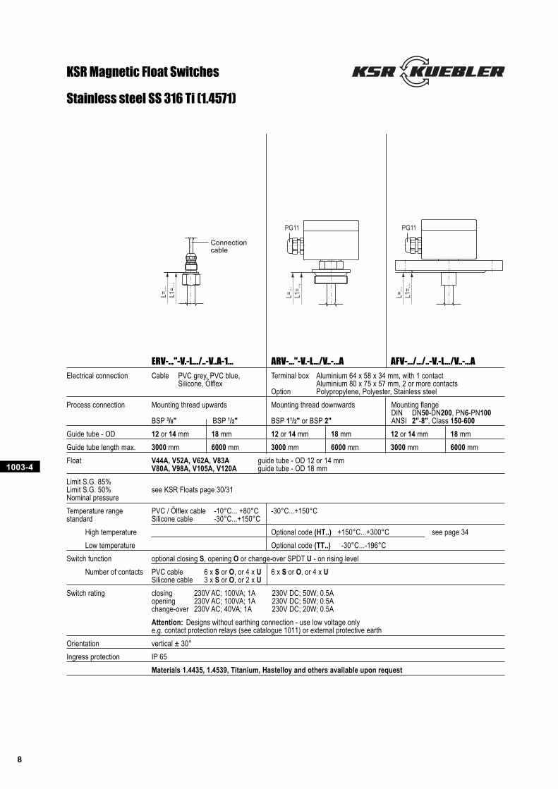
Stainless steel SS 316 Ti (1.4571)
KSR Magnetic Float Switches
ERV-..."-V.-L.../..-V..A-1... ARV-..."-V.-L.../V..-...A AFV-.../.../..-V.-L.../V..-...A
Electrical connection Cable PVC grey, PVC blue, Terminal box Aluminium 64 x 58 x 34 mm, with 1 contactSilicone, Ölflex Aluminium 80 x 75 x 57 mm, 2 or more contacts
Option Polypropylene, Polyester, Stainless steel
Process connection Mounting thread upwards Mounting thread downwards Mounting flangeDIN DN50-DN200, PN6-PN100
BSP 3/8" BSP 1/2" BSP 11/2" or BSP 2" ANSI 2"-8", Class 150-600
Guide tube - OD 12 or 14 mm 18 mm 12 or 14 mm 18 mm 12 or 14 mm 18 mm
Guide tube length max. 3000 mm 6000 mm 3000 mm 6000 mm 3000 mm 6000 mm
Float V44A, V52A, V62A, V83A guide tube - OD 12 or 14 mmV80A, V98A, V105A, V120A guide tube - OD 18 mm
Limit S.G. 85%Limit S.G. 50% see KSR Floats page 30/31Nominal pressure
Temperature range PVC / Ölflex cable -10°C... +80°C -30°C...+150°Cstandard Silicone cable -30°C...+150°C
High temperature Optional code (HT..) +150°C...+300°C see page 34
Low temperature Optional code (TT..) -30°C...-196°C
Switch function optional closing S, opening O or change-over SPDT U - on rising level
Number of contacts PVC cable 6 x S or O, or 4 x U 6 x S or O, or 4 x USilicone cable 3 x S or O, or 2 x U
Switch rating closing 230V AC; 100VA; 1A 230V DC; 50W; 0.5Aopening 230V AC; 100VA; 1A 230V DC; 50W; 0.5Achange-over 230V AC; 40VA; 1A 230V DC; 20W; 0.5A
Attention: Designs without earthing connection - use low voltage onlye.g. contact protection relays (see catalogue 1011) or external protective earth
Orientation vertical ± 30°
Ingress protection IP 65
Materials 1.4435, 1.4539, Titanium, Hastelloy and others available upon request
Connectioncable
1003-4
9
L=...
L1=.
..
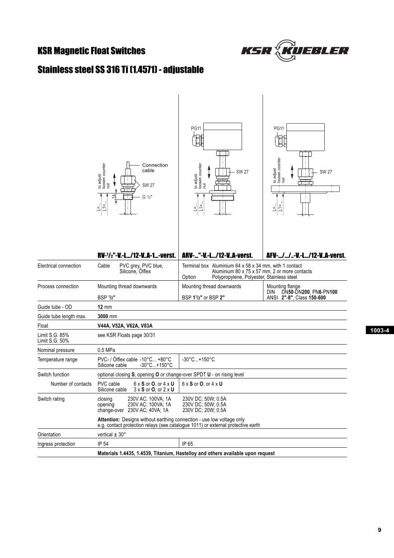
14 G 1/2"
SW 27
PG11
L=...
L1=.
..
SW 27
PG11
L=...
L1=.
..
SW 27
Stainless steel SS 316 Ti (1.4571) - adjustable
KSR Magnetic Float Switches
RV-1/2"-V.-L.../12-V..A-1...-verst. ARV-..."-V.-L.../12-V..A-verst. AFV-.../.../..-V.-L.../12-V..A-verst.
Electrical connection Cable PVC grey, PVC blue, Terminal box Aluminium 64 x 58 x 34 mm, with 1 contactSilicone, Ölflex Aluminium 80 x 75 x 57 mm, 2 or more contacts
Option Polypropylene, Polyester, Stainless steel
Process connection Mounting thread downwards Mounting thread downwards Mounting flangeDIN DN50-DN200, PN6-PN100
BSP 1/2" BSP 11/2" or BSP 2" ANSI 2"-8", Class 150-600
Guide tube - OD 12 mm
Guide tube length max. 3000 mm
Float V44A, V52A, V62A, V83A
Limit S.G. 85% see KSR Floats page 30/31Limit S.G. 50%
Nominal pressure 0.5 MPa
Temperature range PVC- / Ölflex cable -10°C... +80°C -30°C...+150°CSilicone cable -30°C...+150°C
Switch function optional closing S, opening O or change-over SPDT U - on rising level
Number of contacts PVC cable 6 x S or O, or 4 x U 6 x S or O, or 4 x USilicone cable 3 x S or O, or 2 x U
Switch rating closing 230V AC; 100VA; 1A 230V DC; 50W; 0.5Aopening 230V AC; 100VA; 1A 230V DC; 50W; 0.5Achange-over 230V AC; 40VA; 1A 230V DC; 20W; 0.5A
Attention: Designs without earthing connection - use low voltage onlye.g. contact protection relays (see catalogue 1011) or external protective earth
Orientation vertical ± 30°
Ingress protection IP 54 IP 65
Materials 1.4435, 1.4539, Titanium, Hastelloy and others available upon request
Connectioncable
to a
dju
st
loo
se
n c
ou
nte
rn
ut
to a
dju
st
loo
se
n c
ou
nte
rn
ut to
ad
just
loo
se
n c
ou
nte
rn
ut
1003-4
10
L=...
L1=.
..
PG11
X
PG11
L=...
L1=.
..X
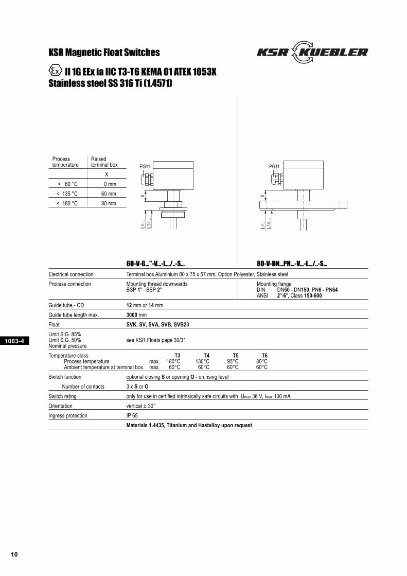
KSR Magnetic Float Switches
60-V-G..."-V...-L.../..-S... 80-V-DN...PN...-V...-L.../..-S...
Electrical connection Terminal box Aluminium 80 x 75 x 57 mm, Option Polyester, Stainless steel
Process connection Mounting thread downwards Mounting flangeBSP 1" - BSP 2" DIN DN50 - DN150, PN6 - PN64
ANSI 2"-6", Class 150-600
Guide tube - OD 12 mm or 14 mm
Guide tube length max. 3000 mm
Float SVK, SV, SVA, SVB, SVB23
Limit S.G. 85%Limit S.G. 50% see KSR Floats page 30/31Nominal pressure
Temperature class T3 T4 T5 T6Process temperature max. 180°C 130°C 95°C 80°CAmbient temperature at terminal box max. 60°C 60°C 60°C 60°C
Switch function optional closing S or opening O - on rising level
Number of contacts 3 x S or O
Switch rating only for use in certified intrinsically safe circuits with Umax 36 V, Imax 100 mA
Orientation vertical ± 30°
Ingress protection IP 65
Materials 1.4435, Titanium and Hastelloy upon request
II 1G EEx ia IIC T3-T6 KEMA 01 ATEX 1053XStainless steel SS 316 Ti (1.4571)
Process Raisedtemperature terminal box
X
< 60 °C 0 mm
< 135 °C 60 mm
< 180 °C 80 mm
1003-4
11
A
B
L=...
UL2
= ..
.L1
= ..
.
L=...
AB
L3 =
...
UL4
= ..
.
L2 =
...
L1 =
...
L=...
L1 =
...
A
B
U
L=...
AB
L2 =
...
UL3
= ..
.
L1 =
...
L=...
AB
L4 =
...
UL5
= ..
.
L3 =
...
L2 =
...
L1 =
...
L=...
L5 =
...
UL6
= ..
.
L4 =
...
L3 =
...
L2 =
...
L1 =
...
AB
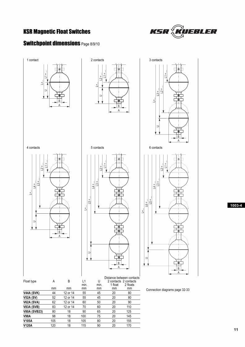
Distance between contactsFloat type A B L1 U 2 contacts 2 contacts
min. min. 1 float 2 floatsmm mm mm mm mm mm
V44A (SVK) 44 12 or 14 55 45 20 80V52A (SV) 52 12 or 14 55 45 20 80V62A (SVA) 62 12 or 14 60 50 20 90V83A (SVB) 83 12 or 14 70 60 20 110V80A (SVB23) 80 18 90 65 20 125V98A 98 18 100 75 20 145V105A 105 18 105 80 20 155V120A 120 18 115 90 20 170
Switchpoint dimensions Page 8/9/10
Connection diagrams page 32-33
1 contact 2 contacts 3 contacts
4 contacts 5 contacts 6 contacts
KSR Magnetic Float Switches
1003-4
12
L=...
L1=.
..
PG11PG11
L=...
L1=.
..
L=...
L1=.
..12 G 3/8"
SW 22
PG 7
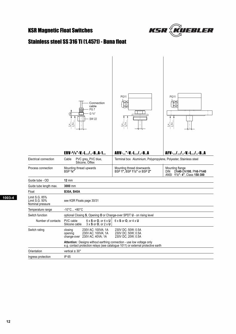
Stainless steel SS 316 Ti (1.4571) - Buna float
KSR Magnetic Float Switches
ERV-3/8"-V.-L .../..-B..A-1... ARV-..."-V.-L .../..-B..A AFV-.../.../..-V.-L .../..-B..A
Electrical connection Cable PVC grey, PVC blue, Terminal box Aluminium, Polypropylene, Polyester, Stainless steelSilicone, Ölflex
Process connection Mounting thread upwards Mounting thread downwards Mounting flangeBSP 3/8" BSP 1", BSP 11/2" or BSP 2" DIN DN40-DN100, PN6-PN40
ANSI 11/2"- 4", Class 150-300
Guide tube - OD 12 mm
Guide tube length max. 3000 mm
Float B30A, B40A
Limit S.G. 85%Limit S.G. 50% see KSR Floats page 30/31Nominal pressure
Temperature range -10°C... +80°C
Switch function optional Closing S, Opening O or Change-over SPDT U - on rising level
Number of contacts PVC cable 6 x S or O, or 4 x U 6 x S or O, or 4 x USilicone cable 3 x S or O, or 2 x U
Switch rating closing 230V AC; 100VA; 1A 230V DC; 50W; 0.5Aopening 230V AC; 100VA; 1A 230V DC; 50W; 0.5Achange-over 230V AC; 40VA; 1A 230V DC; 20W; 0.5A
Attention: Designs without earthing connection - use low voltage onlye.g. contact protection relays (see catalogue 1011) or external protective earth
Orientation vertical ± 30°
Ingress protection IP 65
Connectioncable
1003-4
13
L=...
L=...
A
B
AB
L=...
L1 =
...
U L2 =
...
UL3
= ..
.
L1 =
...
UL2
= ..
. L1 =
...
A
B
L=...
AB
L=...
AB
L=...
L3 =
...
UL4
= ..
.
L2 =
... L1
= ..
.
L4 =
...
UL5
= ..
.
L3 =
...
L2 =
... L1
= ..
.
L5 =
...
UL6
= ..
.
L4 =
... L3
= ..
.L2
= ..
. L1 =
...
AB
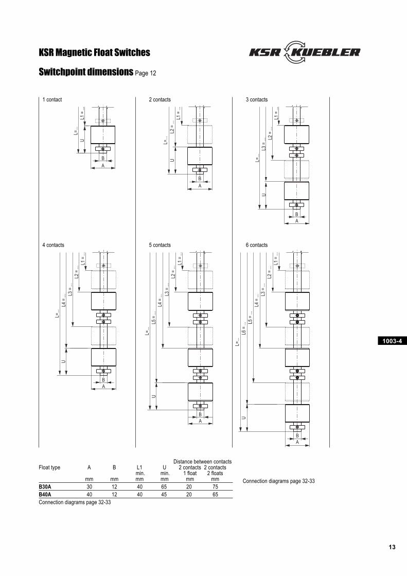
Distance between contactsFloat type A B L1 U 2 contacts 2 contacts
min. min. 1 float 2 floatsmm mm mm mm mm mm
B30A 30 12 40 65 20 75B40A 40 12 40 45 20 65Connection diagrams page 32-33
Switchpoint dimensions Page 12
1 contact 2 contacts 3 contacts
4 contacts 5 contacts 6 contacts
KSR Magnetic Float Switches
Connection diagrams page 32-33
1003-4
14
PG11
L=...
L1=.
..
L=...
L1=.
..8 G 1/8"
SW 14
L=...
L1=.
..
L=...
L1=.
..
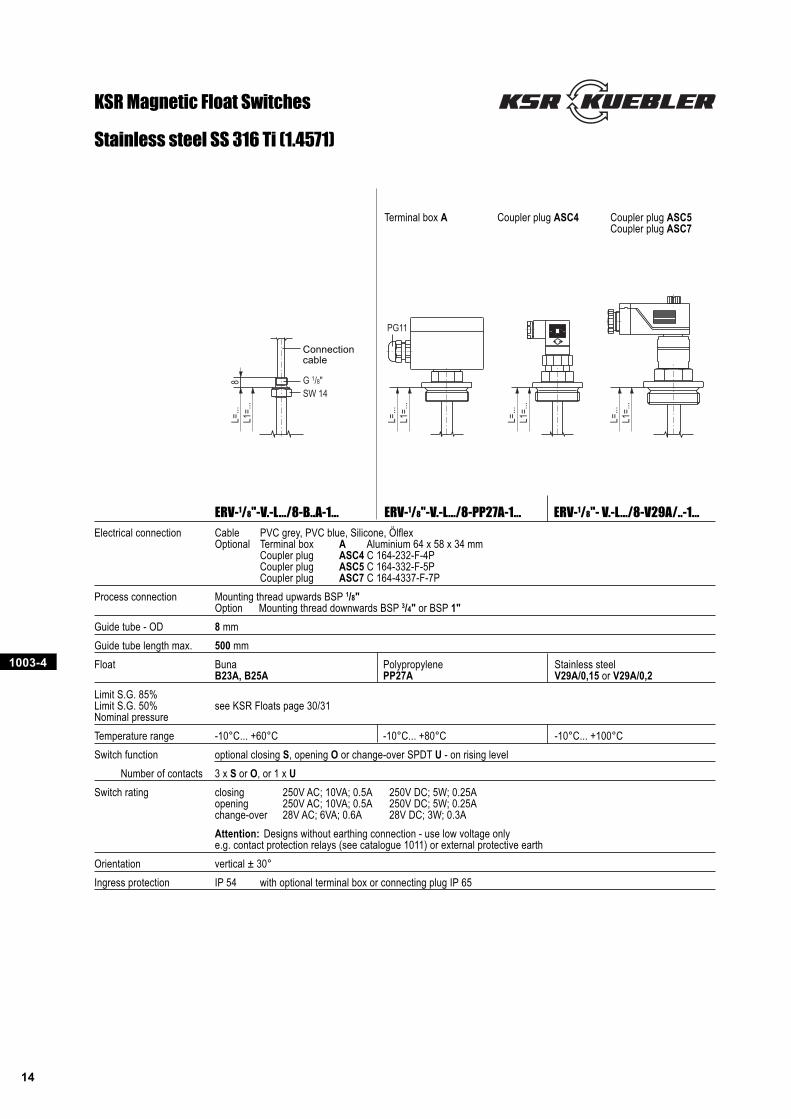
Stainless steel SS 316 Ti (1.4571)
KSR Magnetic Float Switches
ERV-1/8"-V.-L.../8-B..A-1... ERV-1/8"-V.-L.../8-PP27A-1... ERV-1/8"- V.-L.../8-V29A/..-1...
Electrical connection Cable PVC grey, PVC blue, Silicone, ÖlflexOptional Terminal box A Aluminium 64 x 58 x 34 mm
Coupler plug ASC4 C 164-232-F-4PCoupler plug ASC5 C 164-332-F-5PCoupler plug ASC7 C 164-4337-F-7P
Process connection Mounting thread upwards BSP 1/8"Option Mounting thread downwards BSP 3/4" or BSP 1"
Guide tube - OD 8 mm
Guide tube length max. 500 mm
Float Buna Polypropylene Stainless steelB23A, B25A PP27A V29A/0,15 or V29A/0,2
Limit S.G. 85%Limit S.G. 50% see KSR Floats page 30/31Nominal pressure
Temperature range -10°C... +60°C -10°C... +80°C -10°C... +100°C
Switch function optional closing S, opening O or change-over SPDT U - on rising level
Number of contacts 3 x S or O, or 1 x U
Switch rating closing 250V AC; 10VA; 0.5A 250V DC; 5W; 0.25Aopening 250V AC; 10VA; 0.5A 250V DC; 5W; 0.25Achange-over 28V AC; 6VA; 0.6A 28V DC; 3W; 0.3A
Attention: Designs without earthing connection - use low voltage onlye.g. contact protection relays (see catalogue 1011) or external protective earth
Orientation vertical ± 30°
Ingress protection IP 54 with optional terminal box or connecting plug IP 65
Terminal box A Coupler plug ASC4 Coupler plug ASC5Coupler plug ASC7
Connectioncable
1003-4
15
1 switchpoint
BUBNBK
L1
1 switchpoint
BUBN
L1
L=...
L1 =
...
U
AB
L=...
L1 =
...
U
AB
L=...
L1 =
...
U
AB
L=...
UL2
= ..
.L1
= ...
AB
L=...
UL2
= ..
.L1
= ..
.
AB
L=... L2
= ..
.L1
= ..
.U
AB
L=...
L2 =
...
UL3
= ..
.
L1 =
...
AB
L=...
L2 =
...
UL3
= ..
.
L1 =
...
AB
L=...
L2 =
...
UL3
= ..
.
L1 =
...
AB
2 switchpoints
BU
BKBN
L1
L2
3 switchpoints
BU
PK
GYBN
L1
L2
L3
3 switchpoints
BU
BK
GYBN
L1
L2
L3
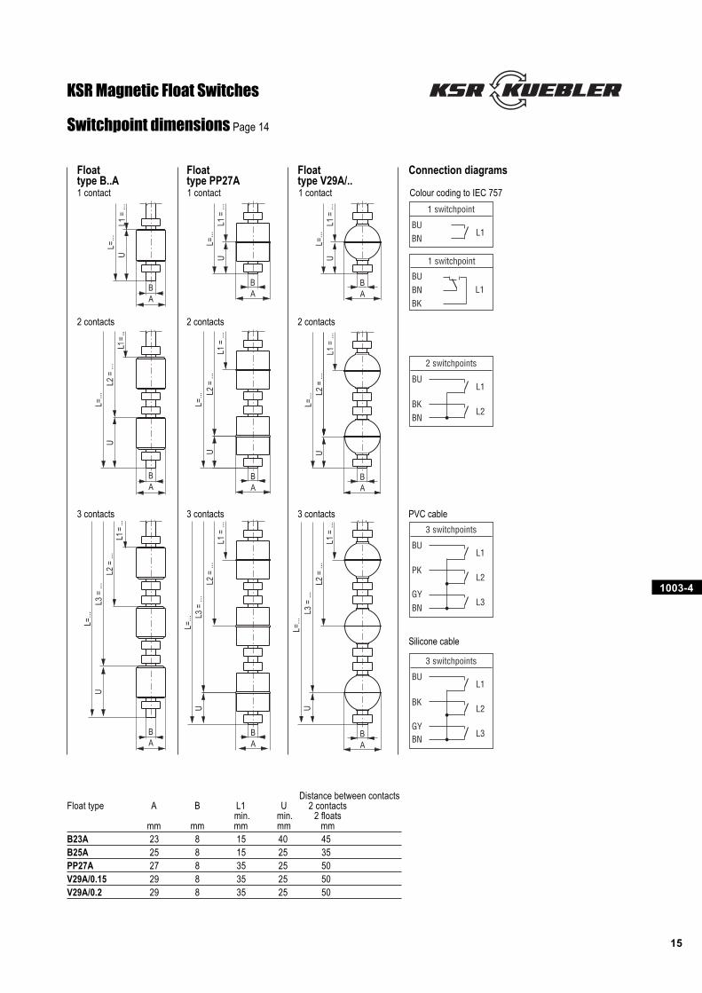
Distance between contactsFloat type A B L1 U 2 contacts
min. min. 2 floatsmm mm mm mm mm
B23A 23 8 15 40 45B25A 25 8 15 25 35PP27A 27 8 35 25 50V29A/0.15 29 8 35 25 50V29A/0.2 29 8 35 25 50
Switchpoint dimensions Page 14
Float Float Float Connection diagramstype B..A type PP27A type V29A/..1 contact 1 contact 1 contact Colour coding to IEC 757
2 contacts 2 contacts 2 contacts
3 contacts 3 contacts 3 contacts PVC cable
Silicone cable
KSR Magnetic Float Switches
1003-4
16
L=...
L1=.
..
PG11
U
BA
L=...
L1=.
..U
BA
PG11
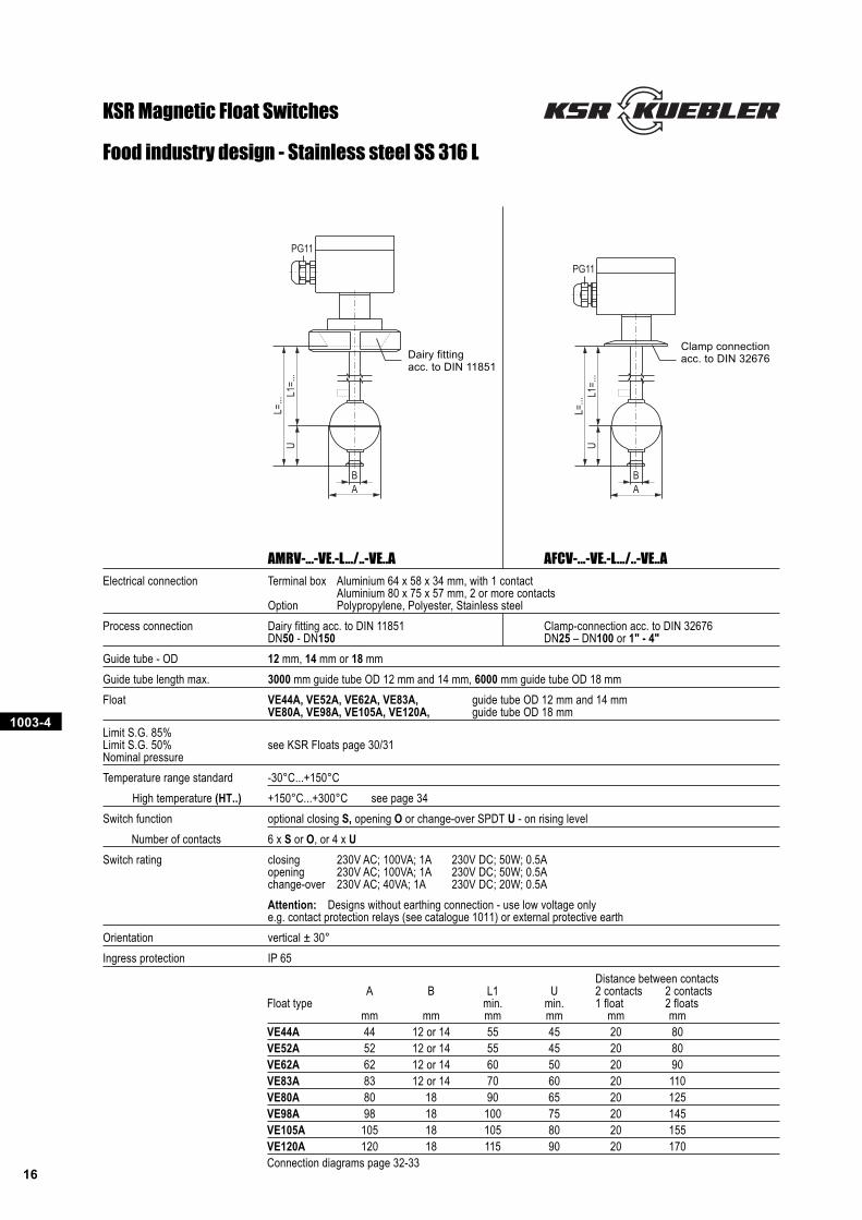
Food industry design - Stainless steel SS 316 L
KSR Magnetic Float Switches
AMRV-...-VE.-L.../..-VE..A AFCV-...-VE.-L.../..-VE..A
Electrical connection Terminal box Aluminium 64 x 58 x 34 mm, with 1 contactAluminium 80 x 75 x 57 mm, 2 or more contacts
Option Polypropylene, Polyester, Stainless steel
Process connection Dairy fitting acc. to DIN 11851 Clamp-connection acc. to DIN 32676DN50 - DN150 DN25 – DN100 or 1" - 4"
Guide tube - OD 12 mm, 14 mm or 18 mm
Guide tube length max. 3000 mm guide tube OD 12 mm and 14 mm, 6000 mm guide tube OD 18 mm
Float VE44A, VE52A, VE62A, VE83A, guide tube OD 12 mm and 14 mmVE80A, VE98A, VE105A, VE120A, guide tube OD 18 mm
Limit S.G. 85%Limit S.G. 50% see KSR Floats page 30/31Nominal pressure
Temperature range standard -30°C...+150°C
High temperature (HT..) +150°C...+300°C see page 34
Switch function optional closing S, opening O or change-over SPDT U - on rising level
Number of contacts 6 x S or O, or 4 x U
Switch rating closing 230V AC; 100VA; 1A 230V DC; 50W; 0.5Aopening 230V AC; 100VA; 1A 230V DC; 50W; 0.5Achange-over 230V AC; 40VA; 1A 230V DC; 20W; 0.5A
Attention: Designs without earthing connection - use low voltage onlye.g. contact protection relays (see catalogue 1011) or external protective earth
Orientation vertical ± 30°
Ingress protection IP 65
Distance between contactsA B L1 U 2 contacts 2 contacts
Float type min. min. 1 float 2 floatsmm mm mm mm mm mm
VE44A 44 12 or 14 55 45 20 80VE52A 52 12 or 14 55 45 20 80VE62A 62 12 or 14 60 50 20 90VE83A 83 12 or 14 70 60 20 110VE80A 80 18 90 65 20 125VE98A 98 18 100 75 20 145VE105A 105 18 105 80 20 155VE120A 120 18 115 90 20 170Connection diagrams page 32-33
Dairy fittingacc. to DIN 11851
Clamp connectionacc. to DIN 32676
1003-4
17
L=...
L1=.
..U
BA
L=...
L1=.
..
U
BA
L2=.
..
G 3/8"SW 15
L=...
L2=.
..
U
BA
L3=.
..
L1=.
..
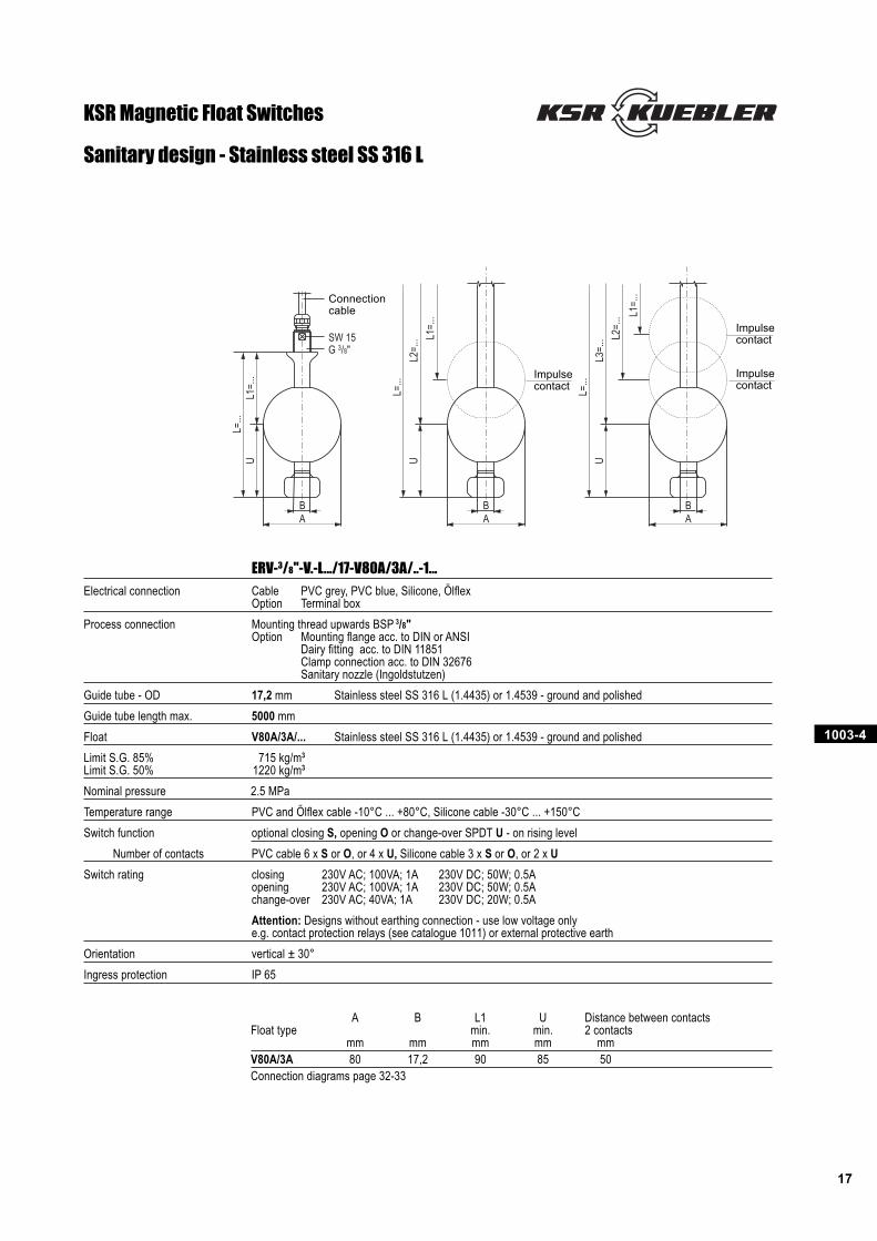
ERV-3/8"-V.-L.../17-V80A/3A/..-1...
Electrical connection Cable PVC grey, PVC blue, Silicone, ÖlflexOption Terminal box
Process connection Mounting thread upwards BSP 3/8"Option Mounting flange acc. to DIN or ANSI
Dairy fitting acc. to DIN 11851Clamp connection acc. to DIN 32676Sanitary nozzle (Ingoldstutzen)
Guide tube - OD 17,2 mm Stainless steel SS 316 L (1.4435) or 1.4539 - ground and polished
Guide tube length max. 5000 mm
Float V80A/3A/... Stainless steel SS 316 L (1.4435) or 1.4539 - ground and polished
Limit S.G. 85% 715 kg/m3
Limit S.G. 50% 1220 kg/m3
Nominal pressure 2.5 MPa
Temperature range PVC and Ölflex cable -10°C ... +80°C, Silicone cable -30°C ... +150°C
Switch function optional closing S, opening O or change-over SPDT U - on rising level
Number of contacts PVC cable 6 x S or O, or 4 x U, Silicone cable 3 x S or O, or 2 x U
Switch rating closing 230V AC; 100VA; 1A 230V DC; 50W; 0.5Aopening 230V AC; 100VA; 1A 230V DC; 50W; 0.5Achange-over 230V AC; 40VA; 1A 230V DC; 20W; 0.5A
Attention: Designs without earthing connection - use low voltage onlye.g. contact protection relays (see catalogue 1011) or external protective earth
Orientation vertical ± 30°
Ingress protection IP 65
A B L1 U Distance between contactsFloat type min. min. 2 contacts
mm mm mm mm mmV80A/3A 80 17,2 90 85 50Connection diagrams page 32-33
Sanitary design - Stainless steel SS 316 L
KSR Magnetic Float Switches
Connectioncable
Impulsecontact
Impulsecontact
Impulsecontact
1003-4
18
L=...
L1=.
..U
BA
W=…
G 3/8" SW 22
PG11 PG11
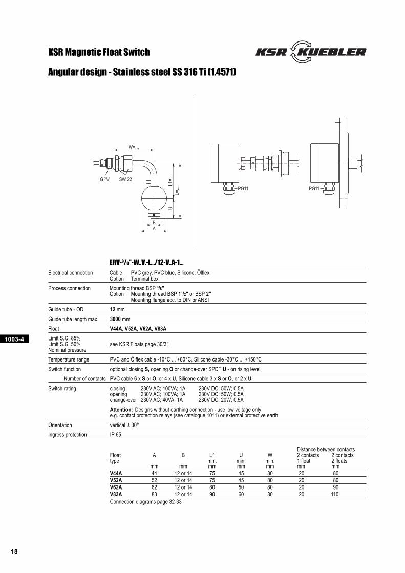
ERV-3/8"-W..V.-L.../12-V..A-1...
Electrical connection Cable PVC grey, PVC blue, Silicone, ÖlflexOption Terminal box
Process connection Mounting thread BSP 3/8"Option Mounting thread BSP 11/2" or BSP 2"
Mounting flange acc. to DIN or ANSI
Guide tube - OD 12 mm
Guide tube length max. 3000 mm
Float V44A, V52A, V62A, V83A
Limit S.G. 85%Limit S.G. 50% see KSR Floats page 30/31Nominal pressure
Temperature range PVC and Ölflex cable -10°C ... +80°C, Silicone cable -30°C ... +150°C
Switch function optional closing S, opening O or change-over SPDT U - on rising level
Number of contacts PVC cable 6 x S or O, or 4 x U, Silicone cable 3 x S or O, or 2 x U
Switch rating closing 230V AC; 100VA; 1A 230V DC: 50W; 0.5Aopening 230V AC; 100VA; 1A 230V DC: 50W; 0.5Achange-over 230V AC; 40VA; 1A 230V DC: 20W; 0.5A
Attention: Designs without earthing connection - use low voltage onlye.g. contact protection relays (see catalogue 1011) or external protective earth
Orientation vertical ± 30°
Ingress protection IP 65
Distance between contactsFloat A B L1 U W 2 contacts 2 contactstype min. min. min. 1 float 2 floats
mm mm mm mm mm mm mmV44A 44 12 or 14 75 45 80 20 80V52A 52 12 or 14 75 45 80 20 80V62A 62 12 or 14 80 50 80 20 90V83A 83 12 or 14 90 60 80 20 110Connection diagrams page 32-33
Angular design - Stainless steel SS 316 Ti (1.4571)
KSR Magnetic Float Switch
1003-4
19
L=...
L1=.
..U
W=…
BA
G 3/8" SW 22 SW 22
L=...
L1=.
..U
BA
W=…
G 3/8" SW 22
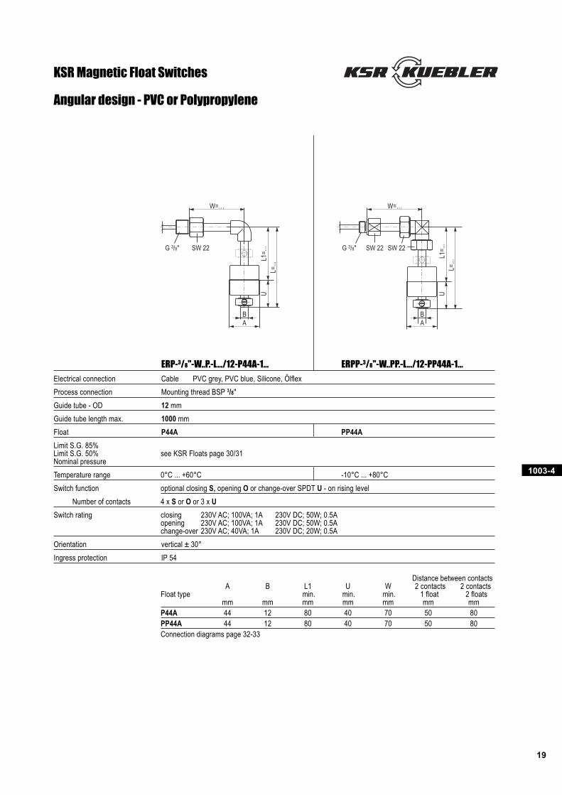
ERP-3/8"-W..P.-L.../12-P44A-1... ERPP-3/8"-W..PP.-L.../12-PP44A-1...
Electrical connection Cable PVC grey, PVC blue, Silicone, Ölflex
Process connection Mounting thread BSP 3/8"
Guide tube - OD 12 mm
Guide tube length max. 1000 mm
Float P44A PP44A
Limit S.G. 85%Limit S.G. 50% see KSR Floats page 30/31Nominal pressure
Temperature range 0°C ... +60°C -10°C ... +80°C
Switch function optional closing S, opening O or change-over SPDT U - on rising level
Number of contacts 4 x S or O or 3 x U
Switch rating closing 230V AC; 100VA; 1A 230V DC; 50W; 0.5Aopening 230V AC; 100VA; 1A 230V DC; 50W; 0.5Achange-over 230V AC; 40VA; 1A 230V DC; 20W; 0.5A
Orientation vertical ± 30°
Ingress protection IP 54
Distance between contactsA B L1 U W 2 contacts 2 contacts
Float type min. min. min. 1 float 2 floatsmm mm mm mm mm mm mm
P44A 44 12 80 40 70 50 80PP44A 44 12 80 40 70 50 80Connection diagrams page 32-33
Angular design - PVC or Polypropylene
KSR Magnetic Float Switches
1003-4
20
L=...
L1=.
..12 G 3/8"
SW 22
L=...
L1=.
..
PG11
L=...
L1=.
..
PG11
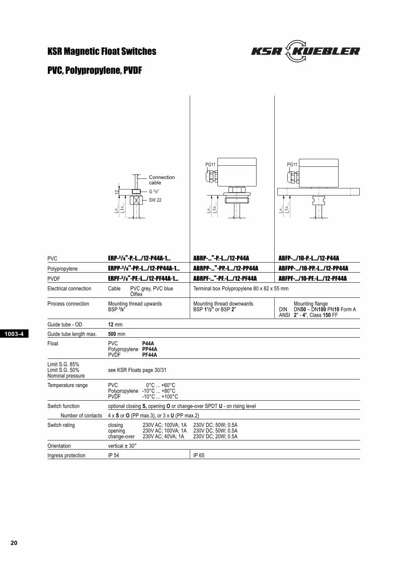
PVC, Polypropylene, PVDF
PVC ERP-3/8"-P.-L.../12-P44A-1... ABRP-..."-P.-L.../12-P44A ABFP-.../10-P.-L.../12-P44A
Polypropylene ERPP-3/8"-PP.-L.../12-PP44A-1... ABRPP-..."-PP.-L.../12-PP44A ABFPP-.../10-PP.-L.../12-PP44A
PVDF ERPF-3/8"-PF.-L.../12-PF44A-1... ABRPF-..."-PF.-L.../12-PF44A ABFPF-.../10-PF.-L.../12-PF44A
Electrical connection Cable PVC grey, PVC blue Terminal box Polypropylene 80 x 82 x 55 mmÖlflex
Process connection Mounting thread upwards Mounting thread downwards Mounting flangeBSP 3/8" BSP 11/2" or BSP 2" DIN DN50 – DN100 PN10 Form A
ANSI 2" - 4", Class 150 FF
Guide tube - OD 12 mm
Guide tube length max. 500 mm
Float PVC P44APolypropylene PP44APVDF PF44A
Limit S.G. 85%Limit S.G. 50% see KSR Floats page 30/31Nominal pressure
Temperature range PVC 0°C ... +60°CPolypropylene -10°C ... +80°CPVDF -10°C ... +100°C
Switch function optional closing S, opening O or change-over SPDT U - on rising level
Number of contacts 4 x S or O (PP max.3), or 3 x U (PP max.2)
Switch rating closing 230V AC; 100VA; 1A 230V DC; 50W; 0.5Aopening 230V AC; 100VA; 1A 230V DC; 50W; 0.5Achange-over 230V AC; 40VA; 1A 230V DC; 20W; 0.5A
Orientation vertical ± 30°
Ingress protection IP 54 IP 65
KSR Magnetic Float Switches
Connectioncable
1003-4
21
L=...
L1=.
..14 G 1/2"
SW 27
PG 9
L=...
L1=.
..
PG11
L=...
L1=.
..
PG11
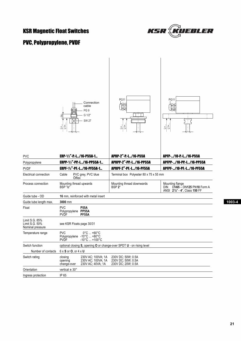
PVC, Polypropylene, PVDF
PVC ERP-1/2"-P.-L.../16-P55A-1... APRP-2"-P.-L.../16-P55A APFP-.../10-P.-L.../16-P55A
Polypropylene ERPP-1/2"-PP.-L.../16-PP55A-1... APRPP-2"-PP.-L.../16-PP55A APFPP-.../10-PP.-L.../16-PP55A
PVDF ERPF-1/2"-PF.-L.../16-PF55A-1... APRPF-2"-PF.-L.../16-PF55A APFPF-.../10-PF.-L.../16-PF55A
Electrical connection Cable PVC grey, PVC blue Terminal box Polyester 80 x 75 x 55 mmÖlflex
Process connection Mounting thread upwards Mounting thread downwards Mounting flangeBSP 1/2" BSP 2" DIN DN65 – DN125 PN10 Form A
ANSI 21/2" - 4", Class 150 FF
Guide tube - OD 16 mm, reinforced with metal insert
Guide tube length max. 3000 mm
Float PVC P55APolypropylene PP55APVDF PF55A
Limit S.G. 85%Limit S.G. 50% see KSR Floats page 30/31Nominal pressure
Temperature range PVC 0°C ... +60°CPolypropylene -10°C ... +80°CPVDF -10°C ... +100°C
Switch function optional closing S, opening O or change-over SPDT U - on rising level
Number of contacts 6 x S or O, or 4 x U
Switch rating closing 230V AC; 100VA; 1A 230V DC; 50W; 0.5Aopening 230V AC; 100VA; 1A 230V DC; 50W; 0.5Achange-over 230V AC; 40VA; 1A 230V DC; 20W; 0.5A
Orientation vertical ± 30°
Ingress protection IP 65
KSR Magnetic Float Switches
Connectioncable
1003-4
22
L=...
L1=.
..24 G 1”
SW 32
PG 9
L=...
L1=.
..
PG11
L=...
L1=.
..
PG11
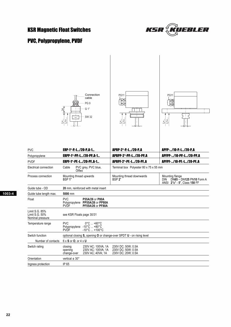
PVC, Polypropylene, PVDF
PVC ERP-1"-P.-L.../20-P..A-1... APRP-2"-P.-L.../20-P..A APFP-.../10-P.-L.../20-P..A
Polypropylene ERPP-1"-PP.-L.../20-PP..A-1... APRPP-2"-PP.-L.../20-PP..A APFPP-.../10-PP.-L.../20-PP..A
PVDF ERPF-1"-PF.-L.../20-PF..A-1... APRPF-2"-PF.-L.../20-PF..A APFPF-.../10-PF.-L.../20-PF..A
Electrical connection Cable PVC grey, PVC blue, Terminal box Polyester 80 x 75 x 55 mmÖlflex
Process connection Mounting thread upwards Mounting thread downwards Mounting flangeBSP 1" BSP 2" DIN DN65 – DN125 PN10 Form A
ANSI 21/2" - 5", Class 150 FF
Guide tube - OD 20 mm, reinforced with metal insert
Guide tube length max. 5000 mm
Float PVC P55A/26 or P80APolypropylene PP55A/26 or PP80APVDF PF55A/26 or PF80A
Limit S.G. 85%Limit S.G. 50% see KSR Floats page 30/31Nominal pressure
Temperature range PVC 0°C ... +60°CPolypropylene -10°C ... +80°CPVDF -10°C ... +100°C
Switch function optional closing S, opening O or change-over SPDT U - on rising level
Number of contacts 6 x S or O, or 4 x U
Switch rating closing 230V AC; 100VA; 1A 230V DC; 50W; 0.5Aopening 230V AC; 100VA; 1A 230V DC; 50W; 0.5Achange-over 230V AC; 40VA; 1A 230V DC; 20W; 0.5A
Orientation vertical ± 30°
Ingress protection IP 65
KSR Magnetic Float Switches
Connectioncable
1003-4
23
L=...
L=...
A
B
AB
L=...
L1 =
...
A
B
U
L2 =
...
UL3
= ..
.
L1 =
...
UL2
= ..
.L1
= ..
.
L=...
AB
L=...
AB
L=...
L3 =
...
UL4
= ..
.
L2 =
...
L1 =
...
L4 =
...
UL5
= ..
.
L3 =
...
L2 =
...
L1 =
...
L5 =
...
UL6
= ..
.
L4 =
...
L3 =
...
L2 =
...
L1 =
...
AB
Distance between contactsFloat type A B L1 U 2 contacts 2 contacts
min. min. 1 float 2 floatsmm mm mm mm mm mm
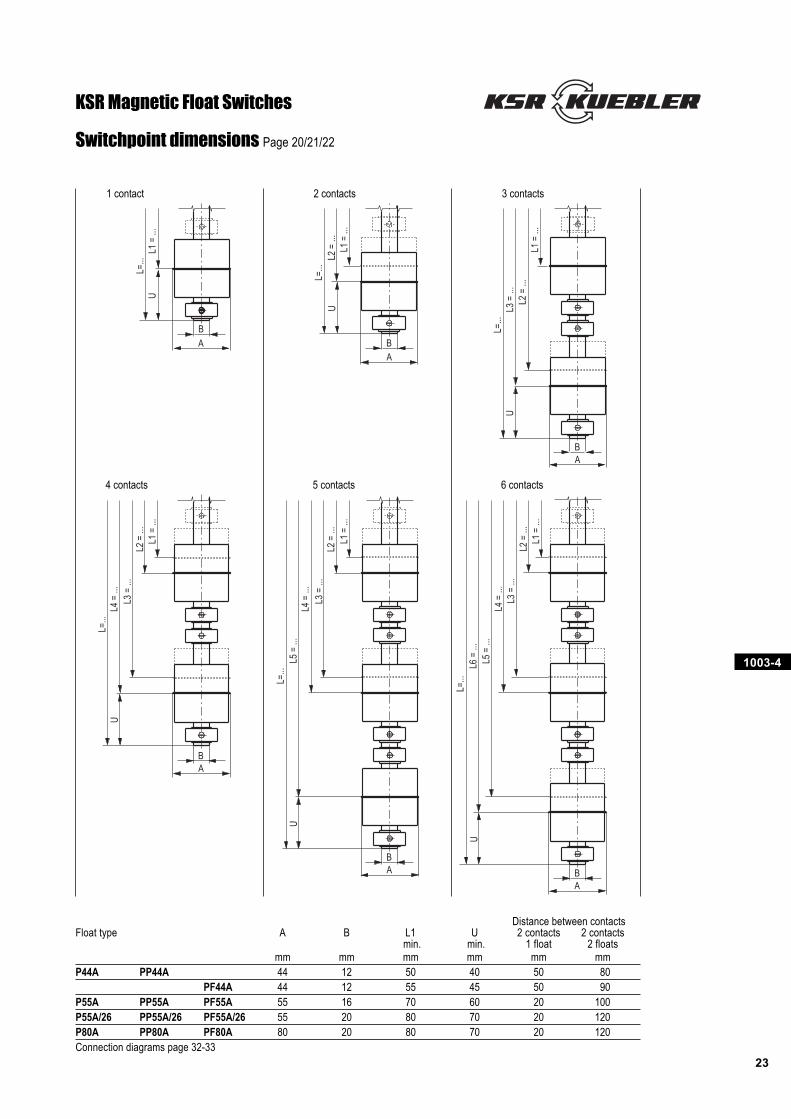
P44A PP44A 44 12 50 40 50 80PF44A 44 12 55 45 50 90
P55A PP55A PF55A 55 16 70 60 20 100P55A/26 PP55A/26 PF55A/26 55 20 80 70 20 120P80A PP80A PF80A 80 20 80 70 20 120Connection diagrams page 32-33
Switchpoint dimensions Page 20/21/22
1 contact 2 contacts 3 contacts
4 contacts 5 contacts 6 contacts
KSR Magnetic Float Switches
1003-4
24
L=...
L1=.
..
PG11
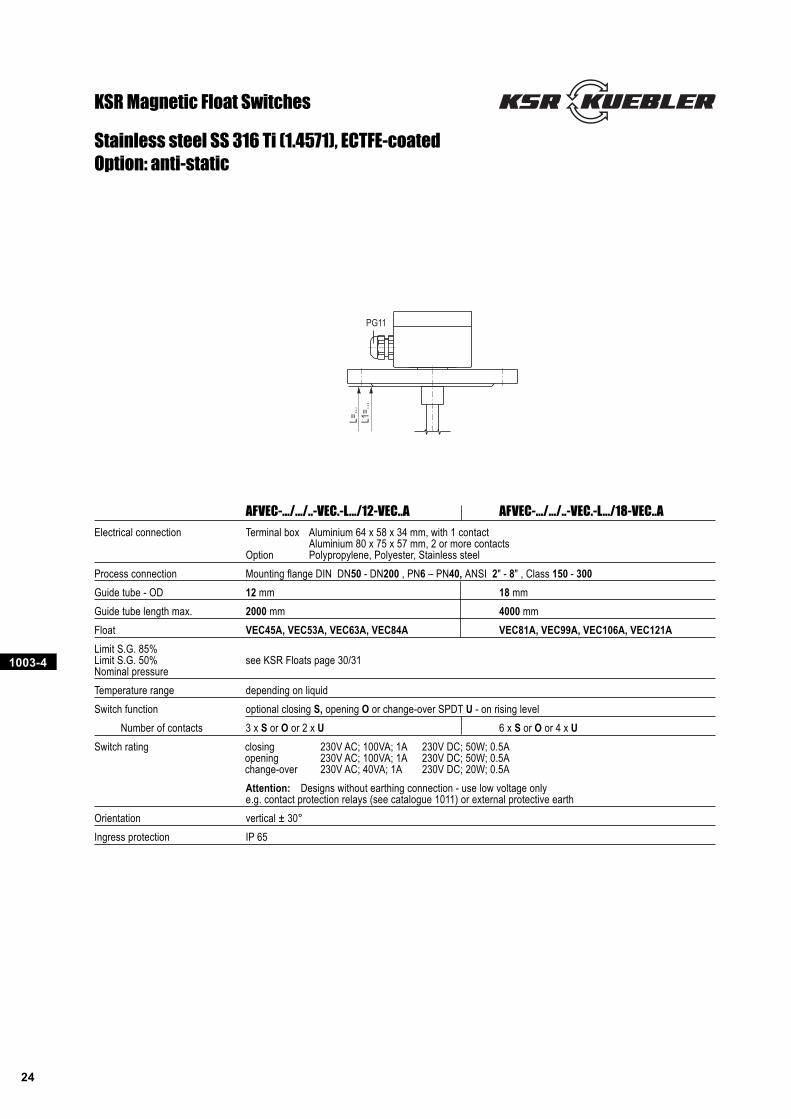
Stainless steel SS 316 Ti (1.4571), ECTFE-coatedOption: anti-static
KSR Magnetic Float Switches
AFVEC-.../.../..-VEC.-L.../12-VEC..A AFVEC-.../.../..-VEC.-L.../18-VEC..A
Electrical connection Terminal box Aluminium 64 x 58 x 34 mm, with 1 contactAluminium 80 x 75 x 57 mm, 2 or more contacts
Option Polypropylene, Polyester, Stainless steel
Process connection Mounting flange DIN DN50 - DN200 , PN6 – PN40, ANSI 2" - 8" , Class 150 - 300
Guide tube - OD 12 mm 18 mm
Guide tube length max. 2000 mm 4000 mm
Float VEC45A, VEC53A, VEC63A, VEC84A VEC81A, VEC99A, VEC106A, VEC121A
Limit S.G. 85%Limit S.G. 50% see KSR Floats page 30/31Nominal pressure
Temperature range depending on liquid
Switch function optional closing S, opening O or change-over SPDT U - on rising level
Number of contacts 3 x S or O or 2 x U 6 x S or O or 4 x U
Switch rating closing 230V AC; 100VA; 1A 230V DC; 50W; 0.5Aopening 230V AC; 100VA; 1A 230V DC; 50W; 0.5Achange-over 230V AC; 40VA; 1A 230V DC; 20W; 0.5A
Attention: Designs without earthing connection - use low voltage onlye.g. contact protection relays (see catalogue 1011) or external protective earth
Orientation vertical ± 30°
Ingress protection IP 65
1003-4
25
L=...
L1 =
...
A
B
U
A
B
L=...
L2 =
...
L1 =
...
U L=...
AB
L2 =
...
UL3
= ..
.
L1 =
...
L=...
L3 =
...
UL4
= ..
.
L2 =
...
L1 =
...
AB
AB
L=...
L4 =
...
UL5
= ..
.
L3 =
...
L2 =
... L1
= ..
.
AB
L=...
L5 =
...
UL6
= ..
.
L4 =
...
L3 =
... L2
= ..
.L1
= ..
.
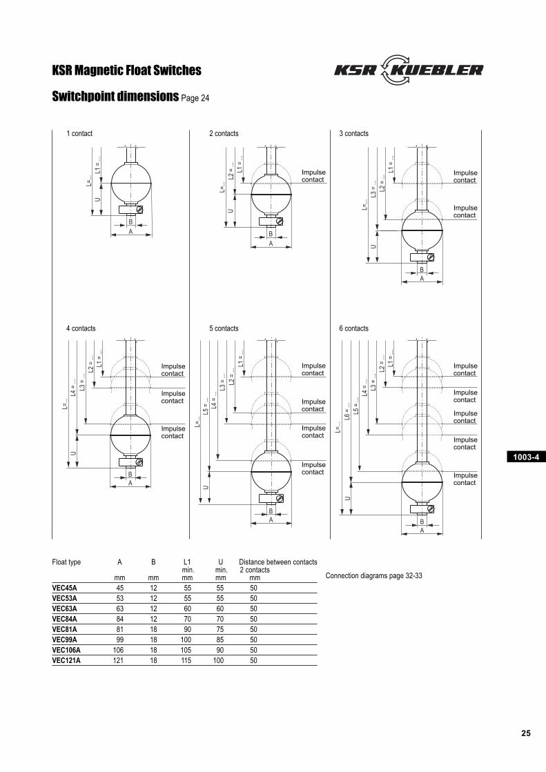
1 contact 2 contacts 3 contacts
4 contacts 5 contacts 6 contacts
Switchpoint dimensions Page 24
Connection diagrams page 32-33
KSR Magnetic Float Switches
Impulsecontact
Impulsecontact
Impulsecontact
Impulsecontact
Impulsecontact
Impulsecontact
Impulsecontact
Impulsecontact
Impulsecontact
Impulsecontact
Impulsecontact
Impulsecontact
Impulsecontact
Impulsecontact
Impulsecontact
Float type A B L1 U Distance between contactsmin. min. 2 contacts
mm mm mm mm mmVEC45A 45 12 55 55 50VEC53A 53 12 55 55 50VEC63A 63 12 60 60 50VEC84A 84 12 70 70 50VEC81A 81 18 90 75 50VEC99A 99 18 100 85 50VEC106A 106 18 105 90 50VEC121A 121 18 115 100 50
1003-4
26
L=...
L1=.
..45
551
506,
5
5580
Ø12
Ø40
A
KB
L=...
L1=.
..45
575
Ø1244
74 605,
5
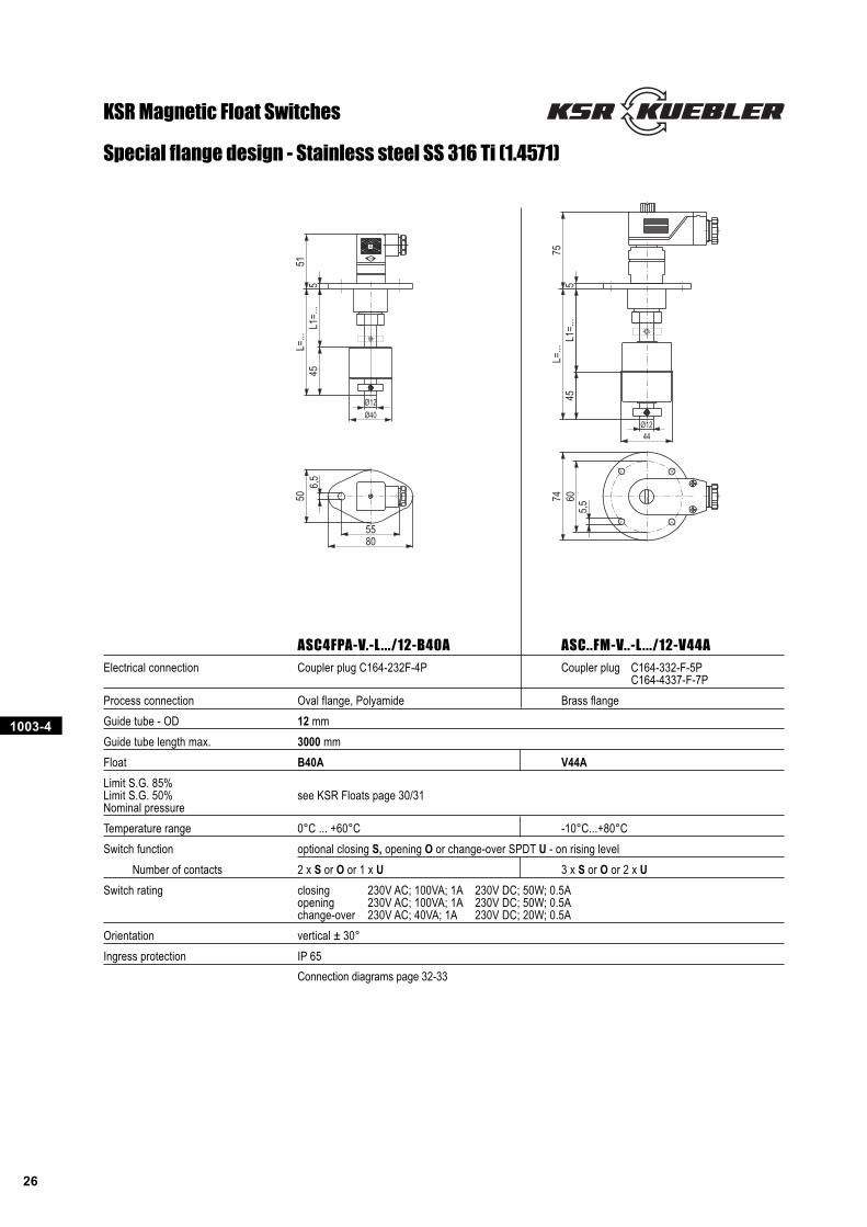
Special flange design - Stainless steel SS 316 Ti (1.4571)
KSR Magnetic Float Switches
ASC4FPA-V.-L.../12-B40A ASC..FM-V..-L .../12-V44A
Electrical connection Coupler plug C164-232F-4P Coupler plug C164-332-F-5PC164-4337-F-7P
Process connection Oval flange, Polyamide Brass flange
Guide tube - OD 12 mm
Guide tube length max. 3000 mm
Float B40A V44A
Limit S.G. 85%Limit S.G. 50% see KSR Floats page 30/31Nominal pressure
Temperature range 0°C ... +60°C -10°C...+80°C
Switch function optional closing S, opening O or change-over SPDT U - on rising level
Number of contacts 2 x S or O or 1 x U 3 x S or O or 2 x U
Switch rating closing 230V AC; 100VA; 1A 230V DC; 50W; 0.5Aopening 230V AC; 100VA; 1A 230V DC; 50W; 0.5Achange-over 230V AC; 40VA; 1A 230V DC; 20W; 0.5A
Orientation vertical ± 30°
Ingress protection IP 65
Connection diagrams page 32-33
1003-4
27
PG 9
G 11/2"
G 2"
Ø 44 mm
Ø 44 mm
Ø 40Ø12
7555
130
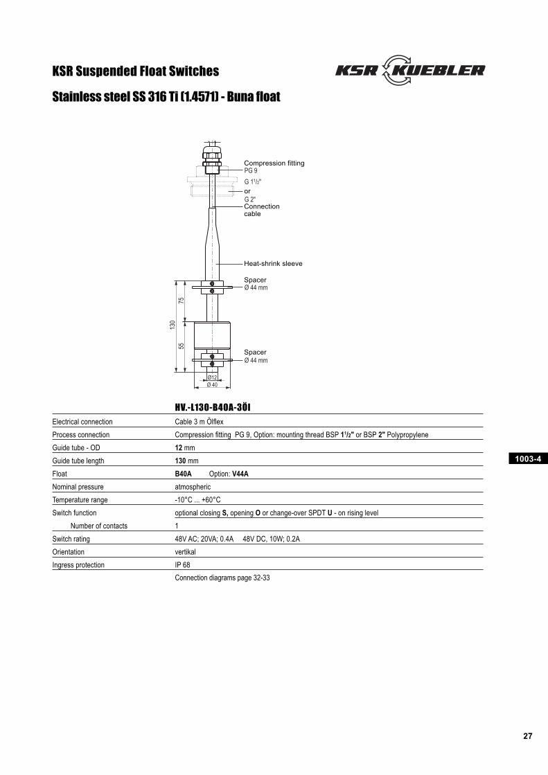
HV.-L130-B40A-3Öl
Electrical connection Cable 3 m Ölflex
Process connection Compression fitting PG 9, Option: mounting thread BSP 11/2" or BSP 2" Polypropylene
Guide tube - OD 12 mm
Guide tube length 130 mm
Float B40A Option: V44A
Nominal pressure atmospheric
Temperature range -10°C ... +60°C
Switch function optional closing S, opening O or change-over SPDT U - on rising level
Number of contacts 1
Switch rating 48V AC; 20VA; 0.4A 48V DC, 10W; 0.2A
Orientation vertikal
Ingress protection IP 68
Connection diagrams page 32-33
Stainless steel SS 316 Ti (1.4571) - Buna float
KSR Suspended Float Switches
Heat-shrink sleeve
Connectioncable
Compression fitting
Spacer
or
Spacer
1003-4
28
G 1/4"
5527
,537
,566
64
~100
27,5
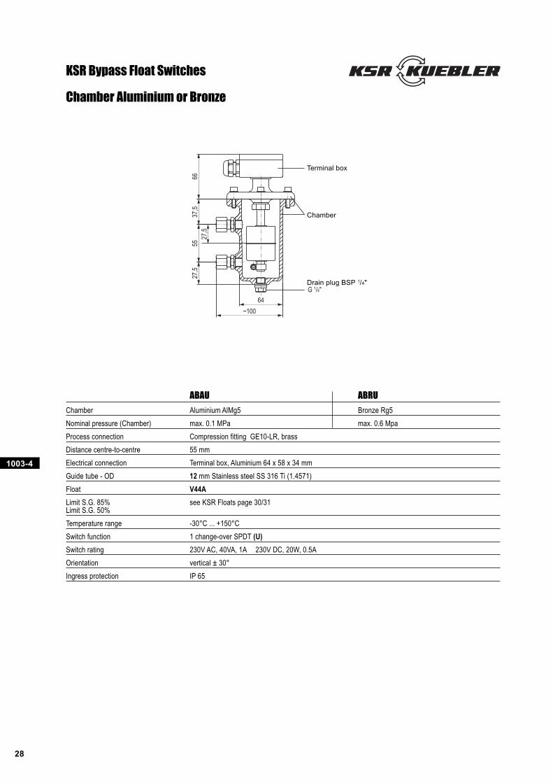
Chamber Aluminium or Bronze
ABAU ABRU
Chamber Aluminium AlMg5 Bronze Rg5
Nominal pressure (Chamber) max. 0.1 MPa max. 0.6 Mpa
Process connection Compression fitting GE10-LR, brass
Distance centre-to-centre 55 mm
Electrical connection Terminal box, Aluminium 64 x 58 x 34 mm
Guide tube - OD 12 mm Stainless steel SS 316 Ti (1.4571)
Float V44A
Limit S.G. 85% see KSR Floats page 30/31Limit S.G. 50%
Temperature range -30°C ... +150°C
Switch function 1 change-over SPDT (U)
Switch rating 230V AC, 40VA, 1A 230V DC, 20W, 0.5A
Orientation vertical ± 30°
Ingress protection IP 65
KSR Bypass Float Switches
Chamber
Drain plug BSP 1/4"
Terminal box
1003-4
29
50 Ø 60,3
L1=.
..60
M=.
..79
(102
)70
G 1/2"
M =
...55
27,5
Ø 60,350
72(9
5)L1
=...
G 1/2"
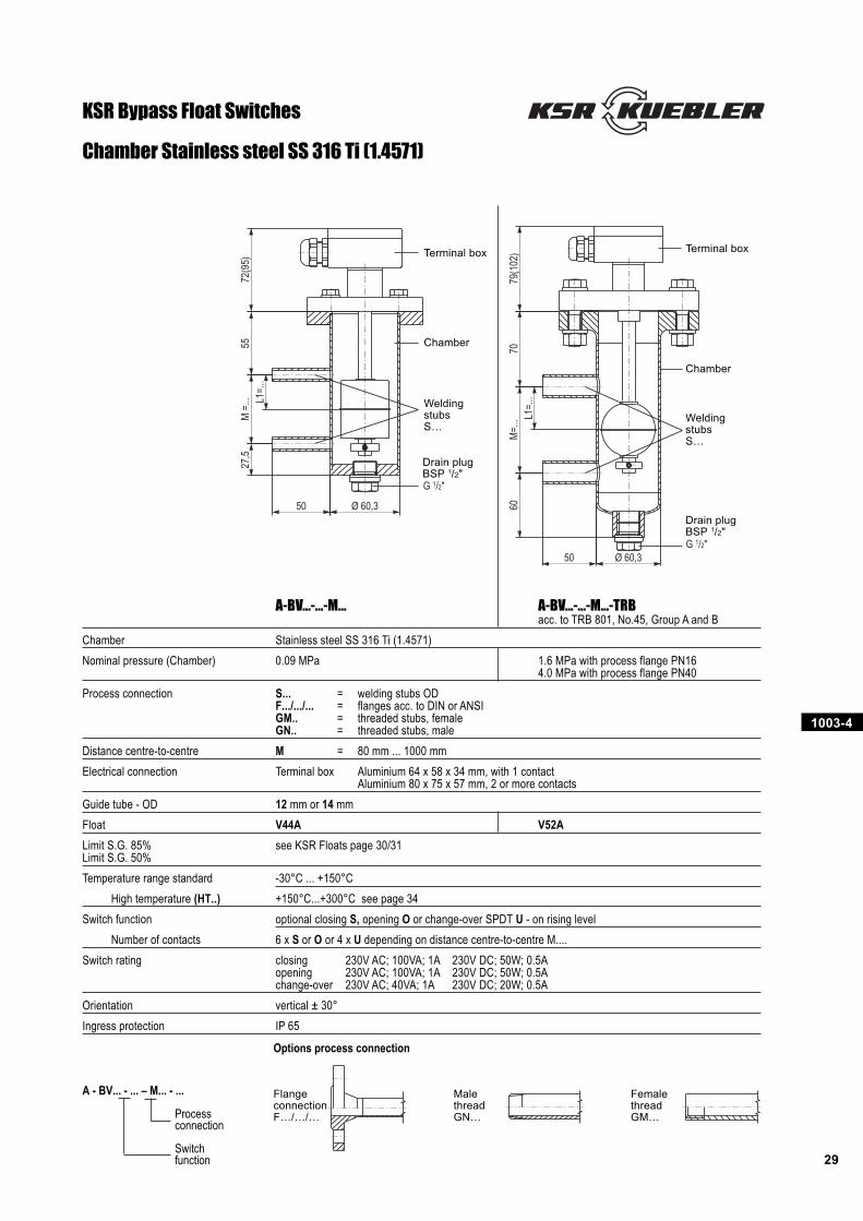
Chamber Stainless steel SS 316 Ti (1.4571)
KSR Bypass Float Switches
Options process connection
FlangeconnectionF…/…/…
MalethreadGN…
FemalethreadGM…
A-BV...-...-M... A-BV...-...-M...-TRBacc. to TRB 801, No.45, Group A and B
Chamber Stainless steel SS 316 Ti (1.4571)
Nominal pressure (Chamber) 0.09 MPa 1.6 MPa with process flange PN164.0 MPa with process flange PN40
Process connection S... = welding stubs ODF.../.../... = flanges acc. to DIN or ANSIGM.. = threaded stubs, femaleGN.. = threaded stubs, male
Distance centre-to-centre M = 80 mm ... 1000 mm
Electrical connection Terminal box Aluminium 64 x 58 x 34 mm, with 1 contactAluminium 80 x 75 x 57 mm, 2 or more contacts
Guide tube - OD 12 mm or 14 mm
Float V44A V52A
Limit S.G. 85% see KSR Floats page 30/31Limit S.G. 50%
Temperature range standard -30°C ... +150°C
High temperature (HT..) +150°C...+300°C see page 34
Switch function optional closing S, opening O or change-over SPDT U - on rising level
Number of contacts 6 x S or O or 4 x U depending on distance centre-to-centre M....
Switch rating closing 230V AC; 100VA; 1A 230V DC; 50W; 0.5Aopening 230V AC; 100VA; 1A 230V DC; 50W; 0.5Achange-over 230V AC; 40VA; 1A 230V DC; 20W; 0.5A
Orientation vertical ± 30°
Ingress protection IP 65
A - BV... - ... – M... - ...
Processconnection
Switchfunction
WeldingstubsS…
Drain plugBSP 1/2"
Terminal box
Chamber
WeldingstubsS…
Drain plugBSP 1/2"
Terminal box
Chamber
1003-4
30
D
E
Ø C
Ø A
B
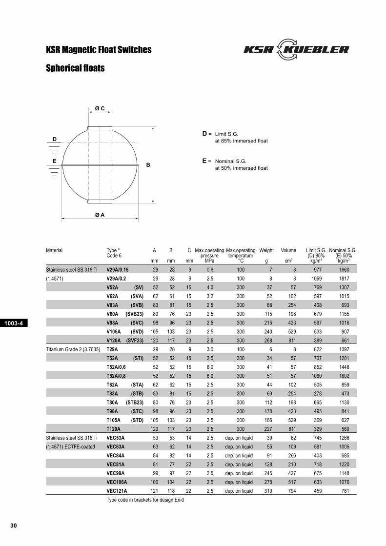
D = Limit S.G.
at 85% immersed float
E = Nominal S.G.
at 50% immersed float
Spherical floats
KSR Magnetic Float Switches
Material Type * A B C Max.operating Max.operating Weight Volume Limit S.G. Nominal S.G.Code 6 pressure temperature (D) 85% (E) 50%
mm mm mm MPa °C g cm3 kg/m3 kg/m3
Stainless steel SS 316 Ti V29A/0.15 29 28 9 0.6 100 7 8 977 1660
(1.4571) V29A/0.2 29 28 9 2.5 100 8 8 1069 1817
V52A (SV) 52 52 15 4.0 300 37 57 769 1307
V62A (SVA) 62 61 15 3.2 300 52 102 597 1015
V83A (SVB) 83 81 15 2.5 300 88 254 408 693
V80A (SVB23) 80 76 23 2.5 300 115 198 679 1155
V98A (SVC) 98 96 23 2.5 300 215 423 597 1016
V105A (SVD) 105 103 23 2.5 300 240 529 533 907
V120A (SVF23) 120 117 23 2.5 300 268 811 389 661
Titanium Grade 2 (3.7035) T29A 29 28 9 3.0 100 6 8 822 1397
T52A (STi) 52 52 15 2.5 300 34 57 707 1201
T52A/0,6 52 52 15 6.0 300 41 57 852 1448
T52A/0,8 52 52 15 8.0 300 51 57 1060 1802
T62A (STA) 62 62 15 2.5 300 44 102 505 859
T83A (STB) 83 81 15 2.5 300 60 254 278 473
T80A (STB23) 80 76 23 2.5 300 112 198 665 1130
T98A (STC) 98 96 23 2.5 300 178 423 495 841
T105A (STD) 105 103 23 2.5 300 166 529 369 627
T120A 120 117 23 2.5 300 227 811 329 560
Stainless steel SS 316 Ti VEC53A 53 53 14 2.5 dep. on liquid 39 62 745 1266
(1.4571) ECTFE-coated VEC63A 63 62 14 2.5 dep. on liquid 55 109 591 1005
VEC84A 84 82 14 2.5 dep. on liquid 91 266 403 685
VEC81A 81 77 22 2.5 dep. on liquid 128 210 718 1220
VEC99A 99 97 22 2.5 dep. on liquid 245 427 675 1148
VEC106A 106 104 22 2.5 dep. on liquid 278 517 633 1076
VEC121A 121 118 22 2.5 dep. on liquid 310 794 459 781
Type code in brackets for design Ex-0
1003-4
31
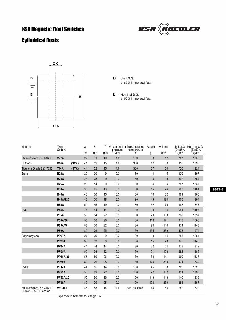
D
E
Ø C
Ø A
B
D = Limit S.G.
at 85% immersed float
E = Nominal S.G.
at 50% immersed float
KSR Magnetic Float Switches
Cylindrical floats
Material Type * A B C Max.operating Max.operating Weight Volume Limit S.G. Nominal S.G.Code 6 pressure temperature (D) 85% (E) 50%
mm mm mm MPa °C g cm3 kg/m3 kg/m3
Stainless steel SS 316 Ti V27A 27 31 10 1.6 100 8 12 787 1338
(1.4571) V44A (SVK) 44 52 15 1.6 300 42 60 818 1390
Titanium Grade 2 (3.7035) T44A (STK) 44 52 15 1.6 300 37 60 720 1224
Buna B20A 20 20 9 0.3 80 4 5 939 1597
B23A 23 25 9 0.3 80 6 9 802 1364
B25A 25 14 9 0.3 80 4 6 787 1337
B30A 30 45 13 0.3 80 15 26 683 1161
B40A 40 30 15 0.3 80 16 32 581 988
B40A/120 40 120 15 0.3 80 45 130 409 694
B50A 50 45 19 0.3 80 32 76 498 847
PVC P44A 44 44 14 0.3 60 30 54 651 1107
P55A 55 54 22 0.3 60 70 103 798 1357
P55A/26 55 80 26 0.3 60 110 141 919 1563
P55A/70 55 70 22 0.3 60 80 140 674 1145
P80A 80 79 25 0.3 60 165 339 573 974
Polypropylene PP27A 27 29 9 0.3 80 9 14 755 1284
PP35A 35 33 9 0.3 80 15 26 675 1148
PP44A 44 44 14 0.3 80 22 54 478 812
PP55A 55 54 22 0.3 80 51 103 582 989
PP55A/26 55 80 26 0.3 80 80 141 669 1137
PP80A 80 79 25 0.3 80 124 339 431 732
PVDF PF44A 44 55 14 0.3 100 45 68 782 1329
PF55A 55 69 22 0.3 100 92 132 821 1396
PF55A/26 55 80 26 0.3 100 143 148 1140 1938
PF80A 80 79 25 0.3 100 196 339 681 1157
Stainless steel SS 316 Ti VEC45A 45 53 14 1.6 dep. on liquid 44 66 782 1329(1.4571) ECTFE-coated
Type code in brackets for design Ex-0
1003-4
32
1 switchpoint
BUBN
L1
2 switchpoints
BKBKBNBU
L1
L2
3 switchpoints
GNBNYEGYPKBU
L1
L2
L3
4 switchpoints
RDWHGNBNYEGYPKBU
L1
L2
L3
L4
5 switchpoints
BKVTRDWHGNBNYEGYPKBU
L1
L2
L3
L4
L5
6 switchpoints
GY/RDBU/RDBKVTRDWHGNBNYEGYPKBU
L1
L2
L3
L4
L5
L6
1 switchpoint
BUBN
L1
2 switchpoints
BKBKBNBU
L1
L2
3 switchpoints
BNWHYEGNBURD
L1
L2
L3
1 switchpoint
BUBN
L1
2 switchpoints
BKBKBNBU
L1
L2
3 switchpoints
BNWHYEGNBURD
L1
L2
L3
4 switchpoints
RDWHGNBNYEGYPKBU
L1
L2
L3
L4
5 switchpoints
RDWHGNBNYEGYPKBUVTCLEAR
L1
L2
L3
L4
L5
6 switchpoints
RDWHGNBNYEGYPKBUVTCLEARBKOG
L1
L2
L3
L4
L5
L6
1 switchpoint
BUBNBK
L1
2 switchpoints
YEGNBNBUPKGY
L1
L2
3 switchpoints
BU/RDRDWHYEGNBNBUPKGY
L1
L2
L3
4 switchpoints
GY/RDBKVTBU/RDRDWHYEGNBNBUPKGY
L1
L2
L3
L4
1 switchpoint
BUBNBK
L1
2 switchpoints
YEGNBNBURDWH
L1
L2
1 switchpoint
BUBNBK
L1
2 switchpoints
YEGNBNBURDWH
L1
L2
3 switchpoints
WHBKOGYEGNBNBUPKGY
L1
L2
L3
4 switchpoints
WHBKOGYEGNBNBUPKGYRDVTCLEAR
L1
L2
L3
L4
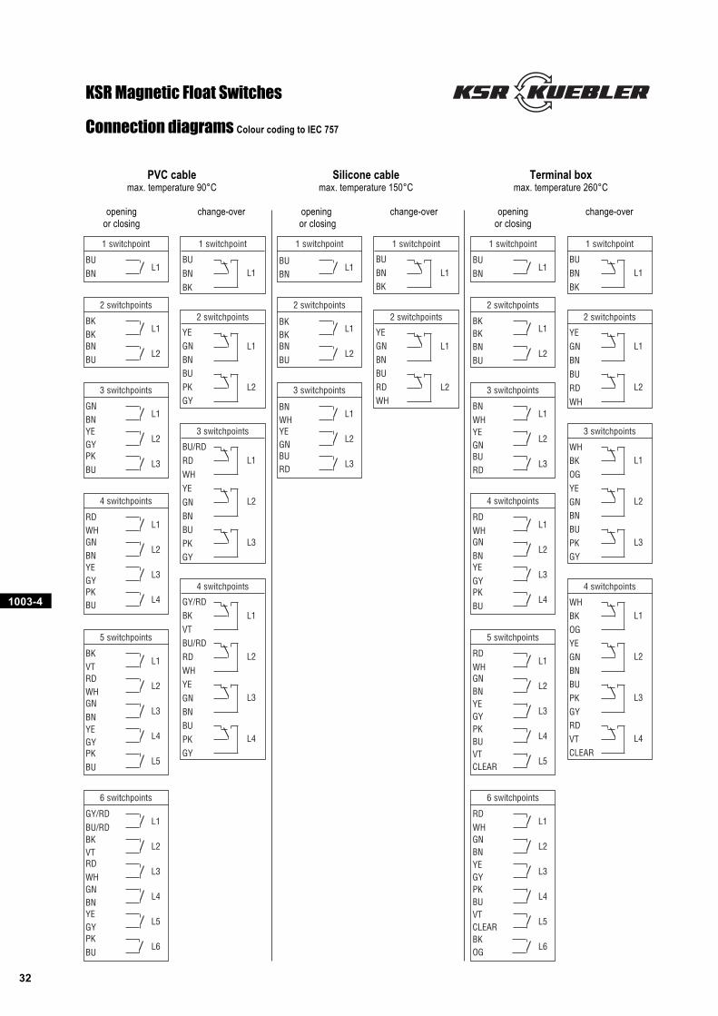
PVC cable Silicone cable Terminal boxmax. temperature 90°C max. temperature 150°C max. temperature 260°C
opening change-over opening change-over opening change-overor closing or closing or closing
Connection diagrams Colour coding to IEC 757
KSR Magnetic Float Switches
1003-4
33
1 switchpoint
128
1 Levelcontact2 Temp switches
BNWHYEGNBURD
1 Levelcontact1 Temp switch
1
2345
1 Levelcontact2 Temp switches
BU/RDRDWHYEGN
PKGY
L1
�55 °C
�75 °C
1 Levelcontact2 Temp switches
GNBNYEGYPKBU
L1
�55 °C
�75 °C
2 switchpoints
1234
L1
L2
3 switchpoints
123456
L1
L2
L3
1 switchpoint
12
L1
5P and 7P 5P and 7P
7P
5P and 7P
7P
2 switchpoints
2
1
3
L1
L2
1 switchpoint
12 L1 L1
2 switchpoint
12348
L1
L2
3 switchpoints
1234568
L1
L2
L3
1 switchpoint
123
L1
2 switchpoints
123456
L1
L2
1 switchpoint
1
3
2
L1
1 switchpoint
1238
L1
2 switchpoints
1234568
L1
L2
1 Levelcontact1 Temp switch
BKBKBNBU
L1
�
L1
�55 °C
�75 °C
1 Levelcontact1 Temp switch
2
13
L1
�
1 Levelcontact1 Temp switch
1234
L1
�
1 Levelcontact1 Temp switch
BURDWHBNGN
L1
�
L1
�
1 Levelcontact2 Temp switches
WHBKOG
GNBNBUPK
L1
�55 °C
�75 °C
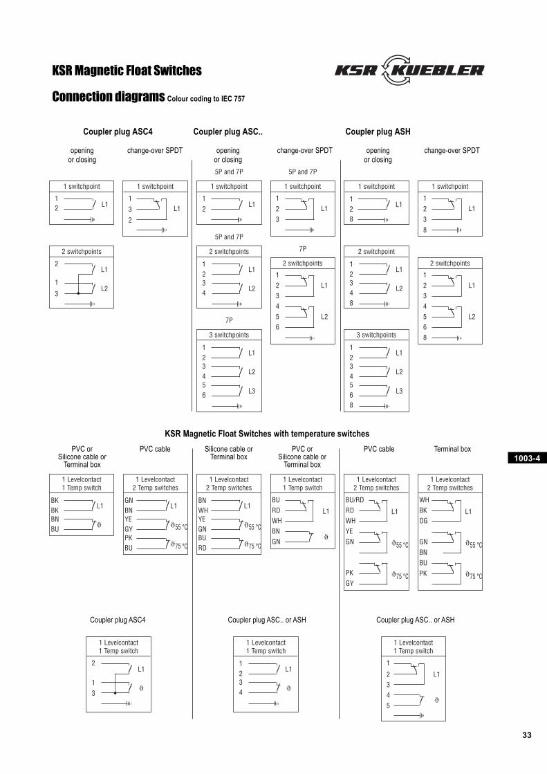
Coupler plug ASC4 Coupler plug ASC.. Coupler plug ASH
opening change-over SPDT opening change-over SPDT opening change-over SPDTor closing or closing or closing
PVC or PVC cable Silicone cable or PVC or PVC cable Terminal boxSilicone cable or Terminal box Silicone cable or
Terminal box Terminal box
KSR Magnetic Float Switches with temperature switches
Coupler plug ASC4 Coupler plug ASC.. or ASH Coupler plug ASC.. or ASH
KSR Magnetic Float Switches
Connection diagrams Colour coding to IEC 757
1003-4
34
2 00
I
S1
24 - 230V ACR
C
S1
24 - 250V DC
+
–
S1 RS+
–
C1
SPS
24 V DC
S1 RS+
–
C1230 V AC
Electr.timer
24 V DC
S1
C
RM
RE
3-10
1
2
3
4
I (A)
t (�s)
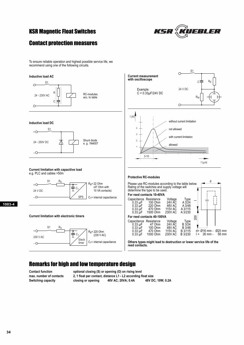
dProtective RC-modules
Please use RC-modules according to the table below.Rating of the switches and supply voltage willdetermine the type to be used.For reed contacts 10-40VACapacitance Resistance Voltage Type
0.33 µF 100 Ohm 24V AC A 3/240.33 µF 220 Ohm 48V AC A 3/480.33 µF 470 Ohm 115V AC A 3/1150.33 µF 1500 Ohm 230V AC A 3/230
For reed contacts 40-100VACapacitance Resistance Voltage Type
0.33 µF 47 Ohm 24V AC B 3/240.33 µF 100 Ohm 48V AC B 3/480.33 µF 470 Ohm 115V AC B 3/1150.33 µF 1000 Ohm 230V AC B 3/230
Others types might lead to destruction or lower service life of thereed contacts.
Remarks for high and low temperature designContact function optional closing (S) or opening (O) on rising levelmax. number of contacts 2, 1 float per contact, distance L1 - L2 according float sizeSwitching capacity closing or opening 48V AC; 20VA; 0.4A 48V DC; 10W; 0.2A
Inductive load DC
Current limitation with capacitive loade.g. PLC and cables >50m
Current limitation with electronic timers
Inductive load AC
To ensure reliable operation and highest possible service life, werecommend using one of the following circuits.
Contact protection measures
Current measurementwith oscilloscope
Example:C = 0.33µF/24V DCRC-modules
acc. to table
Shunt diodee. g. 1N4007
without current limitation
not allowed
with current limitation
allowed
Rs= 220 Ohm(230 V AC)
C1= internal capacitance
Rs= 22 Ohm(47 Ohm with10 VA contacts)
C1= internal capacitance
KSR Magnetic Float Switches
d= Ø16 mm - Ø25 mmI = 26 mm - 58 mm
KSR-KUEBLER Niveau-Messtechnik AG
69439 ZwingenbergGermanyTel ++ 49 (0) 62 63-87- 0Fax ++ 49 (0) 62 63-87 99