Embed Size (px)
Citation preview
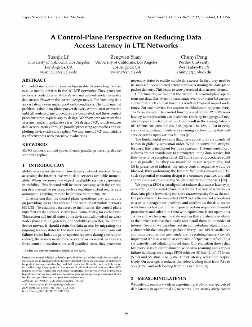
A Control-Plane Perspective on Reducing DataAccess Latency in LTE Networks
Yuanjie Li∗University of California, Los Angeles
Los Angeles, [email protected]
Zengwen Yuan∗University of California, Los Angeles
Los Angeles, [email protected]
Chunyi PengPurdue UniversityWest Lafayette, [email protected]
ABSTRACTControl-plane operations are indispensable to providing data ac-cess to mobile devices in the 4G LTE networks. They provisionnecessary control states at the device and network nodes to enabledata access. However, the current design may suffer from long dataaccess latency even under good radio conditions. The fundamentalproblem is that, data-plane packet delivery cannot start or resumeuntil all control-plane procedures are completed, and these controlprocedures run sequentially by design. We show both aremore thannecessary under popular use cases. We design DPCM, which reducesdata access latency through parallel processing approaches and ex-ploiting device-side state replica. We implement DPCM and validateits effectiveness with extensive evaluations.
KEYWORDS4G/5G network, control plane, latency, parallel processing, device-side state replica
1 INTRODUCTIONMobile users want always-on, low-latency network services. Whenaccessing the Internet, we want data services available immedi-ately. When we move, we expect negligible service suspensionin mobility. This demand will be more pressing with the emerg-ing delay-sensitive services, such as real-time virtual reality, safeautonomous driving, remote healthcare monitoring, etc.
In achieving this, the control plane operations play a vital roleon providing users data access in the state-of-art mobile network(4G LTE). To establish data access to the Internet, the control planemust first create a service session (aka. connectivity) for each device.This session will install states at the device and all involved networknodes (base station, gateway, and mobility controller). When thedevice moves, it should retain the data access by migrating theongoing session states to the user’s new location. Upon transientfailures (radio link outage, or rejected requests during control pro-cedure), the session needs to be recovered or recreated. In all cases,these control procedures are well justified, since they provision∗The first two authors contribute equally to this work.
Permission to make digital or hard copies of all or part of this work for personal orclassroom use is granted without fee provided that copies are not made or distributedfor profit or commercial advantage and that copies bear this notice and the full citationon the first page. Copyrights for components of this work owned by others than ACMmust be honored. Abstracting with credit is permitted. To copy otherwise, or republish,to post on servers or to redistribute to lists, requires prior specific permission and/or afee. Request permissions from [email protected] ’17, October 16–20, 2017, Snowbird, UT, USA© 2017 Association for Computing Machinery.ACM ISBN 978-1-4503-4916-1/17/10. . . $15.00https://doi.org/10.1145/3117811.3117838
necessary states to enable mobile data access. In fact, they need tobe successfully completed before starting/resuming the data-planepacket delivery. This leads to user-perceived data access latency.
Unfortunately, we find that the current LTE control-plane opera-tions are slow. Our 19-month user study over four major US carriersshows that, such control functions result in frequent impact on la-tency. For each device, the session establishment happens every106.9s on average. The control functions contributes 72.5–999.6 mslatency to every session establishment, resulting in aggregated neg-ative impacts. Such control functions result in the average latencyof 168.7ms, 901.6ms and 0.8–3.0s (up to 1.1s, 1.9s, 11.0s) in everyservice establishment, wide-area roaming via location update andservice access upon various failures (§2).
The fundamental reason is that, these procedures are mandatedto run in globally sequential order. While intuitive and straight-forward, this is inefficient for three reasons: (1) Some control pro-cedures are not mandatory to starting/resuming data service, butthey have to be completed first; (2) Some control procedures couldrun in parallel, but they are mandated to run sequentially; and(3) In presence of failures, the entire control sequence would beblocked, thus prolonging the latency. While discovered 4G LTE,such sequential execution design is a common practice, and stillcontinues in various ongoing 5G standardization proposals [18].
We propose DPCM, a paradigm that reduces data access latency byaccelerating the control-plane operations. The key observation isthat, data-plane forwarding can startwithoutwaiting for all the con-trol procedures to be completed. DPCM treats the control proceduresas a state management problem, and accelerates the data accesswith three techniques. It first bypasses certain sequence of controlprocedures, and substitute them with equivalent, faster operations.To this end, we leverage the state replicas that are already availableat the device, retrieve them early and install them at the nodes ofinterest. Second, we pipeline certain control-plane signaling pro-cedures with the data-plane packet delivery. Last, DPCM parallelizescontrol procedures that are mandatory to retaining data service. Weimplement DPCM as a modular extension of OpenAirInterface [4], asoftware-defined cellular protocol stack. Our evaluation shows that,for every session establishment, wide-area roaming and variousfailure handling, on average DPCM achieves 88.7ms (2.1×), 735.4ms(5.8×) and 580.8ms–2.6s (7.8×–11.5×) latency reduction, respec-tively. On average, it reduces the video loading time from 9.8s to5.7s (1.7×), and web loading from 1.5s to 0.7s (2.1×).
2 MEASURING LATENCYWemotivate our workwith an experimental study of user-perceiveddata latency in operational 4G networks. Our latency study covers
Paper Session II: Can You Hear Me Now? MobiCom’17, October 16-20, 2017, Snowbird, UT, USA
56
Location Domain 1
Location Domain 2
BS (base station) Gateway MC (mobility
controller)User profile
server
Cellular network
data path Internet
Figure 1: LTE network architecture.
AT&T T-Mobile Sprint Verizon TotalMessage# 290,677 692,916 144,868 94,212 1,222,673Record# 24,053 51,620 9,632 9,752 95,057
Table 1: Dataset in the user study.
AT&T T-Mobile Sprint Verizon Total01000200030004000
Late
ncy
(ms) Service establishment (C1)
Handover (C2)Wide-area roaming (C3)
Figure 2: Latency measured in major U.S. LTE operators.
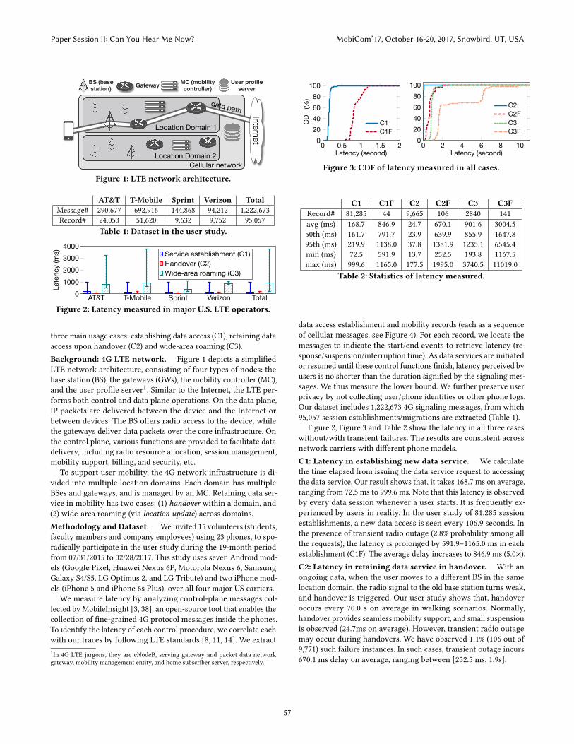
three main usage cases: establishing data access (C1), retaining dataaccess upon handover (C2) and wide-area roaming (C3).Background: 4G LTE network. Figure 1 depicts a simplifiedLTE network architecture, consisting of four types of nodes: thebase station (BS), the gateways (GWs), the mobility controller (MC),and the user profile server1. Similar to the Internet, the LTE per-forms both control and data plane operations. On the data plane,IP packets are delivered between the device and the Internet orbetween devices. The BS offers radio access to the device, whilethe gateways deliver data packets over the core infrastructure. Onthe control plane, various functions are provided to facilitate datadelivery, including radio resource allocation, session management,mobility support, billing, and security, etc.
To support user mobility, the 4G network infrastructure is di-vided into multiple location domains. Each domain has multipleBSes and gateways, and is managed by an MC. Retaining data ser-vice in mobility has two cases: (1) handover within a domain, and(2) wide-area roaming (via location update) across domains.Methodology andDataset. We invited 15 volunteers (students,faculty members and company employees) using 23 phones, to spo-radically participate in the user study during the 19-month periodfrom 07/31/2015 to 02/28/2017. This study uses seven Android mod-els (Google Pixel, Huawei Nexus 6P, Motorola Nexus 6, SamsungGalaxy S4/S5, LG Optimus 2, and LG Tribute) and two iPhone mod-els (iPhone 5 and iPhone 6s Plus), over all four major US carriers.
We measure latency by analyzing control-plane messages col-lected by MobileInsight [3, 38], an open-source tool that enables thecollection of fine-grained 4G protocol messages inside the phones.To identify the latency of each control procedure, we correlate eachwith our traces by following LTE standards [8, 11, 14]. We extract1In 4G LTE jargons, they are eNodeB, serving gateway and packet data networkgateway, mobility management entity, and home subscriber server, respectively.
0 0.5 1 1.5 20
20406080
100
Latency (second)
CDF
(%)
C1C1F
0 2 4 6 8 100
20406080
100
Latency (second)
C2C2FC3C3F
Figure 3: CDF of latency measured in all cases.
C1 C1F C2 C2F C3 C3FRecord# 81,285 44 9,665 106 2840 141avg (ms) 168.7 846.9 24.7 670.1 901.6 3004.550th (ms) 161.7 791.7 23.9 639.9 855.9 1647.895th (ms) 219.9 1138.0 37.8 1381.9 1235.1 6545.4min (ms) 72.5 591.9 13.7 252.5 193.8 1167.5max (ms) 999.6 1165.0 177.5 1995.0 3740.5 11019.0
Table 2: Statistics of latency measured.
data access establishment and mobility records (each as a sequenceof cellular messages, see Figure 4). For each record, we locate themessages to indicate the start/end events to retrieve latency (re-sponse/suspension/interruption time). As data services are initiatedor resumed until these control functions finish, latency perceived byusers is no shorter than the duration signified by the signaling mes-sages. We thus measure the lower bound. We further preserve userprivacy by not collecting user/phone identities or other phone logs.Our dataset includes 1,222,673 4G signaling messages, from which95,057 session establishments/migrations are extracted (Table 1).
Figure 2, Figure 3 and Table 2 show the latency in all three caseswithout/with transient failures. The results are consistent acrossnetwork carriers with different phone models.C1: Latency in establishing new data service. We calculatethe time elapsed from issuing the data service request to accessingthe data service. Our result shows that, it takes 168.7 ms on average,ranging from 72.5 ms to 999.6 ms. Note that this latency is observedby every data session whenever a user starts. It is frequently ex-perienced by users in reality. In the user study of 81,285 sessionestablishments, a new data access is seen every 106.9 seconds. Inthe presence of transient radio outage (2.8% probability among allthe requests), the latency is prolonged by 591.9–1165.0 ms in eachestablishment (C1F). The average delay increases to 846.9 ms (5.0×).C2: Latency in retaining data service in handover. With anongoing data, when the user moves to a different BS in the samelocation domain, the radio signal to the old base station turns weak,and handover is triggered. Our user study shows that, handoveroccurs every 70.0 s on average in walking scenarios. Normally,handover provides seamless mobility support, and small suspensionis observed (24.7ms on average). However, transient radio outagemay occur during handovers. We have observed 1.1% (106 out of9,771) such failure instances. In such cases, transient outage incurs670.1 ms delay on average, ranging between [252.5 ms, 1.9s].
Paper Session II: Can You Hear Me Now? MobiCom’17, October 16-20, 2017, Snowbird, UT, USA
57
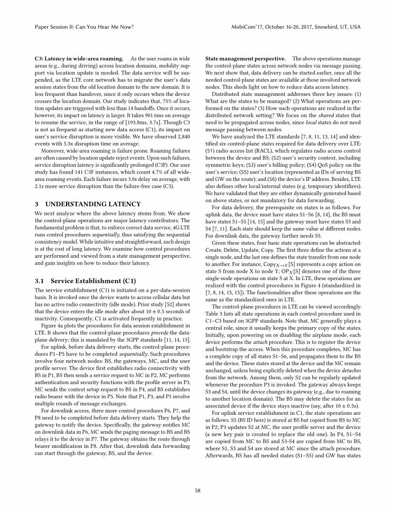
C3: Latency in wide-area roaming. As the user roams in wideareas (e.g., during driving) across location domains, mobility sup-port via location update is needed. The data service will be sus-pended, as the LTE core network has to migrate the user’s datasession states from the old location domain to the new domain. It isless frequent than handover, since it only occurs when the devicecrosses the location domain. Our study indicates that, 75% of loca-tion updates are triggered with less than 14 handoffs. Once it occurs,however, its impact on latency is larger. It takes 901.6ms on averageto resume the service, in the range of [193.8ms, 3.7s]. Though C3is not as frequent as starting new data access (C1), its impact onuser’s service disruption is more visible. We have observed 2,840events with 5.3x disruption time on average.
Moreover, wide-area roaming is failure prone. Roaming failuresare often caused by location update reject events. Upon such failures,service disruption latency is significantly prolonged (C3F). Our userstudy has found 141 C3F instances, which count 4.7% of all wide-area roaming events. Each failure incurs 3.0s delay on average, with2.1s more service disruption than the failure-free case (C3).
3 UNDERSTANDING LATENCYWe next analyze where the above latency stems from. We showthe control-plane operations are major latency contributors. Thefundamental problem is that, to enforce correct data service, 4G LTEruns control procedures sequentially, thus satisfying the sequentialconsistencymodel.While intuitive and straightforward, such designis at the cost of long latency. We examine how control proceduresare performed and viewed from a state management perspective,and gain insights on how to reduce their latency.
3.1 Service Establishment (C1)The service establishment (C1) is initiated on a per-data-sessionbasis. It is invoked once the device wants to access cellular data buthas no active radio connectivity (idle mode). Prior study [52] showsthat the device enters the idle mode after about 10 ± 0.5 seconds ofinactivity. Consequently, C1 is activated frequently in practice.
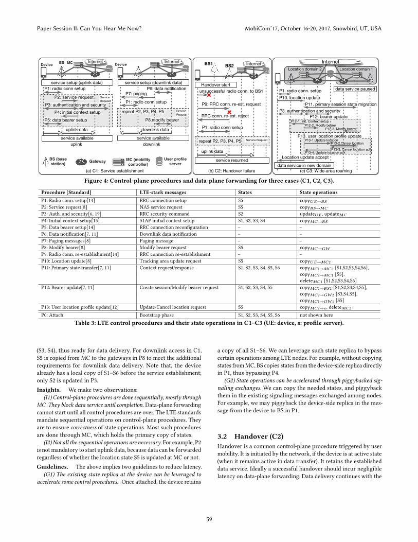
Figure 4a plots the procedures for data session establishment inLTE. It shows that the control-plane procedures precede the data-plane delivery; this is mandated by the 3GPP standards [11, 14, 15].
For uplink, before data delivery starts, the control-plane proce-dures P1–P5 have to be completed sequentially. Such proceduresinvolve four network nodes: BS, the gateways, MC, and the userprofile server. The device first establishes radio connectivity withBS in P1, BS then sends a service request to MC in P2, MC performsauthentication and security functions with the profile server in P3,MC sends the context setup request to BS in P4, and BS establishesradio bearer with the device in P5. Note that P1, P3, and P5 involvemultiple rounds of message exchanges.
For downlink access, three more control procedures P6, P7, andP8 need to be completed before data delivery starts. They help thegateway to notify the device. Specifically, the gateway notifies MCon downlink data in P6, MC sends the paging message to BS and BSrelays it to the device in P7. The gateway obtains the route throughbearer modification in P8. After that, downlink data forwardingcan start through the gateway, BS, and the device.
Statemanagement perspective. The above operationsmanagethe control-plane states across network nodes via message passing.We next show that, data delivery can be started earlier, once all theneeded control-plane states are available at those involved networknodes. This sheds light on how to reduce data access latency.
Distributed state management addresses three key issues: (1)What are the states to be managed? (2) What operations are per-formed on the states? (3) How such operations are realized in thedistributed network setting? We focus on the shared states thatneed to be propagated across nodes, since local states do not needmessage passing between nodes.
We have analyzed the LTE standards [7, 8, 11, 13, 14] and iden-tified six control-plane states required for data delivery over LTE:(S1) radio access list (RACL), which regulates radio access controlbetween the device and BS; (S2) user’s security context, includingsymmetric keys; (S3) user’s billing policy; (S4) QoS policy on theuser’s service; (S5) user’s location (represented as IDs of serving BSand GW on the route); and (S6) the device’s IP address. Besides, LTEalso defines other local/internal states (e.g. temporary identifiers).We have validated that they are either dynamically generated basedon above states, or not mandatory for data forwarding.
For data delivery, the prerequisite on states is as follows. Foruplink data, the device must have states S1–S6 [8, 14], the BS musthave states S1–S5 [14, 15] and the gateway must have states S3 andS4 [7, 11]. Each state should keep the same value at different nodes.For downlink data, the gateway further needs S5.
Given these states, four basic state operations can be abstracted:Create, Delete, Update, Copy. The first three define the actions at asingle node, and the last one defines the state transfer from one nodeto another. For instance, CopyX→Y [S] represents a copy action onstate S from node X to node Y; OPX [S] denotes one of the threesingle-node operations on state S at X. In LTE, these operations arerealized with the control procedures in Figure 4 (standardized in[7, 8, 14, 15, 15]). The functionalities after these operations are thesame as the standardized ones in LTE.
The control-plane procedures in LTE can be viewed accordingly.Table 3 lists all state operations in each control procedure used inC1–C3 based on 3GPP standards. Note that, MC generally plays acentral role, since it usually keeps the primary copy of the states.Initially, upon powering on or disabling the airplane mode, eachdevice performs the attach procedure. This is to register the deviceand bootstrap the access. When this procedure completes, MC hasa complete copy of all states S1–S6, and propagates them to the BSand the device. These states stored at the device and the MC remainunchanged, unless being explicitly deleted when the device detachesfrom the network. Among them, only S2 can be regularly updatedwhenever the procedure P3 is invoked. The gateway always keepsS3 and S4, until the device changes its gateway (e.g., due to roamingto another location domain). The BS may delete the states for anassociated device if the device stays inactive (say, after 10 ± 0.5s).
For uplink service establishment in C1, the state operations areas follows. S5 (BS ID here) is stored at BS but copied from BS to MCin P2; P3 updates S2 at MC, the user profile server and the device(a new key pair is created to replace the old one). In P4, S1–S4are copied from MC to BS and S3-S4 are copied from MC to BS,where S1, S3 and S4 are stored at MC since the attach procedure.Afterwards, BS has all needed states (S1–S5) and GW has states
Paper Session II: Can You Hear Me Now? MobiCom’17, October 16-20, 2017, Snowbird, UT, USA
58
(c) C3: Wide-area roaming(b) C2: Handover failure(a) C1: Service establishment
downlinkuplinkservice available
service setup (downlink data)
repeat P2, P3, P4, P5
P6: data notificationP7: paging
P1: radio conn setup
P8.modify bearer
Service Request
downlink data
Device Internet
Handover start
service resumed
Service Request
RRC conn. re-est. reject
P1: radio conn setup
unsuccessful radio conn. to BS1
P9: RRC conn. re-est request
repeat P2, P3, P4, P5
×
×
BS1 BS2
uplink data
Internet
uplink data
Device
P3: authentication and securityP2
P5: data bearer setup
P1: radio conn setup
P4: initial context setup
Service Request
Internet
service setup (uplink data)
service available
BS MCLocation domain 2 Location domain 1
Internet
P13. user location profile update
P1. radio conn. setupP10. location update
P11. primary session state migrationP3. authentication and security
P12. bearer update
Location update accept
data service in new domain
data service paused
P13-1.Update locationP13-2.Cancel location
P13-4. Update location ackP13-3. Cancel location ack
P12-1. Init. Context setupP12-2. Modify bearer
P12-3. Modify bearer
BS (base station) Gateway MC (mobility
controller)User profile
server
Figure 4: Control-plane procedures and data-plane forwarding for three cases (C1, C2, C3).
Procedure [Standard] LTE-stack messages States State operationsP1: Radio conn. setup[14] RRC connection setup S5 copyU E→BSP2: Service request[8] NAS service request S5 copyBS→MCP3: Auth. and security[6, 19] RRC security command S2 updateU E , updateMCP4: Initial context setup[15] S1AP initial context setup S1, S2, S3, S4 copyMC→BSP5: Data bearer setup[14] RRC connection reconfiguration – –P6: Data notification[7, 11] Downlink data notification – –P7: Paging messages[8] Paging message – –P8: Modify bearer[8] Modify bearer request S5 copyMC→GWP9: Radio conn. re-establishment[14] RRC connection re-establishment – –P10: Location update[8] Tracking area update request S5 copyU E→MC2P11: Primary state transfer[7, 11] Context request/response S1, S2, S3, S4, S5, S6 copyMC1→MC2 [S1,S2,S3,S4,S6],
copyMC2→MC1 [S5],deleteMC1 [S1,S2,S3,S4,S6]
P12: Bearer update[7, 11] Create session/Modify bearer request S1, S2, S3, S4, S5 copyMC2→BS2 [S1,S2,S3,S4,S5],copyMC2→GW 2 [S3,S4,S5],copyMC1→GW 1 [S5]
P13: User location profile update[12] Update/Cancel location request S5 copyMC2→s , deleteMC2
P0: Attach Bootstrap phase S1, S2, S3, S4, S5, S6 not shown hereTable 3: LTE control procedures and their state operations in C1–C3 (UE: device, s: profile server).
(S3, S4), thus ready for data delivery. For downlink access in C1,S5 is copied from MC to the gateways in P8 to meet the additionalrequirements for downlink data delivery. Note that, the devicealready has a local copy of S1–S6 before the service establishment;only S2 is updated in P3.Insights. We make two observations:
(I1) Control-plane procedures are done sequentially, mostly throughMC. They block data service until completion. Data-plane forwardingcannot start until all control procedures are over. The LTE standardsmandate sequential operations on control-plane procedures. Theyare to ensure correctness of state operations. Most such proceduresare done through MC, which holds the primary copy of states.
(I2) Not all the sequential operations are necessary. For example, P2is not mandatory to start uplink data, because data can be forwardedregardless of whether the location state S5 is updated at MC or not.Guidelines. The above implies two guidelines to reduce latency.
(G1) The existing state replica at the device can be leveraged toaccelerate some control procedures. Once attached, the device retains
a copy of all S1–S6. We can leverage such state replica to bypasscertain operations among LTE nodes. For example, without copyingstates fromMC, BS copies states from the device-side replica directlyin P1, thus bypassing P4.
(G2) State operations can be accelerated through piggybacked sig-naling exchanges. We can copy the needed states, and piggybackthem in the existing signaling messages exchanged among nodes.For example, we may piggyback the device-side replica in the mes-sage from the device to BS in P1.
3.2 Handover (C2)Handover is a common control-plane procedure triggered by usermobility. It is initiated by the network, if the device is at active state(when it remains active in data transfer). It retains the establisheddata service. Ideally a successful handover should incur negligiblelatency on data-plane forwarding. Data delivery continues with the
Paper Session II: Can You Hear Me Now? MobiCom’17, October 16-20, 2017, Snowbird, UT, USA
59
old BS when the network initiates handover. Data forwarding pro-ceeds with the new BS after the handover. Interestingly, handoveris initiated by the device if at the idle mode.
We examine latency in handover upon state operation failures(C2F). Figure 4b plots an example incurred by transient radio outage.Assume the planned handover for the device is to BS1. However, ifthe signal suddenly turns weak, this handover to the new BS1 willnot succeed. Due to this handover failure and its lost connectivitywith the old BS upon handover, the device selects another newBS2 (with strong radio signal) for handover. Radio connectivity toBS2 then needs to be reestablished for data access in P9. However,such a RRC re-establishment request would be rejected, becausethe device has never established radio connectivity with BS2 apriori. It thus incurs a control-plane operation failure. To cope withsuch a failure, the device has to run the entire sequence of serviceestablishment procedures (C1) from P1 to P5, and the data servicewill be suspended in between. Moreover, our user study shows that,this type of transient radio link outage is regularly observed inoperational LTE networks.State management perspective. The long delay is actuallycaused by running the needed state operations sequentially. Whenthe newly selected BS2 receives the RRC data service request inP9, it needs to have necessary states (S1–S5) to provide services.Without such states, BS2 has to reject the request and report afailure. However, copying states (S1–S5) from BS1 to BS2 is notsupported by the current LTE standards. Copying from the old BSis neither an option, since it may have deleted all states after theplanned handover to BS1. So BS2 has to let the device initiate theservice establishment process (C1), to copy those states from MC. Itcan only start to offer data access after completing all operations.Insight. We make another observation:
(I3) Lengthy control-plane operations can be triggered by transientradio link outage, thus incurring prolonged latency. The link outageduring handover invokes the connectivity re-establishment requestfrom the device (P9), which is rejected by BS2. The rejection furtherincurs lengthy operations P1–P5 and extra latency.Guideline. We come up with another design rule:
(G3) State replica can help to avoid state operation failures. Theavailable state replica at the device may help to eliminate controloperation failures. In this case, the connection reestablishment failssince BS2 cannot copy the connectivity state from BS1. Instead, thenewly selected BS2 can obtain the correct state replica from thedevice via the connection reestablishment request. This way, BS2offers service immediately.
3.3 Wide-Area Roaming (C3)In C3, location update is invoked when the user moves to a newlocation domain. In this case, a sequence of control-plane proce-dures are executed to resume its data service in the new domain, asshown in Figure 4c. Upon radio connectivity setup in P1, the devicereports its arrival to the new MC (i.e., MC2) in P10. The new MCmigrates states from the old MC, and notifies the device’s locationto the old MC in P11. Authentication and security procedure (P3) isapplied again to the device. To resume data service, a data bearer(spanning the new BS/gateways, and old gateways) is sequentiallyupdated in P12: The new MC initializes the bearer context at the
new BS (P12-1), and modifies the new gateway’s bearer (P12-2).Afterwards, the old MC also reconfigures the old gateway (P12-3),which then can relay its buffered downlink data to the device (viatunneling). The user’s latest location is recorded at the profile serverand deleted at the old MC in P13: The new MC updates the profileserver (P13-1), which then notifies the old MC to delete the device’slocation (P13-2/3) and acknowledges to the new MC (P13-4).State management perspective. To resume data delivery, thenew BS must have states (S1–S5) identical to the device’s ones, andthe new gateway should know S3 and S4 (and S5 for downlinkaccess). Moreover, the old gateway should also know the latest S5so that it can relay the buffered downlink data to the device. InP11, all states except location (S5) are deleted at the old MC afterbeing copied to the new MC, and the new MC copies S5 to the oldMC. This leads to state migration between two MCs. In P12, statesS1–S5 and S3–S5 are copied from the new MC to the new BS andthe new gateways, and state S5 is copied from the old MC to theold gateways. In P13, S5 is copied to the user profile server, anddeleted by the old MC. These operations are still done sequentially,but some are unnecessary.Insights. We make two new observations:
(I4) Certain control-plane operations are conservative and time con-suming. When updating the route, the newMC distributes the statesto the new BS and new gateways in P12. Current LTE performsstate-copying sequentially to each node.
(I5) Data-plane forwarding path is ready before the entire controlstate operations are completed. Similar to I1, the forwarding pathis updated and available after bearer update (P12). However, dataservice is suspended until the location profile update (P13) is done.Guidelines. We make two more guidelines:
(G4) Sequential state copy can be made parallel. The state-copyingoperations in P12 are safe to parallelize without write conflicts. Wethus reduce latency by parallelizing state copy to all involved nodes.
(G5) Control-plane state operations and data-plane packet forward-ing can be pipelined. Given that P13 does not involve any node onthe forwarding path, we can concurrently perform location updateto the profile server along with data forwarding. This way, serviceresumption delay is reduced.
3.4 SummaryIn summary, the control-plane operations are major latency con-tributors for all three cases. On one hand, these procedures are fullywarranted, since they provision necessary states (Table 3) to enablemobile data access. On the other hand, they take sequential opera-tions among network nodes and the device. They are ineffective inthree aspects: (A1) Certain procedures are ordered and required torun in a sequence, thus incurring long latency (see G1–G3); (A2)Some procedures are not mandatory to starting/resuming data ser-vice, but they have to be completed first (see G5); (A3) Some couldbe run in parallel, but are mandated to run sequentially (see G4).
4 DPCM DESIGNWe present DPCM, which reduces data access latency due to control-plane operations and retains the same functionalities as 4G LTE.Following the observations in §3, DPCM departs from theMC-centric,sequential design on the control plane. Instead, we leverage the
Paper Session II: Can You Hear Me Now? MobiCom’17, October 16-20, 2017, Snowbird, UT, USA
60
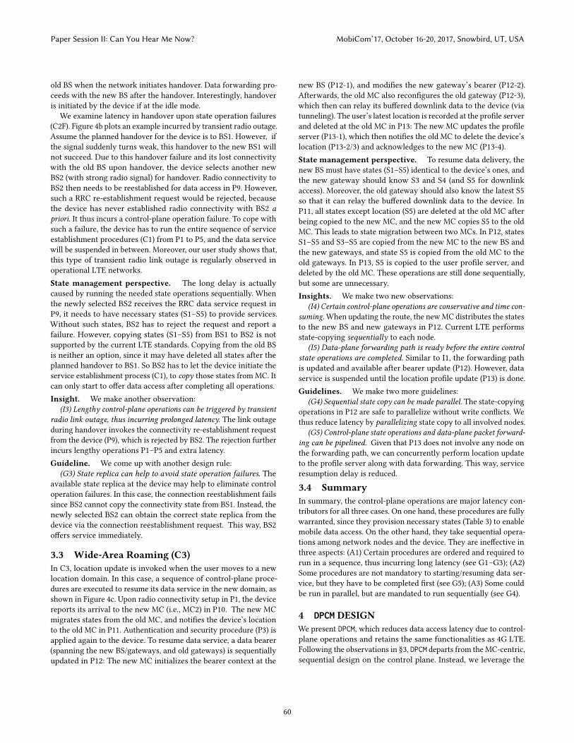
state replicas available at the device and other nodes. We thus ex-ploit short side-paths, parallelize certain control procedures, andpipeline the control-plane and data-plane operations without vio-lating correctness. This results in three concrete techniques.• Bypassing: To address A1, we first bypass certain existingsequence of control procedures, and substitute with equivalent,faster operations. Through these substituted operations, all requiredstates at the device, the BS, and the gateway should be installed be-fore data-plane forwarding. Therefore, such equivalent side-pathsenable us to install states at the involved nodes earlier, thus estab-lishing/resuming data services faster.
To realize bypassing, we seek to retrieve state replica early andinstall them at the nodes of interest. The key enabler is that, statereplicas are already available for use. Such replicas exist at thedevice and other network nodes, once the device is attached to thenetwork (see §3.1). Specifically, states S1–S6 are already stored atthe device. They remain always available, even during the device’sidle mode, unless the device is explicitly detached. In reality, theirvalues remain largely unchanged (§4.4) except for S2. Note that,S2 is updated each time P3 is executed. However, it is used forencryption over the air transfer between the device and the BS. Wecan delegate this key generation of S2 from the MC to the device.We run local key agreement procedure (by following P3) at thedevice, produce updated S2 for the device and BS, and later notifythe MC of this S2 update. We will elaborate on how to use it toreduce latency in C1–C3, and how to ensure correctness in §4.4.• Pipelining control-data: We further pipeline certain control-plane signaling procedures with the data-plane packet delivery. Thekey premise is that, data-plane forwarding can start without wait-ing for the entire sequence of control procedures to be completed(A2). Therefore, we pipeline data delivery with those latter-stagecontrol procedures. This way, data access latency is reduced. Torealize control-data pipelining, we exploit the technique of in-bandsignaling. The idea is to piggyback the control-plane states andmessages with the forwarded data packets. As data packets traverseBSes and gateways, control actions are also taken at these nodes.• Parallelizing control procedures: DPCM last parallelizes cer-tain control procedures that are mandatory to retaining data service.This addresses A3, where these control procedures are executedsequentially but could be run in parallel (e.g., route update at gate-ways and BS in C3). We thus perform concurrent state operationsby leveraging multiple replicas at different nodes.
We next show how these three techniques are applied to handleall cases C1–C3. When potential conflicts arise due to parallel andconcurrent state operations (which are deemed rather rare), wefurther present designs to cope with them all in §4.4.
4.1 Service Establishment (C1)We first use bypassing to accelerate service establishment (G1, G2).We replace the existing procedures P1–P5 with two new ones P1′and P13′ while retaining the original control functions. Note that,P13′ can be run in parallel with the data-plane forwarding, and onlyP1′ needs to be completed before data delivery starts. P1′ keepsthe same rounds of message exchanges in P1, but augments themby piggybacking needed control states. This is made possible by
uplinkstate replica downlink
Location domain 2 Location domain 1Internet
data service in new domain
data service pausedP1’: bypass P1, P10, P11, P3
P12’: Location update
P13’-1: ProposalsP13’-2: Accepts
P13’: parallel state ops
uplink data
P1’: bypass P2, P3, P4, P5
Internet
service setup (uplink data)
service available service available
service setup (downlink data)P6P7
P1’: bypass P2, P3, P4, P5
downlink data
Internet
P8’: revised procedure
Handover start
service resumed
unsuccessful radio conn.×
BS1 BS2
uplink data
Internet
P9’: new conn. re-est(no rejection)(bypass P1, P2, P3, P4, P5)
(c) C3: Wide-area roaming
(b) C2: Handover failure
(a) C1: Service establishment
Concurrentexecution
P12’-2 P12’-3
BS (base station) Gateway
MC (mobility controller)
User profile server
P12’-1
P13’: parallel state ops P13’: parallel state ops
P13’: parallel state ops
Figure 5: Solution sketch for C1, C2 and C3.
leveraging the available state replica at the device. Moreover, giventhe new P1′, P5 can be merged with it. P13′ synchronizes stateupdates at the BS, the MC and the profile server. P8 is also revisedto transfer the needed states to the gateways for downlink access.Uplink data. We skip the state copy action fromMC to BS. In thenew procedure P1′ (Figure 5a), we copy the device-side state replicato BS (following G1), by piggybacking it in the existing messages ofP1 (following G2). P1′ thus installs all required states S1–S5 at theBS. To retain security of P3 (authentication and security), P1′ runslocal key agreement procedure during the radio connectivity setup(§4.4). Upon completing P1′, the device has all S1–S6 and the BS hasall S1–S5. Uplink data can be started immediately. Meanwhile, tonotify the MC and the profile server on the device’s security context(S2) and location (S5), a new procedure P13′ (elaborated in §4.3)runs in parallel with data forwarding. P13′ does not block the dataservice, since (1) MC and the profile server are not responsible fordata forwarding; (2) MC has delegated the security key generationof S2 to the BS, thus approving the BS’s local security context.Downlink data. The downlink design (Figure 5a) is similar tothat for uplink, except for P8. We still use the procedure P1′ toinstall states at the BS. Before downlink data forwarding starts,however, LTE still needs the gateway to have the latest state S5(location/route information to the device). This is done by P8 inthe original design. In DPCM, P8 is revised to P8′, which is initiatedby BS once P1′ completes. P8′ copies the latest state S5 directlyfrom BS, and sends it to the gateway. Upon receiving S5 in P8′,the gateway is notified about the user’s downlink data endpoint.The downlink service can start immediately thereafter. Similar tothe uplink case, the procedure P13′ will update MC and the profileserver in parallel with the data forwarding.
Paper Session II: Can You Hear Me Now? MobiCom’17, October 16-20, 2017, Snowbird, UT, USA
61
Latency reduction analysis. Our solution bypasses P2, P3, P4and P5, which perform state copy operations from MC. Since wehave used the device-side replica, the BS gets the correct statesneeded to start data service after P1′. Therefore, all subsequentcontrol procedures P2, P3, P4, and P5 are saved. Given that P13′excutes in parallel with data forwarding, it does not contributeto data access latency. This applies to both uplink and downlinkservice establishments since the same procedures P1–P5 are in-volved. Moreover, such bypassing piggybacks the states within theexisting device-to-BS message exchanges, which are mandatoryfor radio connectivity setup. P1′ suppresses the time for all non-radio signaling exchanges for uplink access, thus pushing its serviceestablishment latency to the minimum (validated in §6.2).Handling transient radio failures. DPCM also reduces latenciesby tolerating radio failures. Upon transient radio link failures, thedevice re-initiates the service establishment procedure. Our solutionalso requires to perform recovery operations upon such failures.But our design is still faster, since it eliminates P2–P5 each time.Handling rejections by data plane. Sometimes the data-planenodes (gateways and BSes) may reject the connection (e.g. due tocongestion). In this case, DPCM still retains the same functionality aslegacy LTE, by dropping the data and stopping the forwarding. Theuplink data will be dropped by the base station, while the downlinkdata will not be send by the gateway. The same mechanism alsoapplies to handover and wide-area roaming below.
4.2 Handover (C2)We focus on the unsuccessful handover attempt under transientradio link outage (§3.2). Long service suspension is then incurredto the device. Following I3, the root cause for the latency is that,the new BS has no proper states S1–S5; it has to initiate the ser-vice establishment from scratch according to standards [14]. Notethat a successful handover incurs negligible latency on data-planeforwarding (caused by inevitable radio link switching to handover).
Figure 5b shows our solution. To install states at the new BS2, westill leverage the device-side state replica, and piggyback necessarystates to skip the state copy operation from MC (following G5),similar to that of P1′ for C1. Consequently, it avoids repeatingP1–P5 triggered by handover failure to BS1. We thus design a newconnectivity re-establishment procedure P9′ to bypass unnecessarycontrol procedures. As a result, the new BS2 will receive the correctcontrol states S1–S5, and reconnection reject will not happen atthe first place. This design effectively eliminates rerunning P1–P5.Similar to the service establishment (C1), the new procedure P13′will run in parallel with the data forwarding to notify the MC andthe profile server of the security context (S2) and location (S5).Latency reduction analysis. Our design avoids the latency inhandling the handover reject. Therefore, the service suspensionlatency caused by procedures P1 + P2 + P3 + P4 + P5 (proceduresin C1), plus the RRC connection re-establishment reject and localoperations (here, cell re-scanning at the device side), is saved.
4.3 Wide-Area Roaming (C3)For wide-area roaming, we apply bypassing (similar to P1′ in C1),pipelining (following G5), and parallelization (following G4).
Figure 5c shows how DPCM achieves them. DPCM first appliesP1′ to copy device-side state replica to the new BS (§4.1). Then anew procedure P12′ is defined to replace P12. Note that, the deviceknows the IP address of its old gateway (stored inside its localstate replica). Given this information, it is possible for the deviceto deliver IP packets to the old gateway via the new BS and newgateway. Based on this, P12′ constructs an IP packet, which carriesthe device-side state replica. The destination for this IP packet isset as the old gateway. It can implicitly update the device’s locationand bearer along the route. If the device has the pending uplinkdata, it can send these data packets immediately after this updatepacket. Upon receiving this packet, the new BS copies the device-side state replica in P12′-1. It then forwards the packet to the newgateway based on the destination IP (P12′-2, equivalent to P12-2).The new gateway also copies states, and forwards the packet to theold gateway (P12′-3, equivalent to P12-3). Afterwards, the new BShas all S1–S5, the new gateway has S3–S5, and the old gateway hasthe updated location S5. Therefore, data forwarding can start foruplink delivery to the Internet. The old gateway can use S5 to relayits buffered downlink data to the device.
Meanwhile, we need to synchronize the state updates at the newBS, the new gateway, the old gateway, the new MC, and the profileserver. This is done by the new procedure P13′. Note that there isno need to update the old MC, which only notifies the old gateway(done in P12′). In P13′, we use parallel state updates. This may leadto conflicts. To handle it, DPCM follows the current 4G design rule:the new MC determines the final state value. In P13′, the new MChas final say on states S1-S6 except S2 (delegated to the new BS).
Specifically, in P13′-1, nodes with state replica (e.g., the new BS,new gateway, etc.) can propose the states to the new MC. In P13′-2,The new MC decides whether the proposed state replica need to beupdated or not, since it has the final authority on the state values.If the state is valid, the new MC broadcasts a confirmation message(Accept) to the new gateway, the new BS, the old gateway and theuser profile server. If the state replica need to be updated, the newMC broadcasts an Update message with the correct states. Moredetails of Update will be elaborated in §4.4.Tolerating failures. Upon transient radio failures, our latencyreduction will be even bigger than that for service establishment inC1. This is because DPCM prevents external radio failures from prop-agating to the control plane. It also tolerates internal control-planeoperation failures by using multiple state replicas. In particular, thedevice-side replica is always available before it is detached (e.g.,powers off or airplane mode), which offers a baseline assurance.
4.4 Handling State ConflictsControl states may be updated by either the device or theMC in LTE,thus possibly leading to inconsistent replicas at nodes. However,our user study shows that such updates, with their consequentconflicts, are rare in practice. We find that state “write” operationsare infrequent in reality. We count the number of “read” (copy) and“write” (create and update) operations in our user study. The “write”operations account for only 1.3% (15,412 out of 247,842 operations).
When conflicts do arise, DPCM aims to ensure the same correct-ness as the current LTE. We devise domain-specific schemes to
Paper Session II: Can You Hear Me Now? MobiCom’17, October 16-20, 2017, Snowbird, UT, USA
62
detect and resolve them. Upon conflicts, DPCM guarantees the worst-case latency is no larger than 4G. To this end, it adopts the premisesimilar to LTE: the MC has the final say on the state updates. Inleveraging the state replicas, DPCM disallows other nodes to locallymodify the state value, thus mitigating the potential inconsistencies.Therefore, in DPCM, the MC has final say on S1–S6 except S2. For S2,MC delegates it to the device and BS. This is reasonable, since S2 isresponsible for the encryption key for the air transfer between thedevice and the BS. The device and the BS can decide on it.Concurrent updates by device. Bypassing works under thepremise that state replicas are identical. When the malicious orselfish device modifies the control states (e.g., increasing the QoSlevel), potential conflicts may arise between the device and othernodes. However, this can be detected and resolved in DPCM.
In DPCM, each state (S1, S3–S6) is originally distributed by the MCsimilar to the current LTE. Moreover, the state replica is signed witha fingerprint, which includes a hash of the states and a signatureby MC. At runtime, both the states and the fingerprint are carriedin the messages. The network nodes can thus verify whether thesession states are issued by MC (with the correct signature), andwhether they are modified since their distribution (with the hash).
When the cheating or compromised device modifies states, suchstate changes can be detected by network nodes via mismatchedfingerprint for the new state replica. Then network nodes roll backto the LTE legacy design by asking a copy directly from MC. Whilesimple, such rollback is correct in LTE due to the following fact:Without the connectivity states, no control procedures can run.Concurrent updates by MC. Another conflict may arise whenthe MC updates certain state values. For example, when a prepaiduser runs out of his data credits, the MCmay update his radio accesscontrol list (S1) to forbid further access. When the MC wants tomodify certain control states, it can use Update (in C1–C3) or 4G’smodification procedures [8] (after C1–C3) to notify the involveddevice, the BS and the gateway.
However, transient period exists where the nodes use the out-dated state values to forward data, when the MC are updating thesenodes. DPCM prevents it by using domain-specific conflict resolutiondependent on specific states S1–S6. Specifically the user location(S5) does not pose problems, since all nodes are always notified withthe latest device location by the device and BS (§4.3). For IP address(S6), no issues arise in common scenarios because it remains thesame after attach (in both LTE and DPCM). Note that the dynamicchange of gateway/IP assignment can still be supported by DPCM.To do so, the mobility controller (MC) first determines the potentialchange of gateway/IP, and then rollbacks DPCM to 4G LTE to runthe legacy procedures. This ensures that, DPCM retains the samecomplexity and scalability as 4G LTE.
◦ S1: Radio access control list (RACL). RACL over LTE turns outto be group based, following the 3GPP standards [8, 13]. That is,a group of users may have the same access rights (e.g., “interna-tional roaming users”) and may share the group access signature.Therefore, a device that was originally in an access group but laterrevoked by the MC, may still pass the authorization using the oldsignature. It thus gains radio access. To prevent this, DPCM requiresthe MC to initiate the delete operation only after successful C1–C3.
The revoked device consequently cannot gain radio access. Theincurred latency is no worse than the current LTE.
◦ S2: Security context. DPCM delegates the security key generationof S2 from MC to BS. For the first-time registration (attach), DPCMstill requires the legacy 4G mechanism (no accelerations). After-wards, it runs the key negotiation between the device and the BSduring the connectivity setup (P1′). In this process, DPCM retainsthe same security level as 4G LTE (elaborated in Appendix).
To this end, DPCM adopts the Diffie-Hellman protocol [40] forlocal security key negotiation, and binds it to the unclonable groupidentification [29] in group-based radio access authorization. Foreach radio access group, the profile server generates a key pair⟨KUE
pub,KUEpri ⟩. The public key KUE
pub has been pre-distributed to allBSes, while the private keyKUE
pri is only pre-stored in the user profileserver. For each service establishment or handover or locationupdate, the device calculates the one-time signature CertUE basedon K̂UE
pri and the current device-side timestampTU E . Upon receivingthem, the BS uses KUE
pub to verify whether the signature CertUE isderived from KUE
pri , and performs similar derivation of signatureCertNW for mutual authentication. Then it runs the Diffe-Hellmanprotocol to compute the key. It is resilient to man-in-the-middleattacks since the mutual authentication has been completed.
◦ S3: Billing policy. DPCM retains correct data billing by decouplingpacket counting (accounting) from charging rule updates (pricing).At runtime, the gateway correctly counts packets without chargingrules. The bill remains correct, as long as the gateway uses the samepacket counter for billing with the charging rule retrieved later.
◦ S4: QoS. DPCM retains correct QoS by regulating its updatebefore the successful connectivity establishment. Downgraded QoSis only allowed after successful C1–C3. Data forwarding is still noworse than LTE, which mandates the same rule during this period.
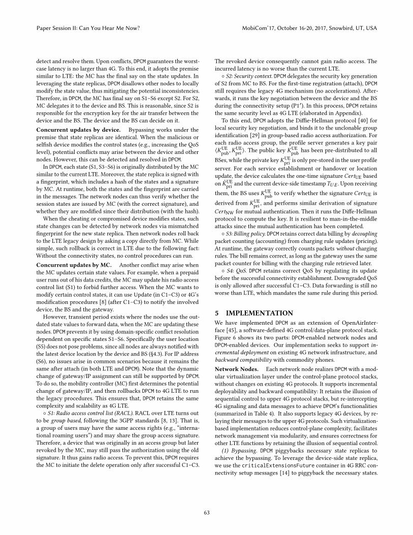
5 IMPLEMENTATIONWe have implemented DPCM as an extension of OpenAirInter-face [45], a software-defined 4G control/data-plane protocol stack.Figure 6 shows its two parts: DPCM-enabled network nodes andDPCM-enabled devices. Our implementation seeks to support in-cremental deployment on existing 4G network infrastructure, andbackward compatibility with commodity phones.Network Nodes. Each network node realizes DPCM with a mod-ular virtualization layer under the control-plane protocol stacks,without changes on existing 4G protocols. It supports incrementaldeployability and backward compatibility: It retains the illusion ofsequential control to upper 4G protocol stacks, but re-intercepting4G signaling and data messages to achieve DPCM’s functionalities(summarized in Table 4). It also supports legacy 4G devices, by re-laying their messages to the upper 4G protocols. Such virtualization-based implementation reduces control-plane complexity, facilitatesnetwork management via modularity, and ensures correctness forother LTE functions by retaining the illusion of sequential control.
(1) Bypassing. DPCM piggybacks necessary state replicas toachieve the bypassing. To leverage the device-side state replica,we use the criticalExtensionsFuture container in 4G RRC con-nectivity setup messages [14] to piggyback the necessary states.
Paper Session II: Can You Hear Me Now? MobiCom’17, October 16-20, 2017, Snowbird, UT, USA
63
4G-LTE stack
DPCM layer4G-LTE stack
DPCM layer
DPCM-extension daemon
4G-LTE stack
4G-LTE stack
4G-LTE stack
In-band messages
Control-data pipelining
Bypasssing
Control proc parallelization
DPCM virtualization layer
Legacy 4G device
DPCM-awaredevice
Data planeControl plane
DPCM layer
Figure 6: DPCM’s system components.
LTE-stack messages DPCM-layer actionP1: Radio conn. setup Relay to LTE stack. Run bypassing with its pig-
gybacked info.P2: Service request Locally acknowledge LTE stack with the state
from the bypassing.P3: Auth. and security Immediately acknowledge LTE stack with local
key agreement and radio access control groupidentification.
P4: Initial context setup Locally acknowledge LTE’s requests. Bypassinghas achieved the same function.
P5: Data bearer setup Relay to LTE stack.P6: Data notification Relay to LTE stack.P7: Paging messages Relay to LTE stack.P8: Modify bearer Locally acknowledge LTE stack. In-band pipelin-
ing has achieved the same function.P9: Radio connectivityreestablishment
Relay to LTE stack. Run bypassing with its pig-gybacked info
P10: Location update Relay to LTE stack.P11: Primary state transfer Locally acknowledge LTE stack. Bypassing and
parallelization have achieved the same function.P12: Bearer update Locally acknowledge LTE stack. In-band pipelin-
ing has achieved the same function.P13: User profile update Relay to LTE stack.
Table 4: DPCM virtualizes 4G control procedures.
These fields are only visible to DPCM layer, and are removed whenthe message is delivered to the upper 4G protocols.
(2) Pipelining Control-Data. We implement DPCM’s in-bandpipelining by overloading the standardized cellular data tunnel(GTP-U [13]). The signaling messages are piggybacked as payloads(together with normal data) of the GTP-U packets. On receipt ofthem, the DPCM layer will extract the signaling messages, push themto acceleration components, and hold the normal data until manda-tory control procedures are completed.
(3) Control-control parallelization. The DPCM layer implementsconcurrent operations to parallelize sequential control proce-dures.The state replica proposed from the device to network nodesis carried within the data-plane (via GTP-U tunnels [13]). The statereplica proposed by network nodes is piggybacked inside the stan-dardized messages from control interfaces (S1-AP [15] between theBS and MC, and GTP-C [7] between the MC and gateways). Oncethe the network nodes install the correct states and resolve thestate conflicts, DPCM locally acknowledges 4G protocols’ pendingprocedures without waiting for legacy state migrations.
(4) Handling conflicts. It is realized as follows.◦ Radio access control (S1) and security (S2). DPCM uses the PBClibrary [1] to implement the group identification for radio accesscontrol, and key negotiation through the Diffe-Hellman protocol.
◦ Data Billing (S3). DPCM retains the correct data billing by decou-pling packet counting from charging rule. The granularity of count-ing packets depends on whether per-flow or per-device billing isapplied (based on pre-purchased data plan). The base station learnsit by checking the device’s charging group (using group identifi-cation). For per-flow billing, the gateway temporarily records theflow ID for every packet.◦QoS (S4). With unclonable group identification above, the gatewaylearns the device’s QoS class, which offers further information onpacket delay/loss/priority. For the non-class QoS metrics, only theminimum QoS (e.g., best-effort service) is offered before sessionstate is migrated. This forwarding under QoS is still no worse than4G: Under the same condition, 4G will not enable any data accessto the device at the same time.Device-side support. To benefit from DPCM, the devices shouldbe upgraded to support it. DPCM can be incrementally deployed as asoftware daemon, without changing the hardware modem. It pre-stores device-side session states in the reserved fields of the SIM card(standardized in [9]). Note that only the critical states S1–S6 shouldbe stored on the client side. To retain the same security level as 4GLTE, these states are associated with the fingerprints (§4.4) storedin the SIM card. It extends the existing device-side state replicafor bypassing control procedures using radio connectivity setup(P1). This is realized with the ENVELOPE commands [10] from OSto SIM card (e.g., via Android Telephony [2]). Then it generatesDPCM-aware in-band messages (§4.1–§4.3). It uses Android’s VPNinterface oip [31] to redirect packets to a separate tunnel at OSlevel, re-encapsulates it with piggybacked device-side states, andthen forward them to the LTE air interface.
6 EVALUATIONWe assess DPCM’s overall latency reduction (§6.1), effectiveness of itscomponents (§6.2), benefits on apps (§6.3) and its overhead (§6.4).Experiment setup. To approximate the operational networks,we deploy DPCM in a testbed, configure it with the parameters ob-served from real-world operational networks and run evaluationexperiments.
The testbed consists of three servers (Dell PowerEdge T320,2.7 GHz 6-core Intel Xeon E5-2420V2 CPU, 8 GB RAM and three1 Gbps Ethernet ports) with the network topology shown in Fig-ure 4c. One server runs the user profile database, while othersemulate two location domains by running multiple machines eachserving as the software-defined BS, gateway and MC separately.Each virtual machine installs Ubuntu 14.04, OpenAirInterface [45]and DPCM. We use oaisim from OpenAirInterface to emulate themobile device and the radio link. We configure the testbed withparameters and round-trips observed from the user study logs overoperational networks (§2). In each log, we retrieve signaling mes-sages and quantify the elapsed time between successive messagesin each control procedure. We then configure the radio latencyin oaisim as the round-trip time of 4G radio connectivity setupprocedure, and the round-trip delay for each procedure in OpenAir-Interface as the breakdown results (using tc command). To assessthe failure handling, we inject the state migration failures betweenthe MC and gateways/BS/profile server, and transient radio linkfailures. Our approximation of radio transmission time might be
Paper Session II: Can You Hear Me Now? MobiCom’17, October 16-20, 2017, Snowbird, UT, USA
64
10
100
1000
10000
C1 C1F C2 C2F C3 C3F
Late
ncy (
ms)
4G LTEDPCM
Figure 7: DPCM’s overall latency reduction.C1 C1F C2 C2F C3 C3F
DPCM (ms)
Avg 80.0 98.2 24.7 89.3 166.2 359.1Min 35.0 47.5 13.7 63.9 41.2 160.095th 112.5 124.3 37.8 135.3 245.0 887.3Max 957.1 146.0 177.5 220.6 2927.0 5546.8
∆ (ms)
Avg 88.7 748.7 0 580.8 735.4 2645.4Min 29.4 483.2 0 153.7 132.0 961.195th 132.7 1026.1 0 1300.0 988.8 6130.7Max 928.3 1081.2 0 1881.2 2887.5 10835.0
η
Avg 2.1× 8.9× 1× 7.8× 5.8× 11.5×Min 1.04× 5.4× 1× 2.5× 1.2× 1.2×95th 3.0× 13.3× 1× 16.7× 7.5× 26.2×Max 16.9× 22.1× 1× 17.5× 13.9× 59.9×
Table 5: Statistics of latency reduction. For each round, ∆ =4G - DPCM, η = 4G/DPCM.
slightly optimistic without taking into account of the time neededfor transferring extra bytes piggybacked (312 byte in §6.4).
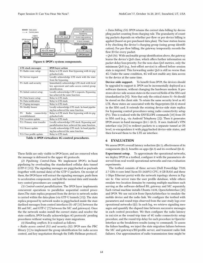
6.1 Overall PerformanceWe examine how much control-plane latency DPCM could reducecompared with 4G LTE. In each round, we configure the test bedwith the parameters and round-trips observed from the operational4G, and compare DPCM with 4G under two metrics: ∆ = 4G − DPCMand η = 4G/DPCM. Figure 7 and Table 5 show the results in all thenormal/failure scenarios in §2–3. We have three observations.
First, DPCM reduces control-plane latency in all the scenariosexcept C2. On average, it reduces latency to 80.0ms (4G: 168.7ms),98.2ms (4G: 846.9ms), 89.3ms (4G: 670.1ms), 166.2ms (4G: 901.6ms),and 359.1ms (4G: 3004.5ms) in C1, C1F, C2F, C3 and C3F, respec-tively. Note that for legacy LTE, all scenarios’ results conform to ourstudies in §2. For each run, we define ∆ as DPCM’s latency reductionover 4G, and η as the ratio of 4G’s latency over DPCM. Table 5 showsthat, the minimal reduction is 29.4ms, 483.2ms, 153.7ms, 132.0msand 961.1ms in C1, C1F, C2F, C3 and C3F. On average, DPCM achieves2.1×, 8.9×, 7.8×, 5.8×, and 11.5× reduction, respectively.
Second, DPCM saves more latency in mobility scenario. On aver-age, DPCM saves 646.7ms more latency in C3 than C1 (no failures).The reason is that, the mobile scenario involves more control proce-dures (Figure 4) and thus more opportunities for latency reduction.
Third, DPCM further reduces latencies by handling failures. La-tency reductions (∆) are more significant in the failure cases (C1F,C2F and C3F). This is because DPCM helps to carry needed states inin-band signaling messages and thus largely avoid further failures.In fact, DPCM is resilient to transient failures and it induces lowlatency in all the cases, regardless of failures or not.
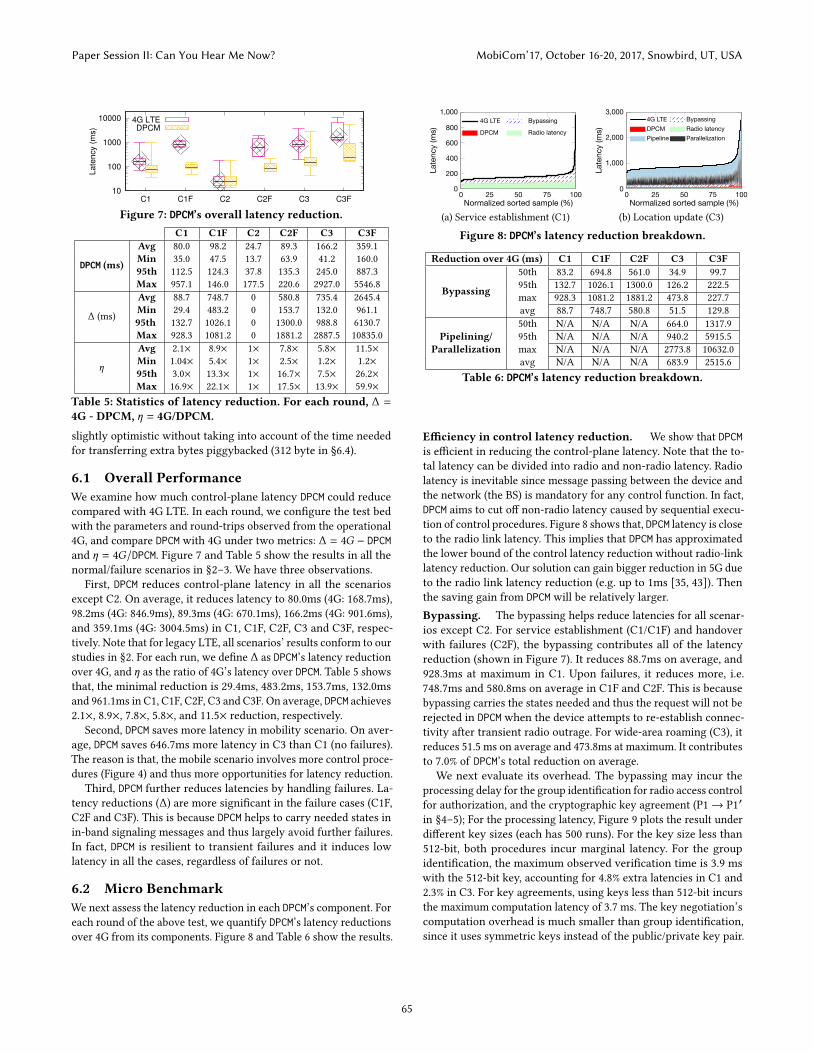
6.2 Micro BenchmarkWe next assess the latency reduction in each DPCM’s component. Foreach round of the above test, we quantify DPCM’s latency reductionsover 4G from its components. Figure 8 and Table 6 show the results.
0 25 50 75 1000
200
400
600
800
1,000
Normalized sorted sample (%)
Late
ncy
(ms)
4G LTE Bypassing
DPCM Radio latency
(a) Service establishment (C1)
0 25 50 75 1000
1,000
2,000
3,000
Normalized sorted sample (%)
Late
ncy
(ms)
4G LTE BypassingDPCM Radio latencyPipeline Parallelization
(b) Location update (C3)
Figure 8: DPCM’s latency reduction breakdown.
Reduction over 4G (ms) C1 C1F C2F C3 C3F
Bypassing
50th 83.2 694.8 561.0 34.9 99.795th 132.7 1026.1 1300.0 126.2 222.5max 928.3 1081.2 1881.2 473.8 227.7avg 88.7 748.7 580.8 51.5 129.850th N/A N/A N/A 664.0 1317.9
Pipelining/ 95th N/A N/A N/A 940.2 5915.5Parallelization max N/A N/A N/A 2773.8 10632.0
avg N/A N/A N/A 683.9 2515.6Table 6: DPCM’s latency reduction breakdown.
Efficiency in control latency reduction. We show that DPCMis efficient in reducing the control-plane latency. Note that the to-tal latency can be divided into radio and non-radio latency. Radiolatency is inevitable since message passing between the device andthe network (the BS) is mandatory for any control function. In fact,DPCM aims to cut off non-radio latency caused by sequential execu-tion of control procedures. Figure 8 shows that, DPCM latency is closeto the radio link latency. This implies that DPCM has approximatedthe lower bound of the control latency reduction without radio-linklatency reduction. Our solution can gain bigger reduction in 5G dueto the radio link latency reduction (e.g. up to 1ms [35, 43]). Thenthe saving gain from DPCM will be relatively larger.Bypassing. The bypassing helps reduce latencies for all scenar-ios except C2. For service establishment (C1/C1F) and handoverwith failures (C2F), the bypassing contributes all of the latencyreduction (shown in Figure 7). It reduces 88.7ms on average, and928.3ms at maximum in C1. Upon failures, it reduces more, i.e.748.7ms and 580.8ms on average in C1F and C2F. This is becausebypassing carries the states needed and thus the request will not berejected in DPCM when the device attempts to re-establish connec-tivity after transient radio outrage. For wide-area roaming (C3), itreduces 51.5 ms on average and 473.8ms at maximum. It contributesto 7.0% of DPCM’s total reduction on average.
We next evaluate its overhead. The bypassing may incur theprocessing delay for the group identification for radio access controlfor authorization, and the cryptographic key agreement (P1 → P1′in §4–5); For the processing latency, Figure 9 plots the result underdifferent key sizes (each has 500 runs). For the key size less than512-bit, both procedures incur marginal latency. For the groupidentification, the maximum observed verification time is 3.9 mswith the 512-bit key, accounting for 4.8% extra latencies in C1 and2.3% in C3. For key agreements, using keys less than 512-bit incursthe maximum computation latency of 3.7 ms. The key negotiation’scomputation overhead is much smaller than group identification,since it uses symmetric keys instead of the public/private key pair.
Paper Session II: Can You Hear Me Now? MobiCom’17, October 16-20, 2017, Snowbird, UT, USA
65
128-bitkey
256-bitkey
512-bitkey
1024-bitkey
2048-bitkey
050
100150
Latenc
y(m
s) Unclonable group identification for RACL (S1)
Security key agreement (S2)
Figure 9: DPCM’s bypassing’s extra processing latency vs. cryp-tographical key size.
0 2 4 6 8 100
20
40
60
80
100
Web loading (s)
CDF
(%)
DPCM4G w/o failure4G w/ failure
(a) Web
0 5 10 15 20 25 300
20
40
60
80
100
YouTube pause (s)
CDF
(%)
DPCM4G w/o failure4G w/ failure
(b) YouTubeFigure 10: Web/YouTube latency improvements in DPCM.
Pipelining and parallelization. DPCM’s pipelining and paral-lelization help reduce latencies in wide-area roaming (C3/C3F).While not applicable to C1 and C2, they are critical componentsfor wide-area roaming. In failure-free case (C3), the pipelining andparallelization reduce 683.9 ms on average and 2.7 s at maximum.They contribute 93.0% of DPCM’s total latency reduction on average.With failures (C3F), they reduce 2.5s latency and contribute 95.1%reduction on average. The reason is that, the wide-area roaminginvolves more control procedures among more network nodes. Thisoffers more room for DPCM to reduce the latency.
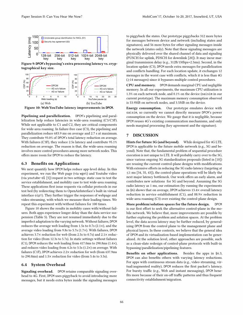
6.3 Benefits on ApplicationsWe next quantify how DPCM helps reduce app-level delay. In thisexperiment, we run the Web page (via wget) and Youtube video(via youtube-dl [5]) request in two settings: static case to test theservice establishment, and mobility case to test wide-area roaming.These applications first issue requests via cellular protocols in ourtest bed (by redirecting them to OpenAirInterface’s built-in virtualinterface oip1). They further trigger the responses of webpage andvideo streaming, with which we measure their loading times. Werepeat this experiment with/without failures for 100 times.
Figure 10 shows the results in mobility cases with/without fail-ures. Both apps experience longer delay than the data service sus-pension (Table 5). They are not resumed immediately due to theimperfect adaptation to the varying network.Without failures, DPCMreduces the average web loading from 1.5s to 0.7s (2.1×), and theaverage video loading from 9.8s to 5.7s (1.7×). With failures, DPCMachieves 3.7× reduction for web (from 2.5s to 0.7s) and 2.1× reduc-tion for video (from 12.3s to 5.7s). In static settings without failures(C1), DPCM reduces the web loading from 417.0ms to 290.8ms (1.4×),and reduces video loading from 4.2s to 3.5s (1.2×) on average. Withfailures (C1F), DPCM achieves 2.2× reduction for web (from 637.9msto 290.8ms) and 1.5× reduction for video (from 5.4s to 3.5s).
6.4 System OverheadSignaling overhead. DPCM retains comparable signaling over-head to 4G. First, DPCM uses piggyback to avoid introducing moremessages, but it needs extra bytes inside the signaling messages
to piggyback the states. Our prototype piggybacks 312 more bytesfor messages between device and network (including states andsignatures), and 56 more bytes for other signaling messages insidethe network (states only). Note that these signaling messages arephysically delivered over the shared channel of data and signaling(PUSCH for uplink, PDSCH for downlink [20]). It may incur mar-ginal transmission delay (e.g., 312B/1Mbps=2.5ms). Second, in thelocation update (C3), DPCM needs extra messages for parallelizationand conflicts handling. For each location update, it exchanges 12messages in the worst case with conflicts, which it is less than 4G(≥14 messages) since it bypasses multiple control procedures.CPU andmemory. DPCM demands marginal CPU and negligiblememory. In all our experiments, the maximum CPU utilization is1.3% on each network node, and 0.1% on the device (oaisim in ourcurrent prototype). The maximum memory consumption observedis 53.9MB on network nodes, and 3.5MB on the device.Energy consumption. Our prototype emulates device withoaisim, so currently we cannot directly measure DPCM’s powerconsumption on the device. We gauge that it is negligible, becauseDPCM reuses 4G’s existing communication mechanisms, and onlyneeds marginal processing (key agreement and the signature).
7 DISCUSSIONHints for future 5G (and beyond). While designed for 4G LTE,DPCM is applicable to the future mobile network (e.g., 5G and be-yond). Note that, the fundamental problem of sequential procedureexecution is not unique to LTE. It will probably carry over to the 5G,since various ongoing 5G standardization proposals (listed in [18])are reusing the current control-plane designs with modifications.With extensive efforts in reducing the 5G radio latency (targeting at≤1 ms [34, 35, 43]), the control-plane operations will be likely thenext major latency bottleneck. Our work offers an early alarm, andcontributes new solutions for 5G and beyond. Assuming the 5Gradio latency as 1 ms, our estimation (by running the experimentsin §6) shows that on average, DPCM achieves 13.4× overall latencyreduction in service establishment (C1), and 88.9× reduction inwide-area roaming (C3) over existing the control-plane design.More problem/solution spaces for the future design. DPCMis our first effort to seek the alternative control-plane in the mo-bile network. We believe that, more improvements are possible byfurther exploring the problem and solution spaces. At the problemlevel, the data access latency may be further reduced, by general-izing DPCM from the control plane to the management plane andphysical layers. In these contexts, we believe that the general ideaof DPCM and its virtualization-based implementation can be gener-alized. At the solution level, other approaches are possible, suchas a clean-slate redesign of control-plane protocols with built-inbypassing/parallelization/pipelining features.Benefits on other applications. Besides the apps in §6.3,DPCM can also benefits others with varying latency reductions.For apps with continuous stream data (e.g., video streaming, vir-tual/augmented reality), DPCM reduces the first packet’s latency.For bursty traffic (e.g., Web and instant messaging), DPCM bene-fits more because of their on-off traffic patterns and thus frequentconnectivity establishment/migration.
Paper Session II: Can You Hear Me Now? MobiCom’17, October 16-20, 2017, Snowbird, UT, USA
66
8 RELATEDWORKIn recent years, extensive efforts have beenmade to improve the per-formance of 4G LTE networks. They include improving the wirelessaccess [25, 53, 57] and management [33, 60], cross-layer optimiza-tion of transport protocols [44, 61, 65] and apps [24, 26, 62, 63]to name a few. We study a different topic of how control-planeoperations affect data access latency. At the control plane, severaloptimizations for specific control procedures (notably fast hand-offs) are proposed, including the pre-tunneling [41, 64], mitigat-ing the authentication time [22, 32, 55], modifying the signalingmessages [28, 66], parameter tunings[21, 49, 50], etc. DPCM differsfrom them, since it studies a broader set of control procedures,and parallelizes them for low data access latency. Several recentefforts seek to simplify the cellular infrastructure using software-defined [36, 42, 58] and virtualization [27, 46, 47] approaches. Ourwork differs from them in two dimensions. First, we focus on aunique issue of latency deficiency (i.e. the sequential control). Sec-ond, DPCM leverages the client-side state replica to latency reduction,which has not been explored by prior efforts.
There have been several recent studies on the Internet controlplane [30, 37, 39, 51, 56], in the context of software-defined network-ing. They examine how to perform consistent state update [39, 51],state migration in middle-boxes [30, 37, 54], and conflict resolutionover shared states [56], etc. Instead, we study how to accelerate 4Gcontrol-plane operations, which are much more complex than theirInternet counterpart.
9 CONCLUSIONIt has become increasingly important to offer always-on, low-latency network service to the mobile users. In this work, we showthat current LTE control-plane operations create a major bottleneckfor reducing latency for mobile data access. On one hand, they arewell justified since they provision necessary states at the device andnetwork nodes to start or retain data service. On the other hand,their design does not account for efficient operations in the 4G/5Gera. In fact, they are required to run sequentially and have to be allcompleted before starting/resuming data-plane packet delivery. Inthis work, we analyze their latency root causes and apply parallelcomputing techniques to speed it up.
Our work can be understood in a broader context. Like otherdistributed systems, LTE network should balance the latency andconsistency in its control-plane operations. This problem is largelyunaddressed, and leads to large delay at the user side. While thecommunity has made extensive efforts on improving data-planewireless access, issues on the control-plane have been overlookedto certain extent. On the solution side, our initial attempt to accel-erate the control functions yields promising results. Our study maystimulate more community interests on applying the rich insightsfrom distributed system context to revamp the 4G/5G design.
APPENDIX: SECURITY ANALYSISWe show how DPCM retains the same security level as 4G LTE. Thisnails down to three goals: (1) for threats that can be defended by 4G(specified in standards [16, 17]), DPCM should also defend it; (2) forthreats that cannot be defended by 4G (e.g., DoS), DPCM should notfurther ease or amplify them; (3) new threats should not be made
possible by DPCM itself. We next analyze how DPCM satisfies themby exploring the possible attacks.Authentication/authorization/accounting. DPCM offers mu-tual authentication and authorization with Diffe-Hellman protocolbound with group identification (§4.4), and correct accounting bydecoupling packet counting from policy updates.Over-the-air confidentiality and integrity. DPCM encryptsuser’s data and signaling over the air. It replaces 4G’s key agree-ments with a variant of Diffe-Hellman protocol (§4.4).Defenses to man-in-the-middle attacks. Two threats exist.The first is the IMSI catcher, which fakes the base station and sniffsthe device behaviors. DPCM defenses this withmutual authentication,and encrypts user data and signaling over the air. The second is theDiffe-Hellman protocol for key agreement, whose original versioncan be exploited to fake the negotiated keys in the middle. DPCMdefends it by binding the key agreement after the group-basedauthentication, thus detecting the faked device or network nodes.Denial-of-service attacks. 4G LTE is vulnerable to DoS attacksby design. Previousworks [23, 48, 59] have shown that, themaliciousdevices can exploit the radio resource scheduling and signalingmessages, and launch radio jamming and DDoS attacks to basestations and mobility controllers. The 4G standards [16, 17] choosenot to fully address DoS because of the high cost. Similar attacks canalso appear in DPCM, which however does not ease or amplify them.With piggyback mechanisms, DPCM does not incur more signalingmessages between device and network than 4G LTE.Local device attacks. This is a new potential threat in DPCM.Since DPCM leverages device-side information, a selfish device maymodify its local states and affect the control procedures for its ownbenefit (e.g. increase its QoS level). To defend it, DPCM lets networknodes detect the device’s state modification (which is disallowed inDPCM). Once the modification is detected, DPCM rolls back to 4G’snetwork-only control procedures, which guarantees the same 4Gsecurity level. Note that, the device-side states are initialized anddistributed by the MC during the session state/migration. In DPCM,the state is distributed together with a fingerprint issued by thenetwork nodes for integrity verification. The fingerprint includes ahash of the session states, and a signature issued by the mobilitycontroller using the group identification key. At runtime, the deviceshould carry the states and the fingerprint in the in-band messages.Then the network nodes can verify whether the session state isissued by the mobility controller (with the signature), and whetherthe states are modified since distribution (with the hash).
Acknowledgments: We greatly appreciate our shepherd, Dr.Eric Rozner, and the anonymous reviewers for their constructivecomments. This work at its early stage was partially supported byNSF Grants: CNS-1526985, CNS-1526456, CNS-1423576 and CNS-1421440.
REFERENCES[1] 2013. PBC Library. https://crypto.stanford.edu/pbc/. (2013).[2] 2017. Android TelephonyManager class. http://developer.android.com/reference/
android/telephony/TelephonyManager.html. (2017).[3] 2017. MobileInsight. http://www.mobileinsight.net. (2017).[4] 2017. OpenAirInterface project. https://gitlab.eurecom.fr/oai/openairinterface5g/
wikis/home. (2017).[5] 2017. Youtube-dl library. (2017). https://rg3.github.io/youtube-dl/.
Paper Session II: Can You Hear Me Now? MobiCom’17, October 16-20, 2017, Snowbird, UT, USA
67
[6] 3GPP. 2006. TS25.331: Radio Resource Control (RRC). (2006). http://www.3gpp.org/ftp/Specs/html-info/25331.htm
[7] 3GPP. 2012. TS29.274: 3GPP Evolved Packet System (EPS); Evolved GeneralPacket Radio Service Tunneling Protocol for Control plane (GTPv2-C); Stage 3.(Sep. 2012). http://www.3gpp.org/DynaReport/29274.htm
[8] 3GPP. 2013. TS24.301: Non-Access-Stratum (NAS) for EPS; . (Jun. 2013). http://www.3gpp.org/ftp/Specs/html-info/24301.htm
[9] 3GPP. 2013. TS31.102: Characteristics of the Universal Subscriber Identity Module(USIM) application. (Sep. 2013). http://www.3gpp.org/DynaReport/31102.htm
[10] 3GPP. 2014. TS31.111: Universal Subscriber Identity Module (USIM); ApplicationToolkit (USAT). (Dec. 2014). http://www.3gpp.org/DynaReport/31111.htm
[11] 3GPP. 2015. TS23.401: General Packet Radio Service enhancements for EvolvedUniversal Terrestrial Radio Access Network (E-UTRAN) access. (Dec. 2015).http://www.3gpp.org/ftp/Specs/html-info/23401.htm
[12] 3GPP. 2015. TS29.272: Mobility Management Entity and and Serving GPRSSupport Node related interfaces based on Diameter protocol. (Mar. 2015). http://www.3gpp.org/ftp/Specs/html-info/36331.htm
[13] 3GPP. 2015. TS29.281: 3GPP Evolved Packet System (EPS); Evolved GeneralPacket Radio Service Tunneling Protocol for User Plane (GTPv1-U); Stage 3. (Sep.2015). http://www.3gpp.org/DynaReport/29281.htm
[14] 3GPP. 2015. TS36.331: Radio Resource Control (RRC). (Mar. 2015). http://www.3gpp.org/ftp/Specs/html-info/36331.htm
[15] 3GPP. 2015. TS36.413: S1 Application Protocol (S1AP). (Jun. 2015). http://www.3gpp.org/ftp/Specs/html-info/36413.htm
[16] 3GPP. 2016. TS33.401: 3GPP System Architecture Evolution (SAE); Securityarchitecture. (2016).
[17] 3GPP. 2016. TS33.401: Service requirements for the Evolved Packet System (EPS).(Jun. 2016).
[18] 3GPP. 2017. 3GPP 5G New Radio Working Group: Radio Interface architectureand protocols. (2017). http://www.3gpp.org/Specifications-groups/ran-plenary/46-ran2-radio-layer-2-and-radio-layer
[19] 3GPP. 2017. TS33.203: 3G security; Access security for IP-based services. (2017).[20] 3GPP. 2017. TS36.211: Evolved Universal Terrestrial Radio Access (E-UTRA);
Physical channels and modulation. (2017).[21] Yair Amir, Claudiu Danilov, Michael Hilsdale, Raluca Musaloiu-Elefteri, and Nilo
Rivera. 2006. Fast handoff for seamless wireless mesh networks. In Proceedingsof the 4th international conference on Mobile systems, applications and services.ACM.
[22] Mortaza S Bargh, RJ Hulsebosch, EH Eertink, A Prasad, Hu Wang, and PeterSchoo. 2004. Fast authentication methods for handovers between IEEE 802.11wireless LANs. In Proceedings of the 2nd ACM international workshop on Wirelessmobile applications and services on WLAN hotspots. ACM, 51–60.
[23] Ramzi Bassil, Ali Chehab, Imad Elhajj, andAymanKayssi. 2012. Signaling orienteddenial of service on LTE networks. In Proceedings of the 10th ACM internationalsymposium on Mobility management and wireless access. ACM, 153–158.
[24] Kevin Boos, David Chu, and Eduardo Cuervo. 2016. Flashback: Immersive virtualreality on mobile devices via rendering memoization. In Proceedings of the 14thAnnual International Conference on Mobile Systems, Applications, and Services.ACM, 291–304.
[25] Eugene Chai, Karthik Sundaresan, Mohammad A Khojastepour, and SampathRangarajan. 2016. LTE in unlicensed spectrum: are we there yet?. In Proceedingsof the 22nd Annual International Conference on Mobile Computing and Networking.ACM, 135–148.
[26] Abhijnan Chakraborty, Vishnu Navda, Venkata N Padmanabhan, and Ramachan-dran Ramjee. 2013. Coordinating cellular background transfers using loadsense.In The 19th Annual International Conference on Mobile Computing and Networking(MobiCom). ACM, 63–74.
[27] Junguk Cho, Karthikeyan Sundaresan, Rajesh Mahindra, Jacobus Van der Merwe,and Sampath Rangarajan. 2016. ACACIA: Context-aware Edge Computing forContinuous Interactive Applications over Mobile Networks. In Proceedings ofthe 12th International on Conference on emerging Networking EXperiments andTechnologies. ACM, 375–389.
[28] Mostafa Zaman Chowdhury, Won Ryu, Eunjun Rhee, and Yeong Min Jang. 2009.Handover between Macrocell and Femtocell for UMTS Based Networks. In IEEEICACT.
[29] Ivan Damgård, Kasper Dupont, and Michael Østergaard Pedersen. 2006. Un-clonable group identification. In Advances in Cryptology-EUROCRYPT. Vol. 4004.Springer, 555–572.
[30] Aaron Gember-Jacobson, Raajay Viswanathan, Chaithan Prakash, Robert Grandl,Junaid Khalid, Sourav Das, and Aditya Akella. 2015. OpenNF: Enabling innovationin network function control. ACM SIGCOMM Computer Communication Review44, 4 (2015), 163–174.
[31] Google. 2017. VpnService. https://developer.android.com/reference/android/net/VpnService.html. (2017).
[32] Robert Hsieh, Zhe Guang Zhou, and Aruna Seneviratne. 2003. S-MIP: A seamlesshandoff architecture for mobile IP. In INFOCOM 2003. Twenty-Second AnnualJoint Conference of the IEEE Computer and Communications. IEEE.
[33] Junxian Huang, Feng Qian, ZMorleyMao, Subhabrata Sen, and Oliver Spatscheck.2014. RadioProphet: Intelligent radio resource deallocation for cellular networks.In Passive and Active Measurement. Springer, 1–11.
[34] Huawei. 2013. 5G: A Technology Vision. http://www.huawei.com/5gwhitepaper/.(2013).
[35] GSMA Intelligence. 2014. Understanding 5G: Perspectives on future technologicaladvancements in mobile. https://www.gsmaintelligence.com/research/?file=141208-5g.pdf&download. (Dec. 2014).
[36] Xin Jin, Li Erran Li, Laurent Vanbever, and Jennifer Rexford. 2013. SoftCell:scalable and flexible cellular core network architecture. In CoNEXT 2013.
[37] Junaid Khalid, Aaron Gember-Jacobson, Roney Michael, Anubhavnidhi Ab-hashkumar, and Aditya Akella. 2016. Paving the Way for NFV: SimplifyingMiddlebox Modifications using StateAlyzr. In 13th USENIX Symposium on Net-worked Systems Design and Implementation (NSDI 16). 239–253.
[38] Yuanjie Li, Chunyi Peng, Zengwen Yuan, Jiayao Li, Haotian Deng, and Tao Wang.[n. d.]. Mobileinsight: Extracting and Analyzing Cellular Network Informationon Smartphones. In Proceedings of the 22nd Annual International Conference onMobile Computing and Networking (MobiCom ’16). ACM.
[39] Hongqiang Harry Liu, Xin Wu, Ming Zhang, Lihua Yuan, Roger Wattenhofer,and David Maltz. 2013. zUpdate: Updating data center networks with zero loss.ACM SIGCOMM Computer Communication Review 43, 4 (2013), 411–422.
[40] Ralph C Merkle. 1978. Secure communications over insecure channels. Commun.ACM 21, 4 (1978), 294–299.
[41] Shantidev Mohanty and Ian F Akyildiz. 2006. A cross-layer (layer 2+ 3) handoffmanagement protocol for next-generation wireless systems. IEEE Transactionson Mobile Computing 5, 10 (2006), 1347–1360.
[42] Mehrdad Moradi, Wenfei Wu, Li Erran Li, and Z. Morley Mao. 2014. SoftMoW:A Dynamic and Scalable Software Defined Architecture for Cellular WANs. InACM CoNext.
[43] NGMN. 2015. NGMN 5G white paper. https://www.ngmn.org/uploads/media/NGMN_5G_White_Paper_V1_0.pdf. (2015).
[44] Binh Nguyen, Arijit Banerjee, Vijay Gopalakrishnan, Sneha Kasera, SeungjoonLee, Aman Shaikh, and Jacobus Van der Merwe. 2014. Towards Understand-ing TCP Performance on LTE/EPC Mobile Networks. In Proceedings of the 4thWorkshop on All Things Cellular: Operations, Applications, and Challenges (AllTh-ingsCellular’14). ACM.
[45] Navid Nikaein, Mahesh K Marina, Saravana Manickam, Alex Dawson, RaymondKnopp, and Christian Bonnet. 2014. OpenAirInterface: A Flexible Platform for 5GResearch. ACM SIGCOMM Computer Communication Review 44, 5 (2014), 33–38.
[46] Shoumik Palkar, Chang Lan, Sangjin Han, Keon Jang, Aurojit Panda, SylviaRatnasamy, Luigi Rizzo, and Scott Shenker. 2015. E2: a framework for NFVapplications. In Proceedings of the 25th Symposium on Operating Systems Principles.ACM, 121–136.
[47] Zafar Qazi, Melvin Walls, Aurojit Panda, Vyas Sekar, Sylvia Ratnasamy, and ScottShenker. 2017. A High Performance Packet Core for Next Generation CellularNetworks. In Proceedings of the 2017 ACM Conference on Special Interest Group onData Communication (SIGCOMM’17). ACM.
[48] Radmilo Racic, Denys Ma, Hao Chen, and Xin Liu. 2008. Exploiting OpportunisticScheduling in Cellular Data Networks. In NDSS 2008.
[49] Ishwar Ramani and Stefan Savage. 2005. SyncScan: practical fast handoff for802.11 infrastructure networks. In Proceedings IEEE 24th Annual Joint Conferenceof the IEEE Computer and Communications Societies., Vol. 1. IEEE, 675–684.
[50] Ayaskant Rath and Shivendra Panwar. 2012. Fast handover in cellular networkswith femtocells. In Communications (ICC), 2012 IEEE International Conference on.IEEE, 2752–2757.
[51] Mark Reitblatt, Nate Foster, Jennifer Rexford, Cole Schlesinger, and David Walker.2012. Abstractions for network update. In Proceedings of the ACM SIGCOMM 2012conference on Applications, technologies, architectures, and protocols for computercommunication (SIGCOMM). ACM, 323–334.
[52] Sanae Rosen, Haokun Luo, Qi Alfred Chen, Z Morley Mao, Jie Hui, Aaron Drake,and Kevin Lau. 2014. Discovering fine-grained RRC state dynamics and perfor-mance impacts in cellular networks. In The 20th Annual International Conferenceon Mobile Computing and Networking (MobiCom’14). ACM.
[53] Paul Schmitt, Daniel Iland, Mariya Zheleva, and Elizabeth Belding. 2016. Hy-bridCell: Cellular connectivity on the fringes with demand-driven local cells. InComputer Communications, IEEE INFOCOM 2016-The 35th Annual IEEE Interna-tional Conference on. IEEE, 1–9.
[54] Justine Sherry, Peter Xiang Gao, Soumya Basu, Aurojit Panda, Arvind Krishna-murthy, Christian Maciocco, Maziar Manesh, João Martins, Sylvia Ratnasamy,and Luigi Rizzo. 2015. Rollback-Recovery for Middleboxes. In Proceedings of the2015 ACM Conference on Special Interest Group on Data Communication. ACM,227–240.
[55] H. Soliman, C. Castelluccia, K. ElMalki, and L. Bellier. 1999. Hierarchical MobileIPv6 (HMIPv6) Mobility Management. (1999). RFC 5380.
[56] Peng Sun, Ratul Mahajan, Jennifer Rexford, Lihua Yuan, Ming Zhang, and AhsanArefin. 2015. A network-state management service. ACM SIGCOMM ComputerCommunication Review 44, 4 (2015), 563–574.
Paper Session II: Can You Hear Me Now? MobiCom’17, October 16-20, 2017, Snowbird, UT, USA
68
[57] Sanjib Sur, Xinyu Zhang, Parmesh Ramanathan, and Ranveer Chandra. 2016.BeamSpy: enabling robust 60 GHz links under blockage. In 13th USENIX Sym-posium on Networked Systems Design and Implementation (NSDI 16). USENIXAssociation, 193–206.
[58] Aisha Syed and Jacobus Van der Merwe. 2016. Proteus: a network service controlplatform for service evolution in a mobile software defined infrastructure. InProceedings of the 22nd Annual International Conference on Mobile Computing andNetworking. ACM, 257–270.
[59] Patrick Traynor, Michael Lin, Machigar Ongtang, Vikhyath Rao, Trent Jaeger,Patrick McDaniel, and Thomas La Porta. 2009. On cellular botnets: measuringthe impact of malicious devices on a cellular network core. In Proceedings of the16th ACM conference on Computer and communications security. ACM, 223–234.
[60] Deepak Vasisht, Swarun Kumar, Hariharan Rahul, and Dina Katabi. 2016. Elimi-nating Channel Feedback in Next-Generation Cellular Networks. In Proceedingsof the 2016 conference on ACM SIGCOMM 2016 Conference. ACM, 398–411.
[61] Keith Winstein, Anirudh Sivaraman, Hari Balakrishnan, et al. 2013. StochasticForecasts Achieve High Throughput and Low Delay over Cellular Networks..In Proceedings of the 10th USENIX conference on Networked Systems Design andImplementation (NSDI). 459–471.
[62] Xiufeng Xie, Xinyu Zhang, Swarun Kumar, and Li Erran Li. 2015. piStream:Physical Layer Informed Adaptive Video Streaming Over LTE. In The 21st AnnualInternational Conference on Mobile Computing and Networking (MobiCom). ACM,413–425.
[63] Xiufeng Xie, Xinyu Zhang, and Shilin Zhu. 2017. Accelerating Mobile WebLoading Using Cellular Link Information. In In ACM International Conference onMobile Systems, Applications, and Services (MobiSys’17). ACM.
[64] Hidetoshi Yokota, Akira Idoue, Toru Hasegawa, and Toshihiko Kato. 2002. Linklayer assisted mobile IP fast handoff method over wireless LAN networks. InProceedings of the 8th annual international conference on Mobile computing andnetworking. ACM, 131–139.
[65] Yasir Zaki, Thomas Pötsch, Jay Chen, Lakshminarayanan Subramanian, andCarmelita Görg. 2015. Adaptive Congestion Control for Unpredictable CellularNetworks. In Proceedings of the 2015 ACM Conference on Special Interest Group onData Communication (SIGCOMM’15). ACM, 509–522.
[66] Haijun Zhang, Xiangming Wen, Bo Wang, Wei Zheng, and Yong Sun. 2010. Anovel handover mechanism between femtocell and macrocell for LTE basednetworks. In Communication Software and Networks, 2010. ICCSN’10.
Paper Session II: Can You Hear Me Now? MobiCom’17, October 16-20, 2017, Snowbird, UT, USA
69