Embed Size (px)
Citation preview
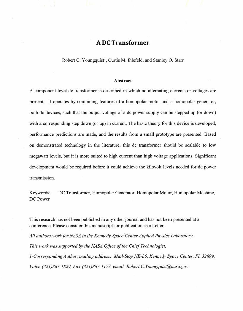
A DC Transformer
Robert C. Youngquist1, Curtis M. Ihlefeld, and Stanley 0 . Starr
Abstract
A component level de transformer is described in which no alternating currents or voltages are
present. It operates by combining features of a homopolar motor and a homopolar generator,
both de devices, such that the output voltage of a de power supply can be stepped up (or down)
with a corresponding step down (or up) in current. The basic theory for this device is developed,
performance predictions are made, and the results from a small prototype are presented. Based
on demonstrated technology in the literature, this de transformer should be scalable to low
megawatt levels, but it is more suited to high current than high voltage applications. Significant
development would be required before it could achieve the kilovolt levels needed for de power
transmission.
Keywords: DC Transformer, Homopolar Generator, Homopolar Motor, Homopolar Machine, DC Power
This research has not been published in any other journal and has not been presented at a conference. Please consider this manuscript for publication as a Letter.
All authors work for NASA in the Kennedy Space Center Applied Physics Laboratory.
This work was supported by the NASA Office of the ChiefTechnologist.
]-Corresponding Author, mailing address: Mail-Stop NE-L5, Kennedy Space Center, Fl. 32899.
Voice-(321)867-1829, Fax-(321)867-1177, email- [email protected]
A DC Transformer
Introduction
This letter presents an electro-mechanical component that transforms de power, allowing de
v·oltages or currents to be stepped up or down. This de transformer is a fundamental element,
comparable to an ac transformer; it does not use internal electrical components, does not rely on
switching or commutation, and does not require additional power to operate. As the theory
section will show, this device is a de counterpart to the well known ac transformer.
DC transformers are commonly referenced in the literature as being synonymous with de
converters [1,2,3,4] , utilizing internal switching to create an ac waveform that can be stepped up
or down with inductors or an ac transformer, and then switched back to a new de voltage. Yet,
this nomenclature is relatively new. A generation ago de transformers were regarded as a
fundamental component, with no internal elements, and were considered to be fictional until a
superconducting version appeared [5] in the 1960s. In this letter a true component level de
transformer is presented, not a de converter.
The device presented here is based on a combination of principles exhibited by hornopolar
motors [6,7] and homopolar generators [8,9]. The underlying idea does not appear to be in the
recent literature however a patent was found describing a "homopolar transformer" [ 1 0] , which
appears to be related to the present concept, although no analysis or results are given in the
patent and the design is more intricate than that developed below. Consequently, the authors
believe that the de transformer described in this letter is worth consideration not only for its
novelty, but for possible further development. There is a need for high power de transformers
[ 1 ,2] and this device should be capable of handling megawatt de power levels by extending
engineering already developed for homopolar motors and generators.
Theory
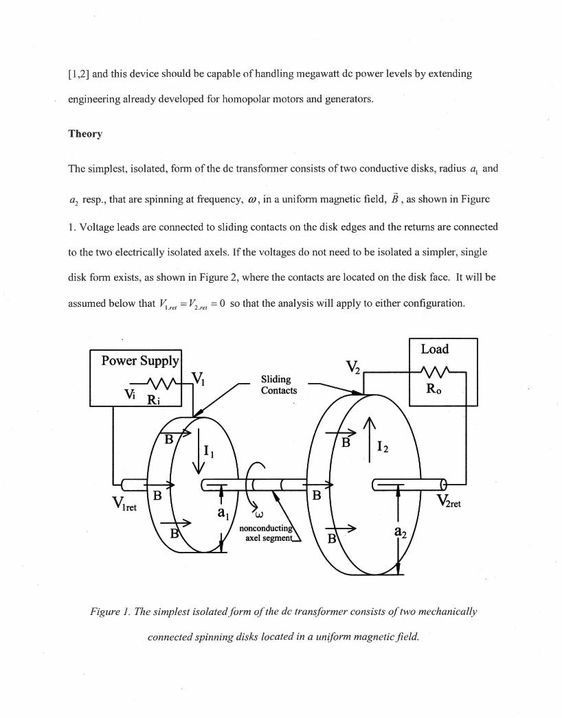
The simplest, isolated, form of the de transfonner consists of two conductive disks, radius a1 and
a2 resp., that are spinning at frequency, m, in a uniform magnetic field, B, as shown in Figure
1. Voltage leads are connected to sliding contacts on the disk edges and the returns are connected
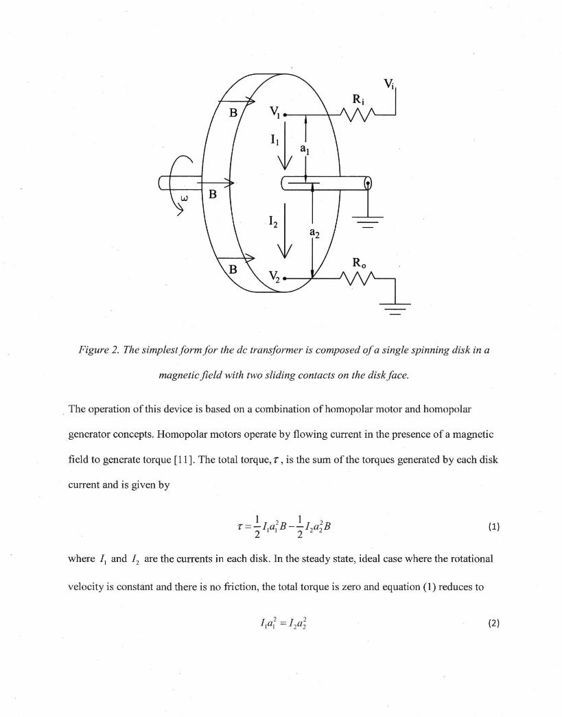
to the two electrically isolated axels. If the voltages do not need to be isolated a simpler, single
disk form exists, as shown in Figure 2, where the contacts are located on the disk face. It will be
assumed below that ~ . ret = V2.ret = 0 so that the analysis will apply to either configuration.
Load Power Supply
~ ,.....----+--Sliding Contacts Ro
Figure 1. The simplest isolatedform of the de transformer consists of two mechanically
connected spinning disks located in a un(form magneticfield.
\'i
v;
'i a I
B
'21 a2
Figure 2. The simplestform for the de transformer is composed of a single spinning disk in a
magnetic field with two sliding contacts on the disk face .
. The operation of this device is based on a combination ofhomopolar motor and homopolar
generator concepts. Homopolar motors operate by flowing current in the presence of a magnetic
field to generate torque [ 11]. The total torque, r, is the sum ofthe torques generated by each disk
current and is given by
{1)
where / 1 and / 2 are the currents in each disk. In the steady state, ideal case where the rotational
velocity is constant and there is no friction, the total torque is zero and equation (1) reduces to
{2)
showing that the disk radii scale the current ratios similar to the coil winding number in an ac
transformer.
Homopolar generators 9perate by rotating a conductor in a magnetic field to generate a voltage,
i.e. a back emf [II]. In the configurations shown in Figure 1 and 2 voltages, v; and V2
respectively, are generated at the disk radii , a1 and a2 according to
and 1 j
V2 = - OJai_B 2
{3)
where OJ is the rotational velocity of the two disk system. The last relation in equation (3) shows
how the disk radii scale the ratio of the voltages on the two disks. Combining equations (2) and
(3) yields the fundamental equation for the operation of an ideal de transformer;
{4)
which is the same power conservation relationship produced when analyzing an ideal ac
transformer. In addition, like an ac transducer, the input and output connections can be
interchanged turning, for example, a voltage step up device into a voltage step down device.
The figures show a power supply with voltage, V; , impedance, R;, and a load Ro . One purpose
of a transformer is to match load impedance to power supply impedance in order to maximize
power delivery. In the case of the de transformer shown in Figure 1 the power supply sees an
impedance given by v; I 11, which can be rewritten as
showing the significant role that the disk radii play in converting the load impedance.
The analysis above can be generalized to include friction by the addition of a frictional torque,
T.r, acting to decelerate the disks yielding a modified version of equation ( 1)
_,
(5)
Making the steady state assumption, where the total torque is set equal to zero, this expression
can be simplified significantly by the incorporation of a frictional current, lr defined by
Ir = 2T1 I (a~ B). This allows equation (5) to be rewritten as
and permits the rest of the analysis to proceed as above yielding ~11. 1 = V2J2 • Physically this
states that friction requires a current penalty, but after paying this the device operates ideally.
Note that the frictional torque and the frictional current are not necessarily constant, for example,
they can vary with rotational speed in the case of air resistance.
In the presence of friction the induced voltage equations (3) are unaffected. Combining these
with equation (5) yields
which states that the total mechanical power entering the two-disk system is equal to the
incoming electrical power minus the outgoing electrical power minus the power loss to friction.
In other words, the device operates by using differences in electrical power to ramp up or down
mechanically stored energy after paying a frictional penalty. Energy lost to resistance in the
device could also be explicitly handled, but it can be lumped in with the energy lost in the power
supply and the load resistances.
The rotary inertia of this de transformer can be substantial, such that a sudden change in load
resistance will change the output current, but the output voltage and input current will not change
until the rotational speed begins to change. If the load impedance decreases and more current
flows out of the transformer, rotational energy will be converted into electrical energy until a
new, slower, steady state, rotational speed is reached. This high frequency filtering effect may be
advantageous to protecting the power source.
There are alternative configurations for this de transformer. For example, the device could utilize
cylindrical conductors and radial magnetic fields instead of disks, a common approach in the
literature and the equations for this cylindrical version would now be functions of the radii and
the length of the cylinders. Alternatively, the two rotating disks or cylinders could be coupled
using belts or gears yielding a wide variety of devices and performance characteristics.
Prototype Device
Significant engineering has gone into developing large scale homopolar generators and motors
[ 6-1 0], but a de-de converter using these has not been demonstrated. So, we decided to construct
a small scale, non-optimized, device--a toy compared to systems in the literature--to
demonstrate the concept. Figure 3 shows our de-de transformer, consisting of one 3-inch and one
4-inch diameter aluminum disk spinning on a common axle in a magnetic field generated by a
pair of fixed rare earth magnets. The magnets are located inside of the large aluminum cylinders
and generate an approximately uniform magnetic field of about 0.2 Tesla across the disks.
A high current capacity graphite brush was used to provide 30 Amps of current to the 3-inch disk
(left disk in the Figure) with the return path passing through the system axel, across the bearings,
and down the center pedestal. This current caused the two-disk structure to accelerate up to a
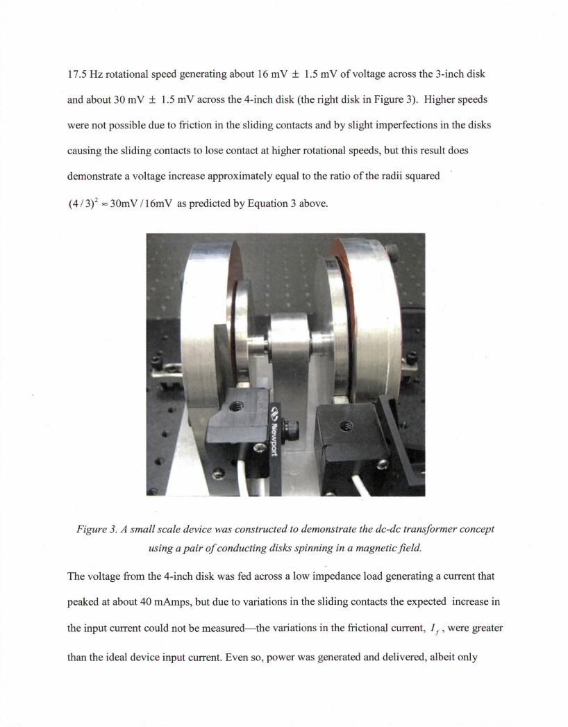
17.5 Hz rotational speed generating about 16 m V ± 1.5 m V of voltage across the 3-inch disk
and about 30 m V ± 1.5 m V across the 4-inch disk (the right disk in Figure 3). Higher speeds
were not possible due to friction in the sliding contacts and by slight imperfections in the disks
causing the sliding contacts to lose contact at higher rotational speeds, but this result does
demonstrate a voltage increase approximately equal to the ratio of the radii squared
( 4 I 3)2 = 30m V I 16m V as predicted by Equation 3 above.
Figure 3. A small scale device was constructed to demonstrate the de-de transformer concept
using a pair of conducting disks spinning in a magnetic field.
The voltage from the 4-inch disk was fed across a low impedance load generating a current that
peaked at about 40 mAmps, but due to variations in the sliding contacts the expected increase in
the input current could not be measured-the variations in the frictiona,l current, I 1 , were greater
than the ideal device input current. Even so, power was generated and delivered, albeit only
about 1 mW, with about 400 mW being used to overcome friction. Increased scaling would be
necessary to create an efficient, high power, device, but this "tqy" device has demonstrated the
basic operation of the concept, by shifting voltage up and delivering power.
Conclusions
A true de transformer has been described and demonstrated, but its utility is unclear. These
devices cannot compete with low power semiconductor based de converters, however, they can
be scaled to high power, where the primary need is for high voltage converters (kilovolts) for de
power transmission [2]. The difficulty is that homopolar generators are more suited to high
current, rather than high voltage, applications and have only been demonstrated up to 750 volts
[8]. Even so, with engineering this may be extended and they may find a role where their de
conversion potential coupled with their power filtering/storage capability may solve a need in the
rapidly growing area of high de power transmission.
Acknowledgements
The authors acknowledge funding from the NASA Office of the Chief Technologist. We also
acknowledge Robert B. Cox for fabrication and assembly of the prototype device.
References
1. N. Denniston, A.M. Massoud, S. Ahmed, and P. N. Enjeti, "Multiple-Module High-Gain
High-Voltage DC-DC Transformers for Offshore Wind Energy Systems," IEEE Trans.
Industrial Electronics, vol. 58, pp. 1877-1886, May 2011.
2. D. Jovcic, "Bidirectional, High-Power DC Transformer," IEEE Trans. Power Delivery,
vol. 24, pp. 2276-2283 , Oct. 2009.
3. W. Feng, P. Mattavelli, and F. C. Lee, "Pulsewidth Locked Loop (PWLL) for Automatic
Resonant Frequency Tracking in LLC DC-DC Transformer (LLC-DCX)," IEEE Trans.
Power Electronics, vol. 28, pp. 1862-1869, April 2013.
4. A. Ambramovitz and K. Smedley, "A Resonant DC-DC transformer with Zero Current
Ripple," IEEE Trans. Power Electronics, vol. 22, pp. 2344-2351, November 2007.
5. I. Giaver, "A de transformer," IEEE Spectrum, pp. 117-122, September 1966.
6. A. Arkkio, P. Berglund, J. T. Eriksson, J. Luomi, and M. Savelainen, "A 50 kW
Homopolar Motor with Superconducting Field Windings," IEEE Trans, Magnetics, vol.
MAG-17, pp. 900-903, January 1981.
7. R. J. Thome, W. Creedon, M. Reed, E. Bowles, and K. Schaubel, "Homopolar Motor
Technology Development," in 2002 IEEE Power Engineering Society Summer Meeting,
2002, pp. 260-264.
8. H. Devred, M. Martinez, and J. Huonic, "150 kVA, 56000 rpm, Turbo Engine Integrated
Homopolar Electrical Generator," in International Conference IEMD '99, Electric
Machines and Drives, 1999. Pp. 749-751.
9. J. H. Price, J. H. Gully, and M.D. Driga, "The High Voltage Homopolar Generator,"
IEEE Trans. Magnetics, vol. 22, pp. 1690-1694, November 1986.
10. R. C. Smith, "Homopolar transformer for conversion of electrical energy," Patent
5821659, Issued Oct. 13, 1998.
11. P. Lorrain and D. Corson, Electromagnetic Fields and Waves, 2nd Edition. San Francisco:
W. H. Freeman and Company, 1970, Chapter 8-Magnetic Fields 11-Induced
Electromotance and Magnetic Energy and Appendix C-Induced Electromotance in
Moving Systems.