Embed Size (px)
Citation preview
A DESIGN ANALYSIS OF MICROMIRRORS IN STACKED
CONFIGURATIONS WITH MOVING ELECTRODES
Sangtak Park, So-Ra Chung, and John T.W. Yeow
Department of Systems Design Engineering, University of Waterloo,
200 University Ave. W., Waterloo, Ontario, Canada
Email: [email protected]
Abstract- Micromirrors fabricated by MEMS technology have demonstrated to be important sensing
or actuating components in many industrial and biomedical applications such as laser scanning
displays, optical switch matrices, and biomedical imaging systems. In this paper, various actuation
mechanisms for micromirrors are described. A new geometric configuration of a stacked
micromirror that is actuated by electrostatic force is proposed and analyzed to show its superior
performance in terms of deflection angle, actuation voltage, and frequency response.
Index terms: Micromirror, MEMS, Electrostatic Force Actuation, Deflection Angle, Endoscope, OCT
(Optical Coherence Tomography), Stacked Micromirror Configuration
I. INTRODUCTION
Development of MicroElectroMechanical Systems (MEMS) technology in the past decades
has benefited automotive, communication and medical industries. Size and mass reduction
that are enabled by MEMS technology have improved the performance of devices such as
accelerometers, mass-flow sensors, bio-chips, RF devices, and automotive pressure sensors
[1]. Popular MEMS devices for optical applications are optical switch arrays for
communication [2], Optical Coherence Tomography (OCT) for an endoscope [3], confocal
laser scanning microscopy (CLSM) for obtaining high resolution images, and digital
micromirror devices for Digital Light Process (DLP) Projection.
MEMS micromirrors used for the above mentioned optical applications can be actuated via
electrostatic, magnetic, thermal, and piezoelectric mechanisms. Various actuation
mechanisms for sensing are presented in section II. Novel design and analytical modeling of
electrostatic actuation of micromirror configuration are presented in section III. Geometry and
design of stacked multiple electrode micromirror versus single micromirror configuration are
INTERNATIONAL JOURNAL ON SMART SENSING AND INTELLIGENT SYSTEMS, VOL. 1, NO. 2, JUNE 2008
480
presented in section IV. Numerical analysis with Finite Element Model (FEM) simulation for
each micromirror configuration is discussed in section V followed by the conclusion in
section VI.
II. MICROMIRROR ACTUATION METHODS FOR SENSING
2.1 Electromagnetic Actuation:
A micromirror can be deflected in two ways by electromagnetic actuation. First, by using
Lorentz force to move a patterned coil by exerting external magnetic field. Second, by
repulsive/attractive forces to repel/attract the magnetic material attached to the mirror from/to
the actuator [4]. Cugat et al [5] exhibits theoretical potential of magnetic microactuators and
systems (MAGMAS) using a permanent magnet in a micro-actuator. Advances in material
fabrication to provide thick film deposition of magnetic material on the surface of micro
actuators should reduce voltage and current requirements. Magnetic MEMS [6] can offer non-
contact operation, and can induce mechanical resonance by magnetic element excitation.
However, thermal budget imposed by the current CMOS technology limits the fabrication of
the magnetic film on the substrate from reaching the desired characteristics. Large angular
scan angle of 8° was achieved with 0.75 mA while showing linear response to the applied
current [7].
2.2 Piezoelectric Actuation:
The piezoelectric actuation takes advantage of the corresponding physical deformation to
applied electrical voltage property [8]. It has relatively lower operation voltage (3-20 Volt
DC) with low power consumption, better linearity, and fast switching time 0.1 to 1.0
milliseconds. For example, Y.Seo et. al has demonstrated 3.93 μm lateral displacement at 16
Volt [9].
2.3 Thermal Actuation:
The main advantage of thermal actuation is the simplicity of the fabrication method.
However, in general, thermal actuation tends to have higher power consumption and slow
response time. J. Singh et. al [10] demonstrated 10° of angular deflection with approximately
10 ms thermal response time when 1 V was applied to actuate the micromirror. The out-of-
plane thermal microactuator uses thermal expansion due to ohmic heating. A thin arm and
SANGTAK PARK, SO-RA CHUNG, AND JOHN T.W. YEOW, A DESIGN ANALYSIS OF MICROMIRRORS IN STACKED CONFIGURATIONS WITH MOVING ELECTRODES
481
wide arm configuration with one end fixed to the substrate has nonlinear property due to
temperature dependency [11].
2.4 Electrostatic Actuation:
Despite suffering from the pull-in effect, nonlinear behavior, and higher operating voltage, the
electrostatic actuation’s fast response time (less than 0.1 ms), low power consumption, and
the easiness of integration and testing with electrical control system make the electrostatic
actuation one of the preferred choices for micromirror actuation [12].
The operation voltage of the micromirror can be lowered while achieving more angular
deflection if the stiffness of torsion bar is reduced. However, when the stiffness is lowered,
the natural frequency of the micromirror also decreases, thereby reducing operational
bandwidth. In this paper, two novel configurations of a stacked micromirror are presented.
The proposed configuration has the potential to achieve more angular deflection at lower
actuation voltage without sacrificing frequency response.
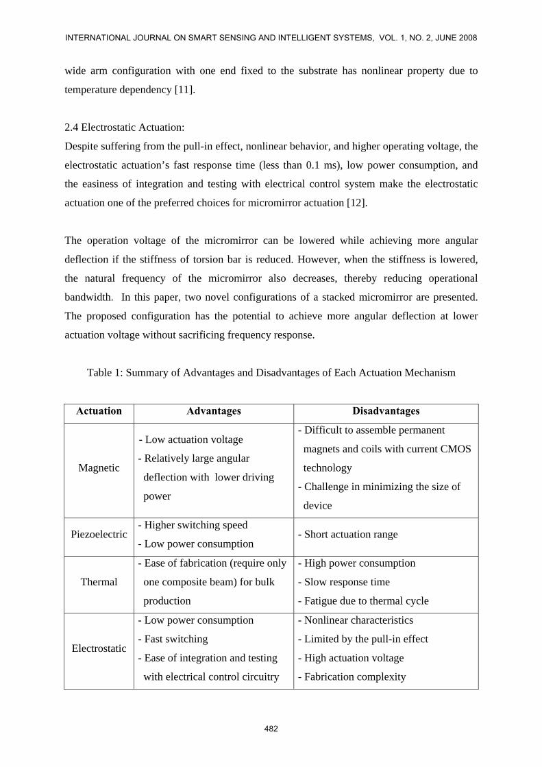
Table 1: Summary of Advantages and Disadvantages of Each Actuation Mechanism
Actuation Advantages Disadvantages
Magnetic
- Low actuation voltage
- Relatively large angular
deflection with lower driving
power
- Difficult to assemble permanent
magnets and coils with current CMOS
technology
- Challenge in minimizing the size of
device
Piezoelectric - Higher switching speed
- Low power consumption - Short actuation range
Thermal
- Ease of fabrication (require only
one composite beam) for bulk
production
- High power consumption
- Slow response time
- Fatigue due to thermal cycle
Electrostatic
- Low power consumption
- Fast switching
- Ease of integration and testing
with electrical control circuitry
- Nonlinear characteristics
- Limited by the pull-in effect
- High actuation voltage
- Fabrication complexity
INTERNATIONAL JOURNAL ON SMART SENSING AND INTELLIGENT SYSTEMS, VOL. 1, NO. 2, JUNE 2008
482
III. ANALYTICAL MODEL OF THE STACKED MICROMIRRORS
In this section, micromirrors of different configurations are presented and compared in terms
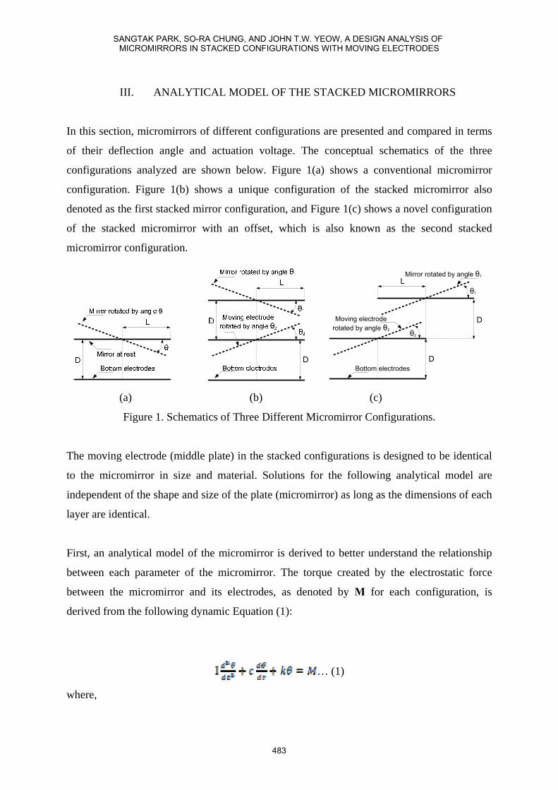
of their deflection angle and actuation voltage. The conceptual schematics of the three
configurations analyzed are shown below. Figure 1(a) shows a conventional micromirror
configuration. Figure 1(b) shows a unique configuration of the stacked micromirror also
denoted as the first stacked mirror configuration, and Figure 1(c) shows a novel configuration
of the stacked micromirror with an offset, which is also known as the second stacked
micromirror configuration.
θ1
D
L
D
θ2
Bottom electrodes
Mirror rotated by angle θ1
Moving electroderotated by angle θ2
(a) (b) (c)
Figure 1. Schematics of Three Different Micromirror Configurations.
The moving electrode (middle plate) in the stacked configurations is designed to be identical
to the micromirror in size and material. Solutions for the following analytical model are
independent of the shape and size of the plate (micromirror) as long as the dimensions of each
layer are identical.
First, an analytical model of the micromirror is derived to better understand the relationship
between each parameter of the micromirror. The torque created by the electrostatic force
between the micromirror and its electrodes, as denoted by M for each configuration, is
derived from the following dynamic Equation (1):
… (1)
where,
SANGTAK PARK, SO-RA CHUNG, AND JOHN T.W. YEOW, A DESIGN ANALYSIS OF MICROMIRRORS IN STACKED CONFIGURATIONS WITH MOVING ELECTRODES
483
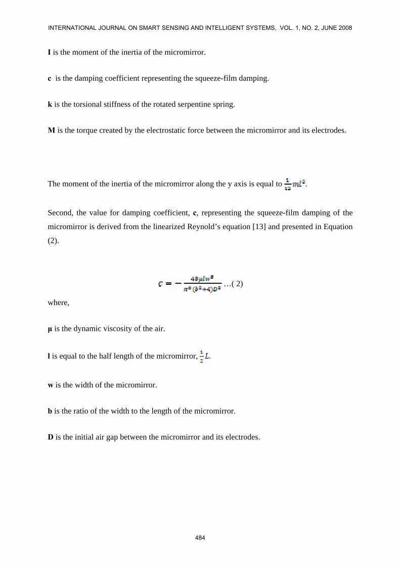
I is the moment of the inertia of the micromirror.
c is the damping coefficient representing the squeeze-film damping.
k is the torsional stiffness of the rotated serpentine spring.
M is the torque created by the electrostatic force between the micromirror and its electrodes.
The moment of the inertia of the micromirror along the y axis is equal to .
Second, the value for damping coefficient, c, representing the squeeze-film damping of the
micromirror is derived from the linearized Reynold’s equation [13] and presented in Equation
(2).
…( 2)
where,
μ is the dynamic viscosity of the air.
l is equal to the half length of the micromirror, .
w is the width of the micromirror.
b is the ratio of the width to the length of the micromirror.
D is the initial air gap between the micromirror and its electrodes.
INTERNATIONAL JOURNAL ON SMART SENSING AND INTELLIGENT SYSTEMS, VOL. 1, NO. 2, JUNE 2008
484
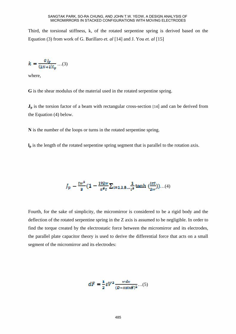
Third, the torsional stiffness, k, of the rotated serpentine spring is derived based on the
Equation (3) from work of G. Barillaro et. al [14] and J. You et. al [15]
…(3)
where,
G is the shear modulus of the material used in the rotated serpentine spring.
Jp is the torsion factor of a beam with rectangular cross-section [14] and can be derived from
the Equation (4) below.
N is the number of the loops or turns in the rotated serpentine spring.
lp is the length of the rotated serpentine spring segment that is parallel to the rotation axis.
…(4)
Fourth, for the sake of simplicity, the micromirror is considered to be a rigid body and the
deflection of the rotated serpentine spring in the Z axis is assumed to be negligible. In order to
find the torque created by the electrostatic force between the micromirror and its electrodes,
the parallel plate capacitor theory is used to derive the differential force that acts on a small
segment of the micromirror and its electrodes:
…(5)
SANGTAK PARK, SO-RA CHUNG, AND JOHN T.W. YEOW, A DESIGN ANALYSIS OF MICROMIRRORS IN STACKED CONFIGURATIONS WITH MOVING ELECTRODES
485
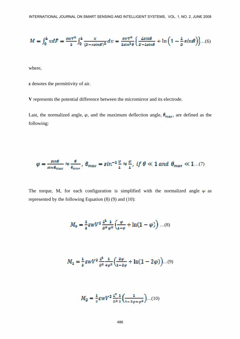
…(6)
where,
ε denotes the permittivity of air.
V represents the potential difference between the micromirror and its electrode.
Last, the normalized angle, , and the maximum deflection angle, , are defined as the
following:
…(7)
The torque, M, for each configuration is simplified with the normalized angle as
represented by the following Equation (8) (9) and (10):
…(8)
…(9)
…(10)
INTERNATIONAL JOURNAL ON SMART SENSING AND INTELLIGENT SYSTEMS, VOL. 1, NO. 2, JUNE 2008
486
where, M0 represents the torque created in the single mirror configuration. M1 and M2 denote
the torque generated in the first and second stacked mirror configurations, respectively. To
simplify the analysis, the fixed bottom electrodes are not used to actuate the micromirrors in
both stacked configurations.
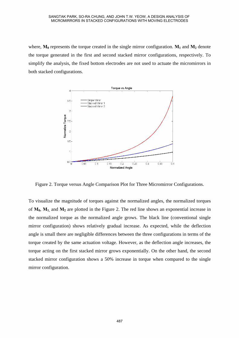
Figure 2. Torque versus Angle Comparison Plot for Three Micromirror Configurations.
To visualize the magnitude of torques against the normalized angles, the normalized torques
of M0, M1, and M2 are plotted in the Figure 2. The red line shows an exponential increase in
the normalized torque as the normalized angle grows. The black line (conventional single
mirror configuration) shows relatively gradual increase. As expected, while the deflection
angle is small there are negligible differences between the three configurations in terms of the
torque created by the same actuation voltage. However, as the deflection angle increases, the
torque acting on the first stacked mirror grows exponentially. On the other hand, the second
stacked mirror configuration shows a 50% increase in torque when compared to the single
mirror configuration.
SANGTAK PARK, SO-RA CHUNG, AND JOHN T.W. YEOW, A DESIGN ANALYSIS OF MICROMIRRORS IN STACKED CONFIGURATIONS WITH MOVING ELECTRODES
487
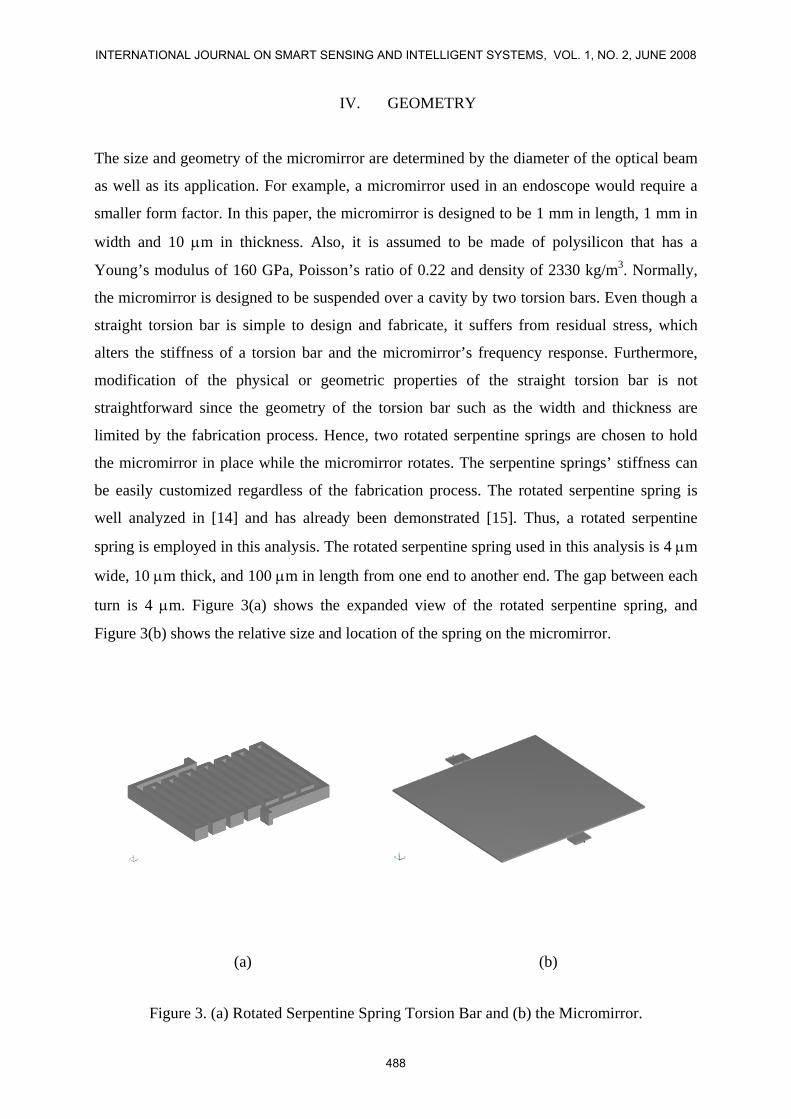
IV. GEOMETRY
The size and geometry of the micromirror are determined by the diameter of the optical beam
as well as its application. For example, a micromirror used in an endoscope would require a
smaller form factor. In this paper, the micromirror is designed to be 1 mm in length, 1 mm in
width and 10 μm in thickness. Also, it is assumed to be made of polysilicon that has a
Young’s modulus of 160 GPa, Poisson’s ratio of 0.22 and density of 2330 kg/m3. Normally,
the micromirror is designed to be suspended over a cavity by two torsion bars. Even though a
straight torsion bar is simple to design and fabricate, it suffers from residual stress, which
alters the stiffness of a torsion bar and the micromirror’s frequency response. Furthermore,
modification of the physical or geometric properties of the straight torsion bar is not
straightforward since the geometry of the torsion bar such as the width and thickness are
limited by the fabrication process. Hence, two rotated serpentine springs are chosen to hold
the micromirror in place while the micromirror rotates. The serpentine springs’ stiffness can
be easily customized regardless of the fabrication process. The rotated serpentine spring is
well analyzed in [14] and has already been demonstrated [15]. Thus, a rotated serpentine
spring is employed in this analysis. The rotated serpentine spring used in this analysis is 4 μm
wide, 10 μm thick, and 100 μm in length from one end to another end. The gap between each
turn is 4 μm. Figure 3(a) shows the expanded view of the rotated serpentine spring, and
Figure 3(b) shows the relative size and location of the spring on the micromirror.
(a) (b)
Figure 3. (a) Rotated Serpentine Spring Torsion Bar and (b) the Micromirror.
INTERNATIONAL JOURNAL ON SMART SENSING AND INTELLIGENT SYSTEMS, VOL. 1, NO. 2, JUNE 2008
488
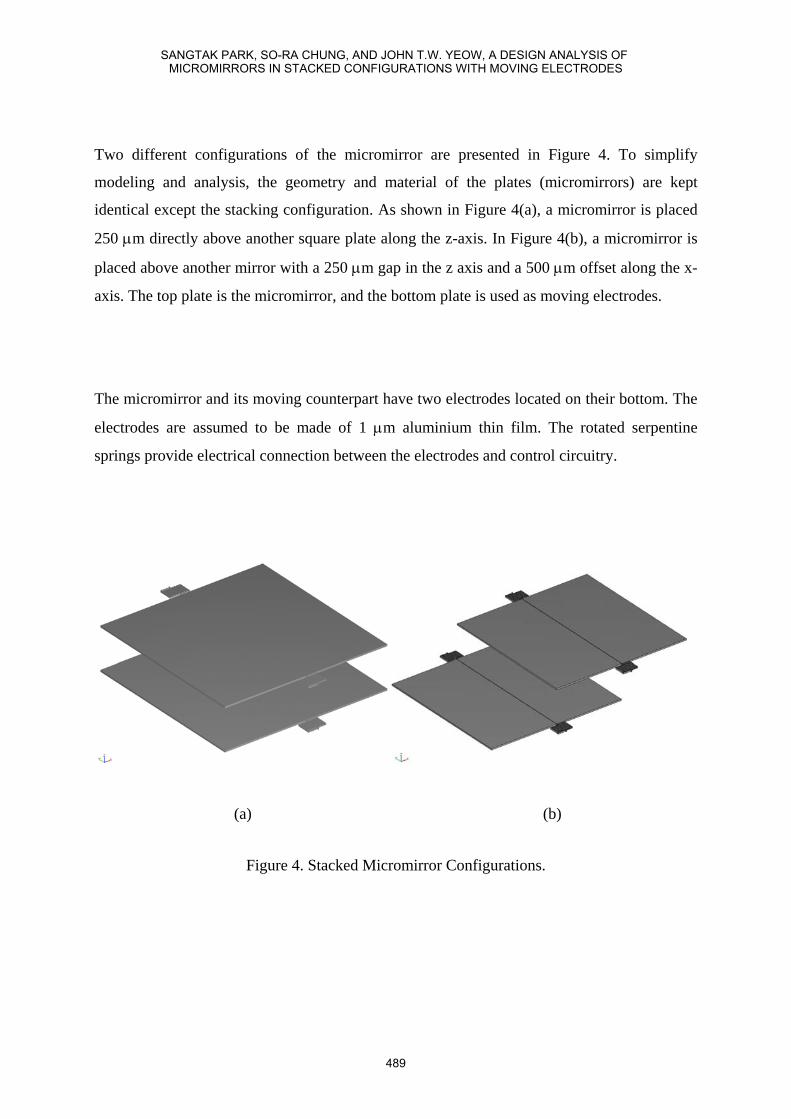
Two different configurations of the micromirror are presented in Figure 4. To simplify
modeling and analysis, the geometry and material of the plates (micromirrors) are kept
identical except the stacking configuration. As shown in Figure 4(a), a micromirror is placed
250 μm directly above another square plate along the z-axis. In Figure 4(b), a micromirror is
placed above another mirror with a 250 μm gap in the z axis and a 500 μm offset along the x-
axis. The top plate is the micromirror, and the bottom plate is used as moving electrodes.
The micromirror and its moving counterpart have two electrodes located on their bottom. The
electrodes are assumed to be made of 1 μm aluminium thin film. The rotated serpentine
springs provide electrical connection between the electrodes and control circuitry.
(a) (b)
Figure 4. Stacked Micromirror Configurations.
SANGTAK PARK, SO-RA CHUNG, AND JOHN T.W. YEOW, A DESIGN ANALYSIS OF MICROMIRRORS IN STACKED CONFIGURATIONS WITH MOVING ELECTRODES
489
V. NUMERIAL ANALYSIS AND RESUTLS
In this section, numerical analyses using COMSOL® are presented. The results are followed
by a discussion on the static deflection that is caused by varying actuation voltages.
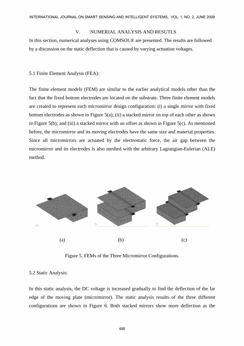
5.1 Finite Element Analysis (FEA):
The finite element models (FEM) are similar to the earlier analytical models other than the
fact that the fixed bottom electrodes are located on the substrate. Three finite element models
are created to represent each micromirror design configuration: (i) a single mirror with fixed
bottom electrodes as shown in Figure 5(a); (ii) a stacked mirror on top of each other as shown
in Figure 5(b); and (iii) a stacked mirror with an offset as shown in Figure 5(c). As mentioned
before, the micromirror and its moving electrodes have the same size and material properties.
Since all micromirrors are actuated by the electrostatic force, the air gap between the
micromirror and its electrodes is also meshed with the arbitrary Lagrangian-Eulerian (ALE)
method.
(a) (b) (c)
Figure 5. FEMs of the Three Micromirror Configurations.
5.2 Static Analysis:
In this static analysis, the DC voltage is increased gradually to find the deflection of the far
edge of the moving plate (micromirror). The static analysis results of the three different
configurations are shown in Figure 6. Both stacked mirrors show more deflection as the
INTERNATIONAL JOURNAL ON SMART SENSING AND INTELLIGENT SYSTEMS, VOL. 1, NO. 2, JUNE 2008
490
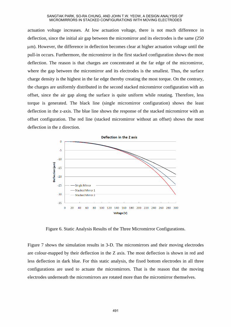
actuation voltage increases. At low actuation voltage, there is not much difference in
deflection, since the initial air gap between the micromirror and its electrodes is the same (250
μm). However, the difference in deflection becomes clear at higher actuation voltage until the
pull-in occurs. Furthermore, the micromirror in the first stacked configuration shows the most
deflection. The reason is that charges are concentrated at the far edge of the micromirror,
where the gap between the micromirror and its electrodes is the smallest. Thus, the surface
charge density is the highest in the far edge thereby creating the most torque. On the contrary,
the charges are uniformly distributed in the second stacked micromirror configuration with an
offset, since the air gap along the surface is quite uniform while rotating. Therefore, less
torque is generated. The black line (single micromirror configuration) shows the least
deflection in the z-axis. The blue line shows the response of the stacked micromirror with an
offset configuration. The red line (stacked micromirror without an offset) shows the most
deflection in the z direction.
Figure 6. Static Analysis Results of the Three Micromirror Configurations.
Figure 7 shows the simulation results in 3-D. The micromirrors and their moving electrodes
are colour-mapped by their deflection in the Z axis. The most deflection is shown in red and
less deflection in dark blue. For this static analysis, the fixed bottom electrodes in all three
configurations are used to actuate the micromirrors. That is the reason that the moving
electrodes underneath the micromirrors are rotated more than the micromirror themselves.
SANGTAK PARK, SO-RA CHUNG, AND JOHN T.W. YEOW, A DESIGN ANALYSIS OF MICROMIRRORS IN STACKED CONFIGURATIONS WITH MOVING ELECTRODES
491
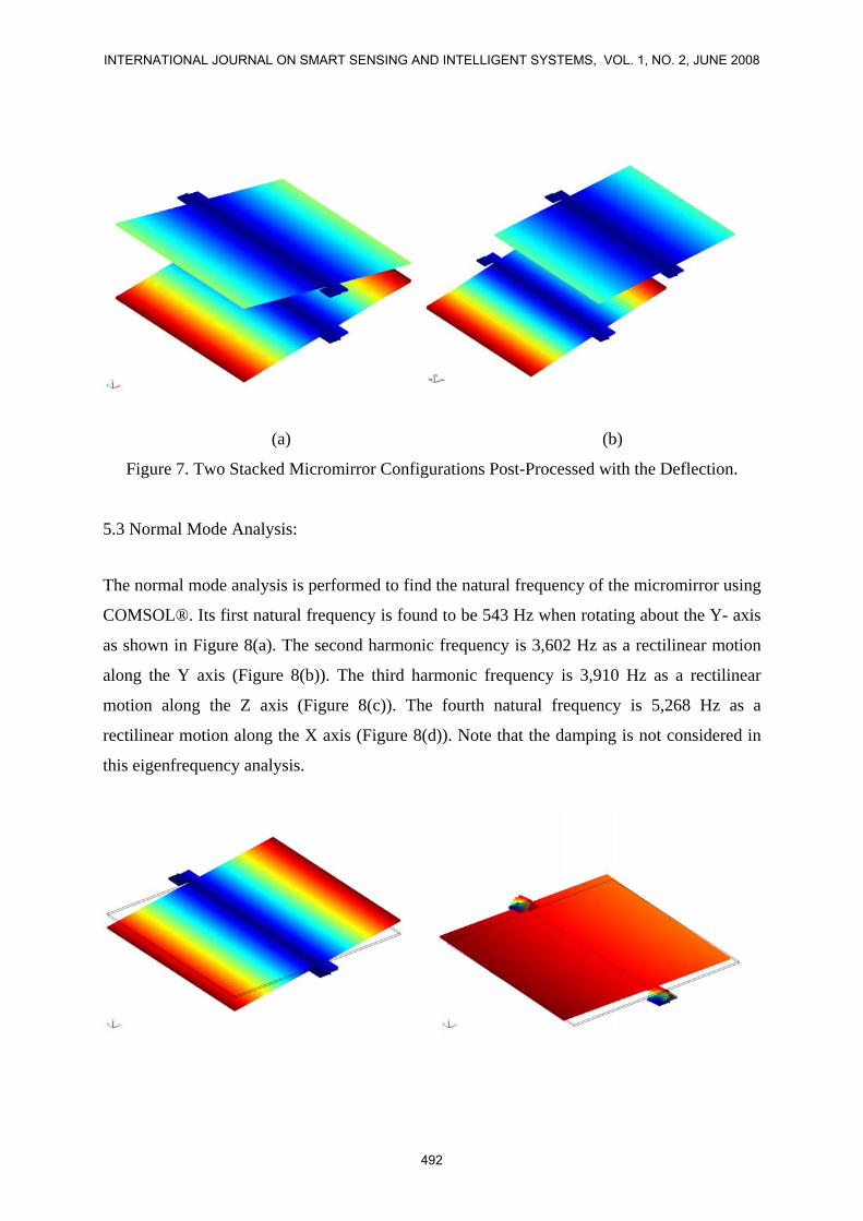
(a) (b)
Figure 7. Two Stacked Micromirror Configurations Post-Processed with the Deflection.
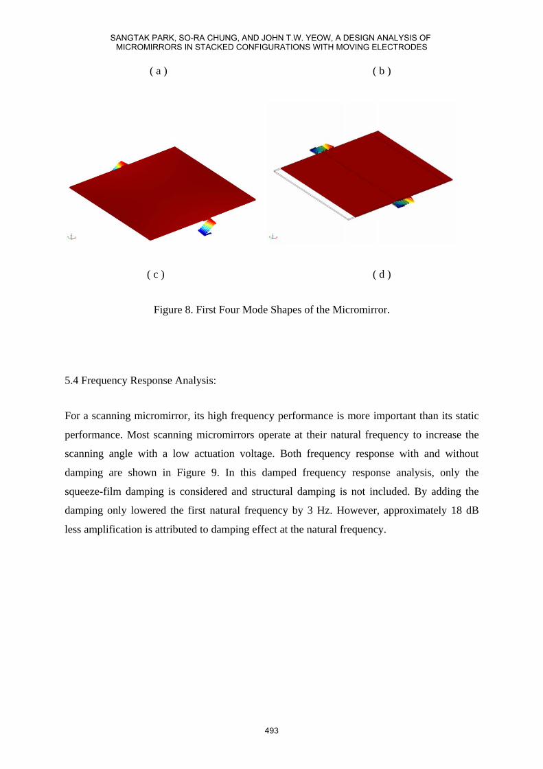
5.3 Normal Mode Analysis:
The normal mode analysis is performed to find the natural frequency of the micromirror using
COMSOL®. Its first natural frequency is found to be 543 Hz when rotating about the Y- axis
as shown in Figure 8(a). The second harmonic frequency is 3,602 Hz as a rectilinear motion
along the Y axis (Figure 8(b)). The third harmonic frequency is 3,910 Hz as a rectilinear
motion along the Z axis (Figure 8(c)). The fourth natural frequency is 5,268 Hz as a
rectilinear motion along the X axis (Figure 8(d)). Note that the damping is not considered in
this eigenfrequency analysis.
INTERNATIONAL JOURNAL ON SMART SENSING AND INTELLIGENT SYSTEMS, VOL. 1, NO. 2, JUNE 2008
492
( a ) ( b )
( c ) ( d )
Figure 8. First Four Mode Shapes of the Micromirror.
5.4 Frequency Response Analysis:
For a scanning micromirror, its high frequency performance is more important than its static
performance. Most scanning micromirrors operate at their natural frequency to increase the
scanning angle with a low actuation voltage. Both frequency response with and without
damping are shown in Figure 9. In this damped frequency response analysis, only the
squeeze-film damping is considered and structural damping is not included. By adding the
damping only lowered the first natural frequency by 3 Hz. However, approximately 18 dB
less amplification is attributed to damping effect at the natural frequency.
SANGTAK PARK, SO-RA CHUNG, AND JOHN T.W. YEOW, A DESIGN ANALYSIS OF MICROMIRRORS IN STACKED CONFIGURATIONS WITH MOVING ELECTRODES
493
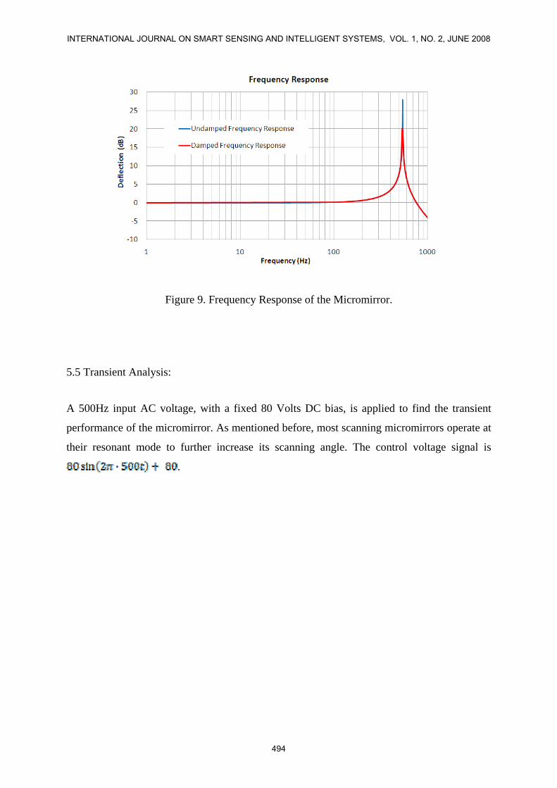
Figure 9. Frequency Response of the Micromirror.
5.5 Transient Analysis:
A 500Hz input AC voltage, with a fixed 80 Volts DC bias, is applied to find the transient
performance of the micromirror. As mentioned before, most scanning micromirrors operate at
their resonant mode to further increase its scanning angle. The control voltage signal is
.
INTERNATIONAL JOURNAL ON SMART SENSING AND INTELLIGENT SYSTEMS, VOL. 1, NO. 2, JUNE 2008
494
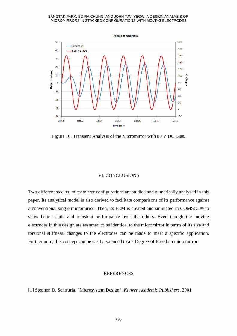
Figure 10. Transient Analysis of the Micromirror with 80 V DC Bias.
VI. CONCLUSIONS
Two different stacked micromirror configurations are studied and numerically analyzed in this
paper. Its analytical model is also derived to facilitate comparisons of its performance against
a conventional single micromirror. Then, its FEM is created and simulated in COMSOL® to
show better static and transient performance over the others. Even though the moving
electrodes in this design are assumed to be identical to the micromirror in terms of its size and
torsional stiffness, changes to the electrodes can be made to meet a specific application.
Furthermore, this concept can be easily extended to a 2 Degree-of-Freedom micromirror.
REFERENCES
[1] Stephen D. Sentruria, “Microsystem Design”, Kluwer Academic Publishers, 2001
SANGTAK PARK, SO-RA CHUNG, AND JOHN T.W. YEOW, A DESIGN ANALYSIS OF MICROMIRRORS IN STACKED CONFIGURATIONS WITH MOVING ELECTRODES
495
[2] Tze Wei Yeow, K. L. Eddie Law, and Andrew A. Goldenberg. "SOI-Based 2-D MEMS L-
Switching Matrix for Optical Networking." IEEE Jounal of Selected Topics in Quantum
Electronics, 2003: 603-613.
[3] J. T. W. Yeow, V. X. D. Yang, A. Chahwan, M. L. Gordon, B. Qi, I. A. Vitkin, B. C.
Wilson, A. A. Goldenberg. "Micromachined 2-D scanner for 3-D optical coherence
tomography." Sensors and Actuators A:Physical, 2005: 331-340.
[4] Takayuki Iseki, Miki Okumura and Takashi Sugawara. "Two-Dimensionally Deflecting
Mirror Using Electromagnetic Actuation." Optical Review, 2006: 189-194.
[5] Orphee Cugat, Jerome Delamare, and Gilbert Reyne. "Magnetic Micro-Actuators and
Systems (MAGMAS)." IEEE Transactions on Magnetics, 2003: 3607-3612.
[6] M R J Gibbs, E W Hill and P J Wright. "Magnetic materials for MEMS applications."
Journal of Physics D:Applied Physics, 2004: R237-R244.
[7] Jonathan J. Bernstein, William P. Taylor, John D. Brazzle, Christopher J. Corcoran,
Gregory Kirkos, Jefferson E. Odhner, Ajay Pareek, Marc Waelti, and Marvin Zai.
"Electromagnetically Actuated Mirror Arrays for Use in 3-D Optical Switching Applications."
Journal of Microelectromechanical Systems, 2004: 526-535.
[8] Robbins, William P. "High-Displacement Piezoelectric Actuator Utilizing a Meander-Line
Geometry-Part II:Therory." IEEETransactions on Ultrasonics, Ferroelectrics, and Frequency
Control, 1991: 461-467.
[9] Young Ho Seo, Doo-Sun Choi, Joon-Hyung Lee, Taik-Min Lee, Tae-Jin Je and Kyung-
Hyun Whang. "Piezoelectric Actuator Based on Stiffness Control and Stroke Amplication for
Large Lateral Actuation." IEEE International Conference on Micro Electro Mechanical
Systems. 2005. 383-386.
[10] Janak Singh, Terence Gan, Ajay Agarwal, Mohanraj, Saxon Liw. "3D free space
thermally actuated micromirror device." Sensors and Actuators A: Physical, 2005: 468-475.
[11] Atre, Amarendra. "Analysis of out-of-plane thermal microactuators." Journal of
Micromechanics and Microengineering, 2006: 250-213.
[12] Jeffery F Rhoads, Steven W Shaw, and Kimberly L Turner, “ The nonlinear response of
resonant microbeam systems with purely-parametric electrostatic actuation” Journal o f
Micromechanics and Microengineering, 2006: 890-899.
[13] Feixia Pan, Joel Kubby, Eric Peeters, Alex T. Tran, Subrata Mukherjee. "Squeeze Film
Damping Effect on the Dynamic Response of a MEMS Torsion Mirror." International
Conference on Modeling and Simulation of Microsystems. 1998. 474-479.
INTERNATIONAL JOURNAL ON SMART SENSING AND INTELLIGENT SYSTEMS, VOL. 1, NO. 2, JUNE 2008
496
[14] Giuseppe Barillaro, Antonio Molfese, Andrea Nannini and Francesco Pieri. "Analysis,
Simulation and relative performances of two kinds of serpentine springs." Journal of
Micromechnics and microengineering (IOP Publishing Ltd), 2005: 736-746.
[15] Jianliang You, Muthukumaran Packirisamy, Ion Stiharu. "Analysis, Simulation and
Testing of a Micromirror with Rotational Serpentine Springs." Intelligent Sensing and
Information Processing. 2005. 219-225.
SANGTAK PARK, SO-RA CHUNG, AND JOHN T.W. YEOW, A DESIGN ANALYSIS OF MICROMIRRORS IN STACKED CONFIGURATIONS WITH MOVING ELECTRODES
497