Embed Size (px)
Citation preview
A detailed description of an economicalsetup for electroporation of
chick embryos in ovo
R.M. Borges1*, J.H. Horne2*, A. Melo3, J.T. Vidal4, F.M. Vieceli1, M.O. Melo1, T.Y.N. Kanno1,
S.E. Fraser5 and C.Y.I. Yan1
1Departamento de Biologia Celular e do Desenvolvimento, Instituto de Ciencias Biomedicas,
Universidade de Sao Paulo, Sao Paulo, SP, Brasil2Department of Biology and Health Sciences, Pace University, New York, NY, USA
3Timpel S.A., Sao Paulo, SP, Brasil4Instituto de Pesquisas Energeticas e Nucleares, Sao Paulo, SP, Brasil
5Division of Biology, California Institute of Technology, Pasadena, CA, USA
Abstract
One of the challenges of the postgenomic era is characterizing the function and regulation of specific genes. For various
reasons, the early chick embryo can easily be adopted as an in vivo assay of gene function and regulation. The embryos are
robust, accessible, easily manipulated, and maintained in the laboratory. Genomic resources centered on vertebrate
organisms increase daily. As a consequence of optimization of gene transfer protocols by electroporation, the chick embryo will
probably become increasingly popular for reverse genetic analysis. The challenge of establishing chick embryonic
electroporation might seem insurmountable to those who are unfamiliar with experimental embryological methods. To
minimize the cost, time, and effort required to establish a chick electroporation assay method, we describe and illustrate in
great detail the procedures involved in building a low-cost electroporation setup and the basic steps of electroporation.
Key words: Electroporation; In vivo gene expression; Electroporator; Vertebrate embryo
Introduction
In the era of high-throughput genomic analysis, we are
faced with a staggering number of gene sequences
whose cellular functions have not been analyzed.
Furthermore, it is clear that characterizing noncoding
cis-regulatory sequences is essential for understanding
species-specific differences and similarities in expression
(1). For both scientific and practical reasons, the chick
embryo comes forward as a powerful model system that
can be used for posttranscriptomic analysis of gene
function and regulation.
The chick embryo is historically one of the first
experimental embryos used in developmental biology
research. Scientifically, the research results obtained from
this embryo are among the most important and most
numerous in this field (2,3). In addition, because of its
economic importance, much effort has been directed
toward sequencing, assembly, and mapping of the
chicken genome. The haploid chicken genome contains
1.26109 bp (4). The diploid karyotype is distributed in 9
pairs of large chromosomes and 30 pairs of microchromo-
somes (5). This genomehas been extensively characterized
by linkage mapping, and expression sequence tag
resources abound (2,6,7). Comparative mapping analysis
of the chicken, human and mouse genomes revealed a high
degree of synteny conservation between chickens and
mammals (8), and that the orthologous gene expression
profile between chickens and other vertebrates is similar (9).
Finally, the number of identified pseudogenes in chickens
(96) is significantly less than in humans (1069) or mice
(1351) (10).
The breakthrough in chick episomal gene misexpres-
sion came in 1997 with the introduction of in ovoelectroporation (11). Briefly, in ovo electroporation uses
a pulsed electric field to transiently permeabilize the
Correspondence: C.Y.I. Yan, Departamento de Biologia Celular e do Desenvolvimento, Instituto de Ciencias Biomedicas, USP, Av.
Prof. Lineu Prestes, 1524, 05508-900 Sao Paulo, SP, Brasil. E-mail: [email protected]
*These authors contributed equally to this study.
Received May 15, 2013. Accepted June 7, 2013. First published online September 16, 2013.
Brazilian Journal of Medical and Biological Research (2013) 46: 752-757, http://dx.doi.org/10.1590/1414-431X20133232
ISSN 1414-431X Short Communication
Braz J Med Biol Res 46(9) 2013 www.bjournal.com.br
plasma membrane, driving DNA entry toward the posi-
tively charged pole. Adjusting the values of the voltage
applied and delivering the current as square wave pulses
results in maximal delivery of DNA with minimal cell
death. Although viral infection is the method of choice for
transgenesis (12,13), electroporation provides the strongest
gene expression with no limit for the maximally transfectable
amount (11). Also, because the electrodes can be posi-
tioned at various sites on the embryo, the number of tissues
that can be targeted by electroporation is higher than with
viral infection or liposomal transfection. Moreover, the
expression of transgenes through electroporation occurs
much faster than with viral infection, which is a significant
advantage for analysis of early phenotypes (14). Finally, as
a reflection of its versatility, electroporation is being used in
an increasing number of animal models, including zebrafish
and mice (15,16).
Although the process of electroporation itself is rela-
tively simple and has been described previously (17-19), its
setup is still daunting to those who are unfamiliar with the
chick embryo or with the basic procedures used to
construct electrical devices. Moreover, most previous
articles recommend the purchase of commercially avail-
able electroporators, which can be a considerable invest-
ment for the laboratory that is considering the chick embryo
for in vivo gene function analysis.
We describe here in detail the steps required to build a
low-cost, working electroporation station using common
electrical parts and laboratory equipment. The electro-
porator described here was made by one of us (J.T. Vidal)
following the electrical diagram presented.
Material and Methods
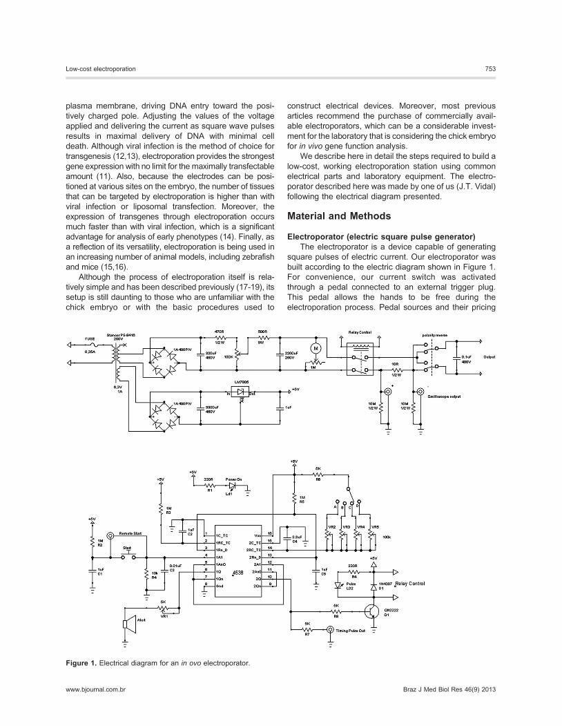
Electroporator (electric square pulse generator)The electroporator is a device capable of generating
square pulses of electric current. Our electroporator was
built according to the electric diagram shown in Figure 1.
For convenience, our current switch was activated
through a pedal connected to an external trigger plug.
This pedal allows the hands to be free during the
electroporation process. Pedal sources and their pricing
Figure 1. Electrical diagram for an in ovo electroporator.
Low-cost electroporation 753
www.bjournal.com.br Braz J Med Biol Res 46(9) 2013
vary. Suggested items are the Harvard Apparatus
injection foot switch (part Nos. 450211 or 450214,
Harvard Apparatus Company, USA), a simple electric
bass/amplifier foot switch, or the low-cost alternative
adopted in the lab - a sewing machine foot switch.
The electroporator diagram presented here allows
variation of pulse voltage (V), pulse duration time (L),
interval time between pulses (I), and number of pulses
(Figure 2A). All of these parameters have to be optimized
for different target tissues. There is already a plethora of
publications indicating the parameters for various targets
(17-22). The electroporator that we used in the experi-
ments demonstrated here has preset pulse duration times
and interval times, but an alternative model can be made
where these values are set by the user.
ElectrodesWe manufactured our own electrodes with platinum
wires shaped to fit the target tissue using the following
components: one bicolor copper cable for speakers (or
other flexible electronic cable), 0.5 mm2 cross-
section61800 mm length (or any workable length to
connect the electroporator to the embryo, which is placed
under the dissecting microscope); two banana-type plugs
to be inserted at the connection with the electroporator
(black for negative pole and red for positive pole) - there is
a diversity of banana-type plugs and diameter sets
available, and the only restriction is that the diameter of
the male plug has to fit the electroporator socket snugly
(female plug); two platinum wires, 0.5 mm diame-
ter610 mm length each, for the short electrode and
0.5 mm diameter615 mm for the long electrode; one
empty pen body; soldering iron and solder; sharp pliers for
stripping the cables; screwdriver for banana-plug screws;
hot glue gun and hot glue cartridge.
A 1-cm long piece of insulation was stripped from each
end of both copper speaker cables (Figure 2C-E). The
platinum wire was placed perpendicular to end of one of
the copper cables (Figure 2F), and the junction was
soldered (Figure 2I). Both red and black soldered cables
and platinum wire were inserted through an empty pen
body, leaving a 2-mm stretch protruding from the pen
body (Figure 2J). This allows visualization of the polarity
and correct positioning of the electrodes when electro-
porating. Both platinum wires were fixed in this position by
applying hot glue from the pen body base up to the
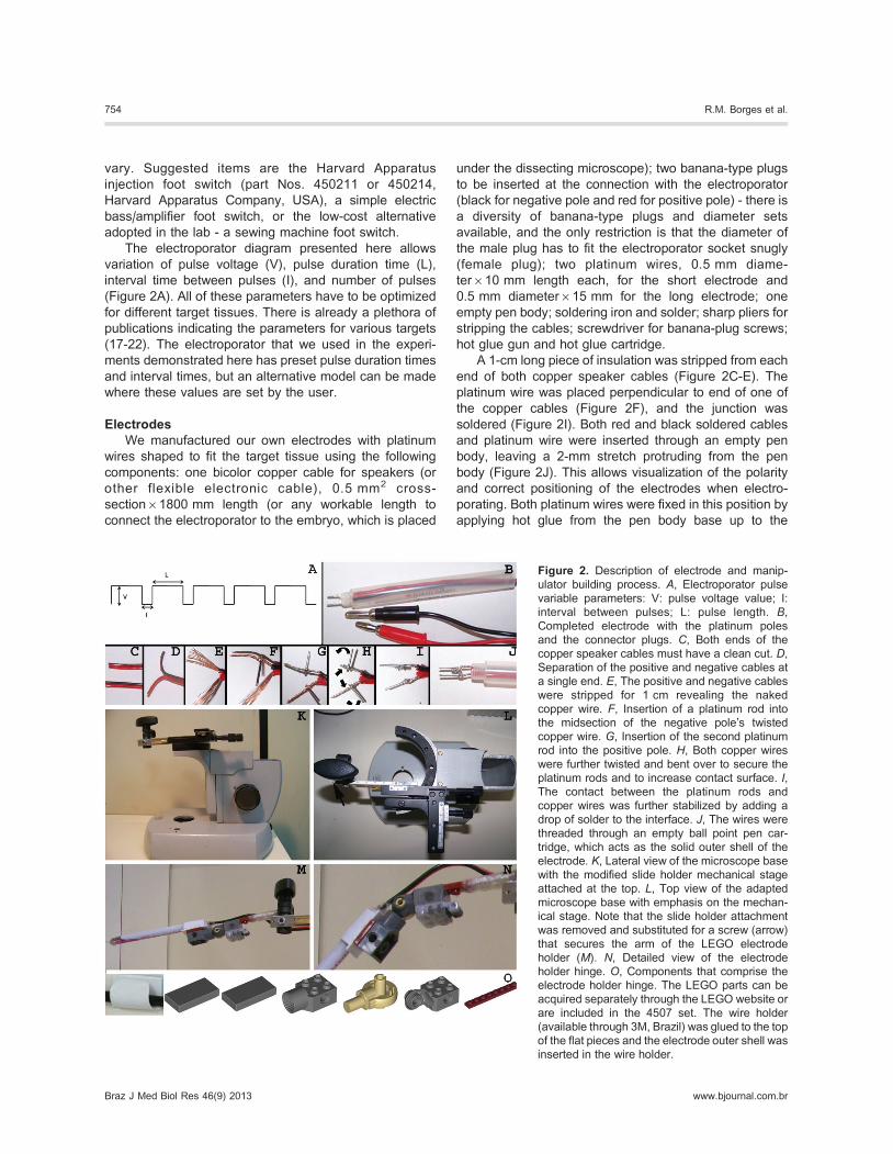
Figure 2. Description of electrode and manip-
ulator building process. A, Electroporator pulse
variable parameters: V: pulse voltage value; I:
interval between pulses; L: pulse length. B,Completed electrode with the platinum poles
and the connector plugs. C, Both ends of the
copper speaker cables must have a clean cut. D,Separation of the positive and negative cables at
a single end. E, The positive and negative cables
were stripped for 1 cm revealing the naked
copper wire. F, Insertion of a platinum rod into
the midsection of the negative pole’s twisted
copper wire. G, Insertion of the second platinum
rod into the positive pole. H, Both copper wires
were further twisted and bent over to secure the
platinum rods and to increase contact surface. I,The contact between the platinum rods and
copper wires was further stabilized by adding a
drop of solder to the interface. J, The wires were
threaded through an empty ball point pen car-
tridge, which acts as the solid outer shell of the
electrode. K, Lateral view of the microscope base
with the modified slide holder mechanical stage
attached at the top. L, Top view of the adapted
microscope base with emphasis on the mechan-
ical stage. Note that the slide holder attachment
was removed and substituted for a screw (arrow)
that secures the arm of the LEGO electrode
holder (M). N, Detailed view of the electrode
holder hinge. O, Components that comprise the
electrode holder hinge. The LEGO parts can be
acquired separately through the LEGO website or
are included in the 4507 set. The wire holder
(available through 3M, Brazil) was glued to the top
of the flat pieces and the electrode outer shell was
inserted in the wire holder.
754 R.M. Borges et al.
Braz J Med Biol Res 46(9) 2013 www.bjournal.com.br
platinum/speaker cable junctions (Figure 2B). At the other
end of the pen body, the banana plugs were soldered to
their color-matched copper cables. Alternatively, the
platinum electrodes can be constructed solder-free, with
epoxy resin (15).
Other materials can be used for the electrodes. For
example, tungsten wire is often used for microelectro-
porations (21-23). The main advantage of platinum over
tungsten is its stability over time. Platinum will not oxidize
with repeated use. On the other hand, tungsten wires can
be sharpened by electrolysis. The sharp point can be
used for microelectroporation, i.e., fine spatial definition of
target tissue (23).
To sharpen tungsten electrodes, we used a 12-V
AC/DC converter and soldered one of the poles to a
copper rod of approximately 5 cm in length and 2 mm in
diameter. To the other wire, we soldered an electric clamp
to hold the tungsten needle during the electrolysis
procedure. After inserting the needle in the clamp, we
immersed the copper rod in 5 M NaOH. Thereafter, we
briefly dipped the tungsten needle tip into the sodium
hydroxide to erode the tungsten needle. The appearance
of tiny bubbles at the tip signaled successful electrolysis.
The shape of the tip was monitored under a dissecting
scope. The resulting sharpened tip was extensively
washed prior to use.
MicromanipulatorIn some cases, such as electroporation of the neural
tube, the whole procedure can be performed freehand.
However, in other cases (e.g., lens placode), the injection
of the plasmid and the triggering of the pulses have to be
done simultaneously. Then, an electrode holder is
necessary to maintain electrode stability and to free the
hands. There are many commercially available micro-
manipulators that can be used (e.g., Narishige, Japan;
Sutter Instrument, USA; Harvard Apparatus Company).
We used a homemade, modified and recycled micro-
scope base with its mechanical stage translational control
device attached (Figure 2K and L). The microscope base
and arm contained the former focus knob and provided the
vertical movement necessary to position the electrode. The
x-y movement of the electrode was controlled by the
translational control knobs. A holder with a screw [Figure 2K
and L (arrow)] was attached to the extremity of the
mechanical stage to secure the electrode holder.
Alternatively, a simpler micromanipulator can be made with
a burette stand (Supplementary Figure S1). This latter
setup also allows gross adjustments in the z- and x-axes.
Electrode holderA holder facilitates adjustment of the angle of the
electrode when it approaches the embryo and minimizes
fatigue during a long electroporation procedure. We
have also manufactured an alternative electrode holder
made with LEGO1 articulated pieces (LEGO, Denmark;
Figure 2M-O). These articulated joints permit variations of
the angle between electrode and target tissue. The final
setup was positioned under the dissecting microscope
(Supplementary Figure S1).
Electroporation procedurePlasmids for microinjection were purified by columns
(Qiagen, USA, or Invitrogen, USA) and resuspended in
molecular biology grade water at concentrations ranging
from 2 to 4 mg/mL in a 0.05% Fast Green solution. The
Fast Green aids the visualization of the solution during
injection. This was then aspirated into glass needles
made from pulled glass capillary tubes. A popular source
for capillary glass is A-M Systems (Cat. #626000; USA).
Heparin-free glass capillary tubes for microhematocrit
assays (1.1 mm internal diameter/1.5 mm external
diameter/75 mm length) from a local biomedical supplier
work as well as those from A-M Systems.
The key to the injection process is the shape of the
pulled capillary needle. The neck of the needle must taper
slowly to a long thin needle (Supplementary Figure S1).
This shape allows access to the embryonic tissues with
minimal damage. And, if the needle tip needs to be broken
repeatedly due to clogging, the long thin shape minimizes
variations of bore size. This shape is better attained on a
microelectrode puller but can also be made over a Bunsen
burner after some practice.
DNA injection was done by mouth pipetting. The glass
needle was inserted into an aspirator tube (A5177; Sigma,
USA) and the mouthpiece was plugged with cotton to
minimize contamination of the embryo. The DNA was
injected in ovo into previously contrasted embryos (18)
(Supplementary Figure S2).
Results and Discussion
To express enhanced green fluorescence protein
(eGFP) in the neural tube and neural crest cells, we used
plasmid pMES, a bicistronic plasmid containing an
internal ribosomal entry site that allows expression of
the gene of interest together with eGFP (20). pMES was
injected into the neural tube lumen of HH10 embryos.
Immediately after injection of the DNA, we added 1 mL
Ringer’s saline to hydrate the embryo and lowered the
electrodes onto the amniotic membrane that covers the
embryo, aligning them to the injected neural tube with the
positive pole on the side to be electroporated. The ideal
shape for the electrode in this case was a double ‘‘L’’,
where the whole lower leg of the ‘‘L’’ contacted the
extraembryonic membrane at the sides of the embryo.
This shape ensures that a broad segment of the neural
tube is electroporated. The distance between the two
electrodes was 4 mm. Thereafter, we triggered a series of
electric pulses (4 pulses at 18 V with 30 ms duration and
intervals of 500 ms). We added 2-3 mL more of Ringer’s
solution, sealed the eggs with packing tape, and
Low-cost electroporation 755
www.bjournal.com.br Braz J Med Biol Res 46(9) 2013
reincubated them in an incubator at 37.76C with 50-55%
humidity for 2 days. The resulting neural tube expressed
cytoplasmic GFP unilaterally, corresponding to the side
where the positive electrode was positioned (Figure 3A).
Fluorescent cells in the neural tube and dorsal root
ganglion cells indicated successful targeting of neural
tube and neural crest cells. No signal was observed in
other embryonic tissues. Alternatively, the electroporation
can also be performed in slightly older embryos (HH12)
with different parameters (5 pulses at 20 V with 50 ms
duration and intervals of 100 ms).
Most of the regular eukaryotic expression vectors
driven by a cytomegalovirus or simian virus 40 promoter
will induce robust expression. Here, with the same
procedure described earlier, we labeled neural crest cell
nuclei and cell membranes after electroporation with
pCS2-TdTomato-2A-H2bGFP (Figure 3B). This expres-
sion vector encodes for a single fusion protein that
generates a membrane-targeted myristoylated red fluor-
escent protein and a nuclear-accumulated histone-GFP
fusion protein (24) (Figure 3B).
One can also change the configuration of the electrodes
according to the target-tissue anatomy and localization. For
instance, when the target was the preplacodal lens
ectoderm, we used straight platinum electrodes placed
perpendicularly to the underlying optic vesicle and exter-
nally to the embryo. The plasmid was injected externally,
close to the preplacodal ectoderm of HH9-10 embryos. As
the plasmid solution formed a cloud over the ectoderm, we
triggered the electric current concomitantly with the injection
(5 pulses at 9 V with 50 ms duration and 100-ms intervals).
This procedure provided specific labeling of the lens
placode, which could be visualized directly in whole mount
embryos (Figure 3C) or indirectly by immunofluorescence in
cryosections (Figure 3D).
In summary, these results show that introducing
embryonic electroporation and procedures in a laboratory
can be a low-cost setup that requires minimal effort with
maximal results.
Supplementary material
Click here to view [pdf].
Acknowledgments
The authors would like to thank Drs. Shankar Srinivas
(Oxford University) and Cathy Krull (University of
Michigan Medical School) for sharing the plasmids
pCS2-TdTomato-2A-H2bGFP and pMES, respectively.
Research partially supported by FAPESP and CNPq.
References
1. Lelli KM, SlatteryM,Mann RS. Disentangling themany layers
of eukaryotic transcriptional regulation. Annu Rev Genet
2012; 46: 43-68, doi: 10.1146/annurev-genet-110711-
155437.
2. Stern CD. The chick embryo - past, present and future as a
model system in developmental biology. Mech Dev 2004;
121: 1011-1013, doi: 10.1016/j.mod.2004.06.009.
3. Stern CD. The chick; a great model system becomes even
greater. Dev Cell 2005; 8: 9-17.
4. BrownWR, Hubbard SJ, Tickle C,Wilson SA. The chicken as
a model for large-scale analysis of vertebrate gene function.
Nat Rev Genet 2003; 4: 87-98, doi: 10.1038/nrg998.
5. Burt DW. The chicken genome and the developmental
biologist. Mech Dev 2004; 121: 1129-1135, doi: 10.1016/
j.mod.2004.04.020.
6. Groenen MA, Cheng HH, Bumstead N, Benkel BF, Briles
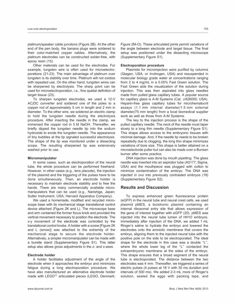
Figure 3. Electroporation results. A, Cross-section view of an
electroporated neural tube after cryosections and immunofluor-
escence detection of enhanced green fluorescent protein
(eGFP). The electroporated GFP-positive cells are restricted to
the right half of the neural tube and the right dorsal root ganglion
(DRG). GFP can also be detected in the commissural neurites
that cross to the contralateral neural tube and in the motor neuron
projections. Dorsal is up. B, Neural crest cells electroporated with
a plasmid encoding the fusion protein Tomato-2A-H2GFP, which
is cleaved intracellularly to label the cell membrane with red
fluorescence and the cell nucleus with green fluorescence. C,Fluorescence microscope view of a live embryo (embryonic day
3) with the electroporated right lens placode expressing GFP. D,Visualization of GFP (green) and actin (red) in the lens placode
after processing cryosections for immunofluorescence with anti-
GFP antibody (Abcam, UK) followed by exposure to rhodamine-
labeled phalloidin.
756 R.M. Borges et al.
Braz J Med Biol Res 46(9) 2013 www.bjournal.com.br
WE, Burke T, et al. A consensus linkage map of the chicken
genome. Genome Res 2000; 10: 137-147.
7. Wallis JW, Aerts J, Groenen MA, Crooijmans RP, Layman
D, Graves TA, et al. A physical map of the chicken genome.
Nature 2004; 432: 761-764, doi: 10.1038/nature03030.
8. Burt DW, Bruley C, Dunn IC, Jones CT, Ramage A, Law AS,
et al. The dynamics of chromosome evolution in birds and
mammals. Nature 1999; 402: 411-413, doi: 10.1038/46555.
9. Nie H, Crooijmans RP, Lammers A, van Schothorst EM, Keijer
J, Neerincx PB, et al. Gene expression in chicken reveals
correlation with structural genomic features and conserved
patterns of transcription in the terrestrial vertebrates. PLoS
One 2010; 5: e11990, doi: 10.1371/journal.pone.0011990.
10. Burt DW. Emergence of the chicken as a model organism:
implications for agriculture and biology. Poult Sci 2007; 86:
1460-1471.
11. Muramatsu T, Mizutani Y, Ohmori Y, Okumura J.
Comparison of three nonviral transfection methods for
foreign gene expression in early chicken embryos in ovo.
Biochem Biophys Res Commun 1997; 230: 376-380, doi:
10.1006/bbrc.1996.5882.
12. McGrew MJ, Sherman A, Ellard FM, Lillico SG, Gilhooley
HJ, Kingsman AJ, et al. Efficient production of germline
transgenic chickens using lentiviral vectors. EMBO Rep
2004; 5: 728-733, doi: 10.1038/sj.embor.7400171.
13. Ishii Y, Reese DE, Mikawa T. Somatic transgenesis using
retroviral vectors in the chicken embryo. Dev Dyn 2004;
229: 630-642, doi: 10.1002/dvdy.10484.
14. Ogura T. In vivo electroporation: a new frontier for gene
delivery and embryology. Differentiation 2002; 70: 163-171,
doi: 10.1046/j.1432-0436.2002.700406.x.
15. Hoegler KJ, Horne JH. Targeting the zebrafish optic tectum
using in vivo electroporation. Cold Spring Harb Protoc 2010;
2010: pdb.prot5463, doi: 10.1101/pdb.prot5463.
16. Calegari F, Marzesco AM, Kittler R, Buchholz F, Huttner
WB. Tissue-specific RNA interference in post-implantation
mouse embryos using directional electroporation and whole
embryo culture. Differentiation 2004; 72: 92-102, doi:
10.1111/j.1432-0436.2004.07202002.x.
17. Croteau LP, Kania A. Optimisation of in ovo electroporation
of the chick neural tube. J Neurosci Methods 2011; 201:
381-384, doi: 10.1016/j.jneumeth.2011.08.012.
18. Sauka-Spengler T, Barembaum M. Gain- and loss-of-
function approaches in the chick embryo. Methods Cell Biol
2008; 87: 237-256, doi: 10.1016/S0091-679X(08)00212-4.
19. Krull CE. A primer on using in ovo electroporation to analyze
gene function. Dev Dyn 2004; 229: 433-439, doi: 10.1002/
dvdy.10473.
20. Swartz M, Eberhart J, Mastick GS, Krull CE. Sparking new
frontiers: using in vivo electroporation for genetic manipula-
tions. Dev Biol 2001; 233: 13-21, doi: 10.1006/dbio.2001.0181.
21. Scaal M, Gros J, Lesbros C, Marcelle C. In ovo electro-
poration of avian somites. Dev Dyn 2004; 229: 643-650, doi:
10.1002/dvdy.10433.
22. Yasuda K, Momose T, Takahashi Y. Applications of
microelectroporation for studies of chick embryogenesis.
Dev Growth Differ 2000; 42: 203-206, doi: 10.1046/j.1440-
169x.2000.00502.x.
23. Momose T, Tonegawa A, Takeuchi J, Ogawa H, Umesono
K, Yasuda K. Efficient targeting of gene expression in chick
embryos by microelectroporation. Dev Growth Differ 1999;
41: 335-344, doi: 10.1046/j.1440-169X.1999.413437.x.
24. Trichas G, Begbie J, Srinivas S. Use of the viral 2A peptide
for bicistronic expression in transgenic mice. BMC Biol
2008; 6: 40, doi: 10.1186/1741-7007-6-40.
25. Hamburger V, Hamilton HL. A series of normal stages in the
development of the chick embryo. Dev Dyn 1992; 195: 231-
272, doi: 10.1002/aja.1001950404.
Low-cost electroporation 757
www.bjournal.com.br Braz J Med Biol Res 46(9) 2013