Embed Size (px)
Citation preview
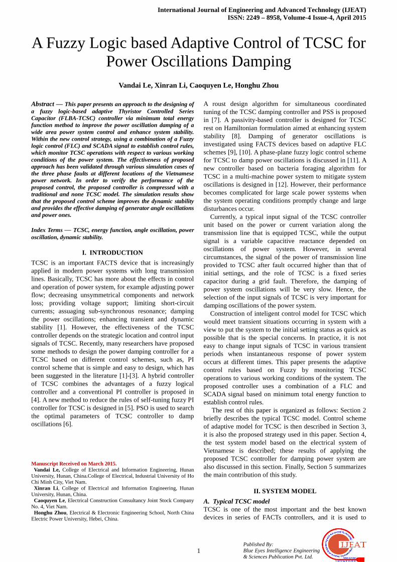
International Journal of Engineering and Advanced Technology (IJEAT) ISSN: 2249 – 8958, Volume-4 Issue-4, April 2015
1 Published By: Blue Eyes Intelligence Engineering & Sciences Publication Pvt. Ltd.
A Fuzzy Logic based Adaptive Control of TCSC for Power Oscillations Damping
Vandai Le, Xinran Li, Caoquyen Le, Honghu Zhou
Abstract — This paper presents an approach to the designing of a fuzzy logic-based adaptive Thyristor Controlled Series Capacitor (FLBA-TCSC) controller via minimum total energy function method to improve the power oscillation damping of a wide area power system control and enhance system stability. Within the new control strategy, using a combination of a Fuzzy logic control (FLC) and SCADA signal to establish control rules, which monitor TCSC operations with respect to various working conditions of the power system. The effectiveness of proposed approach has been validated through various simulation cases of the three phase faults at different locations of the Vietnamese power network. In order to verify the performance of the proposed control, the proposed controller is compressed with a traditional and none TCSC model. The simulation results show that the proposed control scheme improves the dynamic stability and provides the effective damping of generator angle oscillations and power ones. Index Terms — TCSC, energy function, angle oscillation, power oscillation, dynamic stability.
I. INTRODUCTION
TCSC is an important FACTS device that is increasingly applied in modern power systems with long transmission lines. Basically, TCSC has more about the effects in control and operation of power system, for example adjusting power flow; decreasing unsymmetrical components and network loss; providing voltage support; limiting short-circuit currents; assuaging sub-synchronous resonance; damping the power oscillations; enhancing transient and dynamic stability [1]. However, the effectiveness of the TCSC controller depends on the strategic location and control input signals of TCSC. Recently, many researchers have proposed some methods to design the power damping controller for a TCSC based on different control schemes, such as, PI control scheme that is simple and easy to design, which has been suggested in the literature [1]-[3]. A hybrid controller of TCSC combines the advantages of a fuzzy logical controller and a conventional PI controller is proposed in [4]. A new method to reduce the rules of self-tuning fuzzy PI controller for TCSC is designed in [5]. PSO is used to search the optimal parameters of TCSC controller to damp oscillations [6]. Manuscript Received on March 2015. Vandai Le, College of Electrical and Information Engineering, Hunan University, Hunan, China.College of Electrical, Industrial University of Ho Chi Minh City, Viet Nam. Xinran Li , College of Electrical and Information Engineering, Hunan University, Hunan, China. Caoquyen Le, Electrical Construction Consultancy Joint Stock Company No. 4, Viet Nam. Honghu Zhou, Electrical & Electronic Engineering School, North China Electric Power University, Hebei, China.
A roust design algorithm for simultaneous coordinated tuning of the TCSC damping controller and PSS is proposed in [7]. A passivity-based controller is designed for TCSC rest on Hamiltonian formulation aimed at enhancing system stability [8]. Damping of generator oscillations is investigated using FACTS devices based on adaptive FLC schemes [9], [10]. A phase-plane fuzzy logic control scheme for TCSC to damp power oscillations is discussed in [11]. A new controller based on bacteria foraging algorithm for TCSC in a multi-machine power system to mitigate system oscillations is designed in [12]. However, their performance becomes complicated for large scale power systems when the system operating conditions promptly change and large disturbances occur.
Currently, a typical input signal of the TCSC controller unit based on the power or current variation along the transmission line that is equipped TCSC, while the output signal is a variable capacitive reactance depended on oscillations of power system. However, in several circumstances, the signal of the power of transmission line provided to TCSC after fault occurred higher than that of initial settings, and the role of TCSC is a fixed series capacitor during a grid fault. Therefore, the damping of power system oscillations will be very slow. Hence, the selection of the input signals of TCSC is very important for damping oscillations of the power system.
Construction of inteligent control model for TCSC which would meet transient situations occurring in system with a view to put the system to the initial setting status as quick as possible that is the special concerns. In practice, it is not easy to change input signals of TCSC in various transient periods when instantaneous response of power system occurs at different times. This paper presents the adaptive control rules based on Fuzzy by monitoring TCSC operations to various working conditions of the system. The proposed controller uses a combination of a FLC and SCADA signal based on minimum total energy function to establish control rules.
The rest of this paper is organized as follows: Section 2 briefly describes the typical TCSC model. Control scheme of adaptive model for TCSC is then described in Section 3, it is also the proposed strategy used in this paper. Section 4, the test system model based on the electrical system of Vietnamese is described; these results of applying the proposed TCSC controller for damping power system are also discussed in this section. Finally, Section 5 summarizes the main contribution of this study.
II. SYSTEM MODEL
A. Typical TCSC model TCSC is one of the most important and the best known devices in series of FACTs controllers, and it is used to
A Fuzzy Logic based Adaptive Control of TCSC for Power Oscillations Damping
2 Published By: Blue Eyes Intelligence Engineering & Sciences Publication Pvt. Ltd.
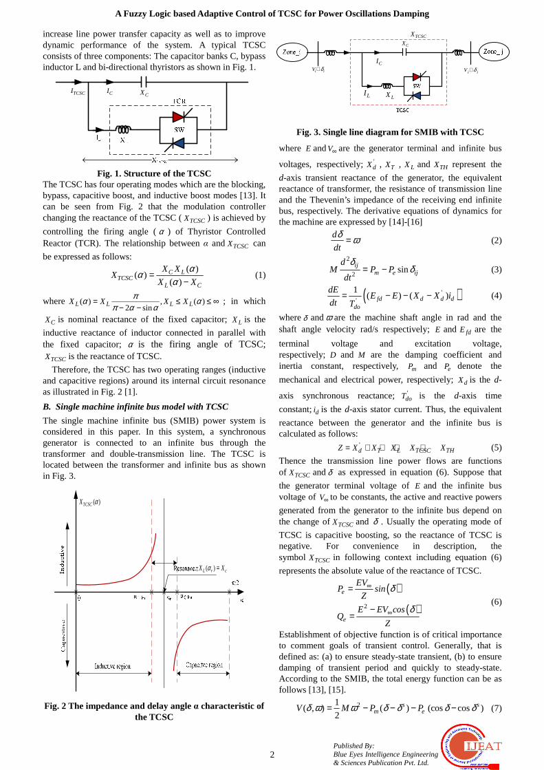
increase line power transfer capacity as well as to improve dynamic performance of the system. A typical TCSC consists of three components: The capacitor banks C, bypass inductor L and bi-directional thyristors as shown in Fig. 1.
CXCITCSCI
Fig. 1. Structure of the TCSC
The TCSC has four operating modes which are the blocking, bypass, capacitive boost, and inductive boost modes [13]. It can be seen from Fig. 2 that the modulation controller changing the reactance of the TCSC (TCSCX ) is achieved by
controlling the firing angle (α ) of Thyristor Controlled Reactor (TCR). The relationship between α and TCSCX can
be expressed as follows: ( )
( )( )C L
TCSCL C
X XX
X X
ααα
=−
(1)
where ( ) , ( )2 sinL L L LX X X X
πα απ α α
= ≤ ≤ ∞− −
; in which
CX is nominal reactance of the fixed capacitor; LX is the
inductive reactance of inductor connected in parallel with the fixed capacitor; α is the firing angle of TCSC;
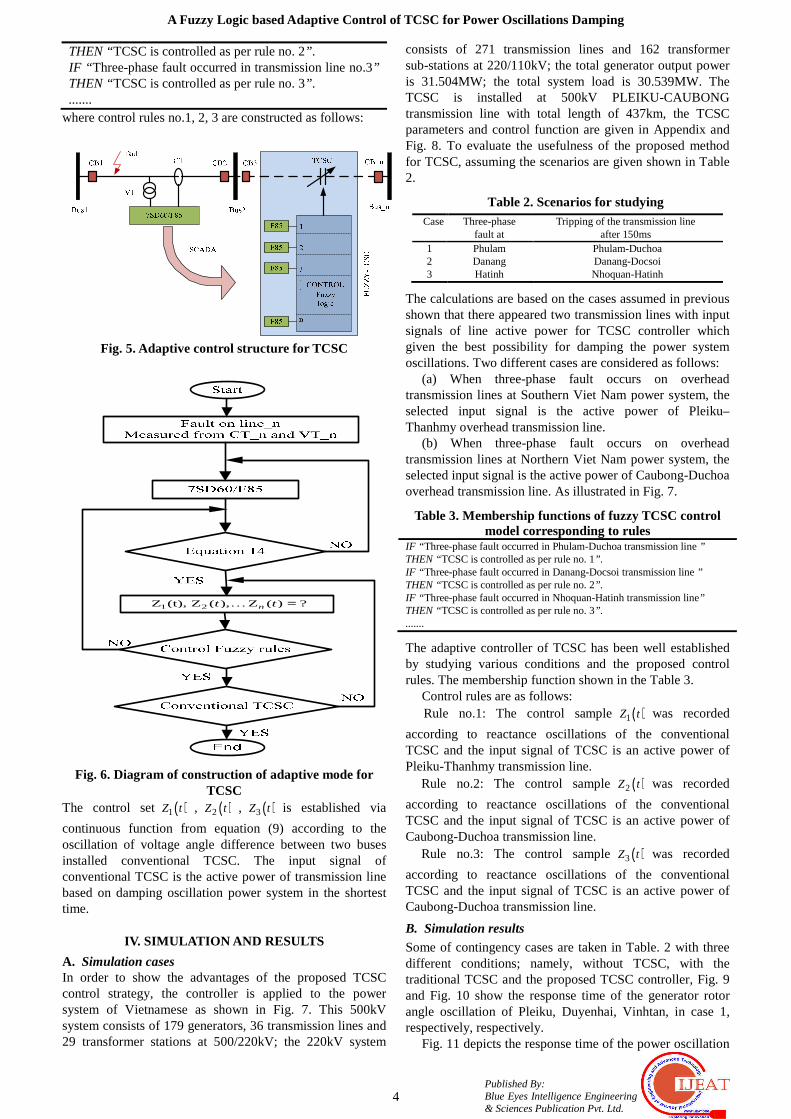
TCSCX is the reactance of TCSC. Therefore, the TCSC has two operating ranges (inductive
and capacitive regions) around its internal circuit resonance as illustrated in Fig. 2 [1].
B. Single machine infinite bus model with TCSC
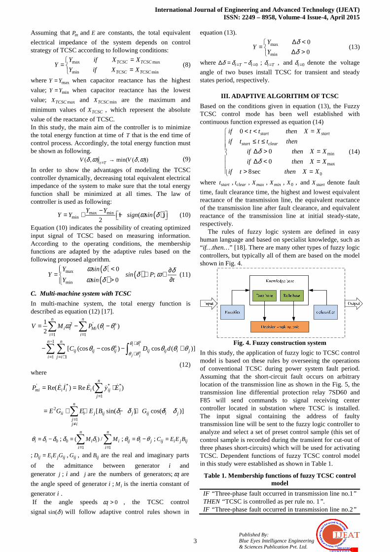
The single machine infinite bus (SMIB) power system is considered in this paper. In this system, a synchronous generator is connected to an infinite bus through the transformer and double-transmission line. The TCSC is located between the transformer and infinite bus as shown in Fig. 3.
( )TCSCX α
( )L r cX Xα =
Fig. 2 The impedance and delay angle α characteristic of
the TCSC
CI
CXTCSCX
j jV δ∠
LILX
i iV δ∠
Fig. 3. Single line diagram for SMIB with TCSC
where E andV∞ are the generator terminal and infinite bus
voltages, respectively; 'dX , TX , LX and THX represent the
d-axis transient reactance of the generator, the equivalent reactance of transformer, the resistance of transmission line and the Thevenin’s impedance of the receiving end infinite bus, respectively. The derivative equations of dynamics for the machine are expressed by [14]-[16]
d
dt
δ ω=
(2)
2
2sin
ijm e ij
dM P P
dt
δδ= −
(3)
( )''
1( ) ( )fd d d d
do
dEE E X X i
dt T= − − −
(4)
whereδ andω are the machine shaft angle in rad and the shaft angle velocity rad/s respectively; E and fdE are the
terminal voltage and excitation voltage, respectively;D and M are the damping coefficient and inertia constant, respectively, mP and eP denote the
mechanical and electrical power, respectively; dX is the d-
axis synchronous reactance;'doT is the d-axis time
constant;di is the d-axis stator current. Thus, the equivalent
reactance between the generator and the infinite bus is calculated as follows:
'd T L TCSC THZ X X X X X= + + + + (5)
Thence the transmission line power flows are functions of TCSCX andδ as expressed in equation (6). Suppose that
the generator terminal voltage of E and the infinite bus voltage of V∞ to be constants, the active and reactive powers
generated from the generator to the infinite bus depend on the change of TCSCX and δ . Usually the operating mode of
TCSC is capacitive boosting, so the reactance of TCSC is negative. For convenience in description, the symbol TCSCX in following context including equation (6)
represents the absolute value of the reactance of TCSC.
( )
( )2
e
e
EVP
Z
E EV cosQ
Z
sin δ
δ
∞
∞
=
−=
(6)
Establishment of objective function is of critical importance to comment goals of transient control. Generally, that is defined as: (a) to ensure steady-state transient, (b) to ensure damping of transient period and quickly to steady-state. According to the SMIB, the total energy function can be as follows [13], [15].
21( , ) ( ) (cos cos )
2s s
m eV M P Pδ ω ω δ δ δ δ= − − − −
(7)
International Journal of Engineering and Advanced Technology (IJEAT) ISSN: 2249 – 8958, Volume-4 Issue-4, April 2015
3 Published By: Blue Eyes Intelligence Engineering & Sciences Publication Pvt. Ltd.
Assuming that mP andE are constants, the total equivalent
electrical impedance of the system depends on control strategy of TCSC according to following conditions:
max max
min min
TCSC TCSC
TCSC TCSC
Y if X XY
Y if X X
== =
(8)
where maxY Y= when capacitor reactance has the highest
value; minY Y= when capacitor reactance has the lowest
value; maxTCSCX and minTCSCX are the maximum and
minimum values of TCSCX , which represent the absolute
value of the reactance of TCSC. In this study, the main aim of the controller is to minimize the total energy function at time of T that is the end time of control process. Accordingly, the total energy function must be shown as following.
( , ) min( ( , ))t T
V Vδ ω δ ω= →
(9) In order to show the advantages of modeling the TCSC controller dynamically, decreasing total equivalent electrical impedance of the system to make sure that the total energy function shall be minimized at all times. The law of controller is used as following:
( )max min
min 1 ( )2
Y YY Y sign sinδω−
= + −
(10)
Equation (10) indicates the possibility of creating optimized input signal of TCSC based on measuring information. According to the operating conditions, the membership functions are adapted by the adaptive rules based on the following proposed algorithm.
( )( ) ( )max
min
0;
0
YY P
t
sinsin
sinY
δδ
δω δωω
< ∂= ∈ ∈ ∂> (11)
C. Multi-machine system with TCSC
In multi-machine system, the total energy function is described as equation (12) [17].
2 '
1 1
1
1 1
1( )
2
[ (cos cos ) cos ( )]s
i i
sj j
n ns
i i Mi i ii i
n ns
ij ij ij ij ij i ji j i
V M P
C D dθ θ
θ θ
ω θ θ
θ θ θ θ θ
= =− +
+= = +
= − −
− − − +
∑ ∑
∑∑ ∫ (12)
where
' * * *
1
2
1
Re( ) Re ( )
[ sin( ) cos( )]
n
mi i i i ij ij
n
ii i j ij i j ij i jjj i
P E I E y E
E G E E B Gδ δ δ δ
=
=≠
= = ⋅
= + ⋅ − + −
∑
∑
& & & &&
0i iθ δ δ= − ; 0
1 1
( ) /n n
i i i
i i
M Mδ δ= =
= ∑ ∑ ; ij i jθ θ θ= − ; ij i j ijC E E B=
; ij i j ijD E E G= , ijG , and ijB are the real and imaginary parts
of the admittance between generator i and generator j ; i and j are the numbers of generators;iω are
the angle speed of generator i ; iM is the inertia constant of
generator i . If the angle speeds 0iω > , the TCSC control
signalsin( )δ will follow adaptive control rules shown in
equation (13).
max
min
0
0
YY
Y
δδ
∆ <= ∆ >
(13)
where 0t T tδ δ δ= =∆ = − ; t Tδ = , and 0tδ = denote the voltage
angle of two buses install TCSC for transient and steady states period, respectively.
III. ADAPTIVE ALGORITHM OF TCSC
Based on the conditions given in equation (13), the Fuzzy TCSC control mode has been well established with continuous function expressed as equation (14)
min
max
0
0
0
0
8sec
start start
start clear
if t t then X X
if t t t then
if then X X
if then X X
if t then X X
δδ
< < = ≤ ≤ ∆ > = ∆ < = > =
(14)
where startt , cleart , maxX , minX , 0X , and startX denote fault
time, fault clearance time, the highest and lowest equivalent reactance of the transmission line, the equivalent reactance of the transmission line after fault clearance, and equivalent reactance of the transmission line at initial steady-state, respectively.
The rules of fuzzy logic system are defined in easy human language and based on specialist knowledge, such as “ if…then…” [18]. There are many other types of fuzzy logic controllers, but typically all of them are based on the model shown in Fig. 4.
Fig. 4. Fuzzy construction system
In this study, the application of fuzzy logic to TCSC control model is based on these rules by overseeing the operations of conventional TCSC during power system fault period. Assuming that the short-circuit fault occurs on arbitrary location of the transmission line as shown in the Fig. 5, the transmission line differential protection relay 7SD60 and F85 will send commands to signal receiving center controller located in substation where TCSC is installed. The input signal containing the address of faulty transmission line will be sent to the fuzzy logic controller to analyze and select a set of preset control sample (this set of control sample is recorded during the transient for cut-out of three phases short-circuits) which will be used for activating TCSC. Dependent functions of fuzzy TCSC control model in this study were established as shown in Table 1.
Table 1. Membership functions of fuzzy TCSC control model
IF “ Three-phase fault occurred in transmission line no.1” THEN “TCSC is controlled as per rule no. 1”. IF “ Three-phase fault occurred in transmission line no.2”
A Fuzzy Logic based Adaptive Control of TCSC for Power Oscillations Damping
4 Published By: Blue Eyes Intelligence Engineering & Sciences Publication Pvt. Ltd.
THEN “TCSC is controlled as per rule no. 2”. IF “ Three-phase fault occurred in transmission line no.3” THEN “TCSC is controlled as per rule no. 3”. .......
where control rules no.1, 2, 3 are constructed as follows:
Fig. 5. Adaptive control structure for TCSC
1 2Z (t), Z ( ), Z ( ) ?nt t =K
Fig. 6. Diagram of construction of adaptive mode for TCSC
The control set ( )1Z t , ( )2Z t , ( )3Z t is established via
continuous function from equation (9) according to the oscillation of voltage angle difference between two buses installed conventional TCSC. The input signal of conventional TCSC is the active power of transmission line based on damping oscillation power system in the shortest time.
IV. SIMULATION AND RESULTS
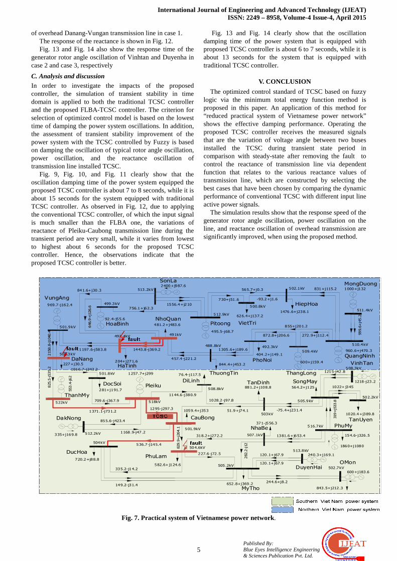
A. Simulation cases In order to show the advantages of the proposed TCSC control strategy, the controller is applied to the power system of Vietnamese as shown in Fig. 7. This 500kV system consists of 179 generators, 36 transmission lines and 29 transformer stations at 500/220kV; the 220kV system
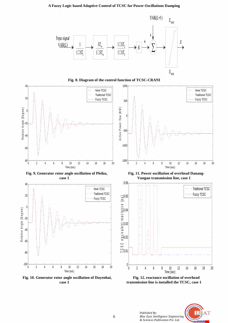
consists of 271 transmission lines and 162 transformer sub-stations at 220/110kV; the total generator output power is 31.504MW; the total system load is 30.539MW. The TCSC is installed at 500kV PLEIKU-CAUBONG transmission line with total length of 437km, the TCSC parameters and control function are given in Appendix and Fig. 8. To evaluate the usefulness of the proposed method for TCSC, assuming the scenarios are given shown in Table 2.
Table 2. Scenarios for studying Case
Three-phase
fault at Tripping of the transmission line
after 150ms 1 Phulam Phulam-Duchoa 2 Danang Danang-Docsoi 3 Hatinh Nhoquan-Hatinh
The calculations are based on the cases assumed in previous shown that there appeared two transmission lines with input signals of line active power for TCSC controller which given the best possibility for damping the power system oscillations. Two different cases are considered as follows:
(a) When three-phase fault occurs on overhead transmission lines at Southern Viet Nam power system, the selected input signal is the active power of Pleiku– Thanhmy overhead transmission line.
(b) When three-phase fault occurs on overhead transmission lines at Northern Viet Nam power system, the selected input signal is the active power of Caubong-Duchoa overhead transmission line. As illustrated in Fig. 7.
Table 3. Membership functions of fuzzy TCSC control model corresponding to rules
IF “ Three-phase fault occurred in Phulam-Duchoa transmission line ” THEN “TCSC is controlled as per rule no. 1”. IF “ Three-phase fault occurred in Danang-Docsoi transmission line ” THEN “TCSC is controlled as per rule no. 2”. IF “ Three-phase fault occurred in Nhoquan-Hatinh transmission line” THEN “TCSC is controlled as per rule no. 3”. .......
The adaptive controller of TCSC has been well established by studying various conditions and the proposed control rules. The membership function shown in the Table 3.
Control rules are as follows: Rule no.1: The control sample ( )1Z t was recorded
according to reactance oscillations of the conventional TCSC and the input signal of TCSC is an active power of Pleiku-Thanhmy transmission line.
Rule no.2: The control sample ( )2Z t was recorded
according to reactance oscillations of the conventional TCSC and the input signal of TCSC is an active power of Caubong-Duchoa transmission line.
Rule no.3: The control sample ( )3Z t was recorded
according to reactance oscillations of the conventional TCSC and the input signal of TCSC is an active power of Caubong-Duchoa transmission line.
B. Simulation results Some of contingency cases are taken in Table. 2 with three different conditions; namely, without TCSC, with the traditional TCSC and the proposed TCSC controller, Fig. 9 and Fig. 10 show the response time of the generator rotor angle oscillation of Pleiku, Duyenhai, Vinhtan, in case 1, respectively, respectively.
Fig. 11 depicts the response time of the power oscillation
International Journal of Engineering and Advanced Technology (IJEAT) ISSN: 2249 – 8958, Volume-4 Issue-4, April 2015
5 Published By: Blue Eyes Intelligence Engineering & Sciences Publication Pvt. Ltd.
of overhead Danang-Vungan transmission line in case 1. The response of the reactance is shown in Fig. 12. Fig. 13 and Fig. 14 also show the response time of the
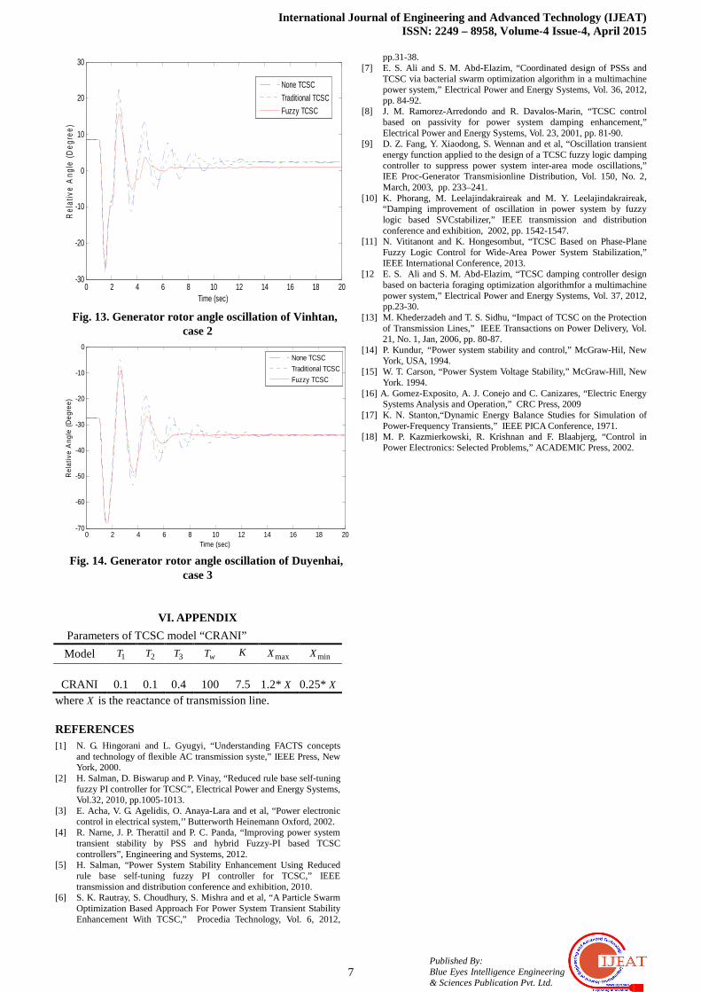
generator rotor angle oscillation of Vinhtan and Duyenha in case 2 and case 3, respectively
C. Analysis and discussion In order to investigate the impacts of the proposed controller, the simulation of transient stability in time domain is applied to both the traditional TCSC controller and the proposed FLBA-TCSC controller. The criterion for selection of optimized control model is based on the lowest time of damping the power system oscillations. In addition, the assessment of transient stability improvement of the power system with the TCSC controlled by Fuzzy is based on damping the oscillation of typical rotor angle oscillation, power oscillation, and the reactance oscillation of transmission line installed TCSC.
Fig. 9, Fig. 10, and Fig. 11 clearly show that the oscillation damping time of the power system equipped the proposed TCSC controller is about 7 to 8 seconds, while it is about 15 seconds for the system equipped with traditional TCSC controller. As observed in Fig. 12, due to applying the conventional TCSC controller, of which the input signal is much smaller than the FLBA one, the variations of reactance of Pleiku-Caubong transmission line during the transient period are very small, while it varies from lowest to highest about 6 seconds for the proposed TCSC controller. Hence, the observations indicate that the proposed TCSC controller is better.
Fig. 13 and Fig. 14 clearly show that the oscillation damping time of the power system that is equipped with proposed TCSC controller is about 6 to 7 seconds, while it is about 13 seconds for the system that is equipped with traditional TCSC controller.
V. CONCLUSION
The optimized control standard of TCSC based on fuzzy logic via the minimum total energy function method is proposed in this paper. An application of this method for “reduced practical system of Vietnamese power network” shows the effective damping performance. Operating the proposed TCSC controller receives the measured signals that are the variation of voltage angle between two buses installed the TCSC during transient state period in comparison with steady-state after removing the fault to control the reactance of transmission line via dependent function that relates to the various reactance values of transmission line, which are constructed by selecting the best cases that have been chosen by comparing the dynamic performance of conventional TCSC with different input line active power signals.
The simulation results show that the response speed of the generator rotor angle oscillation, power oscillation on the line, and reactance oscillation of overhead transmission are significantly improved, when using the proposed method.
120.1+j67.9
SonLaMongDuong
QuangNinh
ThangLong
HiepHoa
VietTriPitoongNhoQuan
HoaBinh
VungAng
PhoNoi
ThuongTin
TanDinh
VinhTanHaTinh
DaNang
DiLinh SongMay
TanUyen
PhuMy
DuyenHaiOMon
NhaBe
CauBong
Pleiku
MyTho
PhuLamDucHoa
DocSoi
ThanhMy
DakNong
511.4kV
510.4kV
999.6+j45.2
502.1kV
1476.6+j238.1
831+j115.2
500.8kV
626.4+j137.2
-93.2+j1.6730+j51.6
512.9kV
513.2kV
499.3kV
756.1+j62.31556.4+j210
492.3kV
509.4kV
488.8kV
491kV
844.4+j453.2
855+j201.2
272.9+j112.4872.8+j206.6
404.2+j149.1
492.4kV
646.9+j126.6
841.6+j30.3
508.8kV
503kV
881.2+j108.8
508.3kV
505.9kV
516.7kV
504kV
501.9kV
518kV
501.8kV
503.3kV
522kV
502.2kV
504.6kV
507.1kV
505.2kV502.7kV
513.8kV
652.8+j369.2
843.5+j212.3
371-j556.3
154.6-j326.5
1020.4+j389.81059.4+j353
512.2kV
582.6+ j124.6
1305.6+j189.6
457.4-j221.2
1443.8-j369.21197.6-j583.8
501.9kV
2158.8-j1040.4
1016.7-j243.2
825.5-j535.2
281+j191.7
1371.1-j731.2
709.6-j367.9
1144.6-j380.9
1028.2-j97.8
51.9+j74.1 -75.4+j231.4
319+j533.8
1215-j42.8
1022+ j345
1381.6+j653.4318.2+j272.2
282.2-j12
227.6-j72.5 120.1+j67.9
244.6+j8.2149.2-j31.4
335.2-j14.2
536.7-j145.4
1168.9-j47.2
855.6-j423.4
720.2+j88.8
565.7+j0.3
92.4-j55.6
481.2+j483.6
335+j169.8
1257.7+j299 76.4-j117.5
240.3+j169.1
600+j183.6
1860+j1080
1218-j23.2
1000+j132
600+j159.4
960.6+j470.3
495.5-j68.7
2400+j987.6
969.7-j162.4
553.4-j62
204+j271.6227+j30.5
564.2+j125
829.9+j264.1
1295-j297.3
Fig. 7. Practical system of Vietnamese power network.
A Fuzzy Logic based Adaptive Control of TCSC for Power Oscillations Damping
6 Published By: Blue Eyes Intelligence Engineering & Sciences Publication Pvt. Ltd.
1
1
1 ST+ 1w
w
ST
ST+2
3
1
1
ST
ST
++
K ∑
maxX
minX
X
Fig. 8. Diagram of the control function of TCSC-CRANI
0 2 4 6 8 10 12 14 16 18 20-80
-60
-40
-20
0
20
40
Time (sec)
Rel
ativ
e A
ngle
(D
egre
e)
None TCSC
Traditional TCSC
Fuzzy TCSC
Fig. 9. Generator rotor angle oscillation of Pleiku,
case 1
0 2 4 6 8 10 12 14 16 18 20-100
-80
-60
-40
-20
0
20
40
Time (sec)
Rel
ativ
e A
ngle
(D
egre
e)
None TCSC
Traditional TCSC
Fuzzy TCSC
Fig. 10. Generator rotor angle oscillation of Duyenhai,
case 1
0 2 4 6 8 10 12 14 16 18 20-1500
-1000
-500
0
500
1000
Time (sec)
Act
ive
Pow
er
flow
(M
W)
None TCSC
Traditional TCSC
Fuzzy TCSC
Fig. 11. Power oscillation of overhead Danang-
Vungan transmission line, case 1
0 2 4 6 8 10 12 14 16 18 200
0.01
0.02
0.03
0.04
0.05
0.06
Time (sec)
TC
SC
equ
ival
ent
reac
tanc
e (p
u)
Traditional TCSCFuzzy TCSC
Fig. 12. reactance oscillation of overhead
transmission line is installed the TCSC, case 1
International Journal of Engineering and Advanced Technology (IJEAT) ISSN: 2249 – 8958, Volume-4 Issue-4, April 2015
7 Published By: Blue Eyes Intelligence Engineering & Sciences Publication Pvt. Ltd.
0 2 4 6 8 10 12 14 16 18 20-30
-20
-10
0
10
20
30
Time (sec)
Rel
ativ
e A
ngle
(D
egre
e)
None TCSC
Traditional TCSC
Fuzzy TCSC
Fig. 13. Generator rotor angle oscillation of Vinhtan,
case 2
0 2 4 6 8 10 12 14 16 18 20-70
-60
-50
-40
-30
-20
-10
0
Time (sec)
Rel
ativ
e A
ngle
(D
egre
e)
None TCSC
Traditional TCSC
Fuzzy TCSC
Fig. 14. Generator rotor angle oscillation of Duyenhai,
case 3
VI. APPENDIX
Parameters of TCSC model “CRANI”
Model 1T 2T 3T wT K maxX minX
CRANI 0.1 0.1 0.4 100 7.5 1.2*X 0.25* X whereX is the reactance of transmission line.
REFERENCES [1] N. G. Hingorani and L. Gyugyi, “Understanding FACTS concepts
and technology of flexible AC transmission syste,” IEEE Press, New York, 2000.
[2] H. Salman, D. Biswarup and P. Vinay, “Reduced rule base self-tuning fuzzy PI controller for TCSC”, Electrical Power and Energy Systems, Vol.32, 2010, pp.1005-1013.
[3] E. Acha, V. G. Agelidis, O. Anaya-Lara and et al, “Power electronic control in electrical system,’’ Butterworth Heinemann Oxford, 2002.
[4] R. Narne, J. P. Therattil and P. C. Panda, “Improving power system transient stability by PSS and hybrid Fuzzy-PI based TCSC controllers”, Engineering and Systems, 2012.
[5] H. Salman, “Power System Stability Enhancement Using Reduced rule base self-tuning fuzzy PI controller for TCSC,” IEEE transmission and distribution conference and exhibition, 2010.
[6] S. K. Rautray, S. Choudhury, S. Mishra and et al, “A Particle Swarm Optimization Based Approach For Power System Transient Stability Enhancement With TCSC,” Procedia Technology, Vol. 6, 2012,
pp.31-38. [7] E. S. Ali and S. M. Abd-Elazim, “Coordinated design of PSSs and
TCSC via bacterial swarm optimization algorithm in a multimachine power system,” Electrical Power and Energy Systems, Vol. 36, 2012, pp. 84-92.
[8] J. M. Ramorez-Arredondo and R. Davalos-Marin, “TCSC control based on passivity for power system damping enhancement,” Electrical Power and Energy Systems, Vol. 23, 2001, pp. 81-90.
[9] D. Z. Fang, Y. Xiaodong, S. Wennan and et al, “Oscillation transient energy function applied to the design of a TCSC fuzzy logic damping controller to suppress power system inter-area mode oscillations,” IEE Proc-Generator Transmisionline Distribution, Vol. 150, No. 2, March, 2003, pp. 233–241.
[10] K. Phorang, M. Leelajindakraireak and M. Y. Leelajindakraireak, “Damping improvement of oscillation in power system by fuzzy logic based SVCstabilizer,” IEEE transmission and distribution conference and exhibition, 2002, pp. 1542-1547.
[11] N. Vititanont and K. Hongesombut, “TCSC Based on Phase-Plane Fuzzy Logic Control for Wide-Area Power System Stabilization,” IEEE International Conference, 2013.
[12 E. S. Ali and S. M. Abd-Elazim, “TCSC damping controller design based on bacteria foraging optimization algorithmfor a multimachine power system,” Electrical Power and Energy Systems, Vol. 37, 2012, pp.23-30.
[13] M. Khederzadeh and T. S. Sidhu, “Impact of TCSC on the Protection of Transmission Lines,” IEEE Transactions on Power Delivery, Vol. 21, No. 1, Jan, 2006, pp. 80-87.
[14] P. Kundur, “ Power system stability and control,” McGraw-Hil, New York, USA, 1994.
[15] W. T. Carson, “Power System Voltage Stability,” McGraw-Hill, New York. 1994.
[16] A. Gomez-Exposito, A. J. Conejo and C. Canizares, “Electric Energy Systems Analysis and Operation,” CRC Press, 2009
[17] K. N. Stanton,“Dynamic Energy Balance Studies for Simulation of Power-Frequency Transients,” IEEE PICA Conference, 1971.
[18] M. P. Kazmierkowski, R. Krishnan and F. Blaabjerg, “Control in Power Electronics: Selected Problems,” ACADEMIC Press, 2002.