Embed Size (px)
Citation preview

International Journal of Engineering Trends and Technology (IJETT) – Volume 54 Number 2 December 2017
ISSN: 2231-5381 http://www.ijettjournal.org Page 125
A Fuzzy Logic Based Algorithm for Electric
Power Network Management Chukwuagu .M.Ifeanyi Engr. Chukwuagu Monday Ifeanyi, Prof. T. C. Madueme
University of Nigeria Nsukka
The Department of Electrical engineering
ABSTRACT
This project work is aimed at developing an efficient
Algorithm for the management of Electric Power network using fuzzy logic. The fuzzy logic model
functions as a system operator in making decision for
load shedding and transfer switching. The new
developed algorithm will solve the problem of
inefficiencies associated with the conventional
methods for the management of the system. The new
technique uses the system data frequency variation,
load variation and voltage variation and the
experience of the system operators to formulate fuzzy
rules, which are then simulated using fuzzy logic
toolbox in MATLAB.
The fuzzy controller for the load shedding
management of power system, was modeled and
developed. Data collected from the New Haven
Nigerian switch gear was used to formulate the fuzzy
logic interference rules. Simulation results indicates
a remarkable improvement in the performance of the
load shedding management at the power plants.
Using the fuzzy controller the delay in load shedding
transfer switching was reduced from 600 s to 0.02316
s, representing 99.99% reduction in load shedding
transfer switching. The fuzzy logic controller achieved a load shedding energy efficiency of
90.57% as indicated in table 4.2 of this research
work.
INTRODUCTION
The MATLAB simulink fuzzy logic
controller tool box is used to model the load shedding
power logic management fuzzy logic controller. The
fuzzy logic membership function editor is used to create fuzzy linguistic variables as specified in This
Paper. The layout of the input/output of the controller
as illustrated within the simulink fuzzy logic FIS
editor is shown in figure 4.1b
Literature review
Fuzzy logic was a controversial subject
before 1960s, before then; there have been comments
on the issue. According to Plato said that there is
region of answers existing between true and false [3].
However, for many years prior to 1960, many
scholars at various universities gave many concepts
of fuzzy logic; even though their contributions were
fuzzy.
The concept of fuzzy logic (FL) was
conceived by Professor Lotfi Zadeh in 1960 as a way
of processing data by allowing partial membership.
In conventional logic, a statement is either true or
false, was formulated by Aristotle some years ago as
the law of “the excluded middle” .i.e. two valued
logic rather than crisp set membership or non-
membership.
Dr. Zadeh Lofti of university of California has since
then given many works, papers and tutorial on the subject [3-5].
Along the various developments on the
fuzzy logic, developing countries especially Asian
countries have also modeled many hardware for
fuzzy computations.
In fact the word fuzzy means vgueness or
unclearness, fuzzy logic hence is used to solve
problems whose answers and requirements are more
than simple Yes or No, true or False, on or off. Fuzzy
logic also takes care of the forbidden state of digital circuits (0.8V-2V) which is the main stream of
information technology.
Its applications are numerous; namely in
chemical process control, electrically controlled
machines, frequency converters manufacturing
industries, video machines, automobiles expert
systems and even in power system for heuristic
optimization.
It resembles human reasoning in its
approximation of information and uncertainty to
generate decisions. It was specially designed to mathematically generate decisions. It was specifically
designed to mathematically represent uncertainty and
vagueness and provide formalizing tools for dealing
with the imprecision to many problems. By contract,
traditional computing, demands precision down to
each bit. People do not require precise numerical
information input, and be capable of highly adaptive

International Journal of Engineering Trends and Technology (IJETT) – Volume 54 Number 2 December 2017
ISSN: 2231-5381 http://www.ijettjournal.org Page 126
control [6]. If feedback controllers could be
programmed to accept noisy, imprecise input, they
would be much more effective and perhaps easier to
implement. Since knowledge can be expressed in a
more natural way by using fuzzy sets, many
engineering and decision problems can be greatly simplified.
Fuzzy logic offers a better way of
representing reality or grading of thing in fuzzy logic
a statement is true to various degrees ranging from
completely true- through half-truth to completely
false. The idea of multi-valued logic gives a new
approach to the mathematics of thinking; it is a
change of paradigm to Aristotelian logic.
The computer tool used in expert system
development is “FLOPS” which means Fuzzy Logic
Production System. FLOPS is based on fuzzy system theory. Fuzzy sets, fuzzy logic and fuzzy numbers
[4]. The use of fuzzy mathematics gives FLOPS the
advantage to reason in terms of words such a small,
medium, fast slow and so on, rather than in terms of
numbers. Hence ambiguities and contradictions can
be easily handled and uncertainties pose no problems.
Fuzzy set theory implement classes or
groupings of data with boundaries that are not
sharply defined (i.e. fuzzy) any theory implementing
“crisp” definitions such as classical set theory, arithmetic, and programming may be “fuzzified” by
generating the concept of a crisp set to a fuzzy graph
theory and fuzzy data analysis, though the term fuzzy
logic is often used to describe them.
Truth of a statement is defined, as is correct.
Truth is measured numerically in most fuzzy systems
literatures, as ranging from zero (false) to one (true).
A typical fuzzy system consists of a rule-base,
membership functions and inference procedure.
Today fuzzy logic is found in a variety of control
applications including chemical process control,
manufacturing and in some consumer products like
washing machine, video cameras and automobiles.
Fuzzy Logic Based power Management: Below is a series of steps showing the
solution procedure followed in designing our scheme.
Step I: Choose appropriate input
conditions: Frequency, voltage and
load in this case
Step II: Determine the fuzzy knowledge
base and draw the membership
functions (for our design,
MATLAB codes are used).
Step III: Convert the input condition
variables to fuzzy sets
(fuzzification) Step IV: Design the fuzzy inference-
decision making (Rule base) and
simulate with appropriate program,
(like MATLAB).
Step V: Devise an appropriate
transformation of fuzzy logic
management action
(defuzzifications)
Step VI: Model the power management
controller using the MATLAB
SIMULINK fuzzy Logic toolbox. Step VII: Integrate the fuzzy logic power
management controller with the
MATLAB SIMULINK model of
the case study power system.
Step VIII: Carry out simulation and evaluate
the controller performance.
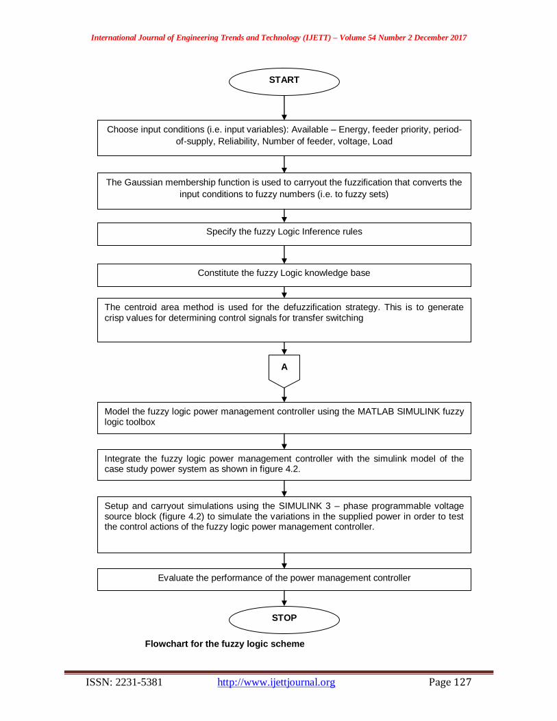
However, these steps were diligently applied here as
shown in the flowchart of figure 1.1
International Journal of Engineering Trends and Technology (IJETT) – Volume 54 Number 2 December 2017
ISSN: 2231-5381 http://www.ijettjournal.org Page 127
START
Choose input conditions (i.e. input variables): Available – Energy, feeder priority, period-
of-supply, Reliability, Number of feeder, voltage, Load
The Gaussian membership function is used to carryout the fuzzification that converts the
input conditions to fuzzy numbers (i.e. to fuzzy sets)
Specify the fuzzy Logic Inference rules
Constitute the fuzzy Logic knowledge base
The centroid area method is used for the defuzzification strategy. This is to generate crisp values for determining control signals for transfer switching
A
Model the fuzzy logic power management controller using the MATLAB SIMULINK fuzzy logic toolbox
Integrate the fuzzy logic power management controller with the simulink model of the case study power system as shown in figure 4.2.
Setup and carryout simulations using the SIMULINK 3 – phase programmable voltage source block (figure 4.2) to simulate the variations in the supplied power in order to test the control actions of the fuzzy logic power management controller.
Evaluate the performance of the power management controller
STOP
Flowchart for the fuzzy logic scheme

International Journal of Engineering Trends and Technology (IJETT) – Volume 54 Number 2 December 2017
ISSN: 2231-5381 http://www.ijettjournal.org Page 128
Modeling the Power Management fuzzy logic
controller inference rules Table 1.0 shows data obtained from power engineers
at New Haven Nigerian. Power switch is used for
formulating the fuzzy inference system. The fuzzy
logic controller linguistic variables are; 1. Available –energy
2. Feederpriority
3. Period-of-supply
4. Reliability
5. Number-of-feeders
The available energy is the total energy available
from the supply source as measured by simulink V-I
measurement block. The feed-priority is the priority
value (or weighting) assigned to feeders based on
power management policy of the power system
management. Period of supply is power sharing
supply duration allotted to different load centers in
situation of load shedding. Reliability is the
numerical rating assigned to different load centers by
power management decision to indicate feeders that
are likely to waste energy as a result of non-usage
resulting from high likelihood of fault. Number of feeders, based on power management decision,
determines load centers likely or not likely to be
supplied power on rotation basis, as a result of load
shedding decision.
The fuzzy sets are specified as HIGH and LOW.
Based on power management policy
currently being implemented at the case study power
system switchyard, the following fuzzy inference
rules are formulated for the power management fuzzy
controller.
1.0 Parameters for carrying out load shedding by power engineers of the New Haven Nigerian power switch
yard
Feeders Priority No ofFeeders Reliability Load
Kingsway II High 6 70% 17.50 MW
Kingsway I Low 5 70% 19.50 MW
Amechi road Low 1 30% because long distance tension
down on (low)
13.6MW
Ituku-Ozalla High 3 80% 15.10MW
Government house High 1 90% 8.0MW
Independence layout High 4 90% 10.6MW
New NNPC Low 2 30% 19.0MW
Thinkers Corner Low 4 90% 19.5MW
Emene Low 1 60% 8 MW
Fuzzy Inference rules
- If available-Energy is LOW and Feeder-priority is HIGH and period-of-supply is LOW THEN
supply is ON.
- If available-Energy is LOW AND Feeder-
priority is HIGH AND PERIOD-OF-Supply is
HIGH then Supply is OFF.
- If available-energy is LOW AND Feeder-priority
is LOW AND Number-of-Feeders is HIGH
AND Reliability is HIGH AND Period-of-supply
is low THEN supply is ON. - If available-Energy is LOW AND Feeder-
priority is LOW AND Number-of-Feeders is
HIGH AND Reliability is HIGH AND Period of-
supply is LOW THEN Supply is ON.
- If Available-Energy is LOW and Feeder-priority
is LOW And Number-of-feeders is LOW AND
Reliability is HIGH AND period-of-supply is
LOW THEN supply is OFF.
Source: Enugu Electricity Distribution Company [EEDC]
International Journal of Engineering Trends and Technology (IJETT) – Volume 54 Number 2 December 2017
ISSN: 2231-5381 http://www.ijettjournal.org Page 129
- If available-Energy is LOW AND Feeder-
priority is LOW and Number-of-feeders LOW
AND Reliability is LOW AND period-of-supply
is LOW THEN Supply is OFF.
- If available-Energy is LOW AND Feeder-
priority is LOW AND Number-of-feeder is HIGH AND Reliability is HIGH AND period-of-
supply is HIGH THEN Supply is OFF.
- If Available-Energy is LOW and Feeder-priority
is LOW AND Number-of-feeders HIGH AND
Reliability is HIGH and period-of-supply is
HIGH THEN Supply is OFF.
- If available-Energy is LOW AND feeder-priority
is LOW AND Number-of-feeders is LOW AND
Reliability is HIGH and period of Supply is
HIGH THEN supply is ON. - If Available-Energy is LOW AND Feeder-
priority is LOW and Number-of-feeders is LOW
AND Reliability is LOW AND period of supply
is HIGH THEN supply is ON.
- If Available-Energy is HIGH Supply is ON
33

International Journal of Engineering Trends and Technology (IJETT) – Volume 54 Number 2 December 2017
ISSN: 2231-5381 http://www.ijettjournal.org Page 130
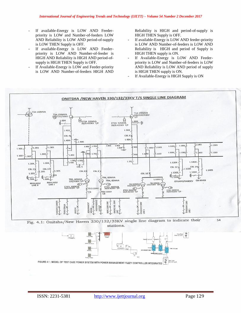
The MATLAB simulink model of the test
case power system with the power management fuzzy
logic controllers integrated is depicted figure 1.0.
As the source is set to be 145MW part of power
management load shedding is done to prevent the
power system from total collapse. The power management fuzzy controller
systematically sheds loads in the system in order to
systematically rotate power among the load center.
For the simulation set up, the load shedding is
simulated automatic fuzzy logic controlled transfer
switchgear operation.
The setup is to trip and reclose circuit breakers for
connecting and dropping loads on the feeders.
The fuzzy controller uses its inference rules
as modeled in chapter three to control the feeders
whose loads are dropped (OFF) or connected. The
fuzzy logic control is based on available power, the specified priorities of the number of feeders, the
reliability rating of the feeders and the duration of
having being supplied (period-of-supply).
Simulating Power Supply Variation and
Evaluating the Load Shedding Fuzzy
Controller
To be able to simulate variation in a case
where a demand would exceed generation, the
simulink 3 phase programmable voltage source block
is used. Referring to figure 1.0, the simulink 3-phase programmable voltage source block is used as the
variable energy source energizing the power system.
This block property in the simulink 3-phase
programmable voltage is used to set the variation
timing. The block is set to amplitude variation
timing, the variation type is step and the time
variation is set at intervals of 0.3 seconds. At step
times indicated, the 3-phase programmable power
source, based on the step function, varies the MVA
(MW) and MVAR of the power source downwards at
intervals. This simulates the drop in available energy.
As indicated in figure 1.0, the generator (variable
power source) is connected to the feeder network
through the simulink three-phase V-I measurement
block. This block provides the instrumentation feeds
(inputs) required by the discrete 3-phase PLL and the discrete 3-phase PLL-Driven positive sequence
Active of Reactive power block to dynamically
measure.
Evaluation is carried out to estimate average
reduction in load shedding transfer switching delay as
compared to the current manual method. Furthermore
the energy distribution is also evaluated.
At the set interval, the programmable power
source varies its power downwards by 25% descent
i.e following the trend 100%, 75%, 50% and 25%
corresponding to 145MW, 108.75MW, 72.5MW and 36.25MW the active (i.e in mega watts MW) and
reactive power supplied (available) to the network.
As indicated this measurement is fed as
input (available-energy) to the power management
fuzzy logic controller. The fuzzy logic controller uses
this value in its inference rule to determine the
feeders to drop or connected during the load shedding
operation. As indicated the required fuzzy linguistic
variables: feeder-priority, Number of-Feeders,
Period-of-Supply are input into the fuzzy logic controllers through the simulink cost and blocks.
Based on these variables, the fuzzy logic
controllers send trip signals to the circuit breakers to
trip loads (turn off) on the appropriate feeders.
At initialization of the programmable power source at
145MW, the profile of the active power excitation of
the generator is shown in figure 1.1
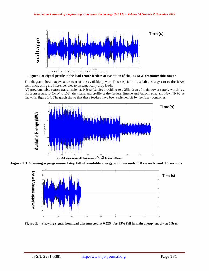
While the sample signal profiles at the feeders is shown in Figure 1.2
Figure 1.1: Power profile of the 145 MW generators used in the simulationstudy
FIGURE 4.2 MODEL OF TEST CASE POWER SYSTEM WITH POWER MANAGEMENT FUZZY CONTROLLER INTEGRATED
41
Time(s)
International Journal of Engineering Trends and Technology (IJETT) – Volume 54 Number 2 December 2017
ISSN: 2231-5381 http://www.ijettjournal.org Page 131
The diagram shows stepwise descent of the available power. This step fall in available energy causes the fuzzy
controller, using the inference rules to systematically drop loads.
AT programmable source transmission at 0.5sec (carries providing to a 25% drop of main power supply which is a
fall from around 145MW to 108), the signal and profile of the feeders: Emene and Amechi road and New NNPC as shown in figure 1.4. The graph shows that these feeders have been switched off by the fuzzy controller.
Figure 1.4: showing signal from load disconnected at 0.5254 for 25% fall in main energy supply at 0.5sec.
Figure 1.2: Signal profile at the load centre feeders at excitation of the 145 MW programmable power
source
Figure 1.3: Showing a programmed step fall of available energy at 0.5 seconds, 0.8 seconds, and 1.1 seconds.
Time(s)
Time(s)
Time (s)
Availa
ble
energ
y (M
W)
International Journal of Engineering Trends and Technology (IJETT) – Volume 54 Number 2 December 2017
ISSN: 2231-5381 http://www.ijettjournal.org Page 132
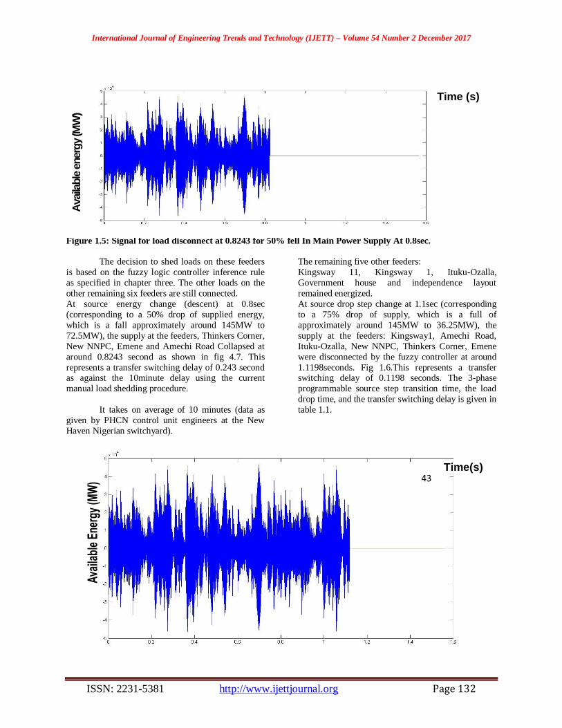
Figure 1.5: Signal for load disconnect at 0.8243 for 50% fell In Main Power Supply At 0.8sec.
The decision to shed loads on these feeders
is based on the fuzzy logic controller inference rule
as specified in chapter three. The other loads on the
other remaining six feeders are still connected.
At source energy change (descent) at 0.8sec
(corresponding to a 50% drop of supplied energy,
which is a fall approximately around 145MW to
72.5MW), the supply at the feeders, Thinkers Corner,
New NNPC, Emene and Amechi Road Collapsed at
around 0.8243 second as shown in fig 4.7. This
represents a transfer switching delay of 0.243 second as against the 10minute delay using the current
manual load shedding procedure.
It takes on average of 10 minutes (data as
given by PHCN control unit engineers at the New
Haven Nigerian switchyard).
The remaining five other feeders:
Kingsway 11, Kingsway 1, Ituku-Ozalla,
Government house and independence layout
remained energized.
At source drop step change at 1.1sec (corresponding
to a 75% drop of supply, which is a full of
approximately around 145MW to 36.25MW), the
supply at the feeders: Kingsway1, Amechi Road,
Ituku-Ozalla, New NNPC, Thinkers Corner, Emene
were disconnected by the fuzzy controller at around
1.1198seconds. Fig 1.6.This represents a transfer switching delay of 0.1198 seconds. The 3-phase
programmable source step transition time, the load
drop time, and the transfer switching delay is given in
table 1.1.
Figure 1.6: Showing signal for disconnect at about 1.1198sec for 75% power drop at 1.1sec.
Time (s)
Availa
ble
energ
y (M
W)
44
Time(s) 43

International Journal of Engineering Trends and Technology (IJETT) – Volume 54 Number 2 December 2017
ISSN: 2231-5381 http://www.ijettjournal.org Page 133
The feeders connected, the available power and demanded power at connected feeders at various switching
transfer time are given in table 1.2. For table 1.2.
Table 1.1: Reduction in load shedding transfer switching delay by the fuzzy logic controller
Source supply Step Transition time
(seconds)
Load drop Time (secs) Transfer switching (delay)time
0.5 0.5254 0.0254
0.8 0.8243 0.0243
1.1 1.1198 0.0198
𝐴𝑣𝑒𝑟𝑎𝑔𝑒 𝑑𝑒𝑙𝑎𝑦 = 0.0254 + 0.0243 + 0.0198
3
𝐴𝑣𝑒𝑟𝑎𝑔𝑒 𝑑𝑒𝑙𝑎𝑦 =0.0695
3
= 0.02316𝑠𝑒𝑐 Based on the current manually load shedding transfer switching at the New Haven switch yard, it takes (according to
one of the staff) an average of 10minutes to carry out the operation.
This means reduction in load shedding transfer switching delay from 600sec to 0.02316sec. This represents a
99.99% reduction in transfer switching delay.
Table 1.2 using parameter values for the estimation of the controller load shedding energy efficiency
Supply fall
transition time (sec)
Connected feeders Demanded power
(MW)
available power
(supplied MW)
losses (MW)
0.5 Kingsway II
Kingsway I
ItukuOzalla
Government house
Independence layout
Thinkers Corner
90.2 108.75 18.55
0.8 Kingsway II
Kingsway I
ItukuOzalla
Government house
Independence layout
70.7 72.5 1.8
1.1 Kingsway II Government house
Independence layout
36.1 36.25 0.15
TOTAL 197 217.5 20.5
Some amount of energy would be wasted as a result of supply offer over shoot. This depends of the controllers
computation of available energy at any time as against demanded energy on the connected feeders (i.e. connect load
centers, that is the load centers that were not disconnected by the fuzzy controller). Hence evaluating the power
management efficiency is in order.
Efficiency = WorkOutput
Workinput× 100%
= EnergyUsed
EnergySupplied× 100%
In this power management control case,
Efficiency = Energy used by connected feeder
Energy supplied× 100%
Referring to table 1.2

International Journal of Engineering Trends and Technology (IJETT) – Volume 54 Number 2 December 2017
ISSN: 2231-5381 http://www.ijettjournal.org Page 134
Efficiency = Energy demanded by Connected feeders x 100%
Energy supplied
197
217.5 × 100%
= 90.57%
The power management fuzzy controllers achieved a load shedding efficiency of 90.57%.
Conclusion Fuzzy Logic based method was used in the
development of power management Algorithm. The
approach was effective in implementing a simple
fuzzy procedure to solve a problem that required
rigorous methods when the conventional approach is
used. Only the system or network frequency or voltage
is sufficient to implement this technique. The system
simulation shows that the proposed approach is able to
make decision and serve as logic for system stability,
which acts to protect or save the network.
REFERENCES [1] L.A. Zadeh; “Fuzzy sets, Fuzzy genetic system and outline of
a new approach to the analysis of complex system”. University
of California, USA, pp 20 – 33, November, 1965.
[2] G.J. Klir and T.A. Folger; “Fuzzy sets Uncertainty and
Information” Prentice Hall, Engle wood Cliffs, N.J., pp 34 –
35, February, 1988.
[3] C.C. Lee, “Fuzzy Logic in Control Systems” IEEE Trans. On
Systems, Man and Cybernetics, SMC, Vol.20; pp. 35,40,
March, 1990.
[4] D.K. Steven, “Fuzzy Logic an Introduction part 2” (ONLINE)
available www.search Seattlerobotics.org ,pp 45 – 46,
February, 2006.
[5] K. Kishan, M.R. Akbarzadeh, k. Kumbla, E. Tunstel, A.T
John’s, “Adaptaive Neuro- fuzzy logic controller ona digital
signal processor’’, University of New Mexico, USA,pp 50 –
51, April, 1992.
[6] P. korthmann, “Design of fuzzy logic controller by meansof
fuzzy models’’, Ruhr –University, Bochum, pp 54 – 67,
September, 1990.
[7] J.Shing Roger Jang, C. Tsai Son, “Neuro – Fuzzy Modeling
and Control,” proceedings of the IEEE, pp 4 – 5, March, 1995.