Embed Size (px)
Citation preview
1
A HAND BOOK FOR
DC MACHINES LAB
Electrical & Electronics Engineering
Department
2
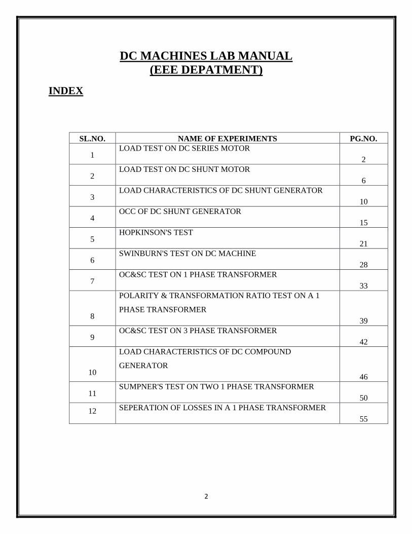
DC MACHINES LAB MANUAL
(EEE DEPATMENT)
INDEX
SL.NO. NAME OF EXPERIMENTS PG.NO.
1 LOAD TEST ON DC SERIES MOTOR
2
2 LOAD TEST ON DC SHUNT MOTOR
6
3 LOAD CHARACTERISTICS OF DC SHUNT GENERATOR
10
4 OCC OF DC SHUNT GENERATOR
15
5 HOPKINSON'S TEST
21
6 SWINBURN'S TEST ON DC MACHINE
28
7 OC&SC TEST ON 1 PHASE TRANSFORMER
33
8
POLARITY & TRANSFORMATION RATIO TEST ON A 1
PHASE TRANSFORMER
39
9 OC&SC TEST ON 3 PHASE TRANSFORMER
42
10
LOAD CHARACTERISTICS OF DC COMPOUND
GENERATOR
46
11 SUMPNER'S TEST ON TWO 1 PHASE TRANSFORMER
50
12 SEPERATION OF LOSSES IN A 1 PHASE TRANSFORMER
55
3
EX. NO. : 1 DATE :
LOAD TEST ON DC SERIES MOTOR AIM:
1) To conduct load test on DC series motor and to determine the efficiency using
mechanical loading arrangement
2) To draw the following characteristics curves
Torque Vs Armature current (electrical characteristics)
Speed Vs Armature current
Speed Vs Torque (Mechanical characteristics)
Performance curve
APPARATUS REQUIRED:
Sl no Name of Apparatus Type Specification Qty
1 Ammeter
2 Voltmeter
3 Rheostat
4 Tachometer
MACHINES DETAILS:
THEORY:
Ina series motor the field winding is connected in series with the armature .The
field current and the armature current are the same.Series motor is a variable speed
motor. If the mechanical load on the motor increases, the armature current also
increases. Hence the flux in a series motor increases with increase in armature
current.
4
NαEb/ɸ
Taα ɸ Ia
ɸ α Ia , so Taα Ia2
ie, Starting torque of a series motor will be very high .
ifNαEb/ɸ ,WhenIa is very small speed become dangerously high, so a series motor
should never be started without somemechanical load on it, if there is no
mechanical load at the time of starting it may develop excessive speed and get
damaged due to heavy centrifugal force produced.
The load test is conducted by applying a spring balance load to brake drum of
machine. By tightening the belt over the pulley different load can be applied. The
spring balance reading S1 and S2 are noted and the effective radius ‘r’ of the
pulley is measured.
If N is the speed of motor, then Torque developed T= (S1-S2)rg Nm
The output power can be calculated as P=2πNT/60 Watts.
Efficiency of the motor=output power/input power.
PRECAUTIONS:
1. DC Series motor should notstart on no load condition.
2. Brake drum should be cooled with water when it is under load.
PROCEDURE:
Connections are made as per the circuit diagram.
The precautions checked before starting the experiment.
A 220 V Dc supply is given to the circuit using two point starter.
Varying the load (Take readings up to rated current of the machine) by
tightening/releasing the belt over the pulley, the meter readings, spring
balance reading and speed are noted. After bring the load to initial position,
switch of the supply.
5
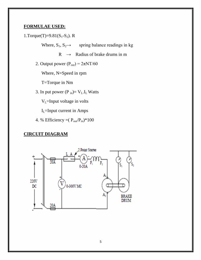
FORMULAE USED:
1.Torque(T)=9.81(S1-S2). R
Where, S1, S2→ spring balance readings in kg
R → Radius of brake drums in m
2. Output power (Pout) = 2πNT/60
Where, N=Speed in rpm
T=Torque in Nm
3. In put power (P in)= VL.IL Watts
VL=Input voltage in volts
IL=Input current in Amps
4. % Efficiency =( Pout/Pin)*100
CIRCUIT DIAGRAM
6
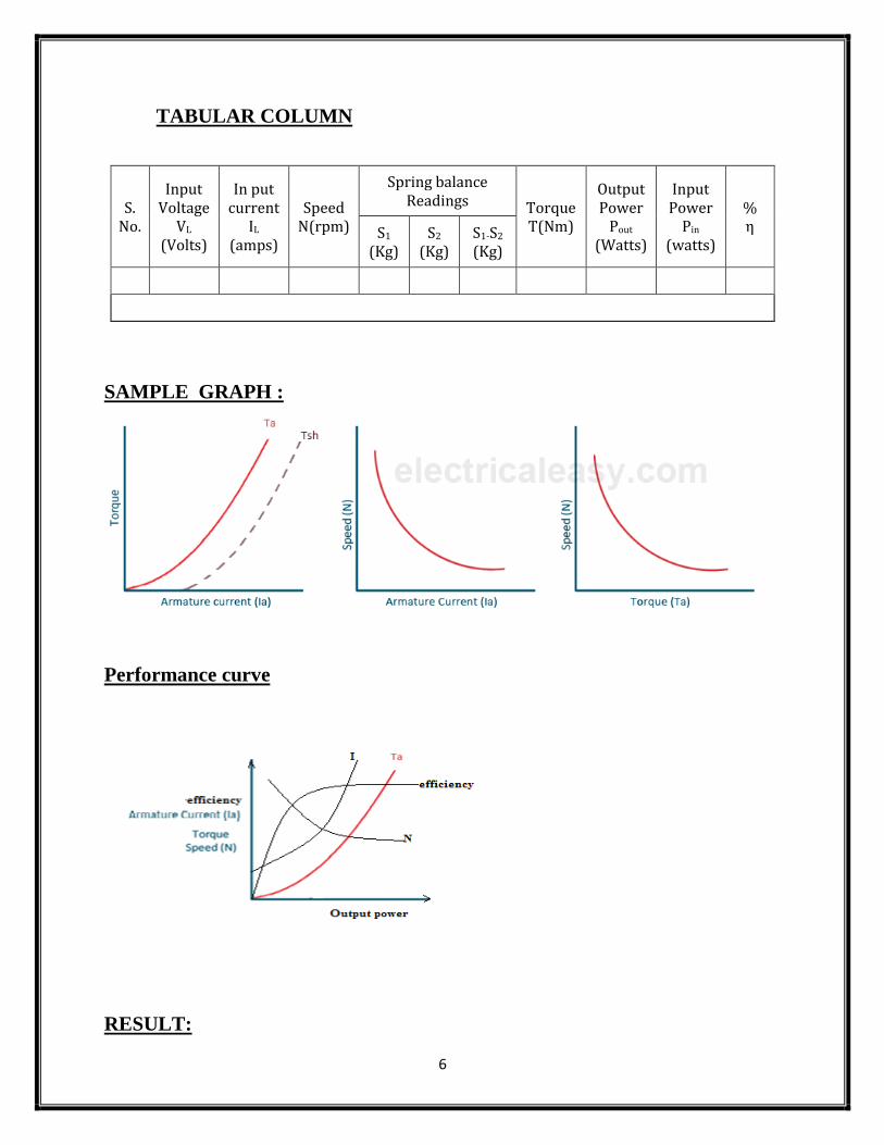
TABULAR COLUMN
S. No.
Input Voltage
VL (Volts)
In put current
IL (amps)
Speed N(rpm)
Spring balance Readings Torque
T(Nm)
Output Power
Pout (Watts)
Input Power
Pin (watts)
% η S1
(Kg) S2
(Kg) S1-S2
(Kg)
SAMPLE GRAPH :
Performance curve
RESULT:
7
EX. NO. :2
DATE :
LOAD TEST ON DC SHUNT MOTOR
AIM:
To conduct load test on DC shunt motor and to determine the efficiency using
mechanical loading arrangement
To Draw the following characteristics curves
Torque Vs Armature current (electrical characteristics)
Speed Vs Armature current
Speed Vs Torque (Mechanical characteristics)
Performance curve
APPARATUS REQUIRED:
Sl no Name of Apparatus Type Specification Qty
1 Ammeter
2 Voltmeter
3 Rheostat
4 Tachometer
MACHINES DETAILS:
THEORY:
Ina shunt motor the field winding is connected in parallel with the armature .The
field current and the armature current are not same. Shunt field windings are
having large number of turns of wire having high resistance. So shunt field current
is relatively small compared with the armature current. Applied voltage andRsh of
a shunt motor are constant, so field current Ish also will be constant.
8
Ish=V/Rsh
Hence, the flux in a shunt motor is constant.
N α Eb/ɸ
As ɸ is constant, speed of shunt motor will be constant.
Taα ɸ Ia
ɸ is constant, so Taα Ia
Sostarting torque of a shunt motor islow.
The load test is conducted by applying a spring balance load to brake drum of
machine. By tightening the belt over the pulley different load can be applied. The
spring balance reading S1 and S2 are noted and the effective radius ‘r’ of the
pulley is measured.
If N is the speed of motor, then Torque developed T= (S1-S2)rgNm
The output power can be calculated as 2πNT/60 Watts
Efficiency of the motor=output power/input power.
PRECAUTIONS:
1. DC shunt motor should be started and stopped under no load condition.
2. Field rheostat should be kept in the minimum position.
3. Brake drum should be cooled with water when it is under load.
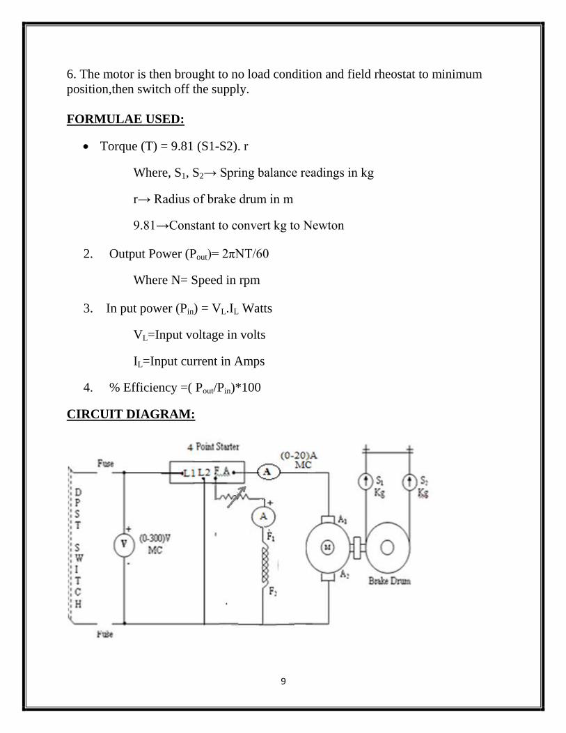
PROCEDURE:
1. Connections are made as per the circuit diagram
2. After checking the no load condition and minimum field rheostat position starter
resistance is gradually removed.
3. The motor is brought to its rated speed by adjusting the field rheostat.
4. Ammeter, Voltmeter readings, speed and spring balance readings are noted
under no loadcondition.
5. The load is then added to the motor gradually and for each load, voltmeter,
ammeter, springbalance readings and speed of the motor are noted(Take readings
up to rated current of the machine).
9
6. The motor is then brought to no load condition and field rheostat to minimum
position,then switch off the supply.
FORMULAE USED:
Torque (T) = 9.81 (S1-S2). r
Where, S1, S2→ Spring balance readings in kg
r→ Radius of brake drum in m
9.81→Constant to convert kg to Newton
2. Output Power (Pout)= 2πNT/60
Where N= Speed in rpm
3. In put power (Pin) = VL.IL Watts
VL=Input voltage in volts
IL=Input current in Amps
4. % Efficiency =( Pout/Pin)*100
CIRCUIT DIAGRAM:
10
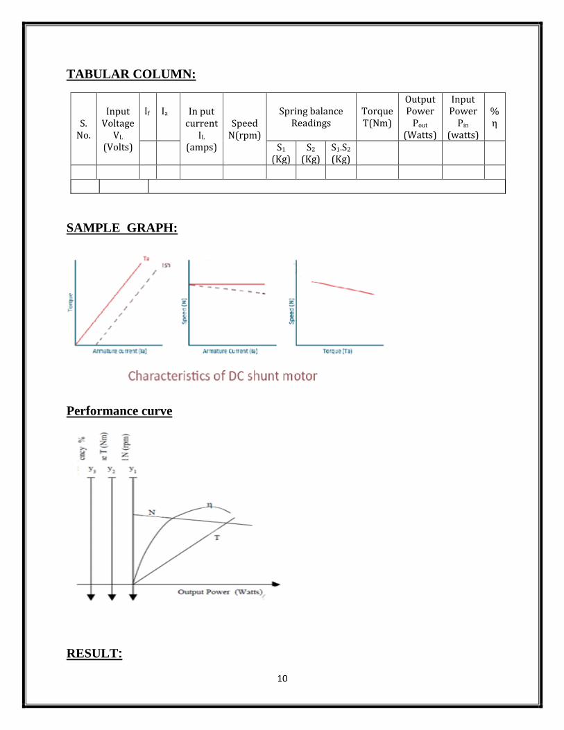
TABULAR COLUMN:
S. No.
Input Voltage
VL (Volts)
If
Ia In put
current IL
(amps)
Speed N(rpm)
Spring balance Readings
Torque T(Nm)
Output Power
Pout (Watts)
Input Power
Pin (watts)
% η
S1
(Kg) S2
(Kg) S1-S2
(Kg)
SAMPLE GRAPH:
Performance curve
RESULT:
11
EX. NO. :3 DATE :
LOAD CHARACTERISTICS OF DC SHUNT GENERATOR
AIM:
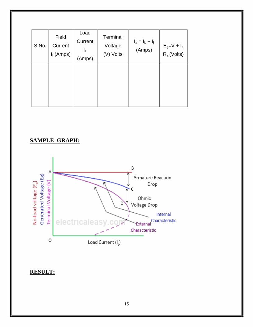
To obtain internal and external characteristics of DC shunt generator.
APPARATUS REQUIRED:
S.No. Apparatus Specification Quantity
1 Ammeter
2 Voltmeter
3 Rheostats
4 Loading Rheostat
5 Tachometer
MACHINES DETAILS:
THEORY:
In a shunt generator, the field winding is connected in parallel with the armature
winding so that terminal voltage of the generator is applied across it.The shunt
field winding has many turns of fine wire having high resistance. Therefore, only a
part of armature current flows through shunt field winding and the rest flows
through the load.
For a DC Shunt GeneratorE0=V + IaRa
Ia= IL + Ish
Ish= V/Rsh
12
Where, E0 is the induced emf
V is the terminal voltage
Ia is the armature current
IL is the load current
Internal characteristics: it is the plot of the induced voltage E with armature
current. Drop in voltage is due to armature reaction which increases with increase
in load current.
External characteristics: It is the plot of terminal voltage with load current at
constant field resistance and speed. As the load on the machine is varied the
terminal voltage drops it is due to
1) The drop in voltage across the armature resistance, IaRa drop.
2) Armature reaction the air gap flux decreases which will reduced the
induced emf.
3) The drop in terminal voltage due to 1 & 2 results in decrease field
current which further reduces the induced emf.
PRECAUTIONS:
The field rheostat of motor should be at minimum position.
The field rheostat of generator should be at maximum position.
No load should be connected to generator at the time of starting and
stopping.
PROCEDURE:
Connections are made as per the circuit diagram.
After checking minimum position of DC shunt motor field rheostat and
maximum position of DC shunt generator field rheostat, DPST switch is
closed and starting resistance is gradually removed.
13
Adjust the motor field rheostat to adjust the speed to rated speed of
generator.
Under no load condition, Ammeter and Voltmeter readings are noted, after
bringing the voltage to rated voltage by adjusting the field rheostat of
generator.
Load is varied gradually until rated current and for each load, voltmeter and
ammeter readings are noted.
Then the generator is unloaded and the field rheostat of DC shunt generator
is brought to maximum position and the field rheostat of DC shunt motor to
minimum position, DPST switch is opened.
FORMULAE:
Eg = V + Ia Ra (Volts)
Ia = IL + If (Amps)
Eg : Generated emf in Volts
V : Terminal Voltage in Volts
Ia : Armature Current in Amps
IL : Line Current in Amps
If : Field Current in Amps
Ra : Armature Resistance in Ohms
14
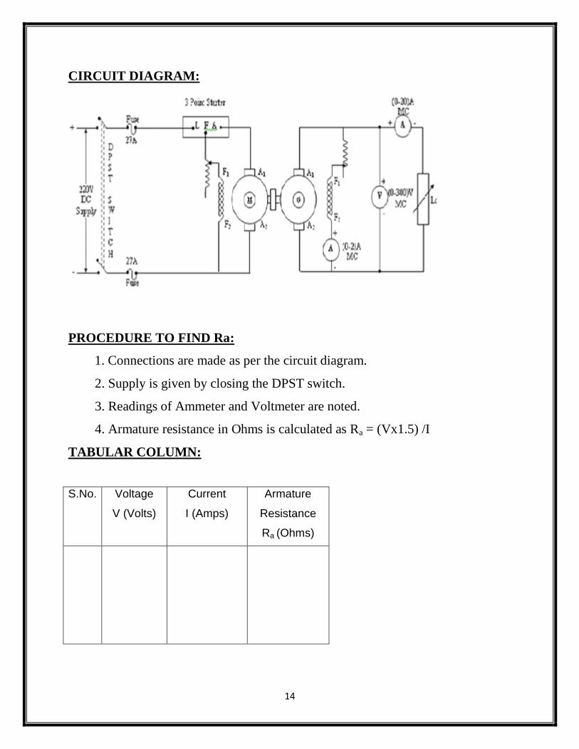
CIRCUIT DIAGRAM:
PROCEDURE TO FIND Ra:
1. Connections are made as per the circuit diagram.
2. Supply is given by closing the DPST switch.
3. Readings of Ammeter and Voltmeter are noted.
4. Armature resistance in Ohms is calculated as Ra = (Vx1.5) /I
TABULAR COLUMN:
S.No. Voltage
V (Volts)
Current
I (Amps)
Armature
Resistance
Ra (Ohms)
15
S.No.
Field
Current
If (Amps)
Load
Current
IL
(Amps)
Terminal
Voltage
(V) Volts
Ia = IL + If
(Amps)
Eg=V + Ia
Ra (Volts)
SAMPLE GRAPH:
RESULT:
16
EX. NO. :4
DATE :
OPEN CIRCUIT CHARACTERISTICS OF DC SHUNT GENERATOR
AIM:
1) Toplot the OCC of a given DC Generator at rated speed & to find the critical
speed & critical resistance.
2) To plot the OCC at 3/4 th
rated speed.
3) To find the value of additional resistance to be added in field circuit in order to
make it as critical field resistance.
APPARATOUS REQUIRED:
S.No. Apparatus Range Type Quantity
1 Ammeter
2 Voltmeter
3 Rheostats
4 SPST Switch
5 Tachometer
MACHINES DETAILS:
THEORY :
The open circuit characteristic gives the variation of generated voltage(E) with
field current (If) at a constant speed.
17
E=ZɸN/60. P/A
ie, E α ɸN
When speed is constant, generated voltage is proportional to field flux. When the
field current is zero,a small residual flux is present in the machine and a small
voltage is generated even when field current is zero. As the field current is
increased the voltage increases linearly with field current. At some values of If,
magnetic circuit starts getting saturated. In saturation region, voltage increases
only slightly with increase in field current. So the generated voltage is directly
proportional to speed.
OCC of a generator shows the relation between the no load generated emfin the
generator & the field current in armature. If when the generator is driven at
constant rated speed, the field current is varied by adjusting the resistance
connected in the field. The field current is increased in suitable steps starting from
zero and the corresponding value of induced emf, E0is noted. The curve does not
start from the origin but from the point above the Y-axis, slightly above the origin.
This is due to the residual magnetism in the poles of generator at low value of field
current.
If we are given O.C.C. of a generator at a constant speed N1, then we can easily
draw the O.C.C. at any other constant speed N2.
18
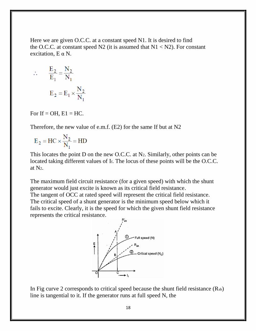
Here we are given O.C.C. at a constant speed N1. It is desired to find
the O.C.C. at constant speed N2 (it is assumed that N1 < N2). For constant
excitation, E α N.
For If = OH, E1 = HC.
Therefore, the new value of e.m.f. (E2) for the same If but at N2
This locates the point D on the new O.C.C. at N2. Similarly, other points can be
located taking different values of If. The locus of these points will be the O.C.C.
at N2.
The maximum field circuit resistance (for a given speed) with which the shunt
generator would just excite is known as its critical field resistance.
The tangent of OCC at rated speed will represent the critical field resistance.
The critical speed of a shunt generator is the minimum speed below which it
fails to excite. Clearly, it is the speed for which the given shunt field resistance
represents the critical resistance.
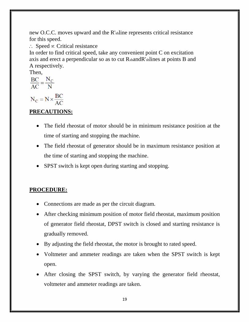
In Fig curve 2 corresponds to critical speed because the shunt field resistance (Rsh)
line is tangential to it. If the generator runs at full speed N, the
19
new O.C.C. moves upward and the R'shline represents critical resistance
for this speed.
Speed Critical resistance
In order to find critical speed, take any convenient point C on excitation
axis and erect a perpendicular so as to cut RshandR'shlines at points B and
A respectively.
Then,
PRECAUTIONS:
The field rheostat of motor should be in minimum resistance position at the
time of starting and stopping the machine.
The field rheostat of generator should be in maximum resistance position at
the time of starting and stopping the machine.
SPST switch is kept open during starting and stopping.
PROCEDURE:
Connections are made as per the circuit diagram.
After checking minimum position of motor field rheostat, maximum position
of generator field rheostat, DPST switch is closed and starting resistance is
gradually removed.
By adjusting the field rheostat, the motor is brought to rated speed.
Voltmeter and ammeter readings are taken when the SPST switch is kept
open.
After closing the SPST switch, by varying the generator field rheostat,
voltmeter and ammeter readings are taken.
20
Field current is varied till generated voltage reaches 125% of the rated
voltage.
After bringing the generator rheostat to maximum position, field rheostat of
motor to minimum position, SPST switch is opened and DPST switch is
opened.
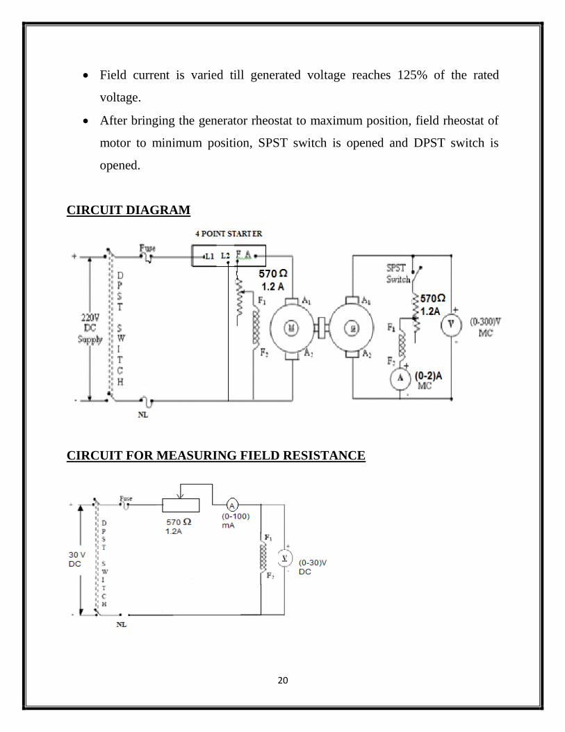
CIRCUIT DIAGRAM
CIRCUIT FOR MEASURING FIELD RESISTANCE
21
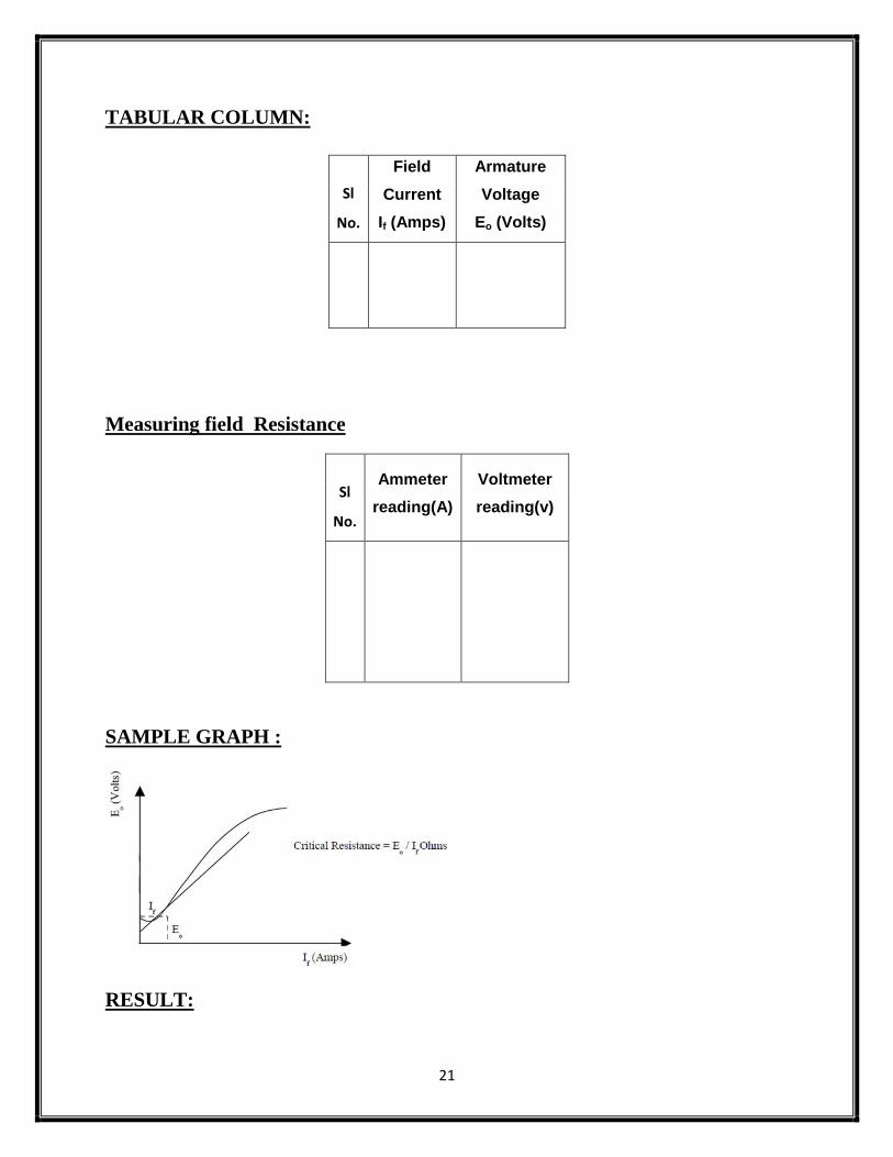
TABULAR COLUMN:
Sl
No.
Field
Current
If (Amps)
Armature
Voltage
Eo (Volts)
Measuring field Resistance
Sl
No.
Ammeter
reading(A)
Voltmeter
reading(v)
SAMPLE GRAPH :
RESULT:
22
EX. NO.:5
DATE :
HOPKINSON’S TEST
AIM:
To conduct Hopkinton’s test on a pair of identical DC machines to pre-determine
the efficiency of the machine as generator and as motor and to plot the efficiency
curve.
APPARATUS REQUIRED:
MACHINES DETAILS:
THEORY :
This test is called regenerative test or back to back test which can be carried out on
two identical d.c. machines mechanically coupled to each other. Thus the full load
test can be carried out on two identical shunt machines without wasting their
outputs. One of the machines is made to act as a motor while the other as a
generator. The mechanical output obtained from the motor drives the generator.
Sl
no Name of Apparatus Type Specification Qty
1 Ammeter
2 Voltmeter
3 Rheostat
4 Tachometer
23
Electrical output from the generator supplies part of input to the motor. The motor
is connected to the supply mains only to compensate for losses .In the absence of
losses, the motor-generator set would have run without any external power supply.
But due to losses, the generator output is not sufficient to drive the motor. Thus
motor takes current from the supply to account for losses.
The switch S is kept open.The first machine connected to supply will act as motor.
Thus second machinewhich is acting as generator will act as a load to the first
machine. The speed of motor is adjusted to normal value with the help of the field
rheostat. The voltmeter reading is observed. The voltage of the generator is
adjusted by its field rheostat so that voltmeter reading is zero. This will indicate
that the generator voltage is having same magnitude and polarity of that of supply
voltage. This will prevent heavy circulating current flowing in the local loop of
armatures on closing the switch. Now switch S is closed. The two machines can be
put into any load by adjusting their field rheostats. The generator current I2 can be
adjusted to any value by increasing the excitation of generator or by reducing the
excitation of motor. The various reading shown by different ammeters are noted
for further calculations.
The input to the motor is nothing but the output of the generator and small
power taken from supply. The mechanical output given by motor after supplying
losses will in turn drive the generator.
PRECAUTIONS:
1. The field rheostat of the motor should be in the minimum position at the time of
starting and stopping the machine.
2. The field rheostat of the generator should be in the maximum position at the time
of starting and stopping the machine.
24
3. SPST switch should be kept open at the time of starting and stopping the
machine.
PROCEDURE:
1. Connections aremade as per the circuit diagram.
2. After checking the minimum position of field rheostat of motor, maximum
position of field rheostat of generator, opening of SPST switch, DPST switch is closed
and starting resistance is gradually removed.
3. The motor is brought to its rated speed by adjusting the field rheostat of the
motor.
4. The voltmeter V1 is made to read zero by adjusting field rheostat of generator
and SPST switch is closed.
5. By adjusting field rheostats of motor and generator, various Ammeter readings,
voltmeter readings are noted. (Care should be taken to avoid current exceeding
rated values of motor and generator)
6. The rheostats and SPST switch are brought to their original positions and DPST
switch is opened
25
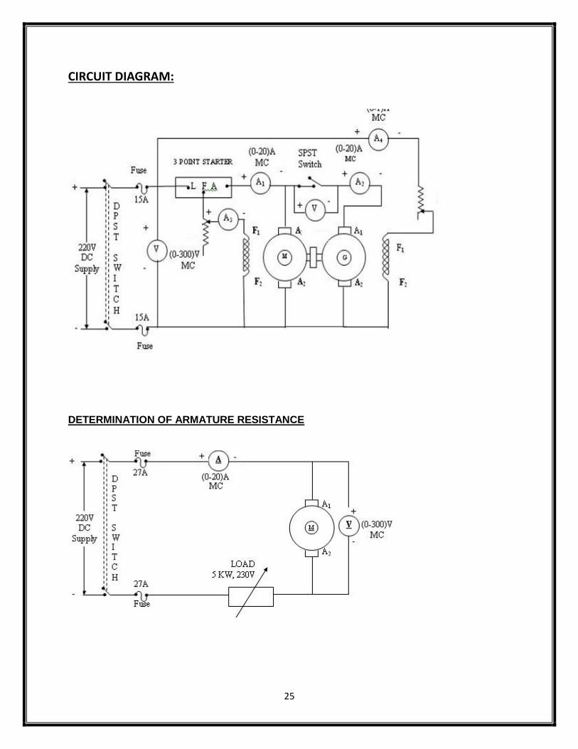
CIRCUIT DIAGRAM:
DETERMINATION OF ARMATURE RESISTANCE
26
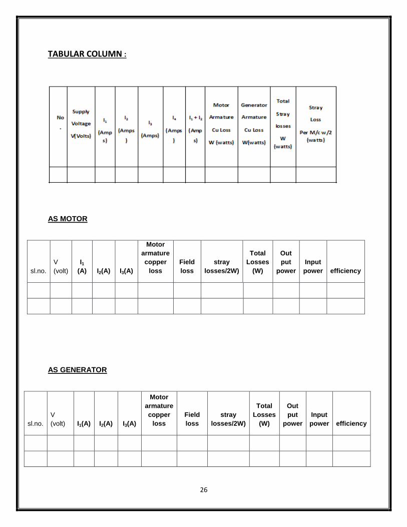
TABULAR COLUMN :
AS MOTOR
sl.no.
V
(volt)
I1
(A) I2(A) I3(A)
Motor
armature
copper
loss
Field
loss
stray
losses/2W)
Total
Losses
(W)
Out
put
power
Input
power efficiency
AS GENERATOR
sl.no.
V
(volt) I1(A) I2(A) I3(A)
Motor
armature
copper
loss
Field
loss
stray
losses/2W)
Total
Losses
(W)
Out
put
power
Input
power efficiency
27
FORMULAE USED
Input Power = VI1watts
Motor armature cu loss = (I1+ I2)2 Ra watts
Generator armature cu loss = I22 Ra watts
Total Stray losses W = V I1 - (I1+I2)2 Ra + I22 Ra watts.
Stray loss per machine = W/2 watts.
AS MOTOR:
Input Power = Armature input + Shunt field input
= (I1+ I2) V + I3V = (I1+I2+I3) V
Total Losses = Armature Cu loss + Field loss + stray loss
= (I1 + I2)2 Ra + VI3 + W/2 watts
Efficiency % = Input power – Total Losses / input power
AS GENERATOR:
Output Power = VI2 watts
Total Losses = Armature Cu loss+ Field Loss + Stray loss
= I22 Ra + VI4 + W/2 watts
Efficiency % = Output power / Output Power+ Total Losses
28
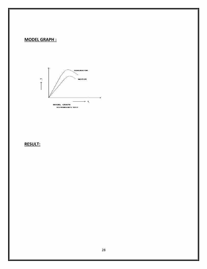
MODEL GRAPH :
RESULT:
29
EX. NO. :6 DATE :
SWINBURNE’STEST
AIM:
To conduct Swinburne’s test on DC machine to determine efficiency when
working as generator and motor without actually loading the machine. Also plot
efficiency curves.
APPARATU REQUIRED:
Sl.
No
Name of the
Apparatus Range Type Quantity
MACHINE DETAILS:
THEORY :
The power that a dc machine receives is called input power & power it gives out is
called output power.
ie ,The efficiency of a dc machine,
Efficiency= output/input
Output=Input-Losses & Input=Output+ Losses
Swinburne’s test is a no load test conducted on a DC Machine which run as motor
at noload& losses of the machine are determined. Once the losses of machine are
known,its efficiency at any desired load can be determined in advance. This test
only applicable in machines that flux is constant at all loads. In this test, the dc
shunt machine is run as a motor on no load with supply voltage adjusted to rated
voltage. The speed of the motor is adjusted to rated speed with the help of field
rheostat.
Let
30
IL → No load line current
Ia0 → No load armature current
V → input voltage
Ish → Shunt field current
I a02. Ra → No load armature copper loss
At no load condition,
No load input power (Pin) =V.IL
No load input current(Iao) =IL-Ish
No load power input to the armature =V.Iao =V.(IL-Ish)
Since the output of the motor is zero,the no load input power to the armature
supplies iron loss,frictionloss,windage loss & armature copper loss.
No load armature loss (WCU) = (Iao)2.Ra
Constant loss (Wc)= Input to motor-Armature copper loss
=Pin-Wcu
=V.IL-Iao2Ra
=V.IL-(IL-Ish)2.Ra
EFFICIENCY OF MOTOR
Input power (Pout) = VIL
Ia+Ish = IL
Armature copper loss (Wcu)
Constant loss(Wc )
Input=Output +Losses
V(Ia+Ish)=Output+Wc+Ia2Ra
Ia2Ra-VIa+Output+Wc-VIsh=0
Ia =V± V2− 4Ra(output +Wc− VIsh)/ 2Ra
Wcu = Ia2Ra=(IL-Ish)
2Ra
Wc =Pin-Wcu
=Pin -(IL-Ish)2Ra
31
Total losses = Wcu+Wc
%Efficiency = Pout/Pin * 100
= (Pin-total losses)/Pin* 100
EFFICIENCY OF GENERATOR
Output power (P out) = VIL
Armature current (Ia) = IL+Ish
Armature copper loss (Wc) = Ia2Ra=(IL+Ish)
2Ra
Total losses = Wcu+Wc=(IL+Ish)2Ra+Wc
%Efficiency = Pout/Pin * 100
=Pout/(Pout+total losses) * 100
PRECAUTIONS: The field rheostat should be in the minimum position at the time of starting and
stopping the motor
PROCEDURE:
1. Connections are made as per the circuit diagram.
2. After checking the minimum position of field rheostat, DPST switch is closed
and starting resistance is gradually removed.
3. By adjusting the field rheostat, the machine is brought to its rated speed.
4. The armature current, field current and voltage readings are noted.
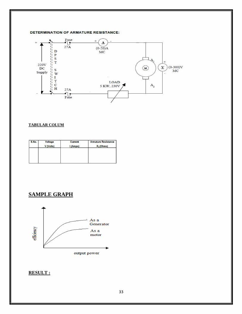
5. The field rheostat is then brought to minimum position DPST switch is opened. PROCEDURE FOR DETERMINING THE RESISTANCE:
1. Connections are made as per the circuit diagram.
2. Supply is given by closing the DPST switch.
3. Readings of Ammeter and Voltmeter are noted.
4. Armature resistance in Ohms is calculated as Ra = (Vx1.5) /I
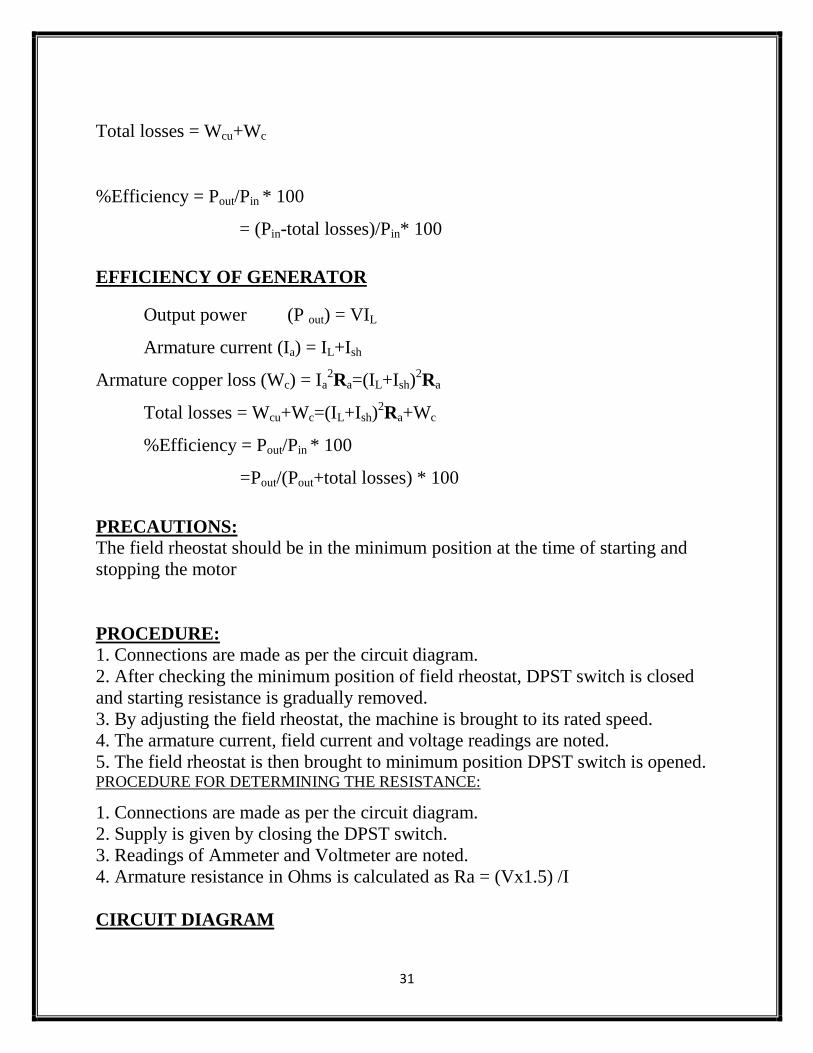
CIRCUIT DIAGRAM
32
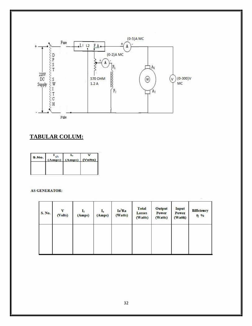
TABULAR COLUM:
33
TABULAR COLUM
SAMPLE GRAPH
RESULT :
34
EX. NO. :7
DATE :
O.C AND S.C TESTS ON SINGLE PHASE TRANSFORMER
AIM:
To conduct open circuit and short circuit tests on the given 2.5KVA
transformerand predetermine the following:-
1. Equivalent circuit as referred to low voltage side
2. Equivalent circuit a referred to high voltage side
3. Efficiency curve at 0.8 pf lag and lead
4. Regulation at unity, lagging and leading power factors
APPARATUS REQUIRED:
Sl no Name of Apparatus Type Specification Qty
1 Ammeter
2 Voltmeter
3 Rheostat
4 Tachometer
MACHINES DETAILS
THEORY:
Open Circuit test
This test is usually conducted on the low voltage side side of the transformer. It is
conducted to determine the core loss(iron loss or no load loss). The low voltage
side of the transformer is supplied at rated voltage with the high voltage side left
open. The current, voltage and power on the input side is noted. Since the no-load
primary current is small(2-10% of the rated current) the copper losses in the
primary winding can be neglected and the power loss read by the wattmeter is the
core loss of the transformer. Since the flux linking with the core is constant at all
loads, the core loss remains same for all loads. The parameters R0 and X0 (the
shunt branch) are determined using this test.
35
Input power, W0 = V0I0cos0
cos0 = P0 / V0 I0
Iw = I0cos0, I= I0sin0
R0 = V0/ Iw , X0= V0 / I
V2/V1 (HV/LV)
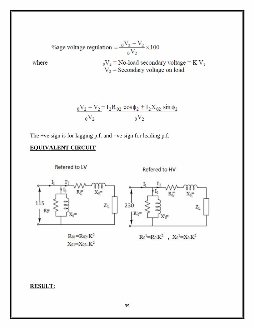
R01=R0K
2 , X0
1=X0K
2
Iw1=Iw.K ,I
I
Short Circuit test
The short circuit test is conducted to determine the full load copper loss and the
equivalentresistance and leakage reactance referred to the winding in which the test
is conducted. The test is conducted on the high voltage side with the low voltage
side short circuited by a thick conductor. A low voltage just enough to circulate the
rated current of the transformer is supplied to the transformer. The voltage supplied
is usually only 5-10% of the normal supply voltage and so the flux linking with the
core is small. Thus core losses can be neglected and the wattmeter reading gives
the full load Cu loss of the transformer
WSC=Isc2R02,
R02=WSC/Isc2
Z02=Vsc/Isc
X02=
R01=R02/ K2
X01=X02/.K2
I2=KVA*100/V2
36
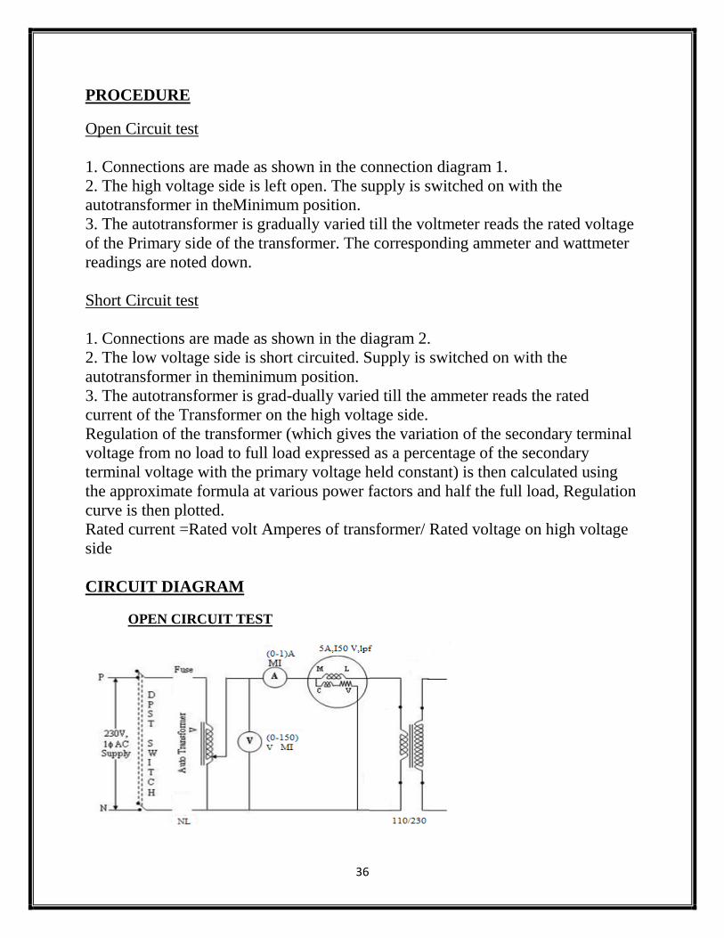
PROCEDURE
Open Circuit test
1. Connections are made as shown in the connection diagram 1.
2. The high voltage side is left open. The supply is switched on with the
autotransformer in theMinimum position.
3. The autotransformer is gradually varied till the voltmeter reads the rated voltage
of the Primary side of the transformer. The corresponding ammeter and wattmeter
readings are noted down.
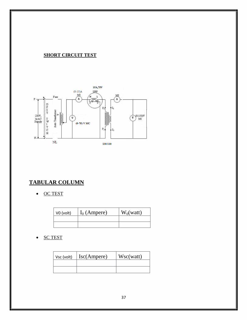
Short Circuit test
1. Connections are made as shown in the diagram 2.
2. The low voltage side is short circuited. Supply is switched on with the
autotransformer in theminimum position.
3. The autotransformer is grad-dually varied till the ammeter reads the rated
current of the Transformer on the high voltage side.
Regulation of the transformer (which gives the variation of the secondary terminal
voltage from no load to full load expressed as a percentage of the secondary
terminal voltage with the primary voltage held constant) is then calculated using
the approximate formula at various power factors and half the full load, Regulation
curve is then plotted.
Rated current =Rated volt Amperes of transformer/ Rated voltage on high voltage
side
CIRCUIT DIAGRAM
OPEN CIRCUIT TEST
37
SHORT CIRCUIT TEST
TABULAR COLUMN
OC TEST
V0 (volt) I0 (Ampere) W0(watt)
SC TEST
Vsc (volt) Isc(Ampere) Wsc(watt)
38
REGULATION
Lagging power factor Leading power factor
sl.no. cosɸ Regulation sl.no. cosɸ Regulation
Efficiency from Transformer Tests F.L. Iron loss =W o from open-circuit test
F.L. Cu loss =Wc from short-circuit test
Total F.L. losses = Wo+WSC
We can now find the full-load efficiency of the transformer at any p.f. without
actually loading the transformer.
Also for any load equal to x x full-load,
Note that iron loss remains the same at all loads.
Voltage Regulation The voltage regulation of a transformer is the arithmetic difference (not phasor
difference) between the no-load secondary voltage (0V2) and the secondary
voltage V2 on load expressed as percentage of no-load voltage i.e.
39
The +ve sign is for lagging p.f. and ve sign for leading p.f.
EQUIVALENT CIRCUIT
RESULT:
40
EX. NO. :8
DATE :
POLARITY & TRANSFORMATION RATIO TEST ON SINGLE
PHASE TRANSFORMER
AIM:
To check the polarity of single phase transformer & find the transformation ratio.
APPARATUS REQUIRED:
Sl no Name of Apparatus Type Specification Qty
1 Ammeter
2 Voltmeter
3 Rheostat
4 Tachometer
MACHINES DETAILS:
THEORY:
Transformation Test
The transformation ratio ‘K’ is equal to the number of turns in the secondary
divided by the number of turns in the primary OR it is the ratio of induced emf in
the secondary to induced emf in the primary.
ie, K=N2/N1 =E2/E1
41
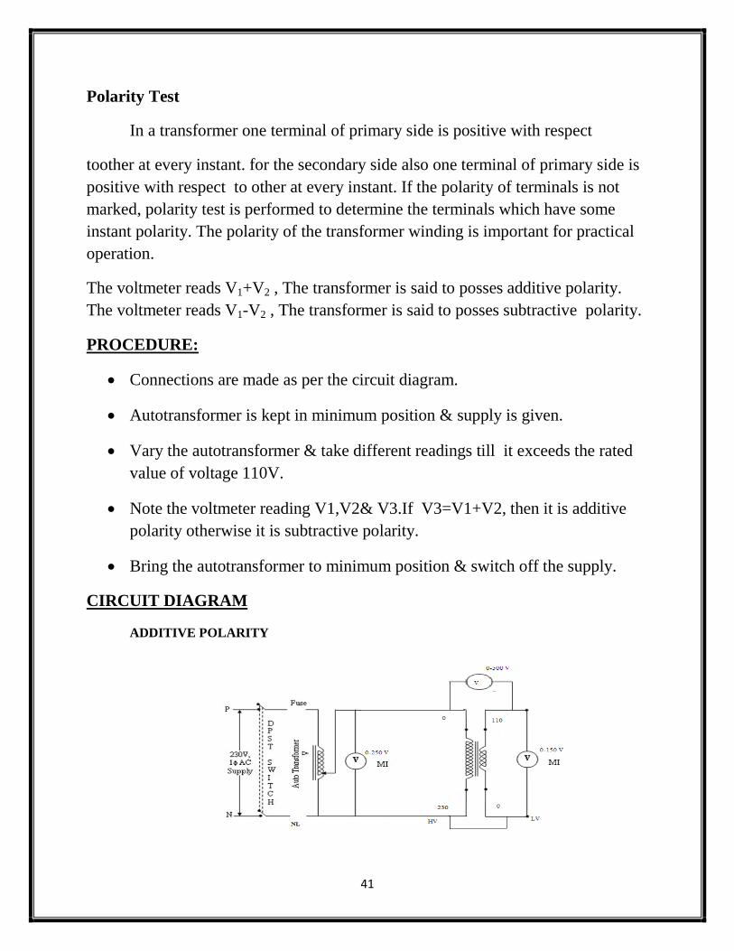
Polarity Test
In a transformer one terminal of primary side is positive with respect
toother at every instant. for the secondary side also one terminal of primary side is
positive with respect to other at every instant. If the polarity of terminals is not
marked, polarity test is performed to determine the terminals which have some
instant polarity. The polarity of the transformer winding is important for practical
operation.
The voltmeter reads V1+V2 , The transformer is said to posses additive polarity.
The voltmeter reads V1-V2 , The transformer is said to posses subtractive polarity.
PROCEDURE:
Connections are made as per the circuit diagram.
Autotransformer is kept in minimum position & supply is given.
Vary the autotransformer & take different readings till it exceeds the rated
value of voltage 110V.
Note the voltmeter reading V1,V2& V3.If V3=V1+V2, then it is additive
polarity otherwise it is subtractive polarity.
Bring the autotransformer to minimum position & switch off the supply.
CIRCUIT DIAGRAM
ADDITIVE POLARITY
42
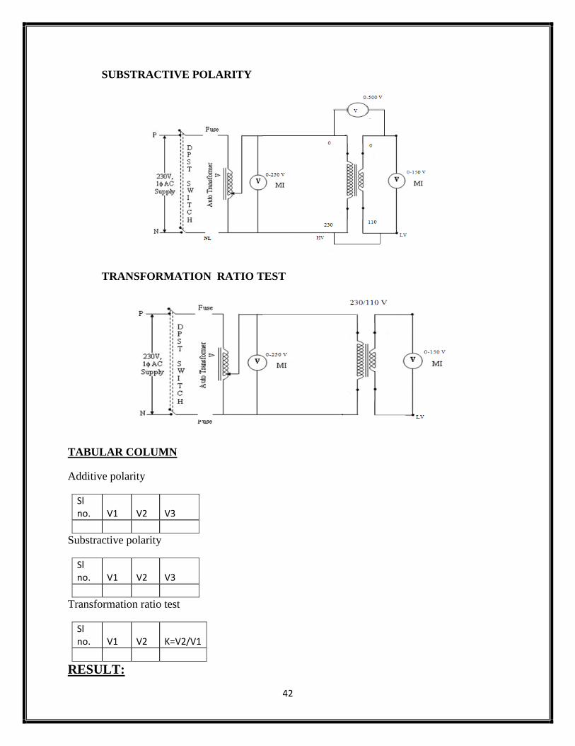
SUBSTRACTIVE POLARITY
TRANSFORMATION RATIO TEST
TABULAR COLUMN
Additive polarity
Sl no. V1 V2 V3
Substractive polarity
Sl no. V1 V2 V3
Transformation ratio test
Sl no. V1 V2 K=V2/V1
RESULT:
43
EX. NO. :9
DATE :
OC & SC TEST ON THREE PHASE TRANSFORMER
AIM:
1)To determine the perphase equivalent circuit parameter referred to LV side &
HV side.
2) To predetermine the efficiency & regulation for different load condition and to
plot the curves.
APPARATOUS REQUIRED
THEORY:
A three-phase transformer can be constructed by having three primary and three
Secondary windings on a common magnetic circuit. The three single-phase core
type transformers, each with windings (primary and secondary) on only one leg
Have their unwound legs combined to provide a path for the returning flux. The
Primaries as well as secondaries may be connected in star or delta. If the primary is
energized from a 3-phase supply, the central limb (i.e., unwound limb) carries the
fluxes produced by the 3-phase primary windings. Since the Since the phasor sum
of three primary currents at any instant is zero, the sum of three fluxes passing
through the central limb must be zero. Hence no flux exists in the central limb and
it may, therefore, be eliminated. This modification gives a three leg core type 3-
phase transformer. In this case, any two legs will act as a return path for the flux in
the third leg. For example, if flux is in one leg at some instant, then flux is /2 in
the opposite direction through the other two legs at the same instant. All the
connections of a 3-phase transformer are made inside the case and for delta-
Sl. No.
Name of the Apparatus
Range Type Quantity
44
connected winding three leads are brought out while for star connected winding
four leads are brought out.
PROCEDURE:
OC TEST :
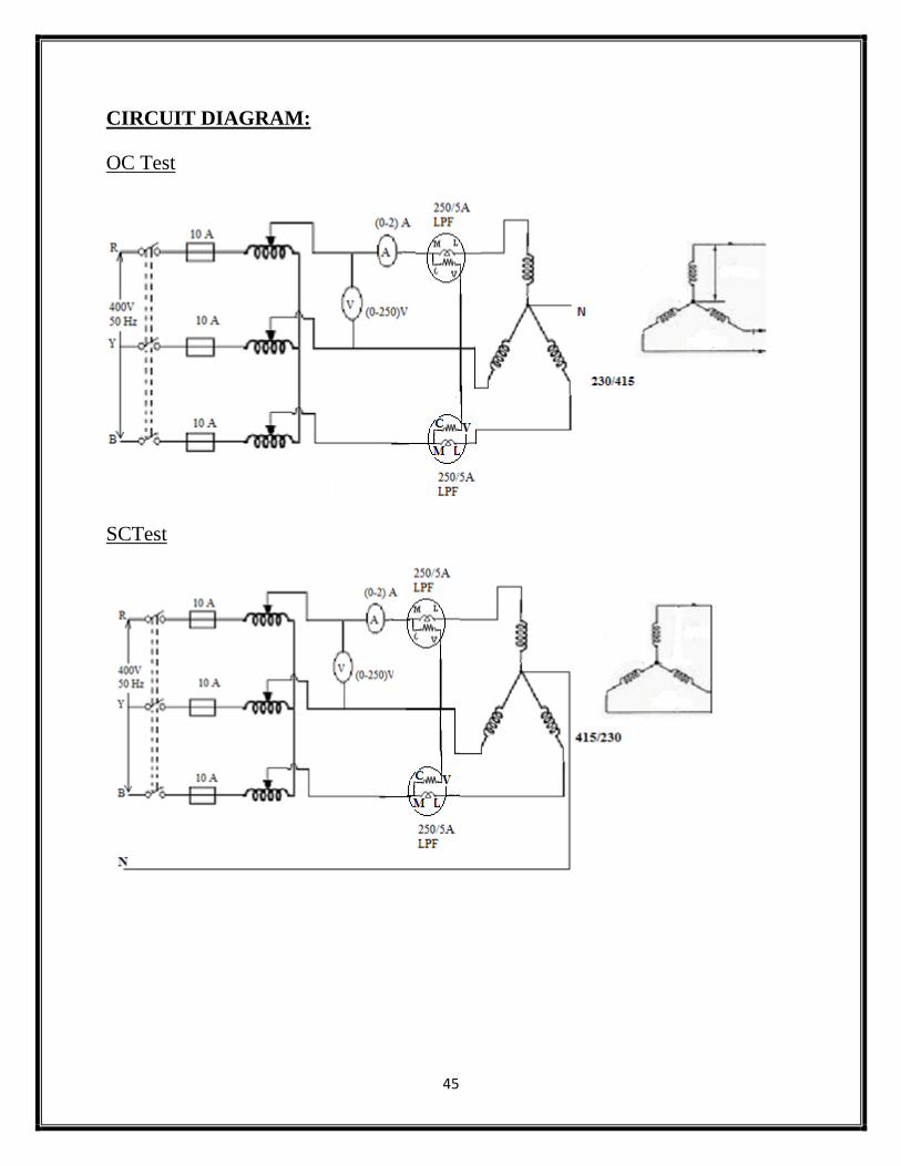
1. Connections are made as per the circuit diagram.
2. Three phase auto transformer is placed in minimum position & supply is
given by DPST switch is closed and starting resistance is gradually removed.
3. Adjust the autotransformer to get the rated voltage which is read by
voltmeter which is equal to 230V.
4. Note the readings, sum of of the readings of two wattmeter’s to give core
loss.
5. set the auto transformer to its initial position & switch off the supply.
SC TEST:
1. Connections are made as per the circuit diagram.
2. Three phase auto transformer is placed in minimum position & supply is
given by DPST switch is closed and starting resistance is gradually removed.
3. Adjust the autotransformer to get the rated current which is read by
Ammeter in high voltage side which is equal to rated current.
4. Note the readings, sum of of the readings of two wattmeter’s to give copper
loss.
5. set the auto transformer to its initial position & switch off the supply.
45
CIRCUIT DIAGRAM:
OC Test
SCTest
46
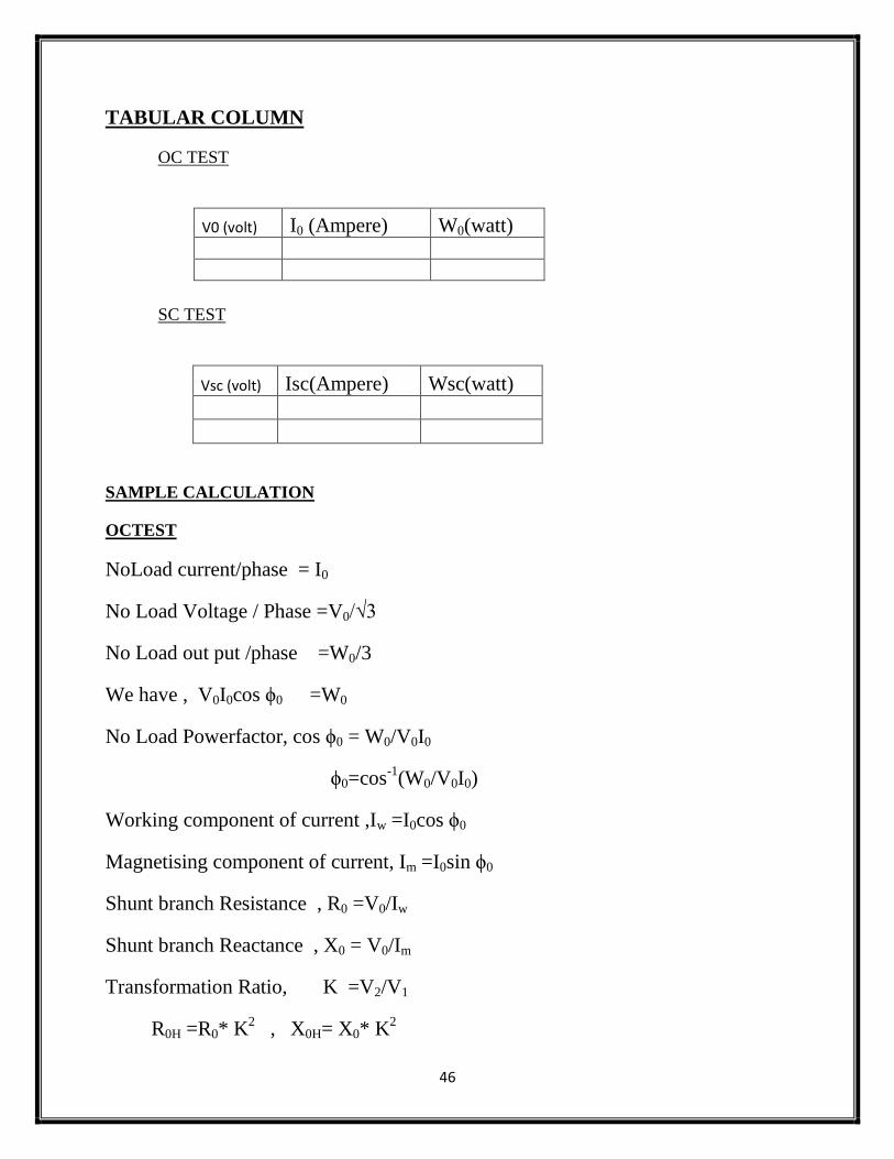
TABULAR COLUMN
OC TEST
V0 (volt) I0 (Ampere) W0(watt)
SC TEST
Vsc (volt) Isc(Ampere) Wsc(watt)
SAMPLE CALCULATION
OCTEST
NoLoad current/phase = I0
No Load Voltage / Phase =V0/√3
No Load out put /phase =W0/3
We have , V0I0cos ϕ0 =W0
No Load Powerfactor, cos ϕ0 = W0/V0I0
ϕ0=cos-1
(W0/V0I0)
Working component of current ,Iw =I0cos ϕ0
Magnetising component of current, Im =I0sin ϕ0
Shunt branch Resistance , R0 =V0/Iw
Shunt branch Reactance , X0 = V0/Im
Transformation Ratio, K =V2/V1
R0H =R0* K2 , X0H= X0* K
2
47
SC TEST
SC Load current/phase = Isc
SC Load Voltage / Phase =Vsc/√3
SC out put /phase =Wsc/3
We have ,VscIsccosϕsc =Wsc
No Load Powerfactor, cosϕsc = Wsc/VscIsc
Φsc=cos-1
(Wsc/Vsc
Z02 =VSC/Isc
R02 =Wsc /Isc2
X02=√(Z022-R02
2)
Transformation Ratio, K =V2/V1
R0L=R02/ K2
X0L =X02/ K2
Result
48
EX. NO. :10
DATE :
LOAD CHARACTERISTICS OF DC COMPOUND GENERATOR
AIM:
To conduct a load test on the given dc compound generator & plot its internal &
external characteristics when working in cumulative & differential mode.
APPARATOUS REQUIRED:
MACHINE DETAILS:
THEORY:
The compounding of a machine is done by adding a few coils in series with the
armature coil circuit of a shunt machine. Compound generator, both series and
shunt excitation are combined. The shunt winding can be connected either across
the armature only (short-shunt connection S) or across armature plus series field
(long-shunt connection G). The compound generator can be cumulatively
compounded or differentially compounded generator.
When a compound generator has its series field flux aiding its shunt
field flux, the machine is said to be cumulative compound. When the series field is
connected in reverse so that its field flux opposes the shunt field flux, the
generator is then differential compound. The easiest way to build up voltage in a
compound generator is to start under no load conditions. At no load, only the shunt
field is effective. When no-load voltage build up is achieved, the generator is
loaded. If under load, the voltage rises, the series field connection is cumulative. If
the voltage drops significantly, the connection is differential compound.
Sl. No.
Name of the Apparatus
Range Type Quantity
49
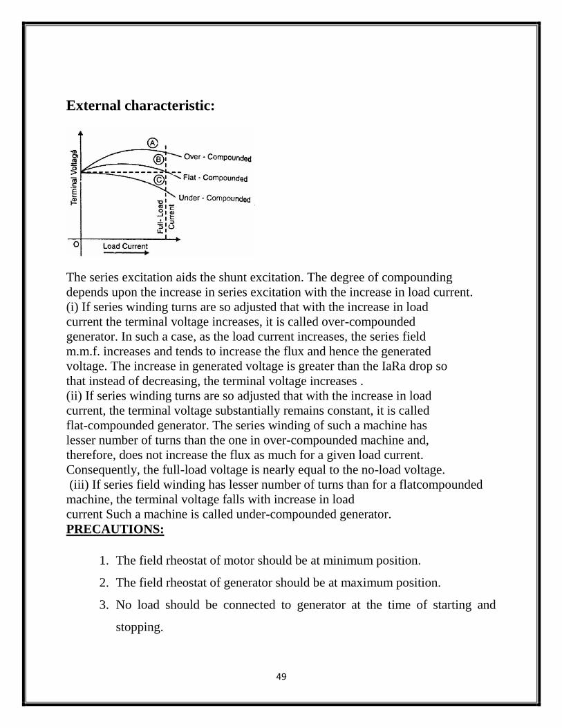
External characteristic:
The series excitation aids the shunt excitation. The degree of compounding
depends upon the increase in series excitation with the increase in load current.
(i) If series winding turns are so adjusted that with the increase in load
current the terminal voltage increases, it is called over-compounded
generator. In such a case, as the load current increases, the series field
m.m.f. increases and tends to increase the flux and hence the generated
voltage. The increase in generated voltage is greater than the IaRa drop so
that instead of decreasing, the terminal voltage increases .
(ii) If series winding turns are so adjusted that with the increase in load
current, the terminal voltage substantially remains constant, it is called
flat-compounded generator. The series winding of such a machine has
lesser number of turns than the one in over-compounded machine and,
therefore, does not increase the flux as much for a given load current.
Consequently, the full-load voltage is nearly equal to the no-load voltage.
(iii) If series field winding has lesser number of turns than for a flatcompounded
machine, the terminal voltage falls with increase in load
current Such a machine is called under-compounded generator.
PRECAUTIONS:
1. The field rheostat of motor should be at minimum position.
2. The field rheostat of generator should be at maximum position.
3. No load should be connected to generator at the time of starting and
stopping.
50
PROCEDURE:
1. Connections are made as per the circuit diagram.
2. After checking minimum position of DC shunt motor field rheostat and
maximum position of DC shunt generator field rheostat, DPST switch is
closed and starting resistance is gradually removed.
3. Under no load condition, Ammeter and Voltmeter readings are noted,
after bringing the voltage to rated voltage by adjusting the field rheostat
of generator.
4. Load is varied gradually and for each load, voltmeter and ammeter
readings are noted.
5. Then the generator is unloaded and the field rheostat of DC shunt
generator is brought to maximum position and the field rheostat of DC
shunt motor to minimum position, DPST switch is opened.
6. The connections of series field windings are reversed the above steps are
repeated.
7. The values of voltage for the particular currents are compared and then
the differential and cumulative compounded DC generator is concluded
accordingly.
PROCEDURE FOR MEASURING Ra:
1. Connections are made as per the circuit diagram.
2. Supply is given by closing the DPST switch.
3. Readings of Ammeter and Voltmeter are noted.
4. Armature resistance in Ohms is calculated as Ra = (Vx1.5) /I
51
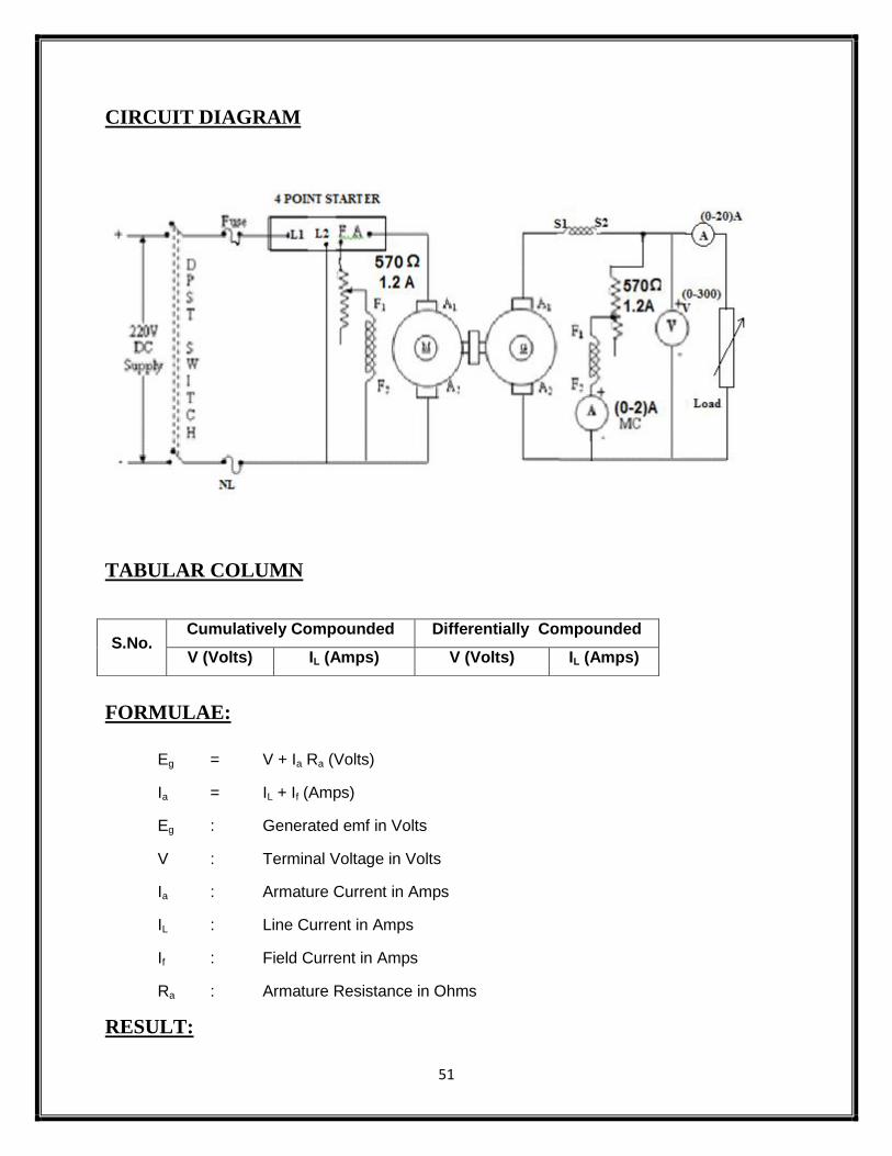
CIRCUIT DIAGRAM
TABULAR COLUMN
FORMULAE:
Eg = V + Ia Ra (Volts)
Ia = IL + If (Amps)
Eg : Generated emf in Volts
V : Terminal Voltage in Volts
Ia : Armature Current in Amps
IL : Line Current in Amps
If : Field Current in Amps
Ra : Armature Resistance in Ohms
RESULT:
S.No. Cumulatively Compounded Differentially Compounded
V (Volts) IL (Amps) V (Volts) IL (Amps)
52
EX. NO. :11
DATE :
SUMPNER’S TEST ON A PAIR OF 1-Ф TRANSFORMER
AIM:
To conduct OC & SC tests on the given 1- Transformer and to calculate its
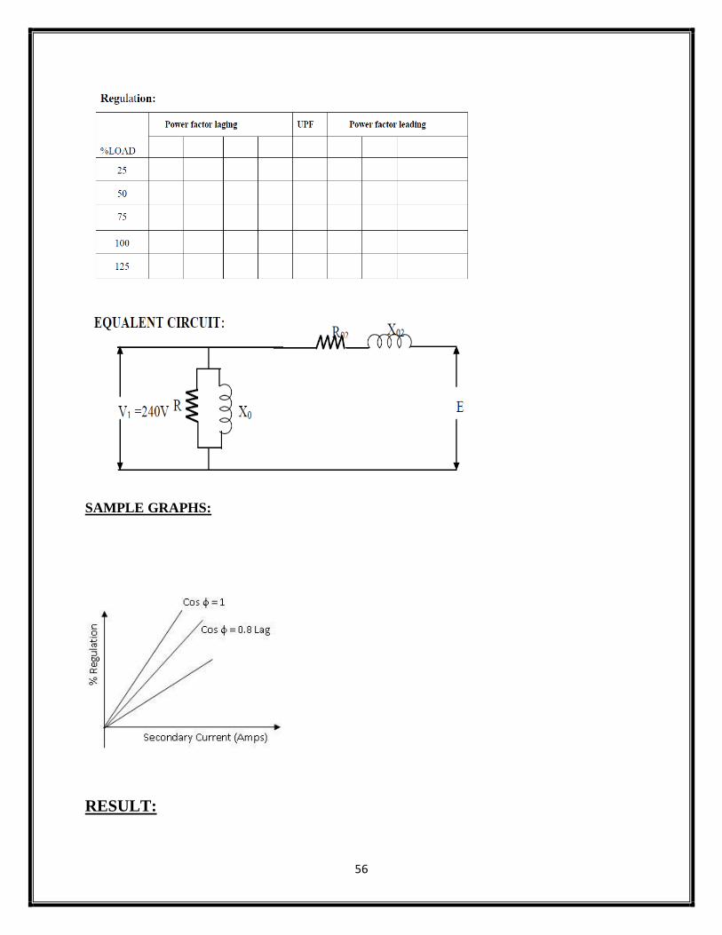
1) Equivalent circuit parameters
a). Referred to H.V side
b). Referred to L.V side
2) Efficiency at various loads.
3) Regulation at various power factors
4) Maximum Efficiency.
APPARATUS REQUIRED:
MACHINES DETAILS:
THEORY :
In this test load test is conducted without actual loading.Sumpner’s test which can
onlybe conducted simultaneously on two identical transformers. In conducting the
Sumner’stestthe primaries of the two transformers are connected in parallel across
the rated voltagesupply (V1), while the two secondary’s are connected in phase
opposition. As per thesuperposition theorem, if V2 source is assumed shorted, the
Sl
no Name of Apparatus Type Specification Qty
1 Ammeter
2 Voltmeter
3 Rheostat
4 Tachometer
53
two transformers appear in open circuit to source V1 as their secondary are in
phase opposition and therefore no currentcan flow in them. The current drawn
from source V1 is thus 2I0 (twice the no-load current of each transformer) and
power is 2P0 (= 2P0, twice the core loss of each transformer). When V1 is regarded
as shorted, the transformers are series-connected across V2 and are short-
circuitedon the side of primaries. Therefore, the impedance seen at V2 is 2Z and
whenV2 is adjusted tocirculate full-load current (Ifl), the power fed in is 2Pc (twice
the full-load copper-loss of eachtransformer). Thus in the Sumpner’s test while the
transformers are not supplying any load,full iron-loss occurs in their core and full
copper-loss occurs in their windings; net powerinput to the transformers
being(2Po+2Pc).The heat run test could , therefore, be conducted onthe two
transformers, while only losses are supplied.
For each trans former the results are Voltage =V1 , Current = I0 /2 , Core losses = P0 /2
Voltage =Vsc/2 , Current = Isc, Copper losses = Psc/2
P0 = Pi (iron-loss)
P0 = V1 I0cos0
cos0 = P0 / V1 I0
Iw= I0cos0, I= I0sin0
R0 = V1/ Iw, X0 = V1 / I.
Vsc=Voltage, Isc= Current ,Psc= Power (Copper loss)
54
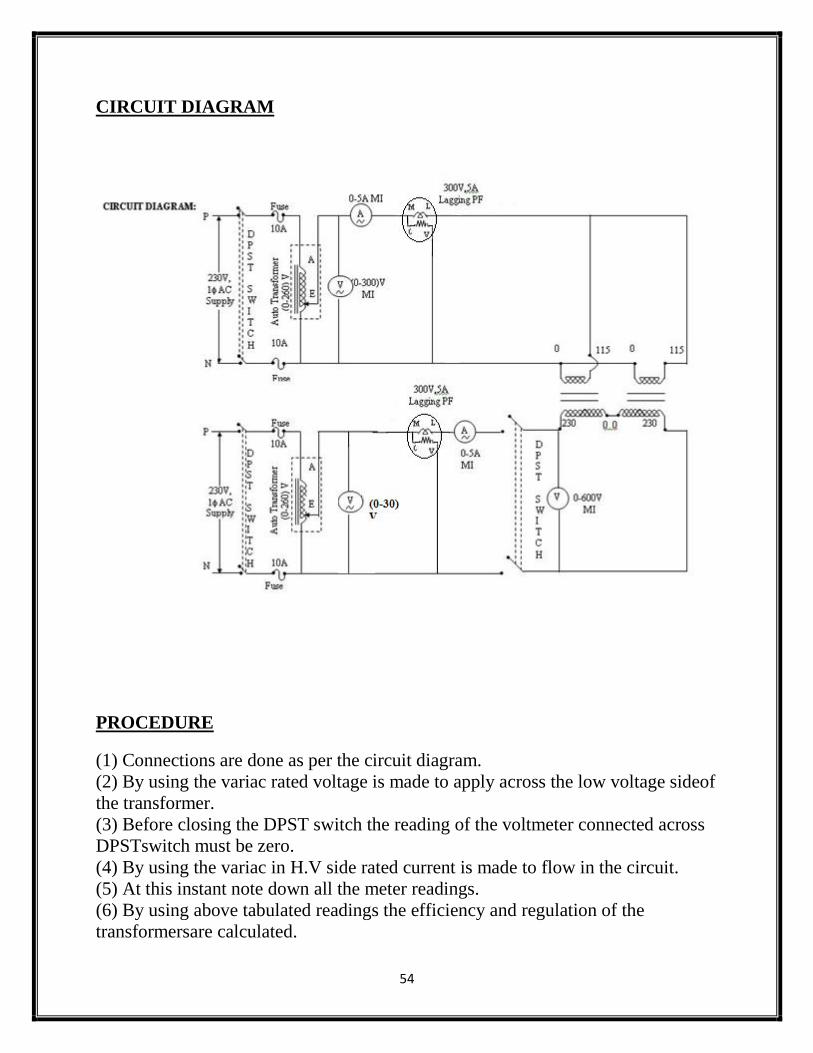
CIRCUIT DIAGRAM
PROCEDURE
(1) Connections are done as per the circuit diagram.
(2) By using the variac rated voltage is made to apply across the low voltage sideof
the transformer.
(3) Before closing the DPST switch the reading of the voltmeter connected across
DPSTswitch must be zero.
(4) By using the variac in H.V side rated current is made to flow in the circuit.
(5) At this instant note down all the meter readings.
(6) By using above tabulated readings the efficiency and regulation of the
transformersare calculated.
55
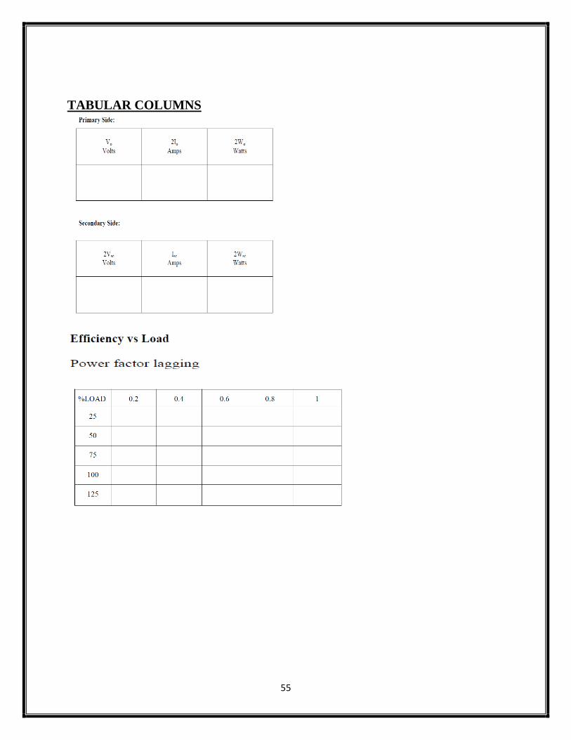
TABULAR COLUMNS
56
SAMPLE GRAPHS:
RESULT:
57
EX. NO. :12
DATE :
SEPARATION OF NO LOAD LOSSES IN A SINGLE PHASE
TRANSFORMER
AIM:
To separate no load losses of a transformer in to eddy current loss and hysteresis
loss.
APPARATUS REQUIRED:
THEORY:
It is seen that the core losses of transformer includes,
1. Hysteresis loss
2. Eddy current loss
For a given volume and thickness of laminations, these losses depend on the
operating frequency, maximum flux density in the core and the voltage.
The hysteresis loss is given by Steinmet'z relation,
Ph = Kh Bm1.67
f v watts
i.e. Ph = A Bm1.67
f watts ..............(1)
where A = constant assuming constant voltage
The eddy current loss is given by,
Pe = Ke Bm2 f
2 t
2 watts
i.e. Pe = B Bm2 f
2 watts .........(2)
where B = constant for given thickness t of core
Thus the total core loss becomes,
Pi = Ph + Pe = A Bm1.67
f +B Bm2 f
2 .........(3)
Sl. No.
Name of the Apparatus
Range Type Quantity
58
Practically conduct two tests on transformers at two different frequencies
f1 and f2, keeping maximum flux density in the core same. The results are to be
used in the equations (1), (2) and (3) to obtain the constants A and B. Thus the core
losses i.e. iron losses can be separated into hysteresis and eddy current losses.
PRECAUTIONS:
1. The motor field rheostat should be kept at minimum resistance position.
2. The alternator field rheostat should be kept at maximum resistance position.
PROCEDURE:
1. Connections are given as per the circuit diagram.
2. Supply is given by closing the DPST switch.
3. The DC motor is started by using the 3 point starter and brought to rated speed
by adjusting itsfield rheostat.
4. By varying the alternator filed rheostat gradually the rated primary voltage is
applied to thetransformer.
5. The frequency is varied by varying the motor field rheostat and the readings of
frequency arenoted and the speed is also measured by using the tachometer.
6. The above procedure is repeated for different frequencies and the readings are
tabulated.
7. The motor is switched off by opening the DPST switch after bringing all the
rheostats to theinitial position.
59
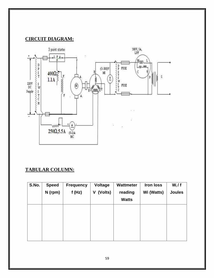
CIRCUIT DIAGRAM:
TABULAR COLUMN:
S.No. Speed
N (rpm)
Frequency
f (Hz)
Voltage
V (Volts)
Wattmeter
reading
Watts
Iron loss
Wi (Watts)
Wi / f
Joules
60
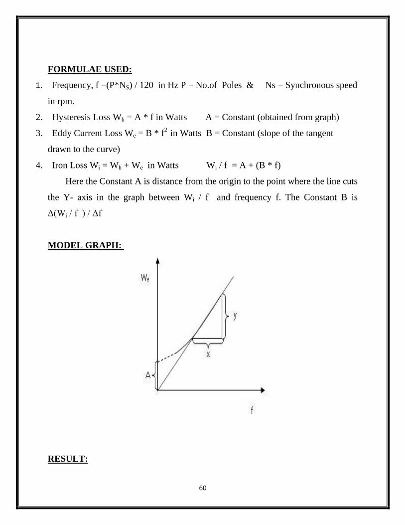
FORMULAE USED:
1. Frequency, f =(P*NS) / 120 in Hz P = No.of Poles & Ns = Synchronous speed
in rpm.
2. Hysteresis Loss Wh = A * f in Watts A = Constant (obtained from graph)
3. Eddy Current Loss We = B * f2
in Watts B = Constant (slope of the tangent
drawn to the curve)
4. Iron Loss Wi = Wh + We in Watts Wi / f = A + (B * f)
Here the Constant A is distance from the origin to the point where the line cuts
the Y- axis in the graph between Wi / f and frequency f. The Constant B is
Δ(Wi / f ) / Δf
MODEL GRAPH:
RESULT:

61


![Electrical Machines Lab II Manual[1]](https://img.pdfslide.net/doc/110x75/553d18505503467a438b4d47/electrical-machines-lab-ii-manual1.jpg)