Embed Size (px)
Citation preview
This article was downloaded by: [UZH Hauptbibliothek / Zentralbibliothek Zürich]On: 05 September 2013, At: 06:36Publisher: Taylor & FrancisInforma Ltd Registered in England and Wales Registered Number: 1072954 Registeredoffice: Mortimer House, 37-41 Mortimer Street, London W1T 3JH, UK
Waves in Random and Complex MediaPublication details, including instructions for authors andsubscription information:http://www.tandfonline.com/loi/twrm20
A highly efficient numerical solutionfor dielectric-coated PEC targetsShiquan He a , Zaiping Nie a , Jiangong Wei a & Jun Hu aa School of Electronic Engineering, University of ElectronicScience and Technology of China (UESTC), Chengdu, 610054, P. R.ChinaPublished online: 16 Feb 2009.
To cite this article: Shiquan He , Zaiping Nie , Jiangong Wei & Jun Hu (2009) A highly efficientnumerical solution for dielectric-coated PEC targets, Waves in Random and Complex Media, 19:1,65-79, DOI: 10.1080/17455030802520883
To link to this article: http://dx.doi.org/10.1080/17455030802520883
PLEASE SCROLL DOWN FOR ARTICLE
Taylor & Francis makes every effort to ensure the accuracy of all the information (the“Content”) contained in the publications on our platform. However, Taylor & Francis,our agents, and our licensors make no representations or warranties whatsoever as tothe accuracy, completeness, or suitability for any purpose of the Content. Any opinionsand views expressed in this publication are the opinions and views of the authors,and are not the views of or endorsed by Taylor & Francis. The accuracy of the Contentshould not be relied upon and should be independently verified with primary sourcesof information. Taylor and Francis shall not be liable for any losses, actions, claims,proceedings, demands, costs, expenses, damages, and other liabilities whatsoeveror howsoever caused arising directly or indirectly in connection with, in relation to orarising out of the use of the Content.
This article may be used for research, teaching, and private study purposes. Anysubstantial or systematic reproduction, redistribution, reselling, loan, sub-licensing,systematic supply, or distribution in any form to anyone is expressly forbidden. Terms &Conditions of access and use can be found at http://www.tandfonline.com/page/terms-and-conditions
Waves in Random and Complex MediaVol. 19, No. 1, February 2009, 65–79
A highly efficient numerical solution for dielectric-coated PEC targets
Shiquan He∗, Zaiping Nie, Jiangong Wei and Jun Hu
School of Electronic Engineering, University of Electronic Science and Technology of China(UESTC), Chengdu, 610054, P. R. China
(Received 29 July 2008; final version received 25 September 2008)
In this paper, the multi-layer TDS (thin dielectric sheet) integral equation approach isfirst proposed. This method divides the geometric model into multiple thin layers andassumes the flux density to be constant with respect to the normal direction within eachlayer. Consequently, the number of unknowns is significantly reduced while the preci-sion of the results could be maintained. Then, the multi-layer TDS integral approachis combined with the PEC (perfect electric conductor) boundary conditions together tohandle scattering from dielectric coated PEC objects. This new procedure simplifies thecoupled surface (for the conductor)–volume (for dielectric) integral to a surface–surfaceintegral with much fewer unknowns. Furthermore, a remedy approach is also presentedin this paper to improve the deteriorated precision for open composed structures dueto the significant singular currents near the boundary edges. Compared with traditionalPEC-TDS methods, the method presented in this paper can deal with scattering fromthick or stratified coatings with arbitrarily lateral or normal inhomogeneity. Its im-provement is also capable of handling dielectric coatings on open PEC surfaces. Thenumerical results at the end show good agreement with the references, showing theaccuracy and the validity of these solutions.
1. Introduction
Under many circumstances, it is essential to research into scattering from dielectric-coatedconductors because, for many conducting-dielectric objects, the dielectric is coated on thewhole surface of the conductor. It is known that the RCS can be reduced by coatings withproper dielectric constant and thickness. Furthermore, some scatterers are usually coatedby dielectric media for protection or aerodynamic reasons. These applications necessitateelectromagnetic solvers that can tackle composite metallic and dielectric materials. Amongthem, the integral equation approaches with the method of moments (MoM) [1] or fastalgorithms [2] are popular for their generality, versatility, and less restriction in geometryand material modelling.
The conducting component of a hybrid object is usually modelled as a perfect electricconductor (PEC) and the surface integral equation (SIE) with RWG basis [3] or curvi-linear RWG [4] basis is widely adopted. For the dielectric component, either the volumeintegral equation (VIE) approach [5–9] or combined-field PMCHWT integral equationsapproach [10,11] is used. The volume integral equation approach, solved by MoM [5–7] orMLFMA [8,9], is one of the popular analysis methods, due to its flexibility and capabilityof handling arbitrary shapes and inhomogeneity. However, it suffers from rapid growth of
∗Corresponding author. Email: [email protected]
ISSN: 1745-5030 print / 1745-5049 onlineC© 2009 Taylor & Francis
DOI: 10.1080/17455030802520883http://www.informaworld.com
Dow
nloa
ded
by [
UZ
H H
aupt
bibl
ioth
ek /
Zen
tral
bibl
ioth
ek Z
üric
h] a
t 06:
36 0
5 Se
ptem
ber
2013
66 S. He et al.
computational complexity with increase of the grid size. The unknowns from a 3D volumemesh are so enormous that the huge requirement for memory storage and CPU time issimply unacceptable. In general, the PMCHWT approach is more efficient than the VIEapproach for homogeneous dielectric problems since the unknowns of the PMCHWT arethe surface electric and magnetic currents, which are defined on the surface of the dielectricbody. However, it tends to suffer from poor convergence problems, especially when the di-electric constant is relatively high. Although much effort [12–14] has attempted to mitigatethis defect, these methods are only suitable for the homogeneous or block-homogeneousdielectric problem. And in a stratified medium situation, each interface must be discretized,leading to a significant increase in the number of unknowns.
In recent years, some efficient solutions have been proposed for the special case that thedielectric component is a thin dielectric sheet with a very small thickness. Among them,the impedance boundary condition (IBC) method [15] and the thin dielectric sheet (TDS)approximation method [16–21] are the most representative.
The impedance boundary condition [15], relating tangential electric and magnetic fieldson the metal surface, has provided good numerical results. However, the impedance mustbe measured experimentally, or approximated assuming that the PEC body is locally flatand an analytical expression for the impedance of an infinite, tangent plane is inserted.
The thin dielectric sheet approximation was first proposed by Harrington in 1975 [16]and some researchers have developed this method in recent years [17–21]. The most im-portant point of the thin dielectric sheet approximation is the assumption that the tangentialcomponent of the volume polarization current in the dielectric is constant in the normaldirection. Then, the traditional volume integral equation is reduced to a surface integralequation with a few surface basis functions to expand the tangential current. The contribu-tion from the normal polarization current was either ignored [16], approximated with theincident fields [17], or described by the additional vector pulse basis functions [18]. Thethin dielectric sheet approximation is quite attractive because the integral equation here isvery similar to the surface integral equation for PEC and it generates fewer unknowns thanVIE and PMCHWT. The strategy can be easily combined with the SIE for PEC to calculatethinly dielectric-coated PEC objects [19]. Recently, Davis and Chew [20] provided a sim-plified model for dielectric-coated metallic surfaces by combining the thin dielectric sheetapproximation with explicit boundary conditions at the interface between the conductor anddielectric, removing the unknowns in the dielectric region. Although the above methods aremost efficient, they all require the dielectric sheet to be thin (typically less than one tenthof a wavelength in the dielectric) and neither of them can handle coating problems withmultiple layers.
As a development of the above methods, we extended and applied the thin dielectric sheetapproximation method to the scattering problem for thick or multilayer dielectric sheets[21]. We stratified the geometry model into multiple layers and assumed the distribution ofthe polarization current in the normal direction is maintained constant in the same sublayer,leading to a surface integral instead of the volume integral, and consequently reducing thenumber of unknowns because only surface meshes are utilized to discretize the geometry.Considering the boundary condition that the normal component of the D flux is continuousacross the interfaces between the adjacent layers, the unknowns for the normal componentscould be further retrenched. As a result, the number of unknowns for an N -layer object isN × 1.5P + P, where P stands for the average number of triangular patches in each layer.
In this paper, we attempt to hybridize the multi-layer TDS integral approach withthe PEC boundary conditions so that dielectric-coated conductors can be handled in astraightforward manner. Approximating the tangential component of the D flux that is near
Dow
nloa
ded
by [
UZ
H H
aupt
bibl
ioth
ek /
Zen
tral
bibl
ioth
ek Z
üric
h] a
t 06:
36 0
5 Se
ptem
ber
2013
Waves in Random and Complex Media 67
the PEC surface to zero and utilizing the explicit boundary conditions as in [6], the currentmodel can be further simplified. By adopting the curvilinear RWG as the basis functions,the coupled PEC-multilayer TDS integral equation set is finally solved with MLFMA. Thisprovides a faster solution than the VSIE approach [6,8], and hopefully it can be an attractivealternative for the initial phase of the design process.
2. Coupled PEC-multilayer TDS integral formulations
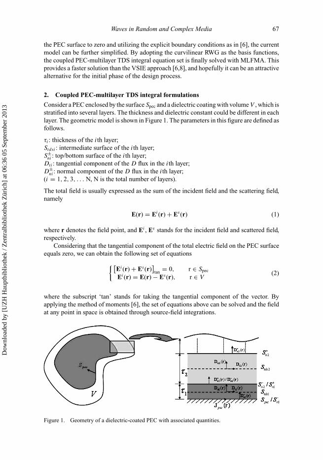
Consider a PEC enclosed by the surface Spec and a dielectric coating with volume V , which isstratified into several layers. The thickness and dielectric constant could be different in eachlayer. The geometric model is shown in Figure 1. The parameters in this figure are defined asfollows.
τi : thickness of the ith layer;Stdsi : intermediate surface of the ith layer;S±
ni : top/bottom surface of the ith layer;Dti : tangential component of the D flux in the ith layer;D±
ni : normal component of the D flux in the ith layer;(i = 1, 2, 3, . . . N, N is the total number of layers).
The total field is usually expressed as the sum of the incident field and the scattering field,namely
E(r) = Ei(r) + Es(r) (1)
where r denotes the field point, and Ei , Es stands for the incident field and scattered field,respectively.
Considering that the tangential component of the total electric field on the PEC surfaceequals zero, we can obtain the following set of equations
{[Ei(r) + Es(r)
]tan
= 0, r ∈ Spec
Ei(r) = E(r) − Es(r), r ∈ V(2)
where the subscript ‘tan’ stands for taking the tangential component of the vector. Byapplying the method of moments [6], the set of equations above can be solved and the fieldat any point in space is obtained through source-field integrations.
Figure 1. Geometry of a dielectric-coated PEC with associated quantities.
Dow
nloa
ded
by [
UZ
H H
aupt
bibl
ioth
ek /
Zen
tral
bibl
ioth
ek Z
üric
h] a
t 06:
36 0
5 Se
ptem
ber
2013
68 S. He et al.
The scattering field includes contributions from both the conductor and the dielectric,that is
Es(r) = Espec(r) + Es
die(r)
= iωµ0
⎡⎢⎣
∫Spec
dr′G(r, r
′) • Jpec(r
′) +
∫V
dr′G(r, r
′) • JV (r
′)
⎤⎥⎦ . (3)
Here, G(r, r′) is the dyadic Green function, Jpec is the conducted surface current den-
sity on Spec, and JV represents the volume polarization current density in V , defined byJv(r) = iω(ε0 − ε)E(r) = iωχ (r)D(r), where χ (r) = 1
εr (r) − 1 is the contrast ratio. Allother quantities are defined according to convention [18].
The scattering fields from the PEC and dielectric components can be further establishedas
Espec(r) = iωµ0
⎡⎢⎣
∫Spec
Jpec(r′)g(r, r′) + 1
k20
∇g(r, r′)∇′ • Jpec(r′)dS
′
⎤⎥⎦ (4)
Esdie(r) = iωµ0
⎡⎣∫
V
Jv(r′)g(r, r′) + 1
k20
∇g(r, r′)∇′ • Jv(r′)dV
′
⎤⎦ (5)
where g(r, r′) is the scalar Green function
∇ • Jv(r) = iω∇ • [χ (r)D(r)] = iω [∇χ (r) • D(r) + χ (r)∇ • D(r)] . (6)
Because the first term of the right-hand side in the equation above is zero except on theinterface SA, where the dielectric constant is different across each side,
∇χ (r) • D(r) = −δ(r)[χ+(r) − χ−(r)
]n • D(r), r ∈ SA (7)
where δ(r) stands for the delta function, χ± is the contrast ratio at each side and the unitvector n points from + to −.
Taking account that ∇ • D(r) = 0, we substitute (6) into (5), and finally we get contri-butions from the dielectric component:
Esdie(r) = iωµ0
⎧⎨⎩
∫V
iωχ (r′)D(r
′)g(r, r
′)dV
′
− iω
k20
∫SA
[χ+(r
′) − χ−(r
′)]∇g(r, r
′)n • D(r
′)dS
′
⎫⎬⎭ . (8)
Dow
nloa
ded
by [
UZ
H H
aupt
bibl
ioth
ek /
Zen
tral
bibl
ioth
ek Z
üric
h] a
t 06:
36 0
5 Se
ptem
ber
2013
Waves in Random and Complex Media 69
To reduce the volume integral in Equation (2) to a surface integral, it is necessary todecompose the D flux into tangential and normal components within the ith layer:
Di(r) = Dt i(r) + Dni(r) ≈ Dt i(r) + D−ni(r) (9)
Then, let us consider a two-layer dielectric coating as a numerical example. The integralsin expression (8) can be approximated:
∫V
χ (r′)D(r
′)g(r, r
′)dV
′
≈∫
Stds1
τ1χ1g(Dt1 + D−n1)dS
′ +∫
Stds2
τ2χ2g(Dt2 + D−n2)dS
′(10)
∫SA
[χ+(r′) − χ−(r
′)]∇g(r, r
′)n
′ • D(r′)dS
′
= −∫S−
n1
χ1∇gn′ • D−
n1dS′ +
∫S+
n1
(χ1 − χ2)∇gn′ • D+
n1dS′
+∫S+
n2
χ2∇gn′ • D+
n2dS′ +
∫St1
(χ+1 − χ−
1 )∇gt′ • Dt1dS
′
+∫St2
(χ+2 − χ−
2 )∇gt′ • Dt2dS
′(11)
where SA stands for all the interfaces where the dielectric εr (r) is discontinuous at eachside and n
′is the unit normal vector pointing out of the dielectric; χi represents the contrast
ratio in the ith dielectric layer and Sti contributes for the lateral inhomogeneity.The last two terms in formula (11) can be further approximated to a line integral:
∫Sti
(χ+i − χ−
i )∇gt′ • Dt idS
′ ≈∫Ci
τi(χ+i − χ−
i )∇gt′ • Dt idl
′(12)
Now, the volume integral in (5) degenerates into a surface integral. In the following, wewill further simplify the set of coupled surface–surface integral equations.
The first-order finite difference is utilized to approximate the differential operation asfollows:
∇ • D(r) = 0 = ∇t • Dt i(r) + n • ∂
∂nDni(r)
≈ ∇t • Dt i(r) + n • D+ni(r ∈ S+
ni) − D−ni(r ∈ S−
ni)
τi
. (13)
Because of the normal continuity condition of the D flux,
D−n2 = D+
n1. (14)
Dow
nloa
ded
by [
UZ
H H
aupt
bibl
ioth
ek /
Zen
tral
bibl
ioth
ek Z
üric
h] a
t 06:
36 0
5 Se
ptem
ber
2013
70 S. He et al.
Thus, the following recursions can be readily obtained:
n • D+n1 = n • D−
n1 − τ1∇′t • Dt1(r
′) (15)
n • D+n2 = n • D−
n2 − τ2∇′t • Dt2(r
′)
= n • D−n1 − τ1∇′
t • Dt1(r′) − τ2∇′
t • Dt2(r′). (16)
For a coated PEC system, another two formulas are introduced due to the boundaryconditions at the interface between the conductor and dielectric [20], that is,
n • D−n1 = ∇ • Jpec
/iω (17)
and
Dt1(r′) ≈ 0 (18)
Taking Equations (15)–(18) into account, we find that only Jpec(r),Dt2(r) and Dt3(r), . . .would give rise to unknowns in this system when numerical solutions are utilized to solvethe set of Equations (2). The number of unknowns is much fewer, not only because thequantities, which need to be expanded by basis functions, are retrenched, but also asthese basis functions are just defined on the surface grids (only the conductor surface andintermediate surfaces of each dielectric layer need to be discretized). It is relatively simpleto extend the above derivations to other cases of multi-layered dielectric coatings. If thedielectric coating is single-layered but thicker than one tenth of a wavelength, the scatteringproblem can be solved by dividing the dielectric coating into multiple thin layers. If thedielectric coating is single layered and the thickness is quite limited, the derivations reduceto those in [20].
To solve the final set of coupled surface–surface integral equations, curvilinear RWG(CRWG) basis functions are used to discretize the tangential flux density within each layer(except for the first one) and the induced current on PEC surface. In terms of Galerkin’stesting and MLFMA method, the set of Equations (2) is consequently converted to matrixequations and solved efficiently. The detail is no longer related here because it is similar tothat in [22].
3. Dielectric coating on open PEC surfaces
In practice, we often have to solve the EM scattering from thin conducting sheets ordielectric coatings on them. Thin conducting targets are usually modelled as a piece of PECsurface and the singular current manifests itself strongly on the edges, ridges and cornerson the PEC surface.
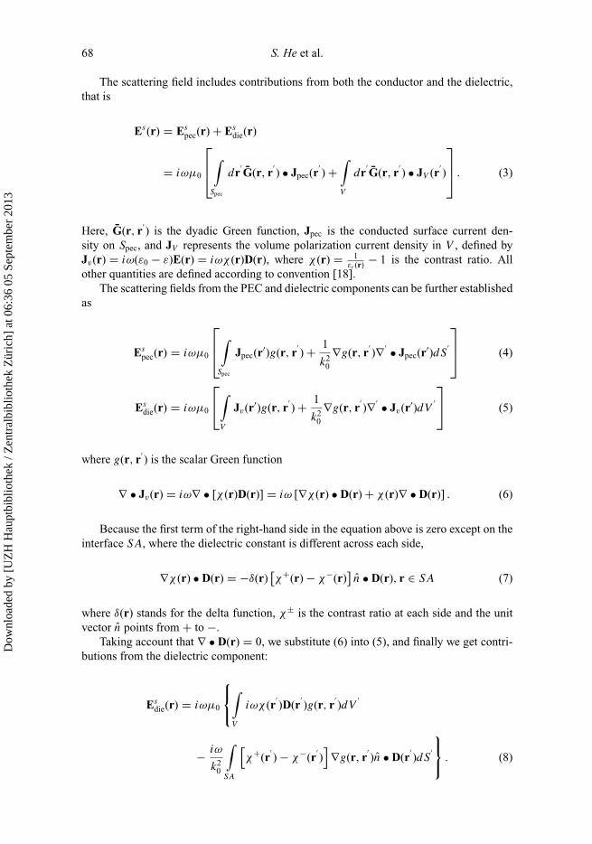
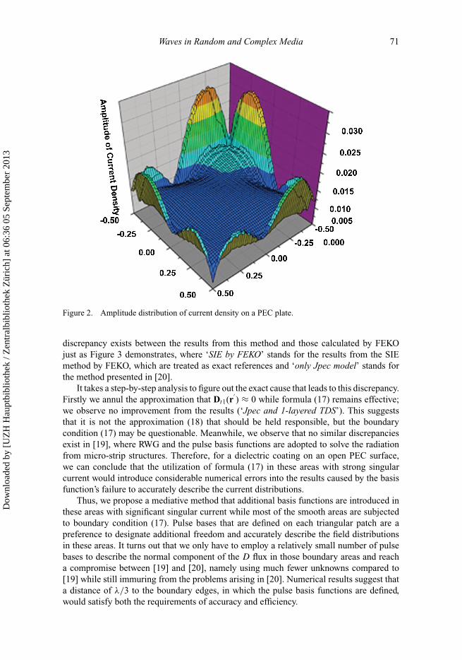
We consider the problem of a coated PEC plate, where the PEC plate is treated as anopen PEC surface. The square plate is of size 1 m × 1 m, located at z = 0 and illuminatedby an incident plane wave from (30◦, 45◦) at 0.3 GHz. The dielectric constant is 2.6 and thethickness is 0.05 m. Figure 2 illustrates the amplitude variations of the current density onthe plate’s surface. Here the dielectric coating is single-layered and the thickness is quitesmall, so the method presented in Section 2 reduces to that in [20]. However, an evident
Dow
nloa
ded
by [
UZ
H H
aupt
bibl
ioth
ek /
Zen
tral
bibl
ioth
ek Z
üric
h] a
t 06:
36 0
5 Se
ptem
ber
2013
Waves in Random and Complex Media 71
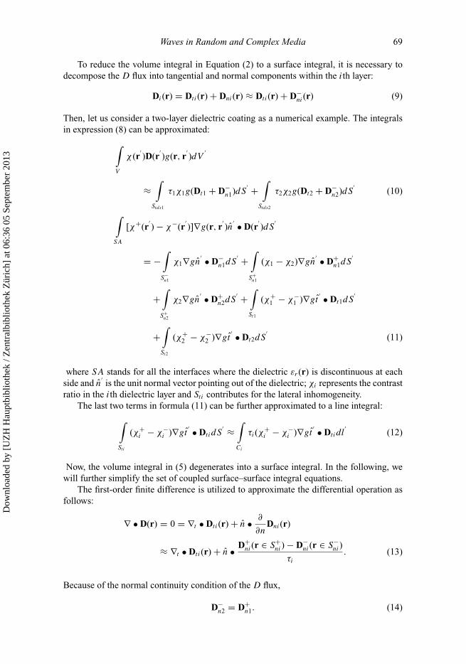
Figure 2. Amplitude distribution of current density on a PEC plate.
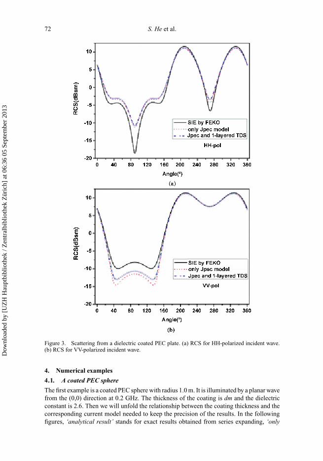
discrepancy exists between the results from this method and those calculated by FEKOjust as Figure 3 demonstrates, where ‘SIE by FEKO’ stands for the results from the SIEmethod by FEKO, which are treated as exact references and ‘only Jpec model’ stands forthe method presented in [20].
It takes a step-by-step analysis to figure out the exact cause that leads to this discrepancy.Firstly we annul the approximation that Dt1(r
′) ≈ 0 while formula (17) remains effective;
we observe no improvement from the results (‘Jpec and 1-layered TDS’). This suggeststhat it is not the approximation (18) that should be held responsible, but the boundarycondition (17) may be questionable. Meanwhile, we observe that no similar discrepanciesexist in [19], where RWG and the pulse basis functions are adopted to solve the radiationfrom micro-strip structures. Therefore, for a dielectric coating on an open PEC surface,we can conclude that the utilization of formula (17) in these areas with strong singularcurrent would introduce considerable numerical errors into the results caused by the basisfunction’s failure to accurately describe the current distributions.
Thus, we propose a mediative method that additional basis functions are introduced inthese areas with significant singular current while most of the smooth areas are subjectedto boundary condition (17). Pulse bases that are defined on each triangular patch are apreference to designate additional freedom and accurately describe the field distributionsin these areas. It turns out that we only have to employ a relatively small number of pulsebases to describe the normal component of the D flux in those boundary areas and reacha compromise between [19] and [20], namely using much fewer unknowns compared to[19] while still immuring from the problems arising in [20]. Numerical results suggest thata distance of λ/3 to the boundary edges, in which the pulse basis functions are defined,would satisfy both the requirements of accuracy and efficiency.
Dow
nloa
ded
by [
UZ
H H
aupt
bibl
ioth
ek /
Zen
tral
bibl
ioth
ek Z
üric
h] a
t 06:
36 0
5 Se
ptem
ber
2013
72 S. He et al.
Figure 3. Scattering from a dielectric coated PEC plate. (a) RCS for HH-polarized incident wave.(b) RCS for VV-polarized incident wave.
4. Numerical examples
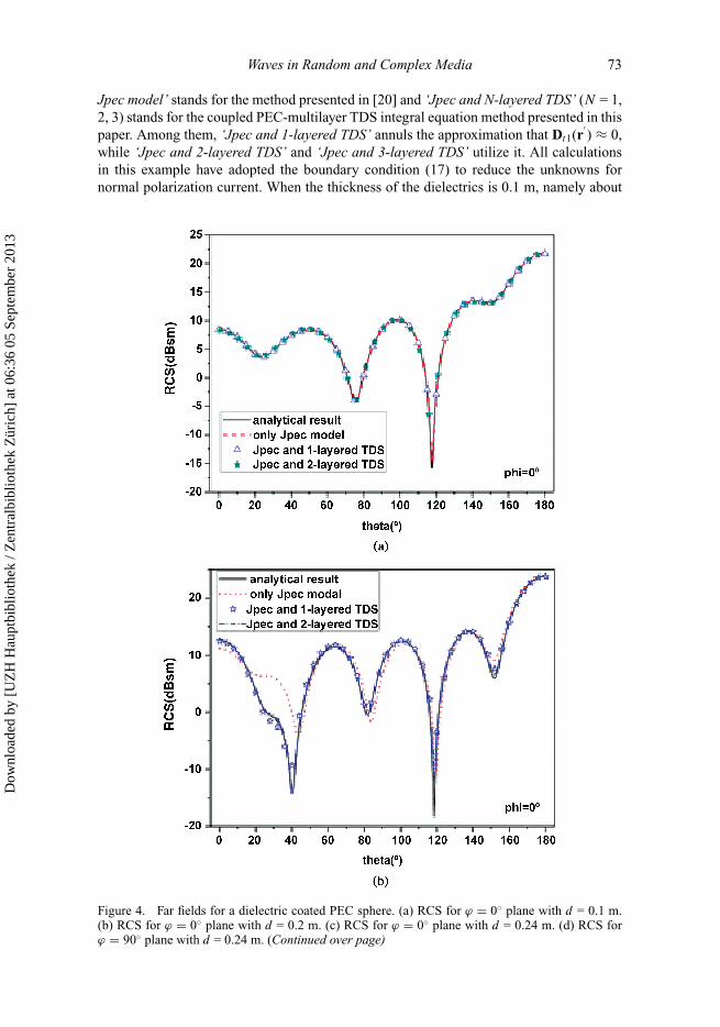
4.1. A coated PEC sphere
The first example is a coated PEC sphere with radius 1.0 m. It is illuminated by a planar wavefrom the (0,0) direction at 0.2 GHz. The thickness of the coating is dm and the dielectricconstant is 2.6. Then we will unfold the relationship between the coating thickness and thecorresponding current model needed to keep the precision of the results. In the followingfigures, ‘analytical result’ stands for exact results obtained from series expanding, ‘only
Dow
nloa
ded
by [
UZ
H H
aupt
bibl
ioth
ek /
Zen
tral
bibl
ioth
ek Z
üric
h] a
t 06:
36 0
5 Se
ptem
ber
2013
Waves in Random and Complex Media 73
Jpec model’ stands for the method presented in [20] and ‘Jpec and N-layered TDS’ (N = 1,2, 3) stands for the coupled PEC-multilayer TDS integral equation method presented in thispaper. Among them, ‘Jpec and 1-layered TDS’ annuls the approximation that Dt1(r
′) ≈ 0,
while ‘Jpec and 2-layered TDS’ and ‘Jpec and 3-layered TDS’ utilize it. All calculationsin this example have adopted the boundary condition (17) to reduce the unknowns fornormal polarization current. When the thickness of the dielectrics is 0.1 m, namely about
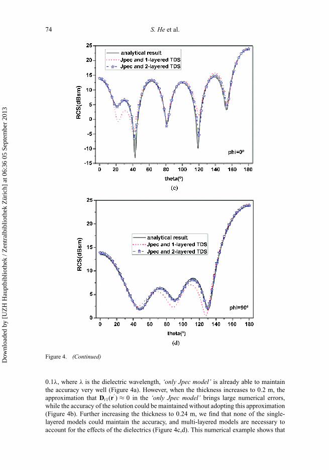
Figure 4. Far fields for a dielectric coated PEC sphere. (a) RCS for ϕ = 0◦ plane with d = 0.1 m.(b) RCS for ϕ = 0◦ plane with d = 0.2 m. (c) RCS for ϕ = 0◦ plane with d = 0.24 m. (d) RCS forϕ = 90◦ plane with d = 0.24 m. (Continued over page)
Dow
nloa
ded
by [
UZ
H H
aupt
bibl
ioth
ek /
Zen
tral
bibl
ioth
ek Z
üric
h] a
t 06:
36 0
5 Se
ptem
ber
2013
74 S. He et al.
Figure 4. (Continued)
0.1λ, where λ is the dielectric wavelength, ‘only Jpec model’ is already able to maintainthe accuracy very well (Figure 4a). However, when the thickness increases to 0.2 m, theapproximation that Dt1(r
′) ≈ 0 in the ‘only Jpec model’ brings large numerical errors,
while the accuracy of the solution could be maintained without adopting this approximation(Figure 4b). Further increasing the thickness to 0.24 m, we find that none of the single-layered models could maintain the accuracy, and multi-layered models are necessary toaccount for the effects of the dielectrics (Figure 4c,d). This numerical example shows that
Dow
nloa
ded
by [
UZ
H H
aupt
bibl
ioth
ek /
Zen
tral
bibl
ioth
ek Z
üric
h] a
t 06:
36 0
5 Se
ptem
ber
2013
Waves in Random and Complex Media 75
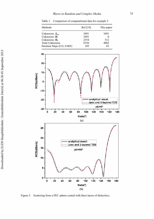
Table 1. Comparison of computational data for example 3
Methods Ref [19] This paper
Unknowns: Jpec 3491 3491Unknowns: Dt 3491 0Unknowns: Dn 2354 512Total Unknowns 9336 4003Iteration Steps (CG, 0.005) 105 83
Figure 5. Scattering from a PEC sphere coated with three layers of dielectrics.
Dow
nloa
ded
by [
UZ
H H
aupt
bibl
ioth
ek /
Zen
tral
bibl
ioth
ek Z
üric
h] a
t 06:
36 0
5 Se
ptem
ber
2013
76 S. He et al.
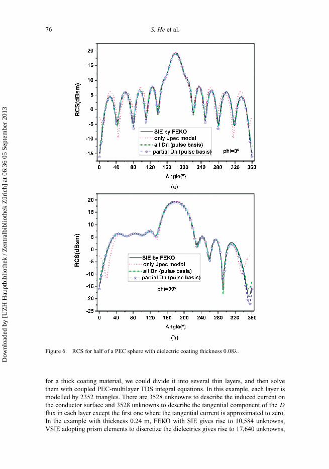
Figure 6. RCS for half of a PEC sphere with dielectric coating thickness 0.08λ.
for a thick coating material, we could divide it into several thin layers, and then solvethem with coupled PEC-multilayer TDS integral equations. In this example, each layer ismodelled by 2352 triangles. There are 3528 unknowns to describe the induced current onthe conductor surface and 3528 unknowns to describe the tangential component of the D
flux in each layer except the first one where the tangential current is approximated to zero.In the example with thickness 0.24 m, FEKO with SIE gives rise to 10,584 unknowns,VSIE adopting prism elements to discretize the dielectrics gives rise to 17,640 unknowns,
Dow
nloa
ded
by [
UZ
H H
aupt
bibl
ioth
ek /
Zen
tral
bibl
ioth
ek Z
üric
h] a
t 06:
36 0
5 Se
ptem
ber
2013
Waves in Random and Complex Media 77
while the proposed method only gives rise to 7056 unknowns, achieving a 33% and 60%saving of unknowns, respectively.
4.2. A PEC sphere coated with three layers of dielectrics
In this example, we calculate a PEC sphere coated with three layers of different dielectricsto demonstrate that the presented method is also valid for stratified coatings. The numericalresults are compared with analytical ones. The radius of the PEC sphere is 1.0 m, thethickness of each layer is assigned as 0.05 m, 0.06 m and 0.04 m, and the dielectric constantis 2.6, 1.8 and 4, respectively. Figure 5 shows the far fields excited by an incident planewave with frequency 0.3 GHz, which agree well with the references. In this example, ourmethod gives rise to 22,938 unknowns while SIE and VSIE would give rise to 52,536 and75,620 unknowns, respectively. Compared with these two methods, we only need 44% and30% of their unknowns.
4.3. Half of a PEC sphere coated with thin dielectric
Finally, we consider an example of a dielectric coating on an open PEC surface. Half ofa PEC sphere with radius 1.0 m is coated by a dielectric with dielectric constant 2.6 andthe thickness is 0.05 m. The incident wave is from (0,0) with frequency 0.3 GHz and thepolarization direction is parallel to the bottom of the half-sphere. Figure 6(a) and (b) showsthe RCS for scanning in the ϕ = 0◦ and ϕ = 90◦ plane, respectively. Consistent with theanalysis in Section 3, ‘only Jpec model’ introduces large numerical errors while the remedymethod is immune from this discrepancy. In the ‘all Dn (pulse basis)’ method, all the normalcomponents of the D flux are expressed with pulse basis functions, which is similar to theprocedure in [19], while Dt1(r
′) is approximated to zero. In the ‘partial Dn (pulse basis)’
method, pulse functions are only defined in these areas with significant singular currentwhile most of the smooth areas are subjected to boundary condition (17). Both methodscould maintain the accuracy while the latter gives rise to fewer unknowns.
A comparison of the unknowns for the last example is demonstrated in Table 1. Main-taining the accuracy as the method proposed in [19], the remedy method proposed inthis paper needs fewer unknowns and the convergence rate is also improved due to theexplicit inclusion of the boundary conditions. The applications of the remedy method tostratified coatings on an open PEC surface are no longer given in this paper due to thelength limitations.
5. Discussions and conclusion
The coupled PEC-multilayer TDS integral method demonstrates the following merits aswell as the multilayer TDS integral equation approach [21]: much fewer unknowns; fastimpedance matrix calculation; availability for arbitrary inhomogeneous material and goodconvergence prosperities. However, this method also suffers from the problems resultingfrom the integral approximations: the assumption that the volume current stays constant inthe normal direction within each thin layer and utilization of the first-order finite differencein the normal flux across a layer. Both of these two approximations limit the thickness ofeach layer (it is usually limited to λ/12 − λ/8, where λ is the dielectric wavelength in thislayer).
According to theoretical analysis and numerical verification, we find that the dominatingerror comes from the recursions (15) and (16). These recursions retrench the final unknowns
Dow
nloa
ded
by [
UZ
H H
aupt
bibl
ioth
ek /
Zen
tral
bibl
ioth
ek Z
üric
h] a
t 06:
36 0
5 Se
ptem
ber
2013
78 S. He et al.
at a cost of fewer degrees of freedom, which take most of the responsibility for the loss ofprecision and the limitation of the thickness within each layer. This can explain why Figure5 shows a fairly large difference between the calculated results and the analytical ones,especially at the lower values of θ . Further work is underway, such as modelling the normalflux density with pulse or roof-top basis functions everywhere. However, the number ofunknowns raised in this way is the same as that from the VIE method using prism elementsto discretize the geometry model [9], achieving no retrenchment in computer memory.
Finally, let us draw some conclusions. In this paper, the recently proposed multi-layerTDS integral equation approach is combined with the boundary condition on a PEC surfaceto handle electromagnetic scattering from dielectric coated PEC objects. For coated targets,the current model can be further simplified and the consumption of computer resourceis dramatically retrenched by approximating the tangential component of the D flux inthe dielectrics apprised to the PEC to be zero, and utilizing the boundary conditions atthe interface between the conductor and dielectric to spare the directly computation of thenormal current. Then, the coupled PEC-multilayer TDS integral equations are solved by themulti-level fast multipole algorithm (MLFMA) with CRWG bases as the basis functions.However, in the case of open PEC surfaces, the simplified model generates large errorsdue to the significant singular currents near the boundary edges. To overcome this defect,a remedy method that introduces additional pulse basis functions only in these boundaryareas is presented. In this paper, first we propose a highly efficient numerical method tohandle the scattering problems from thick or layered coatings with arbitrary inhomogeneity,and then we present a remedy approach for a dielectric coating on open PEC surfaces. Thenumerical results from our approaches show good agreement with others while they needmuch fewer unknowns.
References[1] R.F. Harrington, Field Computation by Moment Methods, MacMillan, New York, 1968.[2] W.C. Chew, J.M. Jin, E. Michielssen, and J.M. Song, Fast and Efficient Algorithms in Compu-
tational Electromagnetics, Artech House, Boston, 2001.[3] S.M. Rao, D.R. Wilton, and A.W. Glisson, Electromagnetic scattering by surfaces of arbitrary
shape, IEEE Trans. Antennas Propag. AP-30 (1982), pp. 409–418.[4] K.C. Donepudi, K. Gang, J.M. Song, W.C. and Chew, Higher-order MoM implementation to
solve integral equations, in IEEE Antennas and Propagation Society International Symposium,vol. 3, 11–16, July 1999, pp. 1716–1719.
[5] D.H. Schaubert, D.R.Wilton, and A.W. Glisson, A tetrahedral modeling method for electromag-netic scattering by arbitrarily shaped inhomogeneous dielectric bodies, IEEE Trans. AntennasPropag. AP-32 (1984), pp. 77–85.
[6] C.C. Lu and W.C. Chew, A couples surface-volume integral equation approach for the calcu-lation of electromagnetic scattering from composite metallic and material targets, IEEE Trans.Antennas Propag. 48 (2000), pp. 1866–1868.
[7] J.P. Creticos and D.H. Schaubert, Electromagnetic scattering by mixed conductor-dielectricbodies of arbitrary shape, IEEE Trans. Antennas Propag. 54 (2006), pp. 2402–2407.
[8] C.C. Lu, A fast algorithm based on volume integral equation for analysis of arbitrarily shapeddielectric radomes, IEEE Trans. Antennas Propag. 51 (2003), pp. 606–612.
[9] Z. Zeng and C.-C. Lu, Discretization of hybrid VSIE using mixed mesh elements with zeroth-order Galerkin basis functions, IEEE Trans. Antennas Propag. 54 (2006), pp. 1863–1870.
[10] A.J. Poggio and E.K. Miller, Integral equation solutions of three-dimensional scattering prob-lems, in Computer Techniques for Electromagnetics, R. Mittra, ed., Pergamon Press, Oxford,1973, Chap. 4.
[11] R.F. Harrington, Boundary integral formulations for homogeneous material bodies, J. Electro-magn. Waves Applicat. 3 (1989), pp. 1–15.
Dow
nloa
ded
by [
UZ
H H
aupt
bibl
ioth
ek /
Zen
tral
bibl
ioth
ek Z
üric
h] a
t 06:
36 0
5 Se
ptem
ber
2013
Waves in Random and Complex Media 79
[12] X.Q. Sheng, J.M. Jin, J.M. Song, W.C. Chew, and C.C. Lu, Solution of combined-field integralequation using multilevel fast multipole algorithm for scattering by homogeneous bodies, IEEETrans. Antennas Propagat. 46 (1998), pp. 1718–1726.
[13] P. Yla-Oijala, Application of a novel CFIE for electromagnetic scattering by dielectric objects,Microwave Opt. Technol. Lett. 35 (2002), pp. 3–5.
[14] P. Yla-Oijala and T Matti, Application of combined field integral equation for electromagneticscattering by dielectric and composite objects, IEEE Trans. Antennas Propagat. 53 (2003), pp.1168–1173.
[15] E. Bleszynski, M. Bleszynski, and T. Jaroszewicz, Surface-integral equations for electromag-netic scattering from impenetrable and penetrable sheets, IEEE Antennas Propagat. Mag. 35(1993), pp. 14–25.
[16] R.F. Harrington and J.R. Mautz, An impedance sheet approximation for thin dielectric shells,IEEE Trans. Antennas Propagat. 23 (1975), pp. 531–534.
[17] C. Lu, A modified thin dielectric approximation for calculation of EM scattering by dielectricobjects with thin material coating, in IEEE Antennas and Propagation International Symposium,9–15 June 2007, pp. 2809–2812.
[18] I.T. Chiang and W.C. Chew, Thin dielectric sheet simulation by surface integral equation usingmodified RWG and pulse bases, IEEE Trans. Antennas Propag. 54 (2006), pp. 1927–1934.
[19] I.T. Chiang and W.C. Chew, A coupled PEC-TDS surface integral equation approach forelectromagnetic scattering and radiation from composite metallic and thin dielectric objects,IEEE Trans. Ant. Prop. 54 (2006), pp. 3511–3516.
[20] C.P. Davis and W.C. Chew, An alternative to impedance boundary conditions for dielectric-coated PEC surfaces, in IEEE Antennas and Propagation Society International Symposium,9–15 June 2007, pp. 2785–2788.
[21] S. He, Z. Nie, S. Yan, and J. Hu, A multi-layer TDS integral equation approach for EM scatteringfrom dielectric objects, revised for IEEE Trans. Antennas Propag.
[22] J. Hu, Z. Nie, and L. Lin, Solving 3-D electromagnetic scattering from conducting object byMLFMA with curvilinear RWG basis, in Antennas, Propagation and EM Theory, Proceedingsof the 6th International Symposium, 28 Oct.–1 Nov. 2003, pp. 460–463.
Dow
nloa
ded
by [
UZ
H H
aupt
bibl
ioth
ek /
Zen
tral
bibl
ioth
ek Z
üric
h] a
t 06:
36 0
5 Se
ptem
ber
2013


![AUTOREFERAT€¦ · [4] R. Lech, W. Marynowski, A. Kusiek, "An Analysis of Elliptical-Rectangular Multipatch Structure on Dielectric-Coated Confocal and Nonconfocal Elliptic Cylinders",](https://img.pdfslide.net/doc/110x75/606655be8257ee71175410ad/autoreferat-4-r-lech-w-marynowski-a-kusiek-an-analysis-of-elliptical-rectangular.jpg)