Embed Size (px)
Citation preview
63IEEE TR.ANSACTIONS ON INSTRUMENTATION ANsD MEASUREMENT, VOIL. INO1-S. NO). 1, MARCHI 1969
A Method for Compensation of Thermal Drift ofFerromagnetic Current Comparator
SUEO TANAKA AND KEITARO SEKINE, MEMBER, IEEE
Abstract-The current comparator using a ferromagnetic corehas several merits especially for application to current A-D con-verters. Because the comparator utilizes the coercive force of thecore to give the threshold value to the performance, drift errorscannot be neglected if the ambient temperature changes. An elec-tronic compensation method for drift and experimental resultsare described.The temperature drift in the performance of the comparator is
decreased from 120 mA to 1 mA over the temperature range of10°C to 55°C. The thermal drift of the compensated comparatoris less than that of the comparator at constant temperature. Usingthe compensation method, accuracy of the current A-D converterwith the comparator is maintained to an order of 0.1 percent ofthe maximum value of the input over wide temperature range.
INTRODLTCTION
HE CURRENT comparator using a ferromag-netic core has several nlerits and is very usefulfor application to current A-D converters [1].
The merits of the A-D converter are its very low inputimpedance, its high impedance between the balancedinput ternminal pair and ground, and its ease of conver-sion of the sum or difference of two currents.The coerciv-e force in rectangular B-H hysteresis char-
acteristics of the core is utilized to give a threshold valueto the performance of the comparator. An output pulse,Nhich shows the result of comiiparison, is induced onlywhen the intensity of the magnetic field in the corecaused by the input currents is higher than the coerciveforce of the core H,. The coercive force varies with tem-perature and this variation brings drift errors to the per-formance of the comparator. Therefore, compensation ofthe drift imust be consideredl to maintain an accuracy ofthe conmparator over a wide temperature range.
This paper describes experimental results of thermaldrift of the ferromagnetic current comparator and aneffective method of compensation.
THERMAL DRIFT OF FERROMAGNETIC CURRENTCOMPARATOR
A basic current comparator using a ferromagnetic corehas three windings as shown in Fig. 1: the input windingIT,V the driving winding Id, and the output winding ep.The comparator induces an output pulse on the epwinding, if an input current I,, is larger than the thresh-old current 1. Fig. 2 shows It versus ep., (the maximumvalue of the output pulse) characteristics at several am-
Manuscript received July 17, 1968.The authors are with the Department of Electrical Communi-
cation, Waseda University, Tokyo, Japan.
Fig. 1. Basic configuration of the current comparator.
1 4
Core. R-45612 Mode.
Windings
E1. -
e lturn5sa Id lturns
06-
0 0-1 0.2 03 04 05 0.6 0.7 08 09 109Input Current lx (A)
Fig. 2. Characteristics of hasic comparator at several ambienttemperatures.
bient teml)leratures. The value of input current at whlichthe curve rises is the threshold I50In this examnple, hvaries with the temperature. It agrees with the tempera-ture variation of the coercive force of the core used.
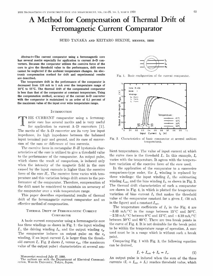
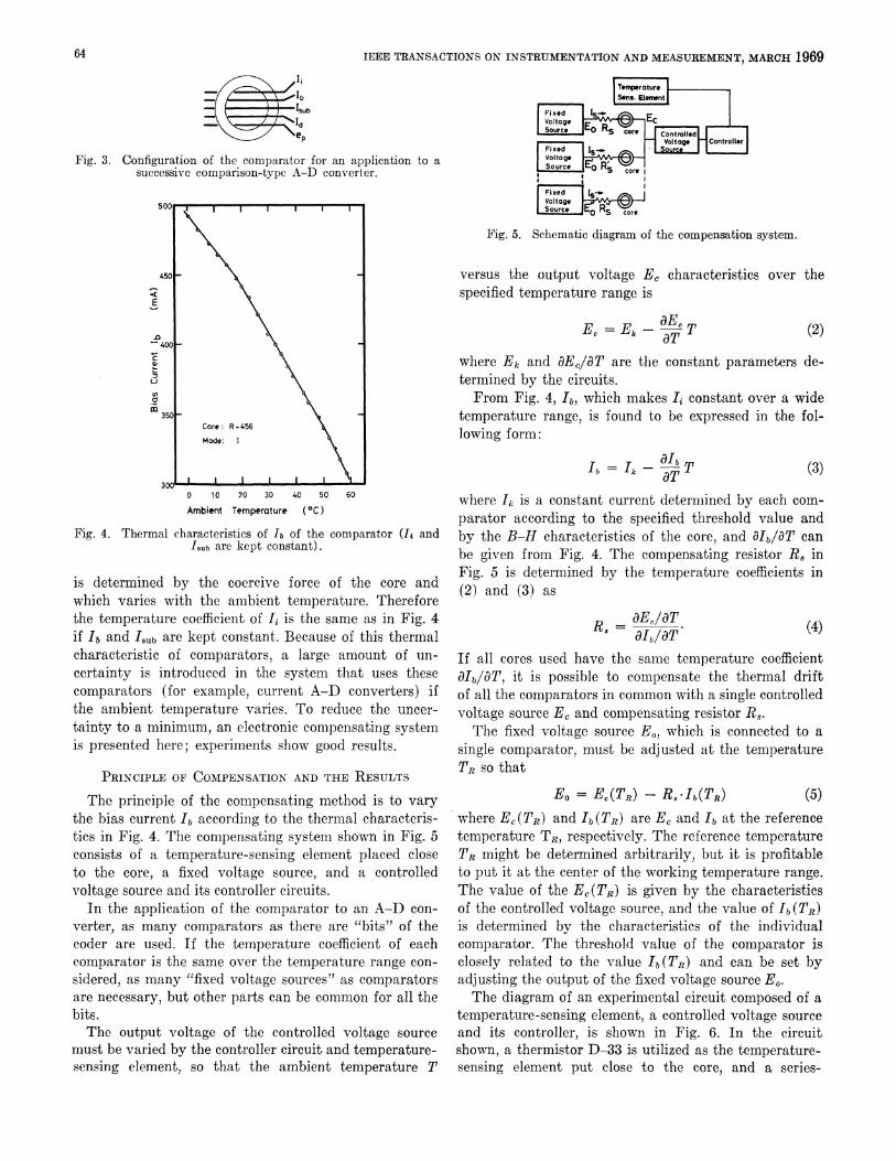
In the application of the comparator to a successivecomparison-type coder, the IZ, winding is replacedl bythlree windlings: the input winding I, the subtractingwrinding 'sub, and the bias winding 'b, as shown in Fig. 3.The thermal drift characteristics of such a comparatorare shown in Fig. 4, in which is plotted the temperaturevariation of bias current 'b that makes the thresholdvalue of the comparator constant for a given t (50 mAin the figune) and a constant fIubcrThe temperature coefficients of 'b in the :Fig. 4 are
-3.43 mA/°C in the range between 15 C and 50°C,-2.53 mA/°C between 0°C and 15IC, and -4.10 mA/°Cbetween 50iC and60FC. There are two break points inthe curve of Fig. 4. It is not desirable for the break pointto be within the temperature range of operation. A coreused must be in a range which is without suchI a breakpoint.Comparing Fig. 1 with Fig. 3, the following equation
can be derived,
Ii + 'sub + lb = I r (1)An output pulse is induced when the sum of the threecurrents (I, + 'S+il± Ib) reaches threshold value, which
IEEE TRANSACTIONS ON INSTRUMENTATION AND MEASUREMENT, MARCH 1969
Fig. 3. Configuration of the comparator for an application to asuccessive comparison-type A-D converter.
Fig. 4. Thermal
0 1 0 20 30 40 50 60
Ambient Temperature (OC)
characteristics of Ib of the comparator (It andIsub are kept constant).
is determined by the coercive force of the core andwhich varies with the ambient temperature. Thereforethe temperature coefficient of It is the same as in Fig. 4if Ib and Isub are kept constant. Because of this thermalcharacteristic of comparators, a large amount of un-certainty is introduced in the system that uses thesecomparators (for example, current A-D converters) ifthe ambient temperature varies. To reduce the uncer-tainty to a minimum, an electronic compensating systemis presented here; experiments show good results.
PRINCIPLE OF COMPENSATION AND THE RESULTS
T'he principle of the compensating method is to varythe bias current Ib according to the thermal characteris-tics in Fig. 4. The compensating system shown in Fig. 5consists of a temperature-sensing element placed closeto the core, a fixed voltage source, and a controlledvoltage source and its controller circuits.
In the application of the comparator to an A-D con-verter, as many comparators as there are "bits" of thecoder are used. If the tempera.ture coefficient of eachcomparator is the same over the temperature range con-sidered, as many "fixed voltage sources" as comparatorsare necessary, but other parts can be common for all thebits.The output voltage of the controlled voltage source
must be varied by the controller circuit and temperature-sensing element, so that the ambient temperature T
lSons. Eleme*nt
Vol tago#Source O Rs core
aVoltage_ Controller
eSource
Fig. 5. Schematic diagram of the compensation system.
versus the output voltage EC characteristics over thespecified temperature range is
EC =Ek - dCTaT (2)
where Ek and aE,/aT are the constant parameters de-termined by the circuits.From Fig. 4, lb, which makes I1 constant over a wide
temperature range, is found to be expressed in the fol-lowing form:
lb = Ik- aIbTdT (3)
where 4 is a constant current determined by each com-parator according to the specified threshold value andby the B-H characteristics of the core, and aIb/9T canbe given from Fig. 4. The compensating resistor Rs inFig. 5 is determined by the temperature coefficients in(2) and (3) as
aEc/aTR= e's aIblaT (4)
If all cores used have the saimie temperature coefficient0Ibl/aT, it is possible to compensate the thermal driftof all the comparators in common with a single controlledvoltage source EC and compensating resistor Rs.The fixed voltage source Eo, which is connected to a
single comparator, must be adjusted at the temperatureTR so that
EO = EC(TR) - RS*Ib(TR) (5)where EC(TR) and Ib(TR) are EC and lb at the referencetemperature TR, respectively. The reference temperatureTR might be determined arbitrarily, but it is profitableto put it at the center of the working temperature range.The value of the EC(T.R) is given by the characteristicsof the controlled voltage source, and the value of Ib(TJR)is determined by the characteristics of the individualcomparator. The threshold value of the comparator isclosely related to the value Ib(TR) and can be set byadjusting the output of the fixed voltage source Eo.The diagram of an experimental circuit composed of a
temperature-sensing element, a controlled voltage sourceand its controller, is shown in Fig. 6. In the circuitshown, a thermistor D-33 is utilized as the temperature-sensing element put close to the core, and a series-
64
TANAKA AND SEKINE: COMPENSATION OF THERMAL DRIFT OF Cl RRENT CO(MPARATOR
Fig. 6. Circuit diagram of a temperature-sensing element, con-trolled voltage source and its controller.
.4
. 2-t
;z
E
-
10 20 30 40
Ambient Temperature (°C )
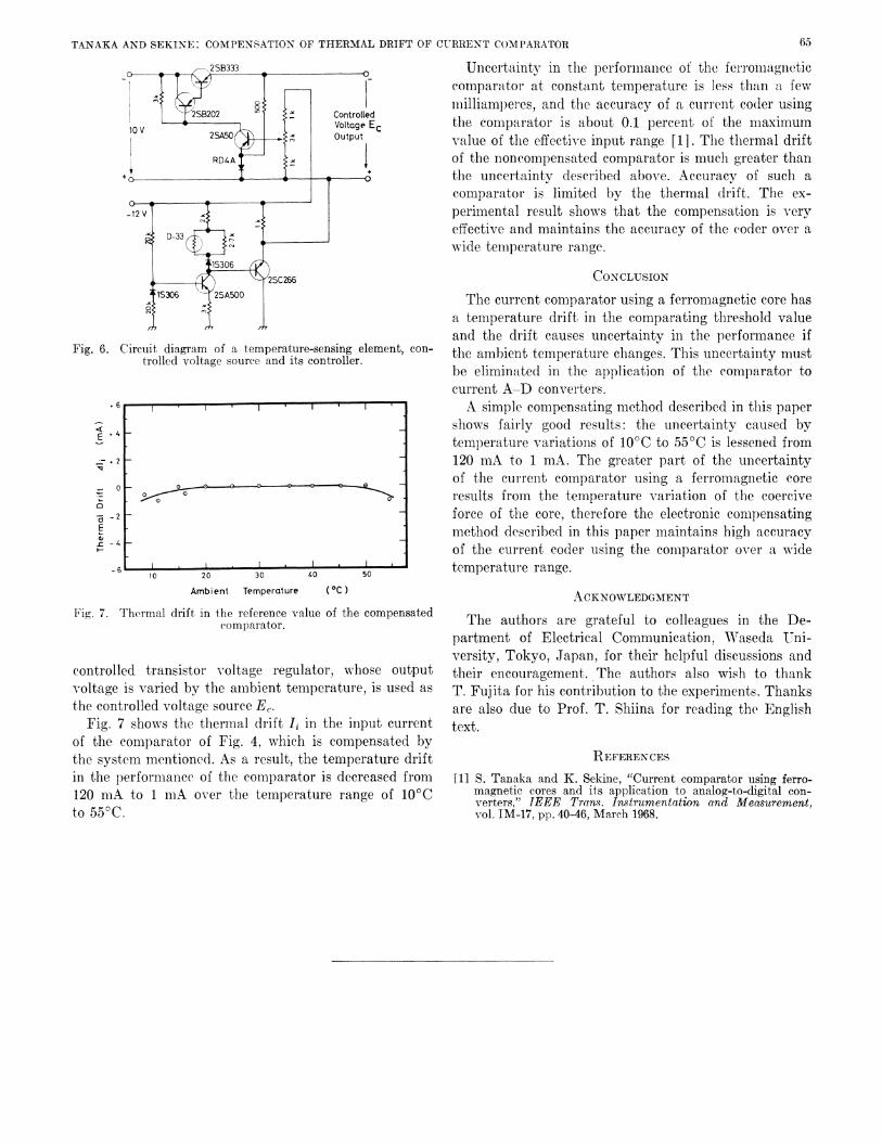
Fig. 7. Thermal drift in the reference value of the compensatedcomparator.
controlled transistor oltage regulator, whose outputvoltage is varied by the amnbient temperature, is used as
the controlled voltage source EC.Fig. 7 shows the thermal drift Ii in the input current
of the comparator of Fig. 4, which is compensated bythe system mentioned. As a result, the temperature driftin the performance of the comparator is decreased from120 mA to 1 mA over the temperature range of 10CCto 550C.
Uncertainty in thie performance of the ferromiiagnieticcomparator at constant temperature is less than a fewmilliamperes, and the accuracy of a current co(ler usingthe comparator is about 0.1 percent of the maximumvalue of the effective input range [1]. The tlhermal driftof the noncompensated comparator is muclh greater thanthe uncertainty described above. Accuracy of such acomparator is limited by the thermal drift. The ex-perimental result shows that the compensation is veryeffective and maintains the accuracy of the coder over awide temperature range.
CONCLUSION
The current comparator using a ferromagnetic core hasa temperature drift in the comparating threshold valueand the drift causes uncertainty in the performance ifthe ambient teinperature changes. This uncertainty mnustbe eliminated in the application of the comparator tocurrent A-D converters.A simple compensating method described in this paper
shows fairly good results: the uncertainty caused bytemperature variations of 10°C to 55°C is lessened from120 mA to 1 mA. The greater part of the uncertaintyof the current comparator using a ferromagnetic coreresults from the temperature variation of the coerciveforce of the core, therefore the electronic comp)ensatingmethod described in this paper mnaintains high accuracyof the current coder using the comparator over a widetemperature range.
ACKNOWLEDGMENT
The authors are grateful to colleagues in the De-partment of Electrical Communication, Waseda Uni-versity, Tokyo, Japan, for their helpful discussions andtheir encouragement. The authors also wish to thankT. Fujita for his contribution to the experiments. Thanksare also due to Prof. T. Shiina for reading the Englishtext.
REFEREN CES[1] S. Tanaka and K. Sekine, "Current comparator using ferro-
magnetic cores and its application to analog-to-digital con-verters," IEEE Trans. Instrumentation and Measuremtent,vol. IM-17, pp. 40-46, March 1968.
o 0a
- 2 L
-4
~~~~~~~~~~~~~~~~I-6 c rN
6 .
65
50