Embed Size (px)
Citation preview
A Method for Model Based Test Harness Generation
for Component Testing
Camila Ribeiro Rocha and Eliane Martins
Institute of Computing State University of Campinas
P.O Box 6176 – Campinas – SP – Brazil – ZC: 13083-970 Phone: +55 (19) 3521-5847 (FAX)
[email protected], [email protected]
Abstract
We present a model-based testing approach that allows the automatic generation of test artifacts for component testing. A component interacts with its clients through provided interfaces, and request services from other components through its required interfaces. Generating a test artifact that acts as though it were the client of the component under test is the easiest part, and there already exists tools to support this task. But one needs also to create substitute of the server components, which is the hardest part. Although there are also tools to help with this task, it still requires manual effort. Our approach provides a systematic way to obtain such substitute components during test generation. Results of the application of the approach in a real world component are also presented.
Keywords: Component testing, Model based testing, Stubs, Test Case Generation.
1. INTRODUCTIONComponent-based Software Engineering (CBSE)
is a process of developing software systems by assembling reusable components. Components may be delivered as single entities that provide, through well-defined interfaces, some functionality required
by the system they integrate. Their services can be accessed through provided interfaces. The operations the component depends on are part of requiredinterfaces. Components may be written in different programming languages, executed in different platforms and may be distributed across different machines. Reusable components may be developed in-house, obtained from existing applications or may be third-party or COTS (from Common Off The Shelf), whose source code might not be available.
The existence of reusable components may significantly reduce development costs and shorten development time. However, the use of existing components is no guarantee that the system will present the required quality attributes. To ensure software quality, among other things, a system must be adequately tested. Moreover, components must be tested each time they are integrated in a new system [34].
Since tests are to be repeated many times, components have to be testable. Briefly speaking, testability is a quality that indicates how hard it is to test a component. The lower the testability the greater the effort required for testing a component. Testability is not only related to the ease of obtaining information necessary to test a component. It also refers to the construction of a generic and reusable test support capability [17].
Camila Ribeiro Rocha A method for model based test harnessand Eliane Martins generation for component testing
8
Test support capabilities comprise, among other things, test case generation in a systematic manner, preferably with the use of tools [18, Ch. 5]. Given the diversity of languages and technologies used in component development, the construction of this support is still a challenge.
Also important is a systematic way to create and maintain test artifacts such as test drivers and stubs. A test driver is a client of the component under test (CUT) exercising the functions of the provided interface. A stub, on the other hand, replaces components that are required by the CUT. Given that test case generation is still predominantly a manual task, the same is true for test artifacts creation, especially the stubs, which are created in an ad-hoc manner and are generally component specific. When component modifications are frequent during development, as is the case in incremental development, this ad-hoc approach is very expensive and inefficient.
In a previous work we focused on the construction of a testable component [30]. In this paper our interest lies in the systematic creation of test cases and test harness (test driver and stubs) for the testable component. We propose a method for test case generation based on UML models. One advantage of the model driven approach is the possibility to automate test case generation. Another advantage is that test cases can be developed, as well as test harness, as soon as the component behavior is specified, which allows their design and specification to occur in parallel to the component implementation.
There are various approaches for test case generation from UML models, for example [4, 9, 14]. However, they do not focus on test stubs generation; on the contrary, the overall recommendation is that they should be avoided or reduced to a minimum [8], [10]. However, there are some situations where stubs are unavoidable. For example, in test-driven development [5], one first writes the tests and then writes the code that implements the tested scenarios, the required external components may not be available yet. Another situation is testing exception handling mechanisms, for faulty situations are often hard to simulate.
In this study we present how to generate test cases and the stubs necessary to run them to completion, from UML activity diagrams, that models the component under test behavior. The model represents both normal and exceptional behaviors, allowing test case generation for exception handling mechanisms.
The test generation method presented here is part of MDCE+ (Methodology for the Definition of Exception Behavior) [12], a development process for component-
based systems which aims at building fault-tolerant, testable components. Besides test generation, MDCE+ also includes guidelines for component testability improvement. It is worth noting that our approach can be used either by the component provider or by its users since the model from which test cases are derived does not contain any internal details about the component.
The rest of the paper is organized as follows: Section 2 explains the concepts of test harness, especially test cases and stubs. Section 3 briefly describes the system used in the examples in this paper. Section 4 describes the steps to define component’s behavior Activity Diagram and to generate test cases and stubs, detailing each phase. Section 5 presents an evaluation of the proposed method, describing a case study and its results. Section 6 compares our proposal with previous work on test case generation and stubs implementation. Section 7 concludes the paper and proposes future work.
2. TEST HARNESS DESIGNA test harness is a system that supports automated
testing. Among the capabilities a test harness provides, we may mention test environment setup, test execution, result logging and analysis [8, Ch 19.1]. The implementation under test may be a single class or procedure, a subsystem or an entire application.
The main elements of a test harness are drivers and stubs, which replace the clients and the servers of the CUT, respectively.
The driver coordinates test execution, performing several services [6, Ch 13.6]: it initializes test cases, interacts with the CUT by sending it test inputs and collecting the outcomes, verifies whether the tests covered required objectives, and reports failed test cases. Test cases can be composed into test suites, a collection of test cases that serves a particular test objective. When a test suite is executed, all of its test cases are run. Test execution results can be stored in a test log. The driver also controls the test suite execution.
Nowadays there are a number of tools available to support driver construction based on the CUT’s provided interface. The well-known JUnit1, from Beck and Gamma, which provides a framework and a tool for unit testing of Java programs, is an example. In Maricks page2 there are links to commercial and open source test drivers. Also, Robert Binder’s book provides various patterns for the design of drivers for object oriented testing [8, Ch. 19.4].
1 http://www.junit.org 2 http://www.testingcraft.com/automation-code-interface.html
Camila Ribeiro Rocha A method for model based test harnessand Eliane Martins generation for component testing
9
It may happen that the CUT depends on components that cannot be used during test case execution. In this case, these components can be replaced by others that do not behave as the real one, but offer the same interfaces.
There are various reasons to replace a real required component, designated here as a server component, by a substitute [8, Ch. 19.3; 25]:
�� the server component is not available, either because it has not been developed or integrated with the CUT yet. This situation may happen during unit testing or incremental integration testing.
�� the server component does not return the results required by the test case or would cause undesirable side effects.
�� some parts of the CUT remain untested due to the inability to control its indirect inputs. An indirect input is data returned by a server component that affects the CUT behavior.
�� CUT’s outcomes that affect its servers, but are not seen through its interface. These are designated as indirect outputs, and may be messages sent through a communication media, for example.
�� a test case would take too long to run when a real server is used such that it is more interesting to use a substitute component to allow tests to run more quickly.
The use of substitute components is not simple. First of all, they are generally produced by hand; therefore, time and effort to construct them is non negligible. The same being true with their maintenance, as they are too many, since they are test case specific. Besides, when the interface of a real server component changes often, their corresponding substitute must also be modified accordingly. Also, the CUT, in some cases, can no longer be treated as a black box, as one may have to know the call sequences within its operations [32]. This may be a problem when testing COTS, whose source code may not be available. Another important point is that, since the real component behaves differently from its substitutes, it is recommended to reapply the tests to the CUT when it is integrated with its actual servers.
When creation of substitute components is unavoidable, their number should be reduced to a minimum, and various approaches exist with that purpose [10]. The substitutes should also have a minimal implementation to eliminate the introduction or propagation of errors, as well as to reduce the time for testing.
Two types of substitute components are commonly used: stubs and mocks [25]. A stub is used to provide indirect inputs required by a test case. A mock, or mock object [24], was proposed by the Extreme Programming (XP) community to unit testing of objects. Differently from stubs, which are language independent, mocks are intended for object-oriented languages. Another difference is that mocks not only provide indirect inputs to the CUT, but also verify whether the indirect outputs produced by the CUT are as expected [15]. In this text, since we are considering component testing, and we do not make any assumption about component source code, we are concerned with stubs, although we use object-oriented design to represent them. So, from now on, we use the term stub to designate a substitute component.
There are a number of ways to design stubs. A stub may be hard-coded or configurable [25]; the latter case, configuration consists in providing the values to be returned, and is performed during test setup. Stubs may be built either statically or dynamically. A static stub is created, compiled and linked with component under test before test starts [32]. Dynamic stubs are generated at run time, using mechanisms such as runtime reflection. This kind of approach is especially useful when neither source code nor component behavior models are provided.
The literature also presents several patterns for stub design and implementation. For example, R. Binder proposes two patterns: the server and the proxy stub [8, Ch. 19.3]. The server stub completely replaces the real component, whereas the proxy stubcan delegate services to the real object. Also, S. Gorst proposes various idioms to implement stubs, such as the responder and the saboteur stub [19]. The responder stub returns valid indirect inputs to the CUT, while the saboteur returns error conditions or exceptions. For an extensive presentation of patterns for stubs and mocks, G. Meszaros home page3 is a good reference.
We propose a static, model based approach for stub generation. In this way, stubs are independent of implementation code since they are derived from a behavior model of the CUT. The objective is also to reduce the effort to generate the stubs, since they can be produced automatically. In case server components interfaces change, only the model is modified, also reducing stub maintenance effort. Stubs can be produced at the same time as the test cases; in that way, it is easier to configure them to return specific values or exceptions according to the test case needs.
3 http://xunitpatterns.com/Test\%20Double\%20Patterns.html
Camila Ribeiro Rocha A method for model based test harnessand Eliane Martins generation for component testing
10
3. EXAMPLE DESCRIPTIONThe remainder of this paper uses as example a steam
boiler controller specification proposed in [2], which is part of a coal mine shaft. The implementation used was developed by Guerra [21] and is based on the C2 architectural style [33]. In C2, the system is structured in layers, where requests flow up the architecture and the corresponding responses (notifications) flow down.
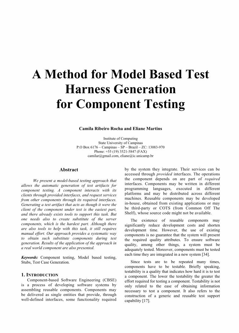
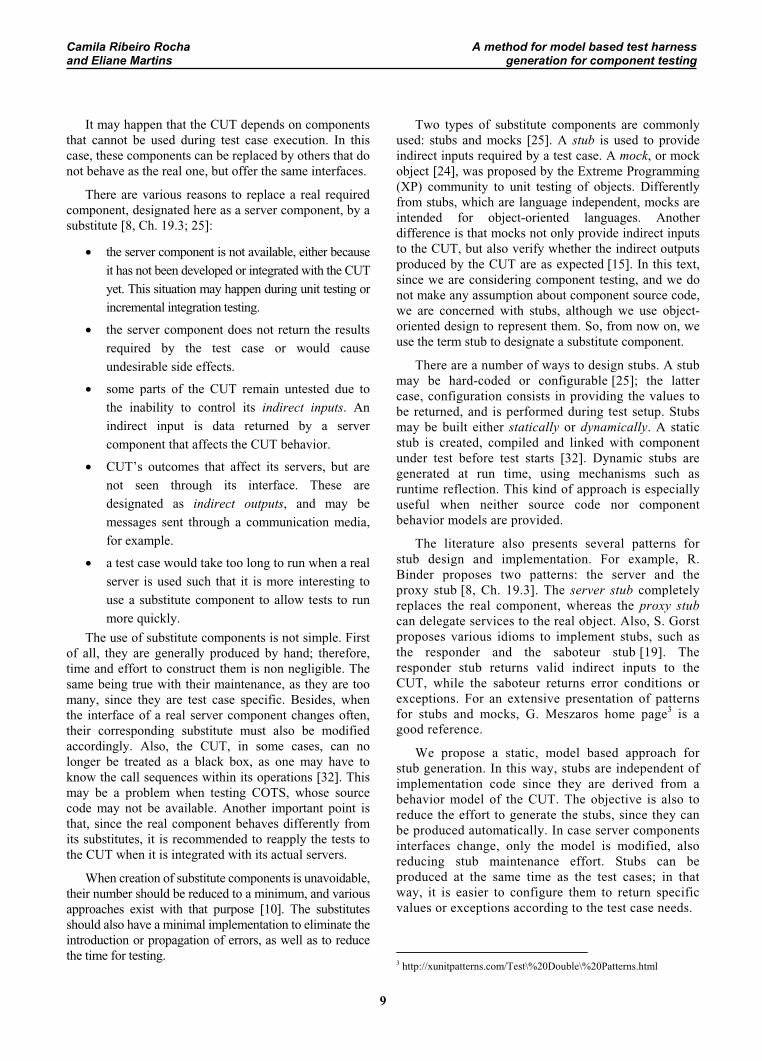
The logical architecture of the system is illustrated in Figure 1, which is structured in four layers. Hardware4
sensors and actuators compose Layer 4; they constitute the COTS components of the system. The layers are integrated through connectors (conn1, conn2 andconn3) responsible for message routing, broadcasting and filtering. According to the C2 architectural style, conn3 is considered a system boundary, as well as the BoilerController component (Layer 1), which is responsible for user interaction.
Figure 1: Steam boiler controller architecture.
We take as CUT the AirFlowController,responsible for periodically checking if airflow rates are stable and according to the specification, and adjusting the airflow if necessary. It also adjusts the coal feed rate when needed. This component was chosen because it has a great number of exception handling mechanisms, which is suitable to our purposes as the testing method we propose is aimed to test these mechanisms too.
4. A COMPONENT TESTING METHODIn this section we present the artifacts required and
produced by our testing method, and how test harness, especially test stubs, are generated. One objective of the method is to use artifacts produced during MDCE+ development phases to exercise CUT’s scenarios. MDCE+ is based on the UML Components method [13], and its main phases are:
4 In Guerras’s work they were simulated by software.
(i) Requirement specification: normal and exceptional scenarios are described as use cases;
(ii) Component identification: provided interfaces are defined, and then grouped as normal or exceptional components;
(iii) Component interaction: each operation in provided interfaces is analyzed in terms of required services, using Activity Diagrams to map the required operations;
(iv) Final component specification: normal and exceptional interfaces are refactored in order to reduce the number of interfaces; an Activity Diagram is defined for each provided interface, describing the execution flow of its operations based on requirements produced in phase (i);
(v) Provisioning: components are selected (or individually implemented) and tested;
(vi) Assembling: components are integrated and tested as a system.
Testing activities start mainly at the end of Final Component Specification phase (v), when component models reach stability. The method is intended for component unit testing and uses the models produced in earlier phases for test generation. The interactions specified in phase (iii) present an architectural view of the system, showing the interaction behavior among the components through their provided and required interfaces. The execution flow specified in phase (iv) defines CUT’s usage scenarios.
In order to be usable in practice, MDCE+ is entirely based on UML, as UML is widely used. UML offers various notations to represent different aspects of a system. To represent system or component behavior, the most used models are the interaction diagrams, mainly the Sequence Diagram, which focus on messages between objects or components of the system; also, State Machines, which represent component behavior in terms of its states and transitions among them. We propose, for testing concerns, the use of Activity Diagrams (AD) to represent component behavior as well as component interaction. The reason is that AD allows representing sequences of execution of operations in a way that is closer to the control flow representation of programs, used in structural testing techniques. In this way, control flow analysis techniques can be used for test case generation purposes at the behavioral level.
The testing method includes the following steps: (i) convert the AD into a graph; (ii) select paths to exercise from this graph; (iii) specify the test cases corresponding
Camila Ribeiro Rocha A method for model based test harnessand Eliane Martins generation for component testing
11
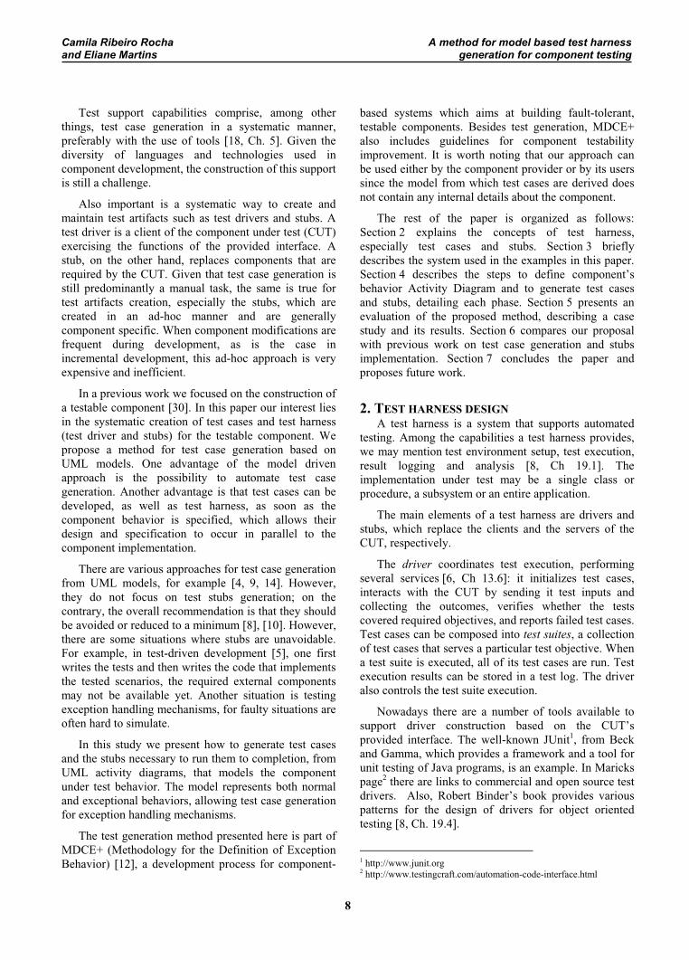
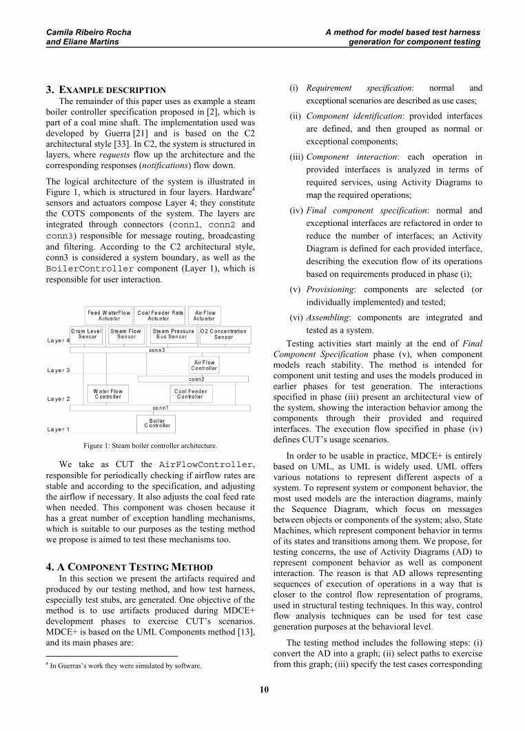
to each selected path; (iv) identify data inputs needed to cause each scenario path to be taken; (v) implement the test cases in the programming language of choice. Figure 2 presents the artifacts used in each step.
Some steps of the method are being automated, such
as the graph generation from the set of Activity Diagrams, as well as test case generation [29]. In the following we give a brief presentation of the AD model that serves as test model; and we describe the steps of our test method.
Figure 2: Test artifacts used in each step of the proposed method.
4.1. THE TEST MODELThe model used to represent CUT’s behavior is the
UML Activity Diagram (AD), a flowchart representing one or more threads of execution. The AD was chosen because it allows representing control flow between activities performed by a component in a form that is easy to use for both developers and testers. It is easy for developers because it is an evolution of flowchart diagrams, which have been used for years to specify functional design. From the tester’s point of view, it allows control flow analysis, used for many years in structural testing, to be applied.
The AD we use for testing purposes is a subset of UML 2.0 [27], as it offers more resources than previous versions, especially with regard to the representation of exceptional behavior. The subset chosen allows the representation of actions and the control flow among them. Actions are points in the flow of an activity that executes a behavior. An operation is represented by a behavior, through its signature. An action can be decomposed into a complete diagram representing the next level of hierarchical behavior. Also, the interaction among components interfaces may be represented by the use of partitions.
For our testing method, control flow specifies sequential behavior: an action can only start execution after the preceding one has finished. Control flow among actions involves conditionals, loops and exception handling. Concurrency and object flow may be represented by AD’s, but these are not covered for the moment.
We also assume that a component has a well defined interface clearly separated from the implementation. In this way, abstract test cases can be derived independently of implementation details.
The AD is then used in this study to specify only the external behavior of the component, in terms of its interface(s) operations and exceptions. Like in other
related works [9, 14, 34], our approach also uses control flow to represent a component usage scenario, which corresponds to valid sequences of the operations of the component provided interfaces. The scenarios may be either normal or exceptional, since a component may throw exceptions to abort the current sequence of operations.
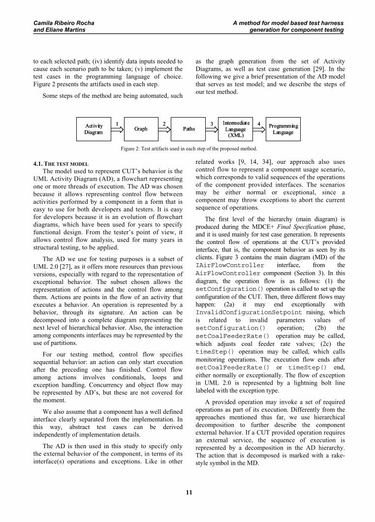
The first level of the hierarchy (main diagram) is produced during the MDCE+ Final Specification phase, and it is used mainly for test case generation. It represents the control flow of operations at the CUT’s provided interface, that is, the component behavior as seen by its clients. Figure 3 contains the main diagram (MD) of the IAirFlowController interface, from the AirFlowController component (Section 3). In this diagram, the operation flow is as follows: (1) the setConfiguration() operation is called to set up the configuration of the CUT. Then, three different flows may happen: (2a) it may end exceptionally with InvalidConfigurationSetpoint raising, which is related to invalid parameters values of setConfiguration() operation; (2b) the setCoalFeederRate() operation may be called, which adjusts coal feeder rate valves; (2c) the timeStep() operation may be called, which calls monitoring operations. The execution flow ends after setCoalFeederRate() or timeStep() end, either normally or exceptionally. The flow of exception in UML 2.0 is represented by a lightning bolt line labeled with the exception type.
A provided operation may invoke a set of required operations as part of its execution. Differently from the approaches mentioned thus far, we use hierarchical decomposition to further describe the component external behavior. If a CUT provided operation requires an external service, the sequence of execution is represented by a decomposition in the AD hierarchy. The action that is decomposed is marked with a rake-style symbol in the MD.
ActivityDiagram Graph Paths
IntermediateLanguage
(XML)
ProgrammingLanguage
1 3 42ActivityDiagram Graph Paths
IntermediateLanguage
(XML)
ProgrammingLanguage
1 3 42
Camila Ribeiro Rocha A method for model based test harnessand Eliane Martins generation for component testing
12
void setConfiguration(P_ref: double, O2_ref: double)
void setCoalFeedRate(C_fr: double) void timeStep()
InvalidConfigurationSetpoint
InvalidO2Concentration
InvalidCoalFeederRate
CoalFeederRateOscillating
AirFlowRateOscillating
InvalidAirFlowRateAirFlowRateOscillating
Start node
Exception
Structured Activity
End Node
Figure 3: Main diagram of the IAirFlowController interface.
Some authors use a gray box approach to represent the behavior of an operation in terms of an UML interaction diagram, mainly, the Sequence Diagram (e.g. [9]). This approach is considered gray box since it represents details about how the component works in terms of objects that compose it. Our approach, on the other hand, is strictly black box as the behavior of an operation is specified in terms of a control flow representation with sequences, loops and alternatives, representing interactions with its required interfaces. No internal details about the component structure are used for that purpose, only the relationships between the required and provided operations. Therefore the hierarchy has only two levels, since the details about the required interfaces are not of interest for CUT testing purposes.
In this way, for each operation represented as structured activities in the first level, there is a second level diagram, which we designate as operation interaction diagrams (OID). Besides describing the interfaces required, the diagrams (MD and OID) also show the parameters of the operations.
These diagrams are recommended as part of MDCE+ Component Interaction phase. At this phase, some details about the exact operations may not be present, such as the exact parameters and their types. Such information must be complemented at the end of the Provisioning phase, where the real components are eventually known.
An OID is created as an activity. This activity may contain formal input and output parameters. Formal input parameters can be checked according to the operation precondition. The output parameters, on the
other hand, may be normal or exceptional data, and they can be checked against the operation postconditions. All end nodes in the interaction diagram can be mapped to flows in the MD.
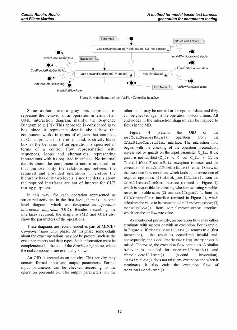
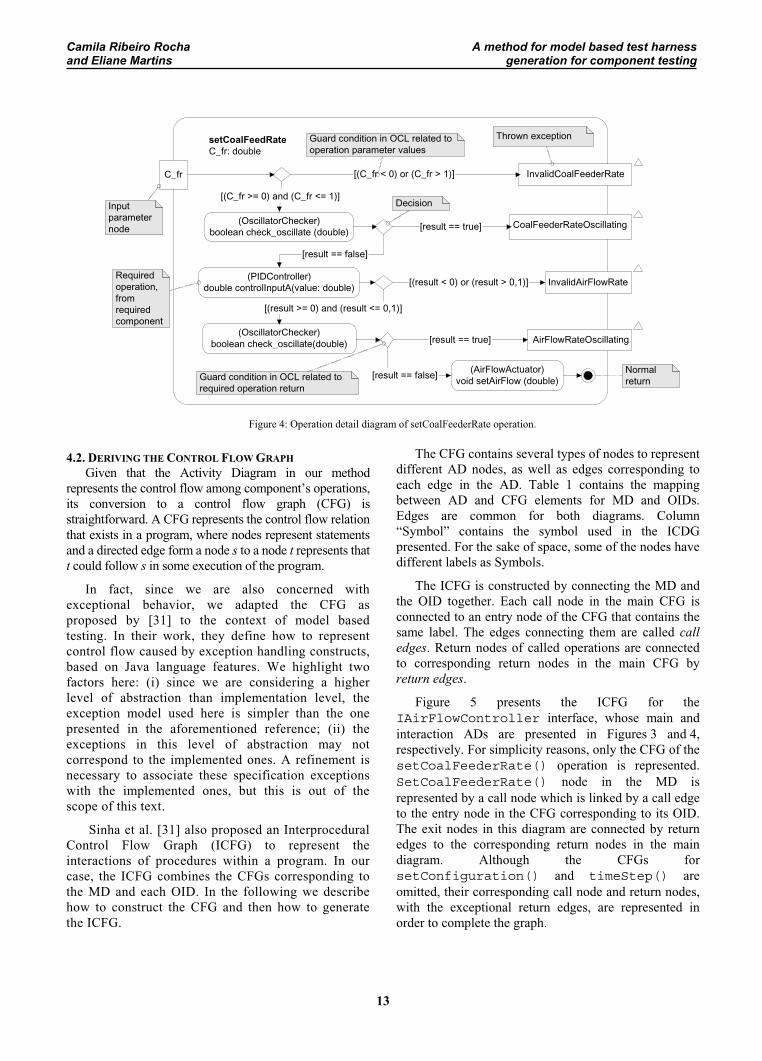
Figure 4 presents the OID of the setCoalFeederRate() operation from the IAirFlowController interface. The interaction flow begins with the checking of the operation precondition, represented by guards on the input parameter, C_fr. If the guard is not satisfied (C_fr < 0 or C_fr > 1), the InvalidCoalFeederRate exception is raised and the execution of setCoalFeederRate() ends. Otherwise, the execution flow continues, which leads to the invocation of required operations: (1) check_oscillate(), from the OscillatorChecker interface (omitted in Figure 1), which is responsible for checking whether oscillating variables revert to a stable state; (2) controlInputA(), from the PIDController interface (omitted in Figure 1), which calculates the value to be passed to AirFlowActuator; (3) setAirFlow(), from AirFlowActuator interface, which sets the air flow rate value.
As mentioned previously, an operation flow may either terminate with success or with an exception. For example, in Figure 4, if check_oscillate() returns true (first invocation), the result is considered invalid and, consequently, the CoalFeederRatingException is raised. Otherwise, the execution flow continues. A similar behavior is modeled for controlInputA() and check_oscillate() (second invocation). SetAirFlow() does not raise any exception and when it terminates it also ends the execution flow of setCoalFeedRate().
Camila Ribeiro Rocha A method for model based test harnessand Eliane Martins generation for component testing
13
CoalFeederRateOscillating
AirFlowRateOscillating
(OscillatorChecker)boolean check_oscillate (double) [result == true]
[result == false]
(OscillatorChecker)boolean check_oscillate(double)
(AirFlowActuator)void setAirFlow (double)[result == false]
[result == true]
(PIDController)double controlInputA(value: double) [(result < 0) or (result > 0,1)]
[(result >= 0) and (result <= 0,1)]
InvalidAirFlowRate
setCoalFeedRateC_fr: double
C_fr InvalidCoalFeederRate[(C_fr < 0) or (C_fr > 1)]
[(C_fr >= 0) and (C_fr <= 1)]Inputparameternode
Decision
Thrown exceptionGuard condition in OCL related tooperation parameter values
Requiredoperation,fromrequiredcomponent
NormalreturnGuard condition in OCL related to
required operation return
Figure 4: Operation detail diagram of setCoalFeederRate operation.
4.2. DERIVING THE CONTROL FLOW GRAPHGiven that the Activity Diagram in our method
represents the control flow among component’s operations, its conversion to a control flow graph (CFG) is straightforward. A CFG represents the control flow relation that exists in a program, where nodes represent statements and a directed edge form a node s to a node t represents that t could follow s in some execution of the program.
In fact, since we are also concerned with exceptional behavior, we adapted the CFG as proposed by [31] to the context of model based testing. In their work, they define how to represent control flow caused by exception handling constructs, based on Java language features. We highlight two factors here: (i) since we are considering a higher level of abstraction than implementation level, the exception model used here is simpler than the one presented in the aforementioned reference; (ii) the exceptions in this level of abstraction may not correspond to the implemented ones. A refinement is necessary to associate these specification exceptions with the implemented ones, but this is out of the scope of this text.
Sinha et al. [31] also proposed an Interprocedural Control Flow Graph (ICFG) to represent the interactions of procedures within a program. In our case, the ICFG combines the CFGs corresponding to the MD and each OID. In the following we describe how to construct the CFG and then how to generate the ICFG.
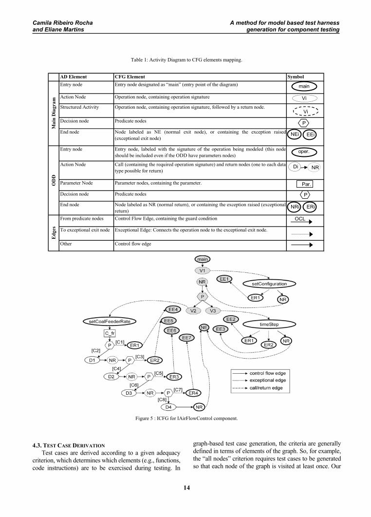
The CFG contains several types of nodes to represent different AD nodes, as well as edges corresponding to each edge in the AD. Table 1 contains the mapping between AD and CFG elements for MD and OIDs. Edges are common for both diagrams. Column “Symbol” contains the symbol used in the ICDG presented. For the sake of space, some of the nodes have different labels as Symbols.
The ICFG is constructed by connecting the MD and the OID together. Each call node in the main CFG is connected to an entry node of the CFG that contains the same label. The edges connecting them are called call edges. Return nodes of called operations are connected to corresponding return nodes in the main CFG by return edges.
Figure 5 presents the ICFG for the IAirFlowController interface, whose main and interaction ADs are presented in Figures 3 and 4, respectively. For simplicity reasons, only the CFG of thesetCoalFeederRate() operation is represented. SetCoalFeederRate() node in the MD is represented by a call node which is linked by a call edge to the entry node in the CFG corresponding to its OID. The exit nodes in this diagram are connected by return edges to the corresponding return nodes in the main diagram. Although the CFGs for setConfiguration() and timeStep() are omitted, their corresponding call node and return nodes, with the exceptional return edges, are represented in order to complete the graph.
Camila Ribeiro Rocha A method for model based test harnessand Eliane Martins generation for component testing
14
Table 1: Activity Diagram to CFG elements mapping.
Figure 5 : ICFG for IAirFlowControl component.
4.3. TEST CASE DERIVATIONTest cases are derived according to a given adequacy
criterion, which determines which elements (e.g., functions, code instructions) are to be exercised during testing. In
graph-based test case generation, the criteria are generally defined in terms of elements of the graph. So, for example, the “all nodes” criterion requires test cases to be generated so that each node of the graph is visited at least once. Our
AD Element CFG Element SymbolEntry node Entry node designated as “main” (entry point of the diagram)
Action Node Operation node, containing operation signature
Structured Activity Operation node, containing operation signature, followed by a return node.
Decision node Predicate nodes
End node Node labeled as NE (normal exit node), or containing the exception raised(exceptional exit node)
Entry node Entry node, labeled with the signature of the operation being modeled (this nodeshould be included even if the ODD have parameters nodes)
Action Node Call (containing the required operation signature) and return nodes (one to each datatype possible for return)
Parameter Node Parameter nodes, containing the parameter.
Decision node Predicate nodes
End node Node labeled as NR (normal return), or containing the exception raised (exceptionalreturn)
From predicate nodes Control Flow Edge, containing the guard condition
To exceptional exit node Exceptional Edge: Connects the operation node to the exceptional exit node.
Other Control flow edge
Mai
n D
iagr
amO
DD
Edge
s
main
Vi
Vi
P
NEi
oper.
Di NR
Par.
P
NRi
OCL
EEi
ERi
Camila Ribeiro Rocha A method for model based test harnessand Eliane Martins generation for component testing
15
goal is to satisfy the “all-edges” test criterion. In this criterion, every edge is covered at least once. We choose this criterion because it is easy to implement; for example, a depth-first search algorithm (DFS) can be used for that purpose. Also, its error detection capabilities are better than the “all nodes” criterion.
Another concern of the approach is the derivation of test cases that are independent of each other. This is recommended since they are easier to execute and maintain. For that purpose, we adopt a path-oriented test case generation, where paths are obtained from the graph until the criterion is satisfied. A path is a sequence of edges from an origin to a destination node. Our interest is in complete paths, that is, paths starting at the main entry node and ending at an exit node of the ICFG.
One problem that we have to cope with is the existence of loops (or cycles in the graph). We do not address this problem here; we consider only loop-free paths [6], where no node or edge is repeated in the path. Of course, criteria that cover loops should also be considered in the future, but for now, our concern is to present how to derive test cases using a hierarchy of ADs and to show the viability of the approach.
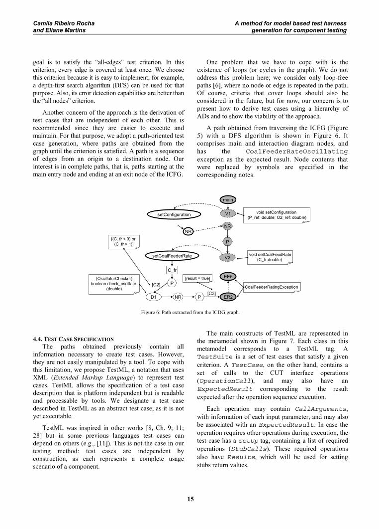
A path obtained from traversing the ICFG (Figure 5) with a DFS algorithm is shown in Figure 6. It comprises main and interaction diagram nodes, and has the CoalFeederRateOscillatingexception as the expected result. Node contents that were replaced by symbols are specified in the corresponding notes.
Figure 6: Path extracted from the ICDG graph.
4.4. TEST CASE SPECIFICATIONThe paths obtained previously contain all
information necessary to create test cases. However, they are not easily manipulated by a tool. To cope with this limitation, we propose TestML, a notation that uses XML (Extended Markup Language) to represent test cases. TestML allows the specification of a test case description that is platform independent but is readable and processable by tools. We designate a test case described in TestML as an abstract test case, as it is not yet executable.
TestML was inspired in other works [8, Ch. 9; 11; 28] but in some previous languages test cases can depend on others (e.g., [11]). This is not the case in our testing method: test cases are independent by construction, as each represents a complete usage scenario of a component.
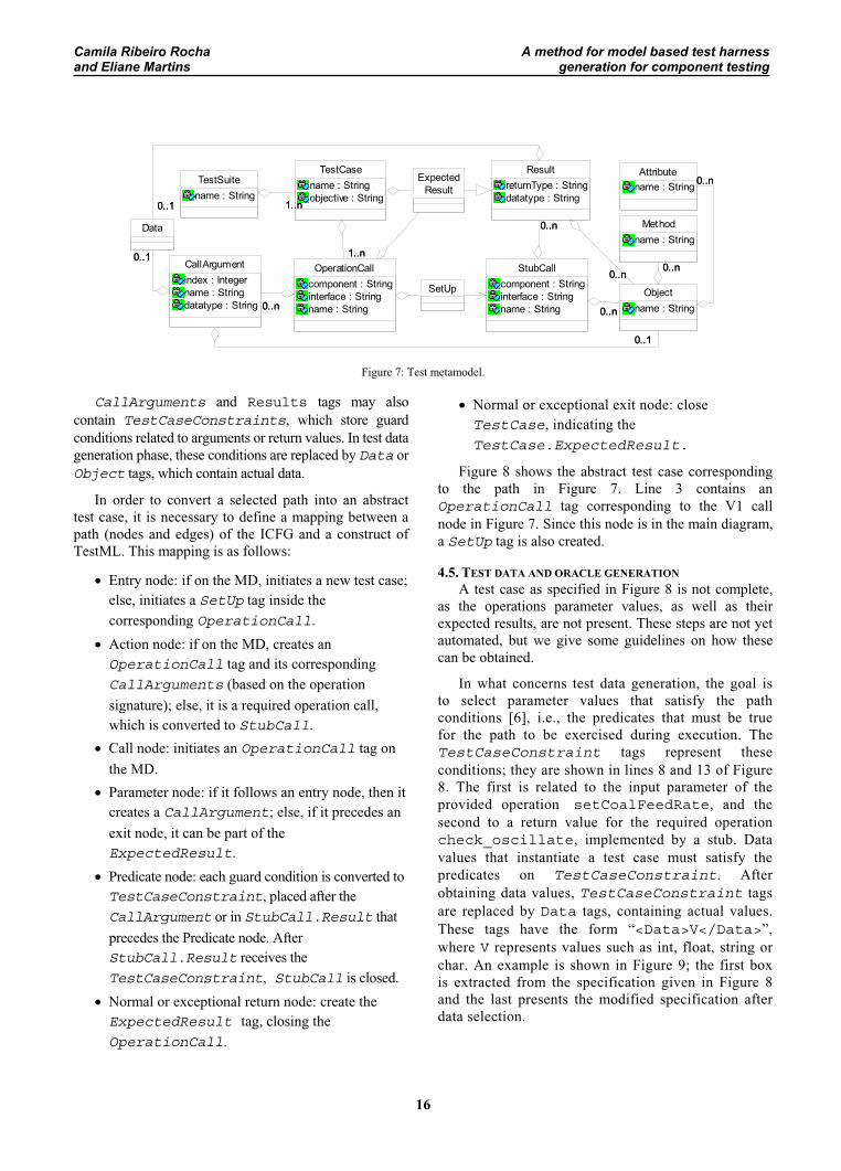
The main constructs of TestML are represented in the metamodel shown in Figure 7. Each class in this metamodel corresponds to a TestML tag. A TestSuite is a set of test cases that satisfy a given criterion. A TestCase, on the other hand, contains a set of calls to the CUT interface operations (OperationCall), and may also have an ExpectedResult corresponding to the result expected after the operation sequence execution.
Each operation may contain CallArguments,with information of each input parameter, and may also be associated with an ExpectedResult. In case the operation requires other operations during execution, the test case has a SetUp tag, containing a list of required operations (StubCalls). These required operations also have Results, which will be used for setting stubs return values.
setConfiguration
main
V1
EE5
ER2
NRNR
setCoalFeederRate
C_fr
P
D1 NR P
P
V2
[C2]
[C3]
void setConfiguration(P_ref: double; O2_ref: double)
[(C_fr < 0) or (C_fr > 1)]
[result = true](OscillatorChecker)boolean check_oscillate
(double) CoalFeederRatingException
void setCoalFeedRate(C_fr:double)
Camila Ribeiro Rocha A method for model based test harnessand Eliane Martins generation for component testing
16
TestSuitename : String
ExpectedResult
SetUp
TestCasename : Stringobjective : String
1..n1..n
OperationCallcomponent : Stringinterface : Stringname : String
1..n1..n
Methodname : String
Attributename : String
StubCallcomponent : Stringinterface : Stringname : String
Objectname : String
0..n0..n
0..n0..n
0..n0..n
CallArgumentindex : Integername : Stringdatatype : String 0..n0..n
0..10..1
Data
0..1
ResultreturnType : Stringdatatype : String
0..n0..n
0..n0..n
0..1
0..1
0..1
Figure 7: Test metamodel.
CallArguments and Results tags may also contain TestCaseConstraints, which store guard conditions related to arguments or return values. In test data generation phase, these conditions are replaced by Data or Object tags, which contain actual data.
In order to convert a selected path into an abstract test case, it is necessary to define a mapping between a path (nodes and edges) of the ICFG and a construct of TestML. This mapping is as follows:
�� Entry node: if on the MD, initiates a new test case; else, initiates a SetUp tag inside the corresponding OperationCall.
�� Action node: if on the MD, creates an OperationCall tag and its corresponding CallArguments (based on the operation signature); else, it is a required operation call, which is converted to StubCall.
�� Call node: initiates an OperationCall tag on the MD.
�� Parameter node: if it follows an entry node, then it creates a CallArgument; else, if it precedes an exit node, it can be part of the ExpectedResult.
�� Predicate node: each guard condition is converted to TestCaseConstraint, placed after the CallArgument or in StubCall.Result that precedes the Predicate node. After StubCall.Result receives the TestCaseConstraint, StubCall is closed.
�� Normal or exceptional return node: create the ExpectedResult tag, closing the OperationCall.
�� Normal or exceptional exit node: close TestCase, indicating the TestCase.ExpectedResult.
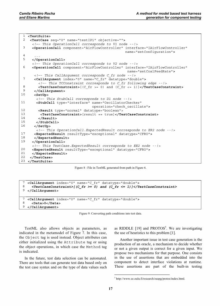
Figure 8 shows the abstract test case corresponding to the path in Figure 7. Line 3 contains an OperationCall tag corresponding to the V1 call node in Figure 7. Since this node is in the main diagram, a SetUp tag is also created.
4.5. TEST DATA AND ORACLE GENERATION A test case as specified in Figure 8 is not complete,
as the operations parameter values, as well as their expected results, are not present. These steps are not yet automated, but we give some guidelines on how these can be obtained.
In what concerns test data generation, the goal is to select parameter values that satisfy the path conditions [6], i.e., the predicates that must be true for the path to be exercised during execution. The TestCaseConstraint tags represent these conditions; they are shown in lines 8 and 13 of Figure 8. The first is related to the input parameter of the provided operation setCoalFeedRate, and the second to a return value for the required operation check_oscillate, implemented by a stub. Data values that instantiate a test case must satisfy the predicates on TestCaseConstraint. After obtaining data values, TestCaseConstraint tags are replaced by Data tags, containing actual values. These tags have the form “<Data>V</Data>”,where V represents values such as int, float, string or char. An example is shown in Figure 9; the first box is extracted from the specification given in Figure 8 and the last presents the modified specification after data selection.
Camila Ribeiro Rocha A method for model based test harnessand Eliane Martins generation for component testing
17
12
3
45
6
7
89
10
11
1213141516
171819
20212223
<TestSuite><TestCase seq="0" name="testIP1" objective=""><!—- This OperationCall corresponds to V1 node --!><OperationCall component="AirFlowController" interface="IAirFlowController"
name="setConfiguration"> ... </OperationCall>
<!—- This OperationCall corresponds to V2 node --!> <OperationCall component="AirFlowController" interface="IAirFlowController" name="setCoalFeedRate"> <!—- This CallArgument corresponds C_fr node --!> <CallArgument index="0" name="C_fr" datatype="double"> <!—- This TCConstraint corresponds to C_fr following edge --!>
<TestCaseConstraint>[(C_fr >= 0) and (C_fr <= 1)]</TestCaseConstraint> </CallArgument> <SetUp> <!—- This StubCall corresponds to D1 node --!>
<StubCall type="interface" name="OscillatorChecker" operation="check_oscillate">
<Result type="normal" datatype="boolean"> <TestCaseConstraint>[result == true]</TestCaseConstraint>
</Result> </StubCall> </SetUp> <!—- This OperationCall.ExpectedResult corresponds to ER2 node --!>
<ExpectedResult resultType="exceptional" datatype="CFRO"> </ExpectedResult> </OperationCall> <!—- This TestCase.ExpectedResult corresponds to EE2 node --!> <ExpectedResult resultType="exceptional" datatype="CFRO"> </ExpectedResult> </TestCase> </TestSuite>
Figure 8 : File in TestML generated from path in Figure 6.
789
<CallArgument index="0" name="C_fr" datatype="double"><TestCaseConstraint>[(C_fr >= 0) and (C_fr <= 1)]</TestCaseConstraint>
</CallArgument>
789
<CallArgument index="0" name="C_fr" datatype="double"><Data>0</Data>
</CallArgument>
Figure 9: Converting path conditions into test data.
TestML also allows objects as parameters, as indicated in the metamodel of Figure 7. In this case, the Object tag is used instead. Object attributes can either initialized using the Attribute tag or using the object operations, in which case the Method tag is indicated.
In the future, test data selection can be automated. There are tools that can generate test data based only on the test case syntax and on the type of data values such
as RIDDLE [19] and PROTOS5. We are investigating the use of heuristics to this problem [1].
Another important issue in test case generation is the production of an oracle, a mechanism to decide whether or not a given output is correct for a given input. We propose two mechanisms for that purpose. One consists in the use of assertions that are embedded into the component to detect interface violations at runtime. These assertions are part of the built-in testing
5 http://www.ee.oulu.fi/research/ouspg/protos/index.html.
Camila Ribeiro Rocha A method for model based test harnessand Eliane Martins generation for component testing
18
capabilities of a testable component [30]. The ExpectedResult tags of TestML provide the other oracle mechanism. In this case, test analysts fill the expected outputs manually. The operation postcondition, when stated in the specification, can also be used to guide this task.
4.6. IMPLEMENTATION ISSUESIn this section we present the guidelines on how to
convert test cases in TestML to an executable form. For this example we considered test cases implemented in Java, based in the JUnit framework.
The test architecture is composed of four main elements: the driver (which is derived from the TestSuite class of the JUnit framework), the test cases (which are subclasses of the JUnit TestCaseclass), the CUT and the stubs (which implement the CUT’s required interfaces).
In the following we describe how test cases and stubs are implemented from the TestML specification.
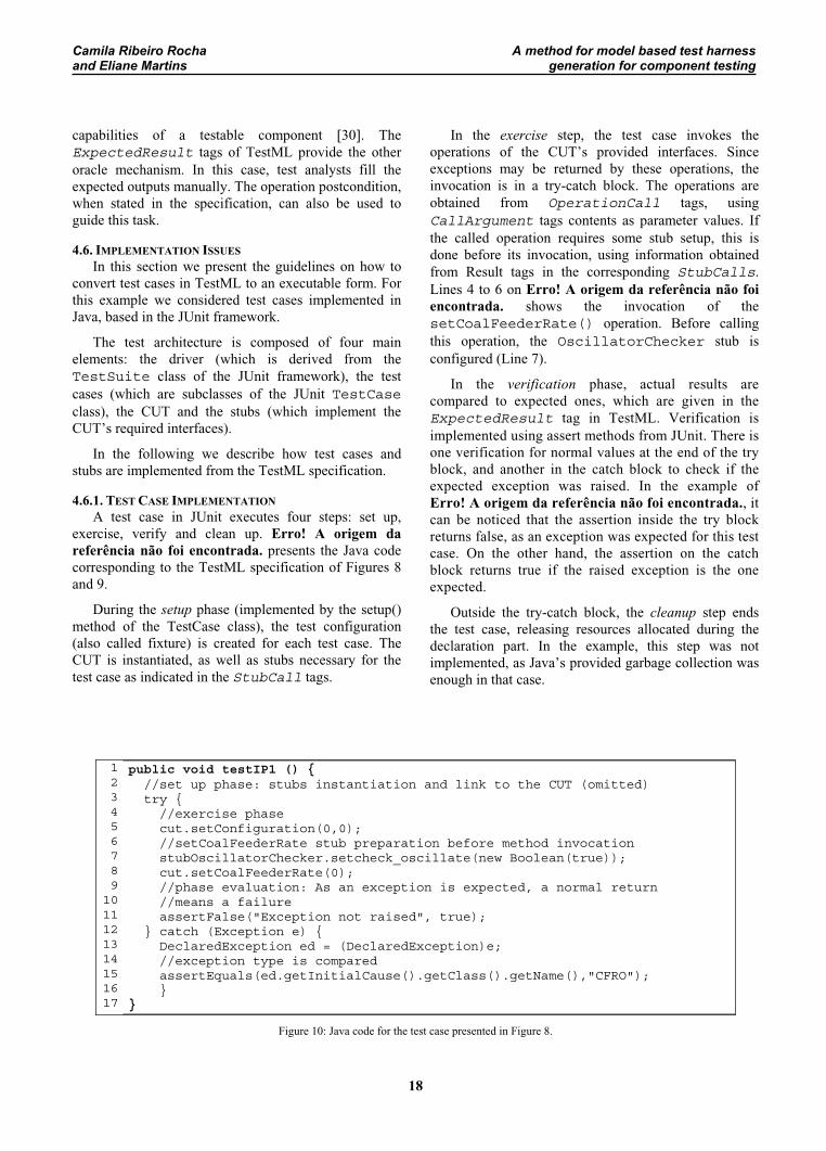
4.6.1. TEST CASE IMPLEMENTATIONA test case in JUnit executes four steps: set up,
exercise, verify and clean up. Erro! A origem da referência não foi encontrada. presents the Java code corresponding to the TestML specification of Figures 8 and 9.
During the setup phase (implemented by the setup() method of the TestCase class), the test configuration (also called fixture) is created for each test case. The CUT is instantiated, as well as stubs necessary for the test case as indicated in the StubCall tags.
In the exercise step, the test case invokes the operations of the CUT’s provided interfaces. Since exceptions may be returned by these operations, the invocation is in a try-catch block. The operations are obtained from OperationCall tags, using CallArgument tags contents as parameter values. If the called operation requires some stub setup, this is done before its invocation, using information obtained from Result tags in the corresponding StubCalls.Lines 4 to 6 on Erro! A origem da referência não foi encontrada. shows the invocation of the setCoalFeederRate() operation. Before calling this operation, the OscillatorChecker stub is configured (Line 7).
In the verification phase, actual results are compared to expected ones, which are given in the ExpectedResult tag in TestML. Verification is implemented using assert methods from JUnit. There is one verification for normal values at the end of the try block, and another in the catch block to check if the expected exception was raised. In the example of Erro! A origem da referência não foi encontrada., it can be noticed that the assertion inside the try block returns false, as an exception was expected for this test case. On the other hand, the assertion on the catch block returns true if the raised exception is the one expected.
Outside the try-catch block, the cleanup step ends the test case, releasing resources allocated during the declaration part. In the example, this step was not implemented, as Java’s provided garbage collection was enough in that case.
1234
5 6789
1011121314151617
public void testIP1 () { //set up phase: stubs instantiation and link to the CUT (omitted) try { //exercise phase cut.setConfiguration(0,0); //setCoalFeederRate stub preparation before method invocation stubOscillatorChecker.setcheck_oscillate(new Boolean(true)); cut.setCoalFeederRate(0); //phase evaluation: As an exception is expected, a normal return //means a failure assertFalse("Exception not raised", true); } catch (Exception e) { DeclaredException ed = (DeclaredException)e; //exception type is compared assertEquals(ed.getInitialCause().getClass().getName(),"CFRO"); } }
Figure 10: Java code for the test case presented in Figure 8.
Camila Ribeiro Rocha A method for model based test harnessand Eliane Martins generation for component testing
19
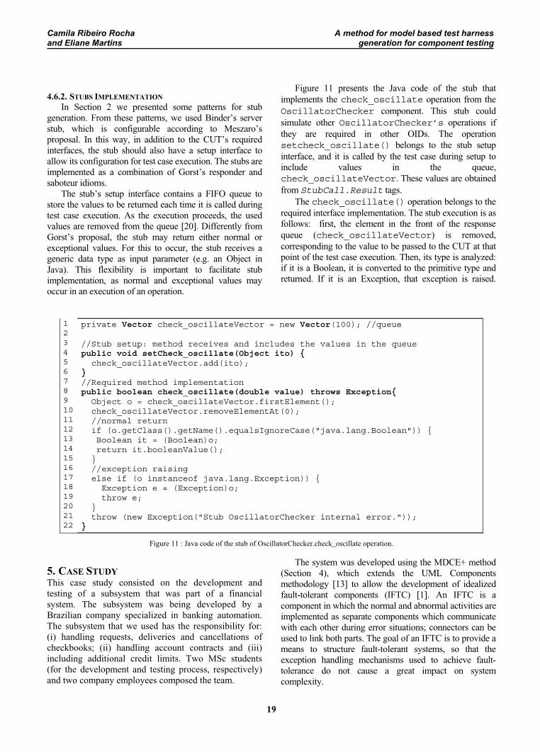
4.6.2. STUBS IMPLEMENTATIONIn Section 2 we presented some patterns for stub
generation. From these patterns, we used Binder’s server stub, which is configurable according to Meszaro’s proposal. In this way, in addition to the CUT’s required interfaces, the stub should also have a setup interface to allow its configuration for test case execution. The stubs are implemented as a combination of Gorst’s responder and saboteur idioms.
The stub’s setup interface contains a FIFO queue to store the values to be returned each time it is called during test case execution. As the execution proceeds, the used values are removed from the queue [20]. Differently from Gorst’s proposal, the stub may return either normal or exceptional values. For this to occur, the stub receives a generic data type as input parameter (e.g. an Object in Java). This flexibility is important to facilitate stub implementation, as normal and exceptional values may occur in an execution of an operation.
Figure 11 presents the Java code of the stub that implements the check_oscillate operation from the OscillatorChecker component. This stub could simulate other OscillatorChecker’s operations if they are required in other OIDs. The operation setcheck_oscillate() belongs to the stub setup interface, and it is called by the test case during setup to include values in the queue, check_oscillateVector. These values are obtained from StubCall.Result tags.
The check_oscillate() operation belongs to the required interface implementation. The stub execution is as follows: first, the element in the front of the response queue (check_oscillateVector) is removed, corresponding to the value to be passed to the CUT at that point of the test case execution. Then, its type is analyzed: if it is a Boolean, it is converted to the primitive type and returned. If it is an Exception, that exception is raised.
12345678910111213141516171819202122
private Vector check_oscillateVector = new Vector(100); //queue
//Stub setup: method receives and includes the values in the queue public void setCheck_oscillate(Object ito) { check_oscillateVector.add(ito); }//Required method implementation public boolean check_oscillate(double value) throws Exception{ Object o = check_oscillateVector.firstElement(); check_oscillateVector.removeElementAt(0); //normal return if (o.getClass().getName().equalsIgnoreCase("java.lang.Boolean")) { Boolean it = (Boolean)o; return it.booleanValue(); } //exception raising else if (o instanceof java.lang.Exception)) { Exception e = (Exception)o; throw e; } throw (new Exception("Stub OscillatorChecker internal error.")); }
Figure 11 : Java code of the stub of OscillatorChecker.check_oscillate operation.
5. CASE STUDYThis case study consisted on the development and testing of a subsystem that was part of a financial system. The subsystem was being developed by a Brazilian company specialized in banking automation. The subsystem that we used has the responsibility for: (i) handling requests, deliveries and cancellations of checkbooks; (ii) handling account contracts and (iii) including additional credit limits. Two MSc students (for the development and testing process, respectively) and two company employees composed the team.
The system was developed using the MDCE+ method (Section 4), which extends the UML Components methodology [13] to allow the development of idealized fault-tolerant components (IFTC) [1]. An IFTC is a component in which the normal and abnormal activities are implemented as separate components which communicate with each other during error situations; connectors can be used to link both parts. The goal of an IFTC is to provide a means to structure fault-tolerant systems, so that the exception handling mechanisms used to achieve fault-tolerance do not cause a great impact on system complexity.
Camila Ribeiro Rocha A method for model based test harnessand Eliane Martins generation for component testing
20
Eight IFTCs were developed; four of them to implement system use cases, called system components[13]; and another four to implement data storage services, designated business components. For testing purposes, only system components were chosen as they implement system functionalities. These components are listed in Table 2.
MDCE+ proposes exception handlers reuse, allowing an abnormal component to be part of different IFTCs. If different (system or business) components can raise similar exceptions, their handlers can be grouped in a single abnormal component. An example is the agencyHandlercomponent, which groups all the exceptions related to the agency data type, raised either by business or system components. Using this approach, system components were constructed by combining normal components (a total of four) and exception handlers (a total of nine); these components are listed in Table 3.
Table 2 summarizes our main test results. The number of nodes and edges shows the complexity of each component’s ICFG. The number of generated test cases is also presented, together with the number of failures that occurred during test execution. The number of failures detected by each oracle mechanism, described in Section 4.5, is also indicated. Both mechanisms detected the same failures, except in one case, where the expected result in the test cases detected one more failure. The reason is that the built-in assertions are not good in detecting whether a specific output is produced for a given input, which justifies the verification step in a test case (c.f. 2).
Table 2 : Test execution statistics
Component* ICFG nodes
ICFG edges
TestCases
Failuresdetectedby test cases
Failuresdetectedby built-in self-
checking CaptureCheck Operations
37 51 27 2 2
suspendCheckOperations
50 64 23 2 2
accountOperations
106 135 47 4 3
checkbookOperations
102 140 47 2 2
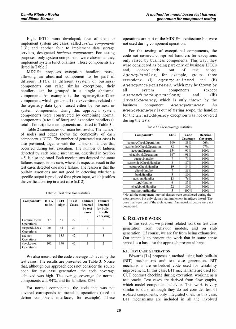
We also measured the code coverage achieved by the test cases. The results are presented on Table 3. Notice that, although our approach does not consider the source code for test case generation, the code coverage achieved was high. The average coverage for normal components was 94%, and for handlers, 83%.
For normal components, the code that was not covered corresponds to metadata operations (used to define component interfaces, for example). These
operations are part of the MDCE+ architecture but were not used during component operation.
For the testing of exceptional components, the code not covered comprised handlers for exceptions only raised by business components. This way, they were considered as being part only of business IFTCs and, consequently, out of test scope. AgencyHandler, for example, groups three exceptions: (i) agencyIsClosed and (ii) agencyNotRegistered, which may be thrown by all system components (except suspendCheckOperations); and (iii) invalidAgency, which is only thrown by the business component AgencyManager. As AgencyManager is out of testing scope, the handler for the invalidAgency exception was not covered during the tests.
Table 3 : Code coverage statistics.
Component* LOC CodeCoverage
DecisionCoverage
captureCheckOperations 109 88% 96% suspendedCheckOperations 88 96% 97%
accountOperations 154 95% 100% checkbookOperations 167 98% 100%
agencyHandler 7 71% 100% suspendedCheckHandler 8 87% 100%
captureCheckHandler 19 84% 100% clientHandler 7 85% 100% bankHandler 5 80% 100%
accountHandler 13 76% 100% typeHandler 6 83% 100%
checkbookHandler 22 80% 100% transactionHandler 5 100% 100%
*Not all the component internal classes were considered during the measurement, but only classes that implement interfaces intead. The ones that were part of the architectural framework structure were not considered.
6. RELATED WORKIn this section, we present related work on test case
generation from behavior models, and on stub generation. Of course, we are far from being exhaustive. Our intent is to present the work that in some sense served as a basis for the approach presented here.
6.1. TEST CASE GENERATIONEdwards [14] proposes a method using both built-in
(BIT) mechanisms and test case generation. BIT mechanisms are embedded code used for testability improvement. In this case, BIT mechanisms are used for CUT contract checking during execution, working as a test oracle. Test cases are derived from flow graphs, which model component behavior. This work is very similar to ours, although they do not consider test of isolated components, only integrated ones. In this case, BIT mechanisms are included in all the involved
Camila Ribeiro Rocha A method for model based test harnessand Eliane Martins generation for component testing
21
components to facilitate fault locations. However, they do not present guidelines for stubs generation. Also, the graph is not obtained from UML models in our method.
Briand and Labiche [9] propose TOTEM (Testing Object-orienTed systEms with the unified Modeling language). Many different models created by development teams are used for test case generation: use cases, interaction diagrams (sequence or collaboration) and class diagrams. Test cases are generated from activity and interaction diagrams, characterizing a gray box testing method, as the class structure of the system must be known. This is the main limitation of TOTEM for component testing, as it cannot always be assumed that a component’s internal structure is available. Our approach, instead, is completely black box, and needs no information about a component’s internal details.
Bundell et al. [11] propose the Component Test Bench tool (CTB) for test case development and execution. This tool offers an editor where a tester can code test cases using a format based on XML. Functionalities like oracle generation and test coverage are also provided. When dealing with COTS components, test specifications and a CTB module are also delivered with the COTS, allowing test cases to be customized and executed in in the client’s environment. However, test case generation facilities are not offered, nor component specification is available to the client. In our case, component specification is packed together with the component, according to the testable component architecture [30]. Besides contributing for client understanding, the specifications are also used for test case generation.
Another difference between our approach and the ones previously mentioned is that ours explicitly considers the testing of exception handling mechanisms.
6.2. TEST STUBSKaiser et. al. [22] present Infuse, a software
development environment that supports testing by aiding users in constructing both drivers and stubs. Infuse supports testing of systems implemented in procedural languages such as C. Headers (in C parlance) for the stubs are automatically generated but their contents must be created by hand or by some external mechanism. The main differences from our approach are that our test cases and stubs are automatically generated from a behavior model, and not from the code, and our test cases and stubs are language independent. Although we present an object-oriented design for test harness, tests are generated in XML and can be converted to any language.
SeDiTeC is a tool that uses Sequence Diagrams (SD) to generate tests for Java programs [16]. Drivers are
produced automatically from SDs representing the behavior of the program under test. Test stubs for selected classes are generated independently of test cases; the stubs communicate with the driver at runtime to know what they are supposed to do. The advantage is that the stubs are regenerated only when the interface of the stubbed class changes. The stub behaves as specified in the SD. In our case, the stubs are test case specific, hence we do not need a behavior model for the component being stubbed.
Lloyd and Malloy [23] present a study for testing objects in the presence of stubs. Their work describes how to construct minimal implementations for stubs, in order to reduce the generation effort. Test cases for a class are obtained from a Method Sequence Graph, which allows the generation of the sequence of method invocations to test a class. However, they do not describe how to produce stubs automatically. Besides, since the stubs cannot throw exceptions, this poses a problem to test exceptionhandling mechanisms.
Bertolino et al. [7] present Puppet (Pick UP Performance Evaluation Test bed) for evaluating Quality of Service (QoS) characteristics of Web Services (WS). Their method provides tools for the automatic generation of a test bed, based on QoS specifications of both the service under test and the interacting services. Stubs are generated in order to replace required services; their generation is based on service description in WSDL, a standard in WS communities, and in service agreements specification. The former is used to generate the stub skeleton, whereas the latter is used to obtain the parameterizable code that simulates the QoS constraints. They also transform XML definitions into Java code. Stubs generation is mostly automatic, however data values are generated randomly. The main difference is that Puppet considers only non functional scenarios (as latency, delay, reliability), and our method exercises functional implementation. Also, the tool is based on WSDL, which constrains the tools to the WS domain, whereas in our case, we are based on a higher level description, which allows our approach to be applied in other domains.
There are also various tools that support test case implementation and execution. JUnit [26] is an example. However, it is not concerned with test case generation. There are also tools to support the creation of mock objects, which may be useful for stub implementation, but generally they have some limitations, as discussed in Section 2. They are generally implementation language dependent, which can be a problem for components that can be written in different programming languages, and whose source code may not be available.
Camila Ribeiro Rocha A method for model based test harnessand Eliane Martins generation for component testing
22
7. CONCLUSIONS AND FUTURE WORKIn this paper we presented a method to generate a
test harness from UML models. The approach can be useful in situations where stubs are unavoidable, like test driven programming and testing of exception handling mechanisms.
The method considers UML activity diagrams, which models component behavior. The component is considered black box, since only its provided and required interfaces are considered. In this way, test cases generated from this model contain information to exercise the component through its provided interfaces, as well as to prepare the stubs replacing the external components required for test case execution.
As both normal and exceptional behaviors were considered, test cases could exercise exception-handling code. In a case study executed in an industrial environment, for an application where more than 2/3 of the code corresponds to exception handling constructions, test coverage was highly satisfactory. For normal components, the average branch coverage achieved was 94%, and for the exceptional ones, the average was 83%. For exception handling mechanisms, high code coverage was achieved mainly because of stubs, allowing the simulation of required components failures. The code not covered, both in normal and abnormal scenarios, were relative to parts not related to the functional behavior (e.g., component architecture configuration) of the components under test.
For a large set of components, it is not possible to create test artifacts for all. We recommended prioritizing the components according to criticality, possibility of reuse, and requirement stability. Components with less priority will be tested during integration and system testing phases. Large components can be treated similarly: only the most critical parts are modeled and tested individually. This should include exception handlers, which usually handles critical functions that are not easily simulated without stubs.
The main advantage of our method is test case generation in a language independent way including exceptional behavior coverage. The method also presents the possibility of stubs creation. The stubs are synchronized with the test cases from UML models, allowing both test cases and stubs to be built early in the development process.
In the future, we intend to address some of the method’s limitations, especially those related to automation. For example, concurrency is an aspect that can be represented in UML Activity diagrams but is not yet addressed, due to the difficulty to generate test paths to cover these situations. Another important aspect is the
generation of test data. It is our intent to provide automated support to the whole process, that is, from building a testable component through test case generation and execution as well as results analysis.
ACKNOWLEDGMENTThe authors wish to acknowledge the support of
CNPq for a MSc fellowship, and the financial support of Finep (1843/04).
REFERENCES[1] B. Abreu et al. Automatic Test Data Generation
for Path Testing using a New Stochastic Algorithm. In Proceedings of 19th Brazilian Symposium on Software Engineering (SBES),Uberlandia, pp. 247-262, 2005.
[2] T. Anderson, P. Lee. Fault Tolerance: Principles and Practice, 2nd edition. Prentice-Hall, 1990.
[3] T. Anderson, et al. Protective wrapper development: A case study. Lecture Notes in Computer Science, 2580: pp. 1–14, 2003.
[4] D. Barbosa et al. Spaces - a tool for component’s functional testing (in portuguese). In Proceedings of XVIII Brazilian Symposium of Software Engineering - XI Tool Session. pp. 55–60, 2004.
[5] K. Beck. Test Driven Development: By Example. Addison-Wesley Longman Publishing Co., Inc., Boston, 2002.
[6] B. Beizer. Sofware Testing Techniques, 2nd Edition. International Thomson Computer Press, 1990.
[7] A. Bertolino, G. De Angelis, A. Polini. A QoS Test-Bed Generator for Web Services. LectureNotes in Computer Science, 4607:17-31, 2007.
[8] R. Binder. Testing object-oriented systems: models, patterns, and tools. Addison-Wesley Longman Publishing Co., Inc, 1999.
[9] L. Briand, Y. Labiche. A uml-based approach to system testing. In Proceedings of 4th International Conference on The Unified Modeling Language, Modeling Languages, Concepts, and Tools.Springer-Verlag, London, pp. 194–208, 2001.
[10] L. Briand, Y. Labiche, Y. Wang. An investigation of graph-based class integration test order strategies. IEEE Trans. on Software Engineering,29(7):594–607, 2003.
[11] G. Bundell et al. A software component verification tool. In Proceedings of International Conference on Software Methods and Tools
Camila Ribeiro Rocha A method for model based test harnessand Eliane Martins generation for component testing
23
(SMT). IEEE Computer Society Press, pp. 137–146, 2001.
[12] P. Brito, et. al. A method for modeling and testing exceptions in component-based software development. Lecture Notes in Computer Science,3747:61–79, 2005.
[13] J. Chessman, J. Daniels. UML Components: A Simple Process for Specifying Component-Based Software. Paperback, 2002.
[14] S. H. Edwards. Black-box testing using flowgraphs: an experimental assessment of effectiveness and automation potential. Software Testing, Verification and Reliability, 10(4):249–262, 2000.
[15] M. Fowler. Mocks aren’t stubs. http://www.martinfowler.com/articles/ mocksArentStubs.html. Apr-2007.
[16] F. Fraikin, T. Leonhardt. Seditec: Testing based on sequence diagrams. In Proceedings of 17th IEEE international conference on Automated software engineering. IEEE Computer Society, Washington, p. 261, 2002.
[17] J. Gao. Component testability and component testing challenges. In: Proceedings of Star’99,1999.
[18] J. Gao et al. Testing and Quality Assurance for Component-Based Software. Artech House Inc., 2003.
[19] A. Ghosh, M. Schmid, and V. Shah. Testing the robustness of Windows NT software. In Proceedings of 9th International Symposium on Software Reliability Engineering (ISSRE '98). Los Alamitos, CA, pp 231-235, 1998.
[20] S. Gorts. Unit testing with hand crafted mocks. http://refactoring.be, Jun. 2006.
[21] P. Guerra et al. A dependable architecture for cots-based software systems using protective wrappers. Lecture Notes in Computer Science, 3069:144–166, 2003.
[22] G. Kaiser, et al. Infuse: Fusing integration test management with change management. In Proceedings of 13th Annual International Computer Software and Applications Conference.Orlando, pp. 552–558, 1989.
[23] E. Lloyd, B. Malloy. A study of test coverage adequacy in the presence of stubs. Journal of Object Technology, http://www.jot.fm, 2004.
[24] T. Mackinnon, S. Freeman, P. Craig. Endotesting: Unit testing with mock objects.
http://citeseer.ist.psu.edu/mackinnon00endotesting.html, 2000.
[25] G. Meszaros. A pattern language for automated testing of indirect inputs and outputs using xunit. In Proceedings of 11th Conference on Pattern Languages of Programs (PLoP2004), 2004.
[26] ObjectMentorInc. Junit.org. http://www.junit.org, Jun. 2007.
[27] OMG, 2004a. UML 2.0 Superstructure Final Adopted Specification. URL = http://www.omg.org/cgi-bin/apps/doc?ptc/03-08-02.pdf
[28] OMG, 2004b. UML 2.0 Testing Profile Specification. http://www.omg.org/cgi-bin/apps/doc?formal/05-07-07.pdf, 2005.
[29] I. Perez, et al. Using UML Models in Component Testing (in Portuguese). In Proceedings of Brazilian Workshop on Fault –Tolerant Computing (WTF), 2007.
[30] C. Rocha, E. Martins. A strategy to improve component testability without source code. In: Beydeda, S. et al. (Eds.), SOQUA/TECOS. Vol. 58 of LNI. GI, pp. 47–62, 2004.
[31] S. Sinha, M. Harrold. Analysis and testing of programs with exception handling constructs. Software Engineering, 26(9): 849–871, 2000.
[32] S. Stewart. Approaches to mocking. http://www.onjava.com/pub/a/onjava/ 2004/02/11/mocks.html, 2004.
[33] R. Taylor et al. A component- and message-based architectural style for gui software. IEEE Transactions on Software Engineering 22 (6), 390–406, 1996.
[34] E. J. Weyuker. Testing component-based software: a cautionary tale. IEEE Software, 15(5): 54–59, 1998.